WO2020054281A1 - Système de robot, dispositif de commande de système de robot, procédé de commande de système de robot, dispositif d'imagerie, programme de commande et support d'enregistrement - Google Patents
Système de robot, dispositif de commande de système de robot, procédé de commande de système de robot, dispositif d'imagerie, programme de commande et support d'enregistrement Download PDFInfo
- Publication number
- WO2020054281A1 WO2020054281A1 PCT/JP2019/031302 JP2019031302W WO2020054281A1 WO 2020054281 A1 WO2020054281 A1 WO 2020054281A1 JP 2019031302 W JP2019031302 W JP 2019031302W WO 2020054281 A1 WO2020054281 A1 WO 2020054281A1
- Authority
- WO
- WIPO (PCT)
- Prior art keywords
- robot
- imaging
- imaging device
- robot system
- control
- Prior art date
Links
Images


Classifications
-
- B—PERFORMING OPERATIONS; TRANSPORTING
- B25—HAND TOOLS; PORTABLE POWER-DRIVEN TOOLS; MANIPULATORS
- B25J—MANIPULATORS; CHAMBERS PROVIDED WITH MANIPULATION DEVICES
- B25J9/00—Programme-controlled manipulators
- B25J9/16—Programme controls
- B25J9/1694—Programme controls characterised by use of sensors other than normal servo-feedback from position, speed or acceleration sensors, perception control, multi-sensor controlled systems, sensor fusion
- B25J9/1697—Vision controlled systems
-
- B—PERFORMING OPERATIONS; TRANSPORTING
- B25—HAND TOOLS; PORTABLE POWER-DRIVEN TOOLS; MANIPULATORS
- B25J—MANIPULATORS; CHAMBERS PROVIDED WITH MANIPULATION DEVICES
- B25J13/00—Controls for manipulators
- B25J13/006—Controls for manipulators by means of a wireless system for controlling one or several manipulators
-
- B—PERFORMING OPERATIONS; TRANSPORTING
- B25—HAND TOOLS; PORTABLE POWER-DRIVEN TOOLS; MANIPULATORS
- B25J—MANIPULATORS; CHAMBERS PROVIDED WITH MANIPULATION DEVICES
- B25J13/00—Controls for manipulators
- B25J13/08—Controls for manipulators by means of sensing devices, e.g. viewing or touching devices
- B25J13/088—Controls for manipulators by means of sensing devices, e.g. viewing or touching devices with position, velocity or acceleration sensors
-
- B—PERFORMING OPERATIONS; TRANSPORTING
- B25—HAND TOOLS; PORTABLE POWER-DRIVEN TOOLS; MANIPULATORS
- B25J—MANIPULATORS; CHAMBERS PROVIDED WITH MANIPULATION DEVICES
- B25J9/00—Programme-controlled manipulators
- B25J9/16—Programme controls
- B25J9/1602—Programme controls characterised by the control system, structure, architecture
- B25J9/161—Hardware, e.g. neural networks, fuzzy logic, interfaces, processor
-
- B—PERFORMING OPERATIONS; TRANSPORTING
- B25—HAND TOOLS; PORTABLE POWER-DRIVEN TOOLS; MANIPULATORS
- B25J—MANIPULATORS; CHAMBERS PROVIDED WITH MANIPULATION DEVICES
- B25J9/00—Programme-controlled manipulators
- B25J9/16—Programme controls
- B25J9/1656—Programme controls characterised by programming, planning systems for manipulators
- B25J9/1664—Programme controls characterised by programming, planning systems for manipulators characterised by motion, path, trajectory planning
-
- B—PERFORMING OPERATIONS; TRANSPORTING
- B25—HAND TOOLS; PORTABLE POWER-DRIVEN TOOLS; MANIPULATORS
- B25J—MANIPULATORS; CHAMBERS PROVIDED WITH MANIPULATION DEVICES
- B25J9/00—Programme-controlled manipulators
- B25J9/16—Programme controls
- B25J9/1656—Programme controls characterised by programming, planning systems for manipulators
- B25J9/1671—Programme controls characterised by programming, planning systems for manipulators characterised by simulation, either to verify existing program or to create and verify new program, CAD/CAM oriented, graphic oriented programming systems
-
- B—PERFORMING OPERATIONS; TRANSPORTING
- B65—CONVEYING; PACKING; STORING; HANDLING THIN OR FILAMENTARY MATERIAL
- B65G—TRANSPORT OR STORAGE DEVICES, e.g. CONVEYORS FOR LOADING OR TIPPING, SHOP CONVEYOR SYSTEMS OR PNEUMATIC TUBE CONVEYORS
- B65G47/00—Article or material-handling devices associated with conveyors; Methods employing such devices
- B65G47/74—Feeding, transfer, or discharging devices of particular kinds or types
- B65G47/90—Devices for picking-up and depositing articles or materials
- B65G47/905—Control arrangements
-
- G—PHYSICS
- G05—CONTROLLING; REGULATING
- G05B—CONTROL OR REGULATING SYSTEMS IN GENERAL; FUNCTIONAL ELEMENTS OF SUCH SYSTEMS; MONITORING OR TESTING ARRANGEMENTS FOR SUCH SYSTEMS OR ELEMENTS
- G05B2219/00—Program-control systems
- G05B2219/30—Nc systems
- G05B2219/40—Robotics, robotics mapping to robotics vision
- G05B2219/40167—Switch between simulated display of remote site, and actual display
-
- G—PHYSICS
- G05—CONTROLLING; REGULATING
- G05B—CONTROL OR REGULATING SYSTEMS IN GENERAL; FUNCTIONAL ELEMENTS OF SUCH SYSTEMS; MONITORING OR TESTING ARRANGEMENTS FOR SUCH SYSTEMS OR ELEMENTS
- G05B2219/00—Program-control systems
- G05B2219/30—Nc systems
- G05B2219/40—Robotics, robotics mapping to robotics vision
- G05B2219/40323—Modeling robot environment for sensor based robot system
-
- G—PHYSICS
- G05—CONTROLLING; REGULATING
- G05B—CONTROL OR REGULATING SYSTEMS IN GENERAL; FUNCTIONAL ELEMENTS OF SUCH SYSTEMS; MONITORING OR TESTING ARRANGEMENTS FOR SUCH SYSTEMS OR ELEMENTS
- G05B2219/00—Program-control systems
- G05B2219/30—Nc systems
- G05B2219/40—Robotics, robotics mapping to robotics vision
- G05B2219/40504—Simultaneous trajectory and camera planning
-
- G—PHYSICS
- G05—CONTROLLING; REGULATING
- G05B—CONTROL OR REGULATING SYSTEMS IN GENERAL; FUNCTIONAL ELEMENTS OF SUCH SYSTEMS; MONITORING OR TESTING ARRANGEMENTS FOR SUCH SYSTEMS OR ELEMENTS
- G05B2219/00—Program-control systems
- G05B2219/30—Nc systems
- G05B2219/40—Robotics, robotics mapping to robotics vision
- G05B2219/40515—Integration of simulation and planning
-
- G—PHYSICS
- G05—CONTROLLING; REGULATING
- G05B—CONTROL OR REGULATING SYSTEMS IN GENERAL; FUNCTIONAL ELEMENTS OF SUCH SYSTEMS; MONITORING OR TESTING ARRANGEMENTS FOR SUCH SYSTEMS OR ELEMENTS
- G05B2219/00—Program-control systems
- G05B2219/30—Nc systems
- G05B2219/40—Robotics, robotics mapping to robotics vision
- G05B2219/40607—Fixed camera to observe workspace, object, workpiece, global
-
- G—PHYSICS
- G05—CONTROLLING; REGULATING
- G05B—CONTROL OR REGULATING SYSTEMS IN GENERAL; FUNCTIONAL ELEMENTS OF SUCH SYSTEMS; MONITORING OR TESTING ARRANGEMENTS FOR SUCH SYSTEMS OR ELEMENTS
- G05B2219/00—Program-control systems
- G05B2219/30—Nc systems
- G05B2219/40—Robotics, robotics mapping to robotics vision
- G05B2219/40611—Camera to monitor endpoint, end effector position
-
- G—PHYSICS
- G05—CONTROLLING; REGULATING
- G05B—CONTROL OR REGULATING SYSTEMS IN GENERAL; FUNCTIONAL ELEMENTS OF SUCH SYSTEMS; MONITORING OR TESTING ARRANGEMENTS FOR SUCH SYSTEMS OR ELEMENTS
- G05B2219/00—Program-control systems
- G05B2219/30—Nc systems
- G05B2219/40—Robotics, robotics mapping to robotics vision
- G05B2219/40617—Agile eye, control position of camera, active vision, pan-tilt camera, follow object
Definitions
- the present invention relates to a robot system.
- the robot apparatus include an articulated robot using a robot arm having a plurality of joints that are driven to rotate, and a vertical articulated robot using a robot arm having a plurality of arm links that are driven horizontally.
- a control device for controlling the robot device and a computer operated by a worker at a remote location are connected to a network, and the robot device is projected on a computer screen by an imaging device such as a network camera. This allows the operator to operate the robot apparatus on the screen of the computer even when the worker is at a remote location.
- unmanned production lines in factories not only reduce human costs, but also enable monitoring of factories even when workers can enter due to the environment of the factories. Many unmanned factories are desired.
- the imaging device is configured to perform an operation of returning the robot arm so as to allow the robot arm to return to an emergency when a specific portion of the robot arm comes into contact with a nearby obstacle, and to keep an eye on the vicinity of the specific portion. I want to control my viewpoint.
- Patent Literature 1 proposes a method of easily performing tracking control of an imaging device by detecting a motion trajectory of an object to be watched by the imaging device from a video imaged by the imaging device.
- Patent Literature 1 performs control (image matching) for detecting the position of a target object on a video imaged by the imaging device, thereby performing control for causing the viewpoint of the imaging device to follow the target object. Is possible. Therefore, when performing control to follow the operation of the robot apparatus so as to follow the viewpoint of the imaging apparatus, it is necessary to provide a plurality of tracking markers in advance for the robot part. In many cases, various peripheral devices are installed in a robot device used in a factory, and when the tracking marker is hidden by the shadow of another peripheral device, the viewpoint tracking control of the imaging device is performed. It becomes difficult.
- the present invention has been made in view of such a problem, and when operating a robot apparatus on which peripheral devices are installed by imaging with an imaging device, control of the viewpoint of the imaging device is performed without using a tracking marker.
- a robot system that can perform.
- the present invention is a robot system including a robot device and an imaging device, wherein the robot system has a control device that controls the robot device and the imaging device, The apparatus, based on a path along which a predetermined portion of the robot device operates, controls the operation of the imaging device so as to image the predetermined portion even when the robot device operates. Adopted.
- the imaging apparatus is controlled based on the path of the target object to be watched so that the image pickup apparatus continues to capture an image even when the target object moves. Thereby, it is possible to control the viewpoint of the imaging device without using the tracking marker.
- FIG. 2 is a diagram illustrating a configuration of a robot system 1000 according to the embodiment. It is a figure showing composition of robot device 1 in an embodiment.
- FIG. 2 is a diagram illustrating a configuration of an imaging device 2 according to the embodiment.
- FIG. 2 is a diagram illustrating a configuration of a computer 3 according to the embodiment.
- 4 is a flowchart of a control method according to the embodiment. It is a figure at the time of the robot apparatus 1 in an embodiment stopping abnormally. It is a figure at the time of the robot apparatus 1 in an embodiment stopping abnormally.
- FIG. 6 is a diagram illustrating a calculated path and an imaging viewpoint in the embodiment.
- FIG. 4 is a diagram illustrating a screen configuration when monitoring the robot device 1 being imaged by the imaging device 2 according to the embodiment.
- FIG. 2 is a diagram illustrating a configuration of an imaging device 4 according to the embodiment. It is a figure showing the screen composition at the time of monitoring robot device 1 picturized by image pick-up device 4 in an embodiment. It is a figure showing the screen composition at the time of monitoring robot device 1 picturized by image pick-up device 4 in an embodiment. It is a figure showing the screen composition at the time of monitoring robot device 1 picturized by image pick-up device 4 in an embodiment. It is a figure showing the modification of the screen composition at the time of monitoring robot device 1 picturized by image pick-up device 2 in an embodiment.
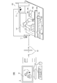
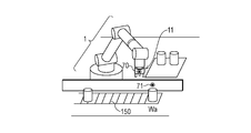
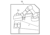
- FIG. 1 is a diagram illustrating a schematic configuration of a robot system 1000 according to the present embodiment.
- the robot apparatus 1 arranges the works Wa to Wd flowing from the belt conveyor 150 in the direction of arrow P on the tray 152 as an example.
- the robot system 1000 includes a robot apparatus 1 and an imaging apparatus 2 for imaging the situation of the robot apparatus 1, a robot system control apparatus 13 for controlling the robot apparatus 1 and the imaging apparatus 2, and an image of the imaging apparatus 2 by a worker from a remote place. And a computer 3 for browsing.
- the computer 3 and the robot system control device 13 are connected via a communication device 60, and are configured to be capable of remote communication.
- the remote place refers to a place where the operator cannot directly view the robot apparatus 1 to be operated, but can view the robot apparatus 1 by using the imaging device 2.
- the imaging device 2 is provided on a pillar 155, the imaging device 2 captures an image of the operation of the robot device 1, and displays an image of the robot device 1 on a display 31 of a computer 3 provided at a remote location.
- protective walls 153 and 154 are provided around the robot device 1. The protection walls 153 and 154 are provided for safety so that a work or a worker at the site does not hit the robot device 1.
- FIG. 2 is a diagram showing a configuration of the robot device 1 in the present embodiment.
- a six-axis articulated robot will be described as an example of the robot device.
- the robot apparatus 1 includes a base 10, a robot arm body 50 having six joints J1 to J6, and an end effector 11 for gripping a work.
- the robot device 1 is connected to a robot system control device 13 via a cable 12.
- the robot system control device 13 includes a network card for connecting to an external network, and is connected via a cable 14 to a communication device 60 for connecting to the external network.
- a robot hand having three fingers will be described as an example of the end effector 11.
- a robot hand having a finger portion is taken as an example.
- a mechanism that can perform work on the work such as an end effector that provides a suction mechanism instead of the finger portion and holds the work, is separately used. May be.
- the robot system control device 13 is configured by a CPU or the like including a microprocessor or the like.
- An external input device may be connected to the robot system control device 13.
- a teaching pendant or the like for a teacher to directly teach the robot device 1 near the robot device 1 is an example of the external input device.
- a command value is input to the robot controller 13 by an instructor using an external input device, and the control value from the controller 13 is passed to the robot arm main body 50 and the end effector 11, thereby arranging the works on the tray 152. Is performed by the robot device 1. Then, the work is operated by the robot apparatus 1 to manufacture articles and the like.
- the robot system control device 13 has a ROM for storing programs for controlling the corresponding drive units in accordance with various operations of the robot arm main body 50, data necessary for the control thereof, and the like. Further, a RAM is provided for developing data, setting values, programs, and the like necessary for controlling the robot arm body 50 and used as a work area of the CPU.
- the robot arm main body 50 has a configuration in which it is interconnected via a plurality of links (for example, serial links) via a plurality of joints (six axes).
- the links 51, 52, 53, 54, 55, and 56 of the robot arm main body 50 are driven via joints J1, J2, J3, J4, J5, and J6.
- Each joint has a motor (not shown) as a drive source.
- the base 10 of the robot arm main body 50 and the link 51 are connected by a joint J1 that rotates around a rotation axis in the Z-axis direction.
- the joint J1 has a movable range of about ⁇ 180 degrees from the initial posture, for example.
- the link 51 and the link 52 of the robot arm body 50 are connected by the joint J2.
- the rotation axis of the joint J2 coincides with the X-axis direction in the illustrated state.
- the joint J2 has a movable range of about ⁇ 80 degrees from the initial posture, for example.
- the link 52 and the link 53 of the robot arm body 50 are connected by the joint J3.
- the rotation axis of the joint J3 coincides with the X-axis direction in the illustrated state.
- the joint J3 has a movable range of about ⁇ 70 degrees from the initial posture, for example.
- the link 53 and the link 54 of the robot arm main body 50 are connected by a joint J4.
- the rotation axis of the joint J4 coincides with the Y-axis direction in the illustrated state.
- the joint J4 has a movable range of about ⁇ 180 degrees from the initial posture, for example.
- the link 54 and the link 55 of the robot arm main body 50 are connected by the joint J5.
- the rotation axis of the joint J5 coincides with the X-axis direction.
- the joint J5 has a movable range of about ⁇ 120 degrees from the initial posture.
- the link 55 and the link 56 of the robot arm main body 50 are connected by a joint J6.
- the rotation axis of the joint J6 coincides with the Z-axis direction.
- the joint J6 has a movable range of about ⁇ 240 degrees from the initial posture.
- the end effector 11 connected to the tip of the robot arm main body 50 employs a robot hand for performing an assembling operation and a moving operation on a production line.
- the end effector 11 can be attached to the link 56 by semi-fixed means such as screws, or can be attached by attaching / detaching means such as latching.
- FIG. 3 is a diagram showing a configuration of the imaging device 2.
- an imaging device capable of panning, tilting, and zooming will be described as an example.
- the imaging device 2 includes a camera base 20 and a movable unit 21, and an imaging unit 22 in the movable unit 21.
- the movable section 21 has a tilt motor, and the imaging section 22 is provided via a transmission mechanism such as a shaft or a bearing, so that the imaging section 22 can be rotated in the tilt direction indicated by the arrow A.
- the movable unit 21 has a pan motor, and the imaging unit 22 is provided via a transmission mechanism such as a shaft or a bearing, so that the imaging unit 22 can be rotated in the panning direction of arrow B.
- the imaging device 2 further includes a network card for connecting to an external network, and is connected via a cable 23 to a communication device 60 for connecting to the external network.
- the imaging device 2 can image the robot device 1 and a predetermined position around the robot device 1 by the movable unit 21, and display the captured image on the display 31 of the computer 3 at a remote location via the communication device 60. Can be.
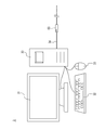
- FIG. 4 is a diagram showing a computer 3 for a worker to operate the robot apparatus 1 based on a captured image from the imaging device 2 in a remote place.
- the computer 3 includes an OS (Operation @ System) 30, a display 31, a keyboard 32, and a mouse 33.
- the display 31 displays an interface for controlling the robot device 1 at a remote location, an image captured by the image capturing device 2, and the like.
- the OS 30 further includes a network card for connecting to an external network, and is connected via a cable 34 to a communication device 60 for connecting to the external network.
- the operator can input a command value using the keyboard 32 and the mouse 33 based on the information displayed on the display 31, and can operate the robot apparatus 1 and the imaging apparatus 2 from a remote place.
- the robot apparatus 1 arranges the workpieces Wa to Wd flowing from the belt conveyor 150 in the direction of arrow P on the tray 152.
- the operation of the robot apparatus 1 for arranging the workpieces is prepared in advance. This is performed by the operation program. In the present embodiment, this operation is called a steady operation.
- an abnormality may occur and the operation of the robot apparatus 1 may stop.
- the position where the robot device 1 is stopped is called an abnormal stop position.
- the robot apparatus 1 in order for the robot apparatus 1 to resume the normal operation, the robot apparatus 1 must be moved to a position that is the first starting point in the normal operation. This position is called a return position, and the operation of the robot device 1 from the abnormal stop position to the return position is called a return.
- the worker confirms the state of the robot device 1 using the imaging device 2 from a remote location, and further creates a return trajectory of the robot device 1 and executes and operates the return trajectory.
- the monitoring of the robot device 1 is performed.
- the robot apparatus 1 when the robot apparatus 1 is operated by imaging with the imaging apparatus 2 so that the robot apparatus 1 does not come into contact with peripheral devices, the above operation can be easily performed without using a tracking marker while performing safety confirmation. It can be so. Details will be described below.
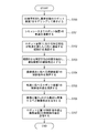
- FIG. 5 is a flowchart of a control method for the robot device 1 and the imaging device 2 in the present embodiment.
- the control method includes eight steps from S100 to S107. The specific method of each step will be described later with reference to the drawings.
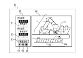
- FIG. 6A is a diagram showing an abnormal stop position and a return position of the robot device 1 when the operating robot device 1 abnormally stops.
- FIG. 6B is a diagram showing a screen configuration when the operator displays the robot apparatus 1 in an abnormal state on the display 31 of the computer 3 on a simulation.
- the robot apparatus 1 shows a state in which the end effector 11 is stopped at the abnormal stop position 70, and it is necessary to return the end effector 11 to the return position 71 above the workpiece Wa. is there.
- the present embodiment has a function of automatically generating the trajectory of the robot apparatus 1 from information on the start point and the end point.
- a 3D model display unit 80 for displaying a 3D screen and a trajectory generation display unit 90 for creating a trajectory of the robot apparatus 1 are displayed on the screen of the computer 3.
- the robot device 1 the work, and the like actually arranged are displayed as a 3D model simulation.
- the movable objects such as the robot device 1 and the belt conveyor 150 can be moved by the operator using the keyboard 32 and the mouse 33 as appropriate. Items displayed in the 3D model display unit 80 are marked with “′” for convenience of explanation.
- the trajectory generation display unit 90 includes a start point selection box 91 for setting a start point and an end point selection box 92 for setting an end point.
- start point selection box 91 and the end point selection box 92 the teaching points created by the operator are displayed, and the operator can select them.
- the trajectory generation display section 90 includes a trajectory generation button 93, a trajectory reproduction button 94, a pause button 95, and a stop button 96.
- the calculation of the trajectory is performed using a technique such as RRT (Rapidly-Exploring Random Trees).
- RRT Rapidly-Exploring Random Trees
- the trajectory referred to here represents a displacement value of each joint J1 to J6 of the robot device 1 for each control cycle.
- the displacement values of the joints J1 to J6 of a total of 500 sets are expressed.
- the robot system control device 13 and the OS 30 communicate with each other when an abnormality has occurred in the robot device 1 actually placed, and the robot device 1 'in the 3D model display unit 80 has the same posture as the robot device 1. Is displayed as follows.
- the OS 30 receives, from the robot system control device 13, the detection values of the encoders provided at the joints J1 to J6 of the robot device 1 in the abnormal state, and transmits the robot device 1 'modeled based on the detection values of the encoder. indicate. Thereby, the robot apparatus 1 'in the 3D model display unit 80 can be displayed so as to have the same posture as the robot apparatus 1 at the stage where the abnormality has occurred.
- a trajectory of the robot apparatus 1 for moving the end effector 11 from the abnormal stop position to the return position is created on a simulation based on a predetermined command received from a worker at a remote place.
- the operator inputs the position of the abnormal stop position 70 as the start point and the position of the return position 71 as the end point.
- the path indicates a transition of a position at which a specific part related to the robot device 1 is arranged in each control cycle of the trajectory when the robot device 1 is operated along the trajectory.
- the end effector 11 is set as a specific part.
- the control period of the robot device 1 is 4 ms and the operation of the robot device 1 takes 2000 ms
- the end effector 11 sets a total of 500 positions from 2000 ms / 4 ms. It will transition in order.
- the end effector 11 is taken as an example of the specific part related to the robot apparatus 1, but a predetermined place such as J1 to J6 which are joints of the robot arm main body 50 can be designated.
- the location selected as the specific part is a position where the imaging device 2 captures an image, for example, in the robot apparatus 1, if there is a part that is likely to come into contact with the protection walls 153 and 154, the usage is such that the part is selected as the specific part Can be done.
- the path can calculate the position of the end effector 11 by solving the forward kinematics of the robot based on the trajectory, that is, the displacement of each of the joints J1 to J6 of the robot, and can calculate the path of the end effector 11. I can do it.
- S102 is a path calculation step.
- a path 81 is displayed in the 3D model display unit 80 (FIG. 6B). Note that the worker may correct the trajectory of the robot device 1 generated in S101 while checking the route 81 and the captured image captured by the imaging device 2.
- an imaging viewpoint for controlling the movable portion 21 of the imaging device 2 is calculated.
- the worker in the remote place operates the robot apparatus 1 based on the image captured by the imaging apparatus 2, so that the operation of the robot apparatus 1 does not conform to the intention of the operator. It can cause trouble.
- an imaging viewpoint is extracted from the route 81 with a cycle of a response time of communication from a remote place to the imaging device 2.
- the response time refers to a time from when a teacher at a remote place inputs a command value to the imaging device 2 by the OS 30 until the imaging device 2 is driven based on the command value.
- the control cycle of the robot device 1 is 4 ms, and that the operation of the path 81 of the end effector 11 takes 280 ms. At this time, from 280 ms / 4 ms, the end effector 11 on the route 81 moves sequentially at 70 positions.
- the response time between the imaging device 2 and the OS 30 located at a remote place is often longer than the control cycle 4 ms of the robot device 1. For example, it is assumed that the response time between the imaging device 2 and the OS 30 takes 40 ms.
- the operation time on the path 81 of the end effector 11 is divided by the response time required for communication between the imaging device 2 and the OS 30, and the imaging viewpoint is calculated.
- S103 is an imaging viewpoint calculation step.
- FIG. 7 is a diagram showing a plurality of imaging viewpoints for imaging the route 81 by the imaging device 2 calculated in S103.
- the end effector 11 operates, six imaging viewpoints 87 from the imaging viewpoints 82 and a total of seven imaging viewpoints including the return position 71 are shown. If the abnormal stop position 70 is also added, the number of imaging viewpoints becomes eight in total.
- a control command value of the imaging device 2 corresponding to the imaging viewpoint is calculated. It is assumed that the control command of the imaging device 2 is composed of a combination of the rotation amount of the pan motor and the rotation amount of the tilt motor. These are calculated by the OS 30 using a simulator in which the robot device 1 and peripheral devices are modeled. The pan / tilt rotation amount can be calculated from the relative positional relationship between the imaging viewpoint and the imaging device. Further, the zoom amount of the imaging device 2 may be adjusted based on the distance between the imaging viewpoint and the imaging device 2.
- the imaging device 2 can be moved so as to capture the imaging viewpoint calculated in S103. It is assumed that the control command values of the imaging device 2 cannot be transmitted at once, and that the control command values must be continuously transmitted to keep the imaging device 2 moving.
- the robot device 1 can be operated from a remote place.
- the control command values of the robot device 1 all the control command values for operating the robot device 1 from the start position to the end position can be collectively transmitted in advance.
- the first imaging viewpoint to be imaged by the imaging unit 22 of the imaging device 2 is set.
- the position where the robot apparatus 1 is abnormally stopped that is, the abnormal stop position 70 is set as the first imaging viewpoint.
- control command value of the imaging device 2 calculated in S104 and the control command value of the robot device 1 calculated in S105 are transmitted to the robot system control device 13. Since the control command values of the robot device 1 can be transmitted collectively, the control command values of the imaging device 2 cannot be transmitted collectively, so it is necessary to transmit the control command values at intervals determined in S103. Thereby, the control of the viewpoint of the imaging device 2 following the operation of the robot device 1 can be easily executed.
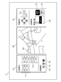
- FIG. 8 is a diagram showing a screen configuration of the computer 3 when the operator monitors the operation of the robot device 1.
- the display of the 3D model displayed on the display 31 is switched to the display of the captured image captured by the imaging device 2. It is assumed that the switching of the display is set so that the operator can switch the display at an arbitrary timing.
- the imaging display unit 100 is a cover for displaying a captured image captured by the imaging device 2
- the robot device operation unit 110 is an operation unit for operating the robot device 1
- the imaging operation unit 120 is an operation unit for operating the imaging device 2. It is an operation unit for performing.
- the robot device operation unit 110 includes two operation units used when the robot device 1 is manually operated and when the robot device 1 is automatically operated.
- an end effector operation button 111 for moving the end effector 11 of the robot apparatus 1 in the XYZ directions in an arbitrary coordinate system, and a joint operation for operating a rotation amount for each of the joints J1 to J6.
- a button 112 is provided.
- an execution button 113 for executing the trajectory calculated in step S101 by the actual robot apparatus 1 are provided.
- the imaging operation unit 120 also includes two operation units used when operating the imaging device 2 manually and when operating it automatically.
- the manual operation includes a viewpoint operation button 121 for performing a pan / tilt operation of the imaging device 2 and a zoom operation button 122 for performing a zoom-in / zoom-out operation.
- the display unit for performing the automatic operation includes an imaging target box 123 for specifying an imaging target of the imaging device 2.
- the part related to the robot apparatus 1 is displayed, and the route of S102 is calculated from the part selected here.
- the user wants the image capturing apparatus 2 to automatically perform image capturing based on the image capturing viewpoint calculated in step S103, the user clicks the follow-on button 124. If the tracking of the imaging device 2 is unnecessary, the tracking OFF button 125 is clicked.
- the above is the control method of the viewpoint operation of the imaging device 1 following the operation of the robot device 1 according to the present embodiment.
- the follow button 124 and pressing the execute button 113 for executing the automatic operation of the robot apparatus 1 it is easy to control the camera that follows the operation of the robot apparatus 1 without prior preparation such as setting a tracking marker. You can do it.
- the operation time of the path 81 of the end effector 11 is divided by the response time required for communication between the imaging device 2 and the OS 30 to calculate the imaging viewpoint. Thereby, the operation time of the end effector 11 and the imaging time of the imaging device 2 can be made to coincide with each other, so that the operation can be prevented from being out of synchronization.
- the imaging viewpoint 82 next to the abnormal stop position 70 may be set as the first imaging viewpoint in S106. In this way, the operation of the robot device 1 can be monitored in advance, and the operation of the robot device 1 can more reliably prevent a predetermined position in the robot device 1 from contacting peripheral devices. it can.
- the proactive operation may be realized by operating the imaging device 2 first based on the imaging viewpoint, and then starting the operation of the robot device 1 on the route 81 at a predetermined timing. At this time, it can be realized by operating the imaging device 2 such that the end effector 11 temporarily moves out of the imaging range of the imaging device 2 but is again positioned in the imaging range based on the imaging viewpoint.
- the imaging display unit 100 may simultaneously display the path 81 calculated in S102 and the imaging viewpoint calculated in S103 on a captured image captured by the imaging device 2. This makes it possible to assume how the robot device 1 will operate next, so that it is possible to further prevent a predetermined position in the robot device 1 from contacting peripheral devices.
- the 3D model display unit 80 and the imaging display unit 100 are displayed separately, but may be displayed simultaneously. Thereby, it is possible to confirm the difference between the operation of the simulation and the operation of the actual machine.
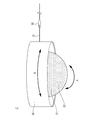
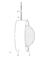
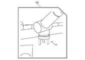
- FIG. 10 is a diagram illustrating a configuration of the imaging device 4 according to the present embodiment.
- the imaging device 4 is an omnidirectional camera, and includes a camera base 40, an imaging unit 41, and a cable 42 for network connection.
- the imaging unit 41 is configured to be able to take an image in a 360-degree direction with reference to a place where the imaging device 4 is installed.
- the imaging device 4 includes a network card for connecting to an external network, and is connected via a cable 42 to a communication device 60 for connecting to an external network.
- the imaging device 4 of the present embodiment has neither a mechanism for moving the viewpoint of the imaging unit nor a mechanism for zooming as in the first embodiment, but has a digital zoom for locally enlarging a part of a captured image. It is possible. Therefore, the control of the imaging device 4 in the present embodiment can control the viewpoint following the target object to be watched by controlling so as to perform digital zoom to a position corresponding to the imaging viewpoint.
- FIG. 11 is a diagram showing the imaging display unit 100 that displays an image captured by the imaging device 4 according to the present embodiment.
- FIG. 11A illustrates a captured image that is normally captured by the imaging device 4.
- FIG. 11B shows a captured image when digital zoom is performed on a position corresponding to the imaging viewpoint calculated in S103 of the first embodiment.
- a pan / tilt / zoom camera requires a driving source such as a pan motor or a tilt motor, which may increase costs. .
- the imaging viewpoint may be displayed by adjusting the magnification of the image projected by the imaging device 4 using a lens.
- FIG. 12 a process for adding a marker on a captured image may be performed at a position corresponding to the calculated imaging viewpoint.
- FIG. 11 shows a marker 141 at a position corresponding to an imaging viewpoint in an image captured by the imaging apparatus.
- a button for automatically digitally zooming the marker 141 when the operator presses the button, the user can gaze at a specific part while viewing the entire robot apparatus 1, so that the operation of the robot apparatus 1 can be easily performed. Can be monitored remotely.
- the control program for implementing the present invention may be recorded on any recording medium as long as it is a computer-readable recording medium.
- the recording medium for supplying the control program an HDD, an external storage device, a recording disk, or the like may be used.
- a control unit may be provided in the imaging device, and the control program and the trajectory data of the robot device may be stored in the control unit, and the first embodiment and the second embodiment may be implemented by the imaging device alone.
- the robot arm body 50 is a six-axis articulated robot having six joints has been described, but the number of joints is not limited to this.
- the vertical multi-axis configuration is shown as the type of the robot arm main body 50, the same configuration as described above can be implemented in a joint of the robot arm main body 50 of a different type such as a parallel link type.
- each motor of the robot arm body 50 is not limited to the above-described configuration, and a drive source for driving each joint may be a device such as an artificial muscle, for example.
- the imaging device 2 and the imaging device 4 of the first and second embodiments are single, a plurality of imaging devices are used, the imaging devices are controlled in conjunction with each other, and the imaging viewpoint is imaged. No problem.
- the screen configuration for monitoring the operation of the robot apparatus being imaged by the imaging apparatus using FIGS. 8, 9, 11, and 12 is a computer. 3 is displayed on the display 31, but is not limited to this.
- the information may be displayed on various interfaces such as an external input device such as a teaching pendant or a portable terminal capable of operating the robot device by an application or the like.
Abstract
L'invention concerne un système de robot comprenant un dispositif robot et un dispositif d'imagerie, caractérisé en ce que le système de robot comporte un dispositif de commande destiné à la commande du dispositif robot et du dispositif d'imagerie ; et en ce que le dispositif de commande commande le fonctionnement du dispositif d'imagerie de sorte qu'un site prescrit soit imagé même si le dispositif robot est actionné sur la base d'un trajet sur lequel un site prescrit du dispositif robot est actionné.
Priority Applications (3)
| Application Number | Priority Date | Filing Date | Title |
|---|---|---|---|
| EP19860262.5A EP3851255A4 (fr) | 2018-09-12 | 2019-08-08 | Système de robot, dispositif de commande de système de robot, procédé de commande de système de robot, dispositif d'imagerie, programme de commande et support d'enregistrement |
| CN201980059795.4A CN113165186A (zh) | 2018-09-12 | 2019-08-08 | 机器人系统及其控制装置和控制方法、摄像装置、控制程序和存储介质 |
| US17/192,737 US20210187751A1 (en) | 2018-09-12 | 2021-03-04 | Robot system, control apparatus of robot system, control method of robot system, imaging apparatus, and storage medium |
Applications Claiming Priority (2)
| Application Number | Priority Date | Filing Date | Title |
|---|---|---|---|
| JP2018-170833 | 2018-09-12 | ||
| JP2018170833A JP7163115B2 (ja) | 2018-09-12 | 2018-09-12 | ロボットシステム、ロボットシステムの制御方法、物品の製造方法、制御装置、操作装置、撮像装置、制御プログラム及び記録媒体 |
Related Child Applications (1)
| Application Number | Title | Priority Date | Filing Date |
|---|---|---|---|
| US17/192,737 Continuation US20210187751A1 (en) | 2018-09-12 | 2021-03-04 | Robot system, control apparatus of robot system, control method of robot system, imaging apparatus, and storage medium |
Publications (1)
| Publication Number | Publication Date |
|---|---|
| WO2020054281A1 true WO2020054281A1 (fr) | 2020-03-19 |
Family
ID=69777263
Family Applications (1)
| Application Number | Title | Priority Date | Filing Date |
|---|---|---|---|
| PCT/JP2019/031302 WO2020054281A1 (fr) | 2018-09-12 | 2019-08-08 | Système de robot, dispositif de commande de système de robot, procédé de commande de système de robot, dispositif d'imagerie, programme de commande et support d'enregistrement |
Country Status (5)
| Country | Link |
|---|---|
| US (1) | US20210187751A1 (fr) |
| EP (1) | EP3851255A4 (fr) |
| JP (2) | JP7163115B2 (fr) |
| CN (1) | CN113165186A (fr) |
| WO (1) | WO2020054281A1 (fr) |
Families Citing this family (4)
| Publication number | Priority date | Publication date | Assignee | Title |
|---|---|---|---|---|
| JP7163115B2 (ja) | 2018-09-12 | 2022-10-31 | キヤノン株式会社 | ロボットシステム、ロボットシステムの制御方法、物品の製造方法、制御装置、操作装置、撮像装置、制御プログラム及び記録媒体 |
| WO2022124398A1 (fr) * | 2020-12-10 | 2022-06-16 | 三菱電機株式会社 | Système de manipulateur à télécommande et système d'aide à la télécommande |
| US20220379475A1 (en) * | 2021-05-25 | 2022-12-01 | Fanuc Corporation | Transparent object bin picking |
| WO2024089813A1 (fr) * | 2022-10-26 | 2024-05-02 | 株式会社Fuji | Robot |
Citations (8)
| Publication number | Priority date | Publication date | Assignee | Title |
|---|---|---|---|---|
| JPH06270076A (ja) * | 1993-03-25 | 1994-09-27 | Nippon Steel Corp | 遠隔操作用カメラ制御装置 |
| JPH07244519A (ja) * | 1994-03-04 | 1995-09-19 | Nippon Telegr & Teleph Corp <Ntt> | 画像による可動物体の運動制御方法 |
| JPH10249786A (ja) * | 1997-03-14 | 1998-09-22 | Yaskawa Electric Corp | マニピュレータの制御装置および操作支援装置 |
| JP2003150569A (ja) * | 2001-11-09 | 2003-05-23 | Sony Corp | 情報処理システムおよび情報処理方法、プログラムおよび記録媒体、並びに情報処理装置 |
| JP2012106317A (ja) * | 2010-11-18 | 2012-06-07 | Kobe Steel Ltd | 溶接状況監視方法及び溶接状況監視装置 |
| JP2014079824A (ja) * | 2012-10-15 | 2014-05-08 | Toshiba Corp | 作業画面表示方法および作業画面表示装置 |
| JP2016111649A (ja) | 2014-12-10 | 2016-06-20 | 沖電気工業株式会社 | 監視システム、映像解析装置、映像解析方法およびプログラム |
| WO2017037908A1 (fr) * | 2015-09-03 | 2017-03-09 | 富士機械製造株式会社 | Système robotique |
Family Cites Families (33)
| Publication number | Priority date | Publication date | Assignee | Title |
|---|---|---|---|---|
| US5319443A (en) * | 1991-03-07 | 1994-06-07 | Fanuc Ltd | Detected position correcting method |
| US5521843A (en) * | 1992-01-30 | 1996-05-28 | Fujitsu Limited | System for and method of recognizing and tracking target mark |
| JP3394322B2 (ja) * | 1994-05-19 | 2003-04-07 | ファナック株式会社 | 視覚センサを用いた座標系設定方法 |
| US5553609A (en) * | 1995-02-09 | 1996-09-10 | Visiting Nurse Service, Inc. | Intelligent remote visual monitoring system for home health care service |
| AU718608B2 (en) * | 1996-03-15 | 2000-04-20 | Gizmoz Israel (2002) Ltd. | Programmable computer graphic objects |
| EP1279081B1 (fr) * | 2000-05-01 | 2012-01-04 | iRobot Corporation | Procede et systeme permettant de commander un robot mobile a distance |
| JP2002164066A (ja) * | 2000-11-22 | 2002-06-07 | Mitsubishi Heavy Ind Ltd | 積層型熱交換器 |
| US7432949B2 (en) * | 2003-08-20 | 2008-10-07 | Christophe Remy | Mobile videoimaging, videocommunication, video production (VCVP) system |
| US20070075048A1 (en) * | 2005-09-30 | 2007-04-05 | Nachi-Fujikoshi Corp. | Welding teaching point correction system and calibration method |
| JP4153528B2 (ja) * | 2006-03-10 | 2008-09-24 | ファナック株式会社 | ロボットシミュレーションのための装置、プログラム、記録媒体及び方法 |
| US7313464B1 (en) * | 2006-09-05 | 2007-12-25 | Adept Technology Inc. | Bin-picking system for randomly positioned objects |
| JP5799516B2 (ja) * | 2011-02-03 | 2015-10-28 | セイコーエプソン株式会社 | ロボット装置、検査装置、検査プログラム、および検査方法 |
| WO2013005862A1 (fr) * | 2011-07-07 | 2013-01-10 | Olympus Corporation | Manipulateur maître-esclave médical |
| JP5892360B2 (ja) * | 2011-08-02 | 2016-03-23 | ソニー株式会社 | ロボット指示装置、ロボット指示方法、プログラム、及び通信システム |
| WO2013023130A1 (fr) * | 2011-08-11 | 2013-02-14 | Siemens Healthcare Diagnostics Inc. | Procédés et appareil pour étalonner une orientation entre un préhenseur de robot et une caméra |
| JP5561260B2 (ja) * | 2011-09-15 | 2014-07-30 | 株式会社安川電機 | ロボットシステム及び撮像方法 |
| EP3932628A1 (fr) * | 2012-12-10 | 2022-01-05 | Intuitive Surgical Operations, Inc. | Évitement de collision au cours d'un mouvement commandé de dispositif de capture d'images et de bras mobiles de dispositif manipulable |
| JP6153366B2 (ja) * | 2013-03-29 | 2017-06-28 | 株式会社バンダイナムコエンターテインメント | 画像生成システム及びプログラム |
| JP6322959B2 (ja) | 2013-11-05 | 2018-05-16 | セイコーエプソン株式会社 | ロボット、ロボットシステム、及びロボット制御装置 |
| US9283674B2 (en) * | 2014-01-07 | 2016-03-15 | Irobot Corporation | Remotely operating a mobile robot |
| US9259844B2 (en) * | 2014-02-12 | 2016-02-16 | General Electric Company | Vision-guided electromagnetic robotic system |
| CN106029308B (zh) * | 2014-02-28 | 2019-10-29 | 索尼公司 | 机械臂设备、校准方法以及计算机可读存储介质 |
| JP2016070762A (ja) * | 2014-09-29 | 2016-05-09 | ファナック株式会社 | 対象物の三次元位置を検出する検出方法および検出装置 |
| WO2017115425A1 (fr) * | 2015-12-28 | 2017-07-06 | オリンパス株式会社 | Système de manipulateur médical |
| JP2017124468A (ja) * | 2016-01-14 | 2017-07-20 | キヤノン株式会社 | ロボット制御方法、部品の製造方法、ロボット装置、プログラム及び記録媒体 |
| EP4160150A1 (fr) * | 2016-08-26 | 2023-04-05 | Panasonic Intellectual Property Corporation of America | Procédé et appareil de traitement d'informations tridimensionnelles |
| JP2018075121A (ja) * | 2016-11-08 | 2018-05-17 | ソニー株式会社 | 医療用支持アーム装置 |
| EP3591984A4 (fr) * | 2017-02-28 | 2020-07-22 | Sony Corporation | Dispositif de traitement d'informations, procédé de traitement d'informations et programme |
| JP6392922B1 (ja) * | 2017-03-21 | 2018-09-19 | ファナック株式会社 | 検査システムの検査対象外となる領域を算出する装置、および検査対象外となる領域を算出する方法 |
| US10690466B2 (en) * | 2017-04-19 | 2020-06-23 | Global Tel*Link Corporation | Mobile correctional facility robots |
| WO2018213131A1 (fr) * | 2017-05-18 | 2018-11-22 | Pcms Holdings, Inc. | Système et procédé de distribution et de rendu de contenu sous la forme d'une combinaison de vidéo sphérique et d'actif 3d |
| US10816939B1 (en) * | 2018-05-07 | 2020-10-27 | Zane Coleman | Method of illuminating an environment using an angularly varying light emitting device and an imager |
| JP7163115B2 (ja) | 2018-09-12 | 2022-10-31 | キヤノン株式会社 | ロボットシステム、ロボットシステムの制御方法、物品の製造方法、制御装置、操作装置、撮像装置、制御プログラム及び記録媒体 |
-
2018
- 2018-09-12 JP JP2018170833A patent/JP7163115B2/ja active Active
-
2019
- 2019-08-08 EP EP19860262.5A patent/EP3851255A4/fr active Pending
- 2019-08-08 CN CN201980059795.4A patent/CN113165186A/zh active Pending
- 2019-08-08 WO PCT/JP2019/031302 patent/WO2020054281A1/fr unknown
-
2021
- 2021-03-04 US US17/192,737 patent/US20210187751A1/en active Pending
-
2022
- 2022-10-19 JP JP2022167636A patent/JP7423726B2/ja active Active
Patent Citations (8)
| Publication number | Priority date | Publication date | Assignee | Title |
|---|---|---|---|---|
| JPH06270076A (ja) * | 1993-03-25 | 1994-09-27 | Nippon Steel Corp | 遠隔操作用カメラ制御装置 |
| JPH07244519A (ja) * | 1994-03-04 | 1995-09-19 | Nippon Telegr & Teleph Corp <Ntt> | 画像による可動物体の運動制御方法 |
| JPH10249786A (ja) * | 1997-03-14 | 1998-09-22 | Yaskawa Electric Corp | マニピュレータの制御装置および操作支援装置 |
| JP2003150569A (ja) * | 2001-11-09 | 2003-05-23 | Sony Corp | 情報処理システムおよび情報処理方法、プログラムおよび記録媒体、並びに情報処理装置 |
| JP2012106317A (ja) * | 2010-11-18 | 2012-06-07 | Kobe Steel Ltd | 溶接状況監視方法及び溶接状況監視装置 |
| JP2014079824A (ja) * | 2012-10-15 | 2014-05-08 | Toshiba Corp | 作業画面表示方法および作業画面表示装置 |
| JP2016111649A (ja) | 2014-12-10 | 2016-06-20 | 沖電気工業株式会社 | 監視システム、映像解析装置、映像解析方法およびプログラム |
| WO2017037908A1 (fr) * | 2015-09-03 | 2017-03-09 | 富士機械製造株式会社 | Système robotique |
Also Published As
| Publication number | Publication date |
|---|---|
| CN113165186A (zh) | 2021-07-23 |
| EP3851255A1 (fr) | 2021-07-21 |
| JP7423726B2 (ja) | 2024-01-29 |
| EP3851255A4 (fr) | 2022-06-15 |
| US20210187751A1 (en) | 2021-06-24 |
| JP2022183308A (ja) | 2022-12-08 |
| JP2020040184A (ja) | 2020-03-19 |
| JP7163115B2 (ja) | 2022-10-31 |
Similar Documents
| Publication | Publication Date | Title |
|---|---|---|
| JP6814735B2 (ja) | 遠隔操縦マニピュレータシステム及びその運転方法 | |
| WO2020054281A1 (fr) | Système de robot, dispositif de commande de système de robot, procédé de commande de système de robot, dispositif d'imagerie, programme de commande et support d'enregistrement | |
| WO2020090809A1 (fr) | Dispositif d'entrée externe, système de robot, procédé de commande pour système de robot, programme de commande et support d'enregistrement | |
| US10737396B2 (en) | Method and apparatus for robot path teaching | |
| US7211978B2 (en) | Multiple robot arm tracking and mirror jog | |
| JP7041492B2 (ja) | ロボットシステム | |
| JP2004265041A (ja) | ロボット教示装置 | |
| WO2020027106A1 (fr) | Système de robot | |
| Sugandi et al. | Hand tracking-based motion control for robot arm using stereo camera | |
| WO2023167324A1 (fr) | Système de production et procédé de reproduction |
Legal Events
| Date | Code | Title | Description |
|---|---|---|---|
| 121 | Ep: the epo has been informed by wipo that ep was designated in this application |
Ref document number: 19860262 Country of ref document: EP Kind code of ref document: A1 |
|
| NENP | Non-entry into the national phase |
Ref country code: DE |
|
| ENP | Entry into the national phase |
Ref document number: 2019860262 Country of ref document: EP Effective date: 20210412 |