WO2020054022A1 - 通信システム、受信端末、通信方法、およびプログラム - Google Patents
通信システム、受信端末、通信方法、およびプログラム Download PDFInfo
- Publication number
- WO2020054022A1 WO2020054022A1 PCT/JP2018/033996 JP2018033996W WO2020054022A1 WO 2020054022 A1 WO2020054022 A1 WO 2020054022A1 JP 2018033996 W JP2018033996 W JP 2018033996W WO 2020054022 A1 WO2020054022 A1 WO 2020054022A1
- Authority
- WO
- WIPO (PCT)
- Prior art keywords
- control circuit
- terminal
- transmission
- cycle
- polling request
- Prior art date
- Legal status (The legal status is an assumption and is not a legal conclusion. Google has not performed a legal analysis and makes no representation as to the accuracy of the status listed.)
- Ceased
Links
Images











Classifications
-
- H—ELECTRICITY
- H04—ELECTRIC COMMUNICATION TECHNIQUE
- H04N—PICTORIAL COMMUNICATION, e.g. TELEVISION
- H04N1/00—Scanning, transmission or reproduction of documents or the like, e.g. facsimile transmission; Details thereof
- H04N1/32—Circuits or arrangements for control or supervision between transmitter and receiver or between image input and image output device, e.g. between a still-image camera and its memory or between a still-image camera and a printer device
-
- G—PHYSICS
- G06—COMPUTING OR CALCULATING; COUNTING
- G06F—ELECTRIC DIGITAL DATA PROCESSING
- G06F13/00—Interconnection of, or transfer of information or other signals between, memories, input/output devices or central processing units
-
- G—PHYSICS
- G08—SIGNALLING
- G08B—SIGNALLING SYSTEMS, e.g. PERSONAL CALLING SYSTEMS; ORDER TELEGRAPHS; ALARM SYSTEMS
- G08B13/00—Burglar, theft or intruder alarms
- G08B13/18—Actuation by interference with heat, light, or radiation of shorter wavelength; Actuation by intruding sources of heat, light, or radiation of shorter wavelength
- G08B13/189—Actuation by interference with heat, light, or radiation of shorter wavelength; Actuation by intruding sources of heat, light, or radiation of shorter wavelength using passive radiation detection systems
- G08B13/19—Actuation by interference with heat, light, or radiation of shorter wavelength; Actuation by intruding sources of heat, light, or radiation of shorter wavelength using passive radiation detection systems using infrared-radiation detection systems
-
- H—ELECTRICITY
- H04—ELECTRIC COMMUNICATION TECHNIQUE
- H04N—PICTORIAL COMMUNICATION, e.g. TELEVISION
- H04N1/00—Scanning, transmission or reproduction of documents or the like, e.g. facsimile transmission; Details thereof
- H04N1/32—Circuits or arrangements for control or supervision between transmitter and receiver or between image input and image output device, e.g. between a still-image camera and its memory or between a still-image camera and a printer device
- H04N1/327—Initiating, continuing or ending a single-mode communication; Handshaking therefor
- H04N1/32793—Controlling a receiver or transmitter non-communication function in response to a communication control signal
-
- H—ELECTRICITY
- H04—ELECTRIC COMMUNICATION TECHNIQUE
- H04N—PICTORIAL COMMUNICATION, e.g. TELEVISION
- H04N1/00—Scanning, transmission or reproduction of documents or the like, e.g. facsimile transmission; Details thereof
- H04N1/32—Circuits or arrangements for control or supervision between transmitter and receiver or between image input and image output device, e.g. between a still-image camera and its memory or between a still-image camera and a printer device
- H04N1/333—Mode signalling or mode changing; Handshaking therefor
-
- H—ELECTRICITY
- H04—ELECTRIC COMMUNICATION TECHNIQUE
- H04N—PICTORIAL COMMUNICATION, e.g. TELEVISION
- H04N1/00—Scanning, transmission or reproduction of documents or the like, e.g. facsimile transmission; Details thereof
- H04N1/38—Circuits or arrangements for blanking or otherwise eliminating unwanted parts of pictures
-
- H—ELECTRICITY
- H04—ELECTRIC COMMUNICATION TECHNIQUE
- H04N—PICTORIAL COMMUNICATION, e.g. TELEVISION
- H04N1/00—Scanning, transmission or reproduction of documents or the like, e.g. facsimile transmission; Details thereof
- H04N1/387—Composing, repositioning or otherwise geometrically modifying originals
-
- H—ELECTRICITY
- H04—ELECTRIC COMMUNICATION TECHNIQUE
- H04N—PICTORIAL COMMUNICATION, e.g. TELEVISION
- H04N7/00—Television systems
- H04N7/18—Closed-circuit television [CCTV] systems, i.e. systems in which the video signal is not broadcast
-
- Y—GENERAL TAGGING OF NEW TECHNOLOGICAL DEVELOPMENTS; GENERAL TAGGING OF CROSS-SECTIONAL TECHNOLOGIES SPANNING OVER SEVERAL SECTIONS OF THE IPC; TECHNICAL SUBJECTS COVERED BY FORMER USPC CROSS-REFERENCE ART COLLECTIONS [XRACs] AND DIGESTS
- Y02—TECHNOLOGIES OR APPLICATIONS FOR MITIGATION OR ADAPTATION AGAINST CLIMATE CHANGE
- Y02D—CLIMATE CHANGE MITIGATION TECHNOLOGIES IN INFORMATION AND COMMUNICATION TECHNOLOGIES [ICT], I.E. INFORMATION AND COMMUNICATION TECHNOLOGIES AIMING AT THE REDUCTION OF THEIR OWN ENERGY USE
- Y02D30/00—Reducing energy consumption in communication networks
- Y02D30/70—Reducing energy consumption in communication networks in wireless communication networks
Definitions
- the present invention relates to a communication system, a receiving terminal, a communication method, and a program.
- a communication system utilizing polling has a receiving terminal and a transmitting terminal.
- the receiving terminal transmits a polling request to the transmitting terminal.
- the transmitting terminal receives the polling request and transmits response data to the receiving terminal.
- Patent Document 1 discloses a technique related to polling.
- the digital camera disclosed in Patent Document 1 is connected to a facsimile via a network.
- the digital camera corresponds to the transmitting terminal, and the facsimile corresponds to the receiving terminal.
- the polling mode is set on the digital camera, and the digital camera waits for an incoming call from the facsimile.
- the digital camera receives an incoming call from a facsimile and establishes a connection with the facsimile. After the connection is established, the digital camera automatically presses the shutter and sends the generated data to the facsimile. After the transmission is completed, the digital camera waits for the next incoming call from the facsimile.
- the transmitting terminal transmits response data to the receiving terminal based on the polling request received from the receiving terminal.
- the transmission timing of the response data depends on the processing load of the response data on the transmitting terminal. Therefore, the interval between the reception of the polling request and the transmission of the response data is not always constant.
- the receiving terminal when a receiving terminal continuously requests data according to polling, the receiving terminal often transmits the next polling request immediately after receiving a response in order to obtain more data. Since the response data may not be transmitted from the transmission terminal at a constant interval, the transmission interval of the polling request is not always constant. Even if the receiving terminal needs to periodically acquire data at regular intervals, it is difficult for the receiving terminal to acquire data at regular intervals. Also in the technique disclosed in Patent Document 1, if the interval between incoming calls from a facsimile is not constant, the interval at which the digital camera transmits data is not constant.
- An object of the present invention is to provide a communication system, a receiving terminal, a communication method, and a program capable of simplifying control for transmitting a polling request and periodically acquiring data. .
- a communication system has a receiving terminal and a first transmitting terminal.
- the receiving terminal has a first communication device and a first control circuit.
- the first communication device transmits a polling request to the first transmission terminal and receives response data from the first transmission terminal.
- the first transmitting terminal has a second communication device.
- the second communication device receives the polling request from the receiving terminal, and transmits the response data to the receiving terminal based on the polling request.
- the first control circuit causes the first communication device to transmit the polling request to the first transmission terminal in at least one of two or more consecutive periods.
- the first control circuit causes the first communication device to stop transmitting the polling request in a cycle following the transmission cycle, and Wait for reception.
- the transmission cycle is a cycle at which the polling request is transmitted.
- the first control circuit causes the first communication device to transmit the polling request to the first transmission terminal in a cycle following a cycle in which the reception of the response data is completed.
- the first transmitting terminal may further include an image sensor for imaging a subject and generating image data.
- the response data may be the image data.
- the first control circuit may cause an image based on the received image data to be displayed on a display at intervals based on a frame rate.
- the first control circuit may cause the first communication device to transmit the polling request to the first transmission terminal at a transmission timing.
- the transmission timing may be a timing at which the interval has elapsed from a timing at which the polling request was transmitted.
- the communication system may include two or more first transmitting terminals.
- the first control circuit may cause the first communication device to transmit the polling request to all of the two or more first transmission terminals in at least one of the two or more periods.
- the first control circuit sends the polling request to the first communication device at the transmission timing.
- the transmission may be performed to all of the two or more first transmission terminals. If the reception of at least one of the image data by the two or more first transmission terminals is not completed in the transmission cycle, the first control circuit may control the first communication device in a cycle subsequent to the transmission cycle.
- the transmission of the polling request may be stopped and the reception of the image data may be waited.
- the first control circuit in a cycle following the cycle in which the reception of the last image data among all the image data of the two or more first transmission terminals is completed, the first communication device
- the polling request may be transmitted to all of the two or more first transmitting terminals.
- the communication system may include two or more first transmitting terminals.
- the first control circuit may cause the display to simultaneously display two or more images based on the two or more image data received from all of the two or more first transmission terminals at the interval. .
- the communication system may further include a second transmitting terminal.
- a third communication device that receives the polling request from the receiving terminal, and transmits sensor data output from a sensor to the receiving terminal as the response data based on the polling request; May be provided.
- the first control circuit may cause the first communication device to transmit the polling request to the first transmission terminal and the second transmission terminal in at least one of the two or more cycles.
- the first control circuit includes the first control circuit. May transmit the polling request to the first transmission terminal and the second transmission terminal at the transmission timing.
- the first control circuit transmits the polling request to the first communication device in a cycle subsequent to the transmission cycle. It may be stopped and wait for reception of at least one of the image data and the sensor data.
- the first control circuit is configured to transmit the polling request to the first communication device at the transmission timing in a cycle following a cycle in which the reception of the image data and the sensor data is completed. 2 may be transmitted to the transmitting terminal.
- the first control circuit may simultaneously display the image and the received sensor data on the display at the interval.
- the first control circuit when the reception of the response data is not completed in the standby period, the first control circuit may be configured to perform the operation in the standby period. In a subsequent cycle, the first communication device may transmit the polling request to the first transmitting terminal.
- the waiting period may include at least two continuous cycles of the two or more cycles. If the reception of the response data is not completed in the two or more consecutive waiting periods, the first control circuit may cause the first communication device to end communication with the first transmitting terminal.
- the first communication device and the second communication device may wirelessly communicate the polling request and the response data.
- the first control circuit may determine a communication environment between the receiving terminal and the first transmitting terminal. If the first communication device terminates the communication with the first transmitting terminal and the first control circuit determines that the communication environment has deteriorated, the first control circuit determines that the first May change a communication channel used for communication with the first transmitting terminal and restart communication with the first transmitting terminal.
- the first transmitting terminal may further include a second control circuit.
- the second control circuit may determine whether or not the response data can be transmitted within a predetermined interval from a timing at which the polling request is received. When the second control circuit determines that the response data cannot be transmitted within the predetermined interval, the second control circuit causes the second communication device to transmit the response data to the receiving terminal. Instead, the instruction data may be transmitted to the receiving terminal, and the instruction data may indicate an end of communication between the receiving terminal and the first transmitting terminal.
- the first control circuit sets a communication environment between the receiving terminal and the first transmitting terminal. You may decide. When the first control circuit determines that the communication environment has deteriorated, the first control circuit sets the cycle at which the polling request is transmitted to be longer than the cycle before the communication environment deteriorates. You may.
- the first transmission terminal may further include a second control circuit and a data compression circuit.
- the second control circuit may determine a communication environment between the receiving terminal and the first transmitting terminal.
- the data compression circuit may compress the response data.
- the second communication device may transmit the compressed response data to the receiving terminal based on the polling request. If the second control circuit determines that the communication environment has deteriorated, the second control circuit may set the compression ratio of the response data higher than the compression ratio before the communication environment deteriorated. Good.
- the receiving terminal has a communication device and a control circuit.
- the communication device transmits a polling request to a transmitting terminal and receives response data from the transmitting terminal.
- the control circuit causes the communication device to transmit the polling request to a transmitting terminal in at least one of two or more consecutive periods. If the reception of the response data is not completed in the transmission cycle, the control circuit causes the communication device to stop transmitting the polling request and wait for the reception of the response data in a cycle subsequent to the transmission cycle.
- the transmission cycle is a cycle at which the polling request is transmitted.
- the control circuit causes the communication device to transmit the polling request to the transmitting terminal in a cycle following a cycle in which the reception of the response data is completed.
- a communication method has a first step, a second step, and a third step.
- the control circuit causes the communication device to transmit a polling request to the transmitting terminal in at least one of two or more consecutive periods. If the receiving of the response data of the transmitting terminal is not completed in a transmission cycle, in the second step, the control circuit causes the communication device to stop transmitting the polling request in a cycle following the transmission cycle, and Wait for reception of the response data.
- the transmission cycle is a cycle at which the polling request is transmitted.
- the control circuit causes the communication device to transmit the polling request to the transmission terminal in a cycle following a cycle in which the reception of the response data is completed.
- a program for causing a computer to execute a first step, a second step, and a third step In the first step, the computer causes the communication device to transmit a polling request to the transmitting terminal in at least one of two or more consecutive periods. In a case where the reception of the response data of the transmitting terminal is not completed in a transmission cycle, in the second step, in a cycle following the transmission cycle, the computer causes the communication device to stop transmitting the polling request, and Wait for the response data.
- the transmission cycle is a cycle at which the polling request is transmitted.
- the computer causes the communication device to transmit the polling request to the transmitting terminal in a cycle following a cycle in which the reception of the response data is completed.
- the communication system, the receiving terminal, the communication method, and the program can simplify control for transmitting a polling request and can periodically acquire data.
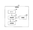
- FIG. 1 is a block diagram illustrating a configuration of a communication system according to a first exemplary embodiment of the present invention.
- FIG. 2 is a block diagram illustrating a configuration of a receiving terminal according to the first embodiment of the present invention.
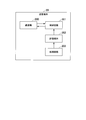
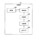
- FIG. 2 is a block diagram illustrating a configuration of a transmission terminal according to the first embodiment of the present invention.
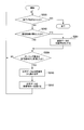
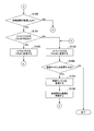
- 6 is a flowchart illustrating a procedure of a process executed by the receiving terminal according to the first embodiment of the present invention.
- 5 is a flowchart illustrating a procedure of a process executed by the transmitting terminal according to the first embodiment of the present invention.
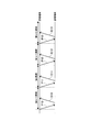
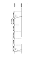
- 5 is a timing chart illustrating communication executed by the receiving terminal and the transmitting terminal according to the first embodiment of the present invention.
- FIG. 5 is a timing chart illustrating communication executed by the receiving terminal and the transmitting terminal according to the first embodiment of the present invention.
- 5 is a timing chart illustrating communication executed by the receiving terminal and the transmitting terminal according to the first embodiment of the present invention.
- It is a block diagram showing the composition of the receiving terminal of a 2nd embodiment of the present invention.
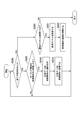
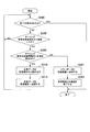
- FIG. 9 is a block diagram illustrating a configuration of a transmission terminal according to a second embodiment of the present invention. It is a flowchart which shows the procedure of the process which the receiving terminal of 2nd Embodiment of this invention performs. It is a figure showing a screen of a display of a 2nd embodiment of the present invention. It is a block diagram showing the composition of the communication system of a 3rd embodiment of the present invention.
- FIG. 14 is a block diagram illustrating a configuration of a transmission terminal according to a fourth embodiment of the present invention. It is a flowchart which shows the procedure of the process which the receiving terminal of 4th Embodiment of this invention performs. It is a flowchart which shows the procedure of the process which the receiving terminal of 4th Embodiment of this invention performs. It is a figure showing the screen of the display of a 4th embodiment of the present invention.
- FIG. 1 shows a configuration of a communication system 1 according to the first embodiment of the present invention.
- the communication system 1 illustrated in FIG. 1 includes a receiving terminal 10 and a transmitting terminal 20.
- the receiving terminal 10 transmits the polling request P1 to the transmitting terminal 20.
- the transmitting terminal 20 receives the polling request P1 and transmits response data D1 to the receiving terminal 10.
- Communication between the receiving terminal 10 and the transmitting terminal 20 is wire communication or wireless communication.
- One or more repeaters may be arranged between the receiving terminal 10 and the transmitting terminal 20, and the receiving terminal 10 and the transmitting terminal 20 may communicate via the relay. At least a part of the communication path between the receiving terminal 10 and the transmitting terminal 20 may be included in a wired or wireless network.
- the communication system 1 includes an electronic device having a communication function.
- the communication system 1 includes a digital video camera, a surveillance camera, an endoscope, a microscope, and the like.
- FIG. 2 shows the configuration of the receiving terminal 10.
- the receiving terminal 10 illustrated in FIG. 2 includes a communication device 100 (first communication device), a control circuit 101 (first control circuit), a timer 102, and a processing circuit 103.
- the communication device 100 transmits a polling request to the transmission terminal 20 and receives response data from the transmission terminal 20.
- the control circuit 101 causes the communication device 100 to transmit a polling request to the transmission terminal 20 in at least one of two or more consecutive cycles. For example, two or more periods have the same length. If the reception of the response data is not completed in the transmission cycle, the control circuit 101 causes the communication device 100 to stop transmitting the polling request and wait for the reception of the response data in the cycle following the transmission cycle.
- the transmission cycle is a cycle at which the polling request is transmitted.
- the control circuit 101 causes the communication device 100 to transmit the polling request to the transmitting terminal 20 in a cycle following the cycle in which the reception of the response data is completed.
- the case where the reception of the response data is not completed in the transmission cycle includes the case where the response data is not received in the transmission cycle.
- the control circuit 101 causes the communication device 100 to stop transmitting the polling request from the timing at which the polling request is transmitted to the timing at which the transmission cycle ends.
- the control circuit 101 causes the communication device 100 to transmit the polling request to the transmission terminal 20 in the cycle following the transmission cycle.
- the communication device 100 transmits the polling request to the transmission terminal 20 at regular intervals. If the reception of the response data is not completed in the transmission cycle, the control circuit 101 causes the communication device 100 to stop transmitting the polling request in at least one cycle following the transmission cycle until the reception of the response data is completed, and Wait for data reception.
- the response data may be divided into a plurality of data, and a packet including each data may be transmitted from the transmitting terminal 20 to the receiving terminal 10.
- the control circuit 101 causes the communication device 100 to transmit a polling request to the transmission terminal 20 in a cycle following the cycle in which reception of all packets corresponding to one piece of response data is completed.
- the communication device 100 is a wired or wireless communication module.
- the communication device 100 transmits the polling request output from the control circuit 101 to the transmission terminal 20.
- the communication device 100 receives the response data from the transmission terminal 20 and outputs the response data to the control circuit 101.
- the receiving terminal 10 may include a communication device that transmits a polling request to the transmission terminal 20 and a communication device that receives response data from the transmission terminal 20.
- the control circuit 101 is configured by at least one of a processor and a logic circuit.
- the processor is at least one of a CPU (Central Processing Unit), a DSP (Digital Signal Processor), and a GPU (Graphics Processing Unit).
- the logic circuit is at least one of an ASIC (Application Specific Integrated Circuit) and an FPGA (Field-Programmable Gate Array).
- the control circuit 101 can include one or more processors.
- the control circuit 101 can include one or more logic circuits.
- the control circuit 101 outputs a polling request to the communication device 100 at a timing based on the timing signal output from the timer 102.
- the control circuit 101 receives the response data output from the communication device 100 and outputs the response data to the processing circuit 103.
- the control circuit 101 recognizes the start timing and the end timing of each of two or more cycles based on the timing signal.
- the control circuit 101 may read the program and execute the read program.
- the program includes an instruction that defines the operation of the control circuit 101. That is, the function of the control circuit 101 may be realized by software.
- the program may be provided by a “computer-readable recording medium” such as a flash memory.
- the program may be transmitted from the computer holding the program to the receiving terminal 10 via a transmission medium or by a transmission wave in the transmission medium.
- a “transmission medium” for transmitting a program is a medium having a function of transmitting information.
- Media having a function of transmitting information include a network (communication network) such as the Internet and a communication line (communication line) such as a telephone line.
- the above-described program may realize some of the functions described above.
- the above-mentioned program may be a difference file (difference program).
- a combination of a program already recorded in the computer and a difference program may realize the functions described above.
- the control circuit 101 transmits a polling request to the transmitting terminal 20 by the communication device 100. Specifically, the control circuit 101 controls the communication device 100 so that the polling request is transmitted to the transmission terminal 20. That is, the control circuit 101 causes the communication device 100 to transmit a polling request to the transmission terminal 20. Thereby, the communication device 100 transmits a polling request to the transmission terminal 20.
- the control circuit 101 receives the response data from the transmitting terminal 20 by the communication device 100. Specifically, the control circuit 101 controls the communication device 100 so that response data is received from the transmitting terminal 20. That is, the control circuit 101 causes the communication device 100 to receive the response data transmitted from the transmission terminal 20. As a result, the communication device 100 receives the response data from the transmission terminal 20.
- the timer 102 periodically generates a timing signal at predetermined intervals.
- the timer 102 outputs the generated timing signal to the control circuit 101.
- the interval at which the timer 102 generates the timing signal is set to be the same as the length of the cycle in which the processing circuit 103 processes the response data.
- the control circuit 101 sets an interval for generating the timing signal so that the polling request is transmitted to the transmission terminal 20 in synchronization with the processing executed by the processing circuit 103.
- the processing circuit 103 includes at least one of a processor and a logic circuit. Processing circuit 103 may include one or more processors. Processing circuit 103 can include one or more logic circuits. The processing circuit 103 processes the response data output from the control circuit 101 for display or storage. For example, when the response data is compressed, the processing circuit 103 decompresses the response data.
- the timer 102 is not essential for the receiving terminal 10.
- a device external to the receiving terminal 10 may include the timer 102, and a timing signal generated by the timer 102 may be input from the device to the receiving terminal 10.
- the processing circuit 103 is not essential for the receiving terminal 10.
- a device external to the receiving terminal 10 may include the processing circuit 103, and response data may be output from the receiving terminal 10 to the device.
- FIG. 3 shows the configuration of the transmitting terminal 20 (first transmitting terminal).
- the transmission terminal 20 shown in FIG. 3 includes a communication device 200 (second communication device), a control circuit 201 (second control circuit), a storage medium 202, and a processing circuit 203.
- the communication device 200 is a wired or wireless communication module.
- the communication device 200 receives the polling request from the receiving terminal 10 and transmits response data to the receiving terminal 10 based on the polling request.
- the communication device 200 outputs the polling request received from the receiving terminal to the control circuit 201.
- the communication device 200 transmits the response data output from the control circuit 201 to the receiving terminal 10.
- the transmitting terminal 20 may include a communication device that receives a polling request from the receiving terminal 10 and a communication device that transmits response data to the receiving terminal 10.
- the control circuit 201 includes at least one of a processor and a logic circuit. Control circuit 201 can include one or more processors. Control circuit 201 can include one or more logic circuits.
- the control circuit 201 reads response data from the storage medium 202 based on the polling request output from the communication device 200.
- the control circuit 201 outputs the response data to the communication device 200.
- the control circuit 201 may read a program including an instruction that defines the operation of the control circuit 201, and execute the read program. That is, the function of the control circuit 201 may be realized by software.
- the implementation of this program is the same as the implementation of the program that realizes the functions of the control circuit 101 shown in FIG.
- the control circuit 201 receives the polling request from the receiving terminal 10 through the communication device 200. Specifically, the control circuit 201 controls the communication device 200 such that the polling request is received from the receiving terminal 10. That is, the control circuit 201 causes the communication device 200 to receive the polling request transmitted from the receiving terminal 10. As a result, the communication device 200 receives the polling request from the receiving terminal 10.
- the control circuit 201 transmits the response data to the receiving terminal 10 by the communication device 200. Specifically, the control circuit 201 controls the communication device 200 such that the response data is transmitted to the receiving terminal 10. That is, the control circuit 201 causes the communication device 200 to transmit response data to the receiving terminal 10. Thereby, the communication device 200 transmits the response data to the receiving terminal 10.
- the storage medium 202 is a volatile or nonvolatile memory.
- the storage medium 202 is a RAM (Random Access Memory), a DRAM (Dynamic Random Access Memory), an SRAM (Static Random Access Memory), or a flash memory.
- the storage medium 202 stores the response data output from the processing circuit 203.
- the processing circuit 203 includes at least one of a processor and a logic circuit. Processing circuit 203 can include one or more processors. Processing circuit 203 can include one or more logic circuits. For example, the processing circuit 203 is connected to a data generation circuit, and response data generated by the data generation circuit is input to the processing circuit 203.
- the communication device 200 may receive the response data transmitted from the device having the data generation circuit and output the response data to the processing circuit 203.
- the processing circuit 203 processes the response data and outputs the processed response data to the storage medium 202. For example, the processing circuit 203 compresses the response data.
- the response data is periodically generated at predetermined intervals, and the processing circuit 203 processes the response data periodically at predetermined intervals.
- the storage medium 202 and the processing circuit 203 are not essential for the transmission terminal 20.
- a device external to the transmitting terminal 20 may include the storage medium 202 and the processing circuit 203.
- FIG. 4 shows a procedure of processing executed by the receiving terminal 10. The operation of the receiving terminal 10 will be described with reference to FIG.
- the control circuit 101 determines whether or not the end is instructed. For example, the control circuit 101 determines whether the user has instructed shutdown of the terminal or termination (disconnection) of communication. When the user instructs shutdown of the terminal or termination of communication, the control circuit 101 determines that termination has been instructed. When neither the shutdown of the terminal nor the end of the communication is instructed by the user, the control circuit 101 determines that the end is not instructed.
- the communication device 100 may receive, from the transmission terminal 20, instruction data indicating an instruction to end communication. When the instruction data is received, the control circuit 101 may determine that the end has been instructed. If the instruction data has not been received, the control circuit 101 may determine that the termination has not been instructed (step S100).
- step S100 when the control circuit 101 determines that the end has been instructed, the processing illustrated in FIG. 4 ends.
- the control circuit 101 determines whether a timing signal has been received from the timer 102 (step S105).
- step S105 when the control circuit 101 determines in step S105 that the timing signal has not been received from the timer 102, the processing in step S100 is executed.
- step S105 when the control circuit 101 determines that the timing signal has been received from the timer 102, the control circuit 101 causes the communication device 100 to transmit a polling request to the transmission terminal 20. Thereby, the communication device 100 transmits a polling request to the transmitting terminal 20 (Step S110).
- step S110 the control circuit 101 determines whether or not an end is instructed (step S115).
- the process in step S115 is the same as the process in step S100.
- step S115 when the control circuit 101 determines that the end has been instructed, the process illustrated in FIG. 4 ends. If the control circuit 101 determines in step S115 that the termination has not been instructed, the control circuit 101 monitors the communication device 100 and determines whether response data has been received from the transmission terminal 20. When the response data is transmitted from the transmitting terminal 20, the control circuit 101 causes the communication device 100 to receive the response data from the transmitting terminal 20 (step S120).
- control circuit 101 determines in step S120 that the response data has not been received from the transmitting terminal 20, the process in step S115 is executed. Until response data is received from transmitting terminal 20, control circuit 101 executes the processing in each of step S115 and step S120, and waits for reception of response data.
- step S120 when the control circuit 101 determines that the response data has been received from the transmission terminal 20, the processing in step S100 is executed. In that case, in a step not shown in FIG. 4, the control circuit 101 outputs the response data to the processing circuit 103, and the processing circuit 103 processes the response data. Steps S100 and S115 are not essential.
- FIG. 5 shows a procedure of processing executed by the transmitting terminal 20. The operation of the transmitting terminal 20 will be described with reference to FIG.
- step S200 The control circuit 201 determines whether or not an end is instructed (step S200).
- the process in step S200 is the same as the process in step S100 or step S115 shown in FIG.
- step S200 when the control circuit 201 determines that the end has been instructed, the process illustrated in FIG. 5 ends.
- the control circuit 201 monitors the communication device 200 and determines whether a polling request has been received from the receiving terminal 10.
- the control circuit 201 causes the communication device 200 to receive the polling request from the receiving terminal 10 (step S205).
- step S205 if the control circuit 201 determines that the polling request has not been received from the receiving terminal 10, the process in step S200 is executed.
- the control circuit 201 determines that the polling request has been received from the receiving terminal 10 in step S205, the control circuit 201 reads the response data from the storage medium 202 (step S210).
- step S210 the control circuit 201 confirms that response data that can be transmitted is stored in the storage medium 202.
- the response data that can be transmitted is response data that has not been transmitted to the receiving terminal 10 yet. If response data that can be transmitted is stored in the storage medium 202, the control circuit 201 reads the response data from the storage medium 202 in step S210. When a plurality of pieces of response data are stored in the storage medium 202, the response data is read from the storage medium 202 in the order in which the response data was generated. After the response data is read from the storage medium 202, the control circuit 201 may delete the response data from the storage medium 202.
- the control circuit 201 waits until the response data that can be transmitted is stored in the storage medium 202. That is, when the processing circuit 203 has not completed the processing of the response data, the control circuit 201 waits until the processing is completed.
- step S210 the control circuit 201 causes the communication device 200 to transmit response data to the receiving terminal 10. Thereby, the communication device 200 transmits the response data to the receiving terminal 10 (Step S215).
- step S215 the process in step S200 is executed. Step S200 is not essential.
- the communication method includes first to third steps.
- the control circuit 101 causes the communication device 100 to transmit a polling request to the transmission terminal 20 in at least one of two or more consecutive periods (first step).
- the first step corresponds to step S110.
- the control circuit 101 causes the communication device 100 to stop transmitting the polling request and wait for the reception of the response data in the cycle following the transmission cycle (second). Steps).
- the transmission cycle is a cycle at which the polling request is transmitted.
- the second step corresponds to step S120.
- the control circuit 101 causes the communication device 100 to transmit a polling request to the transmission terminal 20 in a cycle following the cycle in which the reception of the response data is completed (third step).
- the third step corresponds to step S110.
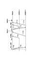
- FIGS. 6 to 8 show timings of communication of polling requests and response data in a plurality of continuous cycles.
- the number n indicating the number of each cycle is an integer.
- the length of each cycle is 100 ms.
- FIG. 6 shows communication in a case where response data is always received in the same cycle as the cycle in which the polling request is transmitted.
- the timing signal is output from the timer 102
- the (n-1) th cycle starts.
- the receiving terminal 10 transmits the polling request P10 to the transmitting terminal 20 (Step S110).
- the transmitting terminal 20 receives the polling request P10 (Step S205).
- the transmitting terminal 20 transmits the response data D10 to the receiving terminal 10 (Step S215).
- the receiving terminal 10 receives the response data D10 (Step S120). After the response data D10 is received, the control circuit 101 waits for a timing signal output from the timer 102 in the (n-1) th cycle.
- the receiving terminal 10 transmits the polling request P11 to the transmitting terminal 20 (Step S110).
- the transmitting terminal 20 receives the polling request P11 (Step S205).
- the transmitting terminal 20 transmits the response data D11 to the receiving terminal 10 (Step S215).
- the receiving terminal 10 receives the response data D11 (Step S120). After the response data D11 is received, the control circuit 101 waits for a timing signal output from the timer 102 in the n-th cycle.
- the (n + 1) th cycle starts. At that time, the receiving terminal 10 transmits the polling request P12 to the transmitting terminal 20 (Step S110). Thereafter, the same operation as described above is repeated.
- the transmitting terminal 20 receives the polling request P12 and transmits the response data D12 to the receiving terminal 10 (Step S205 and Step S215). In the (n + 1) -th cycle, the receiving terminal 10 receives the response data D12 (Step S120).
- the receiving terminal 10 transmits a polling request P13 to the transmitting terminal 20 (Step S110).
- the transmitting terminal 20 receives the polling request P13 and transmits the response data D13 to the receiving terminal 10 (Step S205 and Step S215).
- the receiving terminal 10 receives the response data D13 (Step S120).
- the processing load of the processing circuit 203 differs for each response data, and the timing at which the response data is stored in the storage medium 202 differs in each cycle.
- the processing load of the processing circuit 103 also differs for each response data. To simplify the description, it is assumed that the processing load of the processing circuit 103 is constant.
- the receiving terminal 10 does not immediately transmit the next polling request. In the transmission cycle, the receiving terminal 10 stops transmitting the polling request. The receiving terminal 10 transmits a polling request to the transmitting terminal 20 in a cycle next to the cycle in which the reception of the response data is completed. That is, the receiving terminal 10 transmits a polling request to the transmitting terminal 20 in the next cycle of the transmission cycle.
- FIG. 7 shows communication in a case where no response data is received in the same cycle as the polling request is transmitted.
- the communication in the (n-1) th cycle is the same as the communication in the (n-1) th cycle shown in FIG.
- the receiving terminal 10 transmits the polling request P11 to the transmitting terminal 20 (Step S110).
- the transmitting terminal 20 receives the polling request P11 (Step S205).
- the control circuit 201 waits until response data that can be transmitted is stored in the storage medium 202 (step S210).
- the processing circuit 203 cannot complete the processing of the response data within the n-th cycle.
- the control circuit 101 waits for reception of response data (step S120). While the control circuit 101 is waiting for the response data, the timing signal is output from the timer 102, and the (n + 1) th cycle is started. In the (n + 1) th cycle, the control circuit 101 continuously waits for reception of the response data (step S120).
- the transmitting terminal 20 transmits the response data D11 to the receiving terminal 10 (Step S215).
- the receiving terminal 10 receives the response data D11 (Step S120).
- the control circuit 101 waits for a timing signal output from the timer 102 in the (n + 1) th cycle.
- the (n + 2) th cycle starts.
- the receiving terminal 10 transmits the polling request P12 to the transmitting terminal 20 (Step S110).
- the receiving terminal 10 receives the response data D10 from the transmitting terminal 20.
- the receiving terminal 10 transmits the polling request P11 to the transmitting terminal 20.
- the receiving terminal 10 receives the response data D11 from the transmitting terminal 20.
- the receiving terminal 10 transmits the polling request P12 to the transmitting terminal 20.
- FIG. 8 shows communication in a case where no response data is received in the same cycle as the polling request is transmitted. 7 and 8 are different in processing time of specific response data in the transmitting terminal 20.
- the communication in the (n-1) th cycle is the same as the communication in the (n-1) th cycle shown in FIGS.
- the communication in the n-th cycle is the same as the communication in the n-th cycle shown in FIG.
- the processing circuit 203 cannot complete the processing of the response data within the n-th cycle. Further, the processing circuit 203 cannot complete the processing of the response data within the (n + 1) th cycle.
- step S120 the control circuit 101 waits for reception of response data (step S120). While the control circuit 101 is waiting for the response data, the timing signal is output from the timer 102, and the (n + 2) th cycle is started. In the (n + 2) -th cycle, the control circuit 101 continuously waits for reception of the response data (step S120).
- the transmitting terminal 20 transmits the response data D11 to the receiving terminal 10 (Step S215).
- the receiving terminal 10 receives the response data D11 (Step S120).
- the control circuit 101 waits for a timing signal output from the timer 102.
- the receiving terminal 10 receives the response data D10 from the transmitting terminal 20.
- the receiving terminal 10 transmits the polling request P11 to the transmitting terminal 20.
- the receiving terminal 10 receives the response data D11 from the transmitting terminal 20.
- the receiving terminal 10 transmits the polling request P12 to the transmitting terminal 20.
- the receiving terminal 10 delays receiving the response data.
- the reason why the reception of the response data is delayed is not limited to the processing load of the processing circuit 203 of the transmitting terminal 20.
- reception of response data may be delayed.
- the number of routers (hop count) on a route selected in the network increases and communication delay accumulates, reception of response data may be delayed.
- packet loss occurs. The reception of response data may be delayed due to the occurrence of packet loss.
- the control circuit 101 causes the communication device 100 to transmit the polling request to the transmission terminal 20 in a cycle following the cycle in which the reception of the response data is completed. This operation does not depend on whether or not the response data is received in the same cycle as the cycle in which the polling request is transmitted (transmission cycle). Therefore, control for transmitting a polling request can be simplified.
- the receiving terminal 10 can periodically acquire the response data.
- the control circuit 101 causes the communication device 100 to stop transmitting the polling request in the cycle following the transmission cycle. Therefore, the receiving terminal 10 can suppress transmission of useless polling requests.
- the receiving terminal 10 transmits a polling request to display the response data at regular intervals or to output the response data as a log at regular intervals. If the interval for outputting the response data is much longer than the interval for receiving the response data, the receiving terminal 10 needs to buffer a large amount of data. For example, when n pieces of response data are received every n cycles and one piece of response data is output from the receiving terminal 10 every one cycle, buffering of the n pieces of response data is necessary. The above number n is 2 or more.
- the receiving terminal 10 transmits the polling request to the transmitting terminal 20 at the same interval as the output period of the response data. Therefore, in the receiving terminal 10, the capacity of the data buffer rig can be minimized.
- receiving terminal 10 shown in FIG. 2 is changed to receiving terminal 11 shown in FIG. 9, and transmitting terminal 20 shown in FIG. 3 is changed to transmitting terminal 21 shown in FIG. You.
- FIG. 9 shows the configuration of the receiving terminal 11. The description of the same configuration as that shown in FIG. 2 is omitted.
- the receiving terminal 11 has an operation unit 104 and a display 105 in addition to the configuration shown in FIG.
- the image data is transmitted from the transmission terminal 21 as response data.
- the communication device 100 receives the image data from the transmission terminal 21 and outputs the image data to the control circuit 101.
- the control circuit 101 outputs the received image data to the processing circuit 103.
- the processing circuit 103 processes the image data and outputs the image data to the display 105.
- the control circuit 101 outputs image data to the display 105 via the processing circuit 103.
- the control circuit 101 causes the display 105 to display images based on the received image data at intervals based on the frame rate.
- the control circuit 101 causes the communication device 100 to transmit the polling request to the transmission terminal 21 at the transmission timing.
- the transmission timing is a timing at which an interval based on the frame rate has elapsed from the timing at which the polling request was transmitted.
- the transmission timing is included in a cycle next to a cycle in which the polling request is transmitted.
- the operation device 104 is a user interface.
- the operating device 104 includes at least one of a button, a switch, a key, a mouse, a joystick, a touchpad, a trackball, and a touch panel.
- the user can specify the frame rate by operating the operation device 104.
- the operation device 104 receives a frame rate specified by the user, and outputs information on the frame rate to the control circuit 101.
- the display 105 (monitor) is a liquid crystal display or an organic EL (Electro Luminescence) display.
- the operation device 104 and the display 105 may be configured as a touch panel.
- the display 105 displays images at intervals based on the frame rate based on the image data output from the processing circuit 103. That is, the display 105 displays moving images at intervals based on the frame rate.
- the display frame rate on the receiving terminal 11 indicates the number of frames of an image displayed in one second.
- the reciprocal of the frame rate is the period.
- the operation device 104 is not essential for the receiving terminal 11.
- the operating device 104 may be arranged outside the receiving terminal 11, and frame rate information may be input from the operating device 104 to the receiving terminal 11.
- the display 105 is not essential for the receiving terminal 11.
- the display 105 may be arranged outside the receiving terminal 11 and image data may be output from the receiving terminal 11 to the display 105.
- FIG. 10 shows the configuration of the transmitting terminal 21. The description of the same configuration as that shown in FIG. 3 is omitted.
- the transmission terminal 21 has an image sensor 204 in addition to the configuration shown in FIG.
- the image sensor 204 is an image sensor.
- the image sensor 204 captures an image of a subject and generates image data.
- the image sensor 204 generates image data at intervals based on the frame rate.
- the frame rate of imaging in the transmission terminal 21 indicates the number of frames of an image generated in one second.
- the frame rate of imaging at the transmitting terminal 21 is the same as the frame rate of display at the receiving terminal 11.
- the imaging frame rate may be different from the display frame rate.
- the image sensor 204 outputs the generated image data to the processing circuit 203.
- the processing circuit 203 processes the image data at intervals based on the frame rate.
- the processing circuit 203 outputs the processed image data to the storage medium 202. Since the processing load of the processing circuit 203 differs for each image data, the interval at which the processing circuit 203 outputs the image data to the storage medium 202 is not always constant.
- the storage medium 202 stores the image data output from the processing circuit 203.
- the control circuit 201 reads out the image data from the storage medium 202 based on the polling request output from the communication device 200.
- the control circuit 201 outputs the image data to the communication device 200.
- the communication device 200 transmits the image data output from the control circuit 201 to the receiving terminal 11 as response data.
- the receiving terminal 11 executes the processing shown in FIG. 11 instead of the processing shown in FIG. FIG. 11 shows a procedure of a process executed by the receiving terminal 11.
- the operation of the receiving terminal 11 will be described with reference to FIG. Description of the same processing as the processing shown in FIG. 4 will be omitted.
- the user operates the operating device 104 to specify the frame rate.
- the operation device 104 outputs information of the frame rate designated by the user to the control circuit 101.
- the control circuit 101 detects the frame rate specified by the user based on the information output from the operation device 104 (step S130).
- step S130 the control circuit 101 calculates a polling request transmission interval based on the frame rate (step S131).
- the polling request transmission interval is the reciprocal of the frame rate.
- step S131 the control circuit 101 sets the calculated transmission interval in the timer 102 (step S132).
- the timer 102 outputs a timing signal at a set transmission interval.
- step S132 the process in step S100 is performed.
- step S120 when the control circuit 101 determines that response data, that is, image data, has been received from the transmission terminal 21, the control circuit 101 outputs the received image data to the processing circuit 103.
- the processing circuit 103 processes the image data and outputs the image data to the display 105.
- the display 105 displays an image based on the image data (Step S133). After step S133, the process in step S100 is executed.
- the display 105 displays the image at intervals based on the frame rate. If the reception of the image data is not completed in the transmission cycle, the control circuit 101 may cause the display 105 to display an image based on the previously received image data again. When image data reception is not completed in two or more consecutive cycles, the display 105 repeatedly displays an image based on one image data.
- Steps S130 to S132 are not essential. Therefore, the transmission interval of the polling request may be fixed.
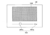
- FIG. 12 shows a screen of the display 105.
- the display 105 displays the image 1050 and the frame rate information 1051.
- Image 1050 is displayed based on the image data received from transmitting terminal 21.
- the frame rate information 1051 includes an instruction section 1051a and a value 1051b.
- the user specifies the frame rate by operating the instruction unit 1051a.
- the value 1051b indicates the frame rate specified by the user.
- the screen of the display 105 is not limited to the example shown in FIG.
- the transmitting terminal 21 executes the processing shown in FIG.
- the operation of the transmitting terminal 21 is the same as the operation of the transmitting terminal 20 of the first embodiment, and a description thereof will be omitted.
- the receiving terminal 11 when the image data is received in the same cycle as the cycle in which the polling request is transmitted, the receiving terminal 11 can periodically acquire the image data.
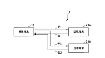
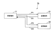
- FIG. 13 shows the configuration of a communication system 1a according to the third embodiment of the present invention.
- the communication system 1a illustrated in FIG. 13 includes a receiving terminal 11, a transmitting terminal 21a, and a transmitting terminal 21b.
- the configuration of the receiving terminal 11 is the same as the configuration shown in FIG.
- Each configuration of transmitting terminal 21a and transmitting terminal 21b is the same as the configuration shown in FIG.
- the receiving terminal 11 transmits the polling request P1 to the transmitting terminal 21a, and transmits the polling request P2 to the transmitting terminal 21b.
- the transmitting terminal 21a receives the polling request P1 and transmits response data D1 to the receiving terminal 11.
- the transmitting terminal 21b receives the polling request P2 and transmits the response data D2 to the receiving terminal 11.
- the receiving terminal 11 may include a communication device that communicates with the transmission terminal 21a and a communication device that communicates with the transmission terminal 21b.
- the communication system 1a only needs to have two or more transmitting terminals.
- the communication system 1a has two transmitting terminals.
- the communication system 1a may have three or more transmitting terminals.
- the control circuit 101 of the receiving terminal 11 causes the communication device 100 to transmit a polling request to all of the two or more transmitting terminals in at least one of two or more consecutive periods.
- the control circuit 101 causes the communication device 100 to transmit a polling request to all of the two or more transmission terminals at the transmission timing.
- the transmission cycle is a cycle at which the polling request is transmitted.
- the transmission timing is a timing at which an interval based on the frame rate has elapsed from the timing at which the polling request was transmitted.
- the transmission timing is included in a cycle next to a cycle in which the polling request is transmitted. If the reception of at least one image data by the two or more transmission terminals is not completed in the transmission cycle, the control circuit 101 causes the communication device 100 to stop transmitting the polling request and receive the image data in the cycle following the transmission cycle. Wait for.
- the control circuit 101 causes the communication device 100 to transmit a polling request to all of the two or more transmission terminals in a cycle following the cycle in which the reception of the last image data among all the image data of the two or more transmission terminals is completed.
- the last image data is the last received image data among all the image data received from all of the two or more transmitting terminals in one transmission cycle.
- the control circuit 101 causes the display 105 to simultaneously display two or more images based on the two or more image data received from all of the two or more transmitting terminals at intervals based on the frame rate.
- the receiving terminal 11 may have two or more displays. Two or more displays may simultaneously display different images, respectively.
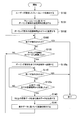
- the receiving terminal 11 executes the processing shown in FIG. 14 instead of the processing shown in FIG. FIG. 14 shows a procedure of processing executed by the receiving terminal 11.
- the operation of the receiving terminal 11 will be described with reference to FIG. Description of the same processing as the processing shown in FIG. 11 will be omitted.
- step S105 when the control circuit 101 determines that the timing signal has been received from the timer 102, the control circuit 101 causes the communication device 100 to transmit a polling request to the transmission terminal 21a and the transmission terminal 21b. Thereby, the communication device 100 transmits a polling request to the transmitting terminal 21a and the transmitting terminal 21b (Step S110a). After step S110a, the process in step S115 is performed.
- step S110a the control circuit 101 causes the communication device 100 to simultaneously transmit a polling request to the transmitting terminal 21a and the transmitting terminal 21b. If each transmitting terminal can transmit the response data (image data) in the period in which the polling request is transmitted, the receiving terminal 11 needs to receive the response data from each transmitting terminal in that period. As long as such a condition is satisfied, the control circuit 101 may cause the communication device 100 to sequentially transmit the polling request to the transmitting terminal 21a and the transmitting terminal 21b.
- control circuit 101 determines in step S115 that the termination has not been instructed, the control circuit 101 monitors the communication device 100 and determines whether or not image data has been received from the transmission terminal 21a and the transmission terminal 21b. I do.
- the control circuit 101 causes the communication device 100 to receive the image data from the transmission terminal 21a and the transmission terminal 21b (step S120a).
- control circuit 101 determines that the response data has not been received from at least one of the transmitting terminal 21a and the transmitting terminal 21b in step S120a, the process in step S115 is executed. Until response data is received from both transmitting terminal 21a and transmitting terminal 21b, control circuit 101 executes the processing in each of step S115 and step S120a, and waits for reception of response data.
- the control circuit 101 determines in step S120a that response data has been received from the transmitting terminal 21a and the transmitting terminal 21b, the control circuit 101 outputs two response data received from the two transmitting terminals to the processing circuit 103. . That is, the control circuit 101 outputs two pieces of image data to the processing circuit 103.
- the processing circuit 103 processes the two image data and generates display data including the two image data (Step S140). For example, in step S140, the processing circuit 103 generates display data for displaying two images in a state where the two images are arranged in the horizontal direction or the vertical direction.
- step S140 the processing circuit 103 outputs the generated display data to the display 105.
- the display 105 displays two images simultaneously based on the display data output from the processing circuit 103 (step S141).
- step S141 the control circuit 101 causes the display 105 to simultaneously display two images based on the two image data received from the transmission terminal 21a and the transmission terminal 21b.
- step S100 the process in step S100 is executed.
- the display 105 displays two images simultaneously at intervals based on the frame rate.
- the transmitting terminal 21a and the transmitting terminal 21b execute the processing shown in FIG.
- the operation of each of the transmitting terminal 21a and the transmitting terminal 21b is the same as the operation of the transmitting terminal 20 of the first embodiment, and a description thereof will be omitted.
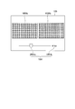
- FIG. 15 shows a screen of the display 105.
- the display 105 displays an image 1050a and an image 1050b.
- Image 1050a is displayed based on the image data received from transmitting terminal 21a.
- Image 1050b is displayed based on the image data received from transmitting terminal 21b.
- the screen of the display 105 is not limited to the example shown in FIG. In FIG. 15, the image 1050a and the image 1050b are arranged in the horizontal direction. The image 1050a and the image 1050b may be arranged in the vertical direction.
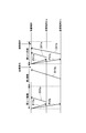
- FIGS. 16 to 18 show timings of polling request and response data communication in a plurality of continuous cycles.
- the number n indicating the number of each cycle is an integer.
- the length of each cycle is 100 ms.
- FIG. 16 shows communication in a case where response data is always received in the same cycle as the cycle in which the polling request is transmitted.
- the timing signal is output from the timer 102
- the (n-1) th cycle starts.
- the receiving terminal 11 transmits the polling request P10a to the transmitting terminal 21a, and transmits the polling request P10b to the transmitting terminal 21b (Step S110a).
- the transmitting terminal 21a receives the polling request P10a (Step S205).
- the transmitting terminal 21a transmits the response data D10a to the receiving terminal 11 (Step S215).
- transmitting terminal 21b receives polling request P10b and transmits response data D10b to receiving terminal 11 (steps S205 and S215).
- the receiving terminal 11 receives the response data D10a and the response data D10b (Step S120a).
- the display 105 simultaneously displays an image based on the response data D10a and an image based on the response data D10b (step S141).
- the control circuit 101 waits for a timing signal output from the timer 102 in the (n-1) th cycle.
- the receiving terminal 11 transmits the polling request P11a to the transmitting terminal 21a, and transmits the polling request P11b to the transmitting terminal 21b (Step S110a).
- the transmitting terminal 21a receives the polling request P11a (Step S205).
- the transmitting terminal 21a transmits the response data D11a to the receiving terminal 11 (Step S215).
- the transmitting terminal 21b receives the polling request P11b and transmits response data D11b to the receiving terminal 11 (Step S205 and Step S215).
- the receiving terminal 11 receives the response data D11a and the response data D11b (Step S120a).
- the display 105 simultaneously displays an image based on the response data D11a and an image based on the response data D11b (step S141).
- the control circuit 101 waits for a timing signal output from the timer 102 in the n-th cycle.
- the (n + 1) th cycle starts.
- the receiving terminal 11 transmits the polling request P12a to the transmitting terminal 21a, and transmits the polling request P12b to the transmitting terminal 21b (Step S110a).
- the transmitting terminal 21a receives the polling request P12a and transmits the response data D12a to the receiving terminal 11 (Step S205 and Step S215).
- the transmitting terminal 21b receives the polling request P12b and transmits the response data D12b to the receiving terminal 11 (Step S205 and Step S215).
- the receiving terminal 11 receives the response data D12a and the response data D12b (Step S120a).
- the display 105 simultaneously displays an image based on the response data D12a and an image based on the response data D12b (step S141).
- the receiving terminal 11 transmits the polling request P13a to the transmitting terminal 21a and transmits the polling request P13b to the transmitting terminal 21b (Step S110a).
- the transmitting terminal 21a receives the polling request P13a and transmits the response data D13a to the receiving terminal 11 (Step S205 and Step S215).
- the transmitting terminal 21b receives the polling request P13b and transmits the response data D13b to the receiving terminal 11 (Step S205 and Step S215).
- the receiving terminal 11 receives the response data D13a and the response data D13b (Step S120a).
- the display 105 simultaneously displays an image based on the response data D13a and an image based on the response data D13b (step S141).
- the receiving terminal 11 Even if response data is received from the transmitting terminal 21a and the transmitting terminal 21b in the same period as the period in which the polling request is transmitted (transmission period), the receiving terminal 11 does not immediately transmit the next polling request. In the transmission cycle, the receiving terminal 11 stops transmitting the polling request. In the next cycle after the cycle in which the response data is received from the transmitting terminal 21a and the transmitting terminal 21b, the receiving terminal 11 transmits a polling request to the transmitting terminal 21a and the transmitting terminal 21b.
- response data is received from the transmitting terminal 21a.
- Response data need not be received in the order in which the polling requests were sent.
- the receiving terminal 11 has a communication device that communicates with the transmitting terminal 21a and a communication device that communicates with the transmitting terminal 21b, the receiving terminal 11 not only transmits the polling request at the same time, It is also possible to receive response data at the same time.
- the control circuit 101 causes the communication device 100 to transmit the polling request to the transmission terminal 21a and the transmission terminal 21b at the transmission timing in a period following the period in which the response data is received from the transmission terminal 21b.
- the transmission timing is a timing at which an interval based on the frame rate has elapsed from the timing at which the polling request was transmitted to the transmission terminal 21a and the transmission terminal 21b.
- FIG. 17 shows communication in a case where response data is not received from one transmitting terminal in the same cycle as the polling request is transmitted.
- the timing signal is output from the timer 102
- the (n-1) th cycle starts.
- the receiving terminal 11 transmits the polling request P10a to the transmitting terminal 21a, and transmits the polling request P10b to the transmitting terminal 21b (Step S110a).
- the transmitting terminal 21a receives the polling request P10a (Step S205).
- the transmitting terminal 21a transmits the response data D10a to the receiving terminal 11 (Step S215).
- the transmitting terminal 21b receives the polling request P10b (Step S205).
- the control circuit 201 of the transmitting terminal 21b waits until response data that can be transmitted is stored in the storage medium 202 (step S210).
- the processing circuit 203 of the transmitting terminal 21b cannot complete the processing of the response data within the (n-1) th cycle.
- the receiving terminal 11 receives the response data D10a (Step S120a).
- the control circuit 101 waits for the reception of the response data (step S120a). While the control circuit 101 is waiting for the response data, the timing signal is output from the timer 102, and the n-th cycle is started. In the n-th cycle, the control circuit 101 continuously waits for reception of the response data transmitted from the transmitting terminal 21b (Step S120a).
- the transmitting terminal 21b transmits the response data D10b to the receiving terminal 11 (Step S215).
- the receiving terminal 11 receives the response data D10b (Step S120a).
- the display 105 simultaneously displays an image based on the response data D10a and an image based on the response data D10b (step S141).
- the control circuit 101 waits for a timing signal output from the timer 102 in the n-th cycle.
- the (n + 1) th cycle starts.
- the receiving terminal 11 transmits the polling request P11a to the transmitting terminal 21a, and transmits the polling request P11b to the transmitting terminal 21b (Step S110a).
- the transmitting terminal 21a receives the polling request P11a and transmits response data D11a to the receiving terminal 11 (Step S205 and Step S215).
- the transmitting terminal 21b receives the polling request P11b and transmits the response data D11b to the receiving terminal 11 (Step S205 and Step S215).
- the receiving terminal 11 receives the response data D11a and the response data D11b (Step S120a).
- the display 105 simultaneously displays an image based on the response data D11a and an image based on the response data D11b (step S141).
- the receiving terminal 11 receives the response data D10a from the transmitting terminal 21a.
- the receiving terminal 11 receives the response data D10b from the transmitting terminal 21b.
- the receiving terminal 11 transmits the polling request P11a to the transmitting terminal 21a, and transmits the polling request P11b to the transmitting terminal 21b.
- FIG. 18 shows communication in a case where response data is not received from one transmitting terminal in the same cycle as the polling request is transmitted. 17 and FIG. 18, the processing time of specific response data in the transmitting terminal 21a is different.
- the timing signal is output from the timer 102, the (n-1) th cycle starts.
- the receiving terminal 11 transmits the polling request P10a to the transmitting terminal 21a, and transmits the polling request P10b to the transmitting terminal 21b (Step S110a).
- the transmitting terminal 21a receives the polling request P10a (Step S205).
- the control circuit 201 of the transmitting terminal 21a waits until response data that can be transmitted is stored in the storage medium 202 (step S210).
- the processing circuit 203 of the transmitting terminal 21a cannot complete the processing of the response data within the (n-1) th cycle.
- the transmitting terminal 21b receives the polling request P10b (Step S205).
- the control circuit 201 of the transmitting terminal 21b waits until response data that can be transmitted is stored in the storage medium 202 (step S210).
- the processing circuit 203 of the transmitting terminal 21b cannot complete the processing of the response data within the (n-1) th cycle.
- step S120a since the response data is not received from the transmission terminal 21a and the transmission terminal 21b, the control circuit 101 waits for the reception of the response data (step S120a). While the control circuit 101 is waiting for the response data, the timing signal is output from the timer 102, and the n-th cycle is started. In the n-th cycle, the control circuit 101 continuously waits for reception of the response data transmitted from the transmitting terminal 21a and the transmitting terminal 21b (Step S120a).
- the transmission terminal 21a transmits response data D10a to the reception terminal 11 (step S215).
- the transmitting terminal 21b transmits the response data D10b to the receiving terminal 11 (Step S215).
- the receiving terminal 11 receives the response data D10a and the response data D10b (Step S120a).
- the display 105 simultaneously displays an image based on the response data D10a and an image based on the response data D10b (step S141). After the response data D10b is received, the control circuit 101 waits for a timing signal output from the timer 102 in the n-th cycle.
- the receiving terminal 11 may acquire the image data periodically. And images can be displayed periodically. For example, the user can simultaneously check two images based on two optical images formed by two optical systems having parallax. Alternatively, the user can simultaneously confirm two images acquired by simultaneously photographing one subject from two viewpoints.
- the control circuit 101 determines a communication environment between the receiving terminal 11 and the transmitting terminal 21a. Further, the control circuit 101 determines the communication environment between the receiving terminal 11 and the transmitting terminal 21b. When the control circuit 101 determines that the communication environment has deteriorated, the control circuit 101 makes the cycle at which the polling request is transmitted longer than the cycle before the communication environment deteriorates.
- the control circuit 201 of the transmitting terminal 21a determines the communication environment between the receiving terminal 11 and the transmitting terminal 21a.
- the processing circuit 203 data compression circuit
- the communication device 200 transmits the compressed image data to the receiving terminal 11 based on the polling request.
- the control circuit 201 determines that the communication environment has deteriorated, the control circuit 201 sets the compression ratio of the image data higher than the compression ratio before the communication environment deteriorated.
- the transmitting terminal 21b performs the same processing as the processing performed by the transmitting terminal 21a.
- the receiving terminal 11 executes the process shown in FIG. 19 instead of the process shown in FIG. FIG. 19 shows a procedure of a process executed by the receiving terminal 11.
- the operation of the receiving terminal 11 will be described with reference to FIG. Description of the same processing as the processing shown in FIG. 14 will be omitted.
- the control circuit 201 of each of the transmission terminal 21a and the transmission terminal 21b divides the response data into a plurality of data and generates a packet including each data.
- the control circuit 201 causes the communication device 200 to sequentially transmit a plurality of packets to the receiving terminal 11.
- the control circuit 101 of the receiving terminal 11 causes the communication device 100 to sequentially receive a plurality of packets from the transmitting terminal 21a or the transmitting terminal 21b.
- step S142 determines a communication environment based on the response data reception status. For example, in step S142, the control circuit 101 determines a communication environment based on the packet loss rate. If the packet loss rate is equal to or less than the predetermined threshold, the control circuit 101 determines that the communication environment is good. If the packet loss rate is larger than the predetermined threshold, the control circuit 101 determines that the communication environment has deteriorated.
- the method for determining the communication environment is not limited to the above method.
- step S142 the control circuit 101 determines the first communication environment between the receiving terminal 11 and the transmitting terminal 21a, and determines the second communication environment between the receiving terminal 11 and the transmitting terminal 21b. When both the first communication environment and the second communication environment are good, the control circuit 101 determines that the communication environment is good. When at least one of the first communication environment and the second communication environment deteriorates, the control circuit 101 determines that the communication environment has deteriorated.
- step S105 determines in step S142 that the communication environment is good. If the control circuit 101 determines in step S142 that the communication environment is good, the process in step S105 is executed. When the control circuit 101 determines in step S142 that the communication environment has deteriorated, the control circuit 101 lengthens the transmission interval set in the timer 102 (step S143). After step S143, the process in step S105 is performed.
- control circuit 101 may shorten the transmission interval set in the timer 102 in a step not shown in FIG.
- the control circuit 101 may change the frame rate of the image displayed on the display 105. For example, when the transmission interval becomes longer, the control circuit 101 reduces the frame rate. For example, when the transmission interval is shortened, the control circuit 101 increases the frame rate.
- the transmitting terminal 21a and the transmitting terminal 21b execute the processing shown in FIG. 20 instead of the processing shown in FIG. FIG. 20 shows a procedure of processing executed by the transmitting terminal 21a and the transmitting terminal 21b.
- the operation of the transmitting terminal 21a and the transmitting terminal 21b will be described with reference to FIG. A description of the same processing as the processing shown in FIG. 5 will be omitted.
- the transmitting terminal to which no code is given is one of the transmitting terminal 21a and the transmitting terminal 21b.
- the compression ratio of the image data in the processing circuit 203 of the transmitting terminal is set to a predetermined value.
- the control circuit 101 of the receiving terminal 11 causes the communication device 100 to transmit a retransmission request to the transmitting terminal.
- the control circuit 201 of the transmitting terminal causes the communication device 200 to receive the retransmission request from the receiving terminal 11.
- the control circuit 201 causes the communication device 200 to transmit a packet corresponding to the retransmission request to the receiving terminal 11.
- step S240 the control circuit 201 determines a communication environment between the receiving terminal 11 and the transmitting terminal. For example, in step S240, the control circuit 201 calculates the reception interval of the retransmission request or the reception frequency of the retransmission request. When the reception interval of the retransmission request is equal to or longer than a predetermined time, or when the reception frequency of the retransmission request is equal to or lower than a predetermined value, the control circuit 201 determines that the communication environment is good.
- the control circuit 201 determines that the communication environment has deteriorated.
- the method for determining the communication environment is not limited to the above method.
- step S205 determines in step S240 that the communication environment is good. If the control circuit 201 determines in step S240 that the communication environment has deteriorated, the control circuit 201 increases the compression ratio of the image data set in the processing circuit 203 (step S241). After step S241, the process in step S205 is performed.
- control circuit 201 may lower the compression ratio of the image data set in the processing circuit 203 in a step not shown in FIG.
- the communication environment is determined in both the receiving terminal 11 and the transmitting terminal.
- the communication environment may be determined only by the receiving terminal 11 or the transmitting terminal.
- the receiving terminal 11 determines that the communication environment has deteriorated, the transmission interval of the polling request becomes longer.
- the transmitting terminal determines that the communication environment has deteriorated, the compression ratio of the image data increases. Therefore, there is a possibility that the receiving terminal 11 can recover the periodic information acquisition.
- FIG. 21 shows a configuration of a communication system 1b according to the fourth embodiment of the present invention.
- the communication system 1b illustrated in FIG. 21 includes a receiving terminal 11, a transmitting terminal 21, and a transmitting terminal 22.
- the configuration of the receiving terminal 11 is the same as the configuration shown in FIG.
- the configuration of transmitting terminal 21 is the same as the configuration shown in FIG.
- the receiving terminal 11 transmits the polling request P1 to the transmitting terminal 21, and transmits the polling request P3 to the transmitting terminal 22.
- the transmitting terminal 21 receives the polling request P1 and transmits the response data D1 to the receiving terminal 11.
- the transmitting terminal 22 receives the polling request P3 and transmits response data D3 to the receiving terminal 11.
- the receiving terminal 11 may include a communication device that communicates with the transmission terminal 21 and a communication device that communicates with the transmission terminal 22.
- FIG. 22 shows the configuration of the transmitting terminal 22 (second transmitting terminal). The description of the same configuration as that shown in FIG. 3 is omitted.
- the transmission terminal 22 has a sensor in addition to the configuration shown in FIG.
- the sensor is an infrared camera 205.
- the infrared camera 205 captures an image of a subject and generates infrared image data.
- the infrared camera 205 generates infrared image data at intervals based on the frame rate.
- the infrared camera 205 outputs the infrared image data to the processing circuit 203.
- the processing circuit 203 processes the infrared image data and outputs the abnormal data generated by the processing to the storage medium 202. For example, the processing circuit 203 generates a temperature distribution based on the infrared image data. The processing circuit 203 determines whether or not there is an abnormality based on the temperature distribution, and generates abnormality data indicating the result of the determination. For example, when an area where the temperature is higher than the predetermined value and the area is larger than the predetermined value exists in the infrared image, the abnormal data indicates that there is an abnormality. If the region does not exist in the infrared image, the abnormal data indicates that there is no abnormality. The processing circuit 203 may learn the past temperature distribution and distinguish small animals from humans.
- the processing circuit 203 may generate abnormal data indicating whether a human exists in the infrared image.
- the infrared camera 205 periodically generates infrared image data at predetermined intervals, and the processing circuit 203 processes the infrared image data periodically at predetermined intervals.
- the storage medium 202 stores the abnormal data output from the processing circuit 203 as sensor data.
- the control circuit 201 reads abnormal data from the storage medium 202 based on the polling request output from the communication device 200.
- the control circuit 201 outputs the abnormal data to the communication device 200.
- the communication device 200 (third communication device) transmits the abnormal data output from the control circuit 201 to the receiving terminal 11 as response data.
- the sensor of the transmitting terminal 22 is not limited to the infrared camera 205.
- the transmitting terminal 22 may include a temperature sensor that detects a temperature.
- the transmitting terminal 22 may include a position sensor that detects the position of the transmitting terminal 22.
- the position sensor is a GPS (Global Positioning System) sensor.
- the control circuit 101 of the receiving terminal 11 causes the communication device 100 to transmit a polling request to the transmitting terminal 21 and the transmitting terminal 22 in at least one of two or more consecutive periods.
- the control circuit 101 sends a polling request to the communication device 100 at the transmission timing. 22.
- the transmission cycle is a cycle at which the polling request is transmitted.
- the transmission timing is a timing at which an interval based on the frame rate has elapsed from the timing at which the polling request was transmitted.
- the control circuit 101 stops the transmission of the polling request to the communication device 100 in a cycle subsequent to the transmission cycle, and outputs at least one of the image data and the sensor data. Wait for reception.
- the control circuit 101 causes the communication device 100 to transmit the polling request to the transmission terminal 21 and the transmission terminal 22 at the transmission timing in a period following the period in which the reception of the image data and the sensor data is completed.
- the control circuit 101 causes the display 105 to simultaneously display the image and the received sensor data at intervals based on the frame rate.
- the control circuit 101 When the reception of the response data is not completed in the standby period, the control circuit 101 causes the communication device 100 to transmit the polling request to the transmitting terminal 21 and the transmitting terminal 22 in a cycle following the standby period.
- the waiting period includes at least two continuous cycles of the two or more cycles. If the reception of the response data is not completed in two or more consecutive waiting periods, the control circuit 101 causes the communication device 100 to terminate the communication with the transmission terminal 21 and the communication with the transmission terminal 22.
- the case where the reception of the response data is not completed in the standby period includes the case where the response data is not received in the standby period.
- the control circuit 101 causes the communication device 100 to transmit a polling request to the transmission terminal 21 and the transmission terminal 22 in a cycle following the standby period. For example, when the reception of the image data is not completed in any of at least two periods included in the standby period, the control circuit 101 sends a polling request to the communication device 100 to the transmission terminal 21 and the transmission terminal 22 in a period subsequent to the standby period. To send to.
- the control circuit 101 sends a polling request to the communication device 100 to the transmission terminal 21 and the transmission terminal 22 in the period subsequent to the standby period. To send to.
- the control circuit 101 causes the communication device 100 to terminate the communication with the transmission terminal 21 and the communication with the transmission terminal 22. For example, when the state that the reception of the image data is not completed in the standby period is continued twice or more, the control circuit 101 causes the communication device 100 to end the communication with the transmission terminal 21 and the communication with the transmission terminal 22. Alternatively, when the state that the reception of the sensor data is not completed in the standby period continues two or more times, the control circuit 101 causes the communication device 100 to end the communication with the transmission terminal 21 and the communication with the transmission terminal 22.
- the communication device 100 and the communication device 200 wirelessly communicate polling requests and response data.
- the control circuit 101 determines a communication environment between the receiving terminal 11 and the transmitting terminal 21 and determines a communication environment between the receiving terminal 11 and the transmitting terminal 22.
- the control circuit 101 determines that the communication device 100 has terminated the communication with the transmission terminal 21 and that the communication environment between the reception terminal 11 and the transmission terminal 21 has deteriorated, the control circuit 101 The communication channel used for communication with the transmitting terminal 21 is changed, and communication with the transmitting terminal 21 is restarted.
- control circuit 101 determines that the communication device 100 has terminated the communication with the transmission terminal 22 and the communication environment between the reception terminal 11 and the transmission terminal 22 has deteriorated, the control circuit 101 The communication channel used for communication with the transmission terminal 22 is changed, and communication with the transmission terminal 22 is restarted.
- the communication channel (communication frequency) used for communication between the receiving terminal 11 and the transmitting terminal 21 is different from the communication channel (communication frequency) used for communication between the receiving terminal 11 and the transmitting terminal 22. Or the same.
- the control circuit 101 determines that the communication device 100 has terminated the communication with the transmission terminal 21 and that the communication environment between the reception terminal 11 and the transmission terminal 21 has deteriorated, the control circuit 101 The communication frequency used for communication with the transmitting terminal 21 is changed, and communication with the transmitting terminal 21 is restarted.
- control circuit 101 determines that the communication device 100 has terminated the communication with the transmission terminal 22 and the communication environment between the reception terminal 11 and the transmission terminal 22 has deteriorated, the control circuit 101 The communication frequency used for communication with the transmission terminal 22 is changed, and communication with the transmission terminal 22 is restarted.
- the control circuit 101 determines that the communication environment between the reception terminal 11 and the transmission terminal 21 has deteriorated, the control circuit 101 sets a communication channel different from the communication channel used for communication with the transmission terminal 21. It is determined as a new communication channel.
- the control circuit 101 causes the communication device 100 to transmit channel information indicating a new communication channel to the transmission terminal 21. After the channel information is transmitted, the control circuit 101 causes the communication device 100 to terminate communication with the transmission terminal 21 and causes the communication device 100 to resume communication with the transmission terminal 21 using a new communication channel.
- the control circuit 101 executes the same processing as the above processing for communication with the transmitting terminal 22.
- the control circuit 201 causes the communication device 200 to end the communication with the reception terminal 11 and indicates the communication device 200 with the channel information.
- the communication with the receiving terminal 11 is restarted using the new communication channel.
- the control circuit 101 may cause the communication device 100 to transmit a communication channel change request to the transmission terminal 21.
- the control circuit 101 causes the communication device 100 to terminate the communication with the transmission terminal 21, and the communication device 100 The communication with the transmitting terminal 21 is restarted using the new communication channel shown.
- the control circuit 101 may execute the same processing as the above processing for communication with the transmission terminal 22.
- the control circuit 201 sets a communication channel different from the communication channel used for communication with the reception terminal 11 to a new communication channel. To be determined.
- the control circuit 201 causes the communication device 200 to transmit channel information indicating a new communication channel to the receiving terminal 11. After the channel information is transmitted, the control circuit 201 causes the communication device 200 to end communication with the reception terminal 11 and causes the communication device 200 to resume communication with the reception terminal 11 using a new communication channel.
- the control circuit 201 may cause the communication device 200 to transmit to the receiving terminal 11 completion information indicating that the channel change has been completed, without transmitting the channel information indicating the new communication channel to the receiving terminal 11.
- the receiving terminal 11 stores the network identifier of the transmitting terminal 21 or the transmitting terminal 22.
- the receiving terminal 11 searches for a transmitting terminal having the stored network identifier while switching the communication channel, and resumes communication with the transmitting terminal.
- the network identifier includes a Wi-Fi standard SSID (Service @ Set @ ID) or a BSSID (Basic @ Service @ Set @ ID).
- the receiving terminal 11 executes the processing shown in FIGS. 23 and 24 instead of the processing shown in FIG. FIG. 23 and FIG. 24 show the procedure of the process executed by the receiving terminal 11.
- the operation of the receiving terminal 11 will be described with reference to FIGS. Description of the same processing as the processing shown in FIG. 14 will be omitted.
- step S153 If the control circuit 101 determines in step S100 or S115 that termination has been instructed, the process in step S153 is executed. Details of the processing in step S153 will be described later.
- the control circuit 101 determines that the response data has not been received from at least one of the transmission terminal 21 and the transmission terminal 22 in step S120a, the control circuit 101 sets the standby period from the timing at which the polling request was transmitted in step S110a. Is determined (step S150). For example, the waiting period is five cycles.
- the control circuit 101 receives the timing signal from the timer 102 a predetermined number of times, the control circuit 101 determines that the standby period has elapsed.
- step S150 determines in step S150 that the standby period has not elapsed. If the control circuit 101 determines in step S150 that the standby period has not elapsed, the process in step S115 is performed. When the control circuit 101 determines that the standby period has elapsed in step S150, the control circuit 101 determines whether the retry flag is FALSE (step S151).
- the retry flag indicates whether the receiving terminal 11 is retrying the transmission of the polling request.
- the initial value of the retry flag is FALSE.
- the control circuit 101 determines that the retry flag is FALSE in step S151, the control circuit 101 changes the retry flag to TRUE (step S152). After step S152, the process in step S100 is executed.
- the control circuit 101 After the polling request is transmitted to the transmitting terminal 21 and the transmitting terminal 22, the control circuit 101 waits for reception of response data transmitted from each of the transmitting terminal 21 and the transmitting terminal 22. When the waiting period has elapsed without the reception of at least one response data of the transmission terminal 21 and the transmission terminal 22, the control circuit 101 performs a retry of transmission of the polling request.
- control circuit 101 causes the communication device 100 to transmit the polling request to the transmitting terminal 21 and the transmitting terminal 22 again in step S110a.
- step S151 determines that the retry flag is TRUE, the control circuit 101 determines that the reception of the response data has not been completed in two consecutive standby periods. In that case, the control circuit 101 changes the retry flag to FALSE (step S153).
- the control circuit 101 determines the communication environment and determines whether to change the communication channel (step S154). For example, the control circuit 101 determines the communication environment by executing the same processing as the processing in step S142 shown in FIG. When the retry flag is TRUE in step S151 and the communication environment has deteriorated in step S154, the control circuit 101 determines that the reception of the response data is not completed due to the deterioration of the communication environment.
- the control circuit 101 determines in step S154 that the communication with the transmitting terminal 21 Is determined to change the communication channel to use. If the reception of the response data from the transmitting terminal 22 has not been completed and the communication environment between the receiving terminal 11 and the transmitting terminal 22 has deteriorated, the control circuit 101 determines in step S154 that the communication with the transmitting terminal 22 Is determined to change the communication channel to use. If the reason why the reception of the response data is not completed is not the deterioration of the communication environment, the processing illustrated in FIGS. 23 and 24 ends. When the end is instructed in step S100 or step S115 and the determination in step S154 is executed, the processing illustrated in FIGS. 23 and 24 ends.
- step S154 when the control circuit 101 determines that the communication channel is changed, the control circuit 101 causes the communication device 100 to end the communication with the transmission terminal 21 or the transmission terminal 22. Further, the control circuit 101 causes the communication device 100 to change the communication channel used for communication with the transmitting terminal 21 or the transmitting terminal 22 (Step S155).
- step S155 the control circuit 101 causes the communication device 100 to reconnect to the transmission terminal 21 and restart communication with the transmission terminal 21.
- the control circuit 101 causes the communication device 100 to reconnect to the transmission terminal 22 and restart communication with the transmission terminal 22 (step S156).
- step S156 the process in step S130 is performed.
- step S120a when the control circuit 101 determines that response data has been received from the transmission terminal 21 and the transmission terminal 22, the control circuit 101 changes the retry flag to FALSE (step S157).
- the control circuit 101 After the step S157, the control circuit 101 outputs the two response data received from the two transmitting terminals to the processing circuit 103. That is, the control circuit 101 outputs the image data and the sensor data to the processing circuit 103.
- the processing circuit 103 processes the two pieces of response data and generates display data including the two pieces of response data (Step S140b).
- step S140b the processing circuit 103 outputs the generated display data to the display 105.
- the display 105 simultaneously displays the image and the sensor data based on the display data output from the processing circuit 103 (Step S141b).
- the control circuit 101 causes the display 105 to simultaneously display an image based on the image data received from the transmission terminal 21 and sensor data received from the transmission terminal 22.
- step S100 the process in step S100 is executed.
- the display 105 displays the image and sensor data at intervals based on the frame rate. Are displayed at the same time. If the reception of the image data or the sensor data is not completed in the transmission cycle, the control circuit 101 may cause the display 105 to display an image based on the previously received image data or the previously received sensor data again. When the reception of the image data or the sensor data is not completed in two or more consecutive periods, the display 105 repeatedly displays an image based on one image data or one sensor data.
- the receiving terminal 11 ends the communication with the transmitting terminal 21 or the transmitting terminal 22. If the reception of the response data is not completed in three or more consecutive waiting periods, the receiving terminal 11 may end the communication with the transmitting terminal 21 or the transmitting terminal 22.
- the receiving terminal 11 may execute the processing shown in FIG. In this case, the receiving terminal 11 executes the process in step S140b instead of the process in step S140, and executes the process in step S141b instead of the process in step S141.
- the receiving terminal 11 may execute the process shown in FIG. In this case, the receiving terminal 11 executes the process in step S140b instead of the process in step S140, and executes the process in step S141b instead of the process in step S141.
- the processing shown in steps S142 and S143 shown in FIG. 19 may be added to the processing shown in FIG.
- FIG. 25 shows the screen of the display 105.
- the description of the same parts as those shown in FIG. 12 will be omitted.
- the display 105 displays the sensor data 1052.
- the sensor data 1052 is abnormal data.
- the abnormal data indicates whether there is an abnormality in the infrared image acquired by the infrared camera 205.
- the screen of the display 105 is not limited to the example shown in FIG. In FIG. 25, the sensor data 1052 is displayed outside the image 1050.
- the sensor data 1052 may be displayed on the image 1050.
- the abnormal data is displayed in characters.
- the abnormal data may be displayed by a mark or the like. Alternatively, a process of emphasizing a region where an abnormality has occurred in image 1050 may be executed.
- the transmitting terminal 21 and the transmitting terminal 22 execute the processing shown in FIG. 26 instead of the processing shown in FIG. FIG. 26 shows a procedure of processing executed by the transmitting terminal 21 and the transmitting terminal 22.
- the operation of the transmitting terminal 21 and the transmitting terminal 22 will be described with reference to FIG. A description of the same processing as the processing shown in FIG. 5 will be omitted.
- step S250 determines whether to change the communication channel.
- the control circuit 201 determines in step S250 to change the communication channel.
- the control circuit 201 determines in step S250 to change the communication channel.
- step S250 when the control circuit 201 determines that the communication channel is changed, the control circuit 201 causes the communication device 200 to end the communication with the receiving terminal 11. Further, the control circuit 201 causes the communication device 200 to change the communication channel used for communication with the receiving terminal 11 (step S251).
- step S251 the control circuit 201 causes the communication device 200 to resume communication with the receiving terminal 11 (step S252).
- step S252 the process in step S200 is executed.
- the transmitting terminal 21 and the transmitting terminal 22 may execute the processing illustrated in FIG.
- the transmitting terminal 21 and the transmitting terminal 22 may execute the processing illustrated in FIG.
- the processing shown in steps S240 and S241 shown in FIG. 20 may be added to the processing shown in FIG.
- Communication between the receiving terminal 11 and the transmitting terminal 21 or communication between the receiving terminal 11 and the transmitting terminal 22 may be wired communication.
- the processes in steps S154 to S156 of the processes shown in FIGS. 23 and 24 are not executed.
- the processing from step S250 to step S252 in the processing shown in FIG. 26 is not executed.
- FIG. 27 shows the timing of communication of polling requests and response data in a plurality of continuous cycles.
- the number n indicating the number of each cycle is an integer.
- the length of each cycle is 100 ms.
- the transmitting terminal 21 receives the polling request P10 (Step S205).
- the control circuit 201 waits until response data that can be transmitted is stored in the storage medium 202 (step S210).
- the processing circuit 203 cannot complete the processing of the response data within the (n-1) th cycle.
- step S120a the control circuit 101 waits for reception of response data. While the control circuit 101 is waiting for the response data, the timing signal is output from the timer 102, and the n-th cycle is started. In the n-th cycle, the control circuit 101 continuously waits for reception of the response data (step S120a).
- the receiving terminal 11 when response data is received from all of two or more transmitting terminals in the same period as the period in which the polling request is transmitted, the receiving terminal 11 periodically acquires the image data and the sensor data. And the image and sensor data can be displayed periodically. For example, in the monitoring communication system 1b, the receiving terminal 11 simultaneously displays an image obtained from the monitoring camera and abnormal data obtained based on the infrared image. Therefore, the user can monitor a situation such as an abnormality from multiple angles.
- step S150 the receiving terminal 11 can easily determine whether to transmit the polling request again. After the polling request is transmitted again, the receiving terminal 11 can easily determine whether or not to end the communication in step S154. Therefore, the receiving terminal 11 can suppress transmission of useless polling requests. The receiving terminal 11 can execute other processing without waiting for reception of the response data. The transmitting terminal 21 and the transmitting terminal 22 do not need to receive useless polling requests. Therefore, the transmitting terminal 21 and the transmitting terminal 22 can reduce the processing load.
- the receiving terminal 11 automatically switches the communication channel and resumes communication with the transmitting terminal 21 or the transmitting terminal 22. Therefore, the possibility of obtaining response data can be increased.
- the control circuit 201 of the transmitting terminal 20 determines whether response data can be transmitted within a predetermined interval from the timing at which the polling request is received. When the control circuit 201 determines that the response data cannot be transmitted within the predetermined interval, the control circuit 201 causes the communication device 200 to transmit the instruction data to the reception terminal 10 without transmitting the response data to the reception terminal 10.
- the instruction data indicates the end of communication between the receiving terminal 10 and the transmitting terminal 20.
- the control circuit 201 causes the communication device 200 to end the communication with the receiving terminal 10.
- the control circuit 101 of the receiving terminal 10 causes the communication device 100 to end the communication with the transmitting terminal 20.
- the receiving terminal 10 executes the processing shown in FIG. 28 instead of the processing shown in FIG. FIG. 28 shows a procedure of processing executed by the receiving terminal 10.
- the operation of the receiving terminal 10 will be described with reference to FIG. Description of the same processing as the processing shown in FIG. 4 will be omitted.
- step S120 when the control circuit 101 determines that response data has not been received from the transmission terminal 20, the control circuit 101 monitors the communication device 100 and determines whether or not error data has been received from the transmission terminal 20. to decide.
- the error data indicates that the transmitting terminal 20 cannot transmit the response data.
- the error data is instruction data indicating the end of communication.
- the control circuit 101 causes the communication device 100 to receive the response data from the transmitting terminal 20 (Step S160).
- step S115 the process in step S115 is executed.
- the control circuit 101 determines that the error data has been received from the transmission terminal 20 in step S160
- the control circuit 101 causes the communication device 100 to end the communication with the transmission terminal 20 (step S161).
- the process illustrated in FIG. 28 ends.
- the receiving terminal 11 may execute the processing shown in steps S160 and S161.
- the receiving terminal 11 may execute the processing shown in steps S160 and S161.
- the transmitting terminal 20 executes the process shown in FIG. 29 instead of the process shown in FIG. FIG. 29 shows a procedure of processing executed by the transmitting terminal 20.
- the operation of the transmitting terminal 20 will be described with reference to FIG. A description of the same processing as the processing shown in FIG. 5 will be omitted.
- the transmission interval of the polling request is shared by the receiving terminal 10 and the transmitting terminal 20.
- the control circuit 201 acquires the transmission interval of the polling request from the receiving terminal 10 by a process not shown in FIG.
- step S205 when the control circuit 201 determines that the polling request has been received from the receiving terminal 10, the control circuit 201 determines whether or not response data can be transmitted within the polling request transmission interval. For example, the control circuit 201 determines whether response data can be transmitted within the polling request transmission interval based on the CPU usage rate, the number of processes being processed, the temperature information of the apparatus, and the like (step S260).
- step S260 if the control circuit 201 determines that the response data can be transmitted within the polling request transmission interval, the process in step S210 is executed.
- step S260 when the control circuit 201 determines that the response data cannot be transmitted within the polling request transmission interval, the control circuit 201 causes the communication device 200 to transmit the error data to the receiving terminal 10. Thereby, the communication device 200 transmits the error data to the receiving terminal 10 (Step S261).
- step S261 the control circuit 201 causes the communication device 200 to end communication with the receiving terminal 10 (step S262).
- step S262 the process illustrated in FIG. 29 ends.
- the transmitting terminal 21a and the transmitting terminal 21b may execute the processing from step S260 to step S262.
- the transmitting terminal 21 and the transmitting terminal 22 may execute the processing illustrated in steps S260 to S262.
- FIG. 30 shows an example of error data.
- the error data includes an error code and an error message.
- the control circuit 101 of the receiving terminal 10 determines whether the received data is error data based on the combination of the error code and the error message.
- the reception terminal 10 and the transmission terminal 20 perform unnecessary communication. Can be terminated early. Therefore, the receiving terminal 10 can suppress transmission of useless polling requests.
- the receiving terminal 10 can execute other processing without waiting for reception of the response data.
- the transmitting terminal 20 does not need to receive a useless polling request and can stop processing response data that cannot be transmitted. Therefore, the transmitting terminal 20 can reduce the processing load.
- FIG. 31 shows a configuration of an endoscope system 2 according to the sixth embodiment of the present invention.
- the endoscope system 2 illustrated in FIG. 31 includes a processor 3, a wireless endoscope 4, and a display 5.
- Processor 3 is a receiving terminal.
- the processor 3 has a wireless receiver 31.
- the wireless endoscope 4 is a transmitting terminal.
- the wireless endoscope 4 has an insertion section 41 and an operation section 42.
- the insertion unit 41 is inserted into a human body and acquires an image of the human body.
- the insertion section 41 has an image sensor 204 shown in FIG.
- the operation unit 42 wirelessly transmits the image acquired by the insertion unit 41 to the processor 3.
- the operation unit 42 includes the communication device 200 and the control circuit 201 shown in FIG.
- the wireless receiver 31 receives the image transmitted by the operation unit 42. The received image is displayed on the display 5.
- the insertion section 41 is inserted into the human body.
- the operation unit 42 is not inserted into a human body.
- the processor 3 is arranged outside the human body.
- the processor 3 and the wireless endoscope 4 are examples of the communication system according to each aspect of the present invention.
- the communication system according to each aspect of the present invention may include a capsule endoscope inserted into a human body.
- the communication system, the receiving terminal, the communication method, and the program can simplify control for transmitting a polling request and can periodically acquire data. .
Landscapes
- Engineering & Computer Science (AREA)
- Multimedia (AREA)
- Signal Processing (AREA)
- Physics & Mathematics (AREA)
- General Physics & Mathematics (AREA)
- Theoretical Computer Science (AREA)
- General Engineering & Computer Science (AREA)
- Mobile Radio Communication Systems (AREA)
- Burglar Alarm Systems (AREA)
- Information Transfer Between Computers (AREA)
- Closed-Circuit Television Systems (AREA)
Abstract
通信システムが有する受信端末の制御回路は、連続する2以上の周期の少なくとも1つにおいて第1の通信機にポーリング要求を前記第1の送信端末へ送信させる。送信周期において前記応答データの受信が完了しない場合、前記制御回路は、前記送信周期に続く周期において、前記第1の通信機に前記ポーリング要求の送信を停止させ、かつ前記応答データの受信を待つ。前記送信周期は、前記ポーリング要求が送信された周期である。前記制御回路は、前記応答データの受信が完了した周期に続く周期において、前記第1の通信機に前記ポーリング要求を前記第1の送信端末へ送信させる。
Description
本発明は、通信システム、受信端末、通信方法、およびプログラムに関する。
ポーリングを利用する通信システムが開示されている。その通信システムは、受信端末および送信端末を有する。受信端末は、ポーリング要求を送信端末へ送信する。送信端末はポーリング要求を受信し、かつ応答データを受信端末へ送信する。
ポーリングに関する技術が特許文献1に開示されている。特許文献1に開示されたデジタルカメラは、ネットワークを経由してファクシミリに接続されている。デジタルカメラは送信端末に対応し、かつファクシミリは受信端末に対応する。ポーリングモードがデジタルカメラに設定され、かつデジタルカメラはファクシミリからの着信を待つ。デジタルカメラは、ファクシミリからの着信を受け、かつファクシミリとの接続を確立する。接続が確立された後、デジタルカメラは、シャッターを自動的に押下し、かつ生成されたデータをファクシミリへ送信する。送信が完了した後、デジタルカメラはファクシミリからの次の着信を待つ。
送信端末は、受信端末から受信されたポーリング要求に基づいて応答データを受信端末へ送信する。応答データの送信タイミングは、送信端末における応答データの処理負荷などに依存する。そのため、ポーリング要求の受信と応答データの送信との間隔は、一定とは限らない。
一般的に、受信端末がポーリングに従って連続的にデータを要求する場合、より多くのデータを取得するために、受信端末は、応答を受けた直後に次のポーリング要求を送信することが多い。応答データが送信端末から一定の間隔で送信されない場合があるため、ポーリング要求の送信間隔も一定とは限らない。受信端末がデータを一定の間隔で周期的に取得する必要があっても、受信端末はデータを一定の間隔で取得することが難しい。特許文献1に開示された技術においても、ファクシミリからの着信の間隔が一定ではない場合、デジタルカメラがデータを送信する間隔は一定ではない。
本発明は、ポーリング要求を送信するための制御を簡単にすることができ、かつデータを周期的に取得することができる通信システム、受信端末、通信方法、およびプログラムを提供することを目的とする。
本発明の第1の態様によれば、通信システムは、受信端末および第1の送信端末を有する。前記受信端末は、第1の通信機および第1の制御回路を有する。前記第1の通信機は、ポーリング要求を前記第1の送信端末へ送信し、かつ応答データを前記第1の送信端末から受信する。前記第1の送信端末は、第2の通信機を有する。前記第2の通信機は、前記ポーリング要求を前記受信端末から受信し、かつ前記ポーリング要求に基づいて前記応答データを前記受信端末へ送信する。前記第1の制御回路は、連続する2以上の周期の少なくとも1つにおいて前記第1の通信機に前記ポーリング要求を前記第1の送信端末へ送信させる。送信周期において前記応答データの受信が完了しない場合、前記第1の制御回路は、前記送信周期に続く周期において、前記第1の通信機に前記ポーリング要求の送信を停止させ、かつ前記応答データの受信を待つ。前記送信周期は、前記ポーリング要求が送信された周期である。前記第1の制御回路は、前記応答データの受信が完了した周期に続く周期において、前記第1の通信機に前記ポーリング要求を前記第1の送信端末へ送信させる。
本発明の第2の態様によれば、第1の態様において、前記第1の送信端末はさらに、被写体を撮像し、かつ画像データを生成する撮像素子を有してもよい。前記応答データは前記画像データであってもよい。前記第1の制御回路は、受信された前記画像データに基づく画像をフレームレートに基づく間隔でディスプレイに表示させてもよい。前記送信周期において前記画像データの受信が完了した場合、前記第1の制御回路は、前記第1の通信機に前記ポーリング要求を送信タイミングで前記第1の送信端末へ送信させてもよい。前記送信タイミングは、前記ポーリング要求が送信されたタイミングから前記間隔が経過したタイミングであってもよい。
本発明の第3の態様によれば、第2の態様において、前記通信システムは、2以上の前記第1の送信端末を有してもよい。前記第1の制御回路は、前記2以上の周期の少なくとも1つにおいて前記第1の通信機に前記ポーリング要求を前記2以上の前記第1の送信端末の全てへ送信させてもよい。前記送信周期において前記2以上の前記第1の送信端末の全ての前記画像データの受信が完了した場合、前記第1の制御回路は、前記第1の通信機に前記ポーリング要求を前記送信タイミングで前記2以上の前記第1の送信端末の全てへ送信させてもよい。前記送信周期において前記2以上の前記第1の送信端末の少なくとも1つの前記画像データの受信が完了しない場合、前記第1の制御回路は、前記送信周期に続く周期において、前記第1の通信機に前記ポーリング要求の送信を停止させ、かつ前記画像データの受信を待ってもよい。前記第1の制御回路は、前記2以上の前記第1の送信端末の全ての前記画像データのうち最後の前記画像データの受信が完了した周期に続く周期において、前記第1の通信機に前記ポーリング要求を前記2以上の前記第1の送信端末の全てへ送信させてもよい。
本発明の第4の態様によれば、第2または第3の態様において、前記通信システムは、2以上の前記第1の送信端末を有してもよい。前記第1の制御回路は、前記2以上の前記第1の送信端末の全てから受信された2以上の前記画像データに基づく2以上の前記画像を前記間隔で前記ディスプレイに同時に表示させてもよい。
本発明の第5の態様によれば、第2の態様において、前記通信システムは、第2の送信端末をさらに有してもよい。前記第2の送信端末は、前記ポーリング要求を前記受信端末から受信し、かつ前記ポーリング要求に基づいて、センサから出力されたセンサデータを前記応答データとして前記受信端末へ送信する第3の通信機を有してもよい。前記第1の制御回路は、前記2以上の周期の少なくとも1つにおいて前記第1の通信機に前記ポーリング要求を前記第1の送信端末および前記第2の送信端末へ送信させてもよい。前記送信周期において前記画像データが前記第1の送信端末から受信され、かつ前記送信周期において前記センサデータが前記第2の送信端末から受信された場合、前記第1の制御回路は、前記第1の通信機に前記ポーリング要求を前記送信タイミングで前記第1の送信端末および前記第2の送信端末へ送信させてもよい。前記送信周期において前記画像データおよび前記センサデータの少なくとも1つの受信が完了しない場合、前記第1の制御回路は、前記送信周期に続く周期において、前記第1の通信機に前記ポーリング要求の送信を停止させ、かつ前記画像データおよび前記センサデータの少なくとも1つの受信を待ってもよい。前記第1の制御回路は、前記画像データおよび前記センサデータの受信が完了した周期に続く周期において、前記第1の通信機に前記ポーリング要求を前記送信タイミングで前記第1の送信端末および前記第2の送信端末へ送信させてもよい。前記第1の制御回路は、前記画像と、受信された前記センサデータとを前記間隔で前記ディスプレイに同時に表示させてもよい。
本発明の第6の態様によれば、第1から第5の態様のいずれか1つにおいて、待機期間において前記応答データの受信が完了しない場合、前記第1の制御回路は、前記待機期間に続く周期において、前記第1の通信機に前記ポーリング要求を前記第1の送信端末へ送信させてもよい。前記待機期間は、前記2以上の周期のうち連続する少なくとも2つの周期を含んでもよい。連続する2以上の前記待機期間において前記応答データの受信が完了しない場合、前記第1の制御回路は、前記第1の通信機に前記第1の送信端末との通信を終了させてもよい。
本発明の第7の態様によれば、第6の態様において、前記第1の通信機および前記第2の通信機は、前記ポーリング要求および前記応答データの通信を無線で行ってもよい。前記第1の制御回路は、前記受信端末と前記第1の送信端末との間の通信環境を判断してもよい。前記第1の通信機が前記第1の送信端末との通信を終了し、かつ前記通信環境が悪化したと前記第1の制御回路が判断した場合、前記第1の制御回路は、前記第1の通信機に、前記第1の送信端末との通信に使用される通信チャネルを変更させ、かつ前記第1の送信端末と通信を再開させてもよい。
本発明の第8の態様によれば、第1から第7の態様のいずれか1つにおいて、前記第1の送信端末は、第2の制御回路をさらに有してもよい。前記第2の制御回路は、前記ポーリング要求が受信されたタイミングから所定の間隔内に前記応答データを送信できるか否かを判断してもよい。前記所定の間隔内に前記応答データを送信できないと前記第2の制御回路が判断した場合、前記第2の制御回路は、前記第2の通信機に、前記応答データを前記受信端末へ送信させずに指示データを前記受信端末へ送信させ、前記指示データは前記受信端末と前記第1の送信端末との間の通信の終了を示してもよい。
本発明の第9の態様によれば、第1から第8の態様のいずれか1つにおいて、前記第1の制御回路は、前記受信端末と前記第1の送信端末との間の通信環境を判断してもよい。前記通信環境が悪化したと前記第1の制御回路が判断した場合、前記第1の制御回路は、前記ポーリング要求が送信される前記周期を前記通信環境が悪化する前の前記周期よりも長くしてもよい。
本発明の第10の態様によれば、第1から第9の態様のいずれか1つにおいて、前記第1の送信端末は、第2の制御回路およびデータ圧縮回路をさらに有してもよい。前記第2の制御回路は、前記受信端末と前記第1の送信端末との間の通信環境を判断してもよい。前記データ圧縮回路は、前記応答データを圧縮してもよい。前記第2の通信機は、前記ポーリング要求に基づいて、圧縮された前記応答データを前記受信端末へ送信してもよい。前記通信環境が悪化したと前記第2の制御回路が判断した場合、前記第2の制御回路は、前記応答データの圧縮率を前記通信環境が悪化する前の前記圧縮率よりも高くしてもよい。
本発明の第11の態様によれば、受信端末は、通信機および制御回路を有する。前記通信機は、ポーリング要求を送信端末へ送信し、かつ応答データを送信端末から受信する。前記制御回路は、連続する2以上の周期の少なくとも1つにおいて前記通信機に前記ポーリング要求を送信端末へ送信させる。送信周期において前記応答データの受信が完了しない場合、前記制御回路は、前記送信周期に続く周期において、前記通信機に前記ポーリング要求の送信を停止させ、かつ前記応答データの受信を待つ。前記送信周期は、前記ポーリング要求が送信された周期である。前記制御回路は、前記応答データの受信が完了した周期に続く周期において、前記通信機に前記ポーリング要求を前記送信端末へ送信させる。
本発明の第12の態様によれば、通信方法は、第1のステップ、第2のステップ、および第3のステップを有する。前記第1のステップにおいて、制御回路は、連続する2以上の周期の少なくとも1つにおいて通信機にポーリング要求を送信端末へ送信させる。送信周期において前記送信端末の応答データの受信が完了しない場合、前記第2のステップにおいて、前記制御回路は、前記送信周期に続く周期において、前記通信機に前記ポーリング要求の送信を停止させ、かつ前記応答データの受信を待つ。前記送信周期は、前記ポーリング要求が送信された周期である。前記第3のステップにおいて、前記制御回路は、前記応答データの受信が完了した周期に続く周期において、前記通信機に前記ポーリング要求を前記送信端末へ送信させる。
本発明の第13の態様によれば、第1のステップ、第2のステップ、および第3のステップをコンピュータに実行させるためのプログラムが提供される。前記第1のステップにおいて、前記コンピュータは、連続する2以上の周期の少なくとも1つにおいて通信機にポーリング要求を送信端末へ送信させる。送信周期において前記送信端末の応答データの受信が完了しない場合、前記第2のステップにおいて、前記コンピュータは、前記送信周期に続く周期において、前記通信機に前記ポーリング要求の送信を停止させ、かつ前記応答データの受信を待つ。前記送信周期は、前記ポーリング要求が送信された周期である。前記第3のステップにおいて、前記コンピュータは、前記応答データの受信が完了した周期に続く周期において、前記通信機に前記ポーリング要求を前記送信端末へ送信させる。
上記の各態様によれば、通信システム、受信端末、通信方法、およびプログラムは、ポーリング要求を送信するための制御を簡単にすることができ、かつデータを周期的に取得することができる。
図面を参照し、本発明の実施形態を説明する。
(第1の実施形態)
図1は、本発明の第1の実施形態の通信システム1の構成を示す。図1に示す通信システム1は、受信端末10および送信端末20を有する。受信端末10は、ポーリング要求P1を送信端末20へ送信する。送信端末20は、ポーリング要求P1を受信し、かつ応答データD1を受信端末10へ送信する。受信端末10と送信端末20との間の通信は、有線通信または無線通信である。受信端末10と送信端末20との間に1つ以上の中継器が配置され、かつ受信端末10および送信端末20は中継器を経由して通信を行ってもよい。受信端末10と送信端末20との間の通信路の少なくとも一部は、有線または無線のネットワークに含まれてもよい。
図1は、本発明の第1の実施形態の通信システム1の構成を示す。図1に示す通信システム1は、受信端末10および送信端末20を有する。受信端末10は、ポーリング要求P1を送信端末20へ送信する。送信端末20は、ポーリング要求P1を受信し、かつ応答データD1を受信端末10へ送信する。受信端末10と送信端末20との間の通信は、有線通信または無線通信である。受信端末10と送信端末20との間に1つ以上の中継器が配置され、かつ受信端末10および送信端末20は中継器を経由して通信を行ってもよい。受信端末10と送信端末20との間の通信路の少なくとも一部は、有線または無線のネットワークに含まれてもよい。
通信システム1は、通信機能を有する電子機器を含む。例えば、通信システム1は、デジタルビデオカメラ、監視カメラ、内視鏡、および顕微鏡などを含む。
図2は、受信端末10の構成を示す。図2に示す受信端末10は、通信機100(第1の通信機)、制御回路101(第1の制御回路)、タイマー102、および処理回路103を有する。
受信端末10の概略構成について説明する。通信機100は、ポーリング要求を送信端末20へ送信し、かつ応答データを送信端末20から受信する。制御回路101は、連続する2以上の周期(cycle)の少なくとも1つにおいて通信機100にポーリング要求を送信端末20へ送信させる。例えば、2以上の周期の長さは同じである。送信周期において応答データの受信が完了しない場合、制御回路101は、送信周期に続く周期において、通信機100にポーリング要求の送信を停止させ、かつ応答データの受信を待つ。送信周期は、ポーリング要求が送信された周期である。制御回路101は、応答データの受信が完了した周期に続く周期において、通信機100にポーリング要求を送信端末20へ送信させる。送信周期において応答データの受信が完了しない場合は、送信周期において応答データが受信されない場合を含む。
送信周期において、制御回路101は、ポーリング要求が送信されたタイミングから送信周期が終了するタイミングまで、通信機100にポーリング要求の送信を停止させる。送信周期において応答データの受信が完了した場合、制御回路101は、送信周期に続く周期において、通信機100にポーリング要求を送信端末20へ送信させる。送信周期内で応答データが受信される限り、通信機100は、一定の間隔でポーリング要求を送信端末20へ送信する。送信周期において応答データの受信が完了しない場合、応答データの受信が完了するまで、制御回路101は、送信周期に続く少なくとも1つの周期において、通信機100にポーリング要求の送信を停止させ、かつ応答データの受信を待つ。
応答データが複数のデータに分割され、かつ各データを含むパケットが送信端末20から受信端末10へ送信されてもよい。その場合、制御回路101は、1つの応答データに対応する全てのパケットの受信が完了した周期に続く周期において、通信機100にポーリング要求を送信端末20へ送信させる。
受信端末10の詳細な構成について説明する。通信機100は、有線または無線の通信モジュールである。通信機100は、制御回路101から出力されたポーリング要求を送信端末20へ送信する。通信機100は、応答データを送信端末20から受信し、かつその応答データを制御回路101へ出力する。受信端末10は、ポーリング要求を送信端末20へ送信する通信機と、応答データを送信端末20から受信する通信機とを有してもよい。
制御回路101(コントローラ)は、プロセッサおよび論理回路の少なくとも1つで構成されている。例えば、プロセッサは、CPU(Central Processing Unit)、DSP(Digital Signal Processor)、およびGPU(Graphics Processing Unit)の少なくとも1つである。例えば、論理回路は、ASIC(Application Specific Integrated Circuit)およびFPGA(Field-Programmable Gate Array)の少なくとも1つである。制御回路101は、1つまたは複数のプロセッサを含むことができる。制御回路101は、1つまたは複数の論理回路を含むことができる。
制御回路101は、タイマー102から出力されたタイミング信号に基づくタイミングでポーリング要求を通信機100へ出力する。制御回路101は、通信機100から出力された応答データを受け取り、かつその応答データを処理回路103へ出力する。制御回路101は、タイミング信号に基づいて、2以上の周期の各々の開始タイミングおよび終了タイミングを認識する。
制御回路101が、プログラムを読み込み、かつ読み込まれたプログラムを実行してもよい。プログラムは、制御回路101の動作を規定する命令を含む。つまり、制御回路101の機能はソフトウェアにより実現されてもよい。そのプログラムは、例えばフラッシュメモリのような「コンピュータ読み取り可能な記録媒体」により提供されてもよい。そのプログラムは、そのプログラムを保持するコンピュータから、伝送媒体を経由して、あるいは伝送媒体中の伝送波により受信端末10に伝送されてもよい。プログラムを伝送する「伝送媒体」は、情報を伝送する機能を有する媒体である。情報を伝送する機能を有する媒体は、インターネット等のネットワーク(通信網)および電話回線等の通信回線(通信線)を含む。上述したプログラムは、前述した機能の一部を実現してもよい。さらに、上述したプログラムは、差分ファイル(差分プログラム)であってもよい。コンピュータに既に記録されているプログラムと差分プログラムとの組合せが、前述した機能を実現してもよい。
制御回路101は、ポーリング要求を通信機100によって送信端末20へ送信する。具体的には、制御回路101は、ポーリング要求が送信端末20に送信されるように通信機100を制御する。つまり、制御回路101は、送信端末20に対するポーリング要求を通信機100に送信させる。これによって、通信機100は、ポーリング要求を送信端末20へ送信する。制御回路101は、応答データを通信機100によって送信端末20から受信する。具体的には、制御回路101は、応答データが送信端末20から受信されるように通信機100を制御する。つまり、制御回路101は、送信端末20から送信された応答データを通信機100に受信させる。これによって、通信機100は、応答データを送信端末20から受信する。
タイマー102は、タイミング信号を所定の間隔で周期的に生成する。タイマー102は、生成されたタイミング信号を制御回路101へ出力する。例えば、タイマー102がタイミング信号を生成する間隔は、処理回路103が応答データを処理する周期の長さと同じになるように設定される。制御回路101は、処理回路103によって実行される処理と同期してポーリング要求が送信端末20へ送信されるように、タイミング信号を生成する間隔を設定する。
処理回路103は、プロセッサおよび論理回路の少なくとも1つで構成されている。処理回路103は、1つまたは複数のプロセッサを含むことができる。処理回路103は、1つまたは複数の論理回路を含むことができる。処理回路103は、制御回路101から出力された応答データを表示または保存のために処理する。例えば、応答データが圧縮されている場合、処理回路103は、応答データを伸長する。
タイマー102は、受信端末10に必須ではない。例えば、受信端末10の外部の装置がタイマー102を有し、かつタイマー102によって生成されたタイミング信号がその装置から受信端末10に入力されてもよい。処理回路103は、受信端末10に必須ではない。例えば、受信端末10の外部の装置が処理回路103を有し、かつ応答データが受信端末10からその装置へ出力されてもよい。
図3は、送信端末20(第1の送信端末)の構成を示す。図3に示す送信端末20は、通信機200(第2の通信機)、制御回路201(第2の制御回路)、記憶媒体202、および処理回路203を有する。
通信機200は、有線または無線の通信モジュールである。通信機200は、ポーリング要求を受信端末10から受信し、かつポーリング要求に基づいて応答データを受信端末10へ送信する。通信機200は、受信端末から受信されたポーリング要求を制御回路201へ出力する。通信機200は、制御回路201から出力された応答データを受信端末10へ送信する。送信端末20は、ポーリング要求を受信端末10から受信する通信機と、応答データを受信端末10へ送信する通信機とを有してもよい。
制御回路201は、プロセッサおよび論理回路の少なくとも1つで構成されている。制御回路201は、1つまたは複数のプロセッサを含むことができる。制御回路201は、1つまたは複数の論理回路を含むことができる。
制御回路201は、通信機200から出力されたポーリング要求に基づいて、応答データを記憶媒体202から読み出す。制御回路201は、その応答データを通信機200へ出力する。
制御回路201は、制御回路201の動作を規定する命令を含むプログラムを読み込み、読み込まれたプログラムを実行してもよい。つまり、制御回路201の機能はソフトウェアにより実現されてもよい。このプログラムの実装形態は、図2に示す制御回路101の機能を実現するプログラムの実装形態と同様である。
制御回路201は、ポーリング要求を通信機200によって受信端末10から受信する。具体的には、制御回路201は、ポーリング要求が受信端末10から受信されるように通信機200を制御する。つまり、制御回路201は、受信端末10から送信されたポーリング要求を通信機200に受信させる。これによって、通信機200は、ポーリング要求を受信端末10から受信する。制御回路201は、応答データを通信機200によって受信端末10へ送信する。具体的には、制御回路201は、応答データが受信端末10に送信されるように通信機200を制御する。つまり、制御回路201は受信端末10に対する応答データを通信機200に送信させる。これによって、通信機200は、応答データを受信端末10へ送信する。
記憶媒体202は、揮発性または不揮発性のメモリである。例えば、記憶媒体202は、RAM(Random Access Memory)、DRAM(DynamicRandom Access Memory)、SRAM(Static Random Access Memory)、またはフラッシュメモリである。記憶媒体202は、処理回路203から出力された応答データを記憶する。
処理回路203は、プロセッサおよび論理回路の少なくとも1つで構成されている。処理回路203は、1つまたは複数のプロセッサを含むことができる。処理回路203は、1つまたは複数の論理回路を含むことができる。例えば、処理回路203はデータ生成回路に接続され、かつデータ生成回路によって生成された応答データが処理回路203に入力される。通信機200が、データ生成回路を有する装置から送信された応答データを受信し、かつその応答データを処理回路203へ出力してもよい。処理回路203は、応答データを処理し、かつ処理された応答データを記憶媒体202へ出力する。例えば、処理回路203は、応答データを圧縮する。応答データは所定の間隔で周期的に生成され、かつ処理回路203は応答データを所定の間隔で周期的に処理する。
記憶媒体202および処理回路203は、送信端末20に必須ではない。例えば、送信端末20の外部の装置が記憶媒体202および処理回路203を有してもよい。
図4は、受信端末10が実行する処理の手順を示す。図4を参照し、受信端末10の動作を説明する。
制御回路101は、終了が指示されたか否かを判断する。例えば、制御回路101は、ユーザーによって端末のシャットダウンまたは通信の終了(切断)が指示されたか否かを判断する。ユーザーによって端末のシャットダウンまたは通信の終了が指示された場合、制御回路101は、終了が指示されたと判断する。ユーザーによって端末のシャットダウンおよび通信の終了のいずれも指示されていない場合、制御回路101は、終了が指示されていないと判断する。通信機100が、通信終了の指示を示す指示データを送信端末20から受信してもよい。指示データが受信された場合、制御回路101は、終了が指示されたと判断してもよい。指示データが受信されていない場合、制御回路101は、終了が指示されていないと判断してもよい(ステップS100)。
ステップS100において、終了が指示されたと制御回路101が判断した場合、図4に示す処理が終了する。ステップS100において、終了が指示されていないと制御回路101が判断した場合、制御回路101は、タイミング信号をタイマー102から受信したか否かを判断する(ステップS105)。
ステップS105において、タイミング信号をタイマー102から受信していないと制御回路101が判断した場合、ステップS100における処理が実行される。ステップS105において、タイミング信号をタイマー102から受信したと制御回路101が判断した場合、制御回路101は、通信機100にポーリング要求を送信端末20へ送信させる。これにより、通信機100は、ポーリング要求を送信端末20へ送信する(ステップS110)。
ステップS110の後、制御回路101は、終了が指示されたか否かを判断する(ステップS115)。ステップS115における処理は、ステップS100における処理と同様である。
ステップS115において、終了が指示されたと制御回路101が判断した場合、図4に示す処理が終了する。ステップS115において、終了が指示されていないと制御回路101が判断した場合、制御回路101は、通信機100を監視し、かつ応答データを送信端末20から受信したか否かを判断する。応答データが送信端末20から送信された場合、制御回路101は、通信機100に応答データを送信端末20から受信させる(ステップS120)。
ステップS120において、応答データを送信端末20から受信していないと制御回路101が判断した場合、ステップS115における処理が実行される。応答データが送信端末20から受信されるまで、制御回路101は、ステップS115およびステップS120の各々における処理を実行することにより、応答データの受信を待つ。
ステップS120において、応答データを送信端末20から受信したと制御回路101が判断した場合、ステップS100における処理が実行される。その場合、図4に示されていないステップにおいて、制御回路101は応答データを処理回路103へ出力し、かつ処理回路103は応答データを処理する。ステップS100およびステップS115は、必須ではない。
図5は、送信端末20が実行する処理の手順を示す。図5を参照し、送信端末20の動作を説明する。
制御回路201は、終了が指示されたか否かを判断する(ステップS200)。ステップS200における処理は、図4に示すステップS100またはステップS115における処理と同様である。
ステップS200において、終了が指示されたと制御回路201が判断した場合、図5に示す処理が終了する。ステップS200において、終了が指示されていないと制御回路201が判断した場合、制御回路201は、通信機200を監視し、かつポーリング要求を受信端末10から受信したか否かを判断する。ポーリング要求が受信端末10から送信された場合、制御回路201は、通信機200にポーリング要求を受信端末10から受信させる(ステップS205)。
ステップS205において、ポーリング要求を受信端末10から受信していないと制御回路201が判断した場合、ステップS200における処理が実行される。ステップS205において、ポーリング要求を受信端末10から受信したと制御回路201が判断した場合、制御回路201は応答データを記憶媒体202から読み出す(ステップS210)。
制御回路201は、ステップS210において、送信できる応答データが記憶媒体202に記憶されていることを確認する。送信できる応答データは、受信端末10へまだ送信されていない応答データである。送信できる応答データが記憶媒体202に記憶されている場合、制御回路201は、ステップS210において、その応答データを記憶媒体202から読み出す。複数の応答データが記憶媒体202に記憶されている場合、応答データが生成された順に応答データが記憶媒体202から読み出される。応答データが記憶媒体202から読み出された後、制御回路201はその応答データを記憶媒体202から削除してもよい。送信できる応答データが記憶媒体202に記憶されていない場合、制御回路201は、送信できる応答データが記憶媒体202に記憶されるまで待つ。つまり、処理回路203が応答データの処理を完了していない場合、制御回路201は、その処理が完了するまで待つ。
ステップS210の後、制御回路201は、通信機200に応答データを受信端末10へ送信させる。これにより、通信機200は、応答データを受信端末10へ送信する(ステップS215)。ステップS215の後、ステップS200における処理が実行される。ステップS200は、必須ではない。
本発明の各態様の通信方法は、第1から第3のステップを有する。制御回路101は、連続する2以上の周期の少なくとも1つにおいて通信機100にポーリング要求を送信端末20へ送信させる(第1のステップ)。第1のステップは、ステップS110に対応する。送信周期において送信端末20の応答データの受信が完了しない場合、制御回路101は、送信周期に続く周期において、通信機100にポーリング要求の送信を停止させ、かつ応答データの受信を待つ(第2のステップ)。送信周期は、ポーリング要求が送信された周期である。第2のステップは、ステップS120に対応する。制御回路101は、応答データの受信が完了した周期に続く周期において、通信機100にポーリング要求を送信端末20へ送信させる(第3のステップ)。第3のステップは、ステップS110に対応する。
図6から図8は、連続する複数周期におけるポーリング要求および応答データの通信のタイミングを示す。各周期の番号を示す数nは、整数である。例えば、各周期の長さは100msである。
図6は、ポーリング要求が送信された周期と常に同じ周期において応答データが受信される場合の通信を示す。タイミング信号がタイマー102から出力されたとき、第(n-1)周期が開始される。そのとき、受信端末10はポーリング要求P10を送信端末20へ送信する(ステップS110)。
送信端末20はポーリング要求P10を受信する(ステップS205)。送信できる応答データが記憶媒体202に記憶されたとき、送信端末20は応答データD10を受信端末10へ送信する(ステップS215)。
第(n-1)周期において、受信端末10は応答データD10を受信する(ステップS120)。応答データD10が受信された後、第(n-1)周期において、制御回路101は、タイマー102から出力されるタイミング信号を待つ。
タイミング信号がタイマー102から出力されたとき、第n周期が開始される。そのとき、受信端末10はポーリング要求P11を送信端末20へ送信する(ステップS110)。
送信端末20はポーリング要求P11を受信する(ステップS205)。送信できる応答データが記憶媒体202に記憶されたとき、送信端末20は応答データD11を受信端末10へ送信する(ステップS215)。
第n周期において、受信端末10は応答データD11を受信する(ステップS120)。応答データD11が受信された後、第n周期において、制御回路101は、タイマー102から出力されるタイミング信号を待つ。
タイミング信号がタイマー102から出力されたとき、第(n+1)周期が開始される。そのとき、受信端末10はポーリング要求P12を送信端末20へ送信する(ステップS110)。その後、上記と同様の動作が繰り返される。送信端末20はポーリング要求P12を受信し、かつ応答データD12を受信端末10へ送信する(ステップS205およびステップS215)。第(n+1)周期において、受信端末10は応答データD12を受信する(ステップS120)。
第(n+2)周期が開始されたとき、受信端末10はポーリング要求P13を送信端末20へ送信する(ステップS110)。送信端末20はポーリング要求P13を受信し、かつ応答データD13を受信端末10へ送信する(ステップS205およびステップS215)。第(n+2)周期において、受信端末10は応答データD13を受信する(ステップS120)。
例えば、各応答データのデータ量は異なる。そのため、処理回路203の処理負荷は応答データ毎に異なり、かつ各周期において応答データが記憶媒体202に記憶されるタイミングは異なる。処理回路103の処理負荷も応答データ毎に異なる。説明を簡単にするために、処理回路103の処理負荷は一定であると仮定する。
ポーリング要求が送信された周期(送信周期)と同じ周期において応答データが受信されたとしても、受信端末10は次のポーリング要求をすぐに送信しない。送信周期において受信端末10はポーリング要求の送信を停止する。応答データの受信が完了した周期の次の周期において、受信端末10はポーリング要求を送信端末20へ送信する。つまり、送信周期の次の周期において、受信端末10はポーリング要求を送信端末20へ送信する。
図7は、ポーリング要求が送信された周期と同じ周期において応答データが受信されない場合の通信を示す。第(n-1)周期における通信は、図6に示す第(n-1)周期における通信と同じである。
タイミング信号がタイマー102から出力されたとき、第n周期が開始される。そのとき、受信端末10はポーリング要求P11を送信端末20へ送信する(ステップS110)。
送信端末20はポーリング要求P11を受信する(ステップS205)。制御回路201は、送信できる応答データが記憶媒体202に記憶されるまで待つ(ステップS210)。処理回路203は、第n周期内に応答データの処理を完了できない。
第n周期において、制御回路101は、応答データの受信を待つ(ステップS120)。制御回路101が応答データの受信を待っている間にタイミング信号がタイマー102から出力され、第(n+1)周期が開始される。第(n+1)周期において、制御回路101は、応答データの受信を継続して待つ(ステップS120)。
第(n+1)周期において、送信できる応答データが記憶媒体202に記憶されたとき、送信端末20は応答データD11を受信端末10へ送信する(ステップS215)。第(n+1)周期において、受信端末10は応答データD11を受信する(ステップS120)。応答データD11が受信された後、第(n+1)周期において、制御回路101は、タイマー102から出力されるタイミング信号を待つ。
タイミング信号がタイマー102から出力されたとき、第(n+2)周期が開始される。そのとき、受信端末10はポーリング要求P12を送信端末20へ送信する(ステップS110)。
ポーリング要求P10が送信された第(n-1)周期において、受信端末10は応答データD10を送信端末20から受信する。第(n-1)周期の次の第n周期において、受信端末10はポーリング要求P11を送信端末20へ送信する。ポーリング要求P11が送信された第n周期の次の第(n+1)周期において、受信端末10は応答データD11を送信端末20から受信する。第(n+1)周期の次の第(n+2)周期において、受信端末10はポーリング要求P12を送信端末20へ送信する。
図8は、ポーリング要求が送信された周期と同じ周期において応答データが受信されない場合の通信を示す。図7と図8とでは、送信端末20における特定の応答データの処理時間が異なる。第(n-1)周期における通信は、図6および図7に示す第(n-1)周期における通信と同じである。第n周期における通信は、図7に示す第n周期における通信と同じである。
処理回路203は、第n周期内に応答データの処理を完了できない。さらに、処理回路203は、第(n+1)周期内に応答データの処理を完了できない。
第(n+1)周期において、制御回路101は、応答データの受信を待つ(ステップS120)。制御回路101が応答データの受信を待っている間にタイミング信号がタイマー102から出力され、第(n+2)周期が開始される。第(n+2)周期において、制御回路101は、応答データの受信を継続して待つ(ステップS120)。
第(n+2)周期において、送信できる応答データが記憶媒体202に記憶されたとき、送信端末20は応答データD11を受信端末10へ送信する(ステップS215)。第(n+2)周期において、受信端末10は応答データD11を受信する(ステップS120)。応答データD11が受信された後、第(n+2)周期において、制御回路101は、タイマー102から出力されるタイミング信号を待つ。
タイミング信号がタイマー102から出力されたとき、第(n+3)周期が開始される。そのとき、受信端末10はポーリング要求P12を送信端末20へ送信する(ステップS110)。
ポーリング要求P10が送信された第(n-1)周期において、受信端末10は応答データD10を送信端末20から受信する。第(n-1)周期の次の第n周期において、受信端末10はポーリング要求P11を送信端末20へ送信する。ポーリング要求P11が送信された第n周期の2つ後の第(n+2)周期において、受信端末10は応答データD11を送信端末20から受信する。第(n+2)周期の次の第(n+3)周期において、受信端末10はポーリング要求P12を送信端末20へ送信する。
上記の例では、送信端末20の処理回路203の処理負荷が高い場合に、受信端末10において応答データの受信が遅れる。応答データの受信が遅れる理由は、送信端末20の処理回路203の処理負荷に限らない。ネットワーク上のルータのスループットが低下した場合に応答データの受信が遅れる可能性がある。また、ネットワークにおいて選択された経路上のルータの数(ホップ数)が増加し、かつ通信の遅延が蓄積された場合に応答データの受信が遅れる可能性がある。ネットワークの輻輳が発生した場合、あるいはノイズが発生して信号のS/Nが悪化した場合、パケットロスが発生する。パケットロスの発生により応答データの受信が遅れる可能性がある。
第1の実施形態の制御回路101は、応答データの受信が完了した周期に続く周期において、通信機100にポーリング要求を送信端末20へ送信させる。この動作は、ポーリング要求が送信された周期(送信周期)と同じ周期に応答データが受信されたか否かによらない。そのため、ポーリング要求を送信するための制御を簡単にすることができる。送信周期と同じ周期に応答データが受信される場合には、受信端末10は応答データを周期的に取得することができる。
送信周期において応答データの受信が完了しない場合、制御回路101は、送信周期に続く周期において、通信機100にポーリング要求の送信を停止させる。そのため、受信端末10は無駄なポーリング要求の送信を抑えることができる。
受信端末10は、一定の間隔で応答データを表示するために、あるいは一定の間隔で応答データをログとして出力するためにポーリング要求を送信する場合が想定される。応答データを出力する間隔が応答データを受信する間隔よりも非常に長い場合、受信端末10において大容量のデータのバッファリングが必要である。例えば、n個の応答データがn周期毎に受信され、かつ応答データが1周期毎に1個ずつ受信端末10から出力される場合、n個の応答データのバッファリングが必要である。上記の数nは、2以上である。
ポーリング要求が送信された周期と同じ周期に応答データが受信される限り、受信端末10は、応答データを出力する間隔と同じ間隔でポーリング要求を送信端末20へ送信する。そのため、受信端末10において、データのバッファリグの容量を最小にすることができる。
(第2の実施形態)
本発明の第2の実施形態において、図2に示す受信端末10は、図9に示す受信端末11に変更され、かつ図3に示す送信端末20は、図10に示す送信端末21に変更される。図9は、受信端末11の構成を示す。図2に示す構成と同じ構成の説明を省略する。
本発明の第2の実施形態において、図2に示す受信端末10は、図9に示す受信端末11に変更され、かつ図3に示す送信端末20は、図10に示す送信端末21に変更される。図9は、受信端末11の構成を示す。図2に示す構成と同じ構成の説明を省略する。
受信端末11は、図2に示す構成に加えて、操作器104およびディスプレイ105を有する。画像データが応答データとして送信端末21から送信される。通信機100は、画像データを送信端末21から受信し、かつその画像データを制御回路101へ出力する。制御回路101は、受信された画像データを処理回路103へ出力する。処理回路103は、画像データを処理し、かつ画像データをディスプレイ105へ出力する。制御回路101は、処理回路103を経由して画像データをディスプレイ105へ出力する。制御回路101は、受信された画像データに基づく画像をフレームレートに基づく間隔でディスプレイ105に表示させる。ポーリング要求が送信された周期において画像データの受信が完了した場合、制御回路101は、通信機100にポーリング要求を送信タイミングで送信端末21へ送信させる。送信タイミングは、ポーリング要求が送信されたタイミングからフレームレートに基づく間隔が経過したタイミングである。送信タイミングは、ポーリング要求が送信された周期の次の周期に含まれる。
操作器104は、ユーザインターフェースである。例えば、操作器104は、ボタン、スイッチ、キー、マウス、ジョイスティック、タッチパッド、トラックボール、およびタッチパネルの少なくとも1つを含む。ユーザーは、操作器104を操作することにより、フレームレートを指定することができる。操作器104は、ユーザーによって指定されたフレームレートを受け付け、かつそのフレームレートの情報を制御回路101へ出力する。
例えば、ディスプレイ105(モニタ)は、液晶ディスプレイまたは有機EL(Electro Luminescence)ディスプレイである。操作器104およびディスプレイ105は、タッチパネルとして構成されてもよい。ディスプレイ105は、処理回路103から出力された画像データに基づいて、フレームレートに基づく間隔で画像を表示する。つまり、ディスプレイ105は、フレームレートに基づく間隔で動画像を表示する。
受信端末11における表示のフレームレートは、1秒間に表示される画像のフレーム数を示す。フレームレートの逆数は周期である。
操作器104は、受信端末11に必須ではない。例えば、操作器104は受信端末11の外部に配置され、かつフレームレートの情報が操作器104から受信端末11に入力されてもよい。ディスプレイ105は、受信端末11に必須ではない。例えば、ディスプレイ105は受信端末11の外部に配置され、かつ画像データが受信端末11からディスプレイ105へ出力されてもよい。
図10は、送信端末21の構成を示す。図3に示す構成と同じ構成の説明を省略する。
送信端末21は、図3に示す構成に加えて、撮像素子204を有する。撮像素子204は、イメージセンサである。撮像素子204は、被写体を撮像し、かつ画像データを生成する。撮像素子204は、フレームレートに基づく間隔で画像データを生成する。送信端末21における撮像のフレームレートは、1秒間に生成される画像のフレーム数を示す。例えば、送信端末21における撮像のフレームレートは、受信端末11における表示のフレームレートと同じである。撮像のフレームレートは、表示のフレームレートと異なってもよい。撮像素子204は、生成された画像データを処理回路203へ出力する。
処理回路203は、フレームレートに基づく間隔で画像データを処理する。処理回路203は、処理された画像データを記憶媒体202へ出力する。処理回路203の処理負荷は画像データ毎に異なるため、処理回路203が画像データを記憶媒体202へ出力する間隔は一定とは限らない。記憶媒体202は、処理回路203から出力された画像データを記憶する。
制御回路201は、通信機200から出力されたポーリング要求に基づいて、画像データを記憶媒体202から読み出す。制御回路201は、その画像データを通信機200へ出力する。通信機200は、制御回路201から出力された画像データを応答データとして受信端末11へ送信する。
受信端末11は、図4に示す処理の代わりに、図11に示す処理を実行する。図11は、受信端末11が実行する処理の手順を示す。図11を参照し、受信端末11の動作を説明する。図4に示す処理と同じ処理の説明を省略する。
ユーザーは、操作器104を操作することにより、フレームレートを指定する。操作器104は、ユーザーによって指定されたフレームレートの情報を制御回路101へ出力する。制御回路101は、操作器104から出力された情報に基づいて、ユーザーによって指定されたフレームレートを検出する(ステップS130)。
ステップS130の後、制御回路101は、フレームレートに基づいてポーリング要求の送信間隔を算出する(ステップS131)。ポーリング要求の送信間隔は、フレームレートの逆数である。
ステップS131の後、制御回路101は、算出された送信間隔をタイマー102に設定する(ステップS132)。タイマー102は、設定された送信間隔でタイミング信号を出力する。ステップS132の後、ステップS100における処理が実行される。
ステップS120において、応答データすなわち画像データを送信端末21から受信したと制御回路101が判断した場合、制御回路101は、受信された画像データを処理回路103へ出力する。処理回路103は、画像データを処理し、かつ画像データをディスプレイ105へ出力する。ディスプレイ105は、画像データに基づいて画像を表示する(ステップS133)。ステップS133の後、ステップS100における処理が実行される。
ポーリング要求が送信された周期(送信周期)内で画像データが受信される限り、ディスプレイ105は、フレームレートに基づく間隔で画像を表示する。送信周期において画像データの受信が完了しない場合、制御回路101は、以前に受信された画像データに基づく画像をディスプレイ105に再度表示させてもよい。連続する2以上の周期において画像データの受信が完了しない場合、ディスプレイ105は、1つの画像データに基づく画像を繰り返し表示する。
ステップS130からステップS132は、必須ではない。したがって、ポーリング要求の送信間隔は固定されてもよい。
図12は、ディスプレイ105の画面を示す。ディスプレイ105は、画像1050およびフレームレート情報1051を表示する。画像1050は、送信端末21から受信された画像データに基づいて表示される。フレームレート情報1051は、指示部1051aおよび値1051bを含む。ディスプレイ105がタッチパネルである場合、ユーザーは指示部1051aを操作することにより、フレームレートを指定する。値1051bは、ユーザーによって指定されたフレームレートを示す。ディスプレイ105の画面は、図12に示す例に限らない。
送信端末21は、図5に示す処理を実行する。送信端末21の動作は第1の実施形態の送信端末20の動作と同様であるため、その説明を省略する。
第2の実施形態において、ポーリング要求が送信された周期と同じ周期に画像データが受信される場合には、受信端末11は画像データを周期的に取得することができる。
(第3の実施形態)
図13は、本発明の第3の実施形態の通信システム1aの構成を示す。図13に示す通信システム1aは、受信端末11、送信端末21a、および送信端末21bを有する。受信端末11の構成は、図9に示す構成と同じである。送信端末21aおよび送信端末21bの各々の構成は、図10に示す構成と同じである。
図13は、本発明の第3の実施形態の通信システム1aの構成を示す。図13に示す通信システム1aは、受信端末11、送信端末21a、および送信端末21bを有する。受信端末11の構成は、図9に示す構成と同じである。送信端末21aおよび送信端末21bの各々の構成は、図10に示す構成と同じである。
受信端末11は、ポーリング要求P1を送信端末21aへ送信し、かつポーリング要求P2を送信端末21bへ送信する。送信端末21aは、ポーリング要求P1を受信し、かつ応答データD1を受信端末11へ送信する。送信端末21bは、ポーリング要求P2を受信し、かつ応答データD2を受信端末11へ送信する。受信端末11は、送信端末21aと通信を行う通信機と、送信端末21bと通信を行う通信機とを有してもよい。
通信システム1aは、2以上の送信端末を有してさえいればよい。図13に示す例では、通信システム1aは、2つの送信端末を有する。通信システム1aは、3以上の送信端末を有してもよい。受信端末11の制御回路101は、連続する2以上の周期の少なくとも1つにおいて通信機100にポーリング要求を2以上の送信端末の全てへ送信させる。送信周期において2以上の送信端末の全ての画像データの受信が完了した場合、制御回路101は、通信機100にポーリング要求を送信タイミングで2以上の送信端末の全てへ送信させる。送信周期は、ポーリング要求が送信された周期である。送信タイミングは、ポーリング要求が送信されたタイミングからフレームレートに基づく間隔が経過したタイミングである。送信タイミングは、ポーリング要求が送信された周期の次の周期に含まれる。送信周期において2以上の送信端末の少なくとも1つの画像データの受信が完了しない場合、制御回路101は、送信周期に続く周期において、通信機100にポーリング要求の送信を停止させ、かつ画像データの受信を待つ。制御回路101は、2以上の送信端末の全ての画像データのうち最後の画像データの受信が完了した周期に続く周期において、通信機100にポーリング要求を2以上の送信端末の全てへ送信させる。最後の画像データは、1つの送信周期において2以上の送信端末の全てから受信された全ての画像データのうち最後に受信された画像データである。
制御回路101は、2以上の送信端末の全てから受信された2以上の画像データに基づく2以上の画像をフレームレートに基づく間隔でディスプレイ105に同時に表示させる。受信端末11は、2以上のディスプレイを有してもよい。2以上のディスプレイがそれぞれ異なる画像を同時に表示してもよい。
受信端末11は、図11に示す処理の代わりに、図14に示す処理を実行する。図14は、受信端末11が実行する処理の手順を示す。図14を参照し、受信端末11の動作を説明する。図11に示す処理と同じ処理の説明を省略する。
ステップS105において、タイミング信号をタイマー102から受信したと制御回路101が判断した場合、制御回路101は、通信機100にポーリング要求を送信端末21aおよび送信端末21bへ送信させる。これにより、通信機100は、ポーリング要求を送信端末21aおよび送信端末21bへ送信する(ステップS110a)。ステップS110aの後、ステップS115における処理が実行される。
制御回路101は、ステップS110aにおいて、通信機100にポーリング要求を送信端末21aおよび送信端末21bへ同時に送信させる。ポーリング要求が送信された周期において各送信端末が応答データ(画像データ)を送信できる場合、受信端末11はその周期内で応答データを各送信端末から受信する必要がある。そのような条件が満たされる限り、制御回路101は、通信機100にポーリング要求を送信端末21aおよび送信端末21bへ順次送信させてもよい。
ステップS115において、終了が指示されていないと制御回路101が判断した場合、制御回路101は、通信機100を監視し、かつ画像データを送信端末21aおよび送信端末21bから受信したか否かを判断する。画像データが送信端末21aおよび送信端末21bから送信された場合、制御回路101は、通信機100に画像データを送信端末21aおよび送信端末21bから受信させる(ステップS120a)。
ステップS120aにおいて、応答データを送信端末21aおよび送信端末21bの少なくとも1つから受信していないと制御回路101が判断した場合、ステップS115における処理が実行される。応答データが送信端末21aおよび送信端末21bの両方から受信されるまで、制御回路101は、ステップS115およびステップS120aの各々における処理を実行することにより、応答データの受信を待つ。
ステップS120aにおいて、応答データを送信端末21aおよび送信端末21bから受信したと制御回路101が判断した場合、制御回路101は、2つの送信端末から受信された2つの応答データを処理回路103へ出力する。つまり、制御回路101は、2つの画像データを処理回路103へ出力する。処理回路103は、2つの画像データを処理し、かつ2つの画像データを含む表示データを生成する(ステップS140)。例えば、処理回路103は、ステップS140において、2つの画像が横方向または縦方向に並べられた状態で2つの画像を表示するための表示データを生成する。
ステップS140の後、処理回路103は、生成された表示データをディスプレイ105へ出力する。ディスプレイ105は、処理回路103から出力された表示データに基づいて2つの画像を同時に表示する(ステップS141)。制御回路101は、ステップS141において、送信端末21aおよび送信端末21bから受信された2つの画像データに基づく2つの画像をディスプレイ105に同時に表示させる。ステップS141の後、ステップS100における処理が実行される。
ポーリング要求が送信された周期内で送信端末21aおよび送信端末21bの各々から画像データが受信される限り、ディスプレイ105は、フレームレートに基づく間隔で2つの画像を同時に表示する。
送信端末21aおよび送信端末21bは、図5に示す処理を実行する。送信端末21aおよび送信端末21bの各々の動作は第1の実施形態の送信端末20の動作と同様であるため、その説明を省略する。
図15は、ディスプレイ105の画面を示す。図12に示す部分と同じ部分の説明を省略する。ディスプレイ105は、画像1050aおよび画像1050bを表示する。画像1050aは、送信端末21aから受信された画像データに基づいて表示される。画像1050bは、送信端末21bから受信された画像データに基づいて表示される。ディスプレイ105の画面は、図15に示す例に限らない。図15において、画像1050aおよび画像1050bは、横方向に並ぶ。画像1050aおよび画像1050bは、縦方向に並んでもよい。
図16から図18は、連続する複数周期におけるポーリング要求および応答データの通信のタイミングを示す。各周期の番号を示す数nは、整数である。例えば、各周期の長さは100msである。
図16は、ポーリング要求が送信された周期と常に同じ周期において応答データが受信される場合の通信を示す。タイミング信号がタイマー102から出力されたとき、第(n-1)周期が開始される。そのとき、受信端末11はポーリング要求P10aを送信端末21aへ送信し、かつポーリング要求P10bを送信端末21bへ送信する(ステップS110a)。
送信端末21aはポーリング要求P10aを受信する(ステップS205)。送信できる応答データが記憶媒体202に記憶されたとき、送信端末21aは応答データD10aを受信端末11へ送信する(ステップS215)。同様に、送信端末21bはポーリング要求P10bを受信し、かつ応答データD10bを受信端末11へ送信する(ステップS205およびステップS215)。
第(n-1)周期において、受信端末11は応答データD10aおよび応答データD10bを受信する(ステップS120a)。第(n-1)周期において、ディスプレイ105は、応答データD10aに基づく画像と、応答データD10bに基づく画像とを同時に表示する(ステップS141)。応答データD10aおよび応答データD10bが受信された後、第(n-1)周期において、制御回路101は、タイマー102から出力されるタイミング信号を待つ。
タイミング信号がタイマー102から出力されたとき、第n周期が開始される。そのとき、受信端末11はポーリング要求P11aを送信端末21aへ送信し、かつポーリング要求P11bを送信端末21bへ送信する(ステップS110a)。
送信端末21aはポーリング要求P11aを受信する(ステップS205)。送信できる応答データが記憶媒体202に記憶されたとき、送信端末21aは応答データD11aを受信端末11へ送信する(ステップS215)。同様に、送信端末21bはポーリング要求P11bを受信し、かつ応答データD11bを受信端末11へ送信する(ステップS205およびステップS215)。
第n周期において、受信端末11は応答データD11aおよび応答データD11bを受信する(ステップS120a)。第n周期において、ディスプレイ105は、応答データD11aに基づく画像と、応答データD11bに基づく画像とを同時に表示する(ステップS141)。応答データD11aおよび応答データD11bが受信された後、第n周期において、制御回路101は、タイマー102から出力されるタイミング信号を待つ。
タイミング信号がタイマー102から出力されたとき、第(n+1)周期が開始される。そのとき、受信端末11はポーリング要求P12aを送信端末21aへ送信し、かつポーリング要求P12bを送信端末21bへ送信する(ステップS110a)。その後、上記と同様の動作が繰り返される。送信端末21aはポーリング要求P12aを受信し、かつ応答データD12aを受信端末11へ送信する(ステップS205およびステップS215)。送信端末21bはポーリング要求P12bを受信し、かつ応答データD12bを受信端末11へ送信する(ステップS205およびステップS215)。
第(n+1)周期において、受信端末11は応答データD12aおよび応答データD12bを受信する(ステップS120a)。第(n+1)周期において、ディスプレイ105は、応答データD12aに基づく画像と、応答データD12bに基づく画像とを同時に表示する(ステップS141)。
第(n+2)周期が開始されたとき、受信端末11はポーリング要求P13aを送信端末21aへ送信し、かつポーリング要求P13bを送信端末21bへ送信する(ステップS110a)。送信端末21aはポーリング要求P13aを受信し、かつ応答データD13aを受信端末11へ送信する(ステップS205およびステップS215)。送信端末21bはポーリング要求P13bを受信し、かつ応答データD13bを受信端末11へ送信する(ステップS205およびステップS215)。
第(n+2)周期において、受信端末11は応答データD13aおよび応答データD13bを受信する(ステップS120a)。第(n+2)周期において、ディスプレイ105は、応答データD13aに基づく画像と、応答データD13bに基づく画像とを同時に表示する(ステップS141)。
ポーリング要求が送信された周期(送信周期)と同じ周期において応答データが送信端末21aおよび送信端末21bから受信されたとしても、受信端末11は次のポーリング要求をすぐに送信しない。送信周期において受信端末11はポーリング要求の送信を停止する。応答データが送信端末21aおよび送信端末21bから受信された周期の次の周期において、受信端末11はポーリング要求を送信端末21aおよび送信端末21bへ送信する。
図16に示す例では、各周期において、送信端末21aから応答データが受信された後、送信端末21bから応答データが受信される。ポーリング要求を送信した順序に従って応答データが受信される必要はない。また、受信端末11が、送信端末21aと通信を行う通信機と、送信端末21bと通信を行う通信機とを有している場合、受信端末11は、ポーリング要求を同時に送信するだけでなく、応答データを同時に受信することも可能である。制御回路101は、送信端末21bから応答データが受信された周期に続く周期において、通信機100にポーリング要求を送信タイミングで送信端末21aおよび送信端末21bへ送信させる。送信タイミングは、ポーリング要求が送信端末21aおよび送信端末21bへ送信されたタイミングからフレームレートに基づく間隔が経過したタイミングである。
図17は、ポーリング要求が送信された周期と同じ周期において応答データが1つの送信端末から受信されない場合の通信を示す。タイミング信号がタイマー102から出力されたとき、第(n-1)周期が開始される。そのとき、受信端末11はポーリング要求P10aを送信端末21aへ送信し、かつポーリング要求P10bを送信端末21bへ送信する(ステップS110a)。
送信端末21aはポーリング要求P10aを受信する(ステップS205)。送信できる応答データが記憶媒体202に記憶されたとき、送信端末21aは応答データD10aを受信端末11へ送信する(ステップS215)。送信端末21bはポーリング要求P10bを受信する(ステップS205)。送信端末21bの制御回路201は、送信できる応答データが記憶媒体202に記憶されるまで待つ(ステップS210)。送信端末21bの処理回路203は、第(n-1)周期内に応答データの処理を完了できない。
第(n-1)周期において、受信端末11は応答データD10aを受信する(ステップS120a)。第(n-1)周期において、応答データが送信端末21bから受信されないため、制御回路101は、応答データの受信を待つ(ステップS120a)。制御回路101が応答データの受信を待っている間にタイミング信号がタイマー102から出力され、第n周期が開始される。第n周期において、制御回路101は、送信端末21bから送信される応答データの受信を継続して待つ(ステップS120a)。
第n周期において、送信できる応答データが記憶媒体202に記憶されたとき、送信端末21bは応答データD10bを受信端末11へ送信する(ステップS215)。第n周期において、受信端末11は応答データD10bを受信する(ステップS120a)。第n周期において、ディスプレイ105は、応答データD10aに基づく画像と、応答データD10bに基づく画像とを同時に表示する(ステップS141)。応答データD10bが受信された後、第n周期において、制御回路101は、タイマー102から出力されるタイミング信号を待つ。
タイミング信号がタイマー102から出力されたとき、第(n+1)周期が開始される。そのとき、受信端末11はポーリング要求P11aを送信端末21aへ送信し、かつポーリング要求P11bを送信端末21bへ送信する(ステップS110a)。送信端末21aはポーリング要求P11aを受信し、かつ応答データD11aを受信端末11へ送信する(ステップS205およびステップS215)。送信端末21bはポーリング要求P11bを受信し、かつ応答データD11bを受信端末11へ送信する(ステップS205およびステップS215)。
第(n+1)周期において、受信端末11は応答データD11aおよび応答データD11bを受信する(ステップS120a)。第(n+1)周期において、ディスプレイ105は、応答データD11aに基づく画像と、応答データD11bに基づく画像とを同時に表示する(ステップS141)。
ポーリング要求P10aおよびポーリング要求P10bが送信された第(n-1)周期において、受信端末11は応答データD10aを送信端末21aから受信する。第(n-1)周期の次の第n周期において、受信端末11は応答データD10bを送信端末21bから受信する。最後の応答データD10bが受信された第n周期の次の第(n+1)周期において、受信端末11はポーリング要求P11aを送信端末21aへ送信し、かつポーリング要求P11bを送信端末21bへ送信する。
図18は、ポーリング要求が送信された周期と同じ周期において応答データが1つの送信端末から受信されない場合の通信を示す。図17と図18とでは、送信端末21aにおける特定の応答データの処理時間が異なる。タイミング信号がタイマー102から出力されたとき、第(n-1)周期が開始される。そのとき、受信端末11はポーリング要求P10aを送信端末21aへ送信し、かつポーリング要求P10bを送信端末21bへ送信する(ステップS110a)。
送信端末21aはポーリング要求P10aを受信する(ステップS205)。送信端末21aの制御回路201は、送信できる応答データが記憶媒体202に記憶されるまで待つ(ステップS210)。送信端末21aの処理回路203は、第(n-1)周期内に応答データの処理を完了できない。送信端末21bはポーリング要求P10bを受信する(ステップS205)。送信端末21bの制御回路201は、送信できる応答データが記憶媒体202に記憶されるまで待つ(ステップS210)。送信端末21bの処理回路203は、第(n-1)周期内に応答データの処理を完了できない。
第(n-1)周期において、応答データが送信端末21aおよび送信端末21bから受信されないため、制御回路101は、応答データの受信を待つ(ステップS120a)。制御回路101が応答データの受信を待っている間にタイミング信号がタイマー102から出力され、第n周期が開始される。第n周期において、制御回路101は、送信端末21aおよび送信端末21bから送信される応答データの受信を継続して待つ(ステップS120a)。
第n周期において、送信できる応答データが記憶媒体202に記憶されたとき、送信端末21aは応答データD10aを受信端末11へ送信する(ステップS215)。第n周期において、送信できる応答データが記憶媒体202に記憶されたとき、送信端末21bは応答データD10bを受信端末11へ送信する(ステップS215)。第n周期において、受信端末11は応答データD10aおよび応答データD10bを受信する(ステップS120a)。第n周期において、ディスプレイ105は、応答データD10aに基づく画像と、応答データD10bに基づく画像とを同時に表示する(ステップS141)。応答データD10bが受信された後、第n周期において、制御回路101は、タイマー102から出力されるタイミング信号を待つ。
タイミング信号がタイマー102から出力されたとき、第(n+1)周期が開始される。第(n+1)周期における通信は、図17に示す第(n+1)周期における通信と同じである。
第3の実施形態において、ポーリング要求が送信された周期と同じ周期に画像データが2以上の送信端末の全てから受信される場合には、受信端末11は画像データを周期的に取得することができ、かつ画像を周期的に表示することができる。例えば、ユーザーは、視差を有する2つの光学系によって形成された2つの光学像に基づく2つの画像を同時に確認することができる。あるいは、ユーザーは、1つの被写体を2つの視点から同時に撮影することにより取得された2つの画像を同時に確認することができる。
(第3の実施形態の変形例)
制御回路101は、受信端末11と送信端末21aとの間の通信環境を判断する。また、制御回路101は、受信端末11と送信端末21bとの間の通信環境を判断する。通信環境が悪化したと制御回路101が判断した場合、制御回路101は、ポーリング要求が送信される周期を通信環境が悪化する前の周期よりも長くする。
制御回路101は、受信端末11と送信端末21aとの間の通信環境を判断する。また、制御回路101は、受信端末11と送信端末21bとの間の通信環境を判断する。通信環境が悪化したと制御回路101が判断した場合、制御回路101は、ポーリング要求が送信される周期を通信環境が悪化する前の周期よりも長くする。
送信端末21aの制御回路201は、受信端末11と送信端末21aとの間の通信環境を判断する。処理回路203(データ圧縮回路)は、画像データを圧縮する。通信機200は、ポーリング要求に基づいて、圧縮された画像データを受信端末11へ送信する。通信環境が悪化したと制御回路201が判断した場合、制御回路201は、画像データの圧縮率を通信環境が悪化する前の圧縮率よりも高くする。送信端末21bは、送信端末21aが実行する処理と同様の処理を実行する。
受信端末11は、図14に示す処理の代わりに、図19に示す処理を実行する。図19は、受信端末11が実行する処理の手順を示す。図19を参照し、受信端末11の動作を説明する。図14に示す処理と同じ処理の説明を省略する。
送信端末21aおよび送信端末21bの各々の制御回路201は、応答データを複数のデータに分割し、各データを含むパケットを生成する。制御回路201は、通信機200に複数のパケットを受信端末11へ順次送信させる。受信端末11の制御回路101は、通信機100に複数のパケットを送信端末21aまたは送信端末21bから順次受信させる。
ステップS100において、終了が指示されていないと制御回路101が判断した場合、制御回路101は、応答データの受信状況に基づいて、通信環境を判断する(ステップS142)。例えば、制御回路101は、ステップS142において、パケットロス率に基づいて通信環境を判断する。パケットロス率が所定の閾値以下である場合、制御回路101は通信環境が良好であると判断する。パケットロス率が所定の閾値よりも大きい場合、制御回路101は通信環境が悪化したと判断する。通信環境の判断方法は、上記の方法に限らない。
制御回路101は、ステップS142において、受信端末11と送信端末21aとの間の第1の通信環境を判断し、かつ受信端末11と送信端末21bとの間の第2の通信環境を判断する。第1の通信環境および第2の通信環境の両方が良好である場合、制御回路101は通信環境が良好であると判断する。第1の通信環境および第2の通信環境の少なくとも一方が悪化した場合、制御回路101は通信環境が悪化したと判断する。
ステップS142において、通信環境が良好であると制御回路101が判断した場合、ステップS105における処理が実行される。ステップS142において、通信環境が悪化したと制御回路101が判断した場合、制御回路101は、タイマー102に設定された送信間隔を長くする(ステップS143)。ステップS143の後、ステップS105における処理が実行される。
通信環境が悪化した後、通信環境が再び良好になる場合がある。その場合、制御回路101は、図19に示されていないステップにおいて、タイマー102に設定された送信間隔を短くしてもよい。
通信環境に基づいて送信間隔が変更された場合、制御回路101は、ディスプレイ105に表示させる画像のフレームレートを変更してもよい。例えば、送信間隔が長くなった場合、制御回路101はフレームレートを小さくする。例えば、送信間隔が短くなった場合、制御回路101はフレームレートを大きくする。
送信端末21aおよび送信端末21bは、図5に示す処理の代わりに、図20に示す処理を実行する。図20は、送信端末21aおよび送信端末21bが実行する処理の手順を示す。図20を参照し、送信端末21aおよび送信端末21bの動作を説明する。図5に示す処理と同じ処理の説明を省略する。以下の説明において、符号が付与されていない送信端末は、送信端末21aおよび送信端末21bの1つである。例えば、図20に示す処理が開始されたとき、送信端末の処理回路203における画像データの圧縮率は所定の値に設定される。
応答データの受信が開始された後にパケットが送信端末から受信されない場合、受信端末11の制御回路101は、通信機100に再送要求を送信端末へ送信させる。送信端末の制御回路201は、通信機200に再送要求を受信端末11から受信させる。再送要求が受信端末11から受信された場合、制御回路201は、通信機200に、再送要求に対応するパケットを受信端末11へ送信させる。
ステップS200において、終了が指示されていないと制御回路201が判断した場合、制御回路201は、受信端末11と送信端末との間の通信環境を判断する(ステップS240)。例えば、制御回路201は、ステップS240において、再送要求の受信間隔または再送要求の受信頻度を算出する。再送要求の受信間隔が所定の時間以上である、あるいは再送要求の受信頻度が所定の値以下である場合、制御回路201は通信環境が良好であると判断する。再送要求の受信間隔が所定の時間よりも短い、あるいは再送要求の受信頻度が所定の値よりも大きい場合、制御回路201は通信環境が悪化したと判断する。通信環境の判断方法は、上記の方法に限らない。
ステップS240において、通信環境が良好であると制御回路201が判断した場合、ステップS205における処理が実行される。ステップS240において、通信環境が悪化したと制御回路201が判断した場合、制御回路201は、処理回路203に設定された画像データの圧縮率を高くする(ステップS241)。ステップS241の後、ステップS205における処理が実行される。
通信環境が悪化した後、通信環境が再び良好になる場合がある。その場合、制御回路201は、図20に示されていないステップにおいて、処理回路203に設定された画像データの圧縮率を低くしてもよい。
上記の例では、受信端末11および送信端末の両方において通信環境が判断される。受信端末11または送信端末のみにおいて通信環境が判断されてもよい。
第3の実施形態の変形例において、通信環境が悪化したと受信端末11が判断した場合、ポーリング要求の送信間隔が長くなる。第3の実施形態の変形例において、通信環境が悪化したと送信端末が判断した場合、画像データの圧縮率が高くなる。そのため、受信端末11が定期的な情報取得を回復できる可能性がある。
(第4の実施形態)
図21は、本発明の第4の実施形態の通信システム1bの構成を示す。図21に示す通信システム1bは、受信端末11、送信端末21、および送信端末22を有する。受信端末11の構成は、図9に示す構成と同じである。送信端末21の構成は、図10に示す構成と同じである。
図21は、本発明の第4の実施形態の通信システム1bの構成を示す。図21に示す通信システム1bは、受信端末11、送信端末21、および送信端末22を有する。受信端末11の構成は、図9に示す構成と同じである。送信端末21の構成は、図10に示す構成と同じである。
受信端末11は、ポーリング要求P1を送信端末21へ送信し、かつポーリング要求P3を送信端末22へ送信する。送信端末21は、ポーリング要求P1を受信し、かつ応答データD1を受信端末11へ送信する。送信端末22は、ポーリング要求P3を受信し、かつ応答データD3を受信端末11へ送信する。受信端末11は、送信端末21と通信を行う通信機と、送信端末22と通信を行う通信機とを有してもよい。
図22は、送信端末22(第2の送信端末)の構成を示す。図3に示す構成と同じ構成の説明を省略する。
送信端末22は、図3に示す構成に加えて、センサを有する。図22に示す例では、センサは赤外カメラ205である。赤外カメラ205は、被写体を撮像し、かつ赤外画像データを生成する。赤外カメラ205は、フレームレートに基づく間隔で赤外画像データを生成する。赤外カメラ205は、赤外画像データを処理回路203へ出力する。
処理回路203は、赤外画像データを処理し、かつその処理で生成された異常データを記憶媒体202へ出力する。例えば、処理回路203は、赤外画像データに基づいて温度分布を生成する。処理回路203は、温度分布に基づいて異常があるか否かを判断し、かつ判断結果を示す異常データを生成する。例えば、温度が所定値よりも高く、かつ面積が所定値よりも大きな領域が赤外画像内に存在する場合、異常データは異常があることを示す。その領域が赤外画像内に存在しない場合、異常データは異常がないことを示す。処理回路203は、過去の温度分布を学習し、かつ小動物と人間とを区別してもよい。処理回路203は、人間が赤外画像内に存在するか否かを示す異常データを生成してもよい。赤外カメラ205は赤外画像データを所定の間隔で周期的に生成し、かつ処理回路203は赤外画像データを所定の間隔で周期的に処理する。
記憶媒体202は、処理回路203から出力された異常データをセンサデータとして記憶する。制御回路201は、通信機200から出力されたポーリング要求に基づいて、異常データを記憶媒体202から読み出す。制御回路201は、その異常データを通信機200へ出力する。通信機200(第3の通信機)は、制御回路201から出力された異常データを応答データとして受信端末11へ送信する。
送信端末22が有するセンサは、赤外カメラ205に限らない。例えば、送信端末22は、温度を検出する温度センサを有してもよい。送信端末22は、送信端末22の位置を検出する位置センサを有してもよい。例えば、位置センサは、GPS(Global Positioning System)センサである。
受信端末11の制御回路101は、連続する2以上の周期の少なくとも1つにおいて通信機100にポーリング要求を送信端末21および送信端末22へ送信させる。送信周期において画像データが送信端末21から受信され、かつ送信周期においてセンサデータが送信端末22から受信された場合、制御回路101は、通信機100にポーリング要求を送信タイミングで送信端末21および送信端末22へ送信させる。送信周期は、ポーリング要求が送信された周期である。送信タイミングは、ポーリング要求が送信されたタイミングからフレームレートに基づく間隔が経過したタイミングである。送信周期において画像データおよびセンサデータの少なくとも1つが受信されない場合、制御回路101は、送信周期に続く周期において、通信機100にポーリング要求の送信を停止させ、かつ画像データおよびセンサデータの少なくとも1つの受信を待つ。制御回路101は、画像データおよびセンサデータの受信が完了した周期に続く周期において、通信機100にポーリング要求を送信タイミングで送信端末21および送信端末22へ送信させる。制御回路101は、画像と、受信されたセンサデータとをフレームレートに基づく間隔でディスプレイ105に同時に表示させる。
待機期間において応答データの受信が完了しない場合、制御回路101は、待機期間に続く周期において、通信機100にポーリング要求を送信端末21および送信端末22へ送信させる。待機期間は、2以上の周期のうち連続する少なくとも2つの周期を含む。連続する2以上の待機期間において応答データの受信が完了しない場合、制御回路101は、通信機100に送信端末21との通信および送信端末22との通信を終了させる。待機期間において応答データの受信が完了しない場合は、待機期間において応答データが受信されない場合を含む。
待機期間において画像データおよびセンサデータの少なくとも1つの受信が完了しない場合、制御回路101は、待機期間に続く周期において、通信機100にポーリング要求を送信端末21および送信端末22へ送信させる。例えば、待機期間に含まれる少なくとも2つの周期のいずれにおいても画像データの受信が完了しない場合、制御回路101は、待機期間に続く周期において、通信機100にポーリング要求を送信端末21および送信端末22へ送信させる。あるいは、待機期間に含まれる少なくとも2つの周期のいずれにおいてもセンサデータの受信が完了しない場合、制御回路101は、待機期間に続く周期において、通信機100にポーリング要求を送信端末21および送信端末22へ送信させる。
連続する2以上の待機期間において画像データおよびセンサデータの少なくとも1つが受信されない場合、制御回路101は、通信機100に送信端末21との通信および送信端末22との通信を終了させる。例えば、待機期間において画像データの受信が完了しないという状態が2回以上継続する場合、制御回路101は、通信機100に送信端末21との通信および送信端末22との通信を終了させる。あるいは、待機期間においてセンサデータの受信が完了しないという状態が2回以上継続する場合、制御回路101は、通信機100に送信端末21との通信および送信端末22との通信を終了させる。
通信機100および通信機200は、ポーリング要求および応答データの通信を無線で行う。制御回路101は、受信端末11と送信端末21との間の通信環境を判断し、かつ受信端末11と送信端末22との間の通信環境を判断する。通信機100が送信端末21との通信を終了し、かつ受信端末11と送信端末21との間の通信環境が悪化したと制御回路101が判断した場合、制御回路101は、通信機100に、送信端末21との通信に使用される通信チャネルを変更させ、かつ送信端末21と通信を再開させる。通信機100が送信端末22との通信を終了し、かつ受信端末11と送信端末22との間の通信環境が悪化したと制御回路101が判断した場合、制御回路101は、通信機100に、送信端末22との通信に使用される通信チャネルを変更させ、かつ送信端末22と通信を再開させる。
受信端末11と送信端末21との間の通信に使用される通信チャネル(通信周波数)は、受信端末11と送信端末22との間の通信に使用される通信チャネル(通信周波数)と異なっていてもよいし、同一でもよい。通信機100が送信端末21との通信を終了し、かつ受信端末11と送信端末21との間の通信環境が悪化したと制御回路101が判断した場合、制御回路101は、通信機100に、送信端末21との通信に使用される通信周波数を変更させ、かつ送信端末21と通信を再開させる。通信機100が送信端末22との通信を終了し、かつ受信端末11と送信端末22との間の通信環境が悪化したと制御回路101が判断した場合、制御回路101は、通信機100に、送信端末22との通信に使用される通信周波数を変更させ、かつ送信端末22と通信を再開させる。
例えば、受信端末11と送信端末21との間の通信環境が悪化したと制御回路101が判断した場合、制御回路101は、送信端末21との通信で使用されている通信チャネルと異なる通信チャネルを新たな通信チャネルとして決定する。制御回路101は、通信機100に、新たな通信チャネルを示すチャネル情報を送信端末21へ送信させる。チャネル情報が送信された後、制御回路101は、通信機100に送信端末21との通信を終了させ、かつ通信機100に、新たな通信チャネルを使用して送信端末21と通信を再開させる。制御回路101は、送信端末22との通信に関しても、上記の処理と同様の処理を実行する。
送信端末21および送信端末22において、チャネル情報が受信端末11から受信された場合、制御回路201は、通信機200に受信端末11との通信を終了させ、かつ通信機200に、チャネル情報が示す新たな通信チャネルを使用して受信端末11と通信を再開させる。
通信機100が送信端末21および送信端末22との通信を終了する前、制御回路101は、通信機100に通信チャネルの変更要求を送信端末21へ送信させてもよい。通信チャネルの変更要求が送信され、かつチャネル情報が送信端末21から受信された場合、制御回路101は、通信機100に送信端末21との通信を終了させ、かつ通信機100に、チャネル情報が示す新たな通信チャネルを使用して送信端末21と通信を再開させる。制御回路101は、送信端末22との通信に関しても、上記の処理と同様の処理を実行してもよい。
送信端末21および送信端末22において、通信チャネルの変更要求が受信端末11から受信された場合、制御回路201は、受信端末11との通信で使用された通信チャネルと異なる通信チャネルを新たな通信チャネルとして決定する。制御回路201は、通信機200に、新たな通信チャネルを示すチャネル情報を受信端末11へ送信させる。チャネル情報が送信された後、制御回路201は、通信機200に受信端末11との通信を終了させ、かつ通信機200に、新たな通信チャネルを使用して受信端末11と通信を再開させる。
制御回路201は、通信機200に、新たな通信チャネルを示すチャネル情報を受信端末11へ送信させずに、チャネルの変更が完了したことを示す完了情報を受信端末11へ送信させてもよい。受信端末11は送信端末21または送信端末22のネットワーク識別子を記憶する。受信端末11は、通信チャネルを切り替えながら、記憶したネットワーク識別子を持つ送信端末を探索し、かつその送信端末と通信を再開する。ネットワーク識別子は、Wi-Fi規格のSSID(Service Set ID)またはBSSID(Basic Service Set ID)を含む。
受信端末11は、図14に示す処理の代わりに、図23および図24に示す処理を実行する。図23および図24は、受信端末11が実行する処理の手順を示す。図23および図24を参照し、受信端末11の動作を説明する。図14に示す処理と同じ処理の説明を省略する。
ステップS100またはステップS115において、終了が指示されたと制御回路101が判断した場合、ステップS153における処理が実行される。ステップS153における処理の詳細については後述する。
ステップS120aにおいて、応答データを送信端末21および送信端末22の少なくとも1つから受信していないと制御回路101が判断した場合、制御回路101は、ステップS110aにおいてポーリング要求が送信されたタイミングから待機期間が経過したか否かを判断する(ステップS150)。例えば、待機期間は5周期である。制御回路101がタイミング信号をタイマー102から所定の回数受信したとき、制御回路101は待機期間が経過したと判断する。
ステップS150において、待機期間が経過していないと制御回路101が判断した場合、ステップS115における処理が実行される。ステップS150において、待機期間が経過したと制御回路101が判断した場合、制御回路101は、リトライフラグがFALSEであるか否かを判断する(ステップS151)。
リトライフラグは、受信端末11がポーリング要求の送信のリトライ中であるか否かを示す。リトライフラグの初期値はFALSEである。ステップS151において、リトライフラグがFALSEであると制御回路101が判断した場合、制御回路101はリトライフラグをTRUEに変更する(ステップS152)。ステップS152の後、ステップS100における処理が実行される。
ポーリング要求が送信端末21および送信端末22へ送信された後、制御回路101は、送信端末21および送信端末22の各々から送信される応答データの受信を待つ。送信端末21および送信端末22の少なくとも1つの応答データの受信が完了せずに待機期間が経過した場合、制御回路101はポーリング要求の送信のリトライを実行する。
リトライフラグがTRUEであるとき、制御回路101は、ステップS110aにおいて通信機100にポーリング要求を送信端末21および送信端末22へ再度送信させる。
待機期間が再度経過した場合、ステップS151における判断が実行される。ステップS151において、リトライフラグがTRUEであると制御回路101が判断した場合、制御回路101は、連続する2つの待機期間において応答データの受信が完了していないと判断する。その場合、制御回路101はリトライフラグをFALSEに変更する(ステップS153)。
ステップS153の後、制御回路101は、通信環境を判断し、かつ通信チャネルを変更するか否かを判断する(ステップS154)。例えば、制御回路101は、図19に示すステップS142における処理と同様の処理を実行することにより、通信環境を判断する。ステップS151においてリトライフラグがTRUEであり、かつステップS154において通信環境が悪化した場合、制御回路101は、通信環境の悪化が原因で応答データの受信が完了しないと判断する。
送信端末21の応答データの受信が完了しておらず、かつ受信端末11と送信端末21との間の通信環境が悪化した場合、制御回路101は、ステップS154において、送信端末21との通信のための通信チャネルを変更すると判断する。送信端末22の応答データの受信が完了しておらず、かつ受信端末11と送信端末22との間の通信環境が悪化した場合、制御回路101は、ステップS154において、送信端末22との通信のための通信チャネルを変更すると判断する。応答データの受信が完了しない原因が通信環境の悪化ではない場合、図23および図24に示す処理が終了する。ステップS100またはステップS115において終了が指示され、かつステップS154における判断が実行された場合、図23および図24に示す処理が終了する。
ステップS154において、通信チャネルを変更すると制御回路101が判断した場合、制御回路101は、通信機100に送信端末21または送信端末22との通信を終了させる。さらに、制御回路101は、通信機100に、送信端末21または送信端末22との通信に使用される通信チャネルを変更させる(ステップS155)。
ステップS155の後、制御回路101は、通信機100に、送信端末21と再接続させ、かつ送信端末21と通信を再開させる。あるいは、制御回路101は、通信機100に、送信端末22と再接続させ、かつ送信端末22と通信を再開させる(ステップS156)。ステップS156の後、ステップS130における処理が実行される。
ステップS120aにおいて、応答データを送信端末21および送信端末22から受信したと制御回路101が判断した場合、制御回路101はリトライフラグをFALSEに変更する(ステップS157)。
ステップS157の後、制御回路101は、2つの送信端末から受信された2つの応答データを処理回路103へ出力する。つまり、制御回路101は、画像データおよびセンサデータを処理回路103へ出力する。処理回路103は、2つの応答データを処理し、かつ2つの応答データを含む表示データを生成する(ステップS140b)。
ステップS140bの後、処理回路103は、生成された表示データをディスプレイ105へ出力する。ディスプレイ105は、処理回路103から出力された表示データに基づいて画像およびセンサデータを同時に表示する(ステップS141b)。制御回路101は、ステップS141bにおいて、送信端末21から受信された画像データに基づく画像と、送信端末22から受信されたセンサデータとをディスプレイ105に同時に表示させる。ステップS141bの後、ステップS100における処理が実行される。
ポーリング要求が送信された周期(送信周期)内で送信端末21から画像データが受信され、かつ送信端末22からセンサデータが受信される限り、ディスプレイ105は、フレームレートに基づく間隔で画像およびセンサデータを同時に表示する。送信周期に画像データまたはセンサデータの受信が完了しない場合、制御回路101は、以前に受信された画像データに基づく画像または以前に受信されたセンサデータをディスプレイ105に再度表示させてもよい。連続する2以上の周期において画像データまたはセンサデータの受信が完了しない場合、ディスプレイ105は、1つの画像データに基づく画像または1つのセンサデータを繰り返し表示する。
連続する2つの待機期間において応答データの受信が完了しない場合、受信端末11は、送信端末21または送信端末22との通信を終了する。連続する3以上の待機期間において応答データの受信が完了しない場合、受信端末11は、送信端末21または送信端末22との通信を終了してもよい。
受信端末11は、図14に示す処理を実行してもよい。この場合、受信端末11は、ステップS140における処理の代わりにステップS140bにおける処理を実行し、かつステップS141における処理の代わりにステップS141bにおける処理を実行する。
受信端末11は、図19に示す処理を実行してもよい。この場合、受信端末11は、ステップS140における処理の代わりにステップS140bにおける処理を実行し、かつステップS141における処理の代わりにステップS141bにおける処理を実行する。図19に示すステップS142およびステップS143に示す処理が図23に示す処理に追加されてもよい。
図25は、ディスプレイ105の画面を示す。図12に示す部分と同じ部分の説明を省略する。ディスプレイ105は、センサデータ1052を表示する。センサデータ1052は、異常データである。異常データは、赤外カメラ205によって取得された赤外画像内に異常があるか否かを示す。ディスプレイ105の画面は、図25に示す例に限らない。図25において、センサデータ1052は、画像1050の外側に表示されている。センサデータ1052は画像1050上に表示されてもよい。図25において、異常データは文字で表示されている。異常データはマーク等で表示されてもよい。あるいは、画像1050において異常が生じた領域を強調する処理等が実行されてもよい。
送信端末21および送信端末22は、図5に示す処理の代わりに、図26に示す処理を実行する。図26は、送信端末21および送信端末22が実行する処理の手順を示す。図26を参照し、送信端末21および送信端末22の動作を説明する。図5に示す処理と同じ処理の説明を省略する。
ステップS200において、終了が指示されたと制御回路201が判断した場合、制御回路201は、通信チャネルを変更するか否かを判断する(ステップS250)。新たな通信チャネルを示すチャネル情報が受信端末11から受信された場合、制御回路201は、ステップS250において通信チャネルを変更すると判断する。あるいは、通信チャネルの変更要求が受信端末11から受信された場合、制御回路201は、ステップS250において通信チャネルを変更すると判断する。ステップS200において終了が指示され、かつステップS250における判断が実行された場合、図26に示す処理が終了する。
ステップS250において、通信チャネルを変更すると制御回路201が判断した場合、制御回路201は、通信機200に受信端末11との通信を終了させる。さらに、制御回路201は、通信機200に、受信端末11との通信に使用される通信チャネルを変更させる(ステップS251)。
ステップS251の後、制御回路201は、通信機200に、受信端末11と通信を再開させる(ステップS252)。ステップS252の後、ステップS200における処理が実行される。
送信端末21および送信端末22は、図5に示す処理を実行してもよい。送信端末21および送信端末22は、図20に示す処理を実行してもよい。図20に示すステップS240およびステップS241に示す処理が図26に示す処理に追加されてもよい。
受信端末11と送信端末21との間の通信または受信端末11と送信端末22との間の通信は、有線通信であってもよい。その場合、図23および図24に示す処理のうちステップS154からステップS156における処理は実行されない。その場合、図26に示す処理のうちステップS250からステップS252における処理は実行されない。
図27は、連続する複数周期におけるポーリング要求および応答データの通信のタイミングを示す。各周期の番号を示す数nは、整数である。例えば、各周期の長さは100msである。以下では、受信端末11と送信端末21との間の通信の例を説明する。
タイミング信号がタイマー102から出力されたとき、第(n-1)周期が開始される。そのとき、受信端末11はポーリング要求P10を送信端末21へ送信する(ステップS110a)。
送信端末21はポーリング要求P10を受信する(ステップS205)。制御回路201は、送信できる応答データが記憶媒体202に記憶されるまで待つ(ステップS210)。処理回路203は、第(n-1)周期内に応答データの処理を完了できない。
第(n-1)周期において、制御回路101は、応答データの受信を待つ(ステップS120a)。制御回路101が応答データの受信を待っている間にタイミング信号がタイマー102から出力され、第n周期が開始される。第n周期において、制御回路101は、応答データの受信を継続して待つ(ステップS120a)。
第(n-1)周期から第(n+3)周期まで、応答データが受信されない。ポーリング要求P10が送信された第(n-1)周期を含む5周期において応答データが受信されない(ステップS150)。そのため、ポーリング要求P10に基づく応答データの受信を待つ処理がタイムアウトになる。このとき、リトライフラグがTRUEに変更される(ステップS152)。第(n+4)周期において、受信端末11は、ポーリング要求P11を送信端末21へ送信する(ステップS110a)。第(n+4)周期から第(n+8)周期まで応答データが受信されない場合、受信端末11は送信端末21との通信を終了する(ステップS155)。
第4の実施形態において、ポーリング要求が送信された周期と同じ周期に応答データが2以上の送信端末の全てから受信される場合には、受信端末11は画像データおよびセンサデータを周期的に取得することができ、かつ画像およびセンサデータを周期的に表示することができる。例えば、監視のための通信システム1bにおいて、受信端末11は、監視カメラから取得された画像と、赤外画像に基づいて取得された異常データとを同時に表示する。そのため、ユーザーは、異常などの状況を多角的に監視することができる。
受信端末11は、ステップS150において、ポーリング要求を再度送信するか否かを簡易に判断することができる。ポーリング要求が再度送信された後、受信端末11は、ステップS154において、通信を終了するか否かを簡易に判断することができる。そのため、受信端末11は無駄なポーリング要求の送信を抑えることができる。受信端末11は、応答データの受信を待たずに他の処理を実行することができる。送信端末21および送信端末22は、無駄なポーリング要求を受信する必要ない。そのため、送信端末21および送信端末22は、処理負荷を下げることができる。
無線通信環境が原因で応答データを得られなかった場合、受信端末11は通信チャネルを自動的に切り替え、かつ送信端末21または送信端末22と通信を再開する。そのため、応答データを得る可能性を高めることができる。
(第5の実施形態)
図1に示す通信システム1を使用して本発明の第5の実施形態を説明する。送信端末20の制御回路201は、ポーリング要求が受信されたタイミングから所定の間隔内に応答データを送信できるか否かを判断する。所定の間隔内に応答データを送信できないと制御回路201が判断した場合、制御回路201は、通信機200に、応答データを受信端末10へ送信させずに指示データを受信端末10へ送信させる。指示データは受信端末10と送信端末20との間の通信の終了を示す。
図1に示す通信システム1を使用して本発明の第5の実施形態を説明する。送信端末20の制御回路201は、ポーリング要求が受信されたタイミングから所定の間隔内に応答データを送信できるか否かを判断する。所定の間隔内に応答データを送信できないと制御回路201が判断した場合、制御回路201は、通信機200に、応答データを受信端末10へ送信させずに指示データを受信端末10へ送信させる。指示データは受信端末10と送信端末20との間の通信の終了を示す。
指示データが送信された後、制御回路201は、通信機200に受信端末10との通信を終了させる。指示データが送信端末20から受信された場合、受信端末10の制御回路101は、通信機100に送信端末20との通信を終了させる。
受信端末10は、図4に示す処理の代わりに、図28に示す処理を実行する。図28は、受信端末10が実行する処理の手順を示す。図28を参照し、受信端末10の動作を説明する。図4に示す処理と同じ処理の説明を省略する。
ステップS120において、応答データを送信端末20から受信していないと制御回路101が判断した場合、制御回路101は、通信機100を監視し、かつエラーデータを送信端末20から受信したか否かを判断する。エラーデータは、送信端末20が応答データを送信できないことを示す。エラーデータは、通信の終了を示す指示データである。応答データが送信端末20から送信された場合、制御回路101は、通信機100に応答データを送信端末20から受信させる(ステップS160)。
ステップS160においてエラーデータを送信端末20から受信していないと制御回路101が判断した場合、ステップS115における処理が実行される。ステップS160においてエラーデータを送信端末20から受信したと制御回路101が判断した場合、制御回路101は、通信機100に送信端末20との通信を終了させる(ステップS161)。ステップS161における処理が実行されたとき、図28に示す処理が終了する。
図13に示す通信システム1aにおいて、受信端末11がステップS160およびステップS161に示す処理を実行してもよい。図21に示す通信システム1bにおいて、受信端末11がステップS160およびステップS161に示す処理を実行してもよい。
送信端末20は、図5に示す処理の代わりに、図29に示す処理を実行する。図29は、送信端末20が実行する処理の手順を示す。図29を参照し、送信端末20の動作を説明する。図5に示す処理と同じ処理の説明を省略する。
ポーリング要求の送信間隔は、受信端末10および送信端末20によって共有される。図29に示されない処理によって、制御回路201は、ポーリング要求の送信間隔を受信端末10から取得する。
ステップS205において、ポーリング要求を受信端末10から受信したと制御回路201が判断した場合、制御回路201は、ポーリング要求の送信間隔内に応答データを送信できるか否かを判断する。例えば、制御回路201は、CPU使用率、処理中のプロセス数、および装置の温度情報などに基づいて、ポーリング要求の送信間隔内に応答データを送信できるか否かを判断する(ステップS260)。
ステップS260において、ポーリング要求の送信間隔内に応答データを送信できると制御回路201が判断した場合、ステップS210における処理が実行される。ステップS260において、ポーリング要求の送信間隔内に応答データを送信できないと制御回路201が判断した場合、制御回路201は、通信機200にエラーデータを受信端末10へ送信させる。これにより、通信機200は、エラーデータを受信端末10へ送信する(ステップS261)。
ステップS261の後、制御回路201は、通信機200に受信端末10との通信を終了させる(ステップS262)。ステップS262における処理が実行されたとき、図29に示す処理が終了する。
図13に示す通信システム1aにおいて、送信端末21aおよび送信端末21bがステップS260からステップS262に示す処理を実行してもよい。図21に示す通信システム1bにおいて、送信端末21および送信端末22がステップS260からステップS262に示す処理を実行してもよい。
図30は、エラーデータの例を示す。エラーデータは、エラーコードおよびエラーメッセージを含む。受信端末10の制御回路101は、エラーコードおよびエラーメッセージの組み合わせに基づいて、受信されたデータがエラーデータであるか否かを判断する。
第5の実施形態において、送信端末20の負荷が原因で送信端末20が応答データをポーリング要求の送信間隔内に送信できないことが明らかな場合に、受信端末10および送信端末20は、不要な通信を早く終了することができる。そのため、受信端末10は無駄なポーリング要求の送信を抑えることができる。受信端末10は、応答データの受信を待たずに他の処理を実行することができる。送信端末20は、無駄なポーリング要求を受信する必要がなく、かつ送信できない応答データの処理を停止することができる。そのため、送信端末20は、処理負荷を下げることができる。
(第6の実施形態)
図31は、本発明の第6の実施形態の内視鏡システム2の構成を示す。図31に示す内視鏡システム2は、プロセッサ3、ワイヤレス内視鏡4、およびディスプレイ5を有する。プロセッサ3は、受信端末である。プロセッサ3は、無線受信機31を有する。ワイヤレス内視鏡4は、送信端末である。ワイヤレス内視鏡4は、挿入部41および操作部42を有する。挿入部41は、人体内に挿入され、かつ人体内の画像を取得する。挿入部41は、図10に示す撮像素子204を有する。操作部42は、挿入部41によって取得された画像をプロセッサ3へ無線で送信する。操作部42は、図10に示す通信機200および制御回路201を有する。無線受信機31は、操作部42によって送信された画像を受信する。受信された画像はディスプレイ5に表示される。
図31は、本発明の第6の実施形態の内視鏡システム2の構成を示す。図31に示す内視鏡システム2は、プロセッサ3、ワイヤレス内視鏡4、およびディスプレイ5を有する。プロセッサ3は、受信端末である。プロセッサ3は、無線受信機31を有する。ワイヤレス内視鏡4は、送信端末である。ワイヤレス内視鏡4は、挿入部41および操作部42を有する。挿入部41は、人体内に挿入され、かつ人体内の画像を取得する。挿入部41は、図10に示す撮像素子204を有する。操作部42は、挿入部41によって取得された画像をプロセッサ3へ無線で送信する。操作部42は、図10に示す通信機200および制御回路201を有する。無線受信機31は、操作部42によって送信された画像を受信する。受信された画像はディスプレイ5に表示される。
挿入部41のみが人体内に挿入される。操作部42は人体内に挿入されない。プロセッサ3は人体外に配置される。内視鏡システム2において、プロセッサ3およびワイヤレス内視鏡4は、本発明の各態様の通信システムの例である。本発明の各態様の通信システムは、人体内に挿入されるカプセル内視鏡を含んでもよい。
以上、本発明の好ましい実施形態を説明したが、本発明はこれら実施形態およびその変形例に限定されることはない。本発明の趣旨を逸脱しない範囲で、構成の付加、省略、置換、およびその他の変更が可能である。また、本発明は前述した説明によって限定されることはなく、添付のクレームの範囲によってのみ限定される。
本発明の各実施形態によれば、通信システム、受信端末、通信方法、およびプログラムは、ポーリング要求を送信するための制御を簡単にすることができ、かつデータを周期的に取得することができる。
1,1a,1b 通信システム
2 内視鏡システム
3 プロセッサ
4 ワイヤレス内視鏡
5,105 ディスプレイ
10,11 受信端末
20,21,21a,21b,22 送信端末
31 無線受信機
41 挿入部
42 操作部
100,200 通信機
101,201 制御回路
102 タイマー
103,203 処理回路
104 操作器
202 記憶媒体
204 撮像素子
205 赤外カメラ
2 内視鏡システム
3 プロセッサ
4 ワイヤレス内視鏡
5,105 ディスプレイ
10,11 受信端末
20,21,21a,21b,22 送信端末
31 無線受信機
41 挿入部
42 操作部
100,200 通信機
101,201 制御回路
102 タイマー
103,203 処理回路
104 操作器
202 記憶媒体
204 撮像素子
205 赤外カメラ
Claims (13)
- 受信端末および第1の送信端末を有し、
前記受信端末は、
ポーリング要求を前記第1の送信端末へ送信し、かつ応答データを前記第1の送信端末から受信する第1の通信機と、
第1の制御回路と、
を有し、
前記第1の送信端末は、
前記ポーリング要求を前記受信端末から受信し、かつ前記ポーリング要求に基づいて前記応答データを前記受信端末へ送信する第2の通信機
を有し、
前記第1の制御回路は、連続する2以上の周期の少なくとも1つにおいて前記第1の通信機に前記ポーリング要求を前記第1の送信端末へ送信させ、
送信周期において前記応答データの受信が完了しない場合、前記第1の制御回路は、前記送信周期に続く周期において、前記第1の通信機に前記ポーリング要求の送信を停止させ、かつ前記応答データの受信を待ち、前記送信周期は、前記ポーリング要求が送信された周期であり、
前記第1の制御回路は、前記応答データの受信が完了した周期に続く周期において、前記第1の通信機に前記ポーリング要求を前記第1の送信端末へ送信させる
通信システム。 - 前記第1の送信端末はさらに、被写体を撮像し、かつ画像データを生成する撮像素子を有し、
前記応答データは前記画像データであり、
前記第1の制御回路は、受信された前記画像データに基づく画像をフレームレートに基づく間隔でディスプレイに表示させ、
前記送信周期において前記画像データの受信が完了した場合、前記第1の制御回路は、前記第1の通信機に前記ポーリング要求を送信タイミングで前記第1の送信端末へ送信させ、前記送信タイミングは、前記ポーリング要求が送信されたタイミングから前記間隔が経過したタイミングである
請求項1に記載の通信システム。 - 2以上の前記第1の送信端末を有し、
前記第1の制御回路は、前記2以上の周期の少なくとも1つにおいて前記第1の通信機に前記ポーリング要求を前記2以上の前記第1の送信端末の全てへ送信させ、
前記送信周期において前記2以上の前記第1の送信端末の全ての前記画像データの受信が完了した場合、前記第1の制御回路は、前記第1の通信機に前記ポーリング要求を前記送信タイミングで前記2以上の前記第1の送信端末の全てへ送信させ、
前記送信周期において前記2以上の前記第1の送信端末の少なくとも1つの前記画像データの受信が完了しない場合、前記第1の制御回路は、前記送信周期に続く周期において、前記第1の通信機に前記ポーリング要求の送信を停止させ、かつ前記画像データの受信を待ち、
前記第1の制御回路は、前記2以上の前記第1の送信端末の全ての前記画像データのうち最後の前記画像データの受信が完了した周期に続く周期において、前記第1の通信機に前記ポーリング要求を前記2以上の前記第1の送信端末の全てへ送信させる
請求項2に記載の通信システム。 - 2以上の前記第1の送信端末を有し、
前記第1の制御回路は、前記2以上の前記第1の送信端末の全てから受信された2以上の前記画像データに基づく2以上の前記画像を前記間隔で前記ディスプレイに同時に表示させる
請求項2または請求項3に記載の通信システム。 - 前記ポーリング要求を前記受信端末から受信し、かつ前記ポーリング要求に基づいて、センサから出力されたセンサデータを前記応答データとして前記受信端末へ送信する第3の通信機を有する第2の送信端末をさらに有し、
前記第1の制御回路は、前記2以上の周期の少なくとも1つにおいて前記第1の通信機に前記ポーリング要求を前記第1の送信端末および前記第2の送信端末へ送信させ、
前記送信周期において前記画像データが前記第1の送信端末から受信され、かつ前記送信周期において前記センサデータが前記第2の送信端末から受信された場合、前記第1の制御回路は、前記第1の通信機に前記ポーリング要求を前記送信タイミングで前記第1の送信端末および前記第2の送信端末へ送信させ、
前記送信周期において前記画像データおよび前記センサデータの少なくとも1つの受信が完了しない場合、前記第1の制御回路は、前記送信周期に続く周期において、前記第1の通信機に前記ポーリング要求の送信を停止させ、かつ前記画像データおよび前記センサデータの少なくとも1つの受信を待ち、
前記第1の制御回路は、前記画像データおよび前記センサデータの受信が完了した周期に続く周期において、前記第1の通信機に前記ポーリング要求を前記送信タイミングで前記第1の送信端末および前記第2の送信端末へ送信させ、
前記第1の制御回路は、前記画像と、受信された前記センサデータとを前記間隔で前記ディスプレイに同時に表示させる
請求項2に記載の通信システム。 - 待機期間において前記応答データの受信が完了しない場合、前記第1の制御回路は、前記待機期間に続く周期において、前記第1の通信機に前記ポーリング要求を前記第1の送信端末へ送信させ、前記待機期間は、前記2以上の周期のうち連続する少なくとも2つの周期を含み、
連続する2以上の前記待機期間において前記応答データの受信が完了しない場合、前記第1の制御回路は、前記第1の通信機に前記第1の送信端末との通信を終了させる
請求項1から請求項5のいずれか一項に記載の通信システム。 - 前記第1の通信機および前記第2の通信機は、前記ポーリング要求および前記応答データの通信を無線で行い、
前記第1の制御回路は、前記受信端末と前記第1の送信端末との間の通信環境を判断し、
前記第1の通信機が前記第1の送信端末との通信を終了し、かつ前記通信環境が悪化したと前記第1の制御回路が判断した場合、前記第1の制御回路は、前記第1の通信機に、前記第1の送信端末との通信に使用される通信チャネルを変更させ、かつ前記第1の送信端末と通信を再開させる
請求項6に記載の通信システム。 - 前記第1の送信端末は、第2の制御回路をさらに有し、
前記第2の制御回路は、前記ポーリング要求が受信されたタイミングから所定の間隔内に前記応答データを送信できるか否かを判断し、
前記所定の間隔内に前記応答データを送信できないと前記第2の制御回路が判断した場合、前記第2の制御回路は、前記第2の通信機に、前記応答データを前記受信端末へ送信させずに指示データを前記受信端末へ送信させ、前記指示データは前記受信端末と前記第1の送信端末との間の通信の終了を示す
請求項1から請求項7のいずれか一項に記載の通信システム。 - 前記第1の制御回路は、前記受信端末と前記第1の送信端末との間の通信環境を判断し、
前記通信環境が悪化したと前記第1の制御回路が判断した場合、前記第1の制御回路は、前記ポーリング要求が送信される前記周期を前記通信環境が悪化する前の前記周期よりも長くする
請求項1から請求項8のいずれか一項に記載の通信システム。 - 前記第1の送信端末は、
前記受信端末と前記第1の送信端末との間の通信環境を判断する第2の制御回路と、
前記応答データを圧縮するデータ圧縮回路と、
をさらに有し、
前記第2の通信機は、前記ポーリング要求に基づいて、圧縮された前記応答データを前記受信端末へ送信し、
前記通信環境が悪化したと前記第2の制御回路が判断した場合、前記第2の制御回路は、前記応答データの圧縮率を前記通信環境が悪化する前の前記圧縮率よりも高くする
請求項1から請求項9のいずれか一項に記載の通信システム。 - ポーリング要求を送信端末へ送信し、かつ応答データを送信端末から受信する通信機と、
制御回路と、
を有し、
前記制御回路は、連続する2以上の周期の少なくとも1つにおいて前記通信機に前記ポーリング要求を送信端末へ送信させ、
送信周期において前記応答データの受信が完了しない場合、前記制御回路は、前記送信周期に続く周期において、前記通信機に前記ポーリング要求の送信を停止させ、かつ前記応答データの受信を待ち、前記送信周期は、前記ポーリング要求が送信された周期であり、
前記制御回路は、前記応答データの受信が完了した周期に続く周期において、前記通信機に前記ポーリング要求を前記送信端末へ送信させる
受信端末。 - 制御回路が、連続する2以上の周期の少なくとも1つにおいて通信機にポーリング要求を送信端末へ送信させる第1のステップと、
送信周期において前記送信端末の応答データの受信が完了しない場合、前記制御回路が、前記送信周期に続く周期において、前記通信機に前記ポーリング要求の送信を停止させ、かつ前記応答データの受信を待ち、前記送信周期は、前記ポーリング要求が送信された周期である第2のステップと、
前記制御回路が、前記応答データの受信が完了した周期に続く周期において、前記通信機に前記ポーリング要求を前記送信端末へ送信させる第3のステップと、
を有する通信方法。 - 連続する2以上の周期の少なくとも1つにおいて通信機にポーリング要求を送信端末へ送信させる第1のステップと、
送信周期において前記送信端末の応答データの受信が完了しない場合、前記送信周期に続く周期において、前記通信機に前記ポーリング要求の送信を停止させ、かつ前記応答データの受信を待ち、前記送信周期は、前記ポーリング要求が送信された周期である第2のステップと、
前記応答データの受信が完了した周期に続く周期において、前記通信機に前記ポーリング要求を前記送信端末へ送信させる第3のステップと、
をコンピュータに実行させるためのプログラム。
Priority Applications (3)
| Application Number | Priority Date | Filing Date | Title |
|---|---|---|---|
| PCT/JP2018/033996 WO2020054022A1 (ja) | 2018-09-13 | 2018-09-13 | 通信システム、受信端末、通信方法、およびプログラム |
| JP2020546627A JP7194744B2 (ja) | 2018-09-13 | 2018-09-13 | 通信システム、受信端末、通信方法、およびプログラム |
| US17/190,365 US11184502B2 (en) | 2018-09-13 | 2021-03-02 | Communication system, reception terminal, communication method, and recording medium |
Applications Claiming Priority (1)
| Application Number | Priority Date | Filing Date | Title |
|---|---|---|---|
| PCT/JP2018/033996 WO2020054022A1 (ja) | 2018-09-13 | 2018-09-13 | 通信システム、受信端末、通信方法、およびプログラム |
Related Child Applications (1)
| Application Number | Title | Priority Date | Filing Date |
|---|---|---|---|
| US17/190,365 Continuation US11184502B2 (en) | 2018-09-13 | 2021-03-02 | Communication system, reception terminal, communication method, and recording medium |
Publications (1)
| Publication Number | Publication Date |
|---|---|
| WO2020054022A1 true WO2020054022A1 (ja) | 2020-03-19 |
Family
ID=69778498
Family Applications (1)
| Application Number | Title | Priority Date | Filing Date |
|---|---|---|---|
| PCT/JP2018/033996 Ceased WO2020054022A1 (ja) | 2018-09-13 | 2018-09-13 | 通信システム、受信端末、通信方法、およびプログラム |
Country Status (3)
| Country | Link |
|---|---|
| US (1) | US11184502B2 (ja) |
| JP (1) | JP7194744B2 (ja) |
| WO (1) | WO2020054022A1 (ja) |
Citations (4)
| Publication number | Priority date | Publication date | Assignee | Title |
|---|---|---|---|---|
| JP2006310993A (ja) * | 2005-04-26 | 2006-11-09 | Nihon Brain Ware Co Ltd | 電力線搬送通信を用いたplcカメラ及びplcカメラシステム |
| JP2007318411A (ja) * | 2006-05-25 | 2007-12-06 | Matsushita Electric Works Ltd | 画像監視装置、及び画像監視方法 |
| WO2008029658A1 (en) * | 2006-08-31 | 2008-03-13 | Sharp Kabushiki Kaisha | Monitoring system |
| JP2008219522A (ja) * | 2007-03-05 | 2008-09-18 | Canon Inc | 撮像システム、撮像装置、撮像プログラム、及び撮像方法 |
Family Cites Families (7)
| Publication number | Priority date | Publication date | Assignee | Title |
|---|---|---|---|---|
| JPH10150458A (ja) | 1996-11-19 | 1998-06-02 | Meidensha Corp | ポーリングによる端末局監視方式 |
| JP2001169078A (ja) | 1999-12-08 | 2001-06-22 | Ricoh Co Ltd | デジタルカメラ装置 |
| JP2004260286A (ja) | 2003-02-24 | 2004-09-16 | Fuji Photo Film Co Ltd | 撮影装置 |
| US8457048B2 (en) * | 2009-08-31 | 2013-06-04 | Research In Motion Limited | Methods and apparatus to avoid mobile station transmission of duplicate event-based and polled acknowledgments |
| JP6048223B2 (ja) * | 2013-03-04 | 2016-12-21 | 株式会社デンソー | 車外画像保存システム、車外画像保存装置、及び車車間通信装置 |
| US9270847B2 (en) * | 2013-04-22 | 2016-02-23 | Socialmatic LLC | System and method for sharing photographic content |
| JP6566804B2 (ja) * | 2015-09-11 | 2019-08-28 | キヤノン株式会社 | 電子機器、方法及びプログラム並びに記憶媒体 |
-
2018
- 2018-09-13 JP JP2020546627A patent/JP7194744B2/ja active Active
- 2018-09-13 WO PCT/JP2018/033996 patent/WO2020054022A1/ja not_active Ceased
-
2021
- 2021-03-02 US US17/190,365 patent/US11184502B2/en active Active
Patent Citations (4)
| Publication number | Priority date | Publication date | Assignee | Title |
|---|---|---|---|---|
| JP2006310993A (ja) * | 2005-04-26 | 2006-11-09 | Nihon Brain Ware Co Ltd | 電力線搬送通信を用いたplcカメラ及びplcカメラシステム |
| JP2007318411A (ja) * | 2006-05-25 | 2007-12-06 | Matsushita Electric Works Ltd | 画像監視装置、及び画像監視方法 |
| WO2008029658A1 (en) * | 2006-08-31 | 2008-03-13 | Sharp Kabushiki Kaisha | Monitoring system |
| JP2008219522A (ja) * | 2007-03-05 | 2008-09-18 | Canon Inc | 撮像システム、撮像装置、撮像プログラム、及び撮像方法 |
Also Published As
| Publication number | Publication date |
|---|---|
| US11184502B2 (en) | 2021-11-23 |
| JP7194744B2 (ja) | 2022-12-22 |
| US20210195053A1 (en) | 2021-06-24 |
| JPWO2020054022A1 (ja) | 2021-09-16 |
Similar Documents
| Publication | Publication Date | Title |
|---|---|---|
| CN112261354B (zh) | 基于多个网络摄像机的数据传输方法及相关装置 | |
| CN116636226B (zh) | 一种无线投屏方法及装置 | |
| US20120236927A1 (en) | Transmission apparatus, transmission method, and recording medium | |
| KR101790794B1 (ko) | 휴대단말기의 통화서비스 성능저하 방지장치 및 방법 | |
| JP6602106B2 (ja) | 通信装置およびその制御方法ならびにプログラム | |
| US20130250120A1 (en) | Wireless communication system and method, and data receiving apparatus, method and program | |
| US8601092B2 (en) | Communication apparatus and method for controlling the same | |
| JP7194744B2 (ja) | 通信システム、受信端末、通信方法、およびプログラム | |
| JP5330015B2 (ja) | 動画像送信端末 | |
| JP6646132B2 (ja) | 画像受信端末、画像通信システム、画像受信方法、およびプログラム | |
| US10764616B2 (en) | Image transmission apparatus, image transmission method, and recording medium | |
| CN113839908B (zh) | 视频传输方法、装置、系统及计算机可读存储介质 | |
| CN117014622A (zh) | 一种视频帧处理方法、设备、视频系统、介质及芯片 | |
| JP5506362B2 (ja) | 送信装置、送信方法 | |
| CN111131611A (zh) | 一种用于解决手机游戏卡顿的提示方法、装置和移动终端 | |
| JP2006318451A (ja) | 一対多端末へのスクリーンフレーム伝送方法、システム及びその受信装置 | |
| US11316627B2 (en) | Communication system, transmission device, communication method, and recording medium | |
| CN112637786B (zh) | 无线发送装置及无线发送方法 | |
| CN112203236B (zh) | 数据传输方法和装置 | |
| JP5816858B2 (ja) | 動画伝送システム | |
| JP5853142B2 (ja) | 動画伝送システム | |
| CN121619395A (zh) | 图片传输方法及相关装置 | |
| JP4245095B2 (ja) | 画像送信装置 | |
| JP2007036902A (ja) | 画像データ受信装置及び画像データ受信方法 | |
| CN119835460A (zh) | 视频处理方法、显示设备及计算机可读存储介质 |
Legal Events
| Date | Code | Title | Description |
|---|---|---|---|
| 121 | Ep: the epo has been informed by wipo that ep was designated in this application |
Ref document number: 18933390 Country of ref document: EP Kind code of ref document: A1 |
|
| ENP | Entry into the national phase |
Ref document number: 2020546627 Country of ref document: JP Kind code of ref document: A |
|
| NENP | Non-entry into the national phase |
Ref country code: DE |
|
| 122 | Ep: pct application non-entry in european phase |
Ref document number: 18933390 Country of ref document: EP Kind code of ref document: A1 |