WO2020050306A1 - 体積計測装置および体積計測方法 - Google Patents
体積計測装置および体積計測方法 Download PDFInfo
- Publication number
- WO2020050306A1 WO2020050306A1 PCT/JP2019/034745 JP2019034745W WO2020050306A1 WO 2020050306 A1 WO2020050306 A1 WO 2020050306A1 JP 2019034745 W JP2019034745 W JP 2019034745W WO 2020050306 A1 WO2020050306 A1 WO 2020050306A1
- Authority
- WO
- WIPO (PCT)
- Prior art keywords
- volume
- container
- space
- sound
- resonance frequency
- Prior art date
- Legal status (The legal status is an assumption and is not a legal conclusion. Google has not performed a legal analysis and makes no representation as to the accuracy of the status listed.)
- Ceased
Links
Images




Classifications
-
- A—HUMAN NECESSITIES
- A01—AGRICULTURE; FORESTRY; ANIMAL HUSBANDRY; HUNTING; TRAPPING; FISHING
- A01K—ANIMAL HUSBANDRY; AVICULTURE; APICULTURE; PISCICULTURE; FISHING; REARING OR BREEDING ANIMALS, NOT OTHERWISE PROVIDED FOR; NEW BREEDS OF ANIMALS
- A01K61/00—Culture of aquatic animals
- A01K61/90—Sorting, grading, counting or marking live aquatic animals, e.g. sex determination
- A01K61/95—Sorting, grading, counting or marking live aquatic animals, e.g. sex determination specially adapted for fish
-
- G—PHYSICS
- G01—MEASURING; TESTING
- G01F—MEASURING VOLUME, VOLUME FLOW, MASS FLOW OR LIQUID LEVEL; METERING BY VOLUME
- G01F17/00—Methods or apparatus for determining the capacity of containers or cavities, or the volume of solid bodies
Definitions
- the present invention relates to a volume measuring device and a volume measuring method.
- Patent Document 1 discloses a method of measuring the volume of a live fish or the like active in water using a Helmholtz resonator having a neck portion and a container body.
- a Helmholtz resonator having a neck portion and a container body.
- a lead portion is provided in an opening of a neck portion.
- a water stream having a predetermined flow velocity is applied to the lead from a predetermined direction, a sound is generated and resonates.
- This method measures the volume of a raw fish or the like based on the resonance frequency of the sound generated from the lead.
- Patent Literature 1 may not be suitable for measuring the volume of cultured fish or the like. There is also room for improvement from the viewpoint of measurement accuracy.
- a first aspect of the present invention includes a first container that defines a first space for storing a liquid, a second container that stores the liquid and defines a second space in which an object is disposed in the liquid, A neck portion that defines a flow path that fluidly connects the first space and the second space; a sounding portion that is disposed in the first space and emits a sound in a predetermined frequency range; A control for calculating the volume of the object using the resonance frequency of the sound that is emitted from the arranged sound collection unit and the sound generation unit, resonates in the second space, and is collected by the sound collection unit.
- a volume measurement device comprising the device is provided.
- a storage unit that stores a reference resonance frequency that is a frequency of a resonance sound generated in the second space by a sound emitted by the sound generation unit when the object is not present in the second space; Resonance analysis for obtaining a target resonance frequency, which is a frequency of the resonance sound generated in the second space by a sound emitted by the sounding unit when the object is present in the second space, from the sound collected by the unit
- a volume calculation unit configured to calculate a volume of the object based on the reference resonance frequency and the target resonance frequency.
- the first container, the second container, and the neck constitute a Helmholtz resonator. Since the volume of the object is calculated based on the resonance frequency of the Helmholtz resonator, the volume of the object existing in the liquid can be measured without contact. In particular, it is possible to measure even when the liquid is so dirty that the target object cannot be seen. Further, since the sound generation system does not use the water flow as in the related art, the volume can be safely measured without damaging the target object. Further, since the Helmholtz resonator has two containers (the first container and the second container), the roles can be divided into the first container for generating sound and the second container for measurement. Thus, sound generation and measurement can be executed stably and with high accuracy.
- the present device is suitable for grasping the growth status of cultured fish and the like that are active in water.
- the second container can be interpreted as a large water tank, and the target object can be interpreted as a cultured fish.
- the volume calculation unit may include a calculation table, and the calculation table may store the volume of the target object for each specific combination of the target resonance frequency and the reference resonance frequency.
- the volume of the object can be quickly measured by using a preset operation table without requiring complicated calculations each time.
- the volume calculation unit may calculate the volume V 0 which the object based on the following equation.
- V 0 volume of the object
- K o Bulk modulus of the object
- K w bulk modulus of liquid
- f 0 Reference resonance frequency
- f Target resonance frequency
- W 1 volume of liquid stored in the first container
- W 2 volume of liquid stored in the second container
- the volume of the target object can be specifically measured with high accuracy.
- values other than the target resonance frequency can be obtained in advance, so the only variable in the above equation is the target resonance frequency.
- the volume calculation unit may calculate the volume V 0 which the object based on the following equation.
- V 0 volume of the object
- K o Bulk modulus of the object
- K w bulk modulus of liquid
- f 0 Reference resonance frequency
- f Target resonance frequency
- W 1 volume of liquid stored in the first container
- W 2 volume of liquid stored in the second container
- E r1 Resonator coefficient of the first container
- E r2 Resonator coefficient of the second container
- the volume of the target object can be measured with high accuracy in consideration of the elasticity of the walls of the first container and the second container.
- the first and second containers are not completely rigid in nature and therefore expand somewhat when filled with liquid. Since the resonance frequency is affected by the expansion, the volume of the object can be measured with higher accuracy by performing the correction in consideration of the expansion.
- the container is made of a relatively soft material such as resin, the above-described correction is effective because the container expands greatly.
- the resonator coefficient E r1 of the first container and the resonator coefficient E r2 of the second container are determined according to the material of the container and the like, and are values indicating the degree of expansion of the container. Can be.
- the second container may be provided with an opening in a part of the wall above the liquid surface.
- the inside of the second container can be accessed from the opening. Therefore, taking in and out of the object and maintenance in the second container are possible. Further, a wired sound collecting unit can be arranged in the second container through the opening.
- It may further include a passage preventing member for preventing the object from passing through the flow path of the neck portion.
- the object can be prevented from entering the first space through the neck by the passage preventing member such as the net. If the target enters the first space, the sound from the sound generator may be attenuated, and accurate measurement may not be possible. Therefore, this is prevented, and stable and accurate measurement is enabled.
- At least one of the first container and the second container may be detachably attached to the neck portion.
- a volume measuring device can be used as a portable type.
- the neck may be attached to the first container, and the first container and the neck may be arranged in the second space.
- the first container and the neck can be configured without connecting to the second container. Therefore, as long as the second container can accommodate the first container and the neck portion, the first container and the neck portion can be configured without depending on the size and shape of the second container.
- the first container and the neck portion may be used by sinking in the water tank.
- the apparatus may further include a bubble injection unit that injects air into the second space.
- a bubble that looks like an object can be formed in the second space by the bubble injection unit. Therefore, a test of measurement accuracy can be easily performed.
- the first container, the second container, and the neck may be arranged and configured to share the same central axis.
- the resonance frequency of the Helmholtz resonator can be measured stably and with high accuracy. Since the sound has the property of spreading evenly, the sound emitted from the sounding portion of the first space spreads evenly in the second space through the neck portion. When the first container, the second container, and the neck have the same central axis, sound resonance can be equalized.
- a first container that defines a first space for storing a liquid
- a second container that stores the liquid and defines a second space in which an object is disposed
- a neck portion that is filled to define a flow path that fluidly connects the first space and the second space
- a sound portion that is disposed in the first space and emits a sound in a predetermined frequency range
- a sound collection unit arranged in two spaces, and a reference resonance frequency which is a frequency of a resonance sound generated in the second space by a sound emitted from the sound generation unit when the object does not exist in the second space.
- the sound collection unit measures a target resonance frequency, which is a frequency of a resonance sound generated in the second space by a sound emitted by the sound generation unit when the target object is present in the second space. Measurement using the reference resonance frequency Calculating the volume of the object based on preliminary the target resonance frequency, provides a volume measurement method.
- the volume of the object existing in the liquid can be accurately and safely measured as described above.
- the volume measuring device and the volume measuring method since the Helmholtz resonator having the first container and the second container is used, the volume of the object existing in the liquid can be measured with high accuracy and safety. it can.
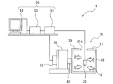
- FIG. 1 is a schematic configuration diagram of a volume measurement device according to a first embodiment of the present invention.
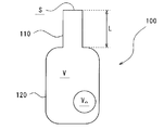
- FIG. 1 is a schematic diagram of a general Helmholtz resonator.
- FIG. 2 is a cross-sectional view of the Helmholtz resonator according to the first embodiment.
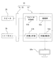
- the control block diagram. 4 is a graph showing a relationship between a resonance frequency and an amplitude. 9 is a graph showing the relationship between the volume of a fish and the resonance frequency. 4 is a graph showing the measurement accuracy for fish volume.
- 5 is a graph showing the relationship between the resonance frequency and the amplitude for each size of the opening. 5 is a graph showing the relationship between the volume of a bubble and the resonance frequency for each size of an opening.
- a volume measuring device 1 of the present embodiment measures the volume of aquatic organisms such as fish using sound resonance, using Helmholtz resonance theory as a measurement principle.
- a fish will be described as an example of an object to be measured, but the volume measuring device 1 can measure the volume of an arbitrary object.
- water or seawater will be described as an example of the liquid to be used, but the volume measuring device 1 can use any liquid.
- the volume measuring device 1 includes a first container 20, a second container 30, a neck 40, and a control device 50.
- the first container 20, the second container 30, and the neck 40 form the Helmholtz resonator 10.
- a typical Helmholtz resonator 100 comprises a single neck 110 and a single container 120, filled with air.
- the neck portion 110 has a cylindrical shape
- the container portion 120 has a bottomed cylindrical shape communicating with the neck portion 110.
- the general Helmholtz resonator 100 is generally shaped like a beer bottle.
- sound vibration is generated at the neck 110 due to the spring-like nature of the air in the container 120. It is known that this vibration is Helmholtz resonance and has a unique resonance frequency according to the shape of the Helmholtz resonator 100.
- the length L and the cross-sectional area S of the neck portion 110 are set to be the volume V of the container portion 120.
- Resonance frequency f at the time of putting the object volume V o to the container portion 120 is represented by the following formula (1).
- L s is the open end correction amount.
- the Helmholtz resonator 10 having a shape in which two necks 110 of the Helmholtz resonator 100 of FIG. 2 are shared and connected is used (see FIG. 3).
- the fish F and the sound generation source (a speaker 25 described later) can be separated, and a decrease in measurement accuracy can be prevented.
- a device that can be used in water as a measuring device, it is possible to prevent a decrease in measurement accuracy even when the fish F is used as an object.
- the first container 20 defines a first space S1 inside.
- the first container 20 has, for example, a cylindrical shape with a bottom and is made of stainless steel. However, the shape and material of the first container 20 are not particularly limited.
- a speaker (sound generator) 25 is arranged in the first space S1. Specifically, one end of the first container 20 is configured by the speaker 25.
- the speaker 25 is for underwater use, and can generate a sound having a frequency of about 100 to 10000 Hz, for example.
- the speaker 25 is electrically connected to the control device 50 by wire, and the control device 50 can control the sound generation frequency.
- the second container 30 defines a second space S2 inside.
- the second container 30 has, for example, a rectangular parallelepiped box shape and is made of an acrylic resin.
- the shape and material of the second container 30 are not particularly limited, and may be, for example, a bottomed cylindrical shape.
- a circular opening 31a in a plan view through which the fish F and the like can be put in and out is provided at the center of the upper wall 31 of the second container 30.
- the upper wall 31 is fixed to the side wall 32 of the second container 30 without any gap, so that sound does not leak from the fixed part.
- the second container 30 contains a fish F to be measured and a hydrophone (sound collecting unit) 35.
- the hydrophone 35 is an underwater microphone, and can collect sound having a frequency of about 20 to 20,000 Hz, for example.
- the hydrophone 35 is of a wired type, and is electrically connected to the control device 50 (see FIG. 1) through an electric wire extending through the opening 31a.
- the hydrophone 35 is arrange
- the speaker 25 and the hydrophone 35 may be those for underwater use, and commercially available ones can be used. In this embodiment, both of the wired type are used, but a wireless type may be used.
- the neck portion 40 defines a flow path FP that communicates the first space S1 and the second space S2.
- the neck 40 is, for example, cylindrical.
- the cross-sectional area perpendicular to the longitudinal central axis CL of the neck portion 40 is smaller than the same cross-sectional area of the first container 20 and smaller than the same cross-sectional area of the second container 30. That is, the Helmholtz resonator 10 has a shape narrowed by the neck portion 40.
- the shape of the neck portion 40 is not particularly limited, it is preferable that the length of the neck portion 40 is short, and that the cross-sectional area is large. Under these preferable conditions, the resonance frequency can be increased and the measurement accuracy can be improved, as can be seen with reference to Expression (2) described later.
- a net (passage prevention member) 41 for preventing the fish F from passing through the flow path FP of the neck portion 40 is provided at an end of the neck portion 40 on the second container 30 side.
- the size of the mesh of the net 41 is set so that the fish F can pass through without passing through the fish F without any influence.
- a wire mesh may be used instead of the net 40 as the passage preventing member.
- a screw mechanism 42 is provided at the end of the neck portion 40 on the first container 20 side.
- the first container 20 is configured to be detachable from the neck 40 by the screw mechanism 42.
- the first container 20 can be removed from the neck portion 40 and carried.
- the second container 30 may be configured to be removable with respect to the neck portion 40, or both the first container 20 and the second container 30 may be configured to be removable with respect to the neck portion 40. May be. Further, the first container 20 and the second container 30 may be fixed to the neck 40 so as not to be detachable.
- the first container 20, the second container 30, and the neck 40 are arranged so as to share the same central axis CL.
- control device 50 includes an amplifier 51, a sound device 52, and a computer 53.
- the amplifier 51 amplifies the analog electric signal from the hydrophone 35 and converts it into a digital electric signal, which is transmitted to the sound device 52.
- the amplifier 51 amplifies an electric signal from the sound device 52 and transmits the amplified electric signal to the speaker 25.
- the sound device 52 receives an electric signal from the amplifier 51 and performs various processes necessary for computer processing. Further, it receives an electric signal from the computer 53 and performs various processes necessary for controlling the speaker 25.
- the computer 53 receives an input signal from the sound device 52, performs various controls, and sends an output signal to the sound device 52.
- the amplifier 51 and the sound device 52 may be incorporated in the computer 53.
- the configuration of the control device 50 is not particularly limited as long as the subsequent control can be substantially executed.
- computer 53 includes a speaker control unit 53a, a resonance analysis unit 53b, a storage unit 53c, a volume calculation unit 53d, and a monitor 53e.
- speaker control unit 53a a speaker control unit 53a
- resonance analysis unit 53b a resonance analysis unit 53b
- storage unit 53c a storage unit 53c
- volume calculation unit 53d a volume calculation unit 53d
- monitor 53e a monitor 53e.
- amplifier 51 and the sound device 52 are shown as one block for simplicity.
- the speaker control unit 53a controls the speaker 25.
- the frequency of the sound emitted from the speaker 25 is changed from a low frequency to a high frequency (or in the opposite direction) within a predetermined frequency range.
- the predetermined frequency range is set according to the size and shape of the Helmholtz resonator 10.
- the resonance analysis unit 53b performs a frequency analysis for obtaining a resonance frequency (a target resonance frequency f) based on a signal obtained from the speaker 25.
- the frequency analysis method may be based on, for example, Fourier analysis.
- the resonance analysis unit 53b acquires the target resonance frequency f, which is the frequency of the resonance sound generated in the second space S2 by the sound emitted from the speaker 25 when the fish F is present in the second space S2.
- the target resonance frequency f is expressed by the following equation (2) based on Helmholtz resonance theory.
- the constants K1 and K2 represent the bulk modulus in the first space S1 and the bulk modulus in the second space S2, respectively.
- Bulk modulus K1, K2 is a value calculated based on the bulk modulus K o of the bulk modulus K w and fish F water.
- the constant S represents the cross-sectional area of the neck portion 40
- the constant L represents the length of the neck portion 40
- the constant Ls represents the opening end correction amount.
- Storage unit 53c stores a reference resonance frequency f 0 is the frequency of the resonance sound generated in the second space S2 by the sound emitted by the loudspeaker 25 when the in the second space S2 without the fish F is present.
- Reference resonance frequency f 0 can be obtained in advance by experiments.
- the reference resonance frequency f 0 is expressed by the following equation (3) based on Helmholtz resonance theory.
- Equation (2) when deriving the volume V o on the basis of (3), of the formula (4) below is obtained.
- the volume calculating unit 53d calculates the volume V 0 which fish F by the above equation (4).
- the sum of the volume V o of all the fish F in the second chamber 30 is calculated.
- the volume V o of measured fish F is displayed on the monitor 53e.
- equation (4) values other than the target resonance frequency f can be obtained in advance. Therefore, the only variable in equation (4) is the target resonance frequency f.
- the volume W 1 was set to 0.471 L
- the volume W 2 of the water in the second container 30 was set to 4.913 L.
- the opening end correction amount L s is calculated by integrating a predetermined constant 0.6 to the radius 15mm of the neck portion 40.
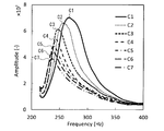
- FIG. 5 is a graph showing the relationship between the resonance frequency (Frequency [Hz]) and the amplitude (Amplitude) obtained under the above experimental conditions.
- the horizontal axis of the graph indicates the frequency of the sound, and the vertical axis indicates the amplitude of the sound.
- the graph seven curves C1 ⁇ C7 are drawn for each fish volume V o. Specifically, the volume V o of the fish F, 0mL (C1), 56.159mL (C2), 95.88mL (C3), 119.622mL (C4), 133.459mL (C5), 145.769mL ( C6) and 171.36 mL (C7) are shown.
- the curves C1 to C7 resonance occurs at the peak frequency.
- each peak frequency of the curves C1 to C7 is each resonance frequency. Looking at the graph, the larger the volume V 0, it can be seen that the resonant frequency and amplitude is reduced.
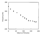
- FIG. 6 is a graph showing the relationship between the volume of fish (Volume of fish [mL]) and the resonance frequency (Frequency [Hz]).
- the horizontal axis of the graph represents the volume V o of the fish, the vertical axis represents the resonance frequency. Looking at the graph, it is higher resonant frequency fish volume V o increases decreased.
- the volume V o and the resonance frequency of the fish F reveals that there is a correlation.
- the volume V o of functionally fish F by the above formula (4) may be obtained the volume V o of the fish F by an operation table that alternatively previously prepared.
- Computation table is for a particular combination of target resonance frequency f and the reference resonance frequency f 0 respectively, stores a volume V o of the fish F.
- Calculation table by experiment, may be created conducted experiments the volume V o of the fish as an output value and a target resonance frequency f and the reference resonance frequency f 0 as the input value.
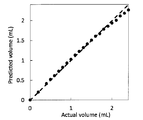
- FIG. 7 shows the measurement accuracy of the volume measurement device 1 of the present embodiment.
- the horizontal axis indicates the actual volume of fish F (Actual @ volume [mL])
- the vertical axis indicates the volume of fish (Predicted @ volume [mL]) measured (estimated) by the volume measuring device 1. I have.
- the graph shows that high-precision measurement has been achieved.
- volume measurement device 1 of the present embodiment there are the following advantages.
- the first container 20, the second container 30, and the neck 40 constitute the Helmholtz resonator 10. Based on the resonance frequency of the Helmholtz resonator 10, the volume of the target aquatic organism (the fish F in the present embodiment) is calculated, so that the volume of the fish F existing in the water can be measured without contact. In particular, measurement is possible even when the water is dirty so that the fish F cannot be seen. In addition, since the sound generation configuration does not use the water flow as in the related art, the volume can be safely measured without damaging the fish F. Further, since the Helmholtz resonator 10 has two containers (the first container 20 and the second container 30), the roles are divided into the first container 20 for generating sound and the second container 30 for measurement. be able to.
- the volume measurement device 1 of the present embodiment is suitable for grasping the growth status of the fish F and the like active in water as described as an example.
- the number of fish in an aquarium can be ascertained, and the same kind of fish is cultivated, so that the growth status is almost the same. In other words, fish of significantly different sizes are rarely farmed in the same aquarium. Therefore, by using the second container 30 as a large water tank, the total volume of all the fish F is grasped by the volume measuring device 1 and divided by the number of fish, whereby the volume per cultured fish can be grasped.
- the opening 31a is provided in the upper wall 31 of the second container 30, the inside of the second container 30 can be accessed from the opening 31a. Therefore, the fish F can be taken in and out, and maintenance inside the second container 30 is possible.
- a wired hydrophone 35 can be disposed in the second container 30 through the opening 31a.
- the opening 31a is not provided from the viewpoint of generating resonance in the second container 30. In this regard, the feasibility of the measurement according to the size of the opening 31a will be described later.
- the fish F is prevented from entering the first space S1 through the neck portion 40 by the net 41 arranged in the neck portion 40. If the fish F enters the first space S1, the sound from the speaker 25 will be attenuated, and accurate measurement may not be possible. Therefore, this is prevented, and stable and accurate measurement is enabled.
- the first container 20 is detachable from the neck portion 40, convenience is improved. Even if the second container 30 is a large water tank as described above, the first container 20 can be removed and carried. That is, the volume measuring device 1 can be used as a portable type.
- the resonance frequency of the Helmholtz resonator 10 can be stably and accurately determined. Can be measured. Since the sound has the property of spreading evenly, the sound emitted from the speaker 25 in the first space S1 spreads evenly in the second space S2 through the neck portion 40. When the first container 20, the second container 30, and the neck portion 40 have the same central axis CL, sound resonance can be equalized.
- FIGS. 8 to 10 show the results of studying the feasibility of measurement depending on the size of the opening 31a.
- the experimental conditions are the same as those described in the present embodiment except for the size of the opening 31a.
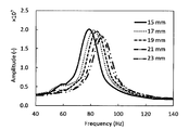
- FIG. 8 is a graph showing the relationship between the resonance frequency (Frequency [Hz]) and the amplitude (Amplitude).
- the horizontal axis of the graph indicates the frequency of the sound, and the vertical axis indicates the amplitude of the sound.
- five curves are drawn for each diameter of the opening 31a (see FIG. 3). Specifically, the results when the diameter of the opening 31a is 15 mm, 17 mm, 19 mm, 21 mm, and 23 mm are shown.
- resonance occurs at the peak frequency. In other words, each peak frequency of the five curves is each resonance frequency.
- the graph shows that as the diameter of the opening 31a increases, the resonance frequency increases while the amplitude decreases.
- FIG. 9 is a graph showing the relationship between the volume of a bubble (air) (Volume of air [mL]) and the resonance frequency (Frequency [Hz]), which is regarded as an object.
- the horizontal axis of the graph indicates the volume of the bubble, and the vertical axis indicates the resonance frequency.
- a result of a test in which a bubble assumed as an object is formed in the second space S2 and the volume of the bubble is measured is shown.
- the bubbles are formed as indicated by reference numeral Ar in FIG. 11 shown in a third embodiment described later.
- five types of data are drawn for each diameter of the opening 31a (see FIG. 3).
- the results when the diameter of the opening 31a is 15 mm, 17 mm, 19 mm, 21 mm, and 23 mm as in FIG. 8 are shown.
- the graph shows that the resonance frequency increases as the diameter of the opening 31a increases.
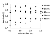
- FIG. 10 is a graph showing the relationship between the volume (Volume @ of @ air [mL]) and the amplitude (Amplitude) of a bubble (air) assumed as an object.
- the horizontal axis of the graph indicates the volume of the bubble, and the vertical axis indicates the amplitude of the sound.
- FIG. 9 a result of performing a test in which a bubble assumed as an object is formed in the second space S2 and the volume of the bubble is measured is shown.
- five types of data are drawn for each diameter of the opening 31a (see FIG. 3). 8 and 9 show the results when the diameter of the opening 31a is set to 15 mm, 17 mm, 19 mm, 21 mm, and 23 mm as in FIGS.
- the graph shows that the amplitude decreases as the diameter of the opening 31a increases.
- the resonance frequency and the amplitude can be measured even when the diameter of the opening 31a is variously changed, and there is a certain correlation between these and the bubbles (corresponding to the target fish). Understand. Therefore, it can be confirmed that measurement can be realized even when the size of the opening 31a is variously changed.
- the volume measuring device 1 of the present embodiment differs from the first embodiment in the analysis method in the resonance analyzer 53b.
- the rest is substantially the same as the first embodiment. Therefore, description of the same parts as those in the first embodiment may be omitted.
- the volume calculation unit 53d of the present embodiment calculates the volume V o of the fish F taking into account the elasticity of the first container 20 and second container 30 of the walls.
- the first container 20 and the second container 30 expand somewhat when filled with water. Since the resonance frequency is affected by the expansion, the volume of the fish F can be measured with higher accuracy by performing the correction in consideration of the expansion.
- the correction is effective because the second container 30 is made of a relatively soft material such as an acrylic resin.
- a reference resonance frequency f 0 is expressed by the following equation on the basis of Helmholtz resonance theory (5).
- E r1 Resonator coefficient of the first container
- E r2 Resonator coefficient of the second container
- resonator coefficients E r2 resonators coefficient E r1 and the second container of the first container, Sadamari depending on material of the container, which is a value indicating the degree of expansion of the container.
- the resonator coefficients Er1 and Er2 can be obtained experimentally in advance as constants.
- the target resonance frequency f is expressed by the following equation (6) based on Helmholtz resonance theory.
- Equation (5) when deriving the volume V o on the basis of (6), the formula (7) below is obtained.
- the volume calculation unit 53d of the present embodiment estimates measure the volume V o of the fish F by the equation (7).
- this embodiment it can be measured in consideration of the elasticity of the first container 20 and second container 30 of the walls of the volume V o of the fish F with high accuracy.
- This embodiment is particularly effective when the first container 20 and the second container 30 are made of a relatively soft material such as a resin, because they expand significantly.
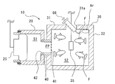
- the volume measuring device 1 of the present embodiment shown in FIG. 11 includes a bubble injector 60 for injecting air into the second container 30.
- the rest is substantially the same as the first embodiment. Therefore, description of the same parts as those in the first embodiment may be omitted.
- the bubble injector 60 is, for example, a syringe type, and is disposed in the opening 31 a of the second container 30.
- the bubble (air) Ar injected from the bubble injector 60 accumulates in the upper corner of the second space S2.
- the bubble injector 60 is graduated to indicate the amount of air injected.
- FIG. 12 shows the measurement accuracy of the volume measurement device 1 of the present embodiment.
- the horizontal axis indicates the actual air volume (Actual @ volume [mL])
- the vertical axis indicates the air volume (Predicted @ volume [mL]) measured (estimated) by the volume measurement device. .
- the graph shows that high-precision measurement has been achieved.
- the bubbles can be formed in the second space S2 as the target object by the bubble injector 60. Therefore, a test of measurement accuracy can be easily performed.
- volume measurement device 1 of the present embodiment can grasp the growth status.
- the first container 20 and the neck 40 are arranged in the second container 30.
- the rest is substantially the same as the first embodiment. Therefore, description of the same parts as those in the first embodiment may be omitted.
- one end of the neck portion 40 is attached to the first container 20, and the other end is attached to the net 41 and is open.
- the first container 20 and the neck portion 40 are arranged in the second container 30 as described above, that is, are arranged in the second space S2.
- the first container 20 and the neck portion 40 can be configured without connecting to the second container 30. Therefore, as long as the second container 30 can accommodate the first container 20 and the neck portion 40, the first container 20 and the neck portion 40 can be configured without depending on the size and shape of the second container 30.
- the volume measuring device 1 of the present embodiment may be used by sinking the first container 20 and the neck portion 40 into the water tank.
Landscapes
- Life Sciences & Earth Sciences (AREA)
- Zoology (AREA)
- Environmental Sciences (AREA)
- Physics & Mathematics (AREA)
- Fluid Mechanics (AREA)
- General Physics & Mathematics (AREA)
- Marine Sciences & Fisheries (AREA)
- Animal Husbandry (AREA)
- Biodiversity & Conservation Biology (AREA)
- Farming Of Fish And Shellfish (AREA)
Abstract
体積計測装置1は、第1空間S1を画定する第1容器20と、第2空間S2を画定する第2容器30と、空間S1,S2を流体的に連通する流路FPを画定するネック部40と、第1空間S1に配置され、所定の周波数範囲の音を発するスピーカ25と、第2空間S2に配置されたハイドロホン35と、第2空間S2に魚Fが存在しない場合におけるスピーカ25の発する音によって第2空間S2に生じる共鳴音の周波数である基準共鳴周波数f0を記憶した記憶部53cと、ハイドロホン35で集音された音を分析することで、第2空間S2に魚Fが存在する場合における同共鳴音の周波数である対象共鳴周波数fを取得する共鳴分析部53bと、周波数f0,fに基づいて魚Fの体積Voを算出する体積演算部53dとを備える。
Description
本発明は、体積計測装置および体積計測方法に関する。
特許文献1には、ネック部と容器本体を備えるヘルムホルツ共鳴器を用いて水中で活動する生魚等の体積を計測する方法が開示されている。このヘルムホルツ共鳴器には、ネック部の開口部にリード部が設けられている。リード部に所定流速の水流を所定方向から当てると音が発生し、共鳴する。当該方法は、リード部から発生する音の共鳴周波数に基づいて生魚等の体積を計測するものである。
しかし、リード部から発生する音を共鳴させるためには、リード部に当てる水流の流速を速くすることが必要な場合があり、当該水流によって生魚が傷つけられるおそれがある。従って、特許文献1の方法は、養殖魚等の体積を計測するためには適さない場合がある。また、計測精度の観点からも改善の余地がある。
本発明は、液体中に存在する対象物の体積を高精度かつ安全に計測できる体積計測装置および体積計測方法を提供することを課題とする。
本発明の第1の態様は、液体を貯留する第1空間を画定する第1容器と、前記液体を貯留して対象物が液体内に配置される第2空間を画定する第2容器と、前記第1空間と前記第2空間とを流体的に連通する流路を画定するネック部と、前記第1空間に配置され、所定の周波数範囲の音を発する発音部と、前記第2空間に配置された集音部と、前記発音部から発せられ、前記第2空間にて共鳴し、前記集音部にて集音された音の共鳴周波数を用いて前記対象物の体積を算出する制御装置とを備える、体積計測装置を提供する。
前記制御装置は、前記第2空間に前記対象物が存在しない場合における前記発音部の発する音によって前記第2空間に生じる共鳴音の周波数である基準共鳴周波数を記憶した記憶部と、前記集音部で集音された音から、前記第2空間に前記対象物が存在する場合における前記発音部の発する音によって前記第2空間に生じる前記共鳴音の周波数である対象共鳴周波数を取得する共鳴分析部と、前記基準共鳴周波数および前記対象共鳴周波数に基づいて前記対象物の体積を算出する体積演算部とを備えてもよい。
これらの構成によれば、第1容器と第2容器とネック部とによってヘルムホルツ共鳴器が構成される。このヘルムホルツ共鳴器の共鳴周波数に基づいて対象物の体積を算出するため、液体中に存在する対象物の体積を非接触で計測できる。特に、対象物を目視できない程に液体が汚れている場合でも計測可能である。また、従来のように水流を利用した発音構成ではないため、対象物を傷つけることなく安全に体積を計測できる。また、ヘルムホルツ共鳴器が2つの容器(第1容器と第2容器)を有しているため、音を発生させる第1容器と計測のための第2容器とに役割を分けることができる。これにより、音の発生と計測をそれぞれ安定して高精度に実行できる。また、1つの容器からなるヘルムホルツ共鳴器に比べて高周波数の共鳴周波数を得ることもできる。共鳴周波数が高周波数となると、基準共鳴周波数と、対象共鳴周波数との差を大きくすることができる。従って、高精度での計測が可能となる。特に、本装置は、水中で活動する養殖魚等の生育状況を把握することに適している。その場合、第2容器を大きな水槽と解し、対象物を養殖魚と解することができる。
前記体積演算部は、演算テーブルを有し、前記演算テーブルは、それぞれ前記対象共鳴周波数と前記基準共鳴周波数の特定の組み合わせに対するものである、前記対象物の体積を格納していてもよい。
この構成によれば、都度複雑な計算を要することなく、予め設定した演算テーブルを用いて迅速に対象物の体積を計測できる。
前記体積演算部は、以下の式に基づいて前記対象物の体積V0を算出してもよい。

V0:対象物の体積
Ko:対象物の体積弾性率
Kw:液体の体積弾性率
f0:基準共鳴周波数
f:対象共鳴周波数
W1:第1容器に貯留された液体の体積
W2:第2容器に貯留された液体の体積
この構成によれば、対象物の体積を具体的に高精度に計測できる。上記式において、対象共鳴周波数以外の値は予め求めることができるため、上記式の変数は対象共鳴周波数のみである。ここで、液体の体積弾性率Kwは、液体の密度ρwに当該液体中での音速Cwの2乗を積算して求められる値である(Kw=ρw×Cw
2)。同様に、対象物の体積弾性率Koは、対象物の密度ρoに当該対象物中での音速Coの2乗を積算して求められる値である(Ko=ρo×Co
2)。
前記体積演算部は、以下の式に基づいて前記対象物の体積V0を算出してもよい。

V0:対象物の体積
Ko:対象物の体積弾性率
Kw:液体の体積弾性率
f0:基準共鳴周波数
f:対象共鳴周波数
W1:第1容器に貯留された液体の体積
W2:第2容器に貯留された液体の体積
Er1:第1容器の共鳴器係数
Er2:第2容器の共鳴器係数
この構成によれば、第1容器および第2容器の壁の弾性を考慮して対象物の体積を高精度に計測できる。第1容器および第2容器は実際上完全な剛体ではないため、液体で満たされることによって幾分膨張する。共鳴周波数はこの膨張の影響を受けるため、膨張を考慮した補正を行うことで、対象物の体積を一層高精度に計測できる。特に容器が樹脂などの比較的軟性材料からなる場合には容器が大きく膨張するため、上記補正は有効である。ここで、第1容器の共鳴器係数Er1および第2容器の共鳴器係数Er2は、容器の材質等に応じて定まり、容器の膨張の程度を示す値であり、予め実験的に求めることができる。
前記第2容器は前記液体表面より上部の壁の一部に開口部が設けられてもよい。
この構成によれば、開口部から第2容器内にアクセスできる。従って、対象物の出し入れや第2容器内のメンテナンスが可能となる。また、有線式の集音部を、開口部を通じて第2容器内に配置することもできる。
前記対象物が前記ネック部の前記流路を通過することを防止するための通過防止部材をさらに備えてもよい。
この構成によれば、ネットなどの通過防止部材によって、対象物がネック部を通って第1空間に進入することを防止できる。仮に、対象物が第1空間に進入すると、発音部からの音が減衰し、正確な測定ができないおそれがある。従って、これを防止し、安定した高精度の計測を可能としている。
前記第1容器および前記第2容器の少なくとも一方は、前記ネック部に対して取り外し可能に取り付けられていてもよい。
この構成によれば、ヘルムホルツ共鳴器の一部が取り外し可能であることによって、利便性を向上できる。仮に、第2容器が大きな水槽である場合であっても、第1容器(およびネック部)を取り外して持ち運ぶこともできる。即ち、ポータブル型として体積計測装置を使用することもできる。
前記ネック部は、前記第1容器に取り付けられ、前記第1容器および前記ネック部は、前記第2空間に配置されてもよい。
この構成により、第2容器に接続することなく第1容器およびネック部を構成できる。従って、第2容器が第1容器およびネック部を収容できる限り、第2容器の大きさや形状に依存することなく第1容器およびネック部を構成できる。上記構成は、例えば、第2容器が大きな水槽である場合などに第1容器およびネック部を当該水槽に沈めて使用することが考えられる。
前記第2空間に空気を注入するバブル注入部をさらに備えてもよい。
この構成によれば、バブル注入部によって対象物に見立てた気泡(バブル)を第2空間に形成できる。従って、計測精度の試験を簡易に行うことができる。
前記第1容器と、前記第2容器と、前記ネック部とは、同一の中心軸を共有するように配置構成されてもよい。
この構成によれば、ヘルムホルツ共鳴器の共鳴周波数を安定して高精度に計測できる。音は均等に広がる性質を有するため、第1空間の発音部から発せられた音は、ネック部を通って第2空間内で均等に広がる。第1容器と第2容器とネック部とが同一中心軸を有すると、音の共鳴を均等にできる。
本発明の第2の態様は、液体を貯留する第1空間を画定する第1容器と、前記液体を貯留して対象物が配置される第2空間を画定する第2容器と、前記液体が充填されて前記第1空間と前記第2空間とを流体的に連通する流路を画定するネック部と、前記第1空間に配置され、所定の周波数範囲の音を発する発音部と、前記第2空間に配置された集音部とを準備し、前記第2空間に前記対象物が存在しない場合における前記発音部の発する音によって前記第2空間に生じる共鳴音の周波数である基準共鳴周波数を前記集音部を使用して測定し、前記第2空間に前記対象物が存在する場合における前記発音部の発する音によって前記第2空間に生じる共鳴音の周波数である対象共鳴周波数を前記集音部を使用して測定し、前記基準共鳴周波数および前記対象共鳴周波数に基づいて前記対象物の体積を算出する、体積計測方法を提供する。
この方法によれば、前述のようにして液体中に存在する対象物の体積を高精度かつ安全に計測できる。
本発明によれば、体積計測装置および体積計測方法において、第1容器および第2容器を有するヘルムホルツ共鳴器を利用しているため、液体中に存在する対象物の体積を高精度かつ安全に計測できる。
以下、添付図面を参照して本発明の実施形態を説明する。
(第1実施形態)
図1を参照して、本実施形態の体積計測装置1は、ヘルムホルツ共鳴理論を計測原理として用い、音の共鳴を利用して魚等の水圏生物の体積を計測するものである。以下の実施形態では、測定する対象物として魚を例に説明するが、体積計測装置1は任意の対象物の体積を計測できる。同様に、使用する液体として水ないし海水を例に説明するが、体積計測装置1は任意の液体を使用できる。
図1を参照して、本実施形態の体積計測装置1は、ヘルムホルツ共鳴理論を計測原理として用い、音の共鳴を利用して魚等の水圏生物の体積を計測するものである。以下の実施形態では、測定する対象物として魚を例に説明するが、体積計測装置1は任意の対象物の体積を計測できる。同様に、使用する液体として水ないし海水を例に説明するが、体積計測装置1は任意の液体を使用できる。
体積計測装置1は、第1容器20と、第2容器30と、ネック部40と、制御装置50とを備える。第1容器20と、第2容器30と、ネック部40とによって、ヘルムホルツ共鳴器10が構成される。
図2を参照して、本実施形態とは異なるが、一般的なヘルムホルツ共鳴器100について説明する。一般的なヘルムホルツ共鳴器100は、空気で満たされた、単一のネック部110と、単一の容器部120とで構成される。ネック部110は筒状であり、容器部120はネック部110に連通した有底筒状である。換言すると、一般的なヘルムホルツ共鳴器100は、概ねビール瓶のような形状をしている。このようなヘルムホルツ共鳴器100の内部にて音が発生すると、容器部120内の空気のばね的な性質により、ネック部110で音の振動が発生する。この振動がヘルムホルツ共鳴であり、ヘルムホルツ共鳴器100の形状に応じた固有の共鳴周波数を持つことが知られている。
図2のヘルムホルツ共鳴器100において、ネック部110の長さLおよび断面積Sとし、容器部120の体積Vとする。容器部120内に体積Voの対象物を入れた際の共鳴周波数fは以下の式(1)で表される。ただし、Lsは開口端補正量である。

上記式(1)を体積V0について解き、実際に測定した共鳴周波数fを代入することにより、対象物の体積Voを算出できる。しかし、当該方法では、対象物が音源の近傍にあるときに音を大きく減衰させるおそれがあるため、測定精度の観点で改善の余地がある。また、水中での共鳴周波数fの計測は一般に困難であるため、生魚等の水圏生物を対象物とした場合には適用し難い。
本実施形態では、図2のヘルムホルツ共鳴器100のネック部110を共有して2つ繋げた形状を有するヘルムホルツ共鳴器10を使用する(図3参照)。これにより、魚Fと音の発生源(後述するスピーカ25)を分けることができ、測定精度の低下を防止できる。また、計測機器として水中でも使用可能な機器を使用することで魚Fを対象物とした場合でも測定精度が低下することを防止している。
図3を参照して、本実施形態のヘルムホルツ共鳴器10の構成について説明する。
第1容器20は、内部に第1空間S1を画定している。第1容器20は、例えば、有底円筒状であり、ステンレス製である。ただし、第1容器20の形状や材質は、特に限定されない。第1空間S1には、スピーカ(発音部)25が配置されている。詳細には、第1容器20の一端部がスピーカ25によって構成されている。
スピーカ25は、水中用のものであり、例えば100~10000Hz程度の周波数の音を発生させることができる。スピーカ25は、制御装置50に有線で電気的に接続されており、制御装置50によって音の発生周波数を制御できる。
第2容器30は、内部に第2空間S2を画定している。第2容器30は、例えば、直方体の箱状であり、アクリル樹脂製である。ただし、第2容器30の形状や材質は、特に限定されず、例えば有底円筒状であってもよい。本実施形態では、第2容器30の上壁31の中央部に、魚Fなどを出し入れできる平面視円形の開口部31aが設けられている。また、上壁31は第2容器30の側壁32に隙間なく固着されており、固着された部分からは音が漏出することがないようにされている。
第2容器30には、計測対象となる魚Fと、ハイドロホン(集音部)35とが収容されている。ハイドロホン35は、水中用マイクであり、例えば20~20000Hz程度の周波数の音を集音できる。ハイドロホン35は、有線式であり、開口部31aを通じて延びる電気線を通じて制御装置50(図1参照)と電気的に接続されている。なお、ハイドロホン35は、第2容器30内の任意の位置に配置され、第2空間S2にて共鳴する音を集音できる。
スピーカ25およびハイドロホン35は、水中用のものであればよく、市販のものを使用できる。本実施形態では、ともに有線型のものを使用しているが、無線型のものを使用してもよい。
ネック部40は、第1空間S1と第2空間S2とを連通する流路FPを画定している。ネック部40は、例えば円筒状である。ネック部40の長手方向の中心軸CLに垂直な断面積は、第1容器20の同断面積よりも小さく、かつ、第2容器30の同断面積よりも小さい。即ち、ヘルムホルツ共鳴器10は、ネック部40にて窄められた形状をしている。ネック部40の形状は特に限定されないが、ネック部40の長さは短い方が好ましく、上記断面積は大きい方が好ましい。これらの好ましい条件下では、後述する式(2)を参照してわかるように、共鳴周波数を大きくすることができ、計測精度を向上させることができる。
ネック部40の第2容器30側の端部には、魚Fがネック部40の流路FPを通過することを防止するためのネット(通過防止部材)41が設けられている。ネット41の網目の大きさは、魚Fを通過させることなく、かつ、音が影響なく通過できるように設定されている。また、例えば、通過防止部材として、ネット40に代えて金網を使用してもよい。
本実施形態では、ネック部40の第1容器20側の端部には、ねじ機構42が設けられている。ねじ機構42によって第1容器20がネック部40に対して取り外し可能に構成されている。これにより、第1容器20をネック部40から取り外して持ち運び可能となっている。代替的には、第2容器30がネック部40に対して取り外し可能に構成されていてもよいし、第1容器20および第2容器30の両方がネック部40に対して取り外し可能に構成されていてもよい。また、第1容器20および第2容器30は、ネック部40に対して取り外しできないように固着されていてもよい。
本実施形態では、第1容器20と、第2容器30と、ネック部40とは、同一の中心軸CLを共有するように配置されている。
図1を再び参照して、制御装置50は、アンプ51と、サウンドデバイス52と、コンピュータ53とを備える。
アンプ51は、ハイドロホン35からのアナログの電気信号を増幅するとともにデジタルの電気信号に変換してサウンドデバイス52に伝送している。また、アンプ51は、サウンドデバイス52からの電気信号を増幅してスピーカ25に伝送している。
サウンドデバイス52は、アンプ51からの電気信号を受け、コンピュータ処理に必要な種々の処理を行うものである。また、コンピュータ53からの電気信号を受け、スピーカ25の制御に必要な種々の処理を行うものである。
コンピュータ53は、サウンドデバイス52からの入力信号を受け、種々の制御を行い、サウンドデバイス52に出力信号を送る。なお、アンプ51やサウンドデバイス52はコンピュータ53に組み込まれてもよい。制御装置50の構成は、以降の制御を実質的に実行できるものであれば特に限定されない。
図4を参照して、コンピュータ53は、スピーカ制御部53aと、共鳴分析部53bと、記憶部53cと、体積演算部53dと、モニタ53eとを備える。なお、図示を簡略化するため、図4では、アンプ51とサウンドデバイス52は、1つのブロックで示されている。
スピーカ制御部53aは、スピーカ25を制御する部分である。当該制御では、ヘルムホルツ共鳴器10の共鳴周波数を探るために、所定の周波数範囲で低い周波数から高い周波数に(またはその逆の方向に)、スピーカ25の発する音の周波数を変化させる。所定の周波数範囲は、ヘルムホルツ共鳴器10の大きさや形状などに応じて設定される。
共鳴分析部53bは、スピーカ25から得られた信号に基づいて、共鳴周波数(対象共鳴周波数f)を求めるための周波数分析を行う。周波数分析の方法は、例えばフーリエ解析によるものであってもよい。具体的には、共鳴分析部53bは、第2空間S2に魚Fが存在する場合におけるスピーカ25の発する音によって第2空間S2に生じる共鳴音の周波数である対象共鳴周波数fを取得する。
対象共鳴周波数fは、ヘルムホルツ共鳴理論に基づいて以下の式(2)で表される。ここで、定数K1,K2は、第1空間S1における体積弾性率,第2空間S2における体積弾性率をそれぞれ表している。体積弾性率K1,K2は、水の体積弾性率Kwおよび魚Fの体積弾性率Koに基づいて算出される値である。ここで、水の体積弾性率Kwは、水の密度ρwに水中での音速Cwの2乗を積算して求められる値である(Kw=ρw×Cw
2)。同様に、魚Fの体積弾性率Koは、魚の密度ρoに魚中での音速Coの2乗を積算して求められる値である(Ko=ρo×Co
2)。また、定数Sはネック部40の断面積、定数Lはネック部40の長さ、定数Lsは開口端補正量を表している。



Ko:魚の体積弾性率
Kw:水の体積弾性率
f0:基準共鳴周波数
f:対象共鳴周波数
W1:第1容器に貯留された水の体積
W2:第2容器に貯留された水の体積
記憶部53cは、第2空間S2に魚Fが存在しない場合におけるスピーカ25の発する音によって第2空間S2に生じる共鳴音の周波数である基準共鳴周波数f0を記憶している。基準共鳴周波数f0は、実験により予め求めることができる。
基準共鳴周波数f0は、ヘルムホルツ共鳴理論に基づいて以下の式(3)で表される。

上記の式(2),(3)に基づいて体積Voを導出すると、以下の式(4)が得られる。

本実施形態では、体積演算部53dは、上記の式(4)によって魚Fの体積V0を算出する。これにより、第2容器30内の全ての魚Fの合計の体積Voが算出される。計測された魚Fの体積Voは、モニタ53eに表示される。なお、式(4)では、対象共鳴周波数f以外の値は予め求めることができる。従って、式(4)の変数は対象共鳴周波数fのみである。
以下では、本実施形態の体積計測装置1を用いて、水中の魚Fの体積を具体的に求めた実験結果について説明する。
実験条件は、ネック部40の長さL=30mm、開口端補正量Ls=9.0mm、ネック部40の直径=30mm(断面積S=706.858mm2)、第1容器20の水の体積W1=0.471L、第2容器30の水の体積W2=4.913Lと設定した。なお、開口端補正量Lsはネック部40の半径15mmに所定の定数0.6を積算して算出した。
図5は、上記実験条件の下で得られた共鳴周波数(Frequency[Hz])と振幅(Amplitude)の関係を示すグラフである。グラフの横軸は音の周波数を示し、縦軸は音の振幅を示している。グラフには、魚の体積Voごとに7つの曲線C1~C7が描かれている。具体的には、魚Fの体積Voを、0mL(C1),56.159mL(C2),95.88mL(C3),119.622mL(C4),133.459mL(C5),145.769mL(C6),171.36mL(C7)としたときの結果が示されている。曲線C1~C7では、ピークをとった周波数にて共鳴が発生している。換言すれば、曲線C1~C7の各ピーク周波数が各共鳴周波数である。グラフを見ると、体積V0が大きくなるほど、共鳴周波数および振幅が低下することがわかる。
図6は、魚の体積(Volume of fish[mL])と共鳴周波数(Frequency[Hz])の関係を示すグラフである。グラフの横軸は魚の体積Voを示し、縦軸は共鳴周波数を示している。グラフを見ると、魚の体積Voが大きくなるほど共鳴周波数が低下することがわかる。
図5,6の結果から、魚Fの体積Voと共鳴周波数には相関があることわかる。従って、共鳴周波数を測定することによって、魚の体積Voを推定可能なことがわかる。本実施形態では上記式(4)によって関数的に魚Fの体積Voを求めているが、代替的には予め用意した演算テーブルによって魚Fの体積Voを求めてもよい。演算テーブルは、それぞれ対象共鳴周波数fと基準共鳴周波数f0の特定の組み合わせに対するものである、魚Fの体積Voを格納している。演算テーブルは、予め実験により、対象共鳴周波数fと基準共鳴周波数f0とを入力値として魚の体積Voを出力値として実験を行い作成すればよい。これにより、都度複雑な計算を要することなく、予め設定した演算テーブルを用いて迅速に魚Fの体積Voを計測できる。
本実施形態の体積計測装置1の計測精度を図7に示す。図7のグラフでは、横軸が実際の魚Fの体積(Actual volume[mL])を示し、縦軸が体積計測装置1によって計測(推定)した魚の体積(Predicted volume[mL])を示している。グラフを見ると、高精度の測定を実現したことがわかる。
本実施形態の体積計測装置1によれば、以下の優位点がある。
第1容器20と第2容器30とネック部40とによってヘルムホルツ共鳴器10が構成される。このヘルムホルツ共鳴器10の共鳴周波数に基づいて対象物となる水圏生物(本実施形態では魚F)の体積を算出するため、水中に存在する魚Fの体積を非接触で計測できる。特に、魚Fを目視できない程に水が汚れている場合でも計測可能である。また、従来のように水流を利用した発音構成ではないため、魚Fを傷つけることなく安全に体積を計測できる。また、ヘルムホルツ共鳴器10が2つの容器(第1容器20と第2容器30)を有しているため、音を発生させる第1容器20と計測のための第2容器30とに役割を分けることができる。これにより、音の発生と計測をそれぞれ安定して高精度に実行できる。また、1つの容器からなるヘルムホルツ共鳴器10(図2参照)に比べて高周波数の共鳴周波数を得ることもできる。共鳴周波数が高周波数となると、基準共鳴周波数f0と、対象共鳴周波数fとの差を大きくすることができる。従って、高精度での計測が可能となる。
特に、本実施形態の体積計測装置1は、一例として説明したように水中で活動する魚F等の生育状況を把握することに適している。一般に養殖業では、水槽内の魚の数を把握できるようになっており、同種の魚が養殖されるために生育状況も概ね等しくなる。換言すれば、著しくサイズの異なる魚が同じ水槽内で養殖されることは稀である。そのため、第2容器30を大きな水槽として、体積計測装置1によって全ての魚Fの合計の体積を把握し、魚の数で除算することで、養殖魚の1匹当たりの体積を把握できる。
また、第2容器30の上壁31に開口部31aを設けているため、開口部31aから第2容器30内にアクセスできるようになっている。従って、魚Fの出し入れや第2容器30内のメンテナンスが可能である。また、図2に示すように有線式のハイドロホン35を、開口部31aを通じて第2容器30内に配置することも可能となる。ただし、開口部31aは、第2容器30内で共鳴を発生させる観点からは設けられない方が好ましい。この点、開口部31aの大きさに伴う計測の実現可能性については後述する。
また、ネック部40に配置されたネット41によって、魚Fがネック部40を通って第1空間S1に進入することが防止されている。仮に、魚Fが第1空間S1に進入すると、スピーカ25からの音が減衰し、正確な測定ができないおそれがある。従って、これを防止し、安定した高精度の計測を可能としている。
また、第1容器20がネック部40に対して取り外し可能であることによって、利便性を向上させている。仮に、第2容器30が前述のように大きな水槽である場合であっても、第1容器20を取り外して持ち運ぶこともできる。即ち、ポータブル型として体積計測装置1を使用することもできる。
また、第1容器20と、第2容器30と、ネック部40とは、同一の中心軸CLを共有するように配置されているため、ヘルムホルツ共鳴器10の共鳴周波数を安定して高精度に計測できる。音は均等に広がる性質を有するため、第1空間S1のスピーカ25から発せられた音は、ネック部40を通って第2空間S2内で均等に広がる。第1容器20と第2容器30とネック部40とが同一中心軸CLを有すると、音の共鳴を均等にできる。
図8~10は、開口部31aの大きさに伴う計測の実現可能性について検討した結果である。実験条件は、開口部31aの大きさに関する以外、本実施形態で説明したものと同じである。
図8は、共鳴周波数(Frequency[Hz])と振幅(Amplitude)の関係を示すグラフである。グラフの横軸は音の周波数を示し、縦軸は音の振幅を示している。グラフには、開口部31a(図3参照)の直径ごとに5つの曲線が描かれている。具体的には、開口部31aの直径を、15mm,17mm,19mm,21mm,23mmとしたときの結果が示されている。5つの曲線では、ピークをとった周波数にて共鳴が発生している。換言すれば、5つの曲線の各ピーク周波数が各共鳴周波数である。グラフを見ると、開口部31aの直径が大きくなるほど、共鳴周波数が増加する一方で振幅が低下することがわかる。
図9は、対象物に見立てたバブル(空気)の体積(Volume of air[mL])と共鳴周波数(Frequency[Hz])の関係を示すグラフである。グラフの横軸はバブルの体積を示し、縦軸は共鳴周波数を示している。ここでは、対象物に見立てたバブルを第2空間S2に形成し、当該バブルの体積を計測する試験を行った結果を示している。例えば、バブルは後述する第3実施形態で示す図11の符号Arで示すように形成されている。グラフには、開口部31a(図3参照)の直径ごとに5種類のデータが描かれている。詳細には、図8と同様に開口部31aの直径を、15mm,17mm,19mm,21mm,23mmとしたときの結果が示されている。グラフを見ると、開口部31aの直径が大きくなるほど共鳴周波数が増大することがわかる。
図10は、対象物に見立てたバブル(空気)の体積(Volume of air[mL])と振幅(Amplitude)の関係を示すグラフである。グラフの横軸はバブルの体積を示し、縦軸は音の振幅を示している。ここでは、図9の場合と同様に対象物に見立てたバブルを第2空間S2に形成し、当該バブルの体積を計測する試験を行った結果を示している。グラフには、開口部31a(図3参照)の直径ごとに5種類のデータが描かれている。詳細には、図8,9と同様に開口部31aの直径を、15mm,17mm,19mm,21mm,23mmとしたときの結果が示されている。グラフを見ると、開口部31aの直径が大きくなるほど振幅が低下することがわかる。
図8~10の結果から、開口部31aの直径を様々に変更した場合でも共鳴周波数や振幅を測定できるとともに、これらとバブル(対象物の魚に対応)の間に一定の相関があることがわかる。従って、開口部31aの大きさを様々に変更した場合でも計測が実現可能であることが確認できる。
(第2実施形態)
本実施形態の体積計測装置1は、共鳴分析部53bでの分析方法が第1実施形態と異なる。これ以外は、第1実施形態と実質的に同じである。従って、第1実施形態と同じ部分については説明を省略する場合がある。
本実施形態の体積計測装置1は、共鳴分析部53bでの分析方法が第1実施形態と異なる。これ以外は、第1実施形態と実質的に同じである。従って、第1実施形態と同じ部分については説明を省略する場合がある。
本実施形態の体積演算部53dは、第1容器20および第2容器30の壁の弾性を考慮して魚Fの体積Voを算出する。第1容器20および第2容器30は、水で満たされることによって幾分膨張する。共鳴周波数はこの膨張の影響を受けるため、膨張を考慮した補正を行うことで、魚Fの体積を一層高精度に計測できる。特に本実施形態では、第2容器30がアクリル樹脂のような比較的軟性材料からなるため、当該補正は有効である。
第2容器30内に魚Fが存在しないとき、基準共鳴周波数f0は、ヘルムホルツ共鳴理論に基づいて以下の式(5)で表される。



Er2:第2容器の共鳴器係数
なお、第1容器の共鳴器係数Er1および第2容器の共鳴器係数Er2は、容器の材質等に応じて定まり、容器の膨張の程度を示す値である。共鳴器係数Er1,Er2は、定数として予め実験的に求めることができる。詳細には、共鳴器係数Er1,Er2は、第1容器20および第2容器30の各共鳴器の体積弾性率Kr1,Kr2を各共鳴器の体積変化Vr1,Vr2で割った値として表される(Er1=Kr1/Vr1、Er2=Kr2/Vr2)。
第2容器30内に魚Fが存在するとき、対象共鳴周波数fは、ヘルムホルツ共鳴理論に基づいて以下の式(6)で表される。



上記の式(5),(6)に基づいて体積Voを導出すると、以下の式(7)が得られる。本実施形態の体積演算部53dは、式(7)によって魚Fの体積Voを推定計測する。

本実施形態によれば、第1容器20および第2容器30の壁の弾性を考慮して魚Fの体積Voを高精度に計測できる。特に、第1容器20および第2容器30が樹脂などの比較的軟性材料からなる場合には大きく膨張するため、本実施形態は有効である。
(第3実施形態)
図11に示す本実施形態の体積計測装置1は、第2容器30内に空気を注入するバブル注入器60を備える。これ以外は、第1実施形態と実質的に同じである。従って第1実施形態と同じ部分については説明を省略する場合がある。
図11に示す本実施形態の体積計測装置1は、第2容器30内に空気を注入するバブル注入器60を備える。これ以外は、第1実施形態と実質的に同じである。従って第1実施形態と同じ部分については説明を省略する場合がある。
バブル注入器60は、例えば注射器型であり、第2容器30の開口部31aに配置される。バブル注入器60から注入されたバブル(空気)Arは、第2空間S2の上部の角部に溜まる。バブル注入器60には、注入した空気量がわかるように目盛が付されている。
本実施形態の体積計測装置1の計測精度を図12に示す。図12のグラフでは、横軸が実際の空気の体積(Actual volume[mL])を示し、縦軸が体積計測装置によって計測(推定)した空気の体積(Predicted volume[mL])を示している。グラフを見ると、高精度の測定を実現したことがわかる。
本実施形態によれば、バブル注入器60によって対象物に見立てた気泡(バブル)を第2空間S2に形成できる。従って、計測精度の試験を簡易に行うことができる。
このように、空気に関する体積Voを求めることもできるため、対象物としては、魚だけでなく例えば貝のように身が空気とともに殻に閉じられている水圏生物について、生育状況を正確に計測することもできる。特に、貝のような水圏生物は、外観では生育状況の把握が困難であるため、本実施形態の体積計測装置1によって生育状況を把握できることは有効である。
(第4実施形態)
図13に示す本実施形態の体積計測装置1は、第2容器30内に第1容器20およびネック部40が配置されている。これ以外は、第1実施形態と実質的に同じである。従って第1実施形態と同じ部分については説明を省略する場合がある。
図13に示す本実施形態の体積計測装置1は、第2容器30内に第1容器20およびネック部40が配置されている。これ以外は、第1実施形態と実質的に同じである。従って第1実施形態と同じ部分については説明を省略する場合がある。
本実施形態では、ネック部40の一端部は第1容器20に取り付けられており、他端部はネット41が取り付けられ、開放されている。第1容器20およびネック部40は、前述のように第2容器30内に配置されており、即ち第2空間S2に配置されている。
本実施形態によれば、第2容器30に接続することなく第1容器20およびネック部40を構成できる。従って、第2容器30が第1容器20およびネック部40を収容できる限り、第2容器30の大きさや形状に依存することなく第1容器20およびネック部40を構成できる。本実施形態の体積計測装置1は、例えば、第2容器30が大きな水槽である場合などに第1容器20およびネック部40を当該水槽に沈めて使用することが考えられる。
以上より、本発明の具体的な実施形態およびその変形例について説明したが、本発明は上記形態に限定されるものではなく、この発明の範囲内で種々変更して実施することができる。例えば、個々の実施形態の内容を適宜組み合わせたものを、この発明の一実施形態としてもよい。
1 体積計測装置
10 ヘルムホルツ共鳴器
20 第1容器
25 スピーカ(発音部)
30 第2容器
31 上壁
31a 開口部
32 側壁
35 ハイドロホン(集音部)
40 ネック部
41 ネット(通過防止部材)
42 ねじ機構
50 制御装置
51 アンプ
52 サウンドデバイス
53 コンピュータ
53a スピーカ制御部
53b 共鳴分析部
53c 記憶部
53d 体積演算部
53e モニタ
60 バブル注入器(バブル注入部)
100 ヘルムホルツ共鳴器
110 ネック部
120 容器部
S1 第1空間
S2 第2空間
FP 流路
F 魚(水圏生物)(対象物)
Ar バブル(空気)
10 ヘルムホルツ共鳴器
20 第1容器
25 スピーカ(発音部)
30 第2容器
31 上壁
31a 開口部
32 側壁
35 ハイドロホン(集音部)
40 ネック部
41 ネット(通過防止部材)
42 ねじ機構
50 制御装置
51 アンプ
52 サウンドデバイス
53 コンピュータ
53a スピーカ制御部
53b 共鳴分析部
53c 記憶部
53d 体積演算部
53e モニタ
60 バブル注入器(バブル注入部)
100 ヘルムホルツ共鳴器
110 ネック部
120 容器部
S1 第1空間
S2 第2空間
FP 流路
F 魚(水圏生物)(対象物)
Ar バブル(空気)
Claims (12)
- 液体を貯留する第1空間を画定する第1容器と、
前記液体を貯留して対象物が液体内に配置される第2空間を画定する第2容器と、
前記第1空間と前記第2空間とを流体的に連通する流路を画定するネック部と、
前記第1空間に配置され、所定の周波数範囲の音を発する発音部と、
前記第2空間に配置された集音部と、
前記発音部から発せられ、前記第2空間にて共鳴し、前記集音部にて集音された音の共鳴周波数を用いて前記対象物の体積を算出する制御装置と
を備える、体積計測装置。 - 前記制御装置は、
前記第2空間に前記対象物が存在しない場合における前記発音部の発する音によって前記第2空間に生じる共鳴音の周波数である基準共鳴周波数を記憶した記憶部と、
前記集音部で集音された音から、前記第2空間に前記対象物が存在する場合における前記発音部の発する音によって前記第2空間に生じる前記共鳴音の周波数である対象共鳴周波数を取得する共鳴分析部と、
前記基準共鳴周波数および前記対象共鳴周波数に基づいて前記対象物の体積を算出する体積演算部と
を備える、体積計測装置。 - 前記体積演算部は、演算テーブルを有し、
前記演算テーブルは、それぞれ前記対象共鳴周波数と前記基準共鳴周波数の特定の組み合わせに対するものである、前記対象物の体積を格納している、請求項2に記載の体積計測装置。 - 前記体積演算部は、以下の式に基づいて前記対象物の体積V0を算出する、請求項2に記載の体積計測装置。

V0:対象物の体積
Ko:対象物の体積弾性率
Kw:液体の体積弾性率
f0:基準共鳴周波数
f:対象共鳴周波数
W1:第1容器に貯留された液体の体積
W2:第2容器に貯留された液体の体積
- 前記体積演算部は、以下の式に基づいて前記対象物の体積V0を算出する請求項2に記載の体積計測装置。

V0:対象物の体積
Ko:対象物の体積弾性率
Kw:液体の体積弾性率
f0:基準共鳴周波数
f:対象共鳴周波数
W1:第1容器に貯留された液体の体積
W2:第2容器に貯留された液体の体積
Er1:第1容器の共鳴器係数
Er2:第2容器の共鳴器係数
- 前記第2容器は前記液体表面より上部の壁の一部に開口部が設けられている、請求項1から請求項5のいずれか1項に記載の体積計測装置。
- 前記対象物が前記ネック部の前記流路を通過することを防止するための通過防止部材をさらに備える、請求項1から請求項6のいずれか1項に記載の体積計測装置。
- 前記第1容器および前記第2容器の少なくとも一方は、前記ネック部に対して取り外し可能に取り付けられている、請求項1から請求項7のいずれか1項に記載の体積計測装置。
- 前記ネック部は、前記第1容器に取り付けられ、
前記第1容器および前記ネック部は、前記第2空間に配置される、請求項1から請求項8のいずれか1項に記載の体積計測装置。 - 前記第2空間に空気を注入するバブル注入部をさらに備える、請求項1から請求項9のいずれか1項に記載の体積計測装置。
- 前記第1容器と、前記第2容器と、前記ネック部とは、同一の中心軸を共有するように配置構成されている、請求項1から請求項10のいずれか1項に記載の体積計測装置。
- 液体を貯留する第1空間を画定する第1容器と、前記液体を貯留して対象物が配置される第2空間を画定する第2容器と、前記液体が充填されて前記第1空間と前記第2空間とを流体的に連通する流路を画定するネック部と、前記第1空間に配置され、所定の周波数範囲の音を発する発音部と、前記第2空間に配置された集音部とを準備し、
前記第2空間に前記対象物が存在しない場合における前記発音部の発する音によって前記第2空間に生じる共鳴音の周波数である基準共鳴周波数を前記集音部を使用して測定し、
前記第2空間に前記対象物が存在する場合における前記発音部の発する音によって前記第2空間に生じる共鳴音の周波数である対象共鳴周波数を前記集音部を使用して測定し、
前記基準共鳴周波数および前記対象共鳴周波数に基づいて前記対象物の体積を算出する、体積計測方法。
Priority Applications (1)
| Application Number | Priority Date | Filing Date | Title |
|---|---|---|---|
| JP2020541263A JP7390664B2 (ja) | 2018-09-07 | 2019-09-04 | 体積計測装置および体積計測方法 |
Applications Claiming Priority (2)
| Application Number | Priority Date | Filing Date | Title |
|---|---|---|---|
| JP2018-167565 | 2018-09-07 | ||
| JP2018167565 | 2018-09-07 |
Publications (1)
| Publication Number | Publication Date |
|---|---|
| WO2020050306A1 true WO2020050306A1 (ja) | 2020-03-12 |
Family
ID=69721840
Family Applications (1)
| Application Number | Title | Priority Date | Filing Date |
|---|---|---|---|
| PCT/JP2019/034745 Ceased WO2020050306A1 (ja) | 2018-09-07 | 2019-09-04 | 体積計測装置および体積計測方法 |
Country Status (2)
| Country | Link |
|---|---|
| JP (1) | JP7390664B2 (ja) |
| WO (1) | WO2020050306A1 (ja) |
Cited By (3)
| Publication number | Priority date | Publication date | Assignee | Title |
|---|---|---|---|---|
| KR102536173B1 (ko) * | 2022-11-30 | 2023-05-26 | 전남대학교산학협력단 | 저환수 하이브리드형 유수식 양식 시스템 |
| KR102563980B1 (ko) * | 2022-08-29 | 2023-08-03 | 유병자 | 양식어류의 밀식률 자동측정장치 및 자동측정방법 |
| CN116754037A (zh) * | 2023-05-26 | 2023-09-15 | 大连海洋大学 | 一种测量水产生物体积的装置 |
Citations (6)
| Publication number | Priority date | Publication date | Assignee | Title |
|---|---|---|---|---|
| JPH01136027A (ja) * | 1987-11-24 | 1989-05-29 | Techno Japan Kk | 体積測定装置 |
| JPH01184417A (ja) * | 1988-01-18 | 1989-07-24 | Yasushi Ishii | 体積計 |
| US4991433A (en) * | 1989-09-21 | 1991-02-12 | Applied Acoustic Research | Phase track system for monitoring fluid material within a container |
| JPH0783731A (ja) * | 1993-09-17 | 1995-03-31 | Nissan Motor Co Ltd | 容積計 |
| WO2005090932A1 (ja) * | 2004-03-24 | 2005-09-29 | Kyoto University | 体積計測装置及び方法 |
| WO2013094739A1 (ja) * | 2011-12-22 | 2013-06-27 | 国立大学法人京都大学 | 体積計測用ヘルムホルツ共鳴容器、体積計測装置、及び体積計測方法 |
-
2019
- 2019-09-04 JP JP2020541263A patent/JP7390664B2/ja active Active
- 2019-09-04 WO PCT/JP2019/034745 patent/WO2020050306A1/ja not_active Ceased
Patent Citations (6)
| Publication number | Priority date | Publication date | Assignee | Title |
|---|---|---|---|---|
| JPH01136027A (ja) * | 1987-11-24 | 1989-05-29 | Techno Japan Kk | 体積測定装置 |
| JPH01184417A (ja) * | 1988-01-18 | 1989-07-24 | Yasushi Ishii | 体積計 |
| US4991433A (en) * | 1989-09-21 | 1991-02-12 | Applied Acoustic Research | Phase track system for monitoring fluid material within a container |
| JPH0783731A (ja) * | 1993-09-17 | 1995-03-31 | Nissan Motor Co Ltd | 容積計 |
| WO2005090932A1 (ja) * | 2004-03-24 | 2005-09-29 | Kyoto University | 体積計測装置及び方法 |
| WO2013094739A1 (ja) * | 2011-12-22 | 2013-06-27 | 国立大学法人京都大学 | 体積計測用ヘルムホルツ共鳴容器、体積計測装置、及び体積計測方法 |
Cited By (3)
| Publication number | Priority date | Publication date | Assignee | Title |
|---|---|---|---|---|
| KR102563980B1 (ko) * | 2022-08-29 | 2023-08-03 | 유병자 | 양식어류의 밀식률 자동측정장치 및 자동측정방법 |
| KR102536173B1 (ko) * | 2022-11-30 | 2023-05-26 | 전남대학교산학협력단 | 저환수 하이브리드형 유수식 양식 시스템 |
| CN116754037A (zh) * | 2023-05-26 | 2023-09-15 | 大连海洋大学 | 一种测量水产生物体积的装置 |
Also Published As
| Publication number | Publication date |
|---|---|
| JP7390664B2 (ja) | 2023-12-04 |
| JPWO2020050306A1 (ja) | 2021-10-21 |
Similar Documents
| Publication | Publication Date | Title |
|---|---|---|
| JP7390664B2 (ja) | 体積計測装置および体積計測方法 | |
| ES2552552T3 (es) | Procedimiento y dispositivo para medir la humedad de cápsulas en una varilla de filtro de cigarrillo durante el transporte de la misma a través de un resonador de microondas | |
| CN111772678B (zh) | 用于表征弱的各向异性软介质的超声波方法和设备、以及用于该表征设备的超声探头组件 | |
| JP2015527132A5 (ja) | ||
| JP2003057261A (ja) | 気体又は混合気の流速及び/又はモル質量測定装置 | |
| ATE519430T1 (de) | Vorrichtung für eine benutzerschnittstelle zur medizinischen ultraschallnavigation | |
| JP2013132390A5 (ja) | ||
| JP2019516444A5 (ja) | ||
| NL9200926A (nl) | Kalibratie van seismische acquisitiekabels in een helmholz resonator. | |
| JP2021531918A (ja) | ブラシヘッドの寿命を測定および表示するように構成されたフェイスブラシおよび方法 | |
| CN104254283A (zh) | 在肺振动时用经胸肺多普勒超声诊断肺疾病 | |
| CN113164015A (zh) | 使用超声和光学照明的膜表征的方法和设备 | |
| US20140123733A1 (en) | Milk property measuring device | |
| CN105628550B (zh) | 用于求取挠曲振荡器的填充质量的方法和装置 | |
| JP2017032740A (ja) | 模擬臓器装置 | |
| JP2005098811A (ja) | 微細試料の体積弾性率測定方法 | |
| Woodrow et al. | Reviving the sound of a 150-year-old insect: The bioacoustics of Prophalangopsis obscura (Ensifera: Hagloidea) | |
| Deane | Determining the bubble cap film thickness of bursting bubbles from their acoustic emissions | |
| JP6103713B2 (ja) | 体積計測用ヘルムホルツ共鳴容器、体積計測装置、及び体積計測方法 | |
| JP6253422B2 (ja) | ロッド評価システム | |
| JP6911851B2 (ja) | 装置 | |
| ITGE20110067A1 (it) | Dispositivo per il rilevamento di immagini ad ultrasuoni | |
| Del Razo et al. | Computational and in vitro studies of blast-induced blood-brain barrier disruption | |
| JP2015128474A (ja) | 超音波診断装置及びプログラム | |
| JP2017500944A5 (ja) |
Legal Events
| Date | Code | Title | Description |
|---|---|---|---|
| 121 | Ep: the epo has been informed by wipo that ep was designated in this application |
Ref document number: 19857082 Country of ref document: EP Kind code of ref document: A1 |
|
| ENP | Entry into the national phase |
Ref document number: 2020541263 Country of ref document: JP Kind code of ref document: A |
|
| NENP | Non-entry into the national phase |
Ref country code: DE |
|
| 122 | Ep: pct application non-entry in european phase |
Ref document number: 19857082 Country of ref document: EP Kind code of ref document: A1 |