WO2020049997A1 - 無線通信制御装置、無線通信制御方法、無線通信装置、および無線通信方法 - Google Patents
無線通信制御装置、無線通信制御方法、無線通信装置、および無線通信方法 Download PDFInfo
- Publication number
- WO2020049997A1 WO2020049997A1 PCT/JP2019/032355 JP2019032355W WO2020049997A1 WO 2020049997 A1 WO2020049997 A1 WO 2020049997A1 JP 2019032355 W JP2019032355 W JP 2019032355W WO 2020049997 A1 WO2020049997 A1 WO 2020049997A1
- Authority
- WO
- WIPO (PCT)
- Prior art keywords
- wireless communication
- data
- control device
- communication control
- resource occupation
- Prior art date
Links
Images


Classifications
-
- H—ELECTRICITY
- H04—ELECTRIC COMMUNICATION TECHNIQUE
- H04W—WIRELESS COMMUNICATION NETWORKS
- H04W74/00—Wireless channel access, e.g. scheduled or random access
- H04W74/002—Transmission of channel access control information
- H04W74/006—Transmission of channel access control information in the downlink, i.e. towards the terminal
-
- H—ELECTRICITY
- H04—ELECTRIC COMMUNICATION TECHNIQUE
- H04W—WIRELESS COMMUNICATION NETWORKS
- H04W72/00—Local resource management
- H04W72/50—Allocation or scheduling criteria for wireless resources
- H04W72/56—Allocation or scheduling criteria for wireless resources based on priority criteria
-
- H—ELECTRICITY
- H04—ELECTRIC COMMUNICATION TECHNIQUE
- H04W—WIRELESS COMMUNICATION NETWORKS
- H04W28/00—Network traffic management; Network resource management
- H04W28/16—Central resource management; Negotiation of resources or communication parameters, e.g. negotiating bandwidth or QoS [Quality of Service]
- H04W28/26—Resource reservation
-
- H—ELECTRICITY
- H04—ELECTRIC COMMUNICATION TECHNIQUE
- H04W—WIRELESS COMMUNICATION NETWORKS
- H04W74/00—Wireless channel access, e.g. scheduled or random access
- H04W74/002—Transmission of channel access control information
- H04W74/004—Transmission of channel access control information in the uplink, i.e. towards network
-
- H—ELECTRICITY
- H04—ELECTRIC COMMUNICATION TECHNIQUE
- H04W—WIRELESS COMMUNICATION NETWORKS
- H04W74/00—Wireless channel access, e.g. scheduled or random access
- H04W74/08—Non-scheduled or contention based access, e.g. random access, ALOHA, CSMA [Carrier Sense Multiple Access]
-
- H—ELECTRICITY
- H04—ELECTRIC COMMUNICATION TECHNIQUE
- H04W—WIRELESS COMMUNICATION NETWORKS
- H04W84/00—Network topologies
- H04W84/02—Hierarchically pre-organised networks, e.g. paging networks, cellular networks, WLAN [Wireless Local Area Network] or WLL [Wireless Local Loop]
- H04W84/10—Small scale networks; Flat hierarchical networks
- H04W84/12—WLAN [Wireless Local Area Networks]
Definitions
- the present disclosure relates to a wireless communication control device, a wireless communication control method, a wireless communication device, and a wireless communication method, and particularly to a wireless communication control device, a wireless communication control method, and a wireless communication control method that can realize low-latency wireless communication.
- the present invention relates to a wireless communication device and a wireless communication method.
- an LBT Listen Before Talk
- the delay time of the own station is affected by the occupation time of the radio resource by the other station.
- Non-Patent Document 1 discloses that the Maximum Service Interval field in EDCA (Enhanced Distributed Channel Access) defined by IEEE Std 802.11-2016 is used for latency control that limits the amount of aggregation used. ing.
- EDCA Enhanced Distributed Channel Access
- Non-Patent Document 1 does not disclose that the Maximum Service Interval field is used for latency control in QoS (Quality of Service) control such as HCCA (Hybrid coordination function Controlled Channel Access). Therefore, even when data to be transmitted with a low delay with priority occurs, the data may not be reliably transmitted with a low delay.
- QoS Quality of Service
- HCCA Hybrid coordination function Controlled Channel Access
- the present disclosure has been made in view of such a situation, and is intended to more reliably realize low-latency wireless communication.
- a wireless communication control device includes a calculating unit that calculates an allowable resource occupation time in the wireless communication network in response to a low-delay request for data generated in the wireless communication network to which the wireless communication device belongs.
- a wireless communication control unit that notifies the wireless communication device in the wireless communication network of the resource occupation time.
- the wireless communication control device calculates an allowable resource occupation time in the wireless communication network in response to a low-delay request for data generated in the wireless communication network to which the device belongs.
- the allowable resource occupation time in the wireless communication network is calculated in response to a low-delay request for data generated in the wireless communication network to which the own device belongs, and the calculated allowable The resource occupancy time is notified to a wireless communication device in the wireless communication network.
- the wireless communication device of the present disclosure includes a wireless communication unit that receives an allowable resource occupation time notified by a wireless communication control device in response to a low delay request for data generated in a wireless communication network to which the wireless communication device belongs.
- the communication unit is a wireless communication device that performs wireless communication in accordance with the restriction by the allowable resource occupation time.
- the wireless communication device receives the allowable resource occupation time notified by the wireless communication control device in response to a low-delay request for data generated in the wireless communication network to which the wireless communication device belongs.
- This is a wireless communication method for performing wireless communication in accordance with the restriction by the resource occupation time.
- the allowable resource occupation time notified by the wireless communication control device in response to a low-delay request for data generated in the wireless communication network to which the own device belongs is received, Wireless communication is performed according to time restrictions.
- FIG. 1 is a diagram illustrating a configuration example of a wireless LAN system according to an embodiment of the present disclosure. It is a figure explaining the communication of the conventional AP and STA.
- FIG. 3 is a diagram illustrating communication between an AP and an STA according to the present disclosure.
- FIG. 3 is a block diagram illustrating a functional configuration example of an AP. It is a block diagram which shows the example of a functional structure of STA.
- 5 is a flowchart illustrating an operation of an AP.
- 9 is a flowchart illustrating an operation of the STA.
- 9 is a flowchart illustrating an operation of the STA. It is a figure explaining the interference by an adjacent network.
- FIG. 1 is a diagram illustrating a configuration example of a wireless LAN system according to an embodiment of the present disclosure. It is a figure explaining the communication of the conventional AP and STA.
- FIG. 3 is a diagram illustrating communication between an AP and an STA according to the present disclosure.
- FIG. 11 is a diagram illustrating notification of an allowable resource occupation time to an adjacent AP.
- FIG. 4 is a diagram illustrating reservation of a radio resource.
- FIG. 4 is a diagram illustrating reservation of a radio resource. It is a block diagram which shows the example of a structure of a smart phone. It is a block diagram showing an example of composition of a car navigation device.
- FIG. 3 is a block diagram illustrating a configuration example of a wireless access point.
- FIG. 1 is a diagram illustrating a configuration example of a wireless LAN system according to an embodiment of the present disclosure.
- the wireless LAN system includes an access point device (hereinafter, referred to as AP (Access @ Point)) and a station device (hereinafter, referred to as STA (Station)).
- AP Access @ Point
- STA Station
- a BSS Basic Service Set
- a wireless communication network is configured by connecting two STAs 1 and 2 to an AP.
- the wireless LAN system according to the embodiment of the present disclosure is installed at an arbitrary place.
- the wireless LAN system according to the embodiment of the present disclosure is installed in an office building, a house, a commercial facility, a public facility, or the like.
- a BSS may be arranged such that its area overlaps with that of another BSS.
- the AP functions as a wireless communication control device, is connected to an external network, and provides the STA with communication with the external network.
- the AP is connected to the Internet and provides communication between the STA and a device on the Internet or a device connected via the Internet.
- the STA functions as a wireless communication device and communicates with the AP.
- the STA may be any wireless communication device.
- the STA may be, for example, a display having a display function, a memory having a storage function, a touch panel having an input function, a speaker having an audio output function, and a smartphone having a function of executing advanced calculation processing.
- the wireless LAN technology using the unlicensed band employs an LBT function in which the own station refrain from using the radio resource while the other station uses the radio resource.
- the delay time of the own station is affected by the occupation time of the radio resource by the other station.
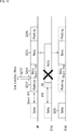
- FIG. 2 is a diagram illustrating communication between one AP and two STAs in a conventional wireless LAN system.
- step S11 while STA1 is transmitting a data packet to the AP, data to be transmitted to the AP with low delay (low-delay data) is generated in STA2 in step S12. .
- the STA 2 waits for the transmission of the data packet of the STA 1 to be completed, and observes whether or not the media can be used between the subsequent IFS (Inter Frame Spacing) and the CW (Contention Windows).
- IFS Inter Frame Spacing
- CW Contention Windows
- IFS is a fixed period for determining whether the channel is idle
- CW is a variable long period for avoiding data packet collision.
- the time length of a data packet may be on the order of milliseconds, while the time length of IFS or CW is on the order of tens of microseconds. That is, the length of the data packet is 100 times or more the waiting time such as IFS or CW.
- the delay time allowed in video transmission or the like is, for example, 10 ms or less from when low-delay data is generated inside the STA until the data packet is received by the AP.
- the time until the transmission of the data packet of the STA1 has a great effect on the data transmission by the STA2, which hinders the low-latency wireless communication.
- FIG. 3 is a diagram illustrating communication between one AP and two STAs in the wireless LAN system according to the present disclosure. Also in the example of FIG. 3, it is assumed that STA2 has low delay data.
- step S31 the STA2 transmits a low-latency request for data generated in its own device to the AP in advance.
- the low delay request includes an allowable delay time that may be required from the generation of data to the end of transmission.
- the low-delay request may further include a validity period indicating how long the low-delay request is valid.
- the allowable delay time is 10 ms
- the valid period of the low delay request is 10 minutes.
- step S32 the AP calculates the allowable resource occupation time in the wireless communication network (BSS) based on the allowable delay time included in the low delay request, and Max ⁇ Occupy ⁇ Announce To each STA.
- BSS wireless communication network
- the permissible resource occupancy time is the longest PPDU (PLCP Protocol Data Unit) time indicating the temporal length of data that can be accepted as the radio resource occupation time.
- the longest PPDU time is 5 ms.
- the AP may further notify each STA of a validity period indicating how long the restriction by the allowable resource occupation time is valid.
- the AP may further notify each STA of a band to be restricted by the allowable resource occupation time. .
- the band to be restricted is set to channel A, and the longest PPDU time is reported to each STA.
- the AP can also receive low-latency requests from multiple STAs. In this case, the AP calculates the allowable resource occupation time according to each low delay request.
- Each STA that has received the allowable resource occupation time (the longest PPDU time) notified by the AP generates data (PPDU) according to the restriction by the allowable resource occupation time.
- the STA1 when data to be transmitted to the AP is generated in the STA1 in step S33, the STA1 generates data with a PPDU time of 3 ms in step S34 after the lapse of the IFS and CW, and transmits the data to the AP in step S34. I do.
- the PPDU time of this data satisfies the restriction by the longest PPDU time (5 ms).
- step S34 while STA1 is transmitting data to the AP in step S34, low-delay data to be transmitted to the AP with low delay is generated inside STA2 in step S35 in step S35.
- the STA 2 waits for the end of the data transmission of the STA 1 and, after the lapse of the subsequent IFS and CW, starts transmitting its own data in step S36.
- the data transmitted from the STA1 has a PPDU time of 3 ms due to the limitation by the allowable resource occupation time. Accordingly, the STA 2 can transmit the low-delay data to the AP within 10 ms, which is the allowable delay time, from the occurrence of the low-delay data.
- FIG. 4 is a block diagram illustrating a functional configuration example of the AP.
- the AP 110 in FIG. 4 includes a data processing unit 111, a wireless communication unit 112, an antenna 113, and a control unit 114.
- the data processing unit 111 performs a process for transmitting and receiving data. Specifically, the data processing unit 111 generates a frame based on data from the communication upper layer, and provides the generated frame to the wireless communication unit 112. For example, the data processing unit 111 generates a frame (packet) from the data, and performs processing such as addition of a MAC header for media access control (MAC) to the generated frame and addition of an error detection code.
- MAC media access control
- the data processing unit 111 extracts data from the received frame, and provides the extracted data to a communication upper layer. For example, the data processing unit 111 acquires data by analyzing the MAC header, detecting and correcting a code error, performing reorder processing, and the like on the received frame.
- the wireless communication unit 112 has a signal processing function and a wireless interface function.
- the signal processing function is a function for performing signal processing such as modulation on a frame.
- the wireless communication unit 112 performs encoding, interleaving, and modulation on the frame from the data processing unit 111 according to the coding and modulation scheme set by the control unit 114, and adds a preamble and a PHY header. Thus, a symbol stream is generated.
- the wireless communication unit 112 obtains a frame by performing demodulation, decoding, and the like on the symbol stream obtained by the processing of the wireless interface function, and provides the obtained frame to the data processing unit 111 or the control unit 114.
- the wireless interface function is a function of transmitting and receiving signals via the antenna 113.
- the wireless communication unit 112 performs analog signal conversion, amplification, filtering, and frequency up-conversion on a signal related to the symbol stream obtained by the processing of the signal processing function. Then, wireless communication section 112 transmits the processed signal via antenna 113.
- the wireless communication unit 112 performs a process reverse to that at the time of signal transmission, such as frequency down-conversion and digital signal conversion, on a signal obtained from the antenna 113.
- the control unit 114 controls the operation of the AP 110 as a whole. Specifically, the control unit 114 performs processing such as transfer of information between functions, setting of communication parameters, and frame scheduling in the data processing unit 111.
- the control unit 114 includes the calculation unit 121 that calculates the above-described allowable resource occupation time (the longest PPDU time) in response to a low delay request from the STA.
- the AP 110 is provided with a storage unit that stores information used for processing of the data processing unit 111 and the control unit 114.
- the storage unit stores information stored in the transmission frame, information obtained from the reception frame, information on communication parameters, and the like.
- the AP 110 is also provided with a communication interface for performing communication with an external network.
- FIG. 5 is a block diagram illustrating a functional configuration example of the STA.
- the STA 130 in FIG. 5 includes a data processing unit 131, a wireless communication unit 132, an antenna 133, and a control unit 134.
- the data processing unit 131, the wireless communication unit 132, the antenna 133, and the control unit 134 have the same functions as the data processing unit 111, the wireless communication unit 112, the antenna 113, and the control unit 114 in FIG. Detailed description is omitted.
- the STA 130 is also provided with a storage unit for storing information used for processing of the data processing unit 131 and the control unit 134.
- step S111 the wireless communication unit 112 determines whether a low delay request has been received from the STA 130 in the BSS to which the wireless communication unit 112 belongs. The process of step S111 is repeated until it is determined that the low delay request has been received.
- step S112 the calculation unit 121 of the control unit 114 determines the allowable resource occupation time (longest PPDU time) based on the allowable delay time included in the received low delay request. calculate.
- step S113 the wireless communication unit 112 notifies (transmits) via the antenna 113 the allowed resource occupation time calculated by the calculation unit 121 to each STA 130 in the BSS to which the wireless communication unit 112 belongs.
- step S114 the control unit 114 controls each unit so as to perform communication with each STA 130 according to the restriction based on the allowable resource occupation time.
- step S121 the wireless communication unit 132 receives the allowed resource occupation time notified by the AP 110 via the antenna 133.
- control unit 134 controls each unit so as to perform communication according to the restriction based on the allowable resource occupation time.
- step S131 the wireless communication unit 132 transmits a low delay request to the AP 110 via the antenna 133.
- step S132 the wireless communication unit 132 receives the allowed resource occupation time notified by the AP 110 via the antenna 133.
- step S133 the data processing unit 111 determines whether low-delay data has occurred. The process of step S133 is repeated until it is determined that low-delay data has occurred.
- step S134 the wireless communication unit 132 transmits the generated low-latency data to the AP 110 via the antenna 133.
- the resource occupation time of each STA is limited according to the occurrence of low-latency data in the BSS. This makes it possible to more reliably realize low-delay wireless communication by the STA serving as a source of low-delay data when low-delay data to be transmitted with low delay is generated with priority.
- the AP may be the source of the low-delay data.
- the AP becomes a source of low-latency data in response to a low-latency request from an application, calculates an allowable resource occupation time in response to the low-latency request, and notifies the STA in the BSS.
- Interference by neighboring networks When one BSS formed by an AP and an STA is adjacent to another BSS formed by another AP and another STA, interference by another BSS may occur.
- 'BSS' communication is performed between AP 'and STA3.
- the STA2 may refrain from using the radio resources by the LBT function while the STA3 is communicating with the AP '.
- STA2 is a source of low-latency data
- the time until the end of data transmission by STA3 greatly affects data transmission by STA2, which hinders low-latency wireless communication.
- the AP wireless communication unit 112 forming the BSS allows the STA1 and STA2 in the BSS and also the AP 'forming the adjacent BSS' to have the allowable resource occupation time (longest). PPDU time).
- AP ⁇ notifies STA3 of the allowable resource occupation time notified by the AP. Accordingly, even in the BSS 'adjacent to the BSS, the resource occupation time of the STA3 is limited, so that it is possible to more reliably realize the low-delay wireless communication by the STA2.
- the STA1 may acquire the right to access the radio resource again and start transmitting the data.
- the low delay requirement of STA2 cannot be satisfied.
- a low-delay data source reserves a wireless resource to realize low-delay wireless communication.
- FIG. 11 is a diagram illustrating a first example of a configuration in which a source of low-delay data reserves a radio resource.
- the AP in response to a low-delay request from an application, transmits the low-delay data to the STA2 because the AP is a source of low-delay data.
- step S211 STA2 transmits data in the BSS.
- the AP determines in step S212 as a reservation signal for occupying the radio resource preferentially. Start sending Padding.
- Transmission of Padding is started at a timing according to the allowable delay time of the low-delay data included in the low-delay request by the application, regardless of whether or not there is data to be transmitted to STA2.
- the transmission of the padding is started at a timing based on the relationship with the allowable resource occupation time (the longest PPDU time) so that transmission of the low delay data to the STA 2 can be performed (completed) within the allowable delay time. Transmission of padding is repeatedly performed during the period when the AP occupies the radio resource.
- Data ⁇ Start ⁇ Indication is a signal for notifying the transmission destination that low-delay data has occurred.
- the AP After transmitting Data ⁇ Start ⁇ Indication, the AP transmits low-latency data in step S215. After that, in step S216, the AP repeatedly transmits the padding until the period for occupying the radio resource ends. That is, the AP inserts the Data ⁇ Start ⁇ Indication and the low-delay data into the reservation signal and transmits the reservation signal to the STA2.
- the AP reserves the radio resource, so that the low-delay wireless communication with the STA2 can be more reliably realized.
- FIG. 12 is a diagram illustrating a second example of a configuration in which a source of low-delay data reserves a radio resource.
- the STA2 that has transmitted the low-delay request is the source of the low-delay data, and the STA2 transmits the low-delay data to the AP.
- steps S231 to S234 in FIG. 12 is the same as the data flow in steps S31 to S34 in FIG. 3, and a description thereof will be omitted.
- step S235 After the data transmission by the STA1 in step S234 is completed and the Short IFS shorter than the IFS has elapsed, in step S235, the AP transmits a trigger frame to each STA.
- the trigger frame is a frame defined by IEEE 802.11ax for the AP to control the upstream communication from each STA.
- a trigger frame including information indicating that uplink communication from STA2 is preferentially performed is transmitted to each STA.
- the STA2 starts transmission of a reservation signal (Padding) for preferentially occupying the radio resource in step S236.
- the transmission of Padding is started at a timing according to the allowable delay time of the low-delay data included in the low-delay request, and is repeatedly performed while the STA2 occupies the radio resource.
- the STA2 transmits Data ⁇ Start ⁇ Indication in step S238.
- STA2 After transmitting Data ⁇ Start ⁇ Indication, STA2 transmits low-delay data in step S239. After that, in step S240, the STA 2 repeatedly transmits the padding until the period for occupying the radio resource ends. That is, the STA2 inserts Data ⁇ Start ⁇ Indication and low-delay data into the reservation signal and transmits the reservation signal to the AP.
- the STA2 reserves the radio resource, so that it is possible to more reliably realize the low-delay radio communication with the AP.
- the STA 130 may be realized as a mobile terminal such as a smartphone, a tablet PC (Personal Computer), a notebook PC, a portable game terminal, or a digital camera. Further, the STA 130 may be realized as a fixed terminal such as a television receiver, a printer, a digital scanner or a network storage, or an in-vehicle terminal such as a car navigation device.
- a mobile terminal such as a smartphone, a tablet PC (Personal Computer), a notebook PC, a portable game terminal, or a digital camera.
- the STA 130 may be realized as a fixed terminal such as a television receiver, a printer, a digital scanner or a network storage, or an in-vehicle terminal such as a car navigation device.
- the STA 130 is realized as a terminal (also referred to as an MTC (Machine Type Communication) terminal) that performs M2M (Machine To Machine) communication such as a smart meter, a vending machine, a remote monitoring device, or a POS (Point of Sale) terminal. You may. Further, the STA 130 may be a wireless communication module (for example, an integrated circuit module configured with one die) mounted on these terminals.
- MTC Machine Type Communication
- M2M Machine To Machine
- POS Point of Sale
- the AP 110 may be realized as a wireless LAN access point (also referred to as a wireless base station) having a router function or not having a router function. Further, the AP 110 may be realized as a mobile wireless LAN router. Further, the AP 110 may be a wireless communication module (for example, an integrated circuit module configured with one die) mounted on these devices.
- a wireless LAN access point also referred to as a wireless base station
- the AP 110 may be realized as a mobile wireless LAN router.
- the AP 110 may be a wireless communication module (for example, an integrated circuit module configured with one die) mounted on these devices.
- FIG. 13 is a block diagram illustrating an example of a schematic configuration of a smartphone 900 to which the technology according to the present disclosure is applied.
- the smartphone 900 includes a processor 901, a memory 902, a storage 903, an external connection interface 904, a camera 906, a sensor 907, a microphone 908, an input device 909, a display device 910, a speaker 911, a wireless communication interface 913, an antenna switch 914, an antenna 915, A bus 917, a battery 918, and an auxiliary controller 919 are provided.
- the processor 901 may be, for example, a CPU (Central Processing Unit) or a SoC (System on Chip), and controls functions of an application layer and other layers of the smartphone 900.
- the memory 902 includes a RAM (Random Access Memory) and a ROM (Read Only Memory), and stores programs and data executed by the processor 901.
- the storage 903 includes a storage medium such as a semiconductor memory or a hard disk.
- the external connection interface 904 is an interface for connecting an external device such as a memory card or a USB (Universal Serial Bus) device to the smartphone 900.
- the camera 906 has an image sensor such as a CCD (Charge Coupled Device) or a CMOS (Complementary Metal Oxide Semiconductor), and generates a captured image.
- the sensor 907 includes, for example, a sensor group such as a positioning sensor, a gyro sensor, a geomagnetic sensor, and an acceleration sensor.
- Microphone 908 converts audio input to smartphone 900 into an audio signal.
- the input device 909 includes, for example, a touch sensor that detects a touch on the screen of the display device 910, a keypad, a keyboard, a button or a switch, and receives an operation or information input from a user.
- the display device 910 has a screen such as a liquid crystal display (LCD) or an organic light emitting diode (OLED) display, and displays an output image of the smartphone 900.
- Speaker 911 converts an audio signal output from smartphone 900 into audio.
- the wireless communication interface 913 supports one or more of wireless LAN standards such as IEEE802.11a, 11b, 11g, 11n, 11ac, and 11ad, and executes wireless communication.
- the wireless communication interface 913 communicates with another device via a wireless LAN access point in the infrastructure mode.
- the wireless communication interface 913 directly communicates with another device in an ad hoc mode or a direct communication mode such as Wi-Fi Direct (registered trademark).
- Wi-Fi Direct unlike the ad hoc mode, one of the two terminals operates as an access point, but communication is performed directly between the terminals.
- the wireless communication interface 913 typically includes a baseband processor, an RF (Radio @ Frequency) circuit, a power amplifier, and the like.
- the wireless communication interface 913 may be a one-chip module in which a memory that stores a communication control program, a processor that executes the program, and related circuits are integrated.
- the wireless communication interface 913 may support another type of wireless communication scheme such as a short-range wireless communication scheme, a close proximity wireless communication scheme, or a cellular communication scheme, in addition to the wireless LAN scheme.
- the antenna switch 914 switches the connection destination of the antenna 915 among a plurality of circuits (for example, circuits for different wireless communication schemes) included in the wireless communication interface 913.
- the antenna 915 includes a single or a plurality of antenna elements (for example, a plurality of antenna elements configuring a MIMO antenna), and is used for transmission and reception of a wireless signal by the wireless communication interface 913.
- the smartphone 900 is not limited to the example in FIG. 13 and may include a plurality of antennas (for example, an antenna for a wireless LAN, an antenna for a close proximity wireless communication system, and the like).
- the antenna switch 914 may be omitted from the configuration of the smartphone 900.
- the bus 917 connects the processor 901, the memory 902, the storage 903, the external connection interface 904, the camera 906, the sensor 907, the microphone 908, the input device 909, the display device 910, the speaker 911, the wireless communication interface 913, and the auxiliary controller 919 to each other.
- the battery 918 supplies power to each block of the smartphone 900 via a power supply line partially indicated by a broken line in the drawing.
- the auxiliary controller 919 operates the minimum necessary functions of the smartphone 900 in, for example, the sleep mode.
- the data processing unit 131, the wireless communication unit 132, and the control unit 134 described with reference to FIG. 5 may be implemented in the wireless communication interface 913. Further, at least a part of these functions may be implemented in the processor 901 or the auxiliary controller 919.
- the smartphone 900 may operate as a wireless access point (software AP) by causing the processor 901 to execute an access point function at an application level. Further, the wireless communication interface 913 may have a wireless access point function.
- FIG. 14 is a block diagram illustrating an example of a schematic configuration of a car navigation device 920 to which the technology according to the present disclosure is applied.
- the car navigation device 920 includes a processor 921, a memory 922, a GPS (Global Positioning System) module 924, a sensor 925, a data interface 926, a content player 927, a storage medium interface 928, an input device 929, a display device 930, a speaker 931, and wireless communication.
- An interface 933, an antenna switch 934, an antenna 935, and a battery 938 are provided.
- the processor 921 may be, for example, a CPU or an SoC, and controls a navigation function and other functions of the car navigation device 920.
- the memory 922 includes a RAM and a ROM, and stores programs and data executed by the processor 921.
- the ⁇ ⁇ ⁇ ⁇ ⁇ GPS module 924 measures the position (eg, latitude, longitude, and altitude) of the car navigation device 920 using a GPS signal received from a GPS satellite.
- the sensor 925 includes a sensor group such as a gyro sensor, a geomagnetic sensor, and a barometric pressure sensor.
- the data interface 926 is connected to the in-vehicle network 941 via a terminal (not shown), for example, and acquires data generated on the vehicle side such as vehicle speed data.
- the content player 927 reproduces the content stored on the storage medium (for example, CD or DVD) inserted into the storage medium interface 928.
- the input device 929 includes, for example, a touch sensor, a button, or a switch that detects a touch on the screen of the display device 930, and receives an operation or information input from a user.
- the display device 930 has a screen such as an LCD or an OLED display, and displays a navigation function or an image of a content to be reproduced.
- the speaker 931 outputs the navigation function or the sound of the content to be reproduced.
- the wireless communication interface 933 supports one or more of wireless LAN standards such as IEEE802.11a, 11b, 11g, 11n, 11ac, and 11ad, and executes wireless communication.
- the wireless communication interface 933 communicates with another device via the wireless LAN access point in the infrastructure mode.
- the wireless communication interface 933 directly communicates with another device in a direct communication mode such as an ad hoc mode or Wi-Fi @ Direct.
- the wireless communication interface 933 typically includes a baseband processor, an RF circuit, a power amplifier, and the like.
- the wireless communication interface 933 may be a one-chip module in which a memory that stores a communication control program, a processor that executes the program, and related circuits are integrated.
- the wireless communication interface 933 may support another type of wireless communication scheme such as a short-range wireless communication scheme, a close proximity wireless communication scheme, or a cellular communication scheme in addition to the wireless LAN scheme.
- the antenna switch 934 switches a connection destination of the antenna 935 among a plurality of circuits included in the wireless communication interface 933.
- the antenna 935 includes a single or a plurality of antenna elements, and is used for transmission and reception of a wireless signal by the wireless communication interface 933.
- the present invention is not limited to the example of FIG. 14, and the car navigation device 920 may include a plurality of antennas.
- the antenna switch 934 may be omitted from the configuration of the car navigation device 920.
- the battery 938 supplies power to each block of the car navigation device 920 via a power supply line partially indicated by a broken line in the drawing.
- the battery 938 stores power supplied from the vehicle.
- the data processing unit 131, the wireless communication unit 132, and the control unit 134 described with reference to FIG. At least a part of these functions may be implemented in the processor 921.
- the wireless communication interface 933 may operate as the above-described AP 110 and provide a wireless connection to a terminal of a user in the vehicle.
- the technology according to the present disclosure may be implemented as an in-vehicle system (or vehicle) 940 including one or more blocks of the above-described car navigation device 920, an in-vehicle network 941, and a vehicle-side module 942.
- vehicle-side module 942 generates vehicle-side data such as vehicle speed, engine speed, and failure information, and outputs the generated data to the vehicle-mounted network 941.
- FIG. 15 is a block diagram illustrating an example of a schematic configuration of a wireless access point 950 to which the technology according to the present disclosure is applied.
- the wireless access point 950 includes a controller 951, a memory 952, an input device 954, a display device 955, a network interface 957, a wireless communication interface 963, an antenna switch 964, and an antenna 965.
- the controller 951 may be, for example, a CPU or a DSP (Digital Signal Processor), and various functions (for example, access restriction, routing, encryption, and firewall) of the IP (Internet Protocol) layer and higher layers of the wireless access point 950. , And log management).
- the memory 952 includes a RAM and a ROM, and stores a program executed by the controller 951 and various control data (for example, a terminal list, a routing table, an encryption key, a security setting, a log, and the like).
- the input device 954 includes, for example, a button or a switch, and receives an operation from a user.
- the display device 955 includes an LED lamp and the like, and displays an operation status of the wireless access point 950.
- the network interface 957 is a wired communication interface for the wireless access point 950 to connect to the wired communication network 958.
- the network interface 957 may have a plurality of connection terminals.
- the wired communication network 958 may be a LAN such as Ethernet (registered trademark), or may be a WAN (Wide Area Network).
- the wireless communication interface 963 supports one or more of wireless LAN standards such as IEEE802.11a, 11b, 11g, 11n, 11ac, and 11ad, and provides wireless connection as an access point to nearby terminals.
- the wireless communication interface 963 typically includes a baseband processor, an RF circuit, a power amplifier, and the like.
- the wireless communication interface 963 may be a one-chip module in which a memory that stores a communication control program, a processor that executes the program, and related circuits are integrated.
- the antenna switch 964 switches a connection destination of the antenna 965 among a plurality of circuits included in the wireless communication interface 963.
- the antenna 965 has a single or a plurality of antenna elements, and is used for transmission and reception of a wireless signal by the wireless communication interface 963.
- the data processing unit 111, the wireless communication unit 112, and the control unit 114 described using FIG. 4 may be implemented in the wireless communication interface 963. Further, at least a part of these functions may be implemented in the controller 951.
- the technology according to the present disclosure can have the following configurations.
- a calculating unit that calculates an allowable resource occupation time in the wireless communication network in response to a low-delay request for data generated in the wireless communication network to which the own device belongs;
- a wireless communication unit that notifies the calculated allowable resource occupation time to a wireless communication device in the wireless communication network.
- the low delay request includes an allowable delay time of the data,
- the wireless communication control device according to (1), wherein the calculation unit calculates the allowable resource occupation time based on the allowable delay time.
- the wireless communication control device according to (2), wherein the low delay request further includes a validity period of the low delay request.
- the wireless communication unit when the own device is a source of the data, transmits a reservation signal for the own device to preferentially occupy a wireless resource to a destination device that is a destination of the data.
- the wireless communication control device according to any one of (1) to (6).
- the wireless communication control device is According to a low-delay request for data generated in the wireless communication network to which the own device belongs, calculate an allowable resource occupation time in the wireless communication network, A wireless communication control method for notifying a wireless communication device in the wireless communication network of the calculated allowable resource occupation time.
- a wireless communication unit that receives the allowable resource occupation time notified by the wireless communication control device in response to a low delay request of data generated in the wireless communication network to which the own device belongs, The wireless communication device, wherein the wireless communication unit performs wireless communication in accordance with the restriction by the allowable resource occupation time.
- the wireless communication device according to (14) wherein the wireless communication unit transmits the low delay request to a wireless communication control device when the own device is a source of the data.
- the wireless communication device Receiving the allowable resource occupation time notified by the wireless communication control device in response to a low delay request of data generated in the wireless communication network to which the own device belongs, A wireless communication method for performing wireless communication in accordance with the restriction by the allowable resource occupation time.
- ⁇ 110 ⁇ AP ⁇ 111 ⁇ data processing unit, ⁇ 112 ⁇ wireless communication unit, ⁇ 114 ⁇ control unit, ⁇ 121 ⁇ calculation unit, ⁇ 130 ⁇ STA, ⁇ 131 ⁇ data processing unit, ⁇ 132 ⁇ wireless communication unit, ⁇ 134 ⁇ control unit
Abstract
Description
2.装置の構成と動作
3.隣接ネットワークによる干渉
4.無線リソースの予約
5.応用例
(無線LANシステムの構成)
図1は、本開示の実施の形態に係る無線LANシステムの構成例を示す図である。
近年、VRやARにおける超高画質映像の伝送や、ロボットなどの精密機器の遠隔操作のために、低遅延の無線通信が必要とされている。
図3は、本開示の無線LANシステムにおける、1台のAPと2台のSTAの通信について説明する図である。図3の例においても、STA2が低遅延データを有するものとする。
以下においては、上述した無線LANシステムを構成する装置の構成と動作について説明する。
図4は、APの機能構成例を示すブロック図である。
図5は、STAの機能構成例を示すブロック図である。
まず、図6のフローチャートを参照して、本開示の無線LANシステムにおけるAP110の動作について説明する。
次に、図7のフローチャートを参照して、本開示の無線LANシステムにおけるSTA130の動作について説明する。図7の処理は、AP110によって許容リソース占有時間が通知されたときの各STA130の動作である。
ところで、APとSTAにより形成される1つのBSSに、他のAPと他のSTAにより形成される他のBSSが隣接する場合、他のBSSによる干渉が発生するおそれがある。
ところで、IEEE 802.11により定義される通信プロトコルでは、端末間の公平性を保つため、自律分散的かつランダムに、無線リソースの割り当てが行われる。そのため、上述したリソース占有時間の制限のみでは、低遅延の無線通信を実現するのに十分でない場合がある。
図11は、低遅延データの発生源が無線リソースを予約する構成の第1の例について説明する図である。
図12は、低遅延データの発生源が無線リソースを予約する構成の第2の例について説明する図である。
以下においては、本開示の応用例について説明する。
図13は、本開示に係る技術が適用されるスマートフォン900の概略的な構成の一例を示すブロック図である。スマートフォン900は、プロセッサ901、メモリ902、ストレージ903、外部接続インタフェース904、カメラ906、センサ907、マイクロフォン908、入力デバイス909、表示デバイス910、スピーカ911、無線通信インタフェース913、アンテナスイッチ914、アンテナ915、バス917、バッテリー918、および補助コントローラ919を備える。
図14は、本開示に係る技術が適用されるカーナビゲーション装置920の概略的な構成の一例を示すブロック図である。カーナビゲーション装置920は、プロセッサ921、メモリ922、GPS(Global Positioning System)モジュール924、センサ925、データインタフェース926、コンテンツプレーヤ927、記憶媒体インタフェース928、入力デバイス929、表示デバイス930、スピーカ931、無線通信インタフェース933、アンテナスイッチ934、アンテナ935、およびバッテリー938を備える。
図15は、本開示に係る技術が適用される無線アクセスポイント950の概略的な構成の一例を示すブロック図である。無線アクセスポイント950は、コントローラ951、メモリ952、入力デバイス954、表示デバイス955、ネットワークインタフェース957、無線通信インタフェース963、アンテナスイッチ964、およびアンテナ965を備える。
(1)
自装置が属する無線通信ネットワーク内で発生するデータの低遅延要求に応じて、前記無線通信ネットワークにおける許容リソース占有時間を算出する算出部と、
算出された前記許容リソース占有時間を、前記無線通信ネットワーク内の無線通信装置に通知する無線通信部と
を備える無線通信制御装置。
(2)
前記低遅延要求は、前記データの許容遅延時間を含み、
前記算出部は、前記許容遅延時間に基づいて、前記許容リソース占有時間を算出する
(1)に記載の無線通信制御装置。
(3)
前記低遅延要求は、前記低遅延要求の有効期間をさらに含む
(2)に記載の無線通信制御装置。
(4)
前記無線通信部は、前記無線通信ネットワーク内の前記無線通信装置に、前記許容リソース占有時間による制限の有効期間をさらに通知する
(1)乃至(3)のいずれかに記載の無線通信制御装置。
(5)
前記無線通信部は、前記無線通信ネットワーク内の前記無線通信装置に、前記許容リソース占有時間による制限の対象となる帯域をさらに通知する
(1)乃至(4)のいずれかに記載の無線通信制御装置。
(6)
前記無線通信部は、前記許容リソース占有時間を、他の無線通信ネットワークを形成する他の無線通信制御装置にも通知する
(1)乃至(5)のいずれかに記載の無線通信制御装置。
(7)
前記無線通信部は、前記自装置が前記データの発生源となる場合、前記自装置が優先的に無線リソースを占有するための予約信号を、前記データの送信先となる送信先装置に送信する
(1)乃至(6)のいずれかに記載の無線通信制御装置。
(8)
前記無線通信部は、前記低遅延要求に含まれる前記データの許容遅延時間に応じたタイミングで、前記予約信号を前記送信先装置に送信する
(7)に記載の無線通信制御装置。
(9)
前記無線通信部は、前記自装置において前記データが発生したとき、前記予約信号に前記データを挿入して、前記送信先装置に送信する
(7)または(8)に記載の無線通信制御装置。
(10)
前記無線通信部は、前記無線通信ネットワーク内の前記無線通信装置のうちの要求元装置から前記低遅延要求を受信する
(1)乃至(6)のいずれかに記載の無線通信制御装置。
(11)
前記無線通信部は、前記要求元装置が優先的に無線リソースを占有するための予約信号を、前記要求元装置から受信する
(10)に記載の無線通信制御装置。
(12)
前記無線通信部は、前記要求元装置において前記データが発生したとき、前記予約信号に挿入された前記データを、前記要求元装置から受信する
(11)に記載の無線通信制御装置。
(13)
無線通信制御装置が、
自装置が属する無線通信ネットワーク内で発生するデータの低遅延要求に応じて、前記無線通信ネットワークにおける許容リソース占有時間を算出し、
算出された前記許容リソース占有時間を、前記無線通信ネットワーク内の無線通信装置に通知する
無線通信制御方法。
(14)
自装置が属する無線通信ネットワーク内で発生するデータの低遅延要求に応じて無線通信制御装置により通知された許容リソース占有時間を受信する無線通信部を備え、
前記無線通信部は、前記許容リソース占有時間による制限に従って無線通信を行う
無線通信装置。
(15)
前記無線通信部は、前記自装置が前記データの発生源となる場合、前記低遅延要求を無線通信制御装置に送信する
(14)に記載の無線通信装置。
(16)
前記無線通信部は、前記自装置が優先的に無線リソースを占有するための予約信号を、前記無線通信制御装置にさらに送信する
(15)に記載の無線通信装置。
(17)
前記無線通信部は、前記低遅延要求に含まれる前記データの許容遅延時間に応じたタイミングで、前記予約信号を前記無線通信制御装置に送信する
(16)に記載の無線通信装置。
(18)
前記無線通信部は、前記自装置において前記データが発生したとき、前記予約信号に前記データを挿入して、前記無線通信制御装置に送信する
(16)または(17)に記載の無線通信装置。
(19)
無線通信装置が、
自装置が属する無線通信ネットワーク内で発生するデータの低遅延要求に応じて無線通信制御装置により通知された許容リソース占有時間を受信し、
前記許容リソース占有時間による制限に従って無線通信を行う
無線通信方法。
Claims (19)
- 自装置が属する無線通信ネットワーク内で発生するデータの低遅延要求に応じて、前記無線通信ネットワークにおける許容リソース占有時間を算出する算出部と、
算出された前記許容リソース占有時間を、前記無線通信ネットワーク内の無線通信装置に通知する無線通信部と
を備える無線通信制御装置。 - 前記低遅延要求は、前記データの許容遅延時間を含み、
前記算出部は、前記許容遅延時間に基づいて、前記許容リソース占有時間を算出する
請求項1に記載の無線通信制御装置。 - 前記低遅延要求は、前記低遅延要求の有効期間をさらに含む
請求項2に記載の無線通信制御装置。 - 前記無線通信部は、前記無線通信ネットワーク内の前記無線通信装置に、前記許容リソース占有時間による制限の有効期間をさらに通知する
請求項1に記載の無線通信制御装置。 - 前記無線通信部は、前記無線通信ネットワーク内の前記無線通信装置に、前記許容リソース占有時間による制限の対象となる帯域をさらに通知する
請求項1に記載の無線通信制御装置。 - 前記無線通信部は、前記許容リソース占有時間を、他の無線通信ネットワークを形成する他の無線通信制御装置にも通知する
請求項1に記載の無線通信制御装置。 - 前記無線通信部は、前記自装置が前記データの発生源となる場合、前記自装置が優先的に無線リソースを占有するための予約信号を、前記データの送信先となる送信先装置に送信する
請求項1に記載の無線通信制御装置。 - 前記無線通信部は、前記低遅延要求に含まれる前記データの許容遅延時間に応じたタイミングで、前記予約信号を前記送信先装置に送信する
請求項7に記載の無線通信制御装置。 - 前記無線通信部は、前記自装置において前記データが発生したとき、前記予約信号に前記データを挿入して、前記送信先装置に送信する
請求項7に記載の無線通信制御装置。 - 前記無線通信部は、前記無線通信ネットワーク内の前記無線通信装置のうちの要求元装置から前記低遅延要求を受信する
請求項1に記載の無線通信制御装置。 - 前記無線通信部は、前記要求元装置が優先的に無線リソースを占有するための予約信号を、前記要求元装置から受信する
請求項10に記載の無線通信制御装置。 - 前記無線通信部は、前記要求元装置において前記データが発生したとき、前記予約信号に挿入された前記データを、前記要求元装置から受信する
請求項11に記載の無線通信制御装置。 - 無線通信制御装置が、
自装置が属する無線通信ネットワーク内で発生するデータの低遅延要求に応じて、前記無線通信ネットワークにおける許容リソース占有時間を算出し、
算出された前記許容リソース占有時間を、前記無線通信ネットワーク内の無線通信装置に通知する
無線通信制御方法。 - 自装置が属する無線通信ネットワーク内で発生するデータの低遅延要求に応じて無線通信制御装置により通知された許容リソース占有時間を受信する無線通信部を備え、
前記無線通信部は、前記許容リソース占有時間による制限に従って無線通信を行う
無線通信装置。 - 前記無線通信部は、前記自装置が前記データの発生源となる場合、前記低遅延要求を無線通信制御装置に送信する
請求項14に記載の無線通信装置。 - 前記無線通信部は、前記自装置が優先的に無線リソースを占有するための予約信号を、前記無線通信制御装置にさらに送信する
請求項15に記載の無線通信装置。 - 前記無線通信部は、前記低遅延要求に含まれる前記データの許容遅延時間に応じたタイミングで、前記予約信号を前記無線通信制御装置に送信する
請求項16に記載の無線通信装置。 - 前記無線通信部は、前記自装置において前記データが発生したとき、前記予約信号に前記データを挿入して、前記無線通信制御装置に送信する
請求項16に記載の無線通信装置。 - 無線通信装置が、
自装置が属する無線通信ネットワーク内で発生するデータの低遅延要求に応じて無線通信制御装置により通知された許容リソース占有時間を受信し、
前記許容リソース占有時間による制限に従って無線通信を行う
無線通信方法。
Priority Applications (3)
| Application Number | Priority Date | Filing Date | Title |
|---|---|---|---|
| EP19857050.9A EP3833148B1 (en) | 2018-09-03 | 2019-08-20 | Wireless communication control device, wireless communication control method, wireless communication device, and wireless communication method |
| US17/267,809 US11452114B2 (en) | 2018-09-03 | 2019-08-20 | Wireless communication control device, wireless communication control method, wireless communication device, and wireless communication method |
| JP2020541112A JP7392648B2 (ja) | 2018-09-03 | 2019-08-20 | 無線通信制御装置、無線通信制御方法、無線通信装置、および無線通信方法 |
Applications Claiming Priority (2)
| Application Number | Priority Date | Filing Date | Title |
|---|---|---|---|
| JP2018-164372 | 2018-09-03 | ||
| JP2018164372 | 2018-09-03 |
Publications (1)
| Publication Number | Publication Date |
|---|---|
| WO2020049997A1 true WO2020049997A1 (ja) | 2020-03-12 |
Family
ID=69722910
Family Applications (1)
| Application Number | Title | Priority Date | Filing Date |
|---|---|---|---|
| PCT/JP2019/032355 WO2020049997A1 (ja) | 2018-09-03 | 2019-08-20 | 無線通信制御装置、無線通信制御方法、無線通信装置、および無線通信方法 |
Country Status (5)
| Country | Link |
|---|---|
| US (1) | US11452114B2 (ja) |
| EP (1) | EP3833148B1 (ja) |
| JP (1) | JP7392648B2 (ja) |
| TW (1) | TWI829745B (ja) |
| WO (1) | WO2020049997A1 (ja) |
Families Citing this family (1)
| Publication number | Priority date | Publication date | Assignee | Title |
|---|---|---|---|---|
| WO2020202388A1 (ja) * | 2019-03-29 | 2020-10-08 | 本田技研工業株式会社 | 制御装置、端末装置、制御方法、及びプログラム |
Citations (4)
| Publication number | Priority date | Publication date | Assignee | Title |
|---|---|---|---|---|
| JP2008072700A (ja) * | 2006-08-18 | 2008-03-27 | Hitachi Communication Technologies Ltd | 無線基地局、無線端末および無線通信システムにおける通信制御方法 |
| JP2016507183A (ja) * | 2013-01-11 | 2016-03-07 | インターデイジタル パテント ホールディングス インコーポレイテッド | Wlanオーバラッピング基本サービスセットのネットワーク内での通信のための方法および装置 |
| WO2016080335A1 (ja) * | 2014-11-18 | 2016-05-26 | 株式会社 東芝 | 無線通信用集積回路、無線通信端末および無線通信方法 |
| WO2016178418A1 (ja) * | 2015-05-07 | 2016-11-10 | 株式会社 東芝 | 無線通信端末および無線通信方法 |
Family Cites Families (4)
| Publication number | Priority date | Publication date | Assignee | Title |
|---|---|---|---|---|
| US8855088B2 (en) * | 2010-12-22 | 2014-10-07 | Intel Corporation | Reverse protocol for low latency wireless applications |
| US9521694B2 (en) * | 2012-06-18 | 2016-12-13 | Lg Electronics Inc. | Method and apparatus for initial access distribution over wireless LAN |
| US10396967B2 (en) * | 2016-09-29 | 2019-08-27 | Samsung Electronics Co., Ltd. | Method and apparatus for managing downlink to uplink interference in wireless communication system |
| US10841950B2 (en) * | 2018-05-21 | 2020-11-17 | Qualcomm Incorporated | Listen before talk techniques in shared millimeter wave radio frequency spectrum |
-
2019
- 2019-08-20 WO PCT/JP2019/032355 patent/WO2020049997A1/ja active Application Filing
- 2019-08-20 US US17/267,809 patent/US11452114B2/en active Active
- 2019-08-20 JP JP2020541112A patent/JP7392648B2/ja active Active
- 2019-08-20 EP EP19857050.9A patent/EP3833148B1/en active Active
- 2019-08-23 TW TW108130178A patent/TWI829745B/zh active
Patent Citations (4)
| Publication number | Priority date | Publication date | Assignee | Title |
|---|---|---|---|---|
| JP2008072700A (ja) * | 2006-08-18 | 2008-03-27 | Hitachi Communication Technologies Ltd | 無線基地局、無線端末および無線通信システムにおける通信制御方法 |
| JP2016507183A (ja) * | 2013-01-11 | 2016-03-07 | インターデイジタル パテント ホールディングス インコーポレイテッド | Wlanオーバラッピング基本サービスセットのネットワーク内での通信のための方法および装置 |
| WO2016080335A1 (ja) * | 2014-11-18 | 2016-05-26 | 株式会社 東芝 | 無線通信用集積回路、無線通信端末および無線通信方法 |
| WO2016178418A1 (ja) * | 2015-05-07 | 2016-11-10 | 株式会社 東芝 | 無線通信端末および無線通信方法 |
Also Published As
| Publication number | Publication date |
|---|---|
| JPWO2020049997A1 (ja) | 2021-08-26 |
| US11452114B2 (en) | 2022-09-20 |
| US20210168825A1 (en) | 2021-06-03 |
| EP3833148A1 (en) | 2021-06-09 |
| EP3833148A4 (en) | 2021-10-20 |
| JP7392648B2 (ja) | 2023-12-06 |
| TW202015460A (zh) | 2020-04-16 |
| EP3833148B1 (en) | 2023-09-27 |
| TWI829745B (zh) | 2024-01-21 |
Similar Documents
| Publication | Publication Date | Title |
|---|---|---|
| WO2016002263A1 (ja) | 無線通信装置、無線通信方法及びプログラム | |
| JP7074216B2 (ja) | 情報処理装置および情報処理方法 | |
| US11678222B2 (en) | Communication device, communication method, and program | |
| JP2022000985A (ja) | 情報処理装置、情報処理方法、および、プログラム | |
| RU2744980C2 (ru) | Беспроводное устройство, устройство связи, беспроводной способ управления, способ управления связью и программа | |
| JP7392648B2 (ja) | 無線通信制御装置、無線通信制御方法、無線通信装置、および無線通信方法 | |
| JP6578831B2 (ja) | 無線通信装置および無線通信方法 | |
| US11240845B2 (en) | Communication device, program, and communication method related to frame exchange | |
| EP3567968B1 (en) | Communication device and communication method | |
| RU2733801C1 (ru) | Устройство беспроводной связи и способ беспроводной связи | |
| US20200037290A1 (en) | Communication apparatus, communication method, and program | |
| WO2019097881A1 (ja) | 通信装置、通信システム |
Legal Events
| Date | Code | Title | Description |
|---|---|---|---|
| 121 | Ep: the epo has been informed by wipo that ep was designated in this application |
Ref document number: 19857050 Country of ref document: EP Kind code of ref document: A1 |
|
| ENP | Entry into the national phase |
Ref document number: 2020541112 Country of ref document: JP Kind code of ref document: A |
|
| NENP | Non-entry into the national phase |
Ref country code: DE |
|
| ENP | Entry into the national phase |
Ref document number: 2019857050 Country of ref document: EP Effective date: 20210305 |
|
| WWE | Wipo information: entry into national phase |
Ref document number: 2021104160 Country of ref document: RU |