WO2020049916A1 - クライオポンプおよびクライオパネル - Google Patents
クライオポンプおよびクライオパネル Download PDFInfo
- Publication number
- WO2020049916A1 WO2020049916A1 PCT/JP2019/030302 JP2019030302W WO2020049916A1 WO 2020049916 A1 WO2020049916 A1 WO 2020049916A1 JP 2019030302 W JP2019030302 W JP 2019030302W WO 2020049916 A1 WO2020049916 A1 WO 2020049916A1
- Authority
- WO
- WIPO (PCT)
- Prior art keywords
- cryopanel
- cryopump
- substrate
- gas
- stage
- Prior art date
- Legal status (The legal status is an assumption and is not a legal conclusion. Google has not performed a legal analysis and makes no representation as to the accuracy of the status listed.)
- Ceased
Links
Images



Classifications
-
- F—MECHANICAL ENGINEERING; LIGHTING; HEATING; WEAPONS; BLASTING
- F04—POSITIVE - DISPLACEMENT MACHINES FOR LIQUIDS; PUMPS FOR LIQUIDS OR ELASTIC FLUIDS
- F04B—POSITIVE-DISPLACEMENT MACHINES FOR LIQUIDS; PUMPS
- F04B37/00—Pumps having pertinent characteristics not provided for in, or of interest apart from, groups F04B25/00 - F04B35/00
- F04B37/06—Pumps having pertinent characteristics not provided for in, or of interest apart from, groups F04B25/00 - F04B35/00 for evacuating by thermal means
- F04B37/08—Pumps having pertinent characteristics not provided for in, or of interest apart from, groups F04B25/00 - F04B35/00 for evacuating by thermal means by condensing or freezing, e.g. cryogenic pumps
-
- F—MECHANICAL ENGINEERING; LIGHTING; HEATING; WEAPONS; BLASTING
- F05—INDEXING SCHEMES RELATING TO ENGINES OR PUMPS IN VARIOUS SUBCLASSES OF CLASSES F01-F04
- F05B—INDEXING SCHEME RELATING TO WIND, SPRING, WEIGHT, INERTIA OR LIKE MOTORS, TO MACHINES OR ENGINES FOR LIQUIDS COVERED BY SUBCLASSES F03B, F03D AND F03G
- F05B2210/00—Working fluid
- F05B2210/10—Kind or type
- F05B2210/12—Kind or type gaseous, i.e. compressible
Definitions
- the present invention relates to a cryopump and a cryopanel.
- a cryopump is a vacuum pump that captures and exhausts gas molecules by condensing or adsorbing on a cryopanel cooled to an extremely low temperature.
- a cryopump is generally used to realize a clean vacuum environment required for a semiconductor circuit manufacturing process or the like. Since the cryopump is a so-called gas accumulation type vacuum pump, it needs to be regenerated by periodically discharging trapped gas to the outside.
- cryopump during the evacuation operation, certain gases that are difficult to discharge even during regeneration flow into the cryopump and condense and adhere to the cryopanel, which contaminates the cryopanel. Can be done. Contaminated cryopanel may need to be disassembled and cleaned from the cryopump during cryopump maintenance. The cleaned cryopanel is reassembled and used when it can be reused. If it cannot be reused, it is discarded and replaced with a new cryopanel. In any case, such maintenance is troublesome.
- One of the exemplary purposes of an embodiment of the present invention is to facilitate maintenance of a cryopump.
- the cryopump includes an exposed region where exhaust gas can linearly reach through the cryopump inlet, and an unexposed region where exhaust gas cannot reach linearly through the cryopump inlet.
- a cryopanel assembly comprising: The non-exposed area has an adsorption area capable of adsorbing non-condensable gas, and the exposed area is covered with a removable protective surface.
- a cryopanel includes a cryopanel substrate and a removable protective surface that covers at least a part of the cryopanel substrate.
- FIG. 1 schematically illustrates a cryopump according to one embodiment.
- FIG. 2 is a schematic perspective view of an exemplary cryopanel that can be used in the cryopump shown in FIG. 1.
- FIG. 2 is a schematic perspective view of another exemplary cryopanel that can be used in the cryopump shown in FIG. 1.
- FIG. 4 is a schematic top view of yet another exemplary cryopanel that may be used in the cryopump shown in FIG. 1.
- FIG. 1 schematically shows a cryopump 10 according to an embodiment.
- the cryopump 10 is attached to, for example, a vacuum chamber of an ion implantation apparatus, a sputtering apparatus, a vapor deposition apparatus, or another vacuum processing apparatus to increase the degree of vacuum inside the vacuum chamber to a level required for a desired vacuum process. used.
- the cryopump 10 has a cryopump suction port (hereinafter, also simply referred to as “suction port”) 12 for receiving a gas to be evacuated from the vacuum chamber. Gas enters the internal space 14 of the cryopump 10 through the intake port 12.
- the axial direction of the cryopump 10 indicates a direction passing through the intake port 12 (that is, a direction along the central axis C in the drawing), and the radial direction is a direction along the intake port 12 (a first direction in a plane perpendicular to the central axis C). ).
- a position relatively close to the intake port 12 in the axial direction may be referred to as “up” and a position relatively far from the intake port 12 may be referred to as “down”.
- a position relatively far from the bottom of the cryopump 10 may be referred to as “up”, and a position relatively close to the bottom may be referred to as “down”.
- a position close to the center of the intake port 12 may be called “inside”
- a position close to the periphery of the intake port 12 may be called “outside”. Note that these expressions have nothing to do with the arrangement when the cryopump 10 is attached to the vacuum chamber.
- the cryopump 10 may be attached to the vacuum chamber with the intake port 12 facing downward in the vertical direction.
- a direction surrounding the axial direction may be referred to as a “circumferential direction”.
- the circumferential direction is a second direction along the intake port 12 (a second direction on a plane perpendicular to the central axis C), and is a tangential direction orthogonal to the radial direction.
- the cryopump 10 includes a refrigerator 16, a first-stage cryopanel 18, a second-stage cryopanel assembly 20, and a cryopump housing 70.
- the first-stage cryopanel 18 may be referred to as a high-temperature cryopanel portion or a 100K portion.
- the second-stage cryopanel assembly 20 may be referred to as a low-temperature cryopanel portion or a 10K portion.
- the refrigerator 16 is a cryogenic refrigerator such as a Gifford McMahon refrigerator (so-called GM refrigerator).
- the refrigerator 16 is a two-stage refrigerator. Therefore, the refrigerator 16 includes a first cooling stage 22 and a second cooling stage 24.
- the refrigerator 16 is configured to cool the first cooling stage 22 to a first cooling temperature and cool the second cooling stage 24 to a second cooling temperature.
- the second cooling temperature is lower than the first cooling temperature.
- the first cooling stage 22 is cooled to about 65K to 120K, preferably 80K to 100K
- the second cooling stage 24 is cooled to about 10K to 20K.
- the first cooling stage 22 and the second cooling stage 24 may be referred to as a high-temperature cooling stage and a low-temperature cooling stage, respectively.
- the refrigerator 16 further includes a refrigerator structure 21 that structurally supports the second cooling stage 24 on the first cooling stage 22 and structurally supports the first cooling stage 22 on the room temperature portion 26 of the refrigerator 16.
- the refrigerator structure 21 includes a first cylinder 23 and a second cylinder 25 that extend coaxially in the radial direction.
- the first cylinder 23 connects the room temperature part 26 of the refrigerator 16 to the first cooling stage 22.
- the second cylinder 25 connects the first cooling stage 22 to the second cooling stage 24.
- the room temperature section 26, the first cylinder 23, the first cooling stage 22, the second cylinder 25, and the second cooling stage 24 are linearly arranged in this order.
- a first displacer and a second displacer are reciprocally disposed inside the first cylinder 23 and the second cylinder 25, respectively.
- a first regenerator and a second regenerator are incorporated in the first displacer and the second displacer, respectively.
- the room temperature section 26 has a drive mechanism (not shown) for reciprocating the first displacer and the second displacer.
- the drive mechanism includes a flow path switching mechanism that switches the flow path of the working gas so as to periodically supply and discharge the working gas (for example, helium) to the inside of the refrigerator 16.
- the refrigerator 16 is connected to a compressor (not shown) for working gas.
- the refrigerator 16 cools the first cooling stage 22 and the second cooling stage 24 by expanding the working gas pressurized by the compressor therein.
- the expanded working gas is recovered by the compressor and pressurized again.
- the refrigerator 16 generates refrigeration by repeating a thermodynamic cycle (for example, a refrigeration cycle such as a GM cycle) including supply and discharge of the working gas and reciprocation of the first displacer and the second displacer in synchronization with the supply and discharge of the working gas.
- a thermodynamic cycle for example, a refrigeration cycle such as a GM cycle
- the illustrated cryopump 10 is a so-called horizontal cryopump.
- the horizontal cryopump is generally a cryopump in which the refrigerator 16 is disposed so as to intersect (usually perpendicular to) the central axis C of the cryopump 10.
- the first-stage cryopanel 18 includes a radiation shield 30 and an entrance cryopanel 32, and surrounds the second-stage cryopanel assembly 20.
- the first-stage cryopanel 18 provides a cryogenic surface for protecting the second-stage cryopanel assembly 20 from radiant heat outside the cryopump 10 or from the cryopump housing 70.
- the first cryopanel 18 is thermally coupled to the first cooling stage 22. Therefore, the first stage cryopanel 18 is cooled to the first cooling temperature.
- the first-stage cryopanel 18 has a gap between itself and the second-stage cryopanel assembly 20, and the first-stage cryopanel 18 is not in contact with the second-stage cryopanel assembly 20.
- the first stage cryopanel 18 is not in contact with the cryopump housing 70.
- the radiation shield 30 is provided to protect the second-stage cryopanel assembly 20 from radiation heat of the cryopump housing 70.
- the radiation shield 30 extends in a cylindrical shape (for example, a cylindrical shape) in the axial direction from the intake port 12.
- the radiation shield 30 is located between the cryopump housing 70 and the second cryopanel assembly 20 and surrounds the second cryopanel assembly 20.
- the radiation shield 30 has a shield main opening 34 for receiving gas from outside the cryopump 10 into the internal space 14.
- the shield main opening 34 is located at the intake port 12.
- the radiation shield 30 includes a shield front end 36 that defines the shield main opening 34, a shield bottom 38 located on the opposite side of the shield main opening 34, and a shield side 40 that connects the shield front end 36 to the shield bottom 38.
- the shield side portion 40 extends in the axial direction from the shield front end 36 to the side opposite to the shield main opening 34, and extends in the circumferential direction so as to surround the second cooling stage 24.
- the shield side portion 40 has a shield side opening 44 into which the refrigerator structure 21 is inserted.
- the second cooling stage 24 and the second cylinder 25 are inserted into the radiation shield 30 from outside the radiation shield 30 through the shield side opening 44.
- the shield side opening 44 is a mounting hole formed in the shield side portion 40 and is, for example, circular.
- the first cooling stage 22 is disposed outside the radiation shield 30.
- the shield side portion 40 includes a mounting seat 46 for the refrigerator 16.
- the mounting seat 46 is a flat portion for mounting the first cooling stage 22 to the radiation shield 30, and is slightly depressed when viewed from outside the radiation shield 30.
- the mounting seat 46 forms the outer periphery of the shield side opening 44.
- the radiation shield 30 is thermally coupled to the first cooling stage 22 by attaching the first cooling stage 22 to the mounting seat 46.
- the radiation shield 30 is thermally coupled to the first cooling stage 22 via an additional heat transfer member.
- the heat transfer member may be, for example, a hollow short cylinder having flanges at both ends.
- the heat transfer member may be fixed to the mounting seat 46 by one end flange, and may be fixed to the first cooling stage 22 by the other end flange.
- the heat transfer member may extend from the first cooling stage 22 to the radiation shield 30 surrounding the refrigerator structure 21.
- the shield side part 40 may include such a heat transfer member.
- the radiation shield 30 is formed in an integral cylindrical shape.
- the radiation shield 30 may be configured to have a cylindrical shape as a whole by a plurality of parts. These parts may be arranged with a gap therebetween.
- the radiation shield 30 may be axially divided into two parts.
- the inlet cryopanel 32 protects the second stage cryopanel assembly 20 from radiant heat from a heat source external to the cryopump 10 (e.g., a heat source in a vacuum chamber to which the cryopump 10 is mounted). Shield main opening 34, and so on). Further, gas (for example, moisture) condensed at the cooling temperature of the inlet cryopanel 32 is captured on the surface thereof.
- the inlet cryopanel 32 is disposed at a position corresponding to the second-stage cryopanel assembly 20 at the intake port 12.
- the entrance cryopanel 32 occupies a central portion of the opening area of the intake port 12, and forms an annular (for example, annular) open area 51 with the radiation shield 30.
- the shape of the entrance cryopanel 32 when viewed in the axial direction is, for example, a disk shape.
- the diameter of the inlet cryopanel 32 is relatively small, for example, smaller than the diameter of the second cryopanel assembly 20.
- the inlet cryopanel 32 may occupy at most 1 / or at most 1 / of the open area of the inlet 12. In this way, the open area 51 may occupy at least /, or at least / of the open area of the inlet 12.
- the entrance cryopanel 32 is attached to the shield front end 36 via the entrance cryopanel attachment member 33.
- the entrance cryopanel mounting member 33 is a linear member that extends over the shield front end 36 along the diameter of the shield main opening 34.
- the entrance cryopanel 32 is fixed to the radiation shield 30 and is thermally coupled to the radiation shield 30.
- the entrance cryopanel 32 is adjacent to, but not in contact with, the second cryopanel assembly 20.
- the entrance cryopanel mounting member 33 divides the open area 51 in the circumferential direction.
- the open area 51 includes a plurality (for example, two) of arc-shaped areas.
- the entrance cryopanel mounting member 33 may have a cross shape or another shape.
- the entrance cryopanel 32 is arranged at the center of the intake port 12.
- the center of the entrance cryopanel 32 is located on the central axis C.
- the center of the inlet cryopanel 32 may be located slightly off the center axis C, and in such a case, the inlet cryopanel 32 can be regarded as being disposed at the center of the intake port 12.
- the entrance cryopanel 32 is arranged perpendicular to the central axis C. In the axial direction, the entrance cryopanel 32 may be disposed slightly above the shield front end 36. Alternatively, the entrance cryopanel 32 may be disposed at substantially the same height in the axial direction as the shield front end 36, or slightly below the shield front end 36 in the axial direction.
- the second-stage cryopanel assembly 20 is provided at the center of the internal space 14 of the cryopump 10.
- the second-stage cryopanel assembly 20 includes an upper structure 20a and a lower structure 20b.
- the second cryopanel assembly 20 includes a plurality of suction cryopanels 60 arranged in the axial direction.
- the plurality of suction cryopanels 60 are arranged at intervals in the axial direction.
- the upper structure 20a of the second cryopanel assembly 20 includes a plurality of upper cryopanels 60a and a plurality of heat transfer bodies (also referred to as heat transfer spacers) 62.
- the plurality of upper cryopanels 60 a are arranged between the entrance cryopanel 32 and the second cooling stage 24 in the axial direction.
- the plurality of heat transfer bodies 62 are arranged in a columnar shape in the axial direction.
- the plurality of upper cryopanels 60 a and the plurality of heat transfer bodies 62 are alternately stacked in the axial direction between the intake port 12 and the second cooling stage 24.
- the centers of the upper cryopanel 60a and the heat transfer body 62 are both located on the central axis C.
- the upper structure 20a is disposed axially above the second cooling stage 24.
- the upper structure 20a is fixed to the second cooling stage 24 via a heat transfer block 63 made of a high heat conductive metal material such as copper (for example, pure copper), and is thermally coupled to the second cooling stage 24. Therefore, the upper structure 20a is cooled to the second cooling temperature.
- the lower structure 20b of the second cryopanel assembly 20 includes a plurality of lower cryopanels 60b and a second cryopanel mounting member 64.
- the plurality of lower cryopanels 60b are arranged between the second cooling stage 24 and the shield bottom 38 in the axial direction.
- the second stage cryopanel mounting member 64 extends downward from the second cooling stage 24 in the axial direction.
- the plurality of lower cryopanels 60 b are mounted on the second cooling stage 24 via the second cryopanel mounting members 64.
- the lower structure 20b is thermally coupled to the second cooling stage 24 and is cooled to the second cooling temperature.
- the suction area 66 is formed on at least a part of the surface.
- the adsorption area 66 is provided for capturing a non-condensable gas (for example, hydrogen) by adsorption.
- the adsorption area 66 is formed by, for example, adhering an adsorbent (for example, activated carbon) to the surface of the cryopanel.
- At least one of the plurality of suction cryopanels 60 includes an exposed region 68, a non-exposed region 69, and Is provided.
- the exposed region 68 refers to a location on the cryopanel where the exhaust gas can reach linearly through the inlet 12
- the non-exposed region 69 refers to the position where the exhaust gas reaches linearly through the inlet 12. Points to impossible places. Therefore, the front surface of the cryopanel facing the air inlet 12 can be divided into an exposed region 68 and a non-exposed region 69.
- the non-exposed area 69 is on the side opposite to the air inlet 12, that is, on the back surface of the cryopanel facing the shield bottom 38.
- the boundary between the exposed region 68 and the non-exposed region 69 on the front surface of a certain cryopanel goes from the inner peripheral edge of the shield front end 36 (or the inner peripheral edge of the intake flange 72) to the outer peripheral edge of the cryopanel immediately above the cryopanel. It may be determined in consideration of the line of sight. When this line of sight is extended, the line of sight forms an intersection in front of the cryopanel. When the line of sight is scanned over the entire circumference of the shield front end 36, the intersection points trace a locus in front of the cryopanel. The area inside the trajectory is shaded by the cryopanel immediately above and cannot be seen from the outside of the cryopump 10 through the intake port 12. The area outside the trajectory is visible from outside the cryopump 10 through the intake port 12. Thus, the boundary between the exposed region 68 and the non-exposed region 69 can be determined using the line of sight.
- the first line of sight 74a and the second line of sight 74b are indicated by broken lines.
- the first line of sight 74a is drawn from the shield front end 36 to the outer peripheral end of the second upper cryopanel 60a from the bottom, and intersects the lowermost upper cryopanel 60a. Therefore, a region radially outside the first line of sight 74a on the front surface of the lowermost upper cryopanel 60a is an exposed region 68, and a region radially inside the first line of sight 74a is a non-exposed region 69.
- the second line of sight 74b is drawn from the shield front end 36 to the outer peripheral end of the lowermost upper cryopanel 60a, and intersects with the uppermost lower cryopanel 60b.
- a region radially outside the second line of sight 74b on the front surface of the uppermost lower cryopanel 60b is an exposed region 68, and a region radially inside the second line of sight 74b is a non-exposed region 69.
- one or a plurality of upper cryopanels 60a closest to the entrance cryopanel 32 in the axial direction among the plurality of upper cryopanels 60a are flat plates (for example, disk-shaped), and are arranged perpendicular to the central axis C. ing.
- the remaining upper cryopanel 60a has an inverted truncated cone shape, and a circular bottom surface is arranged perpendicular to the central axis C.
- the one closest to the entrance cryopanel 32 (that is, also referred to as the upper cryopanel 60a or the top cryopanel 61 located immediately below the entrance cryopanel 32 in the axial direction) has a diameter larger than that of the entrance cryopanel 32. large. However, the diameter of the top cryopanel 61 may be equal to or smaller than the diameter of the entrance cryopanel 32.
- the top cryopanel 61 directly faces the entrance cryopanel 32, and no other cryopanel exists between the top cryopanel 61 and the entrance cryopanel 32.
- the diameters of the plurality of upper cryopanels 60a gradually increase downward in the axial direction.
- the inverted truncated cone-shaped upper cryopanel 60a is nested.
- Each heat transfer body 62 has a columnar shape.
- the heat transfer body 62 may have a relatively short cylindrical shape, and may have an axial height smaller than the diameter of the heat transfer body 62.
- a cryopanel such as the adsorption cryopanel 60 is generally formed of a highly heat-conductive metal material such as copper (for example, pure copper), and its surface is coated with a metal layer such as nickel when required.
- the heat transfer body 62 may be formed of a material different from that of the cryopanel.
- the heat transfer body 62 may be formed of a metal material, such as aluminum or an aluminum alloy, having a lower thermal conductivity but a lower density than the adsorption cryopanel 60. By doing so, the thermal conductivity of the heat transfer body 62 and the reduction in weight can be compatible to some extent, which helps to reduce the cooling time of the second-stage cryopanel assembly 20.
- the lower cryopanel 60b is a flat plate, for example, in a disk shape.
- the lower cryopanel 60b has a larger diameter than the upper cryopanel 60a.
- the lower cryopanel 60b is formed with a cutout (for example, the cutout 82 shown in FIG. 4) from a part of the outer periphery to the center for attachment to the second cryopanel attachment member 64. Is also good.
- the specific configuration of the second-stage cryopanel assembly 20 is not limited to the above.
- the upper structure 20a may have any number of upper cryopanels 60a.
- the upper cryopanel 60a may have a flat, conical, or other shape.
- the lower structure 20b may have any number of lower cryopanels 60b.
- the lower cryopanel 60b may have a flat, conical, or other shape.
- the suction area 66 may be formed in a location behind the suction cryopanel 60 adjacent to the upper side so as not to be seen from the intake port 12. That is, the suction area 66 is arranged in the non-exposed area 69.
- the suction area 66 is formed on the entire lower surface of the suction cryopanel 60.
- the suction area 66 may be formed on the upper surface of the lower cryopanel 60b.
- the suction area 66 is also formed on the lower surface (back surface) of the upper cryopanel 60a. If necessary, the suction region 66 may be formed on the upper surface of the upper cryopanel 60a.
- a large number of activated carbon particles are adhered in an irregular arrangement in a state of being densely arranged on the surface of the adsorption cryopanel 60.
- the activated carbon particles are formed, for example, in a columnar shape.
- the shape of the adsorbent does not have to be a columnar shape, and may be, for example, a spherical shape, another molded shape, or an irregular shape.
- the arrangement of the adsorbents on the panel may be a regular arrangement or an irregular arrangement.
- At least a portion of the surface of the second-stage cryopanel assembly 20 is provided with a condensation region for capturing a condensable gas by condensation.
- the exposed area 68 can serve as a condensation area.
- the condensation area is, for example, an area where the adsorbent is missing on the surface of the cryopanel, and the surface of the cryopanel base material, for example, the metal surface is exposed.
- the upper surface, the outer peripheral portion of the upper surface, or the outer peripheral portion of the lower surface of the adsorption cryopanel 60 may be a condensation region.
- the top cryopanel 61 may be a condensed region on both the upper surface and the lower surface. That is, the top cryopanel 61 may not have the suction area 66. Thus, a cryopanel having no suction area 66 in the second-stage cryopanel assembly 20 may be referred to as a condensing cryopanel.
- the upper structure 20a may include at least one condensation cryopanel (for example, the top cryopanel 61).
- the cryopump housing 70 is a housing of the cryopump 10 that houses the first-stage cryopanel 18, the second-stage cryopanel assembly 20, and the refrigerator 16, and is configured to maintain the vacuum tightness of the internal space 14. Vacuum container.
- the cryopump housing 70 includes the first-stage cryopanel 18 and the refrigerator structure 21 in a non-contact manner.
- the cryopump housing 70 is attached to the room temperature section 26 of the refrigerator 16.
- the inlet 12 is defined by the front end of the cryopump housing 70.
- the cryopump housing 70 has an inlet flange 72 extending radially outward from a front end thereof.
- the intake port flange 72 is provided over the entire circumference of the cryopump housing 70.
- the cryopump 10 is attached to a vacuum chamber to be evacuated using an inlet flange 72.
- the second-stage cryopanel assembly 20 has a large number of adsorption cryopanels 60 (i.e., a plurality of upper cryopanels 60a and lower cryopanels 60b), and thus has high exhaust performance for non-condensable gases.
- the second-stage cryopanel assembly 20 can exhaust hydrogen gas at a high exhaust speed.
- Each of the plurality of suction cryopanels 60 has a suction area 66 at a position that is not visible from outside the cryopump 10. Therefore, the second-stage cryopanel assembly 20 is configured such that all or most of the suction area 66 is not completely visible from outside the cryopump 10.
- the cryopump 10 can also be called an adsorbent non-exposed cryopump.
- the gas accumulated in the cryopump is usually substantially completely exhausted by the regeneration process, and when the regeneration is completed, the cryopump is restored to the specified exhaust performance.
- a relatively small percentage of the accumulated gas remains in the adsorbent even after a regeneration process. high.
- This adhesive substance is considered to be caused by an organic outgas discharged from the photoresist coated on the substrate to be processed.
- it may be caused by a toxic gas used as a dopant gas, that is, a source gas in the ion implantation process.
- the ion implantation process may be caused by other by-product gases. It is possible that these gases are complexly related to each other to form a sticky substance.
- the gas exhausted from the cryopump can be hydrogen gas. Hydrogen gas is substantially completely exhausted to the outside by regeneration. If the amount of the hard-to-regenerate gas is small, the effect of the hard-to-regenerate gas on the exhaust performance of the cryopump in one cryopumping process is minimal. However, in an adsorbent-exposed cryopump, during repetition of the cryopumping process and the regenerating process, the difficult-to-regenerate gas is gradually accumulated in the adsorbent, and the exhaust performance may be reduced.
- Reproducible gases are almost always condensable gases.
- the molecules of the condensable gas coming from the outside toward the cryopump 10 pass through the open area around the entrance cryopanel 32 and straightly enter the radiation shield 30 or the condensate area around the outer periphery of the second-stage cryopanel assembly 20. And arrives at their surface.
- the hard-to-regenerate gas is deposited in the condensation area.
- the cryopump 10 is of an adsorbent non-exposed type, and the adsorption region 66 is disposed in the non-exposed region 69, so that the adsorption region 66 is protected from the hardly regenerated gas.
- the exposed area 68 may be contaminated by the non-reproducible gas.
- the contaminated adsorption cryopanel 60 may need to be disassembled and cleaned from the cryopump 10 during maintenance of the cryopump 10. Since the adsorbent such as activated carbon provided in the adsorption area 66 is not contaminated by the hardly regenerating gas, it is considered that it can be reused. The cleaned cryopanel is reassembled and used when it can be reused. However, the adsorption function of the adsorption region 66 may be lost depending on the cleaning method. In that case, the adsorbed cryopanel 60 after the cleaning cannot be reused and must be discarded.
- the exposed area 68 is covered with a removable protective surface 76.
- the removable protection surface 76 is provided on the exposed area 68 of the at least one suction cryopanel 60.
- the removable protection surface 76 may be provided on each of the plurality of suction cryopanels 60.
- Various exemplary configurations for the removable protective surface 76 are possible and are described below.
- FIG. 2 is a schematic perspective view of an exemplary cryopanel that can be used for the cryopump 10 shown in FIG.
- the illustrated cryopanel is a cryopanel that can be used for the second-stage cryopanel assembly 20 and is a top cryopanel 61.
- the illustrated cryopanel may be another suction cryopanel 60 used for the second-stage cryopanel assembly 20.
- the top cryopanel 61 includes a first cryopanel substrate 78a and a second cryopanel substrate 78b. These cryopanel substrates 78a and 78b are formed of the same material (for example, a metal material) and have the same shape.
- the cryopanel substrates 78a and 78b are formed of, for example, a highly heat-conductive metal material such as copper (for example, pure copper), and have a surface coated with a metal layer such as nickel when necessary. Therefore, the cryopanel substrates 78a and 78b themselves cannot adsorb the non-condensable gas.
- the first cryopanel substrate 78a may be provided with an adsorbent on the back surface (lower surface) so that the top cryopanel 61 can adsorb the non-condensable gas.
- the first cryopanel substrate 78a may not be provided with an adsorbent, in which case the top cryopanel 61 does not adsorb non-condensable gas.
- the cryopanel substrates 78a and 78b are, for example, disk-shaped.
- the cryopanel substrates 78a and 78b may have a conical shape or another shape.
- a second cryopanel substrate 78b is removably mounted on the first cryopanel substrate 78a to provide a removable protective surface 76.
- the second cryopanel substrate 78b has a rear surface in contact with the front surface of the first cryopanel substrate 78a and covers the entire front surface of the first cryopanel substrate 78a. It is detachably attached to the base material 78a.
- the front surface of the second cryopanel substrate 78b is used as the protection surface 76.
- the second cryopanel substrate 78b is thermally coupled to the first cryopanel substrate 78a and cooled together with the first cryopanel substrate 78a. With good thermal contact between these cryopanel substrates 78a, 78b, the second cryopanel substrate 78b is suitably removable, such as a removable fastening member such as a bolt or a peelable adhesive. It is attached to the first cryopanel substrate 78a by an attachment method.
- the first cryopanel substrate 78a corresponds to a cryopanel typically used.
- a second cryopanel substrate 78b is overlaid on a first cryopanel substrate 78a.
- the second cryopanel substrate 78b thus added provides a removable protective surface 76.
- the second cryopanel substrate 78b does not have an adsorption area, that is, no adsorbent, because it cannot adsorb non-condensable gas. Therefore, a step of attaching the adsorbent to the cryopanel substrate is not required in the manufacturing process.
- the adsorption cryopanel 60 that requires such an adsorbent attaching step requires a cost for manufacturing. Therefore, the second cryopanel substrate 78b can be provided relatively inexpensively.
- the second cryopanel substrate 78b is designed to be equivalent to the first cryopanel substrate 78a typically used for a cryopanel, so that the thermal performance required for use in the cryopump 10 is improved. Meet the mechanical strength, and other necessary requirements. Therefore, the second cryopanel substrate 78b can be easily used by the designer of the cryopump 10.
- the second cryopanel substrate 78b Since the second cryopanel substrate 78b is cooled to the second cooling temperature in the same manner as the first cryopanel substrate 78a, the hard-to-regenerate gas is applied to the protection surface 76 on the second cryopanel substrate 78b. Can condense and become contaminated. However, for the first cryopanel substrate 78a, contamination is prevented or mitigated by the protection surface 76. If there is no contamination or the degree is low, the top cryopanel 61 can be reused without performing complicated operations such as disassembly and cleaning at the time of maintenance of the cryopump 10. Since the second cryopanel substrate 78b has no adsorbent, it can be reused by washing. Alternatively, as described above, since the second cryopanel substrate 78b is relatively inexpensive, even if the used cryopanel substrate 78b is discarded and replaced with a new cryopanel substrate 78b, the cost is reduced. The effect is small.
- a new cryopanel substrate 78b may not be attached to the first cryopanel substrate 78a.
- the protection surface 76 is not provided on the first cryopanel substrate 78a
- the front surface of the first cryopanel substrate 78a may be contaminated during the subsequent operation of the cryopump 10.
- the first cryopanel substrate 78a may have to be replaced with a new one.
- the adsorbent on the first cryopanel substrate 78a also has a life, regardless of the presence or absence of contamination of the first cryopanel substrate 78a, any of the adsorbent and the first cryopanel substrate 78a will eventually be used. Will need to be replaced. Therefore, whether to mount a new cryopanel substrate 78b may be determined in consideration of the cost of the cryopanel substrate 78b and the life of the adsorbent.
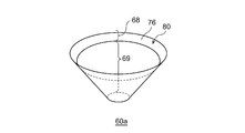
- FIG. 3 is a schematic perspective view of another exemplary cryopanel that can be used in the cryopump 10 shown in FIG.
- the cryopanel shown is a cryopanel that can be used for the second-stage cryopanel assembly 20, and is the upper cryopanel 60a.
- the illustrated cryopanel may be another suction cryopanel 60 used for the second-stage cryopanel assembly 20.
- the upper cryopanel 60a has, for example, an inverted conical shape, as described with reference to FIG.
- the front surface of the upper cryopanel 60a has an exposed region 68 on the outer periphery and a non-exposed region 69 inside the exposed region 68.
- An adsorbent may be provided in the non-exposed area 69, but is omitted in FIG. 3 for simplicity of illustration.
- the upper cryopanel 60 a (or the adsorbed cryopanel 60) includes a protective layer 80 covering the exposed area 68 to provide a removable protective surface 76.
- the protection layer 80 is not provided in the non-exposed region 69.
- the surface of the protective layer 80 functioning as the protective surface 76 is made of a material having corrosion resistance to a difficult-to-reproduce gas, for example, a fluororesin such as polytetrafluoroethylene or another resin, or a metal such as aluminum or copper. It may be formed. Therefore, the protective layer 80 may be a pressure-sensitive adhesive tape having a surface of such a resin material or a metal material, or a protective film adhered releasably. The protective layer 80 is adhered to the cryopanel substrate of the upper cryopanel 60a, thereby being thermally bonded and cooled to the same cooling temperature.
- the protective layer 80 Since the protective layer 80 is provided in the exposed region 68 and is cooled to the second cooling temperature, the hard-to-regenerate gas may condense on the protective surface 76 and become contaminated. Since the protective layer 80 is detachably adhered to the upper cryopanel 60a, contaminants can be removed from the upper cryopanel 60a by peeling the protective layer 80 during maintenance of the cryopump 10. The upper cryopanel 60a can be reused without performing complicated operations such as disassembly and cleaning during maintenance.
- FIG. 4 is a schematic top view of yet another exemplary cryopanel that can be used in the cryopump 10 shown in FIG.
- the cryopanel shown is a cryopanel that can be used for the second-stage cryopanel assembly 20, and is a lower cryopanel 60b.
- the illustrated cryopanel may be another suction cryopanel 60 used for the second-stage cryopanel assembly 20.
- the lower cryopanel 60b has, for example, a disk shape as described with reference to FIG. However, the lower cryopanel 60b is formed with a cutout 82 from a part of the outer periphery to the center for attachment to the second cryopanel attachment member 64.
- the front surface of the lower cryopanel 60b has an exposed region 68 on the outer periphery and a non-exposed region 69 inside the exposed region 68.
- a granular activated carbon 84 as an adsorbent is attached to the non-exposed area 69.
- the lower cryopanel 60b (or the adsorbed cryopanel 60) includes a resin or metal protective layer 80 releasably bonded to the exposed area 68 to provide a removable protective surface 76.
- the protective layer 80 is adhered to the cryopanel substrate of the lower cryopanel 60b, thereby being thermally bonded and cooled to the same cooling temperature.
- the protective layer 80 Since the protective layer 80 is provided in the exposed region 68 and is cooled to the second cooling temperature, the hard-to-regenerate gas may condense on the protective surface 76 and become contaminated. Since the protective layer 80 is detachably adhered to the lower cryopanel 60b, by removing the protective layer 80 during maintenance of the cryopump 10, contaminants can be removed from the lower cryopanel 60b. The lower cryopanel 60b can be reused without performing complicated operations such as disassembly and cleaning during maintenance.
- a new protective layer 80 may or may not be attached to the adsorption cryopanel 60. Whether or not to attach a new protective layer 80 may be determined in consideration of the cost of the protective layer 80 and the life of the adsorbent on the adsorption cryopanel 60.
- a plurality of protective layers 80 may be stacked on the exposed region 68. In this way, when the used protective layer 80 is peeled off, a new protective layer 80 immediately below the used protective layer 80 is exposed and becomes usable.
- the inside of the vacuum chamber is first roughly evacuated to about 1 Pa by another appropriate roughing pump before the operation. Thereafter, the cryopump 10 is operated.
- the first cooling stage 22 and the second cooling stage 24 are cooled to the first cooling temperature and the second cooling temperature, respectively. Accordingly, the first-stage cryopanel 18 and the second-stage cryopanel assembly 20 that are thermally coupled to these are also cooled to the first cooling temperature and the second cooling temperature, respectively.
- the inlet cryopanel 32 cools gas flowing from the vacuum chamber toward the cryopump 10.
- a gas having a sufficiently low vapor pressure for example, 10 ⁇ 8 Pa or less
- This gas may be referred to as a first type gas.
- the first type gas is, for example, water vapor.
- the inlet cryopanel 32 can exhaust the first type gas. Part of the gas whose vapor pressure is not sufficiently low at the first cooling temperature enters the internal space 14 from the intake port 12. Alternatively, another part of the gas is reflected by the entrance cryopanel 32 and does not enter the internal space 14.
- the gas that has entered the internal space 14 is cooled by the second-stage cryopanel assembly 20.
- a gas having a sufficiently low vapor pressure for example, 10 ⁇ 8 Pa or less
- This gas may be referred to as a second type gas.
- the second type gas is, for example, nitrogen (N 2 ) or argon (Ar).
- the second stage cryopanel assembly 20 can exhaust the second type gas.
- the gas whose vapor pressure is not sufficiently low at the second cooling temperature is adsorbed on the adsorption area 66 of the adsorption cryopanel 60.
- This gas may be referred to as a third type gas.
- the third type gas is, for example, hydrogen (H 2 ).
- the second stage cryopanel assembly 20 can exhaust the third type gas. Therefore, the cryopump 10 can exhaust various gases by condensing or adsorbing, and reach a desired degree of vacuum in the vacuum chamber.
- the exposed region 68 is covered with the removable protective surface 76. Since it is cooled to the second cooling temperature similarly to the second-stage cryopanel assembly 20, the hard-to-regenerate gas is condensed on the protection surface 76. Although the hard-to-regenerate gas can adhere to the protection surface 76 and become contaminated, the protection surface 76 can be removed. By removing the protective surface 76, the clean surface covered by the protective surface 76 is exposed. Alternatively, the exposed area 68 is again protected by attaching a new protective surface 76. Therefore, the cryopump 10 does not need to disassemble and clean the second-stage cryopanel assembly 20 to remove deposits such as difficult-to-regenerate gas during maintenance. Maintenance of the cryopump 10 can be performed more easily than a cryopump without such a removable protection surface 76.
- the cryopump 10 is an adsorbent non-exposed type, and since the adsorption region 66 is disposed in the non-exposed region 69, the adsorption region 66 is protected from the difficult-to-regenerate gas. Therefore, if the hard-to-regenerate gas is removed by removing or replacing the protection surface 76, the second-stage cryopanel assembly 20 can be reused. Thus, when the cryopump 10 is of the non-exposed type, the maintenance of the cryopump 10 can be easily performed.
- the case where the protective layer 80 is not provided in the non-exposed region 69 has been described as an example, but this is not essential to the present invention.
- at least a portion of the non-exposed region 69 eg, a portion of the non-exposed region 69 outside the suction region 66
- the protective layer 80 may be releasably adhered to an area where an adsorbent such as activated carbon is not attached.
- the present invention is also applicable to other vertical cryopumps.
- the vertical cryopump refers to a cryopump in which the refrigerator 16 is disposed along the central axis C of the cryopump 10.
- the internal configuration of the cryopump such as the arrangement, shape, and number of cryopanels, is not limited to the specific embodiment described above. Various known configurations can be appropriately adopted.
- the present invention can be used in the fields of cryopumps and cryopanels.
- cryopump ⁇ 10 ⁇ cryopump, ⁇ 12 ⁇ intake, ⁇ 66 ⁇ adsorption area, ⁇ 68 ⁇ exposed area, ⁇ 69 ⁇ non-exposed area, ⁇ 76 ⁇ protective surface, ⁇ 78a, 78b ⁇ cryopanel substrate, ⁇ 80 ⁇ protective layer.
Landscapes
- Engineering & Computer Science (AREA)
- Mechanical Engineering (AREA)
- General Engineering & Computer Science (AREA)
- Compressors, Vaccum Pumps And Other Relevant Systems (AREA)
Abstract
Description
Claims (11)
- クライオポンプ吸気口を通じて被排気気体が直線的に到達可能な露出領域と、前記クライオポンプ吸気口を通じて被排気気体が直線的に到達不能な非露出領域と、を備えるクライオパネルアセンブリを備え、
前記非露出領域は、非凝縮性気体を吸着可能な吸着領域を有し、前記露出領域は、取り外し可能な保護面で被覆されていることを特徴とするクライオポンプ。 - 前記取り外し可能な保護面を提供するように前記露出領域に剥離可能に接着された樹脂製または金属製の保護層をさらに備えることを特徴とする請求項1に記載のクライオポンプ。
- 前記露出領域には複数の保護層が積層されていることを特徴とする請求項1または2に記載のクライオポンプ。
- 前記クライオパネルアセンブリは、前記非凝縮性気体を吸着不能とする第1のクライオパネル基材と、前記非凝縮性気体を吸着不能とする第2のクライオパネル基材と、を備え、
前記第2のクライオパネル基材が、前記取り外し可能な保護面を提供するように前記第1のクライオパネル基材に取り外し可能に装着されていることを特徴とする請求項1から3のいずれかに記載のクライオポンプ。 - 前記非露出領域の少なくとも一部が前記取り外し可能な保護面で被覆されていることを特徴とする請求項1から4のいずれかに記載のクライオポンプ。
- 前記クライオポンプ吸気口から軸方向に筒状に延在し、前記クライオパネルアセンブリを囲むように配置された放射シールドと、
前記放射シールドを冷却する高温冷却ステージと、前記クライオパネルアセンブリを冷却する低温冷却ステージとを備え、前記低温冷却ステージが前記高温冷却ステージよりも低温に冷却される冷凍機と、をさらに備えることを特徴とする請求項1から5のいずれかに記載のクライオポンプ。 - 前記クライオパネルアセンブリは、各々が前記露出領域および前記非露出領域を有する複数のクライオパネルと、軸方向に柱状に配列された複数の伝熱体と、を備え、前記複数のクライオパネルおよび前記複数の伝熱体が軸方向に積み重ねられていることを特徴とする請求項6に記載のクライオポンプ。
- 前記クライオパネルアセンブリは、前記クライオパネルアセンブリのうち軸方向に最も上方に配置されたトップクライオパネルを備え、
前記トップクライオパネルは、第1のクライオパネル基材と、前記取り外し可能な保護面を提供する第2のクライオパネル基材とを備え、前記第2のクライオパネル基材は、その裏面が前記第1のクライオパネル基材の前面と接触し、前記第1のクライオパネル基材の前面の全体を覆うようにして、前記第1のクライオパネル基材に取り外し可能に装着されていることを特徴とする請求項6または7に記載のクライオポンプ。 - 前記クライオパネルアセンブリは、前記低温冷却ステージよりも軸方向上方に配置され、逆円錐状の外周部を有する少なくとも1つの上部クライオパネルを備え、前記取り外し可能な保護面で被覆された前記露出領域は、前記逆円錐状の外周部に設けられていることを特徴とする請求項6から8のいずれかに記載のクライオポンプ。
- 前記クライオパネルアセンブリは、前記低温冷却ステージよりも軸方向下方に配置された少なくとも1つの下部クライオパネルを備え、前記取り外し可能な保護面で被覆された前記露出領域は、前記少なくとも1つの下部クライオパネルの外周部に設けられていることを特徴とする請求項6から9のいずれかに記載のクライオポンプ。
- クライオパネル基材と、前記クライオパネル基材の少なくとも一部を被覆する取り外し可能な保護面と、を備えることを特徴とするクライオパネル。
Priority Applications (4)
| Application Number | Priority Date | Filing Date | Title |
|---|---|---|---|
| CN201980055451.6A CN112601888B (zh) | 2018-09-06 | 2019-08-01 | 低温泵及低温板 |
| KR1020217005153A KR102597866B1 (ko) | 2018-09-06 | 2019-08-01 | 크라이오펌프 및 크라이오패널 |
| JP2020541069A JP7311522B2 (ja) | 2018-09-06 | 2019-08-01 | クライオポンプ |
| US17/193,682 US20210190057A1 (en) | 2018-09-06 | 2021-03-05 | Cryopump and cryopanel |
Applications Claiming Priority (2)
| Application Number | Priority Date | Filing Date | Title |
|---|---|---|---|
| JP2018-167177 | 2018-09-06 | ||
| JP2018167177 | 2018-09-06 |
Related Child Applications (1)
| Application Number | Title | Priority Date | Filing Date |
|---|---|---|---|
| US17/193,682 Continuation US20210190057A1 (en) | 2018-09-06 | 2021-03-05 | Cryopump and cryopanel |
Publications (1)
| Publication Number | Publication Date |
|---|---|
| WO2020049916A1 true WO2020049916A1 (ja) | 2020-03-12 |
Family
ID=69722430
Family Applications (1)
| Application Number | Title | Priority Date | Filing Date |
|---|---|---|---|
| PCT/JP2019/030302 Ceased WO2020049916A1 (ja) | 2018-09-06 | 2019-08-01 | クライオポンプおよびクライオパネル |
Country Status (6)
| Country | Link |
|---|---|
| US (1) | US20210190057A1 (ja) |
| JP (1) | JP7311522B2 (ja) |
| KR (1) | KR102597866B1 (ja) |
| CN (1) | CN112601888B (ja) |
| TW (1) | TWI712738B (ja) |
| WO (1) | WO2020049916A1 (ja) |
Citations (5)
| Publication number | Priority date | Publication date | Assignee | Title |
|---|---|---|---|---|
| JPH0718410B2 (ja) * | 1987-10-01 | 1995-03-06 | 日電アネルバ株式会社 | クライオポンプ |
| JP2512129B2 (ja) * | 1989-01-20 | 1996-07-03 | 株式会社日立製作所 | クライオポンプ |
| JP2010516939A (ja) * | 2007-01-17 | 2010-05-20 | ブルックス オートメーション インコーポレイテッド | 圧力バーストが生じない大容量クライオポンプ |
| JP2012237263A (ja) * | 2011-05-12 | 2012-12-06 | Sumitomo Heavy Ind Ltd | クライオポンプ及びその製造方法 |
| JP2018127943A (ja) * | 2017-02-08 | 2018-08-16 | 住友重機械工業株式会社 | クライオポンプ |
Family Cites Families (11)
| Publication number | Priority date | Publication date | Assignee | Title |
|---|---|---|---|---|
| JP3571460B2 (ja) * | 1996-05-30 | 2004-09-29 | 日東電工株式会社 | 再剥離型感圧接着シ―ト類 |
| JPH10184540A (ja) | 1996-12-25 | 1998-07-14 | Anelva Corp | クライオポンプ |
| WO2006102581A1 (en) * | 2005-03-24 | 2006-09-28 | 3M Innovative Properties Company | Corrosion resistant metallized films and methods of making the same |
| US20080138558A1 (en) * | 2006-12-07 | 2008-06-12 | Sassan Hojabr | Peelable multilayer surface protecting film and articles thereof |
| JP6045056B2 (ja) * | 2010-11-30 | 2016-12-14 | 日東電工株式会社 | 表面保護シート |
| JP5557786B2 (ja) * | 2011-04-05 | 2014-07-23 | 住友重機械工業株式会社 | クライオポンプのための蓋構造、クライオポンプ、クライオポンプの立ち上げ方法、及びクライオポンプの保管方法 |
| WO2014119750A1 (ja) * | 2013-01-31 | 2014-08-07 | コニカミノルタ株式会社 | ガスバリア性フィルム |
| JP6053588B2 (ja) * | 2013-03-19 | 2016-12-27 | 住友重機械工業株式会社 | クライオポンプ、及び非凝縮性気体の真空排気方法 |
| CN106014917B (zh) * | 2015-03-31 | 2018-07-17 | 住友重机械工业株式会社 | 低温泵 |
| CN106704145B (zh) * | 2016-11-30 | 2019-02-19 | 上海华力微电子有限公司 | 一种具有再生功能的低温泵系统 |
| JP6871751B2 (ja) * | 2017-02-07 | 2021-05-12 | 住友重機械工業株式会社 | クライオポンプ |
-
2019
- 2019-08-01 WO PCT/JP2019/030302 patent/WO2020049916A1/ja not_active Ceased
- 2019-08-01 CN CN201980055451.6A patent/CN112601888B/zh active Active
- 2019-08-01 KR KR1020217005153A patent/KR102597866B1/ko active Active
- 2019-08-01 JP JP2020541069A patent/JP7311522B2/ja active Active
- 2019-08-30 TW TW108131179A patent/TWI712738B/zh active
-
2021
- 2021-03-05 US US17/193,682 patent/US20210190057A1/en not_active Abandoned
Patent Citations (5)
| Publication number | Priority date | Publication date | Assignee | Title |
|---|---|---|---|---|
| JPH0718410B2 (ja) * | 1987-10-01 | 1995-03-06 | 日電アネルバ株式会社 | クライオポンプ |
| JP2512129B2 (ja) * | 1989-01-20 | 1996-07-03 | 株式会社日立製作所 | クライオポンプ |
| JP2010516939A (ja) * | 2007-01-17 | 2010-05-20 | ブルックス オートメーション インコーポレイテッド | 圧力バーストが生じない大容量クライオポンプ |
| JP2012237263A (ja) * | 2011-05-12 | 2012-12-06 | Sumitomo Heavy Ind Ltd | クライオポンプ及びその製造方法 |
| JP2018127943A (ja) * | 2017-02-08 | 2018-08-16 | 住友重機械工業株式会社 | クライオポンプ |
Also Published As
| Publication number | Publication date |
|---|---|
| JP7311522B2 (ja) | 2023-07-19 |
| KR102597866B1 (ko) | 2023-11-02 |
| TW202010940A (zh) | 2020-03-16 |
| TWI712738B (zh) | 2020-12-11 |
| KR20210044228A (ko) | 2021-04-22 |
| JPWO2020049916A1 (ja) | 2021-08-12 |
| US20210190057A1 (en) | 2021-06-24 |
| CN112601888A (zh) | 2021-04-02 |
| CN112601888B (zh) | 2022-09-23 |
Similar Documents
| Publication | Publication Date | Title |
|---|---|---|
| JP5460644B2 (ja) | クライオポンプ | |
| JP5398780B2 (ja) | クライオポンプ | |
| JP6053588B2 (ja) | クライオポンプ、及び非凝縮性気体の真空排気方法 | |
| EP3710699B1 (en) | Cryopump with enhanced frontal array | |
| US20200400365A1 (en) | Cryopump | |
| TWI750505B (zh) | 低溫泵 | |
| US20190360477A1 (en) | Cryopump | |
| CN112601888B (zh) | 低温泵及低温板 | |
| JP6857046B2 (ja) | クライオポンプ | |
| CN110234878B (zh) | 低温泵 | |
| JP5669893B2 (ja) | クライオポンプ及びその製造方法 | |
| JP5669895B2 (ja) | クライオポンプ及びその製造方法 | |
| CN121002282A (zh) | 低温泵 |
Legal Events
| Date | Code | Title | Description |
|---|---|---|---|
| 121 | Ep: the epo has been informed by wipo that ep was designated in this application |
Ref document number: 19858489 Country of ref document: EP Kind code of ref document: A1 |
|
| ENP | Entry into the national phase |
Ref document number: 2020541069 Country of ref document: JP Kind code of ref document: A |
|
| ENP | Entry into the national phase |
Ref document number: 20217005153 Country of ref document: KR Kind code of ref document: A |
|
| NENP | Non-entry into the national phase |
Ref country code: DE |
|
| 122 | Ep: pct application non-entry in european phase |
Ref document number: 19858489 Country of ref document: EP Kind code of ref document: A1 |