WO2020045600A1 - 熱音響装置 - Google Patents
熱音響装置 Download PDFInfo
- Publication number
- WO2020045600A1 WO2020045600A1 PCT/JP2019/034025 JP2019034025W WO2020045600A1 WO 2020045600 A1 WO2020045600 A1 WO 2020045600A1 JP 2019034025 W JP2019034025 W JP 2019034025W WO 2020045600 A1 WO2020045600 A1 WO 2020045600A1
- Authority
- WO
- WIPO (PCT)
- Prior art keywords
- temperature
- gas
- waveguide
- heat exchanger
- sound wave
- Prior art date
- Legal status (The legal status is an assumption and is not a legal conclusion. Google has not performed a legal analysis and makes no representation as to the accuracy of the status listed.)
- Ceased
Links
Images




Classifications
-
- F—MECHANICAL ENGINEERING; LIGHTING; HEATING; WEAPONS; BLASTING
- F03—MACHINES OR ENGINES FOR LIQUIDS; WIND, SPRING, OR WEIGHT MOTORS; PRODUCING MECHANICAL POWER OR A REACTIVE PROPULSIVE THRUST, NOT OTHERWISE PROVIDED FOR
- F03G—SPRING, WEIGHT, INERTIA OR LIKE MOTORS; MECHANICAL-POWER PRODUCING DEVICES OR MECHANISMS, NOT OTHERWISE PROVIDED FOR OR USING ENERGY SOURCES NOT OTHERWISE PROVIDED FOR
- F03G7/00—Mechanical-power-producing mechanisms, not otherwise provided for or using energy sources not otherwise provided for
- F03G7/025—Mechanical-power-producing mechanisms, not otherwise provided for or using energy sources not otherwise provided for characterised by its use
- F03G7/0252—Motors; Energy harvesting or waste energy recovery
-
- F—MECHANICAL ENGINEERING; LIGHTING; HEATING; WEAPONS; BLASTING
- F03—MACHINES OR ENGINES FOR LIQUIDS; WIND, SPRING, OR WEIGHT MOTORS; PRODUCING MECHANICAL POWER OR A REACTIVE PROPULSIVE THRUST, NOT OTHERWISE PROVIDED FOR
- F03G—SPRING, WEIGHT, INERTIA OR LIKE MOTORS; MECHANICAL-POWER PRODUCING DEVICES OR MECHANISMS, NOT OTHERWISE PROVIDED FOR OR USING ENERGY SOURCES NOT OTHERWISE PROVIDED FOR
- F03G7/00—Mechanical-power-producing mechanisms, not otherwise provided for or using energy sources not otherwise provided for
- F03G7/008—Mechanical-power-producing mechanisms, not otherwise provided for or using energy sources not otherwise provided for characterised by the actuating element
-
- F—MECHANICAL ENGINEERING; LIGHTING; HEATING; WEAPONS; BLASTING
- F03—MACHINES OR ENGINES FOR LIQUIDS; WIND, SPRING, OR WEIGHT MOTORS; PRODUCING MECHANICAL POWER OR A REACTIVE PROPULSIVE THRUST, NOT OTHERWISE PROVIDED FOR
- F03G—SPRING, WEIGHT, INERTIA OR LIKE MOTORS; MECHANICAL-POWER PRODUCING DEVICES OR MECHANISMS, NOT OTHERWISE PROVIDED FOR OR USING ENERGY SOURCES NOT OTHERWISE PROVIDED FOR
- F03G7/00—Mechanical-power-producing mechanisms, not otherwise provided for or using energy sources not otherwise provided for
- F03G7/029—Mechanical-power-producing mechanisms, not otherwise provided for or using energy sources not otherwise provided for characterised by the material or the manufacturing process, e.g. the assembly
-
- F—MECHANICAL ENGINEERING; LIGHTING; HEATING; WEAPONS; BLASTING
- F25—REFRIGERATION OR COOLING; COMBINED HEATING AND REFRIGERATION SYSTEMS; HEAT PUMP SYSTEMS; MANUFACTURE OR STORAGE OF ICE; LIQUEFACTION SOLIDIFICATION OF GASES
- F25B—REFRIGERATION MACHINES, PLANTS OR SYSTEMS; COMBINED HEATING AND REFRIGERATION SYSTEMS; HEAT PUMP SYSTEMS
- F25B9/00—Compression machines, plants or systems, in which the refrigerant is air or other gas of low boiling point
-
- H—ELECTRICITY
- H04—ELECTRIC COMMUNICATION TECHNIQUE
- H04R—LOUDSPEAKERS, MICROPHONES, GRAMOPHONE PICK-UPS OR LIKE ACOUSTIC ELECTROMECHANICAL TRANSDUCERS; ELECTRIC HEARING AIDS; PUBLIC ADDRESS SYSTEMS
- H04R23/00—Transducers other than those covered by groups H04R9/00 - H04R21/00
Definitions
- thermoacoustic device relate to a thermoacoustic device.
- thermoacoustic device that converts heat energy into acoustic energy by a thermoacoustic effect, which is an interaction between heat and sound waves, and converts acoustic energy into other energy such as electric energy is known.
- thermoacoustic generator in which a generator that generates power in response to the generator is provided in a loop tube is disclosed (for example, see Patent Document 1).
- the thermoacoustic apparatus includes a loop-shaped waveguide and a heat exchanger.
- the loop waveguide is filled with a medium.
- the heat exchanger is provided in the waveguide and has a low temperature section and a high temperature section.
- the phase velocity of the sound wave generated and amplified in the medium by the temperature gradient generated between the low temperature part and the high temperature part corresponds to the temperature rise or temperature decrease rate of the medium caused by the temperature gradient.
- FIG. 1 is a diagram illustrating an example of the thermoacoustic device according to the embodiment.
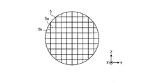
- FIG. 2 is a diagram illustrating an example of a high-temperature portion of the heat exchanger included in the thermoacoustic apparatus according to the embodiment.
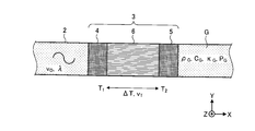
- FIG. 3 is a diagram illustrating an example of a temperature gradient holding unit of the heat exchanger included in the thermoacoustic apparatus according to the embodiment.
- FIG. 4A is a diagram illustrating a physical quantity related to a relational expression between a phase velocity of a sound wave and a heating or cooling rate of a gas in the thermoacoustic apparatus according to the embodiment.
- FIG. 1 is a diagram illustrating an example of the thermoacoustic device according to the embodiment.
- FIG. 2 is a diagram illustrating an example of a high-temperature portion of the heat exchanger included in the thermoacoustic apparatus according to the embodiment.
- FIG. 3 is a diagram illustrating an example of a temperature gradient holding unit of the heat exchanger included in the
- FIG. 4B is a diagram illustrating a physical quantity related to a relational expression between a phase velocity of a sound wave and a heating or cooling rate of a gas in the thermoacoustic apparatus according to the embodiment.
- FIG. 5 is a diagram illustrating physical quantities related to a relational expression between the quantity of heat transmitted to the gas and the quantity of heat transmitted to the plurality of fins in the thermoacoustic apparatus according to the embodiment.
- thermoacoustic apparatus disclosed in the present application
- FIG. 1 is a diagram illustrating an example of the thermoacoustic device 1 according to the embodiment.
- the near side in the direction orthogonal to the paper surface is the positive direction of the Z-axis direction
- the longitudinal direction and the lateral direction of the thermoacoustic device 1 are the X-axis direction and the Y-axis direction, respectively. 1 shows a three-dimensional rectangular coordinate system.
- the thermoacoustic device 1 is a device that converts heat energy into acoustic energy of sound waves and converts acoustic energy of sound waves into other energy such as electric energy by a thermoacoustic effect.
- the thermoacoustic effect is an interaction between heat and sound waves.
- the thermoacoustic device 1 according to the embodiment includes a waveguide 2, a heat exchanger 3, an exciter 7, and a converter 8.
- the waveguide 2 is filled with a gas G.
- the gas G is, for example, air, nitrogen (N 2 ), helium (He), argon (Ar), hydrogen (H 2 ), carbon dioxide (CO 2 ), or the like.
- the waveguide 2 seals the gas G inside.
- the pressure of the gas G filled in the waveguide 2 is, for example, not less than 1 atm (1013.25 hPa) and less than 10 atm (10132.5 hPa).
- the waveguide 2 is a loop-shaped waveguide having no reflective wall.
- the waveguide 2 has, for example, a single loop shape as shown in FIG.
- the waveguide 2 resonates sound waves generated in the gas G.
- the phase of the temperature change of the gas G caused by the heat conduction between the heat exchanger 3 and the gas G with respect to the movement (advance) of the gas G by the sound wave generated in the gas G is caused by the rise of the medium. Delay by an amount corresponding to the warming or cooling rate. Accordingly, the phase of the pressure change of the sound wave of the gas G is delayed by 0 ° to 90 ° from the phase of the pressure change of the gas G when there is no temperature change.
- thermoacoustic device 1 when the waveguide 2 has a reflecting wall, the resonance of the sound wave caused by the temperature change generated in the gas G is not stabilized, and the amplitude of the sound wave generated in the gas G is reduced.
- the resonance of the sound wave generated in the gas G can be stabilized by the waveguide 2 having the shape of the loop without the reflective wall. Accordingly, the thermoacoustic device 1 according to the embodiment can increase the output of acoustic energy of sound waves.
- the length of the waveguide 2 is an integral multiple of the wavelength of the sound wave generated in the gas G.
- the length of the waveguide 2 is set so that, for example, the resonance frequency of the sound wave generated in the gas G is 1 m or less.
- the waveguide 2 is, for example, a hollow waveguide having a circular or square cross section.
- the waveguide 2 is formed of, for example, a metal such as stainless steel (SUS) or a plastic such as vinyl chloride.
- SUS stainless steel
- plastic such as vinyl chloride.
- the heat exchanger 3 transfers heat to the gas G filled in the waveguide 2.
- the heat exchanger 3 heats / cools the gas G according to the phase of the advection of the sound wave.
- the length of the heat exchanger 3 in the direction in which the waveguide 2 extends (X-axis direction) is, for example, about 1/20 of the wavelength of the sound wave generated in the gas G, for example, about 5 cm.
- the heat exchanger 3 is provided in the waveguide 2.
- the heat exchanger 3 has a low temperature section 4, a high temperature section 5, and a temperature gradient holding section 6.
- the low temperature section 4 is a member included in the heat exchanger 3 that maintains a relatively low temperature.
- the high temperature section 5 is a member included in the heat exchanger 3 that maintains a relatively high temperature.
- the relatively low temperature and the relatively high temperature are based on a comparison between the temperature of the low temperature section 4 and the temperature of the high temperature section 5. That is, the temperature of the high temperature part 5 is higher than the temperature of the low temperature part 4.
- a temperature gradient occurs between the low temperature section 4 and the high temperature section 5. The configurations of the low temperature section 4 and the high temperature section 5 will be described later.
- the low temperature section 4 and the high temperature section 5 are connected to a relatively low temperature heat source and a relatively high temperature heat source, respectively.
- the relatively low temperature heat source may be, for example, a coolant such as water supplied to the tube.
- the relatively high temperature heat source may be a heating medium such as boiling water supplied to the tube.
- One of the relatively low temperature heat source and the relatively high temperature heat source may be, for example, air at room temperature.
- the temperature gradient holding section 6 is a member that holds a temperature gradient generated between the low temperature section 4 and the high temperature section 5 of the heat exchanger 3.
- the temperature gradient holding section 6 is provided between the low temperature section 4 and the high temperature section 5 of the heat exchanger 3.
- the distance between the low-temperature section 4 and the temperature gradient holding section 6 and the distance between the temperature gradient holding section 6 and the high-temperature section 5 are, for example, 0.3 mm or less.
- the temperature gradient holding unit 6 generates and amplifies a sound wave in the gas G by a temperature gradient generated between the low temperature unit 4 and the high temperature unit 5. The configuration of the temperature gradient holding unit 6 will be described later.
- the exciter 7 generates a sound wave in the gas G at a predetermined frequency.
- the exciter 7 is provided in the waveguide 2 so as to seal the gas G.
- the piston inserted into a cylinder provided so as not to change the acoustic impedance of the waveguide 2 reciprocates, whereby the pressure of the gas G is increased. Vibrates.
- the converter 8 converts acoustic energy of sound waves generated in the gas G into predetermined energy and extracts predetermined energy.
- the converter 8 may be, for example, a generator that generates electricity by converting acoustic energy of sound waves generated in the gas G into electric energy.
- the thermoacoustic device 1 can generate power using, for example, heat supplied to the heat exchanger 3 from a heat source.
- the converter 8 is, for example, a cooler (cooling heat exchanger) that lowers the temperature of a medium that contacts the converter 8 by converting acoustic energy of sound waves generated in the gas G into heat energy for cooling.
- the thermoacoustic device 1 can cool the medium using, for example, heat supplied to the heat exchanger 3 from a heat source.
- the gas G filled in the waveguide 2 is vibrated at a predetermined frequency by the exciter 7.
- the gas G moves from the low temperature side to the high temperature side of the temperature gradient holding unit 6 in the heat exchanger 3.
- the gas G expands by being heated by the temperature gradient held by the temperature gradient holding unit 6.
- the gas G moves from the high temperature side to the low temperature side of the temperature gradient holding unit 6 in the heat exchanger 3.
- the gas G is cooled and contracted by the temperature gradient held by the temperature gradient holding unit 6.
- the sound wave of the gas G filled in the waveguide 2 is amplified by the repetition of expansion and contraction of the gas G in the heat exchanger 3, and the heat energy is converted into the acoustic energy of the sound wave of the gas G.
- the sound wave generated in the gas G filled in the waveguide 2 by the exciter 7 can be excited at a predetermined frequency. Sound waves generated in the gas G are stabilized by resonating in the waveguide 2. When the sound wave generated in the gas G reaches the converter 8, the converter 8 can convert the acoustic energy of the sound wave generated in the gas G into predetermined energy and extract the predetermined energy.
- FIG. 2 is a diagram illustrating an example of the high-temperature section 5 of the heat exchanger 3 included in the thermoacoustic apparatus 1 according to the embodiment.
- the high temperature part 5 of the heat exchanger 3 has, for example, a substantially cylindrical shape.
- the thickness of the high-temperature portion 5 of the heat exchanger 3 in the direction of the central axis (X-axis direction) is, for example, 1 cm or more and 2 cm or less.
- the high temperature part 5 of the heat exchanger 3 has, for example, a plurality of fins 5a and 5b that are orthogonal to the direction of the central axis (X-axis direction) and orthogonal to each other. That is, the high temperature section 5 of the heat exchanger 3 has lattice-shaped fins 5a and 5b.
- the plurality of fins 5a and 5b are formed of, for example, metal. In this case, the thermal conductivity of the plurality of fins 5a, 5b can be improved.
- the metal forming the plurality of fins 5a and 5b is, for example, copper. In this case, the cost of the plurality of fins 5a and 5b can be reduced.
- the thickness of the plurality of fins 5a, 5b is, for example, 100 ⁇ m or less.
- the interval between the plurality of fins 5a, 5b is, for example, 0.4 mm or more and 1.5 mm or less.
- the low temperature part 4 of the heat exchanger 3 has the same or similar structure as the structure of the high temperature part 5 of the heat exchanger 3.
- FIG. 3 is a diagram illustrating an example of the temperature gradient holding unit 6 of the heat exchanger 3 included in the thermoacoustic apparatus 1 according to the embodiment.
- the temperature gradient holding unit 6 of the heat exchanger 3 has, for example, a substantially cylindrical shape.
- the length of the temperature gradient holding section 6 of the heat exchanger 3 in the direction of the central axis (X-axis direction) is, for example, 1 cm or more and 2 cm or less. In this case, by obtaining the effective amplitude of the sound wave, an effective output of the sound energy of the sound wave converted from the heat energy of the temperature gradient holding unit 6 can be obtained.
- the temperature gradient holding unit 6 of the heat exchanger 3 has, for example, a plurality of fins 6a that are orthogonal to the direction of the central axis (X-axis direction) and are parallel to each other.
- the temperature gradient holding unit 6 of the heat exchanger 3 has, for example, a plurality of partitions 6b provided between a plurality of fins 6a.
- the plurality of fins 6a and the plurality of partitions 6b are formed of, for example, ceramic or glass having low thermal conductivity. In this case, the thermal conductivity of the plurality of fins 6a and the plurality of partitions 6b can be reduced. Therefore, reduction of the temperature gradient in the temperature gradient holding unit 6 of the heat exchanger 3 can be reduced. Accordingly, the temperature gradient holding section 6 can satisfactorily hold the temperature gradient generated between the low temperature section 4 and the high temperature section 5 of the heat exchanger 3.
- the ceramic forming the plurality of fins 6a and the plurality of partitions 6b is, for example, zirconia, titania, or steatite.
- the thermal conductivity of the plurality of fins 6a and the plurality of partitions 6b can be satisfactorily reduced with respect to the thermal conductivity of the gas G from the plurality of fins 6a and the plurality of partitions 6b. Therefore, the temperature gradient holding unit 6 can enhance heat conduction from the plurality of fins 6a and the plurality of partitions 6b to the gas G. Accordingly, the temperature gradient holding section 6 can easily hold a desired temperature gradient between the low temperature section 4 and the high temperature section 5 of the heat exchanger 3.
- the thickness of the plurality of fins 6a is, for example, 100 ⁇ m or less. Distance d F between the plurality of fins 6a as shown in FIG. 3, for example, at 0.4mm or 1.5mm or less. The thickness of the partitions 6b and the intervals between the partitions 6b are determined as appropriate. When the material of the plurality of partitions 6b is the same as the plurality of fins 6a, they may be integrally shaped and manufactured.
- FIGS. 4A and 4B are diagrams illustrating physical quantities relating to a relational expression between the phase velocity of a sound wave and the rate of temperature rise or fall of the gas G in the thermoacoustic apparatus 1 according to the embodiment.
- the density of the filled gas G in the waveguide 2 represented by [rho G, C G, kappa G, and P G.
- the phase velocity and wavelength of the sound wave generated in the gas G are represented by v 0 and ⁇ , respectively.
- T 1 and T 2 satisfy the relationship of T 2 > T 1 .
- the temperature difference held by the temperature gradient holding unit 6 of the heat exchanger 3 is represented by ⁇ T.
- the heating or cooling rate of the gas G in the temperature gradient holder 6 of the heat exchanger 3 represented by v T. Note that the temperature gradient can be obtained by dividing the temperature difference ⁇ T by the length of the temperature gradient holding unit 6 in the X-axis direction.
- thermoacoustic apparatus 1 the phase velocity v 0 of the sound wave generated in the gas G by the temperature difference ⁇ T generated between the low temperature part 4 and the high temperature part 5 of the heat exchanger 3 is generated by the temperature difference ⁇ T. corresponding to heating or cooling rate v T of the gas G.
- the sound wave phase speed v 0 is a speed at which a specific position of the sound wave such as a peak or a valley of the sound wave moves.
- the rate of temperature rise or fall v T of the gas G is determined by the temperature difference ⁇ T generated between the low-temperature part 4 and the high-temperature part 5 of the heat exchanger 3, when the gas G is heated or expanded or cooled and contracted. Or the rate at which the temperature drops.
- thermoacoustic apparatus 1 since the phase velocity v 0 of the sound wave generated in the gas G corresponds to the temperature increase or decrease rate v T of the gas G, the gas caused by the movement of the gas G and the temperature difference ⁇ T G can be better synchronized with the thermal expansion or cooling contraction.
- the temperature of the gas G can be increased or decreased efficiently. That is, it is possible to increase the efficiency of adjusting the heat conduction between the heat exchanger 3 and the gas G to the timing of the advection of the sound waves. Accordingly, the thermoacoustic device 1 according to the embodiment can increase the efficiency of converting thermal energy into acoustic energy of sound waves.
- the efficiency of converting heat energy into acoustic energy of sound waves was sometimes low.
- the efficiency of converting heat energy into acoustic energy of sound waves may decrease.
- the efficiency of converting heat energy into acoustic energy of sound waves may be low due to a temperature gradient between a heat source temperature of 100 ° C. or less and room temperature.
- thermoacoustic apparatus 1 connects a low-temperature part 4 and a high-temperature part 5 of the heat exchanger 3 with a room-temperature heat source and a heat source with a temperature of 100 ° C. or less, respectively.
- Thermal energy from a heat source having the following temperatures can be efficiently converted into acoustic energy of sound waves. Therefore, the thermoacoustic device 1 according to the embodiment can efficiently use heat from a heat source having a temperature of 100 ° C. or less, for example, waste heat, for example, for power generation or cooling.
- the temperature range where the temperature of the gas G rises or falls by the temperature difference ⁇ T generated between the low temperature part 4 and the high temperature part 5 of the heat exchanger 3 is represented by ⁇ T.
- ⁇ T and ⁇ T satisfy the relationship of ⁇ T ⁇ T.
- the time in which the gas G is heated or cooled is represented by? T / v T.
- the pressure of the sound wave generated in the gas G changes from the peak to the valley or from the valley to the peak, that is, the gas G rises while the gas G changes at the phase velocity v 0 by a distance of 1/4 of the wavelength ⁇ of the sound wave.
- v 0 ⁇ ( ⁇ / 4) / ⁇ T ⁇ ⁇ v T (3) Is satisfied.
- thermoacoustic apparatus 1 for example, the distance d F between the plurality of fins 6a, the phase velocity v 0 of the acoustic wave is set to correspond to the heating or cooling rate v T of the gas G .
- d F 2 ⁇ ((( ⁇ / 4) / v 0 ) ⁇ ( ⁇ G / ( ⁇ G ⁇ C G ⁇ P G )) / ( ⁇ T / ⁇ T)) 1/2 (4) Is obtained. Note that 0.02 ⁇ ⁇ T / ⁇ T ⁇ 1.
- the acoustic device 1 can be designed.
- thermoacoustic device 1 of the specification (type of gas G, to the wavelength of the acoustic wave ⁇
- the thermoacoustic apparatus 1 can be appropriately designed according to the length L P of the corresponding waveguide 2 (value of ⁇ T / ⁇ T).
- thermoacoustic apparatus 1 for example, the length L p of the waveguide 2, the phase velocity v 0 of the acoustic wave is set to correspond to the heating or cooling rate v T of the gas G.
- ⁇ 4 ⁇ v 0 / ( ⁇ G / ( ⁇ G ⁇ C G ⁇ P G)) ⁇ ( ⁇ T / ⁇ T) ⁇ (d F / 2) 2 ⁇ (5) Is obtained.
- n is a positive integer.
- thermoacoustic as phase velocity v 0 of the acoustic wave generated in the gas G corresponds to the heating or cooling rate v T of the gas G
- the device 1 can be designed.
- thermoacoustic apparatus 1 By the phase velocity v 0 of the acoustic wave generated in this way the gas G to set the length L p of the waveguide 2 so as to correspond to the heating or cooling rate v T of the gas G, the energy of the thermoacoustic apparatus 1 it is possible to reduce the length L p of the waveguide 2 without significantly reducing the conversion efficiency. Accordingly, the size of the thermoacoustic device 1 can be reduced.
- the waveguide 2 has a wavelength ⁇ of 1 m or less according to the equation (5). It is possible to set the length L p. Accordingly, the length of the heat exchanger 3 in the direction in which the waveguide 2 extends (X-axis direction) is, for example, about 1/20 of the wavelength 1 m of the sound wave generated in the gas G, that is, about 5 cm. , The heat exchanger 3 can be designed.
- the gas G is selected such that the phase velocity v 0 of the sound wave corresponds to the temperature rise or fall rate v T of the gas G.
- v 0 / ( ⁇ G / ( ⁇ G ⁇ C G ⁇ P G)) ( ⁇ / 4) / (( ⁇ T / ⁇ T) ⁇ (d F / 2) 2) ⁇ (8) Is obtained.
- thermoacoustic apparatus 1 the value of the distance d F, the length L P of the waveguide 2 corresponding to the wavelength of the sound wave lambda, and? T / [Delta] T between the plurality of fins 6a
- the formula ( A gas G that satisfies the relation of 8) or satisfies the relation that approximates the relation of equation (8) is selected.
- the pressure P G of the gas G is set so as to satisfy the relation of the equation (8).
- thermoacoustic apparatus 1 can be designed such that the phase velocity v 0 of the sound wave generated in the gas G corresponds to the temperature increase or decrease rate v T of the gas G. Accordingly, a gas G suitable for realizing the specifications of the thermoacoustic device 1 can be selected. Therefore, the thermoacoustic device 1 can be designed more easily.
- Tables 1 and 2 show design examples of the thermoacoustic apparatus 1 configured such that the phase velocity v 0 of the sound wave generated in the gas G corresponds to the temperature increase or decrease rate v T of the gas G.
- Tables 1 and 2 show that for each of the gases G (air, nitrogen, helium, argon, hydrogen, or carbon dioxide), the pressure P G , the value of the temperature range ⁇ T / the temperature difference ⁇ T, and the wavelength ⁇ of the sound wave are: 1 atm shows a design example of 0.2, and spacing d F of the plurality of fins 6a of the temperature gradient holder 6 in the case of 45cm.
- FIG. 5 is a diagram illustrating physical quantities related to a relational expression between the amount of heat transmitted to the gas G and the amount of heat transmitted to the plurality of fins 6a in the thermoacoustic apparatus 1 according to the embodiment.
- the temperature gradient holding unit 6 of the heat exchanger 3 holds the temperature difference ⁇ T.
- the thermal conductivity and thermal conductivity effective length of the gas G to move between a plurality of fins 6a of the temperature gradient holder 6 of the heat exchanger 3 respectively represented by kappa G and L G.
- the thermal conductivity effective length L G of the gas G is in one of a plurality of fins 6a of the temperature gradient holder 6 in the direction (Z axis direction) of the center axis of the temperature gradient holder 6 of the heat exchanger 3 This is a value corresponding to the evaluation unit length of the heat conduction to the gas G.
- each of the plurality of fins 6a in the direction (Z axis direction) of the center axis of the temperature gradient holder 6 of the heat exchanger 3 represented by L F.
- the thickness of each of the plurality of fins 6a in the direction of arrangement of the plurality of fins 6a of the temperature gradient holder 6 (Y axis direction) represented by t F.
- the spacing between the plurality of fins 6a represented by d F.
- the amount of heat transmitted to the gas G by the temperature difference ⁇ T is larger than the amount of heat transmitted from the high-temperature end to the low-temperature end of the plurality of fins 6a by the temperature difference ⁇ T.
- H G ⁇ G ⁇ ⁇ T ⁇ L G / (d F / 2) (9) Is represented by the following equation.
- the amount of heat H G transferred to the gas G by a temperature difference ⁇ T is the temperature difference it is possible to design a thermoacoustic device 1 to be greater than the amount of heat H F transmitted to the end of the low temperature side from the hot end of the plurality of fins 6a by [Delta] T.
- thermoacoustic device 1 can increase the efficiency of converting thermal energy into acoustic energy of sound waves.
- the thermal conductivity ⁇ G of the gas G is 0.026 W / (m ⁇ K).
- the thermal conductivity ⁇ F of the plurality of fins 6a satisfies the relationship of ⁇ F ⁇ 2.6 W / (m ⁇ K).
- the material of the plurality of fins 6a that satisfies the relationship of ⁇ F ⁇ 2.6 W / (m ⁇ K) is, for example, zirconia, titania, or steatite.
- the waveguide 2 is filled with the gas G, but the waveguide 2 may be filled with a medium other than the gas G.
- the waveguide 2 may be filled with liquid in a range where sound waves are effectively generated and amplified.
- the waveguide 2 has a single loop shape.
- the waveguide 2 has, for example, a plurality of loop shapes connected by at least one tube. You may have.
- the thermoacoustic device 1 may have a plurality of transducers 8 in the same loop or different loops of the waveguide 2.
- thermoacoustic apparatus 1 the gas G filled in the waveguide 2 is vibrated or excited by the exciter 7, but the thermoacoustic apparatus 1 does not include the exciter 7. You may.
- thermoacoustic apparatus 1 converts, for example, the heat energy supplied to the heat exchanger 3 into acoustic energy of sound waves generated in the gas G. can do.
Landscapes
- Engineering & Computer Science (AREA)
- Chemical & Material Sciences (AREA)
- Combustion & Propulsion (AREA)
- Mechanical Engineering (AREA)
- General Engineering & Computer Science (AREA)
- Physics & Mathematics (AREA)
- Manufacturing & Machinery (AREA)
- Acoustics & Sound (AREA)
- Signal Processing (AREA)
- Thermal Sciences (AREA)
- Electrostatic, Electromagnetic, Magneto- Strictive, And Variable-Resistance Transducers (AREA)
Abstract
熱音響装置は、ループ状の導波管と、熱交換器と、を備える。ループ状の導波管は、媒体が充填される。熱交換器は、導波管内に設けられ、低温部および高温部を有する。低温部と高温部との間に生じた温度勾配によって媒体に生じ、増幅される音波の位相速度が、温度勾配によって生じる媒体の昇温または降温速度に対応する。
Description
開示の実施形態は、熱音響装置に関する。
従来、熱と音波との間の相互作用である熱音響効果によって熱エネルギーを音響エネルギーに変換し、音響エネルギーを電気エネルギーのような他のエネルギーに変換する熱音響装置が知られている。
例えば、気体を充填したループ管に、放熱部と加熱部に挟まれた蓄熱部が配設され、蓄熱部内に生じた温度勾配によって気体に圧力振動を生じさせ、圧力振動によって生じた進行波に応動して発電を行う発電機がループ管に設けられた熱音響発電機が開示されている(例えば、特許文献1参照)。
実施形態の一態様に係る熱音響装置は、ループ状の導波管と、熱交換器と、を備える。ループ状の導波管は、媒体が充填される。熱交換器は、導波管内に設けられ、低温部および高温部を有する。低温部と高温部との間に生じた温度勾配によって媒体に生じ、増幅される音波の位相速度が、温度勾配によって生じる媒体の昇温または降温速度に対応する。
以下、添付図面を参照して、本願の開示する熱音響装置の実施形態を詳細に説明する。なお、以下に示す実施形態によりこの発明が限定されるものではない。
図1は、実施形態に係る熱音響装置1の一例を示す図である。図1を含む複数の図において、紙面に対して直交する方向において手前側がZ軸方向の正方向であると共に熱音響装置1の長手方向および短手方向をそれぞれX軸方向およびY軸方向である三次元の直交座標系を示す。
実施形態に係る熱音響装置1は、熱音響効果によって、熱エネルギーを音波の音響エネルギーに変換し、音波の音響エネルギーを電気エネルギーのような他のエネルギーに変換する装置である。ここで、熱音響効果は、熱と音波との間の相互作用である。図1に示すように、実施形態に係る熱音響装置1は、導波管2と、熱交換器3と、励振器7と、変換器8とを備える。
導波管2には、気体Gが充填される。気体Gは、例えば、空気、窒素(N2)、ヘリウム(He)、アルゴン(Ar)、水素(H2)、または二酸化炭素(CO2)などである。導波管2は、その内部に気体Gを密閉する。
導波管2に充填される気体Gの圧力は、例えば、1気圧(1013.25hPa)以上10気圧(10132.5hPa)未満である。導波管2に充填される気体Gの圧力を増加させることによって、熱エネルギーを音波の音響エネルギーに変換する効率を高めることができる。
導波管2は、反射壁の無いループ状の導波管である。導波管2は、例えば、図1に示すような単一のループの形状を有する。導波管2は、気体Gに生じる音波を共振させる。熱音響装置1においては、気体Gに生じる音波による気体Gの移動(移流)に対し、熱交換器3と気体Gとの間の熱伝導によって生じる気体Gの温度変化の位相は、媒体の昇温または降温速度に対応する分だけ遅延する。それに応じて、気体Gの音波の圧力変化の位相は、温度変化のない場合の気体Gの圧力変化の位相より0°~90°遅延する。
よって、例えば、導波管2が反射壁を有する場合には、気体Gに生じる温度変化を介在した音波の共振が安定化されずに、気体Gに生じる音波の振幅を低減してしまう。実施形態に係る熱音響装置1においては、導波管2が反射壁の無いループの形状を有することによって、気体Gに生じる音波の共振を安定化することができる。それに応じて、実施形態に係る熱音響装置1は、音波の音響エネルギーの出力を高めることができる。
導波管2の長さは、気体Gに生じる音波の波長の整数倍である。導波管2の長さは、例えば、気体Gに生じる音波の共振周波数が1m以下であるように、設定される。導波管2は、例えば、円形または方形の断面を有する中空導波管である。
導波管2は、例えば、ステンレス鋼(SUS)のような金属または塩化ビニルのようなプラスチックで形成される。導波管2がプラスチックで形成される場合には、ループ状の導波管2を容易に製造することができるため、導波管2のコストを低減することができる。
熱交換器3は、導波管2に充填された気体Gに対して熱を移動させる。熱交換器3は、気体Gを音波の移流の位相に従って加熱/冷却する。導波管2が延びる方向(X軸方向)における熱交換器3の長さは、例えば、気体Gに生じる音波の波長の1/20程度、例えば、5cm程度である。熱交換器3は、導波管2内に設けられる。熱交換器3は、低温部4と、高温部5と、温度勾配保持部6とを有する。
低温部4は、熱交換器3に含まれる相対的に低い温度を保持する部材である。高温部5は、熱交換器3に含まれる相対的に高い温度を保持する部材である。ここで、相対的に低い温度および相対的に高い温度は、低温部4の温度および高温部5の温度の間の対比に基づいたものである。すなわち、高温部5の温度は、低温部4の温度よりも高い。熱交換器3において、低温部4と高温部5との間には温度勾配が生じる。低温部4および高温部5の構成については後述する。
低温部4および高温部5は、それぞれ、相対的に低い温度の熱源および相対的に高い温度の熱源に接続される。相対的に低い温度の熱源は、例えば、管に供給される水のような冷媒であってもよい。相対的に高い温度の熱源は、管に供給される熱湯のような加熱媒体であってもよい。相対的に低い温度の熱源および相対的に高い温度の熱源の一方は、例えば、室温における空気であってもよい。
温度勾配保持部6は、熱交換器3の低温部4と高温部5との間に生じた温度勾配を保持する部材である。温度勾配保持部6は、熱交換器3の低温部4と高温部5との間に設けられる。低温部4と温度勾配保持部6との間の間隔および温度勾配保持部6と高温部5との間の間隔は、例えば、0.3mm以下である。温度勾配保持部6は、低温部4と高温部5との間に生じた温度勾配によって気体Gに音波を生じ、増幅させる。温度勾配保持部6の構成については後述する。
励振器7は、所定の周波数で気体Gに音波を生じさせる。励振器7は、気体Gを密閉するように、導波管2に設けられる。励振器7は、共振音波の圧力振幅が大きい箇所に設けられる場合には、導波管2の音響インピーダンスを変化させないように設けたシリンダに挿入されたピストンが往復運動することによって気体Gの圧力を振動させる。
変換器8は、気体Gに生じた音波の音響エネルギーを所定のエネルギーに変換すると共に所定のエネルギーを取り出す。変換器8は、例えば、気体Gに生じた音波の音響エネルギーを電気エネルギーに変換することによって電気を発生させる発電機であってもよい。この場合には、熱音響装置1は、例えば、熱源から熱交換器3に供給される熱を用いて発電することができる。
あるいは、変換器8は、例えば、気体Gに生じた音波の音響エネルギーを冷却の熱エネルギーに変換することによって変換器8に接触する媒体の温度を下げる冷却器(冷却用の熱交換器)であってもよい。この場合には、熱音響装置1は、例えば、熱源から熱交換器3に供給される熱を用いて媒体を冷却することができる。
実施形態に係る熱音響装置1において、例えば、励振器7によって導波管2に充填された気体Gを所定の周波数で振動させる。例えば、気体Gが、熱交換器3において温度勾配保持部6の低温側から高温側へ移動する。ここで、気体Gは、温度勾配保持部6によって保持された温度勾配によって加熱されて膨張する。
次に、気体Gは、熱交換器3において温度勾配保持部6の高温側から低温側へ移動する。ここで、気体Gは、温度勾配保持部6によって保持された温度勾配によって冷却されて収縮する。このように、熱交換器3における気体Gの膨張および収縮の繰り返しによって導波管2に充填された気体Gの音波が増幅されて、熱エネルギーが気体Gの音波の音響エネルギーに変換される。
ここで、例えば、励振器7によって導波管2に充填された気体Gに生じる音波を所定の周波数で励振させることができる。気体Gに生じる音波は、導波管2内において共振することによって安定化される。気体Gに生じた音波が変換器8に到達すると、変換器8は、気体Gに生じた音波の音響エネルギーを所定のエネルギーに変換すると共にその所定のエネルギーを取り出すことができる。
図2は、実施形態に係る熱音響装置1に含まれる熱交換器3の高温部5の一例を示す図である。図2に示すように、熱交換器3の高温部5は、例えば、略円筒の形状を有する。熱交換器3の高温部5の中心軸の方向(X軸方向)における厚さは、例えば、1cm以上2cm以下である。熱交換器3の高温部5は、例えば、中心軸の方向(X軸方向)に対して直交すると共に互いに直交する複数のフィン5a,5bを有する。すなわち、熱交換器3の高温部5は、格子状のフィン5a,5bを有する。
複数のフィン5a,5bは、例えば、金属で形成される。この場合には、複数のフィン5a,5bの熱伝導率を向上させることができる。複数のフィン5a,5bを形成する金属は、例えば、銅である。この場合には、複数のフィン5a,5bのコストを低減することができる。複数のフィン5a,5bの厚さは、例えば、100μm以下である。複数のフィン5a,5bの間の間隔は、例えば、0.4mm以上1.5mm以下である。
熱交換器3の低温部4は、熱交換器3の高温部5の構造と同一または類似の構造を有する。
図3は、実施形態に係る熱音響装置1に含まれる熱交換器3の温度勾配保持部6の一例を示す図である。図3に示すように、熱交換器3の温度勾配保持部6は、例えば、略円筒の形状を有する。
熱交換器3の温度勾配保持部6の中心軸の方向(X軸方向)における長さは、例えば、1cm以上2cm以下である。この場合には、音波の有効な大きさの振幅を得ることによって、温度勾配保持部6の熱エネルギーから変換された、音波の音響エネルギーの有効な出力を得ることができる。
熱交換器3の温度勾配保持部6は、例えば、中心軸の方向(X軸方向)に対して直交すると共に互いに平行である複数のフィン6aを有する。熱交換器3の温度勾配保持部6は、例えば、複数のフィン6aの間に設けられた複数の仕切り6bを有する。
複数のフィン6aおよび複数の仕切り6bは、例えば、熱伝導率の低いセラミックやガラスで形成される。この場合には、複数のフィン6aおよび複数の仕切り6bの熱伝導率を小さくすることができる。よって、熱交換器3の温度勾配保持部6における温度勾配の低減を小さくすることができる。それに応じて、温度勾配保持部6は、熱交換器3の低温部4と高温部5との間に生じた温度勾配を良好に保持することができる。
複数のフィン6aおよび複数の仕切り6bを形成するセラミックは、例えば、ジルコニア、チタニア、またはステアタイトである。この場合には、複数のフィン6aおよび複数の仕切り6bから気体Gへの熱伝導率に対して複数のフィン6aおよび複数の仕切り6bにおける熱伝導率を良好に小さくすることができる。よって、温度勾配保持部6は、複数のフィン6aおよび複数の仕切り6bから気体Gへの熱伝導を高めることができる。それに応じて、温度勾配保持部6は、熱交換器3の低温部4と高温部5との間に所望の温度勾配を容易に保持することができる。
複数のフィン6aの厚さは、例えば、100μm以下である。図3に示すような複数のフィン6a間の間隔dFは、例えば、0.4mm以上1.5mm以下である。複数の仕切り6bの厚さ、および仕切り6bの間隔は、適宜決定される。複数の仕切り6bの素材が複数のフィン6aと同じ場合には一体で整形、作製されていても良い。
図4Aおよび図4Bは、実施形態に係る熱音響装置1における音波の位相速度と気体Gの昇温または降温速度との間の関係式に関する物理量を説明する図である。図4Aに示すように、導波管2に充填された気体Gの密度、比熱、熱伝導率、および圧力を、それぞれ、ρG、CG、κG、およびPGによって表す。気体Gに生じる音波の位相速度および波長を、それぞれ、v0およびλによって表す。
熱交換器3の低温部4および高温部5の温度を、それぞれ、T1およびT2によって表す。ここで、T1およびT2は、T2>T1の関係を満たす。熱交換器3の温度勾配保持部6によって保持される温度差をΔTによって表す。ここで、ΔT、T1およびT2は、実質的にΔT=T2-T1の関係を満たす。熱交換器3の温度勾配保持部6における気体Gの昇温または降温速度をvTによって表す。なお、温度勾配は、温度差ΔTを、温度勾配保持部6のX軸方向の長さで割ることで求めることができる。
図4Bに示すように、導波管2のループの形状に沿った導波管2の中心軸の長さの合計値である導波管2の長さをLPによって表す。
実施形態に係る熱音響装置1においては、熱交換器3の低温部4と高温部5との間に生じた温度差ΔTによって気体Gに生じる音波の位相速度v0が、温度差ΔTによって生じる気体Gの昇温または降温速度vTに対応する。
ここで、音波の位相速度v0は、音波の山または谷のような音波の特定の位置が移動する速度である。気体Gの昇温または降温速度vTは、熱交換器3の低温部4と高温部5との間に生じた温度差ΔTによって気体Gが加熱膨張または冷却収縮する際に気体Gが昇温または降温する速度である。
実施形態に係る熱音響装置1においては、気体Gに生じる音波の位相速度v0が、気体Gの昇温または降温速度vTに対応するため、気体Gの移動と温度差ΔTに起因する気体Gの加熱膨張または冷却収縮とをより良好に同期させることができる。
このように、気体Gを効率的に昇温または降温させることができる。すなわち、熱交換器3と気体Gとの間の熱伝導を音波の移流のタイミングにあわせる効率を高めることができる。それに応じて、実施形態に係る熱音響装置1は、熱エネルギーを音波の音響エネルギーに変換する効率を高めることができる。
従来の技術においては、熱エネルギーを音波の音響エネルギーに変換する効率が低いことがあった。従来の技術においては、例えば、熱源の温度と室温との温度勾配が減少すると、熱エネルギーを音波の音響エネルギーに変換する効率が小さくなることがあった。例えば、100℃以下の熱源の温度と室温との温度勾配によって熱エネルギーを音波の音響エネルギーに変換する効率が低いことがあった。
一方、実施形態に係る熱音響装置1は、例えば、熱交換器3の低温部4および高温部5にそれぞれ室温の熱源および100℃以下の温度の熱源を接続する場合にあっても、100℃以下の温度の熱源からの熱エネルギーを音波の音響エネルギーに効率的に変換することができる。よって、実施形態に係る熱音響装置1は、100℃以下の温度の熱源からの熱、例えば、廃熱を、例えば、発電または冷却に、効率良く利用することができる。
実施形態に係る熱音響装置1においては、気体Gの昇温または降温速度vTは、例えば、
vT=(κG/(ρG×CG))×ΔT/((dF/2)2×PG) ・・・・・(1)
の式によって表される。
vT=(κG/(ρG×CG))×ΔT/((dF/2)2×PG) ・・・・・(1)
の式によって表される。
熱交換器3の低温部4と高温部5との間に生じた温度差ΔTによって気体Gが昇温または降温する温度の範囲をδTによって表す。ここで、δTおよびΔTは、δT<ΔTの関係を満たす。この場合には、気体Gが昇温または降温する時間は、δT/vTによって表される。
気体Gに生じる音波の圧力が山から谷までまたは谷から山まで変化する、すなわち、音波の波長λの1/4分の距離だけ気体Gが位相速度v0で変化する間に気体Gが昇温または降温速度vTでδTだけ昇温または降温するとすれば、例えば、
v0×(δT/vT)=λ/4 ・・・・・(2)
の式が満たされる。
v0×(δT/vT)=λ/4 ・・・・・(2)
の式が満たされる。
すなわち、
v0={(λ/4)/δT}×vT ・・・・・(3)
の式が満たされる。
v0={(λ/4)/δT}×vT ・・・・・(3)
の式が満たされる。
実施形態に係る熱音響装置1においては、例えば、複数のフィン6aの間の間隔dFは、音波の位相速度v0が気体Gの昇温または降温速度vTに対応するように設定される。式(1)および式(2)または(3)より、
dF=2×(((λ/4)/v0)×(κG/(ρG×CG×PG))/(δT/ΔT))1/2 ・・・・・(4)
の式が得られる。なお、0.02≦δT/ΔT≦1である。
dF=2×(((λ/4)/v0)×(κG/(ρG×CG×PG))/(δT/ΔT))1/2 ・・・・・(4)
の式が得られる。なお、0.02≦δT/ΔT≦1である。
すなわち、複数のフィン6aの間の間隔dFを式(4)に従って設定することによって、気体Gに生じる音波の位相速度v0が気体Gの昇温または降温速度vTに対応するように熱音響装置1を設計することができる。
この場合には、複数のフィン6aの間の間隔dFがこのように設定された温度勾配保持部6を用意することによって、熱音響装置1の仕様(気体Gの種類、音波の波長λに対応する導波管2の長さLP、δT/ΔTの値)に応じた熱音響装置1を適宜設計することができる。
実施形態に係る熱音響装置1において、例えば、導波管2の長さLpは、音波の位相速度v0が気体Gの昇温または降温速度vTに対応するように設定される。式(1)および式(2)または(3)より、
λ=4×v0/(κG/(ρG×CG×PG))×(δT/ΔT)×(dF/2)2 ・・・・・(5)
の式が得られる。
λ=4×v0/(κG/(ρG×CG×PG))×(δT/ΔT)×(dF/2)2 ・・・・・(5)
の式が得られる。
また、導波管2の長さLpは、音波の波長λの整数倍である。すなわち、
Lp=n×λ ・・・・・(6)
の式が満たされる。ここで、nは、正の整数である。
Lp=n×λ ・・・・・(6)
の式が満たされる。ここで、nは、正の整数である。
式(5)および式(6)より、
Lp=4×n×v0/(κG/(ρG×CG×PG))×(δT/ΔT)×(dF/2)2 ・・・・・(7)
の式が得られる。
Lp=4×n×v0/(κG/(ρG×CG×PG))×(δT/ΔT)×(dF/2)2 ・・・・・(7)
の式が得られる。
すなわち、導波管2の長さLpを式(7)に従って設定することによって、気体Gに生じる音波の位相速度v0が気体Gの昇温または降温速度vTに対応するように熱音響装置1を設計することができる。
このように気体Gに生じる音波の位相速度v0が気体Gの昇温または降温速度vTに対応するように導波管2の長さLpを設定することによって、熱音響装置1のエネルギー変換効率を顕著に小さくすることなく導波管2の長さLpを小さくすることができる。それに応じて、熱音響装置1のサイズを小さくすることができる。
例えば、気体Gに生じる音波の位相速度v0が気体Gの昇温または降温速度vTに対応する一方で、式(5)に従って音波の波長λが1m以下であるように導波管2の長さLpを設定することができる。それに応じて、導波管2が延びる方向(X軸方向)における熱交換器3の長さが、例えば、気体Gに生じる音波の波長1mの1/20程度、すなわち、5cm程度であるように、熱交換器3を設計することができる。
実施形態に係る熱音響装置1において、例えば、気体Gは、音波の位相速度v0が気体Gの昇温または降温速度vTに対応するように選択される。式(1)および式(2)または(3)より、
v0/(κG/(ρG×CG×PG))=(λ/4)/((δT/ΔT)×(dF/2)2) ・・・・・(8)
の式が得られる。
v0/(κG/(ρG×CG×PG))=(λ/4)/((δT/ΔT)×(dF/2)2) ・・・・・(8)
の式が得られる。
すなわち、熱音響装置1の仕様(複数のフィン6aの間の間隔dF、音波の波長λに対応する導波管2の長さLP、およびδT/ΔTの値)に基づいて、式(8)の関係を満たすまたは式(8)の関係に近似する関係を満たす気体Gを選択する。式(8)の関係に近似する関係を満たす気体Gを選択した場合には、式(8)の関係を満たすように、例えば、気体Gの圧力PGを設定する。
このようにして、気体Gに生じる音波の位相速度v0が気体Gの昇温または降温速度vTに対応するように熱音響装置1を設計することができる。それに応じて、熱音響装置1の仕様を実現することに適切な気体Gを選択することができる。よって、熱音響装置1をより容易に設計することができる。
ここで、気体Gに生じる音波の位相速度v0が気体Gの昇温または降温速度vTに対応するように構成された熱音響装置1の設計例を表1および表2に示す。
表1:熱音響装置1の設計例

表2:熱音響装置1の設計例(続き)
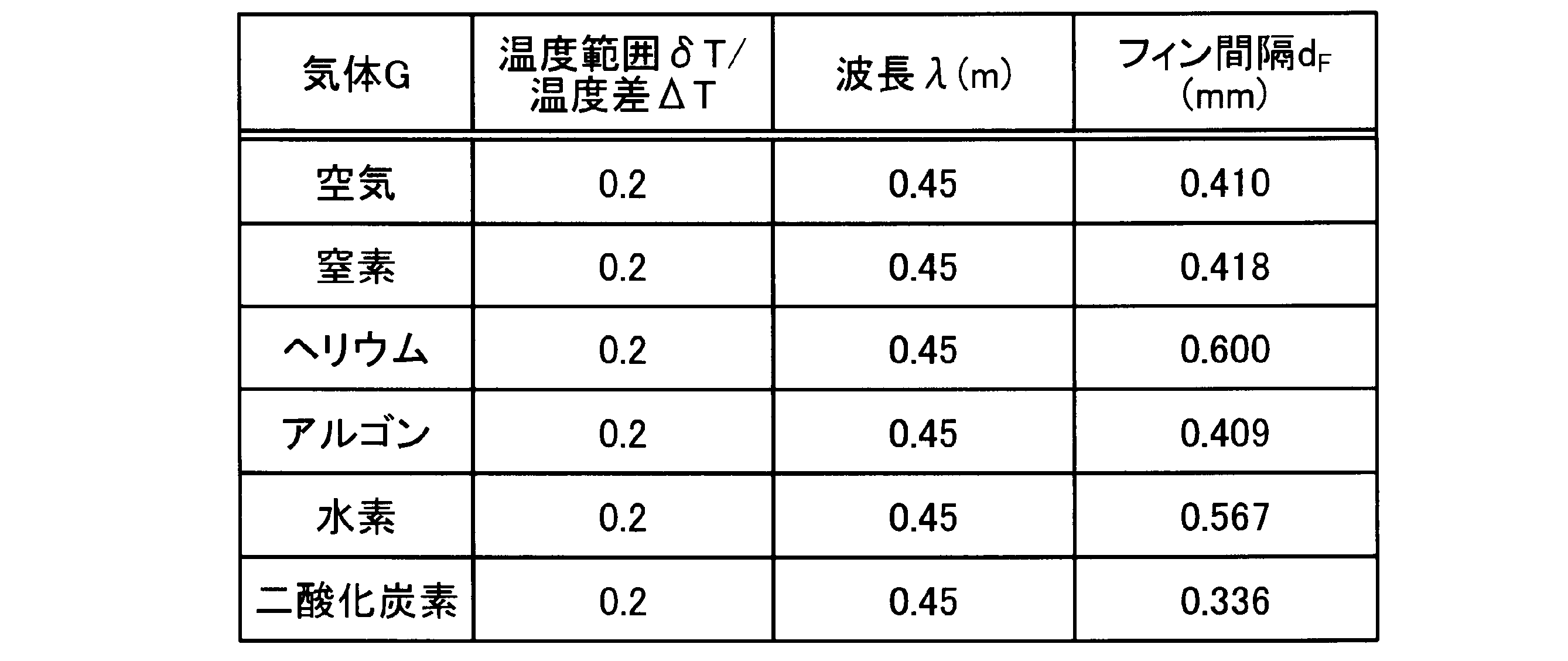
表1および表2は、気体Gの各々(空気、窒素、ヘリウム、アルゴン、水素、または二酸化炭素)について圧力PG、温度範囲δT/温度差ΔTの値、および音波の波長λが、それぞれ、1気圧、0.2、および45cmである場合における温度勾配保持部6の複数のフィン6aの間隔dFの設計例を示す。
図5は、実施形態に係る熱音響装置1における気体Gに伝わる熱量と複数のフィン6aに伝わる熱量との間の関係式に関する物理量を説明する図である。図5に示すように、熱交換器3の温度勾配保持部6は、温度差ΔTを保持する。熱交換器3の温度勾配保持部6の複数のフィン6aの間を移動する気体Gの熱伝導率および熱伝導有効長さをそれぞれκGおよびLGによって表す。ここで、気体Gの熱伝導有効長さLGは、熱交換器3の温度勾配保持部6の中心軸の方向(Z軸方向)における温度勾配保持部6の複数のフィン6aの一つにおける気体Gへの熱伝導の評価単位長さに対応する値である。
熱交換器3の温度勾配保持部6の中心軸の方向(Z軸方向)における複数のフィン6aの各々の長さをLFによって表す。温度勾配保持部6の複数のフィン6aの配列の方向(Y軸方向)における複数のフィン6aの各々の厚さをtFによって表す。複数のフィン6aの間の間隔をdFによって表す。複数のフィン6aの各々の熱伝導率をκFによって表す。
実施形態に係る熱音響装置1においては、温度差ΔTによって気体Gに伝わる熱量は、温度差ΔTによって複数のフィン6aの高温側の端から低温側の端に伝わる熱量より大きい。
温度差ΔTによって気体Gに伝わる熱量HGは、例えば、
HG=κG×ΔT×LG/(dF/2) ・・・・・(9)
の式によって表される。
HG=κG×ΔT×LG/(dF/2) ・・・・・(9)
の式によって表される。
温度差ΔTによって複数のフィン6aに伝わる熱量HFは、例えば、
HF=κF×ΔT×tF/LF ・・・・・(10)
の式によって表される。
HF=κF×ΔT×tF/LF ・・・・・(10)
の式によって表される。
式(9)および式(10)より、HG>HFが満たされる場合には、
κF<κG×(LG×LF)/{(dF/2)×tF} ・・・・・(11)
の式が満たされる。
κF<κG×(LG×LF)/{(dF/2)×tF} ・・・・・(11)
の式が満たされる。
すなわち、複数のフィン6aの熱伝導率κFが式(11)の関係を満たすように複数のフィン6aの材料を選択することによって、温度差ΔTによって気体Gに伝わる熱量HGは、温度差ΔTによって複数のフィン6aの高温側の端から低温側の端に伝わる熱量HFより大きいように熱音響装置1を設計することができる。
この場合には、複数のフィン6aの高温側の端から低温側の端への熱伝導と比べて複数のフィン6aと気体Gとの間の熱伝導の効率を高めることができる。それに応じて、実施形態に係る熱音響装置1は、熱エネルギーを音波の音響エネルギーに変換する効率を高めることができる。
例えば、気体Gの熱伝導有効長さLG、複数のフィン6aの各々の長さLF、複数のフィン6aの間の間隔dF、複数のフィン6aの各々の厚さtFが、それぞれ、1mm、10mm、2mm、および0.1mmであるとすれば、式(11)より、複数のフィン6aの熱伝導率κFおよび気体Gの熱伝導率κGは、κF<κG×100の関係を満たす。
例えば、気体Gが空気である場合には、気体Gの熱伝導率κGは、0.026W/(m・K)である。この場合には、複数のフィン6aの熱伝導率κFは、κF<2.6W/(m・K)の関係を満たす。κF<2.6W/(m・K)の関係を満たすような複数のフィン6aの材料は、例えば、ジルコニア、チタニア、またはステアタイトである。
実施形態に係る熱音響装置1においては、導波管2は気体Gが充填されるとしたが、導波管2は、気体G以外の媒体が充填されるとしてもよい。例えば、導波管2は、音波が有効に生成し、増幅される範囲において液体が充填されるとしてもよい。
実施形態に係る熱音響装置1においては、導波管2が単一のループの形状を有するとしたが、導波管2は、例えば、少なくとも一つの管で連結された複数のループの形状を有するとしてもよい。この場合には、熱音響装置1は、導波管2の同一のループまたは異なるループに複数の変換器8を有するものであってもよい。
実施形態に係る熱音響装置1においては、励振器7によって導波管2に充填された気体Gを振動または励振させるようにしたが、熱音響装置1は、励振器7を含まないものであってもよい。
この場合には、熱交換器3の低温部4と高温部5との間に温度差ΔTが生じる際に、導波管2に存在する1/fノイズを音源として気体Gに音波が生じる。気体Gに生じる音波は、熱交換器3の低温部4と高温部5との間に生じる温度差ΔTによって励振されると共に導波管2内において安定して共振する。
このように、熱音響装置1が励振器7を含まない場合であっても、熱音響装置1は、例えば、熱交換器3に供給される熱エネルギーを気体Gに生じる音波の音響エネルギーに変換することができる。
さらなる効果や変形例は、当業者によって容易に導き出すことができる。このため、本発明のより広範な態様は、以上のように表しかつ記述した特定の詳細および代表的な実施形態に限定されるものではない。したがって、添付の請求の範囲およびその均等物によって定義される総括的な発明の概念の精神または範囲から逸脱することなく、様々な変更が可能である。
1 熱音響装置
2 導波管
3 熱交換器
4 低温部
5 高温部
5a,5b フィン
6 温度勾配保持部
6a フィン
6b 仕切り
7 励振器
8 変換器
G 気体
2 導波管
3 熱交換器
4 低温部
5 高温部
5a,5b フィン
6 温度勾配保持部
6a フィン
6b 仕切り
7 励振器
8 変換器
G 気体
Claims (7)
- 媒体が充填されるループ状の導波管と、
前記導波管内に設けられ、低温部および高温部を有する熱交換器と、
を備え、
前記低温部と前記高温部との間に生じた温度勾配によって前記媒体に生じ、増幅される音波の位相速度が、前記温度勾配によって生じる前記媒体の昇温または降温速度に対応する、
熱音響装置。 - 前記熱交換器は、前記低温部と前記高温部との間に設けられ、前記温度勾配を保持する温度勾配保持部をさらに有する、請求項1に記載の熱音響装置。
- 前記温度勾配保持部は、複数のフィンを有し、
前記複数のフィンの間の間隔は、前記音波の位相速度が前記媒体の昇温または降温速度に対応するように設定される、
請求項2に記載の熱音響装置。 - 前記温度勾配によって前記媒体に伝わる熱量は、前記温度勾配によって前記複数のフィンの高温側の端から低温側の端に伝わる熱量より大きい、
請求項3に記載の熱音響装置。 - 前記導波管の長さは、前記音波の位相速度が前記媒体の昇温または降温速度に対応するように設定される、
請求項1から4のいずれか一項に記載の熱音響装置。 - 前記媒体は、前記音波の位相速度が前記媒体の昇温または降温速度に対応するように選択される、
請求項1から5のいずれか一項に記載の熱音響装置。 - 前記導波管に設けられ、前記音波を励振させる励振器
をさらに備える、請求項1から6のいずれか一項に記載の熱音響装置。
Applications Claiming Priority (2)
| Application Number | Priority Date | Filing Date | Title |
|---|---|---|---|
| JP2018-164017 | 2018-08-31 | ||
| JP2018164017 | 2018-08-31 |
Publications (1)
| Publication Number | Publication Date |
|---|---|
| WO2020045600A1 true WO2020045600A1 (ja) | 2020-03-05 |
Family
ID=69642815
Family Applications (1)
| Application Number | Title | Priority Date | Filing Date |
|---|---|---|---|
| PCT/JP2019/034025 Ceased WO2020045600A1 (ja) | 2018-08-31 | 2019-08-29 | 熱音響装置 |
Country Status (1)
| Country | Link |
|---|---|
| WO (1) | WO2020045600A1 (ja) |
Cited By (1)
| Publication number | Priority date | Publication date | Assignee | Title |
|---|---|---|---|---|
| WO2022024426A1 (ja) * | 2020-07-31 | 2022-02-03 | 京セラ株式会社 | 熱音響装置 |
Citations (2)
| Publication number | Priority date | Publication date | Assignee | Title |
|---|---|---|---|---|
| JP2005274101A (ja) * | 2004-03-26 | 2005-10-06 | Doshisha | 熱音響装置 |
| JP2008101910A (ja) * | 2008-01-16 | 2008-05-01 | Doshisha | 熱音響装置 |
-
2019
- 2019-08-29 WO PCT/JP2019/034025 patent/WO2020045600A1/ja not_active Ceased
Patent Citations (2)
| Publication number | Priority date | Publication date | Assignee | Title |
|---|---|---|---|---|
| JP2005274101A (ja) * | 2004-03-26 | 2005-10-06 | Doshisha | 熱音響装置 |
| JP2008101910A (ja) * | 2008-01-16 | 2008-05-01 | Doshisha | 熱音響装置 |
Cited By (1)
| Publication number | Priority date | Publication date | Assignee | Title |
|---|---|---|---|---|
| WO2022024426A1 (ja) * | 2020-07-31 | 2022-02-03 | 京セラ株式会社 | 熱音響装置 |
Similar Documents
| Publication | Publication Date | Title |
|---|---|---|
| Yazaki et al. | A pistonless Stirling cooler | |
| Poese et al. | Performance measurements on a thermoacoustic refrigerator driven at high amplitudes | |
| CN107449305B (zh) | 储热单元 | |
| US6910332B2 (en) | Thermoacoustic engine-generator | |
| CN110168291B (zh) | 热声装置 | |
| WO2006073007A1 (ja) | 熱音響装置 | |
| JPWO2004085934A1 (ja) | 冷却装置 | |
| Zolpakar et al. | Experimental investigations of the performance of a standing wave thermoacoustic refrigerator based on multi-objective genetic algorithm optimized parameters | |
| JP5570899B2 (ja) | 熱電気音響エンジン及びその使用方法 | |
| Zolpakar et al. | Performance of a 3D-printed stack in a standing wave thermoacoustic refrigerator | |
| US8371129B2 (en) | Standing wave thermoacoustic piezoelectric system and apparatus for generating electrical energy from heat energy | |
| Yao et al. | Study on heat pipe heat dissipation of high-power ultrasonic transducer | |
| Murti et al. | Analysis of multi-cylinder type liquid piston Stirling cooler | |
| JPWO2020045675A1 (ja) | 熱音響装置 | |
| WO2020045600A1 (ja) | 熱音響装置 | |
| Chen et al. | Experimental study on the cooling performances of thermoacoustic heat exchangers | |
| JPH0814679A (ja) | 熱音響冷凍サイクル及び冷却装置 | |
| JP6894050B1 (ja) | 熱音響装置 | |
| US10480832B2 (en) | Thermoacoustic energy converting element part and thermoacoustic energy converter | |
| WO2021152798A1 (ja) | 熱音響装置 | |
| Yoshida et al. | Forced synchronization of periodic oscillations in a gas column: Where is the power source? | |
| US8640467B2 (en) | Acoustic power transmitting unit for thermoacoustic systems | |
| JP2000337724A (ja) | 音響冷凍装置 | |
| JP7179170B2 (ja) | 自励振動ヒートパイプ冷却装置および当該冷却装置を搭載した鉄道車両 | |
| Piccolo et al. | Convective heat transport along a thermoacoustic couple in the transient regime |
Legal Events
| Date | Code | Title | Description |
|---|---|---|---|
| 121 | Ep: the epo has been informed by wipo that ep was designated in this application |
Ref document number: 19853672 Country of ref document: EP Kind code of ref document: A1 |
|
| NENP | Non-entry into the national phase |
Ref country code: DE |
|
| 122 | Ep: pct application non-entry in european phase |
Ref document number: 19853672 Country of ref document: EP Kind code of ref document: A1 |
|
| NENP | Non-entry into the national phase |
Ref country code: JP |