WO2020045385A1 - Blood purification device - Google Patents
Blood purification device Download PDFInfo
- Publication number
- WO2020045385A1 WO2020045385A1 PCT/JP2019/033425 JP2019033425W WO2020045385A1 WO 2020045385 A1 WO2020045385 A1 WO 2020045385A1 JP 2019033425 W JP2019033425 W JP 2019033425W WO 2020045385 A1 WO2020045385 A1 WO 2020045385A1
- Authority
- WO
- WIPO (PCT)
- Prior art keywords
- cassette
- blood purification
- main body
- water removal
- attached
- Prior art date
Links
Images


Classifications
-
- A—HUMAN NECESSITIES
- A61—MEDICAL OR VETERINARY SCIENCE; HYGIENE
- A61M—DEVICES FOR INTRODUCING MEDIA INTO, OR ONTO, THE BODY; DEVICES FOR TRANSDUCING BODY MEDIA OR FOR TAKING MEDIA FROM THE BODY; DEVICES FOR PRODUCING OR ENDING SLEEP OR STUPOR
- A61M1/00—Suction or pumping devices for medical purposes; Devices for carrying-off, for treatment of, or for carrying-over, body-liquids; Drainage systems
- A61M1/34—Filtering material out of the blood by passing it through a membrane, i.e. hemofiltration or diafiltration
- A61M1/3403—Regulation parameters
- A61M1/341—Regulation parameters by measuring the filtrate rate or volume
-
- A—HUMAN NECESSITIES
- A61—MEDICAL OR VETERINARY SCIENCE; HYGIENE
- A61M—DEVICES FOR INTRODUCING MEDIA INTO, OR ONTO, THE BODY; DEVICES FOR TRANSDUCING BODY MEDIA OR FOR TAKING MEDIA FROM THE BODY; DEVICES FOR PRODUCING OR ENDING SLEEP OR STUPOR
- A61M1/00—Suction or pumping devices for medical purposes; Devices for carrying-off, for treatment of, or for carrying-over, body-liquids; Drainage systems
- A61M1/14—Dialysis systems; Artificial kidneys; Blood oxygenators ; Reciprocating systems for treatment of body fluids, e.g. single needle systems for hemofiltration or pheresis
- A61M1/16—Dialysis systems; Artificial kidneys; Blood oxygenators ; Reciprocating systems for treatment of body fluids, e.g. single needle systems for hemofiltration or pheresis with membranes
- A61M1/1621—Constructional aspects thereof
- A61M1/1629—Constructional aspects thereof with integral heat exchanger
-
- A—HUMAN NECESSITIES
- A61—MEDICAL OR VETERINARY SCIENCE; HYGIENE
- A61M—DEVICES FOR INTRODUCING MEDIA INTO, OR ONTO, THE BODY; DEVICES FOR TRANSDUCING BODY MEDIA OR FOR TAKING MEDIA FROM THE BODY; DEVICES FOR PRODUCING OR ENDING SLEEP OR STUPOR
- A61M1/00—Suction or pumping devices for medical purposes; Devices for carrying-off, for treatment of, or for carrying-over, body-liquids; Drainage systems
- A61M1/14—Dialysis systems; Artificial kidneys; Blood oxygenators ; Reciprocating systems for treatment of body fluids, e.g. single needle systems for hemofiltration or pheresis
- A61M1/15—Dialysis systems; Artificial kidneys; Blood oxygenators ; Reciprocating systems for treatment of body fluids, e.g. single needle systems for hemofiltration or pheresis with a cassette forming partially or totally the flow circuit for the treating fluid, e.g. the dialysate fluid circuit or the treating gas circuit
- A61M1/152—Details related to the interface between cassette and machine
-
- A—HUMAN NECESSITIES
- A61—MEDICAL OR VETERINARY SCIENCE; HYGIENE
- A61M—DEVICES FOR INTRODUCING MEDIA INTO, OR ONTO, THE BODY; DEVICES FOR TRANSDUCING BODY MEDIA OR FOR TAKING MEDIA FROM THE BODY; DEVICES FOR PRODUCING OR ENDING SLEEP OR STUPOR
- A61M1/00—Suction or pumping devices for medical purposes; Devices for carrying-off, for treatment of, or for carrying-over, body-liquids; Drainage systems
- A61M1/14—Dialysis systems; Artificial kidneys; Blood oxygenators ; Reciprocating systems for treatment of body fluids, e.g. single needle systems for hemofiltration or pheresis
- A61M1/15—Dialysis systems; Artificial kidneys; Blood oxygenators ; Reciprocating systems for treatment of body fluids, e.g. single needle systems for hemofiltration or pheresis with a cassette forming partially or totally the flow circuit for the treating fluid, e.g. the dialysate fluid circuit or the treating gas circuit
- A61M1/153—Dialysis systems; Artificial kidneys; Blood oxygenators ; Reciprocating systems for treatment of body fluids, e.g. single needle systems for hemofiltration or pheresis with a cassette forming partially or totally the flow circuit for the treating fluid, e.g. the dialysate fluid circuit or the treating gas circuit the cassette being adapted for heating or cooling the treating fluid, e.g. the dialysate or the treating gas
-
- A—HUMAN NECESSITIES
- A61—MEDICAL OR VETERINARY SCIENCE; HYGIENE
- A61M—DEVICES FOR INTRODUCING MEDIA INTO, OR ONTO, THE BODY; DEVICES FOR TRANSDUCING BODY MEDIA OR FOR TAKING MEDIA FROM THE BODY; DEVICES FOR PRODUCING OR ENDING SLEEP OR STUPOR
- A61M1/00—Suction or pumping devices for medical purposes; Devices for carrying-off, for treatment of, or for carrying-over, body-liquids; Drainage systems
- A61M1/14—Dialysis systems; Artificial kidneys; Blood oxygenators ; Reciprocating systems for treatment of body fluids, e.g. single needle systems for hemofiltration or pheresis
- A61M1/15—Dialysis systems; Artificial kidneys; Blood oxygenators ; Reciprocating systems for treatment of body fluids, e.g. single needle systems for hemofiltration or pheresis with a cassette forming partially or totally the flow circuit for the treating fluid, e.g. the dialysate fluid circuit or the treating gas circuit
- A61M1/155—Dialysis systems; Artificial kidneys; Blood oxygenators ; Reciprocating systems for treatment of body fluids, e.g. single needle systems for hemofiltration or pheresis with a cassette forming partially or totally the flow circuit for the treating fluid, e.g. the dialysate fluid circuit or the treating gas circuit with treatment-fluid pumping means or components thereof
-
- A—HUMAN NECESSITIES
- A61—MEDICAL OR VETERINARY SCIENCE; HYGIENE
- A61M—DEVICES FOR INTRODUCING MEDIA INTO, OR ONTO, THE BODY; DEVICES FOR TRANSDUCING BODY MEDIA OR FOR TAKING MEDIA FROM THE BODY; DEVICES FOR PRODUCING OR ENDING SLEEP OR STUPOR
- A61M1/00—Suction or pumping devices for medical purposes; Devices for carrying-off, for treatment of, or for carrying-over, body-liquids; Drainage systems
- A61M1/14—Dialysis systems; Artificial kidneys; Blood oxygenators ; Reciprocating systems for treatment of body fluids, e.g. single needle systems for hemofiltration or pheresis
- A61M1/15—Dialysis systems; Artificial kidneys; Blood oxygenators ; Reciprocating systems for treatment of body fluids, e.g. single needle systems for hemofiltration or pheresis with a cassette forming partially or totally the flow circuit for the treating fluid, e.g. the dialysate fluid circuit or the treating gas circuit
- A61M1/156—Constructional details of the cassette, e.g. specific details on material or shape
- A61M1/1562—Details of incorporated reservoirs
-
- A—HUMAN NECESSITIES
- A61—MEDICAL OR VETERINARY SCIENCE; HYGIENE
- A61M—DEVICES FOR INTRODUCING MEDIA INTO, OR ONTO, THE BODY; DEVICES FOR TRANSDUCING BODY MEDIA OR FOR TAKING MEDIA FROM THE BODY; DEVICES FOR PRODUCING OR ENDING SLEEP OR STUPOR
- A61M1/00—Suction or pumping devices for medical purposes; Devices for carrying-off, for treatment of, or for carrying-over, body-liquids; Drainage systems
- A61M1/14—Dialysis systems; Artificial kidneys; Blood oxygenators ; Reciprocating systems for treatment of body fluids, e.g. single needle systems for hemofiltration or pheresis
- A61M1/15—Dialysis systems; Artificial kidneys; Blood oxygenators ; Reciprocating systems for treatment of body fluids, e.g. single needle systems for hemofiltration or pheresis with a cassette forming partially or totally the flow circuit for the treating fluid, e.g. the dialysate fluid circuit or the treating gas circuit
- A61M1/156—Constructional details of the cassette, e.g. specific details on material or shape
- A61M1/1563—Details of incorporated filters
- A61M1/15632—Details of incorporated filters the filter being a dialyser
-
- A—HUMAN NECESSITIES
- A61—MEDICAL OR VETERINARY SCIENCE; HYGIENE
- A61M—DEVICES FOR INTRODUCING MEDIA INTO, OR ONTO, THE BODY; DEVICES FOR TRANSDUCING BODY MEDIA OR FOR TAKING MEDIA FROM THE BODY; DEVICES FOR PRODUCING OR ENDING SLEEP OR STUPOR
- A61M1/00—Suction or pumping devices for medical purposes; Devices for carrying-off, for treatment of, or for carrying-over, body-liquids; Drainage systems
- A61M1/14—Dialysis systems; Artificial kidneys; Blood oxygenators ; Reciprocating systems for treatment of body fluids, e.g. single needle systems for hemofiltration or pheresis
- A61M1/16—Dialysis systems; Artificial kidneys; Blood oxygenators ; Reciprocating systems for treatment of body fluids, e.g. single needle systems for hemofiltration or pheresis with membranes
-
- A—HUMAN NECESSITIES
- A61—MEDICAL OR VETERINARY SCIENCE; HYGIENE
- A61M—DEVICES FOR INTRODUCING MEDIA INTO, OR ONTO, THE BODY; DEVICES FOR TRANSDUCING BODY MEDIA OR FOR TAKING MEDIA FROM THE BODY; DEVICES FOR PRODUCING OR ENDING SLEEP OR STUPOR
- A61M1/00—Suction or pumping devices for medical purposes; Devices for carrying-off, for treatment of, or for carrying-over, body-liquids; Drainage systems
- A61M1/36—Other treatment of blood in a by-pass of the natural circulatory system, e.g. temperature adaptation, irradiation ; Extra-corporeal blood circuits
- A61M1/3621—Extra-corporeal blood circuits
- A61M1/3622—Extra-corporeal blood circuits with a cassette forming partially or totally the blood circuit
- A61M1/36222—Details related to the interface between cassette and machine
-
- A—HUMAN NECESSITIES
- A61—MEDICAL OR VETERINARY SCIENCE; HYGIENE
- A61M—DEVICES FOR INTRODUCING MEDIA INTO, OR ONTO, THE BODY; DEVICES FOR TRANSDUCING BODY MEDIA OR FOR TAKING MEDIA FROM THE BODY; DEVICES FOR PRODUCING OR ENDING SLEEP OR STUPOR
- A61M1/00—Suction or pumping devices for medical purposes; Devices for carrying-off, for treatment of, or for carrying-over, body-liquids; Drainage systems
- A61M1/36—Other treatment of blood in a by-pass of the natural circulatory system, e.g. temperature adaptation, irradiation ; Extra-corporeal blood circuits
- A61M1/3621—Extra-corporeal blood circuits
- A61M1/3622—Extra-corporeal blood circuits with a cassette forming partially or totally the blood circuit
- A61M1/36223—Extra-corporeal blood circuits with a cassette forming partially or totally the blood circuit the cassette being adapted for heating or cooling the blood
-
- A—HUMAN NECESSITIES
- A61—MEDICAL OR VETERINARY SCIENCE; HYGIENE
- A61M—DEVICES FOR INTRODUCING MEDIA INTO, OR ONTO, THE BODY; DEVICES FOR TRANSDUCING BODY MEDIA OR FOR TAKING MEDIA FROM THE BODY; DEVICES FOR PRODUCING OR ENDING SLEEP OR STUPOR
- A61M1/00—Suction or pumping devices for medical purposes; Devices for carrying-off, for treatment of, or for carrying-over, body-liquids; Drainage systems
- A61M1/36—Other treatment of blood in a by-pass of the natural circulatory system, e.g. temperature adaptation, irradiation ; Extra-corporeal blood circuits
- A61M1/3621—Extra-corporeal blood circuits
- A61M1/3622—Extra-corporeal blood circuits with a cassette forming partially or totally the blood circuit
- A61M1/36225—Extra-corporeal blood circuits with a cassette forming partially or totally the blood circuit with blood pumping means or components thereof
-
- A—HUMAN NECESSITIES
- A61—MEDICAL OR VETERINARY SCIENCE; HYGIENE
- A61M—DEVICES FOR INTRODUCING MEDIA INTO, OR ONTO, THE BODY; DEVICES FOR TRANSDUCING BODY MEDIA OR FOR TAKING MEDIA FROM THE BODY; DEVICES FOR PRODUCING OR ENDING SLEEP OR STUPOR
- A61M1/00—Suction or pumping devices for medical purposes; Devices for carrying-off, for treatment of, or for carrying-over, body-liquids; Drainage systems
- A61M1/36—Other treatment of blood in a by-pass of the natural circulatory system, e.g. temperature adaptation, irradiation ; Extra-corporeal blood circuits
- A61M1/3621—Extra-corporeal blood circuits
- A61M1/3622—Extra-corporeal blood circuits with a cassette forming partially or totally the blood circuit
- A61M1/36226—Constructional details of cassettes, e.g. specific details on material or shape
- A61M1/362262—Details of incorporated reservoirs
-
- A—HUMAN NECESSITIES
- A61—MEDICAL OR VETERINARY SCIENCE; HYGIENE
- A61M—DEVICES FOR INTRODUCING MEDIA INTO, OR ONTO, THE BODY; DEVICES FOR TRANSDUCING BODY MEDIA OR FOR TAKING MEDIA FROM THE BODY; DEVICES FOR PRODUCING OR ENDING SLEEP OR STUPOR
- A61M1/00—Suction or pumping devices for medical purposes; Devices for carrying-off, for treatment of, or for carrying-over, body-liquids; Drainage systems
- A61M1/14—Dialysis systems; Artificial kidneys; Blood oxygenators ; Reciprocating systems for treatment of body fluids, e.g. single needle systems for hemofiltration or pheresis
- A61M1/16—Dialysis systems; Artificial kidneys; Blood oxygenators ; Reciprocating systems for treatment of body fluids, e.g. single needle systems for hemofiltration or pheresis with membranes
- A61M1/1694—Dialysis systems; Artificial kidneys; Blood oxygenators ; Reciprocating systems for treatment of body fluids, e.g. single needle systems for hemofiltration or pheresis with membranes with recirculating dialysing liquid
- A61M1/1696—Dialysis systems; Artificial kidneys; Blood oxygenators ; Reciprocating systems for treatment of body fluids, e.g. single needle systems for hemofiltration or pheresis with membranes with recirculating dialysing liquid with dialysate regeneration
-
- A—HUMAN NECESSITIES
- A61—MEDICAL OR VETERINARY SCIENCE; HYGIENE
- A61M—DEVICES FOR INTRODUCING MEDIA INTO, OR ONTO, THE BODY; DEVICES FOR TRANSDUCING BODY MEDIA OR FOR TAKING MEDIA FROM THE BODY; DEVICES FOR PRODUCING OR ENDING SLEEP OR STUPOR
- A61M2205/00—General characteristics of the apparatus
- A61M2205/12—General characteristics of the apparatus with interchangeable cassettes forming partially or totally the fluid circuit
- A61M2205/123—General characteristics of the apparatus with interchangeable cassettes forming partially or totally the fluid circuit with incorporated reservoirs
-
- A—HUMAN NECESSITIES
- A61—MEDICAL OR VETERINARY SCIENCE; HYGIENE
- A61M—DEVICES FOR INTRODUCING MEDIA INTO, OR ONTO, THE BODY; DEVICES FOR TRANSDUCING BODY MEDIA OR FOR TAKING MEDIA FROM THE BODY; DEVICES FOR PRODUCING OR ENDING SLEEP OR STUPOR
- A61M2205/00—General characteristics of the apparatus
- A61M2205/12—General characteristics of the apparatus with interchangeable cassettes forming partially or totally the fluid circuit
- A61M2205/125—General characteristics of the apparatus with interchangeable cassettes forming partially or totally the fluid circuit with incorporated filters
-
- A—HUMAN NECESSITIES
- A61—MEDICAL OR VETERINARY SCIENCE; HYGIENE
- A61M—DEVICES FOR INTRODUCING MEDIA INTO, OR ONTO, THE BODY; DEVICES FOR TRANSDUCING BODY MEDIA OR FOR TAKING MEDIA FROM THE BODY; DEVICES FOR PRODUCING OR ENDING SLEEP OR STUPOR
- A61M2205/00—General characteristics of the apparatus
- A61M2205/33—Controlling, regulating or measuring
- A61M2205/332—Force measuring means
-
- A—HUMAN NECESSITIES
- A61—MEDICAL OR VETERINARY SCIENCE; HYGIENE
- A61M—DEVICES FOR INTRODUCING MEDIA INTO, OR ONTO, THE BODY; DEVICES FOR TRANSDUCING BODY MEDIA OR FOR TAKING MEDIA FROM THE BODY; DEVICES FOR PRODUCING OR ENDING SLEEP OR STUPOR
- A61M2205/00—General characteristics of the apparatus
- A61M2205/33—Controlling, regulating or measuring
- A61M2205/3379—Masses, volumes, levels of fluids in reservoirs, flow rates
- A61M2205/3393—Masses, volumes, levels of fluids in reservoirs, flow rates by weighing the reservoir
Definitions
- the present invention relates to the structure of a blood purification device.
- a blood purification device in which a cassette containing a dialyzer, a pump tube, a blood circuit and the like is detachably attached to a main body on which a pump rotor and a control device are mounted.
- the pump tube of the cassette is sequentially crushed by the pump rotor of the main body, and blood and dialysate are pumped to a dialyzer or the like (for example, Patent Document 1). reference).
- JP 2007-97746 A Japanese Patent No. 5657726
- an object of the present invention is to simplify the handling of the blood purification device.
- the blood purification device of the present invention is a blood purification device having a device main body and a cassette detachably attached to the device main body, wherein the cassette has a casing for housing a water removal container, It is detachable from the main body.
- the water removal container is attached to the cassette and can be integrally attached to and detached from the apparatus main body, the handling of the blood purification apparatus can be simplified.
- a load detection unit that measures a load of the water removal container is attached to the device main body, and transmits a load of the water removal container stored in the cassette to the load detection unit. It may have a load transmitting mechanism.
- the load transmission mechanism includes a hole provided in a bottom plate of a portion of the cassette that houses the water removal container, and the water removal container is placed on the load detection unit. Things.
- the apparatus main body may include a base to which the load detection unit is attached, and the load detection unit may be inserted through the hole.
- the apparatus main body has a cassette receiver for receiving the cassette, and the load transmitting mechanism includes the hole and an opening provided in the cassette receiver at a position corresponding to the hole of the cassette. And the load detector may be inserted through the hole and the opening.
- the device main body includes a base to which the load detection unit is attached, and the load transmission mechanism is configured to insert the hole and the load detection unit through the hole and attached to the base.
- a spacer that is sandwiched between the unit and the bottom surface of the water removal container to float the water removal container from the bottom plate of the cassette, wherein the water removal container is placed on the load detection unit via the spacer.
- the apparatus main body has a cassette receiver for receiving the cassette, the cassette receiver is attached with a gap between the cassette receiver and the base, and the load transmission mechanism is provided with the hole of the cassette.
- the cassette receiving seat Further comprising an opening provided in the cassette receiving seat at a position corresponding to the above, wherein the spacer is inserted through the hole and the opening, the cassette is attached to the apparatus main body, and the bottom surface of the cassette is the apparatus main body.
- the water detection container When in contact with the cassette receiver, the water detection container is sandwiched between the load detection unit attached to the base and the bottom surface of the water removal container, and the water removal container is lifted from the bottom plate of the cassette. Is also good.
- the load transmitting mechanism includes an opening provided on a ceiling plate of a portion of the cassette that accommodates the water removal container, and an engaged portion protruding above the water removal container, And the water removal container may be suspended from the load detection unit.
- the load transmitting mechanism is connected to the load detection unit attached to the housing, and the water removal container is inserted through the opening when the cassette is attached to the housing. Including an engaging portion that engages with the engaged portion to float the water removal container from the bottom plate of the cassette, wherein the water removal container is suspended from the load detection unit via the engagement portion, Is also good.
- the device body may be provided with a heating element such that a part or all of the device enters the cassette when the cassette is attached to the device body.
- a heating element such that a part or all of the device enters the cassette when the cassette is attached to the device body.
- the heating element when the cassette is attached to the apparatus main body, the heating element is disposed in an area below the water removal container accommodated in the cassette, and a part or all of the heating element is disposed from below. You may make it enter inside the said cassette.
- a concave portion may be provided at the bottom of the water removing container, and the heating element may enter the concave portion from below when the cassette is attached to the apparatus main body. Further, the heating element may enter the inside of the cassette from a side surface or an upper side of the cassette.
- a heating element may be arranged in the apparatus main body such that the heating element is located near the cassette when the cassette is attached to the apparatus main body.
- the heating body may be located near the lower side of the cassette when the cassette is attached to the apparatus main body.
- the heating body when the cassette is attached, the heating body may be located near a side surface of the cassette.
- the heating element when the cassette is mounted, the heating element may be located near the upper side of the cassette.
- the weight of the water removal container housed in the cassette can be measured by the device body housing the load detection unit with a simple structure, and the dialysate is heated and returned to the patient. Blood temperature can be maintained.
- the cassette may further contain a dialyzer and a dialysate regeneration column.
- a pump tube having elasticity, a tube receiving member for receiving the pump tube, a tube pressing member for pressing a part of the pump tube against the tube receiving member, and the tube pressing member
- a drive unit for moving the pump tube in the longitudinal direction, a pump unit for extruding a liquid inside the pump tube, the cassette includes at least a part of the pump unit, and the device body includes And another part of the pump unit.
- the cassette includes the tube receiving member and the pump tube of the pump unit
- the apparatus main body includes the tube pressing body and the driving unit
- the tube receiving member includes the tube receiving member of the cassette.
- a casing wherein the pump tube is attached to an outer surface of the casing, the tube pressing body is a plurality of fingers, and the cassette is such that the pump tube is located between the fingers and the outer surface of the casing. It may be detachable from the apparatus main body.
- the cassette includes the tube receiving member of the pump section, the pump tube, and the tube pressing body, the apparatus main body includes the driving section, and the tube pressing body is a rotor.
- the pump tube includes an arc portion along the outer periphery of the rotor, the tube receiving member is a stator including an arc portion along the outer periphery of the pump tube, and the cassette is attached to the apparatus main body.
- the rotor may be detachably attached to the device main body such that the rotor is engaged with the drive unit when the drive unit is removed, and the rotor is separated from the drive unit when the rotor is detached from the device main unit.
- the handling of the blood purification device can be simplified.
- FIG. 5 is a sectional view taken along the line AA shown in FIG. 4. It is an explanatory view showing a load transmission mechanism of a blood purification device of another embodiment. It is an explanatory view showing a load transmission mechanism of a blood purification device of another embodiment. It is sectional drawing which shows the load transmission mechanism in the modification of the blood purification apparatus shown in FIG. It is sectional drawing which shows the other modification of the blood purification measure shown in FIG.
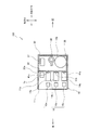
- FIG. 11 is a plan sectional view showing another modified example of the blood purification device shown in FIG. 1.
- FIG. 11 is a plan sectional view showing another modified example of the blood purification device shown in FIG. 1.
- FIG. 11 is a plan sectional view showing another modified example of the blood purification device shown in FIG. 1.
- FIG. 11 is a plan sectional view showing another modified example of the blood purification device shown in FIG. 1.
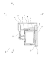
- FIG. 9 is an exploded perspective view showing another modified example of the blood purification device shown in FIG. 1.
- It is sectional drawing of the blood purification apparatus shown in FIG. It is sectional drawing which shows the modification of the blood purification apparatus shown in FIG. It is sectional drawing which shows the other modification of the blood purification apparatus shown in FIG.
- It is sectional drawing which shows the other modification of the blood purification apparatus shown in FIG.
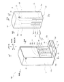
- the blood purification device 100 includes a device main body 10 and a cassette 30 that is detachably attached to the device main body 10.
- the cassette 30 is attached to the apparatus main body 10 by fitting the lower part into the cassette seat 13 of the apparatus main body 10 and fastening the upper claw 35 with the metal fitting 18 of the apparatus main body 10.
- the blood inlet nozzle 51a and the blood outlet nozzle 51b of the cassette 30 are respectively connected to blood vessels of a human body.
- the arrangement direction of the apparatus main body 10 and the cassette 30 will be described as the front-rear direction, the direction perpendicular to the front-rear direction on the horizontal plane as the width direction, and the vertical direction as the up-down direction.
- the casing 31 of the cassette 30 contains a dialyzer 36, a dialysate regeneration column 38, and a water removal container 37, and an outer surface 32 a of a rear plate 32 of the casing 31 has a plurality of elastic members.
- Pump tubes 41 (41a to 41c) are attached.
- the casing 31 forms a tube receiving member that receives the pump tube 41.
- the apparatus main body 10 includes a finger casing 14 for accommodating a plurality of fingers 15, a driving unit 16 for the fingers 15, a control unit 20 for controlling the driving of the driving unit 16, and a housing for accommodating these. And a body 11.
- the finger 15 is a tube pressing body that allows the liquid inside to flow by moving the compression position in the longitudinal direction of the pump tube 41 while compressing the pump tube 41 in the radial direction.
- the finger 15 and the finger casing 14 constitute a peristaltic pump which is a pump unit.
- the blood purification apparatus 100 includes a blood circuit and a dialysate circuit.
- the blood circuit is a liquid circuit that returns blood from the human body flowing from the blood inlet nozzle 51a to the human body from the blood outlet nozzle 51b, and includes a pump tube 41a of the blood pump, a blood-side flow path of the dialyzer 36, a drip chamber, and the like. It consists of connecting pipes to connect.
- the dialysate circuit is a liquid circuit that circulates the dialysate through the dialyzer 36, and includes a dialysate-side flow path of the dialyzer 36, a dialysate regeneration column 38, a dewatering container 37, a pump tube 41b of a dialysate outlet pump, and a dialysate. It is composed of a pump tube 41c of the liquid inlet pump and a connecting pipe connecting these.
- the dialysate regeneration column 38 may be installed at any place in the dialysate circuit.
- the blood purification apparatus 100 is for flowing blood to a blood circuit, flowing dialysate to a dialysate circuit, and removing unnecessary waste and excess water in blood by a dialyzer 36.
- the blood circuit and the dialysate circuit constitute a liquid contact part.
- the cassette 30 includes a dialyzer 36, a dialysate regeneration column 38, a dewatering container 37, a drip chamber, pump tubes 41a to 41c, a blood inlet nozzle 51a, and a blood outlet which constitute a liquid contact part.
- a nozzle 51b and a connection pipe for connecting these nozzles are attached.
- the pump tubes 41a to 41c correspond to a blood pump, a dialysate outlet pump, and a dialysate inlet pump, respectively.
- the present invention is not limited thereto, and the pump tubes 41a to 41c may be blood pumps, dialysate outlet pumps, respectively. And a dialysate inlet pump.
- the housing 11 of the apparatus main body 10 includes a square base 12, L-shaped left and right side plates 11 a, a front plate 11 b attached to the front side of the base 12, and a cassette seat 13. It has. As shown in FIG. 3A, a rib 12a is attached to the center of the base 12, and the cassette seat 13 is mounted on the front portions of the left and right side plates 11a, the front plate 11b, and the ribs 12a. I have. As described above, the cassette receiving seat 13 is attached with a gap between the cassette receiving seat 13 and the base 12.
- the cassette receiving seat 13 has a flat receiving plate 13a mounted on the front portions of the left and right side plates 11a, the front plate 11b and the ribs 12a, and on which the bottom plate 34 of the cassette 30 is placed. And a longitudinal flange 13b erected at the both ends in the width direction of the receiving plate 13a and the front end. The inner surface of the vertical flange 13b is inclined outward so as to easily receive the cassette 30, as shown in FIG.
- Finger casings 14a to 14c constituting a blood pump, a dialysate outlet pump, and a dialysate inlet pump are attached to the upper surface of the base 12.
- the drive units 16a to 16c are attached to the finger casings 14a to 14c.
- the casing 31 of the cassette 30 includes a bottom plate 34, a rear plate 32 erected vertically from the rear edge of the bottom plate 34, and both end edges in the width direction of the bottom plate 34. It includes a side plate 31a standing upright and a front plate 31b standing upright from the front edge of the bottom plate.
- a dialyzer 36, a dialysate regeneration column 38, and a water removal container 37 are accommodated in a space surrounded by the bottom plate 34.
- a dialyzer 36, a dialysate regeneration column 38, and a water removal container 37 are accommodated in a space surrounded by the bottom plate 34, the side plate 31a, the front plate 31b, and the rear plate 32.
- a connection pipe for connecting the dialyzer 36, the dialysate regeneration column 38, and the water removal container 37 is also accommodated in the cassette 30.
- Pump tubes 41a to 41c are attached to the flat outer surface 32a of the rear plate 32 on the device body side. Both ends of the pump tubes 41a to 41c are connected to a blood circuit and a dialysate circuit. The surface on the rear plate 32 side of the pump tubes 41a to 41c is arranged along the flat outer surface 32a of the rear plate 32.
- each of the finger casings 14a to 14c is provided with a vertically extending groove into which each of the pump tubes 41a to 41c is fitted.
- the pump tubes 41 a to 41 c are connected to the grooves of the finger casings 14 a to 14 c and the rear plate. 32 between the flat outer surface 32a.
- the elastic pump tubes 41a to 41c are pressed by the fingers 15a to 15c, respectively, as shown in FIG.
- FIG. 5 is a sectional view taken along the line AA shown in FIG. 4, and is a sectional view of a portion of the cassette 30 that accommodates the water removal container 37.
- a hole 34c is provided in the bottom plate 34 of the cassette 30 in which the water removal container 37 is stored.
- An opening 13c is provided in the cassette seat 13 at a position corresponding to the hole 34c of the bottom plate 34 of the cassette 30.
- the hole 34c and the opening 13c constitute one through hole.
- the spacer 22 is inserted into the through hole formed by the hole 34c and the opening 13c, and the load detecting unit 21 for measuring the load of the water removal container 37 is attached to the upper surface of the base 12 below the spacer 22. I have.
- the spacer 22 projects from the upper surface 34b of the bottom plate 34 when the cassette 30 is attached to the apparatus main body 10 and the lower surface 34a of the bottom plate 34 contacts the upper surface 13d of the cassette seat 13.
- the thickness is such that it can be lifted from the upper surface 34b.
- the load of the water removing container 37 is supported by the upper surface 34 b of the bottom plate 34 of the casing 31.
- the cassette 30 is attached to the housing 11 of the apparatus main body 10, and when the lower surface 34 a of the bottom plate 34 approaches the upper surface 13 d of the cassette seat 13, the upper surface of the spacer 22 projects from the upper surface 34 b of the bottom plate 34.
- the cassette 30 is attached to the housing 11 of the apparatus main body 10 and the lower surface 34a of the bottom plate 34 is in contact with the upper surface 13d of the cassette seat 13, as shown by a solid line in FIG.
- the bottom surface 37a of the water removal container 37 protruding from the upper surface 34b of the bottom plate 34 is floated from the upper surface 34b of the bottom plate 34.
- the spacer 22 is sandwiched between the load detection unit 21 and the bottom surface 37a of the water removal container 37, and transmits the load of the water removal container 37 to the load detection unit 21.
- the water removal container 37 is placed on the load detection unit 21, and the load of the water removal container 37 stored in the cassette 30 can be measured by the load detection unit 21 attached to the apparatus main body 10. it can.
- the load detection unit 21 measures the load of the water removing container 37 that stores the liquid, not the weight of the entire cassette 30, the load of the water removing container 37 can be accurately measured.
- the hole 34 c provided in the bottom plate 34 of the cassette 30, the opening 13 c provided in the cassette receiving seat 13, and the spacer 22 inserted into the hole 34 c and the opening 13 c apply the load of the water removal container 37 to the load.
- the load transmission mechanism that transmits the load to the detection unit 21 is configured.
- the load detecting section 21 and the spacer 22 are described as separate bodies.
- the present invention is not limited to this, and the load detecting section 21 may be provided with a hole 34 c provided in the bottom plate 34 of the cassette 30 and a cassette receiving seat. 13
- the cassette 30 is attached to the housing 11 of the apparatus main body 10, the upper surface of the load detector 21 projects from the upper surface 34 b of the bottom plate 34, and the water removal container 37 detects the load. You may comprise so that it may be directly mounted on the part 21.
- the cassette receiving seat 13 is not provided, and a concave portion is provided in a region corresponding to the hole 34c provided in the bottom plate 34 of the cassette 30 of the base 12, and the load detecting portion 21 is mounted in the concave portion.
- the upper surface of the load detector 21 projects from the upper surface 34b of the bottom plate 34 in a state where the cassette 30 is inserted into the hole 34c and the cassette 30 is attached to the housing 11 of the apparatus main body 10, and the water removal container 37 is placed on the load detector 21. May be configured.
- the upper surface of the spacer 22 protrudes from the upper surface 34b of the bottom plate 34 in a state where the spacer 22 is superimposed on the load detection unit 21 and the cassette 30 is attached to the housing 11 of the apparatus main body 10, and 37 may be configured to be placed on the spacer 22.
- the blood purification apparatus 100 of the present embodiment connects the blood circuit, the dialyzer 36 constituting the dialysate circuit, the water removal container 37, the dialysate regeneration column 38, the pump tubes 41a to 41c, and the devices.
- the connection pipe to be connected is integrally accommodated in the cassette 30 so as to be detachable from the apparatus main body 10. Therefore, dialysis can be performed only by attaching the cassette 30 to the apparatus main body 10 and connecting the blood inlet nozzle 51a and the blood outlet nozzle 51b to a puncture needle inserted into a blood vessel of a human body. Can be simplified.
- the cassette 30 stores all the disposables in the liquid contact portion of the blood circuit and the dialysate circuit, the disposables can be collectively disposed of by disposing the cassette 30 in a disposable manner. Thereby, handling of blood purification apparatus 100 can be simplified.
- the tube pressing body of the pump unit is described as the finger 15, and the tube receiving member is described as the casing 31, and the pressing position is set while the pump tube 41 is pressed in the radial direction.
- a peristaltic pump that pushes the liquid inside by moving it in the longitudinal direction of the tube 41
- the invention is not limited thereto, and an ironing type roller pump may be used.
- the tube pressing body of the pump portion is a rotor
- the pump tube 41 includes an arc portion along the outer periphery of the rotor
- the pump tube 41 includes a circular arc portion along the outer periphery of the pump tube 41. Is pressed by the stator.
- a stator, a rotor, and a pump tube are attached to the cassette 30, a drive unit is attached to the apparatus main body 10, and when the cassette 30 is attached to the apparatus main body 10, the rotor engages with the drive unit.
- the rotor may be detachable from the device main body 10 so that the rotor is separated from the drive unit when the rotor is detached from the device main body 10.
- a pump tube 41 including an arc portion along the outer periphery of the rotor and a stator including an arc portion along the outer periphery of the pump tube 41 are attached to the casing 31 of the cassette 30, and the apparatus is mounted.
- the rotor and the drive unit may be attached to the main body 10, and the cassette 30 may be detachable from the main body 10 so that the pump tube 41 is located between the rotor and the stator.
- the cassette 30 when the cassette 30 is attached to the housing 11 of the apparatus main body 10, the cassette 30 Since the load of only the water removal container 37 accommodated in the blood purification device 100 can be measured, the handling of the blood purification device 100 can be simplified.
- the cassette 30 is described as being attached to the apparatus main body 10 with the metal fittings 18.
- the present invention is not limited to this.
- the cassette 30 may be attached using a fastening part, or the lever may be rotated.
- the cassette 30 may be attached to the apparatus main body 10 by using.
- the blood inlet nozzle 51a and the blood outlet nozzle 51b are attached to the cassette 30, the present invention is not limited to this.
- a part of a tube of the blood circuit toward the human body may come out of the cassette 30. May be configured.
- blood purification apparatuses 200 and 300 will be described with reference to FIGS.
- the description of the same parts as those of the blood purification apparatus 100 described above with reference to FIGS. 1 to 5 will be omitted.
- the blood purification apparatus 200 shown in FIG. 6 is provided with an opening 33 a in the ceiling plate of the front cover 33 in the portion of the cassette 30 that accommodates the water removal container 37, and a handle that is an engaged portion protruding above the water removal container 37.
- a hook 61 as an engaging portion is connected to a load detecting portion 21 attached to the housing 11 of the apparatus main body 10.
- the hook 62 is engaged with the handle 61, the water removal container 37 is suspended from the load detection unit 21, and the bottom surface 37 a of the water removal container 37 is From the upper surface 34b of the bottom plate 34.
- the load of the water removal container 37 can be transmitted to the load detection unit 21 attached to the apparatus main body 10, and the load of the water removal container 37 can be measured by the load detection unit 21.
- the opening 33a of the front cover 33, the handle 61, and the hook 62 constitute a load transmission mechanism that transmits the load of the water removal container 37 to the load detection unit 21.
- the handle 61 of the blood purification apparatus 200 is a projecting handle 63 projecting upward from the opening 33a
- the hook 62 is an arm 64
- the cassette 30 is the mounting of the housing 11 of the apparatus body 10.
- the arm 64 is engaged with the protruding handle 63 protruding from the ceiling plate of the front cover 33 of the cassette 30, and the water removing container 37 is lifted off the upper surface 34b of the bottom plate 34 of the cassette 30.
- the load of the water removal container 37 is transmitted to the load detection unit 21 attached to the apparatus main body 10 by the projecting handle 63 and the arm 64, and the load of the water removal container 37 is measured by the load detection unit 21.
- the opening 33a of the front cover 33, the protruding handle 63, and the arm 64 constitute a load transmission mechanism that transmits the load of the water removal container 37 to the load detection unit 21.
- the blood purification devices 200 and 300 described above have the same effects as the blood purification device 100.
- the blood purification apparatus 110 shown in FIG. 8 is provided below the water removal container 37 accommodated in the cassette 30 when the cassette 30 of the blood purification apparatus 100 described with reference to FIGS.
- the spacer 22 disposed in the region on the side is a heating element 71.
- the heating element 71 is configured such that a part thereof enters the cassette 30 from below when the cassette 30 is attached to the apparatus main body 10.
- Other configurations are the same as those of the blood purification device 100.
- the heating body 71 projects from the upper surface 34 b of the bottom plate 34 to remove water.
- the thickness is such that the bottom surface 37 a of the container 37 floats from the upper surface 34 b of the bottom plate 34.
- the upper surface of the heating body 71 projects from the upper surface 34 b of the bottom plate 34 and the bottom surface of the dewatering container 37.
- 37a is floated from the upper surface 34b of the bottom plate 34.
- the heating element 71 is sandwiched between the load detection unit 21 and the bottom surface 37a of the water removal container 37, and transmits the load of the water removal container 37 to the load detection unit 21.
- the water removal container 37 is placed on the load detection unit 21, and the load of the water removal container 37 stored in the cassette 30 can be measured by the load detection unit 21 attached to the apparatus main body 10. it can.
- the heating element 71 contacts the bottom surface 37a of the water removal container 37 and heats the liquid contained in the water removal container 37.
- the heating body 71 may be configured by a sheet-like or plate-like heater plate or the like. Good.
- an electromagnetic heater or a high-frequency induction heater for heating a metal plate attached to the bottom surface 37a of the water removing container 37 by high-frequency electromagnetic may be used. As described above, by heating the liquid contained in the water removal container 37 by the heating element 71, the dialysate can be heated to maintain the temperature of blood returned to the patient.
- the blood purification apparatus 120 shown in FIG. 9 is the same as the blood purification apparatus 100 described with reference to FIGS. 1 to 5 except that a thin sheet or plate is placed on the spacer 22 disposed in the lower region of the water removal container 37.
- a heating element 72 in a shape of a circle is placed.
- the heating element 72 is configured such that the entire heating element 72 enters the cassette 30 when the cassette 30 is attached to the apparatus main body 10.
- Other configurations are the same as those of the blood purification device 100.
- the spacer 22 has a thickness that protrudes from the upper surface 34b of the bottom plate 34 when the cassette 30 is attached to the apparatus main body 10 and the lower surface 34a of the bottom plate 34 contacts the upper surface 13d of the cassette seat 13. ing.
- the heating element 72 placed on the spacer 22 may be constituted by a thin sheet or plate-like heater plate, a Peltier element, or the like.
- the heating element 72 is moved together with the spacer 22 into the load detecting section 21 and the bottom surface 37 a of the water removal container 37.
- the load of the water removal container 37 housed in the cassette 30 can be measured by the load detection unit 21 attached to the apparatus main body 10.
- the dialysate is heated to maintain the temperature of the blood returned to the patient. be able to.
- the thickness of the heating element 72 is thicker than the state shown in FIG. 9 and the total thickness of the spacer 22 and the heating element 72 is reduced even if the heating element 72 enters the hole 34c.
- the lower surface 34a of the bottom plate 34 comes into contact with the upper surface 13d of the cassette seat 13, the lower surface 34a may have a thickness that protrudes from the upper surface 34b of the bottom plate 34. In this case, when the cassette 30 is attached to the apparatus main body 10, a part of the heating element 72 enters the inside of the cassette 30.
- the blood purification apparatus 130 shown in FIG. 10 has a configuration in which the spacer 22 of the blood purification apparatus 100 described with reference to FIGS. 1 to 5 is an annular member, and a heating body 73 is attached inside.
- the heating element 73 is located in an area below the water removal container 37 accommodated in the cassette 30 when the cassette 30 is attached to the apparatus main body 10.
- the upper portion of the heater 73 penetrates the hole 34c and enters the cassette 30 when the cassette 30 is attached to the apparatus main body 10.
- the height of the heating element 73 may be the same height as the upper surface of the spacer 22 to receive the load of the water removal container 37 and transmit the load to the load detecting unit 21, or may be lower than the height of the upper surface of the spacer 22. Then, it may be configured not to receive the load of the water removal container 37.
- the heating element 73 does not have to penetrate the hole 34c. When the heating element 73 does not penetrate the hole 34 c, the heating element 73 does not enter the cassette 30 and is located near the lower side of the cassette 30. Other configurations are the same as those of the blood purification device 100.
- the ring-shaped spacer 22 is sandwiched between the water removal container 37 and the load detection unit 21 and transmits the load of the water removal container 37 to the load detection unit 21 similarly to the spacer 22 of the blood purification device 100 described above. I do.
- the dialysate can be heated to maintain the temperature of blood returned to the patient.
- the blood purification device 140 which is another modification of the blood purification device 100 described above will be described with reference to FIG.
- the blood purification device 140 has a heating element 74 arranged separately from the spacer 22 and the load detection unit 21 on the base 12 below the opening 13 c provided in the cassette seat 13. .
- the heating element 74 is located below the bottom surface 37 a of the water removal container 37 when the cassette 30 is attached to the apparatus main body 10.
- the upper portion of the heating element 74 penetrates through the hole 34 c and enters the cassette 30 when the cassette 30 is attached to the apparatus main body 10.
- the height of the heating element 74 is higher than the height of the upper surface of the spacer 22. And is configured not to receive the load of the water removal container 37.
- the heating element 74 does not have to penetrate the hole 34c. When the heating element 74 does not penetrate the hole 34c, the heating element 74 does not enter the cassette 30 and is located near the lower side of the cassette 30.
- the heating element 74 may be, for example, an electromagnetic heater or a high-frequency induction heater. Further, the heating element 74 may be formed of a sheet-like or plate-like heater plate, a Peltier element, or the like, and may be attached to the upper side of the base 12 below the opening 13c.
- the heating element 74 may be disposed in a region below the water removal container 37 accommodated in the cassette 30 when the cassette 30 is attached to the apparatus main body 10, and may be arranged in a region below the opening 13c. Instead, it may be mounted on the base 12 below the receiving plate 13a of the cassette seat 13 around the opening 13c.
- the blood purification device 140 heats the liquid contained in the water removal container 37 by the heating element 74, thereby heating the dialysate to maintain the temperature of the blood returned to the patient. be able to.
- the heating element 75 is arranged so that when the cassette 30 of the apparatus main body 10 is attached to the apparatus main body 10, it is located near the side surface of the cassette 30.
- Other configurations are the same as those of the blood purification device 100.
- the finger casings 14a to 14c are attached to the side where the dialysate regeneration column 38 is arranged, and the finger casing 14a and the side plate 11a of the housing 11 of the apparatus main body 10 are attached.
- a space is provided therebetween, and a heating element 75 is attached to this space.
- the heating element 75 is located at a position facing the water removal container 37 accommodated in the cassette 30 in the front-rear direction with the rear plate 32 of the cassette 30 interposed therebetween.
- the heating element 75 is a non-contact type heater for heating the water removing container 37 or the liquid contained in the water removing container 37 through the rear plate 32 of the cassette 30 in a non-contact manner.
- the heating element 75 may be, for example, an electromagnetic heater or an optical heater that irradiates a light beam to the water removal container 37 through a slit provided in the rear plate 32 to heat the water removal container 37.
- the blood purification device 150 like the blood purification devices 110, 120, and 130, heats the liquid contained in the water removal container 37 by the heating element 75, thereby heating the dialysate and returning blood to the patient. Temperature can be maintained.
- the blood purification apparatus 160 shown in FIG. 13 has the heating element 75 housed in the cassette 30 when the cassette 30 is attached to the apparatus main body 10, as opposed to the blood purification apparatus 150 described with reference to FIG.
- the dialysate regeneration column 38 and the rear plate 32 of the cassette 30 are opposed to each other in the front-rear direction.
- Other configurations are the same as those of the blood purification device 150 described with reference to FIG.
- the blood purification device 160 can maintain the temperature of the blood returned to the patient by heating the dialysate by heating the liquid stored in the dialysate regeneration column 38 by the heating element 75.
- the blood purification apparatus 170 shown in FIG. 14 is provided with an opening 32b in the rear plate 32 of the casing 31 of the cassette 30 of the blood purification apparatus 150 described with reference to FIG.
- the hot air generator 76 is arranged in the apparatus main body 10 facing in the direction.
- the blood purification device 170 allows the hot air from the hot air generator 76 to flow into the casing 31 of the cassette 30 through the opening 32b, and the dialyzer 36, the water removal container 37, and the dialysate regeneration column accommodated in the cassette 30 are provided. By heating 38, the dialysate can be heated to maintain the temperature of the blood returned to the patient.
- a blood purification device 180 shown in FIG. 15 has a configuration in which a concave portion 37b is provided at the bottom of the water removing container 37, and the heating element 74a enters the concave portion 37b when the cassette 30 is attached to the device main body 10.
- the blood purification device 180 has a configuration in which the heating element 74 of the blood purification apparatus 140 described with reference to FIG. 11 is a high heating element 74 a, and a concave portion 37 b is provided at the bottom of the water removing container 37.
- the heating element 74a enters the inside of the cassette 30 and removes the heat from the cassette 30 as shown in FIG.
- the water enters the recess 37 b from below the water container 37.
- the bottom surface 37 a of the water removal container 37 hits the upper surface of the spacer 22, and the load of the water removal container 37 is detected by the load detection unit 21.
- the height of the heating element 74a is a height that does not contact the upper part of the concave portion 37b, and does not transmit the load of the water removal container 37.
- the heating element 74a enters the concave portion 37b of the water removal container 37, so that the water removal container 37 can be heated more effectively.
- the heating element 74a has been described as entering the inside of the cassette 30 from below the cassette 30, but the invention is not limited to this.
- an opening is provided in the rear plate 32 of the cassette 30, the heating element 74a is attached to the partition plate 11c of the apparatus main body 10, and when the cassette 30 is attached to the apparatus main body 10, the heating element 74a may enter.
- the heating element 74a is attached to the upper part of the apparatus main body 10 and an opening is provided in the ceiling plate of the cassette 30.
- the heating element 74a enters the inside of the cassette 30 from above the cassette 30. You may do so.
- the blood purifying apparatus 310 shown in FIG. 17 is similar to the blood purifying apparatus 300 described with reference to FIG. 7 in that when the cassette 30 is attached to the apparatus main body 10, the water removing container 37 is moved from the arm 64 of the load detecting section 21.
- the heating element 77 is arranged so as to protrude from the partition plate 11c on the cassette 30 side of the housing 11 of the apparatus main body 10 to a position above the cassette 30.
- the heating element 77 is arranged so as to be located near the upper side of the cassette 30 when the cassette 30 is attached to the apparatus main body 10.
- the blood purification apparatus 320 shown in FIG. 18 has a configuration in which the heating element 78 is placed in the cassette receiving seat 13 so that the heating element 78 is disposed near the lower side of the cassette 30 when the cassette 30 is attached to the apparatus main body 10. It is arranged on the lower surface of the plate 13a.
- a blood purification apparatus 330 shown in FIG. 19 has a heating element 79 attached to a partition plate 11c on the cassette 30 side inside the housing 11 of the apparatus main body 10.
- the heating body 79 is arranged so as to be located near the side surface of the cassette 30 when the cassette 30 is attached to the apparatus main body 10.
- the blood purification devices 310, 320, and 330 described with reference to FIGS. 17 and 18 use the dialyser 36, the water removal container 37, and the dialysate regeneration column 38 that are housed in the cassette 30 by the heating elements 77, 78, and 79. By heating, the dialysate can be heated to maintain the temperature of the blood returned to the patient.
Abstract
A blood purification device (100) includes a device body (10) and a cassette (30). The cassette (30) includes: a casing (31) that accommodates a removal water receptacle (37); and pump tubes (41). The device body (10) includes fingers (15), a driving unit (16), and a housing (11). The cassette (30) can be attached to and removed from the housing (11) of the device body (10) so that the pump tubes (41) are positioned between the plurality of fingers (15) and the outer surfaces of the casing (31).
Description
本発明は、血液浄化装置の構造に関する。
The present invention relates to the structure of a blood purification device.
血液浄化装置の取り扱いを簡便にするために、ダイアライザ、ポンプチューブ、血液回路等を収容したカセットを、ポンプロータと制御装置とが取り付けられた本体に着脱自在に取り付ける血液浄化装置が提案されている。この血液浄化装置では、カセットが本体に取り付けられると本体のポンプロータによってカセットのポンプチューブが順次押しつぶされて血液や透析液がダイアライザ等に圧送されるように構成されている(例えば、特許文献1参照)。
In order to simplify the handling of the blood purification device, there has been proposed a blood purification device in which a cassette containing a dialyzer, a pump tube, a blood circuit and the like is detachably attached to a main body on which a pump rotor and a control device are mounted. . In this blood purification apparatus, when the cassette is attached to the main body, the pump tube of the cassette is sequentially crushed by the pump rotor of the main body, and blood and dialysate are pumped to a dialyzer or the like (for example, Patent Document 1). reference).
また、透析中に体内の過剰な水分を体外に除去する除水が行われる。除水量によって血液ポンプ、透析液ポンプの送液量を制御することが必要となることから、除水した水分をバッグに貯留して除水量を測定することが必要となる。このため、血液浄化装置の外側にバッグを配置してバッグの重量を測定することにより除水量を求めることが行われている(例えば、特許文献2参照)。
水 Also, during dialysis, water removal is performed to remove excess water inside the body. Since it is necessary to control the amount of fluid sent from the blood pump and the dialysate pump depending on the amount of water removed, it is necessary to store the removed water in a bag and measure the amount of water removed. For this reason, it has been practiced to arrange a bag outside the blood purification device and measure the weight of the bag to determine the amount of water removed (for example, see Patent Document 2).
特許文献1に記載された従来技術の血液浄化装置では、接液部の一部をカセット内に収容しているものの、特許文献2に記載されたように除水容器等の他の接液部は別に血液浄化装置に取り付ける必要があり、血液浄化装置の取り扱いの簡便化の点では改善の余地があった。
In the blood purification apparatus of the prior art described in Patent Literature 1, a part of the liquid contact part is housed in a cassette, but as described in Patent Literature 2, another liquid contact part such as a water removal container is used. In addition, it has to be separately attached to a blood purification apparatus, and there is room for improvement in terms of simplification of handling of the blood purification apparatus.
そこで、本発明は、血液浄化装置の取り扱いの簡便化を図ることを目的とする。
Therefore, an object of the present invention is to simplify the handling of the blood purification device.
本発明の血液浄化装置は、装置本体と、前記装置本体に着脱自在に取り付けられるカセットと、を有する血液浄化装置であって、前記カセットは、除水容器を収容するケーシングを有し、前記装置本体に着脱可能であること、を特徴とする。
The blood purification device of the present invention is a blood purification device having a device main body and a cassette detachably attached to the device main body, wherein the cassette has a casing for housing a water removal container, It is detachable from the main body.
このように、除水容器をカセットに取り付けて一体として装置本体に着脱できるので血液浄化装置の取り扱いを簡便にすることができる。
As described above, since the water removal container is attached to the cassette and can be integrally attached to and detached from the apparatus main body, the handling of the blood purification apparatus can be simplified.
本発明の血液浄化装置において、前記装置本体には、前記除水容器の荷重を測定する荷重検出部が取り付けられ、前記カセットに収容された前記除水容器の荷重を前記荷重検出部に伝達する荷重伝達機構を有すること、としてもよい。
In the blood purification device of the present invention, a load detection unit that measures a load of the water removal container is attached to the device main body, and transmits a load of the water removal container stored in the cassette to the load detection unit. It may have a load transmitting mechanism.
これにより、荷重検出部が収容されている装置本体でカセットに収容されている除水容器の重量の測定を行うことができるので、血液浄化装置の取り扱いを簡便にすることができる。
This allows the weight of the water removal container accommodated in the cassette to be measured by the device body accommodating the load detection unit, so that the handling of the blood purification device can be simplified.
本発明の血液浄化装置において、前記荷重伝達機構は、前記カセットの前記除水容器を収容する部分の底板に設けられた孔を含み、前記除水容器が前記荷重検出部の上に載置されること、としてもよい。また、前記装置本体は、前記荷重検出部が取り付けられるベースを有し、前記荷重検出部は、前記孔に挿通していること、としてもよい。更に、前記装置本体は、前記カセットを受けるカセット受座を有し、前記荷重伝達機構は、前記孔と、前記カセットの前記孔に対応する位置の前記カセット受座に設けられた開口と、を含み、前記荷重検出部は、前記孔と前記開口とに挿通していること、としてもよい。
In the blood purification device of the present invention, the load transmission mechanism includes a hole provided in a bottom plate of a portion of the cassette that houses the water removal container, and the water removal container is placed on the load detection unit. Things. Further, the apparatus main body may include a base to which the load detection unit is attached, and the load detection unit may be inserted through the hole. Further, the apparatus main body has a cassette receiver for receiving the cassette, and the load transmitting mechanism includes the hole and an opening provided in the cassette receiver at a position corresponding to the hole of the cassette. And the load detector may be inserted through the hole and the opening.
これにより、簡便な構成で荷重検出部が収容されている装置本体でカセットに収容されている除水容器の重量の測定を行うことができる。
This makes it possible to measure the weight of the water removal container housed in the cassette with the device body housing the load detecting unit with a simple configuration.
本発明の血液浄化装置において、前記装置本体は、前記荷重検出部が取り付けられるベースを有し、前記荷重伝達機構は、前記孔と、前記孔に挿通し、前記ベースに取り付けられた前記荷重検出部と前記除水容器の底面との間に挟まれて、前記除水容器を前記カセットの底板から浮かせるスペーサを含み、前記除水容器は前記スペーサを介して前記荷重検出部の上に載置されること、としてもよい。また、前記装置本体は、前記カセットを受けるカセット受座を有し、前記カセット受座は、前記ベースとの間に隙間を空けて取り付けられており、前記荷重伝達機構は、前記カセットの前記孔に対応する位置の前記カセット受座に設けられた開口、を更に含み、前記スペーサは、前記孔と前記開口に挿通し、前記カセットが前記装置本体に取り付けられて前記カセットの底面が前記装置本体の前記カセット受座に接した際に、前記ベースに取り付けられた前記荷重検出部と前記除水容器の底面との間に挟まれて、前記除水容器を前記カセットの底板から浮かせること、としてもよい。
In the blood purification device of the present invention, the device main body includes a base to which the load detection unit is attached, and the load transmission mechanism is configured to insert the hole and the load detection unit through the hole and attached to the base. A spacer that is sandwiched between the unit and the bottom surface of the water removal container to float the water removal container from the bottom plate of the cassette, wherein the water removal container is placed on the load detection unit via the spacer. Be done. Further, the apparatus main body has a cassette receiver for receiving the cassette, the cassette receiver is attached with a gap between the cassette receiver and the base, and the load transmission mechanism is provided with the hole of the cassette. Further comprising an opening provided in the cassette receiving seat at a position corresponding to the above, wherein the spacer is inserted through the hole and the opening, the cassette is attached to the apparatus main body, and the bottom surface of the cassette is the apparatus main body. When in contact with the cassette receiver, the water detection container is sandwiched between the load detection unit attached to the base and the bottom surface of the water removal container, and the water removal container is lifted from the bottom plate of the cassette. Is also good.
この構成により、簡便な構成で荷重検出部が収容されている装置本体でカセットに収容されている除水容器の重量の測定を行うことができる。
With this configuration, it is possible to measure the weight of the water removal container housed in the cassette in the device body housing the load detection unit with a simple structure.
本発明の血液浄化装置において、前記荷重伝達機構は、前記カセットの前記除水容器を収容する部分の天井板に設けられた開口と、前記除水容器の上部に突出した被係合部と、を含み、前記除水容器が前記荷重検出部から吊り下げられること、としてもよい。また、本発明の血液浄化装置において、前記荷重伝達機構は、前記筐体に取り付けられた前記荷重検出部に接続され、前記カセットが前記筐体に取り付けられた際に前記開口を通して前記除水容器の被係合部に係合して前記除水容器を前記カセットの底板から浮かせる係合部を含み、前記除水容器が前記係合部を介して前記荷重検出部から吊り下げられること、としてもよい。
In the blood purification device of the present invention, the load transmitting mechanism includes an opening provided on a ceiling plate of a portion of the cassette that accommodates the water removal container, and an engaged portion protruding above the water removal container, And the water removal container may be suspended from the load detection unit. Further, in the blood purification apparatus of the present invention, the load transmitting mechanism is connected to the load detection unit attached to the housing, and the water removal container is inserted through the opening when the cassette is attached to the housing. Including an engaging portion that engages with the engaged portion to float the water removal container from the bottom plate of the cassette, wherein the water removal container is suspended from the load detection unit via the engagement portion, Is also good.
これにより、簡便な構成で荷重検出部が収容されている装置本体でカセットに収容されている除水容器の重量の測定を行うことができる。
This makes it possible to measure the weight of the water removal container housed in the cassette with the device body housing the load detecting unit with a simple configuration.
本発明の血液浄化装置において、前記装置本体は、前記カセットが前記装置本体に取り付けられた際に前記カセットの内部に一部又は全部が入り込むように加熱体が配置されてもよい。例えば、前記カセットが前記装置本体に取り付けられた際に前記カセットに収容された前記除水容器の下側となる領域に前記加熱体を配置し、前記加熱体の一部又は全部が下側から前記カセットの内部に入りこむようにしてもよい。また、前記除水容器の底部に凹部を設け、前記カセットが前記装置本体に取り付けられた際に前記加熱体が下側から前記凹部に入り込むように構成してもよい。また、前記加熱体が前記カセットの側面或いは上側から前記カセットの内部に入り込むようにしてもよい。
In the blood purification device of the present invention, the device body may be provided with a heating element such that a part or all of the device enters the cassette when the cassette is attached to the device body. For example, when the cassette is attached to the apparatus main body, the heating element is disposed in an area below the water removal container accommodated in the cassette, and a part or all of the heating element is disposed from below. You may make it enter inside the said cassette. Further, a concave portion may be provided at the bottom of the water removing container, and the heating element may enter the concave portion from below when the cassette is attached to the apparatus main body. Further, the heating element may enter the inside of the cassette from a side surface or an upper side of the cassette.
また、本発明の血液浄化装置において、前記装置本体は、前記カセットが前記装置本体に取り付けられた際に前記カセットの近傍に位置するように加熱体が配置されてもよい。例えば、前記装置本体は、前記カセットが前記装置本体に取り付けられた際に前記カセットの下側の近傍に前記加熱体が位置するようにしてもよい。また、前記装置本体は、前記カセットが取り付けられた際に前記カセットの側面の近傍に前記加熱体が位置するようにしてもよい。また、前記装置本体は、前記カセットが取り付けられた際に、前記カセットの上側の近傍に前記加熱体が位置するようにしてもよい。
In the blood purification apparatus of the present invention, a heating element may be arranged in the apparatus main body such that the heating element is located near the cassette when the cassette is attached to the apparatus main body. For example, the heating body may be located near the lower side of the cassette when the cassette is attached to the apparatus main body. Further, in the apparatus main body, when the cassette is attached, the heating body may be located near a side surface of the cassette. Further, in the apparatus main body, when the cassette is mounted, the heating element may be located near the upper side of the cassette.
この構成により、簡便な構成で荷重検出部が収容されている装置本体でカセットに収容されている除水容器の重量の測定を行うことができると共に、透析液を加温して患者への返血液の温度を維持することができる。
With this configuration, the weight of the water removal container housed in the cassette can be measured by the device body housing the load detection unit with a simple structure, and the dialysate is heated and returned to the patient. Blood temperature can be maintained.
本発明の血液浄化装置において、前記カセットは、更に、ダイアライザと透析液再生カラムとを収容することとしてもよい。また、本発明の血液浄化装置において、弾性を有するポンプチューブと、前記ポンプチューブを受けるチューブ受部材と、前記ポンプチューブの一部を前記チューブ受部材に押圧するチューブ押圧体と、前記チューブ押圧体を前記ポンプチューブの長手方向に移動させる駆動部と、を有し、前記ポンプチューブの内部の液体を押し出すポンプ部を含み、前記カセットは、前記ポンプ部の少なくとも一部を含み、前記装置本体は、前記ポンプ部の他の一部を含むこと、としてもよい。ここで、前記カセットは、前記ポンプ部の前記チューブ受部材と前記ポンプチューブとを含み、前記装置本体は、前記チューブ押圧体と前記駆動部とを含み、前記チューブ受部材は、前記カセットの前記ケーシングであり、前記ポンプチューブは前記ケーシングの外面に取り付けられ、前記チューブ押圧体は、複数のフィンガーであり、前記カセットは、前記フィンガーと前記ケーシングの外面との間に前記ポンプチューブが位置するように前記装置本体に着脱可能であること、としてもよい。また、ここで、前記カセットは、前記ポンプ部の前記チューブ受部材と前記ポンプチューブと、前記チューブ押圧体とを含み、前記装置本体は、前記駆動部を含み、前記チューブ押圧体がロータであり、前記ポンプチューブは、前記ロータの外周に沿った円弧部を含み、前記チューブ受部材は、前記ポンプチューブの前記外周に沿った円弧部を含むステータであり、前記カセットは、前記装置本体に取り付けられた際に前記ロータが前記駆動部に係合し、前記装置本体から取り外された際に前記ロータが前記駆動部から分離するように前記装置本体に着脱可能であること、としてもよい。
In the blood purification device of the present invention, the cassette may further contain a dialyzer and a dialysate regeneration column. Further, in the blood purification apparatus of the present invention, a pump tube having elasticity, a tube receiving member for receiving the pump tube, a tube pressing member for pressing a part of the pump tube against the tube receiving member, and the tube pressing member A drive unit for moving the pump tube in the longitudinal direction, a pump unit for extruding a liquid inside the pump tube, the cassette includes at least a part of the pump unit, and the device body includes And another part of the pump unit. Here, the cassette includes the tube receiving member and the pump tube of the pump unit, the apparatus main body includes the tube pressing body and the driving unit, and the tube receiving member includes the tube receiving member of the cassette. A casing, wherein the pump tube is attached to an outer surface of the casing, the tube pressing body is a plurality of fingers, and the cassette is such that the pump tube is located between the fingers and the outer surface of the casing. It may be detachable from the apparatus main body. Further, here, the cassette includes the tube receiving member of the pump section, the pump tube, and the tube pressing body, the apparatus main body includes the driving section, and the tube pressing body is a rotor. The pump tube includes an arc portion along the outer periphery of the rotor, the tube receiving member is a stator including an arc portion along the outer periphery of the pump tube, and the cassette is attached to the apparatus main body. The rotor may be detachably attached to the device main body such that the rotor is engaged with the drive unit when the drive unit is removed, and the rotor is separated from the drive unit when the rotor is detached from the device main unit.
これにより、全ての接液部を一体として装置本体に着脱できるので血液浄化装置の取り扱いを簡便にすることができる。
This allows all the liquid contact parts to be integrally attached to and detached from the apparatus main body, so that handling of the blood purification apparatus can be simplified.
本発明は、血液浄化装置の取り扱いの簡便化を図ることができる。
According to the present invention, the handling of the blood purification device can be simplified.
以下、図面を参照しながら実施形態の血液浄化装置100について説明する。図1に示すように、血液浄化装置100は、装置本体10と、装置本体10に着脱自在に取り付けられるカセット30とで構成される。カセット30は下部を装置本体10のカセット受座13にはめ込み、上部の爪部35を装置本体10の金具18で締めることによって装置本体10に取り付けられる。透析等に使用する際には、カセット30の血液入口ノズル51aと血液出口ノズル51bとをそれぞれ人体の血管に接続する。以下の説明では、装置本体10とカセット30との並び方向を前後方向、水平面で前後方向と直角方向を幅方向、垂直方向を上下方向として説明する。
Hereinafter, the blood purification apparatus 100 according to the embodiment will be described with reference to the drawings. As shown in FIG. 1, the blood purification device 100 includes a device main body 10 and a cassette 30 that is detachably attached to the device main body 10. The cassette 30 is attached to the apparatus main body 10 by fitting the lower part into the cassette seat 13 of the apparatus main body 10 and fastening the upper claw 35 with the metal fitting 18 of the apparatus main body 10. When used for dialysis or the like, the blood inlet nozzle 51a and the blood outlet nozzle 51b of the cassette 30 are respectively connected to blood vessels of a human body. In the following description, the arrangement direction of the apparatus main body 10 and the cassette 30 will be described as the front-rear direction, the direction perpendicular to the front-rear direction on the horizontal plane as the width direction, and the vertical direction as the up-down direction.
図2に示すように、カセット30のケーシング31には、ダイアライザ36と透析液再生カラム38と除水容器37が収容されており、ケーシング31の後板32の外面32aには弾性を有する複数のポンプチューブ41(41a~41c)が取り付けられている。ケーシング31は、ポンプチューブ41を受けるチューブ受部材を構成する。装置本体10は、図3に示すように、複数のフィンガー15を収容するフィンガーケーシング14と、フィンガー15の駆動部16と、駆動部16の駆動制御を行う制御部20と、これらを収容する筐体11とを含んでいる。フィンガー15は、ポンプチューブ41を径方向に圧縮しつつ圧縮位置をポンプチューブ41の長手方向に移動させることにより内部の液体を流動させるチューブ押圧体である。フィンガー15とフィンガーケーシング14とはポンプ部である蠕動ポンプを構成する。
As shown in FIG. 2, the casing 31 of the cassette 30 contains a dialyzer 36, a dialysate regeneration column 38, and a water removal container 37, and an outer surface 32 a of a rear plate 32 of the casing 31 has a plurality of elastic members. Pump tubes 41 (41a to 41c) are attached. The casing 31 forms a tube receiving member that receives the pump tube 41. As shown in FIG. 3, the apparatus main body 10 includes a finger casing 14 for accommodating a plurality of fingers 15, a driving unit 16 for the fingers 15, a control unit 20 for controlling the driving of the driving unit 16, and a housing for accommodating these. And a body 11. The finger 15 is a tube pressing body that allows the liquid inside to flow by moving the compression position in the longitudinal direction of the pump tube 41 while compressing the pump tube 41 in the radial direction. The finger 15 and the finger casing 14 constitute a peristaltic pump which is a pump unit.
血液浄化装置100は、血液回路と透析液回路とを備えている。血液回路は、血液入口ノズル51aから流入した人体からの血液を血液出口ノズル51bから人体に戻す液体回路であり、血液ポンプのポンプチューブ41a、ダイアライザ36の血液側流路、ドリップチャンバと、これらを接続する接続管で構成される。また、透析液回路は、透析液をダイアライザ36に循環させる液体回路であり、ダイアライザ36の透析液側流路、透析液再生カラム38、除水容器37、透析液出口ポンプのポンプチューブ41b、透析液入口ポンプのポンプチューブ41cとこれらを接続する接続管で構成される。なお、透析液再生カラム38は透析液回路中のいずれの場所に設置されていても良い。
The blood purification apparatus 100 includes a blood circuit and a dialysate circuit. The blood circuit is a liquid circuit that returns blood from the human body flowing from the blood inlet nozzle 51a to the human body from the blood outlet nozzle 51b, and includes a pump tube 41a of the blood pump, a blood-side flow path of the dialyzer 36, a drip chamber, and the like. It consists of connecting pipes to connect. The dialysate circuit is a liquid circuit that circulates the dialysate through the dialyzer 36, and includes a dialysate-side flow path of the dialyzer 36, a dialysate regeneration column 38, a dewatering container 37, a pump tube 41b of a dialysate outlet pump, and a dialysate. It is composed of a pump tube 41c of the liquid inlet pump and a connecting pipe connecting these. The dialysate regeneration column 38 may be installed at any place in the dialysate circuit.
血液浄化装置100は、血液を血液回路に流し、透析液を透析液回路に流してダイアライザ36で血液中の不要な老廃物や過剰な水分の除去を行うものである。血液回路と透析液回路とは接液部を構成する。図1、図2に示すように、カセット30は、接液部を構成するダイアライザ36、透析液再生カラム38、除水容器37、ドリップチャンバ、ポンプチューブ41a~41c、血液入口ノズル51a,血液出口ノズル51b、およびこれらを接続する接続管が取り付けられているものである。
The blood purification apparatus 100 is for flowing blood to a blood circuit, flowing dialysate to a dialysate circuit, and removing unnecessary waste and excess water in blood by a dialyzer 36. The blood circuit and the dialysate circuit constitute a liquid contact part. As shown in FIGS. 1 and 2, the cassette 30 includes a dialyzer 36, a dialysate regeneration column 38, a dewatering container 37, a drip chamber, pump tubes 41a to 41c, a blood inlet nozzle 51a, and a blood outlet which constitute a liquid contact part. A nozzle 51b and a connection pipe for connecting these nozzles are attached.
なお、説明では、ポンプチューブ41a~41cはそれぞれ血液ポンプ、透析液出口ポンプ、透析液入口ポンプに対応するものとしたが、これに限らず、ポンプチューブ41a~41cは血液ポンプ、透析液出口ポンプ、透析液入口ポンプのいずれに含まれるものとしてもよい。
In the description, the pump tubes 41a to 41c correspond to a blood pump, a dialysate outlet pump, and a dialysate inlet pump, respectively. However, the present invention is not limited thereto, and the pump tubes 41a to 41c may be blood pumps, dialysate outlet pumps, respectively. And a dialysate inlet pump.
図2に示すように、装置本体10の筐体11は、四角板のベース12と、L字形の左右の側板11aと、ベース12の前側に取り付けられた前板11bと、カセット受座13とを備えている。図3(a)に示すように、ベース12の中央にはリブ12aが取り付けられており、カセット受座13は、左右の側板11aの前方部分と前板11bとリブ12aの上に搭載されている。このように、カセット受座13はベース12との間に隙間を空けて取り付けられている。
As shown in FIG. 2, the housing 11 of the apparatus main body 10 includes a square base 12, L-shaped left and right side plates 11 a, a front plate 11 b attached to the front side of the base 12, and a cassette seat 13. It has. As shown in FIG. 3A, a rib 12a is attached to the center of the base 12, and the cassette seat 13 is mounted on the front portions of the left and right side plates 11a, the front plate 11b, and the ribs 12a. I have. As described above, the cassette receiving seat 13 is attached with a gap between the cassette receiving seat 13 and the base 12.
図2、図3に示すように、カセット受座13は、左右の側板11aの前方部分と前板11bとリブ12aの上に取り付けられてカセット30の底板34が載る平板状の受け板13aと、受け板13aの幅方向の両端と前端に立設する縦フランジ13bとを含んでいる。縦フランジ13bの内側の面は、図5に示すようにカセット30を受け入れ易いように外側に向かって傾斜している。
As shown in FIGS. 2 and 3, the cassette receiving seat 13 has a flat receiving plate 13a mounted on the front portions of the left and right side plates 11a, the front plate 11b and the ribs 12a, and on which the bottom plate 34 of the cassette 30 is placed. And a longitudinal flange 13b erected at the both ends in the width direction of the receiving plate 13a and the front end. The inner surface of the vertical flange 13b is inclined outward so as to easily receive the cassette 30, as shown in FIG.
また、ベース12の上面には、血液ポンプ、透析液出口ポンプ、透析液入口ポンプを構成する各フィンガーケーシング14a~14cが取り付けられている。各フィンガーケーシング14a~14cには、各駆動部16a~16cが取り付けられている。
フ ィ ン ガ ー Finger casings 14a to 14c constituting a blood pump, a dialysate outlet pump, and a dialysate inlet pump are attached to the upper surface of the base 12. The drive units 16a to 16c are attached to the finger casings 14a to 14c.
図2、図3(a)に示すように、カセット30のケーシング31は、底板34と、底板34の後端縁から上下方向に立設する後板32と、底板34の幅方向両端縁から上下方向に立設する側板31aと底板34の前端縁から上下方向に立設する前板31bと、を含んでいる。底板34と側板31aと前板31bと後板32とで囲まれる空間には、ダイアライザ36、透析液再生カラム38、除水容器37が収容されている。また、ダイアライザ36、透析液再生カラム38、除水容器37とを接続する接続管もカセット30の中に収容されている。
As shown in FIG. 2 and FIG. 3A, the casing 31 of the cassette 30 includes a bottom plate 34, a rear plate 32 erected vertically from the rear edge of the bottom plate 34, and both end edges in the width direction of the bottom plate 34. It includes a side plate 31a standing upright and a front plate 31b standing upright from the front edge of the bottom plate. In a space surrounded by the bottom plate 34, the side plate 31a, the front plate 31b, and the rear plate 32, a dialyzer 36, a dialysate regeneration column 38, and a water removal container 37 are accommodated. A connection pipe for connecting the dialyzer 36, the dialysate regeneration column 38, and the water removal container 37 is also accommodated in the cassette 30.
後板32の装置本体側の平らな外面32aには、ポンプチューブ41a~41cが取り付けられている。ポンプチューブ41a~41cの両端は、血液回路、透析液回路に接続されている。ポンプチューブ41a~41cの後板32側の面は、後板32の平らな外面32aに沿って配置されている。
ポ ン プ Pump tubes 41a to 41c are attached to the flat outer surface 32a of the rear plate 32 on the device body side. Both ends of the pump tubes 41a to 41c are connected to a blood circuit and a dialysate circuit. The surface on the rear plate 32 side of the pump tubes 41a to 41c is arranged along the flat outer surface 32a of the rear plate 32.
図2に示すように、各フィンガーケーシング14a~14cの前方側の面には、各ポンプチューブ41a~41cが嵌りこむような上下方向に延びる溝が設けられているので、図2に示すように、カセット30の後板32を装置本体10の側に向けて装置本体10に組みつけると、図4に示すように、各ポンプチューブ41a~41cは、各フィンガーケーシング14a~14cの溝と後板32の平らな外面32aとの間に位置する。駆動部16a~16cによりフィンガー15a~15cが駆動されると、図3(b)に示すように、弾性を有する各ポンプチューブ41a~41cはそれぞれフィンガー15a~15cによって押圧される。
As shown in FIG. 2, the front surface of each of the finger casings 14a to 14c is provided with a vertically extending groove into which each of the pump tubes 41a to 41c is fitted. When the rear plate 32 of the cassette 30 is assembled to the apparatus main body 10 facing the apparatus main body 10, as shown in FIG. 4, the pump tubes 41 a to 41 c are connected to the grooves of the finger casings 14 a to 14 c and the rear plate. 32 between the flat outer surface 32a. When the fingers 15a to 15c are driven by the driving units 16a to 16c, the elastic pump tubes 41a to 41c are pressed by the fingers 15a to 15c, respectively, as shown in FIG.
図5は、図4に示すA-A断面であり、カセット30の除水容器37を収容する部分の断面図である。図5に示すように、カセット30の除水容器37を収容する部分の底板34には、孔34cが設けられている。また、カセット30の底板34の孔34cに対応する位置のカセット受座13には開口13cが設けられている。孔34cと開口13cとは1つの貫通孔を構成する。孔34cと開口13cとで構成される貫通孔にはスペーサ22が挿通しており、スペーサ22の下のベース12の上面には除水容器37の荷重を測定する荷重検出部21が取り付けられている。スペーサ22は、カセット30が装置本体10に取り付けられて底板34の下面34aがカセット受座13の上面13dに接した際に底板34の上面34bより突出して除水容器37の底面37aを底板34の上面34bから浮かせるような厚みとなっている。
FIG. 5 is a sectional view taken along the line AA shown in FIG. 4, and is a sectional view of a portion of the cassette 30 that accommodates the water removal container 37. As shown in FIG. 5, a hole 34c is provided in the bottom plate 34 of the cassette 30 in which the water removal container 37 is stored. An opening 13c is provided in the cassette seat 13 at a position corresponding to the hole 34c of the bottom plate 34 of the cassette 30. The hole 34c and the opening 13c constitute one through hole. The spacer 22 is inserted into the through hole formed by the hole 34c and the opening 13c, and the load detecting unit 21 for measuring the load of the water removal container 37 is attached to the upper surface of the base 12 below the spacer 22. I have. The spacer 22 projects from the upper surface 34b of the bottom plate 34 when the cassette 30 is attached to the apparatus main body 10 and the lower surface 34a of the bottom plate 34 contacts the upper surface 13d of the cassette seat 13. The thickness is such that it can be lifted from the upper surface 34b.
図5に一点鎖線で示すように、カセット30が装置本体10に取り付けられる前の状態では、除水容器37は、ケーシング31の底板34の上面34bで荷重が支持されている。カセット30を装置本体10の筐体11に取り付けていき、底板34の下面34aがカセット受座13の上面13dに近接すると、スペーサ22の上面は底板34の上面34bより突出してくる。そして、カセット30を装置本体10の筐体11に取り付けて底板34の下面34aがカセット受座13の上面13dに接した状態では、図5に実線で示すように、スペーサ22の上面は底板34の上面34bより突出して除水容器37の底面37aを底板34の上面34bから浮かせる。そして、スペーサ22は、荷重検出部21と除水容器37の底面37aとの間に挟み込まれて、除水容器37の荷重を荷重検出部21に伝達する。このように、除水容器37は荷重検出部21の上に載置され、装置本体10に取り付けられた荷重検出部21により、カセット30に収容された除水容器37の荷重を測定することができる。このように、荷重検出部21は、カセット30全体の重量ではなく、液体を収容する除水容器37の荷重を測定するので、除水容器37の荷重を正確に測定することができる。
As shown by the dashed line in FIG. 5, before the cassette 30 is attached to the apparatus main body 10, the load of the water removing container 37 is supported by the upper surface 34 b of the bottom plate 34 of the casing 31. The cassette 30 is attached to the housing 11 of the apparatus main body 10, and when the lower surface 34 a of the bottom plate 34 approaches the upper surface 13 d of the cassette seat 13, the upper surface of the spacer 22 projects from the upper surface 34 b of the bottom plate 34. When the cassette 30 is attached to the housing 11 of the apparatus main body 10 and the lower surface 34a of the bottom plate 34 is in contact with the upper surface 13d of the cassette seat 13, as shown by a solid line in FIG. The bottom surface 37a of the water removal container 37 protruding from the upper surface 34b of the bottom plate 34 is floated from the upper surface 34b of the bottom plate 34. The spacer 22 is sandwiched between the load detection unit 21 and the bottom surface 37a of the water removal container 37, and transmits the load of the water removal container 37 to the load detection unit 21. As described above, the water removal container 37 is placed on the load detection unit 21, and the load of the water removal container 37 stored in the cassette 30 can be measured by the load detection unit 21 attached to the apparatus main body 10. it can. As described above, since the load detection unit 21 measures the load of the water removing container 37 that stores the liquid, not the weight of the entire cassette 30, the load of the water removing container 37 can be accurately measured.
ここで、カセット30の底板34に設けられた孔34cと、カセット受座13に設けられた開口13cと、前記孔34cと開口13cに挿通するスペーサ22とは、除水容器37の荷重を荷重検出部21に伝達する荷重伝達機構を構成する。
Here, the hole 34 c provided in the bottom plate 34 of the cassette 30, the opening 13 c provided in the cassette receiving seat 13, and the spacer 22 inserted into the hole 34 c and the opening 13 c apply the load of the water removal container 37 to the load. The load transmission mechanism that transmits the load to the detection unit 21 is configured.
以上の説明では、荷重検出部21とスペーサ22を別体とをして説明したが、これに限らず、荷重検出部21が、カセット30の底板34に設けられた孔34cと、カセット受座13に設けられた開口13cと、に挿通し、カセット30を装置本体10の筐体11に取り付けた状態で荷重検出部21の上面が底板34の上面34bより突出し、除水容器37が荷重検出部21の上に直接載置されるように構成してもよい。
In the above description, the load detecting section 21 and the spacer 22 are described as separate bodies. However, the present invention is not limited to this, and the load detecting section 21 may be provided with a hole 34 c provided in the bottom plate 34 of the cassette 30 and a cassette receiving seat. 13, the cassette 30 is attached to the housing 11 of the apparatus main body 10, the upper surface of the load detector 21 projects from the upper surface 34 b of the bottom plate 34, and the water removal container 37 detects the load. You may comprise so that it may be directly mounted on the part 21.
また、カセット受座13を設けず、ベース12のカセット30の底板34に設けられた孔34cに対応する領域に凹部を設け、この凹部の中に荷重検出部21を取り付け、荷重検出部21が孔34cに挿通し、カセット30を装置本体10の筐体11に取り付けた状態で荷重検出部21の上面が底板34の上面34bより突出し、除水容器37が荷重検出部21の上に載置されるように構成してもよい。
Further, the cassette receiving seat 13 is not provided, and a concave portion is provided in a region corresponding to the hole 34c provided in the bottom plate 34 of the cassette 30 of the base 12, and the load detecting portion 21 is mounted in the concave portion. The upper surface of the load detector 21 projects from the upper surface 34b of the bottom plate 34 in a state where the cassette 30 is inserted into the hole 34c and the cassette 30 is attached to the housing 11 of the apparatus main body 10, and the water removal container 37 is placed on the load detector 21. May be configured.
更に、上記の構成において、荷重検出部21の上にスペーサ22を重ね、カセット30を装置本体10の筐体11に取り付けた状態でスペーサ22の上面が底板34の上面34bより突出し、除水容器37がスペーサ22の上に載置されるように構成してもよい。
Further, in the above-described configuration, the upper surface of the spacer 22 protrudes from the upper surface 34b of the bottom plate 34 in a state where the spacer 22 is superimposed on the load detection unit 21 and the cassette 30 is attached to the housing 11 of the apparatus main body 10, and 37 may be configured to be placed on the spacer 22.
以上説明したように、本実施形態の血液浄化装置100は、血液回路、透析液回路を構成するダイアライザ36、除水容器37、透析液再生カラム38、各ポンプチューブ41a~41c及び各機器を接続する接続管をカセット30に一体に収容して装置本体10に着脱可能としている。このため、カセット30を装置本体10に取り付けて、血液入口ノズル51a,血液出口ノズル51bを人体の血管に挿入されている穿刺針に接続するのみで透析を行うことができ血液浄化装置100の取り扱いを簡便にすることができる。また、カセット30は、血液回路、透析液回路の接液部の使い捨て品を全て格納しているので、カセット30を使い捨てにすることで使い捨て品を一括して廃棄することができる。これによって血液浄化装置100の取り扱いを簡便にすることができる。
As described above, the blood purification apparatus 100 of the present embodiment connects the blood circuit, the dialyzer 36 constituting the dialysate circuit, the water removal container 37, the dialysate regeneration column 38, the pump tubes 41a to 41c, and the devices. The connection pipe to be connected is integrally accommodated in the cassette 30 so as to be detachable from the apparatus main body 10. Therefore, dialysis can be performed only by attaching the cassette 30 to the apparatus main body 10 and connecting the blood inlet nozzle 51a and the blood outlet nozzle 51b to a puncture needle inserted into a blood vessel of a human body. Can be simplified. In addition, since the cassette 30 stores all the disposables in the liquid contact portion of the blood circuit and the dialysate circuit, the disposables can be collectively disposed of by disposing the cassette 30 in a disposable manner. Thereby, handling of blood purification apparatus 100 can be simplified.
また、本実施形態の血液浄化装置100では、ポンプ部のチューブ押圧体はフィンガー15であり、チューブ受部材はケーシング31であるとして説明し、ポンプチューブ41を径方向に押圧しつつ押圧位置をポンプチューブ41の長手方向に移動させることにより内部の液体を押し出す蠕動ポンプとして説明したが、これに限らず、しごき型のローラポンプでもよい。この場合、ポンプ部のチューブ押圧体はロータであり、ポンプチューブ41は、ロータの外周に沿った円弧部を含み、ポンプチューブ41は、ポンプチューブ41の外周に沿った円弧部を含むチューブ受部材であるステータに押圧される。ローラポンプを用いる場合、カセット30にステータとロータとポンプチューブとを取り付け、装置本体10に駆動部を取り付け、カセット30は、装置本体10に取り付けられた際にロータが駆動部に係合し、装置本体10から取り外された際にロータが駆動部から分離するように装置本体10に着脱可能としてもよい。
In the blood purification apparatus 100 of the present embodiment, the tube pressing body of the pump unit is described as the finger 15, and the tube receiving member is described as the casing 31, and the pressing position is set while the pump tube 41 is pressed in the radial direction. Although a peristaltic pump that pushes the liquid inside by moving it in the longitudinal direction of the tube 41 has been described, the invention is not limited thereto, and an ironing type roller pump may be used. In this case, the tube pressing body of the pump portion is a rotor, the pump tube 41 includes an arc portion along the outer periphery of the rotor, and the pump tube 41 includes a circular arc portion along the outer periphery of the pump tube 41. Is pressed by the stator. When a roller pump is used, a stator, a rotor, and a pump tube are attached to the cassette 30, a drive unit is attached to the apparatus main body 10, and when the cassette 30 is attached to the apparatus main body 10, the rotor engages with the drive unit. The rotor may be detachable from the device main body 10 so that the rotor is separated from the drive unit when the rotor is detached from the device main body 10.
また、しごき型のローラポンプを用いる場合、カセット30のケーシング31にロータの外周に沿った円弧部を含むポンプチューブ41と、ポンプチューブ41の外周に沿った円弧部を含むステータとを取り付け、装置本体10にロータと駆動部とを取り付け、カセット30は、ロータとステータとの間にポンプチューブ41が位置するように装置本体10に着脱可能であること、としてもよい。
When an ironing-type roller pump is used, a pump tube 41 including an arc portion along the outer periphery of the rotor and a stator including an arc portion along the outer periphery of the pump tube 41 are attached to the casing 31 of the cassette 30, and the apparatus is mounted. The rotor and the drive unit may be attached to the main body 10, and the cassette 30 may be detachable from the main body 10 so that the pump tube 41 is located between the rotor and the stator.
更に、本実施形態の血液浄化装置100では、カセット30を装置本体10の筐体11に取り付けた際に、使い捨てにするカセット30ではなく装置本体10に取り付けられた荷重検出部21により、カセット30に収容された除水容器37のみの荷重を測定することができるので、血液浄化装置100の取り扱いを簡便にすることができる。
Furthermore, in the blood purification apparatus 100 of the present embodiment, when the cassette 30 is attached to the housing 11 of the apparatus main body 10, the cassette 30 Since the load of only the water removal container 37 accommodated in the blood purification device 100 can be measured, the handling of the blood purification device 100 can be simplified.
本実施形態の血液浄化装置100では、カセット30は装置本体10に金具18で取り付けることとして説明したが、これに限らず、例えば、締結部品を用いて取り付けてもよいし、レバーを回転させることによってカセット30を装置本体10に取り付けてもよい。また、カセット30には血液入口ノズル51aと血液出口ノズル51bとが取り付けられていることとして説明したが、これに限らず、例えば、血液回路の人体に向かう管の一部がカセット30から出るように構成してもよい。
In the blood purification apparatus 100 of the present embodiment, the cassette 30 is described as being attached to the apparatus main body 10 with the metal fittings 18. However, the present invention is not limited to this. For example, the cassette 30 may be attached using a fastening part, or the lever may be rotated. The cassette 30 may be attached to the apparatus main body 10 by using. In addition, although it has been described that the blood inlet nozzle 51a and the blood outlet nozzle 51b are attached to the cassette 30, the present invention is not limited to this. For example, a part of a tube of the blood circuit toward the human body may come out of the cassette 30. May be configured.
次に、図6、図7を参照しながら、他の実施形態の血液浄化装置200、300について説明する。先に図1から図5を参照して説明した血液浄化装置100と同様の部位については説明を省略する。
Next, blood purification apparatuses 200 and 300 according to other embodiments will be described with reference to FIGS. The description of the same parts as those of the blood purification apparatus 100 described above with reference to FIGS. 1 to 5 will be omitted.
図6に示す血液浄化装置200は、カセット30の除水容器37を収容する部分の前カバー33の天井板に開口33aを設け、除水容器37の上部に突出した被係合部であるハンドル61を取り付け、装置本体10の筐体11に取り付けられた荷重検出部21に係合部であるフック62を接続したものである。カセット30を装置本体10の筐体11に取り付けると、フック62がハンドル61に係合して、除水容器37は荷重検出部21から吊り下げられて、除水容器37の底面37aがカセット30の底板34の上面34bから浮きあがる。これにより、除水容器37の荷重を装置本体10に取り付けられた荷重検出部21に伝達し、荷重検出部21で除水容器37の荷重を測定することができる。
The blood purification apparatus 200 shown in FIG. 6 is provided with an opening 33 a in the ceiling plate of the front cover 33 in the portion of the cassette 30 that accommodates the water removal container 37, and a handle that is an engaged portion protruding above the water removal container 37. A hook 61 as an engaging portion is connected to a load detecting portion 21 attached to the housing 11 of the apparatus main body 10. When the cassette 30 is attached to the housing 11 of the apparatus main body 10, the hook 62 is engaged with the handle 61, the water removal container 37 is suspended from the load detection unit 21, and the bottom surface 37 a of the water removal container 37 is From the upper surface 34b of the bottom plate 34. Thereby, the load of the water removal container 37 can be transmitted to the load detection unit 21 attached to the apparatus main body 10, and the load of the water removal container 37 can be measured by the load detection unit 21.
本実施形態の血液浄化装置200では、前カバー33の開口33a、ハンドル61、フック62は、除水容器37の荷重を荷重検出部21に伝達する荷重伝達機構を構成する。
In the blood purification apparatus 200 of the present embodiment, the opening 33a of the front cover 33, the handle 61, and the hook 62 constitute a load transmission mechanism that transmits the load of the water removal container 37 to the load detection unit 21.
図7に示す血液浄化装置300は、血液浄化装置200のハンドル61を開口33aから上方向に突出する突出ハンドル63とし、フック62をアーム64とし、カセット30を装置本体10の筐体11の取り付けた際にカセット30の前カバー33の天井板から突出した突出ハンドル63にアーム64を係合させて除水容器37をカセット30の底板34の上面34bから浮かせる。そして、突出ハンドル63とアーム64とで除水容器37の荷重を装置本体10に取り付けられた荷重検出部21に伝達し、荷重検出部21で除水容器37の荷重を測定する。
In the blood purification apparatus 300 shown in FIG. 7, the handle 61 of the blood purification apparatus 200 is a projecting handle 63 projecting upward from the opening 33a, the hook 62 is an arm 64, and the cassette 30 is the mounting of the housing 11 of the apparatus body 10. At this time, the arm 64 is engaged with the protruding handle 63 protruding from the ceiling plate of the front cover 33 of the cassette 30, and the water removing container 37 is lifted off the upper surface 34b of the bottom plate 34 of the cassette 30. Then, the load of the water removal container 37 is transmitted to the load detection unit 21 attached to the apparatus main body 10 by the projecting handle 63 and the arm 64, and the load of the water removal container 37 is measured by the load detection unit 21.
本実施形態の血液浄化装置300では、前カバー33の開口33a、突出ハンドル63、アーム64は、除水容器37の荷重を荷重検出部21に伝達する荷重伝達機構を構成する。
In the blood purification apparatus 300 of the present embodiment, the opening 33a of the front cover 33, the protruding handle 63, and the arm 64 constitute a load transmission mechanism that transmits the load of the water removal container 37 to the load detection unit 21.
以上説明した血液浄化装置200、300は、血液浄化装置100と同様の効果を奏する。
The blood purification devices 200 and 300 described above have the same effects as the blood purification device 100.
次に図8を参照しながら図1~5を参照して説明した血液浄化装置100の変形例である血液浄化装置110について説明する。図8に示す血液浄化装置110は、図1~図5を参照して説明した血液浄化装置100のカセット30が装置本体10に取り付けられた際にカセット30に収容された除水容器37の下側となる領域に配置されているスペーサ22を加熱体71としたものである。加熱体71は、カセット30が装置本体10に取り付けられた際に一部が下側からカセット30の中に入り込むように構成されている。他の構成は、血液浄化装置100と同一である。
Next, a blood purification apparatus 110 which is a modification of the blood purification apparatus 100 described with reference to FIGS. 1 to 5 will be described with reference to FIG. The blood purification apparatus 110 shown in FIG. 8 is provided below the water removal container 37 accommodated in the cassette 30 when the cassette 30 of the blood purification apparatus 100 described with reference to FIGS. The spacer 22 disposed in the region on the side is a heating element 71. The heating element 71 is configured such that a part thereof enters the cassette 30 from below when the cassette 30 is attached to the apparatus main body 10. Other configurations are the same as those of the blood purification device 100.
図8に示すように、加熱体71は、カセット30が装置本体10に取り付けられて底板34の下面34aがカセット受座13の上面13dに接した際に底板34の上面34bより突出して除水容器37の底面37aを底板34の上面34bから浮かせるような厚みとなっている。
As shown in FIG. 8, when the cassette 30 is attached to the apparatus main body 10 and the lower surface 34 a of the bottom plate 34 contacts the upper surface 13 d of the cassette receiving seat 13, the heating body 71 projects from the upper surface 34 b of the bottom plate 34 to remove water. The thickness is such that the bottom surface 37 a of the container 37 floats from the upper surface 34 b of the bottom plate 34.
カセット30を装置本体10の筐体11に取り付けて底板34の下面34aがカセット受座13の上面13dに接すると、加熱体71の上面は底板34の上面34bより突出して除水容器37の底面37aを底板34の上面34bから浮かせる。そして、加熱体71は、荷重検出部21と除水容器37の底面37aとの間に挟み込まれて、除水容器37の荷重を荷重検出部21に伝達する。このように、除水容器37は荷重検出部21の上に載置され、装置本体10に取り付けられた荷重検出部21により、カセット30に収容された除水容器37の荷重を測定することができる。
When the cassette 30 is attached to the housing 11 of the apparatus main body 10 and the lower surface 34 a of the bottom plate 34 contacts the upper surface 13 d of the cassette receiving seat 13, the upper surface of the heating body 71 projects from the upper surface 34 b of the bottom plate 34 and the bottom surface of the dewatering container 37. 37a is floated from the upper surface 34b of the bottom plate 34. The heating element 71 is sandwiched between the load detection unit 21 and the bottom surface 37a of the water removal container 37, and transmits the load of the water removal container 37 to the load detection unit 21. As described above, the water removal container 37 is placed on the load detection unit 21, and the load of the water removal container 37 stored in the cassette 30 can be measured by the load detection unit 21 attached to the apparatus main body 10. it can.
加熱体71は、除水容器37の底面37aに接触して除水容器37に収容されている液体を加温するものであり、例えば、シート状又は板状のヒータプレート等で構成されてもよい。また、除水容器37の底面37aに張り付けた金属板を高周波の電磁気で加熱する電磁加熱器、或いは、高周波誘導加熱器でもよい。このように、加熱体71で除水容器37に収容された液体を加温することにより、透析液を加温して患者への返血液の温度を維持することができる。
The heating element 71 contacts the bottom surface 37a of the water removal container 37 and heats the liquid contained in the water removal container 37. For example, the heating body 71 may be configured by a sheet-like or plate-like heater plate or the like. Good. Further, an electromagnetic heater or a high-frequency induction heater for heating a metal plate attached to the bottom surface 37a of the water removing container 37 by high-frequency electromagnetic may be used. As described above, by heating the liquid contained in the water removal container 37 by the heating element 71, the dialysate can be heated to maintain the temperature of blood returned to the patient.
次に図9を参照して血液浄化装置100の他の変形例である血液浄化装置120について説明する。図9に示す血液浄化装置120は、図1~図5を参照して説明した血液浄化装置100で、除水容器37の下側の領域に配置されるスペーサ22の上に薄いシート状又は板状の加熱体72を乗せたものである。加熱体72は、カセット30が装置本体10に取り付けられた際に全部がカセット30の中に入り込むように構成されている。他の構成は、血液浄化装置100と同一である。
Next, a blood purification apparatus 120 which is another modification of the blood purification apparatus 100 will be described with reference to FIG. The blood purification apparatus 120 shown in FIG. 9 is the same as the blood purification apparatus 100 described with reference to FIGS. 1 to 5 except that a thin sheet or plate is placed on the spacer 22 disposed in the lower region of the water removal container 37. A heating element 72 in a shape of a circle is placed. The heating element 72 is configured such that the entire heating element 72 enters the cassette 30 when the cassette 30 is attached to the apparatus main body 10. Other configurations are the same as those of the blood purification device 100.
図9に示すように、スペーサ22は、カセット30が装置本体10に取り付けられて底板34の下面34aがカセット受座13の上面13dに接した際に底板34の上面34bより突出する厚さとなっている。スペーサ22の上に載置された加熱体72は、薄いシート状又は板状のヒータプレート、又は、ペルチェ素子等で構成されてもよい。
As shown in FIG. 9, the spacer 22 has a thickness that protrudes from the upper surface 34b of the bottom plate 34 when the cassette 30 is attached to the apparatus main body 10 and the lower surface 34a of the bottom plate 34 contacts the upper surface 13d of the cassette seat 13. ing. The heating element 72 placed on the spacer 22 may be constituted by a thin sheet or plate-like heater plate, a Peltier element, or the like.
カセット30を装置本体10の筐体11に取り付けて底板34の下面34aがカセット受座13の上面13dに接すると、加熱体72は、スペーサ22と共に荷重検出部21と除水容器37の底面37aとの間に挟み込まれて、除水容器37の荷重を荷重検出部21に伝達する。これにより、装置本体10に取り付けられた荷重検出部21により、カセット30に収容された除水容器37の荷重を測定することができる。また、先に説明した血液浄化装置110と同様、加熱体72で除水容器37に収容された液体を加温することにより、透析液を加温して患者への返血液の温度を維持することができる。
When the cassette 30 is attached to the housing 11 of the apparatus main body 10 and the lower surface 34 a of the bottom plate 34 contacts the upper surface 13 d of the cassette seat 13, the heating element 72 is moved together with the spacer 22 into the load detecting section 21 and the bottom surface 37 a of the water removal container 37. To transmit the load of the water removal container 37 to the load detection unit 21. Thereby, the load of the water removal container 37 housed in the cassette 30 can be measured by the load detection unit 21 attached to the apparatus main body 10. Further, similarly to the blood purifying apparatus 110 described above, by heating the liquid contained in the water removing container 37 by the heating element 72, the dialysate is heated to maintain the temperature of the blood returned to the patient. be able to.
なお、加熱体72の厚みが図9に示す状態よりも厚く、加熱体72が孔34cの中に入り込んでいても、スペーサ22の厚さと加熱体72とり合計厚さが、カセット30の底板34の下面34aがカセット受座13の上面13dに接した際に底板34の上面34bより突出する厚みとなっていればよい。この場合には、カセット30が装置本体10に取り付けられた際に、加熱体72の一部がカセット30の内部に入り込む。
The thickness of the heating element 72 is thicker than the state shown in FIG. 9 and the total thickness of the spacer 22 and the heating element 72 is reduced even if the heating element 72 enters the hole 34c. When the lower surface 34a of the bottom plate 34 comes into contact with the upper surface 13d of the cassette seat 13, the lower surface 34a may have a thickness that protrudes from the upper surface 34b of the bottom plate 34. In this case, when the cassette 30 is attached to the apparatus main body 10, a part of the heating element 72 enters the inside of the cassette 30.
次に図10を参照して血液浄化装置130について説明する。図10に示す血液浄化装置130は、図1~図5を参照して説明した血液浄化装置100のスペーサ22を環状部材とし、内側に加熱体73を取り付けたものである。加熱体73は、カセット30が装置本体10に取り付けられた際にカセット30に収容された除水容器37の下側となる領域に位置する。加熱体73の上部は、カセット30が装置本体10に取り付けられた際に孔34cを貫通してカセット30の中に入り込む。加熱体73の高さは、スペーサ22の上面と同一の高さで除水容器37の荷重を受けて荷重検出部21に伝達するようにしてもよいし、スペーサ22の上面の高さよりも低くして、除水容器37の荷重を受けないように構成してもよい。なお、加熱体73は、孔34cを貫通していなくてもよい。孔34cを貫通していない場合には、加熱体73は、カセット30の中に入り込んでおらず、カセット30の下側の近傍に位置する。他の構成は、血液浄化装置100と同一である。
Next, the blood purification apparatus 130 will be described with reference to FIG. The blood purification apparatus 130 shown in FIG. 10 has a configuration in which the spacer 22 of the blood purification apparatus 100 described with reference to FIGS. 1 to 5 is an annular member, and a heating body 73 is attached inside. The heating element 73 is located in an area below the water removal container 37 accommodated in the cassette 30 when the cassette 30 is attached to the apparatus main body 10. The upper portion of the heater 73 penetrates the hole 34c and enters the cassette 30 when the cassette 30 is attached to the apparatus main body 10. The height of the heating element 73 may be the same height as the upper surface of the spacer 22 to receive the load of the water removal container 37 and transmit the load to the load detecting unit 21, or may be lower than the height of the upper surface of the spacer 22. Then, it may be configured not to receive the load of the water removal container 37. The heating element 73 does not have to penetrate the hole 34c. When the heating element 73 does not penetrate the hole 34 c, the heating element 73 does not enter the cassette 30 and is located near the lower side of the cassette 30. Other configurations are the same as those of the blood purification device 100.
環形状のスペーサ22は、先に説明した血液浄化装置100のスペーサ22と同様、除水容器37と荷重検出部21との間に挟まれて除水容器37の荷重を荷重検出部21に伝達する。また、加熱体73により除水容器37の中に収容された液体を加温することにより、透析液を加温して患者への返血液の温度を維持することができる。
The ring-shaped spacer 22 is sandwiched between the water removal container 37 and the load detection unit 21 and transmits the load of the water removal container 37 to the load detection unit 21 similarly to the spacer 22 of the blood purification device 100 described above. I do. In addition, by heating the liquid contained in the water removal container 37 by the heating element 73, the dialysate can be heated to maintain the temperature of blood returned to the patient.
次に図11を参照しながら先に説明した血液浄化装置100の他の変形例である血液浄化装置140について説明する。図11に示すように、血液浄化装置140は、カセット受座13に設けた開口13cの下側のベース12の上にスペーサ22、荷重検出部21とは別に加熱体74を配置したものである。加熱体74は、カセット30が装置本体10に取り付けられた際に除水容器37の底面37aの下側に位置する。加熱体74の上部は、カセット30が装置本体10に取り付けられた際に孔34cを貫通してカセット30の中に入り込んでいるが、加熱体74の高さは、スペーサ22の上面の高さよりも低く、除水容器37の荷重を受けないように構成されている。なお、加熱体74は、孔34cを貫通していなくてもよい。孔34cを貫通していない場合には、加熱体74は、カセット30の中に入り込んでおらず、カセット30の下側の近傍に位置する。加熱体74は、例えば、電磁加熱器、或いは、高周波誘導加熱器でもよい。また、加熱体74をシート状又は板状のヒータプレート、或いはペルチェ素子等で構成し、開口13cの下側のベース12の上側に取り付けるようにしてもよい。なお、加熱体74は、カセット30が装置本体10に取り付けられた際にカセット30に収容された除水容器37の下側となる領域に配置されていればよく、開口13cの下側の領域ではなく、開口13cの周縁のカセット受座13の受け板13aの下側のベース12の上に取り付けられていてもよい。
Next, a blood purification device 140 which is another modification of the blood purification device 100 described above will be described with reference to FIG. As shown in FIG. 11, the blood purification device 140 has a heating element 74 arranged separately from the spacer 22 and the load detection unit 21 on the base 12 below the opening 13 c provided in the cassette seat 13. . The heating element 74 is located below the bottom surface 37 a of the water removal container 37 when the cassette 30 is attached to the apparatus main body 10. The upper portion of the heating element 74 penetrates through the hole 34 c and enters the cassette 30 when the cassette 30 is attached to the apparatus main body 10. The height of the heating element 74 is higher than the height of the upper surface of the spacer 22. And is configured not to receive the load of the water removal container 37. The heating element 74 does not have to penetrate the hole 34c. When the heating element 74 does not penetrate the hole 34c, the heating element 74 does not enter the cassette 30 and is located near the lower side of the cassette 30. The heating element 74 may be, for example, an electromagnetic heater or a high-frequency induction heater. Further, the heating element 74 may be formed of a sheet-like or plate-like heater plate, a Peltier element, or the like, and may be attached to the upper side of the base 12 below the opening 13c. The heating element 74 may be disposed in a region below the water removal container 37 accommodated in the cassette 30 when the cassette 30 is attached to the apparatus main body 10, and may be arranged in a region below the opening 13c. Instead, it may be mounted on the base 12 below the receiving plate 13a of the cassette seat 13 around the opening 13c.
血液浄化装置140は、血液浄化装置110と同様、加熱体74で除水容器37に収容された液体を加温することにより、透析液を加温して患者への返血液の温度を維持することができる。
The blood purification device 140, like the blood purification device 110, heats the liquid contained in the water removal container 37 by the heating element 74, thereby heating the dialysate to maintain the temperature of the blood returned to the patient. be able to.
次に図12を参照しながら先に説明した血液浄化装置100の他の変形例の血液浄化装置150について説明する。図12に示す血液浄化装置150は、装置本体10のカセット30が装置本体10に取り付けられた際にカセット30の側面の近傍に位置するように加熱体75が配置されたものである。他の構成は、血液浄化装置100と同一である。
Next, a blood purification apparatus 150 according to another modification of the blood purification apparatus 100 described above will be described with reference to FIG. In the blood purification apparatus 150 shown in FIG. 12, the heating element 75 is arranged so that when the cassette 30 of the apparatus main body 10 is attached to the apparatus main body 10, it is located near the side surface of the cassette 30. Other configurations are the same as those of the blood purification device 100.
図12に示すように、血液浄化装置150では、フィンガーケーシング14a~14cを透析液再生カラム38が配置される方に寄せて取り付け、フィンガーケーシング14aと装置本体10の筐体11の側板11aとの間にスペースを設け、このスペースに加熱体75を取り付けたものである。加熱体75は、カセット30が装置本体10に取り付けられた際に、カセット30に収容された除水容器37とカセット30の後板32を挟んで前後方向に対向する位置となっている。
As shown in FIG. 12, in the blood purification apparatus 150, the finger casings 14a to 14c are attached to the side where the dialysate regeneration column 38 is arranged, and the finger casing 14a and the side plate 11a of the housing 11 of the apparatus main body 10 are attached. A space is provided therebetween, and a heating element 75 is attached to this space. When the cassette 30 is attached to the apparatus main body 10, the heating element 75 is located at a position facing the water removal container 37 accommodated in the cassette 30 in the front-rear direction with the rear plate 32 of the cassette 30 interposed therebetween.
加熱体75は非接触式加熱器で、カセット30の後板32を介して非接触で除水容器37或いは除水容器37に収容されている液体を加熱するものである。加熱体75は、例えば、電磁加熱器でもよいし、後板32に設けたスリットから光線を除水容器37に照射して除水容器37を加熱する光学式加熱器でもよい。血液浄化装置150は、血液浄化装置110,120,130と同様、加熱体75で除水容器37に収容された液体を加温することにより、透析液を加温して患者への返血液の温度を維持することができる。
The heating element 75 is a non-contact type heater for heating the water removing container 37 or the liquid contained in the water removing container 37 through the rear plate 32 of the cassette 30 in a non-contact manner. The heating element 75 may be, for example, an electromagnetic heater or an optical heater that irradiates a light beam to the water removal container 37 through a slit provided in the rear plate 32 to heat the water removal container 37. The blood purification device 150, like the blood purification devices 110, 120, and 130, heats the liquid contained in the water removal container 37 by the heating element 75, thereby heating the dialysate and returning blood to the patient. Temperature can be maintained.
図13に示す血液浄化装置160は、図12を参照して説明した血液浄化装置150とは反対に、加熱体75が、カセット30が装置本体10に取り付けられた際に、カセット30に収容された透析液再生カラム38とカセット30の後板32を挟んで前後方向に対向する位置となっているものである。他の構成は、図12を参照して説明した血液浄化装置150と同一である。
The blood purification apparatus 160 shown in FIG. 13 has the heating element 75 housed in the cassette 30 when the cassette 30 is attached to the apparatus main body 10, as opposed to the blood purification apparatus 150 described with reference to FIG. The dialysate regeneration column 38 and the rear plate 32 of the cassette 30 are opposed to each other in the front-rear direction. Other configurations are the same as those of the blood purification device 150 described with reference to FIG.
血液浄化装置160は、加熱体75で透析液再生カラム38に収容された液体を加温することにより、透析液を加温して患者への返血液の温度を維持することができる。
The blood purification device 160 can maintain the temperature of the blood returned to the patient by heating the dialysate by heating the liquid stored in the dialysate regeneration column 38 by the heating element 75.
図14に示す血液浄化装置170は、図12を参照して説明した血液浄化装置150のカセット30のケーシング31の装置本体10の側の後板32に開口32bを設け、開口32bを挟んで前後方向に対向する装置本体10の中に温風発生器76を配置したものである。
The blood purification apparatus 170 shown in FIG. 14 is provided with an opening 32b in the rear plate 32 of the casing 31 of the cassette 30 of the blood purification apparatus 150 described with reference to FIG. The hot air generator 76 is arranged in the apparatus main body 10 facing in the direction.
血液浄化装置170は、開口32bからカセット30のケーシング31の内部に温風発生器76からの温風を流入させて、カセット30に収容されているダイアライザ36、除水容器37、透析液再生カラム38を加温することにより、透析液を加温して患者への返血液の温度を維持することができる。
The blood purification device 170 allows the hot air from the hot air generator 76 to flow into the casing 31 of the cassette 30 through the opening 32b, and the dialyzer 36, the water removal container 37, and the dialysate regeneration column accommodated in the cassette 30 are provided. By heating 38, the dialysate can be heated to maintain the temperature of the blood returned to the patient.
図15に示す血液浄化装置180は、除水容器37の底部に凹部37bを設け、カセット30が装置本体10に取り付けられた際に加熱体74aが凹部37bに入り込むように構成したものである。
血液 A blood purification device 180 shown in FIG. 15 has a configuration in which a concave portion 37b is provided at the bottom of the water removing container 37, and the heating element 74a enters the concave portion 37b when the cassette 30 is attached to the device main body 10.
血液浄化装置180は、図11を参照して説明した血液浄化装置140の加熱体74を高さの高い加熱体74aとし、除水容器37の底部に凹部37bを設けたものである。カセット30を装置本体10のカセット受座13の受け板13aの上に取り付けると、図16に示すように、加熱体74aは、カセット30の内部に入り込むと共に、カセット30の中に収容された除水容器37の下側から凹部37bに入り込む。また、除水容器37の底面37aは、スペーサ22の上面に当たり、除水容器37の荷重は荷重検出部21で検出される。なお、加熱体74aの高さは、凹部37bの上部に接しない高さであり、除水容器37の荷重を伝達しない。
The blood purification device 180 has a configuration in which the heating element 74 of the blood purification apparatus 140 described with reference to FIG. 11 is a high heating element 74 a, and a concave portion 37 b is provided at the bottom of the water removing container 37. When the cassette 30 is mounted on the receiving plate 13a of the cassette seat 13 of the apparatus main body 10, the heating element 74a enters the inside of the cassette 30 and removes the heat from the cassette 30 as shown in FIG. The water enters the recess 37 b from below the water container 37. Further, the bottom surface 37 a of the water removal container 37 hits the upper surface of the spacer 22, and the load of the water removal container 37 is detected by the load detection unit 21. The height of the heating element 74a is a height that does not contact the upper part of the concave portion 37b, and does not transmit the load of the water removal container 37.
血液浄化装置180は、加熱体74aが除水容器37の凹部37bに入り込むので、より効果的に除水容器37を加温することができる。なお、上記の実施形態では、加熱体74aがカセット30の下側からカセット30の内部に入り込むこととして説明したが、これに限らない。例えば、カセット30の後板32に開口を設け、加熱体74aを装置本体10の仕切り板11cに取り付けて、カセット30を装置本体10に取り付けた際にカセット30の後側から横方向に加熱体74aが入り込むようにしてもよい。また、加熱体74aを装置本体10の上部に取り付けると共にカセット30の天井板に開口を設け、カセット30を装置本体10に取り付けた際に加熱体74aがカセット30の上側からカセット30の内部に入り込むようにしてもよい。
In the blood purification device 180, the heating element 74a enters the concave portion 37b of the water removal container 37, so that the water removal container 37 can be heated more effectively. In the above embodiment, the heating element 74a has been described as entering the inside of the cassette 30 from below the cassette 30, but the invention is not limited to this. For example, an opening is provided in the rear plate 32 of the cassette 30, the heating element 74a is attached to the partition plate 11c of the apparatus main body 10, and when the cassette 30 is attached to the apparatus main body 10, the heating element 74a may enter. Further, the heating element 74a is attached to the upper part of the apparatus main body 10 and an opening is provided in the ceiling plate of the cassette 30. When the cassette 30 is attached to the apparatus main body 10, the heating element 74a enters the inside of the cassette 30 from above the cassette 30. You may do so.
図17に示す血液浄化装置310は、図7を参照して説明した血液浄化装置300のように、カセット30を装置本体10に取り付けた際に除水容器37が荷重検出部21のアーム64から吊り下げられるように構成されている場合に、装置本体10の筐体11のカセット30の側の仕切り板11cからカセット30の上側となる位置に加熱体77を突出させて配置したものである。加熱体77は、カセット30が装置本体10に取り付けられた際にカセット30の上側の近傍に位置するよう配置されている。
The blood purifying apparatus 310 shown in FIG. 17 is similar to the blood purifying apparatus 300 described with reference to FIG. 7 in that when the cassette 30 is attached to the apparatus main body 10, the water removing container 37 is moved from the arm 64 of the load detecting section 21. When the apparatus is configured to be suspended, the heating element 77 is arranged so as to protrude from the partition plate 11c on the cassette 30 side of the housing 11 of the apparatus main body 10 to a position above the cassette 30. The heating element 77 is arranged so as to be located near the upper side of the cassette 30 when the cassette 30 is attached to the apparatus main body 10.
図18に示す血液浄化装置320は、カセット30が装置本体10に取り付けられた際にカセット30の下側の近傍に加熱体78が配置されるように、加熱体78をカセット受座13の受け板13aの下面に配置したものである。
The blood purification apparatus 320 shown in FIG. 18 has a configuration in which the heating element 78 is placed in the cassette receiving seat 13 so that the heating element 78 is disposed near the lower side of the cassette 30 when the cassette 30 is attached to the apparatus main body 10. It is arranged on the lower surface of the plate 13a.
図19に示す血液浄化装置330は、装置本体10の筐体11の内部のカセット30の側の仕切り板11cに加熱体79を取り付けたものである。加熱体79は、カセット30が装置本体10に取り付けられた際にカセット30の側面の近傍に位置するように配置されている。
血液 A blood purification apparatus 330 shown in FIG. 19 has a heating element 79 attached to a partition plate 11c on the cassette 30 side inside the housing 11 of the apparatus main body 10. The heating body 79 is arranged so as to be located near the side surface of the cassette 30 when the cassette 30 is attached to the apparatus main body 10.
図17~図18を参照して説明した血液浄化装置310,320,330は、加熱体77,78,79でカセット30に収容されているダイアライザ36、除水容器37、透析液再生カラム38を加温することにより、透析液を加温して患者への返血液の温度を維持することができる。
The blood purification devices 310, 320, and 330 described with reference to FIGS. 17 and 18 use the dialyser 36, the water removal container 37, and the dialysate regeneration column 38 that are housed in the cassette 30 by the heating elements 77, 78, and 79. By heating, the dialysate can be heated to maintain the temperature of the blood returned to the patient.
なお、本発明は以上説明した実施形態に限定されるものではなく、請求の範囲により規定されている本発明の技術的範囲ないし本質から逸脱することない全ての変更及び修正を包含するものである。
It should be noted that the present invention is not limited to the embodiment described above, but encompasses all changes and modifications without departing from the technical scope or the essence of the present invention defined by the claims. .
10 装置本体、11 筐体、11a 側板、11b 前板、11c 仕切り板、12 ベース、12a リブ、13 カセット受座、13a 受け板、13b 縦フランジ、13c,33a 開口、13d,34b 上面、14,14a~14c フィンガーケーシング、15,15a~15c フィンガー、16,16a~16c 駆動部、18 金具、20 制御部、21 荷重検出部、22 スペーサ、30 カセット、31 ケーシング、31a 側板、31b 前板、32 後板、32a 外面、32b 開口、34 底板、34a 下面、34c 孔、35 爪部、36 ダイアライザ、37 除水容器、37a 底面、38 透析液再生カラム、41,41a~41c ポンプチューブ、51a 血液入口ノズル、51b 血液出口ノズル、61 ハンドル、62 フック、63 突出ハンドル、64 アーム、71~74,74a,75,77~79 加熱体、76 温風発生器、100,110,120,130,140,150,160,180,200,300,310,320,330 血液浄化装置。
10 device main body, 11 housing, 11a side plate, 11b front plate, 11c partition plate, 12 base, 12a rib, 13 cassette seat, 13a receiving plate, 13b vertical flange, 13c, 33a opening, 13d, 34b upper surface, 14, 14a to 14c finger housing, 15, 15a to 15c finger, 16, 16a to 16c driving unit, 18 metal fittings, 20 control unit, 21 load detection unit, 22 spacer, 30 cassette, 31 casing, 31a side plate, 31b front plate, 32 Back plate, 32a outer surface, 32b opening, 34b bottom plate, 34a lower surface, 34c hole, 35claw, 36 dializer, 37 dewatering container, 37a bottom surface, 38 dialysate regeneration column, 41, 41a-41c pump tube, 51a blood inlet Nozzle, 51b Blood outlet nozzle, 61 handle, 62 hook, 63 protruding handle, 64 arm, 71 ~ 74, 74a, 75, 77 ~ 79 heating body, 76 hot air generator, 100, 110, 120, 130, 140, 150, 160 , 180, 200, 300, 310, 320, 330 blood purification device.
Claims (15)
- 装置本体と、
前記装置本体に着脱自在に取り付けられるカセットと、を有する血液浄化装置であって、
前記カセットは、除水容器を収容するケーシングを有し、前記装置本体に着脱可能であること、
を特徴とする血液浄化装置。 The device body,
A cassette removably attached to the device body,
The cassette has a casing that houses a water removal container, and is detachable from the apparatus main body.
A blood purification apparatus characterized by the above-mentioned. - 請求項1に記載の血液浄化装置であって、
前記装置本体には、前記除水容器の荷重を測定する荷重検出部が取り付けられ、
前記カセットに収容された前記除水容器の荷重を前記荷重検出部に伝達する荷重伝達機構を有すること、
を特徴とする血液浄化装置。 The blood purification device according to claim 1,
A load detector for measuring the load of the water removal container is attached to the device body,
Having a load transmission mechanism that transmits the load of the water removal container housed in the cassette to the load detection unit,
A blood purification apparatus characterized by the above-mentioned. - 請求項2に記載の血液浄化装置であって、
前記荷重伝達機構は、
前記カセットの前記除水容器を収容する部分の底板に設けられた孔を含み、
前記除水容器が前記荷重検出部の上に載置されること、
を特徴とする血液浄化装置。 The blood purification device according to claim 2,
The load transmission mechanism,
Including a hole provided in a bottom plate of a portion that accommodates the water removal container of the cassette,
The water removal container is placed on the load detector,
A blood purification apparatus characterized by the above-mentioned. - 請求項3に記載の血液浄化装置であって、
前記装置本体は、前記荷重検出部が取り付けられるベースを有し、
前記荷重検出部は、前記孔に挿通していること、
を特徴とする血液浄化装置。 The blood purification device according to claim 3,
The device body has a base to which the load detection unit is attached,
The load detector is inserted through the hole,
A blood purification apparatus characterized by the above-mentioned. - 請求項4に記載の血液浄化装置であって、
前記装置本体は、前記カセットを受けるカセット受座を有し、
前記荷重伝達機構は、前記孔と、前記カセットの前記孔に対応する位置の前記カセット受座に設けられた開口と、を含み、
前記荷重検出部は、前記孔と前記開口とに挿通していること、
を特徴とする血液浄化装置。 The blood purification device according to claim 4,
The apparatus main body has a cassette seat for receiving the cassette,
The load transmitting mechanism includes the hole, an opening provided in the cassette receiving seat at a position corresponding to the hole of the cassette,
The load detector is inserted through the hole and the opening,
A blood purification apparatus characterized by the above-mentioned. - 請求項3に記載の血液浄化装置であって、
前記装置本体は、前記荷重検出部が取り付けられるベースを有し、
前記荷重伝達機構は、
前記孔と、前記孔に挿通し、前記ベースに取り付けられた前記荷重検出部と前記除水容器の底面との間に挟まれて、前記除水容器を前記カセットの底板から浮かせるスペーサを含み、
前記除水容器は前記スペーサを介して前記荷重検出部の上に載置されること、
を特徴とする血液浄化装置。 The blood purification device according to claim 3,
The device body has a base to which the load detection unit is attached,
The load transmission mechanism,
The hole, inserted into the hole, sandwiched between the load detection unit attached to the base and the bottom surface of the water removal container, including a spacer to float the water removal container from the bottom plate of the cassette,
The water removal container is placed on the load detection unit via the spacer,
A blood purification apparatus characterized by the above-mentioned. - 請求項6に記載の血液浄化装置であって、
前記装置本体は、前記カセットを受けるカセット受座を有し、
前記カセット受座は、前記ベースとの間に隙間を空けて取り付けられており、
前記荷重伝達機構は、
前記カセットの前記孔に対応する位置の前記カセット受座に設けられた開口、を更に含み、
前記スペーサは、前記孔と前記開口に挿通し、前記カセットが前記装置本体に取り付けられて前記カセットの底面が前記装置本体の前記カセット受座に接した際に、前記ベースに取り付けられた前記荷重検出部と前記除水容器の底面との間に挟まれて、前記除水容器を前記カセットの底板から浮かせること、
を特徴とする血液浄化装置。 The blood purification device according to claim 6,
The apparatus main body has a cassette seat for receiving the cassette,
The cassette receiver is attached with a gap between the base and the base,
The load transmission mechanism,
An opening provided in the cassette seat at a position corresponding to the hole of the cassette,
The spacer is inserted through the hole and the opening, and when the cassette is attached to the apparatus main body and a bottom surface of the cassette comes into contact with the cassette receiving seat of the apparatus main body, the load attached to the base. Sandwiched between a detection unit and the bottom surface of the water removal container, floating the water removal container from the bottom plate of the cassette;
A blood purification apparatus characterized by the above-mentioned. - 請求項2に記載の血液浄化装置であって、
前記装置本体は、前記カセットが前記装置本体に取り付けられた際に前記カセットの内部に一部又は全部が入り込むように加熱体が配置されていること、
を特徴とする血液浄化装置。 The blood purification device according to claim 2,
The heating device is arranged such that a part or all of the device main body enters the inside of the cassette when the cassette is attached to the device main body,
A blood purification apparatus characterized by the above-mentioned. - 請求項2に記載の血液浄化装置であって、
前記装置本体は、前記カセットが前記装置本体に取り付けられた際に前記カセットの近傍に位置するように加熱体が配置されていること、
を特徴とする血液浄化装置。 The blood purification device according to claim 2,
The heating device is arranged such that the device main body is located near the cassette when the cassette is attached to the device main body,
A blood purification apparatus characterized by the above-mentioned. - 請求項2に記載の血液浄化装置であって、
前記荷重伝達機構は、
前記カセットの前記除水容器を収容する部分の天井板に設けられた開口と、
前記除水容器の上部に突出した被係合部と、を含み、
前記除水容器が前記荷重検出部から吊り下げられること、
を特徴とする血液浄化装置。 The blood purification device according to claim 2,
The load transmission mechanism,
An opening provided in a ceiling plate of a portion that accommodates the water removal container of the cassette,
An engaged portion protruding from an upper portion of the water removal container,
The water removal container is suspended from the load detection unit,
A blood purification apparatus characterized by the above-mentioned. - 請求項10に記載の血液浄化装置であって、
前記荷重伝達機構は、
前記装置本体に取り付けられた前記荷重検出部に接続され、前記カセットが前記装置本体に取り付けられた際に前記開口を通して前記除水容器の被係合部に係合して前記除水容器を前記カセットの底板から浮かせる係合部を含み、
前記除水容器が前記係合部を介して前記荷重検出部から吊り下げられること、
を特徴とする血液浄化装置。 The blood purification device according to claim 10,
The load transmission mechanism,
The water removal container is connected to the load detection unit attached to the device main body, and engages with the engaged portion of the water removal container through the opening when the cassette is attached to the device main body. Includes an engaging part that floats from the bottom plate of the cassette,
The water removal container is suspended from the load detection unit via the engagement unit,
A blood purification apparatus characterized by the above-mentioned. - 請求項1から11のいずれか1項に記載の血液浄化装置であって、
前記カセットは、更に、ダイアライザと透析液再生カラムとを収容すること、
を特徴とする血液浄化装置。 The blood purification device according to any one of claims 1 to 11,
The cassette further contains a dialyzer and a dialysate regeneration column,
A blood purification apparatus characterized by the above-mentioned. - 請求項1から12のいずれか1項に記載の血液浄化装置であって、
弾性を有するポンプチューブと、前記ポンプチューブを受けるチューブ受部材と、前記ポンプチューブの一部を前記チューブ受部材に押圧するチューブ押圧体と、前記チューブ押圧体を前記ポンプチューブの長手方向に移動させる駆動部と、を有し、前記ポンプチューブの内部の液体を押し出すポンプ部を含み、
前記カセットは、前記ポンプ部の少なくとも一部を含み、
前記装置本体は、前記ポンプ部の他の一部を含むこと、
を特徴とする血液浄化装置。 The blood purification device according to any one of claims 1 to 12,
A pump tube having elasticity, a tube receiving member for receiving the pump tube, a tube pressing member for pressing a part of the pump tube against the tube receiving member, and moving the tube pressing member in a longitudinal direction of the pump tube. A driving unit, and includes a pump unit for pushing out the liquid inside the pump tube,
The cassette includes at least a part of the pump unit,
The device body includes another part of the pump unit,
A blood purification apparatus characterized by the above-mentioned. - 請求項13に記載の血液浄化装置であって、
前記カセットは、前記ポンプ部の前記チューブ受部材と前記ポンプチューブとを含み、
前記装置本体は、前記チューブ押圧体と前記駆動部とを含み、
前記チューブ受部材は、前記カセットの前記ケーシングであり、
前記ポンプチューブは前記ケーシングの外面に取り付けられ、
前記チューブ押圧体は、複数のフィンガーであり、
前記カセットは、前記フィンガーと前記ケーシングの外面との間に前記ポンプチューブが位置するように前記装置本体に着脱可能であること、
を特徴とする血液浄化装置。 The blood purification device according to claim 13,
The cassette includes the tube receiving member and the pump tube of the pump unit,
The device body includes the tube pressing body and the driving unit,
The tube receiving member is the casing of the cassette,
The pump tube is attached to an outer surface of the casing,
The tube pressing body is a plurality of fingers,
The cassette is detachable from the apparatus main body such that the pump tube is located between the finger and an outer surface of the casing.
A blood purification apparatus characterized by the above-mentioned. - 請求項14に記載の血液浄化装置であって、
前記カセットは、前記ポンプ部の前記チューブ受部材と前記ポンプチューブと、前記チューブ押圧体とを含み、
前記装置本体は、前記駆動部を含み、
前記チューブ押圧体がロータであり、
前記ポンプチューブは、前記ロータの外周に沿った円弧部を含み、
前記チューブ受部材は、前記ポンプチューブの前記外周に沿った円弧部を含むステータであり、
前記カセットは、前記装置本体に取り付けられた際に前記ロータが前記駆動部に係合し、前記装置本体から取り外された際に前記ロータが前記駆動部から分離するように前記装置本体に着脱可能であること、
を特徴とする血液浄化装置。 The blood purification device according to claim 14,
The cassette includes the tube receiving member and the pump tube of the pump unit, and the tube pressing body,
The device body includes the driving unit,
The tube pressing body is a rotor,
The pump tube includes an arc portion along the outer periphery of the rotor,
The tube receiving member is a stator including an arc portion along the outer periphery of the pump tube,
The cassette is detachable from the apparatus main body so that the rotor is engaged with the drive section when attached to the apparatus main body, and the rotor is separated from the drive section when detached from the apparatus main body. Being,
A blood purification apparatus characterized by the above-mentioned.
Priority Applications (4)
| Application Number | Priority Date | Filing Date | Title |
|---|---|---|---|
| JP2020539466A JP7332608B2 (en) | 2018-08-27 | 2019-08-27 | blood purifier |
| EP19853863.9A EP3845257A4 (en) | 2018-08-27 | 2019-08-27 | Blood purification device |
| US17/269,856 US11918717B2 (en) | 2018-08-27 | 2019-08-27 | Blood purification device |
| CN201980055485.5A CN112601562B (en) | 2018-08-27 | 2019-08-27 | Blood purifying device |
Applications Claiming Priority (2)
| Application Number | Priority Date | Filing Date | Title |
|---|---|---|---|
| JP2018158144 | 2018-08-27 | ||
| JP2018-158144 | 2018-08-27 |
Publications (1)
| Publication Number | Publication Date |
|---|---|
| WO2020045385A1 true WO2020045385A1 (en) | 2020-03-05 |
Family
ID=69643241
Family Applications (1)
| Application Number | Title | Priority Date | Filing Date |
|---|---|---|---|
| PCT/JP2019/033425 WO2020045385A1 (en) | 2018-08-27 | 2019-08-27 | Blood purification device |
Country Status (5)
| Country | Link |
|---|---|
| US (1) | US11918717B2 (en) |
| EP (1) | EP3845257A4 (en) |
| JP (1) | JP7332608B2 (en) |
| CN (1) | CN112601562B (en) |
| WO (1) | WO2020045385A1 (en) |
Cited By (1)
| Publication number | Priority date | Publication date | Assignee | Title |
|---|---|---|---|---|
| WO2024004950A1 (en) * | 2022-06-28 | 2024-01-04 | 日機装株式会社 | Blood purification device |
Citations (5)
| Publication number | Priority date | Publication date | Assignee | Title |
|---|---|---|---|---|
| JPH0630993A (en) * | 1992-07-13 | 1994-02-08 | Terumo Corp | Device for detecting closure of liquid transfusing pump |
| JP2003010316A (en) * | 1991-09-10 | 2003-01-14 | Hospal Ind | Multifunctional equipment |
| JP2007097746A (en) | 2005-10-03 | 2007-04-19 | Japan Science & Technology Agency | Molding method of body fluid purifying cassette |
| WO2008099890A1 (en) * | 2007-02-15 | 2008-08-21 | Asahi Kasei Kuraray Medical Co., Ltd. | Blood purification system |
| JP5657726B2 (en) | 2002-07-19 | 2015-01-21 | バクスター・インターナショナル・インコーポレイテッドBaxter International Incorp0Rated | Absorbent system controlled by weight sensor for hemodialysis |
Family Cites Families (4)
| Publication number | Priority date | Publication date | Assignee | Title |
|---|---|---|---|---|
| US4661246A (en) | 1984-10-01 | 1987-04-28 | Ash Medical Systems, Inc. | Dialysis instrument with dialysate side pump for moving body fluids |
| WO2000051664A1 (en) | 1999-03-02 | 2000-09-08 | Infomed S.A. | Tubing for extracorporal purification of the blood and use thereof |
| JP4259167B2 (en) | 2003-04-14 | 2009-04-30 | ニプロ株式会社 | Continuous blood purification device |
| EP3150238B1 (en) * | 2007-09-19 | 2018-03-14 | Fresenius Medical Care Holdings, Inc. | Dialysis systems and related components |
-
2019
- 2019-08-27 WO PCT/JP2019/033425 patent/WO2020045385A1/en unknown
- 2019-08-27 EP EP19853863.9A patent/EP3845257A4/en active Pending
- 2019-08-27 JP JP2020539466A patent/JP7332608B2/en active Active
- 2019-08-27 CN CN201980055485.5A patent/CN112601562B/en active Active
- 2019-08-27 US US17/269,856 patent/US11918717B2/en active Active
Patent Citations (5)
| Publication number | Priority date | Publication date | Assignee | Title |
|---|---|---|---|---|
| JP2003010316A (en) * | 1991-09-10 | 2003-01-14 | Hospal Ind | Multifunctional equipment |
| JPH0630993A (en) * | 1992-07-13 | 1994-02-08 | Terumo Corp | Device for detecting closure of liquid transfusing pump |
| JP5657726B2 (en) | 2002-07-19 | 2015-01-21 | バクスター・インターナショナル・インコーポレイテッドBaxter International Incorp0Rated | Absorbent system controlled by weight sensor for hemodialysis |
| JP2007097746A (en) | 2005-10-03 | 2007-04-19 | Japan Science & Technology Agency | Molding method of body fluid purifying cassette |
| WO2008099890A1 (en) * | 2007-02-15 | 2008-08-21 | Asahi Kasei Kuraray Medical Co., Ltd. | Blood purification system |
Cited By (1)
| Publication number | Priority date | Publication date | Assignee | Title |
|---|---|---|---|---|
| WO2024004950A1 (en) * | 2022-06-28 | 2024-01-04 | 日機装株式会社 | Blood purification device |
Also Published As
| Publication number | Publication date |
|---|---|
| CN112601562B (en) | 2023-08-29 |
| EP3845257A4 (en) | 2022-05-25 |
| EP3845257A1 (en) | 2021-07-07 |
| JPWO2020045385A1 (en) | 2021-10-07 |
| US20210170085A1 (en) | 2021-06-10 |
| US11918717B2 (en) | 2024-03-05 |
| CN112601562A (en) | 2021-04-02 |
| JP7332608B2 (en) | 2023-08-23 |
Similar Documents
| Publication | Publication Date | Title |
|---|---|---|
| JP6855518B2 (en) | Portable dialysis machine with improved reservoir heating system | |
| JP5465540B2 (en) | Dialysis system with induction heating | |
| JP7348370B2 (en) | Blood treatment systems and methods | |
| US7998115B2 (en) | Dialysis system having optical flowrate detection | |
| US20200155756A1 (en) | Portable Dialysis Machine with Improved Reservoir Heating System | |
| JP6685089B2 (en) | Medical fluid pressure detector | |
| JP6165696B2 (en) | Modular portable dialysis system | |
| US7736328B2 (en) | Dialysis system having supply container autoconnection | |
| JP2019048098A (en) | Portable dialysis machine | |
| US20130267918A1 (en) | Negative Pressure Wound Therapy Pump with Tilt and Fill Sensors | |
| US20120022440A1 (en) | Dialysis system having disposable cassette | |
| KR20200112325A (en) | electric kettle | |
| WO2020045385A1 (en) | Blood purification device | |
| EP2219705B2 (en) | A medical apparatus for extracorporeal treatment | |
| US7223336B2 (en) | Integrated blood treatment module and extracorporeal blood treatment apparatus | |
| JP2023501444A (en) | Fluid management system and method | |
| JP5917885B2 (en) | Water server | |
| RU2642286C2 (en) | Heat exchange in fluid degasing | |
| US20130276908A1 (en) | Device for extra-corporal blood treatment with leakage sensor | |
| EP0143619A1 (en) | Portable boiler | |
| KR20200112328A (en) | electric kettle | |
| CN217013560U (en) | Health preserving machine | |
| CN103357077A (en) | Negative pressure wound therapy pump with tilt and fill sensors | |
| JP2017223379A (en) | Water detection device and heating cooker |
Legal Events
| Date | Code | Title | Description |
|---|---|---|---|
| 121 | Ep: the epo has been informed by wipo that ep was designated in this application |
Ref document number: 19853863 Country of ref document: EP Kind code of ref document: A1 |
|
| ENP | Entry into the national phase |
Ref document number: 2020539466 Country of ref document: JP Kind code of ref document: A |
|
| NENP | Non-entry into the national phase |
Ref country code: DE |
|
| ENP | Entry into the national phase |
Ref document number: 2019853863 Country of ref document: EP Effective date: 20210329 |