WO2020044555A1 - ヘッドマウントディスプレイ - Google Patents
ヘッドマウントディスプレイ Download PDFInfo
- Publication number
- WO2020044555A1 WO2020044555A1 PCT/JP2018/032429 JP2018032429W WO2020044555A1 WO 2020044555 A1 WO2020044555 A1 WO 2020044555A1 JP 2018032429 W JP2018032429 W JP 2018032429W WO 2020044555 A1 WO2020044555 A1 WO 2020044555A1
- Authority
- WO
- WIPO (PCT)
- Prior art keywords
- mounted display
- light
- display
- head
- image
- Prior art date
- Legal status (The legal status is an assumption and is not a legal conclusion. Google has not performed a legal analysis and makes no representation as to the accuracy of the status listed.)
- Ceased
Links
Images








Classifications
-
- G—PHYSICS
- G02—OPTICS
- G02B—OPTICAL ELEMENTS, SYSTEMS OR APPARATUS
- G02B27/00—Optical systems or apparatus not provided for by any of the groups G02B1/00 - G02B26/00, G02B30/00
- G02B27/02—Viewing or reading apparatus
Definitions
- the present invention relates to a head-mounted display, and particularly to a technique for performing highly visible AR display in consideration of the visual characteristics of a user.
- AR Augmented Reality
- presbyopia presbyopia
- These people may focus on a real space object at a relatively long distance, but may not focus on a real space object at a short distance. For this reason, it is necessary to assist the focus adjustment ability, and an operation such as wearing reading glasses during AR display is required. However, the operation of putting on or removing the glasses each time during the AR display is troublesome.
- the adaptive glasses of the present invention include a spectacle frame and first and second electrically adjustable lenses mounted on the spectacle frame.
- the control circuit includes: Receiving an input indicating a distance from one eye of the person wearing the glasses to an object viewed by the person, and adjusting the first and second lenses in response to the input.
- the content of performing focus adjustment by measuring the distance from the user's eye to the subject using a rangefinder and changing the focus of the varifocal lens in accordance with the distance is disclosed.
- Patent Document 2 discloses a content relating to “a method of generating a corrected image data for generating a pre-corrected image capable of adjusting diopter, and a display device for displaying the pre-corrected image”.
- a pre-corrected image is generated, and the method of generating the pre-corrected image data is described as "generating pre-corrected image data corrected by a correction function of an optical system”.
- the correction function there is described that "the correction function is the reciprocal of the defocus transfer function".
- the focus adjustment amount when the subject distance is the same is basically the same for all users.
- the degree of presbyopia generally varies from user to user. It is desirable that the focus adjustment amount is adjusted in consideration of individual differences in the visual characteristics of the user.
- Patent Document 2 although a display image is corrected in advance by a predetermined correction function so as to increase visibility for a presbyopic user, the correction amount is basically the same for all users, and individual differences are reduced. There is no mention of the adjustments considered.
- the present invention has been made in view of the above circumstances, and an object of the present invention is to provide a head mounted display capable of performing an AR display while compensating for the visual characteristics of a user.
- a head-mounted display that superimposes and displays virtual visual information in a real space, wherein the head-mounted display includes a first light beam and a first light beam.
- a light source for generating a different second light beam a display optical system that receives the first light beam and emits image light including the virtual visual information, and the image light emitted from the display optical system.
- a variable-focus lens provided on the optical path of the variable-focus lens, a variable-focus lens driver for changing the refractive power of the variable-focus lens, and reflection of the second light beam reflecting the eye of a user wearing the head-mounted display
- a measurement light detector for detecting light, the light source, the variable focus lens driver, and a main controller connected to each of the measurement light detectors; The main controller determines a refractive power of the variable focus lens based on an output of the measurement light detector, and outputs a lens control signal for adjusting the variable focus lens so as to realize the refractive power.
- a variable-lens control signal generating unit that generates and outputs the variable-focus lens driver to the variable-focus lens driver, wherein the video light emitted from the display optical system has a refractive power in accordance with the lens control signal. And passes through the varifocal lens adjusted to enter the user's eye.
- Outline configuration diagram of HMD The figure which shows the state which the user mounted on the HMD.
- HMD hardware configuration diagram Diagram showing configuration of display optical system and light propagation Functional block diagram of HMD The figure which shows the process which measures the characteristic (visual characteristic) of a user's eyes using measurement light.
- Schematic diagram showing the required correction amount by the varifocal lens Schematic diagram showing irradiation timing of display light and measurement light (alternately lit) Schematic diagram showing irradiation timing of display light and measurement light (lit simultaneously)
- Diagram showing a visual recognition example of a real image in the real space Schematic diagram of vertical writing and horizontal writing judgment (vertical writing) Schematic diagram of vertical writing and horizontal writing judgment (horizontal writing) Diagram showing an example of setting the left area (vertical writing) Diagram showing AR display example in left area (vertical writing) Diagram showing setting example of upper area (horizontal writing) Diagram showing AR display example of upper area (horizontal writing) Diagram showing AR display example (original font size small) Diagram showing AR display example (original font size is large)
- 5 is a flowchart illustrating a flow of processing of the HMD according to the present embodiment.
- FIG. 1 is a schematic configuration diagram of the HMD 10.
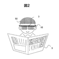
- FIG. 2 is a diagram illustrating a state in which the user 50 wears the HMD 10.
- the HMD 10 mainly includes an eyeglass-type frame 1, a transmissive display 2, an external camera 3, and a main controller 5.
- the frame 1 includes a pair of right and left temples 1a and 1b, a pair of left and right rims 1c and 1d into which the display 2 is fitted, and a bridge 1e connecting the rim 1c and the rim 1d.
- the user 50 wears the HMD 10 and reads a character string such as a newspaper or a book.
- a character string such as a newspaper or a book.
- the display 2 is placed in front of the eyes of the user 50. Then, the user visually recognizes the characters of the newspaper 9 and the book via the display 2.
- the external camera 3 is a camera equipped with a CCD or CMOS provided facing the outside of the frame 1 when the side facing the face of the user 50 in the frame 1 is defined as inside and the opposite side is defined as outside.
- the external camera 3 is provided on the bridge 1e substantially at the center of the frame 1 at a position and an orientation including the viewing area of the user 50 in the angle of view.
- the HMD 10 is characterized in that the character string captured by the external camera 3 is enlarged and AR-displayed to the user, thereby improving the visibility of the user.
- the main controller 5 is configured using a function for detecting a visual characteristic of the user 50 and compensating the visual characteristic, for example, a processor or a circuit for realizing a focus compensation function and an AR display function.
- a function for detecting a visual characteristic of the user 50 and compensating the visual characteristic for example, a processor or a circuit for realizing a focus compensation function and an AR display function.
- a configuration in which a general-purpose computer is used to execute software for realizing the above functions will be described as an example.
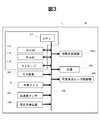
- FIG. 3 is a hardware configuration diagram of the HMD 10.
- the main control device 5 includes an input device 140, a measurement light detector 104, an acceleration sensor 164, a spatial light modulator 102e, an external camera 3, a light source 101, and a variable focus lens via a system bus 112.
- Each of the drivers 106 is connected to each other.
- Main controller 5 includes a CPU (Central Processing Unit) 111, a ROM (Read Only Memory) 113, a RAM (Random Access Memory) 114, an SSD (Solid Solid Drive) having a semiconductor memory such as a HDD (Hard Disk Drive) or a flash memory. Drive 115), which is connected to the system bus 112 and configured.
- CPU Central Processing Unit
- ROM Read Only Memory
- RAM Random Access Memory
- SSD Solid Solid Drive
- HDD Hard Disk Drive
- flash memory flash memory
- the input device 140 includes operation buttons and operation switches, and is an operation member that receives an operation such as an ON / OFF button of a main power supply of the HMD 10 or an enlargement ratio setting from the user 50. Other configurations will be described later.
- FIG. 4 is a diagram showing the configuration of the display optical system 102 and light propagation.
- FIG. 4 shows only a configuration for performing AR display on the right eye 50R of the HMD 10, but in practice, the configuration in FIG. The HMD 10 is also provided with the above configuration.
- a light source 101 and a measurement light detector 104 are provided on the right string 1b constituting the frame 1 of the HMD 10.
- the varifocal lens 103 is provided before the right eye 50R in the frame 1. Further, from the front right to the right string 1b of the frame 1, various optical elements constituting the display optical system 102 are provided. The optical element opposes the right eye 50R and the light guide 102b disposed from the position opposing the right eye 50R to the right chord 1b, and the light guide on the opposite side of the varifocal lens 103 across the light guide 102b.
- a first light beam 11a (see FIG. 5) for generating display light and a second light beam 11b (see FIG. 5) for generating measurement light for measuring visual characteristics are emitted from the light source 101,
- the light passes through the variable focus lens 103 via the display optical system 102 and enters the right eye 50R. That is, the light source 101, the display optical system 102, and the variable focus lens 103 are optically connected.
- the single light source 101 emits the first light beam 11a and the second light beam 11b, and the optical axes of the first light beam 11a and the second light beam 11b are substantially the same. Formed.
- light emitted from the right eye 50R enters the display optical system 102 via the variable focus lens 103, and the beam splitter 102c reflects the reflected light of the measurement light toward the measurement light detector 104. Let it.
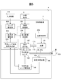
- FIG. 5 is a functional block diagram of the HMD 10.
- the main control device 5 includes an image processing unit 201, a user setting unit 202, an enlargement ratio calculation unit 203, a display image generation unit 204, a variable lens control signal generation unit 205, and a light source control unit 206. . These are configured in cooperation with hardware constituting the main control device 5 and software realizing the functions of the respective units.
- the light source 101 outputs the AR first light beam 11a in response to a blink signal from the light source control unit 206.
- the first light beam 11a becomes AR display light 12a having display information by the display optical system 102 based on the signal of the display image generation unit 204.
- the AR display light 12a is applied to the eye 50A of the user 50 via the varifocal lens 103. This allows the user 50 to view the AR display on which the virtual visual information is superimposed on the real space.
- the light source 101 outputs, in addition to the first light beam 11a, a second light beam 11b for measuring the visual characteristics of the user 50 wearing the HMD 10.
- the second light beam 11b is converted into a measuring light beam 12b having a predetermined light shape, for example, a perfect circular ring-shaped pattern by the display optical system 102.
- the ring-shaped shape has a focus position at, for example, a predetermined distance from the eye 50A of the user 50, and within a predetermined distance from the position, the ring diameter of the ring shape becomes closer to the user 50 as the user approaches the user 50.
- the measuring light 12b is directed to the eyes 50A of the user 50 as divergent light so as to gradually increase.
- the measurement light 12b is applied to the user's eye 50A via the varifocal lens 103. After the measurement light 12b enters the inside of the eye 50A, the measurement light 12b is reflected by the fundus of the eye 50A of the user 50, and the reflected light 13b reaches the beam splitter 102c via the light guide 102b and is reflected to detect the measurement light. Is detected by the detector 104.
- the variable lens control signal generation unit 205 estimates, for example, the refractive power of the eye 50A of the user 50 as a visual characteristic of the user 50 from the output signal of the measurement light detector 104, and generates a lens control signal according to the estimated refractive power. It is generated and output to the varifocal lens driver 106.
- the variable focus lens driver changes the refractive power of the variable focus lens 103 according to the lens control signal. It is desirable that the varifocal lens 103 can generate not only axially symmetric refractive power but also non-axially symmetric refractive power. Therefore, the varifocal lens 103 is composed of, for example, a spatial light modulator made of a transmissive liquid crystal or a liquid lens provided with an actuator (corresponding to the varifocal lens driver 106) so that the wavefront of a free-form surface can be controlled. You.
- the actuator for example, a linear electromagnetic actuator having a configuration in which a shaft (iron core) is made to protrude and retract in the axial direction by exciting / non-exciting a solenoid, and a displacement is applied to a piezoelectric element by applying a voltage. It is possible to use a piezoelectric actuator having a configuration for causing the piezoelectric actuator. Further, a shape memory alloy which is displaced by applying a current and applying heat may be used as the actuator.
- the size of the ring diameter of the measurement light 12b having the ring-shaped pattern used as the input light is determined by the beam splitter 102c in the HUD 10. It can be estimated from information such as how it was detected (changed) by the measurement light detector 104 via the interface.
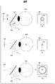
- FIG. 6 is a diagram illustrating a process of measuring the characteristics (visual characteristics) of the eyes 50A of the user 50 using the measurement light 12b.
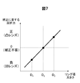
- FIG. 7 is a schematic diagram showing a necessary correction amount by the variable focus lens.
- the measurement light detector 104 is arranged at a predetermined distance from the position 11 conjugate with the focal plane 100 of the measurement light 12 b on the near side in the optical axis direction. With this arrangement, if the measurement light 12b is focused on the retina of the eye 50A of the user 50, the ring diameter D of the reflected light 13b applied to the measurement light detector 104 is larger than the ring diameter on the focal plane 100. , the predetermined size D 0 as shown in the upper part Fig.
- the reflected light 13b applied to the measurement light detector 104 focus to approach the eye 50A of the user 50, the ring diameter D 1 of the reflected light 13b is irradiated to the measuring photodetector 104 is smaller than a predetermined size D 0 of the foregoing.
- the focal point of the reflected light 13b is irradiated to the measuring photodetector 104 because away from the eyes 50A of the user 50, the ring diameter D 2 of the reflected light 13b is irradiated to the measuring photodetector 104 given the above-mentioned larger than the size D 0.
- the adjustment of the refractive power of the varifocal lens 103 can be performed using information on the size of the ring diameter of the reflected light 13b detected by the measurement light detector 104 as shown in FIG.
- the variable focus lens 103 is provided with a positive refractive power, in other words, the refractive power of the variable focus lens 103 so as to have the power of the convex lens.
- D 0 negative refractive power is smaller as compared with the adjusted so to have the refractive power of the variable focus lens 103 to comprise concave lens power in other words.
- the AR display light 12a is always adjusted by the variable focus lens 103 whose refractive power is adjusted regardless of the visual characteristics of the user 50.
- the eye can be focused on the retina of the eye 50A, and highly visible AR display can be performed.
- the focal plane of the AR display light 12a may be fixed at a predetermined distance, or may be adaptively set to the distance in the real space where the AR display light 12a is superimposed.
- a depth sensor for acquiring distance information may be added to the HMD 10, and the focal plane of the AR display light 12a and the measurement light 12b may be set based on the depth information from the depth sensor.
- the ring shape of the reflected light 13b detected by the measurement light detector 104 is an elliptical shape
- the size of the major axis and the minor axis direction of the ellipse and the major axis or the minor axis direction of the ellipse are detected. I do.
- the elliptical shape is obtained, for example, when the user 50 has astigmatism, because astigmatism due to astigmatism has occurred.
- each of the long axis and the short axis will be described with reference to FIG. Similarly to the above, the refractive power necessary for the correction is estimated, and then the refractive power of the entire lens surface area of the varifocal lens 103 is estimated.
- the inside of the lens surface area may be interpolated as a toroidal surface shape, and the refractive power of the entire lens surface area required for correction may be estimated.
- the method for measuring the visual characteristics of the user 50 is not limited to the above configuration, and any configuration may be used as long as the configuration can detect the focus state of light reflected by the fundus of the user's eye 50A.
- the measurement light does not have a pattern such as a ring shape, and an astigmatism detection optical system is provided as an optical system for detecting the reflection light of the user's eyes 50A, and the focus state of the reflection light 13b of the measurement light 12b is adjusted. It may be detected.
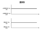
- FIG. 8 is a schematic diagram showing the irradiation timing of the AR display light 12a and the measurement light 12b.
- the measurement light 12b is turned off at the timing of irradiating the AR display light 12a to the eye 50A of the user 50, and conversely, the AR display is performed at the timing of irradiating the measurement light 12b to the eye 50A of the user 50.
- the light 12a is turned off.
- irradiation timing it is possible to avoid mutual information from interfering with each other. This is particularly effective when the AR display light 12a and the measurement light 12b use light beams of the same wavelength.
- the AR display light 12a may have a wavelength range of visible light
- the measurement light 12b may have a configuration of light beams having different wavelengths, such as a wavelength range of invisible light such as near infrared light.
- the light source 101 is configured to emit light beams having different wavelengths.
- the AR display light 12a and the measurement light 12b may be applied to the eye 50A of the user 50 at the same timing.
- the AR display light 12a can be generated by using a beam splitter 102c using a wavelength difference such as a dichroic mirror or a dichroic prism. It is possible to extract the reflected light 13b of the measurement light 12b while suppressing the interference.
- the HMD 10 is provided with an acceleration sensor 164, and the change in the movement is a fixed amount based on the output signal from the acceleration sensor 164. Is exceeded, the control of the refractive power of the varifocal lens 103 may be held for a predetermined period.
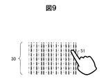
- FIG. 9 is a diagram illustrating an example of visually recognizing a real image in a real space.
- the finger 51 of the user 50 is recognized from the image captured by the external camera 3, and the position where the AR display is performed is determined based on the position of the finger 51.
- the user 50 specifies a predetermined portion of the character string 30 in the real space to be enlarged with the finger 51.
- the finger 51 is an example of a pointer.
- the HMD 10 further determines whether the character string is written vertically or horizontally from the image captured by the external camera 3.
- FIG. 10 is a schematic diagram of vertical writing and horizontal writing determination.
- FIG. 10A shows an example of vertical writing
- FIG. 10B shows an example of horizontal writing.
- String larger lateral space W T than in the longitudinal direction of the space W L as shown in FIG. 10A it is determined that vertical.
- the longitudinal direction of the space W L is larger than the lateral space W T as shown in FIG. 10B, the string is determined to horizontal.
- FIG. 11A is a diagram illustrating a setting example of the left area (vertical writing)
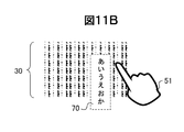
- FIG. 11B is a diagram illustrating an AR display example of the left area (vertical writing).
- the left area 60 at the position designated by the fingertip 51 is enlarged as shown in FIG. 11A.
- the reason for enlarging the area on the left side of the fingertip 51 is that the area on the right side of the fingertip 51 is hidden by the right finger of the user 50 or the palm of the right hand. This is because the effectiveness is lost. Therefore, in the case of vertical writing, the area on the right side of the fingertip 51 is not enlarged to improve the visibility of the user.
- the image processing unit 201 may learn the shapes of the right hand and the left hand in advance, and determine which finger is the finger captured in the image of the external camera 3.
- the area below the location designated by the fingertip 51 is set wider than the area above.
- the reason for this is that, in the case of vertical writing, the flow of character information flows from top to bottom, so that for the user 50, the character information in the upper region is more likely to be read, and the lower portion is more likely to be unread. This is because the character information in the area is considered to be more valuable. Therefore, by securing the lower area wider, the user 50 can increase the number of unread characters among the characters to be enlarged and displayed by a single pointing operation with a fingertip. Become.
- An image of the left area 60 of the fingertip 51 is extracted from the image information captured by the external camera 3 mounted on the HMD 10, and the character information of the left area 60 is expanded to the user as an AR display image 70 as shown in FIG. 11B. indicate.
- the background color of the AR display image 70 is, for example, the same as the background color of the character string in the real space and the background color of the character string displayed in the AR, the boundary between the AR space and the real space becomes ambiguous, and the visibility of the AR display information becomes visible. May deteriorate. Therefore, when the character string is enlarged and displayed by the AR display image, the background color of the character string displayed in the AR may be changed based on the information on the background color in the real space. For example, when the background color of the character string in the real space is white, the background color of the character string displayed in the AR is set to a background color other than white, such as gray or light blue.
- the image processing unit 201 extracts a region remaining after the character recognition processing on the image as a background region, analyzes the color tone of the background region (analyzes the intensity of each of the RGB signals), and displays a color different from the background color in AR. This is realized by selecting the background color.
- the present embodiment is different from this.
- the area on the right side of the fingertip may be enlarged and displayed to the user as an AR display image.
- the pointer may be replaced by a pen point held by the right hand instead of the index finger of the right hand, or a pen point held by the left hand instead of the index finger of the left hand. Further, another pen may be used instead of the pen.
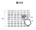
- FIG. 12A is a diagram showing a setting example of the upper region (horizontal writing)
- FIG. 12B is a diagram showing an AR display example of the upper region (horizontal writing).
- the HMD 10 may determine the type of language, not when it is determined that the character string is written vertically.
- text information advances from left to right.
- the range of the upper area 61 is set to be wider in the right side than in the left side in a language in which character information flows from left to right in consideration of the flow of characters from the same viewpoint as in the case of vertical writing. In a language in which character information flows from right to left, the area on the left side is set wider than on the right side.
- AR display enlargement ratio control
- a character string is enlarged and displayed by the AR display light 12a (corresponding to video light)
- the enlargement ratio is fixed, a character string having a relatively large size is enlarged more than necessary. Enlarging may be inadequate for character strings smaller than expected. It is desirable that the enlargement ratio can be adaptively enlarged according to the character size of the character string.
- the appearance differs depending on the visual acuity characteristics of the user 50. Therefore, changing the enlargement ratio according to the visual acuity characteristics of the user 50 also leads to improvement in visibility.
- the user 50 uses the input device 140 to input the character size after the enlargement by AR display in advance, and the input content is set in the user setting unit 202.
- the enlargement ratio calculation unit 203 appropriately calculates an enlargement ratio that is a set size, and the calculated enlargement ratio information is sent to the display image generation unit 204, and the calculated enlargement ratio is transmitted to the user 50 with the calculated enlargement ratio. Enlarge the display.
- the enlargement ratio calculation unit 203 acquires the character string information included in the image captured by the external camera 3 from the image processing unit 201 (dotted route in FIG. 5), and determines the character size included in the character string. The enlargement ratio is calculated based on the setting information and the setting information.
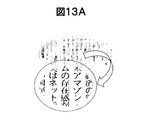
- FIGS. 13A and 13B are diagrams showing AR display examples. Regardless of the character size, such as a case of a relatively small character (see FIG. 13A) and a case of a relatively large character (see FIG. 13B), the user 50 always has a character of a preset size. Characters can be read in size, and the visibility of the user can be improved.
- the enlargement ratio calculation unit 203 acquires the lens control signal from the variable lens control signal generation unit 205, and calculates the enlargement ratio applied to the AR display, for example, according to the magnitude of the refractive power in FIG.
- FIG. 14 is a flowchart showing a flow of processing of the HMD 10 according to the present embodiment.
- the HMD 10 When the main power of the HMD 10 is turned on and the AR display processing starts, the processing flow shown in FIG. 14 starts.
- the HMD 10 describes an example in which the process using the measurement light 12b and the process based on the image captured by the external camera 3 start in parallel. , The processing using the measurement light 12b and the processing based on the image captured by the external camera 3 are alternately executed. In that case, the processing of steps S01 to S11 described later and the processing of steps S21 to S28 are executed alternately.
- Main controller 5 initializes the value i of the counter of the number of irradiations of measurement light 12b (S01), and emits second light beam 11b from light source 101.
- the user 50 is irradiated with the measurement light 12b (S02).
- the measurement light detector 104 detects the reflected light 13b formed on the fundus of the eye 50A of the user 50 (S03), and the variable lens control signal generation unit 205 measures the ring diameter Di (S04).
- the variable lens control signal generating unit 205 If the value i of the counter is less than the number of terms n to be added for obtaining the moving average value of the ring diameter Di (S05 / No), the variable lens control signal generating unit 205, the stack the value of the ring diameter D i in the RAM114 Then, the counter value i is incremented by 1 (S07), and the measurement light 12b is irradiated again (S02).
- variable lens control signal generating unit 205 If the number of terms n of the value i of the counter is added to determine a moving average value of the ring diameter D i (S05 / Yes), the variable lens control signal generating unit 205, a ring diameter D n calculated in the most recent stack It is is divided by the number of terms n by adding the ring diameter D 1 ⁇ D n-1 is, the average value D ave of the ring diameter D i (S08).
- Variable lens control signal generating unit 205 generates a lens control signal to determine the focus of the variable focus lens 103 according to the D ave (S09), and outputs the variable-focus lens driving unit 106 (S10).
- the varifocal lens driver 106 adjusts the refractive power of the varifocal lens 103 to a value corresponding to Dave . Accordingly, when the user 50 sees a character through the display 2, the focal length is adjusted according to the visual acuity characteristics of the user 50, the focus adjustment of the user 50 becomes easy, and the visibility is improved.
- the user 50 since adjusting the refractive power based on the moving average of the ring diameter D i, the user 50 in order to respond to changes in the refractive power, such frequent performs focus adjustment frequent suppresses to feel fatigue .
- the variable lens control signal generator 205 outputs the lens control signal to the magnification calculator 203.
- the enlargement ratio calculation unit 203 determines a character enlargement ratio according to the Dave (S11), and temporarily stores the character enlargement ratio in the RAM 114.
- Step S11 is omitted in an example in which the HMD 10 does not change the character size for performing AR display according to the result of the measurement light 12b but uses a preset character enlargement ratio (fixed value).
- the HMD 10 performs the AR display processing of steps S21 to S28 in parallel with the measurement processing of the visual acuity characteristics of the user 50 using the measurement light 12b of steps S01 to S11.
- the image processing unit 201 captures an image captured by the external camera 3 (S21), and performs character recognition processing on the image read by the image processing unit 201 (S22).
- the image processing unit 201 measures the interval between characters included in the image and determines whether the character information is written horizontally or vertically (S23). If the image processing unit 201 determines that the character is horizontal writing (S23 / Yes), it recognizes the character type and determines whether the language is a language in which character information flows from left to right or a language in which character information flows from right to left. (Determine the language type) (S24).
- the image processing unit 201 determines whether a pointer, for example, a fingertip or a pen is imaged in the image (S25). If the pointer is imaged (S25 / Yes), the position is output to the display image generation unit 204. The display image generation unit 204 determines the position as the AR display position (S26).
- the display image generation unit 204 reads the current character enlargement ratio determined in step S11 (S27), and based on the position determined in step S26, and in the case of horizontal writing, the direction in which the character information in the language determined in step S24 flows. Is set along the upper region 61, and the left region 60 is set downward in the case of vertical writing. A display object (visual information) for enlarging the character string in the left region 60 or the upper region 61 and performing AR display is set. It is generated (S28). Then, the light source control unit 206 causes the light source 101 to emit the first light beam 11a, the display image generation unit 204 causes the spatial light modulator 102e to generate video information indicating a display object, and the AR display light 12a is generated. You.
- the AR display light 12a passes through the projection lens 102d, the beam splitter 102c, the light guide 102b, the second reflection type hologram 102a2, the light guide 102b, the first reflection type hologram 102a1, and the variable focus lens 103. It is incident on 50A. Thereby, the user 50 visually recognizes the AR image.
- the HMD 10 ends a series of operations. If the termination condition is not satisfied (S30 / No), the process returns to step S01 and step S21 to continue a series of processes.
- the correction of the visual acuity and the AR display according to the visual acuity characteristics of the user 50 can be performed. Therefore, the visibility of the AR display superimposed on the external scenery can be improved while improving the visibility of the scenery of the real space visually recognized using the transmissive display 2.
- the AR display of the character string that will be visually recognized next will be displayed according to the direction in which the character information of vertical writing, horizontal writing from left to right, and horizontal writing from right to left flows. Since the priority can be given, the user 50 can easily read the character information.
- the present invention may improve the visibility of the scenery in the real space according to the visual characteristics of the user 50 by using the processing of steps S01 to S10.
- the character size of the AR display may be enlarged and displayed in accordance with the visual characteristics of the user 50 by using the processing of steps S21 to S28.
- a lens of the variable focus lens 103 is used for a real image in a relatively distant view of the real space, such as superimposing a building name on a real image of a real space in an AR display. Even if no adjustment is required, the character size displayed in AR is convenient when adjustment is required.
- variable focus lens 104 measurement light detector 105 : Variable lens control signal generator 106: Variable focus lens driver
Landscapes
- Physics & Mathematics (AREA)
- General Physics & Mathematics (AREA)
- Optics & Photonics (AREA)
Abstract
ヘッドマウントディスプレイは、第1の光ビーム及び第2の光ビームを発生させる光源と、第1の光ビームが入射しバーチャルな視覚情報を含む映像光を出射する表示光学系と、表示光学系から出射した映像光の光路上に設けられた可変焦点レンズ、及び可変焦点レンズの屈折力を変化させる可変焦点レンズ駆動器と、第2の光ビームがヘッドマウントディスプレイを装着したユーザの眼を反射した反射光を検出する測定光検出器と、主制御装置と、を備え、測定光検出器の出力に基づいて可変焦点レンズの屈折力を決定し、当該屈折力を実現させるためのレンズ制御信号を可変焦点レンズ駆動器に対して出力する可変レンズ制御信号生成部を備え、表示光学系から出射した映像光は、レンズ制御信号に応じて可変焦点レンズ駆動器が屈折力を調整した可変焦点レンズを透過してユーザの眼に入射する。
Description
本発明はヘッドマウントディスプレイに係り、特にユーザの視覚特性を考慮し、視認性の高いAR表示を行う技術に関する。
近年、実在する風景や視覚情報にバーチャルの視覚情報を重ねて表示する拡張現実(Augmented Reality(AR))といった表示技術が、スマートフォンやウェアラブルデバイスなどのAR表示デバイスの性能進化と相まって注目を集めている。ARは現実空間の視覚情報とバーチャルな視覚情報との組合せで実現されるため、ユーザはバーチャルな表示物体のみならず、常に現実空間の物体も合わせて見ていることになる。
一方、高齢化が世界中で急速に進展し、それに伴って老眼(老視)の高齢者が増えている。これらの方々は比較的遠くの距離にある現実空間の物体にピントは合うが、近くの距離にある現実空間の物体にはピントが合わなくなるといった事が生じる。そのため、ピント調整能力の補助が必要になり、AR表示中に例えば老眼鏡を掛けるといった動作が必要になる。但し、AR表示中にいちいち眼鏡を掛けたり外したりする動作は煩わしい。
そこで例えば特許文献1では「本発明の適応型眼鏡は、眼鏡フレームとその眼鏡フレームに搭載された第1と第2の電気的に調整可能なレンズを有する。1つの実施形態では、制御回路は、眼鏡を着用する人の1つの眼からその人により観察される物体までの距離を示す入力を受信し、そしてその入力に応答して第1と第2のレンズを調整するように構成される。」とあり、距離計を用いてユーザの眼から被写体までの距離を計測し、その距離に応じて可変焦点レンズの焦点を変える事でピント調整を行う内容が開示されている。
また特許文献2では「視度調節ができる事前補正画像を生成する補正画像データ生成方法、及び事前補正画像を表示する表示装置」に関する内容が開示されている。視度調節を可能とするため、事前補正画像を生成し、その生成方法として「光学系の補正関数で補正した事前補正画像データを生成する」との内容が記載されている。なお、補正関数の一例として「補正関数はデフォーカスの伝達関数の逆数である」との内容が記載されている。
例えば特許文献1の様にユーザの眼から被写体までの距離に応じたピント調整の場合、被写体の距離が同じ時のピント調整量は、どのユーザに対しても基本、同じ調整量となる。一方、一概に老眼といっても、その程度はユーザによって異なる。ピント調整量はユーザの視覚特性の個人差を考慮した量となる調整が望ましい。特許文献2においても、老眼のユーザにとって視認性が高くなる様に所定の補正関数で表示画像を事前に補正するものの、その補正量は基本、どのユーザに対しても同じであり、個人差を考慮した調整に関しては言及が無い。
本発明は、上記実情に鑑みてなされたものであり、ユーザの視覚特性を補償したAR表示が行えるヘッドマウントディスプレイを提供することを目的とする。
上記課題を解決するため、本発明では一例として、現実空間にバーチャルな視覚情報を重ねて表示するヘッドマウントディスプレイであって、前記ヘッドマウントディスプレイは、第1の光ビーム及び第1の光ビームとは異なる第2の光ビームを発生させる光源と、前記第1の光ビームが入射し、前記バーチャルな視覚情報を含む映像光を出射する表示光学系と、前記表示光学系から出射した前記映像光の光路上に設けられた可変焦点レンズ、及び前記可変焦点レンズの屈折力を変化させる可変焦点レンズ駆動器と、前記第2の光ビームが前記ヘッドマウントディスプレイを装着したユーザの眼を反射した反射光を検出する測定光検出器と、前記光源、前記可変焦点レンズ駆動器、及び前記測定光検出器の其々に接続された主制御装置と、を備え、前記主制御装置は、前記測定光検出器の出力に基づいて前記可変焦点レンズの屈折力を決定し、当該屈折力を実現するように前記可変焦点レンズを調整させるためのレンズ制御信号を生成し、前記可変焦点レンズ駆動器に対して出力する可変レンズ制御信号生成部を備え、前記表示光学系から出射した映像光は、前記レンズ制御信号に応じて前記可変焦点レンズ駆動器が屈折力を調整した前記可変焦点レンズを透過して前記ユーザの眼に入射する、ことを特徴とする。
本発明によれば、ユーザの視覚特性を補償したAR表示が行えるヘッドマウントディスプレイを提供する事ができる。上記した以外の課題、構成及び効果は、以下の実施形態の説明により明らかにされる。
以下、図面を用いて本発明の実施形態について説明する。全図を通じて同一の構成には同一の符号を付して重複説明を省略する。
<第1実施形態>
第1実施形態は、ユーザの視力を補償するための拡張表示(Augmented Reality(AR))機能を備えたHMD10に関する。図1は、HMD10の概要構成図である。図2は、HMD10をユーザ50が装着した状態を示す図である。
第1実施形態は、ユーザの視力を補償するための拡張表示(Augmented Reality(AR))機能を備えたHMD10に関する。図1は、HMD10の概要構成図である。図2は、HMD10をユーザ50が装着した状態を示す図である。
図1に示すようにHMD10は、主に眼鏡型のフレーム1、透過型のディスプレイ2、外界カメラ3、及び主制御装置5を備える。フレーム1は、左右一対のつる1a、1bと、ディスプレイ2が嵌め込まれる左右一対のリム1c,1dと、リム1cとリム1dとを繋ぐブリッジ1eと、を含む。
図2に示すように、ユーザ50はHMD10を装着して、新聞や本などの文字列を読む。ユーザ50がHMD10を装着すると、ディスプレイ2は、ユーザ50の眼の前に配置される。そして、ディスプレイ2を介して、新聞9や書籍の文字を視認する。
外界カメラ3は、フレーム1におけるユーザ50の顔と対向する側を内側、その反対側を外側と定義した場合に、フレーム1の外側に向けて設けられたCCDやCMOSを搭載したカメラである。外界カメラ3は、ユーザ50の視認領域を画角に含む位置及び向きでフレーム1の略中央のブリッジ1eに設けられる。
ユーザ50は老視などの影響により、近い距離にある文字列に焦点が合わず、また、ユーザ50の眼からある程度距離を離して文字を読もうとすると、文字が小さすぎるために認識するのが困難な状態を想定する。HMD10は、外界カメラ3が捉えた文字列を拡大してユーザにAR表示することで、ユーザの視認性を向上させる点に特徴がある。
主制御装置5は、ユーザ50の視覚特性を検出し、その視覚特性を補償するための機能、例えば焦点補償機能や、AR表示機能を実現するためのプロセッサやサーキットを用いて構成される。本実施形態では、汎用のコンピュータを用い、上記各機能を実現するソフトウェアを実行する構成を例に挙げて説明する。
図3は、HMD10のハードウェア構成図である。
図3に示すように、主制御装置5は、システムバス112を介して入力装置140、測定光検出器104、加速度センサ164、空間光変調器102e、外界カメラ3、光源101、及び可変焦点レンズ駆動器106の其々を接続して構成される。
主制御装置5は、CPU(Central Processing Unit)111、ROM(Read Only Memory)113、RAM(Random Access Memory)114、HDD(Hard Disk Drive)やフラッシュメモリ等の半導体メモリを備えたSSD(Solid State Drive)からなるストレージ115を含み、これがシステムバス112で接続されて構成される。
入力装置140は、操作ボタンや操作スイッチからなり、例えばHMD10の主電源のON/OFFボタンやユーザ50からの拡大率設定等の操作を受け付ける操作部材である。その他の構成については後述する。
図4は、表示光学系102の構成と光伝搬を示す図である。説明の便宜のため、図4ではHMD10のうち、右目50RにAR表示を行うための構成のみを示しているが、実際には、図4の構成を左右反転させ、左目にAR表示を行うための構成もHMD10は備えている。
HMD10のフレーム1を構成する右弦1bに光源101及び測定光検出器104を備える。またフレーム1における右目50Rの前に可変焦点レンズ103を備える。また、フレーム1の右前から右弦1bにかけて、表示光学系102を構成する各種光学素子を備える。光学素子は、右目50Rと対向し、かつ、右目50Rと対向する位置から右弦1bにかけて配置された導光体102bと、導光体102bを挟んで可変焦点レンズ103とは反対側における導光体102bの外面に配置された第1反射型ホログラム102a1、及び導光体102bの外面における右端に配置された第2反射型ホログラム102a2と、導光体102bよりも内側に、右弦1bの耳側(図中の上側)に向かって順に配置されたビームスプリッタ102c、投射レンズ102d、例えば透過型の液晶パネルで構成される空間光変調器102e、レンズ102fを含む。
光源101からは表示光を生成する第1の光ビーム11a(図5参照)と、視覚特性を測定するための測定光を生成する第2の光ビーム11b(図5参照)とが出射し、表示光学系102を介して可変焦点レンズ103を通過し、右目50Rに入射する。つまり、光源101から表示光学系102、可変焦点レンズ103は、光接続されている。また本例では単一の光源101が、第1の光ビーム11a及び第2の光ビーム11bを出射し、第1の光ビーム11a及び第2の光ビーム11bの光軸がほぼ同一になるように形成される。
また右目50Rからの出射光(可視光の反射光)は、可変焦点レンズ103を介して表示光学系102に入射し、ビームスプリッタ102cが測定光の反射光を測定光検出器104に向けて反射させる。
図5は、HMD10の機能ブロック図である。
図5に示すように、主制御装置5は、画像処理部201、ユーザ設定部202、拡大率算出部203、表示画像生成部204、可変レンズ制御信号生成部205、及び光源制御部206を含む。これらは主制御装置5を構成するハードウェアと各部の機能を実現するソフトウェアとが協働して構成される。
光源101は、光源制御部206からの点滅信号に応じてAR用の第1の光ビーム11aを出力する。第1の光ビーム11aは、表示画像生成部204の信号を元に表示光学系102によって表示情報を有するAR表示光12aとなる。
AR表示光12aは可変焦点レンズ103を介してユーザ50の目50Aに照射される。これによってユーザ50は、現実空間に対してバーチャルな視覚情報が重畳されたAR表示を視覚することができる。
本実施形態において、光源101は、第1の光ビーム11aに加えて、HMD10を装着したユーザ50の視覚特性を測定するための第2の光ビーム11bを出力する。第2の光ビーム11bは、表示光学系102によって所定の光形状、例えば真円のリング状のパターンを有する測定光12bとなる。また該リング状の形状は、例えばユーザ50の目50Aから所定の距離離れた位置にフォーカス位置を有し、その位置から所定の距離の範囲では、ユーザ50に近づくにつれて該リング形状のリング径が次第に大きくなる様、測定光12bは発散光としてユーザ50の目50Aに向かう。
その後、測定光12bは可変焦点レンズ103を介してユーザの目50Aに照射される。測定光12bは目50Aの内部に入射した後、ユーザ50の目50Aの眼底で反射され、その反射光13bが導光体102bを経由してビームスプリッタ102cに到達し、反射して測定光検出器104によって検出される。
可変レンズ制御信号生成部205は、測定光検出器104の出力信号からユーザ50の視覚特性として、例えばユーザ50の目50Aの屈折力を見積もり、見積もられた屈折力に応じてレンズ制御信号を生成し、可変焦点レンズ駆動器106に出力する。
可変焦点レンズ駆動器106は、レンズ制御信号に応じて可変焦点レンズ103の屈折力を変更する。なお可変焦点レンズ103は軸対称の屈折力のみならず非軸対称の屈折力を生成可能である事が望ましい。そのため可変焦点レンズ103は、自由曲面の波面制御が可能な様に、例えば透過型の液晶による空間光変調器、又はアクチュエータ(可変焦点レンズ駆動器106に相当)を備えた液体レンズ等で構成される。ここで、本実施形態では、アクチュエータとして、例えば、ソレノイドを励磁/非励磁することでシャフト(鉄心)を軸方向に出没させる構成のリニア電磁アクチュエータや、電圧を印加することで圧電素子に変位を生じさせる構成の圧電アクチュエータを用いることができる。また、電流を流して熱を加えることで変位する形状記憶合金をアクチュエータとして用いても良い。
測定光検出器104の出力信号からユーザの眼の屈折力を見積もる方法としては、入力光として用いたリング状のパターンを有する測定光12bのリング径の大きさが、HUD10内のビームスプリッタ102cを介して測定光検出器104でどの様に検出されたか(変化したか)といった情報から見積もる事ができる。
図6、図7を参照して視覚特性及び可変焦点レンズによる必要補正量について説明する。図6は、測定光12bを用いてユーザ50の目50Aの特性(視覚特性)を測定する処理を示す図である。図7は、可変焦点レンズによる必要補正量を示す概略図である。
図6に示すように、例えば測定光検出器104を測定光12bの焦点面100と共役な位置11から所定の距離だけ光軸方向手前側に配置する。この配置により、ユーザ50の目50Aの網膜に測定光12bが焦点を結んでいれば、測定光検出器104に照射される反射光13bのリング径Dは焦点面100でのリング径よりも大きく、図6上段に示すように所定の大きさD0となる。
一方、ユーザの視覚特性により、例えば測定光12bがユーザ50の目50Aの網膜よりも手前で焦点を結ぶ場合(図6の中段参照s)、測定光検出器104に照射される反射光13bの焦点はユーザ50の目50Aに近づくため、測定光検出器104に照射される反射光13bのリング径D1は前述の所定の大きさD0に比べて小さくなる。
また、例えばユーザ50の視覚特性によっては、測定光12bの焦点がユーザ50の目50Aの網膜よりも奥に焦点を持つ様な場合(図6の下段参照)も生じる。この場合は、測定光検出器104に照射される反射光13bの焦点がユーザ50の目50Aから遠ざかるため、測定光検出器104に照射される反射光13bのリング径D2は前述の所定の大きさD0に比べて大きくなる。
よって、例えば可変焦点レンズ103の屈折力の調整は、図7に示すように測定光検出器104によって検出された反射光13bのリング径の大きさの情報を用いて調整する事ができる。検出されたリング径が所定の大きさD0に比べて大きい場合は正の屈折力、言い換えれば凸レンズのパワーを備えるように可変焦点レンズ103の屈折力を持たせ、リング径が所定の大きさD0に比べて小さい場合は負の屈折力、言い換えれば凹レンズのパワーを備えるように可変焦点レンズ103の屈折力を持たせるように調整する。屈折力の大きさはリング径の大きさの関数として事前に学習しておく事で、屈折力を適応的に調整する事ができる。
またAR表示光12aの焦点面に測定光12bの焦点面を予め合わせておけば、ユーザ50の視覚特性によらず、屈折力が調整された可変焦点レンズ103によって、AR表示光12aを常にユーザの目50Aの網膜に焦点を結ぶことができ、視認性の高いAR表示が可能となる。
なお本実施形態において、AR表示光12aの焦点面は、所定の距離に固定しても良いし、又はAR表示光12aを重畳する現実空間の距離に適応的に設定しても良い。後者の場合は、HMD10に別途、距離情報を取得する深度センサを追加し、該深度センサからの深度情報を元にAR表示光12a及び測定光12bの焦点面を設定すれば良い。
本実施形態では、測定光検出器104によって検出される反射光13bのリング形状が楕円形状の場合、楕円の長軸及び短軸方向の径の大きさと、楕円の長軸又は短軸方向を検出する。楕円形状となるのは、例えばユーザ50が乱視の場合であり、乱視による非点収差が生じているためであるので、先ずは長軸及び短軸各々に対して前述の図7を用いた説明と同様に、補正に必要な屈折力を見積もり、その後、可変焦点レンズ103のレンズ面領域全面の屈折力を見積もる。例えば、長軸と短軸での屈折力の情報を用いて、トロイダル面形状としてレンズ面領域内を補間して、補正に必要なレンズ面領域全面の屈折力を見積もれば良い。
以上、測定光12bの光形状をリング状にし、リング形状の変化からユーザの眼の視覚特性を把握する方法を述べた。
ユーザ50の視覚特性の測定方法は上記構成に限定されず、ユーザの目50Aの眼底で反射した光のフォーカス状態を検出できる構成であれば、どの様な構成であっても構わない。例えば測定光はリング状などのパターンを持たず、ユーザの目50Aの反射光を検出する光学系として、非点収差系の検出光学系を備えて、測定光12bの反射光13bのフォーカス状態を検出してもよい。
図8は、AR表示光12aと測定光12bの照射タイミングを示した概略図である。例えば図8Aに示すように、ユーザ50の目50Aに対してAR表示光12aを照射するタイミングでは測定光12bを消灯し、逆に測定光12bをユーザ50の目50Aに照射するタイミングではAR表示光12aを消灯する。このような照射タイミングとする事で、お互いの情報が他方に干渉するのを避けることができる。これはAR表示光12aと測定光12bにて同じ波長の光ビームを使用する場合に特に有効となる。但し本実施形態では、AR表示光12aと測定光12bは同じ波長を用いる必要は必ずしも無い。
例えばAR表示光12aは可視光の波長域、測定光12bは近赤外などの不可視光の波長域といった具合に、互いに異なる波長の光ビームの構成としても良い。その場合、光源101は互いに異なる波長の光ビームを出射する構成となる。この場合、例えば図8Bに示すように、AR表示光12aと測定光12bをユーザ50の目50Aに同タイミングで照射しても良い。AR表示光12aと同タイミングで測定光12bをユーザ50の目50Aに照射しても、例えばダイクロミラーやダイクロプリズムなどの波長の違いを利用したビームスプリッタ102cを用いる事で、AR表示光12aの干渉を抑制して、測定光12bの反射光13bを抽出することが可能である。
(屈折力制御のホールド機能)
ユーザ50が現実空間において距離の異なる対象物を目まぐるしく切り替えて視覚している場合、ユーザ50の目50Aによる屈折力が目まぐるしく切り替わっていることになるが、その際に可変焦点レンズ103の屈折力を常に制御すると、かえってユーザ50にとっては視認性が劣化する恐れもある。そのためユーザ50が現実空間において距離の異なる対象物を目まぐるしく切り替えて視覚している場合は、可変焦点レンズ103の屈折力の制御を所定時間の間、ホールドしておいても良い。その様な場合は、ユーザ50の顔の向きが目まぐるしく変わっている可能性が高いので、例えば、HMD10に加速度センサ164を備え、加速度センサ164からの出力信号を元に、動きの変化が一定量を超えた場合は可変焦点レンズ103の屈折力の制御を所定期間、ホールドしても良い。
ユーザ50が現実空間において距離の異なる対象物を目まぐるしく切り替えて視覚している場合、ユーザ50の目50Aによる屈折力が目まぐるしく切り替わっていることになるが、その際に可変焦点レンズ103の屈折力を常に制御すると、かえってユーザ50にとっては視認性が劣化する恐れもある。そのためユーザ50が現実空間において距離の異なる対象物を目まぐるしく切り替えて視覚している場合は、可変焦点レンズ103の屈折力の制御を所定時間の間、ホールドしておいても良い。その様な場合は、ユーザ50の顔の向きが目まぐるしく変わっている可能性が高いので、例えば、HMD10に加速度センサ164を備え、加速度センサ164からの出力信号を元に、動きの変化が一定量を超えた場合は可変焦点レンズ103の屈折力の制御を所定期間、ホールドしても良い。
(AR表示:表示位置制御)
ユーザ50の視界にAR表示をする場合、ユーザ50の視界の妨げにならない位置にAR表示を行うことが好ましい。そこで下記では、文字列が縦書きか横書きかによって、AR表示(拡大表示)をする領域を変える例について説明する。図9は、現実空間の実像の視認例を示す図である。
ユーザ50の視界にAR表示をする場合、ユーザ50の視界の妨げにならない位置にAR表示を行うことが好ましい。そこで下記では、文字列が縦書きか横書きかによって、AR表示(拡大表示)をする領域を変える例について説明する。図9は、現実空間の実像の視認例を示す図である。
図9に示すように、外界カメラ3で撮像した画像から、ユーザ50の指51を認識し、この指51の位置を基準にAR表示を行う位置を決定する。図9では、ユーザ50が拡大したい実空間に有る文字列30の所定箇所を指51で指定する。指51は、ポインタの一例である。
更にHMD10は、外界カメラ3で捉えた画像から、文字列が縦書きなのか横書きなのかを判断する。
図10は、縦書き、横書き判断の概略図であり、図10Aは縦書き、図10Bは横書き例を示す。図10Aに示すように縦方向のスペースWLに比べて横方向のスペースWTが大きければ文字列は縦書きと判断する。また図10Bに示すように横方向のスペースWTに比べて縦方向のスペースWLが大きければ、文字列は横書きと判断する。
続いて、AR表示を行う所定領域を設定し、その所定領域に対してAR表示を行う例について説明する。図11Aは、左側領域の設定例を示す図(縦書き)であり、図11Bは、左側領域のAR表示例(縦書き)を示す図である。例えば前述の方法によって文字列が縦書きと判断された場合、図11Aに示すように指先51で指定した箇所の左側領域60を拡大する。指先51の左側の領域を拡大する理由は、指先51の右側の領域はユーザ50の右指や右手の掌などによって隠れてしまうため、文字情報があまり含まれておらず、文字拡大の効果の有効性が失われるためである。そこで、縦書きの場合、指先51の右側の領域は文字拡大しない事でユーザの視認性向上を図る。
画像処理部201は、事前に右手及び左手の形状を学習しておき、外界カメラ3の画像に撮像された指がどちらの手の指であるかを判断してもよい。
また左側領域60の範囲は、指先51が指定した箇所の上側よりも下側の領域をより広く設定する。この理由は、縦書きの場合、文字情報の流れは上から下方向に流れるため、ユーザ50にとっては上側の領域の文字情報は既読である可能性が高く、未読の可能性が高い下側の領域の文字情報の方が価値があると考えられるためである。そこで下側の領域をより広く確保する事で、ユーザ50は一回の指先による指定動作によって、拡大表示する文字のうち、未読の文字の文字数を増やすことができ、スムーズに読むことが可能となる。
HMD10に搭載された外界カメラ3が捉えた画像情報から、指先51の左側領域60の画像を抽出し、その左側領域60の文字情報を図11Bに示すようにAR表示像70として、ユーザに拡大表示する。
AR表示像70の背景色が、例えば実空間の文字列の背景とAR表示する文字列の背景色が同色の場合、実空間との境界が曖昧になってしまい、AR表示の情報に対する視認性が劣化する恐れがある。そこでAR表示像によって文字列を拡大表示する際、実空間の背景色の情報に基づいてAR表示する文字列の背景色を変更しても良い。例えば実空間の文字列の背景色が白色の場合、AR表示する文字列の背景色を灰色や水色など、白以外の背景色とする。この処理は画像処理部201が画像に対する文字認識処理後に残った領域を背景領域として抽出し、その背景領域の色調解析(RGB各信号の強度を解析)し、背景色とは異なる色をAR表示の背景色として選択することにより実現する。
以上、上記は右手の人差し指で指定した場合を想定していたため、これとは異なり、例えば左手の人差し指で指定した場合は、指先の右側の領域をAR表示像としてユーザに拡大表示すれば良い。また、ポインタは、右手の人差し指の代わりに右手で持ったペン先、又は左手の人差し指の代わりに左手で持ったペン先などで代用しても構わない。また、ペンの代わりに他のもので代用しても構わない。
図12Aは、上側領域の設定例を示す図(横書き)であり、図12Bは、上側領域のAR表示例(横書き)を示す図である。HMD10が、文字列が横書きと判断された場合は、縦書きと判断されたときにはない、言語の種類判定を行ってもよい。英語やドイツ語は左から右へと文字情報が進む。一方、アラビア語のように右から左へと文字方向が進む言語もある。よって、拡大するAR表示像をユーザ50が今着目している文字よりもより先の文字情報に基づいて生成しようとする場合、言語の種類によって、指先51よりも右か左のどちらに先の文字情報が掲載されているか異なる。
そこで、図12Aに示すように指先51で指定した箇所の上側領域61にある文字列を拡大するために、外界カメラ3が捉えた画像情報に対して文字認識を行い、文字の種類、例えばアルファベット、ペルシャ文字等を基に言語種類を決定する。そして、指先51の上側箇所の上側領域61の画像を抽出し、その上側領域61の情報を図12Bに示すようにAR表示像71として同様にユーザに拡大表示する。また、該上側領域61の範囲は縦書きの場合と同様の観点で、文字の流れを考慮して、左から右へと文字情報が流れる言語では、左側よりも右側の領域をより広く設定し、右から左へと文字情報が流れる言語では、右側よりも左側の領域をより広く設定する。
(AR表示:拡大率制御)
AR表示光12a(映像光に相当する)によって文字列を拡大表示する際、拡大率を固定してしまうと、比較的大きなサイズの文字列に対しては必要以上に拡大されてしまったり、また想定よりも小さなサイズの文字列に対しては拡大が不十分になる可能性がある。拡大率は文字列の文字サイズに応じて適応的に拡大できる事が望ましい。また、新聞や書籍に掲載された文字サイズが同じであっても、ユーザ50の視力特性によって見え方が異なる。よって、ユーザ50の視力特性に応じて拡大率を変更することも、視認性向上につながる。
AR表示光12a(映像光に相当する)によって文字列を拡大表示する際、拡大率を固定してしまうと、比較的大きなサイズの文字列に対しては必要以上に拡大されてしまったり、また想定よりも小さなサイズの文字列に対しては拡大が不十分になる可能性がある。拡大率は文字列の文字サイズに応じて適応的に拡大できる事が望ましい。また、新聞や書籍に掲載された文字サイズが同じであっても、ユーザ50の視力特性によって見え方が異なる。よって、ユーザ50の視力特性に応じて拡大率を変更することも、視認性向上につながる。
そこで、ユーザ50は入力装置140を用いてAR表示による拡大後の文字サイズを事前に入力し、その入力内容はユーザ設定部202に設定される。格納された設定情報に基づき、拡大率算出部203は設定サイズとなる拡大率を適宜算出し、その算出された拡大率情報は表示画像生成部204に送られ、算出した拡大率でユーザ50に拡大表示する。その際、拡大率算出部203は画像処理部201から外界カメラ3が撮像した画像に含まれている文字列情報を取得し(図5の点線ルート)、その文字列に含まれている文字サイズと上記設定情報とを基に拡大率を算出する。
図13A、図13BはAR表示例を示す図である。比較的小さな文字の場合(図13A参照)や、それよりも比較的大きな文字の場合(図13B参照)など、どの様な文字サイズであっても、ユーザ50は常に事前設定した大きさの文字サイズで文字を読むことが可能になり、ユーザの視認性向上が図れる。
また、家族でHMD10を共用する場合には、ユーザ50の視力特性が変わる。よって、ユーザ設定ではなく、測定光12bを用いた測定結果に応じて拡大率を変更してもよい。その際、拡大率算出部203は可変レンズ制御信号生成部205からレンズ制御信号を取得し、例えば図7の屈折力の大小に合わせてAR表示に適用する拡大率を算出する。
図14は、本実施形態に係るHMD10の処理の流れを示すフローチャートである。
HMD10は、主電源が投入され、AR表示処理が開始すると、図14に示す処理フローが開始する。本例では図8Bに示すように、HMD10は、測定光12bを用いた処理と、外界カメラ3で撮像した画像に基づく処理とが並行して開始する例について説明するが、図8Aによる処理では、測定光12bを用いた処理と、外界カメラ3で撮像した画像に基づく処理とが交互に実行される。その場合は、後述するステップS01~S11までの処理と、ステップS21~S28までの処理とが交互に実行される。
主制御装置5は、測定光12bの照射回数のカウンタの値iを初期化し(S01)、光源101から第2の光ビーム11bを出射する。ユーザ50には測定光12bが照射される(S02)。測定光検出器104は、ユーザ50の目50Aの眼底で結像した反射光13bを検出し(S03)、可変レンズ制御信号生成部205がリング径Diを計測する(S04)。
カウンタの値iがリング径Diの移動平均値を求めるために加算する項数n未満であれば(S05/No)、可変レンズ制御信号生成部205は、RAM114にリング径Diの値をスタックし(S06)、カウンタの値iを1インクリメントして(S07)、再び測定光12bの照射を行う(S02)。
カウンタの値iがリング径Diの移動平均値を求めるために加算する項数nであれば(S05/Yes)、可変レンズ制御信号生成部205は、直近で求めたリング径Dnとスタックされているリング径D1~Dn-1とを加算して項数nで除算することで、リング径Diの平均値Daveを求める(S08)。
可変レンズ制御信号生成部205は、Daveに応じて可変焦点レンズ103の焦点を決定するためのレンズ制御信号を生成し(S09)、可変焦点レンズ駆動器106に出力する(S10)。
可変焦点レンズ駆動器106は、可変焦点レンズ103の屈折力をDaveに応じた値に調整する。これにより、ユーザ50がディスプレイ2を透過して文字を視認する際に、ユーザ50の視力特性に応じて焦点距離を調整し、ユーザ50のピント調整が容易となり、視認性向上につながる。
また、リング径Diの移動平均に基づいて屈折力を調整するので、頻回な屈折力の変化に対応するためにユーザ50が頻回にピント調整を行い、疲労感を感じることを抑制する。
可変レンズ制御信号生成部205は、レンズ制御信号を拡大率算出部203に出力する。拡大率算出部203はレンズ制御信号を用いて、又はDaveを取得した場合は、これに応じた文字拡大率を決定し(S11)、RAM114に一次的に記憶する。HMD10が測定光12bによる結果に応じてAR表示を行う文字サイズを変更するのではなく、予め設定された文字拡大率(固定値)を用いる例では、ステップS11を省略する。
HMD10は、上記ステップS01~S11までの測定光12bを用いたユーザ50の視力特性の測定処理と並行して、ステップS21~S28までのAR表示処理を実行する。
外界カメラ3が撮像した画像を画像処理部201が取込み(S21)、画像処理部201が読み込んだ画像に対して文字認識処理を実行する(S22)。
画像処理部201は、画像に含まれている文字の間隔を計測し、文字情報が横書きであるか縦書きであるかを判定する(S23)。画像処理部201は、横書きであると判定すると(S23/Yes)、文字種類を認識し、左から右へ文字情報が流れる言語であるか、又は右から左へ文字情報が流れる言語であるかを決定(言語種類を決定)する(S24)。
更に画像処理部201は、画像中にポインタ、例えば指先やペン等が撮像されているかを判定する(S25)。ポインタが撮像されていれば(S25/Yes)、その位置を表示画像生成部204に出力する。表示画像生成部204は、その位置をAR表示位置として決定する(S26)。
表示画像生成部204は、ステップS11で決定された現在の文字拡大率を読込み(S27)、ステップS26で決定した位置を基準とし、横書きであればステップS24で決定した言語における文字情報が流れる方向に沿って上側領域61を、縦書きであれば下方向に左側領域60を設定し、この左側領域60又は上側領域61内の文字列を拡大してAR表示を行う表示オブジェクト(視覚情報)を生成する(S28)。そして光源制御部206は光源101に第1の光ビーム11aを射出させ、表示画像生成部204が空間光変調器102eに対して表示オブジェクトを示す映像情報を生成させ、AR表示光12aが生成される。AR表示光12aは、投射レンズ102d、ビームスプリッタ102c、導光体102b、第2反射型ホログラム102a2、導光体102b、第1反射型ホログラム102a1、可変焦点レンズ103を経由してユーザ50の目50Aに入射する。これにより、ユーザ50がAR像を視認する。
HMD10の主電源がOFFにされる等の終了条件を充足すると(S30/Yes)、HMD10は一連の動作を終了する。終了条件未充足であれば(S30/No)、ステップS01及びステップS21へ戻り、一連の処理を継続する。
本実施形態によれば、ユーザ50の視力特性に応じた視力の矯正とAR表示とが行える。そのため、透過型のディスプレイ2を用いて視認した現実空間の風景に対しての視認性を向上させつつ、その外界風景に重畳するAR表示の視認性も向上できる。
また現実空間の風景が文字情報の場合、縦書きや左から右への横書き、また右から左への横書きの文字情報の流れる方向に応じて、次に視認すると思われる文字列のAR表示を優先して行えるので、ユーザ50が文字情報を読みやすくなる。
上記実施形態は本発明を限定する趣旨ではなく、本発明には様々な変更例が含まれる。例えば、本発明は、上記ステップS01~S10までの処理を用いて、ユーザ50の視覚特性に応じて現実空間の風景の視認性を向上させてもよい。また、上記ステップS21~S28までの処理を用いて、AR表示の文字サイズをユーザ50の視覚特性に合わせて拡大表示してもよい。これは例えば、地図ナビゲーションシステムに本HMD10を用いる際に、現実空間のビルの実像にビル名をAR表示で重ねる等、現実空間の比較的遠景にある実像に対しては可変焦点レンズ103のレンズ調整が不要であってもAR表示される文字サイズは調整が必要な場合に便利である。
1 :フレーム
2 :ディスプレイ
3 :外界カメラ
5 :主制御装置
10 :HMD
11a :第1の光ビーム
11b :第2の光ビーム
12a :AR表示光
12b :測定光
13b :反射光
50A :目
50R :右目
102 :表示光学系
103 :可変焦点レンズ
104 :測定光検出器
105 :可変レンズ制御信号生成部
106 :可変焦点レンズ駆動器
2 :ディスプレイ
3 :外界カメラ
5 :主制御装置
10 :HMD
11a :第1の光ビーム
11b :第2の光ビーム
12a :AR表示光
12b :測定光
13b :反射光
50A :目
50R :右目
102 :表示光学系
103 :可変焦点レンズ
104 :測定光検出器
105 :可変レンズ制御信号生成部
106 :可変焦点レンズ駆動器
Claims (12)
- 現実空間にバーチャルな視覚情報を重ねて表示するヘッドマウントディスプレイであって、
前記ヘッドマウントディスプレイは、
第1の光ビーム及び第1の光ビームとは異なる第2の光ビームを発生させる光源と、
前記第1の光ビームが入射し、前記バーチャルな視覚情報を含む映像光を出射する表示光学系と、
前記表示光学系から出射した前記映像光の光路上に設けられた可変焦点レンズ、及び前記可変焦点レンズの屈折力を変化させる可変焦点レンズ駆動器と、
前記第2の光ビームが前記ヘッドマウントディスプレイを装着したユーザの眼を反射した反射光を検出する測定光検出器と、
前記光源、前記可変焦点レンズ駆動器、及び前記測定光検出器の其々に接続された主制御装置と、を備え、
前記主制御装置は、
前記測定光検出器の出力に基づいて前記可変焦点レンズの屈折力を決定し、当該屈折力を実現するように前記可変焦点レンズを調整させるためのレンズ制御信号を生成し、前記可変焦点レンズ駆動器に対して出力する可変レンズ制御信号生成部を備え、
前記表示光学系から出射した映像光は、前記レンズ制御信号に応じて前記可変焦点レンズ駆動器が屈折力を調整した前記可変焦点レンズを透過して前記ユーザの眼に入射する、
ことを特徴とするヘッドマウントディスプレイ。 - 請求項1記載のヘッドマウントディスプレイにおいて、
前記主制御装置に接続された外界カメラを更に備え、
前記主制御装置は、前記外界カメラが撮像した画像を処理する画像処理部と、
前記画像処理部の出力情報を基に前記バーチャルな視覚情報を生成し、前記表示光学系に前記視覚情報を出力する表示画像生成部と、を更に含む、
ことを特徴とするヘッドマウントディスプレイ。 - 請求項1記載のヘッドマウントディスプレイにおいて、
前記光源は、複数の波長域の光ビームを発生させ、前記第1の光ビームの波長域と前記第2の光ビームの波長域とは互いに異なる、
ことを特徴とするヘッドマウントディスプレイ。 - 請求項1記載のヘッドマウントディスプレイにおいて、
前記主制御装置は、前記光源の点滅を制御する光源制御部を更に含み、
前記光源制御部は、前記第1の光ビームの照射時には前記第2の光ビームを消灯させ、前記第2の光ビームの照射時には前記第1の光ビームを消灯させる光源制御信号を前記光源に出力する、
ことを特徴とするヘッドマウントディスプレイ。 - 請求項1記載のヘッドマウントディスプレイにおいて、
前記光源は、リング形状からなる前記第2の光ビームを照射し、
前記可変レンズ制御信号生成部は、前記測定光検出器からの出力を基に前記反射光のリング径を算出し、算出されたリング径に基づいて前記可変焦点レンズの屈折力を規定し、当該屈折力を実現させるためのレンズ制御信号を生成し、前記可変焦点レンズ駆動器に出力する、
ことを特徴とするヘッドマウントディスプレイ。 - 請求項2記載のヘッドマウントディスプレイにおいて、
前記画像処理部は、前記外界カメラが撮像した画像に、予め定められたポインタが撮像されているかを判断し、前記ポインタが示す前記画像上の位置を前記表示画像生成部に出力し、
前記表示画像生成部は、前記外界カメラが撮像した画像のうち、前記ポインタが示す位置を基準とする所定領域内の部分画像を拡大した前記視覚情報を生成する、
ことを特徴とするヘッドマウントディスプレイ。 - 請求項6記載のヘッドマウントディスプレイにおいて、
前記外界カメラが撮像した画像は、前記現実空間にある文字列を撮像した画像であり、
前記表示画像生成部は、前記ポインタが示す位置を基準とする所定領域内にある文字列を拡大した前記視覚情報を生成する、
ことを特徴とするヘッドマウントディスプレイ。 - 請求項7記載のヘッドマウントディスプレイにおいて、
前記主制御装置は、前記可変レンズ制御信号生成部が決定した前記可変焦点レンズの屈折力に基づいて、前記部分画像の拡大率を算出する拡大率算出部を更に備え、
前記表示画像生成部は、前記拡大率で前記所定領域内にある文字列を拡大した前記視覚情報を生成する、
ことを特徴とするヘッドマウントディスプレイ。 - 請求項7記載のヘッドマウントディスプレイにおいて、
前記主制御装置に接続された入力装置を更に備え、
前記主制御装置は、
前記入力装置から、拡大後の文字サイズを指定する操作を受け付けて、当該文字サイズを目標文字サイズとして設定するユーザ設定部と、
前記画像処理部から前記所定領域内にある文字列情報を取得し、当該文字列情報に含まれる文字サイズを前記目標文字サイズに近づけるための拡大率を算出する拡大率算出部と、を更に含み、
前記表示画像生成部は、前記拡大率で前記所定領域内にある文字列を拡大した前記視覚情報を生成する、
ことを特徴とするヘッドマウントディスプレイ。 - 請求項7記載のヘッドマウントディスプレイにおいて、
前記画像処理部は、前記文字列が縦書きであるか否かを判定し、かつ前記ポインタとして右手が含まれているか左手が含まれているかを判定し、
前記表示画像生成部は、前記文字列が縦書きであり、かつ前記ポインタとして右手が含まれている場合は、前記ポインタが示す位置の左側を拡大した前記視覚情報を生成し、前記文字列が縦書きであり、かつ前記ポインタとして左手が含まれている場合は、前記ポインタが示す位置の右側を拡大した前記視覚情報を生成する、
ことを特徴とするヘッドマウントディスプレイ。 - 請求項7記載のヘッドマウントディスプレイにおいて、
前記画像処理部は、前記文字列が横書きであるか否かを判定し、
前記表示画像生成部は、前記文字列が横書きである場合は、前記ポインタが示す位置の上側を拡大した前記視覚情報を生成する、
ことを特徴とするヘッドマウントディスプレイ。 - 請求項11記載のヘッドマウントディスプレイにおいて、
前記画像処理部は、前記文字列が横書きであると判定すると、更に当該文字列が左から右へと文字情報が流れる言語であるか又は右から左へと文字情報が流れる言語であるかを判定し、
前記表示画像生成部は、前記文字列が左から右へと文字情報が流れる言語である場合は、前記ポインタが示す位置の上側かつ当該位置よりも右側の文字列を拡大した前記視覚情報を生成し、前記文字列が右から左へと文字情報が流れる言語である場合は、前記ポインタが示す位置の上側かつ当該位置よりも左側の文字列を拡大した前記視覚情報を生成する、
ことを特徴とするヘッドマウントディスプレイ。
Priority Applications (1)
| Application Number | Priority Date | Filing Date | Title |
|---|---|---|---|
| PCT/JP2018/032429 WO2020044555A1 (ja) | 2018-08-31 | 2018-08-31 | ヘッドマウントディスプレイ |
Applications Claiming Priority (1)
| Application Number | Priority Date | Filing Date | Title |
|---|---|---|---|
| PCT/JP2018/032429 WO2020044555A1 (ja) | 2018-08-31 | 2018-08-31 | ヘッドマウントディスプレイ |
Publications (1)
| Publication Number | Publication Date |
|---|---|
| WO2020044555A1 true WO2020044555A1 (ja) | 2020-03-05 |
Family
ID=69644003
Family Applications (1)
| Application Number | Title | Priority Date | Filing Date |
|---|---|---|---|
| PCT/JP2018/032429 Ceased WO2020044555A1 (ja) | 2018-08-31 | 2018-08-31 | ヘッドマウントディスプレイ |
Country Status (1)
| Country | Link |
|---|---|
| WO (1) | WO2020044555A1 (ja) |
Citations (10)
| Publication number | Priority date | Publication date | Assignee | Title |
|---|---|---|---|---|
| JPH07128613A (ja) * | 1993-11-04 | 1995-05-19 | Matsushita Electric Ind Co Ltd | 頭部装着型映像表示装置 |
| JPH08166556A (ja) * | 1994-12-13 | 1996-06-25 | Olympus Optical Co Ltd | 映像表示装置 |
| JPH08286144A (ja) * | 1995-04-14 | 1996-11-01 | Canon Inc | 画像観察装置及びそれを用いた観察機器 |
| JP2007172251A (ja) * | 2005-12-21 | 2007-07-05 | Konica Minolta Photo Imaging Inc | 表示装置 |
| JP2014106698A (ja) * | 2012-11-27 | 2014-06-09 | Seiko Epson Corp | 表示装置、頭部装着型表示装置および表示装置の制御方法 |
| US20140177063A1 (en) * | 2012-12-21 | 2014-06-26 | Industrial Technology Research Institute | Virtual image display apparatus |
| US20150234188A1 (en) * | 2014-02-18 | 2015-08-20 | Aliphcom | Control of adaptive optics |
| WO2016203654A1 (ja) * | 2015-06-19 | 2016-12-22 | 日立マクセル株式会社 | ヘッドマウントディスプレイ装置およびそれを用いた視覚補助方法 |
| WO2018003205A1 (ja) * | 2016-06-27 | 2018-01-04 | 富士フイルム株式会社 | 映像表示機能付き眼鏡 |
| JP2018050904A (ja) * | 2016-09-28 | 2018-04-05 | 株式会社トプコン | 眼科装置 |
-
2018
- 2018-08-31 WO PCT/JP2018/032429 patent/WO2020044555A1/ja not_active Ceased
Patent Citations (10)
| Publication number | Priority date | Publication date | Assignee | Title |
|---|---|---|---|---|
| JPH07128613A (ja) * | 1993-11-04 | 1995-05-19 | Matsushita Electric Ind Co Ltd | 頭部装着型映像表示装置 |
| JPH08166556A (ja) * | 1994-12-13 | 1996-06-25 | Olympus Optical Co Ltd | 映像表示装置 |
| JPH08286144A (ja) * | 1995-04-14 | 1996-11-01 | Canon Inc | 画像観察装置及びそれを用いた観察機器 |
| JP2007172251A (ja) * | 2005-12-21 | 2007-07-05 | Konica Minolta Photo Imaging Inc | 表示装置 |
| JP2014106698A (ja) * | 2012-11-27 | 2014-06-09 | Seiko Epson Corp | 表示装置、頭部装着型表示装置および表示装置の制御方法 |
| US20140177063A1 (en) * | 2012-12-21 | 2014-06-26 | Industrial Technology Research Institute | Virtual image display apparatus |
| US20150234188A1 (en) * | 2014-02-18 | 2015-08-20 | Aliphcom | Control of adaptive optics |
| WO2016203654A1 (ja) * | 2015-06-19 | 2016-12-22 | 日立マクセル株式会社 | ヘッドマウントディスプレイ装置およびそれを用いた視覚補助方法 |
| WO2018003205A1 (ja) * | 2016-06-27 | 2018-01-04 | 富士フイルム株式会社 | 映像表示機能付き眼鏡 |
| JP2018050904A (ja) * | 2016-09-28 | 2018-04-05 | 株式会社トプコン | 眼科装置 |
Similar Documents
| Publication | Publication Date | Title |
|---|---|---|
| JP7679163B2 (ja) | ディスプレイとユーザの眼との間の位置合わせを決定するためのディスプレイシステムおよび方法 | |
| JP7710586B2 (ja) | ディスプレイとユーザの眼との間の位置合わせを決定するためのディスプレイシステムおよび方法 | |
| JP7200195B2 (ja) | 感覚式アイウェア | |
| JP7699254B2 (ja) | 左および右ディスプレイとユーザの眼との間の垂直整合を決定するためのディスプレイシステムおよび方法 | |
| US7784945B2 (en) | Display Apparatus, display method, display program, integrated circuit, goggle-type head-mounted display, vehicle, monocle, and stationary display | |
| CN107636514B (zh) | 头戴式显示装置和使用该装置的视觉辅助方法 | |
| US10031579B2 (en) | Automatic calibration for reflective lens | |
| US9028067B1 (en) | Relocated virtual retinal image method and system | |
| EP3470909B1 (en) | Image projection system and image projection method | |
| EP3330771A1 (en) | Display apparatus and method of displaying using focus and context displays | |
| JP6707823B2 (ja) | 表示装置、表示装置の制御方法、及び、プログラム | |
| KR20190130147A (ko) | 디스플레이 시스템들을 위한 깊이 기반 포비티드 렌더링 | |
| CN113940055A (zh) | 具有视场移动控制的成像设备 | |
| JP6707809B2 (ja) | 表示装置、表示装置の制御方法、及び、プログラム | |
| JP6349660B2 (ja) | 画像表示装置、画像表示方法、および画像表示プログラム | |
| US12273498B2 (en) | Control device | |
| US11743447B2 (en) | Gaze tracking apparatus and systems | |
| CN112204453B (zh) | 影像投射系统、影像投射装置、影像显示光衍射光学元件、器具以及影像投射方法 | |
| JP2024081406A (ja) | 画像処理装置及び方法、プログラム、記憶媒体 | |
| WO2016203844A1 (ja) | 情報処理装置、情報処理方法、およびプログラム | |
| JP2019008204A (ja) | ヘッドマウントディスプレイ装置 | |
| CN121857208A (zh) | 头戴设备的变焦方法、装置、设备及介质 |
Legal Events
| Date | Code | Title | Description |
|---|---|---|---|
| 121 | Ep: the epo has been informed by wipo that ep was designated in this application |
Ref document number: 18931548 Country of ref document: EP Kind code of ref document: A1 |
|
| NENP | Non-entry into the national phase |
Ref country code: DE |
|
| 122 | Ep: pct application non-entry in european phase |
Ref document number: 18931548 Country of ref document: EP Kind code of ref document: A1 |
|
| NENP | Non-entry into the national phase |
Ref country code: JP |