WO2020035993A1 - 制御装置、冷凍機、制御方法及び異常検出方法 - Google Patents
制御装置、冷凍機、制御方法及び異常検出方法 Download PDFInfo
- Publication number
- WO2020035993A1 WO2020035993A1 PCT/JP2019/024025 JP2019024025W WO2020035993A1 WO 2020035993 A1 WO2020035993 A1 WO 2020035993A1 JP 2019024025 W JP2019024025 W JP 2019024025W WO 2020035993 A1 WO2020035993 A1 WO 2020035993A1
- Authority
- WO
- WIPO (PCT)
- Prior art keywords
- compressors
- control device
- surging
- deviation
- compressor
- Prior art date
- Legal status (The legal status is an assumption and is not a legal conclusion. Google has not performed a legal analysis and makes no representation as to the accuracy of the status listed.)
- Ceased
Links
Images

Classifications
-
- F—MECHANICAL ENGINEERING; LIGHTING; HEATING; WEAPONS; BLASTING
- F25—REFRIGERATION OR COOLING; COMBINED HEATING AND REFRIGERATION SYSTEMS; HEAT PUMP SYSTEMS; MANUFACTURE OR STORAGE OF ICE; LIQUEFACTION SOLIDIFICATION OF GASES
- F25B—REFRIGERATION MACHINES, PLANTS OR SYSTEMS; COMBINED HEATING AND REFRIGERATION SYSTEMS; HEAT PUMP SYSTEMS
- F25B49/00—Arrangement or mounting of control or safety devices
- F25B49/005—Arrangement or mounting of control or safety devices of safety devices
-
- F—MECHANICAL ENGINEERING; LIGHTING; HEATING; WEAPONS; BLASTING
- F25—REFRIGERATION OR COOLING; COMBINED HEATING AND REFRIGERATION SYSTEMS; HEAT PUMP SYSTEMS; MANUFACTURE OR STORAGE OF ICE; LIQUEFACTION SOLIDIFICATION OF GASES
- F25B—REFRIGERATION MACHINES, PLANTS OR SYSTEMS; COMBINED HEATING AND REFRIGERATION SYSTEMS; HEAT PUMP SYSTEMS
- F25B49/00—Arrangement or mounting of control or safety devices
- F25B49/02—Arrangement or mounting of control or safety devices for compression type machines, plants or systems
-
- F—MECHANICAL ENGINEERING; LIGHTING; HEATING; WEAPONS; BLASTING
- F04—POSITIVE - DISPLACEMENT MACHINES FOR LIQUIDS; PUMPS FOR LIQUIDS OR ELASTIC FLUIDS
- F04D—NON-POSITIVE-DISPLACEMENT PUMPS
- F04D27/00—Control, e.g. regulation, of pumps, pumping installations or pumping systems specially adapted for elastic fluids
- F04D27/001—Testing thereof; Determination or simulation of flow characteristics; Stall or surge detection, e.g. condition monitoring
-
- F—MECHANICAL ENGINEERING; LIGHTING; HEATING; WEAPONS; BLASTING
- F04—POSITIVE - DISPLACEMENT MACHINES FOR LIQUIDS; PUMPS FOR LIQUIDS OR ELASTIC FLUIDS
- F04D—NON-POSITIVE-DISPLACEMENT PUMPS
- F04D27/00—Control, e.g. regulation, of pumps, pumping installations or pumping systems specially adapted for elastic fluids
- F04D27/02—Surge control
- F04D27/0269—Surge control by changing flow path between different stages or between a plurality of compressors; load distribution between compressors
-
- F—MECHANICAL ENGINEERING; LIGHTING; HEATING; WEAPONS; BLASTING
- F25—REFRIGERATION OR COOLING; COMBINED HEATING AND REFRIGERATION SYSTEMS; HEAT PUMP SYSTEMS; MANUFACTURE OR STORAGE OF ICE; LIQUEFACTION SOLIDIFICATION OF GASES
- F25B—REFRIGERATION MACHINES, PLANTS OR SYSTEMS; COMBINED HEATING AND REFRIGERATION SYSTEMS; HEAT PUMP SYSTEMS
- F25B1/00—Compression machines, plants or systems with non-reversible cycle
- F25B1/04—Compression machines, plants or systems with non-reversible cycle with compressor of rotary type
- F25B1/053—Compression machines, plants or systems with non-reversible cycle with compressor of rotary type of turbine type
-
- F—MECHANICAL ENGINEERING; LIGHTING; HEATING; WEAPONS; BLASTING
- F25—REFRIGERATION OR COOLING; COMBINED HEATING AND REFRIGERATION SYSTEMS; HEAT PUMP SYSTEMS; MANUFACTURE OR STORAGE OF ICE; LIQUEFACTION SOLIDIFICATION OF GASES
- F25B—REFRIGERATION MACHINES, PLANTS OR SYSTEMS; COMBINED HEATING AND REFRIGERATION SYSTEMS; HEAT PUMP SYSTEMS
- F25B41/00—Fluid-circulation arrangements
- F25B41/20—Disposition of valves, e.g. of on-off valves or flow control valves
-
- F—MECHANICAL ENGINEERING; LIGHTING; HEATING; WEAPONS; BLASTING
- F25—REFRIGERATION OR COOLING; COMBINED HEATING AND REFRIGERATION SYSTEMS; HEAT PUMP SYSTEMS; MANUFACTURE OR STORAGE OF ICE; LIQUEFACTION SOLIDIFICATION OF GASES
- F25B—REFRIGERATION MACHINES, PLANTS OR SYSTEMS; COMBINED HEATING AND REFRIGERATION SYSTEMS; HEAT PUMP SYSTEMS
- F25B41/00—Fluid-circulation arrangements
- F25B41/30—Expansion means; Dispositions thereof
- F25B41/31—Expansion valves
-
- H—ELECTRICITY
- H02—GENERATION; CONVERSION OR DISTRIBUTION OF ELECTRIC POWER
- H02P—CONTROL OR REGULATION OF ELECTRIC MOTORS, ELECTRIC GENERATORS OR DYNAMO-ELECTRIC CONVERTERS; CONTROLLING TRANSFORMERS, REACTORS OR CHOKE COILS
- H02P5/00—Arrangements specially adapted for regulating or controlling the speed or torque of two or more electric motors
- H02P5/46—Arrangements specially adapted for regulating or controlling the speed or torque of two or more electric motors for speed regulation of two or more dynamo-electric motors in relation to one another
-
- F—MECHANICAL ENGINEERING; LIGHTING; HEATING; WEAPONS; BLASTING
- F25—REFRIGERATION OR COOLING; COMBINED HEATING AND REFRIGERATION SYSTEMS; HEAT PUMP SYSTEMS; MANUFACTURE OR STORAGE OF ICE; LIQUEFACTION SOLIDIFICATION OF GASES
- F25B—REFRIGERATION MACHINES, PLANTS OR SYSTEMS; COMBINED HEATING AND REFRIGERATION SYSTEMS; HEAT PUMP SYSTEMS
- F25B2339/00—Details of evaporators; Details of condensers
- F25B2339/04—Details of condensers
- F25B2339/047—Water-cooled condensers
-
- F—MECHANICAL ENGINEERING; LIGHTING; HEATING; WEAPONS; BLASTING
- F25—REFRIGERATION OR COOLING; COMBINED HEATING AND REFRIGERATION SYSTEMS; HEAT PUMP SYSTEMS; MANUFACTURE OR STORAGE OF ICE; LIQUEFACTION SOLIDIFICATION OF GASES
- F25B—REFRIGERATION MACHINES, PLANTS OR SYSTEMS; COMBINED HEATING AND REFRIGERATION SYSTEMS; HEAT PUMP SYSTEMS
- F25B2400/00—Component parts or details not otherwise provided for in this subclass
- F25B2400/04—Refrigeration circuit bypassing means
- F25B2400/0403—Refrigeration circuit bypassing means for condensers
-
- F—MECHANICAL ENGINEERING; LIGHTING; HEATING; WEAPONS; BLASTING
- F25—REFRIGERATION OR COOLING; COMBINED HEATING AND REFRIGERATION SYSTEMS; HEAT PUMP SYSTEMS; MANUFACTURE OR STORAGE OF ICE; LIQUEFACTION SOLIDIFICATION OF GASES
- F25B—REFRIGERATION MACHINES, PLANTS OR SYSTEMS; COMBINED HEATING AND REFRIGERATION SYSTEMS; HEAT PUMP SYSTEMS
- F25B2400/00—Component parts or details not otherwise provided for in this subclass
- F25B2400/06—Several compression cycles arranged in parallel
-
- F—MECHANICAL ENGINEERING; LIGHTING; HEATING; WEAPONS; BLASTING
- F25—REFRIGERATION OR COOLING; COMBINED HEATING AND REFRIGERATION SYSTEMS; HEAT PUMP SYSTEMS; MANUFACTURE OR STORAGE OF ICE; LIQUEFACTION SOLIDIFICATION OF GASES
- F25B—REFRIGERATION MACHINES, PLANTS OR SYSTEMS; COMBINED HEATING AND REFRIGERATION SYSTEMS; HEAT PUMP SYSTEMS
- F25B25/00—Machines, plants or systems, using a combination of modes of operation covered by two or more of the groups F25B1/00 - F25B23/00
- F25B25/005—Machines, plants or systems, using a combination of modes of operation covered by two or more of the groups F25B1/00 - F25B23/00 using primary and secondary systems
-
- F—MECHANICAL ENGINEERING; LIGHTING; HEATING; WEAPONS; BLASTING
- F25—REFRIGERATION OR COOLING; COMBINED HEATING AND REFRIGERATION SYSTEMS; HEAT PUMP SYSTEMS; MANUFACTURE OR STORAGE OF ICE; LIQUEFACTION SOLIDIFICATION OF GASES
- F25B—REFRIGERATION MACHINES, PLANTS OR SYSTEMS; COMBINED HEATING AND REFRIGERATION SYSTEMS; HEAT PUMP SYSTEMS
- F25B2500/00—Problems to be solved
- F25B2500/06—Damage
-
- F—MECHANICAL ENGINEERING; LIGHTING; HEATING; WEAPONS; BLASTING
- F25—REFRIGERATION OR COOLING; COMBINED HEATING AND REFRIGERATION SYSTEMS; HEAT PUMP SYSTEMS; MANUFACTURE OR STORAGE OF ICE; LIQUEFACTION SOLIDIFICATION OF GASES
- F25B—REFRIGERATION MACHINES, PLANTS OR SYSTEMS; COMBINED HEATING AND REFRIGERATION SYSTEMS; HEAT PUMP SYSTEMS
- F25B2600/00—Control issues
- F25B2600/02—Compressor control
- F25B2600/026—Compressor control by controlling unloaders
- F25B2600/0261—Compressor control by controlling unloaders external to the compressor
-
- F—MECHANICAL ENGINEERING; LIGHTING; HEATING; WEAPONS; BLASTING
- F25—REFRIGERATION OR COOLING; COMBINED HEATING AND REFRIGERATION SYSTEMS; HEAT PUMP SYSTEMS; MANUFACTURE OR STORAGE OF ICE; LIQUEFACTION SOLIDIFICATION OF GASES
- F25B—REFRIGERATION MACHINES, PLANTS OR SYSTEMS; COMBINED HEATING AND REFRIGERATION SYSTEMS; HEAT PUMP SYSTEMS
- F25B2600/00—Control issues
- F25B2600/25—Control of valves
- F25B2600/2501—Bypass valves
-
- F—MECHANICAL ENGINEERING; LIGHTING; HEATING; WEAPONS; BLASTING
- F25—REFRIGERATION OR COOLING; COMBINED HEATING AND REFRIGERATION SYSTEMS; HEAT PUMP SYSTEMS; MANUFACTURE OR STORAGE OF ICE; LIQUEFACTION SOLIDIFICATION OF GASES
- F25B—REFRIGERATION MACHINES, PLANTS OR SYSTEMS; COMBINED HEATING AND REFRIGERATION SYSTEMS; HEAT PUMP SYSTEMS
- F25B2600/00—Control issues
- F25B2600/25—Control of valves
- F25B2600/2513—Expansion valves
-
- F—MECHANICAL ENGINEERING; LIGHTING; HEATING; WEAPONS; BLASTING
- F25—REFRIGERATION OR COOLING; COMBINED HEATING AND REFRIGERATION SYSTEMS; HEAT PUMP SYSTEMS; MANUFACTURE OR STORAGE OF ICE; LIQUEFACTION SOLIDIFICATION OF GASES
- F25B—REFRIGERATION MACHINES, PLANTS OR SYSTEMS; COMBINED HEATING AND REFRIGERATION SYSTEMS; HEAT PUMP SYSTEMS
- F25B2700/00—Sensing or detecting of parameters; Sensors therefor
- F25B2700/15—Power, e.g. by voltage or current
- F25B2700/151—Power, e.g. by voltage or current of the compressor motor
-
- F—MECHANICAL ENGINEERING; LIGHTING; HEATING; WEAPONS; BLASTING
- F25—REFRIGERATION OR COOLING; COMBINED HEATING AND REFRIGERATION SYSTEMS; HEAT PUMP SYSTEMS; MANUFACTURE OR STORAGE OF ICE; LIQUEFACTION SOLIDIFICATION OF GASES
- F25B—REFRIGERATION MACHINES, PLANTS OR SYSTEMS; COMBINED HEATING AND REFRIGERATION SYSTEMS; HEAT PUMP SYSTEMS
- F25B2700/00—Sensing or detecting of parameters; Sensors therefor
- F25B2700/19—Pressures
- F25B2700/197—Pressures of the evaporator
-
- F—MECHANICAL ENGINEERING; LIGHTING; HEATING; WEAPONS; BLASTING
- F25—REFRIGERATION OR COOLING; COMBINED HEATING AND REFRIGERATION SYSTEMS; HEAT PUMP SYSTEMS; MANUFACTURE OR STORAGE OF ICE; LIQUEFACTION SOLIDIFICATION OF GASES
- F25B—REFRIGERATION MACHINES, PLANTS OR SYSTEMS; COMBINED HEATING AND REFRIGERATION SYSTEMS; HEAT PUMP SYSTEMS
- F25B2700/00—Sensing or detecting of parameters; Sensors therefor
- F25B2700/21—Temperatures
- F25B2700/2116—Temperatures of a condenser
- F25B2700/21163—Temperatures of a condenser of the refrigerant at the outlet of the condenser
-
- F—MECHANICAL ENGINEERING; LIGHTING; HEATING; WEAPONS; BLASTING
- F25—REFRIGERATION OR COOLING; COMBINED HEATING AND REFRIGERATION SYSTEMS; HEAT PUMP SYSTEMS; MANUFACTURE OR STORAGE OF ICE; LIQUEFACTION SOLIDIFICATION OF GASES
- F25B—REFRIGERATION MACHINES, PLANTS OR SYSTEMS; COMBINED HEATING AND REFRIGERATION SYSTEMS; HEAT PUMP SYSTEMS
- F25B2700/00—Sensing or detecting of parameters; Sensors therefor
- F25B2700/21—Temperatures
- F25B2700/2117—Temperatures of an evaporator
- F25B2700/21171—Temperatures of an evaporator of the fluid cooled by the evaporator
- F25B2700/21172—Temperatures of an evaporator of the fluid cooled by the evaporator at the inlet
-
- F—MECHANICAL ENGINEERING; LIGHTING; HEATING; WEAPONS; BLASTING
- F25—REFRIGERATION OR COOLING; COMBINED HEATING AND REFRIGERATION SYSTEMS; HEAT PUMP SYSTEMS; MANUFACTURE OR STORAGE OF ICE; LIQUEFACTION SOLIDIFICATION OF GASES
- F25B—REFRIGERATION MACHINES, PLANTS OR SYSTEMS; COMBINED HEATING AND REFRIGERATION SYSTEMS; HEAT PUMP SYSTEMS
- F25B2700/00—Sensing or detecting of parameters; Sensors therefor
- F25B2700/21—Temperatures
- F25B2700/2117—Temperatures of an evaporator
- F25B2700/21171—Temperatures of an evaporator of the fluid cooled by the evaporator
- F25B2700/21173—Temperatures of an evaporator of the fluid cooled by the evaporator at the outlet
-
- F—MECHANICAL ENGINEERING; LIGHTING; HEATING; WEAPONS; BLASTING
- F25—REFRIGERATION OR COOLING; COMBINED HEATING AND REFRIGERATION SYSTEMS; HEAT PUMP SYSTEMS; MANUFACTURE OR STORAGE OF ICE; LIQUEFACTION SOLIDIFICATION OF GASES
- F25B—REFRIGERATION MACHINES, PLANTS OR SYSTEMS; COMBINED HEATING AND REFRIGERATION SYSTEMS; HEAT PUMP SYSTEMS
- F25B49/00—Arrangement or mounting of control or safety devices
- F25B49/02—Arrangement or mounting of control or safety devices for compression type machines, plants or systems
- F25B49/022—Compressor control arrangements
Definitions
- the present invention relates to a control device, a refrigerator, a control method, and an abnormality detection method.
- This application claims priority based on Japanese Patent Application No. 2018-152256 for which it applied to Japan on August 13, 2018, and uses the content here.
- the refrigerant flow rate in the compressor is related to the current of the motor driving the compressor (hereinafter sometimes simply referred to as the compressor current value, etc.). For example, when there is a large difference between the current values of the two compressors, surging may have occurred in one of the compressors. If it is determined that surging has occurred in one of the compressors, a gas-phase refrigerant flows into the hot gas bypass that connects the discharge side and the suction side of the compressor, thereby increasing the compressor air volume and suppressing surging. Execute the protection operation.
- Patent Document 1 discloses a surging detection device that determines that surging has occurred when the rate of change in the operating current of an electric motor that drives a compressor falls outside an allowable range.
- the present invention provides a control device, a refrigerator, a control method, and an abnormality detection method that can solve the above-described problems.
- a control device for a refrigerator including a plurality of compressors connected in parallel, wherein a deviation of a current value flowing through each motor driving each of the plurality of compressors, Based on the air volumes of the plurality of compressors and the operating points indicated by the compression ratios, the occurrence of surging and the occurrence of droplet suction are detected.
- the control device when the deviation of the current value is equal to or more than a predetermined threshold, and the operating point indicates that the air volume is smaller than a predetermined reference, the plurality of compressors It is determined that the surging has occurred partially.
- the refrigerator includes a bypass pipe that connects a discharge side and a suction side of the plurality of compressors, and a bypass valve provided in the bypass pipe, and the control device includes: When the occurrence of the surging is detected, control for opening the bypass valve is performed.
- the control device when the state in which the deviation of the current value is equal to or greater than a predetermined threshold continues even after a predetermined time has elapsed since the occurrence of the surging is detected, Stop the control to open the bypass valve.
- the control device when the deviation of the current value is equal to or greater than a predetermined threshold, and the operating point indicates that the air volume is larger than a predetermined reference, It is determined that the suction of the droplets from the evaporator of the refrigerator is partially generated.
- the control device when the control device detects the occurrence of the suction of the droplet, the current operation is maintained until the deviation of the current value becomes less than a predetermined threshold.
- the refrigerator when the deviation of the current value does not become less than a predetermined threshold value even when a predetermined time has elapsed after detecting the occurrence of the droplet suction, the refrigerator The opening degree of the expansion valve provided in is reduced.
- a control device for a refrigerator including a plurality of compressors connected in parallel, wherein a deviation of a current value flowing through each motor driving each of the plurality of compressors is a predetermined value. If the operating point indicated by the air volume and the compression ratio of the plurality of compressors is smaller than a predetermined reference, the surging has occurred in a part of the plurality of compressors. Is determined.
- a control device for a refrigerator including a plurality of compressors connected in parallel, wherein a deviation of a current value flowing through each motor driving each of the plurality of compressors is a predetermined value.
- a refrigerator including a plurality of compressors connected in parallel, comprising: the control device according to any one of the above.
- a method for controlling a refrigerator including a plurality of compressors connected in parallel, wherein a current value flowing through each motor driving each of the plurality of compressors is obtained, Calculate the operating point indicated by the air volume and the compression ratio of the plurality of compressors, based on the deviation of the plurality of current values and the operating point, detect the occurrence of surging or droplet suction, and determine the occurrence of the surging. If detected, a predetermined surging protection operation is performed, and if the suction of the droplet is detected, the current operation state is maintained.
- a method for detecting an abnormality in a refrigerator including a plurality of compressors connected in parallel, wherein a current value flowing through each of the motors driving each of the plurality of compressors is acquired.
- a method for detecting an abnormality in a refrigerator including a plurality of compressors connected in parallel, wherein a current value flowing through each of the motors driving each of the plurality of compressors is acquired.
- the detection accuracy of surging can be increased, and unnecessary activation of surging protection control can be prevented.
- FIG. 7 is a diagram illustrating an abnormality detection process according to an embodiment of the present invention.
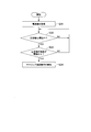
- 5 is a flowchart illustrating an example of abnormality detection processing and control performed when an abnormality is detected by the control device according to the embodiment of the present invention.
- 9 is a flowchart of surging determination and protection operation performed by a conventional control device.
- FIG. 7 is a diagram showing a relationship between a bypass valve control by a conventional control device and a current value flowing through an electric motor.
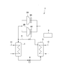
- FIG. 1 is a schematic configuration diagram illustrating an example of a refrigerator according to an embodiment of the present invention.
- the refrigerator 1 according to the present embodiment includes compressors 2A and 2B, a condenser 3, an expansion valve 4, an evaporator 5, a bypass pipe 6, a bypass pipe 6, and a compressor 2A, 2B connected in parallel.
- a valve 7 and a control device 8 are provided.
- the compressors 2A and 2B, the condenser 3, the expansion valve 4, and the evaporator 5 are connected to form a refrigerant circuit.
- two compressors 2A and 2B are connected in parallel. However, if a plurality of compressors are connected in parallel, the number of compressors is three or more. You may. A configuration may be adopted in which a plurality of compressors connected in series are connected in parallel with a plurality of compressors connected in series. In the present embodiment, one bypass pipe 6 is provided for the two compressors 2A and 2B, but a configuration in which the bypass pipe 6 is provided for each of the compressors 2A and 2B may be adopted.
- the compressors 2A and 2B compress the refrigerant and discharge the high-temperature and high-pressure refrigerant.
- Vane 9A, 9B is provided in the suction side of compressor 2A, 2B, respectively.
- the vanes 9 ⁇ / b> A and 9 ⁇ / b> B are controlled by the control device 8 and adjust the amount of refrigerant air flowing from the evaporator 5 to the compressor 2.
- Each of the compressors 2A and 2B is connected to an electric motor (not shown), and is driven by each electric motor.
- the control device 8 controls the number of rotations of the compressors 2A and 2B (number of rotations of the electric motors) by controlling the current of each electric motor, and supplies the refrigerant according to the load to the refrigerant circuit.
- the compressor 2 may be referred to as the compressor 2.
- the vanes 9A and 9B may be described as the vane 9.
- the current of the motor driving the compressor 2A is a current value Ia
- the current of the motor driving the compressor 2B is a current value Ib.
- the refrigerant discharged from the compressors 2A and 2B is supplied to the condenser 3.
- the condenser 3 condenses the high-temperature and high-pressure refrigerant.
- a pipe 11 is connected to the condenser 3, and cooling water is supplied to the pipe 11 from a cooling tower or the like.
- the refrigerant exchanges heat with the cooling water flowing through the pipe 11.
- the refrigerant condenses by radiating heat to the cooling water.
- the refrigerant condensed by the condenser 3 is decompressed by the expansion valve 4.
- the reduced-pressure low-pressure refrigerant is supplied to the evaporator 5.
- the evaporator 5 evaporates the low-pressure refrigerant.
- a pipe 12 is connected to the evaporator 5, and cold water is supplied to the pipe 12 from the load side.
- the refrigerant exchanges heat with cold water flowing through the pipe 12.
- the refrigerant cools the chilled water supplied to the load side and vaporizes by absorbing heat from the chilled water.
- the vaporized gas-phase refrigerant is sucked into the compressors 2A and 2B, and is compressed again by the compressors 2A and 2B.
- the subsequent flow of the refrigerant is as described above.
- the refrigerant thus circulates through the refrigerant circuit.
- the bypass pipe 6 is a refrigerant pipe connecting the discharge side and the suction side of the compressor 2. Specifically, one end of the bypass pipe 6 is connected to the discharge side of the compressor 2 and the upstream side of the refrigerant flow of the condenser 3, and the other end is provided on the suction side of the compressor 2. Connected to the gas phase portion of the evaporator 5 (the space where the gas phase refrigerant exists). That is, the bypass pipe 6 is formed so as to bypass the flow path of the condenser 3, the expansion valve 4, and the evaporator 5 through which the refrigerant discharged from the compressor 2 flows.
- the bypass pipe 6 is provided with a bypass valve 7 for adjusting the flow rate of the refrigerant flowing through the bypass pipe 6.
- the bypass valve 7 is an adjustment valve whose opening can be adjusted, and the control device 8 controls the opening of the bypass valve 7.
- the bypass valve 7 When the bypass valve 7 is opened, the gas-phase refrigerant discharged from the compressor 2 passes through the gas-phase portion of the evaporator 5 via the bypass pipe 6 and is supplied to the suction side of the compressor 2. That is, when the bypass valve 7 is opened and the amount of the refrigerant flowing through the bypass pipe 6 is increased, the amount of the gas-phase refrigerant supplied to the compressor 2 can be increased.
- the bypass pipe 6 is also called a hot gas bypass
- the bypass valve 7 is also called a hot gas bypass valve.
- ⁇ Surging in the compressor 2 occurs due to a decrease in the flow rate of the refrigerant flowing through the compressor 2.
- the bypass valve 7 is opened, and the gas-phase refrigerant discharged from the compressor 2 is supplied to the suction side of the compressor 2 via the bypass pipe 6.
- This control is called a surging protection operation.
- the bypass valve 7 will be described as a flow control valve, but the bypass valve 7 may simply be an on-off valve.
- a large difference may occur in the refrigerant air volume between the compressors 2A and 2B.
- the refrigerant air volume of the compressor 2A is sufficiently large and the refrigerant air volume of the compressor 2B is smaller than a predetermined value.
- surging may occur in the compressor 2B having a small refrigerant air flow.
- the difference in the amount of refrigerant air between the compressors 2A and 2B appears as a difference between the current value Ia of the motor driving the compressor 2A and the current value Ib of the motor driving the compressor 2B.
- the current value Ib of the compressor 2B whose air volume has decreased decreases.
- the fact that the difference between the current value Ia and the current value Ib is equal to or greater than a predetermined threshold does not necessarily indicate that surging has occurred.
- the liquid level is not always horizontal and uniform, and the liquid level may be uneven or wavy.
- the flow of the gas-phase refrigerant supplied to the compressor 2B grabs the liquid level surface of the evaporator 5, so that the liquid-phase refrigerant is scattered.
- the scattered liquid-phase refrigerant is mixed with the gas-phase refrigerant and carried, and a phenomenon occurs in which more liquid-phase refrigerant is supplied to the compressor 2B than in the compressor 2A.
- suction of droplets from the evaporator 5 occurs.
- the liquid level on the compressor 2A side is relatively low, and it is assumed that the refrigerant supplied to the compressor 2A is mainly a gas-phase refrigerant. Then, in the compressor 2A, no droplet suction occurs and the current value Ia does not increase. As described above, in the parallel refrigerator, droplet suction may occur only in some of the compressors. Even in such a situation, the deviation between the current values Ia and Ib flowing through the electric motors of the compressors 2A and 2B becomes large, and the deviation between the current values Ia and Ib may be equal to or larger than a predetermined threshold. If this phenomenon is determined as surging and a surging protection operation is performed, there is a possibility that the suction of droplets in the compressor 2B will be promoted. The reason will be described below.
- the other end of the bypass pipe 6 is connected to the gas phase side of the evaporator 5.
- the bypass valve 7 is opened by the surging protection operation to guide the gas-phase refrigerant discharged from the compressor 2 to the bypass pipe 6, the amount of refrigerant flowing through the evaporator 5 increases.
- the flow rate of the refrigerant increases, the amount of the liquid-phase refrigerant transported to the compressor 2 together with the gas-phase refrigerant increases.
- the flow rate of the refrigerant passing through the gas phase portion of the evaporator 5 increases, so that the amount of the liquid-phase refrigerant transferred to the compressor 2B also increases, and the suction of droplets is promoted. Since it is desirable for the compressor 2 to suck the gas-phase refrigerant, if the surging protection operation is performed when the suction of droplets occurs, the situation for the compressor 2 will be worsened (increase of the liquid-phase refrigerant).
- control device 8 of the present embodiment determines the operating point of the compressor 2 during operation in addition to the deviation of the current value of the compressor 2 by using a characteristic curve of the compressor 2 (pressure ratio-air volume). By comparing the operation state of the compressor 2 with the curve (curve), it is determined whether surging has occurred or whether droplet suction has occurred.
- ammeter a and ammeter b measure the current values Ia and Ib of the electric motor.
- various sensors (not shown) exemplified below are provided.
- thermometer for measuring the inlet temperature of the cold water flowing through the pipe 12 of the evaporator 5
- thermometer second sensor
- a flow rate for measuring the flow rate of the cold water
- a pressure gauge for measuring the pressure of the refrigerant in the evaporator 5
- a thermometer for measuring the temperature of the refrigerant on the upstream side of the refrigerant flow of the expansion valve 4, and the like.
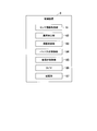
- FIG. 2 is a block diagram illustrating an example of a control device according to an embodiment of the present invention.
- the control device 8 is a computer device such as a microcomputer, for example.
- the control device 8 is connected to an ammeter a, an ammeter b, and first to fifth sensors (not shown).
- the control device 8 includes a sensor information acquisition unit 81, an abnormality detection unit 82, a protection control unit 83, a bypass valve control unit 84, an expansion valve control unit 85, a timer 86, a storage unit 87.
- the control device 8 performs various controls related to the refrigerator 1.
- the control device 8 describes an abnormality detection process of the compressor 2 and a function related to control when an abnormality is detected, and a description of other functions is omitted. I do.
- the sensor information acquisition unit 81 acquires a measurement value (sensor information) measured by each sensor from the ammeter a, the ammeter b, and the first to fifth sensors.
- the abnormality detection unit 82 detects an abnormal operation state occurring in the compressors 2A and 2B using the sensor information acquired by the sensor information acquisition unit 81.
- the abnormal operating state is surging and droplet suction.
- the abnormality detection unit 82 determines the compressors 2A and 2B based on the deviation between the current values Ia and Ib and the operating point of the compressor 2 calculated using the first to fifth sensors. In either case, it is detected that surging or droplet suction has occurred.
- the protection control unit 83 executes control according to the operation state, returns the operation state of the compressor 2 to a normal state, and Control is performed to prevent failure of the device.
- the bypass valve controller 84 adjusts the opening of the bypass valve 7. For example, when the abnormality detection unit 82 detects the occurrence of surging, the bypass valve control unit 84 performs control to open the bypass valve 7 based on an instruction from the protection control unit 83.
- the expansion valve control unit 85 adjusts the opening of the expansion valve 4. For example, when the abnormality detection unit 82 detects the occurrence of the suction of the droplet, the expansion valve control unit 85 performs control to close the expansion valve 4 based on an instruction from the protection control unit 83.
- the timer 86 measures time.
- the storage unit 87 stores various types of information such as the sensor information acquired by the sensor information acquisition unit 81 and a threshold used to determine whether or not the vehicle is in an abnormal operation state. Sometimes.
- the currents Ia and Ib indicate the operating states of the compressors 2A and 2B.
- the compression capacity of the compressor 2 increases, and when the current decreases, the compression capacity of the compressor 2 decreases.
- the compression capacity is low and the current value Ib is low because the flow rate of the refrigerant is small. Therefore, when surging occurs in one of the compressors 2, the deviation between the current values Ia and Ib increases. However, as in the case where a droplet is sucked in the compressor 2B, the deviation may increase as the current value Ib increases.
- the abnormality detection unit 82 detects an abnormal operation state of the compressor 2 using the characteristic curve of the compressor 2 in addition to the current values Ia and Ib.
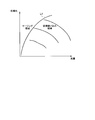
- FIG. 3 is a diagram illustrating an abnormality detection process according to an embodiment of the present invention.
- the abnormality detection performed by the abnormality detection unit 82 using the characteristic curve of the compressor 2 will be described with reference to FIG.
- FIG. 3 illustrates a characteristic curve L1 of the compression ratio-air volume of the compressor 2.
- the vertical axis of the graph in FIG. 3 is the compression ratio of the compressor 2, and the horizontal axis is the refrigerant air volume.
- the characteristic curve L1 indicates an operating point that is a boundary between surging and droplet suction in the relationship between the compression ratio of the compressor 2 and the refrigerant air volume.
- the characteristic curve L1 is calculated by performing a verification experiment or the like in advance for each compressor 2 and registered in the storage unit 87.
- Surging is an abnormal operation state that occurs when the amount of refrigerant air in the compressor 2 decreases.
- the operating point of the compressor 2 is in a relationship between the compression ratio and the air volume included in the left region of the characteristic curve L1, that is, when the air volume of the refrigerant is small, the possibility of occurrence of surging increases.
- the area on the left side of the characteristic curve L1 is called a surging area.
- Droplet suction is an abnormal operation state that is likely to occur when the refrigerant air volume is large.
- the refrigerant air volume is small, scattering of the liquid-phase refrigerant hardly occurs in the evaporator 5, and since the air volume is small, the liquid-phase refrigerant is also difficult to be carried. Therefore, the amount of the liquid-phase refrigerant sucked into the compressor 2 is also reduced.
- the operating point of the compressor 2 is in a relationship between the compression ratio and the air volume included in the area on the right side of the characteristic curve L1, that is, when the refrigerant air volume is large, there is a high possibility that droplet suction will occur.
- the area on the right side of the characteristic curve L1 is called a droplet suction area.
- the function ⁇ is registered in the storage unit 87.
- the function ⁇ is obtained by inputting the inlet and outlet temperatures of the chilled water cooled by the evaporator 5, the flow rate of the chilled water, the refrigerant pressure of the evaporator 5, and the refrigerant temperature on the upstream side of the expansion valve 4. It is a function that outputs the air volume.
- the abnormality detection unit 82 inputs the sensor information measured by the first sensor to the fifth sensor to the function ⁇ , and acquires the compression ratio of the compressor 2 and the refrigerant airflow output by the function ⁇ .
- the abnormality detector 82 compares the current operating point of the compressor 2 indicated by the compression ratio and the refrigerant flow rate based on the function ⁇ with the characteristic curve L1, and determines whether the operating point of the compressor 2 belongs to the surging region or not. It is determined whether it belongs to the drop suction area.
- the abnormality detection unit 82 determines whether the abnormality is detected in one of the compressors 2A and 2B. It is determined that surging has occurred.
- the threshold value ⁇ is a threshold value for determining that the compressor 2 is in an abnormal operation state, and is a value confirmed in advance by a verification experiment or the like.
- the abnormality detection unit 82 determines which of the compressors 2A and 2B It is determined that droplet suction has occurred.
- the protection control unit 83 corrects the abnormal operation state of the compressor 2 and performs control to protect the compressor 2 from a failure or the like.
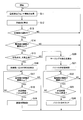
- FIG. 4 is a flowchart illustrating an example of abnormality detection processing and control at the time of abnormality detection by the control device according to the embodiment of the present invention.
- the sensor information acquisition unit 81 acquires sensor information such as a current value (Step S11). Specifically, the sensor information acquisition unit 81 acquires the current values Ia and Ib measured by the ammeter a and the ammeter b. The sensor information acquisition unit 81 acquires measurement values measured by the first to fifth sensors. The sensor information acquiring unit 81 continues acquiring these sensor information at predetermined time intervals.
- the abnormality detection unit 82 calculates an operating point (step S12). Specifically, the abnormality detection unit 82 is configured to output the chilled water inlet temperature, the chilled water outlet temperature, the chilled water flow rate, the refrigerant pressure at the evaporator 5, the refrigerant temperature at the evaporator 5 outlet, and the expansion valve 4 obtained by the sensor information obtaining unit 81. Based on the refrigerant temperature on the upstream side and the function ⁇ stored in the storage unit 87, the refrigerant flow rate and the compression ratio of the compressor 2 are calculated.
- control device 8 determines whether the compressor 2 is operating (step S13). When the compressor 2 is operating (step S13; Yes), the processing after step S14 is performed. When the compressor 2 is not operating (Step S13; No), the processing from Step S11 is repeated.
- the abnormality detection unit 82 determines whether or not the absolute value (
- the processing from Step S11 is repeated.
- the abnormality detection unit 82 determines whether the operating point calculated in Step S12 is on the large air volume side (Step S12). S15). Specifically, the abnormality detecting unit 82 determines which side of the characteristic curve L1 (FIG.
- the abnormality detection unit 82 determines that the operating point is not on the large air volume side.
- the abnormality detection unit 82 determines that the operating point is on the large air volume side.
- the abnormality detecting unit 82 detects the occurrence of the suction of the droplet (Step S16). In this case, it is estimated that droplet suction has occurred in any of the compressors 2.
- the control device 8 controls steps S17 to S19 described below.
- Step S15 When it is determined that the operating point is not on the large air volume side (Step S15; No), the abnormality detection unit 82 detects the occurrence of surging (Step S20). In this case, it is estimated that surging has occurred in any of the compressors 2.
- the control device 8 (protection control unit 83) controls Steps S21 to S24 described below.
- the protection control unit 83 performs the follow-up observation until a predetermined time elapses. Specifically, the protection control unit 83 determines, for example, at a predetermined time interval, whether or not the state in which the absolute value of the deviation between the current values Ia and Ib acquired by the sensor information acquisition unit 81 is equal to or larger than the threshold ⁇ is continued. A determination is made (step S17). When the absolute value of the deviation between the current values Ia and Ib is less than the threshold value ⁇ (Step S17; No), the protection control unit 83 determines that the droplet suction operation state in the compressor 2 has been eliminated. Since the abnormal operating state has been eliminated, the control device 8 repeats the processing from step S11.
- the protection control unit 83 refers to the timer 86 and detects that the abnormality detection unit 82 has caused the suction of the droplet. It is determined whether or not a predetermined time T1 has elapsed from (step S18). For example, the predetermined time T1 is set to a time required for the chilled water to become stable when the chilled water becomes unstable due to disturbance or the like. If the predetermined time T1 has not elapsed (step S18; No), the processing after step S17 is repeated.
- Step S18 If the predetermined time T1 has elapsed (Step S18; Yes), the fact that the suction of liquid droplets continues even after the predetermined time T1 has elapsed indicates that the air volume is excessive, so the protection control unit 83 sets the expansion valve
- the controller 85 is instructed to control the expansion valve 4 to close.
- the expansion valve controller 85 controls the expansion valve 4 to close (step S19).
- the opening degree of the expansion valve 4 is set in a range in which the suction of the droplets is suppressed and the influence on the operation state and load of the refrigerator 1 is sufficiently small.
- As the degree of opening of the expansion valve 4 a value determined in advance by experiments or the like is applied.
- the protection control unit 83 performs the same determination as in step S17 even after reducing the opening of the expansion valve 4, and when the absolute value of the deviation between the current values Ia and Ib returns to less than the threshold ⁇ , the protection control unit 83 opens the expansion valve 4. Return the degree to the original degree.
- the process of controlling the expansion valve 4 to close in step S19 is not essential.
- the protection control unit 83 may continue the follow-up observation (maintaining the current operation state while monitoring the deviation between the current values Ia and Ib) until the droplet suction state is suppressed. For example, when changing the opening of the expansion valve 4 has a strong effect on the operating state of the refrigerator 1, the follow-up observation may be continued. Alternatively, when the absolute value of the difference between the current values Ia and Ib does not return to less than the threshold value ⁇ , the protection control unit 83 may notify an alarm or the like instead of controlling the expansion valve 4 to close.
- an operation state in which droplet suction occurs occurs due to disturbance or the like, and is often resolved when a transient state is stabilized by waiting for a certain time.
- steps S16 to S19 when the control of the expansion valve 4 is not performed, steps S16 to S18
- the operation state in which the liquid droplet is sucked is eliminated without performing unnecessary control and deteriorating the situation. can do. Erroneous detection of surging can be prevented, and unnecessary opening control of the bypass valve 7 can be prevented.
- the protection control unit 83 performs control to forcibly open the bypass valve 7 (step S21). Specifically, the protection control unit 83 instructs the bypass valve control unit 84 to increase, for example, the opening of the bypass valve 7 to a predetermined value.
- the bypass valve control unit 84 increases the opening of the bypass valve 7 (for example, fully opens).
- the diameter of the bypass pipe 6 is designed so that surging can be eliminated when the bypass valve 7 is fully opened. Therefore, if the opening degree of the bypass valve 7 is set to 100% according to an instruction from the protection control unit 83, the air volume increases, and surging generated in one of the compressors 2A and 2B is eliminated.
- the protection control unit 83 continues to maintain the state where the absolute value of the deviation between the current values Ia and Ib acquired by the sensor information acquisition unit 81 is equal to or larger than the threshold value ⁇ . It is determined whether or not it has been performed (step S22). When the absolute value of the difference between the current values Ia and Ib is smaller than the threshold value ⁇ (Step S22; No), the protection control unit 83 determines that surging in the compressor 2 has been eliminated. Since the abnormal operating state has been eliminated, the control device 8 repeats the processing from step S11.
- the protection control unit 83 refers to the timer 86 and determines whether the abnormality detection unit 82 has detected occurrence of surging. It is determined whether the time T2 has elapsed (step S23). As the predetermined time T2, a time required for eliminating surging confirmed in an experiment or the like is set. If the predetermined time T2 has not elapsed (step S23; No), the processing after step S22 is repeated.
- Step S23 If the predetermined time T2 has elapsed (Step S23; Yes), it is considered that an abnormality other than surging such as a failure of a sensor such as the ammeter a has occurred, so the protection control unit 83 clears the opening of the bypass valve 7 ( Step S24). Clearing the opening of the bypass valve 7 means returning to the opening immediately before performing the forcible opening control in step S21. This means that if surging has occurred, surging should be eliminated by the forcible opening control of the bypass valve 7 (designed as such), but surging will not be eliminated. It is considered that another abnormality has occurred, and in that case, it is not appropriate to continue the state in which the opening degree of the bypass valve 7 is large.
- the opening of the bypass valve 7 is controlled according to a predetermined rule even during normal operation, and is set to a value corresponding to, for example, the operating point of the compressor 2.
- the protection control unit 83 controls the opening of the bypass valve 7 to this value.
- the protection control unit 83 may notify an alarm or the like indicating that a sensor failure or the like is suspected, in addition to the process of clearing the bypass valve 7.
- a surging protection operation is performed to quickly eliminate the occurrence of surging. Further, it is possible to detect a situation where an abnormality other than surging is suspected.
- the process shown in FIG. 4 is repeatedly executed at a predetermined control cycle while the compressor 2 is operating.
- FIG. 5 is a flowchart of surging determination and protection operation by the conventional control device.
- the control device 8 ′ determines whether or not the absolute value (
- the processing from Step S22 is repeated.
- the absolute value of the difference between the current values Ia and Ib is equal to or larger than the threshold value ⁇ (Step S33; Yes)
- the surging protection operation is started because there is a possibility that surging has occurred in the compressor 2 (S34).
- the control device 8 ' controls the opening of the bypass valve 7. Thereafter, the control device 8 'continues the surging protection operation until the absolute value of the difference between the current values Ia and Ib becomes less than the threshold value ⁇ , for example.
- FIG. 6 is a diagram showing a relationship between a bypass valve control by a conventional control device and a current value flowing through an electric motor.
- Each of the graphs 61 to 67 in FIG. 6 shows a transition of a state quantity measured when a disturbance occurs during the operation of the refrigerator 1 and a control quantity (valve opening and the like) output by the control device 8 '. .
- the vertical axis of the graph of FIG. 6 indicates the magnitude of the state amount or the control amount, and the horizontal axis indicates the passage of time.
- Graph 61 shows the cold water flow rate.
- a graph 62 shows a current value Ib of the motor driving the compressor 2B
- a graph 63 shows a current value Ia of the motor driving the compressor 2A.
- Graph 64 shows the opening of vane 9 (vanes 9A and 9B), and graph 65 shows the opening of bypass valve 7.
- Graph 66 shows the cold water inlet temperature, and graph 67 shows the cold water outlet temperature.
- the graph 68 shows the current limit value imposed on the current values Ia and Ib.
- the control device 8 'performs control to close the vane 9 when the current values Ia and Ib exceed the current limit value. When the opening of the vane 9 decreases, the current values Ia and Ib also decrease.
- the control device 8 ′ forcibly closes the vane 9 (graph 64), and forcibly opens the bypass valve 7 when the difference between the current values Ia and Ib becomes equal to or larger than the threshold ⁇ (graph 65). ) Perform control. Thereafter, due to the decrease in the current value Ib, the control device 8 'temporarily stops the surging protection operation. When the bypass valve 7 is fully closed by stopping the surging protection operation, the load on the motor increases. As the load increases, the current values Ia and Ib both increase (e3a, e3b).
- the control device 8 'forcibly opens the bypass valve 7.
- the bypass valve 7 is opened and the gas-phase refrigerant is sucked into the compressor 2 via the bypass pipe 6 and the evaporator 5, the suction of the droplets in the compressor 2B is promoted by the increase in the air volume.
- the current value Ib maintains a high value, and the deviation between the current value Ia and the current value Ib does not return to a state smaller than the threshold ⁇ (e6).
- ⁇ e6
- the suction of the droplets in the compressor 2B is a transient phenomenon that occurs due to the transient fluctuation of the cooling water flowing through the pipe 12 or the cooling water flowing through the pipe 11.
- the suction of the liquid drops is stopped, and the deviation between the current value Ia and the current value Ib also returns to a specified value (less than the threshold value ⁇ ).
- the suction of the droplet is detected at the time t1 without performing the erroneous surging detection at the time t1 by the processing of the flowchart described in FIG. Then, after detecting the suction of the droplet, the control device 8 continues the follow-up observation. Eventually, if the operation state of the refrigerator 1 (the state of the cold water or the cooling water) becomes stable, the suction of the droplets of the compressor 2B stops, and the continuous operation can be performed without stopping the refrigerator 1. In addition, when the surging protection operation is performed by mistake, the suction of the liquid droplets may continue in the compressor 2B, and the device may be damaged. However, according to the abnormality detection processing and the control at the time of the abnormality detection according to the present embodiment, Equipment damage can be prevented.
- an abnormal operation state is often detected based only on a deviation of each current value flowing through a motor driving each of the plurality of compressors 2.
- erroneous detection may occur, and it may be difficult to return the refrigerator 1 to a normal operation state.
- control device 8 of the present embodiment when the deviation of the current value flowing through each of the electric motors driving each of the plurality of compressors 2 is equal to or larger than the predetermined threshold value ⁇ , Based on the relationship between the operating point indicated by the compression ratio and the air flow and the characteristic curve of the compression ratio and the air flow, it is possible to accurately detect surging generated in a part of the plurality of compressors 2 and suction of droplets from the evaporator 5. .
- the control device 8 performs control suitable for each event according to the surging and the droplet suction.
- surging when occurrence of surging is detected, surging can be promptly suppressed by forcibly opening control of the bypass valve 7.
- another abnormality such as abnormality of the sensor
- Such a possibility can also be detected.
- the droplet suction operation state that occurs in some (but not all) compressors which is likely to occur in a parallel refrigerator having a plurality of compressors. Can be accurately detected.
- the control device 8 detects both the surging and the droplet suction.
- the surging detection function described above is used.
- the control device may be configured as a control device having only the function of the surging protection operation.
- only the function of detecting the droplet suction described above and the function of executing the subsequent control are provided. It may be configured as a mounted control device.
- the control device 8 is mounted on a computer including a processor such as a CPU (Central Processing Unit), a main storage device, an auxiliary storage device, an input / output interface, a communication interface, and the like.
- a processor such as a CPU (Central Processing Unit), a main storage device, an auxiliary storage device, an input / output interface, a communication interface, and the like.
- the operation of each functional unit described above is stored in the auxiliary storage device in the form of a program.
- the CPU reads the program from the auxiliary storage device, expands the program in the main storage device, and executes the above-described processing according to the program.
- the CPU secures a storage area in the main storage device according to the program.
- the CPU secures a storage area for storing the data being processed in the auxiliary storage device according to the program.
- the function of the control device 8 according to the present embodiment may be provided in a device different from the control device that executes the normal operation of the refrigerator 1.
- the other end of the bypass pipe 6 may be connected to the suction side of the compressor 2 and the downstream side of the refrigerant flow of the evaporator 5.
- the deviation between the current value Ia and the current value Ib may be calculated based on the average value of the current values Ia and Ib measured during a predetermined time.
- the operating point of the compressor 2 may be calculated by the average value of the values measured by the first to fifth sensors measured in a predetermined time and the function ⁇ . Also, in the case of a parallel refrigerator in which three or more compressors are connected in parallel, a set in which two of the plurality of compressors are combined is generated for all combinations, and one set is generated for each combination. May be performed. Thus, the abnormality detection process of the present embodiment and the subsequent protection control can be applied to a refrigerator having three or more compressors.
- the detection accuracy of surging can be increased, and unnecessary activation of surging protection control can be prevented.
Landscapes
- Engineering & Computer Science (AREA)
- Mechanical Engineering (AREA)
- General Engineering & Computer Science (AREA)
- Physics & Mathematics (AREA)
- Thermal Sciences (AREA)
- Power Engineering (AREA)
- Control Of Positive-Displacement Air Blowers (AREA)
- Air Conditioning Control Device (AREA)
- Control Of Multiple Motors (AREA)
Abstract
パラレル冷凍機において、圧縮機の異常な運転状態を検出する制御装置を提供する。制御装置は、並列に接続された複数の圧縮機を備える冷凍機の制御装置であって、複数の圧縮機の各々を駆動するそれぞれの電動機に流れる電流値の偏差と、複数の圧縮機の風量と圧縮比が示す作動点と、に基づいて、サージングの発生と液滴吸い込みの発生を検出する。
Description
本発明は、制御装置、冷凍機、制御方法及び異常検出方法に関するものである。
本願は、2018年8月13日に、日本に出願された特願2018-152256号に基づき優先権を主張し、その内容をここに援用する。
本願は、2018年8月13日に、日本に出願された特願2018-152256号に基づき優先権を主張し、その内容をここに援用する。
並列に接続された複数の圧縮機を有するパラレル冷凍機において、各圧縮機の冷媒風量は同程度とされることが望ましい。しかし、実際には、各圧縮機の冷媒風量には差が生じる。この差が許容範囲を超えると、冷媒風量が少ない圧縮機においてサージングが発生する可能性がある。
圧縮機における冷媒流量は、圧縮機を駆動する電動機の電流(以下、単に圧縮機の電流値等と記載する場合がある。)と関係がある。例えば、2台の圧縮機における電流値に大きな差がある場合、片方の圧縮機ではサージングが発生している可能性がある。片方の圧縮機でサージングが発生していると判定されると、圧縮機の吐出側と吸込側を接続するホットガスバイパスに気相冷媒を流し、圧縮機の冷媒風量を増加させてサージングを抑制する保護動作を実行する。
特許文献1には、圧縮機を駆動する電動機の運転電流の変化率が許容範囲外となると、サージングが発生したと判定するサージング検出装置が開示されている。
しかし、複数の圧縮機の電流値の間に許容範囲を超える差があることだけで、サージングが発生したと判定すると、サージング以外の原因で電流値の偏差が生じたときにもサージングが発生したと誤検出し、不必要な保護動作を行ってしまう可能性がある。
本発明は、上述の課題を解決することのできる制御装置、冷凍機、制御方法及び異常検出方法を提供する。
本発明の一態様によれば、並列に接続された複数の圧縮機を備える冷凍機の制御装置であって、複数の前記圧縮機の各々を駆動するそれぞれの電動機に流れる電流値の偏差と、複数の前記圧縮機の風量と圧縮比が示す作動点と、に基づいて、サージングの発生と液滴吸い込みの発生を検出する。
本発明の一態様によれば、前記制御装置において、前記電流値の偏差が所定の閾値以上で、且つ、前記作動点が所定の基準より風量が小さいことを示す場合、複数の前記圧縮機の一部で前記サージングが発生していると判定する。
本発明の一態様によれば、前記冷凍機は、複数の前記圧縮機の吐出側と吸込側を接続するバイパス管と、前記バイパス管に設けられたバイパス弁とを備え、前記制御装置は、前記サージングの発生を検出すると、前記バイパス弁を開く制御を行う。
本発明の一態様によれば、前記制御装置において、前記サージングの発生を検出してから、所定時間が経過しても前記電流値の偏差が所定の閾値以上となる状態が継続する場合、前記バイパス弁を開く制御を停止する。
本発明の一態様によれば、前記制御装置において、前記電流値の偏差が所定の閾値以上で、且つ、前記作動点が所定の基準より風量が大きいことを示す場合、複数の前記圧縮機の一部で前記冷凍機が備える蒸発器からの前記液滴吸い込みが発生していると判定する。
本発明の一態様によれば、前記制御装置において、前記液滴吸い込みの発生を検出すると、前記電流値の偏差が所定の閾値未満となるまで現在の運転を維持する。
本発明の一態様によれば、前記制御装置において、前記液滴吸い込みの発生を検出してから所定時間が経過しても、前記電流値の偏差が所定の閾値未満とならない場合、前記冷凍機が備える膨張弁の開度を低下させる。
本発明の一態様によれば、並列に接続された複数の圧縮機を備える冷凍機の制御装置であって、複数の前記圧縮機の各々を駆動するそれぞれの電動機に流れる電流値の偏差が所定の閾値以上で、且つ、複数の前記圧縮機の風量と圧縮比が示す作動点が所定の基準より風量が小さいことを示す場合、複数の前記圧縮機の一部で前記サージングが発生していると判定する。
本発明の一態様によれば、並列に接続された複数の圧縮機を備える冷凍機の制御装置であって、複数の前記圧縮機の各々を駆動するそれぞれの電動機に流れる電流値の偏差が所定の閾値以上で、且つ、複数の前記圧縮機の風量と圧縮比が示す作動点が所定の基準より風量が大きいことを示す場合、複数の前記圧縮機の一部で前記冷凍機が備える蒸発器からの前記液滴吸い込みが発生していると判定する。
本発明の一態様によれば、並列に接続された複数の圧縮機を備える冷凍機であって、上記の何れかに記載の制御装置、を備える。
本発明の一態様によれば、並列に接続された複数の圧縮機を備える冷凍機の制御方法であって、複数の前記圧縮機の各々を駆動するそれぞれの電動機に流れる電流値を取得し、複数の前記圧縮機の風量と圧縮比が示す作動点を算出し、複数の前記電流値の偏差と前記作動点とに基づいて、サージング又は液滴吸い込みの発生を検出し、前記サージングの発生を検出した場合、所定のサージング保護動作を行い、前記液滴吸い込みを検出した場合、現在の運転状態を維持する。
本発明の一態様によれば、並列に接続された複数の圧縮機を備える冷凍機における異常検出方法であって、複数の前記圧縮機の各々を駆動するそれぞれの電動機に流れる電流値を取得し、複数の前記圧縮機の風量と圧縮比が示す作動点を算出し、複数の前記電流値の偏差が所定の閾値以上で、且つ、前記作動点が所定の基準より風量が小さいことを示す場合、複数の前記圧縮機の一部でサージングが発生していると判定する。
本発明の一態様によれば、並列に接続された複数の圧縮機を備える冷凍機における異常検出方法であって、複数の前記圧縮機の各々を駆動するそれぞれの電動機に流れる電流値を取得し、複数の前記圧縮機の風量と圧縮比が示す作動点を算出し、複数の前記電流値の偏差が所定の閾値以上で、且つ、前記作動点が所定の基準より風量が大きいことを示す場合、複数の前記圧縮機の一部で液滴吸い込みが発生していると判定する。
上記した制御装置、冷凍機、制御方法及び判定方法によれば、サージングの検出精度を高め、不要なサージング用保護制御の作動を防ぐことができる。
<実施形態>
以下、本発明の一実施形態によるパラレル冷凍機における圧縮機の異常検出処理および異常検出時の制御について、図1~図6を参照して説明する。
図1は、本発明の一実施形態における冷凍機の一例を示す概略構成図である。図1に示すように、本実施形態に係る冷凍機1は、並列に接続された圧縮機2A,2Bと、凝縮器3と、膨張弁4と、蒸発器5と、バイパス管6と、バイパス弁7と、制御装置8とを備えている。冷凍機1では、圧縮機2A,2Bと、凝縮器3と、膨張弁4と、蒸発器5とが接続されて冷媒回路を形成している。
以下、本発明の一実施形態によるパラレル冷凍機における圧縮機の異常検出処理および異常検出時の制御について、図1~図6を参照して説明する。
図1は、本発明の一実施形態における冷凍機の一例を示す概略構成図である。図1に示すように、本実施形態に係る冷凍機1は、並列に接続された圧縮機2A,2Bと、凝縮器3と、膨張弁4と、蒸発器5と、バイパス管6と、バイパス弁7と、制御装置8とを備えている。冷凍機1では、圧縮機2A,2Bと、凝縮器3と、膨張弁4と、蒸発器5とが接続されて冷媒回路を形成している。
図1に例示する冷凍機1では、2台の圧縮機2A,2Bが並列に接続されているが、複数の圧縮機が並列に接続される構成であれば、圧縮機は3台以上であってもよい。直列接続された複数台の圧縮機が、他の直列接続された複数台の圧縮機と並列に接続されている構成であってもよい。本実施形態では、2台の圧縮機2A,2Bに対してバイパス管6を1つ設けることとしているが、圧縮機2A,2Bのそれぞれにバイパス管6が設けられる構成としてもよい。
圧縮機2A,2Bは、冷媒を圧縮し、高温高圧の冷媒を吐出する。圧縮機2A,2Bの吸込側には、それぞれベーン9A,9Bが設けられている。ベーン9A,9Bは、制御装置8によって制御され、蒸発器5から圧縮機2へ流れる冷媒風量を調整する。圧縮機2A,2Bはそれぞれ電動機(図示せず)と接続されており、各電動機によって駆動されている。制御装置8は、各電動機の電流を制御することにより、圧縮機2A,2Bの回転数(電動機の回転数)を制御し、負荷に応じた冷媒を冷媒回路へ供給している。2台の圧縮機2A,2Bを並列に接続することによって、圧縮機2全体の容量を増加させることができる。
圧縮機2A、2Bの区別が必要ない場合、圧縮機2と記載する場合がある。ベーン9A,9Bについても同様にベーン9と記載することがある。圧縮機2Aを駆動する電動機の電流を電流値Ia、圧縮機2Bを駆動する電動機の電流を電流値Ibとする。
圧縮機2A、2Bの区別が必要ない場合、圧縮機2と記載する場合がある。ベーン9A,9Bについても同様にベーン9と記載することがある。圧縮機2Aを駆動する電動機の電流を電流値Ia、圧縮機2Bを駆動する電動機の電流を電流値Ibとする。
圧縮機2A,2Bが吐出した冷媒は、凝縮器3へ供給される。凝縮器3は、高温高圧の冷媒を凝縮させる。凝縮器3には、配管11が接続されており、配管11には、冷却塔等から冷却水が供給される。凝縮器3において、冷媒は、配管11を流れる冷却水との間で熱交換を行う。冷媒は冷却水へ放熱することによって凝縮する。凝縮器3によって凝縮された冷媒は、膨張弁4によって減圧される。減圧された低圧冷媒は、蒸発器5へ供給される。蒸発器5は、低圧冷媒を蒸発させる。蒸発器5には、配管12が接続されており、配管12には、負荷側から冷水が供給される。蒸発器5において、冷媒は、配管12を流れる冷水との間で熱交換を行う。冷媒は、負荷側へ供給される冷水を冷やし、自身は冷水から吸熱することによって気化する。気化した気相冷媒は、圧縮機2A,2Bへ吸入され、圧縮機2A,2Bによって再び圧縮される。その後の冷媒の流れは、上記のとおりである。冷媒は、このようにして冷媒回路中を循環する。
バイパス管6は、圧縮機2の吐出側と吸込側を接続する冷媒配管である。具体的には、バイパス管6の一方の端は、圧縮機2の吐出側であって凝縮器3の冷媒流れの上流側と接続し、他方の端は、圧縮機2の吸込側に設けられた蒸発器5の気相部(気相冷媒が存在する空間)と接続している。つまり、バイパス管6は、圧縮機2が吐出した冷媒が流れる、凝縮器3、膨張弁4、蒸発器5という流路をバイパスするように形成されている。
バイパス管6には、バイパス管6を流れる冷媒風量を調整するバイパス弁7が設けられている。バイパス弁7は、開度が調整可能な調整弁であり、制御装置8は、バイパス弁7の開度を制御する。バイパス弁7を開くと、圧縮機2が吐出した気相冷媒は、バイパス管6を介して蒸発器5の気相部を通過し、圧縮機2の吸込側へと供給される。つまり、バイパス弁7を開いてバイパス管6に流れる冷媒を増やすと、圧縮機2へ供給される気相冷媒の量を増加させることができる。バイパス管6はホットガスバイパス、バイパス弁7はホットガスバイパス弁とも呼ばれる。
圧縮機2におけるサージングは、圧縮機2を流れる冷媒流量の減少が原因となって発生する。圧縮機2でサージングが発生した場合、バイパス弁7を開き、バイパス管6を介して圧縮機2が吐出した気相冷媒を圧縮機2の吸込側へ供給する。これにより、圧縮機2の冷媒風量が増加し、サージングを解消することができる。この制御をサージング保護動作と呼ぶ。本実施形態では、バイパス弁7を流量調整弁として説明するが、バイパス弁7は、単に開閉弁であってもよい。
冷凍機1の運転中あるいは起動直後などに、圧縮機2A,2Bで冷媒風量に大きな差が生じることがある。このとき、例えば、圧縮機2Aの冷媒風量が十分に多く、圧縮機2Bの冷媒風量が所定値より少ないとする。この場合、冷媒風量が少ない圧縮機2Bでサージングが生じる可能性がある。圧縮機2A,2Bにおける冷媒風量の差は、圧縮機2Aを駆動する電動機の電流値Iaと、圧縮機2Bを駆動する電動機の電流値Ibの差として現れる。サージングの場合、風量が低下した圧縮機2Bの電流値Ibが低下する。この性質を利用して、電流値Iaと電流値Ibの偏差が所定の閾値以上であることに基づいて、サージングが発生していると判定し、上記のサージング保護動作(バイパス弁7を開く)を行う制御装置が従来から提供されている。
しかし、電流値Iaと電流値Ibの偏差が所定の閾値以上であることが、必ずしもサージングの発生を示しているとは限らない。例えば、蒸発器5の内部では、液面が水平で均一とは限らず、液面の高さに偏りが生じていたり、波立っていたりすることがある。例えば、圧縮機2Bへ接続する配管側の液面が高いとすると、圧縮機2Bへ供給される気相冷媒の流れが蒸発器5の液面表面を掠めることにより、液相冷媒が飛散し、冷媒風量が多い場合には飛散した液相冷媒が気相冷媒に混ざって運ばれ、圧縮機2Aに比べて多くの液相冷媒が圧縮機2Bへ供給される現象が生じる。すると、圧縮機2Bでは、蒸発器5からの液滴吸い込みが生じる。液相冷媒を多く吸い込むことにより、圧縮機2Bの負荷は増大し、電流値Ibは増加する。一方、圧縮機2A側の液面は、相対的に低く、圧縮機2Aへ供給される冷媒は気相冷媒が主であるとする。すると、圧縮機2Aでは、液滴吸い込みが発生せず、電流値Iaも上昇しない。このようにパラレル冷凍機では、一部の圧縮機にのみ液滴吸い込みが発生することがある。このような状況でも圧縮機2A,2Bの電動機を流れる電流値Ia、Ibの偏差が大きくなり、電流値Iaと電流値Ibの偏差が所定の閾値以上となることがある。この現象をサージングと判定し、サージング保護動作を行うと、圧縮機2Bにおける液滴吸い込みを助長する可能性がある。この理由を次に説明する。
上記の通り、バイパス管6の他端は蒸発器5の気相側に接続される。サージング保護動作により、バイパス弁7を開き、圧縮機2が吐出した気相冷媒をバイパス管6へと導くと、蒸発器5を通過する冷媒風量は増加する。上で説明したように冷媒風量が増加すると、気相冷媒とともに圧縮機2へと運ばれる液相冷媒が増加する。つまり、サージング保護動作を行うと、蒸発器5の気相部を通過する冷媒風量が増加するため、圧縮機2Bへと運ばれる液相冷媒も増加し、液滴吸い込みが助長される。圧縮機2にとっては気相冷媒を吸入することが望ましいため、液滴吸い込み発生時にサージング保護動作を行うと、圧縮機2にとっての状況を悪化(液相冷媒の増加)させることになる。
このような不具合を解消するため、本実施形態の制御装置8は、圧縮機2の電流値の偏差に加え、運転中の圧縮機2の作動点を圧縮機2の特性曲線(圧力比-風量曲線)と比較することにより、圧縮機2の運転状態を確認し、サージングが発生したか、液滴吸い込みが発生したかを区別する。
圧縮機2A,2Bを駆動する電動機の各々には、図示しない電流計(電流計a、電流計bとする。)が設けられている。これらの電流計a,bは、電動機の電流値Ia,Ibを計測する。冷凍機1の冷媒回路には、以下に例示する、図示しない各種センサが設けられる。具体的には、蒸発器5の配管12を流れる冷水の入口温度を計測する温度計(第1センサ)、冷水の出口温度を計測する温度計(第2センサ)、冷水の流量を計測する流量計(第3センサ)、蒸発器5における冷媒の圧力を計測する圧力計(第4センサ)、膨張弁4の冷媒流れ上流側における冷媒の温度を計測する温度計(第5センサ)等が設けられている。
図2は、本発明の一実施形態における制御装置の一例を示すブロック図である。
制御装置8は、例えばマイコン等のコンピュータ装置である。制御装置8は、図示しない電流計a、電流計b、第1センサ~第5センサと接続されている。図2に示すように制御装置8は、センサ情報取得部81と、異常検出部82と、保護制御部83と、バイパス弁制御部84と、膨張弁制御部85と、タイマ86と、記憶部87とを備えている。制御装置8は、冷凍機1に関する種々の制御を行うが、本明細書では圧縮機2の異常検出処理と異常が検出されたときの制御に関する機能の説明を行い、その他の機能の説明を省略する。
制御装置8は、例えばマイコン等のコンピュータ装置である。制御装置8は、図示しない電流計a、電流計b、第1センサ~第5センサと接続されている。図2に示すように制御装置8は、センサ情報取得部81と、異常検出部82と、保護制御部83と、バイパス弁制御部84と、膨張弁制御部85と、タイマ86と、記憶部87とを備えている。制御装置8は、冷凍機1に関する種々の制御を行うが、本明細書では圧縮機2の異常検出処理と異常が検出されたときの制御に関する機能の説明を行い、その他の機能の説明を省略する。
センサ情報取得部81は、電流計a、電流計b、第1センサ~第5センサから、各センサが計測した計測値(センサ情報)を取得する。
異常検出部82は、センサ情報取得部81が取得したセンサ情報を用いて、圧縮機2A,2Bに生じる異常な運転状態を検出する。異常な運転状態とは、本実施形態においては、サージングと液滴吸い込みである。具体的には、異常検出部82は、電流値Ia,Ibの偏差と、第1センサ~第5センサを用いて算出される圧縮機2の作動点と、に基づいて、圧縮機2A,2Bの何れか一方でサージングまたは液滴吸い込みが生じていることを検出する。
異常検出部82は、センサ情報取得部81が取得したセンサ情報を用いて、圧縮機2A,2Bに生じる異常な運転状態を検出する。異常な運転状態とは、本実施形態においては、サージングと液滴吸い込みである。具体的には、異常検出部82は、電流値Ia,Ibの偏差と、第1センサ~第5センサを用いて算出される圧縮機2の作動点と、に基づいて、圧縮機2A,2Bの何れか一方でサージングまたは液滴吸い込みが生じていることを検出する。
保護制御部83は、異常検出部82が圧縮機2の異常な運転状態を検出すると、その運転状態に応じた制御を実行し、圧縮機2の運転状態を正常な状態に戻し、圧縮機2の故障等を防ぐ制御を行う。
バイパス弁制御部84は、バイパス弁7の開度を調整する。例えば、異常検出部82がサージングの発生を検出すると、バイパス弁制御部84は、保護制御部83からの指示に基づいて、バイパス弁7を開く制御を行う。
膨張弁制御部85は、膨張弁4の開度を調整する。例えば、異常検出部82が液滴吸い込みの発生を検出すると、膨張弁制御部85は、保護制御部83からの指示に基づいて、膨張弁4を閉じる制御を行う。
タイマ86は、時間を計測する。
記憶部87は、センサ情報取得部81が取得したセンサ情報や、異常な運転状態か否かを判定するのに用いる閾値など、各種情報を記憶する。
ことがある。
バイパス弁制御部84は、バイパス弁7の開度を調整する。例えば、異常検出部82がサージングの発生を検出すると、バイパス弁制御部84は、保護制御部83からの指示に基づいて、バイパス弁7を開く制御を行う。
膨張弁制御部85は、膨張弁4の開度を調整する。例えば、異常検出部82が液滴吸い込みの発生を検出すると、膨張弁制御部85は、保護制御部83からの指示に基づいて、膨張弁4を閉じる制御を行う。
タイマ86は、時間を計測する。
記憶部87は、センサ情報取得部81が取得したセンサ情報や、異常な運転状態か否かを判定するのに用いる閾値など、各種情報を記憶する。
ことがある。
次に異常検出部82による異常検出処理について説明する。上記のとおり、電流Ia,Ibは圧縮機2A,2Bの運転状態を示している。電動機に流れる電流が大きくなると圧縮機2の圧縮能力が上昇し、電流が小さくなると圧縮機2の圧縮能力が低下する。例えば、圧縮機2Bでサージングが生じる場合、圧縮機2Bでは、冷媒風量が少ないため圧縮能力は低く、電流値Ibは低下する。その為、一方の圧縮機2でサージングが発生すると、電流値Ia,Ibの偏差が大きくなる。しかし、圧縮機2Bで液滴吸い込みが生じる場合のように、電流値Ibが増加することによって偏差が大きくなることもある。従って、電流値Iaと電流値Ibの偏差だけでは、サージングや液滴吸い込みを正確に検出することができない。そこで、異常検出部82は、電流値Ia,Ibに加え、圧縮機2の特性曲線を用いて、圧縮機2の異常な運転状態を検出する。
図3は、本発明の一実施形態における異常検出処理を説明する図である。図3を用いて、異常検出部82による圧縮機2の特性曲線を用いた異常検出について説明する。
図3に例示するのは、圧縮機2の圧縮比-風量の特性曲線L1である。図3のグラフの縦軸は圧縮機2の圧縮比、横軸は冷媒風量である。特性曲線L1は、圧縮機2の圧縮比と冷媒風量との関係におけるサージングと液滴吸い込みの境界となる作動点を示している。特性曲線L1は、圧縮機2ごとに、予め検証実験などを行って算出され、記憶部87に登録されている。
図3に例示するのは、圧縮機2の圧縮比-風量の特性曲線L1である。図3のグラフの縦軸は圧縮機2の圧縮比、横軸は冷媒風量である。特性曲線L1は、圧縮機2の圧縮比と冷媒風量との関係におけるサージングと液滴吸い込みの境界となる作動点を示している。特性曲線L1は、圧縮機2ごとに、予め検証実験などを行って算出され、記憶部87に登録されている。
サージングは、圧縮機2にて冷媒風量が低下したときに生じる異常な運転状態である。圧縮機2の作動点が、特性曲線L1の左側の領域に含まれる圧縮比と風量の関係にあるとき、つまり、冷媒の風量が少ないときにサージングが発生する可能性が高くなる。特性曲線L1の左側の領域をサージング領域と呼ぶ。
液滴吸い込みは、冷媒風量が大きいときに生じやすい異常な運転状態である。冷媒風量が少ない場合、蒸発器5で液相冷媒の飛散が生じにくく、また、風量が小さいため、液相冷媒も運ばれにくくなる。その為、圧縮機2へ吸入される液相冷媒も少なくなる。圧縮機2の作動点が、特性曲線L1の右側の領域に含まれる圧縮比と風量の関係にあるとき、つまり、冷媒風量が大きいときに液滴吸い込みが発生する可能性が高くなる。特性曲線L1の右側の領域を液滴吸い込み領域と呼ぶ。
記憶部87には、関数αが登録されている。関数αは、蒸発器5によって冷却される冷水の入口温度および出口温度、冷水流量、蒸発器5の冷媒圧力、膨張弁4の上流側における冷媒温度を入力すると、圧縮機2における圧縮比と冷媒風量とを出力する関数である。異常検出部82は、第1センサ~第5センサが計測したセンサ情報を関数αに入力し、関数αが出力する圧縮機2の圧縮比と冷媒風量とを取得する。異常検出部82は、関数αに基づく圧縮比および冷媒風量が示す現在の圧縮機2の作動点と特性曲線L1との関係を比較し、圧縮機2の作動点がサージング領域に属するか、液滴吸い込み領域に属するかを判定する。
(サージングの検出)
異常検出部82は、電流値Iaと電流値Ibの偏差が所定の閾値β以上であり、且つ、圧縮機2の作動点がサージング領域に属している場合、圧縮機2A,2Bの何れかでサージングが発生していると判定する。閾値βは、圧縮機2が異常な運転状態となることを判定するための閾値であって、予め検証実験などで確認された値である。
異常検出部82は、電流値Iaと電流値Ibの偏差が所定の閾値β以上であり、且つ、圧縮機2の作動点がサージング領域に属している場合、圧縮機2A,2Bの何れかでサージングが発生していると判定する。閾値βは、圧縮機2が異常な運転状態となることを判定するための閾値であって、予め検証実験などで確認された値である。
(液滴吸い込みの検出)
異常検出部82は、電流値Iaと電流値Ibの偏差が所定の閾値β以上であり、且つ、圧縮機2の作動点が液滴吸い込み領域に属している場合、圧縮機2A,2Bの何れかで液滴吸い込みが発生していると判定する。
異常検出部82は、電流値Iaと電流値Ibの偏差が所定の閾値β以上であり、且つ、圧縮機2の作動点が液滴吸い込み領域に属している場合、圧縮機2A,2Bの何れかで液滴吸い込みが発生していると判定する。
保護制御部83は、異常検出部82が圧縮機2の異常な運転状態を検出した場合、圧縮機2の異常な運転状態を是正し、圧縮機2を故障等から保護する制御を行う。次に図1~図3に例示した構成を例に、制御装置8による異常検出処理と異常時の制御について図4を用いて説明する。
図4は、本発明の一実施形態における制御装置による異常検出処理および異常検出時の制御の一例を示すフローチャートである。
まず、センサ情報取得部81が、電流値などのセンサ情報を取得する(ステップS11)。具体的には、センサ情報取得部81は、電流計aおよび電流計bが計測した電流値Ia,Ibを取得する。センサ情報取得部81が、第1センサ~第5センサの計測した計測値を取得する。センサ情報取得部81は、所定の時間間隔で、これらのセンサ情報の取得を継続する。
まず、センサ情報取得部81が、電流値などのセンサ情報を取得する(ステップS11)。具体的には、センサ情報取得部81は、電流計aおよび電流計bが計測した電流値Ia,Ibを取得する。センサ情報取得部81が、第1センサ~第5センサの計測した計測値を取得する。センサ情報取得部81は、所定の時間間隔で、これらのセンサ情報の取得を継続する。
次に、異常検出部82が、作動点を算出する(ステップS12)。具体的には異常検出部82は、センサ情報取得部81によって取得された冷水入口温度、冷水出口温度、冷水流量、蒸発器5での冷媒圧力、蒸発器5出口での冷媒温度、膨張弁4の上流側での冷媒温度、記憶部87が記憶する関数αに基づいて、圧縮機2の冷媒風量と圧縮比を算出する。
次に、制御装置8は、圧縮機2が運転中かどうかを判定する(ステップS13)。圧縮機2が運転中の場合(ステップS13;Yes)、ステップS14以降の処理を行う。圧縮機2が運転中ではない場合(ステップS13;No)、ステップS11からの処理を繰り返す。
次に、異常検出部82が、電流値Ia,Ibの偏差の絶対値(|Ia-Ib|)が閾値β以上であるか否かを判定する(ステップS14)。電流値Ia,Ibの偏差の絶対値が閾値β未満の場合(ステップS14;No)、ステップS11からの処理を繰り返す。
電流値Ia,Ibの偏差の絶対値が閾値β以上の場合(ステップS14;Yes)、異常検出部82は、ステップS12で算出した作動点が大風量側であるか否かを判定する(ステップS15)。具体的には、異常検出部82は、作動点が、記憶部87が記憶する圧縮機2の特性曲線L1(図3)のどちら側に位置するかを判定する。作動点がサージング領域に位置する場合、異常検出部82は、作動点は大風量側ではないと判定する。作動点が液滴吸い込み領域に位置する場合、異常検出部82は、作動点は大風量側であると判定する。作動点が大風量側であると判定した場合(ステップS15;Yes)、異常検出部82は、液滴吸い込みの発生を検出する(ステップS16)。この場合、圧縮機2の何れかで液滴吸い込みが発生していると推定される。制御装置8(保護制御部83)は、以下に説明するステップS17~ステップS19の制御を行う。
電流値Ia,Ibの偏差の絶対値が閾値β以上の場合(ステップS14;Yes)、異常検出部82は、ステップS12で算出した作動点が大風量側であるか否かを判定する(ステップS15)。具体的には、異常検出部82は、作動点が、記憶部87が記憶する圧縮機2の特性曲線L1(図3)のどちら側に位置するかを判定する。作動点がサージング領域に位置する場合、異常検出部82は、作動点は大風量側ではないと判定する。作動点が液滴吸い込み領域に位置する場合、異常検出部82は、作動点は大風量側であると判定する。作動点が大風量側であると判定した場合(ステップS15;Yes)、異常検出部82は、液滴吸い込みの発生を検出する(ステップS16)。この場合、圧縮機2の何れかで液滴吸い込みが発生していると推定される。制御装置8(保護制御部83)は、以下に説明するステップS17~ステップS19の制御を行う。
作動点が大風量側ではない判定した場合(ステップS15;No)、異常検出部82は、サージングの発生を検出する(ステップS20)。この場合、圧縮機2の何れかでサージングが発生していると推定される。制御装置8(保護制御部83)は、以下に説明するステップS21~ステップS24の制御を行う。
(液滴吸い込み検出時の制御)
異常検出部82が液滴吸い込みの発生を検出すると、保護制御部83は、所定時間が経過するまで、経過観察を行う。具体的には、保護制御部83は、例えば、所定の時間間隔で、センサ情報取得部81が取得した電流値Ia,Ibの偏差の絶対値が閾値β以上の状態が継続しているかどうかを判定する(ステップS17)。電流値Ia,Ibの偏差の絶対値が閾値β未満の場合(ステップS17;No)、保護制御部83は、圧縮機2における液滴吸い込み運転状態が解消されたと判定する。異常な運転状態が解消されたので、制御装置8は、ステップS11からの処理を繰り返す。
異常検出部82が液滴吸い込みの発生を検出すると、保護制御部83は、所定時間が経過するまで、経過観察を行う。具体的には、保護制御部83は、例えば、所定の時間間隔で、センサ情報取得部81が取得した電流値Ia,Ibの偏差の絶対値が閾値β以上の状態が継続しているかどうかを判定する(ステップS17)。電流値Ia,Ibの偏差の絶対値が閾値β未満の場合(ステップS17;No)、保護制御部83は、圧縮機2における液滴吸い込み運転状態が解消されたと判定する。異常な運転状態が解消されたので、制御装置8は、ステップS11からの処理を繰り返す。
電流値Ia,Ibの偏差の絶対値が閾値β以上の場合(ステップS17;Yes)、保護制御部83は、タイマ86を参照して、異常検出部82が液滴吸い込みの発生を検出してから所定時間T1が経過したかどうかを判定する(ステップS18)。この所定時間T1には、例えば、外乱などで冷水、冷却水が不安定な状態になったときに安定するまでに必要な時間が設定される。所定時間T1が経過していない場合(ステップS18;No)、ステップS17以降の処理を繰り返す。所定時間T1が経過した場合(ステップS18;Yes)、所定時間T1が経過しても液滴吸い込みが継続するということは、風量が過大であると考えられるため、保護制御部83は、膨張弁制御部85に膨張弁4を閉制御するよう指示する。膨張弁制御部85は膨張弁4を閉じる方向に制御する(ステップS19)。このときの膨張弁4の開度は、液滴吸い込みを抑制し、且つ、冷凍機1の運転状態や負荷に対する影響が十分に小さい範囲で設定される。このような膨張弁4の開度は、予め実験等により定められた値が適用される。保護制御部83は、膨張弁4の開度を低下させた後もステップS17と同様の判定を行い、電流値Ia、Ibの偏差の絶対値が閾値β未満に復帰すると、膨張弁4の開度を元の開度に戻す。
ステップS19における膨張弁4を閉制御する処理は必須ではない。保護制御部83は、液滴吸い込み状態が抑制されるまで経過観察(電流値Ia,Ibの偏差を監視しつつ、現在の運転状態を維持する。)を継続してもよい。例えば、膨張弁4の開度を変更することにより、冷凍機1の運転状態に強い影響が生じるような場合、経過観察を継続してもよい。あるいは、保護制御部83は、電流値Ia、Ibの偏差の絶対値が閾値β未満に復帰しない場合、膨張弁4を閉制御する代わりにアラーム等を通知してもよい。
一般に液滴吸い込みが生じる運転状態は外乱などにより発生し、一定時間待機することにより過渡的な状態が安定すると解消されることが多い。ステップS16~ステップS19(膨張弁4の制御を行わない場合は、ステップS16~ステップS18)の制御により、不必要な制御を行って状況を悪化させることなく、液滴吸い込みが生じる運転状態を解消することができる。サージングの誤検出を防ぎ、バイパス弁7の不要な開制御を防止することができる。
一般に液滴吸い込みが生じる運転状態は外乱などにより発生し、一定時間待機することにより過渡的な状態が安定すると解消されることが多い。ステップS16~ステップS19(膨張弁4の制御を行わない場合は、ステップS16~ステップS18)の制御により、不必要な制御を行って状況を悪化させることなく、液滴吸い込みが生じる運転状態を解消することができる。サージングの誤検出を防ぎ、バイパス弁7の不要な開制御を防止することができる。
(サージング検出時の制御)
異常検出部82がサージングの発生を検出すると、保護制御部83は、バイパス弁7を強制的に開く制御を行う(ステップS21)。具体的には、保護制御部83は、バイパス弁制御部84へ、例えば、バイパス弁7の開度を所定値まで増加させる指示を行う。バイパス弁制御部84はバイパス弁7の開度を増加(例えば、全開)する。バイパス管6の口径は、バイパス弁7を全開とした場合に、サージングを解消できるよう設計されている。従って、保護制御部83の指示により、バイパス弁7の開度を100%とすると、風量が増加し、圧縮機2A,2Bの何れかで生じるサージングは解消される。
異常検出部82がサージングの発生を検出すると、保護制御部83は、バイパス弁7を強制的に開く制御を行う(ステップS21)。具体的には、保護制御部83は、バイパス弁制御部84へ、例えば、バイパス弁7の開度を所定値まで増加させる指示を行う。バイパス弁制御部84はバイパス弁7の開度を増加(例えば、全開)する。バイパス管6の口径は、バイパス弁7を全開とした場合に、サージングを解消できるよう設計されている。従って、保護制御部83の指示により、バイパス弁7の開度を100%とすると、風量が増加し、圧縮機2A,2Bの何れかで生じるサージングは解消される。
バイパス弁7を強制的に開とする制御を行うと、次に保護制御部83は、センサ情報取得部81が取得した電流値Ia,Ibの偏差の絶対値が閾値β以上の状態が継続しているかどうかを判定する(ステップS22)。電流値Ia,Ibの偏差の絶対値が閾値β未満の場合(ステップS22;No)、保護制御部83は、圧縮機2におけるサージングが解消されたと判定する。異常な運転状態が解消されたので、制御装置8は、ステップS11からの処理を繰り返す。
電流値Ia,Ibの偏差の絶対値が閾値β以上の場合(ステップS22;Yes)、保護制御部83は、タイマ86を参照して、異常検出部82がサージングの発生を検出してから所定時間T2が経過したかどうかを判定する(ステップS23)。この所定時間T2には、実験などで確認されたサージングの解消に必要な時間が設定される。所定時間T2が経過していない場合(ステップS23;No)、ステップS22以降の処理を繰り返す。所定時間T2が経過した場合(ステップS23;Yes)、電流計aなどのセンサの故障などサージング以外の異常が生じたと考えられるため、保護制御部83は、バイパス弁7の開度をクリアする(ステップS24)。バイパス弁7の開度をクリアするとは、ステップS21における強制的な開制御を行う直前の開度に戻すことである。これは、もし、サージングが発生しているのであれば、バイパス弁7の強制的な開制御によりサージングは解消されるはず(そのように設計されている)であるが、サージングが解消されないということは、他の異常が生じていると考えられ、その場合、バイパス弁7の開度が大きい状態を続けることが適切ではないために行う。なお、バイパス弁7の開度は、通常運転時も所定の規則に従って制御されており、例えば、圧縮機2の作動点に応じた値に設定される。保護制御部83は、バイパス弁7の開度をこの値に制御する。保護制御部83は、バイパス弁7のクリア処理に加え、センサ故障等が疑われることを示すアラーム等を通知してもよい。
ステップS21~ステップS24の制御により、サージングの発生が検出されたときには、サージング保護動作を行って、速やかにサージングの発生を解消することができる。また、サージング以外の異常が疑われるような状況を検出することができる。
図4に示す処理は、圧縮機2が運転中の間、所定の制御周期で繰り返し実行される。
ステップS21~ステップS24の制御により、サージングの発生が検出されたときには、サージング保護動作を行って、速やかにサージングの発生を解消することができる。また、サージング以外の異常が疑われるような状況を検出することができる。
図4に示す処理は、圧縮機2が運転中の間、所定の制御周期で繰り返し実行される。
ここで、比較のため従来の制御装置によるサージング判定処理と保護動作の流れについて、図1の構成を例に説明する。従来の制御装置を、制御装置8´と記載する。
図5は、従来の制御装置によるサージングの判定および保護動作のフローチャートである。
まず、制御装置8´が電流値Iaおよび電流値Ibを取得する(ステップS31)。制御装置8´は、その後も所定の時間間隔で電流値Ia,Ibを取得し続ける。
次に、制御装置8´は、圧縮機2が運転中かどうかを判定する(ステップS32)。圧縮機2が運転中の場合、以下の処理を行う。
制御装置8´は、電流値Ia,Ibの偏差の絶対値(|Ia-Ib|)が、所定の閾値β以上であるか否かを判定する(ステップS33)。電流値Ia,Ibの偏差の絶対値が閾値β未満の場合(ステップS33;No)、ステップS22以降の処理を繰り返す。
電流値Ia,Ibの偏差の絶対値が閾値β以上である場合(ステップS33;Yes)、圧縮機2にサージングが発生している可能性があるため、サージング保護動作を開始する(S34)。具体的には、制御装置8´は、バイパス弁7を開制御する。その後、制御装置8´は、例えば、電流値Ia,Ibの偏差の絶対値が閾値β未満となるまで、サージング保護動作を継続する。
図5は、従来の制御装置によるサージングの判定および保護動作のフローチャートである。
まず、制御装置8´が電流値Iaおよび電流値Ibを取得する(ステップS31)。制御装置8´は、その後も所定の時間間隔で電流値Ia,Ibを取得し続ける。
次に、制御装置8´は、圧縮機2が運転中かどうかを判定する(ステップS32)。圧縮機2が運転中の場合、以下の処理を行う。
制御装置8´は、電流値Ia,Ibの偏差の絶対値(|Ia-Ib|)が、所定の閾値β以上であるか否かを判定する(ステップS33)。電流値Ia,Ibの偏差の絶対値が閾値β未満の場合(ステップS33;No)、ステップS22以降の処理を繰り返す。
電流値Ia,Ibの偏差の絶対値が閾値β以上である場合(ステップS33;Yes)、圧縮機2にサージングが発生している可能性があるため、サージング保護動作を開始する(S34)。具体的には、制御装置8´は、バイパス弁7を開制御する。その後、制御装置8´は、例えば、電流値Ia,Ibの偏差の絶対値が閾値β未満となるまで、サージング保護動作を継続する。
図5に例示した制御の場合、実際に圧縮機2に発生しているのがサージングではなく、液滴吸い込みである場合に圧縮機2の異常な運転状態を是正することができない。その結果、冷凍機1を停止させなければならない可能性がある。次に、図5に例示する従来の制御によって冷凍機1に生じる現象について図6を用いて説明する。
図6は、従来の制御装置によるバイパス弁制御と電動機に流れる電流値の関係を示した図である。
図6の各グラフ61~67は、冷凍機1の運転中に外乱が生じた際に計測された状態量や制御装置8´が出力した制御量(弁開度等)の推移を示している。図6のグラフの縦軸は状態量や制御量の大きさを示し、横軸は時間の経過を示す。グラフ61は冷水流量を示す。グラフ62は圧縮機2Bを駆動する電動機の電流値Ibを示し、グラフ63は圧縮機2Aを駆動する電動機の電流値Iaを示す。グラフ64はベーン9(ベーン9Aおよびベーン9B)の開度を示し、グラフ65はバイパス弁7の開度を示す。グラフ66は冷水の入り口温度を示し、グラフ67は冷水の出口温度を示す。グラフ68は、電流値Ia,Ibに課される電流制限値を示している。制御装置8´は、電流値Ia,Ibが電流制限値を超えるとベーン9を閉じる制御を行う。ベーン9の開度が低下すると、電流値Ia,Ibも低下する。
図6の各グラフ61~67は、冷凍機1の運転中に外乱が生じた際に計測された状態量や制御装置8´が出力した制御量(弁開度等)の推移を示している。図6のグラフの縦軸は状態量や制御量の大きさを示し、横軸は時間の経過を示す。グラフ61は冷水流量を示す。グラフ62は圧縮機2Bを駆動する電動機の電流値Ibを示し、グラフ63は圧縮機2Aを駆動する電動機の電流値Iaを示す。グラフ64はベーン9(ベーン9Aおよびベーン9B)の開度を示し、グラフ65はバイパス弁7の開度を示す。グラフ66は冷水の入り口温度を示し、グラフ67は冷水の出口温度を示す。グラフ68は、電流値Ia,Ibに課される電流制限値を示している。制御装置8´は、電流値Ia,Ibが電流制限値を超えるとベーン9を閉じる制御を行う。ベーン9の開度が低下すると、電流値Ia,Ibも低下する。
まず、外乱等により冷水の入口温度が上昇する(e1)。この影響で冷水の出口温度も上昇する。冷水の出口温度の上昇に伴い、制御装置8´は、膨張弁4の開度を増加させる方向で制御する。すると、蒸発器5内の冷媒が増加する。蒸発器5では、例えば、液面に偏りが生じており圧縮機2B側に液相冷媒が供給されやすくなっているとする。蒸発器5内の冷媒の増加に伴い、圧縮機2Bにて液滴吸い込みが生じ、電流値Ibが制限値を超える(e2)。すると、制御装置8´は、ベーン9を強制的に閉とし(グラフ64)、電流値Ia,Ibの偏差が閾値β以上となったことによりバイパス弁7を強制的に開とする(グラフ65)制御を行う。その後、電流値Ibの低下により、制御装置8´は、一旦サージング保護動作を停止する。サージング保護動作の停止によりバイパス弁7が全閉となると、電動機の負荷が増加する。負荷が増加に伴い電流値Ia,Ibは共に上昇する(e3a,e3b)。
その後、圧縮機2Bで、液滴吸い込みが再発し、電流値Ibが再び電流制限値を超える(e4)。すると、制御装置8´は、ベーン9を強制的に閉とする制御を行う(e5)。圧縮機2Aには、液滴吸い込みが発生しておらず、また、ベーン9が閉制御されることにより、電流値Iaは低下する。ベーン9の閉制御にもかかわらず、液滴吸い込みによる負荷により、圧縮機2Bの電流値Ibは低下しない。すると、電流値Iaと電流値Ibの偏差は次第に大きくなり、時刻t1にて、偏差は閾値βを超える。すると、制御装置8´は、サージング保護動作を開始する。つまり、制御装置8´は、バイパス弁7を強制開とする。バイパス弁7が開となり、気相冷媒がバイパス管6、蒸発器5を経由して圧縮機2へと吸入されるようになると、風量の増加により圧縮機2Bにおける液滴吸い込みが助長される。その結果、電流値Ibは、高い値を維持し、電流値Iaと電流値Ibの偏差は閾値β未満の状態に復帰しない(e6)。その結果、この例では、冷凍機1を一旦停止することが必要となり、連続運転ができなくなった。一般に、圧縮機2Bにおける液滴吸い込みは、配管12を流れる冷水や、配管11を流れる冷却水の過渡的な変動によって発生する一過性の現象である可能性が高い。冷水や冷却水が安定すれば、液滴吸い込みも収まり、電流値Iaと電流値Ibの偏差も規定値内(閾値β未満)に復帰する。
本実施形態に係る制御装置8によれば、図4で説明したフローチャートの処理により、時刻t1にてサージングの誤検出を行うことなく、液滴吸い込みを検出する。そして、制御装置8は、液滴吸い込みを検出した後、経過観察を続ける。やがて、冷凍機1の運転状態(冷水や冷却水の状態)が安定すれば、圧縮機2Bの液滴吸い込みが収まり、冷凍機1を停止させることなく連続運転が可能となる。また、誤って、サージング保護動作を行った場合、圧縮機2Bにおいて液滴吸込みが続き、機器の損傷が生じるおそれがあるが、本実施形態の異常検出処理および異常検出時の制御によれば、機器の損傷を防ぐことができる。
従来、パラレル冷凍機1においては、複数の圧縮機2のそれぞれを駆動する電動機に流れる各電流値の偏差のみによって異常な運転状態を検出することが多い。このような検出方法では、誤検出が生じ、冷凍機1を正常な運転状態に復帰させることが難しい場合がある。これに対し、本実施形態の制御装置8によれば、複数の圧縮機2のそれぞれを駆動する電動機の各々に流れる電流値の偏差が所定の閾値β以上の場合に、複数の圧縮機2の圧縮比および風量が示す作動点の圧縮比および風量の特性曲線に対する関係に基づいて、複数の圧縮機2の一部で生じるサージングおよび蒸発器5からの液滴吸い込みを精度よく検出することができる。制御装置8は、サージングおよび液滴吸い込みに応じて、それぞれの事象に適した制御を行う。これにより、液滴吸い込みが発生しているにもかかわらず、サージングが発生したと誤検出し、誤った保護制御によって冷凍機1の緊急停止を招いたり、機器の故障を招いたりすることを防ぐことができる。反対にサージングが発生しているにもかかわらず、液滴吸い込みが発生したと誤検出し、サージングが継続することを防ぐことができる。
また、本実施形態によれば、サージングの発生を検出した場合には、バイパス弁7の強制開制御により、速やかにサージングを抑制することができる。また、適切にサージング保護動作を行ったにもかかわらず、電流値の偏差が閾値内に収束しない場合には、他の異常(センサの異常など)が疑われるが、制御装置8によれば、このような可能性も検出することができる。
また、液滴吸い込みが発生した場合には、冷水、冷却水などの過渡的な状態が収まるまで経過観察することにより、不要な制御を行ってシステムに変動を生じさせることなく、液滴吸い込み状態を解消することができる。
また、本実施形態における液滴吸い込みの検出方法によれば、複数の圧縮機を備えるパラレル冷凍機で生じがちな、(全ての圧縮機では無く)一部の圧縮機で生じる液滴吸い込み運転状態を精度よく検出することができる。
上記実施形態では、制御装置8は、サージングと液滴吸い込みの両方を検出することとしたが、例えば、液滴吸い込みついては他の検出方法によって検出するような場合、上記で説明したサージングの検出機能およびサージング保護動作の機能のみを実装した制御装置として構成してもよい。同様に液滴吸い込みの検出および液滴吸い込み検出時の制御だけが必要とされる場合、上記で説明した液滴吸い込みの検出機能およびその後の制御(ステップS16~ステップS19)を実行する機能のみを実装した制御装置として構成してもよい。
制御装置8は、例えば、CPU(Central Processing Unit)等のプロセッサ、主記憶装置、補助記憶装置、入出力インタフェース、通信インタフェース等を備えるコンピュータに実装される。そして、上述した各機能部の動作は、プログラムの形式で補助記憶装置に記憶されている。CPUは、プログラムを補助記憶装置から読み出して主記憶装置に展開し、当該プログラムに従って上記処理を実行する。CPUは、プログラムに従って、記憶領域を主記憶装置に確保する。CPUは、プログラムに従って、処理中のデータを記憶する記憶領域を補助記憶装置に確保する。
その他、本発明の趣旨を逸脱しない範囲で、上記した実施の形態における構成要素を周知の構成要素に置き換えることは適宜可能である。この発明の技術範囲は上記の実施形態に限られるものではなく、本発明の趣旨を逸脱しない範囲において種々の変更を加えることが可能である。
例えば、制御装置8の本実施形態に係る機能を、冷凍機1の通常運転を実行する制御装置とは別の装置に設ける構成としてもよい。バイパス管6の他方の端は、圧縮機2の吸込側かつ蒸発器5の冷媒流れの下流側と接続されていてもよい。電流値Iaと電流値Ibの偏差は、所定時間において計測された電流値Iaおよび電流値Ibの平均値に基づいて算出してもよい。同様に圧縮機2の作動点は、所定時間において計測された第1センサ~第5センサによる計測値の平均値と関数αによって算出してもよい。
また、3台以上の圧縮機が並列に接続されたパラレル冷凍機の場合、複数台のうちの2台ずつを組み合わせた組を、全組み合せ分生成し、全組み合せに対して、1組ずつ上記の異常検出処理を実行してもよい。これにより、3台以上の圧縮機を備える冷凍機についても、本実施形態の異常検出処理およびその後の保護制御を適用することができる。
例えば、制御装置8の本実施形態に係る機能を、冷凍機1の通常運転を実行する制御装置とは別の装置に設ける構成としてもよい。バイパス管6の他方の端は、圧縮機2の吸込側かつ蒸発器5の冷媒流れの下流側と接続されていてもよい。電流値Iaと電流値Ibの偏差は、所定時間において計測された電流値Iaおよび電流値Ibの平均値に基づいて算出してもよい。同様に圧縮機2の作動点は、所定時間において計測された第1センサ~第5センサによる計測値の平均値と関数αによって算出してもよい。
また、3台以上の圧縮機が並列に接続されたパラレル冷凍機の場合、複数台のうちの2台ずつを組み合わせた組を、全組み合せ分生成し、全組み合せに対して、1組ずつ上記の異常検出処理を実行してもよい。これにより、3台以上の圧縮機を備える冷凍機についても、本実施形態の異常検出処理およびその後の保護制御を適用することができる。
上記した制御装置、冷凍機、制御方法及び判定方法によれば、サージングの検出精度を高め、不要なサージング用保護制御の作動を防ぐことができる。
1 冷凍機
2、2A、2B 圧縮機
3 凝縮器
4 膨張弁
5 蒸発器
6 バイパス管
7 バイパス弁
8 制御装置
9 ベーン
11、12 配管
81 センサ情報取得部
82 異常検出部
83 保護制御部
84 バイパス弁制御部
85 膨張弁制御部
86 タイマ
87 記憶部
2、2A、2B 圧縮機
3 凝縮器
4 膨張弁
5 蒸発器
6 バイパス管
7 バイパス弁
8 制御装置
9 ベーン
11、12 配管
81 センサ情報取得部
82 異常検出部
83 保護制御部
84 バイパス弁制御部
85 膨張弁制御部
86 タイマ
87 記憶部
Claims (13)
- 並列に接続された複数の圧縮機を備える冷凍機の制御装置であって、
複数の前記圧縮機の各々を駆動するそれぞれの電動機に流れる電流値の偏差と、複数の前記圧縮機の風量と圧縮比が示す作動点とに基づいて、サージングの発生と液滴吸い込みの発生を検出する、
制御装置。 - 前記電流値の偏差が所定の閾値以上で、且つ、前記作動点が所定の基準より風量が小さいことを示す場合、複数の前記圧縮機の一部でサージングが発生していると判定する、
請求項1に記載の制御装置。 - 前記冷凍機は、複数の前記圧縮機の吐出側と吸込側とを接続するバイパス管と、前記バイパス管に設けられたバイパス弁とを備え、
前記サージングの発生を検出すると、前記バイパス弁を開く制御を行う、
請求項1または請求項2に記載の制御装置。 - 前記サージングの発生を検出してから、所定時間が経過しても前記電流値の偏差が所定の閾値以上となる状態が継続する場合、前記バイパス弁を開く制御を停止する、
請求項3に記載の制御装置。 - 前記電流値の偏差が所定の閾値以上で、且つ、前記作動点が所定の基準より風量が大きいことを示す場合、複数の前記圧縮機の一部で前記冷凍機が備える蒸発器からの液滴吸い込みが発生していると判定する、
請求項1から請求項4の何れか1項に記載の制御装置。 - 前記液滴吸い込みの発生を検出すると、前記電流値の偏差が所定の閾値未満となるまで、現在の運転を維持する、
請求項1から請求項5の何れか1項に記載の制御装置。 - 前記液滴吸い込みの発生を検出してから所定時間が経過しても、前記電流値の偏差が所定の閾値未満とならない場合、前記冷凍機が備える膨張弁の開度を低下させる、
請求項1から請求項5の何れか1項に記載の制御装置。 - 並列に接続された複数の圧縮機を備える冷凍機の制御装置であって、
複数の前記圧縮機の各々を駆動するそれぞれの電動機に流れる電流値の偏差が所定の閾値以上で、且つ、複数の前記圧縮機の風量と圧縮比が示す作動点が所定の基準より風量が小さいことを示す場合、複数の前記圧縮機の一部でサージングが発生していると判定する、
制御装置。 - 並列に接続された複数の圧縮機を備える冷凍機の制御装置であって、
複数の前記圧縮機の各々を駆動するそれぞれの電動機に流れる電流値の偏差が所定の閾値以上で、且つ、複数の前記圧縮機の風量と圧縮比が示す作動点が所定の基準より風量が大きいことを示す場合、複数の前記圧縮機の一部で前記冷凍機が備える蒸発器からの液滴吸い込みが発生していると判定する、
制御装置。 - 並列に接続された複数の圧縮機を備える冷凍機であって、
請求項1から請求項9のいずれか1項に記載の制御装置、
を備える冷凍機。 - 並列に接続された複数の圧縮機を備える冷凍機の制御方法であって、
複数の前記圧縮機の各々を駆動するそれぞれの電動機に流れる電流値を取得し、
複数の前記圧縮機の風量と圧縮比が示す作動点を算出し、
複数の前記電流値の偏差と前記作動点とに基づいて、サージング又は液滴吸い込みの発生を検出し、
前記サージングの発生を検出した場合、所定のサージング保護動作を行い、
前記液滴吸い込みを検出した場合、現在の運転状態を維持する、
制御方法。 - 並列に接続された複数の圧縮機を備える冷凍機において、
複数の前記圧縮機の各々を駆動するそれぞれの電動機に流れる電流値を取得し、
複数の前記圧縮機の風量と圧縮比が示す作動点を算出し、
複数の前記電流値の偏差が所定の閾値以上で、且つ、前記作動点が所定の基準より風量が小さいことを示す場合、複数の前記圧縮機の一部でサージングが発生していると判定する、
異常検出方法。 - 並列に接続された複数の圧縮機を備える冷凍機において、
複数の前記圧縮機の各々を駆動するそれぞれの電動機に流れる電流値を取得し、
複数の前記圧縮機の風量と圧縮比が示す作動点を算出し、
複数の前記電流値の偏差が所定の閾値以上で、且つ、前記作動点が所定の基準より風量が大きいことを示す場合、複数の前記圧縮機の一部で液滴吸い込みが発生していると判定する、
異常検出方法。
Priority Applications (2)
| Application Number | Priority Date | Filing Date | Title |
|---|---|---|---|
| US17/266,012 US11994325B2 (en) | 2018-08-13 | 2019-06-18 | Control device, refrigerator, control method, and abnormality detection method |
| CN201980052293.9A CN112534195B (zh) | 2018-08-13 | 2019-06-18 | 控制装置、制冷机、控制方法以及异常检测方法 |
Applications Claiming Priority (2)
| Application Number | Priority Date | Filing Date | Title |
|---|---|---|---|
| JP2018-152256 | 2018-08-13 | ||
| JP2018152256A JP7157589B2 (ja) | 2018-08-13 | 2018-08-13 | 制御装置、冷凍機、制御方法及び異常検出方法 |
Publications (1)
| Publication Number | Publication Date |
|---|---|
| WO2020035993A1 true WO2020035993A1 (ja) | 2020-02-20 |
Family
ID=69525390
Family Applications (1)
| Application Number | Title | Priority Date | Filing Date |
|---|---|---|---|
| PCT/JP2019/024025 Ceased WO2020035993A1 (ja) | 2018-08-13 | 2019-06-18 | 制御装置、冷凍機、制御方法及び異常検出方法 |
Country Status (4)
| Country | Link |
|---|---|
| US (1) | US11994325B2 (ja) |
| JP (1) | JP7157589B2 (ja) |
| CN (1) | CN112534195B (ja) |
| WO (1) | WO2020035993A1 (ja) |
Cited By (1)
| Publication number | Priority date | Publication date | Assignee | Title |
|---|---|---|---|---|
| WO2023210446A1 (ja) * | 2022-04-28 | 2023-11-02 | パナソニックIpマネジメント株式会社 | 冷凍サイクル装置 |
Families Citing this family (2)
| Publication number | Priority date | Publication date | Assignee | Title |
|---|---|---|---|---|
| US11885507B2 (en) * | 2021-05-24 | 2024-01-30 | Timothy Tilley | Instantaneous hot water heat pump |
| CN113945020B (zh) * | 2021-10-19 | 2023-03-31 | 青岛海尔空调电子有限公司 | 用于离心式制冷设备的控制方法及制冷设备、装置、介质 |
Citations (3)
| Publication number | Priority date | Publication date | Assignee | Title |
|---|---|---|---|---|
| JP2005534858A (ja) * | 2002-08-06 | 2005-11-17 | ヨーク・インターナショナル・コーポレーション | 並列運転される遠心コンプレッサ用安定性制御システム及び方法 |
| JP2011111950A (ja) * | 2009-11-25 | 2011-06-09 | Kobe Steel Ltd | 多段遠心圧縮機の容量制御方法 |
| JP5543175B2 (ja) * | 2009-11-10 | 2014-07-09 | 荏原冷熱システム株式会社 | ターボ冷凍機のサージング検出装置、及びサージング検出方法 |
Family Cites Families (6)
| Publication number | Priority date | Publication date | Assignee | Title |
|---|---|---|---|---|
| JP4033648B2 (ja) * | 2001-03-26 | 2008-01-16 | 株式会社神戸製鋼所 | 液量算出装置 |
| JP2003307359A (ja) * | 2002-04-15 | 2003-10-31 | Osaka Gas Co Ltd | アンモニア吸収式冷凍機 |
| KR20050044928A (ko) * | 2002-09-18 | 2005-05-13 | 헬릭스 폴리콜드 시스템스 인크. | 액체 주입을 이용하는 스크롤형 압축기를 구비한 극저온냉동 시스템 |
| CN100557249C (zh) * | 2006-11-08 | 2009-11-04 | 财团法人工业技术研究院 | 压缩机喘振的预判方法 |
| KR101329752B1 (ko) * | 2007-12-26 | 2013-11-20 | 엘지전자 주식회사 | 공기조화 시스템 |
| GB0915616D0 (en) * | 2009-09-08 | 2009-10-07 | Rolls Royce Plc | Surge margin regulation |
-
2018
- 2018-08-13 JP JP2018152256A patent/JP7157589B2/ja active Active
-
2019
- 2019-06-18 WO PCT/JP2019/024025 patent/WO2020035993A1/ja not_active Ceased
- 2019-06-18 US US17/266,012 patent/US11994325B2/en active Active
- 2019-06-18 CN CN201980052293.9A patent/CN112534195B/zh active Active
Patent Citations (3)
| Publication number | Priority date | Publication date | Assignee | Title |
|---|---|---|---|---|
| JP2005534858A (ja) * | 2002-08-06 | 2005-11-17 | ヨーク・インターナショナル・コーポレーション | 並列運転される遠心コンプレッサ用安定性制御システム及び方法 |
| JP5543175B2 (ja) * | 2009-11-10 | 2014-07-09 | 荏原冷熱システム株式会社 | ターボ冷凍機のサージング検出装置、及びサージング検出方法 |
| JP2011111950A (ja) * | 2009-11-25 | 2011-06-09 | Kobe Steel Ltd | 多段遠心圧縮機の容量制御方法 |
Cited By (1)
| Publication number | Priority date | Publication date | Assignee | Title |
|---|---|---|---|---|
| WO2023210446A1 (ja) * | 2022-04-28 | 2023-11-02 | パナソニックIpマネジメント株式会社 | 冷凍サイクル装置 |
Also Published As
| Publication number | Publication date |
|---|---|
| JP7157589B2 (ja) | 2022-10-20 |
| US20210302084A1 (en) | 2021-09-30 |
| CN112534195B (zh) | 2022-01-18 |
| US11994325B2 (en) | 2024-05-28 |
| CN112534195A (zh) | 2021-03-19 |
| JP2020026928A (ja) | 2020-02-20 |
Similar Documents
| Publication | Publication Date | Title |
|---|---|---|
| US8539786B2 (en) | System and method for monitoring overheat of a compressor | |
| EP2634509B1 (en) | Heat source device | |
| JP6341808B2 (ja) | 冷凍空調装置 | |
| US20190242603A1 (en) | Air Conditioner and Control Method Thereof | |
| CN109654762B (zh) | 离心式制冷机 | |
| US20220228767A1 (en) | Air Conditioner, Control Method and Control Device Thereof | |
| WO2020035993A1 (ja) | 制御装置、冷凍機、制御方法及び異常検出方法 | |
| WO2020062597A1 (zh) | 温度调节设备的制冷剂含量检测方法、装置、系统和空调 | |
| CN110440409A (zh) | 冷水机组的控制方法及冷水机组 | |
| WO2022014533A1 (ja) | 異常検知システム及び冷凍機、並びに異常検知方法、並びに異常検知プログラム | |
| CN105874289B (zh) | 用于基于温度测量控制到蒸发器的制冷剂供应的方法 | |
| US10352607B2 (en) | Selecting control strategy for an expansion valve | |
| CN100397000C (zh) | 一种检测制冷系统及离心式压缩机中喘振的方法及其装置 | |
| CN111750574B (zh) | 冷冻装置及冷冻装置的运转方法 | |
| JP7066420B2 (ja) | 冷凍機の保護装置及び保護方法 | |
| JP4798116B2 (ja) | 冷媒流量制御装置 | |
| JP6630627B2 (ja) | ターボ冷凍機 | |
| JP6444536B2 (ja) | 圧縮機劣化診断装置および圧縮機劣化診断方法 | |
| CN115789985B (zh) | 空调器 | |
| JP4433802B2 (ja) | ターボ圧縮機 | |
| WO2021240616A1 (ja) | 冷凍サイクル装置 |
Legal Events
| Date | Code | Title | Description |
|---|---|---|---|
| 121 | Ep: the epo has been informed by wipo that ep was designated in this application |
Ref document number: 19849680 Country of ref document: EP Kind code of ref document: A1 |
|
| NENP | Non-entry into the national phase |
Ref country code: DE |
|
| 32PN | Ep: public notification in the ep bulletin as address of the adressee cannot be established |
Free format text: NOTING OF LOSS OF RIGHTS PURSUANT TO RULE 112(1) EPC (EPO FORM 1205A DATED 18/05/2021) |
|
| 122 | Ep: pct application non-entry in european phase |
Ref document number: 19849680 Country of ref document: EP Kind code of ref document: A1 |