WO2020031900A1 - Degradation determination system and degradation determination method for secondary battery - Google Patents
Degradation determination system and degradation determination method for secondary battery Download PDFInfo
- Publication number
- WO2020031900A1 WO2020031900A1 PCT/JP2019/030528 JP2019030528W WO2020031900A1 WO 2020031900 A1 WO2020031900 A1 WO 2020031900A1 JP 2019030528 W JP2019030528 W JP 2019030528W WO 2020031900 A1 WO2020031900 A1 WO 2020031900A1
- Authority
- WO
- WIPO (PCT)
- Prior art keywords
- secondary battery
- deterioration
- pressure
- battery
- deterioration determination
- Prior art date
Links
Images

Classifications
-
- H—ELECTRICITY
- H01—ELECTRIC ELEMENTS
- H01M—PROCESSES OR MEANS, e.g. BATTERIES, FOR THE DIRECT CONVERSION OF CHEMICAL ENERGY INTO ELECTRICAL ENERGY
- H01M10/00—Secondary cells; Manufacture thereof
- H01M10/05—Accumulators with non-aqueous electrolyte
- H01M10/052—Li-accumulators
- H01M10/0525—Rocking-chair batteries, i.e. batteries with lithium insertion or intercalation in both electrodes; Lithium-ion batteries
-
- G—PHYSICS
- G01—MEASURING; TESTING
- G01R—MEASURING ELECTRIC VARIABLES; MEASURING MAGNETIC VARIABLES
- G01R31/00—Arrangements for testing electric properties; Arrangements for locating electric faults; Arrangements for electrical testing characterised by what is being tested not provided for elsewhere
- G01R31/36—Arrangements for testing, measuring or monitoring the electrical condition of accumulators or electric batteries, e.g. capacity or state of charge [SoC]
- G01R31/392—Determining battery ageing or deterioration, e.g. state of health
-
- G—PHYSICS
- G01—MEASURING; TESTING
- G01L—MEASURING FORCE, STRESS, TORQUE, WORK, MECHANICAL POWER, MECHANICAL EFFICIENCY, OR FLUID PRESSURE
- G01L1/00—Measuring force or stress, in general
- G01L1/20—Measuring force or stress, in general by measuring variations in ohmic resistance of solid materials or of electrically-conductive fluids; by making use of electrokinetic cells, i.e. liquid-containing cells wherein an electrical potential is produced or varied upon the application of stress
- G01L1/205—Measuring force or stress, in general by measuring variations in ohmic resistance of solid materials or of electrically-conductive fluids; by making use of electrokinetic cells, i.e. liquid-containing cells wherein an electrical potential is produced or varied upon the application of stress using distributed sensing elements
-
- G—PHYSICS
- G01—MEASURING; TESTING
- G01L—MEASURING FORCE, STRESS, TORQUE, WORK, MECHANICAL POWER, MECHANICAL EFFICIENCY, OR FLUID PRESSURE
- G01L1/00—Measuring force or stress, in general
- G01L1/20—Measuring force or stress, in general by measuring variations in ohmic resistance of solid materials or of electrically-conductive fluids; by making use of electrokinetic cells, i.e. liquid-containing cells wherein an electrical potential is produced or varied upon the application of stress
- G01L1/22—Measuring force or stress, in general by measuring variations in ohmic resistance of solid materials or of electrically-conductive fluids; by making use of electrokinetic cells, i.e. liquid-containing cells wherein an electrical potential is produced or varied upon the application of stress using resistance strain gauges
-
- H—ELECTRICITY
- H01—ELECTRIC ELEMENTS
- H01M—PROCESSES OR MEANS, e.g. BATTERIES, FOR THE DIRECT CONVERSION OF CHEMICAL ENERGY INTO ELECTRICAL ENERGY
- H01M10/00—Secondary cells; Manufacture thereof
- H01M10/42—Methods or arrangements for servicing or maintenance of secondary cells or secondary half-cells
- H01M10/425—Structural combination with electronic components, e.g. electronic circuits integrated to the outside of the casing
-
- H—ELECTRICITY
- H01—ELECTRIC ELEMENTS
- H01M—PROCESSES OR MEANS, e.g. BATTERIES, FOR THE DIRECT CONVERSION OF CHEMICAL ENERGY INTO ELECTRICAL ENERGY
- H01M10/00—Secondary cells; Manufacture thereof
- H01M10/42—Methods or arrangements for servicing or maintenance of secondary cells or secondary half-cells
- H01M10/48—Accumulators combined with arrangements for measuring, testing or indicating the condition of cells, e.g. the level or density of the electrolyte
-
- H—ELECTRICITY
- H02—GENERATION; CONVERSION OR DISTRIBUTION OF ELECTRIC POWER
- H02J—CIRCUIT ARRANGEMENTS OR SYSTEMS FOR SUPPLYING OR DISTRIBUTING ELECTRIC POWER; SYSTEMS FOR STORING ELECTRIC ENERGY
- H02J7/00—Circuit arrangements for charging or depolarising batteries or for supplying loads from batteries
- H02J7/0047—Circuit arrangements for charging or depolarising batteries or for supplying loads from batteries with monitoring or indicating devices or circuits
- H02J7/005—Detection of state of health [SOH]
-
- H—ELECTRICITY
- H01—ELECTRIC ELEMENTS
- H01M—PROCESSES OR MEANS, e.g. BATTERIES, FOR THE DIRECT CONVERSION OF CHEMICAL ENERGY INTO ELECTRICAL ENERGY
- H01M10/00—Secondary cells; Manufacture thereof
- H01M10/42—Methods or arrangements for servicing or maintenance of secondary cells or secondary half-cells
- H01M10/44—Methods for charging or discharging
- H01M10/445—Methods for charging or discharging in response to gas pressure
-
- H—ELECTRICITY
- H01—ELECTRIC ELEMENTS
- H01M—PROCESSES OR MEANS, e.g. BATTERIES, FOR THE DIRECT CONVERSION OF CHEMICAL ENERGY INTO ELECTRICAL ENERGY
- H01M50/00—Constructional details or processes of manufacture of the non-active parts of electrochemical cells other than fuel cells, e.g. hybrid cells
- H01M50/10—Primary casings, jackets or wrappings of a single cell or a single battery
- H01M50/102—Primary casings, jackets or wrappings of a single cell or a single battery characterised by their shape or physical structure
- H01M50/103—Primary casings, jackets or wrappings of a single cell or a single battery characterised by their shape or physical structure prismatic or rectangular
-
- H—ELECTRICITY
- H01—ELECTRIC ELEMENTS
- H01M—PROCESSES OR MEANS, e.g. BATTERIES, FOR THE DIRECT CONVERSION OF CHEMICAL ENERGY INTO ELECTRICAL ENERGY
- H01M50/00—Constructional details or processes of manufacture of the non-active parts of electrochemical cells other than fuel cells, e.g. hybrid cells
- H01M50/20—Mountings; Secondary casings or frames; Racks, modules or packs; Suspension devices; Shock absorbers; Transport or carrying devices; Holders
- H01M50/204—Racks, modules or packs for multiple batteries or multiple cells
- H01M50/207—Racks, modules or packs for multiple batteries or multiple cells characterised by their shape
- H01M50/209—Racks, modules or packs for multiple batteries or multiple cells characterised by their shape adapted for prismatic or rectangular cells
-
- Y—GENERAL TAGGING OF NEW TECHNOLOGICAL DEVELOPMENTS; GENERAL TAGGING OF CROSS-SECTIONAL TECHNOLOGIES SPANNING OVER SEVERAL SECTIONS OF THE IPC; TECHNICAL SUBJECTS COVERED BY FORMER USPC CROSS-REFERENCE ART COLLECTIONS [XRACs] AND DIGESTS
- Y02—TECHNOLOGIES OR APPLICATIONS FOR MITIGATION OR ADAPTATION AGAINST CLIMATE CHANGE
- Y02E—REDUCTION OF GREENHOUSE GAS [GHG] EMISSIONS, RELATED TO ENERGY GENERATION, TRANSMISSION OR DISTRIBUTION
- Y02E60/00—Enabling technologies; Technologies with a potential or indirect contribution to GHG emissions mitigation
- Y02E60/10—Energy storage using batteries
Definitions
- the present disclosure relates to a deterioration determination system and a deterioration determination method for a secondary battery.
- Secondary batteries such as lithium-ion batteries have a high energy density, are compact and lightweight, and are widely used in power storage systems such as electric vehicles and smartphones.
- Patent Document 1 Lithium-ion batteries deteriorate due to repeated charging and discharging. Therefore, conventionally, there has been proposed a method of detecting the volume expansion at the time of deterioration by measuring the pressure of the main surface of the battery to determine the deterioration of the lithium ion battery.
- the present disclosure aims to provide a deterioration determination system and a deterioration determination method for a secondary battery that can locally specify a deterioration position of the battery.
- a deterioration determination system for a secondary battery is mounted on a surface of a secondary battery, and detects at least four pressure detection units that detect pressure on a battery surface at an installation position; A deterioration determination unit that determines the deterioration of the secondary battery based on the measurement value of the pressure detection unit, wherein the deterioration determination unit is configured to perform the deterioration determination by the at least four pressure detection units on the surface of the secondary battery. Estimate the volume expansion position where the volume expansion becomes maximum in the partitioned area.
- the method for determining deterioration of a secondary battery includes a method of detecting pressure of a battery surface at an attachment position by at least four pressure detection units attached to the surface of the secondary battery.
- a deterioration determination system and a deterioration determination method for a secondary battery that can locally specify a deterioration position of the battery.
- FIG. 1 is a block diagram showing a schematic configuration of the deterioration determination system 1 according to the embodiment.
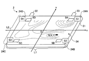
- FIG. 2 is a schematic diagram illustrating a method for estimating the local deterioration position G of the lithium ion battery 2.
- the deterioration determination system 1 determines deterioration of a lithium ion battery 2 as an example of a secondary battery. As shown in FIG. 1, the deterioration determination system 1 includes a charging device 3, a control device 4, and strain gauges 5A to 5D (pressure detecting units).
- the lithium ion battery 2 has, for example, the configuration shown in FIG. 1 and is covered with a thin, substantially rectangular parallelepiped casing 21 having a pair of main surfaces 24.
- a pair of main surfaces 24 of the housing 21 are arranged so as to face each other along the depth direction of the drawing.
- the main surface is substantially rectangular, and a positive terminal 22 and a negative terminal 23 are provided on one (upper surface in FIG. 1) of four side surfaces of the housing 21 orthogonal to the main surface 24.
- One end of each of the positive terminal 22 and the negative terminal 23 protrudes outside from the housing 21 and is connected to the charging device 3.
- the lithium ion battery 2 may be the single cell shown in FIG. 1 or an assembled battery connecting a plurality of the single cells shown in FIG.
- the charging device 3 is connected to the positive terminal 22 and the negative terminal 23 of the lithium ion battery 2 and charges the lithium ion battery 2 via the positive terminal 22 and the negative terminal 23.
- the charging device 3 has, for example, a set value of an allowable charging upper limit (safety factor) according to the degree of deterioration of the battery, and can charge up to the upper limit by checking the remaining amount of the battery. Further, the charging device 3 outputs data such as a time required for full charging to the control device 4.
- the control device 4 controls charging of the charging device 3. Further, control device 4 estimates a local deterioration position G (see FIG. 2) of lithium ion battery 2 based on information input from strain gauges 5A to 5D.
- the control device 4 has a charge control unit 41 and a deterioration determination unit 42 as functions related thereto.
- the charging control unit 41 controls a charging process of the lithium ion battery 2 by the charging device 3.
- the charging control unit 41 controls a charging time and a voltage value.
- the charging control unit 41 appropriately adjusts parameters related to charging of the lithium ion battery 2 based on the information on the deterioration position G estimated by the deterioration determination unit 42 so that the battery operates more stably.
- the data may be output to the device 3.
- the deterioration determination unit 42 estimates a local deterioration position G of the lithium ion battery 2 based on the measured values S1 to S4 of the strain gauges 5A to 5D.
- the local deterioration position G is a local portion on the main surface 24 of the lithium ion battery 2 where deterioration has progressed the most.
- the deterioration determination unit 42 estimates an expansion maximum position G where the volume expansion is maximum in a region defined by the strain gauges 5A to 5D on the main surface 24 of the lithium ion battery 2, and this expansion maximum position G Is output as the local deterioration position G.
- a specific method of estimating the deteriorated position G will be described later.
- the control device 4 may be realized by any hardware, software, or a combination thereof.
- the control device 4 mainly includes a microcomputer mainly including a CPU (Central Processing Unit), a RAM (Random Access Memory), a ROM (Read Only Memory), an auxiliary storage device, an I / O (Input-Output Interface), and the like.
- the various functions described above are realized by executing various programs stored in a ROM, an auxiliary storage device, or the like on the CPU.
- the strain gauges 5A to 5D are installed on the surface of the lithium ion battery 2 and output electric signals S1 to S4 according to the strain of the installation portion as shown in FIG.
- any type such as a metal strain gauge and a semiconductor strain gauge may be used.
- the strain gauges 5A to 5D are located at four corner regions 24A to 24D (hereinafter also referred to as “corners 24A to 24D”) of the main surface 24 (front surface) of the rectangular parallelepiped lithium ion battery 2. Each is set up.
- the strain gauge 5A is installed at a corner 24A closer to the negative electrode terminal 23 than the center of the main surface 24 and closer to the negative electrode terminal 23.
- a strain gauge 5B is installed at a corner 24B closer to the negative electrode terminal 23 than the center of the main surface 24 and farther from the negative electrode terminal 23.
- a strain gauge 5C is installed at a corner 24C closer to the positive electrode terminal 22 than the center of the main surface 24 and farther from the positive electrode terminal 22.
- a strain gauge 5D is installed at a corner 24D closer to the positive electrode terminal 22 than the center of the main surface 24 and closer to the positive electrode terminal 22.
- the strains S1 to S4 detected by the strain gauges 5A to 5D are generated according to the force (load) applied to the installation portion. It is a small mechanical change.
- the volume of the lithium ion battery 2 expands, a load is applied to the housing 21 of the lithium ion battery 2 from the inside to the outside, and the pressure on the surface of the housing 21 increases.
- the strains S1 to S4 detected by the strain gauges 5A to 5D also increase. Further, the degree of expansion of the volume differs in each part according to the difference in the degree of deterioration of each part of the battery.
- each of the strain gauges 5A to 5D arranged at the four corners of the main surface 24 depends on the position on the main surface 24 where the maximum expansion position G at which such volume expansion is maximum (that is, the local deterioration position) is located.
- the values S1 to S4 differ in appearance.
- the center position of the main surface 24 is the origin O
- the extending direction of one side on which the positive electrode terminal 22 and the negative electrode terminal 23 are provided is the x-axis direction
- the direction orthogonal thereto is the y-axis direction.
- the maximum expansion position G when the maximum expansion position G is at the origin O, the respective strain gauges 5A to 5D are substantially equidistant from the origin O, so that the gauges 5A to 5D are almost There is a tendency to output the same measured values S1 to S4. After the battery has significantly deteriorated, the maximum expansion position G tends to concentrate substantially at the center of the main surface 24.
- the maximum expansion position G when the maximum expansion position G is on the x positive side of the origin O, the measured values S1 and S2 of the strain gauges 5A and 5B at the corners 24A and 24B near the maximum expansion position G are different from those of the other strain gauges.
- the maximum expansion position G is on the x negative side of the origin O, the measured values S3 and S4 of the strain gauges 5C and 5D at the corners 24C and 24D near the maximum expansion position G are different from those of the other strain gauges. It tends to be larger than the measured values S1 and S2 of 5A and 5B. These tendencies are the same in the y-axis direction.
- the maximum expansion position G of the lithium ion battery 2, that is, the local deterioration position G is estimated by using the properties of the measured values S1 to S4 of the strain gauges 5A to 5D.
- the deterioration determining unit 42 of the control device 4 calculates the X coordinate of the maximum expansion position G in the x-axis direction and the y-axis from the measured values S1 to S4 using the following equations (1) and (2).
- the Y coordinate of the direction is calculated.
- L1 is the length of the main surface 24 in the x-axis direction
- L2 is the length of the main surface 24 in the y-axis direction.
- the calculated shift amount in the x-axis direction is calculated as the X coordinate of the maximum expansion position G.
- Equation (1) is to divide the calculated difference by the sum of the measured values S1 to S4 to normalize the difference to a value close to 0, and then multiply by the length L1 of the side of the main surface 24 in the x-axis direction.
- the calculated X coordinate is formulated so as to fall within the range between the x-axis positions of the strain gauges 5A and 5B and the x-axis positions of the strain gauges 5C and 5D.
- equation (2) the sum S1 + S4 of the measured values of the two strain gauges 5A and 5D arranged on the positive side of the y-axis of the two-dimensional coordinate system and the two The difference from the sum S2 + S3 of the measured values of the strain gauges 5B and 5C is calculated, and the amount of displacement in the y-axis direction from the center position O of the main surface 24 is calculated according to the difference.
- the calculated shift amount in the y-axis direction is calculated as the Y coordinate of the maximum expansion position G.
- Equation (2) is also similar to equation (1), in which the calculated difference is divided by the sum of the measured values S1 to S4 and normalized to a value close to 0.
- the calculated Y coordinate is formulated so as to fall within the range between the y-axis positions of the strain gauges 5A and 5D and the y-axis positions of the strain gauges 5B and 5C. I have.
- the maximum expansion position G calculated from the above equations (1) and (2) is the position where the volume expansion is maximum in the area defined by the strain gauges 5A to 5D. Therefore, it is necessary to provide at least four strain gauges 5A to 5D. However, a configuration may be employed in which more than four strain gauges are provided to improve the estimation accuracy of the deteriorated position G. For example, if four new strain gauges are arranged at the respective intermediate positions (around the midpoints of the four sides of the main surface 24) of the four strain gauges 5A to 5D installed at the four corners, the same degree as when only four are used. Since the number of sensors is doubled in a large section, a more accurate deterioration position estimation can be performed.
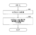
- FIG. 3 is a flowchart illustrating a procedure of a deterioration determination process of the lithium ion battery 2 performed by the deterioration determination system 1 according to the embodiment. The processing of the flowchart in FIG.
- step S01 pressure detection step
- strains S1 to S4 at four corners 24A to 24D of main surface 24 of lithium ion battery 2 are measured by strain gauges 5A to 5D.
- the measured strains S1 to S4 are output to the deterioration determination unit 42.
- step S02 deterioration determination step
- the deterioration determination unit 42 sets X, X at the maximum expansion position G on the main surface 24 where the volume expansion is maximum.
- the Y coordinate is calculated using the above equations (1) and (2).
- the deterioration determination unit 42 outputs the maximum expansion position G as a local deterioration position G where the deterioration of the battery is most advanced.
- the charge control unit 41 controls the charging related to improve the safety of the lithium ion battery 2 (for example, information on the deterioration position is stored in BMS (Battery Management). System information).
- the deterioration determination system 1 of the present embodiment is mounted on the main surface 24 of the lithium ion battery 2 and detects at least four strain gauges 5A to 5D for detecting the pressure on the battery surface at the mounting position, and the strain gauges 5A to 5D.
- a deterioration determination unit that determines deterioration of the lithium ion battery 2 based on the 5D measurement values S1 to S4.
- the deterioration determination unit 42 estimates an expansion maximum position G where the volume expansion is maximum in a region defined by the strain gauges 5A to 5D on the surface of the lithium ion battery 2.
- the expansion maximum position G on the main surface 24 of the lithium ion battery 2 that is, the deteriorated position G where the battery is most deteriorated is locally determined. Can be identified. If the deterioration position G of the lithium ion battery 2 can be specified locally, it can be used as big data used for analyzing the deterioration occurrence mechanism of the lithium ion battery 2, for example. In addition, since information such as the charge suppression control according to the deterioration state of the lithium ion battery 2 can be performed more accurately using the information on the specified deterioration position G, the safety of the lithium ion battery 2 can be improved. This can lead to a longer life of the lithium ion battery 2.
- the strain is not directly measured at each position on the main surface 24 of the battery to specify the position of the maximum strain, but the four strain gauges 5A to 5D installed at the four corners of the main surface 24 are used. Then, the coordinates of the local deterioration position G are calculated based on the measured values S1 to S4. Thus, if at least four strain gauges 5A to 5D are installed, the deterioration position can be specified, and the number of required sensors can be reduced.
- the coordinates G (x, y) of the maximum expansion position are calculated using the above equations (1) and (2), so that the measured values of the strain gauges 5A to 5D are obtained. Based on the information of S1 to S4, the local deterioration position G of the lithium ion battery 2 can be estimated with higher accuracy.
- the local deterioration position G on the battery surface is estimated based on the measured values S1 to S4 of the strain gauges 5A to 5D installed on the surface of the lithium ion battery 2.
- the cost can be reduced by using the relatively inexpensive strain gauges 5A to 5D.
- the strain gauges 5A to 5D are installed in the four corner regions 24A to 24D of the substantially rectangular main surface 24 of the lithium ion battery 2, respectively. This makes it possible to maximize the section in which the local deterioration position G can be estimated.
- the configuration in which the local degradation position G of the battery is estimated based on the measured values S1 to S4 of the strain gauges 5A to 5D installed on the battery surface is exemplified.
- Any other pressure detecting unit such as a pressure sensor other than the strain gauge may be used as long as it can measure.
- strain gauges 5A to 5D are provided in the four corner regions of the main surface 24 of the lithium ion battery 2 .
- at least four strain gauges are sufficient, and each of the strain gauges 5A to 5D May be located other than the four corners of the main surface 24.
- strain gauges 5A to 5D may be arranged on one surface (side surface, upper surface, etc.) of main surface of lithium ion battery 2 other than main surface 24.
- the lithium-ion battery 2 is exemplified as the object of the deterioration determination, but the invention can be applied to other secondary batteries such as a nickel-metal hydride battery and a lead battery.
- Deterioration determination system Lithium ion battery (secondary battery) 3 Charging device 4 Control device 5A-5D Strain gauge (pressure detector) 21 Housing 22 Positive electrode terminal 23 Negative electrode terminal 24 Main surface 24A to 24D Corner 41 Charge control unit 42 Deterioration determination unit Step S01 Pressure detection step Step S02 Deterioration determination step S1 to S4 Measured value G Expansion maximum position L1 Side in x-axis direction Length L2 Length of side in y-axis direction
Abstract
A degradation determination system that comprises: at least four strain gauges that are attached to a principal surface of a lithium ion battery and detect the pressure at the surface of the battery at the attachment locations thereof; and a degradation determination unit that determines the degradation of the lithium ion battery on the basis of measured values from the strain gauges. The degradation determination unit estimates a greatest expansion location within a region of the surface of the lithium ion battery that is demarcated by the strain gauges, the greatest expansion location being where volume expansion is greatest.
Description
本開示は、二次電池の劣化判定システム及び劣化判定方法に関する。
The present disclosure relates to a deterioration determination system and a deterioration determination method for a secondary battery.
リチウムイオン電池などの二次電池は、エネルギー密度が高く、コンパクトで軽量であるため、電気自動車やスマートフォンといった蓄電システムへ多く活用されている。
Secondary batteries such as lithium-ion batteries have a high energy density, are compact and lightweight, and are widely used in power storage systems such as electric vehicles and smartphones.
リチウムイオン電池は充放電を繰り返すことで劣化を生じる。そこで、従来より、電池の主面の圧力を測定することにより劣化時の体積膨張を検出して、リチウムイオン電池の劣化判定を行う手法が提案されている(例えば特許文献1)。
Lithium-ion batteries deteriorate due to repeated charging and discharging. Therefore, conventionally, there has been proposed a method of detecting the volume expansion at the time of deterioration by measuring the pressure of the main surface of the battery to determine the deterioration of the lithium ion battery (for example, Patent Document 1).
ところで、特許文献1などに記載される従来の劣化判別手法では、リチウムイオン電池の主面全体の圧力変化を監視しており、電池の劣化発生の有無のみを判定していた。これに対して、電池の安全性の向上などの目的のため、主面の中で体積膨張が最大となる位置を特定して、電池の劣化位置を局所的に特定したいというニーズがある。
By the way, in the conventional deterioration determination method described in Patent Literature 1 or the like, the pressure change of the entire main surface of the lithium ion battery is monitored, and only the presence or absence of deterioration of the battery is determined. On the other hand, for the purpose of improving the safety of the battery, there is a need to specify a position where the volume expansion is maximum on the main surface and to locally specify a deterioration position of the battery.
本開示は、電池の劣化位置を局所的に特定できる二次電池の劣化判定システム及び劣化判定方法を提供することを目的とする。
The present disclosure aims to provide a deterioration determination system and a deterioration determination method for a secondary battery that can locally specify a deterioration position of the battery.
本開示の実施形態の一観点に係る二次電池の劣化判定システムは、二次電池の表面に取り付けられ、取付位置の電池表面の圧力を検出する少なくとも4つの圧力検出部と、前記少なくとも4つの圧力検出部の測定値に基づいて、前記二次電池の劣化を判定する劣化判定部と、を備え、前記劣化判定部は、前記二次電池の表面のうち、前記少なくとも4つの圧力検出部により区画される領域の中で、体積膨張が最大となる体積膨張位置を推定する。
A deterioration determination system for a secondary battery according to one aspect of an embodiment of the present disclosure is mounted on a surface of a secondary battery, and detects at least four pressure detection units that detect pressure on a battery surface at an installation position; A deterioration determination unit that determines the deterioration of the secondary battery based on the measurement value of the pressure detection unit, wherein the deterioration determination unit is configured to perform the deterioration determination by the at least four pressure detection units on the surface of the secondary battery. Estimate the volume expansion position where the volume expansion becomes maximum in the partitioned area.
同様に、本開示の実施形態の一観点に係る二次電池の劣化判定方法は、二次電池の表面に取り付けられた少なくとも4つの圧力検出部により、取付位置の電池表面の圧力を検出する圧力検出ステップと、前記少なくとも4つの圧力検出部の測定値に基づいて、前記二次電池の劣化を判定する劣化判定ステップと、を含み、前記劣化判定ステップでは、前記二次電池の表面のうち、前記少なくとも4つの圧力検出部により区画される領域の中で、体積膨張が最大となる体積膨張位置が推定される。
Similarly, the method for determining deterioration of a secondary battery according to one aspect of the embodiment of the present disclosure includes a method of detecting pressure of a battery surface at an attachment position by at least four pressure detection units attached to the surface of the secondary battery. A detecting step, and a deterioration determining step of determining deterioration of the secondary battery based on the measured values of the at least four pressure detecting units, wherein the deterioration determining step includes, among the surfaces of the secondary battery, A volume expansion position at which the volume expansion is maximum is estimated in an area defined by the at least four pressure detection units.
本開示によれば、電池の劣化位置を局所的に特定できる二次電池の劣化判定システム及び劣化判定方法を提供することができる。
According to the present disclosure, it is possible to provide a deterioration determination system and a deterioration determination method for a secondary battery that can locally specify a deterioration position of the battery.
以下、添付図面を参照しながら実施形態について説明する。説明の理解を容易にするため、各図面において同一の構成要素に対しては可能な限り同一の符号を付して、重複する説明は省略する。
Hereinafter, embodiments will be described with reference to the accompanying drawings. To facilitate understanding of the description, the same components are denoted by the same reference numerals as much as possible in each drawing, and redundant description will be omitted.
図1は、実施形態に係る劣化判定システム1の概略構成を示すブロック図である。図2は、リチウムイオン電池2の局所的な劣化位置Gの推定手法を説明する模式図である。劣化判定システム1は、二次電池の一例としてのリチウムイオン電池2の劣化を判定する。図1に示すように、劣化判定システム1は、充電装置3と、制御装置4と、ひずみゲージ5A~5D(圧力検出部)とを備える。
FIG. 1 is a block diagram showing a schematic configuration of the deterioration determination system 1 according to the embodiment. FIG. 2 is a schematic diagram illustrating a method for estimating the local deterioration position G of the lithium ion battery 2. The deterioration determination system 1 determines deterioration of a lithium ion battery 2 as an example of a secondary battery. As shown in FIG. 1, the deterioration determination system 1 includes a charging device 3, a control device 4, and strain gauges 5A to 5D (pressure detecting units).
リチウムイオン電池2は、例えば図1に示す構成をとり、一対の主面24を有する薄型の略直方体形状の筐体21で被覆されている。図1では、図の奥行き方向に沿って対向するよう筐体21の一対の主面24が配置される。主面は略矩形状であり、主面24と直交する筐体21の4つの側面のうちの1つ(図1では上方の面)には正極端子22及び負極端子23が設けられる。正極端子22及び負極端子23のそれぞれの一端は筐体21から外部に突出しており、充電装置3に接続されている。リチウムイオン電池2は、図1に示す単セルでもよいし、図1に示す単セルを複数個接続する組電池でもよい。
(1) The lithium ion battery 2 has, for example, the configuration shown in FIG. 1 and is covered with a thin, substantially rectangular parallelepiped casing 21 having a pair of main surfaces 24. In FIG. 1, a pair of main surfaces 24 of the housing 21 are arranged so as to face each other along the depth direction of the drawing. The main surface is substantially rectangular, and a positive terminal 22 and a negative terminal 23 are provided on one (upper surface in FIG. 1) of four side surfaces of the housing 21 orthogonal to the main surface 24. One end of each of the positive terminal 22 and the negative terminal 23 protrudes outside from the housing 21 and is connected to the charging device 3. The lithium ion battery 2 may be the single cell shown in FIG. 1 or an assembled battery connecting a plurality of the single cells shown in FIG.
充電装置3は、リチウムイオン電池2の正極端子22及び負極端子23と接続して、正極端子22及び負極端子23を介してリチウムイオン電池2の充電を行う。充電装置3は、例えば電池の劣化度合いに応じた充電許容上限値(安全率)の設定値をもっており、電池の残量をみて上限値まで充電することができる。また、充電装置3は、満充電までの所要時間などのデータを制御装置4に出力する。
(4) The charging device 3 is connected to the positive terminal 22 and the negative terminal 23 of the lithium ion battery 2 and charges the lithium ion battery 2 via the positive terminal 22 and the negative terminal 23. The charging device 3 has, for example, a set value of an allowable charging upper limit (safety factor) according to the degree of deterioration of the battery, and can charge up to the upper limit by checking the remaining amount of the battery. Further, the charging device 3 outputs data such as a time required for full charging to the control device 4.
制御装置4は、充電装置3の充電を制御する。また、制御装置4は、ひずみゲージ5A~5Dから入力される情報に基づいて、リチウムイオン電池2の局所的な劣化位置G(図2参照)を推定する。制御装置4は、これらに関する機能として、充電制御部41と、劣化判定部42とを有する。
The control device 4 controls charging of the charging device 3. Further, control device 4 estimates a local deterioration position G (see FIG. 2) of lithium ion battery 2 based on information input from strain gauges 5A to 5D. The control device 4 has a charge control unit 41 and a deterioration determination unit 42 as functions related thereto.
充電制御部41は、充電装置3によるリチウムイオン電池2の充電処理を制御する。充電制御部41は、充電時間や電圧値の制御を行う。また、充電制御部41は、劣化判定部42により推定された劣化位置Gの情報に基づいて、電池がより安定的な動作となるようにリチウムイオン電池2の充電に関するパラメータを適宜調整して充電装置3に出力してもよい。
(4) The charging control unit 41 controls a charging process of the lithium ion battery 2 by the charging device 3. The charging control unit 41 controls a charging time and a voltage value. In addition, the charging control unit 41 appropriately adjusts parameters related to charging of the lithium ion battery 2 based on the information on the deterioration position G estimated by the deterioration determination unit 42 so that the battery operates more stably. The data may be output to the device 3.
劣化判定部42は、ひずみゲージ5A~5Dの測定値S1~S4に基づいて、リチウムイオン電池2の局所的な劣化位置Gを推定する。局所的な劣化位置Gとは、リチウムイオン電池2の主面24上において、最も劣化が進行している局所的な部分である。劣化判定部42は、リチウムイオン電池2の主面24のうち、ひずみゲージ5A~5Dにより区画される領域の中で、体積膨張が最大となる膨張最大位置Gを推定し、この膨張最大位置Gを局所的な劣化位置Gとして出力する。劣化位置Gの具体的な推定手法については後述する。
The deterioration determination unit 42 estimates a local deterioration position G of the lithium ion battery 2 based on the measured values S1 to S4 of the strain gauges 5A to 5D. The local deterioration position G is a local portion on the main surface 24 of the lithium ion battery 2 where deterioration has progressed the most. The deterioration determination unit 42 estimates an expansion maximum position G where the volume expansion is maximum in a region defined by the strain gauges 5A to 5D on the main surface 24 of the lithium ion battery 2, and this expansion maximum position G Is output as the local deterioration position G. A specific method of estimating the deteriorated position G will be described later.
制御装置4は、任意のハードウェア、ソフトウェア、或いはそれらの組み合わせにより実現されてよい。制御装置4は、例えば、CPU(Central Processing Unit)、RAM(Random Access Memory)、ROM(Read Only Memory)、補助記憶装置、I/O(Input-Output interface)等を含むマイクロコンピュータを中心に構成されてよく、ROMや補助記憶装置等に格納される各種プログラムをCPU上で実行することにより上記の各種機能が実現される。
The control device 4 may be realized by any hardware, software, or a combination thereof. The control device 4 mainly includes a microcomputer mainly including a CPU (Central Processing Unit), a RAM (Random Access Memory), a ROM (Read Only Memory), an auxiliary storage device, an I / O (Input-Output Interface), and the like. The various functions described above are realized by executing various programs stored in a ROM, an auxiliary storage device, or the like on the CPU.
ひずみゲージ5A~5Dは、リチウムイオン電池2の表面に設置され、図2に示すように設置部分のひずみに応じた電気信号S1~S4を出力する。ひずみゲージ5A~5Dとしては、例えば金属ひずみゲージや半導体ひずみゲージなど任意の種類のものを適用してよい。
The strain gauges 5A to 5D are installed on the surface of the lithium ion battery 2 and output electric signals S1 to S4 according to the strain of the installation portion as shown in FIG. As the strain gauges 5A to 5D, any type such as a metal strain gauge and a semiconductor strain gauge may be used.
ひずみゲージ5A~5Dは、例えば図2に示すように直方体形状のリチウムイオン電池2の主面24(表面)の四隅の領域24A~24D(以下では「角部24A~24D」とも表記する)にそれぞれ設置される。本実施形態では、主面24の中央より負極端子23側、かつ、負極端子23に近い側の角部24Aにひずみゲージ5Aが設置される。主面24の中央より負極端子23側、かつ、負極端子23から遠い側の角部24Bにひずみゲージ5Bが設置される。主面24の中央より正極端子22側、かつ、正極端子22から遠い側の角部24Cにひずみゲージ5Cが設置される。主面24の中央より正極端子22側、かつ、正極端子22に近い側の角部24Dにひずみゲージ5Dが設置される。
For example, as shown in FIG. 2, the strain gauges 5A to 5D are located at four corner regions 24A to 24D (hereinafter also referred to as “corners 24A to 24D”) of the main surface 24 (front surface) of the rectangular parallelepiped lithium ion battery 2. Each is set up. In the present embodiment, the strain gauge 5A is installed at a corner 24A closer to the negative electrode terminal 23 than the center of the main surface 24 and closer to the negative electrode terminal 23. A strain gauge 5B is installed at a corner 24B closer to the negative electrode terminal 23 than the center of the main surface 24 and farther from the negative electrode terminal 23. A strain gauge 5C is installed at a corner 24C closer to the positive electrode terminal 22 than the center of the main surface 24 and farther from the positive electrode terminal 22. A strain gauge 5D is installed at a corner 24D closer to the positive electrode terminal 22 than the center of the main surface 24 and closer to the positive electrode terminal 22.
ひずみゲージ5A~5Dにより検出されるひずみS1~S4(以下では「ひずみゲージ5A~5Dの測定値S1~S4」とも表記する)は、設置部分に加えられた力(荷重)に応じて発生する機械的な微小変化である。リチウムイオン電池2の体積が膨張したときに、リチウムイオン電池2の筐体21には内側から外側へ荷重がかかり、筐体21の表面の圧力が増加する。リチウムイオン電池2の表面圧力が増加すれば、ひずみゲージ5A~5Dにより検出されるひずみS1~S4も増加する。また、電池の各所の劣化度合いの違いに応じて体積の膨張度合いも各所で異なり、例えば図2に点線で示すような体積膨張の分布が主面24上に生じる。電池内で最も劣化が進んでいる局所的な劣化位置Gにおいて、電池の体積の膨張度合いも最大となる。このような体積膨張が最大となる膨張最大位置G(すなわち局所的な劣化位置)が主面24のどの位置にあるかによって、主面24の四隅に配置される各ひずみゲージ5A~5Dの測定値S1~S4の出方が異なるものとなる。
The strains S1 to S4 detected by the strain gauges 5A to 5D (hereinafter also referred to as “measured values S1 to S4 of the strain gauges 5A to 5D”) are generated according to the force (load) applied to the installation portion. It is a small mechanical change. When the volume of the lithium ion battery 2 expands, a load is applied to the housing 21 of the lithium ion battery 2 from the inside to the outside, and the pressure on the surface of the housing 21 increases. When the surface pressure of the lithium ion battery 2 increases, the strains S1 to S4 detected by the strain gauges 5A to 5D also increase. Further, the degree of expansion of the volume differs in each part according to the difference in the degree of deterioration of each part of the battery. For example, a distribution of volume expansion as shown by a dotted line in FIG. At a local deterioration position G where deterioration is most advanced in the battery, the degree of expansion of the battery volume is also maximum. The measurement of each of the strain gauges 5A to 5D arranged at the four corners of the main surface 24 depends on the position on the main surface 24 where the maximum expansion position G at which such volume expansion is maximum (that is, the local deterioration position) is located. The values S1 to S4 differ in appearance.
ここで、図2に示すように主面24の中心位置を原点Oとし、正極端子22及び負極端子23が設けられる一辺の延在方向をx軸方向とし、これと直交する方向をy軸方向とする二次元座標系を考える。この二次元座標系では、ひずみゲージ5Aは第1象限に配置され、ひずみゲージ5Dは第2象限に配置され、ひずみゲージ5Cは第3象限に配置され、ひずみゲージ5Bは第4象限に配置される。
Here, as shown in FIG. 2, the center position of the main surface 24 is the origin O, the extending direction of one side on which the positive electrode terminal 22 and the negative electrode terminal 23 are provided is the x-axis direction, and the direction orthogonal thereto is the y-axis direction. Consider a two-dimensional coordinate system as follows. In this two-dimensional coordinate system, the strain gauge 5A is arranged in the first quadrant, the strain gauge 5D is arranged in the second quadrant, the strain gauge 5C is arranged in the third quadrant, and the strain gauge 5B is arranged in the fourth quadrant. You.
このような二次元座標系において、例えば、膨張最大位置Gが原点Oにある場合には、各ひずみゲージ5A~5Dはこの原点Oからそれぞれ略等距離にあるので、各ゲージ5A~5Dはほぼ同じ値の測定値S1~S4を出力する傾向がある。なお、電池の劣化が大きく進行した後は、膨張最大位置Gは主面24の略中央に集中する傾向がある。一方、膨張最大位置Gが原点Oよりx正方向側にある場合には、膨張最大位置Gに近い角部24A、24Bのひずみゲージ5A,5Bの測定値S1、S2のほうが、他のひずみゲージ5C、5Dの測定値S3、S4より大きくなる傾向がある。また、膨張最大位置Gが原点Oよりx負方向側にある場合には、膨張最大位置Gに近い角部24C、24Dのひずみゲージ5C,5Dの測定値S3、S4のほうが、他のひずみゲージ5A、5Bの測定値S1、S2より大きくなる傾向がある。これらの傾向はy軸方向でも同様である。そこで本実施形態では、このようなひずみゲージ5A~5Dの測定値S1~S4の性質を利用して、リチウムイオン電池2の膨張最大位置G、すなわち局所的な劣化位置Gを推定している。
In such a two-dimensional coordinate system, for example, when the maximum expansion position G is at the origin O, the respective strain gauges 5A to 5D are substantially equidistant from the origin O, so that the gauges 5A to 5D are almost There is a tendency to output the same measured values S1 to S4. After the battery has significantly deteriorated, the maximum expansion position G tends to concentrate substantially at the center of the main surface 24. On the other hand, when the maximum expansion position G is on the x positive side of the origin O, the measured values S1 and S2 of the strain gauges 5A and 5B at the corners 24A and 24B near the maximum expansion position G are different from those of the other strain gauges. It tends to be larger than the measured values S3 and S4 of 5C and 5D. When the maximum expansion position G is on the x negative side of the origin O, the measured values S3 and S4 of the strain gauges 5C and 5D at the corners 24C and 24D near the maximum expansion position G are different from those of the other strain gauges. It tends to be larger than the measured values S1 and S2 of 5A and 5B. These tendencies are the same in the y-axis direction. Thus, in the present embodiment, the maximum expansion position G of the lithium ion battery 2, that is, the local deterioration position G is estimated by using the properties of the measured values S1 to S4 of the strain gauges 5A to 5D.
より詳細には、制御装置4の劣化判定部42は、以下の(1)式、(2)式を用いて測定値S1~S4から膨張最大位置Gのx軸方向のX座標と、y軸方向のY座標とを算出する。
More specifically, the deterioration determining unit 42 of the control device 4 calculates the X coordinate of the maximum expansion position G in the x-axis direction and the y-axis from the measured values S1 to S4 using the following equations (1) and (2). The Y coordinate of the direction is calculated.


ここで、L1は、主面24のx軸方向の辺の長さであり、L2は、主面24のy軸方向の辺の長さである。
Here, L1 is the length of the main surface 24 in the x-axis direction, and L2 is the length of the main surface 24 in the y-axis direction.
上記(1)式では、二次元座標系のx軸の正側に配置される2つのひずみゲージ5A、5Bの測定値の和S1+S2と、x軸の負側に配置される2つのひずみゲージ5C、5Dの測定値の和S3+S4との差分を計算し、この差分に応じて主面24の中央位置Oからのx軸方向のズレ量を算出する。この算出したx軸方向のズレ量を、膨張最大位置GのX座標として算出する。
In the above equation (1), the sum S1 + S2 of the measured values of the two strain gauges 5A and 5B arranged on the positive side of the x-axis of the two-dimensional coordinate system and the two strain gauges 5C arranged on the negative side of the x-axis , And a difference from the sum S3 + S4 of the measured values of 5D, and a shift amount in the x-axis direction from the center position O of the main surface 24 is calculated according to the difference. The calculated shift amount in the x-axis direction is calculated as the X coordinate of the maximum expansion position G.
また、(1)式は、算出した差分を測定値S1~S4の総和で除算して0近傍の数値に正規化した後に、主面24のx軸方向の辺の長さL1を乗算することで、算出されるX座標が、ひずみゲージ5A、5Bのx軸位置と、ひずみゲージ5C、5Dのx軸位置との間の範囲内に収まるように定式化されている。
Equation (1) is to divide the calculated difference by the sum of the measured values S1 to S4 to normalize the difference to a value close to 0, and then multiply by the length L1 of the side of the main surface 24 in the x-axis direction. Thus, the calculated X coordinate is formulated so as to fall within the range between the x-axis positions of the strain gauges 5A and 5B and the x-axis positions of the strain gauges 5C and 5D.
同様に、上記(2)式では、二次元座標系のy軸の正側に配置される2つのひずみゲージ5A、5Dの測定値の和S1+S4と、y軸の負側に配置される2つのひずみゲージ5B、5Cの測定値の和S2+S3との差分を計算し、この差分に応じて主面24の中央位置Oからのy軸方向のズレ量を算出する。この算出したy軸方向のズレ量を、膨張最大位置GのY座標として算出する。
Similarly, in equation (2), the sum S1 + S4 of the measured values of the two strain gauges 5A and 5D arranged on the positive side of the y-axis of the two-dimensional coordinate system and the two The difference from the sum S2 + S3 of the measured values of the strain gauges 5B and 5C is calculated, and the amount of displacement in the y-axis direction from the center position O of the main surface 24 is calculated according to the difference. The calculated shift amount in the y-axis direction is calculated as the Y coordinate of the maximum expansion position G.
また、(2)式も(1)式と同様に、算出した差分を測定値S1~S4の総和で除算して0近傍の数値に正規化した後に、主面24のy軸方向の辺の長さL2を乗算することで、算出されるY座標が、ひずみゲージ5A、5Dのy軸位置と、ひずみゲージ5B、5Cのy軸位置との間の範囲内に収まるように定式化されている。
Equation (2) is also similar to equation (1), in which the calculated difference is divided by the sum of the measured values S1 to S4 and normalized to a value close to 0. By multiplying the length L2, the calculated Y coordinate is formulated so as to fall within the range between the y-axis positions of the strain gauges 5A and 5D and the y-axis positions of the strain gauges 5B and 5C. I have.
上記(1)、(2)式より算出される膨張最大位置Gは、ひずみゲージ5A~5Dにより区画される領域の中で体積膨張が最大となる位置である。したがって、ひずみゲージ5A~5Dは少なくとも4つ設置する必要があるが、4つより多くのひずみゲージを設置して、劣化位置Gの推定精度を向上させる構成としてもよい。例えば、四隅に設置する4つのひずみゲージ5A~5Dのそれぞれの中間位置(主面24の四辺の中点あたり)に新たな4つのひずみゲージを配置すれば、4つのみの場合と同程度の大きさの区画において、センサ数を倍増するため、より高精度な劣化位置推定ができる。
膨 張 The maximum expansion position G calculated from the above equations (1) and (2) is the position where the volume expansion is maximum in the area defined by the strain gauges 5A to 5D. Therefore, it is necessary to provide at least four strain gauges 5A to 5D. However, a configuration may be employed in which more than four strain gauges are provided to improve the estimation accuracy of the deteriorated position G. For example, if four new strain gauges are arranged at the respective intermediate positions (around the midpoints of the four sides of the main surface 24) of the four strain gauges 5A to 5D installed at the four corners, the same degree as when only four are used. Since the number of sensors is doubled in a large section, a more accurate deterioration position estimation can be performed.
図3を参照して、実施形態に係る劣化判定システム1の劣化判定方法を説明する。図3は、実施形態に係る劣化判定システム1により実施されるリチウムイオン電池2の劣化判定処理の手順を示すフローチャートである。図3のフローチャートの処理は制御装置4により実施される。
With reference to FIG. 3, a description will be given of a deterioration determination method of the deterioration determination system 1 according to the embodiment. FIG. 3 is a flowchart illustrating a procedure of a deterioration determination process of the lithium ion battery 2 performed by the deterioration determination system 1 according to the embodiment. The processing of the flowchart in FIG.
ステップS01(圧力検出ステップ)では、ひずみゲージ5A~5Dにより、リチウムイオン電池2の主面24の四隅24A~24DにおけるひずみS1~S4が計測される。計測されたひずみS1~S4は劣化判定部42に出力される。
In step S01 (pressure detection step), strains S1 to S4 at four corners 24A to 24D of main surface 24 of lithium ion battery 2 are measured by strain gauges 5A to 5D. The measured strains S1 to S4 are output to the deterioration determination unit 42.
ステップS02(劣化判定ステップ)では、劣化判定部42により、ステップS01にて測定されたひずみ測定値S1~S4に基づいて、主面24上において体積膨張が最大となる膨張最大位置GのX,Y座標が、上記(1)式、(2)式を用いて算出される。劣化判定部42は、この膨張最大位置Gを電池の劣化が最も進行している局所的な劣化位置Gとして出力する。ステップS02の処理が完了すると本制御フローは終了する。
In step S02 (deterioration determination step), based on the strain measurement values S1 to S4 measured in step S01, the deterioration determination unit 42 sets X, X at the maximum expansion position G on the main surface 24 where the volume expansion is maximum. The Y coordinate is calculated using the above equations (1) and (2). The deterioration determination unit 42 outputs the maximum expansion position G as a local deterioration position G where the deterioration of the battery is most advanced. When the process in step S02 is completed, the control flow ends.
なお、ステップS02にて局所的な劣化位置Gが算出された後に、充電制御部41によりリチウムイオン電池2の安全性を向上し得るような充電に関する制御(たとえば劣化位置の情報をBMS(Battery Management System)の制御情報として活用するなど)を実施してもよい。
After the local deterioration position G is calculated in step S02, the charge control unit 41 controls the charging related to improve the safety of the lithium ion battery 2 (for example, information on the deterioration position is stored in BMS (Battery Management). System information).
このように、本実施形態の劣化判定システム1は、リチウムイオン電池2の主面24に取り付けられ、取付位置の電池表面の圧力を検出する少なくとも4つのひずみゲージ5A~5Dと、ひずみゲージ5A~5Dの測定値S1~S4に基づいて、リチウムイオン電池2の劣化を判定する劣化判定部42と、を備える。劣化判定部42は、リチウムイオン電池2の表面のうち、ひずみゲージ5A~5Dにより区画される領域の中で、体積膨張が最大となる膨張最大位置Gを推定する。
As described above, the deterioration determination system 1 of the present embodiment is mounted on the main surface 24 of the lithium ion battery 2 and detects at least four strain gauges 5A to 5D for detecting the pressure on the battery surface at the mounting position, and the strain gauges 5A to 5D. A deterioration determination unit that determines deterioration of the lithium ion battery 2 based on the 5D measurement values S1 to S4. The deterioration determination unit 42 estimates an expansion maximum position G where the volume expansion is maximum in a region defined by the strain gauges 5A to 5D on the surface of the lithium ion battery 2.
この構成により、ひずみゲージ5A~5Dの測定値S1~S4に基づいて、リチウムイオン電池2の主面24における膨張最大位置G、すなわち電池の劣化が最も進行している劣化位置Gを局所的に特定することができる。リチウムイオン電池2の劣化位置Gを局所的に特定できると、例えばリチウムイオン電池2の劣化発生メカニズムの分析などに用いるビックデータとして活用できる。また、特定した劣化位置Gの情報を利用して、リチウムイオン電池2の劣化状態に応じた充電抑制制御などの処理をより的確に行うことが可能となるので、リチウムイオン電池2の安全性を向上でき、リチウムイオン電池2の長寿命化に繋がる。
With this configuration, based on the measured values S1 to S4 of the strain gauges 5A to 5D, the expansion maximum position G on the main surface 24 of the lithium ion battery 2, that is, the deteriorated position G where the battery is most deteriorated is locally determined. Can be identified. If the deterioration position G of the lithium ion battery 2 can be specified locally, it can be used as big data used for analyzing the deterioration occurrence mechanism of the lithium ion battery 2, for example. In addition, since information such as the charge suppression control according to the deterioration state of the lithium ion battery 2 can be performed more accurately using the information on the specified deterioration position G, the safety of the lithium ion battery 2 can be improved. This can lead to a longer life of the lithium ion battery 2.
また、本実施形態では、電池の主面24上の各位置でひずみを直接計測して最大歪の位置を特定するのではなく、主面24の四隅に設置された4つのひずみゲージ5A~5Dの測定値S1~S4に基づいて、局所的な劣化位置Gの座標を算出する。これにより、少なくとも4つのひずみゲージ5A~5Dを設置すれば劣化位置を特定できるので、必要なセンサ数を少なくできる。
In the present embodiment, the strain is not directly measured at each position on the main surface 24 of the battery to specify the position of the maximum strain, but the four strain gauges 5A to 5D installed at the four corners of the main surface 24 are used. Then, the coordinates of the local deterioration position G are calculated based on the measured values S1 to S4. Thus, if at least four strain gauges 5A to 5D are installed, the deterioration position can be specified, and the number of required sensors can be reduced.
また、本実施形態の劣化判定システム1では、上記の(1)式、(2)式を用いて膨張最大位置の座標G(x、y)を算出するので、ひずみゲージ5A~5Dの測定値S1~S4の情報に基づいて、リチウムイオン電池2の局所的な劣化位置Gをより高精度に推定できる。
Further, in the deterioration determination system 1 of the present embodiment, the coordinates G (x, y) of the maximum expansion position are calculated using the above equations (1) and (2), so that the measured values of the strain gauges 5A to 5D are obtained. Based on the information of S1 to S4, the local deterioration position G of the lithium ion battery 2 can be estimated with higher accuracy.
また、本実施形態の劣化判定システム1では、リチウムイオン電池2の表面に設置されるひずみゲージ5A~5Dの測定値S1~S4に基づいて、電池表面の局所的な劣化位置Gを推定するので、比較的安価なひずみゲージ5A~5Dを用いて低コスト化を図れる。
Further, in the deterioration determination system 1 of the present embodiment, the local deterioration position G on the battery surface is estimated based on the measured values S1 to S4 of the strain gauges 5A to 5D installed on the surface of the lithium ion battery 2. The cost can be reduced by using the relatively inexpensive strain gauges 5A to 5D.
また、本実施形態の劣化判定システム1では、ひずみゲージ5A~5Dは、リチウムイオン電池2の略矩形状の主面24の四隅の領域24A~24Dにそれぞれ設置される。これにより、局所的な劣化位置Gを推定できる区画を最大化できる。
In addition, in the deterioration determination system 1 of the present embodiment, the strain gauges 5A to 5D are installed in the four corner regions 24A to 24D of the substantially rectangular main surface 24 of the lithium ion battery 2, respectively. This makes it possible to maximize the section in which the local deterioration position G can be estimated.
以上、具体例を参照しつつ本実施形態について説明した。しかし、本開示はこれらの具体例に限定されるものではない。これら具体例に、当業者が適宜設計変更を加えたものも、本開示の特徴を備えている限り、本開示の範囲に包含される。前述した各具体例が備える各要素およびその配置、条件、形状などは、例示したものに限定されるわけではなく適宜変更することができる。前述した各具体例が備える各要素は、技術的な矛盾が生じない限り、適宜組み合わせを変えることができる。
The embodiment has been described above with reference to specific examples. However, the present disclosure is not limited to these specific examples. Those in which those skilled in the art appropriately change the design of these specific examples are also included in the scope of the present disclosure as long as they have the features of the present disclosure. The components included in the specific examples described above and the arrangement, conditions, shapes, and the like of the components are not limited to those illustrated, and can be appropriately changed. The elements included in each of the specific examples described above can be appropriately changed in combination as long as no technical inconsistency occurs.
上記実施形態では、電池表面に設置されたひずみゲージ5A~5Dの測定値S1~S4に基づいて、電池の局所的な劣化位置Gを推定する構成を例示したが、電池の表面圧力の変動を計測できればよく、例えばひずみゲージ以外の圧力センサなど、他の圧力検出部を用いてもよい。
In the above embodiment, the configuration in which the local degradation position G of the battery is estimated based on the measured values S1 to S4 of the strain gauges 5A to 5D installed on the battery surface is exemplified. Any other pressure detecting unit such as a pressure sensor other than the strain gauge may be used as long as it can measure.
また、上記実施形態では、リチウムイオン電池2の主面24の四隅の領域にひずみゲージ5A~5Dを設置する構成を例示したが、少なくとも4つのひずみゲージがあればよく、各ひずみゲージ5A~5Dの設置位置は主面24の四隅以外でもよい。また、リチウムイオン電池2の表面のうち主面24以外の一面(側面や上面など)にひずみゲージ5A~5Dを配置してもよい。
Further, in the above-described embodiment, the configuration in which the strain gauges 5A to 5D are provided in the four corner regions of the main surface 24 of the lithium ion battery 2 has been exemplified. However, at least four strain gauges are sufficient, and each of the strain gauges 5A to 5D May be located other than the four corners of the main surface 24. Further, strain gauges 5A to 5D may be arranged on one surface (side surface, upper surface, etc.) of main surface of lithium ion battery 2 other than main surface 24.
上記実施形態では、劣化判定の対象としてリチウムイオン電池2を例示したが、ニッケル水素電池や鉛電池など他の二次電池にも適用可能である。
In the above embodiment, the lithium-ion battery 2 is exemplified as the object of the deterioration determination, but the invention can be applied to other secondary batteries such as a nickel-metal hydride battery and a lead battery.
本国際出願は2018年8月6日に出願された日本国特許出願2018-147714号に基づく優先権を主張するものであり、2018-147714号の全内容をここに本国際出願に援用する。
This international application claims priority based on Japanese Patent Application No. 2018-147714 filed on Aug. 6, 2018, and the entire contents of 2018-147714 are incorporated herein by reference.
1 劣化判定システム
2 リチウムイオン電池(二次電池)
3 充電装置
4 制御装置
5A~5D ひずみゲージ(圧力検出部)
21 筐体
22 正極端子
23 負極端子
24 主面
24A~24D 角部
41 充電制御部
42 劣化判定部
ステップS01 圧力検出ステップ
ステップS02 劣化判定ステップ
S1~S4 測定値
G 膨張最大位置
L1 x軸方向の辺の長さ
L2 y軸方向の辺の長さ 1Deterioration determination system 2 Lithium ion battery (secondary battery)
3 Charging device 4Control device 5A-5D Strain gauge (pressure detector)
21Housing 22 Positive electrode terminal 23 Negative electrode terminal 24 Main surface 24A to 24D Corner 41 Charge control unit 42 Deterioration determination unit Step S01 Pressure detection step Step S02 Deterioration determination step S1 to S4 Measured value G Expansion maximum position L1 Side in x-axis direction Length L2 Length of side in y-axis direction
2 リチウムイオン電池(二次電池)
3 充電装置
4 制御装置
5A~5D ひずみゲージ(圧力検出部)
21 筐体
22 正極端子
23 負極端子
24 主面
24A~24D 角部
41 充電制御部
42 劣化判定部
ステップS01 圧力検出ステップ
ステップS02 劣化判定ステップ
S1~S4 測定値
G 膨張最大位置
L1 x軸方向の辺の長さ
L2 y軸方向の辺の長さ 1
3 Charging device 4
21
Claims (6)
- 二次電池の表面に取り付けられ、取付位置の電池表面の圧力を検出する少なくとも4つの圧力検出部と、
前記少なくとも4つの圧力検出部の測定値に基づいて、前記二次電池の劣化を判定する劣化判定部と、
を備え、
前記劣化判定部は、前記二次電池の表面のうち、前記少なくとも4つの圧力検出部により区画される領域の中で、体積膨張が最大となる膨張最大位置を推定する、
二次電池の劣化判定システム。 At least four pressure detectors attached to the surface of the secondary battery and detecting pressure on the battery surface at the attachment position;
A deterioration determination unit that determines deterioration of the secondary battery based on the measurement values of the at least four pressure detection units;
With
The deterioration determination unit estimates an expansion maximum position at which volume expansion is maximum in a region defined by the at least four pressure detection units on the surface of the secondary battery.
Deterioration determination system for secondary batteries. - 前記二次電池の前記表面のうちの一面に4つの前記圧力検出部が配置され、
前記劣化判定部は、
前記一面の中央位置を原点とし、前記4つの圧力検出部のそれぞれが各象限に配置されるように二次元座標系を設定し、
前記圧力検出部のうち、前記二次元座標系のx軸の正側に配置される2つの前記圧力検出部の測定値の和と、前記二次元座標系のx軸の負側に配置される2つの前記圧力検出部の測定値の和との差分を計算し、該差分に応じて前記中央位置からのx軸方向のズレ量を算出し、
前記圧力検出部のうち、前記二次元座標系のy軸の正側に配置される2つの前記圧力検出部の測定値の和と、前記二次元座標系のy軸の負側に配置される2つの前記圧力検出部の測定値の和との差分を計算し、該差分に応じて前記中央位置からのy軸方向のズレ量を算出し、
前記x軸方向のズレ量、及び、前記y軸方向のズレ量に基づいて、前記膨張最大位置の座標を算出する、
請求項1に記載の二次電池の劣化判定システム。 Four of the pressure detectors are arranged on one of the surfaces of the secondary battery,
The deterioration determination unit includes:
The two-dimensional coordinate system is set such that the center position of the one surface is the origin, and each of the four pressure detection units is arranged in each quadrant,
Among the pressure detectors, the sum of the measured values of the two pressure detectors arranged on the positive side of the x-axis of the two-dimensional coordinate system and the negative side of the x-axis of the two-dimensional coordinate system are arranged. Calculating a difference between the sum of the measured values of the two pressure detectors and calculating a shift amount in the x-axis direction from the center position according to the difference;
Among the pressure detectors, the sum of two measured values of the pressure detectors arranged on the positive side of the y-axis of the two-dimensional coordinate system and the negative side of the y-axis of the two-dimensional coordinate system are arranged. Calculating a difference between the sum of the measured values of the two pressure detection units and calculating a shift amount in the y-axis direction from the center position according to the difference;
Calculating the coordinates of the expansion maximum position based on the displacement amount in the x-axis direction and the displacement amount in the y-axis direction,
The secondary battery deterioration determination system according to claim 1. - 前記圧力検出部は、前記二次電池の表面の略矩形状の主面の四隅にそれぞれ設置される、
請求項1または2に記載の二次電池の劣化判定システム。 The pressure detection unit is installed at each of four corners of a substantially rectangular main surface of the surface of the secondary battery,
The secondary battery deterioration determination system according to claim 1. - 前記圧力検出部はひずみゲージである、
請求項1~3のいずれか1項に記載の二次電池の劣化判定システム。 The pressure detector is a strain gauge,
The system for determining deterioration of a secondary battery according to any one of claims 1 to 3. - 前記二次電池はリチウムイオン電池である、
請求項1~4のいずれか1項に記載の二次電池の劣化判定システム。 The secondary battery is a lithium ion battery,
The system for determining deterioration of a secondary battery according to any one of claims 1 to 4. - 二次電池の表面に取り付けられた少なくとも4つの圧力検出部により、取付位置の電池表面の圧力を検出する圧力検出ステップと、
前記少なくとも4つの圧力検出部の測定値に基づいて、前記二次電池の劣化を判定する劣化判定ステップと、を含み、
前記劣化判定ステップでは、前記二次電池の表面のうち、前記少なくとも4つの圧力検出部により区画される領域の中で、体積膨張が最大となる膨張最大位置が推定される、
二次電池の劣化判定方法。 A pressure detection step of detecting pressure of the battery surface at the mounting position by at least four pressure detection units mounted on the surface of the secondary battery;
A deterioration determination step of determining deterioration of the secondary battery based on the measurement values of the at least four pressure detection units,
In the deterioration determination step, an expansion maximum position where the volume expansion is maximum is estimated in a region defined by the at least four pressure detection units on the surface of the secondary battery.
A method for determining deterioration of a secondary battery.
Priority Applications (4)
| Application Number | Priority Date | Filing Date | Title |
|---|---|---|---|
| EP19847016.3A EP3817127A4 (en) | 2018-08-06 | 2019-08-02 | Degradation determination system and degradation determination method for secondary battery |
| US17/260,733 US11467221B2 (en) | 2018-08-06 | 2019-08-02 | Degradation-determination system and method for determining degradation of secondary battery |
| CN201980049070.7A CN112514137A (en) | 2018-08-06 | 2019-08-02 | System and method for determining deterioration of secondary battery |
| US17/929,850 US20220413060A1 (en) | 2018-08-06 | 2022-09-06 | Degradation-determination system and method for determining degradation of secondary battery |
Applications Claiming Priority (2)
| Application Number | Priority Date | Filing Date | Title |
|---|---|---|---|
| JP2018-147714 | 2018-08-06 | ||
| JP2018147714A JP6788640B2 (en) | 2018-08-06 | 2018-08-06 | Deterioration judgment system and deterioration judgment method for secondary batteries |
Related Child Applications (2)
| Application Number | Title | Priority Date | Filing Date |
|---|---|---|---|
| US17/260,733 A-371-Of-International US11467221B2 (en) | 2018-08-06 | 2019-08-02 | Degradation-determination system and method for determining degradation of secondary battery |
| US17/929,850 Continuation US20220413060A1 (en) | 2018-08-06 | 2022-09-06 | Degradation-determination system and method for determining degradation of secondary battery |
Publications (1)
| Publication Number | Publication Date |
|---|---|
| WO2020031900A1 true WO2020031900A1 (en) | 2020-02-13 |
Family
ID=69415492
Family Applications (1)
| Application Number | Title | Priority Date | Filing Date |
|---|---|---|---|
| PCT/JP2019/030528 WO2020031900A1 (en) | 2018-08-06 | 2019-08-02 | Degradation determination system and degradation determination method for secondary battery |
Country Status (5)
| Country | Link |
|---|---|
| US (2) | US11467221B2 (en) |
| EP (1) | EP3817127A4 (en) |
| JP (2) | JP6788640B2 (en) |
| CN (1) | CN112514137A (en) |
| WO (1) | WO2020031900A1 (en) |
Families Citing this family (2)
| Publication number | Priority date | Publication date | Assignee | Title |
|---|---|---|---|---|
| KR20210150215A (en) | 2020-06-03 | 2021-12-10 | 주식회사 엘지에너지솔루션 | Apparatus and method for inspecting battery swelling |
| KR20220015551A (en) * | 2020-07-31 | 2022-02-08 | 주식회사 엘지에너지솔루션 | Cell jig including film type pressure sensor and method for measuring swelling of the battery cell using the same |
Citations (5)
| Publication number | Priority date | Publication date | Assignee | Title |
|---|---|---|---|---|
| WO2010122824A1 (en) * | 2009-04-22 | 2010-10-28 | 三菱電機株式会社 | Position inputting apparatus |
| JP2013020826A (en) * | 2011-07-12 | 2013-01-31 | Toyota Motor Corp | State detector of battery pack |
| JP2016134259A (en) * | 2015-01-19 | 2016-07-25 | 住友重機械工業株式会社 | Hybrid shovel |
| JP2018081854A (en) | 2016-11-17 | 2018-05-24 | トヨタ自動車株式会社 | System for controlling lithium ion secondary battery |
| JP2018147714A (en) | 2017-03-06 | 2018-09-20 | 日本特殊陶業株式会社 | Electrochemical reaction single cell and electrochemical reaction cell stack |
Family Cites Families (11)
| Publication number | Priority date | Publication date | Assignee | Title |
|---|---|---|---|---|
| KR100579377B1 (en) * | 2004-10-28 | 2006-05-12 | 삼성에스디아이 주식회사 | Secondary battery |
| JP5444762B2 (en) * | 2008-07-02 | 2014-03-19 | トヨタ自動車株式会社 | Pressure measuring device and thickness measuring device |
| US9054397B2 (en) * | 2009-08-11 | 2015-06-09 | Amphenol Thermometrics, Inc. | Battery cell with integrated sensing platform |
| JP5843222B2 (en) * | 2011-11-11 | 2016-01-13 | トヨタ自動車株式会社 | Battery system |
| DE102012207999A1 (en) * | 2012-05-14 | 2013-11-14 | Robert Bosch Gmbh | Sheath foil for a galvanic cell, electrochemical storage, electrochemical storage system, flexible foil for a sheath of a galvanic cell and method for determining a state quantity of an electrochemical storage |
| JP2014017141A (en) * | 2012-07-10 | 2014-01-30 | Canon Inc | Electronic device |
| US11079212B2 (en) * | 2014-10-24 | 2021-08-03 | Qnovo Inc. | Circuitry and techniques for determining swelling of a battery/cell and adaptive charging circuitry and techniques based thereon |
| KR101643723B1 (en) * | 2015-01-13 | 2016-07-28 | 주식회사 불스원 | pressure calculation method of cushion sheet |
| KR20180044374A (en) * | 2015-08-25 | 2018-05-02 | 옥시스 에너지 리미티드 | Battery Sensor |
| US20170098872A1 (en) * | 2015-09-16 | 2017-04-06 | Oxfordian, Llc | Wireless health monitoring of battery cells |
| CN106595914B (en) * | 2016-11-18 | 2024-01-02 | 常州普莱德新能源电池科技有限公司 | Method and device for determining expansion degree of battery cell by using strain gauge |
-
2018
- 2018-08-06 JP JP2018147714A patent/JP6788640B2/en active Active
-
2019
- 2019-08-02 WO PCT/JP2019/030528 patent/WO2020031900A1/en active Search and Examination
- 2019-08-02 CN CN201980049070.7A patent/CN112514137A/en active Pending
- 2019-08-02 US US17/260,733 patent/US11467221B2/en active Active
- 2019-08-02 EP EP19847016.3A patent/EP3817127A4/en active Pending
-
2020
- 2020-10-29 JP JP2020181075A patent/JP7094345B2/en active Active
-
2022
- 2022-09-06 US US17/929,850 patent/US20220413060A1/en active Pending
Patent Citations (5)
| Publication number | Priority date | Publication date | Assignee | Title |
|---|---|---|---|---|
| WO2010122824A1 (en) * | 2009-04-22 | 2010-10-28 | 三菱電機株式会社 | Position inputting apparatus |
| JP2013020826A (en) * | 2011-07-12 | 2013-01-31 | Toyota Motor Corp | State detector of battery pack |
| JP2016134259A (en) * | 2015-01-19 | 2016-07-25 | 住友重機械工業株式会社 | Hybrid shovel |
| JP2018081854A (en) | 2016-11-17 | 2018-05-24 | トヨタ自動車株式会社 | System for controlling lithium ion secondary battery |
| JP2018147714A (en) | 2017-03-06 | 2018-09-20 | 日本特殊陶業株式会社 | Electrochemical reaction single cell and electrochemical reaction cell stack |
Non-Patent Citations (1)
| Title |
|---|
| See also references of EP3817127A4 |
Also Published As
| Publication number | Publication date |
|---|---|
| CN112514137A (en) | 2021-03-16 |
| US11467221B2 (en) | 2022-10-11 |
| JP6788640B2 (en) | 2020-11-25 |
| JP2021015804A (en) | 2021-02-12 |
| US20220413060A1 (en) | 2022-12-29 |
| US20210270908A1 (en) | 2021-09-02 |
| EP3817127A1 (en) | 2021-05-05 |
| JP7094345B2 (en) | 2022-07-01 |
| EP3817127A4 (en) | 2021-07-21 |
| JP2020024809A (en) | 2020-02-13 |
Similar Documents
| Publication | Publication Date | Title |
|---|---|---|
| US20220413060A1 (en) | Degradation-determination system and method for determining degradation of secondary battery | |
| JP6634854B2 (en) | Storage element management device, storage element management method, storage element module, storage element management program, and moving object | |
| US10429444B2 (en) | State of charge detection device | |
| US10310025B2 (en) | Control device and control method for electric vehicle | |
| WO2020031899A1 (en) | Degradation determination system and degradation determination method for secondary battery | |
| JP7392305B2 (en) | SOC estimation device | |
| JP6749080B2 (en) | Power storage system, secondary battery control system, and secondary battery control method | |
| JP6624458B2 (en) | Battery control system | |
| JP5733146B2 (en) | Secondary battery measuring method and measuring system | |
| CN112946509A (en) | Lithium ion battery aging state estimation method based on electrode strain | |
| CN114035096A (en) | Electrochemical device SOH evaluation method, electronic device, and battery system | |
| CN114889488A (en) | Battery pack collision detection device and method | |
| JP6807014B2 (en) | Estimator, estimation method | |
| JP2015153696A (en) | Battery monitoring device and battery pack including battery monitoring device | |
| WO2020075503A1 (en) | Battery control device | |
| US10830823B2 (en) | Estimation device and estimation method | |
| JP2019061786A (en) | State estimation device of alkaline secondary battery | |
| CN117895120B (en) | Battery abnormality detection method, device and storage medium | |
| US20220399585A1 (en) | Battery system | |
| EP4053968B1 (en) | Apparatus and method for detecting damage to battery pack case | |
| WO2023207819A1 (en) | Battery module, battery pack and electric device | |
| KR20230041622A (en) | Assembled battery testing method | |
| CN117895120A (en) | Battery abnormality detection method, device and storage medium | |
| KR20230088014A (en) | Abnormal battery cell detection method and system | |
| CN114295993A (en) | Battery SOC determination method and device, vehicle and storage medium |
Legal Events
| Date | Code | Title | Description |
|---|---|---|---|
| 121 | Ep: the epo has been informed by wipo that ep was designated in this application |
Ref document number: 19847016 Country of ref document: EP Kind code of ref document: A1 |
|
| DPE1 | Request for preliminary examination filed after expiration of 19th month from priority date (pct application filed from 20040101) | ||
| NENP | Non-entry into the national phase |
Ref country code: DE |