WO2020031899A1 - 二次電池の劣化判定システム及び劣化判定方法 - Google Patents
二次電池の劣化判定システム及び劣化判定方法 Download PDFInfo
- Publication number
- WO2020031899A1 WO2020031899A1 PCT/JP2019/030522 JP2019030522W WO2020031899A1 WO 2020031899 A1 WO2020031899 A1 WO 2020031899A1 JP 2019030522 W JP2019030522 W JP 2019030522W WO 2020031899 A1 WO2020031899 A1 WO 2020031899A1
- Authority
- WO
- WIPO (PCT)
- Prior art keywords
- secondary battery
- capacity
- lithium ion
- deterioration
- ion battery
- Prior art date
Links
Images
Classifications
-
- H—ELECTRICITY
- H02—GENERATION; CONVERSION OR DISTRIBUTION OF ELECTRIC POWER
- H02J—CIRCUIT ARRANGEMENTS OR SYSTEMS FOR SUPPLYING OR DISTRIBUTING ELECTRIC POWER; SYSTEMS FOR STORING ELECTRIC ENERGY
- H02J7/00—Circuit arrangements for charging or depolarising batteries or for supplying loads from batteries
- H02J7/0047—Circuit arrangements for charging or depolarising batteries or for supplying loads from batteries with monitoring or indicating devices or circuits
- H02J7/005—Detection of state of health [SOH]
-
- G—PHYSICS
- G01—MEASURING; TESTING
- G01R—MEASURING ELECTRIC VARIABLES; MEASURING MAGNETIC VARIABLES
- G01R31/00—Arrangements for testing electric properties; Arrangements for locating electric faults; Arrangements for electrical testing characterised by what is being tested not provided for elsewhere
- G01R31/36—Arrangements for testing, measuring or monitoring the electrical condition of accumulators or electric batteries, e.g. capacity or state of charge [SoC]
- G01R31/392—Determining battery ageing or deterioration, e.g. state of health
-
- H—ELECTRICITY
- H01—ELECTRIC ELEMENTS
- H01M—PROCESSES OR MEANS, e.g. BATTERIES, FOR THE DIRECT CONVERSION OF CHEMICAL ENERGY INTO ELECTRICAL ENERGY
- H01M10/00—Secondary cells; Manufacture thereof
- H01M10/42—Methods or arrangements for servicing or maintenance of secondary cells or secondary half-cells
- H01M10/425—Structural combination with electronic components, e.g. electronic circuits integrated to the outside of the casing
-
- H—ELECTRICITY
- H01—ELECTRIC ELEMENTS
- H01M—PROCESSES OR MEANS, e.g. BATTERIES, FOR THE DIRECT CONVERSION OF CHEMICAL ENERGY INTO ELECTRICAL ENERGY
- H01M10/00—Secondary cells; Manufacture thereof
- H01M10/42—Methods or arrangements for servicing or maintenance of secondary cells or secondary half-cells
- H01M10/44—Methods for charging or discharging
-
- H—ELECTRICITY
- H01—ELECTRIC ELEMENTS
- H01M—PROCESSES OR MEANS, e.g. BATTERIES, FOR THE DIRECT CONVERSION OF CHEMICAL ENERGY INTO ELECTRICAL ENERGY
- H01M10/00—Secondary cells; Manufacture thereof
- H01M10/42—Methods or arrangements for servicing or maintenance of secondary cells or secondary half-cells
- H01M10/48—Accumulators combined with arrangements for measuring, testing or indicating the condition of cells, e.g. the level or density of the electrolyte
-
- H—ELECTRICITY
- H02—GENERATION; CONVERSION OR DISTRIBUTION OF ELECTRIC POWER
- H02J—CIRCUIT ARRANGEMENTS OR SYSTEMS FOR SUPPLYING OR DISTRIBUTING ELECTRIC POWER; SYSTEMS FOR STORING ELECTRIC ENERGY
- H02J7/00—Circuit arrangements for charging or depolarising batteries or for supplying loads from batteries
- H02J7/007—Regulation of charging or discharging current or voltage
- H02J7/0071—Regulation of charging or discharging current or voltage with a programmable schedule
-
- H—ELECTRICITY
- H02—GENERATION; CONVERSION OR DISTRIBUTION OF ELECTRIC POWER
- H02J—CIRCUIT ARRANGEMENTS OR SYSTEMS FOR SUPPLYING OR DISTRIBUTING ELECTRIC POWER; SYSTEMS FOR STORING ELECTRIC ENERGY
- H02J7/00—Circuit arrangements for charging or depolarising batteries or for supplying loads from batteries
- H02J7/007—Regulation of charging or discharging current or voltage
- H02J7/007188—Regulation of charging or discharging current or voltage the charge cycle being controlled or terminated in response to non-electric parameters
- H02J7/00719—Regulation of charging or discharging current or voltage the charge cycle being controlled or terminated in response to non-electric parameters in response to degree of gas development in the battery
-
- H—ELECTRICITY
- H01—ELECTRIC ELEMENTS
- H01M—PROCESSES OR MEANS, e.g. BATTERIES, FOR THE DIRECT CONVERSION OF CHEMICAL ENERGY INTO ELECTRICAL ENERGY
- H01M10/00—Secondary cells; Manufacture thereof
- H01M10/05—Accumulators with non-aqueous electrolyte
- H01M10/052—Li-accumulators
- H01M10/0525—Rocking-chair batteries, i.e. batteries with lithium insertion or intercalation in both electrodes; Lithium-ion batteries
-
- H—ELECTRICITY
- H01—ELECTRIC ELEMENTS
- H01M—PROCESSES OR MEANS, e.g. BATTERIES, FOR THE DIRECT CONVERSION OF CHEMICAL ENERGY INTO ELECTRICAL ENERGY
- H01M2200/00—Safety devices for primary or secondary batteries
- H01M2200/20—Pressure-sensitive devices
-
- H—ELECTRICITY
- H02—GENERATION; CONVERSION OR DISTRIBUTION OF ELECTRIC POWER
- H02J—CIRCUIT ARRANGEMENTS OR SYSTEMS FOR SUPPLYING OR DISTRIBUTING ELECTRIC POWER; SYSTEMS FOR STORING ELECTRIC ENERGY
- H02J7/00—Circuit arrangements for charging or depolarising batteries or for supplying loads from batteries
- H02J7/0029—Circuit arrangements for charging or depolarising batteries or for supplying loads from batteries with safety or protection devices or circuits
- H02J7/00302—Overcharge protection
-
- Y—GENERAL TAGGING OF NEW TECHNOLOGICAL DEVELOPMENTS; GENERAL TAGGING OF CROSS-SECTIONAL TECHNOLOGIES SPANNING OVER SEVERAL SECTIONS OF THE IPC; TECHNICAL SUBJECTS COVERED BY FORMER USPC CROSS-REFERENCE ART COLLECTIONS [XRACs] AND DIGESTS
- Y02—TECHNOLOGIES OR APPLICATIONS FOR MITIGATION OR ADAPTATION AGAINST CLIMATE CHANGE
- Y02E—REDUCTION OF GREENHOUSE GAS [GHG] EMISSIONS, RELATED TO ENERGY GENERATION, TRANSMISSION OR DISTRIBUTION
- Y02E60/00—Enabling technologies; Technologies with a potential or indirect contribution to GHG emissions mitigation
- Y02E60/10—Energy storage using batteries
Definitions
- the present disclosure relates to a deterioration determination system and a deterioration determination method for a secondary battery.
- Secondary batteries such as lithium-ion batteries have a high energy density, are compact and lightweight, and are widely used in power storage systems such as electric vehicles and smartphones.
- Lithium-ion batteries deteriorate due to repeated charging and discharging. Therefore, conventionally, the state of deterioration of a lithium ion battery is estimated by measuring and monitoring the voltage, current, temperature, and the like between the electrode terminals, and charge control is performed in consideration of the degree of deterioration (for example, Patent Document 1). .
- the present disclosure has an object to provide a deterioration determination system and a deterioration determination method for a secondary battery that can more accurately estimate a deterioration state inside a battery.
- a deterioration determination system for a secondary battery a volume change detection unit that detects a volume change of the secondary battery, and a capacity change detection unit that detects a capacity change of the secondary battery, A charge control unit that controls charging of the secondary battery, wherein the charge control unit detects a volume expansion of the secondary battery by the volume change detection unit, and the capacity change detection unit When the capacity reduction of the secondary battery is not detected, it is determined that the secondary battery is in a deteriorated state.
- a method for determining deterioration of a secondary battery includes a volume change detection step of detecting a volume change of the secondary battery, and a capacity change detection of detecting a capacity change of the secondary battery. And when the volume change of the secondary battery is detected in the volume change detecting step, and when the capacity reduction of the secondary battery is not detected in the capacity change detecting step. And a deterioration determining step of determining that is in a deteriorated state.
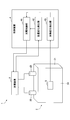
- FIG. 1 is a block diagram showing a schematic configuration of the deterioration determination system 1 according to the embodiment.
- the deterioration determination system 1 determines deterioration of a lithium ion battery 2 as an example of a secondary battery.
- the deterioration determination system 1 includes a charging device 3, a control device 4, and a strain gauge 5.
- the lithium ion battery 2 has, for example, the configuration shown in FIG. 1 and is covered with a thin, substantially rectangular parallelepiped casing 21 having a pair of main surfaces 24.
- a pair of main surfaces 24 of the housing 21 are arranged so as to face each other along the depth direction of the drawing.
- the main surface is substantially rectangular, and a positive terminal 22 and a negative terminal 23 are provided on one (upper surface in FIG. 1) of four side surfaces of the housing 21 orthogonal to the main surface 24.
- One end of each of the positive terminal 22 and the negative terminal 23 protrudes outside from the housing 21 and is connected to the charging device 3.
- the lithium ion battery 2 may be the single cell shown in FIG. 1 or an assembled battery connecting a plurality of the single cells shown in FIG.
- the charging device 3 is connected to the positive terminal 22 and the negative terminal 23 of the lithium ion battery 2 and charges the lithium ion battery 2 via the positive terminal 22 and the negative terminal 23.
- the charging device 3 has, for example, a set value of a charging allowable upper limit value according to the degree of deterioration of the battery, and can charge up to the upper limit value by checking the remaining amount of the battery. Further, the charging device 3 outputs data such as a time required for full charging to the control device 4.
- the control device 4 controls charging of the charging device 3. Further, control device 4 determines the degree of deterioration of lithium ion battery 2 based on information input from strain gauge 5.
- the control device 4 has a charge control unit 41, a capacity change detection unit 42, and a volume change detection unit 43 as functions related thereto.
- the charging control unit 41 controls a charging process of the lithium ion battery 2 by the charging device 3.
- the charging control unit 41 controls a charging time and a voltage value. Further, the charging control unit 41 changes the set value of the allowable charging upper limit value in accordance with the degree of deterioration of the lithium ion battery 2 and outputs the set value to the charging device 3. For example, the higher the deterioration, the smaller the allowable charging upper limit value is set to prevent overcharging, so that the battery operates more stably.
- the capacity change detection unit 42 detects a change in the capacity of the lithium ion battery 2 when fully charged.
- the capacity change detection unit 42 holds, for example, information on a required time (charge time) until full charge under various conditions (temperature, remaining charge, etc.) at the time of shipment as a table, and performs charging under the same condition.
- the deterioration of the battery can be determined by comparing with the charging time at the time of the operation.
- the volume change detection unit 43 detects the volume change of the lithium ion battery 2 based on the measurement value of the strain gauge 5. For example, when the measured value of the strain gauge is larger than the reference value, it can be determined that the volume of the battery is expanded.
- the control device 4 may be realized by any hardware, software, or a combination thereof.
- the control device 4 mainly includes a microcomputer mainly including a CPU (Central Processing Unit), a RAM (Random Access Memory), a ROM (Read Only Memory), an auxiliary storage device, an I / O (Input-Output Interface), and the like.
- the various functions described above are realized by executing various programs stored in a ROM, an auxiliary storage device, or the like on the CPU.
- the strain gauge 5 is installed on the surface of the lithium ion battery 2 and outputs an electric signal according to the strain of the installation portion.
- the strain gauge 5 is installed at a substantially central position of the main surface 24 of the rectangular parallelepiped lithium ion battery 2 as shown in FIG. 1, for example.
- the strain detected by the strain gauge 5 is a small mechanical change generated according to a force (load) applied to the installation portion.
- a force load
- the strain detected by the strain gauge 5 also increases. Therefore, in the present embodiment, a change in volume of the lithium ion battery 2 is detected based on the strain detected by the strain gauge 5.
- the strain gauge 5 only needs to detect the expansion of the battery surface caused by the deterioration of the lithium ion battery 2, and the installation position may be other than the main surface 24. For example, it may be installed on a side surface orthogonal to the main surface 24 of the lithium ion battery 2. Further, as the strain gauge 5, any type such as a metal strain gauge and a semiconductor strain gauge may be applied.
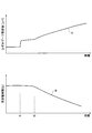
- FIG. 2 is a diagram showing a relationship between measured values of strain gauges in a charge / discharge test in which charge / discharge is repeated and charge / discharge times until full charge / full discharge.
- charge and discharge were repeatedly performed up to a predetermined charge / discharge allowable amount, and the measured values of the strain gauge and the charge / discharge time during the charge / discharge were recorded.
- Graph A in the figure shows the characteristic of the measured value of the strain gauge with the lapse of time of the charge / discharge test.
- Graph B in the figure shows the characteristics of the charge / discharge time with the lapse of time in the charge / discharge test.
- the horizontal axis in the figure indicates the elapsed time of the charge / discharge test, and the vertical axis indicates the measured value of the strain gauge ( ⁇ V) and the charge / discharge time (s), respectively.
- the charging / discharging time is maintained substantially constant until time t2, and decreases after time t2.
- Decreasing the charge / discharge time is a state in which the allowable amount of the lithium-ion battery 2 that can be charged is gradually decreasing, which means that the battery is deteriorating. That is, when the charge / discharge time is observed, the deterioration of the battery can be detected only after the time t2 has elapsed from the start of the test.
- the strain gauge measured value of the graph A increases stepwise at the time t1 earlier than the time t2, and in the section from the time t1 to t2, increases relatively gradually with respect to the transition after the time t2. . Then, after the time t2, it increases relatively relatively to the transition from the time t1 to t2.
- An increase in the measured value of the strain gauge means that the surface of the lithium ion battery 2 is expanding, the volume of the battery is expanding, and the deterioration of the battery is in progress. That is, when the measured value of the strain gauge 5 is observed, the deterioration of the battery can be detected from time t1 earlier than when the charge / discharge time is observed.
- the charge / discharge time is substantially constant while the measured value of the strain gauge has a gradual increasing tendency, so that the first sign of deterioration can be observed.
- the charge / discharge time decreases, while the measured value of the strain gauge tends to increase more than in the section from the time t1 to t2, so that the second sign of deterioration can be observed.
- the deterioration state of the lithium ion battery 2 is estimated by measuring and monitoring the voltage, current, temperature, and the like between the positive terminal 22 and the negative terminal 23. That is, it was based on the electrical behavior of the battery. This is based on the idea that electrical behavior is easier to appear than physical behavior such as volume expansion. The electrical behavior is correlated with the charge / discharge time shown in FIG.
- the deterioration determination system 1 of the present embodiment pays attention to this point as a battery deterioration determination point. That is, the deterioration determination system 1 detects a volume change based on the measured value of the strain gauge, detects a capacity change from the charge / discharge time, and determines battery deterioration in consideration of two characteristics of the volume change and the capacity change. As a result, battery deterioration can be detected even in a section between times t1 and t2, which cannot be detected only by the information on the charge / discharge time.
- times t1 and t2 shown in FIG. 2 fluctuate as appropriate in accordance with the execution conditions of the charge / discharge test, such as the outside air temperature, the battery capacity, and the type of the battery.
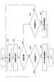
- FIG. 3 is a flowchart illustrating a procedure of a deterioration determination process of the lithium ion battery 2 performed by the deterioration determination system 1 according to the embodiment. The processing of the flowchart in FIG.
- the volume change detection unit 43 calculates the volume change (expansion amount) of the lithium ion battery 2 based on the measurement value of the strain gauge 5.
- the volume change detection unit 43 has the data of the measured value of the strain gauge 5 in the initial state, and can calculate the magnitude of the expansion amount according to the magnitude of the deviation between the current measured value and the measured value in the initial state.
- the capacity change detection unit 42 calculates the capacity change of the lithium ion battery 2.
- the capacity change detection unit 42 acquires, for example, information on the charging time from the charging device 3 to the current full charge of the lithium ion battery 2 and information on measurement conditions such as the temperature and the remaining charge amount, and holds the information as a table.
- the change in capacity is calculated by comparing the charging time under the same condition at the time of shipment. For example, the capacity change can be calculated such that the larger the deviation between the current charging time and the initial charging time, the smaller the capacity.
- step S03 (capacity change detection step) the capacity change detection unit 42 determines whether or not the capacity of the lithium ion battery 2 is reduced based on the capacity change amount of the lithium ion battery 2 calculated in step S02. You. For example, the capacitance change detection unit 42 can detect a decrease in the capacitance when the capacitance change amount has decreased by a predetermined value or more. If the result of determination in step S03 is that capacity reduction has occurred (Yes in step S03), the flow proceeds to step S06. If the capacity has not been reduced (No in step S03), the process proceeds to step S04.
- the state where it is determined in step S03 that no capacity reduction has occurred and there is no capacity change means that the capacity change amount of the lithium ion battery 2 calculated in step S02 is 0 and the current capacity value and the initial state Not only the state where the capacitance value is the same but also the state where the amount of change in the capacitance is within a predetermined range can be included.
- step S04 volume change detection step
- the volume change detection unit 43 determines whether or not the amount of expansion of the volume of the lithium ion battery 2 calculated in step S01 is equal to or greater than a threshold value V1. It is desirable that the threshold value V1 be smaller than the rising amount of the strain gauge measurement value at the time t1 shown in FIG. Thereby, volume expansion in the section from time t1 to time t2 can be detected. If the result of determination in step S04 is that the volume expansion is equal to or greater than V1 (Yes in step S04), the flow proceeds to step S05. When the volume expansion is equal to or less than V1 (No in step S04), the process returns to step S01.
- the expansion detection in step S04 may include a configuration in which the volume increase rate (slope of the graph A in FIG. 2) is viewed in addition to the configuration in which the volume change amount is viewed. Thereby, for example, a step-like change at the time t1 of the graph A can be quickly detected, and the volume expansion can be easily detected. Further, the measured value of the strain gauge 5 may be used as it is in the determination without being converted into the volume in step S01.
- step S05 deterioration determination step
- step S04 it is determined that the volume expansion is equal to or more than the predetermined amount V1, so that the charge control unit 41 It can be determined that the first deterioration has occurred in the lithium ion battery 2 at any one of the times t1 to t2 shown in FIG. Therefore, the first charge suppression control that suppresses the influence of the first deterioration state is performed.
- the allowable charge upper limit value is reduced once or plural times according to the degree of deterioration of the lithium ion battery 2.
- a value SOH: States @ of ⁇ Health
- SOH States @ of ⁇ Health
- the parameter to be adjusted by the suppression control may be a reduction in the charging time, a reduction in the charging voltage, or an increase in the lower discharge limit, in addition to the reduction in the allowable charging upper limit.
- step S06 volume change detection step
- the volume change detection unit 43 determines whether or not the amount of expansion of the volume of the lithium ion battery 2 calculated in step S01 is equal to or greater than a threshold value V2.
- the threshold value V2 is preferably an arbitrary value of the strain gauge measurement value after time t2 shown in FIG. Thereby, the volume expansion after time t2 can be detected. If the result of determination in step S06 is that the volume expansion is equal to or greater than V2 (Yes in step S06), the flow proceeds to step S07. On the other hand, when the volume expansion is equal to or less than V2 (No in step S06), the process returns to step S01 without performing the second charge suppression control yet at any timing after time t2 illustrated in FIG. .
- step S07 it is determined in step S03 that the capacity is reduced, and in step S06, it is determined that the volume expansion is equal to or more than the predetermined amount V2. It is any timing after the time t2, and it can be determined that the lithium ion battery 2 has undergone the second deterioration. Therefore, the second charge suppression control that suppresses the influence of the second deterioration state is performed.
- the charge allowable upper limit value is reduced once or plural times according to the degree of deterioration of the lithium ion battery 2.
- the SOH is estimated based on, for example, the change amount (volume expansion amount) of the strain gauge measurement value, the change amount of the battery capacity, or both, and the charging permission is made according to the estimated SOH.
- the amount by which the upper limit is reduced can be adjusted.
- the reduction amount of the allowable charging upper limit value of the second charge suppression control may be different from that of the first charge suppression control. Further, the second charge suppression control may have the same contents as the first charge suppression control.
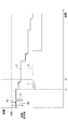
- FIG. 4 is a diagram illustrating an example of adjustment of the allowable charging upper limit value as the usage time of the lithium ion battery 2 elapses.
- a graph C in FIG. 4 shows a transition of the allowable charging upper limit in the deterioration determination system 1 according to the embodiment.
- Graph D in FIG. 4 shows the transition of the allowable charging upper limit value when only the conventional electric behavior is observed as a comparative example.
- the horizontal axis in the figure indicates the usage time, and the vertical axis indicates the capacity of the lithium ion battery 2.
- the chargeable capacity (initial capacity) of the lithium ion battery 2 in the initial state is shown as 100%.
- the deterioration of the lithium ion battery 2 cannot be detected before the time t2 because the electrical behavior does not change. For this reason, as shown in the graph D of FIG. 4, the initial value (initial safety factor) of the charge allowable upper limit is set low, and the reduction M2 (margin) from the initial capacity 100% of the lithium ion battery 2 is increased. In the section up to time t2, overcharging can be prevented with a constant initial safety factor.
- the “margin” can also be expressed as a difference between the actual chargeable capacity of the lithium ion battery 2 and the upper limit value of the capacity that allows charging in consideration of safety such as overcharge prevention (charge upper limit value). .
- a state in which the volume change of the lithium ion battery 2 is detected by the volume change detection unit 43 and a reduction in the capacity of the lithium ion battery 2 are detected by the capacity change detection unit 42.
- the state is not performed, it is determined that the lithium ion battery 2 is in a deteriorated state. That is, the deterioration determination is performed based on the physical behavior in addition to the electrical behavior of the lithium ion battery 2.
- the deterioration of the lithium ion battery 2 can be detected even in a section between times t1 and t2, which is a timing earlier than the time t2.
- battery deterioration can be detected even in a section at an earlier timing that could not be detected by the conventional deterioration determination based on electrical behavior.
- the deterioration detection timing can be brought forward, and the resolution of the deterioration determination can be increased, so that the accuracy of the deterioration determination is improved. Therefore, the deterioration determination system 1 can estimate the deterioration state inside the battery with higher accuracy.
- the control device 4 when the control device 4 determines that the lithium ion battery 2 is in a deteriorated state, the control device 4 performs charge suppression control for suppressing charging of the lithium ion battery 2. Specifically, the charge allowable upper limit value is reduced according to the degree of deterioration, and the battery capacity at full charge is suppressed.
- the accuracy of the deterioration determination of the lithium ion battery 2 can be improved, so that the first deterioration detection timing can be brought forward as compared with the conventional case. If the deterioration detection timing can be advanced, the charge suppression control can also be performed earlier than before, and the process of lowering the allowable charging upper limit value can be performed. For this reason, since the initial value (initial safety factor) of the allowable charging upper limit value does not need to consider the time after time t1, the margin provided in the battery use area can be reduced as compared with the conventional case, and the initial value of the allowable charging upper limit value can be reduced compared to the conventional case.
- the control for reducing the allowable charging upper limit can be performed more finely than the conventional control method by the highly accurate deterioration determination.
- the initial margin M1 can be made smaller than the conventional margin M2 by X, and the subsequent margin is also smaller than the conventional one over the entire time course.
- the battery can be used up to the limit of the battery use area as compared with the related art.
- the deterioration determination system 1 of the present embodiment can perform charging with a capacity closer to the original capacity (100%) of the lithium ion battery 2 as compared with the related art, so that charging efficiency can be improved.
- the charge control unit 41 detects when the volume change detection unit 43 first detects the volume expansion of the lithium ion battery 2, that is, at the time t1 shown in FIGS. At this time, it is determined that the lithium ion battery 2 is in a deteriorated state. Thereby, the deterioration of the lithium ion battery 2 can be detected at the moment when the physical behavior related to the deterioration of the lithium ion battery 2 shown in FIG. 2 first occurs, so that the accuracy of the deterioration determination can be further improved.
- the volume change detection unit 43 detects a volume change of the lithium ion battery 2 based on a change in the surface pressure of the lithium ion battery 2.
- a load is applied from the inside to the outside of the battery 2 and the surface pressure increases, so that a change in the surface pressure of the lithium ion battery 2 has a strong correlation with a change in volume. It can be said that. Therefore, by monitoring the change in the surface pressure, the change in the volume of the lithium ion battery 2 can be accurately detected.
- the pressure change on the battery surface is detected based on the change in the measured value of the strain gauge 5 installed on the surface of the lithium ion battery 2, a relatively inexpensive strain gauge 5 is used. Cost reduction can be achieved by using this.
- the capacity change detection unit 42 detects a change in capacity of the lithium ion battery 2 by comparing charging characteristics (for example, charging time) of the lithium ion battery 2 under the same conditions. I do. Since the change in the charging characteristic has a strong correlation with the change in the capacity, the change in the capacity of the lithium ion battery 2 can be detected with high accuracy by monitoring the change in the charging characteristic.
- the configuration in which the volume change detection unit 43 detects the volume expansion of the battery based on the measurement value of the strain gauge 5 installed on the battery surface is exemplified, but it is sufficient that the variation in the surface pressure of the battery can be measured.
- a pressure sensor other than a strain gauge may be used.
- information measured on a surface other than the battery surface may be used. For example, when the lithium ion battery 2 is deteriorated, gas tends to be generated inside the battery. Therefore, a method of detecting gas generation by installing a gas sensor inside the battery may be used.
- the capacity change detection unit 42 compares the current charging time with the current charging time when the conditions such as the temperature and the remaining charge amount are the same, thereby determining the capacity of the lithium ion battery 2.
- the method of detecting a change has been exemplified, the method of detecting a capacitance change is not limited to this. For example, each time charging / discharging is performed, the information on the charging / discharging time corresponding to the condition at the time of execution may be updated from that at the time of shipment, and a change in the charging / discharging time may be detected based on the updated information. Further, a configuration may be employed in which a change in capacity is detected using charging characteristics (such as chargeable capacity) other than the charging time.
- the lithium-ion battery 2 is exemplified as the object of the deterioration determination, but the invention can be applied to other secondary batteries such as a nickel-metal hydride battery and a lead battery.
- the configuration in which the charge suppression control is performed when the deterioration is determined is exemplified.
- other control or processing may be performed after the deterioration is determined.
Abstract
劣化判定システムは、リチウムイオン電池の体積変化を検出する体積変化検出部と、リチウムイオン電池の容量変化を検出する容量変化検出部と、リチウムイオン電池の充電を制御する充電制御部と、を備える。充電制御部は、体積変化検出部によりリチウムイオン電池の体積膨張が検出された状態、かつ、容量変化検出部によりリチウムイオン電池の容量低減が検出されない状態のとき、リチウムイオン電池が劣化状態であると判定する。
Description
本開示は、二次電池の劣化判定システム及び劣化判定方法に関する。
リチウムイオン電池などの二次電池は、エネルギー密度が高く、コンパクトで軽量であるため、電気自動車やスマートフォンといった蓄電システムへ多く活用されている。
リチウムイオン電池は充放電を繰り返すことで劣化を生じる。そこで従来より、電極端子間の電圧、電流、温度などを測定し監視することによって、リチウムイオン電池の劣化状態を推定し、劣化度合いを考慮した充電制御が行われている(例えば特許文献1)。
しかしながら、劣化度合いを考慮した充電制御では、過充電を回避して安全性を十分に担保できるように、二次電池の使用領域に大きなマージンが設けられる。このため、実際の充電できる二次電池の容量と、充電制御で設定される充電容量の上限値(充電許容上限値)との偏差が大きくなり、充電効率が低いという問題があった。充電効率を向上させるためには、二次電池の劣化判定の精度を改善して、二次電池の充電容量のマージンを少なくできるのが望ましい。
本開示は、より高精度に電池内部の劣化状態を推定できる二次電池の劣化判定システム及び劣化判定方法を提供することを目的とする。
本開示の実施形態の一観点に係る二次電池の劣化判定システムは、二次電池の体積変化を検出する体積変化検出部と、前記二次電池の容量変化を検出する容量変化検出部と、前記二次電池の充電を制御する充電制御部と、を備え、前記充電制御部は、前記体積変化検出部により前記二次電池の体積膨張が検出された状態、かつ、前記容量変化検出部により前記二次電池の容量低減が検出されない状態のとき、前記二次電池が劣化状態であると判定する。
同様に、本開示の実施形態の一観点に係る二次電池の劣化判定方法は、二次電池の体積変化を検出する体積変化検出ステップと、前記二次電池の容量変化を検出する容量変化検出ステップと、前記体積変化検出ステップにて前記二次電池の体積膨張が検出された状態、かつ、前記容量変化検出ステップにて前記二次電池の容量低減が検出されない状態のとき、前記二次電池が劣化状態であると判定する劣化判定ステップと、を含む。
本開示によれば、劣化判定の精度を向上できる二次電池の劣化判定システム及び劣化判定方法を提供することができる。
以下、添付図面を参照しながら実施形態について説明する。説明の理解を容易にするため、各図面において同一の構成要素に対しては可能な限り同一の符号を付して、重複する説明は省略する。
図1は、実施形態に係る劣化判定システム1の概略構成を示すブロック図である。劣化判定システム1は、二次電池の一例としてのリチウムイオン電池2の劣化を判定する。図1に示すように、劣化判定システム1は、充電装置3と、制御装置4と、ひずみゲージ5とを備える。
リチウムイオン電池2は、例えば図1に示す構成をとり、一対の主面24を有する薄型の略直方体形状の筐体21で被覆されている。図1では、図の奥行き方向に沿って対向するよう筐体21の一対の主面24が配置される。主面は略矩形状であり、主面24と直交する筐体21の4つの側面のうちの1つ(図1では上方の面)には正極端子22及び負極端子23が設けられる。正極端子22及び負極端子23のそれぞれの一端は筐体21から外部に突出しており、充電装置3に接続されている。リチウムイオン電池2は、図1に示す単セルでもよいし、図1に示す単セルを複数個接続する組電池でもよい。
充電装置3は、リチウムイオン電池2の正極端子22及び負極端子23と接続して、正極端子22及び負極端子23を介してリチウムイオン電池2の充電を行う。充電装置3は、例えば電池の劣化度合いに応じた充電許容上限値の設定値をもっており、電池の残量をみて上限値まで充電することができる。また、充電装置3は、満充電までの所要時間などのデータを制御装置4に出力する。
制御装置4は、充電装置3の充電を制御する。また、制御装置4は、ひずみゲージ5から入力される情報に基づいてリチウムイオン電池2の劣化度合いを判定する。制御装置4は、これらに関する機能として、充電制御部41と、容量変化検出部42と、体積変化検出部43とを有する。
充電制御部41は、充電装置3によるリチウムイオン電池2の充電処理を制御する。充電制御部41は、充電時間や電圧値の制御を行う。また、充電制御部41は、リチウムイオン電池2の劣化度合いに応じて充電許容上限値の設定値を変更して、充電装置3に出力する。例えば劣化が大きくなるほど充電許容上限値を小さくして、過充電を防止して、電池がより安定的な動作となるようにする。
容量変化検出部42は、リチウムイオン電池2の満充電時の容量の変化を検出する。容量変化検出部42は、例えば出荷時にさまざまな条件下(気温、充電残量など)での満充電までの所要時間(充電時間)の情報をテーブルとして保持しており、同一条件下で充電をおこなったときの充電時間と比較することで、電池の劣化を判定できる。
体積変化検出部43は、ひずみゲージ5の測定値に基づき、リチウムイオン電池2の体積変化を検出する。例えば、ひずみゲージの測定値が基準値より大きい場合には、電池の体積が膨張していると判定できる。
制御装置4は、任意のハードウェア、ソフトウェア、或いはそれらの組み合わせにより実現されてよい。制御装置4は、例えば、CPU(Central Processing Unit)、RAM(Random Access Memory)、ROM(Read Only Memory)、補助記憶装置、I/O(Input-Output interface)等を含むマイクロコンピュータを中心に構成されてよく、ROMや補助記憶装置等に格納される各種プログラムをCPU上で実行することにより上記の各種機能が実現される。
ひずみゲージ5は、リチウムイオン電池2の表面に設置され、設置部分のひずみに応じた電気信号を出力する。ひずみゲージ5は、例えば図1に示すように直方体形状のリチウムイオン電池2の主面24の略中央位置に設置される。ひずみゲージ5により検出されるひずみは、設置部分に加えられた力(荷重)に応じて発生する機械的な微小変化である。リチウムイオン電池2の体積が膨張したときに、リチウムイオン電池2の筐体21には内側から外側へ荷重がかかり、筐体21の表面の圧力が増加する。リチウムイオン電池2の表面圧力が増加すればひずみゲージ5により検出されるひずみも増加する。そこで本実施形態では、ひずみゲージ5により検出されるひずみに基づきリチウムイオン電池2の体積変化を検出している。
なお、ひずみゲージ5は、リチウムイオン電池2の劣化に伴い発生する電池表面の膨張を検知できればよく、設置位置は主面24以外でもよい。例えばリチウムイオン電池2の主面24と直交する側面に設置してもよい。また、ひずみゲージ5としては、例えば金属ひずみゲージや半導体ひずみゲージなど任意の種類のものを適用してよい。
ここで図2を参照して、本実施形態の劣化判定システム1において特に電池劣化を検出したいタイミングについて説明する。図2は、充放電を繰り返す充放電試験におけるひずみゲージ測定値と、満充電・満放電までの充放電時間との関係を示す図である。この充放電試験では、所定の充放電許容量までの充電と放電を繰り返して行い、その最中のひずみゲージの測定値と、充放電時間とを記録した。図中のグラフAは充放電試験の時間経過に伴うひずみゲージ測定値の特性を示す。図中のグラフBは、充放電試験の時間経過に伴う充放電時間の特性を示す。図中の横軸が充放電試験の経過時間を示し、縦軸がそれぞれひずみゲージ測定値(μV)、充放電時間(s)を示す。
まずグラフBの充放電時間をみると、時刻t2までは充放電時間はほぼ一定を維持し、時刻t2を過ぎると減少している。充放電時間が低減するということは、リチウムイオン電池2が充電可能な許容量が徐々に減少している状態であり、電池の劣化が進行していることを意味する。つまり、充放電時間を観測した場合には、試験開始から時刻t2経過以降になって初めて電池の劣化を検出できることになる。
次にグラフAのひずみゲージ測定値をみると、時刻t2より早い時刻t1においてステップ状に増大し、時刻t1からt2までの区間では、時刻t2以降の推移に対して相対的に緩やかに増大する。そして時刻t2を過ぎると、時刻t1~t2の推移に対して相対的に大きく増大する。ひずみゲージ測定値が増大することは、リチウムイオン電池2の表面が膨張しており、電池の体積が膨張している状態であり、電池の劣化が進行していることを意味する。つまり、ひずみゲージ5の測定値を観測した場合には、充放電時間を観測した場合よりも早い時刻t1から電池の劣化を検出できる。
そして、充放電時間とひずみゲージ測定値の両方の特性をみると、まず時刻t1以前では両方に劣化の兆候はない。次に、時刻t1~t2の区間では、充放電時間は略一定である一方で、ひずみゲージ測定値は緩やかな増加傾向となるので、第1の劣化の兆候を観測できる。さらに時刻t2以降の区間では、充放電時間は減少する一方で、ひずみゲージ測定値は時刻t1~t2の区間より大きな増加傾向となるので、第2の劣化の兆候を観測できる。言い換えると、ひずみゲージ測定値の特性と充放電時間の特性との間には、時刻t2以前には相関関係がほとんど無いが、時刻t2以降では相関関係が生じるようになっている。
従来のリチウムイオン電池2の劣化判定手法では、正極端子22と負極端子23との間の電圧、電流、温度などを測定し監視することによって、リチウムイオン電池2の劣化状態を推定していた。つまり電池の電気的挙動に基づいていた。これは、体積膨張などの物理的挙動よりも、電気的挙動のほうが先に表出しやすいという考え方に基づく。電気的挙動は図2に示す充放電時間と相関がある。
ところが、図2に示したリチウムイオン電池2の充放電試験の結果からは、リチウムイオン電池2では、充放電時間の変化を含む電気的挙動よりも、体積変化などの物理的挙動のほうが先に表出することが見出された。本実施形態の劣化判定システム1は、この点を電池劣化判定のポイントとして着目している。すなわち劣化判定システム1は、ひずみゲージ測定値に基づき体積変化を検出し、かつ、充放電時間から容量変化を検出し、体積変化と容量変化の2つの特性を考慮して電池劣化を判定する。これにより、充放電時間の情報だけでは検出できない時刻t1~t2の区間でも電池劣化を検出できる。
なお、図2に示した時刻t1、t2は、例えば外気温や電池容量、電池の種類など、充放電試験の実施条件に応じて適宜変動するものである。
図3を参照して実施形態に係るリチウムイオン電池2の劣化判定方法を説明する。図3は、実施形態に係る劣化判定システム1により実施されるリチウムイオン電池2の劣化判定処理の手順を示すフローチャートである。図3のフローチャートの処理は制御装置4により実施される。
ステップS01では、体積変化検出部43により、ひずみゲージ5の測定値に基づいてリチウムイオン電池2の体積変化(膨張量)が算出される。例えば、体積変化検出部43はひずみゲージ5の初期状態の測定値のデータをもっておき、現在の測定値と初期状態の測定値との偏差の大小に応じて膨張量の大小を算出できる。
ステップS02では、容量変化検出部42により、リチウムイオン電池2の容量変化が算出される。容量変化検出部42は、例えば、充電装置3から現在のリチウムイオン電池2の満充電までの充電時間の情報と、気温や充電残量などの測定条件の情報を取得して、テーブルとして保持している出荷時の同一条件下の充電時間とを比較することで容量変化を算出する。例えば、現在の充電時間と初期状態の充電時間との偏差が大きいほど、容量が低減しているように容量変化を算出できる。
ステップS03(容量変化検出ステップ)では、容量変化検出部42により、ステップS02で算出されたリチウムイオン電池2の容量変化量に基づき、リチウムイオン電池2の容量が低減しているか否かが判定される。容量変化検出部42は、例えば容量変化量が所定値以上低減しているときに容量の低減を検知できる。ステップS03の判定の結果、容量低減が生じている場合(ステップS03のYes)にはステップS06に進む。容量低減が生じていない場合(ステップS03のNo)にはステップS04に進む。
なお、ステップS03において容量低減が生じておらず容量変化が無いと判定される状態とは、ステップS02で算出されたリチウムイオン電池2の容量変化量が0であり現在の容量値と初期状態の容量値とが同一である状態だけでなく、容量変化量が所定範囲内に収まっている状態まで含めることができる。
ステップS04(体積変化検出ステップ)では、体積変化検出部43により、ステップS01で算出されたリチウムイオン電池2の体積の膨張量が閾値V1以上か否かが判定される。なお、この閾値V1は、図2に示す時刻t1におけるひずみゲージ計測値の立ち上がり量より小さいのが望ましい。これにより、時刻t1~t2の区間での体積膨張を検出できる。ステップS04の判定の結果、体積膨張がV1以上の場合(ステップS04のYes)にはステップS05に進む。体積膨張がV1以下の場合(ステップS04のNo)にはステップS01に戻る。
なお、ステップS04の膨張検出は、上記の体積の変化量をみる構成の他にも体積の増加率(図2のグラフAの傾き)をみる構成を含んでもよい。これにより、例えばグラフAの時刻t1のステップ状の変化を迅速に検出でき、体積膨張を検出しやすくできる。また、ステップS01にて体積に変換せずにひずみゲージ5の測定値をそのまま判定に用いてもよい。
ステップS05(劣化判定ステップ)では、ステップS03にて容量が低減していない状態と判定され、かつ、ステップS04にて体積膨張が所定量V1以上の状態と判定されたので、充電制御部41は、図2に示した時刻t1~t2のいずれかのタイミングであり、リチウムイオン電池2に第1の劣化が生じているものと判断できる。このため、第1の劣化状態による影響を抑える第1充電抑制制御が実施される。
第1充電抑制制御では、リチウムイオン電池2の劣化度合いに応じて1回または複数回で充電許容上限値を低減させる。なお、第1充電抑制制御では、例えばひずみゲージ計測値の変化量(体積膨張量)に基づき、電池の劣化度合いを反映した値(SOH:States of Health)を推定し、推定したSOHに応じて充電許容上限値の低減量を調整することができる。なお、抑制制御にて調整するパラメータは、充電許容上限値の低減以外にも、充電時間の短縮や充電電圧の低減、或いは放電下限値の増高でもよい。ステップS05の処理が完了すると本制御フローは終了する。
ステップS06(体積変化検出ステップ)では、体積変化検出部43により、ステップS01で算出されたリチウムイオン電池2の体積の膨張量が閾値V2以上か否かが判定される。なお、この閾値V2は、図2に示す時刻t2以降におけるひずみゲージ計測値の任意の値であるのが好ましい。これにより、時刻t2以降での体積膨張を検出できる。ステップS06の判定の結果、体積膨張がV2以上の場合(ステップS06のYes)にはステップS07に進む。一方、体積膨張がV2以下の場合(ステップS06のNo)には、図2に示した時刻t2以降のいずれかのタイミングであるが、まだ第2充電抑制制御を実施せずにステップS01に戻る。
ステップS07では、ステップS03にて容量が低減している状態と判定され、かつ、ステップS06にて体積膨張が所定量V2以上の状態と判定されたので、充電制御部41は、図2に示した時刻t2以降のいずれかのタイミングであり、リチウムイオン電池2に第2の劣化が生じているものと判断できる。このため、第2の劣化状態による影響を抑える第2充電抑制制御が実施される。
第2充電抑制制御では、リチウムイオン電池2の劣化度合いに応じて1回または複数回で充電許容上限値を低減させる。なお、第2充電抑制制御では、例えばひずみゲージ計測値の変化量(体積膨張量)、または、電池容量の変化量、或いは、それら両方に基づきSOHを推定し、推定したSOHに応じて充電許容上限値の低減量を調整することができる。第2充電抑制制御の充電許容上限値の低減量は、第1充電抑制制御のものと異なってもよい。また、第2充電抑制制御は、第1充電抑制制御と同様の内容でもよい。ステップS07の処理が完了すると本制御フローは終了する。
図4を参照して、実施形態に係る劣化判定システム1の効果を説明する。図4は、リチウムイオン電池2の使用時間経過に伴う充電許容上限値の調整の一例を示す図である。図4のグラフCは実施形態に係る劣化判定システム1での充電許容上限値の推移を示す。図4のグラフDは比較例としての従来の電気的挙動しかみない場合の充電許容上限値の推移を示す。図中の横軸が使用時間を示し、縦軸がリチウムイオン電池2の容量を示す。縦軸では、リチウムイオン電池2の初期状態(例えば製造時)の充電可能な容量(初期容量)を100%として示す。
比較例では、図2を参照して説明したとおり時刻t2以前では電気的挙動に変化が出ないためリチウムイオン電池2の劣化を検出できない。このため、図4のグラフDに示すように、充電許容上限値の初期値(初期安全率)を低く設定し、リチウムイオン電池2の初期容量100%からの下げ幅M2(マージン)を大きくとり、時刻t2までの区間で初期安全率の一定値で過充電を防止できるようにしている。ここで「マージン」とは、実際の充電できるリチウムイオン電池2の容量と、過充電防止などの安全性を考慮した充電を許容できる容量の上限値(充電許容上限値)との差分とも表現できる。
これに対して本実施形態の劣化判定システム1では、体積変化検出部43によりリチウムイオン電池2の体積膨張が検出された状態、かつ、容量変化検出部42によりリチウムイオン電池2の容量低減が検出されない状態のとき、リチウムイオン電池2が劣化状態であると判定する。つまり、リチウムイオン電池2の電気的挙動に加えて物理的挙動に基づいて劣化判定を行う。この構成により、図4のグラフCに示すように、時刻t2より早いタイミングとなる時刻t1~t2の区間でもリチウムイオン電池2の劣化を検出できる。つまり、従来の電気的挙動に基づく劣化判定では検出できなかった早いタイミングの区間でも電池の劣化を検出できる。これにより、図4に矢印Yで示すように、劣化検出タイミングを前倒しでき、劣化判定の分解能を高くできるので、劣化判定の精度が向上する。したがって、劣化判定システム1は、より高精度に電池内部の劣化状態を推定できる。
また、本実施形態の劣化判定システム1では、制御装置4は、リチウムイオン電池2が劣化状態であると判定したとき、リチウムイオン電池2の充電を抑制する充電抑制制御を実施する。具体的には、充電許容上限値を劣化度合いに応じて低減させて満充電時の電池容量を低く抑える。
上述のとおり、本実施形態の劣化判定システム1ではリチウムイオン電池2の劣化判定の精度を向上できるので、最初の劣化検出タイミングを従来より前倒しできる。劣化検出タイミングが早くできると、充電抑制制御も従来より早く実施して充電許容上限値を下げる処理を行うことができる。このため、充電許容上限値の初期値(初期安全率)は時刻t1以降を考慮しなくて済むので、従来より電池の使用領域に設けるマージンを少なくでき、充電許容上限値の初期値を従来より高く設定し、リチウムイオン電池2の初期容量100%からの下げ幅M1(マージン)を小さくできる。つまり、高精度な劣化判定によって、従来の制御方式に対して、充電許容上限値を低減させる制御をより細かく行うことが可能となる。これにより、図4に矢印Xで示すように本実施形態のグラフCでは、初期のマージンM1を従来のマージンM2よりX分だけ小さくでき、その後のマージンも時間経過の全体に亘って従来より小さく設定できる。つまり、従来よりも電池の使用領域の限界間際まで電池を使用することが可能になる。この結果、本実施形態の劣化判定システム1は、従来に比べてリチウムイオン電池2の本来の容量(100%)により近い容量で充電を行うことが可能となるので、充電効率を向上できる。
また、本実施形態の劣化判定システム1では、充電制御部41は、体積変化検出部43によりリチウムイオン電池2の体積膨張が最初に検出されたとき、すなわち図2、図4に示す時刻t1のとき、リチウムイオン電池2が劣化状態であると判定する。これにより、図2に示すリチウムイオン電池2の劣化に関する物理的挙動が最初に発生した瞬間に、リチウムイオン電池2の劣化を検出できるので、劣化判定の精度をより一層向上できる。
また、本実施形態の劣化判定システム1では、体積変化検出部43は、リチウムイオン電池2の表面圧力の変化に基づきリチウムイオン電池2の体積変化を検出する。電池2が劣化して膨張する際には、電池2の内部側から外部側に荷重がかかって表面の圧力が増加するので、リチウムイオン電池2の表面圧力の変化は体積変化との相関が強いといえる。したがって、表面圧力の変化を監視することで、リチウムイオン電池2の体積変化を精度良く検出できる。
また、本実施形態の劣化判定システム1では、リチウムイオン電池2の表面に設置されるひずみゲージ5の計測値の変化に基づき電池表面の圧力変化を検出するので、比較的安価なひずみゲージ5を用いて低コスト化を図れる。
また、本実施形態の劣化判定システム1では、容量変化検出部42は、同一条件下におけるリチウムイオン電池2の充電特性(例えば充電時間)を比較することにより、リチウムイオン電池2の容量変化を検出する。充電特性の変化は容量変化との相関が強いので、充電特性の変化を監視することで、リチウムイオン電池2の容量変化を精度良く検出できる。
以上、具体例を参照しつつ本実施形態について説明した。しかし、本開示はこれらの具体例に限定されるものではない。これら具体例に、当業者が適宜設計変更を加えたものも、本開示の特徴を備えている限り、本開示の範囲に包含される。前述した各具体例が備える各要素およびその配置、条件、形状などは、例示したものに限定されるわけではなく適宜変更することができる。前述した各具体例が備える各要素は、技術的な矛盾が生じない限り、適宜組み合わせを変えることができる。
上記実施形態では、体積変化検出部43が、電池表面に設置されたひずみゲージ5の測定値に基づき電池の体積膨張を検出する構成を例示したが、電池の表面圧力の変動を計測できればよく、ひずみゲージ以外の圧力センサを用いてもよい。また、電池表面以外で計測した情報でもよい。例えばリチウムイオン電池2が劣化すると電池内部にガスが発生する傾向があるので、電池内部にガスセンサを設置してガス発生を検知する手法でもよい。
上記実施形態では、容量変化検出部42が、気温や充電残量などの条件が同一のときの出荷時の充電時間と、現在の充電時間とを比較することで、リチウムイオン電池2の容量の変化を検出する手法を例示したが、容量変化の検出手法はこれに限られない。例えば、充放電を行うたびに実施時の条件に対応する充放電時間の情報を出荷時のものから更新し、更新した情報を基準として充放電時間の変化を検出してもよい。また、充電時間以外の充電特性(充電可能容量など)を用いて容量変化を検出する構成でもよい。
上記実施形態では、劣化判定の対象としてリチウムイオン電池2を例示したが、ニッケル水素電池や鉛電池など他の二次電池にも適用可能である。
上記実施形態では、劣化判別時に充電抑制制御を実施する構成を例示したが、劣化判別後に他の制御や処理を実施してもよい。
本国際出願は2018年8月6日に出願された日本国特許出願2018-147713号に基づく優先権を主張するものであり、2018-147713号の全内容をここに本国際出願に援用する。
1 劣化判定システム、2 リチウムイオン電池(二次電池)、3 充電装置、4 制御装置、5 ひずみゲージ、21 筐体、22 正極端子、23 負極端子、24 主面、41 充電制御部、42 容量変化検出部、43 体積変化検出部、ステップS03 容量変化検出ステップ、ステップS04,S06 体積変化検出ステップ、ステップS05劣化判定ステップ
Claims (8)
- 二次電池の体積変化を検出する体積変化検出部と、
前記二次電池の容量変化を検出する容量変化検出部と、
前記二次電池の充電を制御する充電制御部と、
を備え、
前記充電制御部は、前記体積変化検出部により前記二次電池の体積膨張が検出された状態、かつ、前記容量変化検出部により前記二次電池の容量低減が検出されない状態のとき、前記二次電池が劣化状態であると判定する、
二次電池の劣化判定システム。 - 前記充電制御部は、前記二次電池が劣化状態であると判定したとき、前記二次電池の充電を抑制する、
請求項1に記載の二次電池の劣化判定システム。 - 前記充電制御部は、前記体積変化検出部により前記二次電池の体積膨張が検出されたとき、前記二次電池が劣化状態であると判定する、
請求項1または2に記載の二次電池の劣化判定システム。 - 前記体積変化検出部は、前記二次電池の表面圧力の変化に基づき前記二次電池の体積変化を検出する、
請求項1~3のいずれか1項に記載の二次電池の劣化判定システム。 - 前記二次電池の表面に設置されるひずみゲージを備え、
前記体積変化検出部は、前記ひずみゲージの計測値の変化に基づき前記二次電池の表面圧力の変化を検出する、
請求項4に記載の二次電池の劣化判定システム。 - 前記容量変化検出部は、同一条件下における前記二次電池の充電特性を比較することにより、前記二次電池の容量変化を検出する、
請求項1~5のいずれか1項に記載の二次電池の劣化判定システム。 - 前記二次電池はリチウムイオン電池である、
請求項1~6のいずれか1項に記載の二次電池の劣化判定システム。 - 二次電池の体積変化を検出する体積変化検出ステップと、
前記二次電池の容量変化を検出する容量変化検出ステップと、
前記体積変化検出ステップにて前記二次電池の体積膨張が検出された状態、かつ、前記容量変化検出ステップにて前記二次電池の容量低減が検出されない状態のとき、前記二次電池が劣化状態であると判定する劣化判定ステップと、
を含む二次電池の劣化判定方法。
Priority Applications (3)
| Application Number | Priority Date | Filing Date | Title |
|---|---|---|---|
| EP19846588.2A EP3819977B1 (en) | 2018-08-06 | 2019-08-02 | Degradation determination system and degradation determination method for secondary battery |
| CN201980051850.5A CN112534626B (zh) | 2018-08-06 | 2019-08-02 | 二次电池的劣化判定系统以及劣化判定方法 |
| US17/261,943 US11557908B2 (en) | 2018-08-06 | 2019-08-02 | Degradation-determination system and method for determining degradation of secondary battery |
Applications Claiming Priority (2)
| Application Number | Priority Date | Filing Date | Title |
|---|---|---|---|
| JP2018147713A JP6784731B2 (ja) | 2018-08-06 | 2018-08-06 | 二次電池の劣化判定システム及び劣化判定方法 |
| JP2018-147713 | 2018-08-06 |
Publications (1)
| Publication Number | Publication Date |
|---|---|
| WO2020031899A1 true WO2020031899A1 (ja) | 2020-02-13 |
Family
ID=69415031
Family Applications (1)
| Application Number | Title | Priority Date | Filing Date |
|---|---|---|---|
| PCT/JP2019/030522 WO2020031899A1 (ja) | 2018-08-06 | 2019-08-02 | 二次電池の劣化判定システム及び劣化判定方法 |
Country Status (5)
| Country | Link |
|---|---|
| US (1) | US11557908B2 (ja) |
| EP (1) | EP3819977B1 (ja) |
| JP (2) | JP6784731B2 (ja) |
| CN (1) | CN112534626B (ja) |
| WO (1) | WO2020031899A1 (ja) |
Cited By (1)
| Publication number | Priority date | Publication date | Assignee | Title |
|---|---|---|---|---|
| CN112098872A (zh) * | 2020-08-13 | 2020-12-18 | 湖南大学 | 一种动力电池快速诊断与评测的方法 |
Families Citing this family (3)
| Publication number | Priority date | Publication date | Assignee | Title |
|---|---|---|---|---|
| DE102019209037A1 (de) * | 2019-06-21 | 2020-12-24 | Robert Bosch Gmbh | Verfahren zum Betrieb eines elektrischen Energiespeichersystems |
| CN112557920A (zh) * | 2020-11-20 | 2021-03-26 | 天津力神电池股份有限公司 | 一种快速评测高电压锂离子电池体系稳定性的方法 |
| EP4280370A1 (en) * | 2021-12-30 | 2023-11-22 | LG Energy Solution, Ltd. | Method and apparatus for transmitting and receiving signal in communication system |
Citations (5)
| Publication number | Priority date | Publication date | Assignee | Title |
|---|---|---|---|---|
| JP2011078180A (ja) * | 2009-09-29 | 2011-04-14 | Nec Personal Products Co Ltd | 充電制御装置、充電制御方法、プログラム及び記録媒体 |
| JP2011215125A (ja) | 2010-03-15 | 2011-10-27 | Calsonic Kansei Corp | 電池容量算出装置および電池容量算出方法 |
| JP2013020826A (ja) * | 2011-07-12 | 2013-01-31 | Toyota Motor Corp | 組電池の状態検出装置 |
| JP2016134259A (ja) * | 2015-01-19 | 2016-07-25 | 住友重機械工業株式会社 | ハイブリッド型ショベル |
| JP2018147713A (ja) | 2017-03-06 | 2018-09-20 | 日本特殊陶業株式会社 | 電気化学反応単セルおよび電気化学反応セルスタック |
Family Cites Families (16)
| Publication number | Priority date | Publication date | Assignee | Title |
|---|---|---|---|---|
| JPH08194037A (ja) * | 1995-01-19 | 1996-07-30 | Nippon Soken Inc | アルカリ電池の残存容量測定方法および装置 |
| JP4805101B2 (ja) * | 2006-11-21 | 2011-11-02 | 古河電気工業株式会社 | バッテリ状態推定方法、バッテリ状態監視装置及びバッテリ電源システム |
| JP4884404B2 (ja) * | 2007-09-07 | 2012-02-29 | 日立ビークルエナジー株式会社 | 二次電池の内部情報検知方法及び装置 |
| JP2010231963A (ja) * | 2009-03-26 | 2010-10-14 | Keihin Rika Kogyo:Kk | 蓄電池測定用コネクターおよびそれを用いた測定用蓄電池ならびに蓄電池の測定方法 |
| KR101383167B1 (ko) * | 2011-10-20 | 2014-04-10 | 주식회사 엘지화학 | 안전성이 향상된 전지팩 |
| JP2014127341A (ja) * | 2012-12-26 | 2014-07-07 | Nissan Motor Co Ltd | 電池状態検知システム及び電池状態検知方法 |
| JP6058862B2 (ja) * | 2014-03-31 | 2017-01-11 | 株式会社東芝 | バックアップ電源システム、劣化推定装置及び劣化推定方法 |
| US9917335B2 (en) | 2014-08-28 | 2018-03-13 | Apple Inc. | Methods for determining and controlling battery expansion |
| CN204575242U (zh) * | 2015-04-22 | 2015-08-19 | 宁德时代新能源科技有限公司 | 监测锂离子电池膨胀的系统 |
| JP6575812B2 (ja) * | 2015-10-27 | 2019-09-18 | トヨタ自動車株式会社 | 電池システム |
| US10120035B2 (en) * | 2015-12-01 | 2018-11-06 | Southwest Research Institute | Monitoring and control of electrochemical cell degradation via strain based battery testing |
| US20170324122A1 (en) * | 2016-05-03 | 2017-11-09 | Ford Global Technologies, Llc | Sensitive strain-based soc and soh monitoring of battery cells |
| US10763554B2 (en) * | 2016-05-17 | 2020-09-01 | Mitsubishi Electric Corporation | Rechargeable battery protecting apparatus and power storage system |
| US10629966B2 (en) * | 2016-11-02 | 2020-04-21 | Feasible, Inc. | Modular, adaptable holders for sensors and battery cells for physical analysis |
| JP6502916B2 (ja) * | 2016-11-17 | 2019-04-17 | ミネベアミツミ株式会社 | モータ駆動制御装置及びモータ駆動制御方法 |
| CN107271609A (zh) * | 2017-06-16 | 2017-10-20 | 长沙新材料产业研究院有限公司 | 一种用于预测三元‑钛酸锂电池生命周期的方法 |
-
2018
- 2018-08-06 JP JP2018147713A patent/JP6784731B2/ja active Active
-
2019
- 2019-08-02 EP EP19846588.2A patent/EP3819977B1/en active Active
- 2019-08-02 CN CN201980051850.5A patent/CN112534626B/zh active Active
- 2019-08-02 WO PCT/JP2019/030522 patent/WO2020031899A1/ja active Search and Examination
- 2019-08-02 US US17/261,943 patent/US11557908B2/en active Active
-
2020
- 2020-10-22 JP JP2020177201A patent/JP7094341B2/ja active Active
Patent Citations (5)
| Publication number | Priority date | Publication date | Assignee | Title |
|---|---|---|---|---|
| JP2011078180A (ja) * | 2009-09-29 | 2011-04-14 | Nec Personal Products Co Ltd | 充電制御装置、充電制御方法、プログラム及び記録媒体 |
| JP2011215125A (ja) | 2010-03-15 | 2011-10-27 | Calsonic Kansei Corp | 電池容量算出装置および電池容量算出方法 |
| JP2013020826A (ja) * | 2011-07-12 | 2013-01-31 | Toyota Motor Corp | 組電池の状態検出装置 |
| JP2016134259A (ja) * | 2015-01-19 | 2016-07-25 | 住友重機械工業株式会社 | ハイブリッド型ショベル |
| JP2018147713A (ja) | 2017-03-06 | 2018-09-20 | 日本特殊陶業株式会社 | 電気化学反応単セルおよび電気化学反応セルスタック |
Non-Patent Citations (1)
| Title |
|---|
| See also references of EP3819977A4 |
Cited By (2)
| Publication number | Priority date | Publication date | Assignee | Title |
|---|---|---|---|---|
| CN112098872A (zh) * | 2020-08-13 | 2020-12-18 | 湖南大学 | 一种动力电池快速诊断与评测的方法 |
| CN112098872B (zh) * | 2020-08-13 | 2021-06-22 | 湖南大学 | 一种动力电池快速诊断与评测的方法 |
Also Published As
| Publication number | Publication date |
|---|---|
| CN112534626B (zh) | 2024-03-22 |
| EP3819977A1 (en) | 2021-05-12 |
| JP7094341B2 (ja) | 2022-07-01 |
| EP3819977B1 (en) | 2022-07-20 |
| US20210167607A1 (en) | 2021-06-03 |
| JP6784731B2 (ja) | 2020-11-11 |
| US11557908B2 (en) | 2023-01-17 |
| JP2021015800A (ja) | 2021-02-12 |
| EP3819977A4 (en) | 2022-01-05 |
| JP2020024808A (ja) | 2020-02-13 |
| CN112534626A (zh) | 2021-03-19 |
Similar Documents
| Publication | Publication Date | Title |
|---|---|---|
| WO2020031899A1 (ja) | 二次電池の劣化判定システム及び劣化判定方法 | |
| US7856328B2 (en) | Systems, methods and circuits for determining potential battery failure based on a rate of change of internal impedance | |
| JP5001938B2 (ja) | バッテリーの充電または放電出力の調整方法及び装置 | |
| US8258755B2 (en) | Secondary battery charging method and device | |
| US9219377B2 (en) | Battery charging apparatus and battery charging method | |
| US10254346B2 (en) | SOC estimation device for secondary battery | |
| US20190094305A1 (en) | Amount of charge calculation device, recording medium, and amount of charge calculation method | |
| JP5568583B2 (ja) | リチウムイオン二次電池システム、リチウムイオン二次電池の検査方法、リチウムイオン二次電池の制御方法 | |
| JP6962265B2 (ja) | 制御装置、制御方法および電池システム、並びに、それらを備える電動車両 | |
| JP2006337155A (ja) | 電池監視装置 | |
| JP2017103077A (ja) | 蓄電システム及びその制御方法並びにリチウムイオン二次電池の熱暴走予兆診断装置及びリチウムイオン二次電池の熱暴走予兆診断方法 | |
| JP6749080B2 (ja) | 蓄電システム、二次電池の制御システム及び二次電池の制御方法 | |
| JP5886225B2 (ja) | 電池制御装置及び電池制御方法 | |
| JP7094345B2 (ja) | 二次電池の劣化判定システム及び劣化判定方法 | |
| US9523741B2 (en) | Method for determining an overall loss of capacitance of a secondary cell | |
| JP7258227B2 (ja) | バッテリーセルのパス判定装置及び方法 | |
| JP7329178B2 (ja) | 充電制御装置、蓄電装置、充電制御方法 | |
| JP7113976B2 (ja) | 充放電制御装置および充放電制御方法 | |
| WO2020059844A1 (ja) | 充電制御装置、充電制御方法 | |
| JP2022000841A (ja) | 二次電池の検査方法 | |
| WO2020059843A1 (ja) | 充電制御装置、蓄電装置、充電制御方法 | |
| KR20240054157A (ko) | 배터리 수명 추정 장치 및 그의 동작 방법 | |
| JP2023029091A (ja) | 蓄電素子の充電率推定装置および充電率推定方法 |
Legal Events
| Date | Code | Title | Description |
|---|---|---|---|
| 121 | Ep: the epo has been informed by wipo that ep was designated in this application |
Ref document number: 19846588 Country of ref document: EP Kind code of ref document: A1 |
|
| DPE1 | Request for preliminary examination filed after expiration of 19th month from priority date (pct application filed from 20040101) | ||
| NENP | Non-entry into the national phase |
Ref country code: DE |