WO2020031610A1 - 固定子、回転電機、自動車用電動補機システム - Google Patents
固定子、回転電機、自動車用電動補機システム Download PDFInfo
- Publication number
- WO2020031610A1 WO2020031610A1 PCT/JP2019/027635 JP2019027635W WO2020031610A1 WO 2020031610 A1 WO2020031610 A1 WO 2020031610A1 JP 2019027635 W JP2019027635 W JP 2019027635W WO 2020031610 A1 WO2020031610 A1 WO 2020031610A1
- Authority
- WO
- WIPO (PCT)
- Prior art keywords
- stator
- segment
- innermost
- teeth
- segment coil
- Prior art date
- Legal status (The legal status is an assumption and is not a legal conclusion. Google has not performed a legal analysis and makes no representation as to the accuracy of the status listed.)
- Ceased
Links
Images



Classifications
-
- H—ELECTRICITY
- H02—GENERATION; CONVERSION OR DISTRIBUTION OF ELECTRIC POWER
- H02K—DYNAMO-ELECTRIC MACHINES
- H02K1/00—Details of the magnetic circuit
- H02K1/06—Details of the magnetic circuit characterised by the shape, form or construction
- H02K1/12—Stationary parts of the magnetic circuit
- H02K1/16—Stator cores with slots for windings
-
- H—ELECTRICITY
- H02—GENERATION; CONVERSION OR DISTRIBUTION OF ELECTRIC POWER
- H02K—DYNAMO-ELECTRIC MACHINES
- H02K3/00—Details of windings
- H02K3/04—Windings characterised by the conductor shape, form or construction, e.g. with bar conductors
-
- Y—GENERAL TAGGING OF NEW TECHNOLOGICAL DEVELOPMENTS; GENERAL TAGGING OF CROSS-SECTIONAL TECHNOLOGIES SPANNING OVER SEVERAL SECTIONS OF THE IPC; TECHNICAL SUBJECTS COVERED BY FORMER USPC CROSS-REFERENCE ART COLLECTIONS [XRACs] AND DIGESTS
- Y02—TECHNOLOGIES OR APPLICATIONS FOR MITIGATION OR ADAPTATION AGAINST CLIMATE CHANGE
- Y02T—CLIMATE CHANGE MITIGATION TECHNOLOGIES RELATED TO TRANSPORTATION
- Y02T10/00—Road transport of goods or passengers
- Y02T10/60—Other road transportation technologies with climate change mitigation effect
- Y02T10/64—Electric machine technologies in electromobility
Definitions
- the present invention relates to a stator, a rotating electric machine using the stator, and an electric auxiliary machine system for a vehicle.
- vibration sources originating from the electric motor which lead to vibration and noise in the vehicle cabin
- a torque fluctuation component cogging torque and torque ripple
- an electromagnetic excitation force generated between the stator and the rotor of the electric motor.
- the vibration energy due to the torque fluctuation component propagates into the vehicle interior via the output shaft of the electric motor
- the vibration energy due to the electromagnetic excitation force propagates into the vehicle interior via the mechanical parts of the EPS device.
- Propagation of these vibration energies into the vehicle interior leads to vibration and noise in the vehicle interior.
- the electric motor assists the steering wheel operation, so that the driver feels the cogging torque and torque ripple of the electric motor through the steering wheel.
- it is generally required to suppress cogging torque to less than 1/1000 of the assist torque and torque ripple to less than 1/100 of the assist torque.
- the minimum order of the spatial mode of the electromagnetic excitation force is not less than 2.
- the output of the electric motor is proportional to (voltage acting on the magnetic circuit) ⁇ (current). Therefore, in an EPS device driven by a low-voltage power supply, it is required to reduce the resistance of the winding in order to reduce the loss. In order to reduce the resistance of the winding without changing the motor outer diameter due to size restrictions, at least one of the reduction of the winding length by reducing the motor shaft length and the increase of the winding diameter (winding cross-sectional area) is required. One is needed.
- the inductance is proportional to the axial length ⁇ number of turns 2, the motor in order to reduce the winding length If the shaft length is reduced, a sufficient d-axis inductance cannot be obtained. Therefore, to reduce the resistance of the winding in the EPS device, it is necessary to increase the winding diameter (winding cross-sectional area).
- the winding cross-sectional area is substantially equal to the circumferential width ⁇ the radial width of the winding.
- the winding cross-sectional area is increased by increasing the circumferential width, it is necessary to reduce the teeth width by the increased circumferential width of the winding. That is, when the winding cross-sectional area is increased, the tooth width is reduced accordingly.
- the teeth width is reduced, magnetic saturation tends to occur, so that the torque ripple tends to increase. Therefore, in the electric motor used for the EP device, it is important to suppress an increase in torque ripple while reducing the resistance of the winding.
- Patent Document 1 discloses that an armature core having an annular portion and a plurality of teeth extending radially from the annular portion, and a plurality of segment conductors provided in a slot between the teeth so as to penetrate in the axial direction. Wherein the teeth have a width adjustment portion that narrows the width of the slot in a direction perpendicular to the radial direction toward the radially inner side.
- a featured stator is disclosed.
- Patent Document 1 The stator disclosed in Patent Document 1 has much room for improvement with respect to reduction of winding resistance and torque ripple.
- a stator according to the present invention includes a stator core provided with a plurality of teeth, and a plurality of segment coils inserted into slots formed between the teeth, wherein the teeth include the plurality of teeth.
- the teeth width is
- Each of the innermost peripheral segment coils has a portion which is parallel to each other and a portion which is narrower on the inner peripheral side.
- An electric auxiliary machine system for a vehicle according to the present invention includes the rotating electric machine described above, and performs electric power steering or electric braking using the rotating electric machine.
- the winding resistance and the torque ripple can be sufficiently reduced.
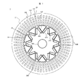
- FIG. 1 is a cross-sectional view of a permanent magnet type rotating electric machine according to an embodiment of the present invention, in a plane of rotation.
- the figure explaining the torque ripple reduction effect which concerns on one Embodiment of this invention. 1 is an external perspective view of a stator according to an embodiment of the present invention.
- FIG. 1 is a sectional view in the rotation plane of a permanent magnet type rotating electric machine 1 according to one embodiment.
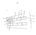
- FIG. 2 is an enlarged view of a cross section of the stator 10 according to one embodiment, and is an enlarged view of an X portion surrounded by a dotted line in FIG.
- the permanent magnet type rotating electric machine 1 of the present embodiment has a 10-pole 60 in which a substantially annular stator 10 is disposed on the outer peripheral side and a substantially cylindrical rotor 20 is disposed on the inner peripheral side. It is a slot distribution winding permanent magnet type rotating electric machine.
- An air gap 30 is provided between the stator 10 and the rotor 20.
- the stator 10 has a stator core 100 and a core back 110, a plurality of teeth 120, slots 130 and windings 140, and is arranged to face the rotor 20 via the air gap 30. .
- the stator 10 is formed, for example, as follows. First, a plurality of radial teeth 120 are formed on the inner peripheral side by a stator core laminated body in which integral punched cores of electromagnetic steel sheets are laminated, and slots 130 are formed between the teeth 120. Next, a plurality of segment coils are inserted into each of the slots 130 to form the windings 140, which are then shrink-fitted or press-fitted into a housing (not shown) to be integrated. Thus, the stator 10 is formed.
- the rotor 20 has a rotor core 200 that is an iron core formed by laminating electromagnetic steel sheets, and a shaft 300 that is a rotation axis.
- a rotor core 200 that is an iron core formed by laminating electromagnetic steel sheets
- a shaft 300 that is a rotation axis.
- ten magnetic pole portions 220 are provided in the circumferential direction.
- Each of the magnetic pole portions 220 is provided with a magnetic pole outer peripheral surface forming a surface facing the stator 10, and is provided with a V-shaped storage space 212 in which the permanent magnet 210 is stored. In the storage space 212, two rectangular permanent magnets 210 are inserted and arranged for each magnetic pole part 220.
- the winding 140 is formed by inserting four segment coils into each slot 130.
- reference numerals 140a, 140b, 140c, and 140d are assigned in order from the segment coil on the inner peripheral side.
- the teeth 120 face a segment coil (hereinafter, referred to as an “innermost segment coil”) 140 a arranged on the innermost side in the slot 130.
- the region 121 the region indicated by the solid arrow in the drawing
- the region 122 the figure shows the minimum tooth width.
- the innermost segment coil 140a has a shape different from the other segment coils 140b to 140d. That is, while the segment coils 140b to 140d have a rectangular cross section, the innermost peripheral segment coil 140a has two side surfaces 142a and 143a extending in the radial direction and portions 144a and 145a (in FIG. It is formed so as to have a shape having portions indicated by broken-line arrows) and portions 146a and 147a whose intervals are narrowed on the inner peripheral side (portions indicated by dashed-dotted arrows in the drawing). As described above, both side surfaces 142a and 143a of the innermost circumferential segment coil 140a have shapes along the side surfaces of the teeth 120 facing each other.
- the segment coils 140a to 140d are inserted into the slots 130 to form the windings 140
- the segment coils 140a and 140b are inserted first. Then, these segment coils 140a and 140b are pressed toward the inner peripheral side, that is, toward the distal end side of each tooth 120.
- the inner peripheral portions 146a and 147a of the both side surfaces 142a and 143a of the innermost peripheral segment coil 140a are brought into close contact with the side surfaces of the teeth 120 via insulating paper (not shown). Therefore, a gap necessary for inserting the remaining segment coils 140c and 140d into the respective slots 130 can be provided. Thereafter, the remaining segment coils 140c and 140d are inserted into the respective slots 130 to form the windings 140.
- the circumferential gap between the innermost segment coil 140a and the teeth 120 is smaller than the circumferential gap between the segment coil 140d and the teeth 120 arranged at the outermost periphery in the slot 130.
- the gap between the teeth 120 and the windings 140 is minimized. It is possible to increase the ratio of the winding 140 occupied therein, that is, the ratio of the segment coils 140a to 140d. As a result, the cross-sectional area of the winding 140 can be increased, and the resistance can be reduced.
- Comparative Example 1 is an example in which the sectional shapes of the segment coils 140a to 140d are all the same substantially rectangular.
- Comparative Example 2 is an example in which the cross-sectional shape of the two inner segment coil segments 140a and 140b is trapezoidal. In each of the embodiment and Comparative Examples 1 and 2, the sectional areas of all the segment coils 140a to 140d are assumed to be equal.
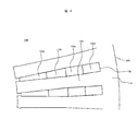
- FIG. 3 is an enlarged view of a cross section of the stator 10A according to the comparative example 1, and shows a portion corresponding to the enlarged view of the cross section of the stator 10 according to the embodiment shown in FIG.
- the cross-sections of the segment coils 140a to 140d are substantially the same and substantially rectangular, and the circumferential width of each of the slots 130 accommodating the same is determined at any position along the radial direction. But they are the same. Therefore, the width of the teeth 120 changes along the radial direction, and decreases from the outer peripheral side toward the inner peripheral side. That is, the tooth width in Comparative Example 1 is minimum at a position in contact with the inner peripheral end 141a of the innermost peripheral segment coil 140a.
- FIG. 4 is an enlarged view of a cross section of the stator 10B according to the comparative example 2, and shows a portion corresponding to the enlarged view of the cross section of the stator 10 according to the embodiment shown in FIG.
- the cross-sectional shape of the two inner segment coils 140a and 140b is trapezoidal, and the cross-sectional shape of the two outer segment coils 140c and 140d is substantially rectangular.
- the circumferential width of each of the slots 130 for accommodating them is narrower toward the inner circumferential side along the radial direction at a position corresponding to the segment coils 140a and 140b, and at a position corresponding to the segment coils 140c and 140d, It is constant along the radial direction.
- the width of the teeth 120 increases from the outer side to the inner side in the range along the segment coils 140a and 140b, and decreases from the outer side to the inner side in the range along the segment coils 140c and 140d. I do. That is, the tooth width in Comparative Example 2 is minimum at a position in contact with the boundary between the segment coil 140b and the segment coil 140c.
- FIG. 5 is a diagram illustrating the effect of reducing torque ripple according to one embodiment of the present invention.
- FIG. 5 shows a magnetic field analysis of torque and torque ripple in the permanent magnet type rotating electric machine 1 using the stator 10 according to the present embodiment, the stator 10A according to Comparative Example 1, and the stator 10B according to Comparative Example 2, respectively. Are shown as ratios where the magnitude of the torque and torque ripple in Comparative Example 1 are set to 1.
- the torque ripple can be reduced by about 10% with almost no change in the torque as compared with Comparative Example 1.
- the torque ripple can be further reduced, but the torque is reduced by about 20% compared to the present embodiment and the comparative example 1.
- the torque ripple can be reduced without lowering the torque as compared with Comparative Examples 1 and 2, it is suitable for reducing both the winding resistance and the torque ripple.
- the reason why the torque ripple is reduced as compared with the comparative example 1 is that the width of the teeth 120 is increased. That is, in the case of the present embodiment, as described with reference to FIG. 2, in the region 121 facing the innermost peripheral segment coil 140a and on the outer peripheral side of the inner peripheral end 141a of the innermost peripheral segment coil 140a. , The teeth width is minimized. For this reason, assuming that the sectional areas of the segment coils 140a to 140d are the same, the minimum tooth width of the present embodiment is larger than that of the comparative example 1.
- the radial length of the innermost circumferential segment coil 140a is increased as compared with the first comparative example, and the increase in the length is (BA) * ⁇ / N * (B -A) / W.
- W represents the slot width.
- Comparative Example 2 since the width of the teeth 120 is larger than in the present embodiment, the torque ripple is further reduced as described above. However, in Comparative Example 2, the radial length of the innermost circumferential segment coil 140a is significantly increased as compared with Comparative Example 1. Therefore, the radius of the rotor 20 is greatly reduced, which leads to a decrease in torque as described above.
- FIG. 4 shows an example in which the position in contact with the boundary between the segment coil 140b and the segment coil 140c is the minimum tooth width as Comparative Example 2, but the position in contact with the boundary between the segment coil 140a and the segment coil 140b, A similar problem occurs when the position in contact with the boundary between 140c and segment coil 140d is the minimum tooth width.
- the cross sections of the segment coils 140b to 140d excluding the innermost segment coil 140a can be made substantially rectangular as in Comparative Example 1, and the innermost segment coil 140a can also be formed. , The cross-sectional shape of which can be made nearly rectangular. Therefore, the same processing as in Comparative Example 1 can be performed on the segment coils 140a to 140d.
- an increase in the radial length of the cross section of the innermost circumferential segment coil 140a can be suppressed as compared with Comparative Example 2.
- the increase in the radial length can be kept to less than 10% as compared with the case of Comparative Example 1 in which the cross section of the innermost segment coil 140a is rectangular. it can. Even if the number of slots is different, the increase can be limited to about 20% at the maximum. For this reason, the problem of the film integrity at the time of processing as described above and the problem of the twistability of the end portion hardly occur, and the same processing as that of Comparative Example 1 can be performed. Furthermore, in the welding process of the segment coils performed after the end portion is twisted, the same workability as that of the segment coil having a rectangular cross section can be ensured. it can.
- the cross-sectional shape may be substantially rectangular.
- the cross section of the end portion where the twisting is performed can be made substantially rectangular, so that the same processing as that of Comparative Example 1 can be performed.
- the resistance of the winding 140 is reduced in this embodiment so that a large current can be used with a low-voltage power supply, the eddy current loss in the segment coils 140a to 140d does not need to be considered. . Therefore, there is no need to provide any gap other than that required for manufacturing between the segment coils 140a to 140d and the teeth 120 in the slot 120. Rather, it is not preferable to provide a useless gap in the slot 120, because this may hinder the lowering of the resistance of the winding 140.
- the inner circumferential portions 146a and 147a of the both side surfaces 142a and 143a of the innermost circumferential segment coil 140a are brought into close contact with the side surfaces of the teeth 120, respectively, so that extra The gap is reduced, and the winding resistance is reduced as much as possible.
- FIG. 6 is an external perspective view of the stator 10 according to one embodiment of the present invention.
- the stator 10 of the present embodiment has an annular stator core 100 and a wave-shaped winding 140 configured using the segment coils 140a to 140d described in FIG.
- the winding 140 includes a first system winding 141 and a second system winding 142.
- the first system winding 141 and the second system winding 142 electrically connect the terminal ends of a plurality of segment coils having a substantially U-shape corresponding to the segment coils 140a to 140d to each other at a connection portion 160. It is constituted by.
- As a connection method of the connection portion 160 solder, Tig welding, laser welding, or the like is used.
- the first system winding 141 includes two conductors arranged on the inner peripheral side of the stator core 100, that is, segment coils 140a and 140b.
- the second system winding 142 is composed of the remaining two conductors arranged on the outer peripheral side of the first system winding 141, that is, the segment coils 140c and 140d.
- An insulating member 170 is provided between these two system windings 141 and 142 in order to avoid mutual mechanical and electrical contact.
- a crossover 161 is connected to each of the first system winding 141 and the second system winding 142 as necessary.
- the first system winding 141 and the second system winding 142 are provided with a first system lead wire 151 and a second system winding lead wire 153 connected to an inverter (not shown).
- the first system lead wire 151 is on the right side of FIG. Each of them is collectively arranged on the left side of FIG.
- the first system lead wire 151 and the second system winding 142 have a winding start side and a winding end side for each of the three phase windings, and both of them have the same axial side in the stator core 100.
- the stator 10 capable of sufficiently reducing the winding resistance and the torque ripple and the permanent magnet type rotating electric machine 1 using the same can be realized.
- the power supply power can be effectively used by reducing the winding resistance, and the vibration and noise propagating in the vehicle cabin can be suppressed.
- the present invention to other electric auxiliary equipment for automobiles, for example, an electric auxiliary equipment for automobile that performs electric braking, it is possible to reduce vibration and suppress noise and vibration.
- the application of the permanent magnet type rotating electric machine 1 of the present embodiment is not limited to the field of automobiles, but can be applied to all industrial permanent magnet type rotating electric machines in which low resistance and low vibration are preferable.
- the stator 10 has a stator core 100 provided with a plurality of teeth 120, and a plurality of segment coils 140a to 140d inserted into slots 130 formed between the teeth 120.
- the teeth 120 are located in a region 121 of the plurality of segment coils 140a to 140d facing the innermost peripheral segment coil 140a disposed in the innermost periphery in the slot 130 and on the inner peripheral side of the innermost peripheral segment coil 140a.
- a portion 122 having a minimum tooth width is provided on the outer peripheral side of the end portion 141a.
- Both side surfaces 142a and 143a along the radial direction of the innermost segment coil 140a have portions 144a and 145a parallel to each other and portions 146a and 147a whose intervals are reduced on the inner circumferential side. With this configuration, the winding resistance and the torque ripple can be sufficiently reduced.
- the side surfaces 142a and 143a of the innermost segment coil 140a have shapes along the side surfaces of the teeth 120 facing each other.
- the portions 146a, 147a of which the intervals are reduced on the inner peripheral side of both side surfaces 142a, 143a along the radial direction of the innermost peripheral segment coil 140a are in close contact with the side surfaces of the teeth 120 via insulating paper.
- the circumferential gap between the innermost segment coil 140a and the tooth 120 is equal to the distance between the outermost segment coil 140d and the tooth 120, which are arranged on the outermost periphery in the slot 130 among the plurality of segment coils 140a to 140d. Smaller than the gap in the direction. Because of this, the segment coils 140a and 140b arranged on the inner peripheral side are inserted into each slot 130, and then the remaining segment coils 140c and 140d are inserted into each slot 130 to form the winding 140. it can.
- the sectional areas of the plurality of segment coils 140a to 140d are equal to each other. With this configuration, the winding resistance of each phase can be made uniform.
- the permanent magnet type rotating electric machine 1 is configured using the stator 10 described above. With this configuration, it is possible to realize a rotating electric machine with sufficiently reduced winding resistance and torque ripple.
- the permanent magnet type rotating electric machine 1 as described above may be provided, and using the permanent magnet type rotating electric machine 1, an electric auxiliary machine system for an automobile that performs electric power steering or electric braking may be configured. In this way, it is possible to realize an automobile electric accessory system in which power and electric power are effectively used and vibration and noise are suppressed.
- the permanent magnet type rotary electric machine 1 having 10 poles and 60 slots distributed winding has been described as an example.
- the present invention can be applied to a rotary electric machine having other poles and slots. That is, for a rotating electric machine having an arbitrary number of poles and slots, the winding resistance and the torque ripple can be sufficiently reduced according to the configuration of the stator described in the present embodiment.
Landscapes
- Engineering & Computer Science (AREA)
- Power Engineering (AREA)
- Iron Core Of Rotating Electric Machines (AREA)
- Windings For Motors And Generators (AREA)
Abstract
本発明の課題は、回転電機における巻線抵抗とトルクリプルを十分に低減することである。 本発明の固定子10は、複数のティース120が設けられた固定子コア100と、ティース120間に形成されるスロット130に挿入された複数のセグメントコイル140a~140dとを有する。ティース120は、複数のセグメントコイル140a~140dのうちスロット130内で最内周に配置された最内周セグメントコイル140aと対向する領域121内で、かつ、最内周セグメントコイル140aの内周側端部141aよりも外周側に、ティース幅が最小となる部位122を有する。最内周セグメントコイル140aの径方向に沿った両側面142a、143aは、互いに平行な部位144a、145aと、内周側で間隔が狭まる部位146a、147aとを有する。
Description
本発明は、固定子と、これを用いた回転電機および自動車用電動補機システムとに関する。
近年の自動車は、油圧システムから電動システムへの移行や、ハイブリッド自動車、電気自動車の市場拡大の流れを受けて、電動パワーステアリング(以下、EPS)装置や電動ブレーキ装置の装着率が急速に増大している。また、アイドリングストップやブレーキなどの運転操作の一部を自動化した車の普及を背景に、運転快適性の向上とともに車室内の静音化が進展している。
車室内の振動、騒音に繋がる電気モータ起因の加振源としては、電気モータのトルク変動成分(コギングトルクやトルクリプル)と、電気モータのステータと回転子の間に発生する電磁加振力がある。これらのうちトルク変動成分による振動エネルギーは、電気モータの出力軸を介して車室内へ伝搬し、また、電磁加振力による振動エネルギーは、EPS装置の機械部品などを介して車室内へ伝搬する。これらの振動エネルギーが車室内へ伝搬することで、車室内の振動、騒音に繋がっている。
例えば、EPS装置では、電気モータがステアリングホイール操作をアシストすることから、運転者はステアリングホイールを介して、電気モータのコギングトルクやトルクリプルを手に感じることになる。これを抑制するため、EPS装置に用いる電気モータでは、一般にコギングトルクをアシストトルクの1/1000未満に、トルクリプルをアシストトルクの1/100未満に抑制することが求められる。また、電磁加振力の空間モードの最小次数が2以下でないことがよいとされる。
ここで、電気モータの出力は、(磁気回路に作用する電圧)×(電流)に比例する。そのため、低電圧電源で駆動されるEPS装置においては、損失低減のために巻線の低抵抗化が求められる。サイズの制約上、モータ外径を変えずに巻線を低抵抗化する場合は、モータ軸長の低減による巻線長の低減と、巻線径(巻線断面積)の増加との少なくとも一つが必要となる。
EPS装置では、ハンドル急操作時には電気モータの回転数が増加し、磁石磁束による誘起電圧が増加することで、磁気回路に作用する電圧が小さくなる。このときにトルクが小さくなりすぎるのを防ぐ方法として、一般的には弱め界磁制御が用いられる。すなわち、高回転時には弱め界磁制御を行って磁石磁束を打ち消すことにより、磁気回路に作用する電圧を残して電気モータの出力を維持する。弱め界磁制御を行うためには、巻線が磁石磁束を打ち消すのに十分なd軸インダクタンスを有する必要があるが、インダクタンスは軸長×巻数2に比例するため、巻線長の低減のためにモータ軸長を低減すると、十分なd軸インダクタンスが得られなくなってしまう。したがって、EPS装置において巻線の低抵抗化を達成するには、巻線径(巻線断面積)の増加が必要となる。
略矩形断面を有する電線を用いて分布巻線が構成された電気モータにおいては、巻線断面積は巻線の周方向幅×径方向幅にほぼ等しい。周方向幅を増加して巻線断面積を増加する場合、巻線の周方向幅を増加させた分だけティース幅を減少させる必要がある。すなわち、巻線断面積を増加すると、その分だけティース幅が減少する。ティース幅が減少すると磁気飽和が生じやすくなるため、トルクリプルが増加する傾向がある。したがってEP装置に用いられる電気モータでは、巻線を低抵抗化しつつ、トルクリプルの増加を抑制することが重要である。
電気モータにおける巻線抵抗とトルクリプルの低減に関して、特許文献1の技術が知られている。特許文献1には、環状部と該環状部から径方向に延びる複数のティースとを有する電機子コアと、前記ティース間のスロットに軸方向に貫通するように設けられる複数のセグメント導体同士が電気的に接続されて構成されるセグメント巻線とを備えたステータであって、前記ティースは、前記スロットの径方向と直交する方向の幅を径方向内側ほど狭くする幅調整部を有したことを特徴とするステータが開示されている。
特許文献1に開示されたステータでは、巻線抵抗とトルクリプルの低減に関して改良の余地が多く残されている。
本発明による固定子は、複数のティースが設けられた固定子コアと、前記ティース間に形成されるスロットに挿入された複数のセグメントコイルとを有するものであって、前記ティースは、前記複数のセグメントコイルのうち前記スロット内で最内周に配置された最内周セグメントコイルと対向する領域内で、かつ、前記最内周セグメントコイルの内周側端部よりも外周側に、ティース幅が最小となる部位を有し、前記最内周セグメントコイルの径方向に沿った両側面は、互いに平行な部位と、内周側で間隔が狭まる部位とを有する。
本発明による回転電機は、上記の固定子を用いたものである。
本発明による自動車用電動補機システムは、上記の回転電機を備え、前記回転電機を用いて、電動パワーステアリングまたは電動ブレーキを行う。
本発明による回転電機は、上記の固定子を用いたものである。
本発明による自動車用電動補機システムは、上記の回転電機を備え、前記回転電機を用いて、電動パワーステアリングまたは電動ブレーキを行う。
本発明によれば、巻線抵抗とトルクリプルを十分に低減することができる。
本発明の実施例について、適宜図面を参照しながら詳細に説明する。なお、各図面において、同様の構成要素については、同一の符号を付して説明を省略する。
図1と図2を用いて、本発明の一実施形態に係る回転子を備えた永久磁石式回転電機1の構成を説明する。図1は、一実施形態に係る永久磁石式回転電機1の回転面内断面図である。図2は、一実施形態に係る固定子10の断面の拡大図であり、図1の点線で囲ったX部を拡大して示した図である。
図1に示すように、本実施形態の永久磁石式回転電機1は、外周側に略環状の固定子10を配置し、内周側に略円柱状の回転子20を配置した、10極60スロット分布巻の永久磁石式回転電機である。固定子10と回転子20の間にはエアギャップ30が設けられている。固定子10は、固定子コア100およびコアバック110と、複数のティース120、スロット130および巻線140とを有しており、エアギャップ30を介して回転子20と対向して配置されている。
固定子10は、例えば次のようにして形成される。まず、電磁鋼板の一体打ち抜きコアを積層したステータコア積層体により、内周側に放射状のティース120を複数形成するとともに、各ティース120間にスロット130を形成する。次に、各スロット130に複数のセグメントコイルを挿入して巻線140を形成した後、図示しないハウジングに焼嵌めまたは圧入して一体化する。このようにして、固定子10が形成される。
また、図1に示すように、回転子20は、電磁鋼板を積層した鉄心である回転子コア200と、回転軸となるシャフト300とを有する。回転子コア200の外周には、周方向に10極の磁極部220が設けられている。磁極部220の各々は、固定子10との対向面を形成する磁極外周面が設けられるとともに、永久磁石210が収納されるV字形の収納空間212が設けられている。収納空間212には、矩形の永久磁石210が各磁極部220について2個ずつ挿入されて配置されている。
図1および図2に示すように、本実施形態の固定子10では、各スロット130内に4つのセグメントコイルが挿入されることで巻線140が形成される。図2では、内周側のセグメントコイルから順に、140a、140b、140c、140dの符号を付している。図2に示すように、本実施形態の固定子10において、ティース120は、スロット130内で最も内周側に配置されたセグメントコイル(以下では「最内周セグメントコイル」と称する)140aと対向する領域121(図中に実線矢印で示した領域)内で、かつ、最内周セグメントコイル140aの内周側端部141aよりも外周側に、ティース幅が最小となる部位122(図中に破線で囲って示した範囲)が設けられている。また、このようなティース120の形状に対応して、最内周セグメントコイル140aは、他のセグメントコイル140b~140dとは異なる形状を有している。すなわち、セグメントコイル140b~140dは断面が矩形形状であるのに対して、最内周セグメントコイル140aは、径方向に沿った両側面142a、143aが、互いに平行な部位144a、145a(図中に破線矢印で示した部位)と、内周側で間隔が狭まる部位146a、147a(図中に一点鎖線矢印で示した部位)とを有する形状となるように形成されている。このように、最内周セグメントコイル140aの両側面142a、143aは、対向するティース120の側面にそれぞれ沿った形状を有している。
なお、各スロット130にセグメントコイル140a~140dを挿入して巻線140を形成する際には、最初にセグメントコイル140a、140bを挿入する。そして、これらのセグメントコイル140a、140bを内周側、すなわち各ティース120の先端側に向かって押し付けるようにする。これにより、最内周セグメントコイル140aの両側面142a、143aにおける内周側の部位146a、147aは、図示しない絶縁紙を介してティース120の側面にそれぞれ密着される。したがって、残りのセグメントコイル140c、140dを各スロット130に挿入する際に必要な隙間を設けることができる。その後、残りのセグメントコイル140c、140dを各スロット130に挿入して、巻線140を形成する。このとき、最内周セグメントコイル140aとティース120との周方向の隙間は、スロット130内で最外周に配置されたセグメントコイル140dとティース120との周方向の隙間より小さくなる。
本実施形態の固定子10では、上記のようにしてセグメントコイル140a~140dをスロット130に挿入して巻線140を形成することで、ティース120と巻線140との隙間を最小化し、スロット130内に占める巻線140の割合、すなわちセグメントコイル140a~140dの割合を増加することができる。その結果、巻線140の断面積を増加し、低抵抗化を図ることができる。
ここで、本実施形態の固定子10における巻線抵抗とトルクリプルの低減効果について、以下に比較例1、2と対比して説明する。比較例1は、セグメントコイル140a~140dの断面形状を全て同一の略矩形とした場合の例である。比較例2は、内周側の2つのセグメントコイル140a、140bの断面形状を台形とした場合の例である。なお、本実施形態および比較例1、2いずれの場合も、全てのセグメントコイル140a~140dの断面積は等しいものとする。
図3は、比較例1による固定子10Aの断面の拡大図であり、図2に示した一実施形態に係る固定子10の断面の拡大図に対応する部分を示している。図3に示すように、比較例1では、セグメントコイル140a~140dの断面がいずれも同一の略矩形であり、これらを収容する各スロット130の周方向の幅は、径方向に沿ったどの位置でも同一である。そのため、ティース120の幅は径方向に沿って変化し、外周側から内周側に向かうほど減少する。すなわち、比較例1におけるティース幅は、最内周セグメントコイル140aの内周側端部141aに接する位置において最小となる。
図4は、比較例2による固定子10Bの断面の拡大図であり、図2に示した一実施形態に係る固定子10の断面の拡大図に対応する部分を示している。図4に示すように、比較例2では、内周側の2つのセグメントコイル140a、140bの断面形状が台形であり、外周側の2つのセグメントコイル140c、140dの断面形状が略矩形である。これらを収容する各スロット130の周方向の幅は、セグメントコイル140a、140bに対応する位置では、径方向に沿って内周側に向かうほど狭くなり、セグメントコイル140c、140dに対応する位置では、径方向に沿って一定である。そのため、ティース120の幅は、セグメントコイル140a、140bに沿った範囲では外周側から内周側に向かって増加し、セグメントコイル140c、140dに沿った範囲では外周側から内周側に向かって減少する。すなわち、比較例2におけるティース幅は、セグメントコイル140bとセグメントコイル140cの境界に接する位置において最小となる。
図5は、本発明の一実施形態に係るトルクリプルの低減効果を説明する図である。図5では、本実施形態に係る固定子10と、比較例1に係る固定子10Aと、比較例2に係る固定子10Bとをそれぞれ用いた永久磁石式回転電機1におけるトルクおよびトルクリプルを磁場解析により計算した結果を、比較例1でのトルクおよびトルクリプルの大きさを1とした比でそれぞれ示している。
図5に示されるように、本実施形態では、比較例1に対してトルクがほぼ変化せずに、トルクリプルを10%程度低減することができる。一方、比較例2ではトルクリプルをさらに低減することが可能であるが、本実施形態および比較例1に対してトルクが20%程度低減してしまう。このように、本実施形態によれば、比較例1、2と比べて、トルクを低下せずにトルクリプルを減少させることができるため、巻線抵抗とトルクリプルをともに低減させる上で好適である。
なお、本実施形態において比較例1よりもトルクリプルが低減するのは、ティース120の幅が増加するためである。すなわち、本実施形態の場合は、図2で説明したように、最内周セグメントコイル140aと対向する領域121内で、かつ、最内周セグメントコイル140aの内周側端部141aよりも外周側に位置する部位122において、ティース幅が最小となる。このため、セグメントコイル140a~140dの断面積が同一であるとすると、本実施形態の最小ティース幅は、比較例1の場合よりも増加する。比較例1における最小ティース幅の位置、すなわち内周側端部141aの回転中心からの半径をAとし、本実施形態における最小ティース幅の位置、すなわち部位122の回転中心からの半径をBとすると、比較例1に対する本実施形態の最小ティース幅の増加分は、(B-A)*2π/Nで表される。ここで、Nはスロット数を表している。
本実施形態では、前述のようにスロット数がN=60である。そのため、上記で計算される最小ティース幅の増加分は、(B-A)の約10%になる。このように、本実施形態では比較例1と比べて最小ティース幅を増加させることができるため、トルクリプルの低減が可能である。
また、本実施形態では、最内周セグメントコイル140aの径方向の長さが比較例1と比べて増加するが、この長さの増加分は、(B-A)*π/N*(B-A)/Wで近似できる。ここで、Wはスロット幅を表している。この長さの増加分を回転子20の半径の減少分に換算すると、これは1%に満たない程度の値である。したがって、本実施形態での比較例1に対するトルク低下分は、上記の最小ティース幅の増加によるトルク増加分と相殺され、無視できる程度になると考えられる。
一方、比較例2ではティース120の幅が本実施形態よりも増加するため、前述のようにトルクリプルがさらに低下する。しかしながら、比較例2では比較例1と比べて、最内周セグメントコイル140aの径方向の長さが大きく増加する。そのため、回転子20の半径が大きく減少し、前述のようなトルクの低下につながる。
また、比較例2の場合は、セグメントコイル140aおよび140bの断面が径方向に細長い台形形状であるため、加工時に被膜健全性が損なわれやすいという問題もある。さらに、スロット130への挿入後に行われる末端部の捻り加工時には、内周側により大きな力を加える必要があるため、断面が矩形形状のセグメントコイル140c、140dとは同様の加工工程を採用できないという問題もある。これらの問題は、特に最内周セグメントコイル140aについて顕著に生じる。したがって、比較例2におけるセグメントコイル140aおよび140bのように、断面が径方向に細長い台形形状の巻線を採用するのは、巻線抵抗の低減に関して好ましくない。なお、図4では比較例2として、セグメントコイル140bとセグメントコイル140cの境界に接する位置を最小ティース幅とした例を示したが、セグメントコイル140aとセグメントコイル140bの境界に接する位置や、セグメントコイル140cとセグメントコイル140dの境界に接する位置を最小ティース幅とした場合でも、同様の問題が生じる。
一方、本実施形態の場合は、最内周セグメントコイル140aを除いたセグメントコイル140b~140dの断面を、比較例1と同様に略矩形とすることができるとともに、最内周セグメントコイル140aについても、その断面形状を矩形に近いものとすることができる。したがって、セグメントコイル140a~140dに対して、比較例1と同様の加工が可能となる。
以上説明したように、本実施形態に係る固定子10の構成を採用した永久磁石式回転電機1によれば、巻線抵抗とトルクリプルを十分に小さくできることが分かる。
また、本実施形態においては、比較例2と比べて、最内周セグメントコイル140aの断面の径方向長さの増加を抑えることができる。本実施形態では、スロット数がN=60であるため、最内周セグメントコイル140aの断面が矩形である比較例1の場合と比べて、径方向長さの増加を10%未満に留めることができる。なお、スロット数が異なる場合でも、最大で20%程度の増加に留めることができる。このため、前述のような加工時における被膜健全性の問題や、末端部の捻り加工性の問題が生じにくく、比較例1と同様の加工が可能である。さらに、末端部の捻り加工後に行われるセグメントコイル同士の溶接工程においても、断面が矩形形状のセグメントコイルと同様の作業性を確保できるため、比較例1と同様の製造のしやすさとすることができる。
さらに、本実施形態においては、最内周セグメントコイル140aのうち、スロット130内に配置される部分の断面のみを図2のような形状に成形し、スロット130の外に配置される部分については他のセグメントコイル140b~140dと同様に、断面形状を略矩形とすることもできる。このようにすれば、捻り加工を行う末端部の断面を略矩形とすることができるため、比較例1と同様の加工が可能となる。
なお、本実施形態における巻線140の低抵抗化は、低電圧電源で大電流を使用できるようにするためのものであるため、セグメントコイル140a~140dにおける渦電流損は考慮しなくてもよい。そのため、スロット120内においてセグメントコイル140a~140dとティース120の間には、製造上必要な隙間以外を設ける必要がない。むしろ、スロット120内に無駄な隙間を設けることは、巻線140の低抵抗化の障害となるため好ましくない。したがって、本実施形態では前述のように、最内周セグメントコイル140aの両側面142a、143aにおける内周側の部位146a、147aをティース120の側面にそれぞれ密着させることで、スロット130内の余分な隙間を削減し、巻線抵抗を可能な限り低減している。
次に、本実施形態の固定子10における立体的な巻線構造について、図6を参照して説明する。図6は、本発明の一実施形態に係る固定子10の外観斜視図である。
本実施形態の固定子10は、円環状の固定子コア100と、図2で説明したセグメントコイル140a~140dを用いて構成された波巻状の巻線140とを有している。この巻線140は、図6で示すように、第1系統巻線141および第2系統巻線142で構成される。第1系統巻線141および第2系統巻線142は、セグメントコイル140a~140dに相当して略U字形状を有する複数のセグメントコイルの末端側を、接続部160で電気的に相互に接続することにより構成されている。接続部160の接続方式としては、半田やTig溶接、レーザー溶接等が用いられる。
図2で説明したように、固定子コア100に形成された各スロット130内には、セグメントコイル140a~140dとして4本の導体が設置されている。第1系統巻線141は、固定子コア100の内周側に配置された2本の導体、すなわちセグメントコイル140aおよび140bで構成されている。また、第2系統巻線142は、第1系統巻線141の外周側に配置された残りの2本の導体、すなわちセグメントコイル140cおよび140dで構成されている。これら2つの系統巻線141、142の間には、機械的および電気的な相互の接触を避けるため、絶縁部材170が設けられている。また、第1系統巻線141および第2系統巻線142には、必要に応じて渡り線161がそれぞれ接続されている。
第1系統巻線141と第2系統巻線142には、不図示のインバータに接続される第1系統口出し線151と第2系統巻線口出し線153がそれぞれ設けられている。本実施形態では、第1系統巻線141と第2系統巻線142の機械的な接触を避けるために、第1系統口出し線151は図6の右側に、第2系統巻線口出し線153は図6の左側に、それぞれまとめて配置されている。第1系統口出し線151および第2系統巻線142は、3相分の巻線のそれぞれについて巻始め側と巻終わり側を有しており、そのどちらも固定子コア100において軸方向で同じ側に配置されている。本実施形態の固定子10を用いて永久磁石式回転電機1を構成する場合には、不図示のリレーにより、第1系統口出し線151および第2系統巻線142における巻終わり側の3相分を互いに電気的に接続して中性点を設けることが好ましい。これにより、永久磁石式回転電機1の内部で電気的な短絡が発生した場合には、中性点のリレーを切り離して電気的な短絡によるブレーキトルクの発生を防止することができる。
以上説明したように、本実施形態の構成によれば、巻線抵抗とトルクリプルを十分に低減可能な固定子10およびこれを用いた永久磁石式回転電機1を実現することができる。
なお、本実施形態の永久磁石式回転電機1をEPS装置に用いることで、巻線抵抗の低減により電源電力を有効利用するとともに、車室内に伝搬する振動や騒音を抑制できる。また、その他の自動車用電動補機装置、たとえば電動ブレーキを行う自動車用電動補機装置に適用することでも、低抵抗化とともに、振動や騒音を抑制することが可能である。さらには、本実施形態の永久磁石式回転電機1の採用は自動車分野に限定されず、低抵抗化や低振動化が好ましい産業用の永久磁石式回転電機全般にも適用可能である。
以上説明した本発明の実施形態によれば、以下の作用効果を奏する。
(1)固定子10は、複数のティース120が設けられた固定子コア100と、ティース120間に形成されるスロット130に挿入された複数のセグメントコイル140a~140dとを有する。ティース120は、複数のセグメントコイル140a~140dのうちスロット130内で最内周に配置された最内周セグメントコイル140aと対向する領域121内で、かつ、最内周セグメントコイル140aの内周側端部141aよりも外周側に、ティース幅が最小となる部位122を有する。最内周セグメントコイル140aの径方向に沿った両側面142a、143aは、互いに平行な部位144a、145aと、内周側で間隔が狭まる部位146a、147aとを有する。このようにしたので、巻線抵抗とトルクリプルを十分に低減することができる。
(2)最内周セグメントコイル140aの側面142a、143aは、対向するティース120の側面に沿った形状をそれぞれ有する。最内周セグメントコイル140aの径方向に沿った両側面142a、143aの内周側で間隔が狭まる部位146a、147aは、絶縁紙を介してティース120の側面にそれぞれ密着している。このようにしたので、スロット130内に占める巻線140の割合を可能な限り大きくして、巻線抵抗を十分に低減することができる。
(3)最内周セグメントコイル140aとティース120との周方向の隙間は、複数のセグメントコイル140a~140dのうちスロット130内で最外周に配置された最外周セグメントコイル140dとティース120との周方向の隙間より小さい。このようにしたので、内周側に配置されるセグメントコイル140a、140bを各スロット130に挿入後、残りのセグメントコイル140c、140dを各スロット130に挿入して、巻線140を形成することができる。
(4)固定子10は、複数のセグメントコイル140a~140dの断面積が互いに等しい。このようにしたので、各相の巻線抵抗を均一にすることができる。
(5)永久磁石式回転電機1は、上記の固定子10を用いて構成される。このようにしたので、巻線抵抗とトルクリプルを十分に低減した回転電機を実現できる。
(6)上記のような永久磁石式回転電機1を備え、この永久磁石式回転電機1を用いて、電動パワーステアリングまたは電動ブレーキを行う自動車用電動補機システムを構成してもよい。このようにすれば、電源電力を有効利用するとともに、振動や騒音を抑制した自動車用電動補機システムを実現できる。
なお、本実施形態では10極60スロット分布巻の永久磁石式回転電機1を例として説明したが、他の極数やスロット数の分布巻の回転電機においても、本発明を適用可能である。すなわち、任意の極数およびスロット数の回転電機について、本実施形態で説明した固定子の構成にしたがって、巻線抵抗とトルクリプルを十分に低減可能である。
以上説明した実施形態や各種変形例はあくまで一例であり、発明の特徴が損なわれない限り、本発明はこれらの内容に限定されるものではない。また、上記では種々の実施形態や変形例を説明したが、本発明はこれらの内容に限定されるものではない。本発明の技術的思想の範囲内で考えられるその他の態様も本発明の範囲内に含まれる。
1 永久磁石式回転電機
10 固定子
20 回転子
30 エアギャップ
100 固定子コア
110 コアバック
120 ティース
130 スロット
140 巻線
140a,140b,140c,140d セグメントコイル
200 回転子コア
210 永久磁石
212 収納空間
220 磁極部
300 シャフト
10 固定子
20 回転子
30 エアギャップ
100 固定子コア
110 コアバック
120 ティース
130 スロット
140 巻線
140a,140b,140c,140d セグメントコイル
200 回転子コア
210 永久磁石
212 収納空間
220 磁極部
300 シャフト
Claims (6)
- 複数のティースが設けられた固定子コアと、前記ティース間に形成されるスロットに挿入された複数のセグメントコイルとを有する固定子であって、
前記ティースは、前記複数のセグメントコイルのうち前記スロット内で最内周に配置された最内周セグメントコイルと対向する領域内で、かつ、前記最内周セグメントコイルの内周側端部よりも外周側に、ティース幅が最小となる部位を有し、
前記最内周セグメントコイルの径方向に沿った両側面は、互いに平行な部位と、内周側で間隔が狭まる部位とを有する固定子。 - 請求項1に記載の固定子において、
前記最内周セグメントコイルの側面は、対向する前記ティースの側面に沿った形状をそれぞれ有し、
前記最内周セグメントコイルの径方向に沿った両側面の前記内周側で間隔が狭まる部位は、絶縁紙を介して前記ティースの側面にそれぞれ密着している固定子。 - 請求項2に記載の固定子において、
前記最内周セグメントコイルと前記ティースとの周方向の隙間は、前記複数のセグメントコイルのうち前記スロット内で最外周に配置された最外周セグメントコイルと前記ティースとの周方向の隙間より小さい固定子。 - 請求項1から請求項3のいずれか一項に記載の固定子において、
前記複数のセグメントコイルの断面積が互いに等しい固定子。 - 請求項1から請求項4のいずれか一項に記載の固定子を用いた回転電機。
- 請求項5に記載の回転電機を備え、
前記回転電機を用いて、電動パワーステアリングまたは電動ブレーキを行う自動車用電動補機システム。
Applications Claiming Priority (2)
| Application Number | Priority Date | Filing Date | Title |
|---|---|---|---|
| JP2018-151281 | 2018-08-10 | ||
| JP2018151281A JP2020028166A (ja) | 2018-08-10 | 2018-08-10 | 固定子、回転電機、自動車用電動補機システム |
Publications (1)
| Publication Number | Publication Date |
|---|---|
| WO2020031610A1 true WO2020031610A1 (ja) | 2020-02-13 |
Family
ID=69415513
Family Applications (1)
| Application Number | Title | Priority Date | Filing Date |
|---|---|---|---|
| PCT/JP2019/027635 Ceased WO2020031610A1 (ja) | 2018-08-10 | 2019-07-12 | 固定子、回転電機、自動車用電動補機システム |
Country Status (2)
| Country | Link |
|---|---|
| JP (1) | JP2020028166A (ja) |
| WO (1) | WO2020031610A1 (ja) |
Families Citing this family (1)
| Publication number | Priority date | Publication date | Assignee | Title |
|---|---|---|---|---|
| JP7472631B2 (ja) * | 2020-04-28 | 2024-04-23 | 株式会社デンソー | 回転電機及びその製造方法 |
Citations (2)
| Publication number | Priority date | Publication date | Assignee | Title |
|---|---|---|---|---|
| JP2012016140A (ja) * | 2010-06-30 | 2012-01-19 | Denso Corp | 回転電機の固定子及びその製造方法 |
| JP2013158105A (ja) * | 2012-01-27 | 2013-08-15 | Denso Corp | 回転電機の固定子 |
-
2018
- 2018-08-10 JP JP2018151281A patent/JP2020028166A/ja active Pending
-
2019
- 2019-07-12 WO PCT/JP2019/027635 patent/WO2020031610A1/ja not_active Ceased
Patent Citations (2)
| Publication number | Priority date | Publication date | Assignee | Title |
|---|---|---|---|---|
| JP2012016140A (ja) * | 2010-06-30 | 2012-01-19 | Denso Corp | 回転電機の固定子及びその製造方法 |
| JP2013158105A (ja) * | 2012-01-27 | 2013-08-15 | Denso Corp | 回転電機の固定子 |
Also Published As
| Publication number | Publication date |
|---|---|
| JP2020028166A (ja) | 2020-02-20 |
Similar Documents
| Publication | Publication Date | Title |
|---|---|---|
| EP1253701B1 (en) | Motor | |
| JP6222032B2 (ja) | 回転電機 | |
| US8653714B2 (en) | Stator for electric rotating machine | |
| US20170288517A1 (en) | Brushless motor | |
| CN110492630B (zh) | 旋转电机 | |
| WO2012063684A1 (ja) | 回転電機 | |
| CN109478814B (zh) | 旋转电机的定子和旋转电机 | |
| JP6048191B2 (ja) | マルチギャップ型回転電機 | |
| JP2018133850A (ja) | 回転電機 | |
| JPWO2019003561A1 (ja) | 回転電機の固定子、及び回転電機 | |
| JP5893191B1 (ja) | 車両用回転電機 | |
| WO2022107404A1 (ja) | ロータ及び回転機 | |
| US20180248453A1 (en) | Rotor, Rotating Electric Machine Including Said Rotor, and Method of Manufacturing Said Rotor | |
| JP2013207946A (ja) | 回転電機 | |
| US20190131840A1 (en) | Rotary Electric Machine | |
| JP2014093914A (ja) | ブラシレスモータ | |
| WO2020031610A1 (ja) | 固定子、回転電機、自動車用電動補機システム | |
| CN114552836A (zh) | 旋转电机 | |
| JP2002191157A (ja) | 永久磁石併用同期回転機 | |
| JP2010154648A (ja) | モータ | |
| JP2014082935A (ja) | 回転電機の固定子、およびこれを備えた回転電機 | |
| JP3790765B2 (ja) | 永久磁石回転電機および永久磁石回転電機を用いた電動車両 | |
| JP2005130627A (ja) | 埋込磁石形同期電動機 | |
| WO2020262246A1 (ja) | モータ | |
| JP7852525B2 (ja) | モータの支持構造 |
Legal Events
| Date | Code | Title | Description |
|---|---|---|---|
| 121 | Ep: the epo has been informed by wipo that ep was designated in this application |
Ref document number: 19846476 Country of ref document: EP Kind code of ref document: A1 |
|
| NENP | Non-entry into the national phase |
Ref country code: DE |
|
| 122 | Ep: pct application non-entry in european phase |
Ref document number: 19846476 Country of ref document: EP Kind code of ref document: A1 |