WO2020031604A1 - すべり支承 - Google Patents
すべり支承 Download PDFInfo
- Publication number
- WO2020031604A1 WO2020031604A1 PCT/JP2019/027374 JP2019027374W WO2020031604A1 WO 2020031604 A1 WO2020031604 A1 WO 2020031604A1 JP 2019027374 W JP2019027374 W JP 2019027374W WO 2020031604 A1 WO2020031604 A1 WO 2020031604A1
- Authority
- WO
- WIPO (PCT)
- Prior art keywords
- piston plate
- synthetic resin
- annular groove
- sliding bearing
- elastic member
- Prior art date
- Legal status (The legal status is an assumption and is not a legal conclusion. Google has not performed a legal analysis and makes no representation as to the accuracy of the status listed.)
- Ceased
Links
Images

Classifications
-
- F—MECHANICAL ENGINEERING; LIGHTING; HEATING; WEAPONS; BLASTING
- F16—ENGINEERING ELEMENTS AND UNITS; GENERAL MEASURES FOR PRODUCING AND MAINTAINING EFFECTIVE FUNCTIONING OF MACHINES OR INSTALLATIONS; THERMAL INSULATION IN GENERAL
- F16F—SPRINGS; SHOCK-ABSORBERS; MEANS FOR DAMPING VIBRATION
- F16F15/00—Suppression of vibrations in systems; Means or arrangements for avoiding or reducing out-of-balance forces, e.g. due to motion
- F16F15/02—Suppression of vibrations of non-rotating, e.g. reciprocating systems; Suppression of vibrations of rotating systems by use of members not moving with the rotating systems
- F16F15/021—Decoupling of vibrations by means of point-of-contact supports, e.g. ball bearings
-
- E—FIXED CONSTRUCTIONS
- E01—CONSTRUCTION OF ROADS, RAILWAYS, OR BRIDGES
- E01D—CONSTRUCTION OF BRIDGES, ELEVATED ROADWAYS OR VIADUCTS; ASSEMBLY OF BRIDGES
- E01D19/00—Structural or constructional details of bridges
- E01D19/04—Bearings; Hinges
-
- F—MECHANICAL ENGINEERING; LIGHTING; HEATING; WEAPONS; BLASTING
- F16—ENGINEERING ELEMENTS AND UNITS; GENERAL MEASURES FOR PRODUCING AND MAINTAINING EFFECTIVE FUNCTIONING OF MACHINES OR INSTALLATIONS; THERMAL INSULATION IN GENERAL
- F16F—SPRINGS; SHOCK-ABSORBERS; MEANS FOR DAMPING VIBRATION
- F16F15/00—Suppression of vibrations in systems; Means or arrangements for avoiding or reducing out-of-balance forces, e.g. due to motion
- F16F15/02—Suppression of vibrations of non-rotating, e.g. reciprocating systems; Suppression of vibrations of rotating systems by use of members not moving with the rotating systems
- F16F15/04—Suppression of vibrations of non-rotating, e.g. reciprocating systems; Suppression of vibrations of rotating systems by use of members not moving with the rotating systems using elastic means
Definitions
- the present invention relates to a slide bearing that is disposed between two structures and that allows relative rotation and relative displacement of the two structures.
- a sliding bearing disposed between one structure and the other structure facing the one structure, an elastic member fixed to one structure, and another structure of the elastic member 2.
- a sliding bearing having a piston plate adhered to a body side and a sliding member adhered to the other structure side of the piston plate is known (for example, see Japanese Utility Model Publication No. 52-13612).
- Patent Document 1 the inclination of a structure such as a building can be absorbed by the elastic member, but the elastic member may be deformed in the horizontal direction when the structure moves due to an earthquake or the like. If the elastic member is largely deformed in the horizontal direction, the adhesion between the elastic member and the piston plate may be peeled off, and the adhesion strength between the elastic member and the piston plate becomes a problem. Therefore, in order to regulate the amount of deformation of the elastic member in the horizontal direction, a fixing member having a U-shaped cross section having a concave portion is fixed between one structure and the elastic member, and the elastic member is placed in the concave portion of the fixing member.
- the accommodation allows the amount of deformation of the elastic member in the horizontal direction to be regulated by the side surface of the concave portion.
- the piston plate may come into contact with the side surface of the concave portion, and the fixing member and a protective film such as a rust-proof film of the piston plate may be damaged.
- an object of the present invention is to provide a sliding bearing that can suppress damage to a protective film of a piston plate and a fixing member.
- the sliding bearing of the present invention (for example, sliding bearing 1 of the embodiment)
- One structure for example, the skeleton 8 or the floor 6 of the embodiment; hereinafter the same
- the other structure for example, the floor 6 or the skeleton 8 of the embodiment, which is the same hereinafter
- the piston plate and the fixing member come into contact via the synthetic resin member without the piston plate and the fixing member coming into direct contact with each other.
- the synthetic resin member is fitted in an annular groove provided at a predetermined interval from a surface of the piston plate on one structure side. For this reason, even when the piston plate is relatively moved so as to be inclined with respect to the fixing member, a portion of the side surface of the piston plate on the other structure side is difficult to contact the fixing member, and the piston plate and the fixing member are hardly contacted. Damage of a protective film such as a rust-preventive film can be suppressed.
- the shape of the synthetic resin member is preferably annular. According to such a configuration, the synthetic resin member can maintain the fitted state with the annular groove without bonding the synthetic resin member to the annular groove. For this reason, the synthetic resin member can be easily fitted into the annular groove.
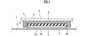
- FIG. 1 is a sectional view showing an embodiment of the sliding bearing of the present invention.
- FIG. 2 is an exploded view showing the slip bearing according to the present embodiment.
- a sliding bearing 1 according to an embodiment of the present invention includes a square fixing member 2 made of metal, a disk-shaped elastic member 3 made of chloroprene plate rubber or the like, and a metal circular member. It has a plate-shaped piston plate 4 and a sliding member 5. The other surface (the lower surface in the figure) of the sliding member 5 is in contact with a stainless steel floor 6 as the other structure in the present embodiment.
- a disc-shaped concave portion 2a is formed on the other surface (lower surface in the drawing) of fixing member 2 so as to extend from the other surface toward one surface (the upper surface in the drawing).
- One surface (the upper surface in the figure) of the elastic member 3 is adhered to the bottom surface of the concave portion 2a with a double-sided tape or an adhesive.
- One surface of the piston plate 4 (the surface on the side of the frame 8 (see FIG. 1 as one structure; the upper surface in the figure) is the other surface of the elastic member 3 (the floor 6 as the other structure (see FIG. 1)). 1), and is adhered to the lower surface of the figure with a double-sided tape or an adhesive.
- an annular groove 4a is provided at a position at a predetermined distance from one surface (the surface on the side of the skeleton 8 (see FIG. 1) as one structure; the upper surface of the drawing). ing.
- the predetermined interval is appropriately set according to the thickness and diameter of the slide bearing 1, the thickness and diameter of the elastic member 3, the type of the floor 6 and the frame 8, and the like.
- the width of the synthetic resin member 7 is set to be wider than the depth of the annular groove 4a, and when the synthetic resin member 7 is fitted into the annular groove 4a, the outer edge portion of the synthetic resin member 7 has an annular groove. 4a protrudes radially outward.
- the synthetic resin member 7 is formed of a synthetic resin having lower rigidity than the piston plate 4.
- a disc-shaped recess 4b for receiving the upper part of the sliding member 5 is provided on the other surface of the piston plate 4 (the surface on the floor 6 (see FIG. 1) side as the other structure; the lower surface in the figure). Is formed.
- the sliding member 5 is bonded to the bottom surface of the concave portion 4b with a double-sided tape or an adhesive.
- fixing member 2 is fixed to frame 8 as one structure in the present embodiment by inserting a bolt (not shown) into through hole 2 b or the like.
- the ratio of the diameter of the elastic member 3 divided by the thickness is preferably about 19 to 21.
- the skeleton 8 is arranged so as to face the floor 6, and the slide bearing 1 is arranged between the skeleton 8 and the floor 6.
- the piston plate 4 and the fixing member 2 come into contact with each other via the synthetic resin member 7 without the piston plate 4 and the fixing member 2 coming into direct contact with each other.
- the synthetic resin member 7 is fitted in an annular groove 4 a provided at a predetermined distance from one surface of the piston plate 4. For this reason, even when the piston plate 4 moves relatively to incline with respect to the fixing member 2, the portion of the side surface of the piston plate 4 on the floor 6 side as the other structure contacts the fixing member 2. This makes it difficult to damage the protective film such as the rust-proof film of the piston plate 4 and the fixing member 2.
- the shape of the synthetic resin member 7 is annular. This allows the synthetic resin member 7 to maintain the fitted state with the annular groove 4a without bonding the synthetic resin member 7 to the annular groove 4a. Therefore, the synthetic resin member 7 can be easily fitted into the annular groove.
- the synthetic resin member 7 is fitted in the annular groove 4a.
- the synthetic resin member 7 comes in contact with the elastic member 3 and sticks to the elastic member 3 as compared with a case where the elastic member 3 is fitted to the step portion of the piston plate as in the conventional product. Even if the synthetic resin member 7 is pulled in the direction away from the piston plate 4 by the restoring force, the synthetic resin member 7 is firmly fitted into the annular groove 4a, so that the synthetic resin member 7 is fitted to the step portion of the conventional product.
- the member 7 made of synthetic resin can be made harder to fall off from the piston plate 4.
- the shape of the synthetic resin member 7 is a C-shaped ring.
- the synthetic resin member of the present invention is not limited to a ring.
- the shape of the synthetic resin member may be an arc shape, and a plurality of synthetic resin members may be fitted into the annular groove and bonded.
- the skeleton 8 is described as one of the structures, and the floor 6 is described as the other structure, but the two structures of the present invention are not limited thereto.
- one structure may be a floor and the other structure may be a skeleton.
Landscapes
- Engineering & Computer Science (AREA)
- General Engineering & Computer Science (AREA)
- Architecture (AREA)
- Civil Engineering (AREA)
- Structural Engineering (AREA)
- Aviation & Aerospace Engineering (AREA)
- Acoustics & Sound (AREA)
- Physics & Mathematics (AREA)
- Mechanical Engineering (AREA)
- Vibration Prevention Devices (AREA)
- Buildings Adapted To Withstand Abnormal External Influences (AREA)
- Bridges Or Land Bridges (AREA)
- Business, Economics & Management (AREA)
- Emergency Management (AREA)
- Environmental & Geological Engineering (AREA)
Abstract
一方の構造体と一方の構造体に対向する他方の構造体との間に配置されるすべり支承であって、一方の構造体に固定される固定部材2と、固定部材2の他方の構造体側に設けられた凹部2aと、凹部2a内に配置され、凹部2aの底面に接着される弾性部材3と、弾性部材3の他方の構造体側に接着されたピストンプレート4と、ピストンプレート4の他方の構造体側に接着された滑り部材5と、ピストンプレート4の側面であって、一方の構造体側の面から所定の間隔を存して設けられた環状溝4aと、環状溝4aに嵌合する合成樹脂製部材7と、を備える。
Description
本発明は、2つの構造体の間に配置され、両構造体の相対的な回転や相対的な位置のずれを許容する、すべり支承に関する。
従来、一方の構造体と、一方の構造体に対向する他方の構造体との間に配置されるすべり支承であって、一方の構造体に固定される弾性部材と、弾性部材の他方の構造体側に接着されたピストンプレートと、ピストンプレートの他方の構造体側に接着された滑り部材と、を備えるすべり支承が知られている(例えば、日本国実開昭52-13612号公報参照)。
特許文献1のものでは、弾性部材により建物などの構造体の傾斜などを吸収できるが、地震などによる構造体の移動時に弾性部材が水平方向に変形する場合がある。弾性部材が水平方向に大きく変形すると弾性部材とピストンプレートとの接着が剥がれる虞があり、弾性部材とピストンプレートとの接着強度が問題となってくる。そこで、弾性部材の水平方向の変形量を規制すべく、一方の構造体と弾性部材との間に、凹部を有する断面コ字状の固定部材を固定し、固定部材の凹部内に弾性部材を収容することで、弾性部材の水平方向の変形量を凹部の側面で規制することが考えられる。しかしながら、この場合、弾性部材が変形すると、凹部側面にピストンプレートが接触する虞があり、固定部材やピストンプレートの防錆膜などの保護膜が損傷する虞がある。
本発明は、以上の点に鑑み、ピストンプレートや固定部材の保護膜の損傷を抑制することができるすべり支承を提供することを目的とする。
[1]上記目的を達成するため、本発明のすべり支承(例えば、実施形態のすべり支承1)は、
一方の構造体(例えば、実施形態の躯体8又は床6。以下、同一。)と前記一方の構造体に対向する他方の構造体(例えば、実施形態の床6又は躯体8。以下、同一。)との間に配置されるすべり支承であって、
前記一方の構造体に固定される固定部材(例えば、実施形態の固定部材2。以下、同一。)と、
前記固定部材の他方の構造体側に設けられた凹部(例えば、実施形態の凹部2a。以下、同一。)と、
前記凹部内に配置され、前記凹部の底面に接着される弾性部材(例えば、実施形態の弾性部材3。以下、同一。)と、
前記弾性部材の他方の構造体側に接着されたピストンプレート(例えば、実施形態のピストンプレート4。以下、同一。)と、
前記ピストンプレートの他方の構造体側に接着された滑り部材(例えば、実施形態の滑り部材5。以下、同一。)と、
前記ピストンプレートの側面であって、一方の構造体側の面から所定の間隔を存して設けられた環状溝(例えば、実施形態の環状溝4a。以下、同一。)と、
前記環状溝に嵌合する合成樹脂製部材(例えば、実施形態の合成樹脂製部材7。以下、同一。)と、
を備え、
前記合成樹脂製部材は、前記環状溝から径方向外側に突出していることを特徴とする。
一方の構造体(例えば、実施形態の躯体8又は床6。以下、同一。)と前記一方の構造体に対向する他方の構造体(例えば、実施形態の床6又は躯体8。以下、同一。)との間に配置されるすべり支承であって、
前記一方の構造体に固定される固定部材(例えば、実施形態の固定部材2。以下、同一。)と、
前記固定部材の他方の構造体側に設けられた凹部(例えば、実施形態の凹部2a。以下、同一。)と、
前記凹部内に配置され、前記凹部の底面に接着される弾性部材(例えば、実施形態の弾性部材3。以下、同一。)と、
前記弾性部材の他方の構造体側に接着されたピストンプレート(例えば、実施形態のピストンプレート4。以下、同一。)と、
前記ピストンプレートの他方の構造体側に接着された滑り部材(例えば、実施形態の滑り部材5。以下、同一。)と、
前記ピストンプレートの側面であって、一方の構造体側の面から所定の間隔を存して設けられた環状溝(例えば、実施形態の環状溝4a。以下、同一。)と、
前記環状溝に嵌合する合成樹脂製部材(例えば、実施形態の合成樹脂製部材7。以下、同一。)と、
を備え、
前記合成樹脂製部材は、前記環状溝から径方向外側に突出していることを特徴とする。
本発明によれば、ピストンプレートと固定部材とが直接接触することなく、ピストンプレートと固定部材とは合成樹脂製部材を介して接触することとなる。また、合成樹脂製部材は、ピストンプレートの一方の構造体側の面から所定の間隔を存して設けられた環状溝に嵌合されている。このため、ピストンプレートが固定部材に対して傾くように相対的に動いた場合であっても、ピストンプレートの側面の他方の構造体側の部分が固定部材に接触し難くなり、ピストンプレートや固定部材の防錆膜などの保護膜の損傷を抑制させることができる。
[2]また、本発明においては、前記合成樹脂製部材の形状は環状であることが好ましい。かかる構成によれば、合成樹脂製部材を環状溝に接着しなくても合成樹脂製部材が環状溝との嵌合状態を維持することができる。このため、合成樹脂製部材を容易に環状溝に嵌合させることができる。
図1を参照して、本発明の実施形態のすべり支承1は、金属製で正方形板状の固定部材2と、クロロプレンの板ゴムなどからなる円板形状の弾性部材3と、金属製で円板形状のピストンプレート4と、滑り部材5と、を備える。滑り部材5の他方の面(図の下面)は、本実施形態における他方の構造体としてのステンレス製の床6に接触している。
図2を参照して、固定部材2の他方の面(図の下面)には、他方の面から一方の面(図の上面)に向かってへこむ円板形状の凹部2aが形成されている。弾性部材3の一方の面(図の上面)は凹部2aの底面に、両面テープまたは接着剤で接着されている。
また、固定部材2の四隅には、一方の面(図の上面)から他方の面(図の下面)に向かって貫通する貫通孔2bが夫々設けられている。固定部材2とピストンプレート4には、防錆膜で覆うべく、カチオン電着塗装や溶融亜鉛めっきなどが施されている。なお、ピストンプレート4は必ずしも金属製でなくてもよく、例えば、合成樹脂製であってもよい。
ピストンプレート4の一方の面(一方の構造体としての躯体8(図1参照)側の面。図の上面。)は、弾性部材3の他方の面(他方の構造体としての床6(図1参照)側の面。図の下面。)に、両面テープまたは接着剤で接着されている。ピストンプレート4の周面には、一方の面(一方の構造体としての躯体8(図1参照)側の面。図の上面。)から所定の間隔を存した位置に環状溝4aが設けられている。
所定の間隔は、すべり支承1の厚さや直径、弾性部材3の厚さや直径、床6や躯体8の種類などに応じて適宜設定される。環状溝4aには、一箇所が切断されて端部7a同士が向き合うように環状に形成されたC字形状の合成樹脂製部材7が嵌合されている。合成樹脂製部材7の幅は、環状溝4aの深さよりも広く設定されており、合成樹脂製部材7を環状溝4aに嵌合させたときに、合成樹脂製部材7の外縁部分が環状溝4aから径方向外側に突出している。なお、合成樹脂製部材7は、ピストンプレート4を合成樹脂で形成する場合には、ピストンプレート4よりも剛性の低い合成樹脂で形成する。
また、ピストンプレート4の他方の面(他方の構造体としての床6(図1参照)側の面。図の下面。)には、滑り部材5の上方部分を受け入れる円板状の凹部4bが形成されている。滑り部材5は凹部4bの底面に両面テープまたは接着剤にて接着されている。
図1を参照して、固定部材2は、本実施形態における一方の構造体としての躯体8にボルト(図示省略)を貫通孔2bに挿通させるなどして固定されている。例えば、弾性部材3は、直径を厚さで除した割合が19~21程度とすることが良い。躯体8は床6に対向して配置されており、躯体8と床6との間にすべり支承1が配置されている。
本実施形態のすべり支承1によれば、ピストンプレート4と固定部材2とが直接接触することなく、ピストンプレート4と固定部材2とは合成樹脂製部材7を介して接触することとなる。また、合成樹脂製部材7は、ピストンプレート4の一方の面から所定の間隔を存して設けられた環状溝4aに嵌合されている。このため、ピストンプレート4が固定部材2に対して傾くように相対的に動いた場合であっても、ピストンプレート4の側面の他方の構造体としての床6側の部分が固定部材2に接触し難くなり、ピストンプレート4や固定部材2の防錆膜などの保護膜の損傷を抑制させることができる。
また、本実施形態においては、合成樹脂製部材7の形状は環状としている。これにより、合成樹脂製部材7を環状溝4aに接着しなくても合成樹脂製部材7が環状溝4aとの嵌合状態を維持することができる。このため、合成樹脂製部材7を容易に環状溝に嵌合させることができる。
また、本実施形態においては、合成樹脂製部材7は環状溝4aに嵌合されている。このため、従来品のように、ピストンプレートの段差部分に嵌められている場合と比較して、合成樹脂製部材7が弾性部材3と接触して弾性部材3に張り付き、その後、弾性部材3の復元力によって合成樹脂製部材7がピストンプレート4から離隔する方向に引張られたとしても、合成樹脂製部材7は環状溝4aにしっかりと嵌合されるため、従来品の段差部分に嵌合させる場合と比較して、合成樹脂製部材7をピストンプレート4から脱落し難くすることができる。
なお、本実施形態においては、合成樹脂製部材7の形状をC字形状の環状としている。しかしながら、本発明の合成樹脂製部材は環状に限らない。例えば、合成樹脂製部材の形状を円弧形状として、複数の合成樹脂製部材を環状溝に嵌合させて接着してもよい。
また、本実施形態においては、一方の構造体として躯体8、他方の構造体として床6を説明したが、本発明の両構造体はこれに限らない。例えば、一方の構造体を床とし、他方の構造体を躯体としてもよい。
1 すべり支承
2 固定部材
2a 凹部
3 弾性部材
4 ピストンプレート
4a 環状溝
4b 凹部
5 滑り部材
6 床(他方の構造体)
7 合成樹脂製部材
8 躯体(一方の構造体)
2 固定部材
2a 凹部
3 弾性部材
4 ピストンプレート
4a 環状溝
4b 凹部
5 滑り部材
6 床(他方の構造体)
7 合成樹脂製部材
8 躯体(一方の構造体)
Claims (2)
- 一方の構造体と前記一方の構造体に対向する他方の構造体との間に配置されるすべり支承であって、
前記一方の構造体に固定される固定部材と、
前記固定部材の他方の構造体側に設けられた凹部と、
前記凹部内に配置され、前記凹部の底面に接着される弾性部材と、
前記弾性部材の他方の構造体側に接着されたピストンプレートと、
前記ピストンプレートの他方の構造体側に接着された滑り部材と、
前記ピストンプレートの側面であって、一方の構造体側の面から所定の間隔を存して設けられた環状溝と、
前記環状溝に嵌合する合成樹脂製部材と、を備え、
前記合成樹脂製部材は、前記環状溝から径方向外側に突出していることを特徴とするすべり支承。 - 請求項1に記載のすべり支承であって、
前記合成樹脂製部材の形状は環状であることを特徴とするすべり支承。
Priority Applications (1)
| Application Number | Priority Date | Filing Date | Title |
|---|---|---|---|
| KR1020207029388A KR102454457B1 (ko) | 2018-08-09 | 2019-07-10 | 미끄럼 베어링 |
Applications Claiming Priority (2)
| Application Number | Priority Date | Filing Date | Title |
|---|---|---|---|
| JP2018-150528 | 2018-08-09 | ||
| JP2018150528A JP7092607B2 (ja) | 2018-08-09 | 2018-08-09 | すべり支承 |
Publications (1)
| Publication Number | Publication Date |
|---|---|
| WO2020031604A1 true WO2020031604A1 (ja) | 2020-02-13 |
Family
ID=69415559
Family Applications (1)
| Application Number | Title | Priority Date | Filing Date |
|---|---|---|---|
| PCT/JP2019/027374 Ceased WO2020031604A1 (ja) | 2018-08-09 | 2019-07-10 | すべり支承 |
Country Status (4)
| Country | Link |
|---|---|
| JP (1) | JP7092607B2 (ja) |
| KR (1) | KR102454457B1 (ja) |
| TW (1) | TWI701393B (ja) |
| WO (1) | WO2020031604A1 (ja) |
Citations (2)
| Publication number | Priority date | Publication date | Assignee | Title |
|---|---|---|---|---|
| JPH10246287A (ja) * | 1997-03-07 | 1998-09-14 | Fujitsu Ltd | 台足構造 |
| JP2005256862A (ja) * | 2004-03-09 | 2005-09-22 | Nippon Pillar Packing Co Ltd | 免震支承具 |
Family Cites Families (5)
| Publication number | Priority date | Publication date | Assignee | Title |
|---|---|---|---|---|
| JPS5213612A (en) | 1975-07-22 | 1977-02-02 | Nippon Denso Co Ltd | Generator |
| JPH11336202A (ja) * | 1998-05-26 | 1999-12-07 | Nippon Pillar Packing Co Ltd | 免震支承装置 |
| JP2001241502A (ja) | 2000-02-25 | 2001-09-07 | Kawaguchi Metal Industries Co Ltd | 免震滑り支承 |
| JP2003301883A (ja) | 2002-04-12 | 2003-10-24 | Kawaguchi Metal Industries Co Ltd | 滑り支承 |
| JP6143588B2 (ja) | 2013-07-11 | 2017-06-07 | オイレス工業株式会社 | 積層すべり部材及びこの積層すべり部材を使用したすべり支承 |
-
2018
- 2018-08-09 JP JP2018150528A patent/JP7092607B2/ja active Active
-
2019
- 2019-07-10 KR KR1020207029388A patent/KR102454457B1/ko active Active
- 2019-07-10 WO PCT/JP2019/027374 patent/WO2020031604A1/ja not_active Ceased
- 2019-07-18 TW TW108125424A patent/TWI701393B/zh active
Patent Citations (2)
| Publication number | Priority date | Publication date | Assignee | Title |
|---|---|---|---|---|
| JPH10246287A (ja) * | 1997-03-07 | 1998-09-14 | Fujitsu Ltd | 台足構造 |
| JP2005256862A (ja) * | 2004-03-09 | 2005-09-22 | Nippon Pillar Packing Co Ltd | 免震支承具 |
Also Published As
| Publication number | Publication date |
|---|---|
| JP7092607B2 (ja) | 2022-06-28 |
| TW202009390A (zh) | 2020-03-01 |
| KR20200128143A (ko) | 2020-11-11 |
| JP2020026813A (ja) | 2020-02-20 |
| TWI701393B (zh) | 2020-08-11 |
| KR102454457B1 (ko) | 2022-10-14 |
Similar Documents
| Publication | Publication Date | Title |
|---|---|---|
| KR101065878B1 (ko) | 자기중심맞춤 슬라이딩 베어링 | |
| EP2562439B1 (en) | Seismic isolation device | |
| JP2014141271A (ja) | ローラー | |
| JP6762900B2 (ja) | ディスクブレーキ用積層シム | |
| WO2020031604A1 (ja) | すべり支承 | |
| US20120031026A1 (en) | Raised floor with improved structure | |
| MA50020B1 (fr) | Substrat métallique revêtu | |
| JP7449822B2 (ja) | 支承装置 | |
| CN113748284B (zh) | 垫圈 | |
| JP3162840U (ja) | 免震装置 | |
| JP2003301883A (ja) | 滑り支承 | |
| JP2017122351A (ja) | 床の施工方法および床構造体 | |
| KR101538956B1 (ko) | 이탈 방지형 교량 디스크받침 | |
| JP2022074216A (ja) | すべり材ユニット及びすべり支承 | |
| EP3971428B1 (en) | Fixing washer | |
| JP5555673B2 (ja) | マット及び該マットを用いたタイルマット | |
| JPH11336201A (ja) | 支承装置 | |
| US20170326911A1 (en) | Aircraft wheel | |
| JPH11303933A (ja) | 滑り支承構造 | |
| JP2017075615A (ja) | すべり支承装置 | |
| JP3135378U (ja) | 座金 | |
| JP2001220826A (ja) | 免震用滑り支承 | |
| JP2021032388A (ja) | すべり支承 | |
| JP3282801B2 (ja) | 免震用滑り支承 | |
| JP4174456B2 (ja) | 滑り支承 |
Legal Events
| Date | Code | Title | Description |
|---|---|---|---|
| 121 | Ep: the epo has been informed by wipo that ep was designated in this application |
Ref document number: 19848523 Country of ref document: EP Kind code of ref document: A1 |
|
| ENP | Entry into the national phase |
Ref document number: 20207029388 Country of ref document: KR Kind code of ref document: A |
|
| NENP | Non-entry into the national phase |
Ref country code: DE |
|
| 122 | Ep: pct application non-entry in european phase |
Ref document number: 19848523 Country of ref document: EP Kind code of ref document: A1 |