WO2020031436A1 - 脳性ナトリウム利尿ペプチドの測定方法および脳性ナトリウム利尿ペプチドの測定キット - Google Patents
脳性ナトリウム利尿ペプチドの測定方法および脳性ナトリウム利尿ペプチドの測定キット Download PDFInfo
- Publication number
- WO2020031436A1 WO2020031436A1 PCT/JP2019/016737 JP2019016737W WO2020031436A1 WO 2020031436 A1 WO2020031436 A1 WO 2020031436A1 JP 2019016737 W JP2019016737 W JP 2019016737W WO 2020031436 A1 WO2020031436 A1 WO 2020031436A1
- Authority
- WO
- WIPO (PCT)
- Prior art keywords
- natriuretic peptide
- brain natriuretic
- metal film
- bnp
- protease inhibitor
- Prior art date
Links
Images


Classifications
-
- G—PHYSICS
- G01—MEASURING; TESTING
- G01N—INVESTIGATING OR ANALYSING MATERIALS BY DETERMINING THEIR CHEMICAL OR PHYSICAL PROPERTIES
- G01N33/00—Investigating or analysing materials by specific methods not covered by groups G01N1/00 - G01N31/00
- G01N33/48—Biological material, e.g. blood, urine; Haemocytometers
- G01N33/50—Chemical analysis of biological material, e.g. blood, urine; Testing involving biospecific ligand binding methods; Immunological testing
- G01N33/58—Chemical analysis of biological material, e.g. blood, urine; Testing involving biospecific ligand binding methods; Immunological testing involving labelled substances
- G01N33/582—Chemical analysis of biological material, e.g. blood, urine; Testing involving biospecific ligand binding methods; Immunological testing involving labelled substances with fluorescent label
-
- G—PHYSICS
- G01—MEASURING; TESTING
- G01N—INVESTIGATING OR ANALYSING MATERIALS BY DETERMINING THEIR CHEMICAL OR PHYSICAL PROPERTIES
- G01N33/00—Investigating or analysing materials by specific methods not covered by groups G01N1/00 - G01N31/00
- G01N33/48—Biological material, e.g. blood, urine; Haemocytometers
- G01N33/50—Chemical analysis of biological material, e.g. blood, urine; Testing involving biospecific ligand binding methods; Immunological testing
- G01N33/53—Immunoassay; Biospecific binding assay; Materials therefor
- G01N33/543—Immunoassay; Biospecific binding assay; Materials therefor with an insoluble carrier for immobilising immunochemicals
- G01N33/54366—Apparatus specially adapted for solid-phase testing
- G01N33/54373—Apparatus specially adapted for solid-phase testing involving physiochemical end-point determination, e.g. wave-guides, FETS, gratings
-
- G—PHYSICS
- G01—MEASURING; TESTING
- G01N—INVESTIGATING OR ANALYSING MATERIALS BY DETERMINING THEIR CHEMICAL OR PHYSICAL PROPERTIES
- G01N21/00—Investigating or analysing materials by the use of optical means, i.e. using sub-millimetre waves, infrared, visible or ultraviolet light
- G01N21/62—Systems in which the material investigated is excited whereby it emits light or causes a change in wavelength of the incident light
- G01N21/63—Systems in which the material investigated is excited whereby it emits light or causes a change in wavelength of the incident light optically excited
- G01N21/64—Fluorescence; Phosphorescence
- G01N21/645—Specially adapted constructive features of fluorimeters
- G01N21/648—Specially adapted constructive features of fluorimeters using evanescent coupling or surface plasmon coupling for the excitation of fluorescence
-
- G—PHYSICS
- G01—MEASURING; TESTING
- G01N—INVESTIGATING OR ANALYSING MATERIALS BY DETERMINING THEIR CHEMICAL OR PHYSICAL PROPERTIES
- G01N2333/00—Assays involving biological materials from specific organisms or of a specific nature
- G01N2333/435—Assays involving biological materials from specific organisms or of a specific nature from animals; from humans
- G01N2333/575—Hormones
- G01N2333/58—Atrial natriuretic factor complex; Atriopeptin; Atrial natriuretic peptide [ANP]; Brain natriuretic peptide [BNP, proBNP]; Cardionatrin; Cardiodilatin
Definitions
- the present invention relates to a method for measuring brain natriuretic peptide and a kit for measuring brain natriuretic peptide.
- BNP Brain natriuretic peptide
- Patent Document 1 discloses a method for measuring the concentration of BNP using a sandwich immunoassay using magnetic particles as a solid phase.
- An object of the present invention is to provide a BNP measurement method and a BNP measurement kit that can measure the concentration of BNP in a sample with higher sensitivity and higher reproducibility than conventional measurement methods.
- a measurement chip including a metal film and a binding substance immobilized on the metal film and specifically binding to the brain natriuretic peptide is prepared.
- a kit for measuring brain natriuretic peptide includes a metal membrane, a measurement chip immobilized on the metal membrane, and a binding substance that binds to brain natriuretic peptide, and a serine protease inhibitor. And a pretreatment agent containing one or more protease inhibitors selected from the group consisting of cysteine protease inhibitors, and a labeling reagent for labeling brain natriuretic peptide with a fluorescent substance.
- the BNP concentration in a sample can be measured with higher sensitivity and higher reproducibility than the conventional measurement method.
- FIG. 1 is a flowchart showing an example of the method for measuring cerebral diuretic peptide according to the present embodiment.
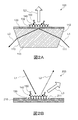
- FIG. 2A is a schematic cross-sectional view for explaining the configuration of a measurement chip for PC-SPFS
- FIG. 2B is a schematic cross-sectional view for explaining the configuration of a measurement chip for GC-SPFS.
- FIG. 3 is a schematic cross-sectional view showing an example of a measurement chip for PC-SPFS.
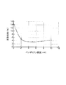
- FIG. 4 is a graph showing the relationship between aprotinin concentration and measurement reproducibility (coefficient of variation) when aprotinin is used as a protease inhibitor.
- FIG. 5 is a graph showing the relationship between benzamidine concentration and measurement reproducibility (coefficient of variation) when benzamidine is used as a protease inhibitor.
- BNP brain natriuretic peptide
- SPFS Surface Plasmon-field enhanced Fluorescence Spectroscopy
- SPR surface plasmon resonance
- the amount of a specimen (for example, blood or a diluent thereof) may be small.
- a mechanical stimulus to the specimen on the reaction field in order to ensure that a small amount of BNP in the specimen is captured by a BNP-binding substance (for example, an anti-BNP antibody) immobilized on the reaction field.
- a BNP-binding substance for example, an anti-BNP antibody
- the present inventors have conducted intensive studies based on the above idea, and as a result, by adding a protease inhibitor to the sample at the pretreatment stage of the measurement, the BNP can be measured with high sensitivity and high reproducibility by SPFS. They have found that it is possible and completed the method for measuring BNP according to the present embodiment.
- FIG. 1 is a flowchart illustrating an example of the BNP measurement method according to the present embodiment.
- Step S10 a measurement chip including a metal film and a binding substance that specifically binds to BNP is prepared (Step S10).
- SPFS an evanescent wave generated when a metal film is irradiated with light (in this embodiment, excitation light) and surface plasmons are combined to generate SPR.
- a method for generating the SPR a method of disposing a prism on one surface of a metal film (Kretschmann arrangement), a method of forming a diffraction grating on the metal film, and the like are known.
- An SPFS employing the former method is referred to as prism coupling (PC) -SPFS, and an SPFS employing the latter method is referred to as grating coupling (GC) -SPFS.
- the method of measuring BNP according to the present embodiment may employ either PC-SPFS or GC-SPFS.
- the metal film causes SPR when irradiated with excitation light.
- the kind of the metal constituting the metal film is not particularly limited as long as the metal can cause SPR.
- Examples of the metal constituting the metal film include gold, silver, copper, aluminum and alloys thereof.
- the binding substance can specifically bind to BNP, and is immobilized on a metal film to capture BNP in the sample. Usually, the binding substance is uniformly immobilized in a predetermined region (reaction field) on the metal film.
- the type of the binding substance immobilized on the metal film is not particularly limited as long as it can specifically bind to BNP. Examples of the binding substance include an antibody capable of specifically binding to BNP (anti-BNP antibody), a nucleic acid capable of specifically binding to BNP, a lipid capable of specifically binding to BNP, and an antibody other than an antibody capable of specifically binding to BNP. Proteins.
- the anti-BNP antibody may be a monoclonal antibody, a polyclonal antibody, or a fragment of the antibody.
- the kind of the binding substance immobilized on the metal film may be one kind or two or more kinds.
- the anti-BNP antibody immobilized on the metal film is one or more anti-BNP monoclonal antibodies or anti-BNP polyclonal antibodies.
- the method for immobilizing the binding substance is not particularly limited.
- a self-assembled monolayer hereinafter, referred to as “SAM”) or a polymer film to which a binding substance (for example, an anti-BNP antibody) is bound may be formed on a metal film.
- SAMs include films formed with substituted aliphatic thiols, such as HOOC- (CH 2 ) 11 -SH.
- the material constituting the polymer film include polyethylene glycol and MPC polymer.
- a polymer having a reactive group (or a functional group convertible into a reactive group) capable of binding to a binding substance (for example, an anti-BNP antibody) is immobilized on a metal film, and the binding substance (for example, an anti-BNP antibody) is attached to the polymer.
- a binding substance for example, an anti-BNP antibody
- the measuring chip is preferably a structure with each piece having a length of several mm to several cm, but may be a smaller structure or a larger structure which is not included in the category of “chip”.
- FIG. 2A is a schematic cross-sectional view for explaining the configuration of a measurement chip for PC-SPFS
- FIG. 2B is a schematic cross-sectional view for explaining the configuration of a measurement chip for GC-SPFS.
- the size and shape of each component are not accurate for convenience of explanation.
- These figures show examples in which an anti-BNP antibody is used as a binding substance.
- the measurement chip 100 for PC-SPFS has a prism 110, a metal film 120, and (a layer of) the anti-BNP antibody 130.
- the prism 110 is made of a dielectric material transparent to the excitation light L1, and has an incident surface 111 on which the excitation light L1 is incident, a film forming surface 112 on which the excitation light L1 is reflected, and an emission surface 113 on which the reflected light L2 is emitted. Having.
- the shape of the prism 110 is not particularly limited. In the example shown in FIG. 2A, the shape of the prism 110 is a column having a trapezoidal bottom surface.
- the surface corresponding to one bottom side of the trapezoid is the film forming surface 112, the surface corresponding to one leg is the incident surface 111, and the surface corresponding to the other leg is the emission surface 113.
- the material of the prism 110 include resin and glass.
- the material of the prism 110 is preferably a resin having a refractive index of 1.4 to 1.6 with respect to the excitation light and a small birefringence.
- the metal film 120 is disposed on the deposition surface 112 of the prism 110.
- the method for forming the metal film 120 is not particularly limited. Examples of the method for forming the metal film 120 include sputtering, vapor deposition, and plating.
- the thickness of the metal film 120 is not particularly limited, but is preferably in the range of 30 to 70 nm.
- the measurement chip 200 for GC-SPFS has a metal film 210 on which a diffraction grating 211 is formed and (a layer of) the anti-BNP antibody 130.
- the method for forming the metal film 210 is not particularly limited. Examples of the method for forming the metal film 210 include sputtering, vapor deposition, and plating.
- the thickness of the metal film 210 is not particularly limited, but is preferably in the range of 30 to 500 nm.
- the shape of the diffraction grating 211 is not particularly limited as long as an evanescent wave can be generated.
- the diffraction grating 211 may be a one-dimensional diffraction grating or a two-dimensional diffraction grating.
- the one-dimensional diffraction grating a plurality of parallel ridges are formed on the surface of the metal film 210 at predetermined intervals.
- convex portions having a predetermined shape are periodically arranged on the surface of the metal film 210. Examples of the arrangement of the convex portions include a square lattice, a triangular (hexagonal) lattice, and the like.
- Examples of the cross-sectional shape of the diffraction grating 211 include a rectangular wave shape, a sine wave shape, a sawtooth shape, and the like.
- the method for forming the diffraction grating 211 is not particularly limited. For example, after the metal film 210 is formed on a flat substrate (not shown), the metal film 210 may be provided with an uneven shape. Further, the metal film 210 may be formed on a substrate (not shown) provided with a concavo-convex shape in advance. In any case, the metal film 210 including the diffraction grating 211 can be formed.
- the metal film 210 (diffraction grating 211) is irradiated with the excitation light L1 so that SPR occurs in the metal film 210 (diffraction grating 211)
- the electric field enhanced by the SPR causes the metal film 210 (diffraction). It occurs near the grating 211).
- the fluorescent substance 150 is excited by the enhanced electric field and emits the fluorescent light L3.
- FIG. 3 is a schematic cross-sectional view showing an example of a measurement chip for PC-SPFS.
- the measurement chip 300 includes a prism 110 having an entrance surface 111, a deposition surface 112, and an emission surface 113, a metal film 120 formed on the deposition surface 112 of the prism 110, And a channel cover 310 disposed on the film formation surface 112 or the metal film 120.
- the entrance plane 111 and the exit plane 113 are present before and behind the plane of the paper, respectively.
- the measurement chip 300 further has a flow channel 320, a liquid injection part 330 connected to one end of the flow channel 320, and a storage part 340 connected to the other end of the flow channel 320.
- the channel lid 310 is bonded to the metal film 120 (or the prism 110) via an adhesive layer 350 such as a double-sided tape, and the adhesive layer 350 plays a role in defining the side surface shape of the channel 320. I also carry.
- the anti-BNP antibody 130 is immobilized in a part of the metal film 120 (reaction field) exposed in the flow channel 320.
- the liquid injection section 330 is closed by the liquid injection section covering film 331, and the storage section 340 is closed by the storage section covering film 341.
- the storage portion covering film 341 is provided with a vent hole 342.
- the channel lid 310 is formed of a material transparent to the fluorescent light L3. However, as long as it does not hinder the extraction of the fluorescent light L3, a part of the channel cover 310 may be formed of a material opaque to the fluorescent light L3. Examples of the material transparent to the fluorescent light L3 include a resin.
- the channel lid 310 may be bonded to the metal film 120 (or the prism 110) by laser welding, ultrasonic welding, pressure bonding using a clamp member, or the like without using the adhesive layer 350. In this case, the side surface shape of the channel 320 is defined by the channel lid 310.
- a pipette tip is inserted into the liquid injection section 330.
- the opening of the liquid injection part 330 (the through-hole provided in the liquid injection part covering film 331) is in contact with the outer periphery of the pipette tip without any gap. Therefore, the liquid can be introduced into the flow channel 320 by injecting the liquid from the pipette tip into the liquid injection portion 330, and the liquid in the flow channel 320 can be introduced by suctioning the liquid in the liquid injection portion 330 into the pipette tip. Liquid can be removed. Further, by alternately injecting and sucking the liquid, the liquid can be reciprocated in the flow channel 320.
- a pretreatment sample is obtained by adding a protease inhibitor to a sample that may contain BNP (step S20).
- the type of specimen is not particularly limited.
- specimens include blood, serum, plasma and diluents thereof.
- whole blood can also be used as a specimen.
- the addition of protease to a sample is performed by adding a pretreatment agent containing a protease inhibitor to the sample.
- the pretreatment agent may be a protease inhibitor alone or may be a composition containing a protease inhibitor.
- the pretreatment agent is a liquid containing a protease.
- the liquid containing the protease inhibitor can also serve as a diluent for the specimen.
- the timing of adding the protease inhibitor (pretreatment agent) to the sample is not particularly limited as long as it is performed at the beginning of the measurement, but the earlier the timing, the better.
- the protease inhibitor can be added to the sample at the same time as blood collection.
- the sample is diluted before the measurement, if a liquid containing a protease inhibitor is used as a diluent, the protease inhibitor can be added to the sample at the beginning of the measurement.
- protease inhibitor is not particularly limited as long as it can inhibit BNP degradation by erythrocyte-derived protease.
- protease inhibitors include serine protease inhibitors and cysteine protease inhibitors.
- serine protease inhibitors include benzamidine, aprotinin, TLCK (Tosyl-L-lysyl-chloromehethane @ hydrochloride), PMFS (Phenylmethylsulfonyl @ fluoride), and AEBSF (Aminozyl.
- cysteine proteases include aprotinin, PMFS, AEBSF.
- the final concentration of the protease inhibitor (the concentration in the pretreated sample) may be appropriately set according to the type of the protease inhibitor to be used.
- the concentration of benzamidine in the pretreated sample is preferably 1 mM or more, more preferably 1.5 mM or more, and more preferably 2 mM or more from the viewpoint of preventing BNP degradation. Is more preferable, and 3 mM is particularly preferable.
- the upper limit of the concentration of benzamidine in the pretreated sample is not particularly limited, but is, for example, 10 mM or less, 5 mM or less, and 3.5 mM or less.
- the concentration of aprotinin in the pretreated sample is preferably 1 ⁇ g / mL or more, more preferably 1.5 ⁇ g / mL or more, from the viewpoint of preventing BNP degradation. It is more preferably at least 2 ⁇ g / mL.
- the upper limit of the aprotinin concentration in the pretreated sample is not particularly limited, but is, for example, 50 ⁇ g / mL or less, 10 ⁇ g / mL or less, and 5 ⁇ g / mL.
- the TLCK concentration in the pretreated sample is preferably 0.1 mM or more, more preferably 0.4 mM or more, from the viewpoint of preventing BNP degradation.
- the upper limit of the TLCK concentration in the pretreated sample is not particularly limited, but is, for example, 1 mM or less.
- the concentration of PMFS in the pretreated sample is preferably 0.1 mM or more, more preferably 2 mM or more, from the viewpoint of preventing BNP degradation.
- the upper limit of the PMFS concentration in the pretreated sample is not particularly limited, but is, for example, 10 mM or less.
- the AEBSF concentration in the pretreated sample is preferably 0.4 mM or more, more preferably 2 mM or more, from the viewpoint of preventing BNP degradation.
- the upper limit of the AEBSF concentration in the pretreated sample is not particularly limited, but is, for example, 4 mM or less.
- a metal protease inhibitor may be further added to the sample in addition to the serine protease inhibitor or the cysteine protease inhibitor.
- a pretreatment agent containing a metalloprotease inhibitor may be added to the specimen.
- metalloprotease inhibitors include ethylenediaminetetraacetic acid, ethylenediaminetetraacetic acid, glycol etherdiaminetetraacetic acid, and glycoletherdiaminetetraacetic acid.
- concentration of the metal protease inhibitor in the pretreated sample is not particularly limited, but is preferably, for example, 1.5 mg / mL to 1.8 mg / mL.
- the pretreatment sample is provided on the metal film of the measurement chip, and BNP contained in the pretreatment sample is bound to the binding substance immobilized on the metal film (primary reaction; step S30).
- the method of providing the pre-processed sample is not particularly limited.
- the pretreatment sample may be provided on a metal film using a pipette having a pipette tip mounted on the tip.
- the surface of the metal film is washed with a buffer solution or the like to remove components not bound to the binding substance.
- a mechanical stimulus is applied to the pretreated sample to bind BNP to the binding substance.
- BNP degradation due to protease from erythrocytes is unlikely to occur, so that the reproducibility of the measurement results is high. Is not easily reduced.
- a labeling reagent is provided on the metal film of the measurement chip, and BNP bound to the binding substance is labeled with a fluorescent substance (secondary reaction; step S40).
- the method for providing the labeling reagent is not particularly limited.
- the labeling reagent may be provided on the metal film using a pipette having a pipette tip mounted on the tip.
- the surface of the metal film is washed with a buffer solution or the like to remove the fluorescent substance not labeling BNP.
- the type of labeling reagent is not particularly limited as long as BNP bound to the binding substance can be labeled with a fluorescent substance.
- the labeling reagent is a fluorescent-labeled binding substance that specifically binds to BNP.
- the type of the binding substance contained in the labeling reagent is not particularly limited as long as it can specifically bind to BNP.
- the binding substance include an antibody capable of specifically binding to BNP (anti-BNP antibody), a nucleic acid capable of specifically binding to BNP, a lipid capable of specifically binding to BNP, and an antibody other than an antibody capable of specifically binding to BNP. Proteins.
- the type of the binding substance contained in the labeling reagent may be the same as or different from the type of the binding substance immobilized on the metal film.
- the anti-BNP antibody may be a monoclonal antibody, a polyclonal antibody, or a fragment of the antibody.
- the type of the binding substance contained in the labeling reagent may be one type, or two or more types.
- the fluorescent-labeled anti-BNP antibody is one or more anti-BNP monoclonal antibodies or anti-BNP polyclonal antibodies. In this case, it is preferable that the anti-BNP monoclonal antibody and the anti-BNP polyclonal antibody labeled with a fluorescent substance are different from one or more kinds of anti-BNP monoclonal antibodies immobilized on the metal film.
- the type of fluorescent substance is not particularly limited as long as it can be used in SPFS.
- fluorescent materials include cyanine dyes, Alexa Fluor® dyes from Thermo Scientific, and CF dyes from Biotium. Alexa @ Fluor dyes and CF dyes have a high quantum efficiency with respect to the wavelength of excitation light used in SPFS among commercially available fluorescent dyes. Further, since the CF dye does not cause much fading at the time of fluorescence detection, fluorescence detection can be stably performed.
- the method for labeling the binding substance with a fluorescent substance is not particularly limited, and may be appropriately selected from known methods. For example, a fluorescent substance may be bound to an amino group or a sulfhydryl group of a binding substance (for example, an anti-BNP antibody).
- BNP was labeled with a fluorescent substance after binding BNP to the binding substance immobilized on the metal film.
- BNP was bound before binding BNP to the binding substance immobilized on the metal film. It may be labeled with a fluorescent substance.
- the sample or the pretreatment sample and the labeling reagent may be mixed before the pretreatment sample is provided on the metal film.
- the step of binding BNP to the binding substance immobilized on the metal film and the step of labeling BNP with a fluorescent substance may be performed simultaneously. In this case, the pretreatment sample and the labeling reagent may be provided simultaneously on the metal film.
- fluorescence indicating the amount of BNP is measured by SPFS (step S50). Specifically, in a state in which BNP labeled with a fluorescent substance is bound to a binding substance immobilized on the metal film, the metal film is irradiated with excitation light so that SPR occurs in the metal film, and thereby the fluorescent light is irradiated. The fluorescence emitted from the substance is measured. Usually, a signal value correlated with the amount of BNP is calculated by subtracting a previously measured optical blank value from a measured fluorescence value. If necessary, the signal value may be converted to the amount or concentration of BNP by using a previously prepared calibration curve or the like.
- the excitation light L 1 is applied to the metal film 120 via the prism 110.
- SPR occurs in the metal film 120
- the fluorescent substance 150 existing near the metal film 120 is excited by the enhanced electric field and emits the fluorescent light L3.
- the incident angle of the excitation light L1 with respect to the metal film 120 is set so that SPR occurs in the metal film 120, but is preferably a resonance angle or an enhancement angle.
- the “resonance angle” means an incident angle when the amount of the reflected light L2 is minimized when scanning the incident angle of the excitation light L1 with respect to the metal film 120.
- the “enhancement angle” refers to scattered light having the same wavelength as the excitation light L1 emitted above the metal film 120 (on the opposite side of the prism 110) when the incident angle of the excitation light L1 with respect to the metal film 120 is scanned. It means the angle of incidence when the amount of (plasmon scattered light) is at a maximum.
- the excitation light L1 is directly applied to the metal film 210 (diffraction grating 211).
- SPR occurs in the metal film 210 (diffraction grating 211), and the fluorescent substance 150 existing near the metal film 210 (diffraction grating 211) is excited by the enhanced electric field and emits the fluorescent light L3.
- the incident angle of the excitation light L1 with respect to the metal film 210 is set so that SPR occurs in the metal film 210, and an angle at which the intensity of the enhanced electric field formed by the SPR is the highest is preferable.
- the optimum incident angle of the excitation light L1 is appropriately set according to the pitch of the diffraction grating 211, the wavelength of the excitation light L1, the type of metal forming the metal film 210, and the like.
- the type of the excitation light is not particularly limited, but is usually a laser beam.
- the excitation light is a laser light emitted from a laser light source having an output of 15 to 30 mW.
- the wavelength of the excitation light is appropriately set according to the excitation wavelength of the fluorescent substance used.
- the fluorescence detector is installed in a direction in which the fluorescence intensity is highest with respect to the measurement chip.
- the direction in which the intensity of the fluorescent light L3 is highest is the normal direction of the metal film 120. It is installed directly above.
- the direction in which the intensity of the fluorescent light L3 is highest is a direction inclined to some extent with respect to the normal line of the metal film 120.
- the instrument is placed not directly above the measuring chip.
- the detector is, for example, a photomultiplier tube (PMT) or an avalanche photodiode (APD).
- the concentration of BNP contained in the sample can be measured.
- the BNP kit comprises a set of the measurement chip, a sample pretreatment agent containing the protease inhibitor (a serine protease inhibitor or a cysteine protease inhibitor), and the labeling reagent. It was done.
- a sample pretreatment agent containing the protease inhibitor (a serine protease inhibitor or a cysteine protease inhibitor)
- the labeling reagent By setting the measurement chip, the sample pretreatment agent, and the labeling reagent in advance as described above, a user (a medical worker or the like) can more easily perform the above-described BNP measurement method.
- BNP in a sample can be measured with high sensitivity and higher reproducibility using SPFS.
- a measurement chip 300 having the configuration shown in FIG. 3 was prepared.
- a mouse anti-BNP monoclonal antibody was immobilized on a specific region (reaction portion) of the metal film 120 (gold thin film) exposed in the flow channel 320.
- the first diluent is a MES buffer without protease inhibitors.
- the second diluent is a MES buffer containing a predetermined amount of aprotinin as a protease inhibitor.
- the third diluent is a MES buffer containing a predetermined amount of TLCK as a protease inhibitor.
- the fourth diluent is a MES buffer containing a predetermined amount of benzamidine as a protease inhibitor.
- the fifth diluent is a MES buffer containing a predetermined amount of EDTA as a protease inhibitor.
- the concentration of EDTA was 1.5 mg / mL in the first pretreatment sample prepared using the first diluent containing no protease inhibitor.
- the EDTA concentration was 1.5 mg / mL, and the aprotinin concentration was 1 ⁇ g / mL.
- the concentration of EDTA was 1.5 mg / mL, and the concentration of TLCK was 0.4 mM.
- the concentration of EDTA was 1.5 mg / mL, and the concentration of benzamidine was 2 mM.
- the EDTA concentration was 5.2 mg / mL.
- a pre-processed sample (any one of the first to fifth pre-processed samples) was introduced into the flow channel 320 from the liquid injection unit 330 by a pipette tip, and the liquid was reciprocated (primary reaction). After removing the pre-processed sample in the flow channel 320 from the liquid injection part 330, the flow channel 320 was washed once with a cleaning liquid. Then, a mouse anti-BNP monoclonal antibody labeled with a labeling reagent (CF dye (Biotium) via an amino group) was introduced into the flow channel 320 from the liquid injection part 330, and sent back and forth (secondary reaction).
- CF dye Biotium
- the inside of the flow channel 320 was washed three times with a cleaning liquid, and then the measurement liquid was introduced into the flow channel 320 from the liquid injection part 330.
- the fluorescence value was measured by SPFS, that is, the metal film 120 was irradiated with excitation light (laser light) from the prism 110 side so that the incident angle of the excitation light with respect to the metal film 120 became the enhancement angle, and emitted at that time.
- the previously measured optical blank value was subtracted from the obtained fluorescence value to calculate a signal value correlated with the amount of BNP, and the same measurement was performed six times for each pretreated sample.
- the coefficient of variation cv (%) of the six measurement results was calculated.
- the variation coefficient is 8% or less, it is evaluated that reproducibility is sufficiently high.
- Table 1 shows the coefficient of variation of the results of six measurements for each pretreated sample.
- EDTA metal protease inhibitor
- aprotinin serine protease inhibitor
- TLCK serine protease inhibitor
- benzamidine serine protease inhibitor, cysteine protease inhibitor
- FIGS. 4 and 5 show that when the concentration of aprotinin is 1 ⁇ g / mL or more, the reproducibility of the measurement results is improved.
- FIG. 5 shows that when the concentration of benzamidine is 1 mM or more, the reproducibility of the measurement results is improved.
- ⁇ ⁇ BNP can be measured with high sensitivity and high reproducibility by using the BNP measurement method or the measurement kit according to the present embodiment. Therefore, the BNP detection method and measurement kit according to the present invention are useful for, for example, clinical tests.
Landscapes
- Health & Medical Sciences (AREA)
- Life Sciences & Earth Sciences (AREA)
- Engineering & Computer Science (AREA)
- Immunology (AREA)
- Molecular Biology (AREA)
- Biomedical Technology (AREA)
- Chemical & Material Sciences (AREA)
- Hematology (AREA)
- Urology & Nephrology (AREA)
- Cell Biology (AREA)
- Microbiology (AREA)
- Biotechnology (AREA)
- Food Science & Technology (AREA)
- Medicinal Chemistry (AREA)
- Physics & Mathematics (AREA)
- Analytical Chemistry (AREA)
- Biochemistry (AREA)
- General Health & Medical Sciences (AREA)
- General Physics & Mathematics (AREA)
- Pathology (AREA)
- Investigating, Analyzing Materials By Fluorescence Or Luminescence (AREA)
- Investigating Or Analysing Materials By Optical Means (AREA)
Abstract
本発明は、従来の測定方法よりもより高感度かつより高い再現性で検体中のBNPの濃度を測定できるBNPの測定方法に関する。脳性ナトリウム利尿ペプチドを含む検体にプロテアーゼ阻害剤を添加して前処理検体を得る。脳性ナトリウム利尿ペプチドに特異的に結合する結合物質が固定化された金属膜上に前記前処理検体を提供して、前記結合物質に前記前処理検体に含まれる前記脳性ナトリウム利尿ペプチドを結合させる。前記結合物質に結合する前または結合した後の前記脳性ナトリウム利尿ペプチドを蛍光物質で標識する。前記蛍光物質で標識された前記脳性ナトリウム利尿ペプチドが前記金属膜に固定された結合物質に結合している状態で、前記金属膜で表面プラズモン共鳴が生じるように前記金属膜に励起光を照射し、前記蛍光物質から放出される蛍光を検出する。
Description
本発明は、脳性ナトリウム利尿ペプチドの測定方法および脳性ナトリウム利尿ペプチドの測定キットに関する。
脳性ナトリウム利尿ペプチド(以下「BNP」ともいう)は、主に心室で合成され血液中に分泌される32個のアミノ酸からなるホルモンである。BNPの血中濃度は、心不全や心臓肥大、心筋梗塞などの心室機能障害の患者において高まることが知られている。そのため、BNPの血中濃度は、これらの心室機能障害の重症度を示すものとして臨床的に重要である。
BNPの血中濃度を測定する方法としては、様々な方法が開発されている。たとえば、特許文献1には、磁性粒子を固相として使用するサンドイッチ免疫測定法を用いてBNPの濃度を測定する方法が開示されている。
上記のとおり、これまでに様々なBNPの血中濃度を測定する方法が開発されてきたが、より高感度かつより高い再現性でBNPの血中濃度を測定できる方法が求められている。
本発明は、従来の測定方法よりもより高感度かつより高い再現性で検体中のBNPの濃度を測定できる、BNPの測定方法およびBNPの測定キットを提供することを目的とする。
本発明の一実施形態に係る脳性ナトリウム利尿ペプチドの測定方法は、金属膜と、前記金属膜に固定化された、脳性ナトリウム利尿ペプチドに特異的に結合する結合物質とを含む測定チップを準備する工程と、脳性ナトリウム利尿ペプチドを含む検体に、セリンプロテアーゼ阻害剤およびシステインプロテアーゼ阻害剤からなる群から選択される1または2以上のプロテアーゼ阻害剤を添加して前処理検体を得る工程と、前記金属膜上に前記前処理検体を提供して、前記前処理検体に含まれる脳性ナトリウム利尿ペプチドを前記結合物質に結合させる工程と、前記結合物質に結合する前または結合した後の前記脳性ナトリウム利尿ペプチドを蛍光物質で標識する工程と、前記蛍光物質で標識された前記脳性ナトリウム利尿ペプチドが前記結合物質に結合している状態で、前記金属膜で表面プラズモン共鳴が生じるように前記金属膜に励起光を照射し、前記蛍光物質から放出される蛍光を検出する工程と、を含む。
本発明の一実施形態に係る脳性ナトリウム利尿ペプチドの測定キットは、金属膜と、前記金属膜に固定化された、脳性ナトリウム利尿ペプチドに結合する結合物質とを含む測定チップと、セリンプロテアーゼ阻害剤およびシステインプロテアーゼ阻害剤からなる群から選択される1または2以上のプロテアーゼ阻害剤を含む前処理剤と、脳性ナトリウム利尿ペプチドを蛍光物質で標識するための標識試薬と、を含む。
本発明によれば、従来の測定方法よりもより高感度かつより高い再現性で検体中のBNPの濃度を測定することができる。
以下、本発明の実施の形態について、図面を参照して詳細に説明する。
[脳性ナトリウム利尿ペプチドの測定方法]
本実施の形態に係る脳性ナトリウム利尿ペプチド(BNP)の測定方法では、表面プラズモン励起増強蛍光分光法(Surface Plasmon-field enhanced Fluorescence Spectroscopy、以下「SPFS」ともいう)を利用してBNPを測定する。SPFSは、表面プラズモン共鳴(以下「SPR」ともいう)により増強された電場により蛍光物質を励起して蛍光を放出させるため、一般的な蛍光免疫測定法よりもターゲット(本実施の形態ではBNP)を高感度に検出することができる。また、SPFSは、検体として全血も使用することができる。
本実施の形態に係る脳性ナトリウム利尿ペプチド(BNP)の測定方法では、表面プラズモン励起増強蛍光分光法(Surface Plasmon-field enhanced Fluorescence Spectroscopy、以下「SPFS」ともいう)を利用してBNPを測定する。SPFSは、表面プラズモン共鳴(以下「SPR」ともいう)により増強された電場により蛍光物質を励起して蛍光を放出させるため、一般的な蛍光免疫測定法よりもターゲット(本実施の形態ではBNP)を高感度に検出することができる。また、SPFSは、検体として全血も使用することができる。
しかしながら、本発明者らの予備実験によれば、血液中のBNPの濃度をSPFSで測定したところ、測定結果の再現性に改善の余地があった。この理由は必ずしも明らかではないが、本発明者は以下のように推察している(これに限定されるわけではない)。
高感度でターゲットを測定できるSPFSでは、検体(例えば血液またはその希釈液)の量は少なくてよい。この場合、反応場に固定化されたBNPの結合物質(例えば抗BNP抗体)に検体中の微量のBNPを確実に捕捉させるため、反応場上の検体に機械的な刺激を加えることが好ましい。このようにすることで、検体中のBNPが反応場に固定化された結合物質に接触する確率が高まり、BNPの測定精度を向上させることができる。
ここで、検体として少量の血液またはその希釈液を用いる場合、検体中の赤血球が操作器具や測定機器などの表面と接触する機会が多くなり、検体中の赤血球は破壊されやすい。また、BNPの測定精度を向上させるために反応場上の検体に機械的な刺激を加えると、検体に含まれる赤血球はより破壊されやすくなる。これらの理由により赤血球が破壊されると、赤血球内のプロテアーゼが漏出し、一部のBNPがプロテアーゼにより分解されてしまう。
このように、測定操作中のごく短期間において検体中のプロテアーゼの量が変化することで一部のBNPが分解されてしまうため、高感度のSPFSでは、測定結果の再現性に改善の余地があると考えられる。
本発明者らは上記の考えのもとに、鋭意検討を重ねた結果、測定の前処理の段階で検体にプロテアーゼ阻害剤を添加することで、高感度のSPFSで高い再現性でBNPを測定できることを見出し、本実施の形態に係るBNPの測定方法を完成させた。
以下、本実施の形態に係るBNPの測定方法について、具体的に説明する。図1は、本実施の形態に係るBNPの測定方法の一例を示すフローチャートである。
(測定チップの準備)
まず、金属膜と、BNPに特異的に結合する結合物質とを含む測定チップを準備する(工程S10)。SPFSでは、金属膜に光(本実施の形態では励起光)を照射したときに生じるエバネッセント波と表面プラズモンとを結合させてSPRを生じさせる。SPRを生じさせる手法としては、金属膜の一方の面上にプリズムを配置する手法(Kretschmann配置)や、金属膜に回折格子を形成する手法などが知られている。前者の手法を採用したSPFSは、プリズムカップリング(PC)-SPFSと称され、後者の手法を採用したSPFSは、格子カップリング(GC)-SPFSと称される。本実施の形態に係るBNPの測定方法は、PC-SPFSおよびGC-SPFSのどちらを採用してもよい。
まず、金属膜と、BNPに特異的に結合する結合物質とを含む測定チップを準備する(工程S10)。SPFSでは、金属膜に光(本実施の形態では励起光)を照射したときに生じるエバネッセント波と表面プラズモンとを結合させてSPRを生じさせる。SPRを生じさせる手法としては、金属膜の一方の面上にプリズムを配置する手法(Kretschmann配置)や、金属膜に回折格子を形成する手法などが知られている。前者の手法を採用したSPFSは、プリズムカップリング(PC)-SPFSと称され、後者の手法を採用したSPFSは、格子カップリング(GC)-SPFSと称される。本実施の形態に係るBNPの測定方法は、PC-SPFSおよびGC-SPFSのどちらを採用してもよい。
上述のとおり、金属膜は、励起光を照射されたときにSPRを生じさせる。金属膜を構成する金属の種類は、SPRを生じさせうる金属であれば特に限定されない。金属膜を構成する金属の例には、金、銀、銅、アルミニウムおよびこれらの合金が含まれる。
結合物質は、BNPに特異的に結合することができ、検体中のBNPを捕捉するために金属膜上に固定化されている。通常、結合物質は、金属膜上の所定の領域(反応場)に均一に固定化されている。金属膜に固定化される結合物質の種類は、BNPに特異的に結合することができれば特に限定されない。結合物質の例には、BNPに特異的に結合できる抗体(抗BNP抗体)、BNPに特異的に結合できる核酸、BNPに特異的に結合できる脂質、およびBNPに特異的に結合できる抗体以外のタンパク質が含まれる。結合物質が抗BNP抗体である場合、抗BNP抗体は、モノクローナル抗体であってもよいし、ポリクローナル抗体であってもよいし、抗体の断片であってもよい。また、金属膜に固定化される結合物質の種類は、1種類であってもよいし、2種類以上であってもよい。たとえば、金属膜に固定化される抗BNP抗体は、1種類または2種類以上の抗BNPモノクローナル抗体または抗BNPポリクローナル抗体である。
結合物質の固定化方法は、特に限定されない。たとえば、金属膜上に、結合物質(例えば抗BNP抗体)を結合させた自己組織化単分子膜(以下「SAM」という)または高分子膜を形成すればよい。SAMの例には、HOOC-(CH2)11-SHなどの置換脂肪族チオールで形成された膜が含まれる。高分子膜を構成する材料の例には、ポリエチレングリコールおよびMPCポリマーが含まれる。また、結合物質(例えば抗BNP抗体)に結合可能な反応性基(または反応性基に変換可能な官能基)を有する高分子を金属膜に固定化し、この高分子に結合物質(例えば抗BNP抗体)を結合させてもよい。
測定チップは、好ましくは各片の長さが数mm~数cmの構造物であるが、「チップ」の範疇に含まれないより小型の構造物またはより大型の構造物であってもよい。
図2Aは、PC-SPFS用の測定チップの構成を説明するための断面模式図であり、図2Bは、GC-SPFS用の測定チップの構成を説明するための断面模式図である。説明の便宜上、これらの図において、各構成要素の大きさおよび形状は、正確ではない。また、これらの図では、結合物質として抗BNP抗体を使用する例を示している。
図2Aに示されるように、PC-SPFS用の測定チップ100は、プリズム110、金属膜120および抗BNP抗体130(の層)を有する。プリズム110は、励起光L1に対して透明な誘電体からなり、励起光L1が入射する入射面111と、励起光L1が反射する成膜面112と、反射光L2が出射する出射面113とを有する。プリズム110の形状は、特に限定されない。図2Aに示される例では、プリズム110の形状は、台形を底面とする柱体である。台形の一方の底辺に対応する面が成膜面112であり、一方の脚に対応する面が入射面111であり、他方の脚に対応する面が出射面113である。プリズム110の材料の例には、樹脂およびガラスが含まれる。プリズム110の材料は、好ましくは、励起光に対する屈折率が1.4~1.6であり、かつ複屈折が小さい樹脂である。金属膜120は、プリズム110の成膜面112上に配置されている。金属膜120の形成方法は、特に限定されない。金属膜120の形成方法の例には、スパッタリング、蒸着、めっきが含まれる。金属膜120の厚みは、特に限定されないが、30~70nmの範囲内であることが好ましい。
図2Aに示されるように、金属膜120においてSPRが生じるようにプリズム110を介して金属膜120に励起光L1を照射すると、SPRにより増強された電場が金属膜120近傍に生じる。このとき、金属膜120上の抗BNP抗体130に蛍光物質150で標識されたBNP140が結合していると、蛍光物質150が増強電場により励起され、蛍光L3を放出する。
図2Bに示されるように、GC-SPFS用の測定チップ200は、回折格子211を形成された金属膜210および抗BNP抗体130(の層)を有する。金属膜210の形成方法は、特に限定されない。金属膜210の形成方法の例には、スパッタリング、蒸着、めっきが含まれる。金属膜210の厚みは、特に限定されないが、30~500nmの範囲内であることが好ましい。回折格子211の形状は、エバネッセント波を生じさせることができれば特に限定されない。たとえば、回折格子211は、1次元回折格子であってもよいし、2次元回折格子であってもよい。たとえば、1次元回折格子では、金属膜210の表面に、互いに平行な複数の凸条が所定の間隔で形成されている。2次元回折格子では、金属膜210の表面に、所定形状の凸部が周期的に配置されている。凸部の配列の例には、正方格子、三角(六方)格子などが含まれる。回折格子211の断面形状の例には、矩形波形状、正弦波形状、鋸歯形状などが含まれる。回折格子211の形成方法は、特に限定されない。たとえば、平板状の基板(不図示)の上に金属膜210を形成した後、金属膜210に凹凸形状を付与してもよい。また、予め凹凸形状を付与された基板(不図示)の上に、金属膜210を形成してもよい。いずれの方法であっても、回折格子211を含む金属膜210を形成することができる。
図2Bに示されるように、金属膜210(回折格子211)においてSPRが生じるように金属膜210(回折格子211)に励起光L1を照射すると、SPRにより増強された電場が金属膜210(回折格子211)近傍に生じる。このとき、金属膜210(回折格子211)上の抗BNP抗体130に蛍光物質150で標識されたBNP140が結合していると、蛍光物質150が増強電場により励起され、蛍光L3を放出する。
図3は、PC-SPFS用の測定チップの一例を示す断面模式図である。図3に示されるように、測定チップ300は、入射面111、成膜面112および出射面113を有するプリズム110と、プリズム110の成膜面112に形成された金属膜120と、プリズム110の成膜面112または金属膜120上に配置された流路蓋310とを有する。図3において、入射面111および出射面113は、紙面の手前および奥にそれぞれ存在している。測定チップ300は、さらに、流路320と、流路320の一端に接続された液体注入部330と、流路320の他端に接続された貯留部340も有する。本実施の形態では、流路蓋310は、両面テープなどの接着層350を介して金属膜120(またはプリズム110)に接着されており、接着層350は流路320の側面形状を規定する役割も担っている。図3では省略しているが、流路320内に露出している金属膜120の一部の領域(反応場)には、抗BNP抗体130が固定化されている。液体注入部330は、液体注入部被覆フィルム331により塞がれ、貯留部340は、貯留部被覆フィルム341により塞がれている。貯留部被覆フィルム341には、通気孔342が設けられている。
流路蓋310は、蛍光L3に対して透明な材料で形成されている。ただし、蛍光L3の取り出しの妨げにならない限り、流路蓋310の一部は蛍光L3に対して不透明な材料で形成されていてもよい。蛍光L3に対して透明な材料の例には、樹脂が含まれる。流路蓋310は、接着層350を用いずに、レーザー溶着、超音波溶着、クランプ部材を用いた圧着などにより、金属膜120(またはプリズム110)に接合されていてもよい。この場合は、流路320の側面形状は、流路蓋310により規定される。
液体注入部330には、ピペットチップが挿入される。このとき、液体注入部330の開口部(液体注入部被覆フィルム331に設けられた貫通孔)はピペットチップの外周に隙間なく接触する。このため、ピペットチップから液体注入部330内に液体を注入することで流路320内に液体を導入することができ、液体注入部330内の液体をピペットチップに吸引することで流路320内の液体を除去することができる。また、液体の注入および吸引を交互に行うことで、流路320内において液体を往復送液することもできる。
液体注入部330から流路320内に流路320の容積を超える量の液体が導入された場合、貯留部340には流路320から液体が流入する。また、流路320内において液体を往復送液するときにも、貯留部340には液体が流入する。貯留部340に流入した液体は、貯留部340内で攪拌される。貯留部340内で液体が攪拌されると、流路320を通過する液体(検体や洗浄液など)の成分(例えばBNPや洗浄成分など)の濃度が均一になり、流路320内で各種反応が生じやすくなったり、洗浄効果が高まったりする。
(検体の前処理)
次に、BNPを含む可能性がある検体にプロテアーゼ阻害剤を添加して前処理検体を得る(工程S20)。
次に、BNPを含む可能性がある検体にプロテアーゼ阻害剤を添加して前処理検体を得る(工程S20)。
検体の種類は、特に限定されない。検体の例には、血液、血清、血漿およびこれらの希釈液が含まれる。本実施の形態に係るBNPの検出方法では、SPFSを利用してBNPを検出するため、検体として全血も使用することができる。
検体へのプロテアーゼの添加は、検体にプロテアーゼ阻害剤を含む前処理剤を添加することで行われる。前処理剤は、プロテアーゼ阻害剤単体であってもよいし、プロテアーゼ阻害剤を含む組成物であってもよい。たとえば、前処理剤は、プロテアーゼを含む液体である。プロテアーゼ阻害剤を含む液体は、検体の希釈液としての役割も担うことができる。
また、検体にプロテアーゼ阻害剤(前処理剤)を添加するタイミングは、測定の初期に行われれば特に限定されないが、早いほど好ましい。たとえば、採血管の内部にプロテアーゼ阻害剤を収容しておけば、採血と同時に検体にプロテアーゼ阻害剤を添加することができる。また、測定前に検体を希釈する場合は、希釈液としてプロテアーゼ阻害剤を含む液体を使用すれば、測定の初期に検体にプロテアーゼ阻害剤を添加することができる。
プロテアーゼ阻害剤の種類は、赤血球由来のプロテアーゼによるBNPの分解を阻害できるものであれば特に制限されない。そのようなプロテアーゼ阻害剤の例には、セリンプロテアーゼ阻害剤およびシステインプロテアーゼ阻害剤が含まれる。セリンプロテアーゼ阻害剤の例には、ベンザミジン、アプロチニン、TLCK(Tosyl-L-lysyl-chloromehtane hydrochloride)、PMFS(Phenylmethylsulfonyl fluoride)およびAEBSF(Aminoethyl benzylsulfonyl fluoride or pefabloc SC)が含まれる。システインプロテアーゼの例には、アプロチニン、PMFS、AEBSFが含まれる。
プロテアーゼ阻害剤の終濃度(前処理検体中の濃度)は、使用するプロテアーゼ阻害剤の種類に応じて適宜設定すればよい。たとえば、プロテアーゼ阻害剤としてベンザミジンを用いる場合、前処理検体中のベンザミジンの濃度は、BNPの分解を防ぐ観点から、1mM以上であることが好ましく、1.5mM以上であることがより好ましく、2mM以上であることがさらに好ましく、3mMであることが特に好ましい。前処理検体中のベンザミジン濃度の上限は、特に限定されないが、例えば10mM以下であり、5mM以下であり、3.5mM以下である。
また、プロテアーゼ阻害剤としてアプロチニンを用いる場合、前処理検体中のアプロチニンの濃度は、BNPの分解を防ぐ観点から、1μg/mL以上であることが好ましく、1.5μg/mL以上であることがより好ましく、2μg/mL以上であることがさらに好ましい。前処理検体中のアプロチニン濃度の上限は、特に限定されないが、例えば50μg/mL以下であり、10μg/mL以下であり、5μg/mLである。
また、プロテアーゼ阻害剤としてTLCKを用いる場合、前処理検体中のTLCK濃度は、BNPの分解を防ぐ観点から、0.1mM以上であることが好ましく、0.4mM以上であることがより好ましい。前処理検体中のTLCK濃度の上限は、特に限定されないが、例えば1mM以下である。
また、プロテアーゼ阻害剤としてPMFSを用いる場合、前処理検体中のPMFS濃度は、BNPの分解を防ぐ観点から、0.1mM以上であることが好ましく、2mM以上であることがより好ましい。前処理検体中のPMFS濃度の上限は、特に限定されないが、例えば10mM以下である。
また、プロテアーゼ阻害剤としてAEBSFを用いる場合、前処理検体におけるAEBSF濃度は、BNPの分解を防ぐ観点から、0.4mM以上であることが好ましく、2mM以上であることがより好ましい。前処理検体におけるAEBSF濃度の上限は、特に限定されないが、例えば4mM以下である。
前処理検体を得る工程では、セリンプロテアーゼ阻害剤またはシステインプロテアーゼ阻害剤に加えて、さらに金属プロテアーゼ阻害剤を検体に添加してもよい。たとえば、セリンプロテアーゼ阻害剤またはシステインプロテアーゼ阻害剤に加えて、金属プロテアーゼ阻害剤も含む前処理剤を検体に添加してもよい。金属プロテアーゼ阻害剤の例には、エチレンジアミン四酢酸、エチレンジアミン四酢酸塩、グリコールエーテルジアミン四酢酸、グリコールエーテルジアミン四酢酸塩が含まれる。前処理検体中の金属プロテアーゼ阻害剤の濃度は、特に限定されないが、例えば1.5mg/mL~1.8mg/mLであることが好ましい。
(1次反応)
次に、測定チップの金属膜上に前処理検体を提供して、金属膜に固定化された結合物質に前記前処理検体に含まれるBNPを結合させる(1次反応;工程S30)。前処理検体を提供する方法は、特に限定されない。たとえば、ピペットチップを先端に装着したピペットを用いて金属膜上に前処理検体を提供すればよい。通常は、1次反応を終えた後、金属膜の表面を緩衝液などで洗浄して、結合物質に結合していない成分を除去する。
次に、測定チップの金属膜上に前処理検体を提供して、金属膜に固定化された結合物質に前記前処理検体に含まれるBNPを結合させる(1次反応;工程S30)。前処理検体を提供する方法は、特に限定されない。たとえば、ピペットチップを先端に装着したピペットを用いて金属膜上に前処理検体を提供すればよい。通常は、1次反応を終えた後、金属膜の表面を緩衝液などで洗浄して、結合物質に結合していない成分を除去する。
なお、本実施形態に係る測定方法では、検体に所定のプロテアーゼ阻害剤を添加することで得た前処理検体を用いるため、結合物質にBNPを結合させるために前処理検体に機械的刺激を加えても(例えば、図3に示される測定チップの流路320内において前処理検体を往復送液しても)、赤血球からのプロテアーゼに起因するBNPの分解が生じにくいため、測定結果の再現性が低下しにくい。
(2次反応)
次に、測定チップの金属膜上に標識試薬を提供して、結合物質に結合したBNPを蛍光物質で標識する(2次反応;工程S40)。標識試薬を提供する方法は、特に限定されない。たとえば、ピペットチップを先端に装着したピペットを用いて金属膜上に標識試薬を提供すればよい。通常は、2次反応を終えた後、金属膜の表面を緩衝液などで洗浄して、BNPを標識していない蛍光物質を除去する。
次に、測定チップの金属膜上に標識試薬を提供して、結合物質に結合したBNPを蛍光物質で標識する(2次反応;工程S40)。標識試薬を提供する方法は、特に限定されない。たとえば、ピペットチップを先端に装着したピペットを用いて金属膜上に標識試薬を提供すればよい。通常は、2次反応を終えた後、金属膜の表面を緩衝液などで洗浄して、BNPを標識していない蛍光物質を除去する。
標識試薬の種類は、結合物質に結合したBNPを蛍光物質で標識することができれば特に限定されない。たとえば、標識試薬は、蛍光物質で標識された、BNPに特異的に結合する結合物質である。標識試薬に含まれる結合物質の種類は、BNPに特異的に結合することができれば特に限定されない。結合物質の例には、BNPに特異的に結合できる抗体(抗BNP抗体)、BNPに特異的に結合できる核酸、BNPに特異的に結合できる脂質、およびBNPに特異的に結合できる抗体以外のタンパク質が含まれる。標識試薬に含まれる結合物質の種類は、金属膜に固定化される結合物質の種類と同一であってもよいし、異なっていてもよい。結合物質が抗BNP抗体である場合、抗BNP抗体は、モノクローナル抗体であってもよいし、ポリクローナル抗体であってもよいし、抗体の断片であってもよい。また、標識試薬に含まれる結合物質の種類は、1種類であってもよいし、2種類以上であってもよい。たとえば、蛍光物質で標識された抗BNP抗体は、1種類または2種類以上の抗BNPモノクローナル抗体または抗BNPポリクローナル抗体である。この場合、蛍光物質で標識された抗BNPモノクローナル抗体および抗BNPポリクローナル抗体は、金属膜に固定化されている1種類または2種類以上の抗BNPモノクローナル抗体とは異なるものであることが好ましい。
蛍光物質の種類は、SPFSで使用可能なものであれば特に限定されない。蛍光物質の例には、シアニン系色素、Thermo Scientific社のAlexa Fluor(登録商標)色素、およびBiotium社のCF色素が含まれる。Alexa Fluor色素およびCF色素は、市販されている蛍光色素の中では、SPFSで使用する励起光の波長についての量子効率が高い。また、CF色素は、蛍光検出時における退色があまり生じないため、安定して蛍光検出を行うことができる。結合物質を蛍光物質で標識する方法は、特に限定されず、公知の方法から適宜選択されうる。たとえば、結合物質(例えば抗BNP抗体)のアミノ基またはスルフヒドリル基に蛍光物質を結合させればよい。
なお、上記の説明では、金属膜に固定化された結合物質にBNPを結合させてからBNPを蛍光物質で標識したが、金属膜に固定化された結合物質にBNPを結合させる前にBNPを蛍光物質で標識してもよい。この場合は、前処理検体を金属膜上に提供する前に、検体または前処理検体と標識試薬を混合すればよい。また、金属膜に固定化された結合物質にBNPを結合させる工程とBNPを蛍光物質で標識する工程を同時に行ってもよい。この場合は、前処理検体と標識試薬を金属膜上に同時に提供すればよい。
(蛍光測定)
次に、SPFSによりBNPの量を示す蛍光を測定する(工程S50)。具体的には、蛍光物質で標識されたBNPが金属膜に固定化された結合物質に結合している状態で、金属膜でSPRが生じるように金属膜に励起光を照射し、これにより蛍光物質から放出される蛍光を測定する。通常は、測定された蛍光値から、予め測定された光学ブランク値を引いて、BNPの量に相関するシグナル値を算出する。必要に応じて、予め作成しておいた検量線などにより、シグナル値をBNPの量や濃度などに換算してもよい。
次に、SPFSによりBNPの量を示す蛍光を測定する(工程S50)。具体的には、蛍光物質で標識されたBNPが金属膜に固定化された結合物質に結合している状態で、金属膜でSPRが生じるように金属膜に励起光を照射し、これにより蛍光物質から放出される蛍光を測定する。通常は、測定された蛍光値から、予め測定された光学ブランク値を引いて、BNPの量に相関するシグナル値を算出する。必要に応じて、予め作成しておいた検量線などにより、シグナル値をBNPの量や濃度などに換算してもよい。
図2Aに示されるように、PC-SPFS用の測定チップ100を用いる場合は、励起光L1は、プリズム110を介して金属膜120に照射される。これにより、金属膜120においてSPRが生じ、金属膜120近傍に存在する蛍光物質150は、増強電場により励起され、蛍光L3を放出する。金属膜120に対する励起光L1の入射角は、金属膜120でSPRが生じるように設定されるが、共鳴角または増強角であることが好ましい。ここで「共鳴角」とは、金属膜120に対する励起光L1の入射角を走査した場合に、反射光L2の光量が最小となるときの入射角を意味する。また、「増強角」とは、金属膜120に対する励起光L1の入射角を走査した場合に、金属膜120の上方(プリズム110の反対側)に放出される励起光L1と同一波長の散乱光(プラズモン散乱光)の光量が最大となるときの入射角を意味する。
図2Bに示されるように、GC-SPFS用の測定チップ200を用いる場合は、励起光L1は、直接金属膜210(回折格子211)に照射される。これにより、金属膜210(回折格子211)においてSPRが生じ、金属膜210(回折格子211)近傍に存在する蛍光物質150は、増強電場により励起され、蛍光L3を放出する。金属膜210に対する励起光L1の入射角は、金属膜210でSPRが生じるように設定されるが、SPRにより形成される増強電場の強度が最も強くなる角度が好ましい。励起光L1の最適な入射角は、回折格子211のピッチや励起光L1の波長、金属膜210を構成する金属の種類などに応じて適宜設定される。
励起光の種類は、特に限定されないが、通常はレーザー光である。たとえば、励起光は、出力が15~30mWのレーザー光源から出射されたレーザー光である。出力を15mW以上とすることで、蛍光強度を高めて蛍光を適切に検出することができる。また、出力を30mW以下とすることで、金属膜に固定化されている結合物質などへの悪影響を抑制することができる。励起光の波長は、使用する蛍光物質の励起波長に応じて適宜設定される。
蛍光の検出器は、測定チップに対して蛍光の強度が最も高い方向に設置されることが好ましい。たとえば、図2Aに示されるように、PC-SPFS用の測定チップ100を用いる場合は、蛍光L3の強度が最も高い方向は金属膜120の法線方向であるので、検出器は、測定チップの直上に設置される。一方、図2Bに示されるように、GC-SPFS用の測定チップ200を用いる場合は、蛍光L3の強度が最も高い方向は金属膜120の法線に対してある程度傾斜した方向であるので、検出器は、測定チップの直上ではない位置に設置される。検出器は、例えば、光電子増倍管(PMT)やアバランシェフォトダイオード(APD)などである。
以上の手順により、検体に含まれるBNPの濃度を測定することができる。
[BNPの測定キット]
本実施の形態に係るBNPのキットは、上記の測定チップと、上記のプロテアーゼ阻害剤(セリンプロテアーゼ阻害剤またはシステインプロテアーゼ阻害剤)を含む検体前処理剤と、上記の標識試薬と、をセットにしたものである。このように上記の測定チップ、検体前処理剤および標識試薬を予めセットとしておくことで、ユーザー(医療従事者など)が上記のBNPの測定方法をより簡便に行うことが可能となる。
本実施の形態に係るBNPのキットは、上記の測定チップと、上記のプロテアーゼ阻害剤(セリンプロテアーゼ阻害剤またはシステインプロテアーゼ阻害剤)を含む検体前処理剤と、上記の標識試薬と、をセットにしたものである。このように上記の測定チップ、検体前処理剤および標識試薬を予めセットとしておくことで、ユーザー(医療従事者など)が上記のBNPの測定方法をより簡便に行うことが可能となる。
[効果]
以上のように、本実施の形態に係るBNPの測定方法または測定キットによれば、SPFSを利用して検体中のBNPを高感度かつより高い再現性で測定することができる。
以上のように、本実施の形態に係るBNPの測定方法または測定キットによれば、SPFSを利用して検体中のBNPを高感度かつより高い再現性で測定することができる。
以下、本発明について実施例を参照して詳細に説明するが、本発明はこれらの実施例により限定されない。
実験:BNP測定値の再現性の比較
図3に示される構成の測定チップ300を準備した。流路320内に露出している金属膜120(金薄膜)の特定の領域(反応部)に、マウス抗BNPモノクローナル抗体を固定化した。
図3に示される構成の測定チップ300を準備した。流路320内に露出している金属膜120(金薄膜)の特定の領域(反応部)に、マウス抗BNPモノクローナル抗体を固定化した。
ボランティアの健常者からエチレンジアミン四酢酸(EDTA)が収容されている採血管を使って血液を採取した。この血液に、5種類の希釈液を添加して、前処理検体を準備した。第1希釈液は、プロテアーゼ阻害剤を含まないMES緩衝液である。第2希釈液は、プロテアーゼ阻害剤として所定量のアプロチニンを含むMES緩衝液である。第3希釈液は、プロテアーゼ阻害剤として所定量のTLCKを含むMES緩衝液である。第4希釈液は、プロテアーゼ阻害剤として所定量のベンザミジンを含むMES緩衝液である。第5希釈液は、プロテアーゼ阻害剤として所定量のEDTAを含むMES緩衝液である。
プロテアーゼ阻害剤を含まない第1希釈液を用いて調製した第1前処理検体では、EDTAの濃度は1.5mg/mLであった。アプロチニンを含む第2希釈液を用いて調製した第2前処理検体では、EDTAの濃度は1.5mg/mLであり、アプロチニン濃度は1μg/mLであった。TLCKを含む第3希釈液を用いて調製した第3前処理検体では、EDTAの濃度は1.5mg/mLであり、TLCKの濃度は0.4mMであった。ベンザミジンを含む第4希釈液を用いて調製した第4前処理検体では、EDTAの濃度は1.5mg/mLであり、ベンザミジンの濃度は2mMであった。EDTAを含む第5希釈液を用いて調製した第5前処理検体では、EDTAの濃度は5.2mg/mLであった。
ピペットチップにより、液体注入部330から流路320内に前処理検体(第1前処理検体~第5前処理検体のいずれか)を導入し、往復送液させた(1次反応)。液体注入部330から流路320内の前処理検体を除去した後、流路320内を洗浄液で1回洗浄した。次いで、標識試薬(アミノ基を介してCF色素(Biotium社)で標識されたマウス抗BNPモノクローナル抗体を液体注入部330から流路320内に導入し、往復送液させた(2次反応)。液体注入部330から流路320内の標識試薬を除去した後、流路320内を洗浄液で3回洗浄した。次いで、液体注入部330から流路320内に測定液を導入した。この状態で、SPFSにより蛍光値を測定した。すなわち、金属膜120に対する励起光の入射角が増強角となるようにプリズム110側から金属膜120に励起光(レーザー光)を照射し、そのときに放出される蛍光を検出した。得られた蛍光値から予め測定した光学ブランク値を引き、BNPの量に相関するシグナル値を算出した。各前処理検体について、同じ測定を6回行った。
また、各前処理検体についての測定結果の再現性を評価するために、6回の測定結果の変動係数cv(%)を算出した。なお、変動係数は低いほど再現性が高く、高いほど再現性が低いことを示す。ここでは、変動係数が8%以下の場合、再現性が十分に高いと評価する。
各前処理検体についての、6回の測定結果の変動係数を表1に示す。

EDTA:金属プロテアーゼ阻害剤
アプロチニン:セリンプロテアーゼ阻害剤、システインプロテアーゼ阻害剤
TLCK:セリンプロテアーゼ阻害剤
ベンザミジン:セリンプロテアーゼ阻害剤、システインプロテアーゼ阻害剤
アプロチニン:セリンプロテアーゼ阻害剤、システインプロテアーゼ阻害剤
TLCK:セリンプロテアーゼ阻害剤
ベンザミジン:セリンプロテアーゼ阻害剤、システインプロテアーゼ阻害剤
表1からわかるように、検体にセリンプロテアーゼ阻害剤またはシステインプロテアーゼ阻害剤を添加した上でBNPの濃度を測定した場合、測定結果の再現性が高かった。一方、検体に金属プロテアーゼ阻害剤のみを添加した上でBNPの濃度を測定した場合、測定結果の再現性が低かった。
また、測定結果の再現性の向上効果が認められたアプロチニンおよびベンザミジンのそれぞれについて、阻害剤の濃度と測定結果の再現性との関係も調べた。その結果を図4および図5にそれぞれ示す。図4から、アプロチニンの濃度が1μg/mL以上となると、測定結果の再現性が良好になることがわかる。また、図5から、ベンザミジンの濃度が1mM以上となると、測定結果の再現性が良好になることがわかる。
本出願は、2018年8月6日出願の特願2018-147725に基づく優先権を主張する。当該出願明細書および図面に記載された内容は、すべて本願明細書に援用される。
本実施の形態に係るBNPの測定方法または測定キットを用いることで、BNPを高感度かつ再現性高く測定することができる。したがって、本発明に係るBNPの検出方法および測定キットは、例えば臨床検査などに有用である。
100、200、300 測定チップ
110 プリズム
111 入射面
112 成膜面
113 出射面
120 金属膜
130 抗脳性ナトリウム利尿ペプチド(BNP)抗体
140 脳性ナトリウム利尿ペプチド(BNP)
150 蛍光物質
210 金属膜
211 回折格子
310 流路蓋
320 流路
330 液体注入部
331 液体注入部被覆フィルム
340 貯留部
341 貯留部被覆フィルム
342 通気孔
350 接着層
L1 励起光
L2 反射光
L3 蛍光
110 プリズム
111 入射面
112 成膜面
113 出射面
120 金属膜
130 抗脳性ナトリウム利尿ペプチド(BNP)抗体
140 脳性ナトリウム利尿ペプチド(BNP)
150 蛍光物質
210 金属膜
211 回折格子
310 流路蓋
320 流路
330 液体注入部
331 液体注入部被覆フィルム
340 貯留部
341 貯留部被覆フィルム
342 通気孔
350 接着層
L1 励起光
L2 反射光
L3 蛍光
Claims (15)
- 金属膜と、前記金属膜に固定化された、脳性ナトリウム利尿ペプチドに特異的に結合する結合物質とを含む測定チップを準備する工程と、
脳性ナトリウム利尿ペプチドを含む検体に、セリンプロテアーゼ阻害剤およびシステインプロテアーゼ阻害剤からなる群から選択される1または2以上のプロテアーゼ阻害剤を添加して前処理検体を得る工程と、
前記金属膜上に前記前処理検体を提供して、前記前処理検体に含まれる前記脳性ナトリウム利尿ペプチドを前記結合物質に結合させる工程と、
前記結合物質に結合する前または結合した後の前記脳性ナトリウム利尿ペプチドを蛍光物質で標識する工程と、
前記蛍光物質で標識された前記脳性ナトリウム利尿ペプチドが前記結合物質に結合している状態で、前記金属膜で表面プラズモン共鳴が生じるように前記金属膜に励起光を照射し、前記蛍光物質から放出される蛍光を検出する工程と、
を含む、脳性ナトリウム利尿ペプチドの測定方法。 - 前記セリンプロテアーゼ阻害剤は、ベンザミジン、アプロチニン、TLCK、PMFSおよびAEBSFからなる群より選ばれる少なくとも1つである、請求項1に記載の脳性ナトリウム利尿ペプチドの測定方法。
- 前記システインプロテアーゼ阻害剤は、アプロチニン、PMFSおよびAEBSFからなる群より選ばれる少なくとも1つである、請求項1に記載の脳性ナトリウム利尿ペプチドの測定方法。
- 前記プロテアーゼ阻害剤は、ベンザミジンを含み、
前記前処理検体中の前記ベンザミジンの濃度は、1mM以上である、
請求項1に記載の脳性ナトリウム利尿ペプチドの測定方法。 - 前記プロテアーゼ阻害剤は、アプロチニンを含み、
前記前処理検体中の前記アプロチニンの濃度は、1μg/mL以上である、
請求項1に記載の脳性ナトリウム利尿ペプチドの測定方法。 - 前記前処理検体を得る工程では、前記検体にさらに金属プロテアーゼ阻害剤を添加する、請求項1~5のいずれか一項に記載の脳性ナトリウム利尿ペプチドの測定方法。
- 前記金属プロテアーゼ阻害剤は、エチレンジアミン四酢酸、エチレンジアミン四酢酸塩、グリコールエーテルジアミン四酢酸およびグリコールエーテルジアミン四酢酸塩からなる群より選ばれる少なくとも1つである、請求項6に記載の脳性ナトリウム利尿ペプチドの測定方法。
- 前記金属膜は、プリズムの上に配置されており、
前記励起光は、プリズムを介して前記金属膜に照射される、
請求項1~7のいずれか一項に記載の脳性ナトリウム利尿ペプチドの測定方法。 - 前記金属膜は、回折格子を含み、
前記結合物質は、前記回折格子の上に固定化されており、
前記励起光は、前記回折格子に照射される、
請求項1~7のいずれか一項に記載の脳性ナトリウム利尿ペプチドの測定方法。 - 金属膜と、前記金属膜に固定化された、脳性ナトリウム利尿ペプチドに結合する結合物質とを含む測定チップと、
セリンプロテアーゼ阻害剤およびシステインプロテアーゼ阻害剤からなる群から選択される1または2以上のプロテアーゼ阻害剤を含む前処理剤と、
脳性ナトリウム利尿ペプチドを蛍光物質で標識するための標識試薬と、
を含む、脳性ナトリウム利尿ペプチドの測定キット。 - 前記セリンプロテアーゼ阻害剤は、ベンザミジン、アプロチニン、TLCK、PMFSおよびAEBSFからなる群より選ばれる少なくとも1つである、請求項10に記載の脳性ナトリウム利尿ペプチドの測定キット。
- 前記システインプロテアーゼ阻害剤は、アプロチニン、PMFSおよびAEBSFからなる群より選ばれる少なくとも1つである、請求項10に記載の脳性ナトリウム利尿ペプチドの測定キット。
- 前記プロテアーゼ阻害剤は、ベンザミジンを含み、
前記前処理剤は、検体に添加された後のベンザミジンの濃度が1mM以上となるように前記ベンザミジンを含む、
請求項10に記載の脳性ナトリウム利尿ペプチドの測定キット。 - 前記プロテアーゼ阻害剤は、アプロチニンを含み、
前記前処理剤は、検体に添加された後のアプロチニンの濃度が1μg/mL以上となるように前記アプロチニンを含む、
請求項10に記載の脳性ナトリウム利尿ペプチドの測定キット。 - 前記標識試薬は、蛍光物質で標識された抗脳性ナトリウム利尿ペプチド抗体である、請求項10~14に記載の脳性ナトリウム利尿ペプチドの測定キット。
Priority Applications (3)
| Application Number | Priority Date | Filing Date | Title |
|---|---|---|---|
| EP19846908.2A EP3819638A4 (en) | 2018-08-06 | 2019-04-19 | METHOD FOR MEASURING NATRIURETIC PEPTID OF BRAIN AND KIT FOR MEASURING NATRIURETIC PEPTID OF BRAIN |
| US17/266,547 US20210318326A1 (en) | 2018-08-06 | 2019-04-19 | Method for measuring brain natriuretic peptide and kit for measuring brain natriuretic peptide |
| JP2020536320A JPWO2020031436A1 (ja) | 2018-08-06 | 2019-04-19 | 脳性ナトリウム利尿ペプチドの測定方法および脳性ナトリウム利尿ペプチドの測定キット |
Applications Claiming Priority (2)
| Application Number | Priority Date | Filing Date | Title |
|---|---|---|---|
| JP2018-147725 | 2018-08-06 | ||
| JP2018147725 | 2018-08-06 |
Publications (1)
| Publication Number | Publication Date |
|---|---|
| WO2020031436A1 true WO2020031436A1 (ja) | 2020-02-13 |
Family
ID=69415424
Family Applications (1)
| Application Number | Title | Priority Date | Filing Date |
|---|---|---|---|
| PCT/JP2019/016737 WO2020031436A1 (ja) | 2018-08-06 | 2019-04-19 | 脳性ナトリウム利尿ペプチドの測定方法および脳性ナトリウム利尿ペプチドの測定キット |
Country Status (4)
| Country | Link |
|---|---|
| US (1) | US20210318326A1 (ja) |
| EP (1) | EP3819638A4 (ja) |
| JP (1) | JPWO2020031436A1 (ja) |
| WO (1) | WO2020031436A1 (ja) |
Citations (6)
| Publication number | Priority date | Publication date | Assignee | Title |
|---|---|---|---|---|
| JP2006527190A (ja) * | 2003-04-17 | 2006-11-30 | サイファージェン バイオシステムズ インコーポレイテッド | ナトリウム利尿ペプチドに関連したポリペプチド、並びにこれらの同定および使用法 |
| JP2008534440A (ja) * | 2005-02-14 | 2008-08-28 | バイオ−ラッド・ラボラトリーズ・インコーポレーテッド | ナトリウム利尿ペプチド類を含有する安定化した組成物 |
| JP2010032360A (ja) | 2008-07-29 | 2010-02-12 | Chisso Corp | 磁性粒子を用いた測定対象物質の濃度測定法 |
| WO2016098581A1 (ja) * | 2014-12-15 | 2016-06-23 | コニカミノルタ株式会社 | 表面プラズモン増強蛍光測定装置および表面プラズモン増強蛍光測定方法 |
| JP2018054495A (ja) * | 2016-09-29 | 2018-04-05 | コニカミノルタ株式会社 | 血液検査用センサチップ、血液検査装置及び血液検査方法 |
| JP2018147725A (ja) | 2017-03-06 | 2018-09-20 | 国立大学法人京都大学 | 照明装置 |
-
2019
- 2019-04-19 EP EP19846908.2A patent/EP3819638A4/en not_active Withdrawn
- 2019-04-19 WO PCT/JP2019/016737 patent/WO2020031436A1/ja unknown
- 2019-04-19 JP JP2020536320A patent/JPWO2020031436A1/ja active Pending
- 2019-04-19 US US17/266,547 patent/US20210318326A1/en active Pending
Patent Citations (6)
| Publication number | Priority date | Publication date | Assignee | Title |
|---|---|---|---|---|
| JP2006527190A (ja) * | 2003-04-17 | 2006-11-30 | サイファージェン バイオシステムズ インコーポレイテッド | ナトリウム利尿ペプチドに関連したポリペプチド、並びにこれらの同定および使用法 |
| JP2008534440A (ja) * | 2005-02-14 | 2008-08-28 | バイオ−ラッド・ラボラトリーズ・インコーポレーテッド | ナトリウム利尿ペプチド類を含有する安定化した組成物 |
| JP2010032360A (ja) | 2008-07-29 | 2010-02-12 | Chisso Corp | 磁性粒子を用いた測定対象物質の濃度測定法 |
| WO2016098581A1 (ja) * | 2014-12-15 | 2016-06-23 | コニカミノルタ株式会社 | 表面プラズモン増強蛍光測定装置および表面プラズモン増強蛍光測定方法 |
| JP2018054495A (ja) * | 2016-09-29 | 2018-04-05 | コニカミノルタ株式会社 | 血液検査用センサチップ、血液検査装置及び血液検査方法 |
| JP2018147725A (ja) | 2017-03-06 | 2018-09-20 | 国立大学法人京都大学 | 照明装置 |
Non-Patent Citations (3)
| Title |
|---|
| ALEXANDER BELENKY; ANDREW SMITH; BIN ZHANG; SPENCER LIN; NORMAND DESPRES; ALAN H B WU; BARRY I BLUESTEIN: "The effect of class-specific protease inhibitors on the stabilization of B-type natriuretic peptide in human plasma", CLINICAL CHIMICA ACTA, vol. 340, no. 1-2, 1 February 2004 (2004-02-01), pages 163 - 172, XP055685664, ISSN: 0009-8981, DOI: 10.1016/j.cccn.2003.10.026 * |
| See also references of EP3819638A4 * |
| T TSUJI, K IMAGAWA, H MASUDA, M HARAIKAWA, K SHIBATA, M KONO, K INOUYE, K UCHIDA: "Stabilization of human brain natriureticpeptide in blood samples", CLINICAL CHEMISTRY, vol. 40, no. 4, 1 April 1994 (1994-04-01), pages 672 - 673, XP055779679, DOI: 10.1093/clinchem/40.4.672 * |
Also Published As
| Publication number | Publication date |
|---|---|
| US20210318326A1 (en) | 2021-10-14 |
| EP3819638A1 (en) | 2021-05-12 |
| EP3819638A4 (en) | 2021-11-03 |
| JPWO2020031436A1 (ja) | 2021-08-26 |
Similar Documents
| Publication | Publication Date | Title |
|---|---|---|
| US8097862B2 (en) | Fluorescence detecting method and fluorescence detecting apparatus | |
| US9464988B2 (en) | Surface plasmon resonance fluorescence measurement device and surface plasmon resonance fluorescence measurement method | |
| US8026494B2 (en) | Flourescence detecting method and fluorescence detecting apparatus | |
| JP6565934B2 (ja) | 表面プラズモン増強蛍光測定装置および表面プラズモン増強蛍光測定方法 | |
| JP2002508837A (ja) | 蛍光の検出性を強化するための光学的基板 | |
| WO2015129361A1 (ja) | 表面プラズモン励起増強蛍光分光測定用センサーチップ | |
| JP2013515956A (ja) | 検体測定装置及び方法 | |
| US10677732B2 (en) | Detection chip, detection kit, detection system, and method for detecting detection target substance | |
| US11366130B2 (en) | Detection device and detection method | |
| WO2018051863A1 (ja) | 測定方法 | |
| JP6631538B2 (ja) | 検出チップおよび検出方法 | |
| US10648914B2 (en) | Optical sample detection system | |
| WO2020031436A1 (ja) | 脳性ナトリウム利尿ペプチドの測定方法および脳性ナトリウム利尿ペプチドの測定キット | |
| WO2020262374A1 (ja) | エクソソームの測定方法およびエクソソームの測定キット | |
| JP2015111063A (ja) | 表面プラズモン増強蛍光測定方法および表面プラズモン増強蛍光測定装置 | |
| EP3677912A1 (en) | Method and kit for detecting hepatitis b surface antigen | |
| JP6481371B2 (ja) | 検出方法および検出キット | |
| JPWO2015155799A1 (ja) | 表面プラズモン増強蛍光測定装置および表面プラズモン増強蛍光測定方法 | |
| WO2021144939A1 (ja) | エクソソームの回収方法、エクソソームの分析方法および検体の分析方法 | |
| JP6586884B2 (ja) | チップおよび表面プラズモン増強蛍光測定方法 | |
| JP2012233860A (ja) | 生体試料中の分析対象物のアッセイ方法及びそれに用いたpoct装置 | |
| JP2022067460A (ja) | 細胞外小胞の内包物の測定方法および測定キット | |
| JP2021021569A (ja) | 検出方法および検出キット |
Legal Events
| Date | Code | Title | Description |
|---|---|---|---|
| 121 | Ep: the epo has been informed by wipo that ep was designated in this application |
Ref document number: 19846908 Country of ref document: EP Kind code of ref document: A1 |
|
| ENP | Entry into the national phase |
Ref document number: 2020536320 Country of ref document: JP Kind code of ref document: A |
|
| NENP | Non-entry into the national phase |
Ref country code: DE |
|
| ENP | Entry into the national phase |
Ref document number: 2019846908 Country of ref document: EP Effective date: 20210204 |