WO2020031405A1 - 車両検出システム、車両検出方法、解析装置およびプログラム - Google Patents
車両検出システム、車両検出方法、解析装置およびプログラム Download PDFInfo
- Publication number
- WO2020031405A1 WO2020031405A1 PCT/JP2019/007266 JP2019007266W WO2020031405A1 WO 2020031405 A1 WO2020031405 A1 WO 2020031405A1 JP 2019007266 W JP2019007266 W JP 2019007266W WO 2020031405 A1 WO2020031405 A1 WO 2020031405A1
- Authority
- WO
- WIPO (PCT)
- Prior art keywords
- vehicle
- bridge
- sensor device
- expansion
- amount
- Prior art date
- Legal status (The legal status is an assumption and is not a legal conclusion. Google has not performed a legal analysis and makes no representation as to the accuracy of the status listed.)
- Ceased
Links
Images








Classifications
-
- E—FIXED CONSTRUCTIONS
- E01—CONSTRUCTION OF ROADS, RAILWAYS, OR BRIDGES
- E01D—CONSTRUCTION OF BRIDGES, ELEVATED ROADWAYS OR VIADUCTS; ASSEMBLY OF BRIDGES
- E01D22/00—Methods or apparatus for repairing or strengthening existing bridges ; Methods or apparatus for dismantling bridges
-
- G—PHYSICS
- G01—MEASURING; TESTING
- G01B—MEASURING LENGTH, THICKNESS OR SIMILAR LINEAR DIMENSIONS; MEASURING ANGLES; MEASURING AREAS; MEASURING IRREGULARITIES OF SURFACES OR CONTOURS
- G01B11/00—Measuring arrangements characterised by the use of optical techniques
- G01B11/16—Measuring arrangements characterised by the use of optical techniques for measuring the deformation in a solid, e.g. optical strain gauge
-
- G—PHYSICS
- G08—SIGNALLING
- G08G—TRAFFIC CONTROL SYSTEMS
- G08G1/00—Traffic control systems for road vehicles
- G08G1/01—Detecting movement of traffic to be counted or controlled
-
- G—PHYSICS
- G08—SIGNALLING
- G08G—TRAFFIC CONTROL SYSTEMS
- G08G1/00—Traffic control systems for road vehicles
- G08G1/01—Detecting movement of traffic to be counted or controlled
- G08G1/056—Detecting movement of traffic to be counted or controlled with provision for distinguishing direction of travel
Definitions
- the present invention relates to a vehicle detection system, a vehicle detection method, an analysis device, and a program.
- Patent Document 1 describes a technique for detecting a traveling position of a vehicle in a transverse direction of a traffic route using a strain gauge.
- Patent Literature 2 discloses a technology for detecting distortion of a floor slab when a vehicle passes through a bridge using a strain gauge.
- Patent Literature 3 discloses a technique of detecting a distortion of a floor slab when a vehicle passes through a bridge using a strain gauge, and calculating a weight of the vehicle based on the detected distortion.
- Patent Literature 4 describes a technique for detecting distortion of a floor slab when a vehicle passes through a bridge using a strain gauge and detecting characteristics of the passing vehicle.
- Patent Literature 5 discloses a displacement measurement device for detecting traffic of a vehicle on a bridge.
- the present invention has been made in view of the above, and an object of the present invention is to provide a vehicle detection system, a vehicle detection method, an analysis device, and a program for accurately detecting the passage of a vehicle on a bridge at low cost.
- a vehicle detection system is a vehicle detection system that detects the passage of a vehicle on a bridge, and includes an amount of expansion and contraction between two points in a running direction on the bridge. And an analyzer that detects passage of the vehicle based on the amount of expansion and contraction between the two points measured by each of the plurality of sensor devices.
- FIG. 1 is a diagram illustrating a vehicle detection system according to the embodiment.
- FIG. 2 is a diagram illustrating a functional configuration of the analysis device.
- FIG. 3 is a diagram illustrating an arrangement of a plurality of sensor devices when the bridge is viewed from the side.
- FIG. 4 is a diagram illustrating an arrangement of a plurality of sensor devices when the bridge is viewed from above.
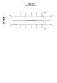
- FIG. 5 is a diagram schematically illustrating a section of the concrete bridge cut in the width direction.
- FIG. 6 is a diagram schematically illustrating a section of the iron bridge cut in the width direction.
- FIG. 7 is a diagram illustrating a part of the main girder of the sensor device and the bridge.
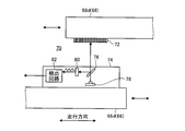
- FIG. 8 is a diagram illustrating the displacement detection device together with the first member and the second member.
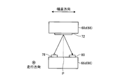
- FIG. 9 is a diagram illustrating an arrangement of a light emitting unit and a light receiving unit in a detector that does not include a half mirror.
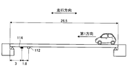
- FIG. 10 is a diagram illustrating an arrangement of the first sensor device and the second sensor device when the bridge is viewed from the side.
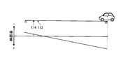
- FIG. 11 is a diagram illustrating the amount of expansion and contraction at each position on the bridge immediately after the vehicle enters the bridge.
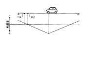
- FIG. 12 is a diagram showing the amount of expansion and contraction at each position on the bridge when the amount of expansion and contraction measured by the first sensor device is 0.
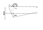
- FIG. 13 is a diagram illustrating the amount of expansion and contraction at each position on the bridge when the amount of expansion and contraction measured by the first sensor device is maximized.
- FIG. 10 is a diagram illustrating an arrangement of the first sensor device and the second sensor device when the bridge is viewed from the side.
- FIG. 11 is a diagram illustrating the amount of expansion and contraction at each position on the bridge immediately after the vehicle enters the bridge.
- FIG. 12 is a diagram showing
- FIG. 14 is a diagram illustrating the amount of expansion and contraction at each position on the bridge when the amount of expansion and contraction measured by the second sensor device is maximized.
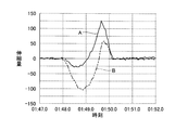
- FIG. 15 is a diagram illustrating a change in the amount of expansion and contraction measured by the first sensor device and the second sensor device when the vehicle passes through the bridge.
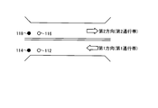
- FIG. 16 is a diagram illustrating an arrangement of the first sensor device, the second sensor device, the third sensor device, and the fourth sensor device when the bridge is viewed from above.
- FIG. 17 is a diagram illustrating a change in the amount of expansion and contraction measured by the first sensor device and the second sensor device when the vehicle passes through the first lane.
- FIG. 18 is a diagram illustrating a change in the amount of expansion and contraction measured by the third sensor device and the fourth sensor device when the vehicle passes through the first lane.
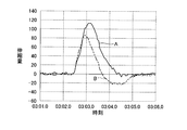
- FIG. 19 is a diagram illustrating a change in the amount of expansion and contraction measured by the first sensor device and the second sensor device when the vehicle passes through the second lane.
- FIG. 20 is a diagram illustrating a change in the amount of expansion and contraction measured by the third sensor device and the fourth sensor device when the vehicle passes through the second lane.
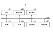
- FIG. 21 is a diagram illustrating a hardware configuration of the analysis device.
- FIG. 1 is a diagram showing a vehicle detection system 10 according to the embodiment.
- the vehicle detection system 10 detects the passage of a vehicle on a bridge.
- the vehicle detection system 10 includes a plurality of sensor devices 20, a collection device 22, a transmission device 24, a data storage device 26, and an analysis device 30.
- Each of the plurality of sensor devices 20 is attached to a bridge.
- Each of the sensor devices 20 measures the amount of change (the amount of expansion and contraction between two points) of the distance between two points in the running direction on the bridge at the attached position.
- the distance between the two points is, for example, about several tens of centimeters.
- the amount of change (the amount of expansion or contraction) is, for example, about several nanometers to several hundred nanometers.
- the collection device 22 collects the expansion and contraction amount between two points measured by each of the plurality of sensor devices 20 in association with the measured time. For example, the collection device 22 continuously acquires the amount of expansion and contraction measured by each of the plurality of sensor devices 20 at predetermined sample intervals. For example, the expansion / contraction amount is obtained at intervals of several milliseconds. In addition, for example, the collection device 22 always (for example, continuously for 24 hours) acquires the expansion / contraction amount measured by each of the plurality of sensor devices 20.
- the transmission device 24 transmits the information collected by the collection device 22 to the data storage device 26 via the network.
- the network may be wired, wireless, or a mixture of wired and wireless.
- the network is, for example, a LAN (Local Area Network), a VPN (Virtual Private Network), or a WAN (Wide Area Network) to which the LAN is connected via a router.
- the network may include the Internet or a telephone communication line.
- the data storage device 26 stores information received from the transmission device 24.
- the data storage device 26 is a computer such as a server device connectable to a network.
- the analysis device 30 reads information stored in the data storage device 26. Then, the analysis device 30 detects the passage of the vehicle based on the amount of expansion and contraction between the two points measured by each of the plurality of read sensor devices 20. For example, the analysis device 30 detects a time at which the vehicle has passed a predetermined position on the bridge, a speed of the vehicle that has passed, a moving direction of the vehicle that has passed, a weight of the vehicle that has passed, and a lane where the vehicle that has passed has traveled. I do.
- the analysis device 30 is a computer such as a server device connectable to a network.
- the analysis device 30 may be provided in the same housing as the data storage device 26.
- the analysis device 30 may be a single computer, or may be configured by a plurality of computers such as a cloud system.
- FIG. 2 is a diagram showing a functional configuration of the analysis device 30.
- the analysis device 30 includes a waveform acquisition unit 32, a passage time detection unit 34, a speed detection unit 36, a movement direction detection unit 38, a weight detection unit 40, a traffic zone determination unit 42, and an output unit 44. .
- the waveform acquisition unit 32 extracts a signal waveform when the vehicle passes through the bridge from the signals measured by each of the plurality of sensor devices 20 stored in the data storage device 26. Specifically, the waveform acquisition unit 32 extracts a signal waveform including a period from when the vehicle enters the bridge to when the vehicle exits the bridge.
- the passing time detector 34 analyzes the extracted signal waveform and detects the time at which the vehicle has passed a predetermined position on the bridge. For example, the passing time detecting unit 34 detects a time when the vehicle enters the bridge, a time when the vehicle passes a predetermined position on the bridge, and a time when the vehicle leaves the bridge.
- the speed detector 36 analyzes the extracted signal waveform to detect the speed of the vehicle passing through the bridge. For example, the speed detecting unit 36 detects an average speed of the vehicle that has passed through the bridge, and a speed when the vehicle has passed a predetermined position on the bridge.
- the moving direction detecting unit 38 analyzes the extracted signal waveform to detect the moving direction of the vehicle passing through the bridge. For example, the movement direction detection unit 38 determines whether a vehicle that has passed through the bridge has moved in a first direction (for example, an up direction) on the bridge, or a vehicle that has moved in a second direction (for example, a down direction) that is opposite to the first direction. ) Is detected.
- a first direction for example, an up direction
- a second direction for example, a down direction
- the weight detection unit 40 analyzes the extracted signal waveform to detect the weight of the vehicle passing through the bridge. For example, the weight detection unit 40 determines whether the vehicle that has passed through the bridge is small, medium, or large.
- the traffic zone determination unit 42 analyzes the extracted signal waveform to determine the traffic zone in which the vehicle has traveled. For example, the traffic lane determination unit 42 determines whether the vehicle has traveled in a first traffic lane (for example, an up-only lane) or a vehicle that has traveled in a second traffic lane (for example, a down-only lane) different from the first lane. It is determined whether the vehicle has run.
- a first traffic lane for example, an up-only lane
- a second traffic lane for example, a down-only lane
- the output unit 44 outputs detection results and determination results by the passage time detection unit 34, the speed detection unit 36, the movement direction detection unit 38, the weight detection unit 40, and the traffic zone determination unit 42 to an external device. For example, the output unit 44 outputs a detection result and a determination result to the monitor device.
- FIG. 3 is a diagram showing the arrangement of the plurality of sensor devices 20 when the bridge is viewed from the side.
- the plurality of sensor devices 20 are attached to an end portion side of the center of the bridge in the traveling direction.
- the plurality of sensor devices 20 are attached, for example, on the lower surface of the bridge and near the abutment. Thereby, the worker can easily attach the plurality of sensor devices 20 to the bridge even after the bridge is completed.
- FIG. 4 is a diagram showing an arrangement of the plurality of sensor devices 20 when the bridge is viewed from above.
- the plurality of sensor devices 20 form a set of two sensor devices 20 and are attached to a bridge for each set.
- the pair of two sensor devices 20 are mounted at the same position in the width direction of the bridge and at different positions in the running direction of the bridge.
- the pair of two sensor devices 20 are arranged, for example, at an interval of about half that of a general vehicle. Thereby, the pair of two sensor devices 20 can output a signal waveform having an approximate waveform and a phase shift when the vehicle passes.
- two sets of sensor devices 20 are attached to one end of the bridge in the traveling direction, but two sets of sensor devices 20 are attached to both ends of the bridge. You may.
- FIG. 5 is a diagram schematically showing a section of the concrete bridge cut in the width direction.
- the bridge includes a floor slab 52 and a plurality of main girders 54.
- the plurality of sensor devices 20 are attached to the lower surface 56 of any main girder 54 in the bridge.
- the sensor device 20 is attached to the lower surface 56 of the main girder 54 with bolts or the like.
- the collection device 22 is housed in a housing for waterproofing and dustproofing.
- the housing accommodating the collecting device 22 is mounted on a channel steel 58 attached so as to bridge two adjacent main girders 54.
- the channel steel 58 has both ends attached to the lower surfaces 56 of two adjacent main girders 54 by bolts. Thereby, the collecting device 22 can collect the signals output from each of the plurality of sensor devices 20.
- the transmitting device 24 may be attached to a bridge, or may be attached to a column or the like close to the bridge.
- FIG. 6 is a diagram schematically showing a section of the iron bridge cut in the width direction.
- the sensor device 20 is attached to the lower surface 56 of the lower flange 60 of the main girder 54 by a magnet or the like.
- both ends of the channel steel 58 are placed on the upper surface of the lower flange 60 of the two adjacent main girders 54. Further, the channel steel 58 may be attached to the lower flange 60 by, for example, a magnet.
- FIG. 7 is a diagram showing a part of the sensor device 20 and the main girder 54 of the bridge.
- the sensor device 20 measures the amount of change (the amount of expansion or contraction) of the distance between the first point 62 and the second point 64 on the lower surface 56 of the main girder 54 of the bridge.
- the first point 62 and the second point 64 are the same position in the width direction of the bridge and different positions in the running direction.
- the distance between the first point 62 and the second point 64 is about several tens of centimeters. In the present embodiment, it is 35 cm.
- the sensor device 20 measures a change (an amount of expansion and contraction) in the traveling direction between the first point 62 and the second point 64 in a unit of, for example, several nanometers to several hundred nanometers.
- the sensor device 20 includes a first member 66, a second member 68, and a displacement detection device 70.
- the first member 66 is a cantilever having a support portion 66a and a beam portion 66b.
- One end of the support portion 66a is a fixed end 66c fixed to the first point 62.
- the support portion 66a extends from the first point 62 by a predetermined distance vertically below the lower surface 56 of the main girder 54.
- the beam 66b extends a predetermined distance from the end of the support 66a opposite to the fixed end 66c toward the second point 64 in the traveling direction.
- the end of the beam 66b on the side not connected to the support 66a is a free end 66d not connected to any member.
- the free end 66d of the first member 66 is arranged near the approximate center of a line connecting the first point 62 and the second point 64.
- the second member 68 is a cantilever having a support portion 68a and a beam portion 68b.
- One end of the support portion 68a is a fixed end 68c fixed to the second point 64.
- the support portion 68 a extends from the second point 64 by a predetermined distance vertically below the lower surface 56 of the main girder 54.
- the beam portion 68b extends a predetermined distance from the end of the support portion 68a opposite to the fixed end 68c toward the first point 62 in the traveling direction.
- the end of the beam portion 68b on the side not connected to the support portion 68a is a free end 68d not connected to any member.
- the free end 68d of the second member 68 is disposed near the approximate center of a line connecting the first point 62 and the second point 64.
- the free end 66d of the first member 66 and the free end 68d of the second member 68 do not cause mechanical interference, and are arranged at positions overlapping in the traveling direction.
- the free end 66d of the first member 66 and the free end 68d of the second member 68 are arranged at positions facing each other in a direction perpendicular to the lower surface 56 of the main girder 54.
- the sensor device 20 shown in FIG. 7 has a configuration in which both the first member 66 and the second member 68 are cantilever beams.
- the second member 68 may be a cantilever, and the first member 66 may not be a cantilever.
- the second member 68 is disposed at a position where the free end 68d overlaps at least a part of the first member 66 in the traveling direction without mechanical interference. Even in such a configuration, when the distance between the first point 62 and the second point 64 changes, the relative position between the free end 68d of the first member 66 and the second member 68 is changed in the traveling direction. Shift.
- the displacement detection device 70 is provided at a portion where the free end 66d of the first member 66 and the free end 68d of the second member 68 face each other.
- the displacement detection device 70 detects displacement of a relative position between the free end 66d of the first member 66 and the free end 68d of the second member 68. Then, the displacement detection device 70 outputs the detected displacement as the amount of expansion and contraction between two points in the running direction on the bridge.
- FIG. 8 is a diagram showing the displacement detection device 70 together with the first member 66 and the second member 68.
- the displacement detection device 70 includes an optical element 72 and a detector 74.
- the optical element 72 is attached to one of the free end 66d of the first member 66 and the free end 68d of the second member 68.
- the detector 74 is attached to the other of the free end 66d of the first member 66 and the free end 68d of the second member 68 to which the optical element 72 is not attached.
- the optical element 72 is an optical member whose reflected light amount (or transmitted light amount) changes according to the light irradiation position with respect to the traveling direction.
- the optical element 72 is a mirror having a surface coated with a plurality of light absorbing materials (stripe) at predetermined intervals in the running direction.
- the optical element 72 may be a diffraction grating in which a plurality of optical slits (stripe) are formed at predetermined intervals in the traveling direction.
- the detector 74 includes a half mirror 76, a light emitting unit 78, a light receiving unit 80, and a detection circuit 82.
- the half mirror 76 reflects a part of the irradiated light and transmits another part.
- the light emitting section 78 irradiates the optical element 72 with light via the half mirror 76.
- the light receiving unit 80 receives the light reflected by the optical element 72 via the half mirror 76.
- the detection circuit 82 outputs a signal representing the displacement of the relative position between the first member 66 and the second member 68 based on the change in the amount of light detected by the light receiving section 80 as the amount of expansion and contraction.
- the position of the light applied to the optical element 72 is shifted in the running direction in accordance with the shift of the relative position between the first member 66 and the second member 68 in the running direction. Since stripes are formed in the optical element 72 in the traveling direction, the amount of reflected light from the optical element 72 increases or decreases according to the shift of the light irradiation position in the traveling direction. Specifically, the amount of light reflected by the optical element 72 increases or decreases by one cycle when the position of the light applied to the optical element 72 is shifted by the interval of the stripe. Therefore, for example, the detection circuit 82 can obtain the amount of change in the relative position between the first member 66 and the second member 68 by counting the increase or decrease in the signal output from the light receiving unit 80.
- the displacement detecting device 70 may include two optical elements 72 whose stripes are shifted from each other by 1 / period, two light emitting units 78 and two light receiving units 80 corresponding to the two optical elements 72. Accordingly, the two light receiving units 80 can output two periodic signals that are shifted by 1/4 periodic phase with respect to a change in the relative position between the first member 66 and the second member 68. Therefore, for example, the detection circuit 82 determines, based on the values of the two signals, the direction of change in the relative position between the first member 66 and the second member 68, and the first member 66 at an interval shorter than the stripe cycle. The amount of change in the relative position with respect to the second member 68 can be detected.
- the optical element 72 is configured to reflect light.
- the optical element 72 may be configured to transmit light.
- the transmitted light amount of the optical element 72 changes according to the light irradiation position with respect to the traveling direction.
- the optical element 72 may be glass, plastic, or the like having a surface coated with a plurality of light absorbing materials (stripe) at predetermined intervals in the traveling direction. In such a case, the light receiving section 80 receives the light transmitted through the optical element 72.
- the detector 74 may not include the half mirror 76.
- FIG. 9 is a diagram showing the arrangement of the light emitting unit 78 and the light receiving unit 80 in the detector 74 not including the half mirror 76.
- the detector 74 is provided on the first member 66.
- the optical element 72 is provided on the second member 68.
- the position of the first member 66 facing the center of the optical element 72 in the width direction is P.
- the light emitting unit 78 is disposed at a position on the first member 66 that is shifted from the P by a predetermined distance in the width direction.
- the light receiving unit 80 is arranged at a position shifted from P by a predetermined distance in the width direction to the opposite side to the light emitting unit 78.
- the light emitting section 78 emits light in a direction toward the center in the width direction of the optical element 72.
- the optical element 72 receives light from the light emitting unit 78 at a predetermined angle, and reflects the incident light toward the light receiving unit 80. Then, the light receiving section 80 receives the light reflected by the optical element 72.
- Such a detector 74 can have the same function as the configuration shown in FIG.
- the displacement detection device 70 having such a configuration can be attached to the lower surface 56 of the main girder 54 in a bridge.
- the displacement detection device 70 can be attached from the outside without embedding an elastic member in a bridge unlike a strain gauge. Thereby, the displacement detection device 70 can be attached later to the completed bridge. Further, the displacement detection device 70 can be attached without reducing the strength of the bridge. In addition, the displacement detection device 70 can easily perform maintenance even after attachment.
- the displacement detecting device 70 having such a configuration detects a change in the distance between two points using an optical sensor using a cantilever. Accordingly, the displacement detection device 70 can accurately detect a very small expansion and contraction in the bridge using a member having a simple configuration and a low cost.
- FIG. 10 is a diagram showing the arrangement of the first sensor device 112 and the second sensor device 114 when the bridge is viewed from the side.
- the first sensor device 112 and the second sensor device 114 are one set of the plurality of sensor devices 20 attached to the bridge.
- the first sensor device 112 and the second sensor device 114 are arranged at the same position in the width direction of the bridge, and are arranged at different positions in the traveling direction.
- the first sensor device 112 is disposed closer to the center in the traveling direction than the second sensor device 114 is.
- the second sensor device 114 is arranged at a position 3 m from an end of a bridge having a bridge length of 26.5 m.
- the distance between the first sensor device 112 and the second sensor device 114 is 1.8 m.
- the first direction is from the end opposite to the end where the first sensor device 112 and the second sensor device 114 are arranged to the end side where the first sensor device 112 and the second sensor device 114 are arranged.
- the direction of movement In this case, each position in the traveling direction on the bridge expands and contracts as shown in FIGS.
- FIG. 11 is a diagram showing the amount of expansion and contraction at each position on the bridge immediately after the vehicle enters the bridge. Immediately after the vehicle enters the bridge, the end opposite to the first sensor device 112 and the second sensor device 114 extends the most. Immediately after the vehicle enters the bridge, the ends on the side of the first sensor device 112 and the second sensor device 114 contract.
- FIG. 12 is a diagram showing the amount of expansion and contraction at each position on the bridge when the amount of expansion and contraction measured by the first sensor device 112 is 0.
- the portion of the bridge where the first sensor device 112 is installed has zero expansion and contraction. In this case, the amount of expansion and contraction measured by the first sensor device 112 is zero.
- FIG. 13 is a diagram showing the amount of expansion and contraction at each position on the bridge when the amount of expansion and contraction measured by the first sensor device 112 is maximized.
- the vehicle is located at a predetermined location near the first sensor device 112 on the bridge, the portion of the bridge where the first sensor device 112 is installed extends most. In this case, the amount of expansion and contraction measured by the first sensor device 112 becomes the maximum value.
- FIG. 14 is a diagram showing the amount of expansion and contraction at each position on the bridge when the amount of expansion and contraction measured by the second sensor device 114 is maximized.
- the portion of the bridge where the second sensor device 114 is installed extends most. In this case, the amount of expansion and contraction measured by the second sensor device 114 becomes the maximum value.
- the characteristics of the bridge shown in FIGS. 11 to 14 are estimated to be constant regardless of the weight of the vehicle or the speed of the vehicle when the arrangement of the first sensor device 112 and the second sensor device 114 is fixed. Is done.
- FIG. 15 shows a time change (A) of the amount of expansion and contraction measured by the first sensor device 112 and a time change of the amount of expansion and contraction measured by the second sensor device 114 when the vehicle moves on the bridge in the first direction ( It is a figure which shows B).
- the amount of expansion and contraction measured by the first sensor device 112 changes as shown in the waveform of A in FIG. That is, the expansion / contraction amount measured by the first sensor device 112 starts to change from 0 (S11), gradually decreases (S12), and reaches a minimum at a certain point (S13). Subsequently, the amount of expansion and contraction measured by the first sensor device 112 increases (S14), crosses zero (S15), and reaches a maximum at a certain point (S16). The maximum value of the deformation amount is V 1. Subsequently, the amount of expansion and contraction measured by the first sensor device 112 decreases (S17), and finally becomes 0 to end the change (S18).
- the amount of expansion and contraction measured by the second sensor device 114 changes as shown in the waveform of B in FIG. That is, the amount of expansion and contraction measured by the second sensor device 114 starts to change from 0 (S21), gradually decreases (S22), and reaches a minimum at a certain point (S23). Subsequently, the amount of expansion and contraction measured by the second sensor device 114 increases (S24), crosses zero (S25), and reaches a maximum at a certain point (S26). The maximum value of the deformation amount is V 2. The amount of expansion / contraction measured by the second sensor device 114 decreases (S27), and finally becomes 0 to end the change (S28).
- the change waveform of the amount of expansion and contraction measured by the first sensor device 112 is a waveform in which the positive and negative in the time direction are inverted.
- the change waveform of the amount of expansion and contraction measured by the second sensor device 114 is also a waveform in which the positive and negative in the time direction are inverted.
- the movement direction detection unit 38 of the analysis device 30 determines the time (S16) at which the expansion and contraction amount measured by the first sensor device 112 is the maximum and the time at which the expansion and contraction amount measured by the second sensor device 114 is the largest.
- the moving direction of the vehicle is determined based on the order of (S26). More specifically, the movement direction detection unit 38 of the analysis device 30 determines that the timing (S16) at which the amount of expansion and contraction measured by the first sensor device 112 is the maximum, and that the amount of expansion and contraction measured by the second sensor device 114 If earlier than the maximum timing (S26), it is determined that the vehicle is moving in the first direction.
- the movement direction detection unit 38 of the analysis device 30 determines that the timing (S26) at which the expansion and contraction amount measured by the second sensor device 114 is maximum is the timing at which the expansion and contraction amount measured by the first sensor device 112 is maximum. (S16) If earlier, it is determined that the vehicle is moving in the second direction.
- the analysis device 30 may determine the moving direction of the vehicle by comparing the timing at which the amount of expansion and contraction is minimum, instead of the timing at which the amount of expansion and contraction is maximum.
- the analysis device 30 may determine the moving direction of the vehicle by comparing the timing at which the expansion / contraction amount crosses 0 instead of the timing at which the expansion / contraction amount becomes maximum.
- the change start timings (S11 and S21) of the expansion / contraction amount measured by the first sensor device 112 and the second sensor device 114 are simultaneous.
- the change start timing of the expansion / contraction amount measured by the first sensor device 112 and the second sensor device 114 is estimated to be the timing at which the vehicle enters the end of the bridge. Therefore, the passage time detection unit 34 of the analysis device 30 detects the time at which the vehicle enters the bridge based on the change start timing of the amount of expansion and contraction measured by the first sensor device 112 and the second sensor device 114.
- the change end timings (S18 and S28) of the expansion / contraction amount measured by the first sensor device 112 and the second sensor device 114 are simultaneous.
- the end timing of the change in the amount of expansion and contraction measured by the first sensor device 112 and the second sensor device 114 is estimated to be the timing at which the vehicle exits the end of the bridge. Therefore, the passage time detection unit 34 of the analysis device 30 detects the exit time of the vehicle from the bridge based on the change end timing of the expansion and contraction amount measured by the first sensor device 112 and the second sensor device 114.
- the speed detection unit 36 of the analysis device 30 calculates the passing time of the vehicle through the bridge by subtracting the vehicle entry time into the bridge (S11 and S21) from the vehicle exiting time from the bridge (S18 and S28). .
- the bridge length of the bridge is known. Therefore, the speed detection unit 36 of the analysis device 30 calculates the speed of the vehicle by dividing the bridge length by the passing time.
- the average speed of the vehicle is calculated by taking an average value from data obtained by repeating this measurement a plurality of times.
- the position (first intermediate position) of the vehicle at the timing (S15) at which the expansion / contraction amount measured by the first sensor device 112 crosses zero is estimated to be constant regardless of the speed of the vehicle and the weight of the vehicle. Further, the position of the vehicle (second intermediate position) at the timing (S25) at which the expansion / contraction amount measured by the second sensor device 114 crosses zero is estimated to be constant regardless of the speed of the vehicle and the weight of the vehicle. .
- the analysis device 30 acquires the first intermediate position prior to the measurement processing (for example, in a preparation stage of measurement). For example, prior to the measurement process, the analysis device 30 may be configured to use an image captured by a camera to capture the position (first intermediate position) of the vehicle at the timing when the amount of expansion / contraction measured by the first sensor device 112 becomes 0, and the first sensor It is calculated from the signal waveform of the device 112. Then, at the time of measurement, the passage time detection unit 34 of the analysis device 30 detects the time at which the vehicle has passed the first intermediate position based on the timing at which the amount of expansion and contraction measured by the first sensor device 112 crosses zero. .
- the analysis device 30 acquires the second intermediate position prior to the measurement processing. For example, prior to the measurement processing, the analysis device 30 may use a camera and a second sensor to capture the position (second intermediate position) of the vehicle at the timing when the amount of expansion / contraction measured by the second sensor device 114 becomes zero. It is calculated from the signal waveform of the device 114. Then, at the time of measurement, the passage time detection unit 34 of the analysis device 30 detects the time at which the vehicle has passed the second intermediate position based on the timing at which the amount of expansion and contraction measured by the second sensor device 114 crosses zero. .
- the position (first maximum position) of the vehicle at the timing (S16) at which the amount of expansion and contraction measured by the first sensor device 112 becomes maximum is estimated to be constant regardless of the speed of the vehicle and the weight of the vehicle. Further, it is estimated that the position of the vehicle (second maximum position) at the timing (S26) at which the amount of expansion and contraction measured by the second sensor device 114 is maximum is constant regardless of the speed of the vehicle and the weight of the vehicle. .
- the analysis device 30 acquires the first maximum position prior to the measurement processing. For example, prior to the measurement process, the analysis device 30 determines the position (first maximum position) of the vehicle at the timing when the amount of expansion and contraction measured by the first sensor device 112 is the maximum, with the image captured by the camera and the first sensor. It is calculated from the signal waveform of the device 112. Then, at the time of measurement, the passage time detection unit 34 of the analysis device 30 detects the time at which the vehicle has passed the first maximum position based on the timing at which the amount of expansion and contraction measured by the first sensor device 112 is maximum.
- the analysis device 30 acquires the second maximum position before the measurement processing. For example, prior to the measurement processing, the analysis device 30 determines the position (second maximum position) of the vehicle at the timing when the amount of expansion and contraction measured by the second sensor device 114 is the maximum, with the image captured by the camera and the second sensor. It is calculated from the signal waveform of the device 114. Then, at the time of measurement, the passage time detection unit 34 of the analysis device 30 detects the time at which the vehicle has passed the second maximum position based on the timing at which the amount of expansion and contraction measured by the second sensor device 114 is maximum.
- the analysis device 30 replaces the position of the vehicle with the timing at which the amount of expansion and contraction becomes maximum, and replaces the position of the vehicle at the timing with which the amount of expansion and contraction measured by the first sensor device 112 or the second sensor device 114 becomes minimum (the (1st minimum position or 2nd minimum position) may be detected. Then, the passage time detection unit 34 of the analysis device 30 may detect the time at which the vehicle has passed the first minimum position or the second minimum position based on the timing at which the amount of expansion and contraction is minimum.
- the speed detection unit 36 of the analysis device 30 subtracts the time (S16) at which the vehicle passed through the first maximum position from the time (S26) at which the vehicle passed through the second maximum position, thereby obtaining the second value from the first maximum position. Calculate the transit time to the maximum position. In addition, the analysis device 30 acquires the first maximum position and the second maximum position in advance. The speed detection unit 36 of the analysis device 30 calculates the speed of the vehicle by dividing the distance obtained by subtracting the first maximum position from the second maximum position by the passing time from the first maximum position to the second maximum position. .
- the analysis device 30 acquires the maximum value (V 1 ) of the amount of expansion and contraction measured by the first sensor device 112 and the relationship between the weight of the vehicle. For example, the analysis device 30 determines the type of weight (for example, a small car, a medium-sized car, and a large car) of the vehicle passing through the bridge based on the image captured by the camera for each of the plurality of vehicles. Further, the analysis device 30 creates a correspondence relationship between the determination result of each of the plurality of vehicles and the maximum value (V 1 ) of the amount of expansion and contraction measured by the first sensor device 112 when the vehicle passes. . Then, the analysis device 30 generates a threshold that divides the weight of the vehicle based on the created correspondence.
- V 1 the maximum value
- the analysis device 30 generates a threshold that separates a small vehicle from a medium vehicle and a threshold that separates a medium vehicle from a large vehicle. Thereby, the analysis device 30 can acquire the relationship between the maximum value (V 1 ) of the amount of expansion and contraction measured by the first sensor device 112 and the weight of the vehicle.
- the weight detection unit 40 of the analysis device 30 determines the weight of the passing vehicle based on the maximum value (V 1 ) of the amount of expansion and contraction measured by the first sensor device 112 and the correspondence created in advance. (For example, a small car, a medium car or a large car) is detected.
- the analysis device 30 uses the maximum value (V 2 ) of the amount of expansion and contraction measured by the second sensor device 114 instead of the maximum value (V 1 ) of the amount of expansion and contraction measured by the first sensor device 112.
- the weight of the passing vehicle may be detected.
- the analysis device 30 prior to the measurement processing, similarly determines the correspondence between the type of the weight of the vehicle passing through the bridge and the maximum value (V 2 ) of the amount of expansion and contraction measured by the second sensor device 114. Create Then, at the time of measurement, the weight detection unit 40 of the analysis device 30 determines the weight of the passing vehicle based on the maximum value (V 2 ) of the amount of expansion and contraction measured by the second sensor device 114 and the correspondence created in advance. Is detected.
- FIG. 16 is a diagram showing the arrangement of the first sensor device 112, the second sensor device 114, the third sensor device 116, and the fourth sensor device 118 when the bridge is viewed from above.
- the first sensor device 112 and the second sensor device 114 are one set of the plurality of sensor devices 20 attached to the bridge.
- the third sensor device 116 and the fourth sensor device 118 are one set of the plurality of sensor devices 20 attached to the bridge.
- the third sensor device 116 and the fourth sensor device 118 are arranged at the same position in the width direction of the bridge, and are arranged at different positions in the traveling direction.
- the third sensor device 116 is disposed closer to the center in the traveling direction than the fourth sensor device 118 is.
- the first sensor device 112 and the third sensor device 116 are arranged at the same position in the traveling direction. Further, the second sensor device 114 and the fourth sensor device 118 are arranged at the same position in the traveling direction.
- the set of the first sensor device 112 and the second sensor device 114 is provided in the first traffic zone.
- a set of the third sensor device 116 and the fourth sensor device 118 is provided in the second lane.
- the first lane is a lane where the vehicle must travel in the first direction.
- the second lane is a lane where the vehicle must travel in the second direction.
- FIG. 17 is a diagram illustrating a change in the amount of expansion and contraction measured by the first sensor device 112 and the second sensor device 114 when the vehicle travels in the first lane in the first direction.
- the amount of expansion and contraction measured by the first sensor device 112 and the second sensor device 114 decreases, becomes the minimum value, and increases as shown in FIG. , 0 cross, the maximum value, and a decreasing waveform.
- FIG. 18 is a diagram showing a change in the amount of expansion and contraction measured by the third sensor device 116 and the fourth sensor device 118 when the vehicle travels in the first lane in the first direction.
- the amount of expansion and contraction measured by the third sensor device 116 and the fourth sensor device 118 is, as shown in FIG. Similar to the device 114, the waveform decreases, reaches the minimum value, increases, passes through the zero cross, reaches the maximum value, and decreases.
- the amount of expansion and contraction measured by the third sensor device 116 and the fourth sensor device 118 is measured by the first sensor device 112 and the second sensor device 114.
- the amplitude of the maximum value and the minimum value is small and the noise is large as compared with the expanded / contracted amount.
- FIG. 19 is a diagram showing a change in the amount of expansion and contraction measured by the first sensor device 112 and the second sensor device 114 when the vehicle travels in the second lane in the second direction.
- the amount of expansion and contraction measured by the first sensor device 112 and the second sensor device 114 increases as shown in FIG. , And has a minimum value and an increasing waveform.
- FIG. 20 is a diagram showing a change in the amount of expansion and contraction measured by the third sensor device 116 and the fourth sensor device 118 when the vehicle travels in the second lane in the second direction.
- the amount of expansion and contraction measured by the third sensor device 116 and the fourth sensor device 118 is, as shown in FIG.
- the waveform increases and reaches the maximum value, passes through the zero cross, reaches the minimum value, and has an increasing waveform.
- the amount of expansion and contraction measured by the third sensor device 116 and the fourth sensor device 118 is measured by the first sensor device 112 and the second sensor device 114.
- the amplitude of the maximum value and the minimum value is large and the noise is small as compared with the expanded / contracted amount.
- the waveform of the amount of expansion and contraction measured by the first sensor device 112 was measured by the third sensor device 116.
- the maximum value and the amplitude are larger and the noise is smaller than the waveform of the amount of expansion and contraction.
- the waveform of the amount of expansion and contraction measured by the third sensor device 116 is larger than the waveform of the amount of expansion and contraction measured by the first sensor device 112. High amplitude and low noise. The same applies to the relationship between the second sensor device 114 and the fourth sensor device 118.
- the traffic zone determination unit 42 of the analysis device 30 determines whether the bridge has a maximum value of the amount of expansion and contraction measured by the first sensor device 112 and a maximum value of the amount of expansion and contraction measured by the third sensor device 116. To detect the lane in which the vehicle that has passed has traveled. In addition, the traffic zone determination unit 42 of the analysis device 30 determines whether or not the maximum value of the amount of expansion and contraction measured by the second sensor device 114 and the maximum value of the amount of expansion and contraction measured by the fourth sensor device 118 are different from each other. The traffic zone in which the vehicle that has passed through travels may be detected.
- the analysis device 30 can detect the passage of the vehicle based on the amount of expansion and contraction between two points measured by each of the plurality of read sensor devices 20. For example, the analysis device 30 detects a time at which the vehicle has passed a predetermined position on the bridge, a speed of the vehicle that has passed, a moving direction of the vehicle that has passed, a weight of the vehicle that has passed, and a lane where the vehicle that has passed has traveled. can do.
- FIG. 21 is a diagram illustrating a hardware configuration of the analysis device 30.
- the analysis device 30 is realized by, for example, a hardware configuration similar to a general computer.
- the analysis device 30 includes a CPU (Central Processing Unit) 201, an operation device 202, a display device 203, a ROM (Read Only Memory) 204, a RAM (Random Access Memory) 205, a storage device 206, and a communication device 207. And a bus 209. Each unit is connected by a bus 209.
- the CPU 201 executes various processes in cooperation with various programs stored in advance in the ROM 204 or the storage device 206 using a predetermined area of the RAM 205 as a work area, and comprehensively controls the operation of each unit configuring the analysis device 30.
- the CPU 201 operates the operation device 202, the display device 203, the communication device 207, and the like in cooperation with a program stored in the ROM 204 or the storage device 206 in advance.
- the operation device 202 is an input device such as a touch panel, a mouse, and a keyboard.
- the operation device 202 receives, as an instruction signal, information input by a user and outputs the instruction signal to the CPU 201.
- the display device 203 is a display unit such as an LCD (Liquid Crystal Display).
- the display device 203 displays various information based on a display signal from the CPU 201. For example, the display device 203 displays the time when the vehicle passed a predetermined position on the bridge, the speed of the vehicle that passed, the moving direction of the vehicle that passed, the weight of the vehicle that passed, and the lane where the vehicle that passed the vehicle ran. I do.
- the ROM 204 non-rewritably stores a program used for controlling the analyzer 30 and various setting information.
- the RAM 205 is a volatile storage medium such as an SDRAM (Synchronous Dynamic Random Access Memory).
- SDRAM Serial Dynamic Random Access Memory
- the RAM 205 functions as a work area for the CPU 201.
- the storage device 206 is a rewritable recording device such as a semiconductor storage medium such as a flash memory or a magnetically or optically recordable storage medium.
- the storage device 206 stores a program used for controlling the analysis device 30.
- the communication device 207 transmits and receives data to and from another device.
- the communication device 207 may transmit and receive data to and from a server or the like via a network.
- the program executed by the analysis device 30 of the present embodiment is stored on a computer connected to a network such as the Internet, and is provided by being downloaded via the network. Further, the program executed by the analysis device 30 of the present embodiment may be provided by being incorporated in a portable storage medium or the like in advance.
- the program executed by the analysis device 30 of the present embodiment includes a waveform acquisition module, a passing time detection module, a speed detection module, a movement direction detection module, a weight detection module, a traffic zone determination module, and an output module.
- the module configuration includes The CPU 201 (processor) reads such a program from a storage medium or the like and loads each of the modules into the RAM 205 (main storage device).
- the CPU 201 (processor) executes such a program to execute the waveform acquisition unit 32, the passing time detection unit 34, the speed detection unit 36, the movement direction detection unit 38, the weight detection unit 40, and the traffic zone determination unit 42. And functions as the output unit 44.
- some or all of the waveform acquisition unit 32, the passage time detection unit 34, the speed detection unit 36, the movement direction detection unit 38, the weight detection unit 40, the traffic zone determination unit 42, and the output unit 44 are configured by hardware. You may.
Landscapes
- Physics & Mathematics (AREA)
- General Physics & Mathematics (AREA)
- Engineering & Computer Science (AREA)
- Architecture (AREA)
- Civil Engineering (AREA)
- Structural Engineering (AREA)
- Traffic Control Systems (AREA)
- Bridges Or Land Bridges (AREA)
- Length Measuring Devices By Optical Means (AREA)
Abstract
車両検出システムは、橋梁における車両の通過を低コストで精度良く検出する。車両検出システムは、橋梁における車両の通過を検出する車両検出システムであって、橋梁における走行方向の2点間の伸縮量を測定する複数のセンサ装置と、複数のセンサ装置のそれぞれにより測定された2点間の伸縮量に基づき車両の通過を検出する解析装置と、を備える。複数のセンサ装置のそれぞれは、橋梁における第1点に固定された第1部材と、固定端が橋梁における第1点から走行方向に離間した第2点に固定され、自由端が第1部材の少なくとも一部と走行方向に重なる位置に配置された片持梁である第2部材と、第1部材と第2部材の自由端との相対位置の変位を検出し、検出した前記変位を前記伸縮量として出力する変位検出装置と有する。
Description
本発明は、車両検出システム、車両検出方法、解析装置およびプログラムに関する。
従来、橋梁は、5年に1回程度、目視により点検がされている。橋梁の安全性をより高めるためには、例えば橋梁を走行する車両を常時モニタリングし、モニタリング結果に基づき橋梁の将来の状態等を予測して、橋梁を計画的に管理する必要がある。
特許文献1には、交通路の横断方向における車両の走行位置を歪計を用いて検出する技術が記載されている。特許文献2には、車両が橋梁を通過する際の床版の歪みを歪計を用いて検出する技術が記載されている。特許文献3には、車両が橋梁を通過する際の床版の歪みを歪計を用いて検出し、検出した歪みに基づき車両の重量を算出する技術が記載されている。特許文献4には、車両が橋梁を通過する際の床版の歪みを歪計を用いて検出し、通過する車両の特性を検出する技術が記載されている。特許文献5には、橋梁における車両の通行を検出することを目的とした変位量計測装置が記載されている。
ところで、橋梁を管理する人員および予算は限られている。このため、橋梁を走行する車両を少ない人員および低コストでモニタリングする必要があった。
本発明は、上記に鑑みてなされたものであって、橋梁における車両の通過を低コストで精度良く検出する車両検出システム、車両検出方法、解析装置およびプログラムを提供することを目的とする。
上述した課題を解決し、目的を達成するために、本発明に係る車両検出システムは、橋梁における車両の通過を検出する車両検出システムであって、前記橋梁における走行方向の2点間の伸縮量を測定する複数のセンサ装置と、前記複数のセンサ装置のそれぞれにより測定された前記2点間の前記伸縮量に基づき前記車両の通過を検出する解析装置と、を備える。
本発明によれば、橋梁における車両の通過を精度良く検出することができる。
以下、図面を参照しながら実施形態に係る車両検出システム10について説明する。
図1は、実施形態に係る車両検出システム10を示す図である。車両検出システム10は、橋梁における車両の通過を検出する。
車両検出システム10は、複数のセンサ装置20と、収集装置22と、送信装置24と、データ蓄積装置26と、解析装置30とを備える。
複数のセンサ装置20のそれぞれは、橋梁に取り付けられる。それぞれのセンサ装置20は、取り付けられた位置において、橋梁における走行方向の2点間距離の変化量(2点間の伸縮量)を測定する。2点間距離は、例えば、数10センチメートル程度である。変化量(伸縮量)は、例えば、数ナノメートルから数100ナノメートル程度である。
収集装置22は、複数のセンサ装置20のそれぞれにより測定された2点間の伸縮量を、測定した時刻に対応付けて収集する。例えば、収集装置22は、複数のセンサ装置20のそれぞれにより測定された伸縮量を、所定のサンプル間隔毎に連続的に取得する。例えば、数ミリ秒間隔毎に伸縮量を取得する。また、例えば、収集装置22は、常時(例えば、24時間連続して)、複数のセンサ装置20のそれぞれにより測定された伸縮量を取得する。
送信装置24は、収集装置22により収集された情報をネットワークを介してデータ蓄積装置26に送信する。ネットワークは、有線であっても、無線であっても、有線と無線とが混在していてもよい。ネットワークは、例えば、LAN(Local Area Network)、VPN(Virtual Private Network)またはLANがルータを介して接続されたWAN(Wide Area Network)である。また、ネットワークは、インターネットまたは電話通信回線等を含んでいてもよい。
データ蓄積装置26は、送信装置24から受信した情報を記憶する。データ蓄積装置26は、ネットワークに接続可能なサーバ装置等のコンピュータである。
解析装置30は、データ蓄積装置26に蓄積された情報を読み出す。そして、解析装置30は、読み出した複数のセンサ装置20のそれぞれにより測定された2点間の伸縮量に基づき車両の通過を検出する。例えば、解析装置30は、橋梁における所定の位置を車両が通過した時刻、通過した車両の速度、通過した車両の移動方向、通過した車両の重量、および、通過した車両が走行した通行帯を検出する。
解析装置30は、ネットワークに接続可能なサーバ装置等のコンピュータである。解析装置30は、データ蓄積装置26と同一の筐体内に設けられていてもよい。解析装置30は、1台のコンピュータであってもよいし、クラウドシステムのように複数台のコンピュータにより構成されていてもよい。
図2は、解析装置30の機能構成を示す図である。解析装置30は、波形取得部32と、通過時刻検出部34と、速度検出部36と、移動方向検出部38と、重量検出部40と、通行帯判定部42と、出力部44とを有する。
波形取得部32は、データ蓄積装置26に記憶された複数のセンサ装置20のそれぞれにより測定された信号から、車両が橋梁を通過したときの信号波形を抽出する。具体的には、波形取得部32は、車両が橋梁に進入してから車両が橋梁から退出するまでの期間を含む信号波形を抽出する。
通過時刻検出部34は、抽出した信号波形を解析して、橋梁における所定の位置を車両が通過した時刻を検出する。例えば、通過時刻検出部34は、橋梁へ車両が進入した時刻、橋梁における予め定められた位置を車両が通過した時刻、および、橋梁から車両が退出した時刻を検出する。
速度検出部36は、抽出した信号波形を解析して、橋梁を通過した車両の速度を検出する。例えば、速度検出部36は、橋梁を通過した車両の平均速度、および、橋梁における予め定められた位置を車両が通過した時の速度を検出する。
移動方向検出部38は、抽出した信号波形を解析して、橋梁を通過した車両の移動方向を検出する。例えば、移動方向検出部38は、橋梁を通過した車両が、橋梁における第1方向(例えば上り方向)に移動したか、または、車両が、第1方向とは反対の第2方向(例えば下り方向)に移動したかを検出する。
重量検出部40は、抽出した信号波形を解析して、橋梁を通過した車両の重量を検出する。例えば、重量検出部40は、橋梁を通過した車両が、小型であるか、中型であるか、または、大型であるかを判別する。
通行帯判定部42は、抽出した信号波形を解析して、車両が走行した通行帯を判定する。例えば、通行帯判定部42は、第1通行帯(例えば、上り専用車線)を車両が走行したか、または、第1通行帯とは異なる第2通行帯(例えば、下り専用車線)を車両が走行したかを判定する。
出力部44は、通過時刻検出部34、速度検出部36、移動方向検出部38、重量検出部40および通行帯判定部42による検出結果および判定結果を外部装置に出力する。例えば、出力部44は、モニタ装置に検出結果および判定結果を出力する。
なお、解析装置30による、より具体的な処理内容の詳細については、後でさらに詳細に説明する。
図3は、橋梁を横から見たときの複数のセンサ装置20の配置を示す図である。複数のセンサ装置20は、橋梁における走行方向の中心よりも端部側に取り付けられる。複数のセンサ装置20は、例えば、橋梁における下側の面であって、橋台の近傍に取り付けられる。これにより、作業者は、橋梁が完成した後であっても、複数のセンサ装置20を橋梁に容易に取り付けることができる。
図4は、橋梁を上から見たときの複数のセンサ装置20の配置を示す図である。複数のセンサ装置20は、2つのセンサ装置20を一組とし、組毎に橋梁に取り付けられる。一組の2つのセンサ装置20は、橋梁における幅員方向に同一の位置であって、橋梁における走行方向に異なる位置に取り付けられる。一組とされた2つのセンサ装置20は、例えば、一般的な車両の半分程度の間隔で配置される。これにより、一組の2つのセンサ装置20は、車両が通過したときに、近似した波形で位相のずれた信号波形を出力することができる。
なお、本実施形態においては、橋梁における走行方向の一方の端部側に2つのセンサ装置20の組を取り付けているが、橋梁における両方の端部のそれぞれに2つのセンサ装置20の組を取り付けてもよい。
図5は、コンクリート橋を幅員方向に切断した面を模式的に示す図である。橋梁は、床版52と、複数の主桁54とを備える。複数のセンサ装置20は、橋梁における何れかの主桁54の下面56に取り付けられる。コンクリート橋の場合、センサ装置20は、主桁54の下面56にボルト等により取り付けられる。
また、収集装置22は、防水および防塵のための筐体内に収納される。収集装置22を収納した筐体は、隣接する2つの主桁54を架け渡すように取り付けられた溝型鋼58の上に載置される。溝型鋼58は、隣接する2つの主桁54の下面56に、両端がボルトにより取り付けられている。これにより、収集装置22は、複数のセンサ装置20のそれぞれから出力された信号を収集することができる。なお、送信装置24は、橋梁に取り付けられていても、橋梁に近接した支柱等に取り付けられていてもよい。
図6は、鉄橋を幅員方向に切断した面を模式的に示す図である。鉄橋の場合、センサ装置20は、主桁54における下フランジ60の下面56に、磁石等により取り付けられる。また、鉄橋の場合、溝型鋼58は、隣接する2つの主桁54における下フランジ60の上面に、両端が載せられている。さらに、溝型鋼58は、下フランジ60に例えば磁石により取り付けられてもよい。
図7は、センサ装置20および橋梁の主桁54の一部分を示す図である。センサ装置20は、橋梁の主桁54の下面56における第1点62と第2点64との間の距離の変化量(伸縮量)を測定する。
第1点62および第2点64は、橋梁における幅員方向に対して同一、走行方向に対して異なる位置である。第1点62と第2点64との間は、数10センチメートル程度である。本実施形態においては、35センチメートルである。センサ装置20は、第1点62と第2点64との間における走行方向の距離の変化(伸縮量)を、例えば数ナノメートルから数百ナノメートルの単位で測定する。
センサ装置20は、第1部材66と、第2部材68と、変位検出装置70とを有する。
第1部材66は、支持部66aと梁部66bとを有する片持梁である。支持部66aの一端は、第1点62に固定される固定端66cである。支持部66aは、第1点62から、主桁54の下面56に対して垂直方向の下側に所定距離伸びる。梁部66bは、支持部66aにおける固定端66cとは反対側の端部から、走行方向の第2点64側に所定距離伸びる。梁部66bにおける支持部66aに接続されていない側の端部は、何れの部材とも接続されない自由端66dである。本実施形態において、第1部材66の自由端66dは、第1点62と第2点64との間を結ぶ線の略中心の近傍に配置される。
第2部材68は、支持部68aと梁部68bとを有する片持梁である。支持部68aの一端は、第2点64に固定される固定端68cである。支持部68aは、第2点64から、主桁54の下面56に対して垂直方向の下側に所定距離伸びる。梁部68bは、支持部68aにおける固定端68cとは反対側の端部から、走行方向の第1点62側に所定距離伸びる。梁部68bにおける支持部68aに接続されていない側の端部は、何れの部材とも接続されない自由端68dである。本実施形態において、第2部材68の自由端68dは、第1点62と第2点64との間を結ぶ線の略中心の近傍に配置される。
ここで、第1部材66の自由端66dおよび第2部材68の自由端68dとは、機械的な干渉が生じず、走行方向に重複した位置に配置される。これにより、第1部材66の自由端66dおよび第2部材68の自由端68dは、主桁54の下面56に対して垂直する方向に対向した位置に配置される。そして、第1点62と第2点64との間の距離が変化した場合、第1部材66の自由端66dと第2部材68の自由端68dとの相対位置は、走行方向にずれる。
なお、図7に示したセンサ装置20は、第1部材66および第2部材68の両方が片持梁である構成であった。しかし、第2部材68が片持梁であって、第1部材66は片持梁でなくてもよい。この場合、第2部材68は、自由端68dが第1部材66の少なくとも一部と、機械的な干渉はせずに、走行方向に重なる位置に配置される。このような構成であっても、第1点62と第2点64との間の距離が変化した場合、第1部材66と第2部材68の自由端68dとの相対位置は、走行方向にずれる。
変位検出装置70は、第1部材66の自由端66dと第2部材68の自由端68dとが対向した部分に設けられる。変位検出装置70は、第1部材66の自由端66dと第2部材68の自由端68dとの相対位置の変位を検出する。そして、変位検出装置70は、検出した変位を、橋梁における走行方向の2点間の伸縮量として出力する。
図8は、変位検出装置70を第1部材66および第2部材68とともに示す図である。変位検出装置70は、光学素子72と、検出器74とを含む。
光学素子72は、第1部材66の自由端66dまたは第2部材68の自由端68dの一方に取り付けられる。検出器74は、第1部材66の自由端66dまたは第2部材68の自由端68dのうち、光学素子72が取り付けられていない他方に取り付けられる。
光学素子72は、走行方向に対する光の照射位置に応じて、反射光量(または透過光量)が変化する光学部材である。例えば、光学素子72は、走行方向に所定の間隔の複数の光吸収材(ストライプ)が表面に塗布されたミラーである。また、光学素子72は、走行方向に所定の間隔の複数の光学スリット(ストライプ)が形成された回折格子であってもよい。
検出器74は、ハーフミラー76と、発光部78と、受光部80と、検出回路82とを含む。ハーフミラー76は、照射された光の一部を反射し、他の一部を透過する。
発光部78は、光学素子72に対してハーフミラー76を介して光を照射する。受光部80は、光学素子72により反射された光をハーフミラー76を介して受光する。検出回路82は、受光部80により検出された光の光量変化に基づき第1部材66と第2部材68との相対位置の変位を表す信号を、伸縮量として出力する。
光学素子72に照射される光の位置は、第1部材66と第2部材68との相対位置の走行方向の位置のずれに応じて、走行方向にずれる。光学素子72には走行方向にストライプが形成されているので、光学素子72の反射光量は、光の照射位置の走行方向のずれに応じて増減する。具体的には、光学素子72の反射光量は、光学素子72に照射される光の位置がストライプの間隔分ずれると、光量の増減が1周期する。従って、例えば、検出回路82は、受光部80から出力された信号の増減をカウントすることにより、第1部材66と第2部材68との相対位置の変化量を取得することができる。
また、変位検出装置70は、互いのストライプが1/4周期ずれた2つの光学素子72と、2つ光学素子72に対応する2つの発光部78および2つの受光部80とを含んでもよい。これにより、2つの受光部80は、第1部材66と第2部材68との相対位置の変化に対して1/4周期位相のずれた2つの周期信号を出力することができる。従って、例えば、検出回路82は、2つの信号の値に基づき、第1部材66と第2部材68との相対位置の変化方向、および、ストライプの周期より短い間隔での、第1部材66と第2部材68との相対位置の変化量を検出することができる。
また、図8の例では、光学素子72は、光を反射する構成となっている。これに代えて、光学素子72は、光を透過する構成であってもよい。この場合、光学素子72は、走行方向に対する光の照射位置に応じて、透過光量が変化する。例えば、光学素子72は、走行方向に所定の間隔の複数の光吸収材(ストライプ)が表面に塗布されたガラスまたはプラスチック等であってもよい。このような場合、受光部80は、光学素子72を透過した光を受光する。
また、検出器74は、ハーフミラー76を含まない構成であってもよい。図9は、ハーフミラー76を含まない検出器74における発光部78および受光部80の配置を示す図である。ここで、検出器74は、第1部材66に設けられるとする。また、光学素子72は、第2部材68に設けられるとする。そして、第1部材66における、光学素子72の幅員方向の中心に対向する位置を、Pとする。このような場合、発光部78は、第1部材66における、Pから、幅員方向に所定距離ずれた位置に配置される。また、受光部80は、Pから、幅員方向に発光部78とは反対側に所定距離ずれた位置に配置される。発光部78は、光学素子72の幅員方向の中心へと向かう方向に、光を出射する。光学素子72は、発光部78からの光が所定の角度で入射され、入射された光を受光部80の方向に反射する。そして、受光部80は、光学素子72により反射された光を受光する。このような検出器74は、図8に示した構成と同様の機能を有することができる。
このような構成の変位検出装置70は、橋梁における主桁54の下面56に取り付けることができる。例えば、変位検出装置70は、歪計のように橋梁に伸縮部材を埋め込んだりせずに、外部から取り付けることができる。これにより、変位検出装置70は、完成済みの橋梁に対して後から取り付けることができる。また、変位検出装置70は、橋梁の強度を低下させずに、取り付けることができる。また、変位検出装置70は、取り付け後にも容易にメンテナンスをすることもできる。
また、このような構成の変位検出装置70は、片持梁を用いて2点間の距離の変化を光センサにより検出する。これにより、変位検出装置70は、簡単な構成でコストの小さい部材を用いて、橋梁における非常に小さい伸縮を精度良く検出することができる。
図10は、橋梁を横から見たときの第1センサ装置112および第2センサ装置114の配置を示す図である。第1センサ装置112および第2センサ装置114は、橋梁に取り付けられた複数のセンサ装置20のうちの一組である。
第1センサ装置112および第2センサ装置114は、橋梁における幅員方向に同一の位置に配置され、走行方向に異なる位置に配置される。第1センサ装置112は、第2センサ装置114よりも、走行方向の中心側に配置される。
図10の例では、第2センサ装置114は、橋長が26.5mの橋梁に対して、端部から3mの位置に配置される。また、図10の例では、第1センサ装置112と第2センサ装置114との間の距離は、1.8mである。
ここで、車両が橋梁を通過する場合、橋梁における車両の直下の部分には、引っ張る力が加わる。従って、橋梁における車両の直下の部分は、走行方向に伸びる。反対に、橋梁における車両から最も離れた部分には、圧縮する力が加わる。従って、橋梁における車両から最も離れた部分は、走行方向に縮む。
例えば、車両が第1方向に橋梁を移動したとする。第1方向は、第1センサ装置112および第2センサ装置114が配置された端部とは反対側の端部から、第1センサ装置112および第2センサ装置114が配置された端部側へと移動する方向である。この場合、橋梁における走行方向の各位置は、図11~図14に示すように伸縮する。
図11は、車両が橋梁に進入した直後の橋梁における各位置の伸縮量を示す図である。車両が橋梁に進入した直後、第1センサ装置112および第2センサ装置114と反対側の端部は、最も伸びる。車両が橋梁に進入した直後、第1センサ装置112および第2センサ装置114の側の端部は、縮む。
図12は、第1センサ装置112により測定された伸縮量が0となる場合の橋梁における各位置の伸縮量を示す図である。車両が橋梁の略中心に位置する場合、橋梁における車両の直下の部分は、最も伸びる。車両が橋梁の略中心に位置する場合、橋梁の両方の端部は、最も縮む。
また、橋梁の中心近傍の所定の場所に車両が位置する場合、橋梁における第1センサ装置112が設置された部分は、伸縮量が0となる。この場合、第1センサ装置112により測定される伸縮量は、0となる。
図13は、第1センサ装置112により測定された伸縮量が最大となる場合の橋梁における各位置の伸縮量を示す図である。橋梁における第1センサ装置112の近傍における所定の場所に車両が位置する場合、橋梁における第1センサ装置112が設置された部分は、最も伸びる。この場合、第1センサ装置112により測定される伸縮量は、最大値となる。
図14は、第2センサ装置114により測定された伸縮量が最大となる場合の橋梁における各位置の伸縮量を示す図である。橋梁における第2センサ装置114の近傍における所定の場所に車両が位置する場合、橋梁における第2センサ装置114が設置された部分は、最も伸びる。この場合、第2センサ装置114により測定される伸縮量は、最大値となる。
以上の図11~図14に示した橋梁の特性は、第1センサ装置112および第2センサ装置114の配置が固定されている場合、車両の重量または車両の速度に関わらず不変であると推定される。
図15は、車両が橋梁を第1方向に移動した場合の、第1センサ装置112により測定された伸縮量の時間変化(A)および第2センサ装置114により測定された伸縮量の時間変化(B)を示す図である。
車両が第1方向に移動する場合、第1センサ装置112により測定される伸縮量は、図15のAの波形に示すように変化する。すなわち、第1センサ装置112により測定される伸縮量は、0から変化を開始し(S11)、徐々に減少し(S12)、ある時点で最小となる(S13)。続いて、第1センサ装置112により測定される伸縮量は、増加し(S14)、0をクロスし(S15)、ある点において最大となる(S16)。伸縮量の最大値は、V1である。続いて、第1センサ装置112により測定される伸縮量は、減少し(S17)、最後に0となり変化を終了する(S18)。
車両が第1方向に移動する場合、第2センサ装置114により測定される伸縮量は、図15のBの波形に示すように変化する。すなわち、第2センサ装置114により測定される伸縮量は、0から変化を開始し(S21)、徐々に減少し(S22)、ある時点で最小となる(S23)。続いて、第2センサ装置114により測定される伸縮量は、増加し(S24)、0をクロスし(S25)、ある点において最大となる(S26)。伸縮量の最大値は、V2である。第2センサ装置114により測定される伸縮量は、減少し(S27)、最後に0となり変化を終了する(S28)。
また、車両が第1方向とは逆方向の第2方向に移動したとする。車両が第2方向に移動した場合、第1センサ装置112により測定される伸縮量の変化波形は、時間方向の正負が反転した波形となる。同様に、車両が第2方向に移動した場合、第2センサ装置114により測定される伸縮量の変化波形も、時間方向の正負が反転した波形となる。
(移動方向)
図15の波形を見ると、車両が第1方向に移動している場合、第1センサ装置112により測定される伸縮量の変化は、第2センサ装置114により測定される伸縮量の変化より早い。また、車両が第2方向に移動している場合、第1センサ装置112により測定される伸縮量の変化は、第2センサ装置114により測定される伸縮量の変化より早いと推定される。
図15の波形を見ると、車両が第1方向に移動している場合、第1センサ装置112により測定される伸縮量の変化は、第2センサ装置114により測定される伸縮量の変化より早い。また、車両が第2方向に移動している場合、第1センサ装置112により測定される伸縮量の変化は、第2センサ装置114により測定される伸縮量の変化より早いと推定される。
従って、解析装置30の移動方向検出部38は、第1センサ装置112により測定される伸縮量が最大となる時刻(S16)と、第2センサ装置114により測定される伸縮量が最大となる時刻(S26)との順序により、車両の移動方向を判定する。より具体的には、解析装置30の移動方向検出部38は、第1センサ装置112により測定される伸縮量が最大となるタイミング(S16)が、第2センサ装置114により測定される伸縮量が最大となるタイミング(S26)より早い場合、車両が第1方向に移動していると判定する。また、解析装置30の移動方向検出部38は、第2センサ装置114により測定される伸縮量が最大となるタイミング(S26)が、第1センサ装置112により測定される伸縮量が最大となるタイミング(S16)より早い場合、車両が第2方向に移動していると判定する。
なお、解析装置30は、伸縮量が最大となるタイミングに代えて、伸縮量が最小となるタイミングを比較して、車両の移動方向を判定してもよい。また、解析装置30は、伸縮量が最大となるタイミングに代えて、伸縮量が0クロスするタイミングを比較して、車両の移動方向を判定してもよい。
(進入時刻)
第1センサ装置112および第2センサ装置114により測定される伸縮量の変化開始タイミング(S11およびS21)は、同時である。第1センサ装置112および第2センサ装置114により測定される伸縮量の変化開始タイミングは、車両が橋梁の端部に進入したタイミングと推定される。従って、解析装置30の通過時刻検出部34は、第1センサ装置112および第2センサ装置114により測定される伸縮量の変化開始タイミングに基づき、車両の橋梁への進入時刻を検出する。
第1センサ装置112および第2センサ装置114により測定される伸縮量の変化開始タイミング(S11およびS21)は、同時である。第1センサ装置112および第2センサ装置114により測定される伸縮量の変化開始タイミングは、車両が橋梁の端部に進入したタイミングと推定される。従って、解析装置30の通過時刻検出部34は、第1センサ装置112および第2センサ装置114により測定される伸縮量の変化開始タイミングに基づき、車両の橋梁への進入時刻を検出する。
(退出時刻)
第1センサ装置112および第2センサ装置114により測定される伸縮量の変化終了タイミング(S18およびS28)は、同時である。第1センサ装置112および第2センサ装置114により測定される伸縮量の変化終了タイミングは、車両が橋梁の端部から退出したタイミングと推定される。従って、解析装置30の通過時刻検出部34は、第1センサ装置112および第2センサ装置114により測定される伸縮量の変化終了タイミングに基づき、車両の橋梁からの退出時刻を検出する。
第1センサ装置112および第2センサ装置114により測定される伸縮量の変化終了タイミング(S18およびS28)は、同時である。第1センサ装置112および第2センサ装置114により測定される伸縮量の変化終了タイミングは、車両が橋梁の端部から退出したタイミングと推定される。従って、解析装置30の通過時刻検出部34は、第1センサ装置112および第2センサ装置114により測定される伸縮量の変化終了タイミングに基づき、車両の橋梁からの退出時刻を検出する。
(通過時間、平均速度)
解析装置30の速度検出部36は、車両の橋梁からの退出時刻(S18およびS28)から、車両の橋梁への進入時刻(S11およびS21)を減じることにより、車両の橋梁の通過時間を算出する。また、橋梁の橋長は、既知である。従って、解析装置30の速度検出部36は、橋長を通過時間で除算することにより、車両の速度を算出する。またこの測定を複数回繰り返したデータで平均値を取ることにより、車両の平均速度を算出する。
解析装置30の速度検出部36は、車両の橋梁からの退出時刻(S18およびS28)から、車両の橋梁への進入時刻(S11およびS21)を減じることにより、車両の橋梁の通過時間を算出する。また、橋梁の橋長は、既知である。従って、解析装置30の速度検出部36は、橋長を通過時間で除算することにより、車両の速度を算出する。またこの測定を複数回繰り返したデータで平均値を取ることにより、車両の平均速度を算出する。
(中間位置の通過時刻)
第1センサ装置112により測定される伸縮量が0クロスするタイミング(S15)における車両の位置(第1中間位置)は、車両の速度および車両の重量に関わらず一定であると推定される。また、第2センサ装置114により測定される伸縮量が0クロスするタイミング(S25)における車両の位置(第2中間位置)は、車両の速度および車両の重量に関わらず一定であると推定される。
第1センサ装置112により測定される伸縮量が0クロスするタイミング(S15)における車両の位置(第1中間位置)は、車両の速度および車両の重量に関わらず一定であると推定される。また、第2センサ装置114により測定される伸縮量が0クロスするタイミング(S25)における車両の位置(第2中間位置)は、車両の速度および車両の重量に関わらず一定であると推定される。
解析装置30は、測定処理に先だって(例えば測定の準備段階において)、第1中間位置を取得する。例えば、測定処理に先だって、解析装置30は、第1センサ装置112により測定された伸縮量が0となったタイミングにおける車両の位置(第1中間位置)を、カメラにより撮像した画像と第1センサ装置112の信号波形から算出しておく。そして、測定時において、解析装置30の通過時刻検出部34は、第1センサ装置112により測定される伸縮量が0をクロスするタイミングに基づき、車両が第1中間位置を通過した時刻を検出する。
解析装置30は、測定処理に先だって、第2中間位置を取得する。例えば、測定処理に先だって、解析装置30は、第2センサ装置114により測定された伸縮量が0となったタイミングにおける車両の位置(第2中間位置)を、カメラにより撮像した画像と第2センサ装置114の信号波形から算出しておく。そして、測定時において、解析装置30の通過時刻検出部34は、第2センサ装置114により測定される伸縮量が0をクロスするタイミングに基づき、車両が第2中間位置を通過した時刻を検出する。
(最大位置の通過時刻)
第1センサ装置112により測定される伸縮量が最大となるタイミング(S16)における車両の位置(第1最大位置)は、車両の速度および車両の重量に関わらず一定であると推定される。また、第2センサ装置114により測定される伸縮量が最大となるタイミング(S26)における車両の位置(第2最大位置)は、車両の速度および車両の重量に関わらず一定であると推定される。
第1センサ装置112により測定される伸縮量が最大となるタイミング(S16)における車両の位置(第1最大位置)は、車両の速度および車両の重量に関わらず一定であると推定される。また、第2センサ装置114により測定される伸縮量が最大となるタイミング(S26)における車両の位置(第2最大位置)は、車両の速度および車両の重量に関わらず一定であると推定される。
解析装置30は、測定処理に先だって、第1最大位置を取得する。例えば、測定処理に先だって、解析装置30は、第1センサ装置112により測定された伸縮量が最大となるタイミングにおける車両の位置(第1最大位置)を、カメラにより撮像された画像と第1センサ装置112の信号波形から算出しておく。そして、測定時において、解析装置30の通過時刻検出部34は、第1センサ装置112により測定される伸縮量が最大となるタイミングに基づき、車両が第1最大位置を通過した時刻を検出する。
解析装置30は、測定処理に先だって、第2最大位置を取得する。例えば、測定処理に先だって、解析装置30は、第2センサ装置114により測定された伸縮量が最大となるタイミングにおける車両の位置(第2最大位置)を、カメラにより撮像された画像と第2センサ装置114の信号波形から算出しておく。そして、測定時において、解析装置30の通過時刻検出部34は、第2センサ装置114により測定される伸縮量が最大となるタイミングに基づき、車両が第2最大位置を通過した時刻を検出する。
なお、解析装置30は、伸縮量が最大となるタイミングに車両の位置に代えて、第1センサ装置112または第2センサ装置114により測定された伸縮量が最小となるタイミングにおける車両の位置(第1最小位置または第2最小位置)を検出してもよい。そして、解析装置30の通過時刻検出部34は、伸縮量が最小となるタイミングに基づき、車両が第1最小位置または第2最小位置を通過した時刻を検出してもよい。
(車両速度)
解析装置30の速度検出部36は、車両が第2最大位置を通過した時刻(S26)から、車両が第1最大位置を通過した時刻(S16)を減じることにより、第1最大位置から第2最大位置までの通過時間を算出する。また、解析装置30は、第1最大位置および第2最大位置を予め取得している。解析装置30の速度検出部36は、第2最大位置から第1最大位置を減じた距離を、第1最大位置から第2最大位置までの通過時間で除算することにより、車両の速度を算出する。
解析装置30の速度検出部36は、車両が第2最大位置を通過した時刻(S26)から、車両が第1最大位置を通過した時刻(S16)を減じることにより、第1最大位置から第2最大位置までの通過時間を算出する。また、解析装置30は、第1最大位置および第2最大位置を予め取得している。解析装置30の速度検出部36は、第2最大位置から第1最大位置を減じた距離を、第1最大位置から第2最大位置までの通過時間で除算することにより、車両の速度を算出する。
(重量)
第1センサ装置112により測定される伸縮量の最大値(V1)は、通過する車両の重量に応じて変化すると推定される。
第1センサ装置112により測定される伸縮量の最大値(V1)は、通過する車両の重量に応じて変化すると推定される。
そこで、測定処理に先だって、解析装置30は、第1センサ装置112により測定される伸縮量の最大値(V1)と、車両の重量の関係とを取得する。例えば、解析装置30は、複数の車両のそれぞれについて、カメラにより撮像された画像に基づき、橋梁を通過する車両の重量の種別(例えば、小型車、中型車および大型車)を判定する。さらに、解析装置30は、複数の車両のそれぞれについての判定結果と、その車両が通過したときの第1センサ装置112により測定された伸縮量の最大値(V1)との対応関係を作成する。そして、解析装置30は、作成した対応関係に基づき、車両の重量を区切る閾値を生成する。例えば、解析装置30は、小型車と中型車とを区切る閾値と、中型車と大型車とを区切る閾値とを生成する。これにより、解析装置30は、第1センサ装置112により測定される伸縮量の最大値(V1)と車両の重量との関係を取得することができる。
そして、測定時において、解析装置30の重量検出部40は、第1センサ装置112により測定される伸縮量の最大値(V1)と、予め作成した対応関係とに基づき、通過した車両の重量(例えば、小型車、中型車または大型車)を検出する。
なお、解析装置30は、第1センサ装置112により測定される伸縮量の最大値(V1)に代えて、第2センサ装置114により測定される伸縮量の最大値(V2)を用いて、通過した車両の重量を検出してもよい。この場合も、測定処理に先だって、解析装置30は、同様に、橋梁を通過する車両の重量の種別と、第2センサ装置114により測定される伸縮量の最大値(V2)との対応関係を作成する。そして、測定時において、解析装置30の重量検出部40は、第2センサ装置114により測定される伸縮量の最大値(V2)と、予め作成した対応関係とに基づき、通過した車両の重量を検出する。
図16は、橋梁を上から見たときの第1センサ装置112、第2センサ装置114、第3センサ装置116および第4センサ装置118の配置を示す図である。第1センサ装置112および第2センサ装置114は、橋梁に取り付けられた複数のセンサ装置20のうちの一組である。第3センサ装置116および第4センサ装置118は、橋梁に取り付けられた複数のセンサ装置20のうちの一組である。
第3センサ装置116および第4センサ装置118は、橋梁における幅員方向に同一の位置に配置され、走行方向に異なる位置に配置される。第3センサ装置116は、第4センサ装置118よりも、走行方向の中心側に配置される。
また、第1センサ装置112および第3センサ装置116は、走行方向に同一位置に配置される。また、第2センサ装置114および第4センサ装置118は、走行方向に同一位置に配置される。
また、第1センサ装置112および第2センサ装置114の組は、第1通行帯に設けられる。第3センサ装置116および第4センサ装置118の組は、第2通行帯に設けられる。
第1通行帯は、車両が第1方向に走行しなければならない通行帯である。第2通行帯は、車両が第2方向に走行しなければならない通行帯である。
図17は、車両が第1通行帯を第1方向に走行した場合の第1センサ装置112および第2センサ装置114により測定された伸縮量の変化を示す図である。車両が第1通行帯を第1方向に走行した場合、第1センサ装置112および第2センサ装置114により測定された伸縮量は、図17に示すように、減少し、最小値となり、増加し、0クロスを通過し、最大値となり、減少する波形となる。
図18は、車両が第1通行帯を第1方向に走行した場合の第3センサ装置116および第4センサ装置118により測定された伸縮量の変化を示す図である。車両が第1通行帯を第1方向に走行した場合、第3センサ装置116および第4センサ装置118により測定された伸縮量は、図18に示すように、第1センサ装置112および第2センサ装置114と同様に、減少し、最小値となり、増加し、0クロスを通過し、最大値となり、減少する波形となる。
しかし、車両が第1通行帯を第1方向に走行した場合、第3センサ装置116および第4センサ装置118により測定された伸縮量は、第1センサ装置112および第2センサ装置114により測定された伸縮量と比較して、最大値および最小値の振幅が小さく、ノイズも多い。
図19は、車両が第2通行帯を第2方向に走行した場合の第1センサ装置112および第2センサ装置114により測定された伸縮量の変化を示す図である。車両が第2通行帯を第2方向に走行した場合、第1センサ装置112および第2センサ装置114により測定された伸縮量は、図19に示すように、増加し、最大値となり、0クロスを通過し、最小値となり、増加する波形となる。
図20は、車両が第2通行帯を第2方向に走行した場合の第3センサ装置116および第4センサ装置118により測定された伸縮量の変化を示す図である。車両が第2通行帯を第2方向に走行した場合、第3センサ装置116および第4センサ装置118により測定された伸縮量は、図20に示すように、第1センサ装置112および第2センサ装置114と同様に、増加し、最大値となり、0クロスを通過し、最小値となり、増加する波形となる。
しかし、車両が第2通行帯を第2方向に走行した場合、第3センサ装置116および第4センサ装置118により測定された伸縮量は、第1センサ装置112および第2センサ装置114により測定された伸縮量と比較して、最大値および最小値の振幅が大きく、且つ、ノイズも小さい。
図17から図20に示したように、車両が第1通行帯を第1方向に走行した場合、第1センサ装置112により測定された伸縮量の波形は、第3センサ装置116により測定された伸縮量の波形より、最大値および振幅が大きく、ノイズも小さい。また、車両が第2通行帯を第1方向に走行した場合、第3センサ装置116により測定された伸縮量の波形は、第1センサ装置112により測定された伸縮量の波形より、最大値および振幅が大きく、ノイズも小さい。第2センサ装置114と第4センサ装置118との関係も同様である。
そこで、解析装置30の通行帯判定部42は、第1センサ装置112により測定された伸縮量の最大値と、第3センサ装置116により測定された伸縮量の最大値との大小に基づき、橋梁を通過した車両が走行した通行帯を検出する。なお、解析装置30の通行帯判定部42は、第2センサ装置114により測定された伸縮量の最大値と、第4センサ装置118により測定された伸縮量の最大値との大小に基づき、橋梁を通過した車両が走行した通行帯を検出してもよい。
以上のように、解析装置30は、読み出した複数のセンサ装置20のそれぞれにより測定された2点間の伸縮量に基づき車両の通過を検出することができる。例えば、解析装置30は、橋梁における所定の位置を車両が通過した時刻、通過した車両の速度、通過した車両の移動方向、通過した車両の重量、および、通過した車両が走行した通行帯を検出することができる。
(解析装置30のハードウェア構成)
図21は、解析装置30のハードウェア構成を示す図である。解析装置30は、一例として、一般のコンピュータと同様のハードウェア構成により実現される。解析装置30は、CPU(Central Processing Unit)201と、操作装置202と、表示装置203と、ROM(Read Only Memory)204と、RAM(Random Access Memory)205と、記憶装置206と、通信装置207と、バス209とを備える。各部は、バス209により接続される。
図21は、解析装置30のハードウェア構成を示す図である。解析装置30は、一例として、一般のコンピュータと同様のハードウェア構成により実現される。解析装置30は、CPU(Central Processing Unit)201と、操作装置202と、表示装置203と、ROM(Read Only Memory)204と、RAM(Random Access Memory)205と、記憶装置206と、通信装置207と、バス209とを備える。各部は、バス209により接続される。
CPU201は、RAM205の所定領域を作業領域としてROM204または記憶装置206に予め記憶された各種プログラムとの協働により各種処理を実行し、解析装置30を構成する各部の動作を統括的に制御する。また、CPU201は、ROM204または記憶装置206に予め記憶されたプログラムとの協働により、操作装置202、表示装置203および通信装置207等を動作させる。
操作装置202は、タッチパネル、マウスやキーボード等の入力デバイスであって、ユーザから操作入力された情報を指示信号として受け付け、その指示信号をCPU201に出力する。
表示装置203は、LCD(Liquid Crystal Display)等の表示部である。表示装置203は、CPU201からの表示信号に基づいて、各種情報を表示する。例えば、表示装置203は、橋梁における所定の位置を車両が通過した時刻、通過した車両の速度、通過した車両の移動方向、通過した車両の重量、および、通過した車両が走行した通行帯を表示する。
ROM204は、解析装置30の制御に用いられるプログラムおよび各種設定情報等を書き換え不可能に記憶する。RAM205は、SDRAM(Synchronous Dynamic Random Access Memory)等の揮発性の記憶媒体である。RAM205は、CPU201の作業領域として機能する。
記憶装置206は、フラッシュメモリ等の半導体による記憶媒体、磁気的または光学的に記録可能な記憶媒体等の書き換え可能な記録装置である。記憶装置206は、解析装置30の制御に用いられるプログラムを記憶する。
通信装置207は、他の装置とデータの送受信をする。また、通信装置207は、ネットワークを介してサーバ等とデータの送受信をしてもよい。
本実施形態の解析装置30で実行されるプログラムは、例えば、インターネット等のネットワークに接続されたコンピュータ上に格納され、ネットワーク経由でダウンロードさせることにより提供される。また、本実施形態の解析装置30で実行されるプログラムは、持ち運び可能な記憶媒体等に予め組み込んで提供されてもよい。
本実施形態の解析装置30で実行されるプログラムは、波形取得モジュールと、通過時刻検出モジュールと、速度検出モジュールと、移動方向検出モジュールと、重量検出モジュールと、通行帯判定モジュールと、出力モジュールとを含むモジュール構成となっている。CPU201(プロセッサ)は、記憶媒体等からこのようなプログラムを読み出して、上記各モジュールをRAM205(主記憶装置)にロードする。そして、CPU201(プロセッサ)は、このようなプログラムを実行することにより、波形取得部32、通過時刻検出部34、速度検出部36、移動方向検出部38、重量検出部40、通行帯判定部42および出力部44として機能する。なお、波形取得部32、通過時刻検出部34、速度検出部36、移動方向検出部38、重量検出部40、通行帯判定部42および出力部44の一部または全部がハードウェアにより構成されていてもよい。
以上、本発明の実施形態を説明したが、これらの実施形態は、例として提示したものであり、発明の範囲を限定することは意図していない。実施形態は、種々の変更を行うことができる。
10 車両検出システム
20 センサ装置
22 収集装置
24 送信装置
26 データ蓄積装置
30 解析装置
32 波形取得部
34 通過時刻検出部
36 速度検出部
38 移動方向検出部
40 重量検出部
42 通行帯判定部
44 出力部
52 床版
54 主桁
56 下面
58 溝型鋼
60 下フランジ
62 第1点
64 第2点
66 第1部材
68 第2部材
70 変位検出装置
72 光学素子
74 検出器
76 ハーフミラー
78 発光部
80 受光部
82 検出回路
112 第1センサ装置
114 第2センサ装置
116 第3センサ装置
118 第4センサ装置
20 センサ装置
22 収集装置
24 送信装置
26 データ蓄積装置
30 解析装置
32 波形取得部
34 通過時刻検出部
36 速度検出部
38 移動方向検出部
40 重量検出部
42 通行帯判定部
44 出力部
52 床版
54 主桁
56 下面
58 溝型鋼
60 下フランジ
62 第1点
64 第2点
66 第1部材
68 第2部材
70 変位検出装置
72 光学素子
74 検出器
76 ハーフミラー
78 発光部
80 受光部
82 検出回路
112 第1センサ装置
114 第2センサ装置
116 第3センサ装置
118 第4センサ装置
Claims (12)
- 橋梁における車両の通過を検出する車両検出システムであって、
前記橋梁における走行方向の2点間の伸縮量を測定する複数のセンサ装置と、
前記複数のセンサ装置のそれぞれにより測定された前記2点間の前記伸縮量に基づき前記車両の通過を検出する解析装置と、
を備える車両検出システム。 - 前記複数のセンサ装置のそれぞれは、
前記橋梁における第1点に固定された第1部材と、
固定端が前記橋梁における前記第1点から走行方向に離間した第2点に固定され、自由端が前記第1部材の少なくとも一部と走行方向に重なる位置に配置された片持梁である第2部材と、
前記第1部材と前記第2部材の自由端との相対位置の変位を検出し、検出した前記変位を前記伸縮量として出力する変位検出装置と、
を有する
請求項1に記載の車両検出システム。 - 前記変位検出装置は、
前記第1部材または前記第2部材の一方に取り付けられた光学素子と、
前記第1部材または前記第2部材の前記光学素子が取り付けられていない他方に取り付けられ、前記光学素子に対して光を照射する発光部および前記光学素子により透過または反射された光を受光する受光部と、
前記受光部により検出された光の変化に基づき前記第1部材と前記第2部材との相対位置の変位を表す信号を前記伸縮量として出力する検出回路と、
を含む請求項2に記載の車両検出システム。 - 前記複数のセンサ装置は、前記橋梁における主桁の下面に取り付けられる
請求項1から3の何れか1項に記載の車両検出システム。 - 前記複数のセンサ装置は、前記橋梁における走行方向の中心よりも端部側に取り付けられる
請求項1から4の何れか1項に記載の車両検出システム。 - 前記複数のセンサ装置は、第1センサ装置および第2センサ装置を含み、
前記第1センサ装置および前記第2センサ装置は、前記橋梁における幅員方向に同一の位置であって、走行方向に異なる位置に配置され、
前記解析装置は、前記第1センサ装置により測定された前記伸縮量が最大となる時刻と、前記第2センサ装置により測定された前記伸縮量が最大となる時刻との差に基づき、前記橋梁を通過した前記車両の速度を検出する
請求項1から5の何れか1項に記載の車両検出システム。 - 前記複数のセンサ装置は、第1センサ装置および第2センサ装置を含み、
前記第1センサ装置および前記第2センサ装置は、前記橋梁における幅員方向に同一の位置であって、走行方向に異なる位置に配置され、
前記解析装置は、前記第1センサ装置により測定された前記伸縮量が最大となる時刻および前記第2センサ装置により測定された前記伸縮量が最大となる時刻の順序に基づき、前記橋梁を通過した前記車両の移動方向を検出する
請求項1から5の何れか1項に記載の車両検出システム。 - 前記複数のセンサ装置は、第1センサ装置および第3センサ装置を含み、
前記第1センサ装置および前記第3センサ装置は、前記橋梁における走行方向に同一位置に配置され、
前記第1センサ装置は、第1通行帯に設けられ、前記第3センサ装置は、前記第1通行帯とは異なる第2通行帯に設けられ、
前記解析装置は、前記第1センサ装置により測定された前記伸縮量の最大値と、前記第3センサ装置により測定された前記伸縮量の最大値との大小に基づき、前記橋梁を通過した前記車両が走行した通行帯を検出する
請求項1から5の何れか1項に記載の車両検出システム。 - 前記解析装置は、
予め作成された、前記複数のセンサ装置の何れかにより測定される前記伸縮量の最大値と車両の重量との対応関係を取得し、
前記橋梁を前記車両が通過した場合における前記複数のセンサ装置のうちの対応するセンサ装置により測定された前記伸縮量の最大値と、前記対応関係とに基づき、前記橋梁を通過した前記車両の重量を検出する
請求項1から5の何れか1項に記載の車両検出システム。 - 橋梁における車両の通過を検出する車両検出方法であって、
複数のセンサ装置のそれぞれにより、前記橋梁における走行方向の2点間の伸縮量を測定し、
前記複数のセンサ装置のそれぞれにより測定された前記2点間の前記伸縮量に基づき前記車両の通過を検出する
車両検出方法。 - 橋梁における車両の通過を検出する解析装置であって、
複数のセンサ装置のそれぞれによる、前記橋梁における走行方向の2点間の伸縮量を取得し、
前記複数のセンサ装置のそれぞれにより測定された前記2点間の前記伸縮量に基づき前記車両の通過を検出する
解析装置。 - コンピュータを、橋梁における車両の通過を検出する解析装置として機能させるためのプログラムであって、
前記コンピュータに、
複数のセンサ装置のそれぞれによる、前記橋梁における走行方向の2点間の伸縮量を取得させ、
前記複数のセンサ装置のそれぞれにより測定された前記2点間の前記伸縮量に基づき前記車両の通過を検出させる
プログラム。
Priority Applications (2)
| Application Number | Priority Date | Filing Date | Title |
|---|---|---|---|
| JP2020535488A JP7256190B2 (ja) | 2018-08-08 | 2019-02-26 | 車両検出システムおよび車両検出方法 |
| JP2023056634A JP7404577B2 (ja) | 2018-08-08 | 2023-03-30 | 車両解析システムおよび車両解析方法 |
Applications Claiming Priority (2)
| Application Number | Priority Date | Filing Date | Title |
|---|---|---|---|
| JP2018149602 | 2018-08-08 | ||
| JP2018-149602 | 2018-08-08 |
Publications (1)
| Publication Number | Publication Date |
|---|---|
| WO2020031405A1 true WO2020031405A1 (ja) | 2020-02-13 |
Family
ID=69415406
Family Applications (1)
| Application Number | Title | Priority Date | Filing Date |
|---|---|---|---|
| PCT/JP2019/007266 Ceased WO2020031405A1 (ja) | 2018-08-08 | 2019-02-26 | 車両検出システム、車両検出方法、解析装置およびプログラム |
Country Status (2)
| Country | Link |
|---|---|
| JP (2) | JP7256190B2 (ja) |
| WO (1) | WO2020031405A1 (ja) |
Cited By (5)
| Publication number | Priority date | Publication date | Assignee | Title |
|---|---|---|---|---|
| JP2021162363A (ja) * | 2020-03-30 | 2021-10-11 | 太陽誘電株式会社 | 劣化検出装置、劣化検出システム、劣化検出方法、重量測定装置、重量測定方法およびプログラム |
| JP2022100156A (ja) * | 2020-12-23 | 2022-07-05 | 太陽誘電株式会社 | 車両検出装置、車両検出システム、車両検出方法およびプログラム |
| JP2023051582A (ja) * | 2021-09-30 | 2023-04-11 | 太陽誘電株式会社 | 判定装置、判定システム、判定方法およびプログラム |
| CN115950333A (zh) * | 2022-12-28 | 2023-04-11 | 中铁隆工程集团有限公司 | 一种预制箱梁桥面外侧偏差值的测量方法 |
| JP2023051579A (ja) * | 2021-09-30 | 2023-04-11 | 太陽誘電株式会社 | 車両検出システム |
Citations (5)
| Publication number | Priority date | Publication date | Assignee | Title |
|---|---|---|---|---|
| JP2000039309A (ja) * | 1998-07-21 | 2000-02-08 | Kazumasa Sasaki | 変形検査方法及び装置 |
| JP2009237805A (ja) * | 2008-03-26 | 2009-10-15 | Ntt Data Corp | 橋梁通過車両監視システム、橋梁通過車両監視方法、およびコンピュータプログラム |
| JP2017025662A (ja) * | 2015-07-27 | 2017-02-02 | 株式会社Ttes | 交通路の横断方向における車両の走行位置を特定するための装置、方法、プログラムおよび記録媒体 |
| JP2017027468A (ja) * | 2015-07-24 | 2017-02-02 | 株式会社Ttes | データ生成装置、データ生成方法、プログラム及び記録媒体 |
| JP2017075821A (ja) * | 2015-10-14 | 2017-04-20 | 株式会社Ttes | 交通路を走行する車両の重量を特定するための装置、方法、プログラムおよび記録媒体 |
-
2019
- 2019-02-26 WO PCT/JP2019/007266 patent/WO2020031405A1/ja not_active Ceased
- 2019-02-26 JP JP2020535488A patent/JP7256190B2/ja active Active
-
2023
- 2023-03-30 JP JP2023056634A patent/JP7404577B2/ja active Active
Patent Citations (5)
| Publication number | Priority date | Publication date | Assignee | Title |
|---|---|---|---|---|
| JP2000039309A (ja) * | 1998-07-21 | 2000-02-08 | Kazumasa Sasaki | 変形検査方法及び装置 |
| JP2009237805A (ja) * | 2008-03-26 | 2009-10-15 | Ntt Data Corp | 橋梁通過車両監視システム、橋梁通過車両監視方法、およびコンピュータプログラム |
| JP2017027468A (ja) * | 2015-07-24 | 2017-02-02 | 株式会社Ttes | データ生成装置、データ生成方法、プログラム及び記録媒体 |
| JP2017025662A (ja) * | 2015-07-27 | 2017-02-02 | 株式会社Ttes | 交通路の横断方向における車両の走行位置を特定するための装置、方法、プログラムおよび記録媒体 |
| JP2017075821A (ja) * | 2015-10-14 | 2017-04-20 | 株式会社Ttes | 交通路を走行する車両の重量を特定するための装置、方法、プログラムおよび記録媒体 |
Cited By (9)
| Publication number | Priority date | Publication date | Assignee | Title |
|---|---|---|---|---|
| JP2021162363A (ja) * | 2020-03-30 | 2021-10-11 | 太陽誘電株式会社 | 劣化検出装置、劣化検出システム、劣化検出方法、重量測定装置、重量測定方法およびプログラム |
| JP7434030B2 (ja) | 2020-03-30 | 2024-02-20 | 太陽誘電株式会社 | 劣化検出装置、劣化検出システム、劣化検出方法、重量測定装置、重量測定方法およびプログラム |
| JP2022100156A (ja) * | 2020-12-23 | 2022-07-05 | 太陽誘電株式会社 | 車両検出装置、車両検出システム、車両検出方法およびプログラム |
| JP7659392B2 (ja) | 2020-12-23 | 2025-04-09 | 太陽誘電株式会社 | 車両検出装置、車両検出システム、車両検出方法およびプログラム |
| JP2023051582A (ja) * | 2021-09-30 | 2023-04-11 | 太陽誘電株式会社 | 判定装置、判定システム、判定方法およびプログラム |
| JP2023051579A (ja) * | 2021-09-30 | 2023-04-11 | 太陽誘電株式会社 | 車両検出システム |
| JP7744197B2 (ja) | 2021-09-30 | 2025-09-25 | 太陽誘電株式会社 | 判定装置、判定システム、判定方法およびプログラム |
| JP7779694B2 (ja) | 2021-09-30 | 2025-12-03 | 太陽誘電株式会社 | 車両検出システム |
| CN115950333A (zh) * | 2022-12-28 | 2023-04-11 | 中铁隆工程集团有限公司 | 一种预制箱梁桥面外侧偏差值的测量方法 |
Also Published As
| Publication number | Publication date |
|---|---|
| JP7404577B2 (ja) | 2023-12-25 |
| JP7256190B2 (ja) | 2023-04-11 |
| JPWO2020031405A1 (ja) | 2021-08-26 |
| JP2023086748A (ja) | 2023-06-22 |
Similar Documents
| Publication | Publication Date | Title |
|---|---|---|
| JP7404577B2 (ja) | 車両解析システムおよび車両解析方法 | |
| Chen | Structural health monitoring of large civil engineering structures | |
| Richardson et al. | On the use of bridge weigh-in-motion for overweight truck enforcement | |
| Zarate Garnica et al. | Monitoring structural responses during load testing of reinforced concrete bridges: A review | |
| CN111060270B (zh) | 一种城市高架桥梁可移动式快速监测与智能评估方法 | |
| Elnabwy et al. | Talkha steel highway bridge monitoring and movement identification using RTK-GPS technique | |
| Wu et al. | Stiffness monitoring and damage assessment of bridges under moving vehicular loads using spatially-distributed optical fiber sensors | |
| JP2005030786A (ja) | 橋梁通過車両の車軸荷重及び重量計測方法並びにその装置 | |
| CN115979157B (zh) | 一种基于远距激光测振的道面结构性能评价方法及系统 | |
| Kalhori et al. | Nothing-on-road axle detection strategies in bridge-weigh-in-motion for a cable-stayed bridge: Case study | |
| Chilamkuri et al. | Monitoring of varadhi road bridge using accelerometer sensor | |
| Jeon et al. | Development of displacement estimation method of girder bridges using measured strain signal induced by vehicular loads | |
| Sekiya et al. | Visualization system for bridge deformations under live load based on multipoint simultaneous measurements of displacement and rotational response using MEMS sensors | |
| JP7434030B2 (ja) | 劣化検出装置、劣化検出システム、劣化検出方法、重量測定装置、重量測定方法およびプログラム | |
| Komarizadehasl et al. | Eigenfrequency analysis using fiber optic sensors and low-cost accelerometers for structural damage detection | |
| Martinez et al. | Bridge flexural rigidity calculation using measured drive-by deflections | |
| JP7659392B2 (ja) | 車両検出装置、車両検出システム、車両検出方法およびプログラム | |
| Yaghoubzadehfard et al. | Ensemble learning-based structural health monitoring of a bridge using an interferometric radar system | |
| US20250354889A1 (en) | Systems and methods for dynamic bridge weight in motion | |
| Cho1a et al. | Comparative study on displacement measurement sensors for high-speed railroad bridge | |
| Moschas et al. | High accuracy measurement of deflections of an electricity transmission line tower | |
| Algohi et al. | Detection of speed and axle configuration of moving vehicles using acoustic emission | |
| Lienhart et al. | Distributed vibration monitoring of bridges with fiber optic sensing systems | |
| Tomaszewska et al. | Study on applicability of two modal identification techniques in irrelevant cases | |
| JP2025116204A (ja) | 劣化検出装置、劣化検出システム、劣化検出方法、重量測定装置、重量測定方法およびプログラム |
Legal Events
| Date | Code | Title | Description |
|---|---|---|---|
| 121 | Ep: the epo has been informed by wipo that ep was designated in this application |
Ref document number: 19846047 Country of ref document: EP Kind code of ref document: A1 |
|
| ENP | Entry into the national phase |
Ref document number: 2020535488 Country of ref document: JP Kind code of ref document: A |
|
| NENP | Non-entry into the national phase |
Ref country code: DE |
|
| 122 | Ep: pct application non-entry in european phase |
Ref document number: 19846047 Country of ref document: EP Kind code of ref document: A1 |