WO2020031399A1 - 荷電粒子銃及び荷電粒子線装置 - Google Patents
荷電粒子銃及び荷電粒子線装置 Download PDFInfo
- Publication number
- WO2020031399A1 WO2020031399A1 PCT/JP2018/043468 JP2018043468W WO2020031399A1 WO 2020031399 A1 WO2020031399 A1 WO 2020031399A1 JP 2018043468 W JP2018043468 W JP 2018043468W WO 2020031399 A1 WO2020031399 A1 WO 2020031399A1
- Authority
- WO
- WIPO (PCT)
- Prior art keywords
- component
- charged particle
- support
- cylinder
- support component
- Prior art date
- Legal status (The legal status is an assumption and is not a legal conclusion. Google has not performed a legal analysis and makes no representation as to the accuracy of the status listed.)
- Ceased
Links
Images





Classifications
-
- H—ELECTRICITY
- H01—ELECTRIC ELEMENTS
- H01J—ELECTRIC DISCHARGE TUBES OR DISCHARGE LAMPS
- H01J37/00—Discharge tubes with provision for introducing objects or material to be exposed to the discharge, e.g. for the purpose of examination or processing thereof
- H01J37/02—Details
- H01J37/04—Arrangements of electrodes and associated parts for generating or controlling the discharge, e.g. electron-optical arrangement or ion-optical arrangement
-
- H—ELECTRICITY
- H01—ELECTRIC ELEMENTS
- H01J—ELECTRIC DISCHARGE TUBES OR DISCHARGE LAMPS
- H01J37/00—Discharge tubes with provision for introducing objects or material to be exposed to the discharge, e.g. for the purpose of examination or processing thereof
- H01J37/02—Details
- H01J37/04—Arrangements of electrodes and associated parts for generating or controlling the discharge, e.g. electron-optical arrangement or ion-optical arrangement
- H01J37/06—Electron sources; Electron guns
-
- H—ELECTRICITY
- H01—ELECTRIC ELEMENTS
- H01J—ELECTRIC DISCHARGE TUBES OR DISCHARGE LAMPS
- H01J37/00—Discharge tubes with provision for introducing objects or material to be exposed to the discharge, e.g. for the purpose of examination or processing thereof
- H01J37/02—Details
- H01J37/04—Arrangements of electrodes and associated parts for generating or controlling the discharge, e.g. electron-optical arrangement or ion-optical arrangement
- H01J37/06—Electron sources; Electron guns
- H01J37/065—Construction of guns or parts thereof
Definitions
- the present disclosure relates to a charged particle gun and a charged particle beam device.
- Patent Document 1 discloses a technique “in a charged particle beam device in which a charged particle beam device main body is disposed on a floor via a mount, near a counter-operation side of the mount.
- a reinforcing member detachably attached to the gantry is mounted so as to extend outward from both side surfaces of the gantry, and a projecting member can be suspended between the upper portion of the charged particle beam apparatus main body and each reinforcing member.
- a charged particle beam device having at least two anti-vibration mounts on the bottom surface near the operation side of the gantry and on the bottom surface near the attachment portion of the reinforcing member with the overhanging portion " It has been disclosed (see claim 1).
- Patent Document 2 discloses an electron gun that suppresses the optical axis deviation of an electron beam.
- the field gun includes a field emission type electron source or a thermal field emission type electron source having a needle-like electrode and a strong electric field applied to the needle-like electrode.
- An electron gun having an extraction electrode for generating an electron beam and having a function of arbitrarily setting the amount of eccentricity of the needle electrode and the extraction electrode by changing a fixed position of the extraction electrode. '' Is disclosed (see claim 1).
- the charged particle beam device described in Patent Literature 1 has a structure that supports only the outside of a lens barrel having a built-in electron source. Therefore, the electron source inside the lens barrel vibrates, and image blur is reduced. Is difficult.
- the extraction electrode is supported on the extraction electrode base by the optical axis correction screw, and is movable in the horizontal direction (see paragraph 0017). Therefore, the optical axis correction screw is deformed by disturbance such as floor vibration or environmental sound, so that the electron source vibrates independently of the lens barrel.
- the rigidity and the damping property for supporting the extraction electrode by the optical axis correction screw vary depending on the degree of pushing of the optical axis correction screw. . The variation in the rigidity and the damping property causes a difference in vibration resistance performance of the charged particle beam apparatus, and thus requires reassembly and readjustment.
- the present disclosure provides a charged particle gun and a charged particle beam device that reduce the vibration of the electron source and have less mechanical differences in vibration resistance.
- a charged particle gun includes a charged particle source that emits a charged particle beam, a cylinder to which the charged particle source is fixed, a fixed component fitted to the cylinder and movable in a vertical direction, and the cylinder inserted.
- a housing having a possible opening and a support for supporting the fixed component; a first support component and a second support component disposed between the fixed component and the support; A pushing part for moving the cylinder downward by being pressed against the part, wherein the second supporting part is compressed and deformed in the vertical direction, and has a vertical length greater than that of the first supporting part. It is characterized by the following.
- FIG. 2 is a cross-sectional view illustrating the overall configuration of the electron gun according to the first embodiment.
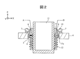
- FIG. 2 is a cross-sectional view illustrating a configuration of a part of the electron gun according to the first embodiment.
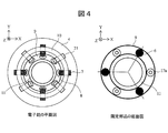
- FIG. 3 is an enlarged view of regions A and B in FIG. 2. The top view of an electron gun (left side), and the bottom view of a fixed part (right side).
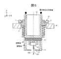
- FIG. 4 is a schematic diagram showing a method for adjusting the optical axis of an electron beam.
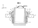
- FIG. 7 is a schematic diagram showing a tilt of a cylinder generated when a fixed component moves in a conventional electron gun. The schematic diagram showing the contact state of a support component and a flange.
- FIG. 1 is a cross-sectional view illustrating the overall configuration of the electron gun according to the first embodiment.
- FIG. 2 is a cross-sectional view illustrating a configuration of a part of the electron gun according to the first embodiment.
- FIG. 3 is an enlarged view of regions A and
- FIG. 9 is a cross-sectional view illustrating a configuration of a part of the electron gun according to the second embodiment.
- AA sectional drawing of FIG. 9 is a cross-sectional view illustrating a configuration of a part of an electron gun according to a third embodiment.
- the XY direction is a horizontal direction
- the Z direction is a vertical direction.
- the position, size, shape, range, etc. of each component shown in the drawings are shown for easy understanding of the invention, and may not represent the actual position, size, shape, range, etc. is there. Therefore, the charged particle beam device according to the present disclosure is not necessarily limited to the position, size, shape, range, and the like disclosed in the drawings and the like. Components described in the singular herein include the plural unless specifically stated otherwise.
- a charged particle beam device according to a first embodiment will be described with reference to FIGS.
- a scanning electron microscope (SEM) provided with an electron gun equipped with a field emission type electron source among charged particle beam devices will be described as an example.
- FIG. 1 is a cross-sectional view illustrating an overall configuration of an electron gun 1 according to the present embodiment.
- the electron gun 1 (charged particle gun) includes an electron gun container 3 (casing), a flange portion 4, a push-in component 7, a fixed component 9, a pedestal 10, a tube 11, a bellows 12, an insulator 13, an extraction electrode 14, and an electron source. 15 (charged particle source).
- the electron gun case 3 is a housing that houses a part of the cylinder 11, the bellows 12, the insulator 13, the extraction electrode 14, and the electron source 15.
- the electron gun case 3 has an opening 31 for inserting the tube 11 on the upper surface.
- the electron gun container 3 has a throttle hole 32 on the bottom surface through which an electron beam from the needle electrode 151 of the electron source 15 can pass.
- the throttle hole 32 is located on the central axis 100 of the charged particle beam device.
- the flange portion 4 is disposed on the electron gun container 3 and is formed in a cylindrical shape having an opening 41 having substantially the same diameter as the opening 31.
- the flange portion 4 includes a flange 5 (supporting portion) protruding into the opening 41.
- the inner diameter of the flange 5 is larger than the outer diameter of the cylinder 11 and is formed so that the flange 5 does not contact the side surface of the cylinder 11.
- the cylinder 11 is connected to the flange 5 by a bellows 12 having a bellows shape which can be extended and contracted, and is configured to be movable in a horizontal direction and a vertical direction while maintaining an internal vacuum.
- a wire connected to the extraction electrode 14 and the needle electrode 151 is accommodated inside the cylinder 11.
- the extraction electrode 14 and the electron source 15 are fixed to the bottom of the cylinder 11 via the insulator 13.
- the electron source 15 includes a needle electrode 151, a filament (not shown), a current introduction terminal, a filament insulator, a suppressor electrode, and the like.
- the electron gun 1 is configured such that an electron beam is generated from the needle-shaped electrode 151 when a high voltage is applied to the needle-shaped electrode 151 and the extraction electrode 14 from the wiring inside the cylinder 11.
- the extraction electrode 14 and the electron source 15 are insulated from the cylinder 11 by the insulator 13 in the electron gun container 3.
- the insulator 13 is provided to prevent electricity from being supplied to the electron source 15 from other than the wiring in the cylinder 11.
- the pedestal 10 is a ring-shaped component provided on the flange portion 4, and has a screw hole for inserting the push-in component 7 and a damping component 21 described later.
- the push-in component 7 has a screw groove, and is configured to be movable in the screw hole of the pedestal 10 by the rotation thereof.
- the push-in component 7 is arranged so as to be inclined downward toward the fixed component 9 with respect to the horizontal plane. By pushing the pushing component 7 against the fixed component 9, the cylinder 11 is moved vertically downward and horizontally. The movement amount of the cylinder 11 is adjusted by adjusting the protrusion amount of the push-in component 7.
- the fixed component 9 is a hollow truncated cone-shaped component fitted to the cylinder 11 and is configured to be able to move up and down by rotation.
- the cylinder 11 has a thread groove on the side surface
- the fixed component 9 has a thread groove on the inner surface.
- the fixed component 9 includes a receiver 8 at a location where the pressed component 7 comes into contact.
- the material of the fixed component 9 is a metal material such as stainless steel, for example.
- the material of the receiver 8 is a metal material having higher rigidity than the fixed component 9, such as a cemented carbide or tungsten.
- the fixed component 9 includes a support component 6 (first support component) and a buffer component 17a (second support component) on the bottom surface, and the support component 6 and the buffer component 17a come into contact with the flange 5.
- the cylinder 11 is supported.
- the electron gun 1 is arranged on the chamber 2.
- the chamber 2 includes a deflection unit 16 inside.
- the deflecting means 16 electromagnetically deflects the electron beam that has passed through the aperture 32 and enters the chamber 2 using a principle such as electrostatic deflection or electromagnetic deflection.
- the deflection unit 16 scans the sample with the electron beam by deflecting the electron beam. Further, the optical axis 105 of the electron beam may be shifted from the center axis 100 of the charged particle beam device due to the vibration of the cylinder 11, so that the deflection unit 16 corrects the shift of the optical axis 105.
- the charged particle beam apparatus includes a lens for focusing an electron beam, an objective lens, a sample chamber, a sample stage, an electron beam detector, in addition to the electron gun 1 described above.
- a charged particle beam device Such as a charged particle beam device.
- FIG. 2 is a cross-sectional view showing a part of the configuration of the electron gun 1 according to the first embodiment.
- FIG. 3 is an enlarged view of regions A and B in FIG. For simplicity of illustration, in FIG. 2, illustration of components located below the cylinder 11 and the electron gun container 3 is omitted.
- the fixing component 9 according to the present embodiment includes a support component 6 and a buffer component 17a on the bottom surface.
- ⁇ A and B in FIGS. 2 and 3 show the support component 6 and the region B shows the cushioning component 17a.
- the support component 6 is disposed on the bottom surface of the fixed component 9.
- the support component 6 is formed in a disk shape, and has a curved surface whose bottom surface is convex downward in the vertical direction. Note that the bottom surface of the support component 6 only needs to have a curved surface, and the shape is not limited to the illustrated one.
- the cylinder 11 can be supported by the support component 6 being in contact with the flange 5.
- a charged particle beam device is subjected to a heating process called baking to keep the inside of the device at a high vacuum.
- Baking is a process of heating the electron gun 1 and the like to remove gas adsorbed on the surface. Therefore, the support component 6 is made of a material that can withstand a baking temperature of 100 ° C. or more, for example.
- the material of the support component 6 is, for example, an arbitrary metal material or a resin material having high heat resistance.
- the cushioning component 17a is composed of a spring 18 (compression-deformed component), a ball 19 (contact component), and a cylindrical component 20 (hollow component).
- the cylindrical component 20 is a cylindrical component having an upper surface, and the upper portion is fitted to the bottom surface of the fixed component 9.
- the fixed component 9 has a concave portion on the bottom surface in which the cylindrical component 20 can be fitted.
- the upper surface of the cylindrical component 20 may be an opening, and the opening may be closed by the fixed component 9.
- the bottom surface of the cylindrical component 20 is an opening.
- the spring 18 has one end connected to the upper surface inside the cylindrical component 20 and the other end connected to the ball 19.
- the diameter of the cylindrical part 20 may be slightly larger than the diameter of the sphere 19 so that the sphere 19 can move up and down. If the diameter of the cylindrical part 20 is too large than the diameter of the sphere 19, the sphere 19 tends to move in the horizontal direction inside the cylindrical part 20, and it may be difficult to reduce the vibration of the cylinder 11.
- the contact component that contacts the flange 5 is not limited to the sphere 19, and may be an arbitrary shape such as an ellipsoid, a rectangular parallelepiped, or a cube.
- the rigidity of the spring 18 may be any rigidity that can be deformed when the ball 19 comes into contact with the flange 5, but is lower than the rigidity of the support component 6.
- the material of the spring 18 is, for example, a metal material lower than the rigidity of the support component 6, a resin material, or the like.
- the shape of the spring 18 is not limited to the coil spring shown in FIG. 3, but may be any shape as long as it can be compressed and deformed in the vertical direction.
- the materials of the sphere 19 and the cylindrical component 20 may be the same as those of the fixed component 9, the support component 6, or the spring 18, or may be a different metal material or resin material.
- the spring 18, the ball 19, and the cylindrical component 20 are made of a resin material, it is preferable that the resin material be able to withstand a baking temperature of 100 ° C. or more, for example.
- FIG. 4 is a plan view of the electron gun 1 (left side) and a bottom view of the fixed component 9 (right side).
- the support components 6 are arranged at three locations on the bottom surface of the fixed component 9 substantially evenly along the circumferential direction.
- the cushioning components 17 a are arranged at three locations on the bottom surface of the fixed component 9 substantially evenly along the circumferential direction, and are alternately arranged with the support components 6.
- the push-in parts 7 are arranged at substantially four positions along the circumferential direction of the pedestal 10.
- the tip of the push-in component 7 is a curved surface, and this tip is pressed against the receiver 8 of the fixed component 9. Since the push-in component 7 is arranged so as to be inclined downward toward the fixed component 9 with respect to the horizontal plane, the push-in component 7 is pressed to move the fixed component 9 in the horizontal direction and to move downward. be able to.
- the material of the push-in component 7 is, for example, any metal material, resin material, or the like.
- the electron gun 1 includes an attenuation component 21 that attenuates the vibration energy of the cylinder 11.
- the damping parts 21 are arranged at substantially four locations along the circumferential direction of the pedestal 10, and are alternately arranged with the pushing parts 7.
- the tip of the damping component 21 is a curved surface like the pushing component 7, and the tip is pressed against the receiver 8 of the fixed component 9.
- the material of the damping component 21 may be any material having a higher damping property than the support component 6, and is, for example, a metal material, a resin material, or a rubber material having a high damping property.
- the electron gun 1 is assembled as follows. First, the user moves the fixed component 9 fitted to the tube 11 downward while rotating it. At this time, the pushing part 7 is retracted outside. When the buffer component 17a provided on the bottom surface of the fixed component 9 contacts the flange 5, the user stops moving the fixed component 9. Then, the user moves the push-in component 7 toward the fixed component 9 and presses the push-in component 7 against the receiver 8 to move the tube 11 downward. When the supporting part 6 comes into contact with the flange 5, the user stops the movement of the pushing part 7, and finally moves the damping part 21 toward the fixed part 9 and presses the receiving part 8. After assembling the electron gun 1 in this manner, the optical axis 105 is adjusted by, for example, the following method.
- FIG. 5 is a schematic diagram showing a method for adjusting the optical axis 105 of the electron beam.
- the optical axis 105 is shifted from the central axis 100 or does not pass through the aperture 32 depending on the position of the needle electrode 151.
- the electron source 15 is moved in parallel with the cylinder 11 in the horizontal direction so that the optical axis 105 passes through the aperture hole 32.
- Adjust the position the electron beam is deflected by the deflecting means 16 so that the optical axis 105 is aligned with the central axis 100.
- FIG. 6 is a schematic view showing the inclination of the cylinder 11 generated when the fixed component of the conventional electron gun moves.
- the conventional electron gun includes only a disk-shaped support component 61 on the bottom surface of the fixed component 9 and does not have the buffer component 17a.
- the cylinder 11 is only supported at its lower end by the bellows 12 before the support component 61 and the flange 5 come into contact with each other while the fixed component 9 is moved downward while rotating. is there. Therefore, when the downward movement of the fixed component 9 is stopped and the pushing component 7 is pressed against the fixed component 9, the cylinder 11 is inclined as shown in FIG. 6. As a result, a bias occurs in the contact state between the three supporting components 61 and the flange 5.
- the cylinder 11 can be supported by the cushioning component 17a by the cushioning component 17a contacting before the support component 6 contacts the flange 5; , The cylinder 11 is less likely to tilt. Further, the height at which the fixed component 9 is installed in the cylinder 11 becomes constant by setting the position where the buffer component 17a and the flange 5 are in contact with each other as a reference for the vertical position of the fixed component 9 during assembly. This makes it difficult to cause variations in the tilting state due to variations in the position of the fixed component 9 in the manufacturing process of the electron gun 1 and unevenness in the contact state between the support component 6 and the flange 5.
- FIG. 7 is a schematic view showing a contact state between the support component 6 or 61 and the flange 5.
- the upper part of FIG. 7 is an enlarged view of the area A shown in FIG. 2, and the lower part is a bottom view of the support components 6 and 61.
- the disk-shaped support component 61 has a flat bottom surface.
- the contact portion with the flange 5 is dispersed on the edge of the bottom surface of the support component 61 as shown in the lower left of FIG.
- the bottom surface of the support component 6 is a curved surface as in the present embodiment, even if the support component 6 is inclined, as shown in the lower right of FIG. I do. Accordingly, the contact state is stabilized, and the rigidity for supporting the cylinder 11 and the vibration damping property of the cylinder 11 are less likely to vary.
- the electron gun 1 has the support component 6 and the cushioning component having lower rigidity than the support component 6 and contacting the flange 5 before the support component 6 on the bottom surface of the fixed component 9. 17a and a damping component 21.
- image fluctuation can be reduced by reducing vibration of the electron source 15 due to disturbance.
- the variation in the position of the fixed component 9 and the bias in the contact state between the support component 6 and the flange 5 can be suppressed, and the difference in vibration resistance performance of the charged particle beam device is reduced.
- FIG. 8 is a cross-sectional view illustrating a configuration of a part of the electron gun according to the second embodiment.
- the shock-absorbing part 17 b of the electron gun according to the second embodiment is attached to the tip of a detachable screw 22.
- a screw hole 42 for inserting the detachable screw 22 in the horizontal direction is provided on a side surface of the flange portion 4.
- the screw hole 42 is provided at a position where the buffer component 17b is arranged on the flange 5.
- the cushioning component 17b is arranged on the flange 5.
- the cushioning component 17b according to the present embodiment is configured to be detachable by inserting and removing the detachable screw 22.
- the cushioning component 17b is formed, for example, in a plate shape, and the thickness of the cushioning component 17b is larger than the thickness of the support component 6.
- the attachment / detachment screw 22 and the buffer component 17b are inserted into the screw holes 42 before the fixed component 9 is fitted to the cylinder 11, and the buffer component 17b is placed on the flange 5 in advance. Thereby, when the fixed component 9 is fitted into the cylinder 11 and moved downward, the bottom surface of the fixed component 9 contacts the buffer component 17b before the support component 6 contacts the flange 5.
- the buffer component 17b can be removed from the electron gun 1 during baking, a resin material or a rubber material having low heat resistance can be used as the material of the buffer component 17b. Further, the cushioning component 17b has such a rigidity that compression deformation is possible so that the support component 6 can be brought into contact with the flange 5 when the fixed component 9 is moved downward by pushing the pushing component 7. The rigidity of the cushioning component 17b is lower than the rigidity of the support component 6.
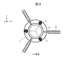
- FIG. 9 is a cross-sectional view taken along the line AA of FIG.
- the cushioning components 17 b are arranged on the bottom surface of the fixed component 9, for example, at substantially three places along the circumferential direction.
- the number of buffer components 17b is not limited to three, and any number of buffer components 17b can be arranged. From the viewpoint of suppressing the inclination and the vibration of the cylinder 11, it is preferable that the number of the buffer components 17b is two or more.
- the electron gun according to the present embodiment has a configuration in which the plate-shaped buffering component 17b, which is thicker than the support component 6 and has low rigidity, is arranged between the fixed component 9 and the flange 5. Thereby, the same effect as in the first embodiment can be obtained. Furthermore, compared with the first embodiment, the contact area between the shock-absorbing component 17b and the flange 5 is increased, so that moment shock stiffness is added to the shock-absorbing component 17b, and the cylinder 11 can be supported more stably. .
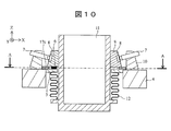
- FIG. 10 is a cross-sectional view showing a configuration of a part of the electron gun according to the third embodiment.
- the height of the flange portion 4 is equal to the height of the flange 5, and the cushioning component 17c is formed in a ring shape.
- the outer diameter of the cushioning component 17c is substantially the same as the inner diameter of the pedestal 10.
- the inner diameter of the buffer component 17c is set so that the buffer component 17c does not contact the support component 6.
- the thickness of the buffer component 17c is larger than the thickness of the support component 6.
- the cushioning component 17c is arranged on the flange 5 in advance before the fixed component 9 is fitted to the cylinder 11. Thereby, when the fixed component 9 is fitted into the cylinder 11 and moved downward, the bottom surface of the fixed component 9 contacts the cushioning component 17c before the support component 6 contacts the flange 5.
- FIG. 11 is a sectional view taken along the line AA of FIG.
- the shock-absorbing part 17c can be divided into two parts at the split 23, thereby making it easy to attach and detach.
- the cushioning component 17c may be dividable into three or more. Further, the cushioning component 17c does not need to be formed in a ring shape, and a plurality of arc-shaped cushioning components 17c may be intermittently arranged.
- the buffering component 17c can be removed by removing the base 10 and the fixing component 9 during baking. Therefore, a rubber material or the like having low heat resistance can be used as the material of the cushioning component 17c.
- the cushioning component 17c has such a rigidity that compressive deformation is possible so that the support component 6 can be brought into contact with the flange when the fixed component 9 is moved downward.
- the rigidity of the cushioning component 17c is lower than the rigidity of the support component 6.
- the electron gun according to the present embodiment has a configuration in which the ring-shaped shock-absorbing component 17c that is thicker than the support component 6 and has low rigidity is arranged between the fixed component 9 and the flange 5.
- the same effect as in the first embodiment can be obtained.
- the contact area between the buffering component 17c and the flange 5 is increased, so that moment rigidity is added to the buffering component 17c, and the cylinder 11 can be supported more stably. .
- the high damping property can be obtained by the large area of the cushioning component 17c, the vibration of the cylinder 11 can be further reduced.
- the present disclosure is not limited to the above embodiments, and includes various modifications.
- the above embodiments have been described in detail for easy understanding of the present disclosure, and are not necessarily limited to those having all the configurations described above.
- a part of the configuration of one embodiment can be replaced with the configuration of another embodiment, and the configuration of one embodiment can be added to the configuration of another embodiment.
- a scanning electron microscope has been described as an example of a charged particle beam apparatus, but a charged particle beam apparatus other than the SEM apparatus, such as a transmission electron microscope (TEM) and a focused ion beam apparatus (FIB), for example.
- TEM transmission electron microscope
- FIB focused ion beam apparatus
- the configuration according to each embodiment may be mounted.
- an electron gun having a thermoelectron emission type electron source may be employed.
- the electron gun has been described as an example, but the configuration of each embodiment can be applied to a charged particle gun such as an ion gun.
- the support component 6 is installed on the bottom surface of the fixed component 9, but may be fixed on the flange 5. Thereby, the positional relationship between the supporting component 6 and the pushing component 7 does not change.
- the bottom surface is preferably a flat surface.
- the configuration in which the support component 6 and the buffer components 17a to 17c are arranged on the flange 5 has been described.
- a configuration may be adopted in which the flange 4 and the flange 5 are not provided, and the upper surface of the electron gun case 3 is used as the support for the support component 6 and the buffer components 17a to 17c.
- the opening 31 of the electron gun case 3 into which the tube 11 is inserted is formed smaller than the outer diameter of the bottom surface of the fixed component 9.
- the bellows 12 is connected to the upper surface of the electron gun container 3.
- Electron gun 2 ... Chamber, 3 ... Electron gun container, 4 ... Flange part, 5 ... Flange, 6 ... Supporting part, 7 ... Push-in part, 8 ... Receiving, 9 ... Fixed part, 10 ... Pedestal, 11 ... Tube , 12 ... Bellows, 13 ... Insulator, 14 ... Extraction electrode, 15 ... Electron source, 16 ... Deflection means, 17a-17c ... Buffering parts, 18 ... Spring, 19 ... Ball, 20 ... Cylindrical parts, 21 ... Damping parts, 22: detachable screw, 23: split, 31: opening, 32: aperture hole, 41: opening, 42: screw hole, 100: central axis, 105: optical axis
Landscapes
- Chemical & Material Sciences (AREA)
- Analytical Chemistry (AREA)
- Electron Sources, Ion Sources (AREA)
Abstract
電子源の振動を低減し、且つ、耐振動性能に関する機差が少ない荷電粒子銃及び荷電粒子線装置を提供する。 本開示の荷電粒子銃は、荷電粒子線を発する荷電粒子源と、前記荷電粒子源が固定される筒と、前記筒に嵌合され、鉛直方向に移動可能な固定部品と、前記筒を挿入可能な開口と、前記固定部品を支持する支持部と、を有する筐体と、前記固定部品と前記支持部との間に配置される第1の支持部品及び第2の支持部品と、前記固定部品に押し当てられることにより前記筒を下方に移動させる押し込み部品と、を備え、前記第2の支持部品は、鉛直方向に圧縮変形し、前記第1の支持部品より鉛直方向の長さが大きいことを特徴とする。
Description
本開示は、荷電粒子銃及び荷電粒子線装置に関する。
荷電粒子線装置に床振動や環境音などの外乱が作用すると、装置全体が振動し、電子源と共に荷電粒子線の集束位置が振動する。荷電粒子線の集束位置が振動すると、荷電粒子線の走査領域と試料との相対的な位置関係が変位するため、像ゆれが生じる。
荷電粒子線装置の振動を低減させる技術として、特許文献1には、「床の上に架台を介して荷電粒子ビーム装置本体が配置されている荷電粒子ビーム装置において、架台の反操作側近くに、該架台に取り外し可能に取り付けられる補強部材が、前記架台の両側面より外側に延びる様に取り付けられる様に成し、荷電粒子ビーム装置本体上部と各補強部材の間に、張り出し部材が懸架出来るように成し、少なくとも架台の操作側近くの底面部に2カ所、及び、前記補強部材の張り出し部との取り付け部近くの底面部にそれぞれ除振マウントを設けるようにした荷電粒子ビーム装置」が開示されている(請求項1参照)。
また、特許文献2には、電子線の光軸ずれを抑制した電子銃として、「針状電極を有する電界放射型電子源または熱電界放射型電子源と、前記針状電極に強電界を印加して電子線を発生させるための引出電極とを備えた電子銃において、前記引出電極の固定位置を変えることにより前記針状電極と前記引出電極の偏心量を任意に設定する機能を有する」ことが開示されている(請求項1参照)。
しかしながら、特許文献1に記載の荷電粒子線装置は、電子源を内蔵する鏡筒の外側のみを支持する構造であるため、鏡筒内部の電子源は振動してしまい、像ゆれを低減することが難しい。
また、特許文献2に記載の電子銃において、引出電極は、光軸補正ねじによって引出電極ベースに支持されており、水平方向に移動可能になっている(段落0017参照)。そのため、床振動や環境音などの外乱によって光軸補正ねじが変形するため、電子源が鏡筒と独立して振動してしまう。また、光軸の調整は光軸補正ねじの押し込みによって行われているため、光軸補正ねじの押し込みの度合いにより、光軸補正ねじにより引出電極を支持するための剛性や減衰性にばらつきが生じる。この剛性や減衰性のばらつきは、荷電粒子線装置の耐振動性能の機差の原因となるため、再組立や再調整が必要になる。
以上のことから、本開示は、電子源の振動を低減し、且つ、耐振動性能に関する機差が少ない荷電粒子銃及び荷電粒子線装置を提供する。
本開示の荷電粒子銃は、荷電粒子線を発する荷電粒子源と、前記荷電粒子源が固定される筒と、前記筒に嵌合され、鉛直方向に移動可能な固定部品と、前記筒を挿入可能な開口と、前記固定部品を支持する支持部と、を有する筐体と、前記固定部品と前記支持部との間に配置される第1の支持部品及び第2の支持部品と、前記固定部品に押し当てられることにより前記筒を下方に移動させる押し込み部品と、を備え、前記第2の支持部品は、鉛直方向に圧縮変形し、前記第1の支持部品より鉛直方向の長さが大きいことを特徴とする。
本開示に関連する更なる特徴は、本明細書の記述、添付図面から明らかになるものである。また、本開示の態様は、要素及び多様な要素の組み合わせ及び以降の詳細な記述と添付される特許請求の範囲の様態により達成され実現される。
本明細書の記述は典型的な例示に過ぎず、本開示の特許請求の範囲又は適用例を如何なる意味に於いても限定するものではないことを理解する必要がある。
本明細書の記述は典型的な例示に過ぎず、本開示の特許請求の範囲又は適用例を如何なる意味に於いても限定するものではないことを理解する必要がある。
本開示によれば、電子源の振動を低減し、且つ、耐振動性能に関する機差が少ない荷電粒子銃及び荷電粒子線装置を提供することができる。
上記した以外の課題、構成及び効果は、以下の実施形態の説明により明らかにされる。
上記した以外の課題、構成及び効果は、以下の実施形態の説明により明らかにされる。
以下、実施形態について図面を用いて説明する。図面において、XY方向を水平方向とし、Z方向を鉛直方向とする。図面に示す各構成の位置、大きさ、形状、範囲などは、発明の理解を容易にするために表されたものであり、実際の位置、大きさ、形状、範囲などを表していない場合がある。このため、本開示の荷電粒子線装置は、必ずしも図面等に開示された位置、大きさ、形状、範囲などに限定されない。
本明細書において単数形で表される構成要素は、特段文脈で明らかに示されない限り、複数形を含むものとする。
本明細書において単数形で表される構成要素は、特段文脈で明らかに示されない限り、複数形を含むものとする。
[第1の実施形態]
第1の実施形態に係る荷電粒子線装置について、図1~4を参照して説明する。本実施形態においては、荷電粒子線装置のうち、電界放射型の電子源を搭載した電子銃を備える走査型電子顕微鏡(SEM)を例として説明する。
第1の実施形態に係る荷電粒子線装置について、図1~4を参照して説明する。本実施形態においては、荷電粒子線装置のうち、電界放射型の電子源を搭載した電子銃を備える走査型電子顕微鏡(SEM)を例として説明する。
<電子銃の構成例>
図1は、本実施形態に係る電子銃1の全体構成を示す断面図である。電子銃1(荷電粒子銃)は、電子銃容器3(筐体)、フランジ部4、押し込み部品7、固定部品9、台座10、筒11、ベローズ12、絶縁碍子13、引出電極14及び電子源15(荷電粒子源)を備える。
図1は、本実施形態に係る電子銃1の全体構成を示す断面図である。電子銃1(荷電粒子銃)は、電子銃容器3(筐体)、フランジ部4、押し込み部品7、固定部品9、台座10、筒11、ベローズ12、絶縁碍子13、引出電極14及び電子源15(荷電粒子源)を備える。
電子銃容器3は、筒11の一部、ベローズ12、絶縁碍子13、引出電極14及び電子源15を収容する筐体である。電子銃容器3は、筒11を挿入するための開口31を上面に有する。電子銃容器3は、電子源15の針状電極151からの電子線が通過可能な絞り穴32を底面に有する。絞り穴32は、荷電粒子線装置の中心軸100上に位置する。
フランジ部4は、電子銃容器3上に配置され、開口31と略同一の径の開口41を有する円筒状に形成される。フランジ部4は、開口41の内部に突出するフランジ5(支持部)を備える。フランジ5の内径は、筒11の外径より大きく、フランジ5が筒11の側面に接しないように形成される。
筒11は、伸縮可能な蛇腹状のベローズ12によりフランジ5と連結され、内部の真空を維持したまま水平方向及び鉛直方向に移動可能に構成される。図示は省略しているが、筒11の内部には、引出電極14及び針状電極151に接続される配線が収容される。
引出電極14及び電子源15は、絶縁碍子13を介して筒11の底面に固定される。電子源15は、針状電極151、図示しないフィラメント、電流導入端子、フィラメント碍子、サプレッサー電極等を備える。電子銃1は、筒11内部の配線から針状電極151及び引出電極14に高電圧が印加されることで、針状電極151から電子線が発生するよう構成される。
引出電極14及び電子源15は、電子銃容器3内において、絶縁碍子13により筒11と絶縁されている。絶縁碍子13は、筒11内の配線以外から電子源15に電気が供給されることを防ぐために設けられる。
台座10は、フランジ部4上に設けられるリング状の部品であり、押し込み部品7及び後述する減衰部品21を挿入するためのねじ穴を有する。押し込み部品7は、ねじ溝を有し、その回転により台座10のねじ穴内を移動可能に構成される。押し込み部品7は、水平面に対し、固定部品9に向かって下方に傾斜するように配置されている。押し込み部品7を固定部品9に押し当てることで、筒11を鉛直方向下方及び水平方向に移動させる。筒11の移動量は、押し込み部品7の突出量を調整することで調整される。
固定部品9は、筒11に嵌合される中空円錐台状の部品であり、その回転により昇降移動可能に構成される。図示は省略しているが、筒11は、側面にねじ溝が設けられ、固定部品9は、内面にねじ溝が設けられる。固定部品9は、押し込み部品7が接触する箇所に受け8を備える。固定部品9の材料は、例えばステンレス鋼などの金属材料である。受け8の材料は、例えば超硬合金やタングステンなど、固定部品9より剛性の高い金属材料である。
後述するように、固定部品9は、底面に支持部品6(第1の支持部品)及び緩衝部品17a(第2の支持部品)を備え、支持部品6及び緩衝部品17aがフランジ5と接触することで、筒11が支持される。
電子銃1は、チャンバ2上に配置される。チャンバ2は、内部に偏向手段16を備える。偏向手段16は、絞り穴32を通過してチャンバ2内に侵入した電子線を静電偏向又は電磁偏向等の原理を用いて電磁気的に偏向する。偏向手段16は、電子線を偏向させることで、試料に電子線を走査させる。また、電子線の光軸105は、筒11の振動によって荷電粒子線装置の中心軸100からずれることがあるため、偏向手段16により光軸105のずれを補正する。
なお、本実施形態に係る荷電粒子線装置の電子銃1の構成要素はこの限りではない。また、図示は省略しているが、本実施形態に係る荷電粒子線装置は、上述の電子銃1の他に、電子線を集束するレンズ、対物レンズ、試料室、試料ステージ、電子線検出器など、荷電粒子線装置に必要な構成を備える。
図2~4を参照して、本実施形態に係る電子銃1の固定部品9について詳細に説明する。図2は、第1の実施形態に係る電子銃1の一部の構成を示す断面図である。図3は、図2における領域A及びBの拡大図である。図示の簡略化のため、図2において、筒11より下方に位置する構成要素及び電子銃容器3の図示を省略している。図2及び3に示すように、本実施形態に係る固定部品9は、底面に支持部品6及び緩衝部品17aを備える。
図2及び3における領域Aは支持部品6を示し、領域Bは緩衝部品17aを示す。図3の領域Aの拡大図に示すように、支持部品6は、固定部品9の底面に配置される。支持部品6は、円盤状に形成され、底面が鉛直方向下方に凸の曲面形状を有する。なお、支持部品6の底面は曲面を持つ構造であればよく、形状は図示するものに限定されない。支持部品6がフランジ5に接触することにより、筒11を支持することができる。
一般に、荷電粒子線装置は、内部を高真空に保つため、ベーキングと呼ばれる加熱処理が行われる。ベーキングは、電子銃1などを加熱して表面に吸着したガスを脱ガスする処理である。従って、支持部品6は、例えば100℃以上のベーキング温度に耐えうる材料で構成される。支持部品6の材料は、例えば任意の金属材料や、耐熱性の高い樹脂材料等である。
図3の領域Bの拡大図に示すように、緩衝部品17aは、ばね18(圧縮変形部品)、球19(接触部品)及び円筒部品20(中空部品)から構成される。円筒部品20は、上面を有する円筒状の部品であり、上部が固定部品9の底面に嵌合されている。換言すれば、固定部品9は、円筒部品20を嵌合可能な凹部を底面に備える。なお、円筒部品20の上面は開口となっていてもよく、該開口が固定部品9により塞がれる構成であってもよい。また、円筒部品20の底面は、開口となっている。
ばね18は、円筒部品20内部の上面に一端が接続され、球19に他端が接続される。円筒部品20の直径は、球19が内部を昇降可能なように、球19の直径よりわずかに大きければよい。円筒部品20の直径が球19の直径より大きすぎると、円筒部品20の内部で球19が水平方向にも移動しやすくなり、筒11の振動を低減しにくくなる虞がある。
図示は省略しているが、ばね18が自然長であるとき、すなわち球19がフランジ5に接触していないとき、球19の最下点は、円筒部品20の開口(底面)よりも下方に位置し、且つ支持部品6の最下点よりも下方に位置する。換言すれば、緩衝部品17aは、鉛直方向の長さが支持部品6よりも大きい。このような構成により、固定部品9を筒11に嵌合して下方に移動させる際に、支持部品6よりも先に緩衝部品17aの球19がフランジ5と接触する。球19がフランジ5と接触すると、ばね18が変形し、球19が円筒部品20内部に押し込まれる。なお、フランジ5に接触する接触部品は、球19に限定されず、楕円体や直方体、立方体など、任意の形状とすることができる。
ばね18の剛性は、球19がフランジ5と接触した際に変形できる剛性であればよいが、支持部品6の剛性より低い。ばね18の材料は、例えば支持部品6の剛性よりも低い金属材料や、樹脂材料等である。ばね18の形状は、図3に示すコイルばねに限定されず、鉛直方向に圧縮変形可能であれば任意の形状を採用できる。
球19及び円筒部品20の材料は、固定部品9、支持部品6又はばね18と同様であってもよいし、これらと異なる金属材料や樹脂材料であってもよい。ばね18、球19及び円筒部品20が樹脂材料である場合、例えば100℃以上のベーキング温度に耐えうる樹脂材料であることが好ましい。
図4は、電子銃1の平面図(左側)及び固定部品9の底面図(右側)である。図4の底面図に示すように、支持部品6は、固定部品9の底面において、周方向に沿ってほぼ均等に3箇所配置される。また、緩衝部品17aは、固定部品9の底面において、周方向に沿ってほぼ均等に3箇所配置されており、支持部品6と交互に配置される。
図4の平面図に示すように、押し込み部品7は、台座10の周方向に沿ってほぼ均等に4箇所配置されている。押し込み部品7の先端は曲面であり、この先端が固定部品9の受け8に押し当てられる。押し込み部品7は、水平面に対し、固定部品9に向かって下方に傾斜するように配置されているため、押し込み部品7を押し当てることにより固定部品9を水平方向へ移動させつつ、下方へ移動させることができる。押し込み部品7の材料は、例えば任意の金属材料、樹脂材料等である。
図4の平面図に示すように、本実施形態に係る電子銃1は、筒11の振動エネルギを減衰させる減衰部品21を備える。減衰部品21が固定部品9に接触することにより減衰性が付加され、筒11の振動を抑制することができる。減衰部品21は、台座10の周方向に沿ってほぼ均等に4箇所配置されており、押し込み部品7と交互に配置されている。減衰部品21は、押し込み部品7と同様に先端が曲面であり、この先端が固定部品9の受け8に押し当てられる。減衰部品21の材料は、支持部品6よりも減衰性の高い材料であればよく、例えば高減衰性の金属材料や樹脂材料、ゴム材料等である。
本実施形態に係る電子銃1は、次のように組み立てられる。まず、ユーザーは、筒11に嵌合された固定部品9を回転させながら下方へ移動させる。このとき、押し込み部品7は外側に退避されている。固定部品9の底面に設けられた緩衝部品17aとフランジ5とが接触したら、ユーザーは、固定部品9の移動を止める。そして、ユーザーは、押し込み部品7を固定部品9に向かって移動させ、受け8に押し当てることで、筒11を下方へと移動させる。支持部品6がフランジ5と接触したら、ユーザーは、押し込み部品7の移動を止め、最後に、減衰部品21を固定部品9に向かって移動させ、受け8に押し当てる。このようにして電子銃1を組み立てた後、例えば以下の方法により、光軸105を調整する。
図5は、電子線の光軸105の調整方法を示す概略図である。上記のように電子銃1を組み立てた後、針状電極151の位置によっては、光軸105が中心軸100からずれていたり、絞り穴32を通過しなかったりしてしまう。この場合、図5に示すように、押し込み部品7を固定部品9に押し当てることにより、筒11と共に電子源15を水平方向に平行移動させて、光軸105が絞り穴32を通過するように、位置を調整する。そして、偏向手段16により電子線を偏向させ、中心軸100に光軸105を合わせる。
図6は、従来の電子銃における固定部品の移動時に生じる筒11の傾きを示す概略図である。図6に示すように、従来の電子銃は、固定部品9の底面に、円盤状の支持部品61のみを備え、緩衝部品17aを有しない。このような従来の電子銃において、固定部品9を回転させながら下方へ移動させる間、支持部品61とフランジ5が接触する前は、筒11は、下端部をベローズ12によって支持されているのみである。従って、固定部品9の下方への移動を止めた後、固定部品9に押し込み部品7を押し当てると、図6に示すように筒11が傾斜する。これにより、3箇所ある支持部品61とフランジ5との接触状態に偏りが生じる。また、固定部品9の鉛直方向の位置は組立者に依存するため、製造過程におけるばらつきが生じ、これにより筒11の傾斜状態にもばらつきが生じる。このような支持部品61及びフランジ5の接触状態の偏りや、筒11の傾斜状態のばらつきは、筒11を支持するための剛性や、筒11の振動の減衰性にばらつきが生じる要因となる。
一方、本実施形態のように、支持部品6がフランジ5に接触する前に緩衝部品17aが接触することによって、緩衝部品17aにより筒11を支持することができるため、押し込み部品7を固定部品9に押し当てても筒11が傾斜しにくくなる。また、組み立て時における固定部品9の鉛直方向の位置の基準として、緩衝部品17aとフランジ5とが接触する位置とすることによって、固定部品9が筒11に設置される高さが一定になる。これにより、電子銃1の製造過程における固定部品9の位置のばらつきによる傾斜状態のばらつきや、支持部品6及びフランジ5の接触状態の偏りが生じにくくなる。
図7は、支持部品6又は61と、フランジ5との接触状態を示す概略図である。図7の上段は、図2に示す領域Aの拡大図であり、下段は支持部品6及び61の底面図である。図7に示すように、円盤状の支持部品61は、底面が平面である。この場合、支持部品61が傾斜した際に、フランジ5との接触箇所は、図7の左下に示すように、支持部品61の底面の縁に分散する。一方、本実施形態のように、支持部品6の底面が曲面である場合は、支持部品6が傾斜しても、図7の右下に示すように、フランジ5との接触箇所が一点に集中する。これにより、接触状態が安定し、筒11を支持するための剛性や、筒11の振動の減衰性にばらつきがより生じにくくなる。
<技術的効果>
以上のように、本実施形態に係る電子銃1は、固定部品9の底面に、支持部品6と、支持部品6よりも剛性が低く、支持部品6よりも先にフランジ5に接触する緩衝部品17aと、減衰部品21とを備える。このような構成により、外乱による電子源15の振動を低減させることで、像ゆれを低減させることができる。さらに、固定部品9の位置のばらつきや、支持部品6とフランジ5との接触状態の偏りを抑制することができ、荷電粒子線装置の耐振動性能に関する機差が低減される。
以上のように、本実施形態に係る電子銃1は、固定部品9の底面に、支持部品6と、支持部品6よりも剛性が低く、支持部品6よりも先にフランジ5に接触する緩衝部品17aと、減衰部品21とを備える。このような構成により、外乱による電子源15の振動を低減させることで、像ゆれを低減させることができる。さらに、固定部品9の位置のばらつきや、支持部品6とフランジ5との接触状態の偏りを抑制することができ、荷電粒子線装置の耐振動性能に関する機差が低減される。
[第2の実施形態]
第2の実施形態に係る荷電粒子線装置の電子銃について、図8及び9を参照して説明する。なお、第2の実施形態に係る電子銃は、緩衝部品及びフランジの構成以外は第1の実施形態と同様であるため、説明を省略する。
第2の実施形態に係る荷電粒子線装置の電子銃について、図8及び9を参照して説明する。なお、第2の実施形態に係る電子銃は、緩衝部品及びフランジの構成以外は第1の実施形態と同様であるため、説明を省略する。
図8は、第2の実施形態に係る電子銃の一部の構成を示す断面図である。図8に示すように、第2の実施形態に係る電子銃の緩衝部品17bは、着脱ねじ22の先端に取り付けられる。フランジ部4の側面には、着脱ねじ22を水平方向に挿入するためのねじ穴42が設けられる。ねじ穴42は、緩衝部品17bがフランジ5上に配置されるような位置に設けられる。着脱ねじ22をねじ穴42に挿入することで、緩衝部品17bは、フランジ5上に配置される。このように、本実施形態に係る緩衝部品17bは、着脱ねじ22の出し入れにより着脱可能に構成される。
緩衝部品17bは、例えば板状に形成され、緩衝部品17bの厚さは、支持部品6の厚さより大きい。着脱ねじ22及び緩衝部品17bは、固定部品9を筒11に嵌合する前にねじ穴42に挿入され、予め緩衝部品17bをフランジ5上に載置しておく。これにより、固定部品9が筒11に嵌合され下方に移動される際に、支持部品6がフランジ5に接触する前に、固定部品9の底面が緩衝部品17bに接触する。
緩衝部品17bは、ベーキング時に電子銃1から取り外すことができるため、緩衝部品17bの材料として、耐熱性が低い樹脂材料やゴム材料などを採用することができる。また、緩衝部品17bは、押し込み部品7の押し込みにより固定部品9を下方に移動させる際に、支持部品6をフランジ5に接触させることができるように、圧縮変形が可能な程度の剛性を有する。緩衝部品17bの剛性は、支持部品6の剛性よりも低い。
図9は、図8のA-A断面図である。図9に示すように、緩衝部品17bは、固定部品9の底面において、例えば周方向に沿ってほぼ均等に3箇所配置される。緩衝部品17bの数は3つに限定されず、任意の数の緩衝部品17bを配置することができる。筒11の傾斜や振動を抑制する観点から、緩衝部品17bの数は2つ以上であることが好ましい。
<技術的効果>
以上のように、本実施形態に係る電子銃は、支持部品6よりも厚く、且つ剛性の低い板状の緩衝部品17bが固定部品9とフランジ5との間に配置される構成を有する。これにより、第1の実施形態と同様の効果を奏することができる。さらに、第1の実施形態と比較して、緩衝部品17bとフランジ5との接触面積が増えるため、緩衝部品17bにモーメント剛性が付加され、筒11をより安定して支持することが可能になる。
以上のように、本実施形態に係る電子銃は、支持部品6よりも厚く、且つ剛性の低い板状の緩衝部品17bが固定部品9とフランジ5との間に配置される構成を有する。これにより、第1の実施形態と同様の効果を奏することができる。さらに、第1の実施形態と比較して、緩衝部品17bとフランジ5との接触面積が増えるため、緩衝部品17bにモーメント剛性が付加され、筒11をより安定して支持することが可能になる。
[第3の実施形態]
第3の実施形態に係る荷電粒子線装置の電子銃について、図10及び11を参照して説明する。なお、第3の実施形態に係る電子銃は、緩衝部品、フランジ及びフランジの構成以外は第1の実施形態と同様であるため、説明を省略する。
第3の実施形態に係る荷電粒子線装置の電子銃について、図10及び11を参照して説明する。なお、第3の実施形態に係る電子銃は、緩衝部品、フランジ及びフランジの構成以外は第1の実施形態と同様であるため、説明を省略する。
図10は、第3の実施形態に係る電子銃の一部の構成を示す断面図である。図10に示すように、本実施形態においては、フランジ部4とフランジ5の高さが等しく、緩衝部品17cは、リング状に構成される。緩衝部品17cの外径は、台座10の内径と略同一である。緩衝部品17cの内径は、緩衝部品17cが支持部品6と接触しないように設定される。
緩衝部品17cの厚さは、支持部品6の厚さよりも大きい。また、緩衝部品17cは、固定部品9を筒11に嵌合する前に、予めフランジ5上に配置される。これにより、固定部品9が筒11に嵌合され下方に移動される際に、支持部品6がフランジ5に接触する前に、固定部品9の底面が緩衝部品17cに接触する。
図11は、図10のA-A断面図である。図11に示すように、緩衝部品17cは、割れ目23において2つに分割することができ、これにより着脱が容易である。なお、緩衝部品17cは、3つ以上に分割可能であってもよい。また、緩衝部品17cは、リング状に形成されている必要はなく、複数の円弧状の緩衝部品17cが断続的に配置されていてもよい。
例えばベーキング時に台座10及び固定部品9を取り外すことにより、緩衝部品17cを取り外すことができる。よって、緩衝部品17cの材料として、耐熱性が低いゴム材料などを採用することができる。緩衝部品17cは、固定部品9を下方に移動させる際に、支持部品6をフランジに接触させることができるように、圧縮変形が可能な程度の剛性を有する。緩衝部品17cの剛性は、支持部品6の剛性よりも低い。
<技術的効果>
以上のように、本実施形態に係る電子銃は、支持部品6よりも厚く、且つ剛性の低いリング状の緩衝部品17cが固定部品9とフランジ5との間に配置される構成を有する。これにより、第1の実施形態と同様の効果を奏することができる。さらに、第1の実施形態と比較して、緩衝部品17cとフランジ5との接触面積が増えるため、緩衝部品17cにモーメント剛性が付加され、筒11をより安定して支持することが可能になる。また、緩衝部品17cの面積が大きいことにより高い減衰性が得られるため、筒11の振動をより低減することができる。
以上のように、本実施形態に係る電子銃は、支持部品6よりも厚く、且つ剛性の低いリング状の緩衝部品17cが固定部品9とフランジ5との間に配置される構成を有する。これにより、第1の実施形態と同様の効果を奏することができる。さらに、第1の実施形態と比較して、緩衝部品17cとフランジ5との接触面積が増えるため、緩衝部品17cにモーメント剛性が付加され、筒11をより安定して支持することが可能になる。また、緩衝部品17cの面積が大きいことにより高い減衰性が得られるため、筒11の振動をより低減することができる。
[変形例]
本開示は上記実施形態に限定されるものではなく、様々な変形例が含まれる。例えば、上記実施形態は本開示を分かりやすく説明するために詳細に説明したものであり、必ずしも説明した全ての構成を備えるものに限定されるものではない。また、ある実施形態の構成の一部を他の実施形態の構成に置き換えることが可能であり、また、ある実施形態の構成に他の実施形態の構成を加えることも可能である。また、各実施形態の構成の一部について、他の構成の追加・削除・置換をすることが可能である。
本開示は上記実施形態に限定されるものではなく、様々な変形例が含まれる。例えば、上記実施形態は本開示を分かりやすく説明するために詳細に説明したものであり、必ずしも説明した全ての構成を備えるものに限定されるものではない。また、ある実施形態の構成の一部を他の実施形態の構成に置き換えることが可能であり、また、ある実施形態の構成に他の実施形態の構成を加えることも可能である。また、各実施形態の構成の一部について、他の構成の追加・削除・置換をすることが可能である。
上記実施形態において、荷電粒子線装置として走査型電子顕微鏡(SEM)を例に説明したが、例えば透過型電子顕微鏡(TEM)や集束イオンビーム装置(FIB)など、SEM装置以外の荷電粒子線装置に、各実施形態に係る構成を搭載してもよい。また、電子銃として熱電子放出型の電子源を有するものを採用してもよい。さらに、上記実施形態では電子銃を例に説明したが、イオン銃などの荷電粒子銃にも各実施形態の構成を適用可能である。
また、第1の実施形態において、支持部品6を固定部品9の底面に設置していたが、フランジ5上に固定してもよい。これにより、支持部品6と押し込み部品7との位置関係は変化しなくなる。なお、支持部品6をフランジ5上に設ける場合、その底面は平面であることが好ましい。
さらに、上記実施形態において、支持部品6及び緩衝部品17a~17cは、フランジ5上に配置される構成を説明した。しかし、フランジ部4及びフランジ5を設けず、電子銃容器3の上面を支持部品6及び緩衝部品17a~17cの支持部とした構成であってもよい。この場合、筒11が挿入される電子銃容器3の開口31は、固定部品9の底面における外径よりも小さく形成される。また、ベローズ12は、電子銃容器3の上面に接続される。
1…電子銃、2…チャンバ、3…電子銃容器、4…フランジ部、5…フランジ、6…支持部品、7…押し込み部品、8…受け、9…固定部品、10…台座、11…筒、12…ベローズ、13…絶縁碍子、14…引出電極、15…電子源、16…偏向手段、17a~17c…緩衝部品、18…ばね、19…球、20…円筒部品、21…減衰部品、22…着脱ねじ、23…割れ目、31…開口、32…絞り穴、41…開口、42…ねじ穴、100…中心軸、105…光軸
Claims (10)
- 荷電粒子線を発する荷電粒子源と、
前記荷電粒子源が固定される筒と、
前記筒に嵌合され、鉛直方向に移動可能な固定部品と、
前記筒を挿入可能な開口と、前記固定部品を支持する支持部と、を有する筐体と、
前記固定部品と前記支持部との間に配置される第1の支持部品及び第2の支持部品と、 前記固定部品に押し当てられることにより前記筒を下方に移動させる押し込み部品と、を備え、
前記第2の支持部品は、鉛直方向に圧縮変形し、前記第1の支持部品より鉛直方向の長さが大きいことを特徴とする荷電粒子銃。 - 前記第1の支持部品より減衰性が高く、前記固定部品に接触可能な減衰部品をさらに備えることを特徴とする請求項1記載の荷電粒子銃。
- 前記第1の支持部品の底面は、曲面構造を有することを特徴とする請求項1記載の荷電粒子銃。
- 前記第2の支持部品は、前記第1の支持部品より剛性が低いことを特徴とする請求項1記載の荷電粒子銃。
- 前記第1の支持部品及び前記第2の支持部品をそれぞれ複数備え、前記第1の支持部品及び前記第2の支持部品は、前記固定部品の底面の周方向に沿って交互に配置されることを特徴とする請求項1記載の荷電粒子銃。
- 前記押し込み部品及び前記減衰部品は、前記筐体の上部において前記開口の周方向に沿って交互に配置されることを特徴とする請求項2記載の荷電粒子銃。
- 前記第2の支持部品は、
中空部品と、
前記中空部品内部の上面に一端が接続される圧縮変形部品と、
前記圧縮変形部品の他端に接続される接触部品と、を備え、
前記圧縮変形部品は、前記第1の支持部品より剛性が低いことを特徴とする請求項1記載の荷電粒子銃。 - 前記支持部は、前記筐体上に配置され、前記開口の内部に突出するフランジを有するフランジ部を含み、
前記フランジ部は、前記第2の支持部品を挿入可能なねじ穴を側面に有し、
前記第2の支持部品は、前記ねじ穴から着脱可能な着脱ねじを有し、
前記第2の支持部品は、前記着脱ねじが前記ねじ穴に挿入された状態において前記フランジ上へ配置されることを特徴とする請求項1記載の荷電粒子銃。 - 前記第2の支持部品は、リング状又は円弧状に形成されることを特徴とする請求項1記載の荷電粒子銃。
- 請求項1に記載の荷電粒子銃を備える荷電粒子線装置。
Priority Applications (1)
| Application Number | Priority Date | Filing Date | Title |
|---|---|---|---|
| JP2020535484A JP6953635B2 (ja) | 2018-08-09 | 2018-11-27 | 荷電粒子銃及び荷電粒子線装置 |
Applications Claiming Priority (2)
| Application Number | Priority Date | Filing Date | Title |
|---|---|---|---|
| JP2018-149844 | 2018-08-09 | ||
| JP2018149844 | 2018-08-09 |
Publications (1)
| Publication Number | Publication Date |
|---|---|
| WO2020031399A1 true WO2020031399A1 (ja) | 2020-02-13 |
Family
ID=69414629
Family Applications (1)
| Application Number | Title | Priority Date | Filing Date |
|---|---|---|---|
| PCT/JP2018/043468 Ceased WO2020031399A1 (ja) | 2018-08-09 | 2018-11-27 | 荷電粒子銃及び荷電粒子線装置 |
Country Status (2)
| Country | Link |
|---|---|
| JP (1) | JP6953635B2 (ja) |
| WO (1) | WO2020031399A1 (ja) |
Cited By (3)
| Publication number | Priority date | Publication date | Assignee | Title |
|---|---|---|---|---|
| JP2021174772A (ja) * | 2020-04-24 | 2021-11-01 | アイエムエス ナノファブリケーション ゲーエムベーハー | 荷電粒子源 |
| JP7455439B1 (ja) | 2023-05-31 | 2024-03-26 | Muscatスペース・エンジニアリング株式会社 | 人工物体の制御方法、人工物体の制御装置およびこれを備えた人工物体 |
| JP7569461B1 (ja) | 2024-01-12 | 2024-10-17 | 株式会社エー・アンド・デイ | 電子銃のアライメント機構および該アライメント機構を用いた検査方法 |
Citations (1)
| Publication number | Priority date | Publication date | Assignee | Title |
|---|---|---|---|---|
| JPH1092363A (ja) * | 1996-09-19 | 1998-04-10 | Jeol Ltd | 電子線用加速管 |
-
2018
- 2018-11-27 WO PCT/JP2018/043468 patent/WO2020031399A1/ja not_active Ceased
- 2018-11-27 JP JP2020535484A patent/JP6953635B2/ja active Active
Patent Citations (1)
| Publication number | Priority date | Publication date | Assignee | Title |
|---|---|---|---|---|
| JPH1092363A (ja) * | 1996-09-19 | 1998-04-10 | Jeol Ltd | 電子線用加速管 |
Cited By (6)
| Publication number | Priority date | Publication date | Assignee | Title |
|---|---|---|---|---|
| JP2021174772A (ja) * | 2020-04-24 | 2021-11-01 | アイエムエス ナノファブリケーション ゲーエムベーハー | 荷電粒子源 |
| JP7555297B2 (ja) | 2020-04-24 | 2024-09-24 | アイエムエス ナノファブリケーション ゲーエムベーハー | 荷電粒子源 |
| JP7455439B1 (ja) | 2023-05-31 | 2024-03-26 | Muscatスペース・エンジニアリング株式会社 | 人工物体の制御方法、人工物体の制御装置およびこれを備えた人工物体 |
| WO2024247909A1 (ja) * | 2023-05-31 | 2024-12-05 | Muscatスペース・エンジニアリング株式会社 | 人工物体の制御方法、人工物体の制御装置およびこれを備えた人工物体 |
| JP7569461B1 (ja) | 2024-01-12 | 2024-10-17 | 株式会社エー・アンド・デイ | 電子銃のアライメント機構および該アライメント機構を用いた検査方法 |
| JP2025109446A (ja) * | 2024-01-12 | 2025-07-25 | 株式会社エー・アンド・デイ | 電子銃のアライメント機構および該アライメント機構を用いた検査方法 |
Also Published As
| Publication number | Publication date |
|---|---|
| JP6953635B2 (ja) | 2021-10-27 |
| JPWO2020031399A1 (ja) | 2021-08-02 |
Similar Documents
| Publication | Publication Date | Title |
|---|---|---|
| JP4918193B2 (ja) | イオン抽出アセンブリ | |
| JP6953635B2 (ja) | 荷電粒子銃及び荷電粒子線装置 | |
| US5399860A (en) | Electron optic column and scanning electron microscope | |
| JP6987233B2 (ja) | 荷電粒子線装置及びその軸調整方法 | |
| JP6267543B2 (ja) | 収差補正器及びそれを用いた荷電粒子線装置 | |
| KR20190140899A (ko) | X선관 및 x선 발생 장치 | |
| JP5734809B2 (ja) | 単純化粒子エミッタ及びその動作方法 | |
| US10096448B2 (en) | Spherical aberration corrector for electromagnetic lens for charged particle beam | |
| US11189451B2 (en) | Charged particle beam source and a method for assembling a charged particle beam source | |
| JP5504277B2 (ja) | 走査電子顕微鏡 | |
| CN111199856A (zh) | 配备有自动光束对准的电子显微镜 | |
| JP6740448B2 (ja) | 荷電粒子線装置 | |
| JP6809809B2 (ja) | 絶縁構造、荷電粒子銃及び荷電粒子線応用装置 | |
| EP0689224B1 (en) | Charged particle beam device | |
| KR0174565B1 (ko) | 기계적으로 안정한 방사총 어셈블리 | |
| US2277024A (en) | Electronic microscope | |
| JP2022127284A (ja) | 多極子ユニットおよび荷電粒子線装置 | |
| US3038094A (en) | Ruggedized electric discharge device structure | |
| KR101089231B1 (ko) | X선관 | |
| JP3723577B2 (ja) | 線状焦点電子ビームデバイスのための陰極アセンブリ | |
| TWI917910B (zh) | 帶電粒子線裝置 | |
| CN118588522B (zh) | 用于带电粒子束装置的载物单元及相关产品 | |
| WO2024201811A1 (ja) | 荷電粒子線装置 | |
| US2922153A (en) | Mounting of cathode ray tubes | |
| WO2025069287A1 (ja) | 荷電粒子線装置と電子銃 |
Legal Events
| Date | Code | Title | Description |
|---|---|---|---|
| 121 | Ep: the epo has been informed by wipo that ep was designated in this application |
Ref document number: 18929665 Country of ref document: EP Kind code of ref document: A1 |
|
| ENP | Entry into the national phase |
Ref document number: 2020535484 Country of ref document: JP Kind code of ref document: A |
|
| NENP | Non-entry into the national phase |
Ref country code: DE |
|
| 122 | Ep: pct application non-entry in european phase |
Ref document number: 18929665 Country of ref document: EP Kind code of ref document: A1 |