WO2020031356A1 - ユーザ端末、及び、無線通信方法 - Google Patents
ユーザ端末、及び、無線通信方法 Download PDFInfo
- Publication number
- WO2020031356A1 WO2020031356A1 PCT/JP2018/030000 JP2018030000W WO2020031356A1 WO 2020031356 A1 WO2020031356 A1 WO 2020031356A1 JP 2018030000 W JP2018030000 W JP 2018030000W WO 2020031356 A1 WO2020031356 A1 WO 2020031356A1
- Authority
- WO
- WIPO (PCT)
- Prior art keywords
- antennas
- information
- coherent
- base station
- user terminal
- Prior art date
Links
Images


Classifications
-
- H—ELECTRICITY
- H04—ELECTRIC COMMUNICATION TECHNIQUE
- H04B—TRANSMISSION
- H04B7/00—Radio transmission systems, i.e. using radiation field
- H04B7/02—Diversity systems; Multi-antenna system, i.e. transmission or reception using multiple antennas
- H04B7/04—Diversity systems; Multi-antenna system, i.e. transmission or reception using multiple antennas using two or more spaced independent antennas
- H04B7/06—Diversity systems; Multi-antenna system, i.e. transmission or reception using multiple antennas using two or more spaced independent antennas at the transmitting station
- H04B7/0686—Hybrid systems, i.e. switching and simultaneous transmission
-
- H—ELECTRICITY
- H04—ELECTRIC COMMUNICATION TECHNIQUE
- H04B—TRANSMISSION
- H04B7/00—Radio transmission systems, i.e. using radiation field
- H04B7/02—Diversity systems; Multi-antenna system, i.e. transmission or reception using multiple antennas
- H04B7/04—Diversity systems; Multi-antenna system, i.e. transmission or reception using multiple antennas using two or more spaced independent antennas
- H04B7/0404—Diversity systems; Multi-antenna system, i.e. transmission or reception using multiple antennas using two or more spaced independent antennas the mobile station comprising multiple antennas, e.g. to provide uplink diversity
-
- H—ELECTRICITY
- H04—ELECTRIC COMMUNICATION TECHNIQUE
- H04B—TRANSMISSION
- H04B7/00—Radio transmission systems, i.e. using radiation field
- H04B7/02—Diversity systems; Multi-antenna system, i.e. transmission or reception using multiple antennas
- H04B7/04—Diversity systems; Multi-antenna system, i.e. transmission or reception using multiple antennas using two or more spaced independent antennas
- H04B7/0413—MIMO systems
- H04B7/0456—Selection of precoding matrices or codebooks, e.g. using matrices antenna weighting
-
- H—ELECTRICITY
- H04—ELECTRIC COMMUNICATION TECHNIQUE
- H04W—WIRELESS COMMUNICATION NETWORKS
- H04W16/00—Network planning, e.g. coverage or traffic planning tools; Network deployment, e.g. resource partitioning or cells structures
- H04W16/24—Cell structures
- H04W16/28—Cell structures using beam steering
-
- H—ELECTRICITY
- H04—ELECTRIC COMMUNICATION TECHNIQUE
- H04B—TRANSMISSION
- H04B7/00—Radio transmission systems, i.e. using radiation field
- H04B7/02—Diversity systems; Multi-antenna system, i.e. transmission or reception using multiple antennas
- H04B7/10—Polarisation diversity; Directional diversity
Definitions
- the present invention relates to a user terminal and a wireless communication method.
- LTE Long Term Evolution
- FAA Future Radio Access
- 5G 5th generation mobile communication system
- 5G + 5th generation mobile communication system
- New-RAT Radio Access Technology
- NR Radio
- Non-Patent Document 1 a user terminal transmits and receives signals using two or four antennas.
- One aspect of the present disclosure is to provide a user terminal and a wireless communication method capable of appropriately sharing information on an antenna configuration between the user terminal and a base station.
- a user terminal includes a transmission unit having a plurality of antennas, and a control unit that controls a phase of a signal transmitted from the plurality of antennas to a base station, wherein the control unit is configured
- the base station performs control for notifying one of the first information and the second information to the base station, and the first information includes a plurality of arrangements that each of the antennas can take when all of the plurality of antennas are coherent.
- the second information is information indicating any one of patterns, and the second information is information indicating the number of coherent antennas when at least two of the plurality of antennas are coherent.
- information on the antenna configuration can be appropriately shared between the user terminal and the base station.
- FIG. 2 is a diagram illustrating a configuration example of a user terminal according to one embodiment. It is a figure showing an example of communication processing based on a codebook (codebook) of a base station and a user terminal concerning one embodiment.
- FIG. 5 is a diagram illustrating a coherency pattern when the user terminal according to one embodiment includes two or four antennas.
- FIG. 5 is a diagram for explaining a relationship between coherency and a codebook when a user terminal according to one embodiment has four antennas.
- FIG. 6 is a diagram illustrating an example of an antenna configuration pattern when a user terminal according to one embodiment transmits a single polarization.
- FIG. 6 is a diagram illustrating an example of an antenna configuration pattern when a user terminal according to one embodiment transmits cross polarization.
- FIG. 2 is a diagram illustrating an example of a hardware configuration of a user terminal and a base station according to one embodiment.
- the user terminal 10 includes a reference signal generation unit 101, a data generation unit 102, a beamforming unit 103, a communication unit 104, an antenna 105, and a control unit 106.
- FIG. 1 components for generating an Orthogonal Frequency Division Multiplexing (OFDM) signal in the user terminal 10 (for example, an Inverse Fast Fourier Transform (IFFT) processing unit, a Cyclic Prefix (CP) adding unit) and the like are described. Omitted. Further, the signal waveform of the signal transmitted from the user terminal 10 is not limited to a waveform based on OFDM modulation.
- OFDM Orthogonal Frequency Division Multiplexing
- IFFT Inverse Fast Fourier Transform
- CP Cyclic Prefix
- the signal waveform of the signal transmitted from the user terminal 10 is not limited to a waveform based on OFDM modulation.
- Reference signal generating section 101 generates a reference signal (Reference Signal (RS)) used for channel estimation, and outputs it to beamforming section 103.
- RS Reference Signal
- the data generation unit 102 generates a data signal for a base station. Further, the data generation unit 102 includes an encoding unit 111 and a modulation unit 112. The encoding unit 111 and the modulation unit 112 are provided corresponding to the number of streams ( Mj ) of signals to the base station. Each coding unit 111, respectively encode the data signal of M j-number of streams, each modulation unit 112 modulates each data coded signal, and outputs the data signal after modulation to the beam forming unit 103 . Note that the coding rate and / or modulation scheme in each coding unit 111 and each modulation unit 112 may be different for each stream.
- the beamforming unit 103 multiplies a data signal input from the data generation unit 102 by, for example, a precoding matrix corresponding to a codebook, and communicates a data signal ( NT signals) after Beamforming (BF). Output to the unit 104.
- the communication unit 104 is provided corresponding to each of the NT antennas 105 (antenna elements).
- the communication unit 104 performs transmission processing such as D / A (Digital / Analog) conversion and up-conversion on the input signal, multiplexes the signal after the transmission processing by, for example, time, frequency, or code, Transmission is performed from the NT antennas 105, respectively.
- communication section 104 transmits a stream signal input from beamforming section 103 to a base station via antenna 105 (that is, transmits an Uplink (UL) signal) during data transmission.
- UL Uplink
- the communication unit 104 may be called a transmission unit.
- the control unit 106 controls the data generation unit 102. Further, the control unit 106 controls the beamforming unit 103 to control the BF of the UL signal.
- the operation of the user terminal in the following description may be an operation realized by the control performed by the control unit 106.
- the user terminal 10 may be expressed as User @ Equipment (UE), and the base station may be expressed as gNodeB (gNB).
- UE User @ Equipment
- gNB gNodeB
- the UE 10 transmits a Sounding Reference Signal (SRS) to the gNB 20.
- the gNB 20 determines resource allocation of the UE 10 based on the received SRS, and notifies the UE 10 of a UL grant. Specifically, the gNB 20 notifies the UE 10 of a Scheduling Request Indicator (SRI), a Transmitted Precoding Matrix Indicator (TPMI), a Transmitted Rank Indicator (TRI), a Modulation and Coding Scheme (MCS), and the like.
- SRI Scheduling Request Indicator
- TPMI Transmitted Precoding Matrix Indicator
- TRI Transmitted Rank Indicator
- MCS Modulation and Coding Scheme
- the UE 10 transmits the BF-performed UL signal to the gNB 20 using the Physical Grant Uplink Shared Channel (PUSCH) of the UE grant.
- PUSCH Physical Grant Uplink Shared Channel
- the UE 10 performs BF based on the codebook indicated by the
- codebooks precoding matrices
- a codebook used when UE10 supports only non-coherent a codebook used when UE10 supports partial-coherent and non-coherent
- UE10 is full Codebooks used when supporting -coherent, partial-coherent, and non-coherent are specified.
- the codebook used by the UE 10 may be determined based on the capability of the UE 10 as described below. That is, the UE 10 reports information on the antenna configuration illustrated in FIG. 3 to the gNB 20 by using the UE capability in the NR standard (Release 15). The information on the reported antenna configuration indicates, for example, whether the antenna configuration is full-coherent, partial-coherent, or non-coherent.
- the gNB 20 selects a codebook used for UL transmission of the UE 10 from the codebook illustrated in FIG. 4 based on the UE capability.
- the UE 10 may report Capability information indicating that the codebooks of the full-coherent, partial-coherent, and non-coherent cases are supported.
- the UE 10 may report information of Capability indicating that the codebook of the partial-coherent and non-coherent cases is supported.
- the UE 10 may report Capability information indicating that a codebook in a non-coherent case is supported.
- the UE 10 includes two or four antennas.
- the information on the antenna configuration is only provided by the existing information to be notified to the gNB 20 in the case of four antennas. Not enough.
- the UE 10 includes a large number (for example, 5 or more) of antennas, the number of panels (antenna panels) on which the antennas are arranged, the number of antennas per panel, and the pattern such as the positional relationship between the panels are four antennas. To increase more.
- the pattern of the antenna configuration that is partial-coherent increases as compared with the case of four antennas.
- information on the antenna configuration is insufficient to report Capability information indicating partial-coherent as in the case of four antennas, and the gNB 20 uses an appropriate codebook (precoding matrix). ) Cannot be selected.
- codebook precoding matrix
- the pattern of the antenna configuration increases as compared to the case of four antennas, as illustrated in FIG. 5 or FIG.
- the antenna configuration can take a plurality of patterns for the following (A1), (A2), and (A3).
- (A1) Pattern related to coherency and / or panel configuration In the case of four antennas, as shown in FIG. 3, the pattern of the partial-coherent is one pattern. On the other hand, in the case of eight antennas, as illustrated in FIGS. 5B and 5C or FIGS. 6B and 6C, two or more partial-coherent patterns are used. Can be taken. That is, in the case of eight antennas, the number of possible variations of the panel configuration is larger than that in the case of four antennas, so that the pattern of the partial-coherent increases.
- A2 Pattern of Antenna Array Up to four antennas, if one cross-polarized wave is realized using two single-polarized antennas, the cross-polarized antenna becomes a one-dimensional array (two-dimensional array). It does not become). On the other hand, in the case of eight antennas, as illustrated in FIG. 6E, there is a possibility that two antennas that realize cross polarization are arranged in a two-dimensional array. That is, in the case of eight antennas, the arrangement pattern of the antennas is larger than that in the case of four antennas.
- (A3) Polarization Pattern In the case of eight antennas, as shown in FIG. 5, a pattern of realizing a single polarization by arranging one antenna at a time and intersecting with two antennas as shown in FIG. And a pattern that realizes polarization. That is, in the case of eight antennas, the polarization pattern is larger than in the case of four antennas.
- (B1) A method in which the UE 10 notifies the gNB 20 of information on an antenna configuration used for transmitting a UL signal.
- (B2) A method in which the UE 10 sets a configuration (for example, a codebook) according to an antenna configuration used for transmission of a UL signal in the gNB 20.
- a configuration for example, a codebook
- the method (B1) includes a method of notifying a partial-coherent pattern (for example, (C1) and (C2) to be described later), and a method of notifying information about the antenna configuration regardless of whether the pattern is partial-coherent or not. (For example, (E1) to (E4) described later) may be included.
- the method (B2) includes a method of setting a configuration (for example, a code book) according to a partial-coherent pattern (for example, (D1) and (D2) described later), and information on an antenna configuration.
- the notification method for example, (F1) to (F4) described later may be included.
- FIGS. 5B and 5C and FIGS. 6B and 6C are for convenience in explaining coherent and non-coherent in an easy-to-understand manner. It is. That is, FIGS. 5 and 6 do not mean that the UE 10 includes the panel 201 arranged as in the drawings.
- FIG. 5B shows an antenna configuration in which two panels 201 are provided and four antennas 105 are arranged on each panel 201. In the antenna configuration of FIG. 5B, the maximum number of coherent antennas is four out of eight antennas.
- FIG. 5C shows an antenna configuration having four panels 201 and two antennas 105 arranged on each panel 201. In the antenna configuration of FIG. 5C, the number of coherent antennas is two out of eight antennas.
- FIG. 6 shows an antenna configuration in which two panels 201 are provided, and two cross-polarized antennas 105 are arranged on each panel 201.
- the maximum number of coherent antennas is 4 out of 8 antennas (four cross-polarized antennas) (two cross-polarized antennas are coherent).
- FIG. 6C shows an antenna configuration in which four panels 201 are provided and one cross-polarized antenna 105 is arranged in each panel 201. In the antenna configuration of FIG. 6C, the number of coherent antennas is two out of eight antennas.
- the UE 10 notifies the gNB 20 of which pattern of the antenna configuration the UE 10 has in the partial-coherent case.
- the notification is made by the following method (C1) and / or (C2).
- Type 1 and Type 2 are respectively associated with two patterns of antenna configurations of partial-coherent, and the UE 10 notifies the gNB 20 of information indicating Type 1 or Type 2.
- Partial-coherent type1 and partial-coherent type2 are respectively associated with the antenna configuration of two patterns of partial-coherent, and the UE 10 is full-coherent, partial-coherent type1, partial-coherent type2, and non-coherent. Is notified to the gNB 20.
- the UE 10 capability and the UE capability that report the partial-coherent May report the assumption of the pattern of the partial-coherent of the UE 10 (for example, the assumption of type 1 or type 2) to the gNB 20 using a different new UE capability.
- the gNB 20 may be assumed to set a codebook (or UL @ beam @ management) assuming that type 1 (or type2) has been reported from the UE 10.
- the UE 10 determines whether the UE 10 corresponds to one or more of full-coherent, partial-coherent, and non-coherent, and assumes a partial-coherent pattern of the UE 10 (for example, type1 or type2). ) May be reported to the gNB 20 using one UE capability in the NR standard (Release 16).
- the UE 10 may notify the gNB 20 of the difference in the polarization configuration.
- two types of antenna configurations of single polarization partial-coherent for example, (b) and (c) in FIG. 5) are Type1 and type2, and two types of cross-polarization partial-coherent antenna configuration (for example, Type 3 and Type 4 are associated with (b) and (c) in FIG. 6, and the UE 10 may notify the gNB 20 of information indicating any one of type 1 to Type 4.
- the UE 10 may separately (independently) notify the gNB 20 of the polarization configuration.
- the antenna configuration of the partial-coherent pattern in the case of eight antennas is described.
- the present embodiment can be applied to a case where the number of antennas is more than eight based on the same concept.
- the partial-coherent antenna configuration has two patterns, but the partial-coherent antenna configuration may have three or more patterns.
- a partial-coherent antenna configuration in the case of 16 antennas has two panels, a configuration in which six antennas are arranged in each panel, and a configuration in which three panels are provided, and four antennas are provided in each panel.
- At least four of a configuration to be arranged, a configuration to have four panels, and three antennas to be disposed in each panel, and a configuration to have six panels and two antennas to be disposed to each panel A pattern is assumed.
- both (b) and (c) of FIG. 5 are patterns of a partial-coherent antenna configuration.
- the maximum number of coherent antennas among the eight antennas is four
- the antenna configuration of FIG. 5C of the eight antennas, the number of coherent antennas is eight. The number is two. Therefore, in the antenna configuration of FIG. 5B, a codebook in a case where two antennas are coherent, a codebook in a case where three antennas are coherent, and a coherent four antennas in the eight antennas. It is assumed to support codebooks in certain cases.
- the codebook when two antennas among eight antennas are coherent is supported, and the codebook when two or more antennas are coherent is used. Not supported.
- the UE 10 and the gNB 20 switch the codebook based on the pattern of the partial-coherent antenna configuration, for example, by the following method (D1) and / or (D2).
- Different codebooks are associated according to ⁇ (D1) coherency ⁇ type.
- the gNB 20 may switch the code book setting according to the coherency @ type notified from the UE 10.
- D2 gNB 20 changes the content of downlink signaling Downlink Control Information (DCI) according to the coherency type notified from UE 10.
- the UE 10 may assume a codebook setting based on the received DCI (NR standard (Release # 15)).
- the gNB 20 may notify the UE 10 of information on a change in the content of the DCI.
- the gNB 20 may notify the UE 10 of the setting of the codebook as a subset of the existing codebook.
- the UE 10 may notify the gNB 20 of information on the antenna configuration of the UE 10 by at least one of the following methods (E1) to (E4).
- the information of the antenna arrangement does not necessarily need to be represented by V and H. For example, the information of the antenna arrangement may be notified as an antenna arrangement type or the like as a combination thereof.
- the UE 10 may notify the gNB 20 of the information on the polarization configuration.
- the information on the polarization configuration may include at least one of the type of the polarization configuration and the number of polarization planes.
- the UE 10 may notify the gNB 20 of information on the polarization configuration indicating whether the type of the polarization configuration of the antenna 105 is single polarization or cross polarization.
- the UE 10 may notify the gNB 20 of a numerical value such as 1 or 2 as the number of polarization planes.
- the UE 10 may notify the gNB 20 of the antenna configuration per panel 201.
- the gNB 20 may assume that the antenna configuration is common to the plurality of panels 201.
- the UE 10 may notify that one antenna 201 includes four single-polarization antennas.
- the UE 10 may notify that one antenna 201 includes two antennas of a single polarization.
- the UE 10 may notify that one panel 201 includes four cross-polarized antennas (two sets of two antennas).
- the UE 10 may notify that one panel 201 includes two cross-polarized antennas (one set of two antennas).
- the UE 10 may notify the gNB 201 of the antenna configuration for each panel 201.
- the first panel 201 includes four antennas of single polarization
- the second panel 201 includes four antennas of single polarization. You may be notified that you are prepared.
- the first panel 201 includes four cross-polarized antennas (two sets of two antennas)
- the second panel 201 includes It may be notified that there are four cross-polarized antennas (two sets of two antennas). The same applies to (c) of FIG.
- the method of notifying the antenna configuration may be any one of (C1) and (C2) and (E1) to (E4), or may be a combination of any two or more. You may.
- GNB20 may switch the codebook setting according to at least one of the following (F1) and (F2).
- the gNB 20 switches the codebook setting according to the two natural numbers V and H notified from the UE 10. For example, the UE 10 may notify the gNB 20 of the antenna configuration of each dimension by setting the antenna configuration to codebookConfigN1, codebookConfigN2, or the like.
- the gNB 20 switches the codebook setting according to the polarization configuration notified from the UE 10. For example, the gNB 20 switches the codebook setting according to whether the type of polarization configuration is single polarization or cross polarization. Alternatively, the gNB 20 switches the codebook setting according to the number of polarization planes notified from the UE 10.
- the method of switching the configuration may be any one of (D1) and (D2), (F1) and (F2), or a combination of any two or more. Good.
- the antenna configuration of the UE 10 may be implicitly notified to the gNB 20 by elements other than the above.
- the UE capability signaling used for notifying the antenna configuration (and / or the number of antennas) of the UE 10 is assumed from the maximum number of layers and / or the number of Demodulation Reference Signal (DM-RS) ports. May be present or may be assumed from the number of SRS ports.
- DM-RS Demodulation Reference Signal
- This embodiment is applicable irrespective of the distinction between uplink and downlink, and transmission and reception.
- the uplink signal (or channel) and the downlink signal (or channel) are interchangeable.
- the uplink feedback information and the downlink control signaling are interchangeable.
- the present embodiment has been described mainly on the premise of the channel and signaling scheme of New @ Radio (NR), but the present embodiment is applicable to a channel and signaling scheme having the same functions as NR.
- the present embodiment is also applicable to LTE / LTE-A.
- the signaling exemplified in the present embodiment is not limited to an explicit method, and may be implicitly notified or may be uniquely determined in a specification.
- the signaling exemplified in the present embodiment is not limited to the example.
- signaling using different layers such as Radio Resource Control (RRC), Medium Access Control (MAC) Control Element (CE), and DCI may be used, or Master Information Block (MIB) and System Information Block (SIB).
- RRC Radio Resource Control
- MAC Medium Access Control
- SIB System Information Block
- Such signaling may be used.
- it may be signaling combining RRC and DCI, signaling combining RRC and MAC @ CE, or signaling combining RRC, MAC @ CE and DCI. .
- the term “beam”, “BF” or “RS” may be used. However, whether or not a physical signal and / or a channel is beam-formed is transparent from a base station and / or a terminal. Is also good. That is, expressions such as beam, BF, and RS can be paraphrased as signals or RS. Further, the beamformed RS may be rephrased as an RS resource. Similarly, beam selection may be referred to as resource selection. Further, the beam index may be rephrased as a resource index, an antenna port index, or the like.
- the panel 201 in the present embodiment is a convenient expression, and other expressions may be used.
- the panel 201 may be represented by an antenna, an antenna panel, an antenna group, a beam, a spatial filter, an RS resource, a quasi-collocation (QCL), or a transmission configuration indicator (TCI).
- a panel may be represented by a concept in which these are grouped.
- the antenna 105 may be referred to as a port, an antenna port, an SRS port, or an antenna element, for example.
- This embodiment is also applicable to Channel @ State @ Information (CSI) measurement, channel sounding, Beam @ management, and the like.
- CSI Channel @ State @ Information
- the present embodiment is also applicable to other link control such as beam control.
- ⁇ Resource ⁇ Block (RB) and subcarrier in the present embodiment can be replaced with each other.
- the slot and the symbol in the present embodiment can be replaced with each other.
- the present embodiment is not limited to this case.
- the present embodiment can be applied to the case where the number of antennas is 6, 12, 16 or other cases.
- the user terminal 10 includes: a communication unit (transmitting unit) 104 having a plurality of antennas 105;
- the control unit 106 performs control to notify the base station 20 of one of the first information and the second information.
- the first information is information indicating any of a plurality of arrangement patterns that each antenna 105 can take when all of the plurality of antennas 105 are coherent.
- the second information is information indicating the number of coherent antennas 105 when at least two of the plurality of antennas 105 are coherent.
- the base station 20 determines the plurality of antennas 105 (for example, eight antennas) included in the user terminal 10 from the first information or the second information notified from the user terminal 10 (that is, information related to the antenna configuration).
- the configuration can be recognized, and a codebook appropriate for the antenna configuration can be notified to the user terminal 10. Therefore, transmission quality of the UL signal between the user terminal 10 and the base station 20 can be improved.
- each functional block may be realized by one device physically and / or logically coupled, or two or more devices physically and / or logically separated from each other directly and / or indirectly. (For example, wired and / or wireless), and may be realized by the plurality of devices.
- the user terminal 10 and the base station 20 in one embodiment of the present invention may function as a computer that performs processing of the wireless communication method of the present invention.
- FIG. 7 is a diagram illustrating an example of a hardware configuration of the user terminal 10 and the base station 20 according to an embodiment of the present invention.
- the above-described user terminal 10 and base station 20 may be physically configured as a computer device including a processor 1001, a memory 1002, a storage 1003, a communication device 1004, an input device 1005, an output device 1006, a bus 1007, and the like. .
- the term “apparatus” can be read as a circuit, a device, a unit, or the like.
- the hardware configuration of the user terminal 10 and the base station 20 may be configured to include one or more devices shown in the drawing, or may be configured not to include some devices.
- the functions of the user terminal 10 and the base station 20 are performed by reading predetermined software (program) on hardware such as the processor 1001 and the memory 1002, so that the processor 1001 performs an arithmetic operation. This is realized by controlling the reading and / or writing of data in the storage 1002 and the storage 1003.
- the processor 1001 controls the entire computer by operating an operating system, for example.
- the processor 1001 may be configured by a central processing unit (CPU: Central Processing Unit) including an interface with a peripheral device, a control device, an arithmetic device, a register, and the like.
- CPU Central Processing Unit
- the above-described reference signal generation unit 101, data generation unit 102, beamforming unit 103, communication unit 104, control unit 106, and the like may be realized by the processor 1001.
- the processor 1001 reads out a program (program code), a software module, and data from the storage 1003 and / or the communication device 1004 to the memory 1002, and executes various processes according to these.
- a program program code
- a software module software module
- data data from the storage 1003 and / or the communication device 1004 to the memory 1002, and executes various processes according to these.
- the program a program that causes a computer to execute at least a part of the operation described in the above embodiment is used.
- the control unit 106 may be realized by a control program stored in the memory 1002 and operated by the processor 1001, and the other function blocks may be similarly realized.
- the various processes described above are executed by one processor 1001, the processes may be executed simultaneously or sequentially by two or more processors 1001.
- Processor 1001 may be implemented with one or more chips.
- the program may be transmitted from a network via a telecommunication line.
- the memory 1002 is a computer-readable recording medium, and is composed of at least one of, for example, a ROM (Read Only Memory), an EPROM (Erasable Programmable ROM), an EEPROM (Electrically Erasable Programmable ROM), and a RAM (Random Access Memory). May be done.
- the memory 1002 may be called a register, a cache, a main memory (main storage device), or the like.
- the memory 1002 can store a program (program code), a software module, and the like that can be executed to execute the wireless communication method according to one embodiment of the present invention.
- the storage 1003 is a computer-readable recording medium, for example, an optical disk such as a CD-ROM (Compact Disc), a hard disk drive, a flexible disk, a magneto-optical disk (for example, a compact disk, a digital versatile disk, a Blu-ray). (Registered trademark) disk, a smart card, a flash memory (for example, a card, a stick, a key drive), a floppy (registered trademark) disk, and a magnetic strip.
- the storage 1003 may be called an auxiliary storage device.
- the storage medium described above may be, for example, a database including the memory 1002 and / or the storage 1003, a server, or any other suitable medium.
- the communication device 1004 is hardware (transmitting / receiving device) for performing communication between computers via a wired and / or wireless network, and is also referred to as, for example, a network device, a network controller, a network card, a communication module, or the like.
- a network device for example, a network controller, a network card, a communication module, or the like.
- the above-described communication unit 104 and the like may be realized by the communication device 1004.
- the input device 1005 is an input device (for example, a keyboard, a mouse, a microphone, a switch, a button, a sensor, and the like) that receives an external input.
- the output device 1006 is an output device that performs output to the outside (for example, a display, a speaker, an LED lamp, and the like). Note that the input device 1005 and the output device 1006 may have an integrated configuration (for example, a touch panel).
- the devices such as the processor 1001 and the memory 1002 are connected by a bus 1007 for communicating information.
- the bus 1007 may be configured by a single bus, or may be configured by a different bus between the devices.
- the user terminal 10 and the base station 20 include hardware such as a microprocessor, a digital signal processor (DSP: Digital Signal Processor), an ASIC (Application Specific Integrated Circuit), a PLD (Programmable Logic Device), and an FPGA (Field Programmable Gate Array). It may be configured to include hardware, and some or all of the functional blocks may be realized by the hardware.
- the processor 1001 may be implemented by at least one of these hardware.
- the notification of information is not limited to the aspects / embodiments described herein, and may be performed in other ways.
- the notification of information includes physical layer signaling (eg, DCI (Downlink Control Information), UCI (Uplink Control Information)), higher layer signaling (eg, RRC (Radio Resource Control) signaling, MAC (Medium Access Control) signaling, Broadcast information (MIB (Master Information Block), SIB (System Information Block))), other signals, or a combination thereof may be used.
- the RRC signaling may be called an RRC message, and may be, for example, an RRC connection setup message, an RRC connection reconfiguration message, or the like.
- Each aspect / embodiment described in this specification includes LTE (Long Term Evolution), LTE-A (LTE-Advanced), SUPER 3G, IMT-Advanced, 4G, 5G, FRA (Future Radio Access), W-CDMA. (Registered trademark), GSM (registered trademark), CDMA2000, Ultra Mobile Broadband (UMB), IEEE 802.11 (Wi-Fi), IEEE 802.16 (WiMAX), IEEE 802.20, UWB (Ultra-WideBand), The present invention may be applied to a system using Bluetooth (registered trademark), another appropriate system, and / or a next-generation system extended based on the system.
- Bluetooth registered trademark
- another appropriate system and / or a next-generation system extended based on the system.
- ⁇ Operation of base station> The specific operation described as being performed by the base station in this specification may be performed by its upper node in some cases.
- various operations performed for communication with the terminal can be performed by the base station and / or other network nodes other than the base station (eg, It is clear that this can be done by an MME or an S-GW or the like.
- MME Mobility Management Entity
- S-GW Serving Mobility Management Entity
- Information and the like can be output from an upper layer (or lower layer) to a lower layer (or upper layer). Input and output may be performed via a plurality of network nodes.
- the input and output information and the like may be stored in a specific place (for example, a memory) or may be managed by a management table. Information that is input and output can be overwritten, updated, or added. The output information or the like may be deleted. The input information or the like may be transmitted to another device.
- ⁇ Judgment method> The determination may be made based on a value (0 or 1) represented by one bit, a Boolean value (Boolean: true or false), or a comparison of numerical values (for example, a predetermined value). Value).
- each aspect / embodiment described in this specification may be used alone, may be used in combination, or may be switched as the execution goes on. Further, the notification of the predetermined information (for example, the notification of “X”) is not limited to being explicitly performed, and is performed implicitly (for example, not performing the notification of the predetermined information). Is also good.
- software, instructions, and the like may be transmitted and received via a transmission medium.
- a transmission medium such as coaxial cable, fiber optic cable, twisted pair and digital subscriber line (DSL) and / or a wireless technology such as infrared, wireless and microwave, the website, server, or other When transmitted from a remote source, these wired and / or wireless technologies are included within the definition of transmission medium.
- ⁇ Information, signal> The information, signals, etc. described herein may be represented using any of a variety of different technologies. For example, data, instructions, commands, information, signals, bits, symbols, chips, etc., that can be referred to throughout the above description are not limited to voltages, currents, electromagnetic waves, magnetic or magnetic particles, optical or photons, or any of these. May be represented by a combination of
- channels and / or symbols may be signals.
- the signal may be a message.
- the component carrier (CC) may be called a carrier frequency, a cell, or the like.
- the information, parameters, and the like described in this specification may be represented by an absolute value, may be represented by a relative value from a predetermined value, or may be represented by another corresponding information.
- the radio resource may be indicated by an index.
- a base station may accommodate one or more (eg, three) cells (also referred to as sectors). If the base station accommodates multiple cells, the entire coverage area of the base station can be partitioned into multiple smaller areas, each smaller area being a base station subsystem (eg, a small indoor base station RRH: Remote). Radio Head) can also provide communication services.
- the term "cell” or “sector” refers to a base station that provides communication services in this coverage, and / or some or all of the coverage area of a base station subsystem. Further, the terms “base station”, “eNB”, “cell”, and “sector” may be used interchangeably herein.
- a base station may also be referred to by terms such as fixed station, NodeB, eNodeB (eNB), access point, femtocell, small cell, and the like.
- a mobile station can be a subscriber station, mobile unit, subscriber unit, wireless unit, remote unit, mobile device, wireless device, wireless communication device, remote device, mobile subscriber station, access terminal, mobile terminal, wireless terminal, by one of ordinary skill in the art. It may also be called a terminal, a remote terminal, a handset, a user agent, a mobile client, a client, or some other suitable term.
- determining and “determining” as used herein may encompass a wide variety of operations. “Judgment” and “decision” are, for example, judgment (judging), calculation (computing), calculation (computing), processing (processing), derivation (deriving), investigating (investigating), searching (looking up) (for example, table , Searching in a database or another data structure), ascertaining what is considered as “determining", “determining", and the like. Also, “determining” and “deciding” include receiving (eg, receiving information), transmitting (eg, transmitting information), input (input), output (output), and access.
- accessing for example, accessing data in a memory
- ⁇ judgment '' and ⁇ decision '' means that resolving, selecting, selecting, establishing, establishing, comparing, etc. are regarded as ⁇ judgment '' and ⁇ decided ''. May be included.
- judgment” and “decision” may include deeming any operation as “judgment” and “determined”.
- connection means any direct or indirect connection or connection between two or more elements that It may include the presence of one or more intermediate elements between the two elements “connected” or “coupled.”
- the coupling or connection between the elements may be physical, logical, or a combination thereof.
- two elements are defined by the use of one or more electrical wires, cables and / or printed electrical connections, and, as some non-limiting and non-exhaustive examples, radio frequency
- electromagnetic energy such as electromagnetic energy having wavelengths in the region, microwave region and light (both visible and invisible) region, it can be considered to be “connected” or “coupled” to each other.
- the reference signal may be abbreviated as RS (Reference Signal), or may be referred to as Pilot according to an applied standard.
- a radio frame may be composed of one or more frames in the time domain. Each frame or frames in the time domain may be referred to as a subframe. A subframe may further be composed of one or more slots in the time domain. A slot may further be comprised of one or more symbols (OFDM symbols, SC-FDMA symbols, etc.) in the time domain. Each of the radio frames, subframes, slots, and symbols represents a time unit when transmitting a signal. Radio frames, subframes, slots, and symbols may have different names corresponding to them. For example, in the LTE system, the base station performs scheduling for allocating radio resources (frequency bandwidth and transmission power that can be used in each mobile station) to each mobile station.
- radio resources frequency bandwidth and transmission power that can be used in each mobile station
- the minimum time unit of the scheduling may be called a TTI (Transmission Time Interval).
- TTI Transmission Time Interval
- one subframe may be called a TTI
- a plurality of continuous subframes may be called a TTI
- one slot may be called a TTI.
- a resource block is a resource allocation unit in the time domain and the frequency domain, and may include one or a plurality of continuous subcarriers in the frequency domain.
- the time domain of the resource block may include one or a plurality of symbols, and may have a length of one slot, one subframe, or one TTI.
- One TTI and one subframe may each be configured with one or a plurality of resource blocks.
- the above-described structure of the radio frame is merely an example, and the number of subframes included in the radio frame, the number of slots included in the subframe, the number of symbols and resource blocks included in the slot, and the number of subframes included in the resource block
- the number of carriers can be varied.
- the ⁇ maximum transmission power '' described in the present embodiment means the maximum value of the transmission power, but is not limited thereto, for example, the nominal maximum transmission power (the nominal UE maximum transmit power), or the rated maximum transmission power Power (the nominal UE maximum transmit power) may be used.
- One embodiment of the present disclosure is useful for a wireless communication system.
- Reference Signs List 10 user terminal 20 base station 101 reference signal generation unit 102 data generation unit 103 beamforming unit 104 communication unit 105 antenna 106 control unit 111 encoding unit 112 modulation unit
Abstract
ユーザ端末は、複数のアンテナを有する送信部と、複数のアンテナから基地局へ送信される信号の位相を制御する制御部とを備え、制御部は、第1情報および第2情報の何れか1つを前記基地局へ通知する制御を行う。第1情報は、複数のアンテナの全部がコヒーレントである場合の、各アンテナが採り得る複数の配置パターンの何れかを示す情報であり、第2情報は、複数のアンテナの少なくとも2つがコヒーレントである場合の、コヒーレントであるアンテナの数を示す情報である。
Description
本発明は、ユーザ端末及び無線通信方法に関する。
Universal Mobile Telecommunication System(UMTS)ネットワークにおいて、更なる高速データレート、低遅延などを目的としてロングタームエボリューション(Long Term Evolution(LTE))が仕様化された。また、LTEからの更なる広帯域化および高速化を目的として、LTEの後継システムも検討されている。LTEの後継システムには、例えば、LTE-Advanced(LTE-A)、Future Radio Access(FRA)、5th generation mobile communication system(5G)、5G plus(5G+)、Radio Access Technology(New-RAT)、New Radio(NR)などと呼ばれるシステムがある。
現状、ユーザ端末が2又は4アンテナを用いて信号を送信及び受信することが規定されている(非特許文献1)。
将来の無線通信システム(例えば5G)では、ユーザ端末が4アンテナ以上を用いて信号を送信及び受信することが考えられる。そして、アンテナ数の増加はアンテナ構成のバリエーションの増加につながる。しかし、ユーザ端末と基地局との間において、当該バリエーションを考慮したアンテナ構成に関する情報の共有が不十分であると、ユーザ端末と基地局との間において、伝送品質を向上させることが難しい。
本開示の一態様は、ユーザ端末と基地局との間においてアンテナ構成に関する情報を適切に共有できるユーザ端末及び無線通信方法を提供することを目的の1つとする。
本開示の一態様に係るユーザ端末は、複数のアンテナを有する送信部と、前記複数のアンテナから基地局へ送信される信号の位相を制御する制御部と、を備え、前記制御部は、第1情報および第2情報の何れか1つを前記基地局へ通知する制御を行い、前記第1情報は、前記複数のアンテナの全部がコヒーレントである場合の、前記各アンテナが採り得る複数の配置パターンの何れかを示す情報であり、前記第2情報は、前記複数のアンテナの少なくとも2つがコヒーレントである場合の、前記コヒーレントであるアンテナの数を示す情報である。
本開示によれば、ユーザ端末と基地局との間においてアンテナ構成に関する情報を適切に共有できる。
以下、本開示の実施の形態を、図面を参照して説明する。
(一実施の形態)
<ユーザ端末の構成>
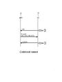
図1を参照して、本実施の形態に係るユーザ端末の構成を説明する。ユーザ端末10は、図1に例示するように、参照信号生成部101と、データ生成部102と、ビームフォーミング部103と、通信部104と、アンテナ105と、制御部106と、備える。
<ユーザ端末の構成>
図1を参照して、本実施の形態に係るユーザ端末の構成を説明する。ユーザ端末10は、図1に例示するように、参照信号生成部101と、データ生成部102と、ビームフォーミング部103と、通信部104と、アンテナ105と、制御部106と、備える。
なお、図1では、ユーザ端末10におけるOrthogonal Frequency Division Multiplexing(OFDM)信号を生成するための構成部(例えば、Inverse Fast Fourier Transform(IFFT)処理部、Cyclic Prefix(CP)付加部)等の記載を省略している。また、ユーザ端末10から送信される信号の信号波形はOFDM変調に基づく波形に限定されない。
参照信号生成部101は、チャネル推定に使用される参照信号(Reference Signal(RS))を生成し、ビームフォーミング部103に出力する。
データ生成部102は、基地局向けのデータ信号を生成する。また、データ生成部102は、符号化部111と変調部112とを備える。符号化部111及び変調部112は、基地局への信号のストリーム数(Mj個)に対応してそれぞれ備えられる。各符号化部111は、Mj個のストリームのデータ信号をそれぞれ符号化し、各変調部112は、符号化後のデータ信号をそれぞれ変調し、変調後のデータ信号をビームフォーミング部103に出力する。なお、各符号化部111及び各変調部112における符号化率及び/又は変調方式は、ストリーム毎に異なってもよい。
ビームフォーミング部103は、データ生成部102から入力されるデータ信号に対して、例えばコードブックに対応するプリコーディング行列を乗算し、Beamforming(BF)後のデータ信号(NT個の信号)を通信部104へ出力する。
通信部104は、NT個のアンテナ105(アンテナ素子)にそれぞれ対応して備えられる。通信部104は、入力される信号に対して、D/A(Digital/Analog)変換、アップコンバート等の送信処理を行い、送信処理後の信号を、例えば、時間、周波数又は符号によって多重し、NT個のアンテナ105からそれぞれ送信する。具体的には、通信部104は、データ送信時に、ビームフォーミング部103から入力されるストリームの信号を、アンテナ105を介して基地局へ送信(つまりUplink(UL)信号を送信)する。なお、通信部104は、送信部と呼んでもよい。
制御部106は、データ生成部102を制御する。また、制御部106は、ビームフォーミング部103を制御して、UL信号のBFを制御する。なお、以下の説明におけるユーザ端末の動作は、当該制御部106が行う制御によって実現する動作であってよい。また、以下の説明において、ユーザ端末10をUser Equipment(UE)、基地局をgNodeB(gNB)と表現する場合がある。
<検討>
図2を参照して、2又は4アンテナを備えるUE10が、コードブックに基づいて、UL信号送信のBFを行う手順について説明する。
図2を参照して、2又は4アンテナを備えるUE10が、コードブックに基づいて、UL信号送信のBFを行う手順について説明する。
UE10は、gNB20に対して、Sounding Reference Signal(SRS)を送信する。gNB20は、受信したSRSに基づき、UE10のリソース割当を決定し、UE10へULグラントを通知する。具体的には、gNB20は、UE10に対して、Scheduling Request indicator(SRI)、Transmitted Precoding Matrix Indicator(TPMI)、Transmitted Rank Indicator(TRI)、及び、Modulation and Coding Scheme(MCS)などを通知する。UE10は、UEグラントのPhysical Uplink Shared Channel(PUSCH)によって、BFを行ったUL信号をgNB20へ送信する。ここで、UE10は、gNB20から通知されたTPMIの示すコードブックに基づいて、BFを行う。
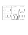
図3を参照して、UE10が2又は4アンテナを備える場合におけるcoherencyについて説明する。
2アンテナの場合、図3の「2-Tx」に示すように、2アンテナを1セットとして信号の位相を制御するfull-coherentと、2アンテナ間の信号の位相を制御しないnon-coherentと、の2ケースがある。
4アンテナの場合、図3の「4-Tx」に示すように、4アンテナを1セットとして信号の位相を制御するfull-coherentと、2アンテナを1セットとして信号の位相を制御し、かつ、2セット間の信号の位相を制御しないpartial-coherentと、4アンテナ間の信号の位相を制御しないnon-coherentと、の3ケースがある。
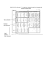
4アンテナの場合、図4に示すように、full-coherent、partial-coherent、及びnon-coherentの3ケースに応じて、異なるコードブック(プリコーディング行列)が規定されている。すなわち、図4に示すように、UE10がnon-coherentのみをサポートしている場合に用いるコードブック、UE10がpartial-coherentとnon-coherentをサポートしている場合に用いられるコードブック、UE10がfull-coherentとpartial-coherentとnon-coherentをサポートしている場合に用いられるコードブックが規定されている。
UE10が使用するコードブックは、次に述べるように、UE10のCapabilityに基づいて決定されてよい。すなわち、UE10は、NR規範(Release 15)におけるUE capabilityを用いて、図3に示したアンテナ構成に関する情報をgNB20へ報告する。報告されるアンテナ構成に関する情報は、例えば、アンテナ構成が、full-coherent、partial-coherent、及びnon-coherentのいずれの構成であるかを示す。gNB20は、UE capabilityに基づき、図4に示すコードブックからUE10のUL送信に用いられるコードブックを選択する。UE10の4アンテナがfull-coherentの構成である場合、UE10は、full-coherent、partial-coherent、及びnon-coherentのケースのコードブックをサポートすることを示すCapabilityの情報を報告してよい。UE10の4アンテナがpartial-coherentの構成である場合、UE10は、partial-coherent、及びnon-coherentのケースのコードブックをサポートすることを示すCapabilityの情報を報告してよい。UE10の4アンテナがnon-coherentの構成である場合、UE10は、non-coherentのケースのコードブックをサポートすることを示すCapabilityの情報を報告してよい。
<8アンテナを備えるUE>
上述ではUE10が2又は4アンテナを備える場合について説明した。しかし、UE10が多数(例えば5以上)のアンテナを備える場合、UL信号の伝送品質の向上を実現するためには、4アンテナの場合にgNB20へ通知する既存の情報のみでは、アンテナ構成に関する情報が不十分である。例えば、UE10が多数(例えば5以上)のアンテナを備える場合、アンテナを配置するパネル(アンテナパネル)の数、1パネルあたりのアンテナの数、及びパネルの位置関係等のパターンが、4アンテナの場合よりも増加する。そのため、多数(例えば5以上)のアンテナでは、partial-coherentであるアンテナ構成のパターンが、4アンテナの場合よりも増加する。このような場合、4アンテナの場合と同様にpartial-coherentであることを示すCapabilityの情報を報告するのでは、アンテナ構成に関する情報が不十分であり、gNB20は、適切なコードブック(プリコーディング行列)を選べない。以降、本実施の形態では便宜上、同一パネル内のアンテナはcoherent、異パネル間のアンテナはnon-coherentという例を用いて説明をしているが、アンテナ及び/又はcoherencyの前提は必ずしもこのような制約を有するわけではなく、coherencyとアンテナ構成とは独立と考えることも可能である。
上述ではUE10が2又は4アンテナを備える場合について説明した。しかし、UE10が多数(例えば5以上)のアンテナを備える場合、UL信号の伝送品質の向上を実現するためには、4アンテナの場合にgNB20へ通知する既存の情報のみでは、アンテナ構成に関する情報が不十分である。例えば、UE10が多数(例えば5以上)のアンテナを備える場合、アンテナを配置するパネル(アンテナパネル)の数、1パネルあたりのアンテナの数、及びパネルの位置関係等のパターンが、4アンテナの場合よりも増加する。そのため、多数(例えば5以上)のアンテナでは、partial-coherentであるアンテナ構成のパターンが、4アンテナの場合よりも増加する。このような場合、4アンテナの場合と同様にpartial-coherentであることを示すCapabilityの情報を報告するのでは、アンテナ構成に関する情報が不十分であり、gNB20は、適切なコードブック(プリコーディング行列)を選べない。以降、本実施の形態では便宜上、同一パネル内のアンテナはcoherent、異パネル間のアンテナはnon-coherentという例を用いて説明をしているが、アンテナ及び/又はcoherencyの前提は必ずしもこのような制約を有するわけではなく、coherencyとアンテナ構成とは独立と考えることも可能である。
そこで、本実施の形態では、UE10が8アンテナを備える場合を例にあげて、アンテナ構成に関する情報について説明する。
UE10のUL信号を送信するアンテナ数を8(またはそれ以上)に拡張すると、図5又は図6に例示するように、アンテナ構成のパターンは、4アンテナの場合よりも増大する。具体的には、UE10が8アンテナ以上を備える場合、アンテナ構成は、以下の(A1)、(A2)及び(A3)に関し、複数のパターンを取り得る。
(A1)coherency及び/又はパネル構成に関するパターン
4アンテナの場合、図3に示すように、partial-coherentのパターンは、1パターンである。これに対して、8アンテナの場合、図5の(b)と(c)、或いは、図6の(b)と(c)に例示するように、partial-coherentのパターンについても、2パターン以上を取り得る可能性がある。すなわち、8アンテナの場合、パネル構成が取り得るバリエーションが4アンテナの場合よりも多いため、partial-coherentのパターンが増大する。
4アンテナの場合、図3に示すように、partial-coherentのパターンは、1パターンである。これに対して、8アンテナの場合、図5の(b)と(c)、或いは、図6の(b)と(c)に例示するように、partial-coherentのパターンについても、2パターン以上を取り得る可能性がある。すなわち、8アンテナの場合、パネル構成が取り得るバリエーションが4アンテナの場合よりも多いため、partial-coherentのパターンが増大する。
(A2)アンテナ配列のパターン
4アンテナまでであれば、2つの単一偏波のアンテナを用いて1つの交差偏波を実現すると、交差偏波のアンテナは、1次元配列になる(2次元配列にはならない)。これに対して、8アンテナの場合、図6の(e)に例示するように、交差偏波を実現する2アンテナが2次元配列になる可能性がある。すなわち、8アンテナの場合、アンテナの配列パターンが、4アンテナの場合よりも増大する。
4アンテナまでであれば、2つの単一偏波のアンテナを用いて1つの交差偏波を実現すると、交差偏波のアンテナは、1次元配列になる(2次元配列にはならない)。これに対して、8アンテナの場合、図6の(e)に例示するように、交差偏波を実現する2アンテナが2次元配列になる可能性がある。すなわち、8アンテナの場合、アンテナの配列パターンが、4アンテナの場合よりも増大する。
(A3)偏波のパターン
8アンテナの場合、図5に例示するように、1アンテナずつ配列して単一偏波を実現するパターンと、図6に例示するように、2アンテナを用いて交差偏波を実現するパターンとを取り得る。すなわち、8アンテナの場合、偏波のパターンが4アンテナの場合よりも増大する。
8アンテナの場合、図5に例示するように、1アンテナずつ配列して単一偏波を実現するパターンと、図6に例示するように、2アンテナを用いて交差偏波を実現するパターンとを取り得る。すなわち、8アンテナの場合、偏波のパターンが4アンテナの場合よりも増大する。
上述のような様々なパターンに対応するために、本実施の形態では、以下の(B1)及び/又は(B2)の方法を採用する。
(B1)UE10が、UL信号の送信に用いるアンテナ構成に関する情報をgNB20へ通知する方法。
(B2)gNB20において、UE10がUL信号の送信に用いるアンテナ構成に応じたconfiguration(例えばコードブック)を設定する方法。
(B1)の方法には、partial-coherentのパターンを通知する方法(例えば、後述する(C1)、(C2))、および、partial-coherentか否かに関わらずアンテナ構成に関する情報を通知する方法(例えば、後述する(E1)~(E4))が含まれてよい。また、(B2)の方法には、partial-coherentのパターンに応じて、configuration(例えばコードブック)を設定する方法(例えば、後述する(D1)、(D2))、および、アンテナ構成に関する情報を通知する方法(例えば、後述する(F1)~(F4))が含まれてよい。
<partial-coherentのアンテナ構成のパターンの通知>
上述のとおり、UE10が8アンテナを備える場合、図5の(b)と(c)、或いは、図6の(b)と(c)に例示するように、partial-coherentのケースに関して、2パターンのアンテナ構成が考えられる。なお、partial-coherentのケースに関して、パネル201内はcoherent、パネル201間はnon-coherentであってよい。なお、図5の(b)及び(c)、並びに、図6の(b)及び(c)に示すパネル201の配置は、coherentとnon-coherentとをわかりやすく説明するための便宜的なものである。すなわち、図5及び図6は、当該図面のように配置されたパネル201をUE10が備えることを意味しない。
上述のとおり、UE10が8アンテナを備える場合、図5の(b)と(c)、或いは、図6の(b)と(c)に例示するように、partial-coherentのケースに関して、2パターンのアンテナ構成が考えられる。なお、partial-coherentのケースに関して、パネル201内はcoherent、パネル201間はnon-coherentであってよい。なお、図5の(b)及び(c)、並びに、図6の(b)及び(c)に示すパネル201の配置は、coherentとnon-coherentとをわかりやすく説明するための便宜的なものである。すなわち、図5及び図6は、当該図面のように配置されたパネル201をUE10が備えることを意味しない。
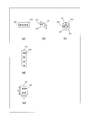
図5の(b)は、2つのパネル201を有し、各パネル201に4つのアンテナ105が配置されるアンテナ構成を示す。図5の(b)のアンテナ構成では、8アンテナのうち、coherentとなるアンテナの数が最大で4である。図5の(c)は、4つのパネル201を有し、各パネル201に2つのアンテナ105が配置されるアンテナ構成を示す。図5の(c)のアンテナ構成では、8アンテナのうち、coherentとなるアンテナの数が2である。
図6の(b)は、2つのパネル201を有し、各パネル201に交差偏波のアンテナ105が2つ配置されるアンテナ構成を示す。図6の(b)のアンテナ構成では、8アンテナ(4つの交差偏波のアンテナ)のうち、coherentとなるアンテナの数が最大で4である(2つの交差偏波のアンテナがcoherent)。図6の(c)は、4つのパネル201を有し、各パネル201に交差偏波のアンテナ105が1つ配置されるアンテナ構成を示す。図6の(c)のアンテナ構成では、8アンテナのうち、coherentとなるアンテナの数が2である。
上記のように、8アンテナの場合、図5の(b)と(c)との比較、および、図6の(b)と(c)との比較に示すように、同一の偏波(単一偏波または交差偏波)のpartial-coherentのケースであっても、1パネルあたりのアンテナ数(または、coherentとなるアンテナの最大数)が異なるパターンが考えられる。また、8アンテナの場合、図5の(b)と図6の(b)との比較、および、図5の(c)と図6の(c)との比較に示すように、1パネルあたりのアンテナ数(または、coherentとなるアンテナの最大数)が同一のpartial-coherentのケースであっても、偏波が異なるパターンが考えられる。
そこで、UE10は、当該UE10が、partial-coherentのケースに関して、何れのパターンのアンテナ構成であるかをgNB20へ通知する。例えば、以下の(C1)及び/又は(C2)の方法によって通知する。
(C1)partial-coherentの2パターンのアンテナ構成に、Type1及びType2をそれぞれ対応付け、UE10は、Type1又はType2を示す情報をgNB20へ通知する。
(C2)partial-coherentの2パターンのアンテナ構成に、partial-coherent type1及びpartial-coherent type2をそれぞれ対応付け、UE10は、full-coherent、partial-coherent type1、partial-coherent type2、及び、non-coherentの何れか1つを示す情報をgNB20に通知する。
なお、(C2)において、例えば、UE10は、NR規範(Release 15)におけるUE capabilityを用いてpartial-coherentに対応していることをgNB20へ報告した場合、当該partial-coherentを報告するUE capabilityとは異なる新しいUE capabilityを用いて、UE10のpartial-coherentのパターンの想定(例えば、type1又はtype2の想定)を、gNB20へ報告してもよい。また、UE10は、NR規範(Release 15)におけるUE capabilityを用いてpartial-coherentをgNB20へ報告し、partial-coherentのパターンの想定(例えば、type1又はtype2の想定)をgNB20に報告しない場合、gNB20は当該UE10からtype1(或いはtype2)を報告されたと想定してコードブック(又はUL beam management)を設定するものと想定してよい。
また、(C2)において、UE10は、full-coherent、partial-coherent及びnon-coherentの1又は2以上の何れに対応しているかと、UE10のpartial-coherentのパターンの想定(例えば、type1又はtype2)を、NR規範(Release 16)における1つのUE capabilityを用いて、gNB20へ報告してもよい。
また、(C2)において、UE10は、偏波構成の違いについて、gNB20へ通知してよい。例えば、単一偏波のpartial-coherentの2パターンのアンテナ構成(例えば図5の(b)と(c))にType1及びtype2を、交差偏波のpartial-coherentの2パターンのアンテナ構成(例えば図6の(b)と(c))にType3及びType4を対応付け、UE10は、type1からType4の何れか1つを示す情報をgNB20へ通知してもよい。或いは、UE10は、偏波構成については、別途(独立に)gNB20へ通知してもよい。
なお、本実施の形態では、8アンテナの場合における、partial-coherentのパターンのアンテナ構成について説明している。しかし、アンテナ数が8よりも多い場合についても、同様の概念に基づいて、本実施の形態を適用可能である。
また、本実施の形態では、partial-coherentのアンテナ構成が、2パターンである例を示したが、partial-coherentのアンテナ構成は、3パターン以上であってもよい。例えば、16アンテナの場合のpartial-coherentのアンテナ構成には、2つのパネルを有し、各パネルに6つのアンテナが配置される構成と、3つのパネルを有し、各パネルに4つのアンテナが配置される構成と、4つのパネルを有し、各パネルに3つのアンテナが配置される構成と、6つのパネルを有し、各パネルに2つのアンテナが配置される構成と、の少なくとも4つのパターンが想定される。
<コードブックの決定>
partial-coherentのアンテナ構成のパターンが異なる場合は、適切なコードブックも異なり得る。例えば、上記のように、図5の(b)と(c)とは、いずれもpartial-coherentのアンテナ構成のパターンである。図5の(b)のアンテナ構成では、8アンテナのうち、coherentとなるアンテナの数が最大で4であり、図5の(c)のアンテナ構成では、8アンテナのうち、coherentとなるアンテナの数が2である。そのため、図5の(b)のアンテナ構成では、8アンテナのうち、2つのアンテナがcoherentである場合のコードブックと、3つのアンテナがcoherentである場合のコードブックと、4つのアンテナがcoherentである場合のコードブックとをサポートすることが想定される。一方で、図5の(c)のアンテナ構成では、8アンテナのうち、2つのアンテナがcoherentである場合のコードブックをサポートすること、および、2より多いアンテナがcoherentである場合のコードブックをサポートしないことが想定される。
partial-coherentのアンテナ構成のパターンが異なる場合は、適切なコードブックも異なり得る。例えば、上記のように、図5の(b)と(c)とは、いずれもpartial-coherentのアンテナ構成のパターンである。図5の(b)のアンテナ構成では、8アンテナのうち、coherentとなるアンテナの数が最大で4であり、図5の(c)のアンテナ構成では、8アンテナのうち、coherentとなるアンテナの数が2である。そのため、図5の(b)のアンテナ構成では、8アンテナのうち、2つのアンテナがcoherentである場合のコードブックと、3つのアンテナがcoherentである場合のコードブックと、4つのアンテナがcoherentである場合のコードブックとをサポートすることが想定される。一方で、図5の(c)のアンテナ構成では、8アンテナのうち、2つのアンテナがcoherentである場合のコードブックをサポートすること、および、2より多いアンテナがcoherentである場合のコードブックをサポートしないことが想定される。
そこで、UE10及びgNB20は、partial-coherentのアンテナ構成のパターンに基づいて、例えば、以下の(D1)及び/又は(D2)の方法によって、コードブックを切り替える。
(D1)coherency typeに応じて異なるコードブックを対応付ける。この場合、gNB20は、UE10から通知されたcoherency typeに応じて、コードブックの設定を切り替えてよい。
(D2)gNB20は、UE10から通知されたcoherency typeに応じて、下りシグナリングDownlink Control Information(DCI)の内容を変更する。この場合、UE10は、受信したDCIに基づいて、コードブックの設定を想定してよい(NR規範(Release 15))。例えば、gNB20は、DCIの内容の変更に関する情報を、UE10へ通知してもよい。なお、gNB20は、当該コードブックの設定を、既存のコードブックのサブセットとしてUE10へ通知してもよい。
なお、UE10は、UE capabilityシグナリングによってcoherency typeをgNB20へ報告した場合、gNB20から設定されるコードブック(又はUL beam management)については、当該gNB20へ報告したcoherency typeに制限されると想定してもよい。
上記の(C1)、(C2)では、UE10が、partial-coherentのケースに関して、何れのパターンのアンテナ構成であるかをgNB20へ通知する方法について示した。次に、UE10が、partial-coherentのアンテナ構成であるか否かに関わらず、アンテナ構成に関する情報をgNB20へ通知する方法を説明する。
<アンテナ構成に関する情報の通知>
UE10は、次の(E1)から(E4)の少なくとも1つの方法によって、当該UE10のアンテナ構成に関する情報をgNB20へ通知してよい。
UE10は、次の(E1)から(E4)の少なくとも1つの方法によって、当該UE10のアンテナ構成に関する情報をgNB20へ通知してよい。
(E1)UE10は、2つの自然数V,Hを用いて、アンテナ配列をgNB20へ通知してもよい。例えば、UE10は、図5の(e)に例示するアンテナ配列を備える場合、V=4、H=2をgNB20へ通知してよい。例えば、UE10は、図6の(e)に例示するアンテナ配列を備える場合、UE10は、V=2、H=2をgNB20へ通知してよい。当該アンテナ配列の情報は必ずしもVおよびHで表現される必要はない。例えば、アンテナ配列の情報は、これらの組み合わせとしてアンテナ配列タイプなどとして通知されてもよい。
(E2)UE10は、偏波構成の情報をgNB20へ通知してよい。偏波構成の情報には、偏波構成の種別と偏波面の数との少なくとも1つが含まれてよい。例えば、UE10は、アンテナ105の偏波構成の種別が、単一偏波又は交差偏波の何れであるかを示す偏波構成の情報を、gNB20へ通知してよい。又は、UE10は、偏波面の数として1または2などの数値を、gNB20へ通知してよい。
(E3)UE10は、1パネル201あたりのアンテナ構成をgNB20へ通知してよい。この場合、gNB20は、複数のパネル201においてアンテナ構成が共通であると想定してもよい。例えば、UE10は、図5の(b)に例示するアンテナ構成を備える場合、1パネル201あたり単一偏波の4アンテナを備えることを通知してよい。例えば、UE10は、図5の(c)に例示するアンテナ構成を備える場合、1パネル201あたり単一偏波の2アンテナを備えることを通知してよい。例えば、UE10は、図6の(b)に例示するアンテナ構成を備える場合、1パネル201あたり交差偏波の4アンテナ(2アンテナの2セット)を備えることを通知してよい。例えば、UE10は、図6の(c)に例示するアンテナ構成を備える場合、1パネル201あたり交差偏波の2アンテナ(2アンテナの1セット)を備えることを通知してよい。
(E4)UE10は、パネル201毎のアンテナ構成をgNB201へ通知してよい。例えば、UE10は、図5の(b)に例示するアンテナ構成を備える場合、第1のパネル201は単一偏波の4アンテナを備え、第2のパネル201は単一偏波の4アンテナを備えることを通知してよい。図5の(c)についても同様である。また、例えば、UE10は、図6の(b)に例示するアンテナ構成を備える場合、第1のパネル201は交差偏波の4アンテナ(2アンテナの2セット)を備え、第2のパネル201は交差偏波の4アンテナ(2アンテナの2セット)を備えることを通知してよい。図6の(c)についても同様である。
なお、アンテナ構成を通知する方法は、上記(C1)、(C2)と、(E1)~(E4)のうち、いずれか1つであってもよいし、いずれか2つ以上の組み合わせであってもよい。
また、gNB20は、次の(F1)及び(F2)の少なくとも1つに応じてコードブックの設定を切り替えてよい。
(F1)gNB20は、UE10から通知された2つの自然数V,Hに応じて、コードブックの設定を切り替える。例えば、UE10は、アンテナ構成をcodebookConfigN1、codebookConfigN2などとして、各次元のアンテナ構成をgNB20へ通知してもよい。
(F2)gNB20は、UE10から通知された偏波構成に応じて、コードブックの設定を切り替える。例えば、gNB20は、偏波構成の種別が単一偏波又は交差偏波の何れであるかに応じて、コードブックの設定を切り替える。或いは、gNB20は、UE10から通知された偏波面の数に応じて、コードブックの設定を切り替える。
なお、configurationを切り替える方法は、上記(D1)、(D2)と、(F1)、(F2)のうち、いずれか1つであってもよいし、いずれか2つ以上の組み合わせであってもよい。
なお、UE10のアンテナ構成は、上述以外の要素によって暗示的(implicit)にgNB20へ通知されてもよい。例えば、上述において、UE10のアンテナ構成(及び/又はアンテナ数)を通知するために用いたUE capabilityシグナリングは、最大レイヤ数及び/又はDemodulation Reference Signal(DM-RS)ポート数から想定されるものであってもよいし、SRSポート数から想定されるものであってもよい。
<注記>
本実施の形態は、上りリンク及び下りリンク、並びに、送信及び受信の区別に関わらず、適用可能である。この場合、上り信号(又はチャネル)と下り信号(又はチャネル)については、相互に読み替え可能である。また、上りフィードバック情報と、下り制御シグナリングとは、相互に読み替え可能である。
本実施の形態は、上りリンク及び下りリンク、並びに、送信及び受信の区別に関わらず、適用可能である。この場合、上り信号(又はチャネル)と下り信号(又はチャネル)については、相互に読み替え可能である。また、上りフィードバック情報と、下り制御シグナリングとは、相互に読み替え可能である。
本実施の形態では、主にNew Radio(NR)のチャネル及びシグナリング方式を前提として説明したが、本実施の形態は、NRと同様の機能を有するチャネル及びシグナリング方式に適用可能である。例えば、本実施の形態は、LTE/LTE-Aにも適用可能である。
本実施の形態にて例示したシグナリングは、明示的(explicit)な方法に限定されず、暗示的(implicit)に通知されてもよいし、仕様で一意に定められてもよい。
また、本実施の形態にて例示したシグナリングは、当該例示に限られない。例えば、Radio Resource Control(RRC)、Medium Access Control(MAC) Control Element(CE)、DCIなど、異なるレイヤを用いたシグナリングであってもよいし、Master Information Block(MIB)、System Information Block(SIB)などを用いたシグナリングであってもよい。或いは、RRCとDCIとを組み合わせたシグナリングであってもよいし、RRCとMAC CEとを組み合わせたシグナリングであってもよいし、RRCとMAC CEとDCIとをすべて組み合わせたシグナリングであってもよい。
本実施の形態では、ビーム、BF又はRS等と表現している場合もあるが、物理信号及び/又はチャネルがビームフォーミングされているか否かについては、基地局及び/又は端末からtransparentであってもよい。すなわち、ビーム、BF又はRS等の表現は、信号又はRS等と言い換え可能である。また、ビームフォーミングされているRSを、RSリソースと言い換えてもよい。同様に、ビーム選択を、リソース選択と言い換えてもよい。また、ビームインデックスを、リソースインデックス又はアンテナポートインデックス等と言い換えてもよい。
本実施の形態におけるパネル201は、便宜的な表現であり、他の表現が用いられてもよい。例えば、パネル201は、アンテナ、アンテナパネル、アンテナグループ、ビーム、Spatial filter、RSリソース、Quasi-collocation(QCL)、又は、Transmission Configuration Indicator(TCI)によって表現されてもよい。また、これらをグルーピングした概念によって、パネルを表現してもよい。また、アンテナ105は、例えば、ポート、アンテナポート、SRSポート、アンテナ素子と言い換えてよい。
本実施の形態は、Channel State Information(CSI)測定、チャネルサウンディング、Beam management等としても適用可能である。また、本実施の形態は、その他のビーム制御等のリンク制御に対しても、適用可能である。
本実施の形態におけるResource Block(RB)とサブキャリアとは互いに置換可能である。同様に、本実施の形態におけるスロットとシンボルとは互いに置換可能である。
上述した実施例及び変形例は、互いに組み合わせ可能である。また、例示した各特徴は、互いに組み合わせ可能である。また、本願発明は、本明細書に例示した特徴の特定の組み合わせに限定されない。
本実施の形態では、主に、アンテナ数が8の場合について示したが、本実施の形態は、この場合に限定されない。例えばアンテナ数が6、12、16の場合、或いはそれ以外の場合においても、本実施の形態は適用可能である。
<本実施の形態のまとめ>
本実施の形態に係るユーザ端末10は、複数のアンテナ105を有する通信部(送信部)104と、複数のアンテナ105から基地局20へ送信される信号の位相を制御する制御部106と、を備え、制御部106は、第1情報および第2情報の何れか1つを基地局20へ通知する制御を行う。第1情報は、複数のアンテナ105の全部がコヒーレントである場合の、各アンテナ105が採り得る複数の配置パターンの何れかを示す情報である。第2情報は、複数のアンテナ105の少なくとも2つがコヒーレントである場合の、コヒーレントであるアンテナ105の数を示す情報である。
本実施の形態に係るユーザ端末10は、複数のアンテナ105を有する通信部(送信部)104と、複数のアンテナ105から基地局20へ送信される信号の位相を制御する制御部106と、を備え、制御部106は、第1情報および第2情報の何れか1つを基地局20へ通知する制御を行う。第1情報は、複数のアンテナ105の全部がコヒーレントである場合の、各アンテナ105が採り得る複数の配置パターンの何れかを示す情報である。第2情報は、複数のアンテナ105の少なくとも2つがコヒーレントである場合の、コヒーレントであるアンテナ105の数を示す情報である。
上記構成によれば、基地局20は、ユーザ端末10から通知される第1情報又は第2情報(つまり、アンテナ構成に関する情報)から、ユーザ端末10が備える複数のアンテナ105(例えば8アンテナ)の構成を認識でき、当該アンテナ構成に適切なコードブックをユーザ端末10へ通知できる。よって、ユーザ端末10と基地局20との間におけるUL信号の伝送品質を向上させることができる。
以上、本開示の実施の形態について説明した。
<ハードウェア構成>
なお、上記実施の形態の説明に用いたブロック図は、機能単位のブロックを示している。これらの機能ブロック(構成部)は、ハードウェア及び/又はソフトウェアの任意の組み合わせによって実現される。また、各機能ブロックの実現手段は特に限定されない。すなわち、各機能ブロックは、物理的及び/又は論理的に結合した1つの装置により実現されてもよいし、物理的及び/又は論理的に分離した2つ以上の装置を直接的及び/又は間接的に(例えば、有線及び/又は無線)で接続し、これら複数の装置により実現されてもよい。
なお、上記実施の形態の説明に用いたブロック図は、機能単位のブロックを示している。これらの機能ブロック(構成部)は、ハードウェア及び/又はソフトウェアの任意の組み合わせによって実現される。また、各機能ブロックの実現手段は特に限定されない。すなわち、各機能ブロックは、物理的及び/又は論理的に結合した1つの装置により実現されてもよいし、物理的及び/又は論理的に分離した2つ以上の装置を直接的及び/又は間接的に(例えば、有線及び/又は無線)で接続し、これら複数の装置により実現されてもよい。
例えば、本発明の一実施の形態におけるユーザ端末10及び基地局20などは、本発明の無線通信方法の処理を行うコンピュータとして機能してもよい。図7は、本発明の一実施の形態に係るユーザ端末10及び基地局20のハードウェア構成の一例を示す図である。上述のユーザ端末10及び基地局20は、物理的には、プロセッサ1001、メモリ1002、ストレージ1003、通信装置1004、入力装置1005、出力装置1006、バス1007などを含むコンピュータ装置として構成されてもよい。
なお、以下の説明では、「装置」という文言は、回路、デバイス、ユニットなどに読み替えることができる。ユーザ端末10及び基地局20のハードウェア構成は、図に示した各装置を1つ又は複数含むように構成されてもよいし、一部の装置を含まずに構成されてもよい。
ユーザ端末10及び基地局20における各機能は、プロセッサ1001、メモリ1002などのハードウェア上に所定のソフトウェア(プログラム)を読み込ませることで、プロセッサ1001が演算を行い、通信装置1004による通信や、メモリ1002及びストレージ1003におけるデータの読み出し及び/又は書き込みを制御することで実現される。
プロセッサ1001は、例えば、オペレーティングシステムを動作させてコンピュータ全体を制御する。プロセッサ1001は、周辺装置とのインターフェース、制御装置、演算装置、レジスタなどを含む中央処理装置(CPU:Central Processing Unit)で構成されてもよい。例えば、上述の参照信号生成部101、データ生成部102、ビームフォーミング部103、通信部104、制御部106などは、プロセッサ1001で実現されてもよい。
また、プロセッサ1001は、プログラム(プログラムコード)、ソフトウェアモジュールやデータを、ストレージ1003及び/又は通信装置1004からメモリ1002に読み出し、これらに従って各種の処理を実行する。プログラムとしては、上述の実施の形態で説明した動作の少なくとも一部をコンピュータに実行させるプログラムが用いられる。例えば、制御部106は、メモリ1002に格納され、プロセッサ1001で動作する制御プログラムによって実現されてもよく、他の機能ブロックについても同様に実現されてもよい。上述の各種処理は、1つのプロセッサ1001で実行される旨を説明してきたが、2以上のプロセッサ1001により同時又は逐次に実行されてもよい。プロセッサ1001は、1以上のチップで実装されてもよい。なお、プログラムは、電気通信回線を介してネットワークから送信されても良い。
メモリ1002は、コンピュータ読み取り可能な記録媒体であり、例えば、ROM(Read Only Memory)、EPROM(Erasable Programmable ROM)、EEPROM(Electrically Erasable Programmable ROM)、RAM(Random Access Memory)などの少なくとも1つで構成されてもよい。メモリ1002は、レジスタ、キャッシュ、メインメモリ(主記憶装置)などと呼ばれてもよい。メモリ1002は、本発明の一実施の形態に係る無線通信方法を実施するために実行可能なプログラム(プログラムコード)、ソフトウェアモジュールなどを保存することができる。
ストレージ1003は、コンピュータ読み取り可能な記録媒体であり、例えば、CD-ROM(Compact Disc ROM)などの光ディスク、ハードディスクドライブ、フレキシブルディスク、光磁気ディスク(例えば、コンパクトディスク、デジタル多用途ディスク、Blu-ray(登録商標)ディスク)、スマートカード、フラッシュメモリ(例えば、カード、スティック、キードライブ)、フロッピー(登録商標)ディスク、磁気ストリップなどの少なくとも1つで構成されてもよい。ストレージ1003は、補助記憶装置と呼ばれてもよい。上述の記憶媒体は、例えば、メモリ1002及び/又はストレージ1003を含むデータベース、サーバその他の適切な媒体であってもよい。
通信装置1004は、有線及び/又は無線ネットワークを介してコンピュータ間の通信を行うためのハードウェア(送受信デバイス)であり、例えばネットワークデバイス、ネットワークコントローラ、ネットワークカード、通信モジュールなどともいう。例えば、上述の通信部104などは、通信装置1004で実現されてもよい。
入力装置1005は、外部からの入力を受け付ける入力デバイス(例えば、キーボード、マウス、マイクロフォン、スイッチ、ボタン、センサなど)である。出力装置1006は、外部への出力を実施する出力デバイス(例えば、ディスプレイ、スピーカー、LEDランプなど)である。なお、入力装置1005及び出力装置1006は、一体となった構成(例えば、タッチパネル)であってもよい。
また、プロセッサ1001やメモリ1002などの各装置は、情報を通信するためのバス1007で接続される。バス1007は、単一のバスで構成されてもよいし、装置間で異なるバスで構成されてもよい。
また、ユーザ端末10及び基地局20は、マイクロプロセッサ、デジタル信号プロセッサ(DSP:Digital Signal Processor)、ASIC(Application Specific Integrated Circuit)、PLD(Programmable Logic Device)、FPGA(Field Programmable Gate Array)などのハードウェアを含んで構成されてもよく、当該ハードウェアにより、各機能ブロックの一部又は全てが実現されてもよい。例えば、プロセッサ1001は、これらのハードウェアの少なくとも1つで実装されてもよい。
<情報の通知、シグナリング>
情報の通知は、本明細書で説明した態様/実施形態に限られず、他の方法で行われてもよい。例えば、情報の通知は、物理レイヤシグナリング(例えば、DCI(Downlink Control Information)、UCI(Uplink Control Information))、上位レイヤシグナリング(例えば、RRC(Radio Resource Control)シグナリング、MAC(Medium Access Control)シグナリング、報知情報(MIB(Master Information Block)、SIB(System Information Block)))、その他の信号又はこれらの組み合わせによって実施されてもよい。また、RRCシグナリングは、RRCメッセージと呼ばれてもよく、例えば、RRC接続セットアップ(RRC Connection Setup)メッセージ、RRC接続再構成(RRC Connection Reconfiguration)メッセージなどであってもよい。
情報の通知は、本明細書で説明した態様/実施形態に限られず、他の方法で行われてもよい。例えば、情報の通知は、物理レイヤシグナリング(例えば、DCI(Downlink Control Information)、UCI(Uplink Control Information))、上位レイヤシグナリング(例えば、RRC(Radio Resource Control)シグナリング、MAC(Medium Access Control)シグナリング、報知情報(MIB(Master Information Block)、SIB(System Information Block)))、その他の信号又はこれらの組み合わせによって実施されてもよい。また、RRCシグナリングは、RRCメッセージと呼ばれてもよく、例えば、RRC接続セットアップ(RRC Connection Setup)メッセージ、RRC接続再構成(RRC Connection Reconfiguration)メッセージなどであってもよい。
<適用システム>
本明細書で説明した各態様/実施形態は、LTE(Long Term Evolution)、LTE-A(LTE-Advanced)、SUPER 3G、IMT-Advanced、4G、5G、FRA(Future Radio Access)、W-CDMA(登録商標)、GSM(登録商標)、CDMA2000、UMB(Ultra Mobile Broadband)、IEEE 802.11(Wi-Fi)、IEEE 802.16(WiMAX)、IEEE 802.20、UWB(Ultra-WideBand)、Bluetooth(登録商標)、その他の適切なシステムを利用するシステム及び/又はこれらに基づいて拡張された次世代システムに適用されてもよい。
本明細書で説明した各態様/実施形態は、LTE(Long Term Evolution)、LTE-A(LTE-Advanced)、SUPER 3G、IMT-Advanced、4G、5G、FRA(Future Radio Access)、W-CDMA(登録商標)、GSM(登録商標)、CDMA2000、UMB(Ultra Mobile Broadband)、IEEE 802.11(Wi-Fi)、IEEE 802.16(WiMAX)、IEEE 802.20、UWB(Ultra-WideBand)、Bluetooth(登録商標)、その他の適切なシステムを利用するシステム及び/又はこれらに基づいて拡張された次世代システムに適用されてもよい。
<処理手順等>
本明細書で説明した各態様/実施形態の処理手順、シーケンス、フローチャートなどは、矛盾の無い限り、順序を入れ替えてもよい。例えば、本明細書で説明した方法については、例示的な順序で様々なステップの要素を提示しており、提示した特定の順序に限定されない。
本明細書で説明した各態様/実施形態の処理手順、シーケンス、フローチャートなどは、矛盾の無い限り、順序を入れ替えてもよい。例えば、本明細書で説明した方法については、例示的な順序で様々なステップの要素を提示しており、提示した特定の順序に限定されない。
<基地局の動作>
本明細書において基地局によって行われるとした特定動作は、場合によってはその上位ノード(upper node)によって行われることもある。基地局を有する1つまたは複数のネットワークノード(network nodes)からなるネットワークにおいて、端末との通信のために行われる様々な動作は、基地局および/または基地局以外の他のネットワークノード(例えば、MMEまたはS-GWなどが考えられるが、これらに限られない)によって行われ得ることは明らかである。上記において基地局以外の他のネットワークノードが1つである場合を例示したが、複数の他のネットワークノードの組み合わせ(例えば、MMEおよびS-GW)であってもよい。
本明細書において基地局によって行われるとした特定動作は、場合によってはその上位ノード(upper node)によって行われることもある。基地局を有する1つまたは複数のネットワークノード(network nodes)からなるネットワークにおいて、端末との通信のために行われる様々な動作は、基地局および/または基地局以外の他のネットワークノード(例えば、MMEまたはS-GWなどが考えられるが、これらに限られない)によって行われ得ることは明らかである。上記において基地局以外の他のネットワークノードが1つである場合を例示したが、複数の他のネットワークノードの組み合わせ(例えば、MMEおよびS-GW)であってもよい。
<入出力の方向>
情報等(※「情報、信号」の項目参照)は、上位レイヤ(または下位レイヤ)から下位レイヤ(または上位レイヤ)へ出力され得る。複数のネットワークノードを介して入出力されてもよい。
情報等(※「情報、信号」の項目参照)は、上位レイヤ(または下位レイヤ)から下位レイヤ(または上位レイヤ)へ出力され得る。複数のネットワークノードを介して入出力されてもよい。
<入出力された情報等の扱い>
入出力された情報等は特定の場所(例えば、メモリ)に保存されてもよいし、管理テーブルで管理してもよい。入出力される情報等は、上書き、更新、または追記され得る。出力された情報等は削除されてもよい。入力された情報等は他の装置へ送信されてもよい。
入出力された情報等は特定の場所(例えば、メモリ)に保存されてもよいし、管理テーブルで管理してもよい。入出力される情報等は、上書き、更新、または追記され得る。出力された情報等は削除されてもよい。入力された情報等は他の装置へ送信されてもよい。
<判定方法>
判定は、1ビットで表される値(0か1か)によって行われてもよいし、真偽値(Boolean:trueまたはfalse)によって行われてもよいし、数値の比較(例えば、所定の値との比較)によって行われてもよい。
判定は、1ビットで表される値(0か1か)によって行われてもよいし、真偽値(Boolean:trueまたはfalse)によって行われてもよいし、数値の比較(例えば、所定の値との比較)によって行われてもよい。
<態様のバリエーション等>
本明細書で説明した各態様/実施形態は単独で用いてもよいし、組み合わせて用いてもよいし、実行に伴って切り替えて用いてもよい。また、所定の情報の通知(例えば、「Xであること」の通知)は、明示的に行うものに限られず、暗黙的(例えば、当該所定の情報の通知を行わない)ことによって行われてもよい。
本明細書で説明した各態様/実施形態は単独で用いてもよいし、組み合わせて用いてもよいし、実行に伴って切り替えて用いてもよい。また、所定の情報の通知(例えば、「Xであること」の通知)は、明示的に行うものに限られず、暗黙的(例えば、当該所定の情報の通知を行わない)ことによって行われてもよい。
以上、本発明について詳細に説明したが、当業者にとっては、本発明が本明細書中に説明した実施形態に限定されるものではないということは明らかである。本発明は、特許請求の範囲の記載により定まる本発明の趣旨及び範囲を逸脱することなく修正及び変更態様として実施することができる。したがって、本明細書の記載は、例示説明を目的とするものであり、本発明に対して何ら制限的な意味を有するものではない。
(用語の意味、解釈)
<ソフトウェア>
ソフトウェアは、ソフトウェア、ファームウェア、ミドルウェア、マイクロコード、ハードウェア記述言語と呼ばれるか、他の名称で呼ばれるかを問わず、命令、命令セット、コード、コードセグメント、プログラムコード、プログラム、サブプログラム、ソフトウェアモジュール、アプリケーション、ソフトウェアアプリケーション、ソフトウェアパッケージ、ルーチン、サブルーチン、オブジェクト、実行可能ファイル、実行スレッド、手順、機能などを意味するよう広く解釈されるべきである。
<ソフトウェア>
ソフトウェアは、ソフトウェア、ファームウェア、ミドルウェア、マイクロコード、ハードウェア記述言語と呼ばれるか、他の名称で呼ばれるかを問わず、命令、命令セット、コード、コードセグメント、プログラムコード、プログラム、サブプログラム、ソフトウェアモジュール、アプリケーション、ソフトウェアアプリケーション、ソフトウェアパッケージ、ルーチン、サブルーチン、オブジェクト、実行可能ファイル、実行スレッド、手順、機能などを意味するよう広く解釈されるべきである。
また、ソフトウェア、命令などは、伝送媒体を介して送受信されてもよい。例えば、ソフトウェアが、同軸ケーブル、光ファイバケーブル、ツイストペア及びデジタル加入者回線(DSL)などの有線技術及び/又は赤外線、無線及びマイクロ波などの無線技術を使用してウェブサイト、サーバ、又は他のリモートソースから送信される場合、これらの有線技術及び/又は無線技術は、伝送媒体の定義内に含まれる。
<情報、信号>
本明細書で説明した情報、信号などは、様々な異なる技術のいずれかを使用して表されてもよい。例えば、上記の説明全体に渡って言及され得るデータ、命令、コマンド、情報、信号、ビット、シンボル、チップなどは、電圧、電流、電磁波、磁界若しくは磁性粒子、光場若しくは光子、又はこれらの任意の組み合わせによって表されてもよい。
本明細書で説明した情報、信号などは、様々な異なる技術のいずれかを使用して表されてもよい。例えば、上記の説明全体に渡って言及され得るデータ、命令、コマンド、情報、信号、ビット、シンボル、チップなどは、電圧、電流、電磁波、磁界若しくは磁性粒子、光場若しくは光子、又はこれらの任意の組み合わせによって表されてもよい。
なお、本明細書で説明した用語及び/又は本明細書の理解に必要な用語については、同一の又は類似する意味を有する用語と置き換えてもよい。例えば、チャネル及び/又はシンボルは信号(シグナル)であってもよい。また、信号はメッセージであってもよい。また、コンポーネントキャリア(CC)は、キャリア周波数、セルなどと呼ばれてもよい。
<「システム」、「ネットワーク」>
本明細書で使用する「システム」および「ネットワーク」という用語は、互換的に使用される。
本明細書で使用する「システム」および「ネットワーク」という用語は、互換的に使用される。
<パラメータ、チャネルの名称>
また、本明細書で説明した情報、パラメータなどは、絶対値で表されてもよいし、所定の値からの相対値で表されてもよいし、対応する別の情報で表されてもよい。例えば、無線リソースはインデックスで指示されるものであってもよい。
また、本明細書で説明した情報、パラメータなどは、絶対値で表されてもよいし、所定の値からの相対値で表されてもよいし、対応する別の情報で表されてもよい。例えば、無線リソースはインデックスで指示されるものであってもよい。
上述したパラメータに使用する名称はいかなる点においても限定的なものではない。さらに、これらのパラメータを使用する数式等は、本明細書で明示的に開示したものと異なる場合もある。様々なチャネル(例えば、PUCCH、PDCCHなど)及び情報要素(例えば、TPCなど)は、あらゆる好適な名称によって識別できるので、これらの様々なチャネル及び情報要素に割り当てている様々な名称は、いかなる点においても限定的なものではない。
<基地局>
基地局は、1つまたは複数(例えば、3つ)の(セクタとも呼ばれる)セルを収容することができる。基地局が複数のセルを収容する場合、基地局のカバレッジエリア全体は複数のより小さいエリアに区分でき、各々のより小さいエリアは、基地局サブシステム(例えば、屋内用の小型基地局RRH:Remote Radio Head)によって通信サービスを提供することもできる。「セル」または「セクタ」という用語は、このカバレッジにおいて通信サービスを行う基地局、および/または基地局サブシステムのカバレッジエリアの一部または全体を指す。さらに、「基地局」「eNB」、「セル」、および「セクタ」という用語は、本明細書では互換的に使用され得る。基地局は、固定局(fixed station)、NodeB、eNodeB(eNB)、アクセスポイント(access point)、フェムトセル、スモールセルなどの用語で呼ばれる場合もある。
基地局は、1つまたは複数(例えば、3つ)の(セクタとも呼ばれる)セルを収容することができる。基地局が複数のセルを収容する場合、基地局のカバレッジエリア全体は複数のより小さいエリアに区分でき、各々のより小さいエリアは、基地局サブシステム(例えば、屋内用の小型基地局RRH:Remote Radio Head)によって通信サービスを提供することもできる。「セル」または「セクタ」という用語は、このカバレッジにおいて通信サービスを行う基地局、および/または基地局サブシステムのカバレッジエリアの一部または全体を指す。さらに、「基地局」「eNB」、「セル」、および「セクタ」という用語は、本明細書では互換的に使用され得る。基地局は、固定局(fixed station)、NodeB、eNodeB(eNB)、アクセスポイント(access point)、フェムトセル、スモールセルなどの用語で呼ばれる場合もある。
<移動局>
移動局は、当業者によって、加入者局、モバイルユニット、加入者ユニット、ワイヤレスユニット、リモートユニット、モバイルデバイス、ワイヤレスデバイス、ワイヤレス通信デバイス、リモートデバイス、モバイル加入者局、アクセス端末、モバイル端末、ワイヤレス端末、リモート端末、ハンドセット、ユーザエージェント、モバイルクライアント、クライアント、またはいくつかの他の適切な用語で呼ばれる場合もある。
移動局は、当業者によって、加入者局、モバイルユニット、加入者ユニット、ワイヤレスユニット、リモートユニット、モバイルデバイス、ワイヤレスデバイス、ワイヤレス通信デバイス、リモートデバイス、モバイル加入者局、アクセス端末、モバイル端末、ワイヤレス端末、リモート端末、ハンドセット、ユーザエージェント、モバイルクライアント、クライアント、またはいくつかの他の適切な用語で呼ばれる場合もある。
<用語の意味、解釈>
本明細書で使用する「判断(determining)」、「決定(determining)」という用語は、多種多様な動作を包含する場合がある。「判断」、「決定」は、例えば、判定(judging)、計算(calculating)、算出(computing)、処理(processing)、導出(deriving)、調査(investigating)、探索(looking up)(例えば、テーブル、データベースまたは別のデータ構造での探索)、確認(ascertaining)した事を「判断」「決定」したとみなす事などを含み得る。また、「判断」、「決定」は、受信(receiving)(例えば、情報を受信すること)、送信(transmitting)(例えば、情報を送信すること)、入力(input)、出力(output)、アクセス(accessing)(例えば、メモリ中のデータにアクセスすること)した事を「判断」「決定」したとみなす事などを含み得る。また、「判断」、「決定」は、解決(resolving)、選択(selecting)、選定(choosing)、確立(establishing)、比較(comparing)などした事を「判断」「決定」したとみなす事を含み得る。つまり、「判断」「決定」は、何らかの動作を「判断」「決定」したとみなす事を含み得る。
本明細書で使用する「判断(determining)」、「決定(determining)」という用語は、多種多様な動作を包含する場合がある。「判断」、「決定」は、例えば、判定(judging)、計算(calculating)、算出(computing)、処理(processing)、導出(deriving)、調査(investigating)、探索(looking up)(例えば、テーブル、データベースまたは別のデータ構造での探索)、確認(ascertaining)した事を「判断」「決定」したとみなす事などを含み得る。また、「判断」、「決定」は、受信(receiving)(例えば、情報を受信すること)、送信(transmitting)(例えば、情報を送信すること)、入力(input)、出力(output)、アクセス(accessing)(例えば、メモリ中のデータにアクセスすること)した事を「判断」「決定」したとみなす事などを含み得る。また、「判断」、「決定」は、解決(resolving)、選択(selecting)、選定(choosing)、確立(establishing)、比較(comparing)などした事を「判断」「決定」したとみなす事を含み得る。つまり、「判断」「決定」は、何らかの動作を「判断」「決定」したとみなす事を含み得る。
<「接続された」、「結合された」>
「接続された(connected)」、「結合された(coupled)」という用語、又はこれらのあらゆる変形は、2又はそれ以上の要素間の直接的又は間接的なあらゆる接続又は結合を意味し、互いに「接続」又は「結合」された2つの要素間に1又はそれ以上の中間要素が存在することを含むことができる。要素間の結合又は接続は、物理的なものであっても、論理的なものであっても、或いはこれらの組み合わせであってもよい。本明細書で使用する場合、2つの要素は、1又はそれ以上の電線、ケーブル及び/又はプリント電気接続を使用することにより、並びにいくつかの非限定的かつ非包括的な例として、無線周波数領域、マイクロ波領域及び光(可視及び不可視の両方)領域の波長を有する電磁エネルギーなどの電磁エネルギーを使用することにより、互いに「接続」又は「結合」されると考えることができる。
「接続された(connected)」、「結合された(coupled)」という用語、又はこれらのあらゆる変形は、2又はそれ以上の要素間の直接的又は間接的なあらゆる接続又は結合を意味し、互いに「接続」又は「結合」された2つの要素間に1又はそれ以上の中間要素が存在することを含むことができる。要素間の結合又は接続は、物理的なものであっても、論理的なものであっても、或いはこれらの組み合わせであってもよい。本明細書で使用する場合、2つの要素は、1又はそれ以上の電線、ケーブル及び/又はプリント電気接続を使用することにより、並びにいくつかの非限定的かつ非包括的な例として、無線周波数領域、マイクロ波領域及び光(可視及び不可視の両方)領域の波長を有する電磁エネルギーなどの電磁エネルギーを使用することにより、互いに「接続」又は「結合」されると考えることができる。
<参照信号>
参照信号は、RS(Reference Signal)と略称することもでき、適用される標準によってパイロット(Pilot)と呼ばれてもよい。
参照信号は、RS(Reference Signal)と略称することもでき、適用される標準によってパイロット(Pilot)と呼ばれてもよい。
<「に基づいて」の意味>
本明細書で使用する「に基づいて」という記載は、別段に明記されていない限り、「のみに基づいて」を意味しない。言い換えれば、「に基づいて」という記載は、「のみに基づいて」と「に少なくとも基づいて」の両方を意味する。
本明細書で使用する「に基づいて」という記載は、別段に明記されていない限り、「のみに基づいて」を意味しない。言い換えれば、「に基づいて」という記載は、「のみに基づいて」と「に少なくとも基づいて」の両方を意味する。
<「第1の」、「第2の」>
本明細書で使用する「第1の」、「第2の」などの呼称を使用した要素へのいかなる参照も、それらの要素の量または順序を全般的に限定するものではない。これらの呼称は、2つ以上の要素間を区別する便利な方法として本明細書で使用され得る。したがって、第1および第2の要素への参照は、2つの要素のみがそこで採用され得ること、または何らかの形で第1の要素が第2の要素に先行しなければならないことを意味しない。
本明細書で使用する「第1の」、「第2の」などの呼称を使用した要素へのいかなる参照も、それらの要素の量または順序を全般的に限定するものではない。これらの呼称は、2つ以上の要素間を区別する便利な方法として本明細書で使用され得る。したがって、第1および第2の要素への参照は、2つの要素のみがそこで採用され得ること、または何らかの形で第1の要素が第2の要素に先行しなければならないことを意味しない。
<「手段」>
上記の各装置の構成における「手段」を、「部」、「回路」、「デバイス」等に置き換えてもよい。
上記の各装置の構成における「手段」を、「部」、「回路」、「デバイス」等に置き換えてもよい。
<オープン形式>
「含む(including)」、「含んでいる(comprising)」、およびそれらの変形が、本明細書あるいは特許請求の範囲で使用されている限り、これら用語は、用語「備える」と同様に、包括的であることが意図される。さらに、本明細書あるいは特許請求の範囲において使用されている用語「または(or)」は、排他的論理和ではないことが意図される。
「含む(including)」、「含んでいる(comprising)」、およびそれらの変形が、本明細書あるいは特許請求の範囲で使用されている限り、これら用語は、用語「備える」と同様に、包括的であることが意図される。さらに、本明細書あるいは特許請求の範囲において使用されている用語「または(or)」は、排他的論理和ではないことが意図される。
<TTI等の時間単位、無線フレーム構成>
無線フレームは時間領域において1つまたは複数のフレームで構成されてもよい。時間領域において1つまたは複数の各フレームはサブフレームと呼ばれてもよい。サブフレームは更に時間領域において1つまたは複数のスロットで構成されてもよい。スロットはさらに時間領域において1つまたは複数のシンボル(OFDMシンボル、SC-FDMAシンボル等)で構成されてもよい。無線フレーム、サブフレーム、スロット、およびシンボルは、いずれも信号を伝送する際の時間単位を表す。無線フレーム、サブフレーム、スロット、およびシンボルは、それぞれに対応する別の呼び方であってもよい。例えば、LTEシステムでは、基地局が各移動局に無線リソース(各移動局において使用することが可能な周波数帯域幅や送信電力等)を割り当てるスケジューリングを行う。スケジューリングの最小時間単位をTTI(Transmission Time Interval)と呼んでもよい。例えば、1サブフレームをTTIと呼んでもよいし、複数の連続したサブフレームをTTIと呼んでもよいし、1スロットをTTIと呼んでもよい。リソースブロック(RB)は、時間領域および周波数領域のリソース割当単位であり、周波数領域では1つまたは複数個の連続した副搬送波(subcarrier)を含んでもよい。また、リソースブロックの時間領域では、1つまたは複数個のシンボルを含んでもよく、1スロット、1サブフレーム、または1TTIの長さであってもよい。1TTI、1サブフレームは、それぞれ1つまたは複数のリソースブロックで構成されてもよい。上述した無線フレームの構造は例示に過ぎず、無線フレームに含まれるサブフレームの数、サブフレームに含まれるスロットの数、スロットに含まれるシンボルおよびリソースブロックの数、および、リソースブロックに含まれるサブキャリアの数は様々に変更することができる。
無線フレームは時間領域において1つまたは複数のフレームで構成されてもよい。時間領域において1つまたは複数の各フレームはサブフレームと呼ばれてもよい。サブフレームは更に時間領域において1つまたは複数のスロットで構成されてもよい。スロットはさらに時間領域において1つまたは複数のシンボル(OFDMシンボル、SC-FDMAシンボル等)で構成されてもよい。無線フレーム、サブフレーム、スロット、およびシンボルは、いずれも信号を伝送する際の時間単位を表す。無線フレーム、サブフレーム、スロット、およびシンボルは、それぞれに対応する別の呼び方であってもよい。例えば、LTEシステムでは、基地局が各移動局に無線リソース(各移動局において使用することが可能な周波数帯域幅や送信電力等)を割り当てるスケジューリングを行う。スケジューリングの最小時間単位をTTI(Transmission Time Interval)と呼んでもよい。例えば、1サブフレームをTTIと呼んでもよいし、複数の連続したサブフレームをTTIと呼んでもよいし、1スロットをTTIと呼んでもよい。リソースブロック(RB)は、時間領域および周波数領域のリソース割当単位であり、周波数領域では1つまたは複数個の連続した副搬送波(subcarrier)を含んでもよい。また、リソースブロックの時間領域では、1つまたは複数個のシンボルを含んでもよく、1スロット、1サブフレーム、または1TTIの長さであってもよい。1TTI、1サブフレームは、それぞれ1つまたは複数のリソースブロックで構成されてもよい。上述した無線フレームの構造は例示に過ぎず、無線フレームに含まれるサブフレームの数、サブフレームに含まれるスロットの数、スロットに含まれるシンボルおよびリソースブロックの数、および、リソースブロックに含まれるサブキャリアの数は様々に変更することができる。
<最大送信電力>
本実施例の中で記載の「最大送信電力」は、送信電力の最大値を意味するが、これのみではなく、例えば、公称最大送信電力(the nominal UE maximum transmit power)、又は、定格最大送信電力(the nominal UE maximum transmit power)であっても良い。
本実施例の中で記載の「最大送信電力」は、送信電力の最大値を意味するが、これのみではなく、例えば、公称最大送信電力(the nominal UE maximum transmit power)、又は、定格最大送信電力(the nominal UE maximum transmit power)であっても良い。
<冠詞>
本開示の全体において、例えば、英語でのa, an, 及びtheのように、翻訳により冠詞が追加された場合、これらの冠詞は、文脈から明らかにそうではないことが示されていなければ、複数のものを含むものとする。
本開示の全体において、例えば、英語でのa, an, 及びtheのように、翻訳により冠詞が追加された場合、これらの冠詞は、文脈から明らかにそうではないことが示されていなければ、複数のものを含むものとする。
本開示の一態様は、無線通信システムに有用である。
10 ユーザ端末
20 基地局
101 参照信号生成部
102 データ生成部
103 ビームフォーミング部
104 通信部
105 アンテナ
106 制御部
111 符号化部
112 変調部
20 基地局
101 参照信号生成部
102 データ生成部
103 ビームフォーミング部
104 通信部
105 アンテナ
106 制御部
111 符号化部
112 変調部
Claims (5)
- 複数のアンテナを有する送信部と、
前記複数のアンテナから基地局へ送信される信号の位相を制御する制御部と、
を備え、
前記制御部は、第1情報および第2情報の何れか1つを前記基地局へ通知する制御を行い、
前記第1情報は、前記複数のアンテナの全部がコヒーレントである場合の、前記各アンテナが採り得る複数の配置パターンの何れかを示す情報であり、
前記第2情報は、前記複数のアンテナの少なくとも2つがコヒーレントである場合の、前記コヒーレントであるアンテナの数を示す情報である、
ユーザ端末。 - 前記制御部は、前記複数のアンテナの偏波構成を示す第3情報を、前記基地局へ通知する制御を行う、
請求項1に記載のユーザ端末。 - 前記制御部は、前記基地局が前記第1情報又は前記第2情報に応じて設定した情報に基づいて、前記複数のアンテナから前記基地局へ送信される信号を制御する、
請求項1に記載のユーザ端末。 - 前記複数のアンテナの数は8以上である、
請求項1から3の何れか1項に記載のユーザ端末。 - 複数のアンテナを有するユーザ端末は、第1情報および第2情報の何れか1つを基地局へ通知し、
前記第1情報は、前記複数のアンテナの全部がコヒーレントである場合の、前記各アンテナが採り得る複数の配置パターンの何れかを示す情報であり、
前記第2情報は、前記複数のアンテナの少なくとも2つがコヒーレントである場合の、前記コヒーレントであるアンテナの数を示す情報であり、
前記基地局は、前記第1情報又は前記第2情報に応じて、前記ユーザ端末が上りリンク信号の制御に用いる設定を決定し、
前記ユーザ端末は、前記基地局によって決定された設定に基づいて、前記上りリンク信号を制御する、
無線通信方法。
Priority Applications (3)
| Application Number | Priority Date | Filing Date | Title |
|---|---|---|---|
| US17/266,825 US11515923B2 (en) | 2018-08-09 | 2018-08-09 | User equipment and radio communication method |
| EP18929019.0A EP3836414A4 (en) | 2018-08-09 | 2018-08-09 | USER EQUIPMENT AND RADIO COMMUNICATION METHOD |
| PCT/JP2018/030000 WO2020031356A1 (ja) | 2018-08-09 | 2018-08-09 | ユーザ端末、及び、無線通信方法 |
Applications Claiming Priority (1)
| Application Number | Priority Date | Filing Date | Title |
|---|---|---|---|
| PCT/JP2018/030000 WO2020031356A1 (ja) | 2018-08-09 | 2018-08-09 | ユーザ端末、及び、無線通信方法 |
Publications (1)
| Publication Number | Publication Date |
|---|---|
| WO2020031356A1 true WO2020031356A1 (ja) | 2020-02-13 |
Family
ID=69415428
Family Applications (1)
| Application Number | Title | Priority Date | Filing Date |
|---|---|---|---|
| PCT/JP2018/030000 WO2020031356A1 (ja) | 2018-08-09 | 2018-08-09 | ユーザ端末、及び、無線通信方法 |
Country Status (3)
| Country | Link |
|---|---|
| US (1) | US11515923B2 (ja) |
| EP (1) | EP3836414A4 (ja) |
| WO (1) | WO2020031356A1 (ja) |
Cited By (1)
| Publication number | Priority date | Publication date | Assignee | Title |
|---|---|---|---|---|
| WO2023210004A1 (ja) * | 2022-04-28 | 2023-11-02 | 株式会社Nttドコモ | 端末、無線通信方法及び基地局 |
Families Citing this family (2)
| Publication number | Priority date | Publication date | Assignee | Title |
|---|---|---|---|---|
| WO2020145676A1 (ko) * | 2019-01-10 | 2020-07-16 | 엘지전자 주식회사 | 무선 통신 시스템에서 상향링크 전송을 수행하는 방법 및 이에 대한 장치 |
| KR20230149209A (ko) * | 2022-04-19 | 2023-10-26 | 엘지전자 주식회사 | 무선 통신 시스템에서 상향링크 송수신을 수행하는 방법 및 장치 |
Citations (1)
| Publication number | Priority date | Publication date | Assignee | Title |
|---|---|---|---|---|
| JP2017532859A (ja) * | 2014-09-12 | 2017-11-02 | ソニー株式会社 | 無線通信装置及び無線通信方法 |
Family Cites Families (9)
| Publication number | Priority date | Publication date | Assignee | Title |
|---|---|---|---|---|
| US10749584B2 (en) * | 2016-12-22 | 2020-08-18 | Samsung Electronics Co., Ltd. | Uplink MIMO codebook for advanced wireless communication systems |
| KR101999355B1 (ko) * | 2017-03-31 | 2019-07-11 | 엘지전자 주식회사 | 무선 통신 시스템에서 상향링크 데이터 전송 방법 및 이를 위한 장치 |
| AU2018285662B2 (en) * | 2017-06-16 | 2020-11-05 | Telefonaktiebolaget Lm Ericsson (Publ) | Channel state information for reference signals in a wireless communication system |
| RU2730892C1 (ru) * | 2017-06-16 | 2020-08-26 | Телефонактиеболагет Лм Эрикссон (Пабл) | Зондирование восходящей линии связи на множестве ресурсов и передача поднабора антенн |
| AU2018298510B2 (en) * | 2017-12-07 | 2020-04-16 | Lg Electronics Inc. | Method of transmitting uplink phase tracking reference signal by user equipment in wireless communication system and apparatus supporting same |
| CN111819801B (zh) * | 2018-03-13 | 2022-05-24 | 中兴通讯股份有限公司 | 使用天线端口集合的传输 |
| WO2019173976A1 (en) * | 2018-03-13 | 2019-09-19 | Zte Corporation | Transmissions based on scheduling indications |
| EP3776973A4 (en) * | 2018-04-03 | 2021-11-24 | Lenovo (Beijing) Limited | METHOD AND DEVICE FOR PHASE TRACKING |
| US20190394733A1 (en) * | 2018-06-20 | 2019-12-26 | Mediatek Inc. | Ul transmission utilizing full tx power at ue |
-
2018
- 2018-08-09 EP EP18929019.0A patent/EP3836414A4/en not_active Withdrawn
- 2018-08-09 US US17/266,825 patent/US11515923B2/en active Active
- 2018-08-09 WO PCT/JP2018/030000 patent/WO2020031356A1/ja unknown
Patent Citations (1)
| Publication number | Priority date | Publication date | Assignee | Title |
|---|---|---|---|---|
| JP2017532859A (ja) * | 2014-09-12 | 2017-11-02 | ソニー株式会社 | 無線通信装置及び無線通信方法 |
Non-Patent Citations (6)
| Title |
|---|
| "3rd Generation Partnership Project; Technical Specification Group Radio Access Network; NR; Physical channels and modulation (Release 15", 3GPP TS38.211 V15.2.0, June 2018 (2018-06-01) |
| 3GPP: "3rd Generation Partnership Project; Technical Specification Group Radio Access Network; NR; Physical layer procedures for data (Release 15)", 3GPP TS 38. 214, V15.2.0, 29 June 2018 (2018-06-29), pages 71 - 94, XP051454110, Retrieved from the Internet <URL:http://www.3gpp.org/ftp/Specs/2018-06/Rel-15/38_series/38214-f20.zip> * |
| CATT: "On UL transmission schemes", 3GPP TSG RAN WG1 AH_NR_1701, R1-1700220, 10 January 2017 (2017-01-10), XP051202723, Retrieved from the Internet <URL:http://www.3gpp.org/ftp/tsg_ran/WG1_RL1/TSGR1_AH/NR_AH_1701/Docs/R1-1700220.zip> * |
| HUAWEI ET AL.: "Codebook based transmission for UL MIMO", 3GPP TSG RAN WG1 #90, R1-1713766, 20 August 2017 (2017-08-20), XP051316565, Retrieved from the Internet <URL:http://www.3gpp.org/ftp/tsg_ran/WG1_RL1/TSGR1_90/Docs/R1-1713766.zip> * |
| INTEL CORPORATION: "Remaining issues on codebook based UL transmission", 3GPP TSG RAN WG1 #90B, R1-1717362, 3 October 2017 (2017-10-03), XP051352585, Retrieved from the Internet <URL:http://www.3gpp.org/ftp/tsg_ran/WG1_RL1/TSGR1_90b/Docs/R1-1717362.zip> * |
| See also references of EP3836414A4 |
Cited By (1)
| Publication number | Priority date | Publication date | Assignee | Title |
|---|---|---|---|---|
| WO2023210004A1 (ja) * | 2022-04-28 | 2023-11-02 | 株式会社Nttドコモ | 端末、無線通信方法及び基地局 |
Also Published As
| Publication number | Publication date |
|---|---|
| EP3836414A4 (en) | 2022-03-30 |
| US11515923B2 (en) | 2022-11-29 |
| US20210351829A1 (en) | 2021-11-11 |
| EP3836414A1 (en) | 2021-06-16 |
Similar Documents
| Publication | Publication Date | Title |
|---|---|---|
| WO2019141285A1 (zh) | 一种天线选择指示方法、装置和系统 | |
| WO2018229958A1 (ja) | ユーザ端末及び無線通信方法 | |
| JP2019012937A (ja) | 信号処理装置、無線装置、フロントホールマルチプレクサ、ビーム制御方法、および信号合成方法 | |
| KR20210040083A (ko) | 유저단말 및 무선 통신 방법 | |
| WO2020031356A1 (ja) | ユーザ端末、及び、無線通信方法 | |
| JPWO2019130506A1 (ja) | ユーザ端末及び無線通信方法 | |
| WO2020070898A1 (ja) | ユーザ端末、無線基地局、及び、無線通信方法 | |
| US11510213B2 (en) | Method for signal transmission, and corresponding user terminals and base stations | |
| JP2020017775A (ja) | ユーザ装置 | |
| JP7293204B2 (ja) | 端末、無線通信方法、基地局及びシステム | |
| WO2020095455A1 (ja) | ユーザ装置及び基地局装置 | |
| WO2018147060A1 (ja) | 基地局及びユーザ装置 | |
| WO2018229955A1 (ja) | ユーザ端末及びチャネル推定方法 | |
| WO2018154937A1 (ja) | 無線基地局及び無線通信方法 | |
| US11736956B2 (en) | Base station | |
| JP2020057831A (ja) | 基地局及びユーザ装置 | |
| US10985810B2 (en) | User terminal, wireless base station, and wireless communication method | |
| US11076410B2 (en) | User terminal and radio communication method | |
| EP3944690A1 (en) | User device and base station device | |
| WO2020003475A1 (ja) | ユーザ端末及び無線通信方法 | |
| WO2018229957A1 (ja) | ユーザ端末及びチャネル推定方法 | |
| WO2021161478A1 (ja) | 端末及び通信方法 | |
| WO2021181707A1 (ja) | 端末及び通信方法 | |
| WO2019182135A1 (ja) | 基地局および送信方法 | |
| US20220322255A1 (en) | Terminal and communication method |
Legal Events
| Date | Code | Title | Description |
|---|---|---|---|
| 121 | Ep: the epo has been informed by wipo that ep was designated in this application |
Ref document number: 18929019 Country of ref document: EP Kind code of ref document: A1 |
|
| NENP | Non-entry into the national phase |
Ref country code: DE |
|
| ENP | Entry into the national phase |
Ref document number: 2018929019 Country of ref document: EP Effective date: 20210309 |
|
| NENP | Non-entry into the national phase |
Ref country code: JP |