WO2020031344A1 - 送信装置および無線通信方法 - Google Patents
送信装置および無線通信方法 Download PDFInfo
- Publication number
- WO2020031344A1 WO2020031344A1 PCT/JP2018/029974 JP2018029974W WO2020031344A1 WO 2020031344 A1 WO2020031344 A1 WO 2020031344A1 JP 2018029974 W JP2018029974 W JP 2018029974W WO 2020031344 A1 WO2020031344 A1 WO 2020031344A1
- Authority
- WO
- WIPO (PCT)
- Prior art keywords
- transmission
- node
- signal
- lbt
- data
- Prior art date
- Legal status (The legal status is an assumption and is not a legal conclusion. Google has not performed a legal analysis and makes no representation as to the accuracy of the status listed.)
- Ceased
Links
Images







Classifications
-
- H—ELECTRICITY
- H04—ELECTRIC COMMUNICATION TECHNIQUE
- H04W—WIRELESS COMMUNICATION NETWORKS
- H04W16/00—Network planning, e.g. coverage or traffic planning tools; Network deployment, e.g. resource partitioning or cells structures
- H04W16/14—Spectrum sharing arrangements between different networks
-
- H—ELECTRICITY
- H04—ELECTRIC COMMUNICATION TECHNIQUE
- H04W—WIRELESS COMMUNICATION NETWORKS
- H04W74/00—Wireless channel access
- H04W74/02—Hybrid access
Definitions
- the present invention relates to a transmission device and a radio communication method in a next-generation mobile communication system.
- a frequency band (licensed @ band), licensed carrier (licensed @ carrier), licensed component carrier (Component @ Carrier) licensed to a communication carrier (operator) is used.
- CC component carrier
- specifications have been made on the assumption that exclusive operation is performed.
- the licensed CC for example, 800 MHz, 1.7 GHz, 2 GHz, or the like is used.
- a frequency band different from the licensed band (unlicensed band (unlicensed @band), unlicensed carrier (unlicensed @carrier), unlicensed CC) Is also supported.
- the unlicensed band for example, a 2.4 GHz band or a 5 GHz band in which Wi-Fi (registered trademark) or Bluetooth (registered trademark) can be used is assumed.
- Rel. 13 supports a carrier aggregation (Carrier @ Aggregation (CA)) for integrating a licensed band carrier (CC) and an unlicensed band carrier (CC).
- CA Carrier @ Aggregation
- LAA Liense-Assisted @ Access
- LAA LAA
- 5G, 5G +, NR, Rel. 15 or later wireless communication systems
- DC Dual @ Connectivity
- Stand-Alone stand-alone
- E-UTRA Evolved Universal Terrestrial Radio Access
- E-UTRAN Evolved Universal Universal Terrestrial Radio Access Network
- a transmitting device for example, a base station in the downlink and a user terminal in the uplink performs listening to confirm the presence or absence of signal transmission by another device before transmitting data in the unlicensed band.
- listening is referred to as LBT (Listen Before Talk), CCA (Clear Channel Assessment), carrier sense or channel access operation (channel access procedure), and the like.
- the transmitting apparatus When the transmitting apparatus detects an idle state in which no signal is transmitted by another apparatus as a result of listening, the transmitting apparatus starts data transmission after a predetermined period (immediately after or during a back-off period).
- the present invention has been made in view of the above, and an object of the present invention is to provide a transmission device and a wireless communication method that can improve the use efficiency of wireless resources in a future LAA system.
- One aspect of the transmitting device of the present invention is a transmitting unit that transmits a first signal at a transmission opportunity based on a result of a first listening, and a transmitting unit that transmits a first signal at a transmission period based on a result of the first listening during a blank period in a period after the transmission of the first signal.
- a control unit that performs two listenings and controls transmission of information indicating a result of each second listening.
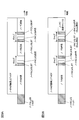
- FIG. 5A and 5B are diagrams illustrating an example of the operation of a plurality of nodes in COT sharing.
- FIG. 6 is a diagram illustrating an example of an operation of a plurality of nodes in COT sharing according to the present embodiment.
- 7A and 7B are diagrams illustrating an example of the operation of a plurality of nodes in COT sharing according to the present embodiment.
- FIG. 6 is a diagram illustrating an example of an operation of a plurality of nodes in COT sharing according to the present embodiment.
- 9A and 9B are diagrams showing an example of the operation of a plurality of nodes in COT sharing according to the present embodiment.
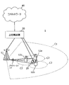
- 1 is a diagram illustrating an example of a schematic configuration of a wireless communication system according to the present embodiment.
- FIG. 3 is a diagram illustrating an example of a functional configuration of a base station according to the present embodiment.
- FIG. 3 is a diagram illustrating an example of a functional configuration of a baseband signal processing unit of a base station.
- FIG. 3 is a diagram illustrating an example of a functional configuration of a user terminal according to the present embodiment.
- FIG. 3 is a diagram illustrating an example of a functional configuration of a baseband signal processing unit of a user terminal. It is a figure showing an example of hardware constitutions of a base station and a user terminal concerning one embodiment of the present invention.
- CSMA / CA Carrier Sense Multiple Access / Collision Avoidance
- Fig. 1 is a diagram showing an example of CSMA / CA.
- the terminal C data transmitting side
- the terminal C checks a signal on the communication medium (carrier sense), and does not immediately start data transmission even if it determines that there is no signal, and waits for a random time. And then send the data.
- This waiting time is called DIFS (Distributed ⁇ Inter ⁇ Frame ⁇ Space).
- the access point B data receiving side
- ACK acknowledgment
- ACK acknowledgement
- ACK acknowledgement
- ACK acknowledgement
- ACK acknowledgement
- ACK can be transmitted only by waiting for a shorter time (Short @ IFS (SIFS)) than DIFS.
- Terminal C (data transmitting side) repeats retransmission until ACK is received. Therefore, the access method shown in FIG. 1 is also called CSMA / CA @ with @ ACK.
- Terminal A (data transmission side) waits for transmission because another terminal (terminal C) is transmitting a signal when examining a signal on the communication medium. After the ongoing transmission operation is completed, that is, after receiving the ACK, the data transmission starts after the elapse of the DIFS and the back-off period.
- FIG. 2 is a diagram showing an example of data collision by a hidden terminal.
- the radio wave from terminal C does not reach terminal A. Therefore, terminal A cannot recognize that terminal C is transmitting data even if carrier sense is performed.
- terminal A transmits data in this state transmission signals from terminal A and terminal C collide at access point B, and data transmission by terminal C fails. This is called the “hidden terminal problem”.
- RTS / CTS Request @ To @ Send / Clear @ To @ Send
- RTS / CTS Request @ To @ Send / Clear @ To @ Send
- the RTS includes time required for data transmission
- the CTS includes time during which data transmission is permitted. Therefore, other terminals that have received the RTS / CTS do not perform a transmission operation during that period, thereby avoiding collision of transmission signals.
- This period is called a transmission prohibition period (Network ⁇ Allocation ⁇ Vector (NAV)).
- An access method using RTS / CTS is also called CSMA / CA @ with @ RTS / CTS.
- FIG. 3 is a diagram showing an example of CSMA / CA ⁇ with ⁇ RTS / CTS.
- the terminal C data transmission side
- the access point B data receiving side
- the terminal C that has received the CTS transmits a CTS after a waiting time (SIFS).
- the terminal C that has received the CTS transmits data after a waiting time (SIFS).
- the access point B receiving the data returns an ACK after a waiting time (SIFS).
- All terminals in the radio wave range of the terminal C and the access point B are notified by RTS / CTS that communication will be performed.
- Other terminals that have detected RTS / CTS wait for transmission during the transmission prohibition period (NAV), so that they do not interfere with data transmission.
- NAV transmission prohibition period
- the RTS transmitted by the terminal C does not reach the terminal A.
- the terminal A recognizes that communication is performed, and waits for transmission. Therefore, the hidden terminal problem is avoided.
- FIG. 4 is a diagram showing an example of an RTS / CTS type access method in a future LAA system.
- the data transmitting side transmitting device
- the data receiving side receives this RTS and transmits CTS as transmission permission.
- the RTS transmitted by the transmitting device may be a message corresponding to the RTS.
- the CTS received by the transmitting device may be a message corresponding to the CTS.
- both the RTS and the CTS may be transmitted on an unlicensed band carrier.
- the RTS and CTS may be transmitted (omni transmission) to the entire cell of the unlicensed CC, or may be transmitted by beamforming in a predetermined direction.
- Both or one of RTS and CTS may be a format conforming to the RTS of the Wi-Fi system or IEEE 802.11, or a format unique to the LAA system.
- the carrier of the unlicensed band may be called an unlicensed carrier, unlicensed CC, LAA @ SCell (Secondary @ Cell), or the like.
- one of RTS and CTS may be transmitted on an unlicensed band carrier, and the other may be transmitted on a licensed band carrier.
- an unlicensed CC of TDD Time Division Duplex, unpaired spectrum
- Listening for example, LBT
- the listening may be omitted or the listening may be short.
- the carrier transmitting the RTS and CTS may be switched dynamically or quasi-statically.
- ⁇ COT sharing> In a future LAA system, a time of a transmission opportunity (Transmission Opportunity (TxOP)) acquired by a base station (gNB) or a user terminal, that is, a channel occupancy period (Channel Occupancy Time (COT)) is distributed (share) to a plurality of nodes. That is being considered.
- the node may be either a user terminal or a base station, or may be a node of another system.
- one-to-one communication of downlink and uplink can be assumed.
- one-to-one communication between node A and node B can be assumed.
- one-to-many communication of downlink and uplink may be assumed.
- FIG. 5 is a diagram illustrating an example of COT sharing in an unlicensed CC. If the node A performs LBT on the unlicensed CC and the LBT result is idle, the node A acquires a transmission opportunity (TxOP) having a COT time length. In this case, the node A performs data transmission in the unlicensed CC.
- the LBT performed immediately before transmission opportunity (TxOP) acquisition is also referred to as an initial LBT (Initial @ LBT (I-LBT)).
- I-LBT Initial @ LBT
- the remaining period of the transmission by the node A may be distributed to other nodes that can receive the signal from the node A.
- a transmission blank period occurs.
- the gap length is 16 [ ⁇ s] or less (or less than 16 [ ⁇ s])
- no-LBT transmission that does not require LBT before transmission may be allowed within the transmission period (TxOP).
- TxOP transmission period
- LBT transmission refers to data transmission that requires an LBT before transmission and that transmits data when the LBT result is idle. Even when the gap length is 16 [ ⁇ s] or less, LBT transmission may be performed within the transmission period (TxOP).
- TxOP transmission period
- node A is a base station and node B and node C are user terminals
- downlink control information indicating scheduling (assignment) of data transmission of node B and node C is transmitted. May be sent.
- information indicating the scheduling of data transmission by the nodes A, B, and C may be transmitted before the transmission opportunity (TxOP).
- the gap length is 16 [ ⁇ s] or less.
- the gap length is larger than 16 [ ⁇ s].
- Category 1 Transmit without performing LBT.
- Category 2 Carrier sensing is performed at a fixed sensing time before transmission, and transmission is performed when a channel is free.
- Category 3 Before transmission, randomly generate a value (random backoff) from within a predetermined range, repeat carrier sense in a fixed sensing slot time, and confirm that the channel is vacant over the slot of the value. If sent.
- Category 4 Before transmission, a value (random back-off) is randomly generated from within a predetermined range, carrier sense is repeatedly performed in a fixed sensing slot time, and it can be confirmed that a channel is vacant over the slot of the value. If sent.
- the range of the random backoff value (contention window size) changes according to the communication failure situation due to collision with communication of another system.
- an LBT in a receiver-assisted LBT or an LTE-LAA may be performed.
- the LTE of LTE @ LAA is category 4.
- the LBT performed within the transmission period (TxOP) may be a one-shot LBT for performing carrier sensing for a short fixed time, or may be an LBT in LTE LAA.
- One-shot LBT is also called short LBT. If the cap is 16 [ ⁇ s] or less, no-LBT transmission may be performed.
- the channel occupation period (COT) is distributed among a plurality of (for example, three or more) nodes.
- a node for example, node A
- TxOP transmission opportunity
- I-LBT initial LBT
- one of the nodes sharing the COT for example, node B
- the present inventors have found a means for reducing loss of radio resources due to signal collision and improving radio resource utilization efficiency in COT sharing.
- the unlicensed CC includes a carrier (cell, CC) in the first frequency band, a carrier (cell, CC) in the unlicensed band, an LAA @ SCell, a LAA cell, a secondary cell (SCell), and the like. It may be read as.
- the licensed CC may be read as a carrier (cell, CC) in the second frequency band, a carrier (cell, CC) in the licensed band, PCell (Primary @ Cell), SCell, or the like.
- the unlicensed CC may be LTE-based or NR-based (NRlicunlicensed CC).
- the licensed CC may be LTE-based or NR-based.
- the unlicensed CC and the licensed CC may be subjected to carrier aggregation (CA) or dual connectivity (DC) in either LTE or NR system ( Stand-alone), carrier aggregation (CA) or dual connectivity (DC) between LTE and NR systems (non-stand-alone).
- CA carrier aggregation
- DC dual connectivity
- NR-U Unlicensed
- the LAA system may be compliant (supported) with a first wireless communication standard (eg, NR, LTE, etc.).
- a first wireless communication standard eg, NR, LTE, etc.
- the coexistence system may be a system that receives interference from the LAA system or may be a system that gives interference to the LAA system.
- the coexistence system may support RTS and CTS, or equivalent transmission request and ready signals.
- a device (node A) that performs the initial LBT (I-LBT) may be called a transmitting device.
- a device (node B or node C) that receives data transmitted by another device at a transmission opportunity (TxOP) acquired by another device (node A) may be referred to as a receiving device.
- the data transmitted by the transmitting device and the receiving device may include at least one of user data and control information.
- the channel occupation period (COT) is distributed among three or more nodes (for example, node A, node B, and node C).
- the node A is a node that acquires a transmission opportunity (TxOP) by the initial LBT (I-LBT), becomes a data transmitting side in the first period of the transmission opportunity (TxOP), and acquires the remaining transmission opportunity (TxOP). It becomes the data receiving side in the period.
- the nodes B and C become receivers of the data transmitted by the node A in the first period of the transmission opportunity (TxOP) acquired by the node A, and become data transmitters in the remaining period of the transmission opportunity (TxOP).
- the node on the side performs carrier sense (for example, LBT, short LBT or LTE LAA LBT) in a blank period (gap) for switching the transmission source within the transmission opportunity (TxOP), and transmits the result to the data transmission side.
- carrier sense for example, LBT, short LBT or LTE LAA LBT
- the data transmitting node may cancel (drop) the remaining data transmission in the transmission opportunity (TxOP).
- the time of carrier sense (for example, short LBT) performed in the blank period (gap) is shorter than the cap time.
- the time of the short LBT may be shorter than the time of the initial LBT (I-LBT).
- the node on the data transmission side that is notified of the result of the carrier sense can transmit data without performing LBT if the gap length allows no-LBT transmission (for example, 16 [ ⁇ s] or less). Transmission may be started.
- the result of the carrier sense (busy or idle) may be notified by a preamble pattern that does not require demodulation.
- the node may perform the operation shown in any of the following methods 1 to 4.
- 8 and 7 are diagrams illustrating an example of the operation of a plurality of nodes in COT sharing.
- Method 1 A node that has acquired a transmission opportunity (TxOP) by the initial LBT (I-LBT), and becomes a data transmitting side in the first period of the transmission opportunity (TxOP), and communicates with the data receiving side in the remaining period of the transmission opportunity (TxOP).
- the other node for example, node A
- FIGS. 8, 7A and 7B show an example of the operation of a plurality of nodes in COT sharing according to method 1-1.
- the node A that has acquired the transmission opportunity (TxOP) by the initial LBT (I-LBT) performs the LBT in the subsequent blank period (gap) when the data transmission within the transmission opportunity (TxOP) ends.
- node B and node C that share the transmission opportunity (TxOP) obtained by the node A by the COT cancel the data transmission when receiving the busy notification frame even if the data transmission is allocated. (Drop).
- node A when the LBT result is idle (idle detection), node A does not transmit information (notification frame) indicating the result of the LBT. That is, the node A does not transmit information indicating idle (idle notification frame) or information indicating busy (busy notification frame).
- Another node for example, node B that shares the transmission opportunity (TxOP) acquired by the node A with the COT after the data transmission by the node A is completed does not receive the busy notification frame in the unlicensed CC.
- the assigned data is transmitted within TxOP).
- the node A performs the LBT during the subsequent blank period (gap).
- the node A does not transmit information (notification frame) indicating the result of the LBT.
- Another node for example, node C that shares the transmission opportunity (TxOP) obtained by the node A with the COT sharing, when the busy notification frame is not received in the unlicensed CC after the end of data transmission by the node B, the transmission opportunity ( The assigned data is transmitted within TxOP).
- the node A transmits a busy notification frame in the unlicensed CC as shown in FIG. 7B.
- the node C that shares the transmission opportunity (TxOP) obtained by the node A with the COT sharing receives the busy notification frame, the node cancels the data transmission even if the data transmission is assigned ( Drop).
- Node B and Node C may respectively perform LBT.
- the gap length allows no-LBT transmission (for example, 16 [ ⁇ s] or less)
- node B and node C may each perform data transmission without LBT.
- Method 2 A node that has acquired a transmission opportunity (TxOP) by the initial LBT (I-LBT), and becomes a data transmitting side in the first period of the transmission opportunity (TxOP), and communicates with the data receiving side in the remaining period of the transmission opportunity (TxOP).
- the other node (for example, node A) performs the LBT within a blank period (gap) within the transmission opportunity (TxOP).
- the node may transmit information (notification frame) indicating the LBT result in the licensed CC.
- the information indicating the LBT result may be information indicating idle (idle notification frame) or information indicating busy (busy notification frame).
- FIGS. 8, 9A, and 9B show an example of the operation of multiple nodes in COT sharing according to method 1-2.
- the node A that has acquired the transmission opportunity (TxOP) by the initial LBT (I-LBT) performs the LBT in the subsequent blank period (gap) when the data transmission within the transmission opportunity (TxOP) ends.
- Node A transmits information (notification frame) indicating the result of the LBT in the licensed CC.
- the node A transmits a busy detection frame in the licensed CC.
- node B and node C that share the transmission opportunity (TxOP) obtained by the node A by the COT cancel the data transmission when receiving the busy notification frame even if the data transmission is allocated. (Drop).
- the node A transmits an idle detection frame in the licensed CC.
- node B Upon receiving the idle notification frame, another node (for example, node B) that shares the transmission opportunity (TxOP) acquired by the node A with the COT shares the data allocated in the transmission opportunity (TxOP) of the unlicensed CC. Send.
- TxOP transmission opportunity
- the node A performs the LBT during the subsequent blank period (gap).
- the node A transmits an idle notification frame in the licensed CC as shown in FIG. 9A.
- another node eg, node C
- TxOP transmission opportunity
- the node A transmits a busy notification frame in the licensed CC.
- another node for example, the node C that shares the transmission opportunity (TxOP) obtained by the node A with the COT sharing receives the busy notification frame, the node cancels the data transmission even if the data transmission is assigned ( Drop).
- nodes B and C that share the transmission opportunity (TxOP) acquired by the node A by the COT, if the notification frame is not received in the licensed CC after the data transmission by the node A ends, the transmission opportunity (TxOP).
- the data transmission allocated in the parentheses may be canceled.
- the node B and the node C may perform the data transmission allocated within the transmission opportunity (TxOP).
- Node B and Node C may respectively perform LBT.
- the gap length allows no-LBT transmission (for example, 16 [ ⁇ s] or less)
- node B and node C may each perform data transmission without LBT.
- the other node (for example, node A) performs LBT within a blank period (gap) within the transmission opportunity (TxOP).
- the node may transmit information (notification frame) indicating the LBT result in the unlicensed CC.
- the information indicating the LBT result may be information indicating idle (idle notification frame) or information indicating busy (busy notification frame).
- FIGS. 8, 9A and 9B show an example of the operation of a plurality of nodes in the COT sharing according to the method 1-3.
- the node A that has acquired the transmission opportunity (TxOP) by the initial LBT (I-LBT) performs the LBT in the subsequent blank period (gap) when the data transmission within the transmission opportunity (TxOP) ends.
- Node A transmits information (notification frame) indicating the result of the LBT in the unlicensed CC.
- the node A transmits a busy detection frame in the unlicensed CC.
- node B and node C that share the transmission opportunity (TxOP) obtained by the node A by the COT cancel the data transmission when receiving the busy notification frame even if the data transmission is allocated. (Drop).
- node A transmits an idle detection frame in the unlicensed CC.
- node B Upon receiving the idle notification frame, another node (for example, node B) that shares the transmission opportunity (TxOP) acquired by the node A with the COT shares the data allocated in the transmission opportunity (TxOP) of the unlicensed CC. Send.
- TxOP transmission opportunity
- the node A performs the LBT during the subsequent blank period (gap).
- the node A transmits an idle notification frame in the unlicensed CC.
- another node eg, node C
- TxOP transmission opportunity
- the node A transmits a busy notification frame in the unlicensed CC.
- the node C that shares the transmission opportunity (TxOP) obtained by the node A with the COT sharing receives the busy notification frame, the node cancels the data transmission even if the data transmission is assigned ( Drop).
- the other nodes that share the transmission opportunity (TxOP) acquired by the node A by the COT, when the notification frame is not received in the unlicensed CC after the data transmission by the node A ends, the transmission opportunity ( The transmission of data allocated within TxOP) may be canceled.
- the node B and the node C may perform the data transmission allocated within the transmission opportunity (TxOP).
- Node B and Node C may respectively perform LBT.
- the gap length allows no-LBT transmission (for example, 16 [ ⁇ s] or less)
- node B and node C may each perform data transmission without LBT.
- Method 4 A node that has acquired a transmission opportunity (TxOP) by the initial LBT (I-LBT), and becomes a data transmitting side in the first period of the transmission opportunity (TxOP), and communicates with the data receiving side in the remaining period of the transmission opportunity (TxOP).
- the other node for example, node A
- the node may notify the information indicating busy (for example, a busy notification frame) in the licensed CC.
- FIGS. 8, 7A and 7B show an example of the operation of a plurality of nodes in COT sharing according to Method 1-4.
- the node A that has acquired the transmission opportunity (TxOP) by the initial LBT (I-LBT) performs the LBT when data transmission within the transmission opportunity (TxOP) ends.
- node B and node C that COT share the transmission opportunity (TxOP) acquired by node A, upon receiving the busy notification frame, cancel the data transmission even if data transmission is allocated. (Drop).
- node A when the LBT result is idle (idle detection), node A does not transmit information (notification frame) indicating the result of the LBT. That is, the node A does not transmit information indicating idle (idle notification frame) or information indicating busy (busy notification frame).
- Another node for example, node B that shares the transmission opportunity (TxOP) acquired by the node A with the COT after receiving data by the node A does not receive a busy notification frame in the unlicensed CC after the node A completes data transmission.
- the assigned data is transmitted within TxOP).
- the node A performs the LBT during the subsequent blank period (gap).
- the node A does not transmit information (notification frame) indicating the result of the LBT.
- Another node for example, node C that shares the transmission opportunity (TxOP) obtained by the node A with the COT sharing, when the busy notification frame is not received in the unlicensed CC after the end of data transmission by the node B, the transmission opportunity ( The assigned data is transmitted within TxOP).
- the node A transmits a busy notification frame in the licensed CC as shown in FIG. 7B.
- the node C that shares the transmission opportunity (TxOP) obtained by the node A with the COT sharing receives the busy notification frame, the node cancels the data transmission even if the data transmission is assigned ( Drop).
- Node B and Node C may respectively perform LBT.
- the gap length allows no-LBT transmission (for example, 16 [ ⁇ s] or less)
- node B and node C may each perform data transmission without LBT.
- the busy notification frame may be information instructing cancellation of data transmission, information indicating changed data transmission allocation, or information indicating data transmission deactivation (deactivation, release). It may be.
- the idle notification frame may be information indicating assignment of data transmission by another node, or information indicating activation of data transmission.
- the busy notification frame or the idle notification frame includes a downlink control channel (for example, Physical Downlink Control Channel (PDCCH) or Downlink Control Information (DCI)), a scheduled downlink channel (for example, Physical Downlink Shared Channel (PDSCH)), and a user terminal.
- a downlink control channel for example, Physical Downlink Control Channel (PDCCH) or Downlink Control Information (DCI)
- PDSCH Physical Downlink Shared Channel
- Individual uplink channels eg, Physical Uplink Control Channel (PUCCH)
- uplink channels scheduled by dynamic grants eg, Physical Uplink Shared Channel (PUSCH)
- uplink channels not scheduled by dynamic grants eg, Grant-free PUSCH.
- the busy notification frame or the idle notification frame may include an identifier of a transmission source (for example, a MAC (Media Access Control) address, a user terminal (UE) ID or a cell ID), or an identifier of a transmission destination (for example, , MAC address, user terminal (UE) ID or cell ID), and may include information (eg, time resource) related to data transmission allocation.
- a transmission source for example, a MAC (Media Access Control) address, a user terminal (UE) ID or a cell ID
- a transmission destination for example, , MAC address, user terminal (UE) ID or cell ID
- information eg, time resource
- the transmission timing of the signal for notifying busy or idle is determined by another node (eg, the node sharing COT during transmission of data by the node (eg, node A) that has acquired the transmission opportunity (TxOP) by the initial LBT (I-LBT)).
- another node that performs COT sharing may perform a detection operation of a signal that notifies busy or idle only during a necessary time period.
- radio communication method According to the radio communication method according to the present embodiment, loss of radio resources due to signal collision can be reduced and radio resource utilization efficiency can be improved.
- Wireless communication system Wireless communication system
- the configuration of the wireless communication system according to the present embodiment will be described.
- the wireless communication method according to the above embodiment is applied.
- FIG. 10 is a diagram showing an example of a schematic configuration of the wireless communication system according to the present embodiment.
- a carrier aggregation Carrier Aggregation (CA)
- CA Carrier Aggregation
- CCs Component Carriers
- DC Dual Connectivity
- the wireless communication system 1 may be called SUPER @ 3G, LTE-A (LTE-Advanced), IMT-Advanced, 4G, 5G, FRA (Future Radio Access), NR (New Radio), or the like.
- the wireless communication system 1 may support dual connectivity (Multi-RAT DC (MR-DC)) between a plurality of RATs (Radio Access Technology).
- MR-DC Multi-RAT DC
- the LTE (E-UTRA) base station (eNB) serves as a master node
- the NR base station (gNB) serves as a secondary node.
- Dual connectivity E-UTRA-NR @ DC (EN) -DC)
- dual connectivity NR-E-UTRA @ DC (NE-DC)
- the wireless communication system 1 includes a base station 11 forming a macro cell C1, and base stations 12a to 12c arranged in the macro cell C1 and forming small cells C2 smaller than the macro cell C1.
- User terminals 20 are arranged in the macro cell C1 and each small cell C2.
- a configuration in which different numerology is applied between cells may be adopted. Numerology refers to a signal design in a certain RAT and a set of communication parameters that characterize the RAT design.
- the user terminal 20 can be connected to both the base station 11 and the base station 12. It is assumed that the user terminal 20 simultaneously uses the macro cell C1 and the small cell C2 using different frequencies by carrier aggregation (CA) or dual connectivity (DC).
- the user terminal 20 can apply carrier aggregation (CA) or dual connectivity (DC) using a plurality of cells (CCs) (for example, two or more CCs).
- CCs cells
- the user terminal can use the licensed band CC and the unlicensed band CC as a plurality of cells.
- a configuration may be employed in which a TDD carrier to which the shortened TTI is applied is included in any of the plurality of cells.
- Communication between the user terminal 20 and the base station 11 can be performed using a carrier having a relatively low frequency band (for example, 2 GHz) and a narrow bandwidth (existing carrier, called Legacy carrier).
- a carrier having a relatively high frequency band for example, 3.5 GHz, 5 GHz, 30 to 70 GHz, or the like
- the same carrier as that between may be used.
- the configuration of the frequency band used by each base station is not limited to this.
- a wired connection for example, an optical fiber compliant with CPRI (Common Public Radio Interface), an X2 interface, or the like
- a wireless connection is used between the base station 11 and the base station 12 (or between the two base stations 12). It can be.
- the base station 11 and each base station 12 are connected to the upper station apparatus 30, respectively, and are connected to the core network 40 via the upper station apparatus 30.
- the upper station device 30 includes, for example, an access gateway device, a radio network controller (RNC), a mobility management entity (MME), and the like, but is not limited thereto.
- RNC radio network controller
- MME mobility management entity
- Each base station 12 may be connected to the upper station apparatus 30 via the base station 11.
- the base station 11 is a base station having relatively wide coverage and may be called a macro base station, an aggregation node, an eNB (eNodeB), a transmission / reception point, or the like.
- the base station 12 is a base station having local coverage, and is called a small base station, a micro base station, a pico base station, a femto base station, a HeNB (Home eNodeB), an RRH (Remote Radio Head), a transmission / reception point, or the like. It may be.
- the base stations 11 and 12 are not distinguished, they are collectively referred to as a base station 10.
- Each user terminal 20 is a terminal corresponding to various communication systems such as LTE and LTE-A, and may include not only mobile communication terminals but also fixed communication terminals.
- OFDMA orthogonal frequency division multiple access
- SC-FDMA single carrier-frequency division multiple access
- OFDMA is a multicarrier transmission scheme in which a frequency band is divided into a plurality of narrow frequency bands (subcarriers), and data is mapped to each subcarrier to perform communication.
- SC-FDMA is a single-carrier transmission scheme that divides a system bandwidth into bands each consisting of one or a continuous resource block for each terminal, and reduces interference between terminals by using different bands for a plurality of terminals. is there.
- the uplink and downlink radio access schemes are not limited to these combinations, and OFDMA may be used in UL.
- a downlink data channel also referred to as a Physical Downlink Shared Channel (PDSCH), a downlink shared channel, etc.
- PDSCH Physical Downlink Shared Channel
- PBCH Physical Broadcast Channel
- L1 Physical Broadcast Channel
- PBCH Physical Broadcast Channel
- L2 control channel or the like is used.
- the PDSCH transmits user data, higher layer control information, SIB (System Information Block), and the like.
- SIB System Information Block
- MIB Master Information Block
- the L1 / L2 control channels include downlink control channels (Physical Downlink Control Channel (PDCCH), Enhanced Physical Downlink Control Channel (EPDCCH)), PCFICH (Physical Control Format Indicator Channel), PHICH (Physical Hybrid-ARQ Indicator Channel), and the like. .
- Downlink control information (Downlink Control Information (DCI)) including PDSCH and PUSCH scheduling information is transmitted by the PDCCH.
- the number of OFDM symbols used for PDCCH is transmitted by PCFICH.
- the PHICH transmits HARQ delivery confirmation information (ACK / NACK) for the PUSCH.
- the EPDCCH is frequency-division multiplexed with the PDSCH (Downlink Shared Data Channel), and is used for transmission of DCI and the like like the PDCCH.
- an uplink data channel Physical Uplink Shared Channel (PUSCH), also referred to as an uplink shared channel) shared by each user terminal 20, an uplink control channel (Physical Uplink Control Channel (PUCCH)).
- a random access channel Physical Random Access Channel (PRACH)) or the like.
- PUSCH is used to transmit user data and higher layer control information.
- Uplink control information Uplink Control Information (UCI)) including at least one of acknowledgment information (ACK / NACK) and radio quality information (CQI) is transmitted by PUSCH or PUCCH.
- the PRACH transmits a random access preamble for establishing a connection with a cell.
- FIG. 11 is a diagram showing an example of the entire configuration of the base station according to the present embodiment.
- the base station 10 includes a plurality of transmitting / receiving antennas 101, an amplifier unit 102, a transmitting / receiving unit 103, a baseband signal processing unit 104, a call processing unit 105, and a transmission path interface 106.
- the transmitting / receiving antenna 101, the amplifier unit 102, and the transmitting / receiving unit 103 may be configured to include at least one each.
- the base station 10 is a transmitting device for downlink data, and may be a receiving device for uplink data.
- ⁇ ⁇ Downlink data transmitted from the base station 10 to the user terminal 20 is input from the higher station apparatus 30 to the baseband signal processing unit 104 via the transmission path interface 106.
- the baseband signal processing unit 104 regarding downlink data, processing of a PDCP (Packet Data Convergence Protocol) layer, division / combination of user data, transmission processing of an RLC layer such as RLC (Radio Link Control) retransmission control, MAC (Medium Access) Control) Transmission processing such as retransmission control (for example, HARQ transmission processing), scheduling, transmission format selection, channel coding, inverse fast Fourier transform (Inverse Fast Fourier Transform (IFFT)) processing, and precoding processing are performed, and transmission / reception is performed. It is transferred to the unit 103.
- the downlink control signal is also subjected to transmission processing such as channel coding and inverse fast Fourier transform, and is transferred to the transmission / reception unit 103.
- the transmission / reception section 103 converts the baseband signal pre-coded and output from the baseband signal processing section 104 for each antenna into a radio frequency band, and transmits the radio frequency band.
- the radio frequency signal frequency-converted by the transmitting / receiving section 103 is amplified by the amplifier section 102 and transmitted from the transmitting / receiving antenna 101.
- the transmission / reception unit 103 can be configured by a transmitter / receiver, a transmission / reception circuit, or a transmission / reception device described based on common recognition in the technical field according to the present invention.
- the transmission / reception unit 103 may be configured as an integrated transmission / reception unit, or may be configured from a transmission unit and a reception unit.
- the radio frequency signal received by the transmission / reception antenna 101 is amplified by the amplifier unit 102.
- the transmitting / receiving section 103 receives the upstream signal amplified by the amplifier section 102.
- Transmitting / receiving section 103 frequency-converts the received signal into a baseband signal and outputs the baseband signal to baseband signal processing section 104.
- the baseband signal processing unit 104 performs fast Fourier transform (Fast Fourier Transform (FFT)) processing, inverse discrete Fourier transform (Inverse Discrete Fourier Transform (IDFT)) processing on user data included in the input uplink signal, Error correction decoding, reception processing of MAC retransmission control, reception processing of the RLC layer and PDCP layer are performed, and the data is transferred to the upper station apparatus 30 via the transmission path interface 106.
- the call processing unit 105 performs call processing such as setting and release of a communication channel, state management of the base station 10, and management of radio resources.
- the transmission path interface 106 transmits and receives signals to and from the higher-level station device 30 via a predetermined interface.
- the transmission path interface 106 may transmit and receive signals (backhaul signaling) to and from another base station 10 via an interface between base stations (for example, an optical fiber compliant with CPRI (Common Public Radio Interface), an X2 interface). .
- CPRI Common Public Radio Interface
- X2 interface X2 interface
- the transmission / reception unit 103 may further include an analog beamforming unit that performs analog beamforming.
- the analog beam forming unit includes an analog beam forming circuit (for example, a phase shifter, a phase shift circuit) or an analog beam forming device (for example, a phase shifter) described based on common recognition in the technical field according to the present invention. can do.
- the transmission / reception antenna 101 can be configured by, for example, an array antenna.
- the transmission / reception unit 103 is configured so that a single BF and a multi BF can be applied.
- Transceiving section 103 may transmit a signal using a transmission beam or receive a signal using a reception beam.
- the transmission / reception unit 103 may transmit and receive a signal using a predetermined beam determined by the control unit 301.
- the transmitting / receiving section 103 includes a downlink signal (for example, a downlink control signal (downlink control channel), a downlink data signal (downlink data channel, downlink shared channel), a downlink reference signal (DM-RS, CSI-RS, etc.), a discovery signal, a synchronization signal, Signals, broadcast signals, etc.).
- the transmitting / receiving section 103 receives an uplink signal (eg, an uplink control signal (uplink control channel), an uplink data signal (uplink data channel, uplink shared channel), an uplink reference signal, and the like).
- the transmission / reception unit 103 may transmit a signal based on a result of listening to an unlicensed CC (first frequency band).
- the signal includes a data signal and an RTS (transmission request signal).
- the transmission / reception section 103 may transmit the signal in one of the unlicensed CC (first frequency band) and the licensed CC (second frequency band).
- the transmission / reception unit 103 may receive a response signal to the signal.
- the response signal includes ACK (acknowledge) and CTS (response signal to the transmission request signal).
- the transmission / reception unit 103 may receive the response signal in one of the unlicensed CC (first frequency band) and the licensed CC (second frequency band).
- the transmitting and receiving unit 103 may transmit or receive a result of listening to the unlicensed CC (first frequency band).
- Transceiving section 103 may transmit the first signal (eg, data signal) at a transmission opportunity (TxOP) based on the result of the first listening (eg, initial LBT (I-LBT)).
- the transmission / reception unit 103 is information indicating the result of the second listening (for example, LBT) performed in each blank period (gap) in the period after the transmission of the first signal in the transmission opportunity (TxOP) based on the result of the first listening.
- a notification frame, a busy notification frame, an idle notification frame may be transmitted.
- the transmission unit and the reception unit of the present invention are configured by both or one of the transmission / reception unit 103 and the transmission line interface 106.
- FIG. 12 is a diagram showing an example of a functional configuration of the base station according to the present embodiment.
- FIG. 2 mainly shows functional blocks of characteristic portions in the present embodiment, and it is assumed that the base station 10 also has other functional blocks necessary for wireless communication.
- the baseband signal processing unit 104 includes at least a control unit 301, a transmission signal generation unit 302, a mapping unit 303, a reception signal processing unit 304, and a measurement unit 305.
- the control unit 301 controls the entire base station 10.
- the control unit 301 can be configured by a controller, a control circuit, or a control device described based on common recognition in the technical field according to the present invention.
- the control unit 301 controls, for example, generation of a signal by the transmission signal generation unit 302 and allocation of a signal by the mapping unit 303.
- the control unit 301 controls signal reception processing by the reception signal processing unit 304 and signal measurement by the measurement unit 305.
- Control section 301 controls scheduling of downlink signals and uplink signals (for example, resource allocation). Specifically, control section 301 transmits and generates DCI (DL assignment, DL grant) including scheduling information of the downlink data channel and DCI (UL grant) including scheduling information of the uplink data channel. It controls the signal generation unit 302, the mapping unit 303, and the transmission / reception unit 103.
- DCI DL assignment, DL grant
- UL grant DCI
- the control unit 301 may control signal transmission or reception in an unlicensed CC (first frequency band) or a licensed CC (second frequency band).
- Control section 301 transmits each blank in a period after transmission of a first signal (eg, a data signal by node A) in a transmission opportunity (TxOP) based on a result of the first listening (eg, initial LBT (I-LBT)). Control may be performed to notify (transmit) information (for example, a notification frame, a busy notification frame, and an idle notification frame) indicating the result of the second listening (for example, LBT) performed during the period (gap).
- a first signal eg, a data signal by node A
- TxOP transmission opportunity
- Control may be performed to notify (transmit) information (for example, a notification frame, a busy notification frame, and an idle notification frame) indicating the result of the second listening (for example, LBT) performed during the period (gap).
- the control unit 301 may perform control to notify the transmission timing of information indicating the result of the second listening (for example, LBT) when transmitting the first signal (for example, the data signal by the node A).
- the control unit 301 may control to transmit information indicating the result of the second listening only when the result of the second listening (for example, LBT) is busy.
- the transmission signal generation unit 302 generates a downlink signal (a downlink control channel, a downlink data channel, a downlink reference signal such as a DM-RS, etc.) based on an instruction from the control unit 301, and outputs the downlink signal to the mapping unit 303.
- the transmission signal generation unit 302 can be configured from a signal generator, a signal generation circuit, or a signal generation device described based on common recognition in the technical field according to the present invention.
- Mapping section 303 maps the downlink signal generated by transmission signal generation section 302 to a predetermined radio resource based on an instruction from control section 301, and outputs the result to transmission / reception section 103.
- the mapping unit 303 can be configured by a mapper, a mapping circuit, or a mapping device described based on common recognition in the technical field according to the present invention.
- Reception signal processing section 304 performs reception processing (for example, demapping, demodulation, decoding, etc.) on the reception signal input from transmission / reception section 103.
- the received signal is an uplink signal (uplink control channel, uplink data channel, uplink reference signal, etc.) transmitted from the user terminal 20.
- the reception signal processing unit 304 can be configured from a signal processor, a signal processing circuit, or a signal processing device described based on common recognition in the technical field according to the present invention.
- the reception signal processing unit 304 outputs the information decoded by the reception processing to the control unit 301.
- the reception processing unit 304 outputs at least one of a preamble, control information, and UL data to the control unit 301.
- reception signal processing section 304 outputs the reception signal and the signal after the reception processing to measurement section 305.
- the measurement unit 305 performs measurement on the received signal.
- the measurement unit 305 can be constituted by a measurement device, a measurement circuit, or a measurement device described based on common recognition in the technical field according to the present invention.
- the measurement unit 305 may measure, for example, the received power (for example, Reference Signal Received Power (RSRP)) of the received signal, the reception quality (for example, Reference Signal Received Quality (RSRQ)), the channel state, and the like.
- the measurement result may be output to the control unit 301.
- FIG. 13 is a diagram showing an example of the overall configuration of the user terminal according to the present embodiment.
- the user terminal 20 includes a plurality of transmitting / receiving antennas 201, an amplifier unit 202, a transmitting / receiving unit 203, a baseband signal processing unit 204, and an application unit 205.
- the transmitting / receiving antenna 201, the amplifier unit 202, and the transmitting / receiving unit 203 may be configured to include at least one each.
- the user terminal 20 is a receiving device for downlink data, and may be a transmitting device for uplink data.
- the radio frequency signal received by the transmitting / receiving antenna 201 is amplified by the amplifier unit 202.
- the transmission / reception unit 203 receives the downlink signal amplified by the amplifier unit 202.
- the transmitting / receiving section 203 converts the frequency of the received signal into a baseband signal and outputs the baseband signal to the baseband signal processing section 204.
- the transmission / reception unit 203 can be configured by a transmitter / receiver, a transmission / reception circuit, or a transmission / reception device described based on common recognition in the technical field according to the present invention.
- the transmission / reception unit 203 may be configured as an integrated transmission / reception unit, or may be configured from a transmission unit and a reception unit.
- the baseband signal processing unit 204 performs FFT processing, error correction decoding, reception processing for retransmission control, and the like on the input baseband signal.
- the downlink data is transferred to the application unit 205.
- the application unit 205 performs processing related to a layer higher than the physical layer and the MAC layer. Of the downlink data, system information and higher layer control information are also transferred to the application unit 205.
- Uplink user data is input from the application unit 205 to the baseband signal processing unit 204.
- the baseband signal processing unit 204 performs retransmission control transmission processing (eg, HARQ transmission processing), channel coding, precoding, discrete Fourier transform (Discrete Fourier Transform (DFT)) processing, IFFT processing, and the like.
- the data is transferred to the transmission / reception unit 203.
- the transmission / reception unit 203 converts the baseband signal output from the baseband signal processing unit 204 into a radio frequency band and transmits the radio frequency band.
- the radio frequency signal frequency-converted by the transmission / reception unit 203 is amplified by the amplifier unit 202 and transmitted from the transmission / reception antenna 201.
- the transmission / reception unit 203 may further include an analog beamforming unit that performs analog beamforming.
- the analog beam forming unit includes an analog beam forming circuit (for example, a phase shifter, a phase shift circuit) or an analog beam forming device (for example, a phase shifter) described based on common recognition in the technical field according to the present invention. can do.
- the transmitting / receiving antenna 201 can be configured by, for example, an array antenna.
- the transmission / reception unit 203 is configured so that single BF and multi BF can be applied.
- the transmission / reception unit 203 may transmit a signal using a transmission beam, or may receive a signal using a reception beam.
- the transmission / reception unit 203 may transmit and receive a signal using a predetermined beam determined by the control unit 401.
- the transmitting / receiving section 203 includes a downlink signal (for example, a downlink control signal (downlink control channel), a downlink data signal (downlink data channel, downlink shared channel), a downlink reference signal (DM-RS, CSI-RS, etc.), a discovery signal, a synchronization signal, Signals, annunciation signals, etc.).
- the transmitting / receiving section 203 transmits an uplink signal (eg, an uplink control signal (uplink control channel), an uplink data signal (uplink data channel, uplink shared channel), an uplink reference signal, and the like).
- the transmission / reception unit 103 may transmit a signal based on a result of listening to an unlicensed CC (first frequency band).
- the signal includes a data signal and an RTS (transmission request signal).
- the transmission / reception section 103 may transmit the signal in one of the unlicensed CC (first frequency band) and the licensed CC (second frequency band).
- the transmission / reception unit 103 may receive a response signal to the signal.
- the response signal includes ACK (acknowledge) and CTS (response signal to the transmission request signal).
- the transmission / reception unit 103 may receive the response signal in one of the unlicensed CC (first frequency band) and the licensed CC (second frequency band).
- the transmitting and receiving unit 103 may transmit or receive a result of listening to the unlicensed CC (first frequency band).
- Transceiving section 103 may transmit the first signal (eg, data signal) at a transmission opportunity (TxOP) based on the result of the first listening (eg, initial LBT (I-LBT)).
- the transmission / reception unit 103 is information indicating the result of the second listening (for example, LBT) performed in each blank period (gap) in the period after the transmission of the first signal in the transmission opportunity (TxOP) based on the result of the first listening.
- a notification frame, a busy notification frame, an idle notification frame may be transmitted.
- FIG. 14 is a diagram showing an example of a functional configuration of the user terminal according to the present embodiment.
- FIG. 2 mainly shows functional blocks of characteristic portions in the present embodiment, and it is assumed that the user terminal 20 also has other functional blocks necessary for wireless communication.
- the baseband signal processing unit 204 included in the user terminal 20 includes at least a control unit 401, a transmission signal generation unit 402, a mapping unit 403, a reception signal processing unit 404, and a measurement unit 405.
- the control unit 401 controls the entire user terminal 20.
- the control unit 401 can be configured by a controller, a control circuit, or a control device described based on common recognition in the technical field according to the present invention.
- the control unit 401 controls, for example, generation of a signal by the transmission signal generation unit 402 and assignment of a signal by the mapping unit 403.
- the control unit 401 controls signal reception processing by the reception signal processing unit 404 and signal measurement by the measurement unit 405.
- the control unit 401 may control signal transmission or reception in an unlicensed CC (first frequency band) or a licensed CC (second frequency band).
- Control unit 401 transmits each blank in a period after transmission of a first signal (for example, a data signal by node A) in a transmission opportunity (TxOP) based on a result of first listening (for example, initial LBT (I-LBT)). Control may be performed to notify (transmit) information (for example, a notification frame, a busy notification frame, and an idle notification frame) indicating the result of the second listening (for example, LBT) performed during the period (gap).
- a first signal for example, a data signal by node A
- TxOP transmission opportunity
- first listening for example, initial LBT (I-LBT)
- Control may be performed to notify (transmit) information (for example, a notification frame, a busy notification frame, and an idle notification frame) indicating the result of the second listening (for example, LBT) performed during the period (gap).
- the control unit 401 may perform control to notify the transmission timing of information indicating the result of the second listening (for example, LBT) when transmitting the first signal (for example, the data signal by the node A).
- the control unit 401 may control to transmit information indicating the result of the second listening only when the result of the second listening (for example, LBT) is busy.
- Transmission signal generation section 402 generates an uplink signal (uplink control channel, uplink data channel, uplink reference signal, etc.) based on an instruction from control section 401, and outputs it to mapping section 403.
- the transmission signal generation unit 402 can be configured from a signal generator, a signal generation circuit, or a signal generation device described based on common recognition in the technical field according to the present invention.
- Transmission signal generation section 402 generates an uplink data channel based on an instruction from control section 401. For example, when the UL grant is included in the downlink control channel notified from base station 10, transmission signal generation section 402 is instructed by control section 401 to generate an uplink data channel.
- Mapping section 403 maps the uplink signal generated by transmission signal generation section 402 to a radio resource based on an instruction from control section 401, and outputs the result to transmission / reception section 203.
- the mapping unit 403 can be composed of a mapper, a mapping circuit, or a mapping device described based on common recognition in the technical field according to the present invention.
- the reception signal processing unit 404 performs reception processing (for example, demapping, demodulation, decoding, and the like) on the reception signal input from the transmission / reception unit 203.
- the received signal is a downlink signal (a downlink control channel, a downlink data channel, a downlink reference signal, etc.) transmitted from the base station 10.
- the reception signal processing unit 404 can be configured by a signal processor, a signal processing circuit, or a signal processing device described based on common recognition in the technical field according to the present invention.
- the reception signal processing unit 404 can constitute a reception unit according to the present invention.
- Reception signal processing section 404 performs blind decoding on the downlink control channel for scheduling transmission and reception of the downlink data channel based on the instruction of control section 401, and performs reception processing of the downlink data channel based on the DCI.
- Received signal processing section 404 estimates a channel gain based on DM-RS or CRS, and demodulates a downlink data channel based on the estimated channel gain.
- the reception signal processing unit 404 outputs the information decoded by the reception processing to the control unit 401.
- the reception signal processing unit 404 outputs, for example, broadcast information, system information, RRC signaling, DCI, and the like to the control unit 401.
- the reception signal processing unit 404 may output the data decoding result to the control unit 401.
- the reception signal processing unit 404 outputs the reception signal and the signal after the reception processing to the measurement unit 405.
- the measuring unit 405 measures the received signal.
- the measurement unit 405 can be configured from a measurement device, a measurement circuit, or a measurement device described based on common recognition in the technical field according to the present invention.
- Measurement section 405 may measure, for example, the received power (eg, RSRP), DL reception quality (eg, RSRQ), channel state, and the like of the received signal.
- the measurement result may be output to the control unit 401.
- each functional block (configuration units) are realized by an arbitrary combination of at least one of hardware and software.
- the method of implementing each functional block is not particularly limited. That is, each functional block may be realized using one device physically or logically coupled, or directly or indirectly (for example, two or more devices physically or logically separated). , Wired, wireless, etc.), and may be implemented using these multiple devices.
- the functional block may be realized by combining one device or the plurality of devices with software.
- the functions include judgment, determination, judgment, calculation, calculation, processing, derivation, investigation, search, confirmation, reception, transmission, output, access, resolution, selection, selection, establishment, comparison, assumption, expectation, and deemed. , Broadcasting, notifying, communicating, forwarding, configuring, reconfiguring, allocating, mapping, assigning, etc.
- a functional block that causes transmission to function may be referred to as a transmitting unit (transmitting unit), a transmitter (transmitter), or the like.
- the realization method is not particularly limited.
- a base station, a user terminal, and the like may function as a computer that performs processing of the wireless communication method according to the present disclosure.
- FIG. 15 is a diagram illustrating an example of a hardware configuration of a base station and a user terminal according to an embodiment.
- the above-described base station 10 and user terminal 20 may be physically configured as a computer device including a processor 1001, a memory 1002, a storage 1003, a communication device 1004, an input device 1005, an output device 1006, a bus 1007, and the like. .
- the hardware configuration of the base station 10 and the user terminal 20 may be configured to include one or more devices shown in the drawing, or may be configured not to include some devices.
- processor 1001 may be implemented by one or more chips.
- Each function of the base station 10 and the user terminal 20 is performed by, for example, reading predetermined software (program) on hardware such as the processor 1001 and the memory 1002 so that the processor 1001 performs an operation and communicates via the communication device 1004. And controlling at least one of reading and writing of data in the memory 1002 and the storage 1003.
- predetermined software program
- the processor 1001 controls the entire computer by operating an operating system, for example.
- the processor 1001 may be configured by a central processing unit (Central Processing Unit (CPU)) including an interface with a peripheral device, a control device, an arithmetic device, a register, and the like.
- CPU Central Processing Unit
- the baseband signal processing unit 104 (204), the call processing unit 105, and the like described above may be realized by the processor 1001.
- the processor 1001 reads out a program (program code), a software module, data, and the like from at least one of the storage 1003 and the communication device 1004 to the memory 1002, and executes various processes according to these.
- a program program code
- a program that causes a computer to execute at least a part of the operation described in the above embodiment is used.
- the control unit 401 of the user terminal 20 may be realized by a control program stored in the memory 1002 and operated by the processor 1001, and other functional blocks may be similarly realized.
- the memory 1002 is a computer-readable recording medium, for example, at least one of ROM (Read Only Memory), EPROM (Erasable Programmable ROM), EEPROM (Electrically EPROM), RAM (Random Access Memory), and other appropriate storage media. It may be constituted by one.
- the memory 1002 may be called a register, a cache, a main memory (main storage device), or the like.
- the memory 1002 can store a program (program code), a software module, and the like that can be executed to execute the wireless communication method according to an embodiment of the present disclosure.
- the storage 1003 is a computer-readable recording medium, such as a flexible disk, a floppy (registered trademark) disk, a magneto-optical disk (for example, a compact disk (eg, Compact Disc (ROM) (CD-ROM)), a digital versatile disc, At least one of a Blu-ray® disk), a removable disk, a hard disk drive, a smart card, a flash memory device (eg, a card, a stick, a key drive), a magnetic stripe, a database, a server, and other suitable storage media. May be configured.
- the storage 1003 may be called an auxiliary storage device.
- the communication device 1004 is hardware (transmitting / receiving device) for performing communication between computers via at least one of a wired network and a wireless network, and is also referred to as, for example, a network device, a network controller, a network card, a communication module, and the like.
- the communication device 1004 includes, for example, a high-frequency switch, a duplexer, a filter, and a frequency synthesizer to realize at least one of frequency division duplex (Frequency Division Duplex (FDD)) and time division duplex (Time Division Duplex (TDD)). May be included.
- FDD Frequency Division Duplex
- TDD Time Division Duplex
- the transmission / reception antenna 101 (201), the amplifier unit 102 (202), the transmission / reception unit 103 (203), the transmission path interface 106, and the like may be realized by the communication device 1004.
- the transmission / reception unit 103 (203) may be mounted physically or logically separated between the transmission unit 103a (203a) and the reception unit 103b (203b).
- the input device 1005 is an input device (for example, a keyboard, a mouse, a microphone, a switch, a button, a sensor, and the like) that receives an external input.
- the output device 1006 is an output device that performs output to the outside (for example, a display, a speaker, a Light Emitting Diode (LED) lamp, and the like).
- the input device 1005 and the output device 1006 may have an integrated configuration (for example, a touch panel).
- Each device such as the processor 1001 and the memory 1002 is connected by a bus 1007 for communicating information.
- the bus 1007 may be configured using a single bus, or may be configured using a different bus for each device.
- the base station 10 and the user terminal 20 are hardware such as a microprocessor, a digital signal processor (Digital Signal Processor (DSP)), an ASIC (Application Specific Integrated Circuit), a PLD (Programmable Logic Device), and an FPGA (Field Programmable Gate Array). And some or all of the functional blocks may be implemented using the hardware. For example, the processor 1001 may be implemented using at least one of these pieces of hardware.
- DSP Digital Signal Processor
- ASIC Application Specific Integrated Circuit
- PLD Programmable Logic Device
- FPGA Field Programmable Gate Array
- At least one of the channel and the symbol may be a signal (signaling).
- the signal may be a message.
- the reference signal may be abbreviated as RS (Reference Signal), and may be referred to as a pilot, a pilot signal, or the like according to an applied standard.
- RS Reference Signal
- a component carrier Component Carrier (CC)
- CC Component Carrier
- a radio frame may be configured by one or a plurality of periods (frames) in the time domain.
- the one or more respective periods (frames) constituting the radio frame may be referred to as a subframe.
- a subframe may be configured by one or more slots in the time domain.
- a subframe may be of a fixed length of time (eg, 1 ms) that does not depend on numerology.
- the numerology may be a communication parameter applied to at least one of transmission and reception of a certain signal or channel.
- subcarrier interval (Subcarrier @ Spacing (SCS)
- SCS Spacing
- symbol length (Symbol length)
- cyclic prefix length (Transmission @ Time @ Interval (TTI))
- TTI Transmission @ Time @ Interval
- number of symbols per TTI radio frame configuration
- transceiver At least one of a specific filtering process performed in a domain and a specific windowing process performed by a transceiver in a time domain may be indicated.
- the slot may be composed of one or more symbols in the time domain, for example, Orthogonal Frequency Division Multiplexing (OFDM) symbols, Single Carrier Frequency Division Multiple Access (SC-FDMA) symbols, and the like.
- OFDM Orthogonal Frequency Division Multiplexing
- SC-FDMA Single Carrier Frequency Division Multiple Access
- a slot may be a time unit based on numerology.
- Slots may include multiple mini-slots. Each minislot may be constituted by one or more symbols in the time domain. Minislots may be referred to as subslots. A minislot may be made up of a smaller number of symbols than slots.
- a PDSCH (or PUSCH) transmitted in time units larger than minislots may be referred to as PDSCH (PUSCH) mapping type A.
- a PDSCH (or PUSCH) transmitted using minislots may be referred to as PDSCH (PUSCH) mapping type B.
- Radio frames, subframes, slots, minislots, and symbols all represent time units when transmitting signals.
- the radio frame, the subframe, the slot, the minislot, and the symbol may have different names corresponding thereto.
- one subframe may be called a transmission time interval (Transmission @ Time @ Interval (TTI)), a plurality of consecutive subframes may be called a TTI, and one slot or one minislot is called a TTI. It may be. That is, at least one of the subframe and the TTI may be a subframe (1 ms) in existing LTE, a period shorter than 1 ms (for example, 1 to 13 symbols), or a period longer than 1 ms. It may be.
- the unit representing the TTI may be called a slot, a minislot, or the like instead of a subframe.
- TTI means, for example, a minimum time unit of scheduling in wireless communication.
- the base station performs scheduling to allocate radio resources (frequency bandwidth, transmission power, and the like that can be used in each user terminal) to each user terminal in TTI units.
- the definition of TTI is not limited to this.
- the TTI may be a transmission time unit such as a channel-encoded data packet (transport block), a code block, or a code word, or may be a processing unit such as scheduling and link adaptation.
- a time interval for example, the number of symbols
- a transport block, a code block, a codeword, and the like may be shorter than the TTI.
- one slot or one minislot is called a TTI
- one or more TTIs may be the minimum time unit for scheduling.
- the number of slots (mini-slot number) constituting the minimum time unit of the scheduling may be controlled.
- a TTI having a time length of 1 ms may be referred to as a normal TTI (TTI in LTE@Rel.8-12), a normal TTI, a long TTI, a normal subframe, a normal subframe, a long subframe, a slot, and the like.
- a TTI shorter than the normal TTI may be called a shortened TTI, a short TTI, a partial TTI (partial or fractional TTI), a shortened subframe, a short subframe, a minislot, a subslot, a slot, and the like.
- a long TTI (eg, a normal TTI, a subframe, etc.) may be read as a TTI having a time length exceeding 1 ms, and a short TTI (eg, a shortened TTI, etc.) may be replaced with a TTI shorter than the long TTI and 1 ms or more.
- the TTI having the TTI length may be read.
- Resource Block (Resource Block (RB)) is a resource allocation unit in the time domain and the frequency domain, and may include one or a plurality of continuous subcarriers (subcarriers) in the frequency domain.
- a resource block may include one or more symbols in a time domain, and may be one slot, one minislot, one subframe or one TTI in length.
- One TTI and one subframe may each be configured by one or a plurality of resource blocks.
- One or more resource blocks are a physical resource block (Physical @ RB (PRB)), a subcarrier group (Sub-Carrier @ Group (SCG)), a resource element group (Resource @ Element @ Group (REG)), and a PRB pair. , RB pair, etc.
- PRB Physical @ RB
- SCG subcarrier group
- REG resource element group
- PRB pair a PRB pair.
- the resource block may be configured by one or more resource elements (Resource Element (RE)).
- RE resource Element
- one RE may be a radio resource area of one subcarrier and one symbol.
- the structures of the above-described radio frames, subframes, slots, minislots, symbols, and the like are merely examples.
- the number of subcarriers included in the resource block (RB), and the configurations such as the number of symbols in the TTI, the symbol length, and the cyclic prefix (Cyclic Prefix (CP)) length can be variously changed.
- Information, parameters, and the like described in the present disclosure may be expressed using an absolute value, may be expressed using a relative value from a predetermined value, or may be expressed using another corresponding information. You may. For example, a radio resource may be indicated by a predetermined index.
- Names used for parameters and the like in the present disclosure are not limited in any respect. Further, the formulas and the like using these parameters may be different from those explicitly disclosed in the present disclosure.
- the various channels e.g., Physical Uplink Control Channel (PUCCH), Physical Downlink Control Channel (PDCCH), etc.
- the information elements can be identified by any suitable name, so the various channels assigned to these various channels and information elements
- the names are not limiting in any way.
- the information, signals, etc. described in this disclosure may be represented using any of a variety of different technologies.
- data, instructions, commands, information, signals, bits, symbols, chips, etc. that can be referred to throughout the above description are not limited to voltages, currents, electromagnetic waves, magnetic or magnetic particles, optical or photons, or any of these. May be represented by a combination of
- Information, signals, and the like can be output from the upper layer to at least one of the lower layer and the lower layer to the upper layer.
- Information, signals, etc. may be input / output via a plurality of network nodes.
- Input / output information, signals, and the like may be stored in a specific place (for example, a memory) or may be managed using a management table. Information and signals that are input and output can be overwritten, updated, or added. The output information, signal, and the like may be deleted. The input information, signal, and the like may be transmitted to another device.
- Notification of information is not limited to the aspect / embodiment described in the present disclosure, and may be performed using another method.
- information is notified by physical layer signaling (for example, downlink control information (Downlink Control Information (DCI)), uplink control information (Uplink Control Information (UCI))), and upper layer signaling (for example, Radio Resource Control (RRC)).
- DCI Downlink Control Information
- UCI Uplink Control Information
- RRC Radio Resource Control
- Signaling broadcast information (Master Information Block (MIB), system information block (System Information Block (SIB)), etc.), MAC (Medium Access Control) signaling, and other signals or a combination thereof are implemented.
- MIB Master Information Block
- SIB System Information Block
- MAC Medium Access Control
- Physical layer signaling may be called L1 / L2 (Layer 1 / Layer 2) control information (L1 / L2 control signal), L1 control information (L1 control signal), or the like.
- the RRC signaling may be called an RRC message, and may be, for example, an RRC connection setup (RRCRRConnection Setup) message, an RRC connection reconfiguration (RRC Connection Reconfiguration) message, or the like.
- MAC signaling may be notified using, for example, a MAC control element (MAC @ Control @ Element (MAC @ CE)).
- the notification of the predetermined information is not limited to an explicit notification, and is implicit (for example, by not performing the notification of the predetermined information or notifying of another information). ).
- the determination may be made by a value represented by 1 bit (0 or 1), or may be made by a boolean value represented by true or false. , May be performed by comparing numerical values (for example, comparison with a predetermined value).
- Software, instructions, information, etc. may be transmitted and received via transmission media.
- software may use website technology using at least one of wired technology (coaxial cable, fiber optic cable, twisted pair, digital subscriber line (DSL)) and wireless technology (infrared, microwave, etc.).
- wired technology coaxial cable, fiber optic cable, twisted pair, digital subscriber line (DSL)
- wireless technology infrared, microwave, etc.
- a server, or other remote source, these wired and / or wireless technologies are included within the definition of the transmission medium.
- system and “network” may be used interchangeably.
- precoding In the present disclosure, "precoding”, “precoder”, “weight (precoding weight)”, “quasi-co-location (QCL)", “TCI state (Transmission Configuration Indication state)", “space” Relation (spatial relation), “spatial domain filter (spatial domain filter)”, “transmission power”, “phase rotation”, “antenna port”, “antenna port group”, “layer”, “number of layers”, Terms such as “rank,” “resource,” “resource group,” “beam,” “beam width,” “beam angle,” “antenna,” “antenna element,” “panel,” etc., may be used interchangeably. .
- base station Base @ Station (BS)
- wireless base station fixed station
- NodeB NodeB
- eNodeB eNodeB
- gNodeB gNodeB
- Access point e.g., "transmission point”
- Reception point e.g., "transmission / reception point”
- cell cell
- BWP Bandwidth @ Part
- a base station may also be referred to as a macro cell, a small cell, a femto cell, a pico cell, or the like.
- a base station may accommodate one or more (eg, three) cells (also called sectors). If the base station accommodates multiple cells, the entire coverage area of the base station can be partitioned into a plurality of smaller areas, each smaller area being a base station subsystem (eg, a small indoor base station (Remote Radio Station)). Head (RRH))).
- base station subsystem eg, a small indoor base station (Remote Radio Station)). Head (RRH)
- RRH Head
- MS mobile station
- UE user equipment
- terminal terminal
- a mobile station is a subscriber station, mobile unit, subscriber unit, wireless unit, remote unit, mobile device, wireless device, wireless communication device, remote device, mobile subscriber station, access terminal, mobile terminal, wireless terminal, remote terminal. , Handset, user agent, mobile client, client or some other suitable terminology.
- At least one of the base station and the mobile station may be called a transmitting device, a receiving device, a communication device, or the like. At least one of the base station and the mobile station may be a device mounted on the mobile, the mobile itself, or the like.
- the moving object may be a vehicle (for example, a car, an airplane, or the like), may be an unmanned moving object (for example, a drone, an autonomous vehicle), or may be a robot (maned or unmanned). ).
- At least one of the base station and the mobile station includes a device that does not necessarily move during a communication operation.
- at least one of the base station and the mobile station may be an IoT (Internet of Things) device such as a sensor.
- IoT Internet of Things
- the base station in the present disclosure may be replaced by a user terminal.
- communication between a base station and a user terminal is replaced with communication between a plurality of user terminals (for example, may be called D2D (Device-to-Device), V2X (Vehicle-to-Everything), etc.).
- Each aspect / embodiment of the present disclosure may be applied to the configuration.
- the configuration may be such that the user terminal 20 has the function of the base station 10 described above.
- Words such as “up” and “down” may be read as words corresponding to communication between terminals (for example, “side”).
- an uplink channel, a downlink channel, and the like may be replaced with a side channel.
- a user terminal in the present disclosure may be replaced by a base station.
- a configuration in which the base station 10 has the function of the user terminal 20 described above may be adopted.
- the operation performed by the base station may be performed by an upper node (upper node) in some cases.
- various operations performed for communication with a terminal include a base station, one or more network nodes other than the base station (eg, Obviously, it can be performed by MME (Mobility @ Management @ Entity), S-GW (Serving-Gateway) or the like, but not limited thereto, or a combination thereof.
- Each aspect / embodiment described in the present disclosure may be used alone, may be used in combination, or may be used by switching with execution.
- the order of the processing procedure, sequence, flowchart, and the like of each aspect / embodiment described in the present disclosure may be changed as long as there is no inconsistency.
- elements of various steps are presented in an exemplary order, and are not limited to the specific order presented.
- LTE Long Term Evolution
- LTE-A Long Term Evolution
- LTE-B LTE-Beyond
- SUPER 3G IMT-Advanced
- 4G 4th generation mobile communication
- 5G 5th generation mobile communication system
- FRA Fluture Radio Access
- New-RAT Radio Access Technology
- NR New Radio
- NX New radio access
- FX Fluture generation radio access
- GSM Registered trademark
- CDMA2000 Code Division Multiple Access 2000
- UMB Ultra Mobile Broadband
- IEEE 802.11 Wi-Fi (registered trademark)
- IEEE 802.16 WiMAX (registered trademark)
- IEEE 802.11 Wi-Fi (registered trademark)
- IEEE 802.16 WiMAX (registered trademark)
- IEEE 802.11 Wi-Fi
- WiMAX registered trademark
- UWB Ultra-WideBand
- Bluetooth registered trademark
- a system using other appropriate wireless communication methods and a next-generation system extended based on these methods.
- a plurality of systems may be combined (for example, a combination of LTE or LTE-A and 5G) and applied.
- any reference to elements using designations such as "first,” “second,” etc., as used in the present disclosure, does not generally limit the quantity or order of those elements. These designations may be used in the present disclosure as a convenient way to distinguish between two or more elements. Thus, reference to a first and second element does not mean that only two elements can be employed or that the first element must precede the second element in some way.
- determining may encompass a wide variety of actions. For example, “judgment (determination)” means judging, calculating, computing, processing, deriving, investigating, searching (upping, search, inquiry) ( For example, a search in a table, database, or another data structure), ascertaining, etc., may be considered to be “determining.”
- Determining includes receiving (eg, receiving information), transmitting (eg, transmitting information), input, output, accessing. (E.g., accessing data in a memory) or the like may be considered as “determining (determining)."
- Determining may be considered to be “determining” resolving, selecting, choosing, establishing, comparing, and the like. . That is, “judgment (decision)” may be regarded as “judgment (decision)” of any operation.
- the “maximum transmission power” described in the present disclosure may mean the maximum value of the transmission power, may mean the nominal maximum transmission power (the nominal UE maximum transmit power), or may refer to the rated maximum transmission power (the rated UE maximum transmit power).
- connection refers to any direct or indirect connection or coupling between two or more elements. And may include the presence of one or more intermediate elements between two elements “connected” or “coupled” to each other.
- the coupling or connection between the elements may be physical, logical, or a combination thereof. For example, “connection” may be read as “access”.
- the radio frequency domain, microwave It can be considered to be “connected” or “coupled” together using electromagnetic energy having a wavelength in the region, the light (both visible and invisible) region, and the like.
Landscapes
- Engineering & Computer Science (AREA)
- Computer Networks & Wireless Communication (AREA)
- Signal Processing (AREA)
- Mobile Radio Communication Systems (AREA)
Abstract
将来のLAAシステムにおいて無線リソースの利用効率を向上するために、本開示の送信装置の一態様は、第1リスニングの結果に基づく送信機会において第1信号を送信する送信部と、前記送信機会のうち前記第1信号の送信後の期間における各空白期間において第2リスニングを行い、各第2リスニングの結果を示す情報の送信を制御する制御部と、を有する。
Description
本発明は、次世代移動通信システムにおける送信装置および無線通信方法に関する。
既存のLTEシステム(たとえば、Rel.8-12)では、通信事業者(オペレータ)に免許された周波数帯域(ライセンスドバンド(licensed band)、ライセンスドキャリア(licensed carrier)、ライセンスドコンポーネントキャリア(Component Carrier(CC))ともいう)において排他的な運用がなされることを想定して仕様化が行われてきた。ライセンスドCCとしては、たとえば、800MHz、1.7GHz、2GHzなどが使用される。
既存のLTEシステム(たとえば、Rel.13)では、周波数帯域を拡張するため、上記ライセンスドバンドとは異なる周波数帯域(アンライセンスドバンド(unlicensed band)、アンライセンスドキャリア(unlicensed carrier)、アンライセンスドCCともいう)の利用がサポートされている。アンライセンスドバンドとしては、たとえば、Wi-Fi(登録商標)やBluetooth(登録商標)を使用可能な2.4GHz帯や5GHz帯などが想定される。
具体的には、Rel.13では、ライセンスドバンドのキャリア(CC)とアンライセンスドバンドのキャリア(CC)とを統合するキャリアアグリゲーション(Carrier Aggregation(CA))がサポートされる。このように、ライセンスドバンドとともにアンライセンスドバンドを用いて行う通信はLAA(License-Assisted Access)と呼ばれる(非特許文献1)。
将来の無線通信システム(たとえば、5G、5G+、NR、Rel.15以降)でもLAAの利用が検討されている。将来的には、ライセンスドバンドとアンライセンスドバンドとのデュアルコネクティビティ(Dual Connectivity(DC))や、アンライセンスドバンドのスタンドアローン(Stand-Alone)もLAAの検討対象となる可能性がある。
LAAシステムでは、送信装置(たとえば、下りリンクでは基地局、上りリンクではユーザ端末)が、アンライセンスドバンドでのデータ送信前に、他の装置による信号送信の有無を確認するリスニングを行う。このようなリスニングは、LBT(Listen Before Talk)、CCA(Clear Channel Assessment)、キャリアセンスまたはチャネルアクセス動作(channel access procedure)などと呼ばれる。
当該送信装置は、リスニングの結果、他の装置による信号送信がないアイドル(idle)状態を検出すると、所定期間(直後またはバックオフの期間)後にデータ送信を開始する。
しかしながら、リスニングの結果、アイドル状態を検出し、送信機会を獲得したとしても、この送信機会に他の装置がデータを送信する可能性がある。この場合、信号の衝突により無線リソースのロスが生じ、無線リソースの利用効率が低下するおそれがある。
本発明はかかる点に鑑みてなされたものであり、将来のLAAシステムにおいて無線リソースの利用効率を向上することができる送信装置および無線通信方法を提供することを目的の1つとする。
本発明の送信装置の一態様は、第1リスニングの結果に基づく送信機会において第1信号を送信する送信部と、前記送信機会のうち前記第1信号の送信後の期間における各空白期間において第2リスニングを行い、各第2リスニングの結果を示す情報の送信を制御する制御部と、を有することを特徴とする。
本発明によれば、将来のLAAシステムにおいて無線リソースの利用効率を向上することができる。
アンライセンスドバンドでは、たとえば、Wi-Fiシステム、LAAシステムなどの、複数のシステムの共存が想定される。そのため、当該複数のシステム間でのデータ送信の衝突を回避するためのアクセス制御方式が必要となる。
アンライセンスドバンドを利用するWi-Fiシステムでは、LBT方式として、CSMA/CA(Carrier Sense Multiple Access/Collision Avoidance)と呼ばれるアクセス方式が採用されている。
図1は、CSMA/CAの一例を示す図である。図1に示すように、端末C(データ送信側)は、通信媒体上の信号を調べ(キャリアセンス)、信号がないと判断してもすぐにデータ送信を開始せず、ランダムな時間だけ待機してからデータを送信する。この待ち時間をDIFS(Distributed Inter Frame Space)と呼ぶ。データを受信したアクセスポイントB(データ受信側)は、肯定応答(Acknowledgement(ACK))を返す。ACKを優先して送信できるようにするため、DIFSより短い時間(Short IFS(SIFS))だけ待つだけで、ACKを送信できる。端末C(データ送信側)は、ACKを受信するまで再送を繰り返す。このため、図1に示すアクセス方式は、CSMA/CA with ACKとも呼ばれる。
端末A(データ送信側)は、通信媒体上の信号を調べた際、他の端末(端末C)が信号を送信しているため、送信を待機する。進行中の送信動作が完了後、すなわちACKを受信後、DIFSおよびバックオフ期間経過後にデータ送信を開始する。
図2は、隠れ端末によるデータの衝突の一例を示す図である。図2において、端末CからアクセスポイントBにデータが送信されていても、端末Aには端末Cからの電波は届かない。したがって、端末Aは、キャリアセンスを行っても、端末Cがデータを送信していることを認知できない。この状態で端末Aがデータを送信すると、アクセスポイントBにおいて端末Aおよび端末Cからの送信信号が衝突し、端末Cによるデータ送信が失敗する。これを「隠れ端末問題(Hidden Terminal Problem)」と呼ぶ。
この隠れ端末問題を回避するために、RTS/CTS(Request To Send/Clear To Send)と呼ばれるアクセス方式が導入されている。これは、データ送信側の端末がデータ送信を開始する前に送信要求としてRTSを送信し、データ受信側の端末がこれを受信してCTSを送信することで、送信許可を出す仕組みである。RTSにはデータ送信に必要な時間が含まれ、CTSにはデータ送信を許可した時間が含まれる。したがって、RTS/CTSを受信した他の端末はその期間送信動作を行わないことで、送信信号の衝突を回避する。この期間を、送信禁止期間(Network Allocation Vector(NAV))と呼ぶ。RTS/CTSを利用したアクセス方式は、CSMA/CA with RTS/CTSとも呼ばれる。
図3は、CSMA/CA with RTS/CTSの一例を示す図である。図3に示すように、端末C(データ送信側)は、通信媒体上の信号を調べ(キャリアセンス)、信号がないことを確認後、待ち時間(DIFS)後にRTSを送信する。RTSを受信したアクセスポイントB(データ受信側)は、待ち時間(SIFS)後にCTSを送信する。CTSを受信した端末Cは、待ち時間(SIFS)後にデータを送信する。データを受信したアクセスポイントBは、待ち時間(SIFS)後にACKを返す。
端末CおよびアクセスポイントBそれぞれの電波の到達範囲にいる端末すべてに、RTS/CTSによってこれから通信が行われることが通知される。RTS/CTSを検出した他の端末は送信禁止期間(NAV)の間送信を待機するため、データ送信を妨害することがなくなる。なお、図2に示した例では、端末Aには、端末Cが送信するRTSは届かない。しかし、アクセスポイントBが送信するCTSは端末Aにも届くため、端末Aは通信が行われることを認知し、送信を待機する。したがって、隠れ端末問題は回避される。
図4は、将来のLAAシステムにおけるRTS/CTSタイプのアクセス方式の一例を示す図である。図4において、データ送信側(送信装置)は基地局であり、データ受信側(受信装置)はユーザ端末である。基地局はデータ送信を開始する前に送信要求としてRTSを送信し、ユーザ端末はこのRTSを受信して送信許可としてCTSを送信する。第2のアクセス方式において、送信装置が送信するRTSは、RTS相当のメッセージであってもよい。送信装置が受信するCTSは、CTS相当のメッセージであってもよい。
RTS/CTSタイプのアクセス方式において、RTSおよびCTSは、両方ともアンライセンスドバンドのキャリアで送信されてもよい。RTSおよびCTSは、アンライセンスドCCのセル全体に送信(オムニ送信)されてもよいし、所定の方向にビームフォーミングして送信されてもよい。RTSとCTSの両方、またはいずれか一方は、Wi-FiシステムのRTSまたはIEEE802.11に準拠するフォーマットであってもよいし、LAAシステム独自のフォーマットであってもよい。アンライセンスドバンドのキャリアは、アンライセンスドキャリア、アンライセンスドCC、LAA SCell(Secondary Cell)などと呼ばれてもよい。
RTS/CTSタイプのアクセス方式において、RTSおよびCTSは、一方がアンライセンスドバンドのキャリアで送信され、他方がライセンスドバンドのキャリアで送信されてもよい。上りのアンライセンスドCCのかわりに、TDD(Time Division Duplex、unpaired spectrum)のアンライセンスドCCが用いられてもよい。
RTS/CTSタイプのアクセス方式において、RTSおよびCTSの両方をアンライセンスドバンドのキャリアで送信する場合でも、いずれか一方をアンライセンスドバンドのキャリアで送信する場合でも、アンライセンスドバンドにおける初回送信前にはリスニング(たとえば、LBT)を行う。アンライセンスドバンドにおける初回送信以降の送信時には、前の送信から所定時間(たとえば、SIFS)内に送信を開始する場合はリスニングを省略してもよいし、短時間のリスニングとしてもよい。
RTS/CTSタイプのアクセス方式において、RTSおよびCTSを送信するキャリアは、動的または準静的に切り替えてもよい。
<COTシェアリング>
将来のLAAシステムにおいて、基地局(gNB)またはユーザ端末が獲得した送信機会(Transmission Opportunity(TxOP))の時間、すなわちチャネル占有期間(Channel Occupancy Time(COT))を複数ノードに分配(share)することが検討されている。ノードは、ユーザ端末または基地局のいずれかであってもよいし、他システムのノードであってもよい。
将来のLAAシステムにおいて、基地局(gNB)またはユーザ端末が獲得した送信機会(Transmission Opportunity(TxOP))の時間、すなわちチャネル占有期間(Channel Occupancy Time(COT))を複数ノードに分配(share)することが検討されている。ノードは、ユーザ端末または基地局のいずれかであってもよいし、他システムのノードであってもよい。
COTシェアリングの基本形態として、下りリンクおよび上りリンクの1対1の通信を想定することができる。たとえば、ノードAとノードBによる、1対1の通信を想定できる。あるいは、COTシェアリングの形態として、下りリンクおよび上りリンクの1対複数の通信を想定してもよい。
図5は、アンライセンスドCCにおけるCOTシェアリングの一例を示す図である。ノードAがアンライセンスドCCにおいてLBTを行い、LBT結果がアイドルである場合、ノードAはCOTの時間長を有する送信機会(TxOP)を獲得する。この場合、ノードAは、アンライセンスドCCにおいてデータ送信を行う。送信機会(TxOP)獲得の直前に行うLBTを、初期LBT(Initial LBT(I-LBT))とも呼ぶ。ノードAが獲得した送信機会(TxOP)のうち、ノードAによる送信の残りの期間は、ノードAからの信号を受信できる他のノードに分配されてもよい。
COTシェアリングにおいて、ノードAから他のノード(たとえば、ノードB)へ送信機器の切り替えを行うと、送信の空白期間(ギャップ)が生じる。ギャップ長が16[μs]以下(または、16[μs]未満)の場合、送信期間(TxOP)内において送信前にLBTを必要としないno-LBT送信を許容してもよい。ギャップ長が16[μs]より大きい(または、16[μs]以上)の場合、送信期間(TxOP)内においてLBT送信を行ってもよい。LBT送信とは、送信前にLBTを必要とするデータ送信であって、LBT結果がアイドルである場合にデータを送信するものを指す。ギャップ長が16[μs]以下の場合であっても、送信期間(TxOP)内においてLBT送信を行ってもよい。
No-LBT送信が許容されるギャップ長(たとえば、16[μs]以下)を実現するために、送信期間(TxOP)内のいくつかのデータ送信を、あらかじめスケジュールしておくことが好ましい。たとえば、ノードAが基地局であり、ノードBおよびノードCがユーザ端末である場合、ノードAによるデータ送信の際に、ノードBおよびノードCのデータ送信のスケジューリング(割り当て)を示す下り制御情報を送信してもよい。あるいは、ノードA、ノードBおよびノードCによるデータ送信のスケジューリングを示す情報が、送信機会(TxOP)より前に送信されてもよい。
図5Aに示す例は、ギャップ長が16[μs]以下である。ノードAが獲得した送信機会(TxOP)内でノードAによるデータ送信が終了すると、ノードBは、ギャップを挟んでno-LBT送信を行う。ノードBによるデータ送信が終了すると、ノードCは、ギャップを挟んでno-LBT送信を行う。
図5Bに示す例は、ギャップ長が16[μs]より大きい。ノードAが獲得した送信機会(TxOP)内でノードAによるデータ送信が終了すると、ノードBは、ギャップを挟んでLBT送信を行う。ノードBによるデータ送信が終了すると、ノードCは、ギャップを挟んでLBT送信を行う。
LTE LAAにおけるLBTについて、次の4つのカテゴリが規定されている。
カテゴリ1:LBTを行わずに送信する。
カテゴリ2:送信前に固定のセンシング時間においてキャリアセンスを行い、チャネルが空いている場合に送信する。
カテゴリ3:送信前に所定の範囲内からランダムに値(ランダムバックオフ)を生成し、固定のセンシングスロット時間におけるキャリアセンスをくり返し行い、当該値のスロットにわたってチャネルが空いていることが確認できた場合に送信する。
カテゴリ4:送信前に所定の範囲内からランダムに値(ランダムバックオフ)を生成し、固定のセンシングスロット時間におけるキャリアセンスを繰り返し行い、当該値のスロットにわたってチャネルが空いていることが確認できた場合に送信する。ランダムバックオフ値の範囲(contention window size)が、他システムの通信との衝突による通信失敗状況に応じて変化する。
カテゴリ2:送信前に固定のセンシング時間においてキャリアセンスを行い、チャネルが空いている場合に送信する。
カテゴリ3:送信前に所定の範囲内からランダムに値(ランダムバックオフ)を生成し、固定のセンシングスロット時間におけるキャリアセンスをくり返し行い、当該値のスロットにわたってチャネルが空いていることが確認できた場合に送信する。
カテゴリ4:送信前に所定の範囲内からランダムに値(ランダムバックオフ)を生成し、固定のセンシングスロット時間におけるキャリアセンスを繰り返し行い、当該値のスロットにわたってチャネルが空いていることが確認できた場合に送信する。ランダムバックオフ値の範囲(contention window size)が、他システムの通信との衝突による通信失敗状況に応じて変化する。
将来のLAAシステムにおける初期LBT(I-LBT)として、受信機補助LBT(receiver assisted LBT)またはLTE LAAにおけるLBTを行ってもよい。この場合、LTE LAAのLBTはカテゴリ4であることが好ましい。
送信期間(TxOP)内で行うLBTは、短い固定時間のキャリアセンスを行うワンショットLBTであってもよいし、LTE LAAにおけるLBTであってもよい。ワンショットLBTは、ショートLBTとも呼ばれる。キャップが16[μs]以下である場合には、no-LBT送信を行ってもよい。
COTシェアリングにおいて、チャネル占有期間(COT)を複数(たとえば、3以上)のノードで分配することを想定する。初期LBT(I-LBT)後に送信機会(TxOP)を獲得したノード(たとえば、ノードA)によるデータ送信後に、COTをシェアするノードの1つ(たとえば、ノードB)がノードA宛てのデータ送信を開始するとする。ノードBによるデータ送信中に、ノードAが隠れ端末などの要因によって干渉を受け、ビジー(busy)状態になった場合、次にデータ送信をしようとするCOTをシェアする他のノード(たとえば、ノードC)からの信号を受信できない可能性がある。
そこで、本発明者らは、COTシェアリングにおいて、信号の衝突による無線リソースのロスを低減し、無線リソースの利用効率を高める手段を見出した。
以下、本実施の形態について添付図面を参照して詳細に説明する。
本実施の形態において、アンライセンスドCCは、第1の周波数帯のキャリア(セル、CC)、アンライセンスドバンドのキャリア(セル、CC)、LAA SCell、LAAセル、または、セカンダリセル(SCell)などと読み替えられてもよい。ライセンスドCCは、第2の周波数帯のキャリア(セル、CC)、ライセンスドバンドのキャリア(セル、CC)、PCell(Primary Cell)、または、SCellなどと読み替えられてもよい。
本実施の形態において、アンライセンスドCCは、LTEベースであってもよいし、NRベース(NR unlicensed CC)であってもよい。ライセンスドCCは、LTEベースであってもよいし、NRベースであってもよい。本実施の形態のLAAシステム(無線通信システム)では、アンライセンスドCCとライセンスドCCは、LTEまたはNRのいずれかのシステムでキャリアアグリゲーション(CA)またはデュアルコネクティビティ(DC)されてもよいし(スタンドアローン)、LTEおよびNRのシステム間でキャリアアグリゲーション(CA)またはデュアルコネクティビティ(DC)されてもよい(ノンスタンドアローン)。
将来のLAAシステムは、NR-U(Unlicensed)システムと呼ばれてもよい。LAAシステムは、第1無線通信規格(たとえば、NR、LTEなど)に準拠(サポート)してもよい。
このLAAシステムと共存する他のシステム(共存システム、共存装置)、他の無線通信装置(共存装置)は、Wi-Fi(登録商標)、Bluetooth(登録商標)、WiGig(Wireless Gigabit)(登録商標)、無線LAN(Local Area Network)、IEEE802.11など、第1無線通信規格と異なる第2無線通信規格に準拠(サポート)していてもよい。共存システムは、LAAシステムからの干渉を受けるシステムであってもよいし、LAAシステムへ干渉を与えるシステムであってもよい。共存システムは、RTSおよびCTS、または同等の送信要求信号および受信可能信号をサポートしてもよい。
本実施の形態において、基地局およびユーザ端末のうち、初期LBT(I-LBT)を行う装置(ノードA)を送信装置と呼んでもよい。基地局およびユーザ端末のうち、他の装置(ノードA)が獲得した送信機会(TxOP)において、他の装置が送信するデータを受信する装置(ノードBまたはノードC)を受信装置と呼んでもよい。送信装置および受信装置によって送信されるデータは、ユーザデータおよび制御情報の少なくとも一方を含んでいてもよい。
(無線通信方法)
COTシェアリングにおいて、チャネル占有期間(COT)を3以上のノード(たとえば、ノードA、ノードBおよびノードC)で分配することを想定する。ノードAは、初期LBT(I-LBT)によって送信機会(TxOP)を獲得するノードであって、当該送信機会(TxOP)の最初の期間でデータ送信側となり、当該送信機会(TxOP)の残りの期間でデータ受信側となる。ノードBおよびノードCは、ノードAが獲得した送信機会(TxOP)の最初の期間でノードAが送信するデータの受信側となり、当該送信機会(TxOP)の残りの期間でデータ送信側となる。
COTシェアリングにおいて、チャネル占有期間(COT)を3以上のノード(たとえば、ノードA、ノードBおよびノードC)で分配することを想定する。ノードAは、初期LBT(I-LBT)によって送信機会(TxOP)を獲得するノードであって、当該送信機会(TxOP)の最初の期間でデータ送信側となり、当該送信機会(TxOP)の残りの期間でデータ受信側となる。ノードBおよびノードCは、ノードAが獲得した送信機会(TxOP)の最初の期間でノードAが送信するデータの受信側となり、当該送信機会(TxOP)の残りの期間でデータ送信側となる。
初期LBT(I-LBT)によって送信機会(TxOP)を獲得したノードであって、当該送信機会(TxOP)の最初の期間でデータ送信側となり、当該送信機会(TxOP)の残りの期間でデータ受信側となるノードは、当該送信機会(TxOP)内で送信元を切り替えるための空白期間(ギャップ)において、キャリアセンス(たとえば、LBT、ショートLBTまたはLTE LAA LBT)を行い、その結果をデータ送信側となるノードに通知する。キャリアセンスの結果がビジーである場合、当該データ送信側となるノードは、送信機会(TxOP)内の残りのデータ送信をキャンセル(ドロップ)してもよい。
すなわち、初期LBT(I-LBT)によって送信機会(TxOP)を獲得したノードは、データ送信側からデータ受信側へと移行する際に、送信期間(TxOP)内で送信元を切り替えるための空白期間(ギャップ)において、キャリアセンスを行う。
空白期間(ギャップ)において行うキャリアセンス(たとえば、ショートLBT)の時間は、キャップ時間より短い。ショートLBTの時間は、初期LBT(I-LBT)の時間より短くてもよい。
キャリアセンスの結果(ビジーまたはアイドル)を通知されるデータ送信側となるノードは、no-LBT送信が許容されるギャップ長(たとえば、16[μs]以下)であれば、LBTを行わずにデータ送信を開始してもよい。
キャリアセンスの結果(ビジーまたはアイドル)は、復調不要なプリアンブルパターンによって通知されてもよい。
[規則91に基づく訂正 18.10.2018]
ノードは、次の方法1から方法4のいずれかに示す動作を行ってもよい。図8および図7は、COTシェアリングにおける複数ノードの動作の一例を示す図である。
ノードは、次の方法1から方法4のいずれかに示す動作を行ってもよい。図8および図7は、COTシェアリングにおける複数ノードの動作の一例を示す図である。
(方法1)
初期LBT(I-LBT)によって送信機会(TxOP)を獲得したノードであって、送信機会(TxOP)の最初の期間でデータ送信側となり、送信機会(TxOP)の残りの期間でデータ受信側となるノード(たとえば、ノードA)は、送信機会(TxOP)内の空白期間(ギャップ)内において、LBTを行う。当該LBT結果がビジーである場合のみ、当該ノードは、ビジーを示す情報(たとえば、ビジー通知フレーム)をアンライセンスドCCにおいて通知してもよい。
初期LBT(I-LBT)によって送信機会(TxOP)を獲得したノードであって、送信機会(TxOP)の最初の期間でデータ送信側となり、送信機会(TxOP)の残りの期間でデータ受信側となるノード(たとえば、ノードA)は、送信機会(TxOP)内の空白期間(ギャップ)内において、LBTを行う。当該LBT結果がビジーである場合のみ、当該ノードは、ビジーを示す情報(たとえば、ビジー通知フレーム)をアンライセンスドCCにおいて通知してもよい。
[規則91に基づく訂正 18.10.2018]
図8、図7Aおよび図7Bは、方法1-1に係るCOTシェアリングにおける複数ノードの動作の一例を示す。初期LBT(I-LBT)によって送信機会(TxOP)を獲得したノードAは、当該送信機会(TxOP)内におけるデータ送信が終了すると、その後の空白期間(ギャップ)において、LBTを行う。
図8、図7Aおよび図7Bは、方法1-1に係るCOTシェアリングにおける複数ノードの動作の一例を示す。初期LBT(I-LBT)によって送信機会(TxOP)を獲得したノードAは、当該送信機会(TxOP)内におけるデータ送信が終了すると、その後の空白期間(ギャップ)において、LBTを行う。
[規則91に基づく訂正 18.10.2018]
図8に示すように、LBT結果がビジーである場合(ビジー検知)、ノードAは、アンライセンスドCCにおいてビジー通知フレームを送信する。
図8に示すように、LBT結果がビジーである場合(ビジー検知)、ノードAは、アンライセンスドCCにおいてビジー通知フレームを送信する。
ノードAが獲得した送信機会(TxOP)をCOTシェアリングする他のノード(ノードBおよびノードC)は、当該ビジー通知フレームを受信すると、データ送信が割り当てられていたとしても、当該データ送信をキャンセル(ドロップ)する。
図7Aおよび図7Bに示すように、LBT結果がアイドルである場合(アイドル検知)、ノードAは、LBTの結果を示す情報(通知フレーム)を送信しない。すなわち、ノードAは、アイドルを示す情報(アイドル通知フレーム)も、ビジーを示す情報(ビジー通知フレーム)も送信しない。
ノードAが獲得した送信機会(TxOP)をCOTシェアリングする他のノード(たとえば、ノードB)は、ノードAによるデータ送信終了後に、アンライセンスドCCにおいてビジー通知フレームを受信しない場合、送信機会(TxOP)内において割り当てられたデータ送信を行う。
ノードBによるデータ送信が終了すると、ノードAは、その後の空白期間(ギャップ)において、LBTを行う。
当該LBT結果がアイドルである場合(アイドル検知)、図7Aに示すように、ノードAは、LBTの結果を示す情報(通知フレーム)を送信しない。ノードAが獲得した送信機会(TxOP)をCOTシェアリングする他のノード(たとえば、ノードC)は、ノードBによるデータ送信終了後に、アンライセンスドCCにおいてビジー通知フレームを受信しない場合、送信機会(TxOP)内において割り当てられたデータ送信を行う。
当該LBT結果がビジーである場合(ビジー検知)、図7Bに示すように、ノードAは、アンライセンスドCCにおいてビジー通知フレームを送信する。ノードAが獲得した送信機会(TxOP)をCOTシェアリングする他のノード(たとえば、ノードC)は、当該ビジー通知フレームを受信すると、データ送信が割り当てられていたとしても、当該データ送信をキャンセル(ドロップ)する。
データ送信の前に、ノードBおよびノードCは、それぞれLBTを行ってもよい。あるいは、no-LBT送信が許容されるギャップ長(たとえば、16[μs]以下)であれば、ノードBおよびノードCは、それぞれLBT無しでデータ送信を行ってもよい。
(方法2)
初期LBT(I-LBT)によって送信機会(TxOP)を獲得したノードであって、送信機会(TxOP)の最初の期間でデータ送信側となり、送信機会(TxOP)の残りの期間でデータ受信側となるノード(たとえば、ノードA)は、送信機会(TxOP)内の空白期間(ギャップ)内において、LBTを行う。当該ノードは、LBT結果を示す情報(通知フレーム)をライセンスドCCにおいて送信してもよい。LBT結果を示す情報は、アイドルを示す情報(アイドル通知フレーム)であってもよいし、ビジーを示す情報(ビジー通知フレーム)であってもよい。
初期LBT(I-LBT)によって送信機会(TxOP)を獲得したノードであって、送信機会(TxOP)の最初の期間でデータ送信側となり、送信機会(TxOP)の残りの期間でデータ受信側となるノード(たとえば、ノードA)は、送信機会(TxOP)内の空白期間(ギャップ)内において、LBTを行う。当該ノードは、LBT結果を示す情報(通知フレーム)をライセンスドCCにおいて送信してもよい。LBT結果を示す情報は、アイドルを示す情報(アイドル通知フレーム)であってもよいし、ビジーを示す情報(ビジー通知フレーム)であってもよい。
図8、図9Aおよび図9Bは、方法1-2に係るCOTシェアリングにおける複数ノードの動作の一例を示す。初期LBT(I-LBT)によって送信機会(TxOP)を獲得したノードAは、当該送信機会(TxOP)内におけるデータ送信が終了すると、その後の空白期間(ギャップ)において、LBTを行う。
ノードAは、LBTの結果を示す情報(通知フレーム)をライセンスドCCにおいて送信する。
図8に示すように、LBT結果がビジーである場合(ビジー検出)、ノードAは、ビジー検出フレームをライセンスドCCにおいて送信する。
ノードAが獲得した送信機会(TxOP)をCOTシェアリングする他のノード(ノードBおよびノードC)は、当該ビジー通知フレームを受信すると、データ送信が割り当てられていたとしても、当該データ送信をキャンセル(ドロップ)する。
図9Aおよび図9Bに示すように、LBT結果がアイドルである場合(アイドル検出)、ノードAは、アイドル検出フレームをライセンスドCCにおいて送信する。
ノードAが獲得した送信機会(TxOP)をCOTシェアリングする他のノード(たとえば、ノードB)は、当該アイドル通知フレームを受信すると、アンライセンスドCCの送信機会(TxOP)内において割り当てられたデータ送信を行う。
ノードBによるデータ送信が終了すると、ノードAは、その後の空白期間(ギャップ)において、LBTを行う。
当該LBT結果がアイドルである場合(アイドル検知)、図9Aに示すように、ノードAは、アイドル通知フレームをライセンスドCCにおいて送信する。ノードAが獲得した送信機会(TxOP)をCOTシェアリングする他のノード(たとえば、ノードC)は、当該アイドル通知フレームを受信すると、アンライセンスドCCの送信機会(TxOP)内において割り当てられたデータ送信を行う。
当該LBT結果がビジーである場合(ビジー検知)、図9Bに示すように、ノードAは、ビジー通知フレームをライセンスドCCにおいて送信する。ノードAが獲得した送信機会(TxOP)をCOTシェアリングする他のノード(たとえば、ノードC)は、当該ビジー通知フレームを受信すると、データ送信が割り当てられていたとしても、当該データ送信をキャンセル(ドロップ)する。
ノードAが獲得した送信機会(TxOP)をCOTシェアリングする他のノード(ノードBおよびノードC)は、ノードAによるデータ送信終了後に、ライセンスドCCにおいて通知フレームを受信しない場合、送信機会(TxOP)内において割り当てられたデータ送信をキャンセルしてもよい。あるいは、ノードBおよびノードCは、ノードAによるデータ送信終了後に、ライセンスドCCにおいて通知フレームを受信しない場合、送信機会(TxOP)内において割り当てられたデータ送信を行ってもよい。
データ送信の前に、ノードBおよびノードCは、それぞれLBTを行ってもよい。あるいは、no-LBT送信が許容されるギャップ長(たとえば、16[μs]以下)であれば、ノードBおよびノードCは、それぞれLBT無しでデータ送信を行ってもよい。
(方法3)
初期LBT(I-LBT)によって送信機会(TxOP)を獲得したノードであって、送信機会(TxOP)の最初の期間でデータ送信側となり、送信機会(TxOP)の残りの期間でデータ受信側となるノード(たとえば、ノードA)は、送信機会(TxOP)内の空白期間(ギャップ)内において、LBTを行う。当該ノードは、LBT結果を示す情報(通知フレーム)をアンライセンスドCCにおいて送信してもよい。LBT結果を示す情報は、アイドルを示す情報(アイドル通知フレーム)であってもよいし、ビジーを示す情報(ビジー通知フレーム)であってもよい。
初期LBT(I-LBT)によって送信機会(TxOP)を獲得したノードであって、送信機会(TxOP)の最初の期間でデータ送信側となり、送信機会(TxOP)の残りの期間でデータ受信側となるノード(たとえば、ノードA)は、送信機会(TxOP)内の空白期間(ギャップ)内において、LBTを行う。当該ノードは、LBT結果を示す情報(通知フレーム)をアンライセンスドCCにおいて送信してもよい。LBT結果を示す情報は、アイドルを示す情報(アイドル通知フレーム)であってもよいし、ビジーを示す情報(ビジー通知フレーム)であってもよい。
図8、図9Aおよび図9Bは、方法1-3に係るCOTシェアリングにおける複数ノードの動作の一例を示す。初期LBT(I-LBT)によって送信機会(TxOP)を獲得したノードAは、当該送信機会(TxOP)内におけるデータ送信が終了すると、その後の空白期間(ギャップ)において、LBTを行う。
ノードAは、LBTの結果を示す情報(通知フレーム)をアンライセンスドCCにおいて送信する。
図8に示すように、LBT結果がビジーである場合(ビジー検出)、ノードAは、ビジー検出フレームをアンライセンスドCCにおいて送信する。
ノードAが獲得した送信機会(TxOP)をCOTシェアリングする他のノード(ノードBおよびノードC)は、当該ビジー通知フレームを受信すると、データ送信が割り当てられていたとしても、当該データ送信をキャンセル(ドロップ)する。
図9Aおよび図9Bに示すように、LBT結果がアイドルである場合(アイドル検出)、ノードAは、アイドル検出フレームをアンライセンスドCCにおいて送信する。
ノードAが獲得した送信機会(TxOP)をCOTシェアリングする他のノード(たとえば、ノードB)は、当該アイドル通知フレームを受信すると、アンライセンスドCCの送信機会(TxOP)内において割り当てられたデータ送信を行う。
ノードBによるデータ送信が終了すると、ノードAは、その後の空白期間(ギャップ)において、LBTを行う。
当該LBT結果がアイドルである場合(アイドル検知)、図9Aに示すように、ノードAは、アイドル通知フレームをアンライセンスドCCにおいて送信する。ノードAが獲得した送信機会(TxOP)をCOTシェアリングする他のノード(たとえば、ノードC)は、当該アイドル通知フレームを受信すると、アンライセンスドCCの送信機会(TxOP)内において割り当てられたデータ送信を行う。
当該LBT結果がビジーである場合(ビジー検知)、図9Bに示すように、ノードAは、ビジー通知フレームをアンライセンスドCCにおいて送信する。ノードAが獲得した送信機会(TxOP)をCOTシェアリングする他のノード(たとえば、ノードC)は、当該ビジー通知フレームを受信すると、データ送信が割り当てられていたとしても、当該データ送信をキャンセル(ドロップ)する。
ノードAが獲得した送信機会(TxOP)をCOTシェアリングする他のノード(ノードBおよびノードC)は、ノードAによるデータ送信終了後に、アンライセンスドCCにおいて通知フレームを受信しない場合、送信機会(TxOP)内において割り当てられたデータ送信をキャンセルしてもよい。あるいは、ノードBおよびノードCは、ノードAによるデータ送信終了後に、アンライセンスドCCにおいて通知フレームを受信しない場合、送信機会(TxOP)内において割り当てられたデータ送信を行ってもよい。
データ送信の前に、ノードBおよびノードCは、それぞれLBTを行ってもよい。あるいは、no-LBT送信が許容されるギャップ長(たとえば、16[μs]以下)であれば、ノードBおよびノードCは、それぞれLBT無しでデータ送信を行ってもよい。
(方法4)
初期LBT(I-LBT)によって送信機会(TxOP)を獲得したノードであって、送信機会(TxOP)の最初の期間でデータ送信側となり、送信機会(TxOP)の残りの期間でデータ受信側となるノード(たとえば、ノードA)は、送信機会(TxOP)内の空白期間(ギャップ)内において、LBTを行う。当該LBT結果がビジーである場合のみ、当該ノードは、ビジーを示す情報(たとえば、ビジー通知フレーム)をライセンスドCCにおいて通知してもよい。
初期LBT(I-LBT)によって送信機会(TxOP)を獲得したノードであって、送信機会(TxOP)の最初の期間でデータ送信側となり、送信機会(TxOP)の残りの期間でデータ受信側となるノード(たとえば、ノードA)は、送信機会(TxOP)内の空白期間(ギャップ)内において、LBTを行う。当該LBT結果がビジーである場合のみ、当該ノードは、ビジーを示す情報(たとえば、ビジー通知フレーム)をライセンスドCCにおいて通知してもよい。
[規則91に基づく訂正 18.10.2018]
図8、図7Aおよび図7Bは、方法1-4に係るCOTシェアリングにおける複数ノードの動作の一例を示す。初期LBT(I-LBT)によって送信機会(TxOP)を獲得したノードAは、当該送信機会(TxOP)内におけるデータ送信が終了すると、LBTを行う。
図8、図7Aおよび図7Bは、方法1-4に係るCOTシェアリングにおける複数ノードの動作の一例を示す。初期LBT(I-LBT)によって送信機会(TxOP)を獲得したノードAは、当該送信機会(TxOP)内におけるデータ送信が終了すると、LBTを行う。
[規則91に基づく訂正 18.10.2018]
図8に示すように、LBT結果がビジーである場合(ビジー検知)、ノードAは、ビジー通知フレームをライセンスドCCにおいて送信する。
図8に示すように、LBT結果がビジーである場合(ビジー検知)、ノードAは、ビジー通知フレームをライセンスドCCにおいて送信する。
ノードAが獲得した送信機会(TxOP)をCOTシェアリングする他のノード(ノードBおよびノードC)は、当該ビジー通知フレームを受信すると、データ送信が割り当てられていたとしても、当該データ送信をキャンセル(ドロップ)する。
図7Aおよび図7Bに示すように、LBT結果がアイドルである場合(アイドル検知)、ノードAは、LBTの結果を示す情報(通知フレーム)を送信しない。すなわち、ノードAは、アイドルを示す情報(アイドル通知フレーム)も、ビジーを示す情報(ビジー通知フレーム)も送信しない。
ノードAが獲得した送信機会(TxOP)をCOTシェアリングする他のノード(たとえば、ノードB)は、ノードAによるデータ送信終了後に、アンライセンスドCCにおいてビジー通知フレームを受信しない場合、送信機会(TxOP)内において割り当てられたデータ送信を行う。
ノードBによるデータ送信が終了すると、ノードAは、その後の空白期間(ギャップ)において、LBTを行う。
当該LBT結果がアイドルである場合(アイドル検知)、図7Aに示すように、ノードAは、LBTの結果を示す情報(通知フレーム)を送信しない。ノードAが獲得した送信機会(TxOP)をCOTシェアリングする他のノード(たとえば、ノードC)は、ノードBによるデータ送信終了後に、アンライセンスドCCにおいてビジー通知フレームを受信しない場合、送信機会(TxOP)内において割り当てられたデータ送信を行う。
当該LBT結果がビジーである場合(ビジー検知)、図7Bに示すように、ノードAは、ライセンスドCCにおいてビジー通知フレームを送信する。ノードAが獲得した送信機会(TxOP)をCOTシェアリングする他のノード(たとえば、ノードC)は、当該ビジー通知フレームを受信すると、データ送信が割り当てられていたとしても、当該データ送信をキャンセル(ドロップ)する。
データ送信の前に、ノードBおよびノードCは、それぞれLBTを行ってもよい。あるいは、no-LBT送信が許容されるギャップ長(たとえば、16[μs]以下)であれば、ノードBおよびノードCは、それぞれLBT無しでデータ送信を行ってもよい。
ビジー通知フレームは、データ送信のキャンセルを指示する情報であってもよいし、変更されたデータ送信の割り当てを示す情報であってもよいし、データ送信の無効化(deactivation、release)を示す情報であってもよい。
アイドル通知フレームは、他ノードのデータ送信の割り当てを示す情報であってもよいし、データ送信の有効化(activation)を示す情報であってもよい。
ビジー通知フレームまたはアイドル通知フレームは、下り制御チャネル(たとえば、Physical Downlink Control Channel(PDCCH)またはDownlink Control Information(DCI))、スケジュールされた下りチャネル(たとえば、Physical Downlink Shared Channel(PDSCH))、ユーザ端末個別の上りチャネル(たとえば、Physical Uplink Control Channel(PUCCH))、動的グラントによってスケジュールされた上りチャネル(たとえば、Physical Uplink Shared Channel(PUSCH))、または、動的グラントによってスケジュールされない上りチャネル(たとえば、グラントフリーPUSCH)によって送信されてもよい。
ビジー通知フレームまたはアイドル通知フレームには、送信元の識別子(たとえば、MAC(Media Access Control)アドレス、ユーザ端末(UE)IDまたはセルID)が含まれていてもよいし、送信先の識別子(たとえば、MACアドレス、ユーザ端末(UE)IDまたはセルID)が含まれていてもよいし、データ送信の割り当てに関する情報(たとえば、時間リソース)が含まれていてもよい。
ビジーまたはアイドルを通知する信号の送信タイミングは、初期LBT(I-LBT)によって送信機会(TxOP)を獲得したノード(たとえば、ノードA)によるデータ送信中に、COTシェアリングする他のノード(たとえば、ノードBおよびノードC)にあらかじめ通知してもよい。この場合、COTシェアリングする他のノードは、必要な時間帯のみビジーまたはアイドルを通知する信号の検出動作を行えばよい。
本実施の形態に係る無線通信方法によれば、信号の衝突による無線リソースのロスを低減し、無線リソースの利用効率を高めることができる。
(無線通信システム)
以下、本実施の形態に係る無線通信システムの構成について説明する。この無線通信システムでは、上記実施の形態に係る無線通信方法が適用される。
以下、本実施の形態に係る無線通信システムの構成について説明する。この無線通信システムでは、上記実施の形態に係る無線通信方法が適用される。
図10は、本実施の形態に係る無線通信システムの概略構成の一例を示す図である。無線通信システム1では、LTEシステムのシステム帯域幅(たとえば、20MHz)を1単位とする複数の基本周波数ブロック(コンポーネントキャリア、Component Carrier(CC))を一体としたキャリアアグリゲーション(Carrier Aggregation(CA))またはデュアルコネクティビティ(Dual Connectivity(DC))を適用することができる。無線通信システム1は、SUPER 3G、LTE-A(LTE-Advanced)、IMT-Advanced、4G、5G、FRA(Future Radio Access)、NR(New Radio)などと呼ばれてもよい。
無線通信システム1は、複数のRAT(Radio Access Technology)間のデュアルコネクティビティ(Multi-RAT DC(MR-DC))をサポートしてもよい。MR-DCは、LTE(E-UTRA)の基地局(eNB)がマスタノードとなり、NRの基地局(gNB)がセカンダリノードとなるLTEとNRとのデュアルコネクティビティ(E-UTRA-NR DC(EN-DC))、NRの基地局(gNB)がマスタノードとなり、LTEの基地局(eNB)がセカンダリノードとなるNRとLTEとのデュアルコネクティビティ(NR-E-UTRA DC(NE-DC))などを含んでもよい。
無線通信システム1は、マクロセルC1を形成する基地局11と、マクロセルC1内に配置され、マクロセルC1よりも狭いスモールセルC2を形成する基地局12aから12cと、を備えている。マクロセルC1および各スモールセルC2には、ユーザ端末20が配置されている。セル間で異なるニューメロロジーが適用される構成としてもよい。ニューメロロジーとは、あるRATにおける信号のデザインや、RATのデザインを特徴付ける通信パラメータのセットのことをいう。
ユーザ端末20は、基地局11および基地局12の双方に接続することができる。ユーザ端末20は、異なる周波数を用いるマクロセルC1とスモールセルC2を、キャリアアグリゲーション(CA)またはデュアルコネクティビティ(DC)により同時に使用することが想定される。ユーザ端末20は、複数のセル(CC)(たとえば、2個以上のCC)を用いてキャリアアグリゲーション(CA)またはデュアルコネクティビティ(DC)を適用することができる。ユーザ端末は、複数のセルとしてライセンスドバンドCCとアンライセンスドバンドCCを利用することができる。複数のセルのいずれかに短縮TTIを適用するTDDキャリアが含まれる構成とすることができる。
ユーザ端末20と基地局11との間は、相対的に低い周波数帯域(たとえば、2GHz)で帯域幅が狭いキャリア(既存キャリア、Legacy carrierなどと呼ばれる)を用いて通信を行うことができる。ユーザ端末20と基地局12との間は、相対的に高い周波数帯域(たとえば、3.5GHz、5GHz、30から70GHzなど)で帯域幅が広いキャリアが用いられてもよいし、基地局11との間と同じキャリアが用いられてもよい。各基地局が利用する周波数帯域の構成はこれに限られない。
基地局11と基地局12との間(または、2つの基地局12の間)は、有線接続(たとえば、CPRI(Common Public Radio Interface)に準拠した光ファイバ、X2インターフェースなど)または無線接続する構成とすることができる。
基地局11および各基地局12は、それぞれ上位局装置30に接続され、上位局装置30を介してコアネットワーク40に接続される。上位局装置30には、たとえば、アクセスゲートウェイ装置、無線ネットワークコントローラ(RNC)、モビリティマネジメントエンティティ(MME)などが含まれるが、これに限定されるものではない。各基地局12は、基地局11を介して上位局装置30に接続されてもよい。
基地局11は、相対的に広いカバレッジを有する基地局であり、マクロ基地局、集約ノード、eNB(eNodeB)、送受信ポイント、などと呼ばれてもよい。基地局12は、局所的なカバレッジを有する基地局であり、スモール基地局、マイクロ基地局、ピコ基地局、フェムト基地局、HeNB(Home eNodeB)、RRH(Remote Radio Head)、送受信ポイントなどと呼ばれてもよい。以下、基地局11および12を区別しない場合は、基地局10と総称する。
各ユーザ端末20は、LTE、LTE-A等の各種通信方式に対応した端末であり、移動通信端末だけでなく固定通信端末を含んでもよい。
無線通信システム1においては、無線アクセス方式として、下りリンク(DL)にOFDMA(直交周波数分割多元接続)が適用でき、上りリンク(UL)にSC-FDMA(シングルキャリア-周波数分割多元接続)が適用できる。OFDMAは、周波数帯域を複数の狭い周波数帯域(サブキャリア)に分割し、各サブキャリアにデータをマッピングして通信を行うマルチキャリア伝送方式である。SC-FDMAは、システム帯域幅を端末ごとに1つまたは連続したリソースブロックからなる帯域に分割し、複数の端末が互いに異なる帯域を用いることで、端末間の干渉を低減するシングルキャリア伝送方式である。上りおよび下りの無線アクセス方式は、これらの組み合わせに限られず、ULでOFDMAが用いられてもよい。
無線通信システム1では、DLチャネルとして、各ユーザ端末20で共有される下りデータチャネル(Physical Downlink Shared Channel(PDSCH)、下り共有チャネル等ともいう)、ブロードキャストチャネル(Physical Broadcast Channel(PBCH))、L1/L2制御チャネルなどが用いられる。PDSCHにより、ユーザデータや上位レイヤ制御情報、SIB(System Information Block)などが伝送される。PBCHにより、MIB(Master Information Block)が伝送される。
L1/L2制御チャネルは、下り制御チャネル(Physical Downlink Control Channel(PDCCH)、Enhanced Physical Downlink Control Channel(EPDCCH))、PCFICH(Physical Control Format Indicator Channel)、PHICH(Physical Hybrid-ARQ Indicator Channel)などを含む。PDCCHにより、PDSCHおよびPUSCHのスケジューリング情報を含む下り制御情報(Downlink Control Information(DCI))などが伝送される。PCFICHにより、PDCCHに用いるOFDMシンボル数が伝送される。PHICHにより、PUSCHに対するHARQの送達確認情報(ACK/NACK)が伝送される。EPDCCHは、PDSCH(下り共有データチャネル)と周波数分割多重され、PDCCHと同様にDCI等の伝送に用いられる。
無線通信システム1では、ULチャネルとして、各ユーザ端末20で共有される上りデータチャネル(Physical Uplink Shared Channel(PUSCH)、上り共有チャネル等ともいう)、上り制御チャネル(Physical Uplink Control Channel(PUCCH))、ランダムアクセスチャネル(Physical Random Access Channel(PRACH))などが用いられる。PUSCHにより、ユーザデータ、上位レイヤ制御情報が伝送される。送達確認情報(ACK/NACK)や無線品質情報(CQI)などの少なくとも1つを含む上り制御情報(Uplink Control Information(UCI))は、PUSCHまたはPUCCHにより、伝送される。PRACHにより、セルとの接続確立のためのランダムアクセスプリアンブルが伝送される。
<基地局>
図11は、本実施の形態に係る基地局の全体構成の一例を示す図である。基地局10は、複数の送受信アンテナ101と、アンプ部102と、送受信部103と、ベースバンド信号処理部104と、呼処理部105と、伝送路インターフェース106と、を備えている。送受信アンテナ101、アンプ部102、送受信部103は、それぞれ1つ以上を含むように構成されればよい。基地局10は、下りデータの送信装置であり、上りデータの受信装置であってもよい。
図11は、本実施の形態に係る基地局の全体構成の一例を示す図である。基地局10は、複数の送受信アンテナ101と、アンプ部102と、送受信部103と、ベースバンド信号処理部104と、呼処理部105と、伝送路インターフェース106と、を備えている。送受信アンテナ101、アンプ部102、送受信部103は、それぞれ1つ以上を含むように構成されればよい。基地局10は、下りデータの送信装置であり、上りデータの受信装置であってもよい。
基地局10からユーザ端末20に送信される下りデータは、上位局装置30から伝送路インターフェース106を介してベースバンド信号処理部104に入力される。
ベースバンド信号処理部104では、下りデータに関して、PDCP(Packet Data Convergence Protocol)レイヤの処理、ユーザデータの分割・結合、RLC(Radio Link Control)再送制御などのRLCレイヤの送信処理、MAC(Medium Access Control)再送制御(たとえば、HARQの送信処理)、スケジューリング、伝送フォーマット選択、チャネル符号化、逆高速フーリエ変換(Inverse Fast Fourier Transform(IFFT))処理、プリコーディング処理などの送信処理が行われて送受信部103に転送される。下り制御信号に関しても、チャネル符号化や逆高速フーリエ変換などの送信処理が行われて、送受信部103に転送される。
送受信部103は、ベースバンド信号処理部104からアンテナごとにプリコーディングして出力されたベースバンド信号を無線周波数帯に変換して送信する。送受信部103で周波数変換された無線周波数信号は、アンプ部102により増幅され、送受信アンテナ101から送信される。送受信部103は、本発明に係る技術分野での共通認識に基づいて説明されるトランスミッター/レシーバー、送受信回路または送受信装置から構成することができる。送受信部103は、一体の送受信部として構成されてもよいし、送信部および受信部から構成されてもよい。
上り信号については、送受信アンテナ101で受信された無線周波数信号がアンプ部102で増幅される。送受信部103は、アンプ部102で増幅された上り信号を受信する。送受信部103は、受信信号をベースバンド信号に周波数変換して、ベースバンド信号処理部104に出力する。
ベースバンド信号処理部104では、入力された上り信号に含まれるユーザデータに対して、高速フーリエ変換(Fast Fourier Transform(FFT))処理、逆離散フーリエ変換(Inverse Discrete Fourier Transform(IDFT))処理、誤り訂正復号、MAC再送制御の受信処理、RLCレイヤおよびPDCPレイヤの受信処理がなされ、伝送路インターフェース106を介して上位局装置30に転送される。呼処理部105は、通信チャネルの設定や解放などの呼処理、基地局10の状態管理、および、無線リソースの管理を行う。
伝送路インターフェース106は、所定のインターフェースを介して、上位局装置30と信号を送受信する。伝送路インターフェース106は、基地局間インターフェース(たとえば、CPRI(Common Public Radio Interface)に準拠した光ファイバ、X2インターフェース)を介して他の基地局10と信号を送受信(バックホールシグナリング)してもよい。
送受信部103は、アナログビームフォーミングを実施するアナログビームフォーミング部をさらに有してもよい。アナログビームフォーミング部は、本発明に係る技術分野での共通認識に基づいて説明されるアナログビームフォーミング回路(たとえば、位相シフタ、位相シフト回路)またはアナログビームフォーミング装置(たとえば、位相シフト器)から構成することができる。送受信アンテナ101は、たとえばアレーアンテナにより構成することができる。送受信部103は、シングルBF、マルチBFを適用できるように構成されている。
送受信部103は、送信ビームを用いて信号を送信してもよいし、受信ビームを用いて信号を受信してもよい。送受信部103は、制御部301によって決定された所定のビームを用いて信号を送信および受信してもよい。
送受信部103は、下り信号(たとえば、下り制御信号(下り制御チャネル)、下りデータ信号(下りデータチャネル、下り共有チャネル)、下り参照信号(DM-RS、CSI-RS等)、ディスカバリ信号、同期信号、ブロードキャスト信号など)を送信する。送受信部103は、上り信号(たとえば、上り制御信号(上り制御チャネル)、上りデータ信号(上りデータチャネル、上り共有チャネル)、上り参照信号など)を受信する。
送受信部103は、アンライセンスドCC(第1の周波数帯)のリスニング結果に基づき信号を送信してもよい。当該信号には、データ信号およびRTS(送信要求信号)が含まれる。送受信部103は、当該信号をアンライセンスドCC(第1の周波数帯)またはライセンスドCC(第2の周波数帯)のいずれか一方で送信してもよい。送受信部103は、当該信号に対する応答信号を受信してもよい。当該応答信号には、ACK(肯定応答)およびCTS(送信要求信号に対する応答信号)が含まれる。送受信部103は、当該応答信号をアンライセンスドCC(第1の周波数帯)またはライセンスドCC(第2の周波数帯)のいずれか一方で受信してもよい。送受信部103は、アンライセンスドCC(第1の周波数帯)のリスニングの結果を送信または受信してもよい。
送受信部103は、第1リスニング(たとえば、初期LBT(I-LBT))の結果に基づく送信機会(TxOP)において第1信号(たとえば、データ信号)を送信してもよい。送受信部103は、第1リスニングの結果に基づく送信機会(TxOP)のうち第1信号の送信後の期間における各空白期間(ギャップ)で行った第2リスニング(たとえば、LBT)の結果を示す情報(たとえば、通知フレーム、ビジー通知フレーム、アイドル通知フレーム)を送信してもよい。
本発明の送信部および受信部は、送受信部103と伝送路インターフェース106の両方、またはいずれか一方により構成される。
図12は、本実施の形態に係る基地局の機能構成の一例を示す図である。この図では、本実施形態における特徴部分の機能ブロックを主に示しており、基地局10は、無線通信に必要な他の機能ブロックも有しているものとする。ベースバンド信号処理部104は、制御部301と、送信信号生成部302と、マッピング部303と、受信信号処理部304と、測定部305と、を少なくとも備えている。
制御部301は、基地局10全体の制御を実施する。制御部301は、本発明に係る技術分野での共通認識に基づいて説明されるコントローラ、制御回路または制御装置から構成することができる。
制御部301は、たとえば、送信信号生成部302による信号の生成や、マッピング部303による信号の割り当てを制御する。制御部301は、受信信号処理部304による信号の受信処理や、測定部305による信号の測定を制御する。
制御部301は、下り信号および上り信号のスケジューリング(たとえば、リソース割り当て)を制御する。具体的には、制御部301は、下りデータチャネルのスケジューリング情報を含むDCI(DLアサインメント、DLグラント)、上りデータチャネルのスケジューリング情報を含むDCI(ULグラント)を生成および送信するように、送信信号生成部302、マッピング部303および送受信部103を制御する。
制御部301は、アンライセンスドCC(第1の周波数帯)またはライセンスドCC(第2の周波数帯)における、信号の送信または受信を制御してもよい。
制御部301は、第1リスニング(たとえば、初期LBT(I-LBT))の結果に基づく送信機会(TxOP)のうち第1信号(たとえば、ノードAによるデータ信号)の送信後の期間における各空白期間(ギャップ)で行った第2リスニング(たとえば、LBT)の結果を示す情報(たとえば、通知フレーム、ビジー通知フレーム、アイドル通知フレーム)を通知(送信)するよう制御してもよい。
制御部301は、第1信号(たとえば、ノードAによるデータ信号)の送信時に、第2リスニング(たとえば、LBT)の結果を示す情報の送信タイミングを通知するよう制御してもよい。
制御部301は、第2リスニング(たとえば、LBT)の結果がビジーである場合のみ、当該第2リスニングの結果を示す情報を送信するよう制御してもよい。
送信信号生成部302は、制御部301からの指示に基づいて、下り信号(下り制御チャネル、下りデータチャネル、DM-RS等の下り参照信号など)を生成して、マッピング部303に出力する。送信信号生成部302は、本発明に係る技術分野での共通認識に基づいて説明される信号生成器、信号生成回路または信号生成装置から構成することができる。
マッピング部303は、制御部301からの指示に基づいて、送信信号生成部302で生成された下り信号を、所定の無線リソースにマッピングして、送受信部103に出力する。マッピング部303は、本発明に係る技術分野での共通認識に基づいて説明されるマッパー、マッピング回路またはマッピング装置から構成することができる。
受信信号処理部304は、送受信部103から入力された受信信号に対して、受信処理(たとえば、デマッピング、復調、復号など)を行う。たとえば、受信信号は、ユーザ端末20から送信される上り信号(上り制御チャネル、上りデータチャネル、上り参照信号など)である。受信信号処理部304は、本発明に係る技術分野での共通認識に基づいて説明される信号処理器、信号処理回路または信号処理装置から構成することができる。
受信信号処理部304は、受信処理により復号された情報を制御部301に出力する。たとえば、受信処理部304は、プリアンブル、制御情報、ULデータの少なくとも1つを制御部301に出力する。また、受信信号処理部304は、受信信号および受信処理後の信号を、測定部305に出力する。
測定部305は、受信した信号に関する測定を実施する。測定部305は、本発明に係る技術分野での共通認識に基づいて説明される測定器、測定回路または測定装置から構成することができる。
測定部305は、たとえば、受信した信号の受信電力(たとえば、Reference Signal Received Power(RSRP))、受信品質(たとえば、Reference Signal Received Quality(RSRQ))やチャネル状態等について測定してもよい。測定結果は、制御部301に出力されてもよい。
<ユーザ端末>
図13は、本実施の形態に係るユーザ端末の全体構成の一例を示す図である。ユーザ端末20は、複数の送受信アンテナ201と、アンプ部202と、送受信部203と、ベースバンド信号処理部204と、アプリケーション部205と、を備えている。送受信アンテナ201、アンプ部202、送受信部203は、それぞれ1つ以上を含むように構成されればよい。ユーザ端末20は、下りデータの受信装置であり、上りデータの送信装置であってもよい。
図13は、本実施の形態に係るユーザ端末の全体構成の一例を示す図である。ユーザ端末20は、複数の送受信アンテナ201と、アンプ部202と、送受信部203と、ベースバンド信号処理部204と、アプリケーション部205と、を備えている。送受信アンテナ201、アンプ部202、送受信部203は、それぞれ1つ以上を含むように構成されればよい。ユーザ端末20は、下りデータの受信装置であり、上りデータの送信装置であってもよい。
送受信アンテナ201で受信された無線周波数信号は、アンプ部202で増幅される。送受信部203は、アンプ部202で増幅された下り信号を受信する。送受信部203は、受信信号をベースバンド信号に周波数変換して、ベースバンド信号処理部204に出力する。送受信部203は、本発明に係る技術分野での共通認識に基づいて説明されるトランスミッター/レシーバー、送受信回路または送受信装置から構成することができる。送受信部203は、一体の送受信部として構成されてもよいし、送信部および受信部から構成されてもよい。
ベースバンド信号処理部204は、入力されたベースバンド信号に対して、FFT処理や、誤り訂正復号、再送制御の受信処理などを行う。下りデータは、アプリケーション部205に転送される。アプリケーション部205は、物理レイヤやMACレイヤより上位のレイヤに関する処理などを行う。下りデータのうち、システム情報や上位レイヤ制御情報もアプリケーション部205に転送される。
上りリンクのユーザデータは、アプリケーション部205からベースバンド信号処理部204に入力される。ベースバンド信号処理部204では、再送制御の送信処理(たとえば、HARQの送信処理)や、チャネル符号化、プリコーディング、離散フーリエ変換(Discrete Fourier Transform(DFT))処理、IFFT処理などが行われて送受信部203に転送される。送受信部203は、ベースバンド信号処理部204から出力されたベースバンド信号を無線周波数帯に変換して送信する。送受信部203で周波数変換された無線周波数信号は、アンプ部202により増幅され、送受信アンテナ201から送信される。
送受信部203は、アナログビームフォーミングを実施するアナログビームフォーミング部をさらに有してもよい。アナログビームフォーミング部は、本発明に係る技術分野での共通認識に基づいて説明されるアナログビームフォーミング回路(たとえば、位相シフタ、位相シフト回路)またはアナログビームフォーミング装置(たとえば、位相シフト器)から構成することができる。送受信アンテナ201は、たとえばアレーアンテナにより構成することができる。送受信部203は、シングルBF、マルチBFを適用できるように構成されている。
送受信部203は、送信ビームを用いて信号を送信してもよいし、受信ビームを用いて信号を受信してもよい。送受信部203は、制御部401によって決定された所定のビームを用いて信号を送信および受信してもよい。
送受信部203は、下り信号(たとえば、下り制御信号(下り制御チャネル)、下りデータ信号(下りデータチャネル、下り共有チャネル)、下り参照信号(DM-RS、CSI-RS等)、ディスカバリ信号、同期信号、報知信号など)を受信する。送受信部203は、上り信号(たとえば、上り制御信号(上り制御チャネル)、上りデータ信号(上りデータチャネル、上り共有チャネル)、上り参照信号など)を送信する。
送受信部103は、アンライセンスドCC(第1の周波数帯)のリスニング結果に基づき信号を送信してもよい。当該信号には、データ信号およびRTS(送信要求信号)が含まれる。送受信部103は、当該信号をアンライセンスドCC(第1の周波数帯)またはライセンスドCC(第2の周波数帯)のいずれか一方で送信してもよい。送受信部103は、当該信号に対する応答信号を受信してもよい。当該応答信号には、ACK(肯定応答)およびCTS(送信要求信号に対する応答信号)が含まれる。送受信部103は、当該応答信号をアンライセンスドCC(第1の周波数帯)またはライセンスドCC(第2の周波数帯)のいずれか一方で受信してもよい。送受信部103は、アンライセンスドCC(第1の周波数帯)のリスニングの結果を送信または受信してもよい。
送受信部103は、第1リスニング(たとえば、初期LBT(I-LBT))の結果に基づく送信機会(TxOP)において第1信号(たとえば、データ信号)を送信してもよい。送受信部103は、第1リスニングの結果に基づく送信機会(TxOP)のうち第1信号の送信後の期間における各空白期間(ギャップ)で行った第2リスニング(たとえば、LBT)の結果を示す情報(たとえば、通知フレーム、ビジー通知フレーム、アイドル通知フレーム)を送信してもよい。
図14は、本実施の形態に係るユーザ端末の機能構成の一例を示す図である。この図では、本実施の形態における特徴部分の機能ブロックを主に示しており、ユーザ端末20は、無線通信に必要な他の機能ブロックも有しているものとする。ユーザ端末20が有するベースバンド信号処理部204は、制御部401と、送信信号生成部402と、マッピング部403と、受信信号処理部404と、測定部405と、を少なくとも備えている。
制御部401は、ユーザ端末20全体の制御を実施する。制御部401は、本発明に係る技術分野での共通認識に基づいて説明されるコントローラ、制御回路または制御装置から構成することができる。
制御部401は、たとえば、送信信号生成部402による信号の生成や、マッピング部403による信号の割り当てを制御する。制御部401は、受信信号処理部404による信号の受信処理や、測定部405による信号の測定を制御する。
制御部401は、アンライセンスドCC(第1の周波数帯)またはライセンスドCC(第2の周波数帯)における、信号の送信または受信を制御してもよい。
制御部401は、第1リスニング(たとえば、初期LBT(I-LBT))の結果に基づく送信機会(TxOP)のうち第1信号(たとえば、ノードAによるデータ信号)の送信後の期間における各空白期間(ギャップ)で行った第2リスニング(たとえば、LBT)の結果を示す情報(たとえば、通知フレーム、ビジー通知フレーム、アイドル通知フレーム)を通知(送信)するよう制御してもよい。
制御部401は、第1信号(たとえば、ノードAによるデータ信号)の送信時に、第2リスニング(たとえば、LBT)の結果を示す情報の送信タイミングを通知するよう制御してもよい。
制御部401は、第2リスニング(たとえば、LBT)の結果がビジーである場合のみ、当該第2リスニングの結果を示す情報を送信するよう制御してもよい。
送信信号生成部402は、制御部401からの指示に基づいて、上り信号(上り制御チャネル、上りデータチャネル、上り参照信号など)を生成して、マッピング部403に出力する。送信信号生成部402は、本発明に係る技術分野での共通認識に基づいて説明される信号生成器、信号生成回路または信号生成装置から構成することができる。
送信信号生成部402は、制御部401からの指示に基づいて上りデータチャネルを生成する。たとえば、送信信号生成部402は、基地局10から通知される下り制御チャネルにULグラントが含まれている場合に、制御部401から上りデータチャネルの生成を指示される。
マッピング部403は、制御部401からの指示に基づいて、送信信号生成部402で生成された上り信号を無線リソースにマッピングして、送受信部203へ出力する。マッピング部403は、本発明に係る技術分野での共通認識に基づいて説明されるマッパー、マッピング回路またはマッピング装置から構成することができる。
受信信号処理部404は、送受信部203から入力された受信信号に対して、受信処理(たとえば、デマッピング、復調、復号など)を行う。たとえば、受信信号は、基地局10から送信される下り信号(下り制御チャネル、下りデータチャネル、下り参照信号など)である。受信信号処理部404は、本発明に係る技術分野での共通認識に基づいて説明される信号処理器、信号処理回路または信号処理装置から構成することができる。受信信号処理部404は、本発明に係る受信部を構成することができる。
受信信号処理部404は、制御部401の指示に基づいて、下りデータチャネルの送信および受信をスケジューリングする下り制御チャネルをブラインド復号し、当該DCIに基づいて下りデータチャネルの受信処理を行う。受信信号処理部404は、DM-RSまたはCRSに基づいてチャネル利得を推定し、推定されたチャネル利得に基づいて、下りデータチャネルを復調する。
受信信号処理部404は、受信処理により復号された情報を制御部401に出力する。受信信号処理部404は、たとえば、報知情報、システム情報、RRCシグナリング、DCIなどを、制御部401に出力する。受信信号処理部404は、データの復号結果を制御部401に出力してもよい。受信信号処理部404は、受信信号や、受信処理後の信号を、測定部405に出力する。
測定部405は、受信した信号に関する測定を実施する。測定部405は、本発明に係る技術分野での共通認識に基づいて説明される測定器、測定回路または測定装置から構成することができる。
測定部405は、たとえば、受信した信号の受信電力(たとえば、RSRP)、DL受信品質(たとえば、RSRQ)やチャネル状態などについて測定してもよい。測定結果は、制御部401に出力されてもよい。
(ハードウェア構成)
上記実施形態の説明に用いたブロック図は、機能単位のブロックを示している。これらの機能ブロック(構成部)は、ハードウェアおよびソフトウェアの少なくとも一方の任意の組み合わせによって実現される。各機能ブロックの実現方法は特に限定されない。すなわち、各機能ブロックは、物理的または論理的に結合した1つの装置を用いて実現されてもよいし、物理的または論理的に分離した2つ以上の装置を直接的または間接的に(たとえば、有線、無線などを用いて)接続し、これら複数の装置を用いて実現されてもよい。機能ブロックは、上記1つの装置または上記複数の装置にソフトウェアを組み合わせて実現されてもよい。
上記実施形態の説明に用いたブロック図は、機能単位のブロックを示している。これらの機能ブロック(構成部)は、ハードウェアおよびソフトウェアの少なくとも一方の任意の組み合わせによって実現される。各機能ブロックの実現方法は特に限定されない。すなわち、各機能ブロックは、物理的または論理的に結合した1つの装置を用いて実現されてもよいし、物理的または論理的に分離した2つ以上の装置を直接的または間接的に(たとえば、有線、無線などを用いて)接続し、これら複数の装置を用いて実現されてもよい。機能ブロックは、上記1つの装置または上記複数の装置にソフトウェアを組み合わせて実現されてもよい。
ここで、機能には、判断、決定、判定、計算、算出、処理、導出、調査、探索、確認、受信、送信、出力、アクセス、解決、選択、選定、確立、比較、想定、期待、みなし、報知(broadcasting)、通知(notifying)、通信(communicating)、転送(forwarding)、構成(configuring)、再構成(reconfiguring)、割り当て(allocating、mapping)、割り振り(assigning)などがあるが、これらに限られない。たとえば、送信を機能させる機能ブロック(構成部)は、送信部(transmitting unit)、送信機(transmitter)などと呼称されてもよい。いずれも、上述したとおり、実現方法は特に限定されない。
たとえば、本開示の一実施形態における基地局、ユーザ端末などは、本開示の無線通信方法の処理を行うコンピュータとして機能してもよい。図15は、一実施形態に係る基地局およびユーザ端末のハードウェア構成の一例を示す図である。上述の基地局10およびユーザ端末20は、物理的には、プロセッサ1001、メモリ1002、ストレージ1003、通信装置1004、入力装置1005、出力装置1006、バス1007などを含むコンピュータ装置として構成されてもよい。
本開示において、装置、回路、デバイス、部、ユニットなどの文言は、互いに読み替えることができる。基地局10およびユーザ端末20のハードウェア構成は、図に示した各装置を1つまたは複数含むように構成されてもよいし、一部の装置を含まずに構成されてもよい。
たとえば、プロセッサ1001は1つだけ図示されているが、複数のプロセッサがあってもよい。処理は、1のプロセッサによって実行されてもよいし、処理が同時に、逐次に、またはその他の手法を用いて、2以上のプロセッサによって実行されてもよい。プロセッサ1001は、1以上のチップによって実装されてもよい。
基地局10およびユーザ端末20における各機能は、たとえば、プロセッサ1001、メモリ1002などのハードウェア上に所定のソフトウェア(プログラム)を読み込ませることによって、プロセッサ1001が演算を行い、通信装置1004を介する通信を制御したり、メモリ1002およびストレージ1003におけるデータの読み出しおよび書き込みの少なくとも一方を制御したりすることによって実現される。
プロセッサ1001は、たとえば、オペレーティングシステムを動作させてコンピュータ全体を制御する。プロセッサ1001は、周辺装置とのインターフェース、制御装置、演算装置、レジスタなどを含む中央処理装置(Central Processing Unit(CPU))によって構成されてもよい。たとえば、上述のベースバンド信号処理部104(204)、呼処理部105などは、プロセッサ1001によって実現されてもよい。
プロセッサ1001は、プログラム(プログラムコード)、ソフトウェアモジュール、データなどを、ストレージ1003および通信装置1004の少なくとも一方からメモリ1002に読み出し、これらに従って各種の処理を実行する。プログラムとしては、上述の実施形態において説明した動作の少なくとも一部をコンピュータに実行させるプログラムが用いられる。たとえば、ユーザ端末20の制御部401は、メモリ1002に格納され、プロセッサ1001において動作する制御プログラムによって実現されてもよく、他の機能ブロックについても同様に実現されてもよい。
メモリ1002は、コンピュータ読み取り可能な記録媒体であり、たとえば、ROM(Read Only Memory)、EPROM(Erasable Programmable ROM)、EEPROM(Electrically EPROM)、RAM(Random Access Memory)、その他の適切な記憶媒体の少なくとも1つによって構成されてもよい。メモリ1002は、レジスタ、キャッシュ、メインメモリ(主記憶装置)などと呼ばれてもよい。メモリ1002は、本開示の一実施形態に係る無線通信方法を実施するために実行可能なプログラム(プログラムコード)、ソフトウェアモジュールなどを保存することができる。
ストレージ1003は、コンピュータ読み取り可能な記録媒体であり、たとえば、フレキシブルディスク、フロッピー(登録商標)ディスク、光磁気ディスク(たとえば、コンパクトディスク(Compact Disc ROM(CD-ROM)など)、デジタル多用途ディスク、Blu-ray(登録商標)ディスク)、リムーバブルディスク、ハードディスクドライブ、スマートカード、フラッシュメモリデバイス(たとえば、カード、スティック、キードライブ)、磁気ストライプ、データベース、サーバ、その他の適切な記憶媒体の少なくとも1つによって構成されてもよい。ストレージ1003は、補助記憶装置と呼ばれてもよい。
通信装置1004は、有線ネットワークおよび無線ネットワークの少なくとも一方を介してコンピュータ間の通信を行うためのハードウェア(送受信デバイス)であり、たとえばネットワークデバイス、ネットワークコントローラ、ネットワークカード、通信モジュールなどともいう。通信装置1004は、たとえば周波数分割複信(Frequency Division Duplex(FDD))および時分割複信(Time Division Duplex(TDD))の少なくとも一方を実現するために、高周波スイッチ、デュプレクサ、フィルタ、周波数シンセサイザなどを含んで構成されてもよい。たとえば、上述の送受信アンテナ101(201)、アンプ部102(202)、送受信部103(203)、伝送路インターフェース106などは、通信装置1004によって実現されてもよい。送受信部103(203)は、送信部103a(203a)と受信部103b(203b)とで、物理的にまたは論理的に分離された実装がなされてもよい。
入力装置1005は、外部からの入力を受け付ける入力デバイス(たとえば、キーボード、マウス、マイクロフォン、スイッチ、ボタン、センサなど)である。出力装置1006は、外部への出力を実施する出力デバイス(たとえば、ディスプレイ、スピーカー、Light Emitting Diode(LED)ランプなど)である。入力装置1005および出力装置1006は、一体となった構成(たとえば、タッチパネル)であってもよい。
プロセッサ1001、メモリ1002などの各装置は、情報を通信するためのバス1007によって接続される。バス1007は、単一のバスを用いて構成されてもよいし、装置間ごとに異なるバスを用いて構成されてもよい。
基地局10およびユーザ端末20は、マイクロプロセッサ、デジタル信号プロセッサ(Digital Signal Processor(DSP))、ASIC(Application Specific Integrated Circuit)、PLD(Programmable Logic Device)、FPGA(Field Programmable Gate Array)などのハードウェアを含んで構成されてもよく、当該ハードウェアを用いて各機能ブロックの一部または全てが実現されてもよい。たとえば、プロセッサ1001は、これらのハードウェアの少なくとも1つを用いて実装されてもよい。
(変形例)
本開示において説明した用語および本開示の理解に必要な用語については、同一のまたは類似する意味を有する用語と置き換えてもよい。たとえば、チャネルおよびシンボルの少なくとも一方は信号(シグナリング)であってもよい。信号はメッセージであってもよい。参照信号は、RS(Reference Signal)と略称することもでき、適用される標準によってパイロット(Pilot)、パイロット信号などと呼ばれてもよい。コンポーネントキャリア(Component Carrier(CC))は、セル、周波数キャリア、キャリア周波数などと呼ばれてもよい。
本開示において説明した用語および本開示の理解に必要な用語については、同一のまたは類似する意味を有する用語と置き換えてもよい。たとえば、チャネルおよびシンボルの少なくとも一方は信号(シグナリング)であってもよい。信号はメッセージであってもよい。参照信号は、RS(Reference Signal)と略称することもでき、適用される標準によってパイロット(Pilot)、パイロット信号などと呼ばれてもよい。コンポーネントキャリア(Component Carrier(CC))は、セル、周波数キャリア、キャリア周波数などと呼ばれてもよい。
無線フレームは、時間領域において1つまたは複数の期間(フレーム)によって構成されてもよい。無線フレームを構成する当該1つまたは複数の各期間(フレーム)は、サブフレームと呼ばれてもよい。さらに、サブフレームは、時間領域において1つまたは複数のスロットによって構成されてもよい。サブフレームは、ニューメロロジー(numerology)に依存しない固定の時間長(たとえば、1ms)であってもよい。
ここで、ニューメロロジーとは、ある信号またはチャネルの送信および受信の少なくとも一方に適用される通信パラメータであってもよい。たとえば、サブキャリア間隔(Subcarrier Spacing(SCS))、帯域幅、シンボル長、サイクリックプレフィックス長、送信時間間隔(Transmission Time Interval(TTI))、TTIあたりのシンボル数、無線フレーム構成、送受信機が周波数領域において行う特定のフィルタリング処理、送受信機が時間領域において行う特定のウィンドウイング処理などの少なくとも1つを示してもよい。
スロットは、時間領域において1つまたは複数のシンボル、たとえば、Orthogonal Frequency Division Multiplexing(OFDM)シンボル、Single Carrier Frequency Division Multiple Access(SC-FDMA)シンボルなどによって構成されてもよい。スロットは、ニューメロロジーに基づく時間単位であってもよい。
スロットは、複数のミニスロットを含んでもよい。各ミニスロットは、時間領域において1つまたは複数のシンボルによって構成されてもよい。ミニスロットは、サブスロットと呼ばれてもよい。ミニスロットは、スロットよりも少ない数のシンボルによって構成されてもよい。ミニスロットより大きい時間単位で送信されるPDSCH(またはPUSCH)は、PDSCH(PUSCH)マッピングタイプAと呼ばれてもよい。ミニスロットを用いて送信されるPDSCH(またはPUSCH)は、PDSCH(PUSCH)マッピングタイプBと呼ばれてもよい。
無線フレーム、サブフレーム、スロット、ミニスロットおよびシンボルは、いずれも信号を伝送する際の時間単位を表す。無線フレーム、サブフレーム、スロット、ミニスロットおよびシンボルは、それぞれに対応する別の呼称が用いられてもよい。
たとえば、1サブフレームは送信時間間隔(Transmission Time Interval(TTI))と呼ばれてもよいし、複数の連続したサブフレームがTTIと呼ばれてよいし、1スロットまたは1ミニスロットがTTIと呼ばれてもよい。つまり、サブフレームおよびTTIの少なくとも一方は、既存のLTEにおけるサブフレーム(1ms)であってもよいし、1msより短い期間(たとえば、1-13シンボル)であってもよいし、1msより長い期間であってもよい。TTIを表す単位は、サブフレームではなくスロット、ミニスロットなどと呼ばれてもよい。
ここで、TTIは、たとえば、無線通信におけるスケジューリングの最小時間単位のことをいう。たとえば、LTEシステムでは、基地局が各ユーザ端末に対して、無線リソース(各ユーザ端末において使用することが可能な周波数帯域幅、送信電力など)を、TTI単位で割り当てるスケジューリングを行う。TTIの定義はこれに限られない。
TTIは、チャネル符号化されたデータパケット(トランスポートブロック)、コードブロック、コードワードなどの送信時間単位であってもよいし、スケジューリング、リンクアダプテーションなどの処理単位となってもよい。TTIが与えられたとき、実際にトランスポートブロック、コードブロック、コードワードなどがマッピングされる時間区間(たとえば、シンボル数)は、当該TTIよりも短くてもよい。
1スロットまたは1ミニスロットがTTIと呼ばれる場合、1以上のTTI(すなわち、1以上のスロットまたは1以上のミニスロット)が、スケジューリングの最小時間単位となってもよい。当該スケジューリングの最小時間単位を構成するスロット数(ミニスロット数)は制御されてもよい。
1msの時間長を有するTTIは、通常TTI(LTE Rel.8-12におけるTTI)、ノーマルTTI、ロングTTI、通常サブフレーム、ノーマルサブフレーム、ロングサブフレーム、スロットなどと呼ばれてもよい。通常TTIより短いTTIは、短縮TTI、ショートTTI、部分TTI(partialまたはfractional TTI)、短縮サブフレーム、ショートサブフレーム、ミニスロット、サブスロット、スロットなどと呼ばれてもよい。
ロングTTI(たとえば、通常TTI、サブフレームなど)は、1msを超える時間長を有するTTIで読み替えてもよいし、ショートTTI(たとえば、短縮TTIなど)は、ロングTTIのTTI長未満かつ1ms以上のTTI長を有するTTIで読み替えてもよい。
リソースブロック(Resource Block(RB))は、時間領域および周波数領域のリソース割当単位であり、周波数領域において、1つまたは複数個の連続した副搬送波(サブキャリア(subcarrier))を含んでもよい。
リソースブロック(RB)は、時間領域において、1つまたは複数個のシンボルを含んでもよく、1スロット、1ミニスロット、1サブフレームまたは1TTIの長さであってもよい。1TTI、1サブフレームは、それぞれ1つまたは複数のリソースブロックによって構成されてもよい。
1つまたは複数のリソースブロック(RB)は、物理リソースブロック(Physical RB(PRB))、サブキャリアグループ(Sub-Carrier Group(SCG))、リソースエレメントグループ(Resource Element Group(REG))、PRBペア、RBペアなどと呼ばれてもよい。
リソースブロックは、1つまたは複数のリソースエレメント(Resource Element(RE))によって構成されてもよい。たとえば、1REは、1サブキャリアおよび1シンボルの無線リソース領域であってもよい。
上述した無線フレーム、サブフレーム、スロット、ミニスロットおよびシンボルなどの構造は例示に過ぎない。たとえば、無線フレームに含まれるサブフレームの数、サブフレームまたは無線フレームあたりのスロットの数、スロット内に含まれるミニスロットの数、スロットまたはミニスロットに含まれるシンボルおよびリソースブロック(RB)の数、リソースブロック(RB)に含まれるサブキャリアの数、ならびにTTI内のシンボル数、シンボル長、サイクリックプレフィックス(Cyclic Prefix(CP))長などの構成は、さまざまに変更することができる。
本開示において説明した情報、パラメータなどは、絶対値を用いて表されてもよいし、所定の値からの相対値を用いて表されてもよいし、対応する別の情報を用いて表されてもよい。たとえば、無線リソースは、所定のインデックスによって指示されてもよい。
本開示においてパラメータなどに使用する名称は、いかなる点においても限定的な名称ではない。さらに、これらのパラメータを使用する数式などは、本開示において明示的に開示したものと異なってもよい。様々なチャネル、たとえば、Physical Uplink Control Channel(PUCCH)、Physical Downlink Control Channel(PDCCH)などおよび情報要素は、あらゆる好適な名称によって識別できるので、これらの様々なチャネルおよび情報要素に割り当てている様々な名称は、いかなる点においても限定的な名称ではない。
本開示において説明した情報、信号などは、様々な異なる技術のいずれかを使用して表されてもよい。たとえば、上記の説明全体に渡って言及され得るデータ、命令、コマンド、情報、信号、ビット、シンボル、チップなどは、電圧、電流、電磁波、磁界もしくは磁性粒子、光場もしくは光子、またはこれらの任意の組み合わせによって表されてもよい。
情報、信号などは、上位レイヤから下位レイヤおよび下位レイヤから上位レイヤの少なくとも一方へ出力され得る。情報、信号などは、複数のネットワークノードを介して入出力されてもよい。
入出力された情報、信号などは、特定の場所(たとえば、メモリ)に保存されてもよいし、管理テーブルを用いて管理してもよい。入出力される情報、信号などは、上書き、更新または追記をされ得る。出力された情報、信号などは、削除されてもよい。入力された情報、信号などは、他の装置へ送信されてもよい。
情報の通知は、本開示において説明した態様/実施形態に限られず、他の方法を用いて行われてもよい。たとえば、情報の通知は、物理レイヤシグナリング(たとえば、下り制御情報(Downlink Control Information(DCI))、上り制御情報(Uplink Control Information(UCI)))、上位レイヤシグナリング(たとえば、Radio Resource Control(RRC)シグナリング、ブロードキャスト情報(マスタ情報ブロック(Master Information Block(MIB))、システム情報ブロック(System Information Block(SIB))など)、MAC(Medium Access Control)シグナリング)、その他の信号またはこれらの組み合わせによって実施されてもよい。
物理レイヤシグナリングは、L1/L2(Layer 1/Layer 2)制御情報(L1/L2制御信号)、L1制御情報(L1制御信号)などと呼ばれてもよい。RRCシグナリングは、RRCメッセージと呼ばれてもよく、たとえば、RRC接続セットアップ(RRC Connection Setup)メッセージ、RRC接続再構成(RRC Connection Reconfiguration)メッセージなどであってもよい。MACシグナリングは、たとえば、MAC制御要素(MAC Control Element(MAC CE))を用いて通知されてもよい。
所定の情報の通知(たとえば、「Xであること」の通知)は、明示的な通知に限られず、暗示的に(たとえば、当該所定の情報の通知を行わないことによってまたは別の情報の通知によって)行われてもよい。
判定は、1ビットで表される値(0か1か)によって行われてもよいし、真(true)または偽(false)で表される真偽値(boolean)によって行われてもよいし、数値の比較(たとえば、所定の値との比較)によって行われてもよい。
ソフトウェアは、ソフトウェア、ファームウェア、ミドルウェア、マイクロコード、ハードウェア記述言語と呼ばれるか、他の名称で呼ばれるかを問わず、命令、命令セット、コード、コードセグメント、プログラムコード、プログラム、サブプログラム、ソフトウェアモジュール、アプリケーション、ソフトウェアアプリケーション、ソフトウェアパッケージ、ルーチン、サブルーチン、オブジェクト、実行可能ファイル、実行スレッド、手順、機能などを意味するよう広く解釈されるべきである。
ソフトウェア、命令、情報などは、伝送媒体を介して送受信されてもよい。たとえば、ソフトウェアが、有線技術(同軸ケーブル、光ファイバケーブル、ツイストペア、デジタル加入者回線(Digital Subscriber Line(DSL))など)および無線技術(赤外線、マイクロ波など)の少なくとも一方を使用してウェブサイト、サーバ、または他のリモートソースから送信される場合、これらの有線技術および無線技術の少なくとも一方は、伝送媒体の定義内に含まれる。
本開示において使用する「システム」および「ネットワーク」という用語は、互換的に使用され得る。
本開示において、「プリコーディング」、「プリコーダ」、「ウェイト(プリコーディングウェイト)」、「擬似コロケーション(Quasi-Co-Location(QCL))」、「TCI状態(Transmission Configuration Indication state)」、「空間関係(spatial relation)」、「空間ドメインフィルタ(spatial domain filter)」、「送信電力」、「位相回転」、「アンテナポート」、「アンテナポートグル-プ」、「レイヤ」、「レイヤ数」、「ランク」、「リソース」、「リソースグループ」、「ビーム」、「ビーム幅」、「ビーム角度」、「アンテナ」、「アンテナ素子」、「パネル」などの用語は、互換的に使用され得る。
本開示においては、「基地局(Base Station(BS))」、「無線基地局」、「固定局(fixed station)」、「NodeB」、「eNodeB(eNB)」、「gNodeB(gNB)」、「アクセスポイント(access point)」、「送信ポイント(transmission point)」、「受信ポイント(reception point)」、「送受信ポイント(transmission/reception point)」、「セル」、「セクタ」、「セルグループ」、「キャリア」、「コンポーネントキャリア」、「帯域幅部分(Bandwidth Part(BWP))」などの用語は、互換的に使用され得る。基地局は、マクロセル、スモールセル、フェムトセル、ピコセルなどの用語で呼ばれる場合もある。
基地局は、1つまたは複数(たとえば、3つ)のセル(セクタとも呼ばれる)を収容することができる。基地局が複数のセルを収容する場合、基地局のカバレッジエリア全体は複数のより小さいエリアに区分でき、各々のより小さいエリアは、基地局サブシステム(たとえば、屋内用の小型基地局(Remote Radio Head(RRH)))によって通信サービスを提供することもできる。「セル」または「セクタ」という用語は、このカバレッジにおいて通信サービスを行う基地局および基地局サブシステムの少なくとも一方のカバレッジエリアの一部または全体を指す。
本開示においては、「移動局(Mobile Station(MS))」、「ユーザ端末(user terminal)」、「ユーザ装置(User Equipment(UE))」、「端末」などの用語は、互換的に使用され得る。
移動局は、加入者局、モバイルユニット、加入者ユニット、ワイヤレスユニット、リモートユニット、モバイルデバイス、ワイヤレスデバイス、ワイヤレス通信デバイス、リモートデバイス、モバイル加入者局、アクセス端末、モバイル端末、ワイヤレス端末、リモート端末、ハンドセット、ユーザエージェント、モバイルクライアント、クライアントまたはいくつかの他の適切な用語で呼ばれる場合もある。
基地局および移動局の少なくとも一方は、送信装置、受信装置、通信装置などと呼ばれてもよい。基地局および移動局の少なくとも一方は、移動体に搭載されたデバイス、移動体自体などであってもよい。当該移動体は、乗り物(たとえば、車、飛行機など)であってもよいし、無人で動く移動体(たとえば、ドローン、自動運転車など)であってもよいし、ロボット(有人型または無人型)であってもよい。基地局および移動局の少なくとも一方は、必ずしも通信動作時に移動しない装置も含む。たとえば、基地局および移動局の少なくとも一方は、センサなどのIoT(Internet of Things)機器であってもよい。
本開示における基地局は、ユーザ端末で読み替えてもよい。たとえば、基地局およびユーザ端末間の通信を、複数のユーザ端末間の通信(たとえば、D2D(Device-to-Device)、V2X(Vehicle-to-Everything)などと呼ばれてもよい)に置き換えた構成について、本開示の各態様/実施形態を適用してもよい。この場合、上述の基地局10が有する機能をユーザ端末20が有する構成としてもよい。「上り」、「下り」などの文言は、端末間通信に対応する文言(たとえば、「サイド(side)」)で読み替えられてもよい。たとえば、上りチャネル、下りチャネルなどは、サイドチャネルで読み替えられてもよい。
同様に、本開示におけるユーザ端末は、基地局で読み替えてもよい。この場合、上述のユーザ端末20が有する機能を基地局10が有する構成としてもよい。
本開示において、基地局によって行われるとした動作は、場合によってはその上位ノード(upper node)によって行われることもある。基地局を有する1つまたは複数のネットワークノード(network nodes)を含むネットワークにおいて、端末との通信のために行われる様々な動作は、基地局、基地局以外の1つ以上のネットワークノード(たとえば、MME(Mobility Management Entity)、S-GW(Serving-Gateway)などが考えられるが、これらに限られない)またはこれらの組み合わせによって行われ得ることは明らかである。
本開示において説明した各態様/実施形態は単独で用いてもよいし、組み合わせて用いてもよいし、実行に伴って切り替えて用いてもよい。また、本開示において説明した各態様/実施形態の処理手順、シーケンス、フローチャートなどは、矛盾の無い限り、順序を入れ替えてもよい。たとえば、本開示において説明した方法については、例示的な順序を用いて様々なステップの要素を提示しており、提示した特定の順序に限定されない。
本開示において説明した各態様/実施形態は、LTE(Long Term Evolution)、LTE-A(LTE-Advanced)、LTE-B(LTE-Beyond)、SUPER 3G、IMT-Advanced、4G(4th generation mobile communication system)、5G(5th generation mobile communication system)、FRA(Future Radio Access)、New-RAT(Radio Access Technology)、NR(New Radio)、NX(New radio access)、FX(Future generation radio access)、GSM(登録商標)(Global System for Mobile communications)、CDMA2000、UMB(Ultra Mobile Broadband)、IEEE 802.11(Wi-Fi(登録商標))、IEEE 802.16(WiMAX(登録商標))、IEEE 802.20、UWB(Ultra-WideBand)、Bluetooth(登録商標)、その他の適切な無線通信方法を利用するシステム、これらに基づいて拡張された次世代システムなどに適用されてもよい。また、複数のシステムが組み合わされて(たとえば、LTEまたはLTE-Aと、5Gとの組み合わせなど)適用されてもよい。
本開示において使用する「に基づいて」という記載は、別段に明記されていない限り、「のみに基づいて」を意味しない。言い換えれば、「に基づいて」という記載は、「のみに基づいて」と「に少なくとも基づいて」の両方を意味する。
本開示において使用する「第1の」、「第2の」などの呼称を使用した要素へのいかなる参照も、それらの要素の量または順序を全般的に限定しない。これらの呼称は、2つ以上の要素間を区別する便利な方法として本開示において使用され得る。したがって、第1および第2の要素の参照は、2つの要素のみが採用され得ることまたは何らかの形で第1の要素が第2の要素に先行しなければならないことを意味しない。
本開示において使用する「判断(決定)(determining)」という用語は、多種多様な動作を包含する場合がある。たとえば、「判断(決定)」は、判定(judging)、計算(calculating)、算出(computing)、処理(processing)、導出(deriving)、調査(investigating)、探索(looking up、search、inquiry)(たとえば、テーブル、データベースまたは別のデータ構造での探索)、確認(ascertaining)などを「判断(決定)」することであるとみなされてもよい。
「判断(決定)」は、受信(receiving)(たとえば、情報を受信すること)、送信(transmitting)(たとえば、情報を送信すること)、入力(input)、出力(output)、アクセス(accessing)(たとえば、メモリ中のデータにアクセスすること)などを「判断(決定)」することであるとみなされてもよい。
「判断(決定)」は、解決(resolving)、選択(selecting)、選定(choosing)、確立(establishing)、比較(comparing)などを「判断(決定)」することであるとみなされてもよい。つまり、「判断(決定)」は、何らかの動作を「判断(決定)」することであるとみなされてもよい。
「判断(決定)」は、「想定する(assuming)」、「仮定する(assuming)」、「期待する(expecting)」、「みなす(considering)」などで読み替えられてもよい。
本開示に記載の「最大送信電力」は送信電力の最大値を意味してもよいし、公称最大送信電力(the nominal UE maximum transmit power)を意味してもよいし、定格最大送信電力(the rated UE maximum transmit power)を意味してもよい。
本開示において使用する「接続された(connected)」、「結合された(coupled)」という用語、またはこれらのあらゆる変形は、2またはそれ以上の要素間の直接的または間接的なあらゆる接続または結合を意味し、互いに「接続」または「結合」された2つの要素間に1またはそれ以上の中間要素が存在することを含むことができる。要素間の結合または接続は、物理的であっても、論理的であっても、あるいはこれらの組み合わせであってもよい。たとえば、「接続」は「アクセス」で読み替えられてもよい。
本開示において、2つの要素が接続される場合、1つ以上の電線、ケーブル、プリント電気接続などを用いて、ならびにいくつかの非限定的かつ非包括的な例として、無線周波数領域、マイクロ波領域、光(可視および不可視の両方)領域の波長を有する電磁エネルギーなどを用いて、互いに「接続」または「結合」されると考えることができる。
本開示において、「AとBが異なる」という用語は、「AとBが互いに異なる」ことを意味してもよい。「離れる」、「結合される」などの用語も同様に解釈されてもよい。
本開示において、「含む(include)」、「含んでいる(including)」およびこれらの変形が使用されている場合、これらの用語は、用語「備える(comprising)」と同様に、包括的であることが意図される。さらに、本開示において使用されている用語「または(or)」は、排他的論理和ではないことが意図される。
本開示において、たとえば、英語でのa, anおよびtheのように、翻訳によって冠詞が追加された場合、本開示は、これらの冠詞の後に続く名詞が複数形であることを含んでもよい。
以上、本開示に係る発明について詳細に説明したが、当業者にとっては、本開示に係る発明が本開示中に説明した実施形態に限定されないということは明らかである。本開示に係る発明は、請求の範囲の記載に基づいて定まる発明の趣旨および範囲を逸脱することなく修正および変更態様として実施することができる。したがって、本開示の記載は、例示説明を目的とし、本開示に係る発明に対して何ら制限的な意味をもたらさない。
Claims (6)
- 第1リスニングの結果に基づく送信機会において第1信号を送信する送信部と、
前記送信機会のうち前記第1信号の送信後の期間における各空白期間において第2リスニングを行い、各第2リスニングの結果を示す情報の送信を制御する制御部と、を有することを特徴とする送信装置。 - 前記制御部は、前記第1信号の送信時に、前記第2リスニングの結果を示す情報の送信タイミングを通知するよう制御することを特徴とする請求項1に記載の送信装置。
- 前記制御部は、前記第2リスニングの結果がビジーである場合のみ、前記第2リスニングの結果を示す情報を送信するよう制御することを特徴とする請求項1または請求項2に記載の送信装置。
- 前記制御部は、前記第2リスニングの結果を示す情報をアンライセンスドバンドにおいて送信するよう制御することを特徴とする請求項3に記載の送信装置。
- 前記制御部は、前記第2リスニングの結果を示す情報をライセンスドバンドにおいて送信するよう制御することを特徴とする請求項3に記載の送信装置。
- 第1リスニングの結果に基づく送信機会において第1信号を送信するステップと、
前記送信機会のうち前記第1信号の送信後の期間における各空白期間において第2リスニングを行い、各第2リスニングの結果を示す情報の送信を制御するステップと、を有することを特徴とする送信装置の無線通信方法。
Priority Applications (1)
| Application Number | Priority Date | Filing Date | Title |
|---|---|---|---|
| PCT/JP2018/029974 WO2020031344A1 (ja) | 2018-08-09 | 2018-08-09 | 送信装置および無線通信方法 |
Applications Claiming Priority (1)
| Application Number | Priority Date | Filing Date | Title |
|---|---|---|---|
| PCT/JP2018/029974 WO2020031344A1 (ja) | 2018-08-09 | 2018-08-09 | 送信装置および無線通信方法 |
Publications (1)
| Publication Number | Publication Date |
|---|---|
| WO2020031344A1 true WO2020031344A1 (ja) | 2020-02-13 |
Family
ID=69415433
Family Applications (1)
| Application Number | Title | Priority Date | Filing Date |
|---|---|---|---|
| PCT/JP2018/029974 Ceased WO2020031344A1 (ja) | 2018-08-09 | 2018-08-09 | 送信装置および無線通信方法 |
Country Status (1)
| Country | Link |
|---|---|
| WO (1) | WO2020031344A1 (ja) |
Citations (1)
| Publication number | Priority date | Publication date | Assignee | Title |
|---|---|---|---|---|
| WO2017170809A1 (ja) * | 2016-03-31 | 2017-10-05 | 株式会社Nttドコモ | ユーザ端末、無線基地局及び無線通信方法 |
-
2018
- 2018-08-09 WO PCT/JP2018/029974 patent/WO2020031344A1/ja not_active Ceased
Patent Citations (1)
| Publication number | Priority date | Publication date | Assignee | Title |
|---|---|---|---|---|
| WO2017170809A1 (ja) * | 2016-03-31 | 2017-10-05 | 株式会社Nttドコモ | ユーザ端末、無線基地局及び無線通信方法 |
Non-Patent Citations (4)
| Title |
|---|
| "TxOP Frame structure for NR unlicensed", 3GPP TSG-RAN WG1 MEETING #93 R1- 1807386, 12 May 2018 (2018-05-12), pages 1 - 8, XP051463077, Retrieved from the Internet <URL:http:/www.3gpp.org/ftp/tsg_ran/WG1-RL1> [retrieved on 20180817] * |
| SAMSUNG: "Channel access procedures for NR-U", 3GPP TSG-RAN WG1 MEETING #93 RL-1806761, 11 May 2018 (2018-05-11), XP051461961, Retrieved from the Internet <URL:http://www.3gpp.org/ftp/tsg_ran/WG1-RL1/TSGR1_93/Docs/R1-1806761.zip> * |
| SAMSUNG: "Frame structure for NR-U", 3GPP TSG RAN WG1 MEETING #93, 11 May 2018 (2018-05-11), XP051441960, Retrieved from the Internet <URL:http://www.3gpp.org/ftp/tsg_ran/WG1_RL1/TSGR1_93/Docs/Rl-1806758.zip> * |
| VIVO: "Frame structure for NR-U operation", 3GPP TSG-RAN WG1 MEETING #92BIS RL-1803855, 6 April 2018 (2018-04-06), XP051413037, Retrieved from the Internet <URL:http:/www.3gpp.org/ftp/tsg_ran/WG1_RL1> [retrieved on 20180817] * |
Similar Documents
| Publication | Publication Date | Title |
|---|---|---|
| EP3941141B1 (en) | User terminal and wireless communication method | |
| JP7337836B2 (ja) | 端末、無線通信方法、基地局及びシステム | |
| US12047784B2 (en) | Terminal, radio communication method and system using a sensing channel | |
| CN113303001B (zh) | 用户终端以及无线通信方法 | |
| JP7121136B2 (ja) | 端末、無線通信方法、基地局及びシステム | |
| WO2020031389A1 (ja) | ユーザ端末および無線通信方法 | |
| WO2020166041A1 (ja) | ユーザ端末及び無線通信方法 | |
| US20220141780A1 (en) | Terminal and radio communication method | |
| JP7407805B2 (ja) | 端末、無線通信方法、基地局及びシステム | |
| WO2019186916A1 (ja) | 受信装置、送信装置及び無線通信方法 | |
| WO2020166034A1 (ja) | ユーザ端末及び無線通信方法 | |
| CN114009079B (zh) | 基站、终端以及竞争窗口尺寸决定方法 | |
| WO2020003470A1 (ja) | 送信装置および受信装置 | |
| WO2020217512A1 (ja) | ユーザ端末及び無線通信方法 | |
| WO2019186905A1 (ja) | ユーザ端末、無線基地局 | |
| WO2019186904A1 (ja) | 送信装置及び受信装置 | |
| EP3955620A1 (en) | User terminal, wireless communication method, and base station | |
| WO2019203326A1 (ja) | ユーザ端末及び無線基地局 | |
| WO2020031308A1 (ja) | ユーザ端末 | |
| WO2020003471A1 (ja) | 送信装置および受信装置 | |
| WO2020222277A1 (ja) | ユーザ端末及び無線通信方法 | |
| WO2020031323A1 (ja) | ユーザ端末及び無線通信方法 | |
| WO2020031344A1 (ja) | 送信装置および無線通信方法 | |
| RU2776680C1 (ru) | Пользовательский терминал и способ радиосвязи | |
| WO2019159336A1 (ja) | 送信装置及び受信装置 |
Legal Events
| Date | Code | Title | Description |
|---|---|---|---|
| 121 | Ep: the epo has been informed by wipo that ep was designated in this application |
Ref document number: 18929483 Country of ref document: EP Kind code of ref document: A1 |
|
| NENP | Non-entry into the national phase |
Ref country code: DE |
|
| 122 | Ep: pct application non-entry in european phase |
Ref document number: 18929483 Country of ref document: EP Kind code of ref document: A1 |
|
| NENP | Non-entry into the national phase |
Ref country code: JP |