WO2020031271A1 - コントローラ装置 - Google Patents
コントローラ装置 Download PDFInfo
- Publication number
- WO2020031271A1 WO2020031271A1 PCT/JP2018/029675 JP2018029675W WO2020031271A1 WO 2020031271 A1 WO2020031271 A1 WO 2020031271A1 JP 2018029675 W JP2018029675 W JP 2018029675W WO 2020031271 A1 WO2020031271 A1 WO 2020031271A1
- Authority
- WO
- WIPO (PCT)
- Prior art keywords
- controller device
- finger
- user
- sensor
- attachment
- Prior art date
- Legal status (The legal status is an assumption and is not a legal conclusion. Google has not performed a legal analysis and makes no representation as to the accuracy of the status listed.)
- Ceased
Links
Images



Classifications
-
- G—PHYSICS
- G06—COMPUTING OR CALCULATING; COUNTING
- G06F—ELECTRIC DIGITAL DATA PROCESSING
- G06F3/00—Input arrangements for transferring data to be processed into a form capable of being handled by the computer; Output arrangements for transferring data from processing unit to output unit, e.g. interface arrangements
- G06F3/01—Input arrangements or combined input and output arrangements for interaction between user and computer
- G06F3/011—Arrangements for interaction with the human body, e.g. for user immersion in virtual reality
- G06F3/014—Hand-worn input/output arrangements, e.g. data gloves
-
- A—HUMAN NECESSITIES
- A63—SPORTS; GAMES; AMUSEMENTS
- A63F—CARD, BOARD, OR ROULETTE GAMES; INDOOR GAMES USING SMALL MOVING PLAYING BODIES; VIDEO GAMES; GAMES NOT OTHERWISE PROVIDED FOR
- A63F13/00—Video games, i.e. games using an electronically generated display having two or more dimensions
- A63F13/20—Input arrangements for video game devices
- A63F13/21—Input arrangements for video game devices characterised by their sensors, purposes or types
- A63F13/212—Input arrangements for video game devices characterised by their sensors, purposes or types using sensors worn by the player, e.g. for measuring heart beat or leg activity
-
- A—HUMAN NECESSITIES
- A63—SPORTS; GAMES; AMUSEMENTS
- A63F—CARD, BOARD, OR ROULETTE GAMES; INDOOR GAMES USING SMALL MOVING PLAYING BODIES; VIDEO GAMES; GAMES NOT OTHERWISE PROVIDED FOR
- A63F13/00—Video games, i.e. games using an electronically generated display having two or more dimensions
- A63F13/20—Input arrangements for video game devices
- A63F13/24—Constructional details thereof, e.g. game controllers with detachable joystick handles
-
- A—HUMAN NECESSITIES
- A63—SPORTS; GAMES; AMUSEMENTS
- A63F—CARD, BOARD, OR ROULETTE GAMES; INDOOR GAMES USING SMALL MOVING PLAYING BODIES; VIDEO GAMES; GAMES NOT OTHERWISE PROVIDED FOR
- A63F13/00—Video games, i.e. games using an electronically generated display having two or more dimensions
- A63F13/90—Constructional details or arrangements of video game devices not provided for in groups A63F13/20 or A63F13/25, e.g. housing, wiring, connections or cabinets
- A63F13/98—Accessories, i.e. detachable arrangements optional for the use of the video game device, e.g. grip supports of game controllers
-
- G—PHYSICS
- G06—COMPUTING OR CALCULATING; COUNTING
- G06F—ELECTRIC DIGITAL DATA PROCESSING
- G06F3/00—Input arrangements for transferring data to be processed into a form capable of being handled by the computer; Output arrangements for transferring data from processing unit to output unit, e.g. interface arrangements
- G06F3/01—Input arrangements or combined input and output arrangements for interaction between user and computer
Definitions
- the present invention relates to a controller device that is worn on a user's hand.
- the controller device in the home game machine or the like detects the movement of the user's hand and sends information representing the detected user's operation to the main body of the game machine or the like.
- controller devices In recent years, as one of such controller devices, one that detects the movement of each finger of the user (bending and stretching of each finger) by a plurality of sensors arranged on the surface of the controller device while being worn on the user's hand has been developed. It is considered.
- the size of the hand is different for each user, and it is difficult to know which of a plurality of sensors arranged on the surface of the controller device detects which finger of the user bends and stretches. That is the fact.
- the tip of the finger reaches depends on the size of the user's hand. For this reason, for example, when the controller device is attached to a user with a small hand and the user bends his / her finger (contacts the main body of the controller device), the sensor is arranged for a user with a relatively large hand. In such a case, it may be determined that the finger does not reach a part of the sensor and the finger is extended (not in contact with the main body of the controller device). As described above, there is a case where the controller device cannot detect the movement of the user's finger with sufficient accuracy due to the difference in the size of the hand.
- the user can adjust the positional relationship between the sensor and the finger according to the size of his / her hand.
- the present invention has been made in view of the above circumstances, and it is an object of the present invention to provide a controller device capable of adjusting a positional relationship between a sensor and each finger of a user.
- One embodiment of the present invention that solves the problems of the conventional example is a controller device that is mounted on a user's hand, and includes a plurality of sensor units that detect the user's finger, and a sensor support that supports the sensor unit. And the sensor supporter supports the sensor unit in a state where the distance between the sensor units adjacent to each other can be changed.
- Another aspect of the present invention that solves the problems of the above-described conventional example is a controller device that is mounted on a user's hand, and that adjusts a controller device body and a distance from a palm to the controller device body. Means have been provided.
- the positional relationship between the sensor and each finger of the user can be adjusted.
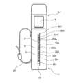
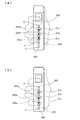
- FIG. 2 is a perspective view illustrating an example of an outer shape of the controller device according to the embodiment of the present invention. It is a schematic rear view showing an example of arrangement of a finger sensor provided in a controller device concerning an embodiment of the invention. It is an explanatory view showing an example of adjustment of arrangement of a finger sensor provided in a controller device concerning an embodiment of the invention. It is an explanatory view showing an example of a fixture provided in a controller device concerning an embodiment of the invention. It is explanatory drawing showing the example of the attachment provided in the controller apparatus which concerns on embodiment of this invention so that attachment or detachment is possible, and the example of the connection part.
- a controller device 1 includes a controller main body 10 and a fixture 20, and communicates with the information processing device 2 by wire or wirelessly. Connected as possible.
- the size, the ratio, the arrangement, and the like of each unit are merely examples, and the example of the present embodiment is not limited to the illustrated size, ratio, and arrangement.
- the fixing device 20 of the controller device 1 is, for example, an annular belt member having both ends fixed to the controller main body 10, and the user places four fingers from the index finger to the little finger between the fixing device 20 and the controller main body 10.
- the belt member of the fixing device 20 is tightened (the annular portion is narrowed) in a state where the controller body 10 is passed, so that the controller main body 10 is fixed to the user's hand. Accordingly, even when the user extends the finger from the state in which the controller body 10 is gripped to the state in which the controller body 10 is not gripped, the controller body 10 does not fall away from the user's hand.
- the controller body 10 includes a gripper 11 that can be gripped by at least some of the fingers (here, the middle finger to the little finger) passed by the user through the fixture 20, and an operation unit 12.
- the grip 11 has a substantially polygonal column shape, and the operation unit 12 is formed continuously from the grip 11.
- the gripping portion 11 When the user grips the gripping portion 11 (the finger is bent to touch the gripping portion 11) on the surface thereof, the gripping portion 11 includes the user's middle finger to the little finger (each finger gripping the gripping portion 11). ) Arrives, and a plurality of finger sensor units 21 are arranged along the longitudinal direction of the grip unit 11 at positions where the finger is separated when the user extends the finger.
- the finger sensor unit 21 is configured by, for example, an electrostatic sensor or an infrared sensor, and each detects the proximity or contact of a finger and outputs a finger detection signal indicating the state of proximity or contact of the finger.
- a plurality of finger sensors 21 are supported by the sensor support 22.
- the sensor support portion 22 includes a linear rail member 221 arranged along the longitudinal direction of the controller main body 10, and a plurality of support members movable along the rail member 221. 222 and the end fixing portion 223, and elastic bodies 224 disposed between the support members 222 adjacent to each other and between the support member 222 and the end fixing portion 223 adjacent to each other.
- the length of the rail member 221 is sufficiently longer than the length from the middle finger to the little finger that grips the grip part 11 of a general user.
- the same number of the support members 222 as the finger sensor units 21 are provided corresponding to the respective finger sensor units 21. .., N that move on the rail member 221, the ends of the rail members 221 are further more than the support members 222 a and 222 n at both ends (upper end and lower end). Arranged on the side.
- the end fixing portion 223 can be switched between a state of moving on the rail member 221 and a state of being fixed on the rail member 221.
- the terminal fixing portion 223 may be fixable to the rail member 221 with a screw or the like. The user loosens the screw fixing the terminal fixing portion 223 to the rail member 221, moves to a desired position on the rail member 221 in this state, and tightens the screw when the terminal fixing portion 223 moves to the desired position. Is fixed to the rail member 221 at the desired position.
- the end fixing portion 223 functions as a restricting unit that restricts the arrangement range of the finger sensor unit 21.
- the elastic bodies 224 are arranged between the finger sensors 21 adjacent to each other, in this case, between the supports 222 supporting the finger sensors 21, and between the support 222 and the distal end fixing portion 223.
- the elastic body 224 biases the support 222 adjacent to each other or the space between the support 222 adjacent to the end and the end fixing portion 223 in a direction away from each other.
- the elastic body 224 functions as a unit that urges the finger sensor units 21 in directions away from each other.
- the elastic coefficient (hook coefficient) of the elastic body 224 is common to each other.
- each elastic body 224 is contracted by receiving the same force. Therefore, the support body 222 (and the finger sensor unit 21 supported on the rail member 221) that moves on the rail member 221 is evenly arranged between the pair of end fixing portions 223 at the ends.
- each finger sensor unit 21 detects proximity or contact of any one of the user's fingers. Therefore, the range in which the support body 222 that supports the finger sensor unit 21 is arranged should be at least a range corresponding to the length L from the middle finger to the little finger of the user.
- the supports 222 are arranged evenly between the pair of end fixing portions 223, when the number of the supports 222 (finger sensor portions 21) is N, The length between the end fixing portions 223 is L ⁇ (N + 1) / (N ⁇ 1) by multiplying (N + 1) by the distance L / (N ⁇ 1) between the support members 222 adjacent to each other.
- the length of the rail member 221 is at least Lmax ⁇ Lmax using the assumed length Lmax from the middle finger to the little finger of the user having the largest hand size and the number N of finger sensors 21 to be arranged. (N + 1) / (N-1). In this example, the length in the longitudinal direction of the grip portion 11 needs to sufficiently exceed the length of the rail member 221.
- the operation unit 12 includes a button operation unit 15 on the front side and a swing button 16 on the back side.
- the operation device 10 includes a control circuit 19 therein.
- the button operation unit 15 is arranged at a position where the thumb of the user reaches when the user grips the grip unit 11 (bends the finger to touch the grip unit 11).
- the swing button 16 is arranged at a position where the index finger of the user reaches when the user grips the gripper 11 (bends the finger to touch the gripper 11).
- the swing button 16 is swingably operated between a first position protruding around the rotation axis and a pushed-in second position with the width direction of the operation unit 12 as a rotation axis.
- the control circuit 19 acquires the content of the pressing operation of the button operation unit 15 and the content of the operation of the swing button 16, and sends information representing the content of the operation to the information processing device 2. Further, the control circuit 19 converts the outputs of the plurality of finger sensor units 21 into digital values and sends the digital values to the information processing device 2 as information representing the result of finger detection.
- the information indicating the detection result of the finger is “0” until the distance between the finger and the finger sensor unit 21 falls below the predetermined distance R, the distance between the finger and the finger sensor unit 21 falls below the distance R, and the distance R becomes The smaller the value, the larger the value, and it is pre-adjusted so that it becomes the maximum value (for example, “255”) when the distance becomes “0” (the state in which the finger is in contact with the finger sensor unit 21).
- the information processing device 2 is a home game machine or the like, and operates according to a program such as a game program.
- the information processing device 2 receives information representing the content of a button operation and information of a finger detection result from the controller main body 10 and executes a game program process and the like using the received information.
- the present embodiment has the above configuration and operates as follows.
- the user Prior to using the controller body 10, the user sets the position of the distal end fixing portion 223 according to the size of his / her hand. Note that, in the following example, when the user grips the grip portion 11, the one on the little finger side of the rail member 221 is referred to as a lower side, and the one on the middle finger side is referred to as an upper side.
- the user having a relatively small hand moves the lower end fixing portion 223 on the rail member 221 from the lower end F of the rail member 221 to the position P. Fixed to. Note that the upper end fixing portion 223 is fixed to the upper end C of the rail member 221.
- the elastic members 224 urge the finger sensor portions 21 adjacent to each other in a direction away from each other.
- each of the elastic members 224 receives the same force.
- the finger sensor 21 is moved from the position C between the pair of terminal fixing portions 223 at the ends, that is, from the position C at the upper end of the rail member 221 to the position P at which the lower terminal fixing portion 223 is locked. It is in a state of being evenly arranged between them (length is l).
- the user with a relatively large hand fixes the lower end fixing portion 223 to the lower end F of the rail member 221 on the rail member 221 as illustrated in FIG. Note that the upper end fixing portion 223 is fixed to the upper end C of the rail member 221.
- the middle finger is placed on the upper end of the rail member 221.
- the distance between the finger sensors 21 is adjusted so that the finger touches the closest finger sensor 21a, and the little finger touches the finger sensor 21c arranged closest to the upper end of the rail member 221.
- one end fixing portion 223 movable on the rail member 221 is disposed on each of the upper side and the lower side.
- the upper end fixing portion 223 is disposed.
- the upper end fixing portion 223 may be fixed to the rail member 221 in advance.
- the upper end fixing portion 223 does not necessarily need to be provided.
- the support 222 supporting the finger sensor portion 21 corresponding to the middle finger (the uppermost finger sensor portion 21a May be fixed at a predetermined position on the rail member 221.
- the finger sensor unit 21 is the uppermost finger sensor unit from the finger sensor unit 21a. It is arranged at intervals L / N between the lengths LL / N up to the portion 21n.
- the lower end fixing portion 223 it is not always necessary to provide the lower end fixing portion 223, and at least one of the supports 222 corresponding to each of the lowermost or uppermost finger sensor portions 21 is railed (for example, by a method such as screwing). What is necessary is just to be able to switch between a state movable on the member 221 and a state fixed to the rail member 221.
- the support body 222 corresponding to each of the lowermost or uppermost finger sensor units 21 is Any of them can be fixed to the rail member 221.
- N finger sensors are L / (N-1).
- the length in which the finger sensor units 21 are arranged is defined, and the finger sensor units 21 are evenly arranged between them.
- the elastic coefficients of the elastic bodies 224 may be different from each other.
- the elastic body 224 between the finger sensor unit 21 corresponding to the middle finger and the finger sensor unit 21 corresponding to the ring finger has better elasticity between the finger sensor unit 21 corresponding to the ring finger and the finger sensor unit 21 corresponding to the little finger. You may make it harder to shrink than the body 224.
- each of the supports 222 corresponding to each finger sensor unit 21 may be switchable between a state in which it can be moved on the rail member 221 and a state in which it is fixed to the rail member 221.
- the user loosens the screw of each support 222 and moves to a desired position. You may make it fix with respect to the rail member 221 with a screw.
- the method of moving or fixing the support member 222 or the end fixing portion 223 that can be switched between the moving state and the fixed state with respect to the rail member 221 is described above with reference to the example using screws.
- the present embodiment is not limited to this example.
- one of the male and female engaging portions is formed on the rail member 221 and the moving state and the fixed state of the support body 222 or the end fixing section 223 are determined.
- the other of the male and female engaging portions is formed on the switchable target, and this engagement is released in a moving state (for example, when the engaging portion is formed of an elastic member, a force is applied.
- the male and female members may be engaged so that the male member and the female member can be fixed on the rail member 221.
- the finger sensor units 21 can be supported in a state where the distance between the finger sensor units 21 adjacent to each other can be changed.
- the arrangement range of the finger sensor unit 21 may be adjusted in conjunction with the fixture 20.
- the fixing device 20 includes a rail member 31, a belt terminal 32 movable on the rail member 31, a belt fixing portion 33, a belt 34, and a buckle 35. Be composed.
- FIG. 4 shows a part of the grip part 11 in a cutaway manner for the sake of explanation.
- the rail member 31 is arranged in a predetermined range on the lower end side of the grip 11 along the longitudinal direction of the grip 11.
- the belt terminal 32 is movable on the rail member 31, and has a columnar support rod 32 ⁇ / b> B that extends in the width direction of the grip portion 11 and around which the belt 34 is wound.
- the support rod 32B is viewed from a plane perpendicular to the longitudinal direction, only the bottom surface of the support rod 32B is shown.
- the belt fixing portion 33 is disposed relatively at the upper end side of the grip portion 11, and one end of the belt 34 is fixed.
- One end of the belt 34 is fixed to a belt fixing portion 33 at a relatively upper end side of the grip portion 11, and the other end of the belt 34 is wound around the support rod 32 ⁇ / b> B of the belt terminal 32 and is disposed on the belt 34.
- the buckle 35 is fixed.
- the user inserts the part from the index finger to the little finger between the belt 34 and the controller main body 10 to the vicinity of the base of the thumb, and tightens the belt 34 in this state.
- the belt terminal 32 around which the belt 34 is wound moves on the rail member 31 toward the upper side of the grip portion 11, and the belt terminal 32 is placed on the little finger of the user's hand (a position corresponding to the fifth metacarpal).
- the movement is restricted when the contact is made.
- the user fixes the length of the belt 34 with the buckle 35 in this state.
- the belt terminal 32 and the lower end fixing portion 223 are connected by a link disposed inside the grip portion 11 so that the movement amount of the belt terminal 32 is transmitted as it is as the movement amount of the end fixing portion 223. You may keep it.
- the distal end fixing portion 223 is placed at the end of the little finger. In this case, the terminal fixing portion 223 does not necessarily need to be fixed to the rail member 221.
- the terminal fixing portion 223 is provided, and the movement of the terminal fixing portion 223 is accompanied by the movement of the belt terminal 32.
- the lower side is used. May be provided along with the movement of the belt terminal 32.
- the support body 222n and the belt terminal 32 may be connected by a link disposed inside the grip portion 11.
- the belt 34 of the fixture 20 for fixing the main body of the controller device 1 to the user's hand is capable of adjusting the circumference of the wheel according to the size of the user's hand.
- the end fixing portion 223 (or the lower end side support 222) moves according to the circumference of the belt 34, and regulates the arrangement range of the finger sensor portion 21. Therefore, in this example, the finger sensors 21 are evenly arranged within the width of the hand, and the finger sensors 21 corresponding to each finger can be arranged simply by wrapping and tightening the fixing tool 20 around the hand without the need for the user to make individual adjustments. Will be placed at the location.
- the elastic member 224 When the support members 222 are connected by the elastic member 224, if the controller device 1 is vigorously shaken or the like, the elastic member 224 may be deformed and the interval between the finger sensors 21 may be changed. Therefore, for example, an acceleration sensor may be provided inside the controller device 1, and information on the acceleration of the controller device 1 detected by the acceleration sensor may be transmitted to the information processing device 2 together with information indicating the detection result of the finger sensor unit 21. Good.
- the information processing device 2 periodically receives, for example, information indicating the detection result of the finger sensor unit 21 and stores the last received information.
- the information processing device 2 receives the information indicating the detection result of the finger sensor unit 21 during that time, Discard without memorizing.
- the information processing device 2 indicates that the acceleration information of the controller device 1 indicates an acceleration exceeding a predetermined threshold value. In this case, the processing may be performed assuming that the user has closed his / her finger (assuming that the user is holding the controller device 1) regardless of the detection result of the finger sensor unit 21.
- an attachment 40 integrated with the housing of the controller device 1 may be attachable to a position of the controller device 1 where the palm of the user's palm (surface of the ball of the ball) abuts.
- the attachment 40 adjusts the distance between the grip 11 and the palm of the user's palm (the surface of the ball of the thumb).
- the attachment 40 may have any shape, but is preferably integrated with the housing of the controller device 1. It is preferable that the controller device 1 includes at least a surface shaped along a curved surface of the housing. By attaching and detaching the attachment 40, the distance from the palm of the user (the surface of the ball of the thumb) to the finger sensor unit 21 is adjusted.
- the attachment attachment portion 41 is provided on the surface of the grip portion 11 of the controller device 1 on the side where the fixture 20 is attached.
- the attachment attachment portion 41 includes, for example, a rail member 411 provided on the surface of the grip 11 as illustrated in FIG. In this case, a slide groove 412 that engages with the rail member 411 and is slidable on the rail member 411 is formed on the attachment 40 side.
- the attachment attachment portion 41 is provided with a protrusion 413 that can be moved by a user operation between, for example, a protruded state and a retracted state, and is attached to the attachment attachment portion 41 on the attachment 40 side.
- a notch 414 that engages with the projection 413 (that is, the movement of the attachment 40 is restricted thereby) may be provided.
- the user engages the slide groove 412 of the attachment 40 with the rail member 411 of the controller device 1, slides the rail member 411 to dispose the attachment 40 at a predetermined position, and sets the protrusion 413 to a projected state.
- the attachment 40 is fixed.
- the outer peripheral length of the grip portion 11 is extended by the width of the attachment 40, so that a user with a relatively large hand can easily operate (for example, a state in which the fingertip reaches just the finger sensor unit 21). Can be.
- a user with a relatively small hand removes the attachment 40 (moves to a state in which the protrusion 413 is retracted, moves the slide groove 412 of the attachment 40 along the rail member 411 to release the engagement state, and removes the attachment.
- the outer peripheral length of the grip portion 11 becomes the original state (the state before the attachment 40 is attached), so that the user can easily operate.
- the attachment 40 is attached and detached here, but the gripper 11 of the controller device 1 may be deformed to change its circumference.
- a balloon body which can be inflated by introducing air into the inside thereof is arranged on the surface of the grip portion 11 on which the fixture 20 is attached, and air is introduced into or exhausted from the balloon body. It may be possible to change the outer peripheral length of the grip portion 11 by using.
- each finger sensor unit 21 may be fixed to a predetermined position of the grip unit 11.
Landscapes
- Engineering & Computer Science (AREA)
- Multimedia (AREA)
- Human Computer Interaction (AREA)
- Theoretical Computer Science (AREA)
- General Engineering & Computer Science (AREA)
- Physics & Mathematics (AREA)
- General Physics & Mathematics (AREA)
- Health & Medical Sciences (AREA)
- Life Sciences & Earth Sciences (AREA)
- Biophysics (AREA)
- Cardiology (AREA)
- General Health & Medical Sciences (AREA)
- Heart & Thoracic Surgery (AREA)
- User Interface Of Digital Computer (AREA)
- Position Input By Displaying (AREA)
Abstract
ユーザの手に装着されるコントローラ装置であって、ユーザの指を検出する複数のセンサ部と、センサ部を支持するセンサ支持部とを備え、センサ支持部は、互いに隣接するセンサ部の間の距離を変更可能な状態で、センサ部を支持する。
Description
本発明は、ユーザの手に装着されるコントローラ装置に関する。
家庭用ゲーム機等におけるコントローラ装置は、ユーザの手の動きを検出して、ゲーム機等の本体に当該検出したユーザの動作を表す情報を送出している。
また近年、こうしたコントローラ装置の一つとして、ユーザの手に装着した状態で、コントローラ装置の表面に配した複数のセンサにより、ユーザの各指の動き(各指の曲げ伸ばし)を検出するものが考えられている。
しかしながら手の大きさは、ユーザごとに区々で、コントローラ装置の表面に配した複数のセンサのどのセンサが、ユーザのどの指の曲げ伸ばしを検出しているのかを知ることが困難となっているのが実情である。
また、コントローラ装置のどの部分まで指の先端が達するかがユーザの手の大きさによって異なる。このため、例えば手の小さいユーザにコントローラ装置を装着し、このユーザが指を曲げている(コントローラ装置の本体に接している)とき、手の比較的大きいユーザに合わせてセンサが配されていると、センサの一部に指が届かず、指が伸びている(コントローラ装置の本体に接していない)と判断されてしまう場合がある。このように、手の大きさの相違によって、コントローラ装置が、十分な精度でユーザの指の動きを検出できない場合がある。
すなわち、ユーザが自らの手の大きさ等に応じて、センサと指との位置関係を調整可能とすることが望まれている。
本発明は上記実情に鑑みて為されたもので、センサとユーザの各指との位置関係を調整可能としたコントローラ装置を提供することを、その目的の一つとする。
上記従来例の問題点を解決する本発明の一態様は、ユーザの手に装着されるコントローラ装置であって、前記ユーザの指を検出する複数のセンサ部と、前記センサ部を支持するセンサ支持部とを備え、前記センサ支持部は、互いに隣接する前記センサ部の間の距離を変更可能な状態で、前記センサ部を支持するものである。
また上記従来例の問題点を解決する本発明のもう一つの態様は、ユーザの手に装着されるコントローラ装置であって、コントローラ装置本体と、手の平から前記コントローラ装置本体までの距離を調整する調整手段が設けられていることとしたものである。
本発明によると、センサとユーザの各指との位置関係が調整可能となる。
本発明の実施の形態について図面を参照しながら説明する。本発明の実施の形態に係るコントローラ装置1は、図1に例示するように、コントローラ本体10と、固定具20とを含んで構成され、有線または無線にて情報処理装置2との間で通信可能に接続される。なお、本実施の形態の以下の説明において、各部の大きさやその比、配置等は一例であり、本実施の形態の例は、図示等した大きさや比率、配置に限られるものではない。
コントローラ装置1の固定具20は、例えばコントローラ本体10に両端が固定された環状のベルト部材であり、ユーザはこの固定具20とコントローラ本体10との間に人差し指から小指までの4本の指を通した状態で固定具20のベルト部材を締めて(環状部を狭くして)ユーザの手にコントローラ本体10を固定した状態とする。これにより、ユーザがコントローラ本体10を把持した状態から、指を伸ばしてコントローラ本体10を把持しない状態となっても、コントローラ本体10がユーザの手から離れて落ちてしまうことがない。
コントローラ本体10は、ユーザが固定具20に通した、少なくとも一部の指(ここでは中指から小指とする)で把持可能な把持部11と、操作部12とを含む。把持部11は、実質的に多角形柱状をなし、操作部12が、この把持部11から連続して形成される。
把持部11は、その表面のうち、把持部11をユーザが把持した(指を曲げて把持部11に触れる状態とした)ときに、ユーザの中指から小指まで(把持部11を把持する各指)が到達し、ユーザが指を伸ばしたときには指が離れる位置に、把持部11の長手方向に沿って複数の指センサ部21が配される。
この指センサ部21は、例えば静電センサや赤外線センサにより構成され、それぞれが指の近接、または接触を検出して、指の近接または接触の状態を表す指検出信号を出力する。本実施の形態の一例では、複数の指センサ部21がセンサ支持部22によって支持される。ここでセンサ支持部22は、図2に例示するように、コントローラ本体10の長手方向に沿って配された直線状のレール部材221と、このレール部材221に沿って移動可能な複数の支持体222及び末端固定部223と、互いに隣接する支持体222間、及び互いに隣接する支持体222と末端固定部223との間にそれぞれ配される弾性体224とを含んで構成される。
本実施の形態のこの例では、レール部材221は、後に述べるように、一般的なユーザの把持部11を把持する中指から小指までの長さよりも十分長くしておく。
支持体222は指センサ部21のそれぞれに対応して、指センサ部21と同数だけ設けられる。また末端固定部223は、レール部材221上で移動する支持体222a,b,…,nのうち、両末端(上側端及び下側端)の支持体222a,222nよりそれぞれさらにレール部材221の末端側に配される。
またこの末端固定部223は、レール部材221上を移動する状態と、レール部材221上で固定された状態とが切り替え可能となっている。具体的にこの末端固定部223はレール部材221に対してネジ等で固定可能となっていてもよい。ユーザは、末端固定部223をレール部材221に固定するネジを緩め、この状態でレール部材221上の所望の位置まで移動し、所望の位置まで移動したら上記ネジを締結して、末端固定部223を、当該所望の位置でレール部材221に固定された状態とする。本実施の形態のここでの例では、この末端固定部223が、指センサ部21の配列範囲を規制する規制手段として機能する。
弾性体224は、互いに隣接する指センサ部21間、ここでは指センサ部21を支持する支持体222間と、支持体222と末端固定部223との間にそれぞれ配される。この弾性体224は、互いに隣接する支持体222間、または互いに隣接する支持体222と末端固定部223との間隔が互いに離れる方向に付勢している。これにより、この弾性体224が、指センサ部21を互いに離れる方向に付勢する手段として機能する。
なお、本実施の形態の一例では、この弾性体224の弾性係数(フック係数)は、互いに共通としておく。このようにすると、末端の一対の末端固定部223をそれぞれレール部材221上に固定したとき、各弾性体224がいずれも同じ力を受けて縮められる。そのためレール部材221上を移動する支持体222(及びそれに支持される指センサ部21)が、これら末端の一対の末端固定部223の間に均等に配されることとなる。
本実施の形態では、各指センサ部21がそれぞれ、ユーザのいずれかの指の近接または接触を検出することが好適である。そのため、指センサ部21を支持する支持体222の配置される範囲は、少なくともユーザの中指から小指までの長さLに相当する範囲とするようにしておく。本実施の形態のここでの例では、一対の末端固定部223間に均等に支持体222が配されることとしているので、支持体222(指センサ部21)の数をNとしたとき、末端固定部223間の長さは、互いに隣接する支持体222の距離L/(N-1)に、(N+1)を乗じて、L×(N+1)/(N-1)となる。従って、レール部材221の長さは、想定される、最大の手の大きさのユーザの中指から小指までの長さLmaxと、配置する指センサ部21の数Nとを用いて、少なくともLmax×(N+1)/(N-1)と定める。この例では、把持部11の長手方向の長さは、このレール部材221の長さを十分超える必要がある。
操作部12には、正面側にボタン操作部15を含み、背面側に、揺動ボタン16を備えて構成される。またこの操作デバイス10は、内部に制御回路19を含んで構成されている。
ボタン操作部15は、把持部11をユーザが把持した(指を曲げて把持部11に触れる状態とした)ときに、ユーザの親指の到達する位置に配される。
揺動ボタン16は、把持部11をユーザが把持した(指を曲げて把持部11に触れる状態とした)ときに、ユーザの人差し指が到達する位置に配される。この揺動ボタン16は、操作部12の幅方向を回転軸として、この回転軸を中心として突出した第一の位置と、押し込まれた第二の位置との間で揺動操作される。
制御回路19は、ボタン操作部15の押下操作や揺動ボタン16の操作の内容を取得して、当該操作の内容を表す情報を、情報処理装置2に対して送出する。またこの制御回路19は、複数の指センサ部21のそれぞれの出力をディジタル値に変換して、指の検出結果を表す情報として情報処理装置2に対して送出する。この指の検出結果を表す情報は、指と指センサ部21との距離が所定の距離Rを下回るまでは「0」、指と指センサ部21との距離が距離Rを下回り、距離Rが小さくなるほど大きくなり、距離が「0」(指が指センサ部21に接触した状態)となったときに最大値(例えば「255」)となるように予め調整しておくものとする。
情報処理装置2は、家庭用ゲーム機等であり、ゲームプログラム等のプログラムに従って動作する。この情報処理装置2は、コントローラ本体10から、ボタン操作の内容を表す情報や、指の検出結果の情報を受け入れて、当該受け入れた情報を用いてゲームプログラムの処理等を実行する。
本実施の形態は以上の構成を備え、次のように動作する。ユーザは、コントローラ本体10を利用するに先立って、自己の手の大きさに合わせて末端固定部223の位置を設定する。なお、以下の例では、ユーザが把持部11を把持したとき、レール部材221の小指側となるほうを下側、中指側となるほうを上側と呼ぶ。
具体的に、手が比較的小さいユーザは、図3(a)に例示するように、レール部材221上で、下側の末端固定部223をレール部材221の下端Fから上側に移動した位置Pに固定する。なお、上側の末端固定部223は、レール部材221の上側端Cに固定しておくものとする。またここでの例では、指センサ部21の数Nは、検出する指の数(つまりここでは中指,薬指,小指の検出を行うので、N=3)としておく。
このとき弾性体224が、互いに隣接する指センサ部21を互いに離れる方向に付勢しており、末端固定部223を上記の位置Pに固定したとき、各弾性体224がいずれも同じ力を受けて縮められて、指センサ部21が、上記末端の一対の末端固定部223の間、つまりレール部材221の上側端の位置Cから、下側の末端固定部223を係止した位置Pまでの間(長さをlとする)に均等に配された状態となる。
これにより、手が比較的小さいユーザが、人差し指が揺動ボタン16を操作可能な状態で把持部11を(中指から小指で)把持したとき、中指は(人差し指と中指との間隔はあまり変化しない)レール部材221の上側端に最も近い指センサ部21aに触れる状態となり、小指はレール部材221の上側端に最も近い位置に配された指センサ部21cに触れるように、下側の末端固定部223の位置Pを定めることができる。
一方、手が比較的大きいユーザは、図3(b)に例示するように、レール部材221上で、下側の末端固定部223をレール部材221の下端Fに固定する。なお、上側の末端固定部223は、レール部材221の上側端Cに固定しておくものとする。
これにより、手が比較的大きいユーザに対しては、その人差し指が揺動ボタン16を操作可能な状態で把持部11を(中指から小指で)把持したとき、中指はレール部材221の上側端に最も近い指センサ部21aに触れる状態となり、小指はレール部材221の上側端に最も近い位置に配された指センサ部21cに触れるように、指センサ部21の間隔が調整される。
なお、ここまでの例では、レール部材221上を移動可能な末端固定部223は上側と下側とにそれぞれ一つずつ配されるものとしたが、上記の例のように上側の末端固定部223をレール部材221の上端側に固定する場合、上側の末端固定部223はレール部材221に予め固定しておいてもよい。また、このようにするのであれば、上側の末端固定部223は必ずしも設ける必要はなく、上側端では、中指に対応する指センサ部21を支持する支持体222(最も上側となる指センサ部21aを支持する支持体222a)を、レール部材221上の所定の位置に固定しておくこととしてもよい。
この場合、当該最も上側に位置する指センサ部21aから下側の末端固定部223までの長さをLとしたとき、指センサ部21は、上記指センサ部21aから最も上側に位置する指センサ部21nまでの長さL-L/Nの間に、間隔L/Nだけ間隔を置いて配されることとなる。
さらに、下側の末端固定部223を必ずしも設ける必要はなく、最も下側あるいは最も上側の指センサ部21のそれぞれに対応する支持体222の少なくとも一方を、(例えばネジ止め等の方法により)レール部材221上で移動可能な状態と、レール部材221に対して固定した状態とに切り替え可能としておけばよい、また、最も下側あるいは最も上側の指センサ部21のそれぞれに対応する支持体222はいずれもレール部材221に対して固定可能としておく。
この例では、最も上側に位置する指センサ部21aから最も下側に位置する指センサ部21nまでの長さをLとしたとき、N個の指センサが、この長さLの間に、L/(N-1)だけ間隔を置いて配されることとなる。
さらにここまでの説明では、指センサ部21を配置する長さを規定して、その間に均等に指センサ部21が配されるようにしていたが本実施の形態はこれに限られない。例えば弾性体224の弾性係数を互いに異ならせてもよい。例えば中指に対応する指センサ部21と薬指に対応する指センサ部21との間の弾性体224のほうが、薬指に対応する指センサ部21と小指に対応する指センサ部21との間の弾性体224よりも、縮められにくいものとしておいてもよい。
また各指センサ部21に対応する支持体222のそれぞれが、レール部材221上で移動可能な状態と、レール部材221に対して固定した状態とに切り替え可能となっていてもよい。例えば各支持体222をレール部材221にネジ等により係止するようにしておく場合、ユーザは、各支持体222のネジを緩めて所望の位置に移動し、所望の位置に移動したらその位置でネジによりレール部材221に対して固定するようにしてもよい。
さらに支持体222あるいは末端固定部223のうち、移動する状態と固定される状態とを切り替え可能なものをレール部材221に対して移動ないし固定する方法も、ここまでの説明ではネジによる例について説明したが、本実施の形態はこの例に限られず、例えばレール部材221にオスメス係合部の一方を形成し、支持体222あるいは末端固定部223のうち、移動する状態と固定される状態とを切り替え可能な対象物に、オスメス係合部の他方を形成して、移動する状態ではこの係合を解除(例えば上記係合部を、弾性を有する部材で形成することで、力を加えると係合を解除できるようにしておく)し、固定する状態では、当該オスメスの係合によりレール部材221上に固定できるようにしておいてもよい。
このような例によっても、互いに隣接する指センサ部21の間の距離を変更可能な状態で、指センサ部21を支持することが可能となる。
[固定具に連動させる例]
また、本実施の形態の一例において、指センサ部21の配置範囲は、固定具20に連動して調整されてもよい。この例では固定具20は、図4に示すように、レール部材31と、このレール部材31上を移動可能なベルト端子32と、ベルト固定部33と、ベルト34と、バックル35とを含んで構成される。図4は、説明のため、把持部11の一部を破断して示している。
また、本実施の形態の一例において、指センサ部21の配置範囲は、固定具20に連動して調整されてもよい。この例では固定具20は、図4に示すように、レール部材31と、このレール部材31上を移動可能なベルト端子32と、ベルト固定部33と、ベルト34と、バックル35とを含んで構成される。図4は、説明のため、把持部11の一部を破断して示している。
このレール部材31は、把持部11の下端側の所定範囲に、把持部11の長手方向に沿って配される。ベルト端子32は、レール部材31上を移動可能となっており、把持部11の幅方向に延びてベルト34を巻き掛けた、柱状の支持棒32Bを有する。図4では支持棒32Bを、その長手方向に垂直な面から見ているため、支持棒32Bは底面のみが示されている。
ベルト固定部33は、把持部11の比較的上端側に配され、ベルト34の一端が固定される。ベルト34は、その一端が把持部11の比較的上端側にあるベルト固定部33に固定され、またベルト34の他端側は、ベルト端子32の支持棒32Bに巻きかかり、ベルト34上に配されたバックル35にて固定される。
ユーザは、ベルト34とコントローラ本体10との間に人差し指から小指までの部分を親指の付け根付近まで挿入し、その状態で、ベルト34を締める。このとき、ベルト34が巻きかかっているベルト端子32がレール部材31上を、把持部11の上側に向かって移動し、ユーザの手の小指球(第五中手骨に相当する位置)にベルト34が当接したところでその移動が規制される。ユーザはこの状態でバックル35によりベルト34の長さを固定する。
本実施の形態のこの例において特徴的なことは、ここでベルト端子32の移動に伴い、下側末端固定部223が、レール部材221上で移動するよう、ベルト端子32と下側末端固定部223とを連動させていることである。
一例としてベルト端子32と下側の末端固定部223とを把持部11内部に配したリンクによって結合しておき、ベルト端子32の移動量がそのまま末端固定部223の移動量として伝達されるようにしておいてもよい。これによると、末端固定部223が小指端部に配された状態となる。この場合、末端固定部223は、必ずしもレール部材221に固定される必要がない。
また、ここでは末端固定部223を設け、末端固定部223の移動が、ベルト端子32の移動に伴う例としたが、本実施の形態において下側に末端固定部223を設けない場合、下側の端に配された支持体222nが、ベルト端子32の移動に伴うものとしてもよい。この場合は、当該支持体222nと、ベルト端子32とを把持部11内部に配したリンクによって結合すればよい。
この例によると、コントローラ装置1の本体をユーザの手に固定する固定具20のベルト34が、ユーザの手の大きさに合わせて輪の周長を調整可能となっており、規制手段としての末端固定部223(または下端側の支持体222)が、このベルト34の輪の周長に応じて移動し、指センサ部21の配列範囲を規制することとなる。従って、この例では、ユーザが一々調整をするまでもなく、固定具20を手に巻き付けて締めるだけで、指センサ部21が手の幅の範囲内で均等に配列され、各指に対応する位置に配されることとなる。
なお、支持体222間を弾性体224で連結する場合、コントローラ装置1を激しく振る等の操作があると、弾性体224が変形して、指センサ部21の間の間隔が変動する場合がある。そこで例えばコントローラ装置1内部に加速度センサを配しておき、この加速度センサにより検出したコントローラ装置1の加速度の情報を、指センサ部21の検出結果を表す情報とともに情報処理装置2に送信してもよい。
情報処理装置2は、例えば指センサ部21の検出結果を表す情報を定期的に受信し、最後に受信した情報を記憶しておくものとする。そして情報処理装置2は、コントローラ装置1の加速度の情報が、予め定めたしきい値を超える加速度を表すものとなっているときには、その間に受信した指センサ部21の検出結果を表す情報は、記憶せずに破棄する。
これにより、大きい加速度で移動する直前の情報がそのまま利用されることとなる。なお、加速度が大きい場合はユーザがコントローラ装置1を把持していることが多いと考えられるので、情報処理装置2は、コントローラ装置1の加速度の情報が所定のしきい値を超える加速度を表すものとなっている場合、指センサ部21の検出の結果によらず、ユーザが指を閉じているものとして(コントローラ装置1を把持しているものとして)、処理を行ってもよい。
[手の平から指センサ部までの距離を調整可能とする例]
また本実施の形態において、コントローラ装置1のユーザの手の平(母指球表面)が当接する位置には、コントローラ装置1の筐体と一体となるアタッチメント40が取り付け可能となっていてもよい。
また本実施の形態において、コントローラ装置1のユーザの手の平(母指球表面)が当接する位置には、コントローラ装置1の筐体と一体となるアタッチメント40が取り付け可能となっていてもよい。
このアタッチメント40は、把持部11とユーザの手の平(母指球表面)との間隔を調整するものであり、その形状は問わないが、コントローラ装置1の筐体と一体的となることが好ましいので、コントローラ装置1の筐体の曲面に沿った形状の面を少なくとも備えることが好適である。このアタッチメント40を着脱することでユーザの手の平(母指球表面)から指センサ部21までの距離が調整される。
すなわちこの例では、コントローラ装置1の把持部11の固定具20を取り付けた側の面に、アタッチメント取り付け部41が設けられる。このアタッチメント取り付け部41は、例えば、図5に例示するように、把持部11表面に設けられたレール部材411を含む。またこの場合、アタッチメント40側には、このレール部材411に係合し、レール部材411上をスライド可能なスライド溝412が形成される。
またこのアタッチメント取り付け部41には、例えば突出した状態と、引き込んだ状態との間で、ユーザの操作により移動可能な突起413が設けられ、アタッチメント40側には、アタッチメント取り付け部41に取り付けられた状態で、当該突起413に係合する(つまりアタッチメント40の移動がそれにより規制される)切り欠き414が設けられてもよい。
ユーザは、アタッチメント40のスライド溝412をコントローラ装置1のレール部材411に係合させ、レール部材411上をスライドさせて所定の位置にアタッチメント40を配した上で、突起413を突出した状態にすることで、アタッチメント40を固定する。
これによりアタッチメント40の幅だけ把持部11の外周長が延長され、手の比較的大きいユーザにとって、操作しやすい状態(例えばその指先がちょうど指センサ部21に到達する程度となる状態)とすることができる。
また手の比較的小さいユーザは、このアタッチメント40を取り外す(突起413を引き込んだ状態に移動し、アタッチメント40のスライド溝412をレール部材411に沿って移動して、係合状態を解除し、アタッチメント40を取り外す)ことで、把持部11の外周長がもとの状態(アタッチメント40を取り付ける前の状態)となり、当該ユーザにとって操作しやすい状態とすることができる。
なお、ここではアタッチメント40を着脱することとしたが、コントローラ装置1の把持部11を変形してその周長を変動することとしてもよい。例えば把持部11の固定具20を取り付けた側の面に、内部に空気を導入することによって膨らませることのできる風船体を配しておき、この風船体に空気を導入し、あるいは排気することで把持部11の外周長を変更できるようにしてもよい。
なお、本実施の形態の、この手の平から指センサ部までの距離を調整可能とする例では、各指センサ部間の間隔の調整は必ずしも必要ではない。つまり、各指センサ部21は、把持部11の所定の位置に固定されていてもよい。
1 コントローラ装置、2 情報処理装置、10 コントローラ本体、11 把持部、12 操作部、15 ボタン操作部、16 揺動ボタン、19 制御回路、20 固定具、21 指センサ部、22 センサ支持部、31 レール部材、32B 支持棒、32 ベルト端子、33 ベルト固定部、34 ベルト、35 バックル、40 アタッチメント、41 アタッチメント取り付け部、221 レール部材、222 支持体、223 末端固定部、224 弾性体、411 レール部材、412 スライド溝、413 突起、414 切り欠き。
Claims (7)
- ユーザの手に装着されるコントローラ装置であって、
前記ユーザの指を検出する複数のセンサ部と、
前記センサ部を支持するセンサ支持部とを備え、
前記センサ支持部は、互いに隣接する前記センサ部の間の距離を変更可能な状態で、前記センサ部を支持するコントローラ装置。 - 請求項1記載のコントローラ装置であって、
前記センサ支持部は、前記センサ部の間に配され、前記センサ部を互いに離れる方向に付勢する弾性体と、
前記センサ部の配列範囲を規制する規制手段とを備えてなるコントローラ装置。 - 請求項2記載のコントローラ装置であって、
デバイス本体をユーザの手に固定するベルトであって、ユーザの手の大きさに合わせて周長を調整可能なベルトをさらに有し、
前記規制手段は、前記ベルトの周長に応じて前記センサ部の配列範囲を規制するコントローラ装置。 - ユーザの手に装着されるコントローラ装置であって、
コントローラ装置本体と、
手の平から前記コントローラ装置本体までの距離を調整する調整手段が設けられているコントローラ装置。 - 請求項4に記載のコントローラ装置であって、
前記調整手段は前記コントローラ装置本体側に配されたアタッチメント取り付け部と、
前記アタッチメント取り付け部に対して着脱可能なアタッチメントとを含むコントローラ装置。 - ユーザの手に装着されるコントローラ装置であって、
コントローラ装置本体と、
前記ユーザの指を検出する複数のセンサ部と、
前記センサ部を支持するセンサ支持部と、
手の平から前記コントローラ装置本体までの距離を調整する調整手段と、を備え、
前記センサ支持部は、互いに隣接する前記センサ部の間の距離を変更可能な状態で、前記センサ部を支持するコントローラ装置。 - ユーザの手に装着されるコントローラ装置に取り付けられるアタッチメントであって、
前記コントローラ装置のコントローラ装置本体側に配されたアタッチメント取り付け部に着脱可能に取り付けられ、ユーザの手の平から前記コントローラ装置本体までの距離を調整するアタッチメント。
Priority Applications (3)
| Application Number | Priority Date | Filing Date | Title |
|---|---|---|---|
| PCT/JP2018/029675 WO2020031271A1 (ja) | 2018-08-07 | 2018-08-07 | コントローラ装置 |
| JP2020535378A JP6956273B2 (ja) | 2018-08-07 | 2018-08-07 | コントローラ装置 |
| US17/263,761 US11648464B2 (en) | 2018-08-07 | 2018-08-07 | Controller device |
Applications Claiming Priority (1)
| Application Number | Priority Date | Filing Date | Title |
|---|---|---|---|
| PCT/JP2018/029675 WO2020031271A1 (ja) | 2018-08-07 | 2018-08-07 | コントローラ装置 |
Publications (1)
| Publication Number | Publication Date |
|---|---|
| WO2020031271A1 true WO2020031271A1 (ja) | 2020-02-13 |
Family
ID=69415258
Family Applications (1)
| Application Number | Title | Priority Date | Filing Date |
|---|---|---|---|
| PCT/JP2018/029675 Ceased WO2020031271A1 (ja) | 2018-08-07 | 2018-08-07 | コントローラ装置 |
Country Status (3)
| Country | Link |
|---|---|
| US (1) | US11648464B2 (ja) |
| JP (1) | JP6956273B2 (ja) |
| WO (1) | WO2020031271A1 (ja) |
Cited By (2)
| Publication number | Priority date | Publication date | Assignee | Title |
|---|---|---|---|---|
| WO2023127426A1 (ja) * | 2021-12-27 | 2023-07-06 | 株式会社村田製作所 | ハプティクス装置 |
| JP2024521020A (ja) * | 2021-05-18 | 2024-05-28 | バルブ コーポレーション | 直線状ハンドストラップアジャスタを備えた電子コントローラ |
Citations (3)
| Publication number | Priority date | Publication date | Assignee | Title |
|---|---|---|---|---|
| JP3132531U (ja) * | 2007-03-22 | 2007-06-14 | 株式会社バンダイナムコゲームス | 装着具 |
| WO2017149888A1 (ja) * | 2016-03-04 | 2017-09-08 | 株式会社ソニー・インタラクティブエンタテインメント | 操作装置 |
| JP2018000735A (ja) * | 2016-07-06 | 2018-01-11 | 株式会社ソニー・インタラクティブエンタテインメント | 拡縮装置及び操作装置 |
Family Cites Families (3)
| Publication number | Priority date | Publication date | Assignee | Title |
|---|---|---|---|---|
| JPH0822349A (ja) | 1994-07-06 | 1996-01-23 | Ricoh Co Ltd | 操作パネル |
| US10391400B1 (en) * | 2016-10-11 | 2019-08-27 | Valve Corporation | Electronic controller with hand retainer and finger motion sensing |
| WO2018079383A1 (ja) | 2016-10-28 | 2018-05-03 | 株式会社ソニー・インタラクティブエンタテインメント | 情報処理装置、制御方法、プログラム、及び記録媒体 |
-
2018
- 2018-08-07 US US17/263,761 patent/US11648464B2/en active Active
- 2018-08-07 WO PCT/JP2018/029675 patent/WO2020031271A1/ja not_active Ceased
- 2018-08-07 JP JP2020535378A patent/JP6956273B2/ja active Active
Patent Citations (3)
| Publication number | Priority date | Publication date | Assignee | Title |
|---|---|---|---|---|
| JP3132531U (ja) * | 2007-03-22 | 2007-06-14 | 株式会社バンダイナムコゲームス | 装着具 |
| WO2017149888A1 (ja) * | 2016-03-04 | 2017-09-08 | 株式会社ソニー・インタラクティブエンタテインメント | 操作装置 |
| JP2018000735A (ja) * | 2016-07-06 | 2018-01-11 | 株式会社ソニー・インタラクティブエンタテインメント | 拡縮装置及び操作装置 |
Cited By (5)
| Publication number | Priority date | Publication date | Assignee | Title |
|---|---|---|---|---|
| JP2024521020A (ja) * | 2021-05-18 | 2024-05-28 | バルブ コーポレーション | 直線状ハンドストラップアジャスタを備えた電子コントローラ |
| EP4313335A4 (en) * | 2021-05-18 | 2024-12-11 | Valve Corporation | ELECTRONIC CONTROL DEVICE WITH LINEAR STRAP ADJUSTMENT DEVICE |
| WO2023127426A1 (ja) * | 2021-12-27 | 2023-07-06 | 株式会社村田製作所 | ハプティクス装置 |
| JPWO2023127426A1 (ja) * | 2021-12-27 | 2023-07-06 | ||
| JP7722471B2 (ja) | 2021-12-27 | 2025-08-13 | 株式会社村田製作所 | ハプティクス装置 |
Also Published As
| Publication number | Publication date |
|---|---|
| US11648464B2 (en) | 2023-05-16 |
| JPWO2020031271A1 (ja) | 2021-04-30 |
| JP6956273B2 (ja) | 2021-11-02 |
| US20210299555A1 (en) | 2021-09-30 |
Similar Documents
| Publication | Publication Date | Title |
|---|---|---|
| US10723016B2 (en) | Wearable hand robot | |
| US11504615B1 (en) | Electronic controller with linear hand strap adjuster | |
| JP7000593B2 (ja) | 情報処理システム、コントローラ装置、情報処理装置、及びプログラム | |
| US10232254B2 (en) | Game controller with removable paddle accessory | |
| US20190278372A1 (en) | Information processing system, controller device, controller device control method and program | |
| KR100760083B1 (ko) | 악력기 | |
| KR101515951B1 (ko) | 손가락 운동 장치 | |
| JP6535496B2 (ja) | 医療用処置具把持具 | |
| JP6956273B2 (ja) | コントローラ装置 | |
| KR20190059529A (ko) | 착용형 손 로봇 | |
| JPWO2020079854A1 (ja) | コントローラ装置、その制御方法、及びプログラム | |
| JP6479376B2 (ja) | 可動義手 | |
| CN113747955B (zh) | 具有手指感应和可调节的手固定器的电子控制器 | |
| KR101473113B1 (ko) | 터치 펜 | |
| JP3176931U (ja) | 打球用具のグリップ矯正具 | |
| Wang et al. | Design and performance of a haptic data acquisition glove | |
| JP2011221475A (ja) | 撮影用具 | |
| JP5695262B1 (ja) | バイオリンのネック部における左手保型用補助具 | |
| JP5130573B2 (ja) | ロボットハンド装置 | |
| US20240231493A9 (en) | Force sense presentation device | |
| JP2019076786A (ja) | 可動義手 | |
| US20150363010A1 (en) | Finger-driven computer mouse | |
| US20120103173A1 (en) | Human-Machine Interface | |
| JP3506636B2 (ja) | 箸の使用法訓練具 | |
| KR20180086058A (ko) | 핑거 탭 |
Legal Events
| Date | Code | Title | Description |
|---|---|---|---|
| 121 | Ep: the epo has been informed by wipo that ep was designated in this application |
Ref document number: 18929040 Country of ref document: EP Kind code of ref document: A1 |
|
| ENP | Entry into the national phase |
Ref document number: 2020535378 Country of ref document: JP Kind code of ref document: A |
|
| NENP | Non-entry into the national phase |
Ref country code: DE |
|
| 122 | Ep: pct application non-entry in european phase |
Ref document number: 18929040 Country of ref document: EP Kind code of ref document: A1 |