WO2020027215A1 - Grain-oriented electromagnetic steel sheet - Google Patents
Grain-oriented electromagnetic steel sheet Download PDFInfo
- Publication number
- WO2020027215A1 WO2020027215A1 PCT/JP2019/030059 JP2019030059W WO2020027215A1 WO 2020027215 A1 WO2020027215 A1 WO 2020027215A1 JP 2019030059 W JP2019030059 W JP 2019030059W WO 2020027215 A1 WO2020027215 A1 WO 2020027215A1
- Authority
- WO
- WIPO (PCT)
- Prior art keywords
- grain
- steel sheet
- oriented electrical
- electrical steel
- rolling direction
- Prior art date
Links
- 229910000831 Steel Inorganic materials 0.000 title claims abstract description 177
- 239000010959 steel Substances 0.000 title claims abstract description 177
- 239000013078 crystal Substances 0.000 claims abstract description 337
- 239000002245 particle Substances 0.000 claims description 283
- 238000005096 rolling process Methods 0.000 claims description 275
- 229910001224 Grain-oriented electrical steel Inorganic materials 0.000 claims description 269
- 229910052742 iron Inorganic materials 0.000 claims description 146
- 238000000034 method Methods 0.000 claims description 114
- 238000005259 measurement Methods 0.000 claims description 92
- 239000000203 mixture Substances 0.000 claims description 76
- 239000000126 substance Substances 0.000 claims description 76
- 239000011248 coating agent Substances 0.000 claims description 52
- 238000000576 coating method Methods 0.000 claims description 52
- 229910052758 niobium Inorganic materials 0.000 claims description 25
- 229910052720 vanadium Inorganic materials 0.000 claims description 24
- 230000005381 magnetic domain Effects 0.000 claims description 23
- 229910052715 tantalum Inorganic materials 0.000 claims description 23
- 229910052750 molybdenum Inorganic materials 0.000 claims description 22
- 229910052721 tungsten Inorganic materials 0.000 claims description 22
- 230000015572 biosynthetic process Effects 0.000 claims description 15
- 229910052839 forsterite Inorganic materials 0.000 claims description 15
- HCWCAKKEBCNQJP-UHFFFAOYSA-N magnesium orthosilicate Chemical group [Mg+2].[Mg+2].[O-][Si]([O-])([O-])[O-] HCWCAKKEBCNQJP-UHFFFAOYSA-N 0.000 claims description 15
- 239000012535 impurity Substances 0.000 claims description 12
- XEEYBQQBJWHFJM-UHFFFAOYSA-N Iron Chemical compound [Fe] XEEYBQQBJWHFJM-UHFFFAOYSA-N 0.000 description 294
- 238000000137 annealing Methods 0.000 description 189
- 239000010955 niobium Substances 0.000 description 164
- 238000001953 recrystallisation Methods 0.000 description 162
- 238000004519 manufacturing process Methods 0.000 description 99
- 238000010438 heat treatment Methods 0.000 description 92
- 239000003112 inhibitor Substances 0.000 description 65
- 230000001276 controlling effect Effects 0.000 description 60
- 239000010410 layer Substances 0.000 description 57
- 230000000694 effects Effects 0.000 description 53
- 230000008569 process Effects 0.000 description 53
- 230000001965 increasing effect Effects 0.000 description 49
- 230000002349 favourable effect Effects 0.000 description 39
- 229910000976 Electrical steel Inorganic materials 0.000 description 36
- 230000000052 comparative effect Effects 0.000 description 36
- 230000008859 change Effects 0.000 description 33
- 238000005121 nitriding Methods 0.000 description 30
- 239000002244 precipitate Substances 0.000 description 28
- 230000002829 reductive effect Effects 0.000 description 27
- 238000011156 evaluation Methods 0.000 description 26
- 239000011669 selenium Substances 0.000 description 23
- 230000004907 flux Effects 0.000 description 21
- 229910052717 sulfur Inorganic materials 0.000 description 21
- 229910052711 selenium Inorganic materials 0.000 description 19
- 238000005520 cutting process Methods 0.000 description 17
- 238000005098 hot rolling Methods 0.000 description 17
- 150000004767 nitrides Chemical class 0.000 description 16
- 229910019142 PO4 Inorganic materials 0.000 description 14
- VYPSYNLAJGMNEJ-UHFFFAOYSA-N Silicium dioxide Chemical compound O=[Si]=O VYPSYNLAJGMNEJ-UHFFFAOYSA-N 0.000 description 14
- 239000008119 colloidal silica Substances 0.000 description 14
- 230000006870 function Effects 0.000 description 14
- 239000011572 manganese Substances 0.000 description 14
- 239000010452 phosphate Substances 0.000 description 14
- NBIIXXVUZAFLBC-UHFFFAOYSA-K phosphate Chemical compound [O-]P([O-])([O-])=O NBIIXXVUZAFLBC-UHFFFAOYSA-K 0.000 description 14
- 239000002436 steel type Substances 0.000 description 14
- 238000005097 cold rolling Methods 0.000 description 13
- 239000012467 final product Substances 0.000 description 12
- 230000005415 magnetization Effects 0.000 description 11
- VEXZGXHMUGYJMC-UHFFFAOYSA-N Hydrochloric acid Chemical compound Cl VEXZGXHMUGYJMC-UHFFFAOYSA-N 0.000 description 10
- 238000009826 distribution Methods 0.000 description 10
- 238000009413 insulation Methods 0.000 description 10
- 229910052757 nitrogen Inorganic materials 0.000 description 10
- HEMHJVSKTPXQMS-UHFFFAOYSA-M Sodium hydroxide Chemical compound [OH-].[Na+] HEMHJVSKTPXQMS-UHFFFAOYSA-M 0.000 description 9
- 229910052782 aluminium Inorganic materials 0.000 description 9
- 238000000746 purification Methods 0.000 description 9
- IJGRMHOSHXDMSA-UHFFFAOYSA-N Atomic nitrogen Chemical compound N#N IJGRMHOSHXDMSA-UHFFFAOYSA-N 0.000 description 8
- 229910052799 carbon Inorganic materials 0.000 description 8
- 239000011651 chromium Substances 0.000 description 8
- 230000007423 decrease Effects 0.000 description 8
- 230000007547 defect Effects 0.000 description 8
- PXHVJJICTQNCMI-UHFFFAOYSA-N nickel Substances [Ni] PXHVJJICTQNCMI-UHFFFAOYSA-N 0.000 description 8
- 239000002994 raw material Substances 0.000 description 8
- 239000002344 surface layer Substances 0.000 description 8
- PNEYBMLMFCGWSK-UHFFFAOYSA-N aluminium oxide Inorganic materials [O-2].[O-2].[O-2].[Al+3].[Al+3] PNEYBMLMFCGWSK-UHFFFAOYSA-N 0.000 description 7
- 239000010949 copper Substances 0.000 description 7
- 230000000875 corresponding effect Effects 0.000 description 7
- 238000005261 decarburization Methods 0.000 description 7
- 238000013459 approach Methods 0.000 description 6
- 238000005266 casting Methods 0.000 description 6
- 239000003795 chemical substances by application Substances 0.000 description 6
- 229910052804 chromium Inorganic materials 0.000 description 6
- 230000006872 improvement Effects 0.000 description 6
- 229910052748 manganese Inorganic materials 0.000 description 6
- 230000007246 mechanism Effects 0.000 description 6
- 238000012360 testing method Methods 0.000 description 6
- 239000010936 titanium Substances 0.000 description 6
- 229910052787 antimony Inorganic materials 0.000 description 5
- 229910052797 bismuth Inorganic materials 0.000 description 5
- 229910052796 boron Inorganic materials 0.000 description 5
- 239000010960 cold rolled steel Substances 0.000 description 5
- 229910052802 copper Inorganic materials 0.000 description 5
- 238000000354 decomposition reaction Methods 0.000 description 5
- 238000005530 etching Methods 0.000 description 5
- 239000000463 material Substances 0.000 description 5
- 150000001247 metal acetylides Chemical class 0.000 description 5
- 229910052759 nickel Inorganic materials 0.000 description 5
- 229910052698 phosphorus Inorganic materials 0.000 description 5
- 229910052710 silicon Inorganic materials 0.000 description 5
- 229910004298 SiO 2 Inorganic materials 0.000 description 4
- 238000006073 displacement reaction Methods 0.000 description 4
- 230000010354 integration Effects 0.000 description 4
- 230000014759 maintenance of location Effects 0.000 description 4
- 230000006911 nucleation Effects 0.000 description 4
- 238000010899 nucleation Methods 0.000 description 4
- 238000007670 refining Methods 0.000 description 4
- 239000000243 solution Substances 0.000 description 4
- 229910052718 tin Inorganic materials 0.000 description 4
- 229910052719 titanium Inorganic materials 0.000 description 4
- UFHFLCQGNIYNRP-UHFFFAOYSA-N Hydrogen Chemical compound [H][H] UFHFLCQGNIYNRP-UHFFFAOYSA-N 0.000 description 3
- PWHULOQIROXLJO-UHFFFAOYSA-N Manganese Chemical compound [Mn] PWHULOQIROXLJO-UHFFFAOYSA-N 0.000 description 3
- 238000005162 X-ray Laue diffraction Methods 0.000 description 3
- KGBXLFKZBHKPEV-UHFFFAOYSA-N boric acid Chemical compound OB(O)O KGBXLFKZBHKPEV-UHFFFAOYSA-N 0.000 description 3
- 239000004327 boric acid Substances 0.000 description 3
- 238000007796 conventional method Methods 0.000 description 3
- 238000001514 detection method Methods 0.000 description 3
- 229910052739 hydrogen Inorganic materials 0.000 description 3
- 239000001257 hydrogen Substances 0.000 description 3
- 230000009467 reduction Effects 0.000 description 3
- 239000006104 solid solution Substances 0.000 description 3
- XLYOFNOQVPJJNP-UHFFFAOYSA-N water Substances O XLYOFNOQVPJJNP-UHFFFAOYSA-N 0.000 description 3
- QGZKDVFQNNGYKY-UHFFFAOYSA-N Ammonia Chemical compound N QGZKDVFQNNGYKY-UHFFFAOYSA-N 0.000 description 2
- OKTJSMMVPCPJKN-UHFFFAOYSA-N Carbon Chemical compound [C] OKTJSMMVPCPJKN-UHFFFAOYSA-N 0.000 description 2
- VYZAMTAEIAYCRO-UHFFFAOYSA-N Chromium Chemical compound [Cr] VYZAMTAEIAYCRO-UHFFFAOYSA-N 0.000 description 2
- NBIIXXVUZAFLBC-UHFFFAOYSA-N Phosphoric acid Chemical compound OP(O)(O)=O NBIIXXVUZAFLBC-UHFFFAOYSA-N 0.000 description 2
- BUGBHKTXTAQXES-UHFFFAOYSA-N Selenium Chemical compound [Se] BUGBHKTXTAQXES-UHFFFAOYSA-N 0.000 description 2
- -1 Si: 2.0 to 7.0% Substances 0.000 description 2
- 229910004283 SiO 4 Inorganic materials 0.000 description 2
- XUIMIQQOPSSXEZ-UHFFFAOYSA-N Silicon Chemical compound [Si] XUIMIQQOPSSXEZ-UHFFFAOYSA-N 0.000 description 2
- NINIDFKCEFEMDL-UHFFFAOYSA-N Sulfur Chemical compound [S] NINIDFKCEFEMDL-UHFFFAOYSA-N 0.000 description 2
- WGLPBDUCMAPZCE-UHFFFAOYSA-N Trioxochromium Chemical compound O=[Cr](=O)=O WGLPBDUCMAPZCE-UHFFFAOYSA-N 0.000 description 2
- 238000009825 accumulation Methods 0.000 description 2
- 230000002411 adverse Effects 0.000 description 2
- 239000012670 alkaline solution Substances 0.000 description 2
- XAGFODPZIPBFFR-UHFFFAOYSA-N aluminium Chemical compound [Al] XAGFODPZIPBFFR-UHFFFAOYSA-N 0.000 description 2
- 229910021529 ammonia Inorganic materials 0.000 description 2
- 238000004458 analytical method Methods 0.000 description 2
- 230000004888 barrier function Effects 0.000 description 2
- 238000005229 chemical vapour deposition Methods 0.000 description 2
- 150000001875 compounds Chemical class 0.000 description 2
- 239000000470 constituent Substances 0.000 description 2
- 230000002596 correlated effect Effects 0.000 description 2
- 230000003111 delayed effect Effects 0.000 description 2
- 238000010586 diagram Methods 0.000 description 2
- 230000008034 disappearance Effects 0.000 description 2
- 238000001035 drying Methods 0.000 description 2
- 238000005485 electric heating Methods 0.000 description 2
- 230000002708 enhancing effect Effects 0.000 description 2
- 239000007789 gas Substances 0.000 description 2
- 238000007654 immersion Methods 0.000 description 2
- 230000001771 impaired effect Effects 0.000 description 2
- 230000006698 induction Effects 0.000 description 2
- 238000002354 inductively-coupled plasma atomic emission spectroscopy Methods 0.000 description 2
- 230000002401 inhibitory effect Effects 0.000 description 2
- 230000000977 initiatory effect Effects 0.000 description 2
- 238000010297 mechanical methods and process Methods 0.000 description 2
- 230000003647 oxidation Effects 0.000 description 2
- 238000007254 oxidation reaction Methods 0.000 description 2
- 230000036961 partial effect Effects 0.000 description 2
- 238000005240 physical vapour deposition Methods 0.000 description 2
- 238000010992 reflux Methods 0.000 description 2
- 238000000611 regression analysis Methods 0.000 description 2
- 238000004904 shortening Methods 0.000 description 2
- 239000010703 silicon Substances 0.000 description 2
- 239000011593 sulfur Substances 0.000 description 2
- 238000005406 washing Methods 0.000 description 2
- 238000012935 Averaging Methods 0.000 description 1
- ZOXJGFHDIHLPTG-UHFFFAOYSA-N Boron Chemical compound [B] ZOXJGFHDIHLPTG-UHFFFAOYSA-N 0.000 description 1
- RYGMFSIKBFXOCR-UHFFFAOYSA-N Copper Chemical compound [Cu] RYGMFSIKBFXOCR-UHFFFAOYSA-N 0.000 description 1
- 240000001973 Ficus microcarpa Species 0.000 description 1
- ZOKXTWBITQBERF-UHFFFAOYSA-N Molybdenum Chemical compound [Mo] ZOKXTWBITQBERF-UHFFFAOYSA-N 0.000 description 1
- OAICVXFJPJFONN-UHFFFAOYSA-N Phosphorus Chemical compound [P] OAICVXFJPJFONN-UHFFFAOYSA-N 0.000 description 1
- UCKMPCXJQFINFW-UHFFFAOYSA-N Sulphide Chemical compound [S-2] UCKMPCXJQFINFW-UHFFFAOYSA-N 0.000 description 1
- ATJFFYVFTNAWJD-UHFFFAOYSA-N Tin Chemical compound [Sn] ATJFFYVFTNAWJD-UHFFFAOYSA-N 0.000 description 1
- RTAQQCXQSZGOHL-UHFFFAOYSA-N Titanium Chemical compound [Ti] RTAQQCXQSZGOHL-UHFFFAOYSA-N 0.000 description 1
- 238000002441 X-ray diffraction Methods 0.000 description 1
- 230000002159 abnormal effect Effects 0.000 description 1
- 238000010521 absorption reaction Methods 0.000 description 1
- 229910045601 alloy Inorganic materials 0.000 description 1
- 239000000956 alloy Substances 0.000 description 1
- 229910000147 aluminium phosphate Inorganic materials 0.000 description 1
- WATWJIUSRGPENY-UHFFFAOYSA-N antimony atom Chemical compound [Sb] WATWJIUSRGPENY-UHFFFAOYSA-N 0.000 description 1
- 239000007864 aqueous solution Substances 0.000 description 1
- QVGXLLKOCUKJST-UHFFFAOYSA-N atomic oxygen Chemical compound [O] QVGXLLKOCUKJST-UHFFFAOYSA-N 0.000 description 1
- 229910001566 austenite Inorganic materials 0.000 description 1
- JCXGWMGPZLAOME-UHFFFAOYSA-N bismuth atom Chemical compound [Bi] JCXGWMGPZLAOME-UHFFFAOYSA-N 0.000 description 1
- 238000011088 calibration curve Methods 0.000 description 1
- ZCDOYSPFYFSLEW-UHFFFAOYSA-N chromate(2-) Chemical compound [O-][Cr]([O-])(=O)=O ZCDOYSPFYFSLEW-UHFFFAOYSA-N 0.000 description 1
- 238000009749 continuous casting Methods 0.000 description 1
- 238000006114 decarboxylation reaction Methods 0.000 description 1
- 230000003247 decreasing effect Effects 0.000 description 1
- 230000005284 excitation Effects 0.000 description 1
- 239000011521 glass Substances 0.000 description 1
- 239000008187 granular material Substances 0.000 description 1
- 238000009776 industrial production Methods 0.000 description 1
- 239000011261 inert gas Substances 0.000 description 1
- 229910000765 intermetallic Inorganic materials 0.000 description 1
- 238000011835 investigation Methods 0.000 description 1
- 230000001678 irradiating effect Effects 0.000 description 1
- 239000007788 liquid Substances 0.000 description 1
- 239000000696 magnetic material Substances 0.000 description 1
- 229910052751 metal Inorganic materials 0.000 description 1
- 239000002184 metal Substances 0.000 description 1
- 239000011733 molybdenum Substances 0.000 description 1
- GUCVJGMIXFAOAE-UHFFFAOYSA-N niobium atom Chemical compound [Nb] GUCVJGMIXFAOAE-UHFFFAOYSA-N 0.000 description 1
- 229910052760 oxygen Inorganic materials 0.000 description 1
- 239000001301 oxygen Substances 0.000 description 1
- 239000011574 phosphorus Substances 0.000 description 1
- 239000000843 powder Substances 0.000 description 1
- 238000012545 processing Methods 0.000 description 1
- 230000008707 rearrangement Effects 0.000 description 1
- 230000002468 redox effect Effects 0.000 description 1
- 238000000926 separation method Methods 0.000 description 1
- 229910021332 silicide Inorganic materials 0.000 description 1
- FVBUAEGBCNSCDD-UHFFFAOYSA-N silicide(4-) Chemical compound [Si-4] FVBUAEGBCNSCDD-UHFFFAOYSA-N 0.000 description 1
- GUVRBAGPIYLISA-UHFFFAOYSA-N tantalum atom Chemical compound [Ta] GUVRBAGPIYLISA-UHFFFAOYSA-N 0.000 description 1
- 238000010998 test method Methods 0.000 description 1
- 230000009466 transformation Effects 0.000 description 1
- WFKWXMTUELFFGS-UHFFFAOYSA-N tungsten Chemical compound [W] WFKWXMTUELFFGS-UHFFFAOYSA-N 0.000 description 1
- 239000010937 tungsten Substances 0.000 description 1
- GPPXJZIENCGNKB-UHFFFAOYSA-N vanadium Chemical compound [V]#[V] GPPXJZIENCGNKB-UHFFFAOYSA-N 0.000 description 1
- 230000000007 visual effect Effects 0.000 description 1
Images


Classifications
-
- C—CHEMISTRY; METALLURGY
- C21—METALLURGY OF IRON
- C21D—MODIFYING THE PHYSICAL STRUCTURE OF FERROUS METALS; GENERAL DEVICES FOR HEAT TREATMENT OF FERROUS OR NON-FERROUS METALS OR ALLOYS; MAKING METAL MALLEABLE, e.g. BY DECARBURISATION OR TEMPERING
- C21D9/00—Heat treatment, e.g. annealing, hardening, quenching or tempering, adapted for particular articles; Furnaces therefor
- C21D9/46—Heat treatment, e.g. annealing, hardening, quenching or tempering, adapted for particular articles; Furnaces therefor for sheet metals
-
- C—CHEMISTRY; METALLURGY
- C21—METALLURGY OF IRON
- C21D—MODIFYING THE PHYSICAL STRUCTURE OF FERROUS METALS; GENERAL DEVICES FOR HEAT TREATMENT OF FERROUS OR NON-FERROUS METALS OR ALLOYS; MAKING METAL MALLEABLE, e.g. BY DECARBURISATION OR TEMPERING
- C21D8/00—Modifying the physical properties by deformation combined with, or followed by, heat treatment
- C21D8/12—Modifying the physical properties by deformation combined with, or followed by, heat treatment during manufacturing of articles with special electromagnetic properties
-
- C—CHEMISTRY; METALLURGY
- C21—METALLURGY OF IRON
- C21D—MODIFYING THE PHYSICAL STRUCTURE OF FERROUS METALS; GENERAL DEVICES FOR HEAT TREATMENT OF FERROUS OR NON-FERROUS METALS OR ALLOYS; MAKING METAL MALLEABLE, e.g. BY DECARBURISATION OR TEMPERING
- C21D1/00—General methods or devices for heat treatment, e.g. annealing, hardening, quenching or tempering
- C21D1/74—Methods of treatment in inert gas, controlled atmosphere, vacuum or pulverulent material
- C21D1/76—Adjusting the composition of the atmosphere
-
- C—CHEMISTRY; METALLURGY
- C21—METALLURGY OF IRON
- C21D—MODIFYING THE PHYSICAL STRUCTURE OF FERROUS METALS; GENERAL DEVICES FOR HEAT TREATMENT OF FERROUS OR NON-FERROUS METALS OR ALLOYS; MAKING METAL MALLEABLE, e.g. BY DECARBURISATION OR TEMPERING
- C21D3/00—Diffusion processes for extraction of non-metals; Furnaces therefor
- C21D3/02—Extraction of non-metals
- C21D3/04—Decarburising
-
- C—CHEMISTRY; METALLURGY
- C21—METALLURGY OF IRON
- C21D—MODIFYING THE PHYSICAL STRUCTURE OF FERROUS METALS; GENERAL DEVICES FOR HEAT TREATMENT OF FERROUS OR NON-FERROUS METALS OR ALLOYS; MAKING METAL MALLEABLE, e.g. BY DECARBURISATION OR TEMPERING
- C21D8/00—Modifying the physical properties by deformation combined with, or followed by, heat treatment
- C21D8/12—Modifying the physical properties by deformation combined with, or followed by, heat treatment during manufacturing of articles with special electromagnetic properties
- C21D8/1205—Modifying the physical properties by deformation combined with, or followed by, heat treatment during manufacturing of articles with special electromagnetic properties involving a particular fabrication or treatment of ingot or slab
-
- C—CHEMISTRY; METALLURGY
- C21—METALLURGY OF IRON
- C21D—MODIFYING THE PHYSICAL STRUCTURE OF FERROUS METALS; GENERAL DEVICES FOR HEAT TREATMENT OF FERROUS OR NON-FERROUS METALS OR ALLOYS; MAKING METAL MALLEABLE, e.g. BY DECARBURISATION OR TEMPERING
- C21D8/00—Modifying the physical properties by deformation combined with, or followed by, heat treatment
- C21D8/12—Modifying the physical properties by deformation combined with, or followed by, heat treatment during manufacturing of articles with special electromagnetic properties
- C21D8/1216—Modifying the physical properties by deformation combined with, or followed by, heat treatment during manufacturing of articles with special electromagnetic properties the working step(s) being of interest
- C21D8/1222—Hot rolling
-
- C—CHEMISTRY; METALLURGY
- C21—METALLURGY OF IRON
- C21D—MODIFYING THE PHYSICAL STRUCTURE OF FERROUS METALS; GENERAL DEVICES FOR HEAT TREATMENT OF FERROUS OR NON-FERROUS METALS OR ALLOYS; MAKING METAL MALLEABLE, e.g. BY DECARBURISATION OR TEMPERING
- C21D8/00—Modifying the physical properties by deformation combined with, or followed by, heat treatment
- C21D8/12—Modifying the physical properties by deformation combined with, or followed by, heat treatment during manufacturing of articles with special electromagnetic properties
- C21D8/1216—Modifying the physical properties by deformation combined with, or followed by, heat treatment during manufacturing of articles with special electromagnetic properties the working step(s) being of interest
- C21D8/1233—Cold rolling
-
- C—CHEMISTRY; METALLURGY
- C21—METALLURGY OF IRON
- C21D—MODIFYING THE PHYSICAL STRUCTURE OF FERROUS METALS; GENERAL DEVICES FOR HEAT TREATMENT OF FERROUS OR NON-FERROUS METALS OR ALLOYS; MAKING METAL MALLEABLE, e.g. BY DECARBURISATION OR TEMPERING
- C21D8/00—Modifying the physical properties by deformation combined with, or followed by, heat treatment
- C21D8/12—Modifying the physical properties by deformation combined with, or followed by, heat treatment during manufacturing of articles with special electromagnetic properties
- C21D8/1244—Modifying the physical properties by deformation combined with, or followed by, heat treatment during manufacturing of articles with special electromagnetic properties the heat treatment(s) being of interest
- C21D8/1255—Modifying the physical properties by deformation combined with, or followed by, heat treatment during manufacturing of articles with special electromagnetic properties the heat treatment(s) being of interest with diffusion of elements, e.g. decarburising, nitriding
-
- C—CHEMISTRY; METALLURGY
- C21—METALLURGY OF IRON
- C21D—MODIFYING THE PHYSICAL STRUCTURE OF FERROUS METALS; GENERAL DEVICES FOR HEAT TREATMENT OF FERROUS OR NON-FERROUS METALS OR ALLOYS; MAKING METAL MALLEABLE, e.g. BY DECARBURISATION OR TEMPERING
- C21D8/00—Modifying the physical properties by deformation combined with, or followed by, heat treatment
- C21D8/12—Modifying the physical properties by deformation combined with, or followed by, heat treatment during manufacturing of articles with special electromagnetic properties
- C21D8/1244—Modifying the physical properties by deformation combined with, or followed by, heat treatment during manufacturing of articles with special electromagnetic properties the heat treatment(s) being of interest
- C21D8/1261—Modifying the physical properties by deformation combined with, or followed by, heat treatment during manufacturing of articles with special electromagnetic properties the heat treatment(s) being of interest following hot rolling
-
- C—CHEMISTRY; METALLURGY
- C21—METALLURGY OF IRON
- C21D—MODIFYING THE PHYSICAL STRUCTURE OF FERROUS METALS; GENERAL DEVICES FOR HEAT TREATMENT OF FERROUS OR NON-FERROUS METALS OR ALLOYS; MAKING METAL MALLEABLE, e.g. BY DECARBURISATION OR TEMPERING
- C21D8/00—Modifying the physical properties by deformation combined with, or followed by, heat treatment
- C21D8/12—Modifying the physical properties by deformation combined with, or followed by, heat treatment during manufacturing of articles with special electromagnetic properties
- C21D8/1244—Modifying the physical properties by deformation combined with, or followed by, heat treatment during manufacturing of articles with special electromagnetic properties the heat treatment(s) being of interest
- C21D8/1272—Final recrystallisation annealing
-
- C—CHEMISTRY; METALLURGY
- C21—METALLURGY OF IRON
- C21D—MODIFYING THE PHYSICAL STRUCTURE OF FERROUS METALS; GENERAL DEVICES FOR HEAT TREATMENT OF FERROUS OR NON-FERROUS METALS OR ALLOYS; MAKING METAL MALLEABLE, e.g. BY DECARBURISATION OR TEMPERING
- C21D8/00—Modifying the physical properties by deformation combined with, or followed by, heat treatment
- C21D8/12—Modifying the physical properties by deformation combined with, or followed by, heat treatment during manufacturing of articles with special electromagnetic properties
- C21D8/1277—Modifying the physical properties by deformation combined with, or followed by, heat treatment during manufacturing of articles with special electromagnetic properties involving a particular surface treatment
- C21D8/1283—Application of a separating or insulating coating
-
- C—CHEMISTRY; METALLURGY
- C22—METALLURGY; FERROUS OR NON-FERROUS ALLOYS; TREATMENT OF ALLOYS OR NON-FERROUS METALS
- C22C—ALLOYS
- C22C38/00—Ferrous alloys, e.g. steel alloys
-
- C—CHEMISTRY; METALLURGY
- C22—METALLURGY; FERROUS OR NON-FERROUS ALLOYS; TREATMENT OF ALLOYS OR NON-FERROUS METALS
- C22C—ALLOYS
- C22C38/00—Ferrous alloys, e.g. steel alloys
- C22C38/001—Ferrous alloys, e.g. steel alloys containing N
-
- C—CHEMISTRY; METALLURGY
- C22—METALLURGY; FERROUS OR NON-FERROUS ALLOYS; TREATMENT OF ALLOYS OR NON-FERROUS METALS
- C22C—ALLOYS
- C22C38/00—Ferrous alloys, e.g. steel alloys
- C22C38/002—Ferrous alloys, e.g. steel alloys containing In, Mg, or other elements not provided for in one single group C22C38/001 - C22C38/60
-
- C—CHEMISTRY; METALLURGY
- C22—METALLURGY; FERROUS OR NON-FERROUS ALLOYS; TREATMENT OF ALLOYS OR NON-FERROUS METALS
- C22C—ALLOYS
- C22C38/00—Ferrous alloys, e.g. steel alloys
- C22C38/004—Very low carbon steels, i.e. having a carbon content of less than 0,01%
-
- C—CHEMISTRY; METALLURGY
- C22—METALLURGY; FERROUS OR NON-FERROUS ALLOYS; TREATMENT OF ALLOYS OR NON-FERROUS METALS
- C22C—ALLOYS
- C22C38/00—Ferrous alloys, e.g. steel alloys
- C22C38/02—Ferrous alloys, e.g. steel alloys containing silicon
-
- C—CHEMISTRY; METALLURGY
- C22—METALLURGY; FERROUS OR NON-FERROUS ALLOYS; TREATMENT OF ALLOYS OR NON-FERROUS METALS
- C22C—ALLOYS
- C22C38/00—Ferrous alloys, e.g. steel alloys
- C22C38/04—Ferrous alloys, e.g. steel alloys containing manganese
-
- C—CHEMISTRY; METALLURGY
- C22—METALLURGY; FERROUS OR NON-FERROUS ALLOYS; TREATMENT OF ALLOYS OR NON-FERROUS METALS
- C22C—ALLOYS
- C22C38/00—Ferrous alloys, e.g. steel alloys
- C22C38/12—Ferrous alloys, e.g. steel alloys containing tungsten, tantalum, molybdenum, vanadium, or niobium
-
- C—CHEMISTRY; METALLURGY
- C22—METALLURGY; FERROUS OR NON-FERROUS ALLOYS; TREATMENT OF ALLOYS OR NON-FERROUS METALS
- C22C—ALLOYS
- C22C38/00—Ferrous alloys, e.g. steel alloys
- C22C38/16—Ferrous alloys, e.g. steel alloys containing copper
-
- C—CHEMISTRY; METALLURGY
- C22—METALLURGY; FERROUS OR NON-FERROUS ALLOYS; TREATMENT OF ALLOYS OR NON-FERROUS METALS
- C22C—ALLOYS
- C22C38/00—Ferrous alloys, e.g. steel alloys
- C22C38/18—Ferrous alloys, e.g. steel alloys containing chromium
- C22C38/40—Ferrous alloys, e.g. steel alloys containing chromium with nickel
- C22C38/42—Ferrous alloys, e.g. steel alloys containing chromium with nickel with copper
-
- C—CHEMISTRY; METALLURGY
- C22—METALLURGY; FERROUS OR NON-FERROUS ALLOYS; TREATMENT OF ALLOYS OR NON-FERROUS METALS
- C22C—ALLOYS
- C22C38/00—Ferrous alloys, e.g. steel alloys
- C22C38/60—Ferrous alloys, e.g. steel alloys containing lead, selenium, tellurium, or antimony, or more than 0.04% by weight of sulfur
-
- C—CHEMISTRY; METALLURGY
- C23—COATING METALLIC MATERIAL; COATING MATERIAL WITH METALLIC MATERIAL; CHEMICAL SURFACE TREATMENT; DIFFUSION TREATMENT OF METALLIC MATERIAL; COATING BY VACUUM EVAPORATION, BY SPUTTERING, BY ION IMPLANTATION OR BY CHEMICAL VAPOUR DEPOSITION, IN GENERAL; INHIBITING CORROSION OF METALLIC MATERIAL OR INCRUSTATION IN GENERAL
- C23C—COATING METALLIC MATERIAL; COATING MATERIAL WITH METALLIC MATERIAL; SURFACE TREATMENT OF METALLIC MATERIAL BY DIFFUSION INTO THE SURFACE, BY CHEMICAL CONVERSION OR SUBSTITUTION; COATING BY VACUUM EVAPORATION, BY SPUTTERING, BY ION IMPLANTATION OR BY CHEMICAL VAPOUR DEPOSITION, IN GENERAL
- C23C28/00—Coating for obtaining at least two superposed coatings either by methods not provided for in a single one of groups C23C2/00 - C23C26/00 or by combinations of methods provided for in subclasses C23C and C25C or C25D
- C23C28/04—Coating for obtaining at least two superposed coatings either by methods not provided for in a single one of groups C23C2/00 - C23C26/00 or by combinations of methods provided for in subclasses C23C and C25C or C25D only coatings of inorganic non-metallic material
-
- H—ELECTRICITY
- H01—ELECTRIC ELEMENTS
- H01F—MAGNETS; INDUCTANCES; TRANSFORMERS; SELECTION OF MATERIALS FOR THEIR MAGNETIC PROPERTIES
- H01F1/00—Magnets or magnetic bodies characterised by the magnetic materials therefor; Selection of materials for their magnetic properties
- H01F1/01—Magnets or magnetic bodies characterised by the magnetic materials therefor; Selection of materials for their magnetic properties of inorganic materials
- H01F1/03—Magnets or magnetic bodies characterised by the magnetic materials therefor; Selection of materials for their magnetic properties of inorganic materials characterised by their coercivity
- H01F1/12—Magnets or magnetic bodies characterised by the magnetic materials therefor; Selection of materials for their magnetic properties of inorganic materials characterised by their coercivity of soft-magnetic materials
- H01F1/14—Magnets or magnetic bodies characterised by the magnetic materials therefor; Selection of materials for their magnetic properties of inorganic materials characterised by their coercivity of soft-magnetic materials metals or alloys
- H01F1/147—Alloys characterised by their composition
- H01F1/14766—Fe-Si based alloys
- H01F1/14775—Fe-Si based alloys in the form of sheets
- H01F1/14783—Fe-Si based alloys in the form of sheets with insulating coating
-
- H—ELECTRICITY
- H01—ELECTRIC ELEMENTS
- H01F—MAGNETS; INDUCTANCES; TRANSFORMERS; SELECTION OF MATERIALS FOR THEIR MAGNETIC PROPERTIES
- H01F1/00—Magnets or magnetic bodies characterised by the magnetic materials therefor; Selection of materials for their magnetic properties
- H01F1/01—Magnets or magnetic bodies characterised by the magnetic materials therefor; Selection of materials for their magnetic properties of inorganic materials
- H01F1/03—Magnets or magnetic bodies characterised by the magnetic materials therefor; Selection of materials for their magnetic properties of inorganic materials characterised by their coercivity
- H01F1/12—Magnets or magnetic bodies characterised by the magnetic materials therefor; Selection of materials for their magnetic properties of inorganic materials characterised by their coercivity of soft-magnetic materials
- H01F1/14—Magnets or magnetic bodies characterised by the magnetic materials therefor; Selection of materials for their magnetic properties of inorganic materials characterised by their coercivity of soft-magnetic materials metals or alloys
- H01F1/16—Magnets or magnetic bodies characterised by the magnetic materials therefor; Selection of materials for their magnetic properties of inorganic materials characterised by their coercivity of soft-magnetic materials metals or alloys in the form of sheets
- H01F1/18—Magnets or magnetic bodies characterised by the magnetic materials therefor; Selection of materials for their magnetic properties of inorganic materials characterised by their coercivity of soft-magnetic materials metals or alloys in the form of sheets with insulating coating
-
- C—CHEMISTRY; METALLURGY
- C21—METALLURGY OF IRON
- C21D—MODIFYING THE PHYSICAL STRUCTURE OF FERROUS METALS; GENERAL DEVICES FOR HEAT TREATMENT OF FERROUS OR NON-FERROUS METALS OR ALLOYS; MAKING METAL MALLEABLE, e.g. BY DECARBURISATION OR TEMPERING
- C21D2201/00—Treatment for obtaining particular effects
- C21D2201/05—Grain orientation
Definitions
- the present invention relates to a grain-oriented electrical steel sheet.
- This application is filed with Japanese Patent Application No. 2018-143898 filed on July 31, 2018, in Japanese Patent Application No. 2018-143900 filed on July 31, 2018, and filed in Japan on July 31, 2018.
- Japanese Patent Application No. 2018-143901 filed, Japanese Patent Application No. 2018-143902 filed on July 31, 2018, Japanese Patent Application No. 2018-143904 filed on July 31, 2018, and 2018 Priority is claimed based on Japanese Patent Application No. 2018-143905 filed in Japan on July 31, 2008, and the contents thereof are incorporated herein by reference.
- -Oriented electrical steel sheets are steel sheets containing 7% by mass or less of Si and having a secondary recrystallized texture integrated in the ⁇ 110 ⁇ ⁇ 001> orientation (Goss orientation).
- the ⁇ 110 ⁇ ⁇ 001> orientation means that the ⁇ 110 ⁇ plane of the crystal is arranged parallel to the rolling plane, and the ⁇ 001> axis of the crystal is arranged parallel to the rolling direction.
- the magnetic properties of ⁇ oriented electrical steel sheets ⁇ are greatly affected by the degree of integration in the ⁇ 110 ⁇ ⁇ 001> orientation.
- the relationship between the rolling direction of the steel sheet, which is the main magnetization direction when the steel sheet is used, and the ⁇ 001> direction of the crystal, which is the easy magnetization direction, is important.
- the angle between the ⁇ 001> direction of the crystal and the rolling direction is controlled to fall within a range of about 5 °.
- the deviation between the actual crystal orientation of the grain-oriented electrical steel sheet and the ideal ⁇ 110 ⁇ ⁇ 001> orientation is represented by a deviation angle ⁇ around the normal direction Z to the rolling surface, a deviation angle ⁇ around the perpendicular direction C to the rolling direction, and the rolling direction.
- the shift angle ⁇ around L can be represented by three components.
- FIG. 1 is a schematic view illustrating the shift angle ⁇ , the shift angle ⁇ , and the shift angle ⁇ .
- the deviation angle ⁇ is an angle formed between the ⁇ 001> direction of the crystal projected on the rolling surface and the rolling direction L when viewed from the normal direction Z of the rolling surface. Is the angle between the ⁇ 001> direction of the crystal projected on the L section (a section having the normal to the rolling direction as a normal line) and the rolling direction L when viewed from the direction perpendicular to the rolling direction C (the sheet width direction). is there.
- the shift angle ⁇ is an angle formed between the ⁇ 110> direction of the crystal projected on the C section (a section having the rolling direction as a normal line) and the normal direction Z of the rolling surface when viewed from the rolling direction L.
- magnetostriction is a phenomenon in which a magnetic material changes its shape when a magnetic field is applied.
- small magnetostriction is required because magnetostriction causes vibration and noise.
- Patent Documents 1 to 3 disclose how to control the shift angle ⁇ .
- Patent Documents 4 and 5 disclose controlling the shift angle ⁇ in addition to the shift angle ⁇ .
- Patent Literature 6 discloses a technique for improving the iron loss characteristics by further classifying the degree of integration of crystal orientations using the shift angle ⁇ , the shift angle ⁇ , and the shift angle ⁇ as indices.
- Patent Documents 7 to 9 Further, not only controlling the magnitudes and average values of the absolute values of the deviation angles ⁇ , ⁇ , and ⁇ but also controlling the fluctuation angles (deviations) are disclosed in Patent Documents 7 to 9, for example. Further, Patent Documents 10 to 12 disclose that Nb, V, and the like are added to grain-oriented electrical steel sheets.
- Patent Literatures 13 and 14 disclose a method of performing a secondary recrystallization while giving a temperature gradient to a steel sheet in a tip region of a secondary recrystallized grain that is eating a primary recrystallized grain in a finish annealing step. Is disclosed.
- Patent Document 15 discloses a process (for example, in the width direction of a steel sheet) in which, when a secondary recrystallization proceeds while giving a temperature gradient, free growth of the secondary recrystallization generated at the beginning of the secondary recrystallization is suppressed. (A process of applying a mechanical strain to the end portion).
- Patent Documents 1 to 9 do not sufficiently reduce magnetostriction in spite of controlling the crystal orientation.
- Patent Documents 10 to 12 merely contain Nb and V, so that the reduction of magnetostriction cannot be said to be sufficient. Further, the conventional techniques disclosed in Patent Documents 13 to 15 not only have a problem in terms of productivity, but also cannot sufficiently reduce magnetostriction.
- An object of the present invention is to provide a grain-oriented electrical steel sheet with improved magnetostriction in view of the current situation where reduction of magnetostriction is required for grain-oriented electrical steel sheets.
- the gist of the present invention is as follows.
- the grain-oriented electrical steel sheet according to one embodiment of the present invention is as follows: Si: 2.0 to 7.0%, Nb: 0 to 0.030%, V: 0 to 0.030%, Mo : 0 to 0.030%, Ta: 0 to 0.030%, W: 0 to 0.030%, C: 0 to 0.0050%, Mn: 0 to 1.0%, S: 0 to 0.0.0% 0150%, Se: 0 to 0.0150%, Al: 0 to 0.0650%, N: 0 to 0.0050%, Cu: 0 to 0.40%, Bi: 0 to 0.010%, B: 0 to 0.080%, P: 0 to 0.50%, Ti: 0 to 0.0150%, Sn: 0 to 0.10%, Sb: 0 to 0.10%, Cr: 0 to 0.30 %, Ni: 0 to 1.0%, the balance being a chemical composition composed of Fe and impurities, and having a texture oriented in the Goss orientation.
- the deviation angle from the ideal Goss direction with the direction Z as the rotation axis is defined as ⁇
- the deviation angle from the ideal Goss direction with the rotation perpendicular direction C as the rotation axis is defined as ⁇
- the rolling direction L is the rotation axis.
- the shift angle from the ideal Goss orientation is defined as ⁇
- the shift angles of the crystal orientations measured at two measurement points adjacent to each other on the plate surface and having an interval of 1 mm are ( ⁇ 1 ⁇ 1 ⁇ 1 ) and ( ⁇ 2 ⁇ 2 ⁇ 2 )
- the boundary condition BA is defined as [( ⁇ 2 ⁇ 1 ) 2 + ( ⁇ 2 ⁇ 1 ) 2 + ( ⁇ 2 ⁇ 1 ) 2 ] 1/2 ⁇ 0.5 °.
- the boundary condition BA When the boundary condition BB is defined as [( ⁇ 2 ⁇ 1 ) 2 + ( ⁇ 2 ⁇ 1 ) 2 + ( ⁇ 2 ⁇ 1 ) 2 ] 1/2 ⁇ 2.0 °, the boundary condition BA And the grain boundary that does not satisfy the boundary condition BB exists.
- the average crystal grain size in the rolling direction L obtained based on the boundary conditions BA defined as the particle size RA L, the rolling direction L obtained based on the boundary conditions BB the average crystal grain size when defining the particle diameter RB L, and the particle size RA L and particle size RB L may satisfy 1.15 ⁇ RB L ⁇ RA L.
- the average crystal grain size of the perpendicular to the rolling direction C determined based on the boundary conditions BA defined as the particle size RA C, based on the boundary conditions BB the average crystal grain size of the perpendicular to the rolling direction C obtaining Te when defining the particle diameter RB C, and a particle size RA C and particle size RB C, may satisfy 1.15 ⁇ RB C ⁇ RA C.
- the average crystal grain size in the rolling direction L is defined as the particle size RA L determined based on the boundary conditions BA
- boundary when the average crystal grain size of the perpendicular to the rolling direction C is defined as the particle size RA C determined based on the condition BA
- a particle size RA L and particle size RA C even satisfies 1.15 ⁇ RA C ⁇ RA L Good.
- the average crystal grain size in the rolling direction L obtained based on the boundary conditions BB is defined as the particle diameter RB L
- the boundary when the average crystal grain size of the perpendicular to the rolling direction C is defined as the particle diameter RB C determined based on the condition BB
- a particle size RB L and particle size RB C even satisfies 1.50 ⁇ RB C ⁇ RB L Good.
- a shift angle of the crystal orientation measured at a measurement point on the sheet surface is represented by ( ⁇ ), and each measurement is performed.
- the standard deviation ⁇ ( ⁇ ) of the absolute value of the deviation angle ⁇ is 0 ° or more and 3.0 ° or less. Is also good.
- the boundary condition BC is defined as
- the boundary condition BC is There may be a grain boundary that satisfies and does not satisfy the boundary condition BB.
- the average crystal grain size in the rolling direction L obtained based on the boundary condition BC is defined as the particle size RC L
- the boundary when the average crystal grain size in the rolling direction L is defined as the particle diameter RB L determined based on the condition BB
- a particle size RC L and particle size RB L may satisfy 1.10 ⁇ RB L ⁇ RC L .
- the average crystal grain size of the perpendicular to the rolling direction C determined based on the boundary condition BC is defined as the particle size RC C
- the average crystal grain size of the perpendicular to the rolling direction C is defined as the particle diameter RB C determined based on the boundary conditions BB
- particle size RC C and the particle size RB C is, satisfies 1.10 ⁇ RB C ⁇ RC C Is also good.
- the average crystal grain size in the rolling direction L obtained based on the boundary condition BC is defined as the particle size RC L
- the boundary when the average crystal grain size of the perpendicular to the rolling direction C is defined as the particle size RC C determined based on the condition BC
- the particle size RC L and a particle size RC C is also satisfies 1.15 ⁇ RC C ⁇ RC L Good.
- the average crystal grain size in the rolling direction L obtained based on the boundary condition BC is defined as the particle size RC L
- the boundary the average grain size in the rolling direction L is defined as the particle diameter RB L determined based on the conditions BB
- the average crystal grain size of the perpendicular to the rolling direction C determined based on the boundary condition BC is defined as the particle size RC C
- the boundary condition when the average crystal grain size of the perpendicular to the rolling direction C is defined as the particle diameter RB C determined based on the BB
- the particle size RC L and a particle size RC C and the particle size RB L and particle size RB C (RB C ⁇ RC L ) ⁇ (RB L ⁇ RC C ) ⁇ 1.0.
- ) of the absolute value of the deviation angle ⁇ is 0 ° or more and 3.50 ° or less. It may be.
- at least one selected from the group consisting of Nb, V, Mo, Ta, and W is used as a chemical composition. The total content may be 0.0030 to 0.030% by mass.
- the magnetic domain is subdivided by at least one of local microstrain application or local groove formation. Is also good.
- the intermediate layer In the grain-oriented electrical steel sheet according to any one of the above (1) to (15), an intermediate layer disposed in contact with the grain-oriented electrical steel sheet and an insulating layer disposed in contact with the intermediate layer. And a coating.
- the intermediate layer In the grain-oriented electrical steel sheet according to any one of the above (1) to (16), the intermediate layer may be a forsterite film having an average thickness of 1 to 3 ⁇ m.
- the intermediate layer In the grain-oriented electrical steel sheet according to any one of the above (1) to (17), the intermediate layer may be an oxide film having an average thickness of 2 to 500 nm.
- a grain-oriented electrical steel sheet having improved magnetostriction and iron loss in a medium magnetic field region (in particular, a magnetic field of about 1.7 T) can be obtained.
- FIG. 3 is a schematic diagram illustrating a shift angle ⁇ , a shift angle ⁇ , and a shift angle ⁇ . It is a cross section of an grain-oriented electrical steel sheet concerning one embodiment of the present invention. 1 is a flowchart of a method for manufacturing a grain-oriented electrical steel sheet according to an embodiment of the present invention.
- the strength of the magnetic field when magnetizing is generally in the magnetic field region around 1.7T, which is the strength of the magnetic field when measuring the magnetic properties (hereinafter simply referred to as the "medium magnetic field region"). in there), the correlation between the magnetic flux density B 8 and iron loss was found to be relatively high.
- the present inventors have found that in some of the material was found that in some cases the correlation between the magnetic flux density B 8 and magnetostriction becomes weak.
- the behavior was evaluated by the difference between the minimum value and the maximum value of magnetostriction, which is the amount of magnetostriction at 1.7 T (hereinafter, referred to as “ ⁇ p-pT1.7T”). I learned that I can do it. Then, it was thought that if this behavior could be controlled optimally, it would be possible to further improve the magnetostriction in the medium magnetic field region.
- the present inventors have studied the growth of a crystal with a change in orientation, instead of growing the crystal while maintaining the crystal orientation at the stage of growing the secondary recrystallized grains.
- many local and small azimuthal changes in the orientation that were not conventionally recognized as grain boundaries are generated. It has been found that a state in which the secondary recrystallized grains are divided into small regions having slightly different crystal orientations is advantageous for improving magnetostriction and iron loss in a medium magnetic field region.
- the inside of the secondary recrystallized grain is divided into a plurality of regions by grain boundaries having a small value of the angle ⁇ . That is, the grain-oriented electrical steel sheet according to the present embodiment has a local grain that divides the inside of the secondary recrystallized grain in addition to the grain boundary having a relatively large angle difference corresponding to the grain boundary of the secondary recrystallized grain. And a small grain boundary (a grain boundary having a small value of the angle ⁇ ).
- the grain-oriented electrical steel sheet according to the present embodiment has, in mass%, Si: 2.0 to 7.0%, Nb: 0 to 0.030%, V: 0 to 0.030%, Mo: : 0 to 0.030%, Ta: 0 to 0.030%, W: 0 to 0.030%, C: 0 to 0.0050%, Mn: 0 to 1.0%, S: 0 to 0.0.0% 0150%, Se: 0 to 0.0150%, Al: 0 to 0.0650%, N: 0 to 0.0050%, Cu: 0 to 0.40%, Bi: 0 to 0.010%, B: 0 to 0.080%, P: 0 to 0.50%, Ti: 0 to 0.0150%, Sn: 0 to 0.10%, Sb: 0 to 0.10%, Cr: 0 to 0.30 %, Ni: 0 to 1.0%, the balance having a chemical composition consisting of Fe and impurities, and having a texture oriented in the Goss orientation, The deviation angle
- the deviation angle from the ideal Goss direction with the rolling direction L as the rotation axis is defined as ⁇
- the deviation angles of the crystal orientations measured at two measurement points adjacent to each other on the plate surface and having an interval of 1 mm are respectively expressed as ( ⁇ 1 ⁇ 1 ⁇ 1 ) and ( ⁇ 2 ⁇ 2 ⁇ 2 )
- the boundary condition BA is expressed as [( ⁇ 2 ⁇ 1 ) 2 + ( ⁇ 2 ⁇ 1 ) 2 + ( ⁇ 2 ⁇ 1 ) 2 ] 1/2 ⁇ 0.5 °
- the boundary condition BB is defined as [( ⁇ 2 ⁇ 1 ) 2 + ( ⁇ 2 ⁇ 1 ) 2 + ( ⁇ 2 ⁇ 1 ) 2 ] 1/2 ⁇ 2.0 °
- the grain-oriented electrical steel sheet according to the present embodiment satisfies the boundary condition BA and satisfies the boundary condition BB in addition to the grain boundary (grain boundary corresponding to the secondary recrystallization grain boundary) that satisfies the boundary condition BB. It has unsatisfactor
- a grain boundary satisfying the boundary condition BB substantially corresponds to a secondary recrystallized grain boundary observed when a conventional grain-oriented electrical steel sheet is macro-etched.
- the grain-oriented electrical steel sheet according to this embodiment has, at a relatively high frequency, a grain boundary satisfying the boundary condition BA and not satisfying the boundary condition BB, in addition to the grain boundary satisfying the above-described boundary condition BB.
- a grain boundary that satisfies the boundary condition BA and does not satisfy the boundary condition BB corresponds to a local small-angle grain boundary that divides the inside of the secondary recrystallized grain. That is, in this embodiment, the secondary recrystallized grains are finely divided into small regions having slightly different crystal orientations.
- a conventional grain-oriented electrical steel sheet may have secondary recrystallized grain boundaries that satisfy the boundary condition BB. Further, in the conventional grain-oriented electrical steel sheet, the crystal orientation may be gradually displaced within the secondary recrystallized grains. However, in the conventional grain-oriented electrical steel sheet, since the crystal orientation tends to be continuously displaced in the secondary recrystallized grains, the displacement of the crystal orientation existing in the conventional grain-oriented electrical steel sheet is limited by the boundary condition BA. Is difficult to satisfy.
- the displacement of the crystal orientation may be identified in the long range region within the secondary recrystallized grains, but the displacement of the crystal orientation is small in the short range region within the secondary recrystallized grains. Therefore, it is difficult to discriminate (it is difficult to satisfy the boundary condition BA).
- the crystal orientation is locally displaced in a short range region and can be identified as a grain boundary. Specifically, [( ⁇ 2 ⁇ 1 ) 2 + ( ⁇ 2 ⁇ 1 ) 2 + ( ⁇ 2 ) is set between two measurement points adjacent to each other in the secondary recrystallized grain and having an interval of 1 mm. ⁇ 1 ) 2 ]
- the displacement at which the value of 1/2 is 0.5 ° or more exists at a relatively high frequency.
- the grain boundary satisfying the boundary condition BA and not satisfying the boundary condition BB (the grain for dividing the secondary recrystallized grain) is precisely controlled by the production conditions as described later. World) intentionally.
- the secondary recrystallized grains are divided by grain boundaries having a small angle ⁇ , and both magnetostriction and iron loss in a medium magnetic field region are improved.
- the crystal orientation is specified without strictly distinguishing an angle difference of about ⁇ 2.5 °.
- the angular range of about ⁇ 2.5 ° centered on the geometrically strict ⁇ 110 ⁇ ⁇ 001> direction is defined as “ ⁇ 110 ⁇ ⁇ 001> direction”.
- the ⁇ 110 ⁇ ⁇ 001> direction of the grain-oriented electrical steel sheet according to the present embodiment is shifted by 2 ° from the ideal ⁇ 110 ⁇ ⁇ 001> direction”.
- the following five angles ⁇ , ⁇ , ⁇ , ⁇ , and ⁇ related to the crystal orientation observed in the grain-oriented electrical steel sheet are used.
- Deviation angle ⁇ The deviation angle of the crystal orientation observed in the grain-oriented electrical steel sheet from the ideal ⁇ 110 ⁇ ⁇ 001> orientation around the normal Z to the rolling surface.
- Shift angle ⁇ shift angle of the crystal orientation observed in the grain-oriented electrical steel sheet from the ideal ⁇ 110 ⁇ ⁇ 001> orientation around the direction C perpendicular to the rolling direction.
- Shift angle ⁇ The shift angle of the crystal orientation observed in the grain-oriented electrical steel sheet from the ideal ⁇ 110 ⁇ ⁇ 001> orientation around the rolling direction L.
- FIG. 1 is a schematic diagram of the above-described shift angles ⁇ , ⁇ , and ⁇ .
- This angle ⁇ may be described as “space three-dimensional azimuth difference”.
- the grain-oriented electrical steel sheet according to the present embodiment is a conventional grain-oriented electrical steel sheet for controlling a spatial three-dimensional misorientation (angle ⁇ ), particularly during the growth of secondary recrystallized grains. Utilizes local changes in crystal orientation that are not recognized as grain boundaries.
- the above orientation change that occurs to divide one secondary recrystallized grain into small regions having slightly different crystal orientations may be referred to as “switching”.
- a grain boundary (a grain boundary that satisfies the boundary condition BA and does not satisfy the boundary condition BB) that divides the inside of the secondary recrystallized grain is distinguished as a “sub-grain boundary” and a grain boundary including the sub-grain boundary is defined as a boundary.
- the resulting crystal grains may be described as “sub-crystal grains”.
- iron loss W 17/50
- magnetostriction ⁇ p-p@1.7T
- the magnetization behavior is caused by the movement of the 180 ° magnetic domain and the rotation of the magnetization from the easy magnetization direction.
- the magnetic domain movement and magnetization rotation are affected by the continuity of the magnetic domain with the adjacent crystal grain or the continuity of the magnetization direction, and it is considered that the misorientation with the adjacent grain may lead to the magnitude of the disturbance of the magnetization behavior.
- the switching local azimuth change
- the switching occurs frequently within one secondary recrystallized grain, so that the relative azimuth difference between adjacent grains is reduced and the directional property is reduced. It is considered that this acts to increase the continuity of the crystal orientation in the entire magnetic steel sheet.
- boundary conditions are defined for the change in crystal orientation including switching.
- definition of “grain boundaries” based on these boundary conditions is important.
- the crystal orientation of the grain-oriented electrical steel sheet that is practically manufactured is controlled so that the deviation angle between the rolling direction and the ⁇ 001> direction is approximately 5 ° or less.
- This control is the same for the grain-oriented electrical steel sheet according to the present embodiment.
- the “grain boundary” of the grain-oriented electrical steel sheet the “boundary in which the azimuth difference between adjacent regions is 15 ° or more”, which is a general definition of a grain boundary (large-angle grain boundary), is applied. Can not do.
- a grain boundary is revealed by macro-etching of the steel sheet surface. In this case, a difference in crystal orientation between both sides of the grain boundary is usually about 2 to 3 °.
- the crystal orientation may be measured by an X-ray diffraction method (Laue method).
- the Laue method is a method of irradiating a steel sheet with an X-ray beam and analyzing transmitted or reflected diffraction spots. By analyzing the diffraction spots, the crystal orientation at the place where the X-ray beam is irradiated can be identified. If the diffraction spots are analyzed at a plurality of positions while changing the irradiation position, the crystal orientation distribution at each irradiation position can be measured.
- the Laue method is a technique suitable for measuring the crystal orientation of a metal structure having coarse crystal grains.
- the number of measurement points for the crystal orientation may be at least 500, but it is preferable to appropriately increase the number of measurement points according to the size of the secondary recrystallized grains. For example, if the number of secondary recrystallized grains included in the measurement line is less than 10 when the number of measurement points for measuring the crystal orientation is 500, then 10 or more secondary recrystallized grains are included in the measurement line. It is preferable to extend the above measurement line by increasing the number of measurement points at 1 mm intervals as described above.
- the boundary condition BA Is defined as [( ⁇ 2 ⁇ 1 ) 2 + ( ⁇ 2 ⁇ 1 ) 2 + ( ⁇ 2 ⁇ 1 ) 2 ] 1/2 ⁇ 0.5 °
- the boundary condition BB is defined as [( ⁇ 2 ⁇ ⁇ 1 ) 2 + ( ⁇ 2 ⁇ 1 ) 2 + ( ⁇ 2 ⁇ 1 ) 2 ] 1/2 ⁇ 2.0 ° It is determined whether a grain boundary satisfying the boundary condition BA and / or the boundary condition BB exists between two adjacent measurement points.
- the grain boundary satisfying the boundary condition BB has a spatial three-dimensional azimuth difference (angle ⁇ ) between two points sandwiching the grain boundary of 2.0 ° or more, and this grain boundary has been recognized by macro etching. It can be said that these are almost the same as the grain boundaries of conventional secondary recrystallized grains.
- the grain-oriented electrical steel sheet according to this embodiment has a grain boundary strongly related to “switching”, specifically, the boundary condition BA is satisfied and the boundary condition is satisfied. Grain boundaries that do not satisfy BB exist at a relatively high frequency.
- the grain boundary thus defined corresponds to a grain boundary that divides one secondary recrystallized grain into small regions having slightly different crystal orientations.
- the above two grain boundaries can be determined using different measurement data. However, taking into account the labor of measurement and the deviation from the actual state due to the difference in data, the deviation angle of the crystal orientation obtained from the same measurement line (at least 500 measurement points at 1 mm intervals on the rolling surface) is used. Therefore, it is preferable to obtain the above two grain boundaries.
- the grain-oriented electrical steel sheet according to the present embodiment has, at a relatively high frequency, a grain boundary that satisfies the boundary condition BA and does not satisfy the boundary condition BB, in addition to the grain boundary that satisfies the boundary condition BB.
- the recrystallized grains are divided into small regions having slightly different crystal orientations. As a result, both magnetostriction and iron loss in the medium magnetic field region are improved.
- a grain boundary that satisfies the boundary condition BA and does not satisfy the boundary condition BB exists in the steel sheet.
- grain boundaries satisfying the boundary condition BA and not satisfying the boundary condition BB exist at a relatively high frequency.
- the boundary condition BA only needs to be 1.15 times or more the “grain boundary satisfying the boundary condition BB”. That is, when the boundary condition is determined as described above, the value obtained by dividing the "number of boundaries satisfying the boundary condition BA" by the "number of boundaries satisfying the boundary condition BB” may be 1.15 or more. In the present embodiment, when the above value is 1.15 or more, it is determined that “a grain boundary that satisfies the boundary condition BA and does not satisfy the boundary condition BB” exists in the grain-oriented electrical steel sheet.
- the upper limit of the value obtained by dividing the “number of boundaries satisfying the boundary condition BA” by the “number of boundaries satisfying the boundary condition BB” is not particularly limited. For example, this value may be 80 or less, 40 or less, or 30 or less.
- the grain size in the rolling direction of the sub-crystal grains is smaller than the grain size in the rolling direction of the secondary recrystallized grains. That is, the grain-oriented electrical steel sheet according to the present embodiment has subcrystal grains and secondary recrystallized grains whose grain size is controlled in the rolling direction.
- the grain-oriented electrical steel sheet according to the present embodiment the average crystal grain size in the rolling direction L obtained based on the boundary conditions BA defined as the particle size RA L, the rolling direction L obtained based on the boundary conditions BB when the average crystal grain size of the defined as the particle diameter RB L, A particle size RA L and a particle size RB L satisfies the 1.15 ⁇ RB L ⁇ RA L. Further, it is preferable that RB L ⁇ RA L ⁇ 80.
- This rule represents the above-mentioned “switching” state with respect to the rolling direction. That is, among the secondary recrystallized grains having a boundary where the angle ⁇ is 2 ° or more as a crystal grain boundary, a crystal grain including at least one boundary where the angle ⁇ is 0.5 ° or more and less than 2 ° is included. , In the rolling direction. In the present embodiment, the status of this switch, defined and evaluated by the rolling direction of the grain size RA L and particle size RB L.
- RB L / RA L value is preferably 1.20 or more, more preferably 1.30 or more, more preferably 1.50 or more, more preferably 2.0 or more, more preferably 3.0 or more, more preferably 5.0 or more.
- RB L / RA L value there is no particular limitation on the upper limit of RB L / RA L value.
- the greater the higher RB L / RA L value occurrence frequency of the switching since the continuity of the crystal orientation of the whole grain-oriented electromagnetic steel sheet is increased, preferred for improvement of the magnetostriction.
- the switching since the switching is also a residual lattice defect in the crystal grain, if the switching frequency is too high, there is a concern that the effect of improving the iron loss may be reduced. Therefore, 80 may be mentioned as a practical maximum of RB L / RA L value.
- the maximum value of RB L / RA L values preferably 40, more preferably include 30.
- the boundary between two measurement points adjacent to each other on the rolling surface and having an interval of 1 mm is classified into cases A to C in Table 1.
- the above particle diameter RB L is determined based on the grain boundaries satisfying the case A of Table 1
- the particle size RA L is obtained based on the grain boundaries satisfying the case A and / or case B in Table 1.
- the deviation angle of the crystal orientation measurement line along a rolling direction including at least 500 measurement points were measured, the average value of the segment length to be sandwiched between the grain boundaries of the case A in the measurement line and the particle diameter RB L I do.
- a line segment length of the average value held between the grain boundaries of the case A and / or case B the particle size RA L the particle size RA L.
- the grain size of the sub-crystal grains in the direction perpendicular to the rolling direction is smaller than the grain size of the secondary recrystallized grains in the direction perpendicular to the rolling direction. That is, the grain-oriented electrical steel sheet according to the present embodiment has sub-crystal grains and secondary re-crystal grains whose grain size is controlled in the direction perpendicular to the rolling direction.
- the grain-oriented electrical steel sheet according to the present embodiment perpendicular to the rolling of the average crystal grain size of the perpendicular to the rolling direction C determined based on the boundary conditions BA defined as the particle size RA C, determined on the basis of the boundary conditions BB when defining the particle diameter RB C the average crystal grain size of the direction C, A particle size RA C and a particle size RB C satisfies the 1.15 ⁇ RB C ⁇ RA C. Further, it is preferable that an RB C ⁇ RA C ⁇ 80.
- This rule represents the above-mentioned "switching" situation in the direction perpendicular to the rolling direction. That is, among the secondary recrystallized grains having a boundary where the angle ⁇ is 2 ° or more as a crystal grain boundary, a crystal grain including at least one boundary where the angle ⁇ is 0.5 ° or more and less than 2 ° is included. , In the direction perpendicular to the rolling direction. In the present embodiment, the status of this switch, defined and evaluated by the particle size RA C and particle size RB C in the direction perpendicular to the rolling direction.
- RB C / RA C value is preferably 1.20 or more, more preferably 1.30 or more, more preferably 1.50 or more, more preferably 2.0 or more, more preferably 3.0 or more, more preferably 5.0 or more.
- RB C / RA C value there is no particular limitation on the upper limit of the RB C / RA C value.
- the greater the higher RB C / RA C value occurrence frequency of the switching since the continuity of the crystal orientation of the whole grain-oriented electromagnetic steel sheet is increased, preferred for improvement of the magnetostriction.
- the switching since the switching is also a residual lattice defect in the crystal grain, if the switching frequency is too high, there is a concern that the effect of improving the iron loss may be reduced. Therefore, 80 may be mentioned as a practical maximum of RB C / RA C value.
- the maximum value of RB C / RA C values preferably 40, more preferably include 30.
- the above particle diameter RB C is determined based on the grain boundaries satisfying the case A of Table 1
- the particle size RA C is determined based on the grain boundaries satisfying the case A and / or case B in Table 1.
- perpendicular to the rolling direction along measures the deviation angle of the crystal orientation measurement line including at least 500 measurement points, the average value of the particle size RB C line segment length sandwiched between the grain boundaries of the case A in this measurement line
- the grain size of the sub-crystal grains in the rolling direction is smaller than the grain size of the sub-crystal grains in the direction perpendicular to the rolling direction. That is, the grain-oriented electrical steel sheet according to the present embodiment has sub-crystal grains whose grain size is controlled in the rolling direction and the direction perpendicular to the rolling direction.
- the grain-oriented electrical steel sheet according to the present embodiment perpendicular to the rolling direction of an average grain size in the rolling direction L obtained based on the boundary conditions BA defined as the particle size RA L, obtained based on the boundary conditions BA
- a particle size RA L and a particle size RA C satisfies the 1.15 ⁇ RA C ⁇ RA L. Further, it is preferable that an RA C ⁇ RA L ⁇ 10.
- the shape of a crystal grain may be described as “(in-plane) anisotropy” or “flat (shape)”.
- the shape of these crystal grains describes the shape when observed from the surface (rolled surface) of the steel sheet. That is, the shape of the crystal grains does not take into account the size in the plate thickness direction (observed shape in the plate thickness cross section).
- the grain-oriented electrical steel sheet almost all the crystal grains have the same size as the steel sheet thickness in the thickness direction. That is, in the grain-oriented electrical steel sheet, the thickness of the steel sheet is often occupied by one crystal grain except for a specific region such as the vicinity of a crystal grain boundary.
- RA C / RA L value for the rolling direction and the direction perpendicular to the rolling direction, indicating the status of the "switching" described above. That is, it means that the frequency of occurrence of the local change in the crystal orientation that is recognized as switching is different depending on the in-plane direction of the steel sheet.
- the status of this switch was assessed by a particle size RA C and particle size RA L of two orthogonal directions in the steel sheet surface to define.
- That RA C / RA L value is greater than 1, the subgrains defined by switching Viewed on average, and stretched in the direction perpendicular to the rolling direction, and shown to have a flat form collapsed in the rolling direction I have. In other words, it indicates that the form of the crystal grain defined by the sub-grain boundary has anisotropy.
- Such anisotropy of switching occurrence is some anisotropy existing in the steel sheet before secondary recrystallization: for example, anisotropy in the shape of primary recrystallized grains; Anisotropy of crystal orientation distribution of primary recrystallized grains due to (colony distribution); arrangement of precipitates stretched by hot rolling and precipitates crushed and arranged in rows in the rolling direction; coil width direction And distribution of precipitates due to fluctuations in the thermal history in the longitudinal direction and anisotropy in the crystal grain size distribution.
- details of the mechanism of occurrence are unknown.
- the steel sheet undergoing the secondary recrystallization has a temperature gradient, a direct anisotropy is given to the growth of crystal grains (dislocation disappearance and formation of grain boundaries). That is, the temperature gradient in the secondary recrystallization is a very effective control condition for controlling the anisotropy defined in the present embodiment. Details will be described in connection with the manufacturing method.
- the direction in which the subcrystal grains are stretched is a direction perpendicular to the rolling at present. It is preferable to consider the method. In this case, the rolling direction of the grain size RA L becomes a value smaller than the particle size RA C in the direction perpendicular to the rolling direction. The relationship between the rolling direction and the direction perpendicular to the rolling direction will be described in connection with the manufacturing method.
- the direction in which the sub-crystal grains are stretched is determined not by the temperature gradient but by the frequency of occurrence of sub-grains.
- RA C / RA L value is less than 1.15, the switching frequency is not sufficient, magnetostriction Sometimes it cannot be improved sufficiently.
- RA C / RA L value is preferably 1.80 or more, more preferably 2.10 or more.
- RA C / RA L value there is no particular limitation on the upper limit of RA C / RA L value. Frequency and the extending direction of the switching is limited to a particular direction, the larger the RA C / RA L value, since the continuity of the crystal orientation of the whole grain-oriented electromagnetic steel sheet is increased, preferred for improvement of the magnetostriction. On the other hand, since the switching is also a residual lattice defect in the crystal grain, there is a concern that if the frequency of occurrence is too high, the effect of improving iron loss in particular may be reduced. Therefore, it includes 10 as a practical maximum of RA C / RA L value. Particularly if necessary considerations for iron loss, as the maximum of RA C / RA L value, preferably 6, more preferably include 4.
- grain-oriented electrical steel sheet according to the present embodiment in addition to the control of RA C / RA L value described above, and the particle size RA L and particle size RB L described above, 1.20 ⁇ RB L ⁇ RA L It is preferable to satisfy the following.
- particle size RA C and RA L is the angle ⁇ between two adjacent measurement points is the particle size based on the grain boundaries to be 0.5 ° or more, "switch" is not at all generated, even if all of the grain boundaries of the angle ⁇ was at 2.0 ° or more, it may RA C / RA L value described above is satisfied. Be likened RA C / RA L value is satisfied, if the angle of all the grain boundaries ⁇ is 2.0 ° or more, only been generally recognized secondary recrystallized grains are simply becomes flat shape Therefore, the above effects of the present embodiment are not preferably obtained.
- the angle ⁇ of all the grain boundaries is 2 situation hardly occurs that is .0 ° or more, but in addition to satisfying the RA C / RA L value described above, it is preferable to satisfy the RB L / RA L value.
- the particle size mentioned above RA C and particle size RB C and is 1.20 ⁇ RB C / to meet the RA C does not become any problem, but rather preferable in view of enhancing the continuity of the crystal orientation of the whole grain-oriented electromagnetic steel sheet.
- the grain size of the secondary recrystallized grains in the rolling direction and the direction perpendicular to the rolling direction is controlled.
- the grain-oriented electrical steel sheet according to the present embodiment perpendicular to the rolling direction of an average grain size in the rolling direction L obtained based on the boundary conditions BB is defined as the particle diameter RB L, obtained based on the boundary conditions BB when defining the particle diameter RB C the average crystal grain size and C,
- a particle size RB L and a particle size RB C preferably satisfies the 1.50 ⁇ RB C ⁇ RB L. Further, it is preferable that an RB C ⁇ RB L ⁇ 20.
- RB C / RB L value is preferably 1.80 or more, more preferably 2.00 or more, more preferably 2.50 or more. There is no particular limitation on the upper limit of the RB C / RB L value.
- the RB C / RB L value performs a preferential heating of the ends of the coil width during finish annealing, by applying a temperature gradient to the coil width direction (direction of the coil axis) A process for growing secondary recrystallized grains is given.
- the particle size of the secondary recrystallized grains in the coil circumferential direction for example, rolling direction
- the particle size of the secondary recrystallized grains in the coil width direction is defined as the coil width.
- one crystal grain can occupy the entire width of a coil having a width of 1000 mm. In this case, as the upper limit of RB C / RB L value, and 20.
- the maximum value of the particle size of the secondary recrystallized grains is not limited to the coil width, A larger value is also possible. Even in this case, according to the present embodiment, the above effects of the present embodiment can be obtained by appropriately dividing the crystal grains by the sub-grain boundaries by switching.
- the frequency of switching of the angle ⁇ is controlled in the rolling direction and the direction perpendicular to the rolling direction.
- the average crystal grain size in the rolling direction L obtained based on the boundary conditions BA defined as the particle size RA L, the rolling direction L obtained based on the boundary conditions BB the average crystal grain size is defined as the particle diameter RB L of the average crystal grain size of the perpendicular to the rolling direction C determined based on the boundary conditions BA defined as the particle size RA C, perpendicular to the rolling direction C determined based on the boundary conditions BB when the average crystal grain size of the defined as the particle diameter RB C,
- a particle size RA L and a particle size RA C and particle size RB L and a particle size RB C preferably satisfy the (RB C ⁇ RA L) ⁇ (RB L ⁇ RA C) ⁇ 1.0.
- the lower limit is not particularly limited, if the state of the art assumes, may be a 0.2 ⁇ (RB C ⁇ RA L ) ⁇ (RB L ⁇ RA C).
- This definition represents the in-plane anisotropy of the occurrence frequency of the above-mentioned “switching”. That is, the (RB C ⁇ RA L) / (RB L ⁇ RA C) is "occurrence of about switching of dividing the secondary recrystallized grains in the direction perpendicular to the rolling direction: RB C / RA C" and "secondary The degree of occurrence of switching to divide the recrystallized grains in the rolling direction: RB L / R AL. The fact that this value is less than 1 indicates that one secondary recrystallized grain is divided in the rolling direction by switching (sub-grain boundaries).
- the sub-grain boundaries tend to divide the secondary recrystallized grains in the rolling direction rather than in the direction perpendicular to the rolling. That is, the sub-grain boundaries tend to extend in the direction in which the secondary recrystallized grains extend. It is considered that this tendency of the sub-grain boundaries serves to increase the area occupied by crystals of a specific orientation when the secondary recrystallized grains are stretched.
- the value of (RB C ⁇ RA L) / (RB L ⁇ RA C) is preferably 0.9 or less, more preferably 0.8 or less, more preferably 0.5 or less.
- the lower limit of (RB C ⁇ RA L) / (RB L ⁇ RA C) is not particularly limited, but in consideration of industrial feasibility, may be a greater than 0.2.
- the above particle size RB L and particle size RB C is determined based on the grain boundaries satisfying the case A of Table 1.
- the above particle size RA L and particle size RA C is determined based on the grain boundaries satisfying the case A and / or case B in Table 1.
- the deviation angle of the crystal orientation is measured on a measurement line including at least 500 measurement points along the direction perpendicular to the rolling direction, and the average value of the lengths of the line segments sandwiched by the grain boundaries of case A and / or case B on this measurement line It is referred to as particle size RA C.
- Particle size RA L, particle size RB L, particle diameter RB C also may be obtained as well.
- the standard deviation ⁇ ( ⁇ ) of the absolute value of the shift angle ⁇ be 0 ° or more and 3.0 ° or less.
- the “shift angle” is easily controlled to a characteristic range.
- the absolute value of the shift angle ⁇ approaching zero does not hinder the above embodiment.
- the crystal orientation changes little by little due to the switching with respect to the angle ⁇ , the crystal orientation converges to a specific orientation, and as a result, the standard deviation of the shift angle ⁇ approaches zero. Will not be a hindrance.
- the standard deviation ⁇ ( ⁇ ) of the shift angle ⁇ may be 0 ° or more and 3.0 ° or less.
- the standard deviation ⁇ ( ⁇ ) of the shift angle ⁇ is obtained as follows.
- the grain-oriented electrical steel sheet has an increased degree of integration in the ⁇ 110 ⁇ ⁇ 001> orientation by secondary recrystallization in which crystal grains grown to a size of about several cm are formed. In each embodiment, it is necessary to recognize a change in crystal orientation in such a grain-oriented electrical steel sheet. Therefore, in a region including at least 20 secondary recrystallized grains, 500 or more crystal orientations are measured.
- one secondary recrystallized grain is regarded as a single crystal, and the inside of the secondary recrystallized grain has exactly the same crystal orientation”. That is, in each embodiment, there is a local azimuth change within a coarse secondary recrystallized grain that is not recognized as a grain boundary conventionally, and it is necessary to detect this azimuth change.
- the measurement points of the crystal orientation are distributed at regular intervals within a fixed area set independently of the boundaries of crystal grains (crystal grain boundaries). Specifically, measurement points are distributed at equal intervals of 5 mm vertically and horizontally within an area of Lmm ⁇ Mmm (L, M> 100) so as to include at least 20 or more crystal grains on the steel sheet surface. It is preferable to measure the crystal orientation at each measurement point and obtain data of a total of 500 points or more. If the measurement point is a grain boundary or some singular point, the data is not used. In addition, it is necessary to extend the above measurement range according to a region necessary for determining the magnetic characteristics of the target steel sheet (for example, in the case of an actual coil, a range for measuring the magnetic characteristics described on a mill sheet). is there.
- ⁇ ( ⁇ ) is preferably within the above numerical range.
- the standard deviation of the shift angle ⁇ and the shift angle ⁇ is a factor that is generally considered to be small in order to improve magnetic properties or magnetostriction in a medium magnetic field of about 1.7 T.
- these controls alone have limitations on the characteristics that can be achieved.
- ⁇ ( ⁇ ) by controlling ⁇ ( ⁇ ) together, the continuity of the crystal orientation in the entire grain-oriented electrical steel sheet is favorably affected.
- the standard deviation ⁇ ( ⁇ ) of the shift angle ⁇ is more preferably 2.70 or less, further preferably 2.50 or less, further preferably 2.20 or less, and further preferably 1.80 or less. is there.
- the standard deviation ⁇ ( ⁇ ) may of course be 0 (zero).
- the secondary recrystallized grains are divided into a plurality of regions having slightly different shift angles ⁇ . That is, the grain-oriented electrical steel sheet according to the present embodiment has a local grain that divides the inside of the secondary recrystallized grain in addition to the grain boundary having a relatively large angle difference corresponding to the grain boundary of the secondary recrystallized grain. Has a grain boundary related to a small inclination angle ⁇ .
- the boundary condition BC is defined as
- the boundary condition BC is satisfied.
- iron loss in a high magnetic field region is preferably improved.
- the present inventors In order to understand the characteristics of the magnetic characteristics in a high magnetic field region, the present inventors generally study the iron loss and the crystal loss when magnetized at about 1.9 T, which is higher than about 1.7 T at which the magnetic properties are measured. The relationship with the azimuth shift angle was analyzed. As a result, it was confirmed that control of the deviation angle ⁇ is important for reducing iron loss in a high magnetic field region. Therefore, first, the cause of the deviation angle ⁇ was considered as follows.
- the crystal orientation preferentially generated in the secondary recrystallization of a practical grain-oriented electrical steel sheet is basically the ⁇ 110 ⁇ ⁇ 001> orientation.
- growth in an orientation having some in-plane rotation within the steel plate surface ( ⁇ 110 ⁇ plane) is allowed and proceeds. That is, it is not easy to completely eliminate the generation and growth of crystal grains having the shift angle ⁇ in the secondary recrystallization process that is industrially performed.
- the crystal grains of this orientation grow to a certain size, the crystal grains ultimately remain in the steel sheet without being eaten by the ideal crystal grains of the ⁇ 110 ⁇ ⁇ 001> orientation. Strictly speaking, these crystal grains do not have a ⁇ 001> orientation in the rolling direction, and are generally called “swinging Goss” or the like.
- the present inventors have studied the growth of a crystal with a change in orientation, instead of growing the crystal while maintaining the crystal orientation at the stage of growing the secondary recrystallized grains.
- a large number of local and small tilt changes in the orientation that were not conventionally recognized as grain boundaries are generated, and the shift angle ⁇ of one secondary recrystallized grain is reduced. It has been found that the state divided into slightly different small regions is advantageous for reducing iron loss in a high magnetic field region.
- a crystal grain boundary (a grain boundary satisfying the boundary condition BC) in consideration of the angle difference of the shift angle ⁇ is referred to as an “ ⁇ grain boundary”, and a crystal grain distinguished by the ⁇ grain boundary as a boundary is referred to as an “ ⁇ crystal boundary”. Granules ".
- the crystal orientation is controlled to the Goss orientation, but actually, the crystal orientation is slightly different between the crystal grains on both sides of the crystal grain boundary. Therefore, when the grain-oriented magnetic steel sheet is excited, a special magnetic domain (return magnetic domain) for adjusting the magnetic domain structure is induced near the crystal grain boundaries. In this return magnetic domain, the magnetic moment in the magnetic domain is difficult to be aligned in the direction of the external magnetic field, so that the return magnetic domain remains in the high magnetic field region during the magnetization process and suppresses the movement of the domain wall.
- return magnetic domain return magnetic domain
- the crystal orientation is measured at 1 mm intervals on the rolled surface, and then the above-mentioned shift angle ⁇ , shift angle ⁇ , and shift angle ⁇ are specified for each measurement point. It is determined whether or not a grain boundary exists between two adjacent measurement points based on the specified shift angle at each measurement point. Specifically, it is determined whether or not two adjacent measurement points satisfy the boundary condition BC and / or the boundary condition BB.
- the boundary condition BC Is defined as
- the boundary condition BB is [( ⁇ 2 ⁇ 1 ) 2 + ( ⁇ 2 ⁇ 1 ) 2 + ( ⁇ 2 ⁇ 1 ) 2 ] 1 / 2 ⁇ 2.0 ° to define. It is determined whether or not a grain boundary satisfying the boundary condition BC and / or the boundary condition BB exists between two adjacent measurement points.
- the grain-oriented electrical steel sheet according to the present embodiment has, at a relatively high frequency, a grain boundary that satisfies the boundary condition BC and does not satisfy the boundary condition BB, in addition to the grain boundary that satisfies the boundary condition BB.
- the inside of the recrystallized grains is divided into small regions having slightly different deviation angles ⁇ , and as a result, iron loss in a high magnetic field region is reduced.
- a grain boundary that satisfies the boundary condition BC and does not satisfy the boundary condition BB exists in the steel sheet.
- a grain boundary that satisfies the boundary condition BC and does not satisfy the boundary condition BB exists at a relatively high frequency.
- the present embodiment is characterized in that the inside of the secondary recrystallized grain is divided into small areas where the shift angle ⁇ is slightly different, so that the ⁇ grain boundary is relatively larger than the conventional secondary recrystallized grain boundary. It is preferably present at a high frequency.
- the “grain boundary satisfying the boundary condition BC” may be present at a ratio of 1.10 times or more the “grain boundary satisfying the boundary condition BB”. That is, when the boundary condition is determined as described above, the value obtained by dividing the “number of boundaries satisfying the boundary condition BC” by the “number of boundaries satisfying the boundary condition BB” may be 1.10. In the present embodiment, when the above value is 1.10 or more, it is determined that “a grain boundary that satisfies the boundary condition BC and does not satisfy the boundary condition BB” exists in the grain-oriented electrical steel sheet.
- the upper limit of the value obtained by dividing the “number of boundaries satisfying the boundary condition BC” by the “number of boundaries satisfying the boundary condition BB” is not particularly limited. For example, this value may be 80 or less, 40 or less, or 30 or less.
- the grain size in the rolling direction of ⁇ crystal grains is smaller than the grain size in the rolling direction of secondary recrystallized grains. That is, the grain-oriented electrical steel sheet according to the present embodiment has ⁇ crystal grains and secondary recrystallized grains whose grain size is controlled in the rolling direction.
- the average crystal grain size in the rolling direction L determined based on the boundary condition BC is defined as the grain size RC L
- the rolling direction L determined based on the boundary condition BB is defined.
- This rule represents the above-mentioned “switching” state with respect to the rolling direction. That is, among the secondary recrystallized grains having the boundary where the angle ⁇ is 2 ° or more as the crystal grain boundary, the boundary where
- the status of this switch defined and evaluated by a particle size in the rolling direction RC L and particle size RB L.
- the RB L / RC L value is preferably 1.30 or more, more preferably 1.50 or more, further preferably 2.0 or more, further preferably 3.0 or more, and still more preferably 5.0 or more.
- the upper limit of the RB L / RC L value is not particularly limited. If the switching frequency is high and the RB L / R C L value is large, the continuity of the crystal orientation in the entire grain-oriented electrical steel sheet is high, which is preferable for improvement of magnetostriction. On the other hand, since the switching is also a residual lattice defect in the crystal grain, if the switching frequency is too high, there is a concern that the effect of improving the iron loss may be reduced. Therefore, a practical maximum value of the RB L / RC L value is 80. In particular, if consideration is given to iron loss, the maximum value of the RB L / R C L value is preferably 40, more preferably 30.
- the RB L / R C L value may be less than 1.0.
- RB L is the average particle size of the defined rolling direction on the basis of the grain boundary angle ⁇ is 2 ° or more.
- RC L is
- RB L is the particle diameter determined by the grain boundary based on the angle phi, a particle diameter determined by the grain boundary based on RC L off angle alpha, grains for obtaining a particle size in the RB L and RC L
- the definition of the world is different. Therefore, the RB L / RC L value may be less than 1.0.
- each condition is controlled so that the frequency of switching by the shift angle ⁇ increases. If the switching control is not sufficient and the separation from the present embodiment is large, the shift angle ⁇ does not change, and the RB L / R C L value becomes less than 1.0. As described above, in the present embodiment, the occurrence frequency of the ⁇ grain boundary is sufficiently increased, and the condition that the RB L / R C L value is 1.10 or more is an essential condition.
- the above particle diameter RB L is determined based on the grain boundaries satisfying the casing 1 and / or case 2 of Table 2, the particle size RC L is the grain boundary satisfying the casing 1 and / or the case 3 of Table 2 Ask based on.
- the deviation angle of the crystal orientation is measured on a measurement line including at least 500 measurement points along the rolling direction, and the average value of the lengths of the line segments sandwiched between the grain boundaries of Case 1 and / or Case 2 is measured on this measurement line. and the particle size RB L.
- a line segment length of the average value held between the grain boundaries of the case 1 and / or the case 3 and the particle size RC L is measured based on the grain boundaries satisfying the casing 1 and / or case 2 of Table 2 Ask based on.
- the deviation angle of the crystal orientation is measured on a measurement line including at least 500 measurement points along the rolling direction, and the average value of the lengths of the line segments sandwiched between the grain boundaries of Case 1 and / or Case 2 is measured on this measurement line.
- the grain size in the direction perpendicular to the rolling direction of the ⁇ crystal grains is smaller than the grain size in the direction perpendicular to the rolling direction of the secondary recrystallized grains. That is, the grain-oriented electrical steel sheet according to the present embodiment has ⁇ crystal grains and secondary recrystallized grains whose grain size is controlled in the direction perpendicular to the rolling direction.
- the grain-oriented electrical steel sheet according to the present embodiment perpendicular to the rolling of the average crystal grain size of the perpendicular to the rolling direction C determined based on the boundary condition BC is defined as the particle size RC C, determined on the basis of the boundary conditions BB when defining the particle diameter RB C the average crystal grain size of the direction C, Particle size RC C and the particle size RB C satisfies the 1.10 ⁇ RB C ⁇ RC C. Further, it is preferable that an RB C ⁇ RC C ⁇ 80.
- This rule represents the above-mentioned "switching" situation in the direction perpendicular to the rolling direction. That is, among the secondary recrystallized grains having the boundary where the angle ⁇ is 2 ° or more as the crystal grain boundary, the boundary where
- the status of this switch defined and evaluated by the direction perpendicular to the rolling direction of the particle size RC C and particle size RB C.
- RB C / RC C value is preferably 1.30 or more, more preferably 1.50 or more, more preferably 2.0 or more, more preferably 3.0 or more, more preferably 5.0 or more.
- RB C / RC C value there is no particular limitation on the upper limit of the RB C / RC C value.
- the greater the higher RB C / RC C value occurrence frequency of the switching since the continuity of the crystal orientation of the whole grain-oriented electromagnetic steel sheet is increased, preferred for improvement of the magnetostriction.
- the switching since the switching is also a residual lattice defect in the crystal grain, if the switching frequency is too high, there is a concern that the effect of improving the iron loss may be reduced. Therefore, 80 may be mentioned as a practical maximum of RB C / RC C value.
- the maximum value of RB C / RC C values preferably 40, more preferably include 30.
- RB C is the particle diameter determined by the grain boundary based on the angle phi, is the particle diameter determined by the grain boundary based on RC C off angle alpha. Since the definition of the grain boundary for obtaining the particle size at RB C and RC C are different, there is a case where RB C / RC C value is less than 1.0.
- the above particle diameter RB C is determined based on the grain boundaries satisfying the casing 1 and / or case 2 of Table 2, the particle size RC C is the grain boundary satisfying the casing 1 and / or the case 3 of Table 2 Ask based on.
- the deviation angle of the crystal orientation is measured on a measurement line including at least 500 measurement points along the direction perpendicular to the rolling direction, and the average value of the length of the line segment sandwiched between the grain boundaries of case 1 and / or case 2 on this measurement line It is referred to as particle size RB C.
- a line segment length of the average value held between the grain boundaries of the case 1 and / or the case 3 and the particle size RC C is based on the grain boundaries satisfying the casing 1 and / or case 2 of Table 2 Ask based on.
- the deviation angle of the crystal orientation is measured on a measurement line including at least 500 measurement points along the direction perpendicular to the rolling direction, and the average value of the length of the line segment sandwiched between the grain boundaries of case 1 and /
- control high magnetic field core loss RC C value is not necessarily clear, switched one in the secondary recrystallized grains (local azimuth changes) that occurs, the adjacent grains Is considered to be small (the crystal orientation change near the crystal grain boundary is gradual), and as a result, it is considered that the generation of the return magnetic domain is suppressed.
- the grain size of the ⁇ crystal grains in the rolling direction is smaller than the grain size of the ⁇ crystal grains in the direction perpendicular to the rolling direction. That is, the grain-oriented electrical steel sheet according to the present embodiment has ⁇ crystal grains whose grain size is controlled in the rolling direction and the direction perpendicular to the rolling direction.
- the grain-oriented electrical steel sheet according to the present embodiment perpendicular to the rolling direction of an average grain size in the rolling direction L obtained based on the boundary condition BC is defined as the particle size RC L, obtained based on the boundary condition BC
- the particle size RC L and the particle size RC C satisfy 1.15 ⁇ RC C ⁇ RC L. Further, it is preferable that RC C ⁇ RC L ⁇ 10.
- the above definition of the RC C / RC L value represents the above-mentioned “switching” state in the rolling direction and the direction perpendicular to the rolling direction. That is, it means that the frequency of occurrence of the local change in the crystal orientation that is recognized as switching is different depending on the in-plane direction of the steel sheet.
- the status of this switch was assessed by two directions of particle size RC C and particle size RC L orthogonal in the steel sheet surface to define.
- the RC C / RC L value is more than 1 indicates that, on average, the ⁇ crystal grains defined by the switching have a flat shape elongated in the direction perpendicular to the rolling direction and collapsed in the rolling direction. I have. That is, it indicates that the form of the crystal grain defined by the ⁇ grain boundary has anisotropy.
- ⁇ -crystal grains have in-plane anisotropy to improve high-field iron loss.
- continuity is important when moving or rotating a magnetic domain by 180 °.
- the control frequency of the RC C / RC L value increases the frequency of switching, which is a local change in orientation, and increases the continuity of the crystal orientation in the entire grain-oriented electrical steel sheet.
- the direction in which the ⁇ crystal grains are stretched is a direction perpendicular to the rolling at present. It is preferable to consider the method. In this case, the rolling direction of the grain size RC L becomes a value smaller than the particle size RC C in the direction perpendicular to the rolling direction. The relationship between the rolling direction and the direction perpendicular to the rolling direction will be described in connection with the manufacturing method.
- the direction in which the ⁇ crystal grains are stretched is determined not by the temperature gradient but by the occurrence frequency of the ⁇ grain boundaries.
- the RC C / RC L value is preferably at least 1.80, more preferably at least 2.10.
- the upper limit of the RC C / RC L value is not particularly limited. If the frequency of switching and the stretching direction are restricted to a specific direction and the RC C / R C L value increases, the continuity of the crystal orientation in the entire grain-oriented electrical steel sheet increases, which is preferable for improving magnetostriction. On the other hand, since the switching is also a residual lattice defect in the crystal grain, there is a concern that if the frequency of occurrence is too high, the effect of improving iron loss in particular may be reduced. Therefore, the practical maximum value of the RC C / RC L value is 10. In particular, if consideration is given to iron loss, the maximum value of RC C / RC L value is preferably 6, more preferably 4.
- grain-oriented electrical steel sheet according to the present embodiment in addition to the control of the RC C / RC L value described above, similarly to the sixth embodiment, and the particle size RC L and particle size RB L, 1.10 It is preferable to satisfy ⁇ RB L ⁇ RC L.
- the particle diameters RC C and RC L are particle diameters based on a grain boundary where
- the angle ⁇ of all the grain boundaries is 2.0 ° or more, the above-mentioned RC C / RC L value may be satisfied.
- the RC C / RC L value is satisfied, if the angle ⁇ of all the grain boundaries is 2.0 ° or more, the generally recognized secondary recrystallized grains simply become flat. Therefore, the above effects of the present embodiment are not preferably obtained.
- the angle ⁇ of all the grain boundaries is 2 Although it is unlikely that the angle is greater than or equal to 0.0 °, it is preferable to satisfy the RB L / RC L value in addition to satisfying the RC C / RC L value described above.
- a particle size RC C and a particle diameter RB C 1 be satisfied .10 ⁇ RB C / RC C does not become any problem, but rather preferable in view of enhancing the continuity of the crystal orientation of the whole grain-oriented electromagnetic steel sheet.
- the grain size of the secondary recrystallized grains in the rolling direction and the direction perpendicular to the rolling direction is controlled.
- the grain-oriented electrical steel sheet according to the present embodiment perpendicular to the rolling direction of an average grain size in the rolling direction L obtained based on the boundary conditions BB is defined as the particle diameter RB L, obtained based on the boundary conditions BB when defining the particle diameter RB C the average crystal grain size and C,
- a particle size RB L and a particle size RB C preferably satisfies the 1.50 ⁇ RB C ⁇ RB L. Further, it is preferable that an RB C ⁇ RB L ⁇ 20.
- the form of the secondary recrystallized grain when the RC C / RC L value of the ⁇ crystal grain is controlled in connection with the above switching, the form of the secondary recrystallized grain also tends to have large in-plane anisotropy.
- the shape of the ⁇ -crystal grains is controlled by controlling the shape of the secondary recrystallized grains to have in-plane anisotropy. Also tend to have in-plane anisotropy
- RB C / RB L value is preferably 1.80 or more, more preferably 2.00 or more, more preferably 2.50 or more. There is no particular limitation on the upper limit of the RB C / RB L value.
- the RB C / RB L value performs a preferential heating of the ends of the coil width during finish annealing, by applying a temperature gradient to the coil width direction (direction of the coil axis) A process for growing secondary recrystallized grains is given.
- the particle size of the secondary recrystallized grains in the coil circumferential direction for example, rolling direction
- the particle size of the secondary recrystallized grains in the coil width direction is defined as the coil width.
- one crystal grain can occupy the entire width of a coil having a width of 1000 mm. In this case, as the upper limit of RB C / RB L value, and 20.
- the maximum value of the particle size of the secondary recrystallized grains is not limited to the coil width, A larger value is also possible. Even in this case, according to the present embodiment, the above effects of the present embodiment can be obtained by appropriately dividing the crystal grain by the ⁇ grain boundary by the switching.
- the frequency of the switching regarding the shift angle ⁇ be controlled in the rolling direction and the direction perpendicular to the rolling direction.
- the average crystal grain size in the rolling direction L determined based on the boundary condition BC is defined as the grain size RC L
- the rolling direction L determined based on the boundary condition BB is defined.
- the average crystal grain size is defined as the particle diameter RB L of the average crystal grain size of the perpendicular to the rolling direction C determined based on the boundary condition BC is defined as the particle size RC C, perpendicular to the rolling direction C determined based on the boundary conditions BB when the average crystal grain size of the defined as the particle diameter RB C, Particle size RC L and a particle size RC C and the particle size RB L and a particle size RB C preferably satisfy the (RB C ⁇ RC L) ⁇ (RB L ⁇ RC C) ⁇ 1.0.
- the lower limit is not particularly limited, if the state of the art assumes, it may be a 0.2 ⁇ (RB C ⁇ RC L ) ⁇ (RB L ⁇ RC C).
- This definition represents the in-plane anisotropy of the occurrence frequency of the above-mentioned “switching”. That is, the (RB C ⁇ RC L) / (RB L ⁇ RC C) is "occurrence of about switching of dividing the secondary recrystallized grains in the direction perpendicular to the rolling direction: RB C / RC C" and "secondary The degree of occurrence of switching for dividing recrystallized grains in the rolling direction: RB L / RC L. The fact that this value is less than 1 indicates that one secondary recrystallized grain is divided into a large number in the rolling direction by switching ( ⁇ grain boundary).
- the ⁇ grain boundary tends to divide the secondary recrystallized grains in the rolling direction rather than in the direction perpendicular to the rolling direction. That is, the ⁇ grain boundaries tend to extend in the direction in which the secondary recrystallized grains extend. It is considered that this tendency of the ⁇ grain boundary acts to increase the area occupied by crystals in a specific orientation when the secondary recrystallized grains are stretched.
- the value of (RB C ⁇ RC L ) / (RB L ⁇ RC C ) is preferably 0.9 or less, more preferably 0.8 or less, more preferably 0.5 or less.
- the lower limit of (RB C ⁇ RC L) / (RB L ⁇ RC C) is not particularly limited, but in consideration of industrial feasibility, may be a greater than 0.2.
- the above particle size RB L and particle size RB C is determined based on the grain boundaries satisfying the casing 1 and / or case 2 of Table 2.
- the above particle size RC L and particle size RC C are determined based on the grain boundaries satisfying Case 1 and / or Case 3 in Table 2.
- the deviation angle of the crystal orientation is measured on a measurement line including at least 500 measurement points along the direction perpendicular to the rolling direction, and the average value of the lengths of the line segments sandwiched by the grain boundaries of Case 1 and / or Case 3 on this measurement line It is referred to as particle size RC C.
- Particle size RC L, particle size RB L, particle diameter RB C also may be obtained as well.
- ) of the absolute value of the shift angle ⁇ is preferably 0 ° or more and 3.50 ° or less.
- the “shift angle” is easily controlled to a characteristic range.
- the absolute value of the shift angle approaching zero does not hinder the embodiment.
- the crystal orientation changes little by little due to switching with respect to the shift angle ⁇ , the crystal orientation itself converges to a specific direction, and as a result, the standard deviation of the shift angle approaches zero. Will not be a hindrance.
- ) of the absolute value of the shift angle ⁇ may be 0 ° or more and 3.50 ° or less.
- ) of the absolute value of the shift angle ⁇ may be obtained in the same manner as ⁇ ( ⁇ ) described above.
- the shift angle ⁇ is determined for each measurement point, and the standard deviation ⁇ (
- ) is preferably within the above numerical range.
- ) of the shift angle ⁇ is more preferably 3.00 or less, further preferably 2.50 or less, further preferably 2.20 or less, and still more preferably 1.80. It is as follows.
- ) may of course be 0 (zero).
- the average crystal grain size in the rolling direction L obtained based on the boundary conditions BB is defined as the particle diameter RB L
- Particle size RB L and particle size RB C is preferably at 22mm or more.
- the switching is considered to be caused by dislocations accumulated during the growth of the secondary recrystallized grains. In other words, once the switching has occurred, the secondary recrystallized grains need to grow to a considerable extent in order for the next switching to occur. Therefore, when the particle size RB L and particle size RB C is less than 15 mm, the switching is less likely to occur, significant improvement of the magnetostriction due to the switching may become difficult.
- Particle size RB L and particle size RB C is preferably 15mm or more.
- Particle size RB L and particle size RB C is preferably not 22mm or more, more preferably 30mm or more, still more preferably 40mm or more.
- the upper limit of the particle size RB L and particle size RB C is not particularly limited.
- a steel sheet on which primary recrystallization has been completed is wound around a coil, and ⁇ 110 ⁇ ⁇ 001> crystal grains are formed by secondary recrystallization in a state where the steel sheet has a curvature in the rolling direction. Generate and grow. Therefore, if the rolling direction of the grain size RB L is increased, an increase in the deviation angle, could also result in the magnetostriction is increased. Therefore, increasing the particle size RB L indefinitely is preferably avoided.
- the particle size RB L, 400 mm as a preferable upper limit 200 mm More preferable upper limit can be mentioned 100mm More preferable upper limit.
- a steel sheet that has undergone primary recrystallization is heated in a state wound around a coil, and ⁇ 110 ⁇ ⁇ 001> crystal grains are generated and grown by secondary recrystallization. Therefore, the secondary recrystallized grains grow from the coil end side where the temperature rise precedes, to the coil center side where the temperature rise is delayed.
- the coil width and 1000 mm can be exemplified 500mm which is about half the coil width as an upper limit of particle size RB C.
- the total width of the coil is a particle diameter of RB C.
- the average crystal grain size in the rolling direction L obtained based on the boundary conditions BA defined as the particle size RA L
- the direction perpendicular to the rolling direction C determined based on the boundary conditions BA defines the average crystal grain size and grain size RA C
- an average grain size in the rolling direction L obtained based on the boundary condition BC is defined as the particle size RC L
- Particle size RA L and particle size RC L is not less 30mm or less
- it is preferred particle size RA C and particle size RC C is 400mm or less.
- the particle size RA L and the particle size RC L may be 40 mm or less, but are preferably 30 mm or less, and more preferably 20 mm or less.
- the particle size RA C and particle size RC C, 400 mm as a preferable upper limit, more preferably 200mm upper limit, more preferably 100mm upper limit, more preferably 40mm upper limit, the more preferred 30mm upper limit be able to.
- Particle size RA L, particle size RC L, particle size RA C, and the lower limit of the particle size RC C is not particularly limited.
- the minimum value of these grain sizes is 1 mm.
- a steel sheet having a particle size of less than 1 mm is not excluded.
- the switching involves the presence of lattice defects in the crystal, albeit slightly, so that if the switching frequency is too high, there is a concern that the magnetic properties may be adversely affected.
- a preferable lower limit of the particle diameter is 5 mm.
- the grain size includes an uncertainty of a maximum of 2 mm for each grain. Therefore, the particle size measurement (direction measurement of at least 500 points at 1 mm intervals on the rolled surface) is performed at a position sufficiently distant in a direction perpendicular to the direction defining the particle size and in the plane of the steel plate, that is, measurement of different crystal grains. It is preferable to perform the operation at a total of five or more locations at such positions. Then, by averaging all the particle sizes obtained by a total of five or more measurements, the above unclearness can be resolved.
- the measurement may be performed at five or more locations sufficiently far away from each other, and the orientation may be measured at a total of 2500 or more measurement points to determine the average particle size.
- the grain-oriented electrical steel sheet according to the present embodiment may have an intermediate layer, an insulating film, and the like on the steel sheet. It may be specified on the basis of no steel plate. That is, when the grain-oriented electrical steel sheet serving as the measurement sample has an insulating film or the like on the surface, the crystal orientation or the like may be measured after removing the film or the like.
- a grain-oriented electrical steel sheet having the coating may be immersed in a high-temperature alkaline solution. Specifically, by immersing in a sodium hydroxide aqueous solution of NaOH: 30 to 50% by mass + H 2 O: 50 to 70% by mass at 80 to 90 ° C. for 5 to 10 minutes, washing with water and drying, The insulating coating can be removed from the grain-oriented electrical steel sheet.
- the time of immersion in the above-mentioned aqueous sodium hydroxide solution may be changed depending on the thickness of the insulating film.
- the magnetic steel sheet from which the insulating coating has been removed may be immersed in high-temperature hydrochloric acid.
- the preferred concentration of hydrochloric acid for removing the intermediate layer to be dissolved is previously checked, and after immersion in hydrochloric acid of this concentration, for example, 30 to 40% by mass hydrochloric acid at 80 to 90 ° C. for 1 to 5 minutes, By washing with water and drying, the intermediate layer can be removed.
- each coating is removed by using different treatment liquids such that an alkaline solution is used for removing the insulating coating and hydrochloric acid is used for removing the intermediate layer.
- the grain-oriented electrical steel sheet of each embodiment contains a basic element as a chemical composition, optionally contains a selective element, and the balance consists of Fe and impurities.
- the grain-oriented electrical steel sheet according to each embodiment contains Si (silicon): 2.00% to 7.00% by mass fraction as a basic element (main alloy element).
- the content of ⁇ ⁇ Si is preferably 2.0 to 7.0% in order to integrate the crystal orientation in the ⁇ 110 ⁇ ⁇ 001> orientation.
- impurities may be contained as a chemical composition.
- impurities refer to elements that are mixed in from ore or scrap as a raw material or from a manufacturing environment when steel is industrially manufactured.
- the upper limit of the total content of impurities may be, for example, 5%.
- a selective element may be contained in addition to the above-described basic element and impurity.
- impurity For example, Nb, V, Mo, Ta, W, C, Mn, S, Se, Al, N, Cu, Bi, B, P, Ti , Sn, Sb, Cr, Ni, and the like.
- These optional elements may be contained according to the purpose. Therefore, it is not necessary to limit the lower limit of these selected elements, and the lower limit may be 0%. Further, even if these selective elements are contained as impurities, the above effects are not impaired.
- Nb (niobium): 0 to 0.030% V (Vanadium): 0 to 0.030% Mo (molybdenum): 0 to 0.030% Ta (tantalum): 0 to 0.030% W (tungsten): 0 to 0.030% Nb, V, Mo, Ta, and W can be used as elements having characteristic effects in each embodiment.
- one or more of Nb, V, Mo, Ta, and W may be collectively referred to as “Nb group element”.
- the Nb group element preferably acts on the formation of switching which is a feature of the grain-oriented electrical steel sheet according to each embodiment.
- the Nb group element it is not necessary that the Nb group element is finally contained in the grain-oriented electrical steel sheet according to each embodiment, because the Nb group element acts on the switching occurrence during the manufacturing process.
- the Nb group element has a considerable tendency to be discharged out of the system due to purification in finish annealing described later. Therefore, even when the slab contains the Nb group element and the frequency of switching is increased by utilizing the Nb group element in the manufacturing process, the Nb group element may be discharged out of the system by the subsequent purification annealing. Therefore, the Nb group element may not be detected as the chemical composition of the final product.
- the upper limit of the content of the Nb group element is defined as the chemical composition of the grain-oriented electrical steel sheet as the final product.
- the upper limit of each of the Nb group elements may be 0.030%.
- the lower limit of the content of the Nb group element is not particularly limited, and the lower limits may each be 0%.
- At least one selected from the group consisting of Nb, V, Mo, Ta, and W is used as the chemical composition in a total amount of 0.0030 to 0.030 mass%. It is preferred to contain.
- the total content of the Nb group elements in the final product is preferably 0.0030% or more, more preferably 0.0050% or more.
- the total content of the Nb group elements in the final product exceeds 0.030%, the frequency of switching can be maintained, but the magnetic characteristics may be reduced. Therefore, the total content of Nb group elements in the final product is preferably 0.030% or less. The function of the Nb group element will be described later in connection with the manufacturing method.
- the lower limit may be 0%. It is preferable that the total content of S and Se is 0 to 0.0150%.
- the total of S and Se includes at least one of S and Se, and means the total content thereof.
- the chemical composition of the grain-oriented electrical steel sheet according to each embodiment is the chemical composition of the final product. Generally, the chemical composition of the final product is different from the chemical composition of the starting slab.
- the chemical composition of the grain-oriented electrical steel sheet according to each embodiment may be measured by a general steel analysis method.
- the chemical composition of the grain-oriented electrical steel sheet may be measured using ICP-AES (Inductively Coupled Plasma-Atomic Emission Spectrometry). Specifically, a 35 mm square test piece collected from a grain-oriented electrical steel sheet is measured under conditions based on a previously prepared calibration curve using an ICPS-8100 (measurement device) manufactured by Shimadzu Corporation, and the chemical composition is determined. Specified. Note that C and S may be measured using a combustion-infrared absorption method, and N may be measured using an inert gas melting-thermal conductivity method.
- the above chemical composition is a component of the grain-oriented electrical steel sheet.
- the chemical composition is measured after removing the film or the like by the above method.
- the grain-oriented electrical steel sheet according to each embodiment of the present invention is characterized in that the secondary recrystallized grains are divided into small areas having slightly different misalignment angles, and this feature causes magnetostriction and iron loss in a medium magnetic field area. Is reduced. Therefore, in the grain-oriented electrical steel sheet according to each embodiment, there is no particular limitation on the film configuration on the steel sheet, the presence or absence of the magnetic domain refining treatment, and the like. In each embodiment, an arbitrary coating may be formed on a steel plate according to the purpose, and a magnetic domain refining process may be performed as necessary.
- the grain-oriented electrical steel sheet according to each embodiment of the present invention may have an intermediate layer disposed in contact with the grain-oriented electrical steel sheet (silicon steel sheet), and an insulating coating disposed in contact with the intermediate layer. Good.
- FIG. 2 is a schematic cross-sectional view of a grain-oriented electrical steel sheet according to a preferred embodiment of the present invention.
- the grain-oriented electrical steel sheet 10 (silicon steel sheet) according to the present embodiment, when viewed along a cut surface whose cutting direction is parallel to the sheet thickness direction, is on the grain-oriented electrical steel sheet 10 (silicon steel sheet). It may include an intermediate layer 20 disposed in contact with the insulating layer 30 and an insulating coating 30 disposed on the intermediate layer 20 in contact with the intermediate layer 20.
- the intermediate layer is a layer mainly composed of oxide, a layer mainly composed of carbide, a layer mainly composed of nitride, a layer mainly composed of boride, a layer mainly composed of silicide, a layer mainly composed of phosphide.
- Any layer may be used as long as it is a layer mainly containing, a layer mainly containing sulfide, a layer mainly containing an intermetallic compound, or the like.
- These intermediate layers can be formed by heat treatment in an atmosphere with controlled redox properties, chemical vapor deposition (CVD), physical vapor deposition (PVD), or the like.
- the intermediate layer may be a forsterite film having an average thickness of 1 to 3 ⁇ m.
- the forsterite film is a film mainly composed of Mg 2 SiO 4 .
- the interface between the forsterite coating and the grain-oriented electrical steel sheet is an interface where the forsterite coating is fitted into the steel sheet when viewed from the above cross section.
- the intermediate layer may be an oxide film having an average thickness of 2 to 500 nm.
- the oxide film is a coating mainly composed of SiO 2 .
- the interface between the oxide film and the grain-oriented electrical steel sheet is a smooth interface when viewed in the cross section.
- the above-mentioned insulating coating is mainly composed of phosphate and colloidal silica, and has an average thickness of 0.1 to 10 ⁇ m, or is mainly composed of alumina sol and boric acid and has an average thickness of 0.5 to 8 ⁇ m. Any insulating coating may be used.
- the magnetic domains may be subdivided by at least one of local microstrain application and local groove formation.
- the local minute strain and the local groove may be provided or formed by laser, plasma, a mechanical method, etching, or another method.
- the local micro-strain or the local groove is linear or dot-shaped so as to extend in a direction intersecting the rolling direction on the rolling surface of the steel sheet, and the interval between the rolling directions is 4 mm to 10 mm. May be provided or formed.
- FIG. 3 is a flowchart illustrating a method for manufacturing a grain-oriented electrical steel sheet according to an embodiment of the present invention.
- the method for manufacturing a grain-oriented electrical steel sheet (silicon steel sheet) according to the present embodiment includes a casting step, a hot rolling step, a hot-rolled sheet annealing step, a cold rolling step, and a decarburization step.
- An annealing step, an annealing separating agent applying step, and a finish annealing step are provided.
- the nitriding treatment may be performed at any timing from the decarburizing annealing step to the finish annealing step, and the method may further include an insulating film forming step after the finish annealing step.
- the method for manufacturing a grain-oriented electrical steel sheet (silicon steel sheet) includes: In the casting process, as a chemical composition, Si: 2.0 to 7.0%, Nb: 0 to 0.030%, V: 0 to 0.030%, Mo: 0 to 0.030% by mass%, Ta: 0 to 0.030%, W: 0 to 0.030%, C: 0 to 0.0850%, Mn: 0 to 1.0%, S: 0 to 0.0350%, Se: 0 to 0 0.0350%, Al: 0 to 0.0650%, N: 0 to 0.0120%, Cu: 0 to 0.40%, Bi: 0 to 0.010%, B: 0 to 0.080%, P : 0 to 0.50%, Ti: 0 to 0.0150%, Sn: 0 to 0.10%, Sb: 0 to 0.10%, Cr: 0 to 0.30%, Ni: 0 to 1.0.
- the primary recrystallized grain size is controlled to 24 ⁇ m or less
- the total content of Nb, V, Mo, Ta, and W in the chemical composition of the slab is 0.0030 to 0.030%
- PH 2 O / PH 2 at 700 to 800 ° C. in the heating process is 0.030 to 5.0
- PH 2 O / PH 2 at 900 to 950 ° C. is 0.010 to 0.20
- PH 2 O / PH 2 at 950 to 1000 ° C. is 0. .0050 to 0.10 or PH 2 O / PH 2 at 1000 to 1050 ° C.
- At least one of ⁇ 0.10 and PH 2 O / PH 2 at 1000 ⁇ 1050 ° C. is set to 0.0010 ⁇ 0.050.
- the above-mentioned PH 2 O / PH 2 is called an oxygen potential and is a ratio of a partial pressure of water vapor PH 2 O of the atmospheric gas to a partial pressure of hydrogen PH 2 .
- Switching in the present embodiment is mainly a factor that makes it easy to generate an azimuth change (switching) itself and a factor that makes the azimuth change (switching) continuously occur in one secondary recrystallized grain. Is controlled by the two.
- the start of the secondary recrystallization can be controlled to a lower temperature.
- the growth of the secondary recrystallized grains is anisotropic. May be adopted.
- ⁇ ⁇ The above factors are important for controlling the switching, which is a feature of the present embodiment.
- a conventionally known method for manufacturing a grain-oriented electrical steel sheet can be applied.
- the switching which is a feature of the present embodiment, can be applied by any manufacturing method, and is not limited to a specific manufacturing method.
- a method of controlling switching in a manufacturing method to which a nitriding treatment is applied will be described as an example.
- a slab is prepared.
- An example of a method for manufacturing a slab is as follows. Manufacture (melt) molten steel. A slab is manufactured using molten steel. The slab may be manufactured by a continuous casting method. An ingot may be manufactured using molten steel, and the slab may be manufactured by slab rolling the ingot.
- the thickness of the slab is not particularly limited. The thickness of the slab is, for example, 150 to 350 mm. The thickness of the slab is preferably between 220 and 280 mm. As the slab, a so-called thin slab having a thickness of 10 to 70 mm may be used. When a thin slab is used, the rough rolling before the finish rolling can be omitted in the hot rolling step.
- the chemical composition of the slab the chemical composition of a slab used for manufacturing a general grain-oriented electrical steel sheet can be used.
- the chemical composition of the slab contains, for example, the following elements.
- C 0 to 0.0850%
- carbon (C) is an element effective in controlling the primary recrystallization structure in the production process, an excessive C content in the final product adversely affects magnetic properties. Therefore, the C content of the slab may be 0 to 0.0850%.
- a preferred upper limit of the C content is 0.0750%.
- C is purified in a decarburizing annealing step and a finish annealing step described below, and becomes 0.0050% or less after the finish annealing step. When C is contained, the lower limit of the C content may be more than 0% or 0.0010% in consideration of productivity in industrial production.
- Si 2.0 to 7.0%
- Silicon (Si) increases the electrical resistance of the grain-oriented electrical steel sheet and reduces iron loss. If the Si content is less than 2.0%, austenite transformation occurs at the time of finish annealing, and the crystal orientation of the grain-oriented electrical steel sheet is impaired. On the other hand, if the Si content exceeds 7.0%, the cold workability decreases, and cracks tend to occur during cold rolling.
- a preferred lower limit of the Si content is 2.50%, more preferably 3.0%.
- the preferable upper limit of the Si content is 4.50%, and more preferably 4.0%.
- Mn 0. ⁇ 1.0%
- Manganese (Mn) combines with S or Se to produce MnS or MnSe, and functions as an inhibitor.
- the Mn content may be 0 to 1.0%.
- Mn is contained, when the Mn content is in the range of 0.05 to 1.0%, the secondary recrystallization is preferably stabilized.
- a part of the function of the inhibitor can be performed by the nitride of the Nb group element.
- MnS or MnSe intensity as a general inhibitor is controlled to be weaker. Therefore, a preferable upper limit of the Mn content is 0.50%, and more preferably 0.20%.
- S 0 to 0.0350%
- Se 0 to 0.0350%
- Sulfur (S) and selenium (Se) combine with Mn to produce MnS or MnSe and function as inhibitors.
- the S content may be 0 to 0.0350%
- the Se content may be 0 to 0.0350%.
- the total content of S and Se is 0.0030 to 0.0350% because the secondary recrystallization is stabilized.
- a part of the function of the inhibitor can be performed by the nitride of the Nb group element. In this case, MnS or MnSe intensity as a general inhibitor is controlled to be weaker.
- the preferable upper limit of the total of the contents of S and Se is 0.0250%, and more preferably 0.010%.
- S and Se remain after the final annealing, they form compounds and deteriorate iron loss. Therefore, it is preferable to reduce S and Se as much as possible by purification during the finish annealing.
- the total content of S and Se is 0.0030 to 0.0350%
- the chemical composition of the slab contains only one of S and Se, and that the slab contains only one of S and Se.
- One content may be 0.0030 to 0.0350%, the slab contains both S and Se, and the total content of S and Se is 0.0030 to 0.0350%. You may.
- Al 0 to 0.0650%
- Aluminum (Al) combines with N and precipitates as (Al, Si) N, and functions as an inhibitor.
- the Al content may be 0 to 0.0650%.
- AlN as an inhibitor formed by nitriding described later expands the secondary recrystallization temperature range, and particularly, This is preferable because the secondary recrystallization in a high temperature range is stabilized.
- a preferred lower limit of the Al content is 0.020%, more preferably 0.0250%. From the viewpoint of the stability of the secondary recrystallization, the preferable upper limit of the Al content is 0.040%, more preferably 0.030%.
- N 0 to 0.0120% Nitrogen (N) combines with Al and functions as an inhibitor.
- the N content may be 0 to 0.0120%. Since N can be contained by nitridation during the manufacturing process, the lower limit may be 0%. On the other hand, when N is contained, if the N content exceeds 0.0120%, blisters, which are a kind of defect, are likely to be generated in the steel sheet.
- the preferable upper limit of the N content is 0.010%, and more preferably 0.0090%. N is purified in the finish annealing step, and becomes 0.0050% or less after the finish annealing step.
- Nb 0 to 0.030%
- V 0 to 0.030%
- Mo 0 to 0.030%
- Ta 0 to 0.030%
- W 0 to 0.030%
- Nb, V, Mo, Ta, and W are Nb group elements.
- the Nb content may be 0 to 0.030%
- the V content may be 0 to 0.030%
- the Mo content may be 0 to 0.030%
- the Ta content may be 0 to 0.030%
- the W content may be 0-0.030%
- the W content may be 0-0.030%.
- At least one element selected from the group consisting of Nb, V, Mo, Ta, and W is contained as the Nb group element in a total amount of 0.0030 to 0.030% by mass.
- the timing is appropriate. Initiate secondary recrystallization. Further, the orientation of the secondary recrystallized grains to be generated is very preferable, and in the subsequent growth process, the switching characteristic of the present embodiment is likely to occur, so that the structure can be finally controlled to a preferable magnetic property.
- the primary recrystallized grain size after decarburization annealing is preferably reduced as compared with the case where no Nb group element is contained. It is considered that the refinement of the primary recrystallized grains is obtained by a pinning effect due to precipitates such as carbides, carbonitrides, and nitrides, and a drag effect as a solid solution element.
- Nb and Ta have strong effects and are preferably obtained.
- the driving force of the secondary recrystallization is increased by the reduction of the primary recrystallization particle diameter by the Nb group element, and the secondary recrystallization starts at a lower temperature than before.
- the precipitate of the Nb group element is decomposed at a relatively lower temperature than a conventional inhibitor such as AlN, secondary recrystallization starts at a lower temperature than in the past during the temperature rise process of the finish annealing.
- a conventional inhibitor such as AlN or (Al, Si) N that is stable up to a high temperature even after the secondary recrystallization is started.
- the C content of the slab be 50 ppm or more at the time of casting.
- a nitride is more preferable than a carbide or a carbonitride. Therefore, after the completion of the primary recrystallization, the C content is reduced to 30 ppm or less, preferably 20 ppm or less by decarburizing annealing.
- the content is set to 10 ppm or less to sufficiently decompose carbides and carbonitrides of Nb group elements in the steel.
- the nitrides (inhibitors) of the Nb group elements can be converted into the preferred form (secondary re-forming) for the present embodiment by the subsequent nitriding treatment. (A form in which the crystal easily advances).
- the total content of the Nb group elements is preferably 0.0040% or more, and more preferably 0.0050% or more. Further, the total content of Nb group elements is preferably 0.020% or less, and more preferably 0.010%.
- the rest of the chemical composition of the slab consists of Fe and impurities.
- impurities here are inevitably mixed from components contained in raw materials or components mixed in the process of manufacturing when slabs are manufactured industrially, and substantially reduce the effects of the present embodiment. Means an element that has no effect.
- the slab may contain a known selective element instead of a part of the Fe in consideration of the effect on the inhibitory function and the magnetic properties due to the compound formation, in addition to solving the manufacturing problem.
- a known selective element instead of a part of the Fe in consideration of the effect on the inhibitory function and the magnetic properties due to the compound formation, in addition to solving the manufacturing problem.
- the selected element for example, the following elements can be mentioned.
- the hot rolling step is a step of performing hot rolling of a slab heated to a predetermined temperature (for example, 1100 to 1400 ° C.) to obtain a hot-rolled steel sheet.
- a predetermined temperature for example, 1100 to 1400 ° C.
- finish rolling is performed to perform hot rolling of a predetermined thickness, for example, 1.8 to 3.5 mm. Steel plate. After finishing rolling, the hot-rolled steel sheet is wound at a predetermined temperature.
- the slab heating temperature is preferably 1100 ° C to 1280 ° C in consideration of productivity.
- the hot rolling step by providing a temperature gradient within the above range in the width or longitudinal direction of the steel strip, the crystal structure, crystal orientation, and precipitates, causing non-uniformity in the in-plane position of the steel sheet. You may.
- the growth of the secondary recrystallized grains in the final secondary recrystallization process is given anisotropy, and the in-plane anisotropy is preferably imparted to the shape of the subcrystal grains required for the present embodiment. Is possible.
- a temperature gradient is provided in the plate width direction to refine the precipitates in the high-temperature part and enhance the inhibitor function of the high-temperature part, so that the secondary recrystallization preferentially shifts from the low-temperature part to the high-temperature part. It is possible to induce grain growth.
- the hot-rolled sheet annealing step is a step of annealing the hot-rolled steel sheet obtained in the hot rolling step under predetermined temperature conditions (for example, at 750 to 1200 ° C. for 30 seconds to 10 minutes) to obtain a hot-rolled annealed sheet. .
- the hot-rolled sheet annealing step by providing a temperature gradient within the above range in the width or longitudinal direction of the steel strip, the crystal structure, crystal orientation, and precipitates, the non-uniformity at the position in the steel sheet plane. It may be caused.
- the growth of the secondary recrystallized grains in the final secondary recrystallization process is given anisotropy, and the in-plane anisotropy is preferably imparted to the shape of the subcrystal grains required for the present embodiment. Is possible.
- the secondary recrystallization directed the low-temperature portion to the high-temperature portion. It is possible to induce preferential grain growth.
- the hot-rolled annealed sheet obtained in the hot-rolled sheet annealing step is subjected to a single cold rolling or a plurality of (two or more) cold rollings (for example, total rolling) through annealing (intermediate annealing).
- This is a step of obtaining a cold-rolled steel sheet having a thickness of, for example, 0.10 to 0.50 mm according to a cold rolling rate of 80 to 95%).
- the decarburizing annealing step is a step of performing decarburizing annealing (for example, at 700 to 900 ° C. for 1 to 3 minutes) on the cold-rolled steel sheet obtained in the cold rolling step to obtain a decarburized annealed steel sheet in which primary recrystallization has occurred. is there.
- decarburizing annealing is preferably performed in a humid atmosphere in order to remove “C” contained in the cold-rolled steel sheet.
- the primary recrystallized grain size of the decarburized annealed steel sheet it is preferable to control the primary recrystallized grain size of the decarburized annealed steel sheet to 24 ⁇ m or less.
- the secondary recrystallization start temperature can be shifted to a preferable low temperature.
- the primary recrystallized grain size can be reduced by controlling the conditions of the above-described hot rolling and hot-rolled sheet annealing, or by lowering the decarburizing annealing temperature as necessary.
- the Nb group element is contained in the slab, and the primary recrystallized grains can be reduced by the pinning effect of carbides and carbonitrides of the Nb group element.
- the amount of decarboxylation and the state of the surface oxide layer caused by the decarburization annealing affect the formation of the intermediate layer (glass film), a conventional method is used to express the effect of the present embodiment. It may be adjusted appropriately.
- the Nb group element that may be contained as an element that facilitates switching is present as a carbide, a carbonitride, a solid solution element, or the like, and has an effect of reducing the primary recrystallized grain size.
- the primary recrystallization particle size is preferably 23 ⁇ m or less, more preferably 20 ⁇ m or less, and even more preferably 18 ⁇ m or less. Further, the primary recrystallized particle size may be 8 ⁇ m or more, and may be 12 ⁇ m or more.
- the decarburization annealing step by providing a temperature gradient or a difference in decarburization behavior in the above range in the width or longitudinal direction of the steel strip, the crystal structure, crystal orientation, and precipitates, at a position in the plane of the steel sheet. May be caused.
- the growth of the secondary recrystallized grains in the final secondary recrystallization process is given anisotropy, and the in-plane anisotropy is preferably imparted to the shape of the subcrystal grains required for the present embodiment. Is possible.
- a temperature gradient is provided in the sheet width direction to refine the primary recrystallized grain size in the low-temperature part, thereby increasing the driving force for starting the secondary recrystallization, and early performing the secondary recrystallization in the low-temperature part. By starting this, it is possible to induce preferential grain growth from the low-temperature part to the high-temperature part during the growth of the secondary recrystallized grains.
- the nitriding treatment is performed to adjust the strength of the inhibitor in the secondary recrystallization.
- the nitrogen amount of the steel sheet may be increased to about 40 to 300 ppm at an arbitrary timing from the start of the above-described decarburizing annealing to the start of the secondary recrystallization in the finish annealing described later.
- the nitride of the Nb group element formed by the nitriding process functions as an inhibitor at a relatively low temperature and the grain growth suppressing function disappears, so that the secondary recrystallization is performed. Starts at a lower temperature than before.
- This nitride also has an advantageous effect on the selectivity of nucleation of secondary recrystallized grains, and it is conceivable that a high magnetic flux density may be realized.
- AlN is also formed in the nitriding treatment, and this AlN functions as an inhibitor that keeps the grain growth suppressing function up to a relatively high temperature.
- the amount of nitriding after the nitriding treatment is preferably set to 130 to 250 ppm, and more preferably 150 to 200 ppm.
- non-uniformity may be caused in the inhibitor strength at a position in the plane of the steel sheet.
- the growth of the secondary recrystallized grains in the final secondary recrystallization process is given anisotropy, and the in-plane anisotropy is preferably imparted to the shape of the subcrystal grains required for the present embodiment. Is possible.
- the annealing separator applying step is a step of applying an annealing separator to the decarburized annealed steel sheet.
- the annealing separating agent for example, an annealing separating agent mainly containing MgO or an annealing separating agent mainly containing alumina can be used.
- a forsterite coating (a coating mainly composed of Mg 2 SiO 4 ) is easily formed as an intermediate layer by finish annealing, and the annealing mainly containing alumina is used.
- an oxide film (a film mainly composed of SiO 2 ) is likely to be formed as an intermediate layer by finish annealing. These intermediate layers may be removed as needed.
- the decarburized annealed steel sheet after applying the annealing separator is finish-annealed in the next finish annealing step in a state of being wound in a coil shape.
- the finish annealing step is a step of subjecting the decarburized annealed steel sheet to which the annealing separator has been applied to finish annealing to cause secondary recrystallization.
- the secondary recrystallization proceeds while the growth of the primary recrystallized grains is suppressed by the inhibitor, whereby the ⁇ 100 ⁇ ⁇ 001> oriented grains are preferentially grown, and the magnetic flux density is dramatically improved.
- Finish annealing is an important step for controlling the switching, which is a feature of the present embodiment.
- the angle ⁇ is controlled in the finish annealing based on the following four conditions (A) to (C-2).
- the total content of Nb group elements in the description of the finish annealing step means the total content of Nb group elements in the steel sheet (decarburized annealed steel sheet) immediately before finish annealing. In other words, it is the chemical composition of the steel sheet immediately before finish annealing that affects the finish annealing conditions, and the chemical composition after finish annealing and purification (for example, the chemical composition of grain-oriented electrical steel sheet (finish annealed steel sheet)) Irrelevant.
- PC1 0.0050-0.10 (C-2)
- PC2 0.0010 to 0.050
- the condition (A) should be satisfied and at least one of the conditions (B) to (C-2) should be satisfied. .
- PA is preferably 0.10 or more, more preferably 0.30 or more, preferably 1.0 or less, and more preferably 0.60 or less.
- PB is preferably 0.020 or more, preferably 0.040 or more, more preferably 0.10 or less, and preferably 0.070 or less.
- PC1 is preferably 0.010 or more, more preferably 0.020 or more, preferably 0.070 or less, and more preferably 0.050 or less.
- PC2 is preferably 0.002 or more, more preferably 0.0050 or more, preferably 0.030 or less, and more preferably 0.020 or less.
- Condition (A) is a condition in a temperature range sufficiently lower than the temperature at which secondary recrystallization occurs, and this condition does not directly affect a phenomenon recognized as secondary recrystallization.
- this temperature range is a temperature range in which the surface layer of the steel sheet is oxidized by moisture brought in by the annealing separator applied to the surface of the steel sheet, that is, a temperature range that affects the formation of the primary coating (intermediate layer).
- the condition (A) is important for enabling the subsequent “continuation of the secondary recrystallization to a high-temperature region” through controlling the formation of the primary film.
- the primary film has a dense structure, and prevents the constituent elements (eg, Al, N, etc.) of the inhibitor from being discharged out of the system at the stage where secondary recrystallization occurs. Act as a barrier to As a result, the secondary recrystallization continues to a high temperature, and the switching can be sufficiently caused.
- constituent elements eg, Al, N, etc.
- Condition (B) is a condition in a temperature range corresponding to a nucleation stage of recrystallization nuclei in secondary recrystallization.
- the growth of the secondary recrystallized grains progresses at an arbitrary stage of the grain growth, being controlled by the inhibitor decomposition. It is considered that this condition (B) promotes the decomposition of the inhibitor, particularly in the surface layer of the steel sheet, and affects the number of nuclei for secondary recrystallization.
- primary recrystallized grains having a crystal orientation preferable for secondary recrystallization exist in the surface layer of a steel sheet.
- the conditions (C-1) and (C-2) are conditions in a temperature range in which the secondary recrystallization starts and the grains grow, and these conditions are the inhibitor strength in the process of growing the secondary recrystallized grains. Affect adjustment. By setting these temperature regions to the above-described atmosphere, the growth of the secondary recrystallized grains progresses at a rate determined by inhibitor decomposition in each temperature region. Although the details will be described later, dislocations are efficiently accumulated at the grain boundaries in front of the secondary recrystallized grains in the growth direction under these conditions, so that the frequency of switching increases and the switching occurs continuously. The reason why the atmosphere is controlled under the conditions (C-1) and (C-2) by dividing the temperature region into two portions is that an appropriate atmosphere differs depending on the temperature region.
- a grain-oriented electrical steel sheet satisfying the switching condition of the present embodiment is obtained. It is possible to get. In other words, if control is performed to increase the switching frequency in the early stage of the secondary recrystallization, the secondary recrystallized grains grow while maintaining the misorientation due to the switching, and the effect continues until the latter period, and the final switching frequency is also high. Become. Alternatively, even if switching of sufficient frequency does not occur in the initial stage of the secondary recrystallization, a sufficient amount of dislocations are accumulated in the front of the crystal grain in the growth direction during the subsequent grain growth, and new switching occurs.
- the final switching frequency can be increased.
- the secondary recrystallized grains may be controlled to be divided into small regions having slightly different crystal orientations.
- the boundary condition BA is satisfied and the boundary condition is satisfied. What is necessary is just to make the grain boundary which does not satisfy BB.
- the holding time at 1000 to 1050 ° C. is 200 to 1500 minutes.
- the heating is performed.
- the holding time at 1000 to 1050 ° C. is preferably set to 100 to 1500 minutes.
- condition (E-1) In the heating process of the finish annealing, when a holding time (total residence time) in a temperature range of 1000 to 1050 ° C. is TE1, When the total content of Nb group elements is 0.0030 to 0.030%, TE1: 100 minutes or more When the total content of the Nb group elements is out of the above range, TE1: 200 minutes or more
- TE1 is preferably 150 minutes or more, more preferably 300 minutes or more, and preferably 1500 minutes or less, More preferably, it is 900 minutes or less.
- TE1 is preferably 300 minutes or more, more preferably 600 minutes or more, and still more preferably 1500 minutes or less, and 900 minutes or less. It is more preferred that:
- Condition (E-1) is a factor for controlling the stretching direction in the plane of the steel sheet at the sub-grain boundary where switching occurs. By performing sufficient holding at 1000 to 1050 ° C., it is possible to increase the frequency of switching in the rolling direction. It is considered that the switching frequency in the rolling direction increases due to the change in the form (for example, arrangement and shape) of the precipitates in the steel including the inhibitor during the holding in the above temperature range.
- the arrangement and shape of the precipitates (particularly MnS) in the steel have anisotropy in the steel sheet plane, and It is thought to have a tendency to deflect.
- the retention in the above temperature range changes the degree of deflection of the form of such precipitates in the rolling direction, and during the growth of secondary recrystallized grains, sub-grain boundaries are formed in the steel sheet plane. It is considered that this affects the direction in which the film is easily stretched.
- the existence frequency of the sub-grain boundaries is high, so that even if the holding time of the condition (E-1) is short, The effect can be obtained.
- the grain size in the rolling direction of the sub-crystal grains can be controlled to be smaller than the grain size in the rolling direction of the secondary recrystallized grains.
- the combined above-mentioned condition (E-1) as described as the second embodiment, by the directional electromagnetic steel plates, and a particle size RA L and particle size RB L, It can be controlled so as to satisfy 1.15 ⁇ RB L ⁇ RA L.
- the heating step is performed.
- the holding time at 950 to 1000 ° C. is preferably 200 to 1500 minutes.
- the heating is performed.
- the holding time at 950 to 1000 ° C. is preferably set to 100 to 1500 minutes.
- condition (E-2) In the heating process of the finish annealing, when the holding time (total residence time) in the temperature range of 950 to 1000 ° C. is TE2, When the total content of Nb group elements is 0.0030 to 0.030%, TE2: 100 minutes or more When the total content of Nb group elements is out of the above range, TE2: 200 minutes or more
- TE2 is preferably 150 minutes or more, more preferably 300 minutes or more, and 1500 minutes or less. , And more preferably 900 minutes or less.
- TE2 is preferably 300 minutes or more, more preferably 600 minutes or more, further preferably 1500 minutes or less, and 900 minutes or less. It is more preferred that:
- the condition (E-2) is a factor for controlling the drawing direction in the steel sheet plane of the sub-grain boundary where the switching occurs.
- the condition (E-2) is a factor for controlling the drawing direction in the steel sheet plane of the sub-grain boundary where the switching occurs.
- the arrangement and shape of the precipitates (particularly MnS) in the steel have anisotropy in the steel sheet plane, and It is thought to have a tendency to deflect.
- the retention in the above temperature range changes the degree of deflection of the form of such precipitates in the rolling direction, and during the growth of secondary recrystallized grains, sub-grain boundaries are formed in the steel sheet plane. It is considered that this affects the direction in which the film is easily stretched.
- the frequency of existence of the sub-grain boundaries itself is high, so that even if the holding time under the condition (E-2) is short, the present embodiment is not used. The effect can be obtained.
- the grain size in the direction perpendicular to the rolling direction of the sub-crystal grains can be controlled to be smaller than the grain size in the direction perpendicular to the rolling direction of the secondary recrystallized grains.
- the combined above-mentioned condition (E-2) as described as the third embodiment, by the directional electromagnetic steel plates, and a particle size RA C and particle size RB C, It can be controlled so as to satisfy 1.15 ⁇ RB C ⁇ RA C.
- the manufacturing method in the heating process of the finish annealing, while applying a temperature gradient of more than 0.5 ° C./cm to the boundary portion between the primary recrystallization region and the secondary recrystallization region in the steel sheet.
- secondary recrystallization occurs.
- the direction in which the temperature gradient is given is preferably the direction C perpendicular to the rolling direction.
- the finish annealing step can be effectively used as a step for imparting in-plane anisotropy to the shape of the sub-crystal grains.
- a box-shaped annealing furnace is used and a coil-shaped steel plate is placed in the furnace and heated, a sufficient temperature difference is generated between the outside and the inside of the coil so that the position and arrangement of the heating device and the annealing are performed. What is necessary is just to control the temperature distribution in a furnace.
- a temperature distribution may be formed in the coil to be annealed by arranging induction heating, high-frequency heating, an electric heating device, or the like, and positively heating only a part of the coil.
- the method of giving the temperature gradient is not particularly limited, and a known method may be applied. If a temperature gradient is applied to the steel sheet, secondary recrystallized grains having a sharp orientation are generated from the part of the coil that reached the secondary recrystallization start state early, and these secondary recrystallized grains are caused by the temperature gradient. And grow with anisotropy. For example, secondary recrystallized grains can be grown over the entire coil. Therefore, it is possible to preferably control the in-plane anisotropy of the shape of the sub-crystal grains.
- a temperature gradient is applied from one end to the other end in the width direction (the width direction of the steel sheet) to generate secondary recrystallized grains. Preferably, it is grown.
- the temperature exceeds 0.5 ° C./cm (preferably 0.7 ° C./cm or more).
- the secondary recrystallized grains may be grown by performing the final annealing while giving the temperature gradient of
- the direction in which the temperature gradient is applied is preferably the direction C perpendicular to the rolling direction.
- the upper limit of the temperature gradient is not particularly limited, but it is preferable to continuously grow the secondary recrystallized grains while maintaining the temperature gradient. In consideration of the heat conduction of the steel sheet and the growth rate of the secondary recrystallized grains, in a general manufacturing process, for example, the upper limit of the temperature gradient may be 10 ° C./cm.
- the grain size of the sub-crystal grains in the rolling direction can be controlled to be smaller than the grain size of the sub-crystal grains in the direction perpendicular to the rolling direction.
- the directional electromagnetic steel plates, and a particle size RA L and particle size RA C 1. It can be controlled so as to satisfy 15 ⁇ RA C ⁇ RA L.
- the deviation angle ⁇ may be further controlled by appropriately controlling the following conditions in the finish annealing.
- the total content of the Nb group elements is 0.0030 to 0.030%, at least one of the conditions (A ′) and (B ′) and the condition (D) may be satisfied.
- PA ′ is preferably 0.30 or more, and more preferably 0.60 or less.
- PB ′ is preferably 0.040 or more, and more preferably 0.070 or less.
- the TD is preferably 180 minutes or more, more preferably 240 minutes or more, preferably 480 minutes or less, and more preferably 360 minutes or less.
- Condition (A ') is a condition in a temperature range sufficiently lower than the temperature at which secondary recrystallization occurs, and this condition does not directly affect a phenomenon recognized as secondary recrystallization.
- this temperature range is a temperature range in which the surface layer of the steel sheet is oxidized by moisture brought in by the annealing separator applied to the surface of the steel sheet, that is, a temperature range that affects the formation of the primary coating (intermediate layer).
- the condition (A ′) is important for enabling the subsequent “continuation of the secondary recrystallization to a high-temperature region” through controlling the formation of the primary film.
- the primary film has a dense structure, and prevents the constituent elements (eg, Al, N, etc.) of the inhibitor from being discharged out of the system at the stage where secondary recrystallization occurs. Act as a barrier to As a result, the secondary recrystallization continues to a high temperature, and the switching can be sufficiently caused.
- constituent elements eg, Al, N, etc.
- the 'condition (B') is a condition in a temperature range corresponding to a nucleation stage of a recrystallization nucleus of the secondary recrystallization.
- the 'condition (B') promotes the decomposition of the inhibitor, particularly in the surface layer of the steel sheet, and affects the number of nuclei for secondary recrystallization.
- primary recrystallized grains having a crystal orientation preferable for secondary recrystallization exist in the surface layer of a steel sheet.
- the condition (D) overlaps with the temperature range of the condition (B ′) and is a condition in a temperature range corresponding to a nucleation stage of secondary recrystallization. Holding in this temperature range is important to cause good secondary recrystallization, but if the holding time is long, primary recrystallized grains are likely to grow. For example, when the grain size of the primary recrystallized grains increases, dislocation accumulation (dislocation accumulation at the grain boundary on the front surface in the growth direction of the secondary recrystallized grains), which serves as a driving force for switching, becomes difficult to occur. If the holding time in this temperature range is 600 minutes or less, the secondary recrystallization can be started while the primary recrystallized grains remain fine, so that the selectivity of a specific shift angle is improved. In the present embodiment, the switching at the shift angle ⁇ is frequently generated and continued with the background of shifting the secondary recrystallization start temperature to a low temperature by making the primary recrystallized grains finer and utilizing the Nb group element.
- the switching condition of the present embodiment is changed. It is possible to obtain a grain-oriented electrical steel sheet that satisfies. That is, if the switching frequency at a specific shift angle (shift angle ⁇ in the present embodiment) is controlled to be increased in the early stage of the secondary recrystallization, the secondary recrystallized grains grow while maintaining the azimuth difference due to the switching. However, the effect continues until the second half and the final switching frequency increases.
- the secondary recrystallized grains may be controlled to be divided into small areas having slightly different shift angles ⁇ .
- the boundary condition BC is satisfied and the boundary condition BC is satisfied. What is necessary is just to make the grain boundary which does not satisfy BB.
- the holding time at 1000 to 1050 ° C. is preferably 300 to 1500 minutes.
- the holding time at 1000 to 1050 ° C. is preferably set to 150 to 900 minutes.
- condition (E-1 ′) In the heating process of the finish annealing, when the holding time (total residence time) in the temperature range of 1000 to 1050 ° C. is TE1 ′, When the total content of Nb group elements is 0.0030 to 0.030%, TE1 ′: 150 minutes or more When the total content of the Nb group elements is out of the above range, TE1 ': 300 minutes or more
- TE1 ′ is preferably 200 minutes or more, more preferably 300 minutes or more, and preferably 900 minutes or less. , 600 minutes or less.
- TE1 ′ is preferably 360 minutes or more, more preferably 600 minutes or more, and preferably 1500 minutes or less, and 900 minutes or less. More preferably, there is.
- Condition (E-1 ′) is a factor that controls the in-plane stretching direction of the ⁇ grain boundary where the switching occurs. By performing sufficient holding at 1000 to 1050 ° C., it is possible to increase the frequency of switching in the rolling direction. It is considered that the switching frequency in the rolling direction increases due to the change in the form (for example, arrangement and shape) of the precipitates in the steel including the inhibitor during the holding in the above temperature range.
- the arrangement and shape of the precipitates (particularly MnS) in the steel have anisotropy in the steel sheet plane, and It is thought to have a tendency to deflect.
- the retention in the above temperature range changes the degree of deflection of the form of such precipitates in the rolling direction, and during the growth of the secondary recrystallized grains, the ⁇ grain boundary is formed in the steel sheet plane. It is considered that this affects the direction in which the film is easily stretched.
- the grain size of the ⁇ crystal grains in the rolling direction can be controlled to be smaller than the grain size of the secondary recrystallized grains in the rolling direction.
- the grain size of the ⁇ crystal grains in the rolling direction can be controlled to be smaller than the grain size of the secondary recrystallized grains in the rolling direction.
- the holding time at 950 to 1000 ° C. is preferably 300 to 1500 minutes.
- the holding time at 950 to 1000 ° C. is preferably 150 to 900 minutes.
- condition (E-2 ′) In the heating step of the finish annealing, when the holding time (total residence time) in the temperature range of 950 to 1000 ° C. is TE2 ′, When the total content of Nb group elements is 0.0030 to 0.030%, TE2 ': 150 minutes or more When the total content of the Nb group elements is out of the above range, TE2 ': 300 minutes or more
- TE2 ′ is preferably 200 minutes or more, more preferably 300 minutes or more, and preferably 900 minutes or less. , 600 minutes or less.
- TE2 ′ is preferably 360 minutes or more, more preferably 600 minutes or more, preferably 1500 minutes or less, and preferably 900 minutes or less. More preferably, there is.
- Condition (E-2 ′) is a factor for controlling the in-plane stretching direction of the ⁇ grain boundary where the switching is occurring. By performing sufficient holding at 950 to 1000 ° C., it is possible to increase the switching frequency in the direction perpendicular to the rolling direction. It is considered that the frequency of switching in the direction perpendicular to the rolling direction increases due to a change in the form (for example, arrangement and shape) of the precipitates in the steel including the inhibitor during the holding in the above temperature range.
- the arrangement and shape of the precipitates (particularly MnS) in the steel have anisotropy in the steel sheet plane, and It is thought to have a tendency to deflect.
- the retention in the above temperature range changes the degree of deflection of the form of such precipitates in the rolling direction, and during the growth of the secondary recrystallized grains, the ⁇ grain boundary is formed in the steel sheet plane. It is considered that this affects the direction in which the film is easily stretched.
- the grain size in the direction perpendicular to the rolling direction of the ⁇ crystal grains can be controlled to be smaller than the grain size in the direction perpendicular to the rolling direction of the secondary recrystallized grains.
- the combined above-mentioned condition (E-2 ') as described as the seventh embodiment, by the directional electromagnetic steel plates, and a particle size RC C and the particle diameter RB C It can be controlled so as to satisfy the 1.10 ⁇ RB C ⁇ RC C.
- a temperature gradient of more than 0.5 ° C./cm is applied to a boundary portion between the primary recrystallization region and the secondary recrystallization region in the steel sheet in the heating process of the finish annealing.
- the direction in which the temperature gradient is given is preferably the direction C perpendicular to the rolling direction.
- the finish annealing step can be effectively used as a step for imparting in-plane anisotropy to the shape of ⁇ crystal grains.
- a box-shaped annealing furnace is used and a coil-shaped steel plate is placed in the furnace and heated, a sufficient temperature difference is generated between the outside and the inside of the coil so that the position and arrangement of the heating device and the annealing are performed. What is necessary is just to control the temperature distribution in a furnace.
- a temperature distribution may be formed in the coil to be annealed by arranging induction heating, high-frequency heating, an electric heating device, or the like, and positively heating only a part of the coil.
- the method of giving the temperature gradient is not particularly limited, and a known method may be applied. If a temperature gradient is applied to the steel sheet, secondary recrystallized grains having a sharp orientation are generated from the part of the coil that reached the secondary recrystallization start state early, and these secondary recrystallized grains are caused by the temperature gradient. And grow with anisotropy. For example, secondary recrystallized grains can be grown over the entire coil. Therefore, it is possible to preferably control the in-plane anisotropy of the shape of the ⁇ crystal grain.
- a temperature gradient is applied from one end to the other end in the width direction (the width direction of the steel sheet) to generate secondary recrystallized grains. Preferably, it is grown.
- the temperature exceeds 0.5 ° C./cm (preferably 0.7 ° C./cm or more).
- the secondary recrystallized grains may be grown by performing the final annealing while giving the temperature gradient of
- the direction in which the temperature gradient is applied is preferably the direction C perpendicular to the rolling direction.
- the upper limit of the temperature gradient is not particularly limited, but it is preferable to continuously grow the secondary recrystallized grains while maintaining the temperature gradient. In consideration of the heat conduction of the steel sheet and the growth rate of the secondary recrystallized grains, in a general manufacturing process, for example, the upper limit of the temperature gradient may be 10 ° C./cm.
- the grain size of the ⁇ crystal grains in the rolling direction can be controlled to be smaller than the grain size of the ⁇ crystal grains in the direction perpendicular to the rolling direction.
- the directional electromagnetic steel plates, and a particle size RC L and particle size RC C 1. It can be controlled so as to satisfy 15 ⁇ RC C ⁇ RC L.
- the holding time at 1050 to 1100 ° C. in the heating process of the finish annealing may be 300 to 1200 minutes.
- condition (F) In the heating process of the finish annealing, when the holding time in a temperature range of 1050 to 1100 ° C. is TF, TF: 300-1200 minutes
- the heating rate at 1050 to 1100 ° C. is lowered (slow heating), and specifically, TF is reduced to 300 to 1200.
- the secondary recrystallization continues to a high temperature and the magnetic flux density is preferably increased.
- TF is preferably 400 minutes or more, and more preferably 700 minutes or less.
- the condition (F) does not need to be controlled.
- the cost can be reduced by increasing the heating rate in the temperature range of 1050 ° C. or higher and shortening the finish annealing time. .
- the four conditions (A) to (C-2) are basically controlled as described above, and the conditions (A ′) and (B '), condition (D), condition (E-1), condition (E-1'), condition (E-2), condition (E-2 '), and / or temperature gradient conditions are combined. I just need. For example, a plurality of the above conditions may be combined. Further, the condition (F) may be combined as needed.
- the method for manufacturing a grain-oriented electrical steel sheet according to the present embodiment includes the above-described steps. However, the manufacturing method according to the present embodiment may further include an insulating film forming step after the finish annealing step, if necessary.
- the insulating film forming step is a step of forming an insulating film on the grain-oriented electrical steel sheet (finish-annealed steel sheet) after the finish annealing step.
- An insulating coating mainly composed of phosphate and colloidal silica or an insulating coating mainly composed of alumina sol and boric acid may be formed on the steel sheet after the finish annealing.
- a coating solution containing phosphoric acid or phosphate, chromic anhydride or chromate and colloidal silica is applied to the steel sheet after finish annealing and baked (for example, at 350 ° C. to 1150 ° C. for 5 to 300 seconds). ), An insulating film may be formed. At the time of film formation, the degree of oxidation, dew point, etc. of the atmosphere may be controlled as necessary.
- a coating solution containing alumina sol and boric acid may be applied to the steel sheet after finish annealing and baked (for example, at 750 ° C. to 1350 ° C. for 10 to 100 seconds) to form an insulating film.
- the degree of oxidation of the atmosphere, the dew point, and the like may be controlled as necessary.
- the manufacturing method according to the present embodiment may further include a magnetic domain control step as needed.
- the magnetic domain control step is a step of performing processing for subdividing the magnetic domains of the grain-oriented electrical steel sheet. For example, a local minute strain or a local groove may be formed in the grain-oriented electrical steel sheet by a known technique such as laser, plasma, mechanical method, and etching. Such a magnetic domain refining process does not impair the effects of the present embodiment.
- the local micro-strain and the local groove become abnormal points when measuring the crystal orientation and the grain size specified in the present embodiment. For this reason, in the measurement of the crystal orientation, the measurement point is set so as not to overlap with the local minute strain and the local groove. Further, in the measurement of the particle size, local micro strain and local grooves are not recognized as grain boundaries.
- the switching specified in the present embodiment occurs in the process of growing the secondary recrystallized grains. This phenomenon is affected by various control conditions such as the chemical composition of the raw material (slab), the formation of the inhibitor until the growth of the secondary recrystallized grains, and the control of the particle size of the primary recrystallized grains. For this reason, the switching is not limited to simply controlling one condition, and it is necessary to control a plurality of control conditions in a complex and inseparable manner.
- the switching is performed so as to reduce the deviation, that is, to approach the ⁇ 110 ⁇ plane orientation and reduce the deviation angle.
- the secondary recrystallized grains grow with an angle difference or a shift angle.
- the shift angle corresponds to the angle caused by the azimuth variation at the time when the secondary recrystallized grains are generated.
- the standard deviation ⁇ ( ⁇ ) of the final deviation angle ⁇ also corresponds to a value resulting from the azimuth variation at the time when the secondary recrystallized grains are generated. That is, the shift angle hardly changes during the growth process of the secondary recrystallized grains.
- the switching is remarkable. Get up.
- the reason for this is not clear, but in the process of growing the secondary recrystallized grains, the relatively high-density geometrical misorientation is eliminated in the front part in the growth direction, that is, in the area adjacent to the primary recrystallized grains. It is conceivable that the dislocations to be formed remain. It is considered that the remaining dislocations correspond to switching and sub-grain boundaries in the present embodiment.
- the secondary recrystallization starts at a lower temperature than before, so that the disappearance of dislocations is delayed, and the dislocations accumulate in a form such that the dislocations are swept and accumulated at the grain boundaries on the front surface in the growth direction of the growing secondary recrystallized grains.
- the dislocation density increases. For this reason, the rearrangement of atoms is likely to occur in front of the growing secondary recrystallized grains. As a result, the angle difference between adjacent secondary recrystallized grains is reduced, that is, the grain boundary energy is reduced. Or switching to reduce the surface energy.
- This switching is caused by leaving sub-grain boundaries in the grains. Before the switching occurs, another secondary recrystallized grain is generated, and if the growing secondary recrystallized grain reaches the generated secondary recrystallized grain, the grain growth is stopped. Will not happen. For this reason, in the present embodiment, at the growth stage of the secondary recrystallized grains, the frequency of generation of new secondary recrystallized grains is reduced, and only the existing secondary recrystallized grains are controlled to continue the growth at an inhibitor rate. Is advantageous. For this reason, in the present embodiment, it is preferable to use an inhibitor that shifts the secondary recrystallization initiation temperature preferably at a low temperature and an inhibitor that is stable up to a relatively high temperature.
- the conditions in the examples are examples of one condition adopted to confirm the operability and effects of the present invention. Therefore, the present invention is not limited to this one condition example.
- the present invention can employ various conditions as long as the object of the present invention is achieved without departing from the gist of the present invention.
- Example 1 Grain-oriented electrical steel sheets (silicon steel sheets) having the chemical composition shown in Table A2 were manufactured using slabs having the chemical composition shown in Table A1 as raw materials. In addition, these chemical compositions were measured based on the above method. In Table A1 and Table A2, "-" indicates that the content was not controlled and manufactured with consideration for the content, and the content was not measured. Further, in Tables A1 and A2, the numerical values with “ ⁇ ” are the values measured by controlling and manufacturing with consideration of the content, and the measured values having sufficient reliability as the content. Is not obtained (measurement result is below the detection limit).
- Oriented electrical steel sheets were manufactured under the manufacturing conditions shown in Tables A3 to A7. Specifically, a slab is cast, and hot rolling, hot-rolled sheet annealing, cold rolling, and decarburizing annealing are performed. In some cases, hydrogen-nitrogen-ammonia is added to the steel sheet after decarburizing annealing. A nitriding treatment (nitriding annealing) was performed in a mixed atmosphere.
- an annealing separator containing MgO as a main component was applied to the steel sheet and subjected to finish annealing.
- the steel sheet was kept at 1200 ° C. for 20 hours in a hydrogen atmosphere (purification annealing), and was naturally cooled.
- a coating solution for forming an insulating coating containing chromium mainly containing phosphate and colloidal silica is applied. Then, the film was heated and held in an atmosphere of 75% by volume: 25% by volume of hydrogen: nitrogen, and cooled to form an insulating film.
- the manufactured grain-oriented electrical steel sheet has an intermediate layer disposed in contact with the grain-oriented electrical steel sheet (silicon steel sheet) when viewed in a cutting plane in which the cutting direction is parallel to the sheet thickness direction. And an insulating coating disposed thereon.
- the intermediate layer was a forsterite film having an average thickness of 2 ⁇ m
- the insulation film was an insulation film having an average thickness of 1 ⁇ m mainly composed of phosphate and colloidal silica.
- the “number of boundaries satisfying the boundary condition BA” corresponds to the grain boundaries of the case A and / or case B in Table 1 described above, and the “number of boundaries satisfying the boundary condition BB” corresponds to Corresponds to grain boundaries.
- the average crystal grain size was calculated based on the specified grain boundaries.
- the standard deviation ⁇ ( ⁇ ) of the absolute value of the shift angle ⁇ was measured by the above method.
- an iron loss W 17/50 (W / kg) defined as a power loss per unit weight (1 kg) of a steel sheet was measured under the conditions of an AC frequency of 50 Hz and an exciting magnetic flux density of 1.7 T. Further, the magnetic flux density B 8 (T) in the rolling direction of the steel sheet when excited at 800 A / m was measured.
- magnetostriction ( ⁇ p ⁇ p@1.7T).
- magnetostriction has a relatively strong correlation with magnetic flux density, and the higher the magnetic flux density, the lower the magnetostriction. Therefore, even if the absolute value of the magnetostriction is low, it is difficult to determine whether the effect of reducing the magnetostriction is obtained if the magnetic flux density of the evaluation material is sufficiently high. That is, the effect of reducing the magnetostriction needs to be determined in consideration of the correlation with the magnetic flux density.
- the following ⁇ ⁇ p-p is used as an index for magnetostriction evaluation.
- ⁇ p-p ⁇ p-p@1.7T- (11.68-5.75 ⁇ B 8 )
- Tables A1 to A12 are test results for steel sheets under specific conditions of chemical composition and production conditions. Therefore, the coefficient of “11.68-5.75 ⁇ B 8 ” has no particular physical meaning and is merely an experimental constant applicable under the conditions of the present embodiment. Therefore, the present invention is not limited to the above index. However, As far the present embodiment, the correlation between B 8 and ⁇ p-p@1.7T is relatively high. Therefore, the effect of the present invention can be determined from ⁇ ⁇ p-p which is an index of the above-described magnetostriction evaluation.
- Examples 1001 to 1064 are examples manufactured by a process of forming a main inhibitor of secondary recrystallization by nitridation after primary recrystallization by lowering the slab heating temperature.
- Examples 1001 to 1023 are examples in which the conditions of PA, PB, PC1, PC2, and TE1 are mainly changed at the time of finish annealing using a steel type not containing Nb.
- No. 1003 is a comparative example in which the amount of N after nitriding was 300 ppm and the inhibitor strength was increased. In general, a factor that productivity is decreased by increasing the amount of nitride, B 8 inhibitor strength is increased by increasing the amount of nitride increases. No. Even 1003, B 8 is a high value. However, No. In No. 1003, the value of ⁇ pp was insufficient because the finish annealing conditions were not favorable. That is, No. In 1003, no switching occurred during secondary recrystallization, and as a result, magnetostriction did not improve.
- No. 1010 is an example of the present invention in which the N content after nitriding was 160 ppm. No. In 1010, ⁇ pp was a preferable low value. That is, No. In 1010, switching occurred at the time of secondary recrystallization, and as a result, magnetostriction was improved.
- No. Examples 1022 and 1023 are examples in which TF is increased and secondary recrystallization is continued to a high temperature.
- B 8 is high.
- the finish annealing conditions were not favorable. Like 1003, the magnetostriction did not improve.
- No. In 1023 in addition to B 8 reaches a high value, since the finish annealing conditions were preferred, ⁇ .lambda.p-p becomes a preferable low value.
- Examples 1024 to 1034 are examples in which the conditions of PA and TE1 are mainly changed at the time of finish annealing using a steel type containing 0.002% of Nb.
- Examples 1035 to 1047 are examples in which the Nb content is 0.006%.
- ⁇ ⁇ pp is preferably a smaller value than 1001 to 1034.
- Examples 1048 to 1055 are examples in which TE1 was set to a short time of less than 200 minutes and the influence of the Nb content was particularly confirmed.
- Nb is preferably contained, switching occurs at the time of secondary recrystallization even if TE1 is short, thereby improving magnetostriction.
- Examples 1056 to 1064 are examples in which TE1 was set to a short time of less than 200 minutes and the effect of the content of the Nb group element was confirmed.
- Nb group element other than Nb is preferably contained, switching occurs during secondary recrystallization even if TE1 is short, and magnetostriction is improved.
- No. Nos. 1065 to 1100 are examples manufactured by a process in which the slab heating temperature is increased and MnS sufficiently dissolved during slab heating is reprecipitated in a later step and used as a main inhibitor.
- No. No. 1065 to 1100, 1083-1100 is an embodiment in which enhanced B 8 contain a Bi slab time.
- Example 2 Using a slab having the chemical composition shown in Table B1 as a raw material, a grain-oriented electrical steel sheet having the chemical composition shown in Table B2 was produced.
- the method of measuring the chemical composition and the method of description in the table are the same as those in Example 1 described above.
- Oriented electrical steel sheets were manufactured under the manufacturing conditions shown in Tables B3 to B7. Manufacturing conditions other than those shown in the table are the same as those in the first embodiment.
- the manufactured grain-oriented electrical steel sheet (finished annealed steel sheet) was formed with the same insulating coating as in Example 1 above.
- the manufactured grain-oriented electrical steel sheet has an intermediate layer disposed in contact with the grain-oriented electrical steel sheet (silicon steel sheet) when viewed in a cutting plane in which the cutting direction is parallel to the sheet thickness direction. And an insulating coating disposed thereon.
- the intermediate layer was a forsterite film having an average thickness of 1.5 ⁇ m
- the insulating film was an insulating film having an average thickness of 2 ⁇ m mainly composed of phosphate and colloidal silica.
- ⁇ ⁇ p-p is used as an index for evaluating magnetostriction.
- the reason for using the index of magnetostriction evaluation is the same as that of the first embodiment.
- ⁇ p-p ⁇ p-p@1.7T- (12.16-6.00 ⁇ B 8 )
- Examples 2001 to 2064 are examples manufactured by a process of forming a main inhibitor of secondary recrystallization by nitriding after primary recrystallization by lowering the slab heating temperature.
- Examples 2001 to 2023 are examples in which the conditions of PA, PB, PC1, PC2, and TE2 are mainly changed at the time of finish annealing using a steel type containing no Nb.
- No. 2003 is a comparative example in which the amount of N after nitriding was 300 ppm and the inhibitor strength was increased.
- the B 8 is a high value, since the finish annealing conditions are not favorable, ⁇ value of .lambda.p-p becomes insufficient.
- No. 2010 is an example of the present invention in which the N content after nitriding was 160 ppm.
- No. Examples 2022 and 2023 are examples in which TF is increased and secondary recrystallization is continued to a high temperature.
- B 8 is high.
- no. In No. 2022 the finish annealing conditions were not favorable.
- the magnetostriction did not improve.
- No. In 2023 in addition to B 8 reaches a high value, since the finish annealing conditions were preferred, ⁇ .lambda.p-p becomes a preferable low value.
- Examples 2024 to 2034 are examples in which the conditions of PA and TE2 are mainly changed at the time of finish annealing using a steel type containing 0.001% of Nb.
- No. 2035 to 2047 are Examples in which the Nb content is 0.007%.
- ⁇ ⁇ p-p is preferably a smaller value than 2001 to 2034.
- No. 2048 to 2055 are Examples in which TE2 was set to a short time of less than 200 minutes and the influence of the Nb content was particularly confirmed.
- Nb is preferably contained, switching occurs at the time of secondary recrystallization even if TE2 is short, thereby improving magnetostriction.
- Examples 2056 to 2064 are examples in which TE2 was set to a short time of less than 200 minutes and the effect of the content of the Nb group element was confirmed.
- Nb group element other than Nb is preferably contained, switching occurs during secondary recrystallization even if TE2 is short, and magnetostriction is improved.
- Example manufactured by high-temperature slab heating process No. 2065 to 2100 are examples produced by a process in which the slab heating temperature is increased and MnS sufficiently dissolved during slab heating is reprecipitated in a later step and used as a main inhibitor.
- Example 3 Using a slab having the chemical composition shown in Table C1 as a raw material, a grain-oriented electrical steel sheet having the chemical composition shown in Table C2 was produced.
- the method of measuring the chemical composition and the method of description in the table are the same as those in Example 1 described above.
- Oriented electrical steel sheets were manufactured under the manufacturing conditions shown in Tables C3 to C6.
- heat treatment was performed with a temperature gradient in the direction perpendicular to the rolling direction of the steel sheet.
- the temperature gradient and the manufacturing conditions other than those shown in the table are the same as those in the first embodiment.
- Example 2 The same insulating coating as in Example 1 was formed on the surface of the manufactured grain-oriented electrical steel sheet (finished annealed steel sheet).
- the manufactured grain-oriented electrical steel sheet has an intermediate layer disposed in contact with the grain-oriented electrical steel sheet (silicon steel sheet) when viewed in a cutting plane in which the cutting direction is parallel to the sheet thickness direction. And an insulating coating disposed thereon.
- the intermediate layer was a forsterite film having an average thickness of 3 ⁇ m
- the insulation film was an insulation film having an average thickness of 3 ⁇ m mainly composed of phosphate and colloidal silica.
- the crystal grains extended in the direction of the temperature gradient, and the crystal grain size of the subcrystal grains also increased in this direction. That is, the crystal grains were elongated in the direction perpendicular to the rolling.
- the grain size of the sub-crystal grains in the direction perpendicular to the rolling direction was smaller than the grain size in the rolling direction.
- Examples 3001 to 3070 are examples manufactured by a process of forming a main inhibitor of secondary recrystallization by nitridation after primary recrystallization by lowering the slab heating temperature.
- Examples 3001 to 3035 are examples in which the conditions of PA, PB, PC1, PC2, and the temperature gradient are mainly changed at the time of finish annealing using a steel type not containing Nb.
- Examples 3036 to 3070 are examples in which the conditions of PA, PB, PC1, PC2, and the temperature gradient were mainly changed at the time of finish annealing using a steel type containing an Nb group element at the time of slab.
- No. 3071 is an embodiment manufactured by a process in which the slab heating temperature is increased and MnS sufficiently dissolved during slab heating is reprecipitated in a later step and used as a main inhibitor.
- the magnetostriction is preferably improved by appropriately controlling the finish annealing conditions.
- Example 4 Grain-oriented electrical steel sheets having the chemical composition shown in Table D2 were produced from slabs having the chemical composition shown in Table D1. The method of measuring the chemical composition and the method of description in the table are the same as those in Example 1 described above.
- the grain-oriented electrical steel sheet was manufactured based on the manufacturing conditions shown in Table D3. Manufacturing conditions other than those shown in the table are the same as those in the first embodiment.
- a steel sheet was coated with an annealing separator containing MgO as a main component as an annealing separator and subjected to finish annealing.
- an annealing separator mainly composed of alumina was applied to a steel sheet as an annealing separator, and was subjected to finish annealing.
- Example 2 The same insulating coating as in Example 1 was formed on the surface of the manufactured grain-oriented electrical steel sheet (finished annealed steel sheet).
- the manufactured grain-oriented electrical steel sheet has an intermediate layer disposed in contact with the grain-oriented electrical steel sheet (silicon steel sheet) when viewed in a cutting plane in which the cutting direction is parallel to the sheet thickness direction. And an insulating coating disposed thereon.
- the intermediate layer was a forsterite coating having an average thickness of 1.5 ⁇ m
- the insulating coating was an insulating coating mainly composed of phosphate and colloidal silica having an average thickness of 2 ⁇ m.
- the intermediate layer is an oxide film (coating mainly composed of SiO 2 ) having an average thickness of 20 nm
- the insulating coating is mainly composed of phosphate and colloidal silica having an average thickness of 2 ⁇ m. It was an insulating coating.
- Example 5 Grain-oriented electrical steel sheets (silicon steel sheets) having the chemical composition shown in Table E2 were manufactured from slabs having the chemical composition shown in Table E1. The method of measuring the chemical composition and the method of description in the table are the same as those in Example 1 described above.
- Oriented electrical steel sheets were manufactured under the manufacturing conditions shown in Tables E3 to E7. Manufacturing conditions other than those shown in the table are the same as those in the first embodiment.
- the manufactured grain-oriented electrical steel sheet (finished annealed steel sheet) was formed with the same insulating coating as in Example 1 above.
- the manufactured grain-oriented electrical steel sheet has an intermediate layer disposed in contact with the grain-oriented electrical steel sheet (silicon steel sheet) when viewed in a cutting plane in which the cutting direction is parallel to the sheet thickness direction. And an insulating coating disposed thereon.
- the intermediate layer was a forsterite film having an average thickness of 2 ⁇ m
- the insulation film was an insulation film having an average thickness of 1 ⁇ m mainly composed of phosphate and colloidal silica.
- the crystal orientation of the grain-oriented electrical steel sheet was measured by the above method. A shift angle was specified from the crystal orientation of each of the measured measurement points, and a grain boundary existing between two adjacent measurement points was specified based on the shift angle.
- the value obtained by dividing the “number of boundaries satisfying the boundary condition BA” by the “number of boundaries satisfying the boundary condition BB” is 1.15 or more.
- the “number of boundaries satisfying the boundary condition BA” corresponds to the grain boundaries of the case A and / or case B in Table 1 described above, and the “number of boundaries satisfying the boundary condition BB” corresponds to Corresponds to grain boundaries.
- the boundary condition is determined at two measurement points having an interval of 1 mm
- the value obtained by dividing “the number of boundaries satisfying the boundary condition BC” by “the number of boundaries satisfying the boundary condition BB” is 1.10 or more.
- the “number of boundaries satisfying the boundary condition BC” corresponds to the grain boundaries in Case 1 and / or Case 3 in Table 2 described above
- the “number of boundaries satisfying the boundary condition BB” corresponds to Case 1 and And / or correspond to the grain boundaries of case 2.
- the average crystal grain size was calculated based on the specified grain boundaries.
- ) of the absolute value of the shift angle ⁇ was measured by the above method.
- an iron loss W 19/50 (W / kg) defined as a power loss per unit weight (1 kg) of a steel sheet was measured under the conditions of an AC frequency of 50 Hz and an exciting magnetic flux density of 1.9 T.
- the evaluation method other than the iron loss W 19/50 is the same as that in the first embodiment.
- the evaluation results are shown in Tables E8 to E12.
- Examples 5001 to 5064 are examples manufactured by a process of forming a main inhibitor of secondary recrystallization by nitriding after primary recrystallization by lowering the slab heating temperature.
- Examples 5001 to 5023 are examples in which the conditions of PA ′, PB ′, TD, and TE1 ′ are mainly changed at the time of finish annealing using a steel type not containing Nb.
- No. 5003 is a comparative example in which the amount of N after nitriding was 300 ppm and the inhibitor strength was increased.
- No. Even 5003, B 8 is a high value.
- No. 5017 to 5023 are examples in which the TF is increased and the secondary recrystallization is continued to a high temperature.
- No. In 5017 ⁇ 5023, B 8 is high.
- the finish annealing conditions were not preferable.
- the high field iron loss was not improved.
- Examples 5024 to 5034 are examples in which the conditions of PA ′, PB ′, and TE1 ′ are mainly changed at the time of finish annealing using a steel type containing 0.002% of Nb at the time of slab.
- Examples 5035 to 5046 are examples using steel types containing 0.007% of Nb at the time of slab.
- Nb is contained at the time of slab, Nb is purified by finish annealing, and the Nb content is 0.006% or less at the time of grain-oriented electrical steel sheet (finish-annealed steel sheet).
- No. Nos. 5035 to 5046 are Nos. Described above at the time of slab. Since Nb is contained more preferably than 5001 to 5034, W19 / 50 is a low value.
- B 8 is high. That is, by controlling the finish annealing conditions using slab containing Nb, favors B 8 and W 19/50. In particular, no.
- Reference numeral 5042 is an example of the present invention in which purification is enhanced by finish annealing, and the Nb content is below the detection limit at the time of a grain-oriented electrical steel sheet (finish-annealed steel sheet). No. In 5042, the use of the Nb group element cannot be verified from the grain-oriented electrical steel sheet, which is the final product, but the above effects are remarkably obtained.
- No. 5047 to 5054 are examples in which TE1 ′ was set to a short time of less than 300 minutes and the influence of the Nb content was particularly confirmed.
- No. 5055 to 5064 are examples in which TE1 ′ was set to a short time of less than 300 minutes and the effect of the content of the Nb group element was confirmed.
- Examples 5065 to 5101 are examples manufactured by a process in which slab heating temperature is increased and MnS sufficiently dissolved during slab heating is reprecipitated in a later step and used as a main inhibitor.
- Example 6 Grain-oriented electrical steel sheets having the chemical composition shown in Table F2 were produced from slabs having the chemical composition shown in Table F1. The method of measuring the chemical composition and the method of description in the table are the same as those in Example 1 described above.
- Oriented electrical steel sheets were manufactured based on the manufacturing conditions shown in Tables F3 to F7. Manufacturing conditions other than those shown in the table are the same as those in the first embodiment.
- Example 2 The same insulating coating as in Example 1 was formed on the surface of the manufactured grain-oriented electrical steel sheet (finished annealed steel sheet).
- the manufactured grain-oriented electrical steel sheet has an intermediate layer disposed in contact with the grain-oriented electrical steel sheet (silicon steel sheet) when viewed in a cutting plane in which the cutting direction is parallel to the sheet thickness direction. And an insulating coating disposed thereon.
- the intermediate layer was a forsterite film having an average thickness of 1.5 ⁇ m
- the insulating film was an insulating film having an average thickness of 2 ⁇ m mainly composed of phosphate and colloidal silica.
- Examples 6001 to 6063 are examples manufactured by a process of forming a main inhibitor of secondary recrystallization by nitriding after primary recrystallization by lowering the slab heating temperature.
- Examples 6001 to 6023 are examples in which the conditions of PA ′, PB ′, TD, and TE2 ′ are mainly changed at the time of finish annealing using a steel type not containing Nb.
- No. Reference numeral 6003 is a comparative example in which the amount of N after nitriding was 300 ppm and the inhibitor strength was increased.
- No. Even 6003, B 8 is a high value.
- No. Examples 6017 to 6023 are examples in which TF is increased and secondary recrystallization is continued to a high temperature.
- No. In 6017 ⁇ 6023, B 8 is high.
- the finish annealing conditions were not favorable.
- the high field iron loss did not improve.
- Examples 6024 to 6034 are examples in which the condition of PA ′, PB ′, and TE2 ′ is mainly changed at the time of finish annealing using a steel type containing 0.001% of Nb at the time of slab.
- No. Nos. 6035 to 6046 are examples using steel types containing 0.009% of Nb at the time of slab.
- Nb is contained at 0.009% at the time of slab, Nb is purified by finish annealing, and the Nb content is 0.007% or less at the time of grain-oriented electrical steel sheet (finish-annealed steel sheet). .
- No. Nos. 6035 to 6046 are Nos. Described above at the time of slab. Since Nb is contained more preferably than 6001 to 6034, W19 / 50 is a low value.
- B 8 is high. That is, by controlling the finish annealing conditions using slab containing Nb, favors B 8 and W 19/50. In particular, no.
- Reference numeral 6042 is an example of the present invention in which purification is enhanced by finish annealing, and the Nb content is below the detection limit at the time of a grain-oriented electrical steel sheet (finish-annealed steel sheet). No. In 6042, the use of the Nb group element cannot be verified from the grain-oriented electrical steel sheet, which is the final product, but the above effects are remarkably obtained.
- Examples 6047 to 6053 are Examples in which TE2 ′ was set to a short time of less than 300 minutes and the influence of the Nb content was particularly confirmed.
- Examples 6054 to 6063 are examples in which the effect of the content of the Nb group element was confirmed by shortening the TE2 ′ to less than 300 minutes.
- No. Nos. 6064 to 6100 are examples produced by a process in which the slab heating temperature is increased and MnS sufficiently dissolved during slab heating is reprecipitated in a later step and used as a main inhibitor.
- No. No. 6064 to 6100 No. 6082-6100 is an embodiment in which enhanced B 8 contain a Bi slab time.
- Example 7 Using a slab having the chemical composition shown in Table G1 as a raw material, a grain-oriented electrical steel sheet having the chemical composition shown in Table G2 was produced.
- the method of measuring the chemical composition and the method of description in the table are the same as those in Example 1 described above.
- Oriented magnetic steel sheets were manufactured under the manufacturing conditions shown in Tables G3 to G6.
- heat treatment was performed with a temperature gradient in the direction perpendicular to the rolling direction of the steel sheet.
- the temperature gradient and the manufacturing conditions other than those shown in the table are the same as those in Example 1 described above.
- Example 2 The same insulating coating as in Example 1 was formed on the surface of the manufactured grain-oriented electrical steel sheet (finished annealed steel sheet).
- the manufactured grain-oriented electrical steel sheet has an intermediate layer disposed in contact with the grain-oriented electrical steel sheet (silicon steel sheet) when viewed in a cutting plane in which the cutting direction is parallel to the sheet thickness direction. And an insulating coating disposed thereon.
- the intermediate layer was a forsterite film having an average thickness of 3 ⁇ m
- the insulation film was an insulation film having an average thickness of 3 ⁇ m mainly composed of phosphate and colloidal silica.
- the crystal grains extended in the direction of the temperature gradient, and the crystal grain size of ⁇ crystal grains also increased in this direction. That is, the crystal grains were elongated in the direction perpendicular to the rolling.
- the grain size of the ⁇ crystal grains in the direction perpendicular to the rolling direction was smaller than the grain size in the rolling direction.
- the grain size in the direction perpendicular to the rolling direction is smaller than the grain size in the rolling direction, it is indicated by “*” in the column of “temperature gradient directions do not match” in the table.
- Examples 7001 to 7069 are examples manufactured by a process of forming a main inhibitor of secondary recrystallization by nitriding after primary recrystallization by lowering the slab heating temperature.
- Examples 7001 to 7034 are examples in which the conditions of PA ′, PB ′, TD, and the temperature gradient are mainly changed at the time of finish annealing using a steel type not containing Nb.
- Examples 7035 to 7069 are examples in which the conditions of PA ′, PB ′, TD, and the temperature gradient were mainly changed at the time of finish annealing using a steel type containing an Nb group element at the time of slab.
- No. 7070 is an embodiment manufactured by a process in which the slab heating temperature is raised and MnS sufficiently dissolved during slab heating is reprecipitated in a later step and used as a main inhibitor.
- Example 8 Grain-oriented electrical steel sheets having the chemical composition shown in Table H2 were manufactured using slabs having the chemical composition shown in Table H1 as raw materials. The method of measuring the chemical composition and the method of description in the table are the same as those in Example 1 described above.
- the grain-oriented electrical steel sheet was manufactured based on the manufacturing conditions shown in Table H3. Manufacturing conditions other than those shown in the table are the same as those in the first embodiment.
- an annealing separator containing MgO as a main component was applied to a steel plate as an annealing separator, and subjected to finish annealing.
- an annealing separator containing alumina as a main component was applied to a steel sheet as an annealing separator, and subjected to finish annealing.
- Example 2 The same insulating coating as in Example 1 was formed on the surface of the manufactured grain-oriented electrical steel sheet (finished annealed steel sheet).
- the manufactured grain-oriented electrical steel sheet has an intermediate layer disposed in contact with the grain-oriented electrical steel sheet (silicon steel sheet) when viewed in a cutting plane in which the cutting direction is parallel to the sheet thickness direction. And an insulating coating disposed thereon.
- the intermediate layer was a forsterite film having an average thickness of 1.5 ⁇ m
- the insulating film was an insulating film mainly containing phosphate and colloidal silica having an average thickness of 2 ⁇ m.
- the intermediate layer is an oxide film (film mainly composed of SiO 2 ) having an average thickness of 20 nm
- the insulating film is mainly composed of phosphate and colloidal silica having an average thickness of 2 ⁇ m. It was an insulating coating.
Abstract
Description
本願は、2018年7月31日に日本に出願された特願2018-143898号、2018年7月31日に日本に出願された特願2018-143900号、2018年7月31日に日本に出願された特願2018-143901号、2018年7月31日に日本に出願された特願2018-143902号、2018年7月31日に日本に出願された特願2018-143904号、および2018年7月31日に日本に出願された特願2018-143905号、に基づき優先権を主張し、その内容をここに援用する。 The present invention relates to a grain-oriented electrical steel sheet.
This application is filed with Japanese Patent Application No. 2018-143898 filed on July 31, 2018, in Japanese Patent Application No. 2018-143900 filed on July 31, 2018, and filed in Japan on July 31, 2018. Japanese Patent Application No. 2018-143901 filed, Japanese Patent Application No. 2018-143902 filed on July 31, 2018, Japanese Patent Application No. 2018-143904 filed on July 31, 2018, and 2018 Priority is claimed based on Japanese Patent Application No. 2018-143905 filed in Japan on July 31, 2008, and the contents thereof are incorporated herein by reference.
(2)上記(1)に記載の方向性電磁鋼板では、境界条件BAに基づいて求める圧延方向Lの平均結晶粒径を粒径RALと定義し、境界条件BBに基づいて求める圧延方向Lの平均結晶粒径を粒径RBLと定義するとき、粒径RALと粒径RBLとが、1.15≦RBL÷RALを満たしてもよい。
(3)上記(1)又は(2)に記載の方向性電磁鋼板では、境界条件BAに基づいて求める圧延直角方向Cの平均結晶粒径を粒径RACと定義し、境界条件BBに基づいて求める圧延直角方向Cの平均結晶粒径を粒径RBCと定義するとき、粒径RACと粒径RBCとが、1.15≦RBC÷RACを満たしてもよい。
(4)上記(1)~(3)のいずれか一項に記載の方向性電磁鋼板では、境界条件BAに基づいて求める圧延方向Lの平均結晶粒径を粒径RALと定義し、境界条件BAに基づいて求める圧延直角方向Cの平均結晶粒径を粒径RACと定義するとき、粒径RALと粒径RACとが、1.15≦RAC÷RALを満たしてもよい。
(5)上記(1)~(4)のいずれか一項に記載の方向性電磁鋼板では、境界条件BBに基づいて求める圧延方向Lの平均結晶粒径を粒径RBLと定義し、境界条件BBに基づいて求める圧延直角方向Cの平均結晶粒径を粒径RBCと定義するとき、粒径RBLと粒径RBCとが、1.50≦RBC÷RBLを満たしてもよい。
(6)上記(1)~(5)のいずれか一項に記載の方向性電磁鋼板では、境界条件BAに基づいて求める圧延方向Lの平均結晶粒径を粒径RALと定義し、境界条件BBに基づいて求める圧延方向Lの平均結晶粒径を粒径RBLと定義し、境界条件BAに基づいて求める圧延直角方向Cの平均結晶粒径を粒径RACと定義し、境界条件BBに基づいて求める圧延直角方向Cの平均結晶粒径を粒径RBCと定義するとき、粒径RALと粒径RACと粒径RBLと粒径RBCとが、(RBC×RAL)÷(RBL×RAC)<1.0を満たしてもよい。
(7)上記(1)~(6)のいずれか一項に記載の方向性電磁鋼板では、板面上の測定点で測定する結晶方位のずれ角を(α β γ)と表し、各測定点でのずれ角をθ=[α2+β2+γ2]1/2と定義するとき、ずれ角θの絶対値の標準偏差σ(θ)が、0°以上3.0°以下であってもよい。
(8)上記(1)~(7)のいずれか一項に記載の方向性電磁鋼板では、境界条件BCを|α2-α1|≧0.5°と定義するとき、境界条件BCを満足し且つ境界条件BBを満足しない粒界が存在してもよい。
(9)上記(1)~(8)のいずれか一項に記載の方向性電磁鋼板では、境界条件BCに基づいて求める圧延方向Lの平均結晶粒径を粒径RCLと定義し、境界条件BBに基づいて求める圧延方向Lの平均結晶粒径を粒径RBLと定義するとき、粒径RCLと粒径RBLとが、1.10≦RBL÷RCLを満たしてもよい。
(10)上記(1)~(9)のいずれか一項に記載の方向性電磁鋼板では、境界条件BCに基づいて求める圧延直角方向Cの平均結晶粒径を粒径RCCと定義し、境界条件BBに基づいて求める圧延直角方向Cの平均結晶粒径を粒径RBCと定義するとき、粒径RCCと粒径RBCとが、1.10≦RBC÷RCCを満たしてもよい。
(11)上記(1)~(10)のいずれか一項に記載の方向性電磁鋼板では、境界条件BCに基づいて求める圧延方向Lの平均結晶粒径を粒径RCLと定義し、境界条件BCに基づいて求める圧延直角方向Cの平均結晶粒径を粒径RCCと定義するとき、粒径RCLと粒径RCCとが、1.15≦RCC÷RCLを満たしてもよい。
(12)上記(1)~(11)のいずれか一項に記載の方向性電磁鋼板では、境界条件BCに基づいて求める圧延方向Lの平均結晶粒径を粒径RCLと定義し、境界条件BBに基づいて求める圧延方向Lの平均結晶粒径を粒径RBLと定義し、境界条件BCに基づいて求める圧延直角方向Cの平均結晶粒径を粒径RCCと定義し、境界条件BBに基づいて求める圧延直角方向Cの平均結晶粒径を粒径RBCと定義するとき、粒径RCLと粒径RCCと粒径RBLと粒径RBCとが、(RBC×RCL)÷(RBL×RCC)<1.0を満たしてもよい。
(13)上記(1)~(12)のいずれか一項に記載の方向性電磁鋼板では、ずれ角αの絶対値の標準偏差σ(|α|)が、0°以上3.50°以下であってもよい。
(14)上記(1)~(13)のいずれか一項に記載の方向性電磁鋼板では、化学組成として、Nb、V、Mo、Ta、およびWからなる群から選択される少なくとも1種を合計で0.0030~0.030質量%含有してもよい。
(15)上記(1)~(14)のいずれか一項に記載の方向性電磁鋼板では、局所的な微小歪の付与または局所的な溝の形成の少なくとも1つによって磁区が細分化されてもよい。
(16)上記(1)~(15)のいずれか一項に記載の方向性電磁鋼板では、方向性電磁鋼板上に接して配された中間層と、中間層上に接して配された絶縁被膜とを有してもよい。
(17)上記(1)~(16)のいずれか一項に記載の方向性電磁鋼板では、中間層が平均厚さ1~3μmのフォルステライト被膜であってもよい。
(18)上記(1)~(17)のいずれか一項に記載の方向性電磁鋼板では、中間層が平均厚さ2~500nmの酸化膜であってもよい。 (1) The grain-oriented electrical steel sheet according to one embodiment of the present invention is as follows: Si: 2.0 to 7.0%, Nb: 0 to 0.030%, V: 0 to 0.030%, Mo : 0 to 0.030%, Ta: 0 to 0.030%, W: 0 to 0.030%, C: 0 to 0.0050%, Mn: 0 to 1.0%, S: 0 to 0.0.0% 0150%, Se: 0 to 0.0150%, Al: 0 to 0.0650%, N: 0 to 0.0050%, Cu: 0 to 0.40%, Bi: 0 to 0.010%, B: 0 to 0.080%, P: 0 to 0.50%, Ti: 0 to 0.0150%, Sn: 0 to 0.10%, Sb: 0 to 0.10%, Cr: 0 to 0.30 %, Ni: 0 to 1.0%, the balance being a chemical composition composed of Fe and impurities, and having a texture oriented in the Goss orientation. The deviation angle from the ideal Goss direction with the direction Z as the rotation axis is defined as α, the deviation angle from the ideal Goss direction with the rotation perpendicular direction C as the rotation axis is defined as β, and the rolling direction L is the rotation axis. The shift angle from the ideal Goss orientation is defined as γ, and the shift angles of the crystal orientations measured at two measurement points adjacent to each other on the plate surface and having an interval of 1 mm are (α 1 β 1 γ 1 ) and (α 2 β 2 γ 2 ), and the boundary condition BA is defined as [(α 2 −α 1 ) 2 + (β 2 −β 1 ) 2 + (γ 2 −γ 1 ) 2 ] 1/2 ≧ 0.5 °. When the boundary condition BB is defined as [(α 2 −α 1 ) 2 + (β 2 −β 1 ) 2 + (γ 2 −γ 1 ) 2 ] 1/2 ≧ 2.0 °, the boundary condition BA And the grain boundary that does not satisfy the boundary condition BB exists.
(2) In the oriented electrical steel sheet according to (1), the average crystal grain size in the rolling direction L obtained based on the boundary conditions BA defined as the particle size RA L, the rolling direction L obtained based on the boundary conditions BB the average crystal grain size when defining the particle diameter RB L, and the particle size RA L and particle size RB L, may satisfy 1.15 ≦ RB L ÷ RA L.
(3) In the oriented electrical steel sheet according to (1) or (2), the average crystal grain size of the perpendicular to the rolling direction C determined based on the boundary conditions BA defined as the particle size RA C, based on the boundary conditions BB the average crystal grain size of the perpendicular to the rolling direction C obtaining Te when defining the particle diameter RB C, and a particle size RA C and particle size RB C, may satisfy 1.15 ≦ RB C ÷ RA C.
(4) In the oriented electrical steel sheet according to any one of the above (1) to (3), the average crystal grain size in the rolling direction L is defined as the particle size RA L determined based on the boundary conditions BA, boundary when the average crystal grain size of the perpendicular to the rolling direction C is defined as the particle size RA C determined based on the condition BA, and a particle size RA L and particle size RA C, even satisfies 1.15 ≦ RA C ÷ RA L Good.
(5) In the oriented electrical steel sheet according to any one of the above (1) to (4), the average crystal grain size in the rolling direction L obtained based on the boundary conditions BB is defined as the particle diameter RB L, the boundary when the average crystal grain size of the perpendicular to the rolling direction C is defined as the particle diameter RB C determined based on the condition BB, and a particle size RB L and particle size RB C, even satisfies 1.50 ≦ RB C ÷ RB L Good.
(6) In the oriented electrical steel sheet according to any one of the above (1) to (5), the average crystal grain size in the rolling direction L obtained based on the boundary conditions BA defined as the particle size RA L, the boundary the average grain size in the rolling direction L is defined as the particle diameter RB L determined based on the conditions BB, the average crystal grain size of the perpendicular to the rolling direction C determined based on the boundary conditions BA defined as the particle size RA C, the boundary condition when the average crystal grain size of the perpendicular to the rolling direction C is defined as the particle diameter RB C determined based on the BB, and the particle size RA L and a particle size RA C and particle size RB L and particle size RB C, (RB C × RA L) ÷ (RB L × RA C) <1.0 may satisfy.
(7) In the grain-oriented electrical steel sheet according to any one of the above (1) to (6), a shift angle of the crystal orientation measured at a measurement point on the sheet surface is represented by (αβγ), and each measurement is performed. When the deviation angle at the point is defined as θ = [α 2 + β 2 + γ 2 ] 1/2 , the standard deviation σ (θ) of the absolute value of the deviation angle θ is 0 ° or more and 3.0 ° or less. Is also good.
(8) In the grain-oriented electrical steel sheet according to any one of the above (1) to (7), when the boundary condition BC is defined as | α 2 −α 1 | ≧ 0.5 °, the boundary condition BC is There may be a grain boundary that satisfies and does not satisfy the boundary condition BB.
(9) In the oriented electrical steel sheet according to any one of the above (1) to (8), the average crystal grain size in the rolling direction L obtained based on the boundary condition BC is defined as the particle size RC L, the boundary when the average crystal grain size in the rolling direction L is defined as the particle diameter RB L determined based on the condition BB, and a particle size RC L and particle size RB L, may satisfy 1.10 ≦ RB L ÷ RC L .
(10) In the oriented electrical steel sheet according to any one of the above (1) to (9), the average crystal grain size of the perpendicular to the rolling direction C determined based on the boundary condition BC is defined as the particle size RC C, when the average crystal grain size of the perpendicular to the rolling direction C is defined as the particle diameter RB C determined based on the boundary conditions BB, particle size RC C and the particle size RB C is, satisfies 1.10 ≦ RB C ÷ RC C Is also good.
(11) In the oriented electrical steel sheet according to any one of the above (1) to (10), the average crystal grain size in the rolling direction L obtained based on the boundary condition BC is defined as the particle size RC L, the boundary when the average crystal grain size of the perpendicular to the rolling direction C is defined as the particle size RC C determined based on the condition BC, the particle size RC L and a particle size RC C is also satisfies 1.15 ≦ RC C ÷ RC L Good.
(12) In the oriented electrical steel sheet according to any one of the above (1) to (11), the average crystal grain size in the rolling direction L obtained based on the boundary condition BC is defined as the particle size RC L, the boundary the average grain size in the rolling direction L is defined as the particle diameter RB L determined based on the conditions BB, the average crystal grain size of the perpendicular to the rolling direction C determined based on the boundary condition BC is defined as the particle size RC C, the boundary condition when the average crystal grain size of the perpendicular to the rolling direction C is defined as the particle diameter RB C determined based on the BB, the particle size RC L and a particle size RC C and the particle size RB L and particle size RB C, (RB C × RC L ) ÷ (RB L × RC C ) <1.0.
(13) In the grain-oriented electrical steel sheet according to any one of the above (1) to (12), the standard deviation σ (| α |) of the absolute value of the deviation angle α is 0 ° or more and 3.50 ° or less. It may be.
(14) In the grain-oriented electrical steel sheet according to any one of (1) to (13), at least one selected from the group consisting of Nb, V, Mo, Ta, and W is used as a chemical composition. The total content may be 0.0030 to 0.030% by mass.
(15) In the grain-oriented electrical steel sheet according to any one of the above (1) to (14), the magnetic domain is subdivided by at least one of local microstrain application or local groove formation. Is also good.
(16) In the grain-oriented electrical steel sheet according to any one of the above (1) to (15), an intermediate layer disposed in contact with the grain-oriented electrical steel sheet and an insulating layer disposed in contact with the intermediate layer. And a coating.
(17) In the grain-oriented electrical steel sheet according to any one of the above (1) to (16), the intermediate layer may be a forsterite film having an average thickness of 1 to 3 μm.
(18) In the grain-oriented electrical steel sheet according to any one of the above (1) to (17), the intermediate layer may be an oxide film having an average thickness of 2 to 500 nm.
本発明の第1実施形態に係る方向性電磁鋼板では、二次再結晶粒内が、角度φの値が小さな粒界によって複数の領域に分割されている。すなわち、本実施形態に係る方向性電磁鋼板は、二次再結晶粒の粒界に相当する比較的に角度差が大きい粒界に加えて、二次再結晶粒内を分割している局所的で小傾角な粒界(角度φの値が小さな粒界)を有する。 [First Embodiment]
In the grain-oriented electrical steel sheet according to the first embodiment of the present invention, the inside of the secondary recrystallized grain is divided into a plurality of regions by grain boundaries having a small value of the angle φ. That is, the grain-oriented electrical steel sheet according to the present embodiment has a local grain that divides the inside of the secondary recrystallized grain in addition to the grain boundary having a relatively large angle difference corresponding to the grain boundary of the secondary recrystallized grain. And a small grain boundary (a grain boundary having a small value of the angle φ).
圧延面法線方向Zを回転軸とする理想Goss方位からのずれ角をαと定義し、圧延直角方向(板幅方向)Cを回転軸とする理想Goss方位からのずれ角をβと定義し、圧延方向Lを回転軸とする理想Goss方位からのずれ角をγと定義し、並びに、
板面上で隣接し且つ間隔が1mmである2つの測定点で測定する結晶方位のずれ角をそれぞれ(α1 β1 γ1)および(α2 β2 γ2)と表し、境界条件BAを[(α2-α1)2+(β2-β1)2+(γ2-γ1)2]1/2≧0.5°と定義し、境界条件BBを[(α2-α1)2+(β2-β1)2+(γ2-γ1)2]1/2≧2.0°と定義するとき、
本実施形態に係る方向性電磁鋼板は、上記境界条件BBを満足する粒界(二次再結晶粒界に相当する粒界)に加えて、上記境界条件BAを満足し且つ上記境界条件BBを満足しない粒界(二次再結晶粒を分割する粒界)を有する。 Specifically, the grain-oriented electrical steel sheet according to the present embodiment has, in mass%, Si: 2.0 to 7.0%, Nb: 0 to 0.030%, V: 0 to 0.030%, Mo: : 0 to 0.030%, Ta: 0 to 0.030%, W: 0 to 0.030%, C: 0 to 0.0050%, Mn: 0 to 1.0%, S: 0 to 0.0.0% 0150%, Se: 0 to 0.0150%, Al: 0 to 0.0650%, N: 0 to 0.0050%, Cu: 0 to 0.40%, Bi: 0 to 0.010%, B: 0 to 0.080%, P: 0 to 0.50%, Ti: 0 to 0.0150%, Sn: 0 to 0.10%, Sb: 0 to 0.10%, Cr: 0 to 0.30 %, Ni: 0 to 1.0%, the balance having a chemical composition consisting of Fe and impurities, and having a texture oriented in the Goss orientation,
The deviation angle from the ideal Goss azimuth with the rolling surface normal direction Z as the rotation axis is defined as α, and the deviation angle from the ideal Goss azimuth with the rolling perpendicular direction (plate width direction) C as the rotation axis is defined as β. , The deviation angle from the ideal Goss direction with the rolling direction L as the rotation axis is defined as γ, and
The deviation angles of the crystal orientations measured at two measurement points adjacent to each other on the plate surface and having an interval of 1 mm are respectively expressed as (α 1 β 1 γ 1 ) and (α 2 β 2 γ 2 ), and the boundary condition BA is expressed as [(Α 2 −α 1 ) 2 + (β 2 −β 1 ) 2 + (γ 2 −γ 1 ) 2 ] 1/2 ≧ 0.5 °, and the boundary condition BB is defined as [(α 2 −α 1 ) 2 + (β 2 −β 1 ) 2 + (γ 2 −γ 1 ) 2 ] 1/2 ≧ 2.0 °
The grain-oriented electrical steel sheet according to the present embodiment satisfies the boundary condition BA and satisfies the boundary condition BB in addition to the grain boundary (grain boundary corresponding to the secondary recrystallization grain boundary) that satisfies the boundary condition BB. It has unsatisfactory grain boundaries (grain boundaries dividing secondary recrystallized grains).
まず、本実施形態における結晶方位の記載を説明する。
本実施形態では、「実際の結晶の{110}<001>方位」と「理想的な{110}<001>方位」との2つの{110}<001>方位を区別する。この理由は、本実施形態では、実用鋼板の結晶方位を表示する際の{110}<001>方位と、学術的な結晶方位としての{110}<001>方位とを区別して扱う必要があるためである。 1. Crystal Orientation First, description of the crystal orientation in the present embodiment will be described.
In the present embodiment, two {110} <001> orientations of “actual {110} <001> orientation” and “ideal {110} <001> orientation” are distinguished. The reason for this is that in the present embodiment, it is necessary to treat the {110} <001> orientation when displaying the crystal orientation of a practical steel sheet and the {110} <001> orientation as an academic crystal orientation separately. That's why.
ずれ角β:方向性電磁鋼板で観測される結晶方位の、圧延直角方向C周りにおける理想{110}<001>方位からのずれ角。
ずれ角γ:方向性電磁鋼板で観測される結晶方位の、圧延方向L周りにおける理想{110}<001>方位からのずれ角。
上記のずれ角α、ずれ角β、及びずれ角γの模式図を、図1に示す。 Deviation angle α: The deviation angle of the crystal orientation observed in the grain-oriented electrical steel sheet from the ideal {110} <001> orientation around the normal Z to the rolling surface.
Shift angle β: shift angle of the crystal orientation observed in the grain-oriented electrical steel sheet from the ideal {110} <001> orientation around the direction C perpendicular to the rolling direction.
Shift angle γ: The shift angle of the crystal orientation observed in the grain-oriented electrical steel sheet from the ideal {110} <001> orientation around the rolling direction L.
FIG. 1 is a schematic diagram of the above-described shift angles α, β, and γ.
この角度φを、「空間3次元的な方位差」と記述することがある。 Angle φ: The deviation angles of the crystal orientations measured at two measurement points adjacent to each other on the rolled surface of the grain-oriented electrical steel sheet and having an interval of 1 mm are represented by (α 1 , β 1 , γ 1 ) and (α 2 ), respectively. , Β 2 , γ 2 ), the angle obtained by φ = [(α 2 −α 1 ) 2 + (β 2 −β 1 ) 2 + (γ 2 −γ 1 ) 2 ] 1/2 .
This angle φ may be described as “space three-dimensional azimuth difference”.
本実施形態に係る方向性電磁鋼板は、空間3次元的な方位差(角度φ)を制御するために、特に、二次再結晶粒の成長中に起こる、従来では、粒界とは認識されなかった程度の局所的な結晶方位の変化を利用する。以降の説明では、一つの二次再結晶粒内を結晶方位がわずかに異なる小さな領域に分割するように生じる上記の方位変化を「切り替え」と記述することがある。
さらに、二次再結晶粒内を分割する結晶粒界(境界条件BAを満足し且つ境界条件BBを満足しない粒界)を「亜粒界」、亜粒界を含めた粒界を境界として区別した結晶粒を「亜結晶粒」と記述することがある。 2. Grain boundary of grain-oriented electrical steel sheet The grain-oriented electrical steel sheet according to the present embodiment is a conventional grain-oriented electrical steel sheet for controlling a spatial three-dimensional misorientation (angle φ), particularly during the growth of secondary recrystallized grains. Utilizes local changes in crystal orientation that are not recognized as grain boundaries. In the following description, the above orientation change that occurs to divide one secondary recrystallized grain into small regions having slightly different crystal orientations may be referred to as “switching”.
Further, a grain boundary (a grain boundary that satisfies the boundary condition BA and does not satisfy the boundary condition BB) that divides the inside of the secondary recrystallized grain is distinguished as a “sub-grain boundary” and a grain boundary including the sub-grain boundary is defined as a boundary. The resulting crystal grains may be described as “sub-crystal grains”.
続いて、本発明の第2実施形態に係る方向性電磁鋼板について以下に説明する。また、以下で説明する各実施形態では、上記第1実施形態との相違点を中心に説明し、その他の特徴については上記第1実施形態と同様であるとして重複する説明を省略する。 [Second embodiment]
Subsequently, a grain-oriented electrical steel sheet according to a second embodiment of the present invention will be described below. Further, in each embodiment described below, differences from the first embodiment will be mainly described, and other features will be the same as in the first embodiment, and redundant description will be omitted.
粒径RALと粒径RBLとが、1.15≦RBL÷RALを満たす。また、RBL÷RAL≦80であることが好ましい。 Specifically, the grain-oriented electrical steel sheet according to the present embodiment, the average crystal grain size in the rolling direction L obtained based on the boundary conditions BA defined as the particle size RA L, the rolling direction L obtained based on the boundary conditions BB when the average crystal grain size of the defined as the particle diameter RB L,
A particle size RA L and a particle size RB L satisfies the 1.15 ≦ RB L ÷ RA L. Further, it is preferable that RB L ÷ RA L ≦ 80.

続いて、本発明の第3実施形態に係る方向性電磁鋼板について以下に説明する。以下では、上記の実施形態との相違点を中心に説明し、重複する説明を省略する。 [Third embodiment]
Subsequently, a grain-oriented electrical steel sheet according to a third embodiment of the present invention will be described below. Hereinafter, differences from the above-described embodiment will be mainly described, and redundant description will be omitted.
粒径RACと粒径RBCとが、1.15≦RBC÷RACを満たす。また、RBC÷RAC≦80であることが好ましい。 Specifically, the grain-oriented electrical steel sheet according to the present embodiment, perpendicular to the rolling of the average crystal grain size of the perpendicular to the rolling direction C determined based on the boundary conditions BA defined as the particle size RA C, determined on the basis of the boundary conditions BB when defining the particle diameter RB C the average crystal grain size of the direction C,
A particle size RA C and a particle size RB C satisfies the 1.15 ≦ RB C ÷ RA C. Further, it is preferable that an RB C ÷ RA C ≦ 80.
続いて、本発明の第4実施形態に係る方向性電磁鋼板について以下に説明する。以下では、上記の実施形態との相違点を中心に説明し、重複する説明を省略する。 [Fourth embodiment]
Subsequently, a grain-oriented electrical steel sheet according to a fourth embodiment of the present invention will be described below. Hereinafter, differences from the above-described embodiment will be mainly described, and redundant description will be omitted.
粒径RALと粒径RACとが、1.15≦RAC÷RALを満たす。また、RAC÷RAL≦10であることが好ましい。 Specifically, the grain-oriented electrical steel sheet according to the present embodiment, perpendicular to the rolling direction of an average grain size in the rolling direction L obtained based on the boundary conditions BA defined as the particle size RA L, obtained based on the boundary conditions BA When defining the average crystal grain size of C as the grain size RAC,
A particle size RA L and a particle size RA C satisfies the 1.15 ≦ RA C ÷ RA L. Further, it is preferable that an RA C ÷ RA L ≦ 10.
粒径RBLと粒径RBCとが、1.50≦RBC÷RBLを満たすことが好ましい。また、RBC÷RBL≦20であることが好ましい。 Specifically, the grain-oriented electrical steel sheet according to the present embodiment, perpendicular to the rolling direction of an average grain size in the rolling direction L obtained based on the boundary conditions BB is defined as the particle diameter RB L, obtained based on the boundary conditions BB when defining the particle diameter RB C the average crystal grain size and C,
A particle size RB L and a particle size RB C preferably satisfies the 1.50 ≦ RB C ÷ RB L. Further, it is preferable that an RB C ÷ RB L ≦ 20.
粒径RALと粒径RACと粒径RBLと粒径RBCとが、(RBC×RAL)÷(RBL×RAC)<1.0を満たすことが好ましい。また、下限は特に限定しないが、現状の技術を前提にすれば、0.2<(RBC×RAL)÷(RBL×RAC)であればよい。 Specifically, the grain-oriented electrical steel sheet according to the present embodiment, the average crystal grain size in the rolling direction L obtained based on the boundary conditions BA defined as the particle size RA L, the rolling direction L obtained based on the boundary conditions BB the average crystal grain size is defined as the particle diameter RB L of the average crystal grain size of the perpendicular to the rolling direction C determined based on the boundary conditions BA defined as the particle size RA C, perpendicular to the rolling direction C determined based on the boundary conditions BB when the average crystal grain size of the defined as the particle diameter RB C,
A particle size RA L and a particle size RA C and particle size RB L and a particle size RB C preferably satisfy the (RB C × RA L) ÷ (RB L × RA C) <1.0. Although the lower limit is not particularly limited, if the state of the art assumes, may be a 0.2 <(RB C × RA L ) ÷ (RB L × RA C).
続いて、上記した第1~第4実施形態に係る方向性電磁鋼板について、共通する技術特徴を以下に説明する。 [Technical features common to the first to fourth embodiments]
Subsequently, common technical features of the grain-oriented electrical steel sheets according to the above-described first to fourth embodiments will be described below.
方向性電磁鋼板は、数cm程度の大きさに成長した結晶粒が形成される二次再結晶により{110}<001>方位への集積度を高めている。各実施形態では、このような方向性電磁鋼板にて結晶方位の変動を認識する必要がある。このため、少なくとも二次再結晶粒を20個含む領域について、500点以上の結晶方位を測定する。 The standard deviation σ (θ) of the shift angle θ is obtained as follows.
The grain-oriented electrical steel sheet has an increased degree of integration in the {110} <001> orientation by secondary recrystallization in which crystal grains grown to a size of about several cm are formed. In each embodiment, it is necessary to recognize a change in crystal orientation in such a grain-oriented electrical steel sheet. Therefore, in a region including at least 20 secondary recrystallized grains, 500 or more crystal orientations are measured.
続いて、本発明の第5実施形態に係る方向性電磁鋼板について以下に説明する。以下では、上記の実施形態との相違点を中心に説明し、重複する説明を省略する。 [Fifth Embodiment]
Subsequently, a grain-oriented electrical steel sheet according to a fifth embodiment of the present invention will be described below. Hereinafter, differences from the above-described embodiment will be mainly described, and redundant description will be omitted.
続いて、本発明の第6実施形態に係る方向性電磁鋼板について以下に説明する。以下では、上記の実施形態との相違点を中心に説明し、重複する説明を省略する。 [Sixth embodiment]
Subsequently, a grain-oriented electrical steel sheet according to a sixth embodiment of the present invention will be described below. Hereinafter, differences from the above-described embodiment will be mainly described, and redundant description will be omitted.
粒径RCLと粒径RBLとが、1.10≦RBL÷RCLを満たす。また、RBL÷RCL≦80であることが好ましい。 Specifically, in the grain-oriented electrical steel sheet according to the present embodiment, the average crystal grain size in the rolling direction L determined based on the boundary condition BC is defined as the grain size RC L, and the rolling direction L determined based on the boundary condition BB is defined. when the average crystal grain size of the defined as the particle diameter RB L,
A particle size RC L and a particle size RB L satisfies the 1.10 ≦ RB L ÷ RC L. Further, it is preferable that RB L ÷ RC L ≦ 80.

続いて、本発明の第7実施形態に係る方向性電磁鋼板について以下に説明する。以下では、上記の実施形態との相違点を中心に説明し、重複する説明を省略する。 [Seventh embodiment]
Subsequently, a grain-oriented electrical steel sheet according to a seventh embodiment of the present invention will be described below. Hereinafter, differences from the above-described embodiment will be mainly described, and redundant description will be omitted.
粒径RCCと粒径RBCとが、1.10≦RBC÷RCCを満たす。また、RBC÷RCC≦80であることが好ましい。 Specifically, the grain-oriented electrical steel sheet according to the present embodiment, perpendicular to the rolling of the average crystal grain size of the perpendicular to the rolling direction C determined based on the boundary condition BC is defined as the particle size RC C, determined on the basis of the boundary conditions BB when defining the particle diameter RB C the average crystal grain size of the direction C,
Particle size RC C and the particle size RB C satisfies the 1.10 ≦ RB C ÷ RC C. Further, it is preferable that an RB C ÷ RC C ≦ 80.
続いて、本発明の第8実施形態に係る方向性電磁鋼板について以下に説明する。以下では、上記の実施形態との相違点を中心に説明し、重複する説明を省略する。 [Eighth Embodiment]
Next, a grain-oriented electrical steel sheet according to an eighth embodiment of the present invention will be described below. Hereinafter, differences from the above-described embodiment will be mainly described, and redundant description will be omitted.
粒径RCLと粒径RCCとが、1.15≦RCC÷RCLを満たす。また、RCC÷RCL≦10であることが好ましい。 Specifically, the grain-oriented electrical steel sheet according to the present embodiment, perpendicular to the rolling direction of an average grain size in the rolling direction L obtained based on the boundary condition BC is defined as the particle size RC L, obtained based on the boundary condition BC When defining the average crystal grain size of C as the grain size RC C ,
The particle size RC L and the particle size RC C satisfy 1.15 ≦ RC C ÷ RC L. Further, it is preferable that RC C ÷ RC L ≦ 10.
粒径RBLと粒径RBCとが、1.50≦RBC÷RBLを満たすことが好ましい。また、RBC÷RBL≦20であることが好ましい。 Specifically, the grain-oriented electrical steel sheet according to the present embodiment, perpendicular to the rolling direction of an average grain size in the rolling direction L obtained based on the boundary conditions BB is defined as the particle diameter RB L, obtained based on the boundary conditions BB when defining the particle diameter RB C the average crystal grain size and C,
A particle size RB L and a particle size RB C preferably satisfies the 1.50 ≦ RB C ÷ RB L. Further, it is preferable that an RB C ÷ RB L ≦ 20.
粒径RCLと粒径RCCと粒径RBLと粒径RBCとが、(RBC×RCL)÷(RBL×RCC)<1.0を満たすことが好ましい。また、下限は特に限定しないが、現状の技術を前提にすれば、0.2<(RBC×RCL)÷(RBL×RCC)であればよい。 Specifically, in the grain-oriented electrical steel sheet according to the present embodiment, the average crystal grain size in the rolling direction L determined based on the boundary condition BC is defined as the grain size RC L, and the rolling direction L determined based on the boundary condition BB is defined. the average crystal grain size is defined as the particle diameter RB L of the average crystal grain size of the perpendicular to the rolling direction C determined based on the boundary condition BC is defined as the particle size RC C, perpendicular to the rolling direction C determined based on the boundary conditions BB when the average crystal grain size of the defined as the particle diameter RB C,
Particle size RC L and a particle size RC C and the particle size RB L and a particle size RB C preferably satisfy the (RB C × RC L) ÷ (RB L × RC C) <1.0. Although the lower limit is not particularly limited, if the state of the art assumes, it may be a 0.2 <(RB C × RC L ) ÷ (RB L × RC C).
続いて、上記した第5~第8実施形態に係る方向性電磁鋼板について、共通する技術特徴を以下に説明する。 [Technical features common to the fifth to eighth embodiments]
Subsequently, common technical features of the grain-oriented electrical steel sheets according to the fifth to eighth embodiments will be described below.
[各実施形態に共通する技術特徴]
続いて、上記した各実施形態に係る方向性電磁鋼板について、共通する技術特徴を以下に説明する。 The standard deviation σ (| α |) of the shift angle α is more preferably 3.00 or less, further preferably 2.50 or less, further preferably 2.20 or less, and still more preferably 1.80. It is as follows. The standard deviation σ (| α |) may of course be 0 (zero).
[Technical features common to each embodiment]
Subsequently, the technical features common to the grain-oriented electrical steel sheets according to the above-described embodiments will be described below.
粒径RBLおよび粒径RBCが、22mm以上であることが好ましい。 The oriented electrical steel sheet according to the embodiments of the present invention, the average crystal grain size in the rolling direction L obtained based on the boundary conditions BB is defined as the particle diameter RB L, the direction perpendicular to the rolling direction C determined based on the boundary conditions BB when defining the mean crystal grain size and grain size RB C,
Particle size RB L and particle size RB C is preferably at 22mm or more.
粒径RALおよび粒径RCLが30mm以下であり、粒径RACおよび粒径RCCが400mm以下であることが好ましい。 The oriented electrical steel sheet according to the embodiments of the present invention, the average crystal grain size in the rolling direction L obtained based on the boundary conditions BA defined as the particle size RA L, the direction perpendicular to the rolling direction C determined based on the boundary conditions BA defines the average crystal grain size and grain size RA C, an average grain size in the rolling direction L obtained based on the boundary condition BC is defined as the particle size RC L, the average of the direction perpendicular to the rolling direction C determined based on the boundary condition BC when defining the crystal grain size and grain size RC C,
Particle size RA L and particle size RC L is not less 30mm or less, it is preferred particle size RA C and particle size RC C is 400mm or less.
V(バナジウム):0~0.030%
Mo(モリブデン):0~0.030%
Ta(タンタル):0~0.030%
W(タングステン):0~0.030%
Nb、V、Mo、Ta、及びWは、各実施形態で特徴的な効果を有する元素として活用することができる。以降の説明では、Nb、V、Mo、Ta、及びWのうちの一種または二種以上の元素をまとめて、「Nb群元素」と記述することがある。 Nb (niobium): 0 to 0.030%
V (Vanadium): 0 to 0.030%
Mo (molybdenum): 0 to 0.030%
Ta (tantalum): 0 to 0.030%
W (tungsten): 0 to 0.030%
Nb, V, Mo, Ta, and W can be used as elements having characteristic effects in each embodiment. In the following description, one or more of Nb, V, Mo, Ta, and W may be collectively referred to as “Nb group element”.
Mn(マンガン):0~1.0%
S(硫黄):0~0.0150%
Se(セレン):0~0.0150%
Al(酸可溶性アルミニウム):0~0.0650%
N(窒素):0~0.0050%
Cu(銅):0~0.40%
Bi(ビスマス):0~0.010%
B(ボロン):0~0.080%
P(燐):0~0.50%
Ti(チタン):0~0.0150%
Sn(スズ):0~0.10%
Sb(アンチモン):0~0.10%
Cr(クロム):0~0.30%
Ni(ニッケル):0~1.0%
これらの選択元素は、公知の目的に応じて含有させればよい。これらの選択元素の含有量の下限値を設ける必要はなく、下限値が0%でもよい。なお、S及びSeの含有量が合計で0~0.0150%であることが好ましい。S及びSeの合計とは、S及びSeの少なくとも一方を含み、その合計含有量であることを意味する。 C (carbon): 0 to 0.0050%
Mn (manganese): 0 to 1.0%
S (sulfur): 0 to 0.0150%
Se (selenium): 0 to 0.0150%
Al (acid-soluble aluminum): 0 to 0.0650%
N (nitrogen): 0 to 0.0050%
Cu (copper): 0 to 0.40%
Bi (bismuth): 0 to 0.010%
B (boron): 0 to 0.080%
P (phosphorus): 0 to 0.50%
Ti (titanium): 0 to 0.0150%
Sn (tin): 0 to 0.10%
Sb (antimony): 0 to 0.10%
Cr (chromium): 0 to 0.30%
Ni (nickel): 0 to 1.0%
These selective elements may be contained for a known purpose. It is not necessary to set a lower limit for the content of these selected elements, and the lower limit may be 0%. It is preferable that the total content of S and Se is 0 to 0.0150%. The total of S and Se includes at least one of S and Se, and means the total content thereof.
次に、本発明の一実施形態に係る方向性電磁鋼板の製造方法を説明する。 [Production method of grain-oriented electrical steel sheet]
Next, a method for manufacturing a grain-oriented electrical steel sheet according to one embodiment of the present invention will be described.
鋳造工程で、化学組成として、質量%で、Si:2.0~7.0%、Nb:0~0.030%、V:0~0.030%、Mo:0~0.030%、Ta:0~0.030%、W:0~0.030%、C:0~0.0850%、Mn:0~1.0%、S:0~0.0350%、Se:0~0.0350%、Al:0~0.0650%、N:0~0.0120%、Cu:0~0.40%、Bi:0~0.010%、B:0~0.080%、P:0~0.50%、Ti:0~0.0150%、Sn:0~0.10%、Sb:0~0.10%、Cr:0~0.30%、Ni:0~1.0%を含有し、残部がFeおよび不純物からなるスラブを鋳造し、
脱炭焼鈍工程で、一次再結晶粒径を24μm以下に制御し、
仕上げ焼鈍工程で、
上記スラブの化学組成のNb、V、Mo、Ta、およびWの合計含有量が0.0030~0.030%であるとき、加熱過程にて、700~800℃でのPH2O/PH2を0.030~5.0とするか、900~950℃でのPH2O/PH2を0.010~0.20とするか、950~1000℃でのPH2O/PH2を0.0050~0.10とするか、1000~1050℃でのPH2O/PH2を0.0010~0.050とするか、のうちの少なくとも一つを制御し、
上記スラブの化学組成のNb、V、Mo、Ta、およびWの合計含有量が0.0030~0.030%でないとき、加熱過程にて、700~800℃でのPH2O/PH2を0.030~5.0とし、且つ900~950℃でのPH2O/PH2を0.010~0.20とするか、950~1000℃でのPH2O/PH2を0.0050~0.10とするか、1000~1050℃でのPH2O/PH2を0.0010~0.050とするか、のうちの少なくとも一つを制御する。 Specifically, the method for manufacturing a grain-oriented electrical steel sheet (silicon steel sheet) according to the present embodiment includes:
In the casting process, as a chemical composition, Si: 2.0 to 7.0%, Nb: 0 to 0.030%, V: 0 to 0.030%, Mo: 0 to 0.030% by mass%, Ta: 0 to 0.030%, W: 0 to 0.030%, C: 0 to 0.0850%, Mn: 0 to 1.0%, S: 0 to 0.0350%, Se: 0 to 0 0.0350%, Al: 0 to 0.0650%, N: 0 to 0.0120%, Cu: 0 to 0.40%, Bi: 0 to 0.010%, B: 0 to 0.080%, P : 0 to 0.50%, Ti: 0 to 0.0150%, Sn: 0 to 0.10%, Sb: 0 to 0.10%, Cr: 0 to 0.30%, Ni: 0 to 1.0. A slab containing 0%, the balance being Fe and impurities,
In the decarburization annealing step, the primary recrystallized grain size is controlled to 24 μm or less
In the finish annealing process,
When the total content of Nb, V, Mo, Ta, and W in the chemical composition of the slab is 0.0030 to 0.030%, PH 2 O / PH 2 at 700 to 800 ° C. in the heating process. Is 0.030 to 5.0, PH 2 O / PH 2 at 900 to 950 ° C. is 0.010 to 0.20, or PH 2 O / PH 2 at 950 to 1000 ° C. is 0. .0050 to 0.10 or PH 2 O / PH 2 at 1000 to 1050 ° C. of 0.0010 to 0.050, at least one of which is controlled;
When the total content of Nb, V, Mo, Ta and W in the chemical composition of the slab is not 0.0030 to 0.030%, PH 2 O / PH 2 at 700 to 800 ° C. 0.030 to 5.0 and PH 2 O / PH 2 at 900 to 950 ° C. is 0.010 to 0.20, or PH 2 O / PH 2 at 950 to 1000 ° C. is 0.0050. At least one of ~ 0.10 and PH 2 O / PH 2 at 1000 ~ 1050 ° C. is set to 0.0010 ~ 0.050.
鋳造工程では、スラブを準備する。スラブの製造方法の一例は次のとおりである。溶鋼を製造(溶製)する。溶鋼を用いてスラブを製造する。連続鋳造法によりスラブを製造してもよい。溶鋼を用いてインゴットを製造し、インゴットを分塊圧延してスラブを製造してもよい。スラブの厚さは、特に限定されない。スラブの厚さは、たとえば、150~350mmである。スラブの厚さは、好ましくは、220~280mmである。スラブとして、厚さが10~70mmの、いわゆる薄スラブを用いてもよい。薄スラブを用いる場合、熱間圧延工程にて、仕上げ圧延前の粗圧延を省略できる。 (Casting process)
In the casting process, a slab is prepared. An example of a method for manufacturing a slab is as follows. Manufacture (melt) molten steel. A slab is manufactured using molten steel. The slab may be manufactured by a continuous casting method. An ingot may be manufactured using molten steel, and the slab may be manufactured by slab rolling the ingot. The thickness of the slab is not particularly limited. The thickness of the slab is, for example, 150 to 350 mm. The thickness of the slab is preferably between 220 and 280 mm. As the slab, a so-called thin slab having a thickness of 10 to 70 mm may be used. When a thin slab is used, the rough rolling before the finish rolling can be omitted in the hot rolling step.
炭素(C)は、製造過程では一次再結晶組織の制御に有効な元素であるものの、最終製品のC含有量が過剰であると磁気特性に悪影響を及ぼす。したがって、スラブのC含有量は0~0.0850%であればよい。C含有量の好ましい上限は0.0750%である。Cは後述の脱炭焼鈍工程及び仕上げ焼鈍工程で純化され、仕上げ焼鈍工程後には0.0050%以下となる。Cを含む場合、工業生産における生産性を考慮すると、C含有量の下限は0%超であってもよく、0.0010%であってもよい。 C: 0 to 0.0850%
Although carbon (C) is an element effective in controlling the primary recrystallization structure in the production process, an excessive C content in the final product adversely affects magnetic properties. Therefore, the C content of the slab may be 0 to 0.0850%. A preferred upper limit of the C content is 0.0750%. C is purified in a decarburizing annealing step and a finish annealing step described below, and becomes 0.0050% or less after the finish annealing step. When C is contained, the lower limit of the C content may be more than 0% or 0.0010% in consideration of productivity in industrial production.
シリコン(Si)は、方向性電磁鋼板の電気抵抗を高めて鉄損を低下させる。Si含有量が2.0%未満であれば、仕上げ焼鈍時にオーステナイト変態が生じて、方向性電磁鋼板の結晶方位が損なわれてしまう。一方、Si含有量が7.0%を超えれば、冷間加工性が低下して、冷間圧延時に割れが発生しやすくなる。Si含有量の好ましい下限は2.50%であり、さらに好ましくは3.0%である。Si含有量の好ましい上限は4.50%であり、さらに好ましくは4.0%である。 Si: 2.0 to 7.0%
Silicon (Si) increases the electrical resistance of the grain-oriented electrical steel sheet and reduces iron loss. If the Si content is less than 2.0%, austenite transformation occurs at the time of finish annealing, and the crystal orientation of the grain-oriented electrical steel sheet is impaired. On the other hand, if the Si content exceeds 7.0%, the cold workability decreases, and cracks tend to occur during cold rolling. A preferred lower limit of the Si content is 2.50%, more preferably 3.0%. The preferable upper limit of the Si content is 4.50%, and more preferably 4.0%.
マンガン(Mn)は、S又はSeと結合して、MnS、又は、MnSeを生成し、インヒビターとして機能する。Mn含有量は0~1.0%であればよい。Mnを含有させる場合、Mn含有量が0.05~1.0%の範囲内にある場合に、二次再結晶が安定するので好ましい。本実施形態では、インヒビターの機能の一部をNb群元素の窒化物によって担うことが可能である。この場合は、一般的なインヒビターとしてのMnS、又は、MnSe強度は弱めに制御する。このため、Mn含有量の好ましい上限は0.50%であり、さらに好ましくは0.20%である。 Mn: 0. ~ 1.0%
Manganese (Mn) combines with S or Se to produce MnS or MnSe, and functions as an inhibitor. The Mn content may be 0 to 1.0%. When Mn is contained, when the Mn content is in the range of 0.05 to 1.0%, the secondary recrystallization is preferably stabilized. In the present embodiment, a part of the function of the inhibitor can be performed by the nitride of the Nb group element. In this case, MnS or MnSe intensity as a general inhibitor is controlled to be weaker. Therefore, a preferable upper limit of the Mn content is 0.50%, and more preferably 0.20%.
Se:0~0.0350%
硫黄(S)及びセレン(Se)は、Mnと結合して、MnS又はMnSeを生成し、インヒビターとして機能する。S含有量は0~0.0350%であればよく、Se含有量は0~0.0350%であればよい。S及びSeの少なくとも一方を含有させる場合、S及びSeの含有量が合計で0.0030~0.0350%であれば、二次再結晶が安定するので好ましい。本実施形態では、インヒビターの機能の一部をNb群元素の窒化物によって担うことが可能である。この場合は、一般的なインヒビターとしてのMnS、又は、MnSe強度は弱めに制御する。このため、S及びSe含有量の合計の好ましい上限は0.0250%であり、さらに好ましくは0.010%である。S及びSeは仕上げ焼鈍後に残留すると化合物を形成し、鉄損を劣化させる。そのため、仕上げ焼鈍中の純化により、S及びSeをできるだけ少なくすることが好ましい。 S: 0 to 0.0350%
Se: 0 to 0.0350%
Sulfur (S) and selenium (Se) combine with Mn to produce MnS or MnSe and function as inhibitors. The S content may be 0 to 0.0350%, and the Se content may be 0 to 0.0350%. When at least one of S and Se is contained, it is preferable that the total content of S and Se is 0.0030 to 0.0350% because the secondary recrystallization is stabilized. In the present embodiment, a part of the function of the inhibitor can be performed by the nitride of the Nb group element. In this case, MnS or MnSe intensity as a general inhibitor is controlled to be weaker. For this reason, the preferable upper limit of the total of the contents of S and Se is 0.0250%, and more preferably 0.010%. When S and Se remain after the final annealing, they form compounds and deteriorate iron loss. Therefore, it is preferable to reduce S and Se as much as possible by purification during the finish annealing.
アルミニウム(Al)は、Nと結合して(Al、Si)Nとして析出し、インヒビターとして機能する。Al含有量は0~0.0650%であればよい。Alを含有させる場合、Alの含有量が0.010~0.065%の範囲内にある場合に、後述の窒化により形成されるインヒビターとしてのAlNは二次再結晶温度域を拡大し、特に高温域での二次再結晶が安定するので好ましい。Al含有量の好ましい下限は0.020%であり、さらに好ましくは0.0250%である。二次再結晶の安定性の観点から、Al含有量の好ましい上限は0.040%であり、さらに好ましくは0.030%である。 Al: 0 to 0.0650%
Aluminum (Al) combines with N and precipitates as (Al, Si) N, and functions as an inhibitor. The Al content may be 0 to 0.0650%. When Al is contained, when the content of Al is in the range of 0.010 to 0.065%, AlN as an inhibitor formed by nitriding described later expands the secondary recrystallization temperature range, and particularly, This is preferable because the secondary recrystallization in a high temperature range is stabilized. A preferred lower limit of the Al content is 0.020%, more preferably 0.0250%. From the viewpoint of the stability of the secondary recrystallization, the preferable upper limit of the Al content is 0.040%, more preferably 0.030%.
窒素(N)は、Alと結合してインヒビターとして機能する。N含有量は0~0.0120%であればよい。Nは製造過程の途中で窒化により含有させることが可能であるため下限が0%でもよい。一方、Nを含有させる場合、N含有量が0.0120%を超えれば、鋼板中に欠陥の一種であるブリスタが発生しやすくなる。N含有量の好ましい上限は0.010%であり、さらに好ましくは0.0090%である。Nは仕上げ焼鈍工程で純化され、仕上げ焼鈍工程後には0.0050%以下となる。 N: 0 to 0.0120%
Nitrogen (N) combines with Al and functions as an inhibitor. The N content may be 0 to 0.0120%. Since N can be contained by nitridation during the manufacturing process, the lower limit may be 0%. On the other hand, when N is contained, if the N content exceeds 0.0120%, blisters, which are a kind of defect, are likely to be generated in the steel sheet. The preferable upper limit of the N content is 0.010%, and more preferably 0.0090%. N is purified in the finish annealing step, and becomes 0.0050% or less after the finish annealing step.
V:0~0.030%
Mo:0~0.030%
Ta:0~0.030%
W:0~0.030%
Nb、V、Mo、Ta、及びWは、Nb群元素である。Nb含有量は0~0.030%であればよく、V含有量は0~0.030%であればよく、Mo含有量は0~0.030%であればよく、Ta含有量は0~0.030%であればよく、W含有量は0~0.030%であればよい。 Nb: 0 to 0.030%
V: 0 to 0.030%
Mo: 0 to 0.030%
Ta: 0 to 0.030%
W: 0 to 0.030%
Nb, V, Mo, Ta, and W are Nb group elements. The Nb content may be 0 to 0.030%, the V content may be 0 to 0.030%, the Mo content may be 0 to 0.030%, and the Ta content may be 0 to 0.030%. The W content may be 0-0.030%, and the W content may be 0-0.030%.
Bi:0~0.010%
B:0~0.080%
P:0~0.50%
Ti:0~0.0150%
Sn:0~0.10%
Sb:0~0.10%
Cr:0~0.30%
Ni:0~1.0%
これらの選択元素は、公知の目的に応じて含有させればよい。これらの選択元素の含有量の下限値を設ける必要はなく、下限値が0%でもよい。 Cu: 0 to 0.40%
Bi: 0 to 0.010%
B: 0 to 0.080%
P: 0 to 0.50%
Ti: 0 to 0.0150%
Sn: 0 to 0.10%
Sb: 0 to 0.10%
Cr: 0 to 0.30%
Ni: 0 to 1.0%
These selective elements may be contained for a known purpose. It is not necessary to set a lower limit for the content of these selected elements, and the lower limit may be 0%.
熱間圧延工程は、所定の温度(例えば1100~1400℃)に加熱されたスラブの熱間圧延を行い、熱間圧延鋼板を得る工程である。熱間圧延工程では、例えば、鋳造工程後に加熱された珪素鋼素材(スラブ)の粗圧延を行った後、仕上げ圧延を行って所定厚さ、例えば、1.8~3.5mmの熱間圧延鋼板とする。仕上げ圧延終了後、熱間圧延鋼板を所定の温度で巻き取る。 (Hot rolling process)
The hot rolling step is a step of performing hot rolling of a slab heated to a predetermined temperature (for example, 1100 to 1400 ° C.) to obtain a hot-rolled steel sheet. In the hot rolling step, for example, after hot rolling of a silicon steel material (slab) heated after the casting step, finish rolling is performed to perform hot rolling of a predetermined thickness, for example, 1.8 to 3.5 mm. Steel plate. After finishing rolling, the hot-rolled steel sheet is wound at a predetermined temperature.
熱延板焼鈍工程は、熱間圧延工程で得た熱間圧延鋼板を所定の温度条件(例えば750~1200℃で30秒間~10分間)で焼鈍して、熱延焼鈍板を得る工程である。 (Hot rolled sheet annealing process)
The hot-rolled sheet annealing step is a step of annealing the hot-rolled steel sheet obtained in the hot rolling step under predetermined temperature conditions (for example, at 750 to 1200 ° C. for 30 seconds to 10 minutes) to obtain a hot-rolled annealed sheet. .
冷間圧延工程は、熱延板焼鈍工程で得た熱延焼鈍板を、1回の冷間圧延、又は焼鈍(中間焼鈍)を介して複数回(2回以上)の冷間圧延(例えば総冷延率で80~95%)により、例えば、0.10~0.50mmの厚さを有する冷間圧延鋼板を得る工程である。 (Cold rolling process)
In the cold rolling step, the hot-rolled annealed sheet obtained in the hot-rolled sheet annealing step is subjected to a single cold rolling or a plurality of (two or more) cold rollings (for example, total rolling) through annealing (intermediate annealing). This is a step of obtaining a cold-rolled steel sheet having a thickness of, for example, 0.10 to 0.50 mm according to a cold rolling rate of 80 to 95%).
脱炭焼鈍工程は、冷間圧延工程で得た冷間圧延鋼板に脱炭焼鈍(例えば700~900℃で1~3分間)を行い、一次再結晶が生じた脱炭焼鈍鋼板を得る工程である。冷間圧延鋼板に脱炭焼鈍を行うことで、冷間圧延鋼板中に含まれるCが除去される。脱炭焼鈍は、冷間圧延鋼板中に含まれる「C」を除去するために、湿潤雰囲気中で行うことが好ましい。 (Decarburizing annealing process)
The decarburizing annealing step is a step of performing decarburizing annealing (for example, at 700 to 900 ° C. for 1 to 3 minutes) on the cold-rolled steel sheet obtained in the cold rolling step to obtain a decarburized annealed steel sheet in which primary recrystallization has occurred. is there. By performing decarburization annealing on the cold-rolled steel sheet, C contained in the cold-rolled steel sheet is removed. The decarburizing annealing is preferably performed in a humid atmosphere in order to remove “C” contained in the cold-rolled steel sheet.
窒化処理は、二次再結晶におけるインヒビターの強度を調整するために実施する。窒化処理では、上述の脱炭焼鈍の開始から、後述する仕上げ焼鈍における二次再結晶の開始までの間の任意のタイミングで、鋼板の窒素量を40~300ppm程度に増加させればよい。窒化処理としては、例えば、アンモニア等の窒化能のあるガスを含有する雰囲気中で鋼板を焼鈍する処理や、MnN等の窒化能を有する粉末を含む焼鈍分離剤を塗布した脱炭焼鈍鋼板を仕上げ焼鈍する処理等が例示される。 (Nitriding treatment)
The nitriding treatment is performed to adjust the strength of the inhibitor in the secondary recrystallization. In the nitriding treatment, the nitrogen amount of the steel sheet may be increased to about 40 to 300 ppm at an arbitrary timing from the start of the above-described decarburizing annealing to the start of the secondary recrystallization in the finish annealing described later. As the nitriding treatment, for example, a treatment of annealing a steel sheet in an atmosphere containing a gas having a nitriding ability such as ammonia or finishing a decarburized annealed steel sheet coated with an annealing separator containing a powder having a nitriding ability such as MnN. An annealing process is exemplified.
焼鈍分離剤塗布工程は、脱炭焼鈍鋼板に焼鈍分離剤を塗布する工程である。焼鈍分離剤としては、例えば、MgOを主成分とする焼鈍分離剤や、アルミナを主成分とする焼鈍分離剤を用いることができる。 (Annealing agent application process)
The annealing separator applying step is a step of applying an annealing separator to the decarburized annealed steel sheet. As the annealing separating agent, for example, an annealing separating agent mainly containing MgO or an annealing separating agent mainly containing alumina can be used.
仕上げ焼鈍工程は、焼鈍分離剤が塗布された脱炭焼鈍鋼板に仕上げ焼鈍を施し、二次再結晶を生じさせる工程である。この工程は、一次再結晶粒の成長をインヒビターにより抑制した状態で二次再結晶を進行させることによって、{100}<001>方位粒を優先成長させ、磁束密度を飛躍的に向上させる。 (Finish annealing process)
The finish annealing step is a step of subjecting the decarburized annealed steel sheet to which the annealing separator has been applied to finish annealing to cause secondary recrystallization. In this step, the secondary recrystallization proceeds while the growth of the primary recrystallized grains is suppressed by the inhibitor, whereby the {100} <001> oriented grains are preferentially grown, and the magnetic flux density is dramatically improved.
PA:0.030~5.0
(B)仕上げ焼鈍の加熱過程にて、900~950℃の温度域での雰囲気についてのPH2O/PH2をPBとしたとき、
PB:0.010~0.20
(C-1)仕上げ焼鈍の加熱過程にて、950~1000℃の温度域での雰囲気についてのPH2O/PH2をPC1としたとき、
PC1:0.0050~0.10
(C-2)仕上げ焼鈍の加熱過程にて、1000~1050℃の温度域での雰囲気についてのPH2O/PH2をPC2としたとき、
PC2:0.0010~0.050 (A) In the heating process of the finish annealing, when PH 2 O / PH 2 for the atmosphere in the temperature range of 700 to 800 ° C. is PA,
PA: 0.030-5.0
(B) In the heating process of the finish annealing, when PH 2 O / PH 2 in the atmosphere in the temperature range of 900 to 950 ° C. is PB,
PB: 0.010 to 0.20
(C-1) In the heating process of the finish annealing, when PH 2 O / PH 2 for the atmosphere in the temperature range of 950 to 1000 ° C. is PC1,
PC1: 0.0050-0.10
(C-2) In the heating process of the finish annealing, when PH 2 O / PH 2 for the atmosphere in the temperature range of 1000 to 1050 ° C. is PC2,
PC2: 0.0010 to 0.050
PBは、好ましくは、0.020以上であることが好ましく、0.040以上であることが好ましく、0.10以下であることが好ましく、0.070以下であることが好ましい。
PC1は、好ましくは、0.010以上であることが好ましく、0.020以上であることが好ましく、0.070以下であることが好ましく、0.050以下であることが好ましい。
PC2は、好ましくは、0.002以上であることが好ましく、0.0050以上であることが好ましく、0.030以下であることが好ましく、0.020以下であることが好ましい。 PA is preferably 0.10 or more, more preferably 0.30 or more, preferably 1.0 or less, and more preferably 0.60 or less.
PB is preferably 0.020 or more, preferably 0.040 or more, more preferably 0.10 or less, and preferably 0.070 or less.
PC1 is preferably 0.010 or more, more preferably 0.020 or more, preferably 0.070 or less, and more preferably 0.050 or less.
PC2 is preferably 0.002 or more, more preferably 0.0050 or more, preferably 0.030 or less, and more preferably 0.020 or less.
(E-1)仕上げ焼鈍の加熱過程にて、1000~1050℃の温度域での保持時間(総滞留時間)をTE1としたとき、
Nb群元素の合計含有量が0.0030~0.030%の場合、
TE1:100分以上
Nb群元素の合計含有量が上記範囲外の場合、
TE1:200分以上 Hereinafter, the above manufacturing conditions are referred to as condition (E-1).
(E-1) In the heating process of the finish annealing, when a holding time (total residence time) in a temperature range of 1000 to 1050 ° C. is TE1,
When the total content of Nb group elements is 0.0030 to 0.030%,
TE1: 100 minutes or more When the total content of the Nb group elements is out of the above range,
TE1: 200 minutes or more
Nb群元素の合計含有量が上記範囲外の場合、TE1は、好ましくは、300分以上であることが好ましく、600分以上であることがさらに好ましく、1500分以下であることが好ましく、900分以下であることがさらに好ましい。 When the total content of the Nb group elements is 0.0030 to 0.030%, TE1 is preferably 150 minutes or more, more preferably 300 minutes or more, and preferably 1500 minutes or less, More preferably, it is 900 minutes or less.
When the total content of the Nb group elements is out of the above range, TE1 is preferably 300 minutes or more, more preferably 600 minutes or more, and still more preferably 1500 minutes or less, and 900 minutes or less. It is more preferred that:
(E-2)仕上げ焼鈍の加熱過程にて、950~1000℃の温度域での保持時間(総滞留時間)をTE2としたとき、
Nb群元素の合計含有量が0.0030~0.030%の場合、
TE2:100分以上
Nb群元素の合計含有量が上記範囲外の場合、
TE2:200分以上 Hereinafter, the above manufacturing conditions are referred to as condition (E-2).
(E-2) In the heating process of the finish annealing, when the holding time (total residence time) in the temperature range of 950 to 1000 ° C. is TE2,
When the total content of Nb group elements is 0.0030 to 0.030%,
TE2: 100 minutes or more When the total content of Nb group elements is out of the above range,
TE2: 200 minutes or more
Nb群元素の合計含有量が上記範囲外の場合、TE2は、好ましくは、300分以上であることが好ましく、600分以上であることがさらに好ましく、1500分以下であることが好ましく、900分以下であることがさらに好ましい。 When the total content of Nb group elements is 0.0030 to 0.030%, TE2 is preferably 150 minutes or more, more preferably 300 minutes or more, and 1500 minutes or less. , And more preferably 900 minutes or less.
When the total content of the Nb group elements is out of the above range, TE2 is preferably 300 minutes or more, more preferably 600 minutes or more, further preferably 1500 minutes or less, and 900 minutes or less. It is more preferred that:
PA’:0.10~1.0
(B’)仕上げ焼鈍の加熱過程にて、900~950℃の温度域での雰囲気についてのPH2O/PH2をPB’としたとき、
PB’:0.020~0.10
(D)仕上げ焼鈍の加熱過程にて、850~950℃の温度域での保持時間をTDとしたとき、
TD:120~600分 (A ′) In the heating process of the finish annealing, when PH 2 O / PH 2 for the atmosphere in the temperature range of 700 to 800 ° C. is PA ′,
PA ': 0.10 to 1.0
(B ′) In the heating process of the finish annealing, when PH 2 O / PH 2 for the atmosphere in the temperature range of 900 to 950 ° C. is PB ′,
PB ': 0.020-0.10
(D) In the heating process of the finish annealing, when a holding time in a temperature range of 850 to 950 ° C. is TD,
TD: 120-600 minutes
PB’は、0.040以上であることが好ましく、0.070以下であることが好ましい。
TDは、180分以上であることが好ましく、240分以上であることがより好ましく、480分以下であることが好ましく、360分以下であることがより好ましい。 PA ′ is preferably 0.30 or more, and more preferably 0.60 or less.
PB ′ is preferably 0.040 or more, and more preferably 0.070 or less.
The TD is preferably 180 minutes or more, more preferably 240 minutes or more, preferably 480 minutes or less, and more preferably 360 minutes or less.
この温度域での保持は良好な二次再結晶を起こすために重要であるが、保持時間が長くなると、一次再結晶粒の成長も起きやすくなる。例えば、一次再結晶粒の粒径が大きくなると、切り替え発生の駆動力となる転位の蓄積(二次再結晶粒の成長方向前面の粒界への転位蓄積)が起きにくくなってしまう。この温度域での保持時間を600分以下とすれば、一次再結晶粒が微細なままで、二次再結晶を開始させることができるので、特定のずれ角の選択性を高めることとなる。
本実施形態では、一次再結晶粒の微細化やNb群元素の活用などにより二次再結晶開始温度を低温にシフトさせることを背景として、ずれ角αでの切り替えを多く発生させ且つ継続させる。 The condition (D) overlaps with the temperature range of the condition (B ′) and is a condition in a temperature range corresponding to a nucleation stage of secondary recrystallization.
Holding in this temperature range is important to cause good secondary recrystallization, but if the holding time is long, primary recrystallized grains are likely to grow. For example, when the grain size of the primary recrystallized grains increases, dislocation accumulation (dislocation accumulation at the grain boundary on the front surface in the growth direction of the secondary recrystallized grains), which serves as a driving force for switching, becomes difficult to occur. If the holding time in this temperature range is 600 minutes or less, the secondary recrystallization can be started while the primary recrystallized grains remain fine, so that the selectivity of a specific shift angle is improved.
In the present embodiment, the switching at the shift angle α is frequently generated and continued with the background of shifting the secondary recrystallization start temperature to a low temperature by making the primary recrystallized grains finer and utilizing the Nb group element.
(E-1’)仕上げ焼鈍の加熱過程にて、1000~1050℃の温度域での保持時間(総滞留時間)をTE1’としたとき、
Nb群元素の合計含有量が0.0030~0.030%の場合、
TE1’:150分以上
Nb群元素の合計含有量が上記範囲外の場合、
TE1’:300分以上 Hereinafter, the above manufacturing conditions are referred to as condition (E-1 ′).
(E-1 ′) In the heating process of the finish annealing, when the holding time (total residence time) in the temperature range of 1000 to 1050 ° C. is TE1 ′,
When the total content of Nb group elements is 0.0030 to 0.030%,
TE1 ′: 150 minutes or more When the total content of the Nb group elements is out of the above range,
TE1 ': 300 minutes or more
Nb群元素の合計含有量が上記範囲外の場合、TE1’は、360分以上であることが好ましく、600分以上であることがより好ましく、1500分以下であることが好ましく、900分以下であることがより好ましい。 When the total content of the Nb group elements is 0.0030 to 0.030%, TE1 ′ is preferably 200 minutes or more, more preferably 300 minutes or more, and preferably 900 minutes or less. , 600 minutes or less.
When the total content of the Nb group element is out of the above range, TE1 ′ is preferably 360 minutes or more, more preferably 600 minutes or more, and preferably 1500 minutes or less, and 900 minutes or less. More preferably, there is.
(E-2’)仕上げ焼鈍の加熱過程にて、950~1000℃の温度域での保持時間(総滞留時間)をTE2’としたとき、
Nb群元素の合計含有量が0.0030~0.030%の場合、
TE2’:150分以上
Nb群元素の合計含有量が上記範囲外の場合、
TE2’:300分以上 Hereinafter, the above manufacturing conditions are referred to as condition (E-2 ′).
(E-2 ′) In the heating step of the finish annealing, when the holding time (total residence time) in the temperature range of 950 to 1000 ° C. is TE2 ′,
When the total content of Nb group elements is 0.0030 to 0.030%,
TE2 ': 150 minutes or more When the total content of the Nb group elements is out of the above range,
TE2 ': 300 minutes or more
Nb群元素の合計含有量が上記範囲外の場合、TE2’は、360分以上であることが好ましく、600分以上であることがより好ましく、1500分以下であることが好ましく、900分以下であることがより好ましい。 When the total content of Nb group elements is 0.0030 to 0.030%, TE2 ′ is preferably 200 minutes or more, more preferably 300 minutes or more, and preferably 900 minutes or less. , 600 minutes or less.
When the total content of Nb group elements is out of the above range, TE2 ′ is preferably 360 minutes or more, more preferably 600 minutes or more, preferably 1500 minutes or less, and preferably 900 minutes or less. More preferably, there is.
(F)仕上げ焼鈍の加熱過程にて、1050~1100℃の温度域での保持時間をTFとしたとき、
TF:300~1200分 Hereinafter, the above manufacturing conditions are referred to as condition (F).
(F) In the heating process of the finish annealing, when the holding time in a temperature range of 1050 to 1100 ° C. is TF,
TF: 300-1200 minutes
絶縁被膜形成工程は、仕上げ焼鈍工程後の方向性電磁鋼板(仕上げ焼鈍鋼板)に絶縁被膜を形成する工程である。仕上げ焼鈍後の鋼板に、りん酸塩とコロイド状シリカとを主体とする絶縁被膜や、アルミナゾルと硼酸とを主体とする絶縁被膜を形成すればよい。 (Insulation coating formation step)
The insulating film forming step is a step of forming an insulating film on the grain-oriented electrical steel sheet (finish-annealed steel sheet) after the finish annealing step. An insulating coating mainly composed of phosphate and colloidal silica or an insulating coating mainly composed of alumina sol and boric acid may be formed on the steel sheet after the finish annealing.
磁区制御工程は、方向性電磁鋼板の磁区を細分化する処理を行う工程である。例えば、レーザー、プラズマ、機械的方法、エッチングなどの公知の手法により、方向性電磁鋼板に局所的な微小歪または局所的な溝を形成すればよい。このような磁区細分化処理は、本実施形態の効果を損ねない。 (Domain control process)
The magnetic domain control step is a step of performing processing for subdividing the magnetic domains of the grain-oriented electrical steel sheet. For example, a local minute strain or a local groove may be formed in the grain-oriented electrical steel sheet by a known technique such as laser, plasma, mechanical method, and etching. Such a magnetic domain refining process does not impair the effects of the present embodiment.
本実施形態で規定する切り替えは、二次再結晶粒が成長する過程で起きる。この現象は、素材(スラブ)の化学組成、二次再結晶粒の成長に至るまでのインヒビターの造り込み、一次再結晶粒の粒径の制御など、多岐の制御条件に影響される。このため、切り替えは、単に一つの条件を制御すればよいわけではなく、複数の制御条件を複合的に且つ不可分に制御する必要がある。 (About switching mechanism)
The switching specified in the present embodiment occurs in the process of growing the secondary recrystallized grains. This phenomenon is affected by various control conditions such as the chemical composition of the raw material (slab), the formation of the inhibitor until the growth of the secondary recrystallized grains, and the control of the particle size of the primary recrystallized grains. For this reason, the switching is not limited to simply controlling one condition, and it is necessary to control a plurality of control conditions in a complex and inseparable manner.
なお、切り替えが起きる前に、別の二次再結晶粒が発生して、成長中の二次再結晶粒がこの生成した二次再結晶粒に到達すれば、粒成長が止まるため、切り替え自体が起きなくなる。このため、本実施形態では、二次再結晶粒の成長段階で、新たな二次再結晶粒の発生頻度を低くし、インヒビター律速で既存の二次再結晶のみが成長を継続に制御することが有利となる。このため、本実施形態では、二次再結晶開始温度を好ましく低温シフトさせるインヒビターと、比較的高温まで安定なインヒビターとを併用することが好ましい。 This switching is caused by leaving sub-grain boundaries in the grains.
Before the switching occurs, another secondary recrystallized grain is generated, and if the growing secondary recrystallized grain reaches the generated secondary recrystallized grain, the grain growth is stopped. Will not happen. For this reason, in the present embodiment, at the growth stage of the secondary recrystallized grains, the frequency of generation of new secondary recrystallized grains is reduced, and only the existing secondary recrystallized grains are controlled to continue the growth at an inhibitor rate. Is advantageous. For this reason, in the present embodiment, it is preferable to use an inhibitor that shifts the secondary recrystallization initiation temperature preferably at a low temperature and an inhibitor that is stable up to a relatively high temperature.
表A1に示す化学組成を有するスラブを素材として、表A2に示す化学組成を有する方向性電磁鋼板(珪素鋼板)を製造した。なお、これらの化学組成は、上記の方法に基づいて測定した。表A1および表A2で、「-」は含有量を意識した制御および製造をしておらず、含有量の測定を実施していないことを示す。また、表A1および表A2で、「<」を付記する数値は、含有量を意識した制御および製造を実施して含有量の測定を実施したが、含有量として十分な信頼性を有する測定値が得られなかったこと(測定結果が検出限界以下であること)を示す。 (Example 1)
Grain-oriented electrical steel sheets (silicon steel sheets) having the chemical composition shown in Table A2 were manufactured using slabs having the chemical composition shown in Table A1 as raw materials. In addition, these chemical compositions were measured based on the above method. In Table A1 and Table A2, "-" indicates that the content was not controlled and manufactured with consideration for the content, and the content was not measured. Further, in Tables A1 and A2, the numerical values with “<” are the values measured by controlling and manufacturing with consideration of the content, and the measured values having sufficient reliability as the content. Is not obtained (measurement result is below the detection limit).
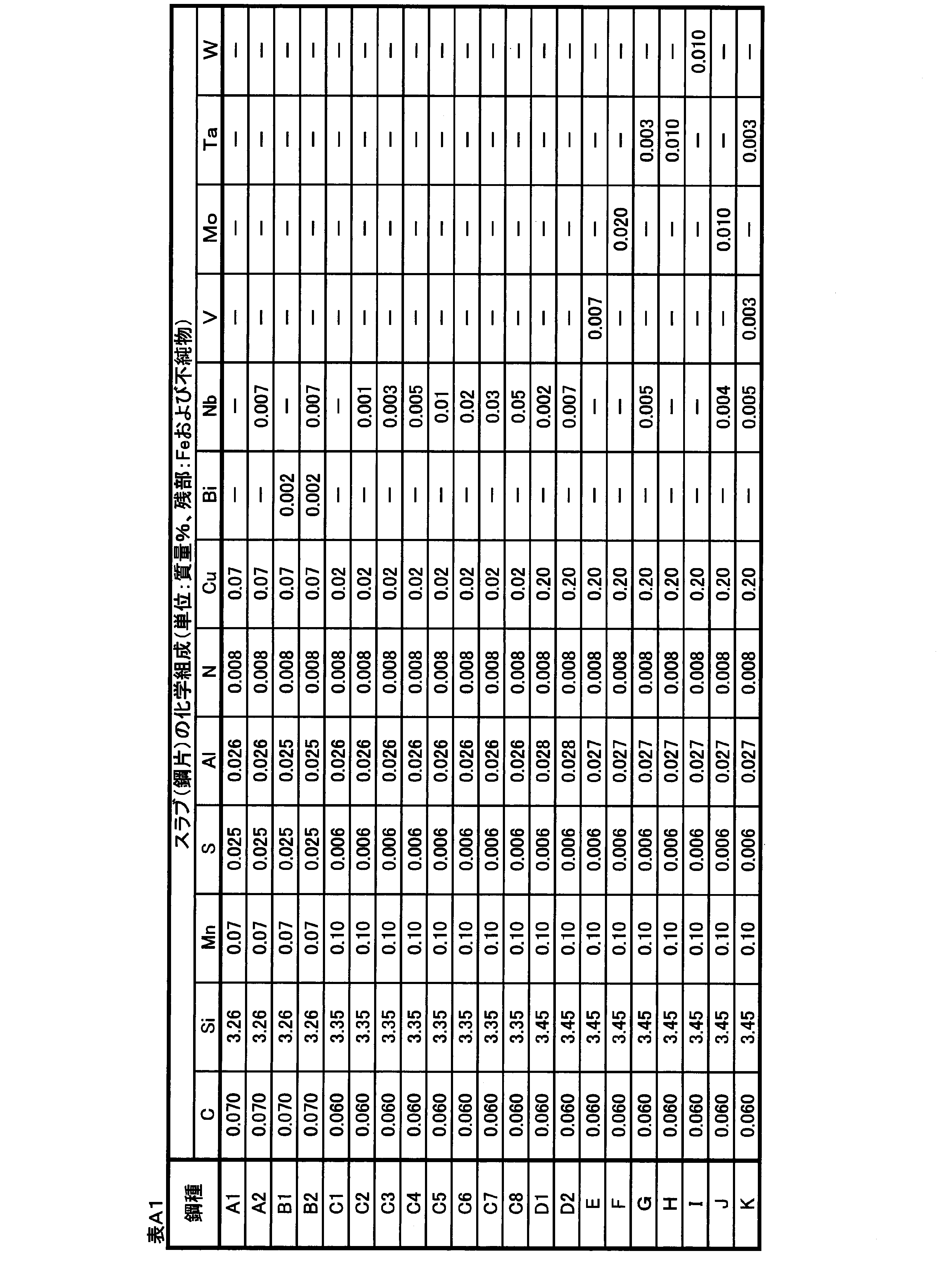


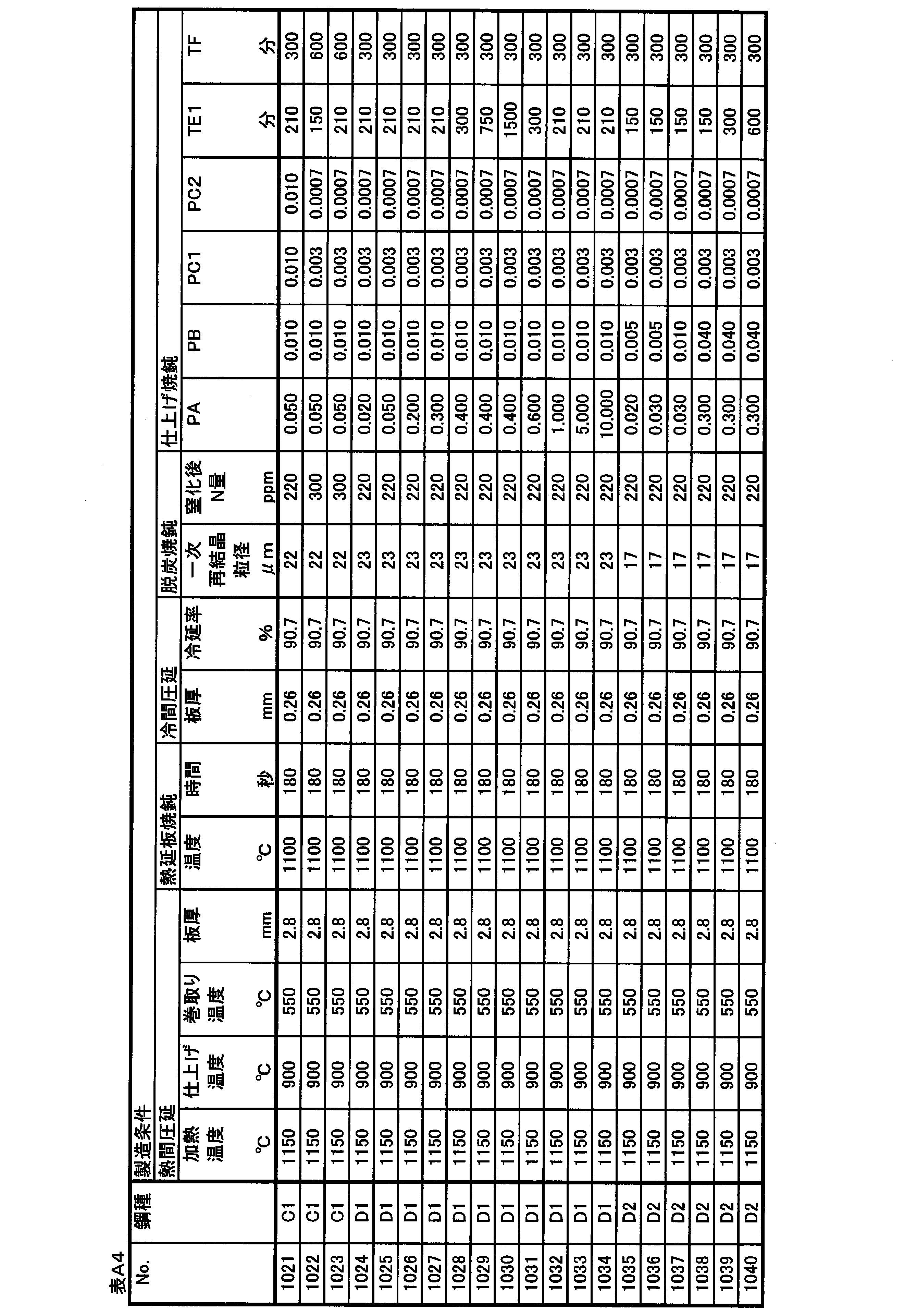

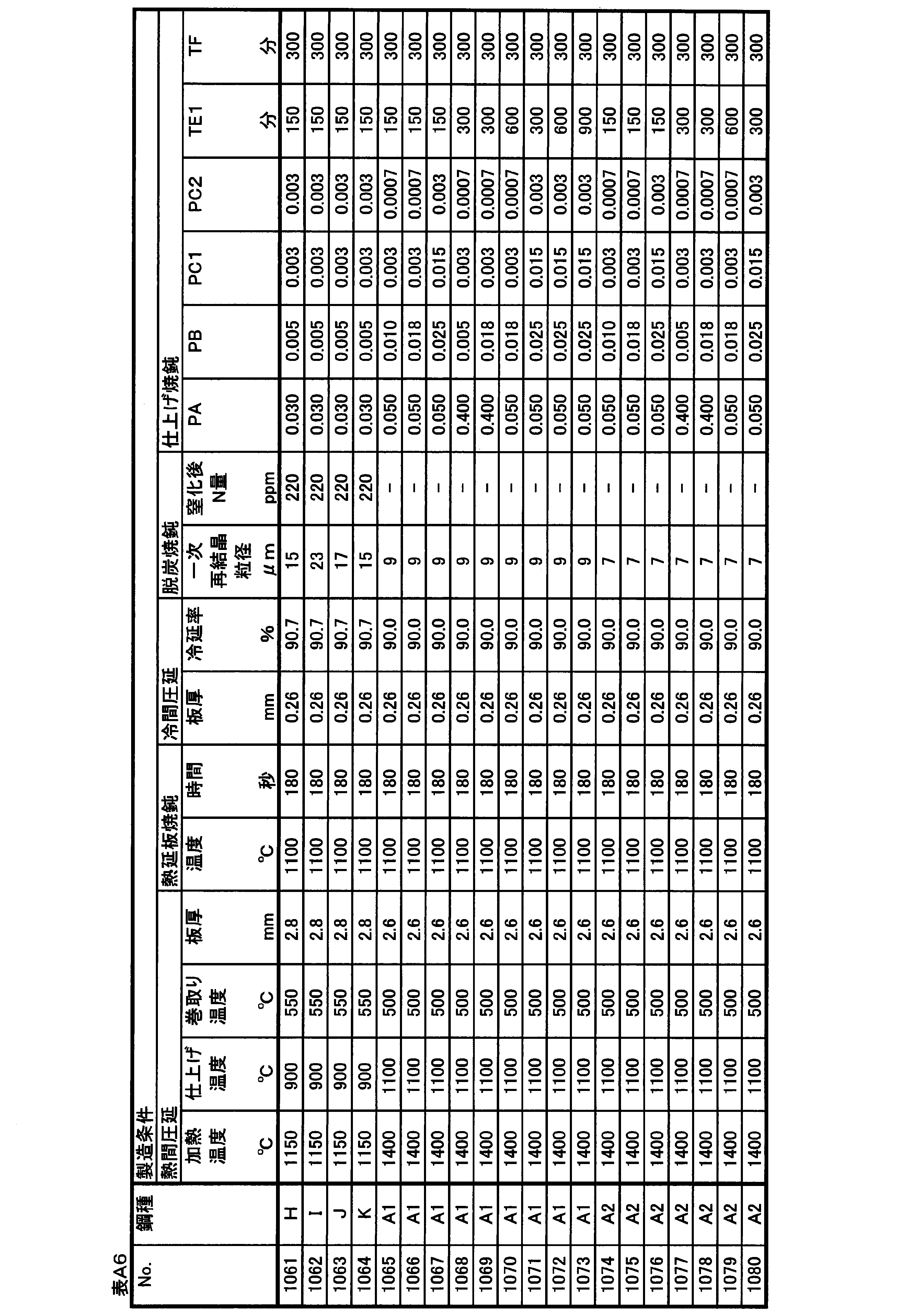

方向性電磁鋼板の結晶方位を上記の方法で測定した。この測定した各測定点の結晶方位からずれ角を特定し、このずれ角に基づいて隣接する2つの測定点間に存在する粒界を特定した。なお、間隔が1mmである2つの測定点で境界条件を判定したとき、「境界条件BAを満足する境界数」を「境界条件BBを満足する境界数」で割った値が1.15以上である場合に、「境界条件BAを満足し且つ境界条件BBを満足しない粒界」が存在すると判断し、且つ表中で「切り替え粒界」が存在すると表示した。なお、「境界条件BAを満足する境界数」とは、上記した表1のケースAおよび/またはケースBの粒界に対応し、「境界条件BBを満足する境界数」とは、ケースAの粒界に対応する。また、特定した粒界に基づいて平均結晶粒径を算出した。加えて、ずれ角θの絶対値の標準偏差σ(θ)を上記の方法で測定した。 (1) Crystal orientation of grain-oriented electrical steel sheet The crystal orientation of grain-oriented electrical steel sheet was measured by the above method. A shift angle was specified from the crystal orientation of each of the measured measurement points, and a grain boundary existing between two adjacent measurement points was specified based on the shift angle. When the boundary condition is determined at two measurement points with an interval of 1 mm, the value obtained by dividing the “number of boundaries satisfying the boundary condition BA” by the “number of boundaries satisfying the boundary condition BB” is 1.15 or more. In some cases, it was determined that "a grain boundary that satisfies the boundary condition BA and did not satisfy the boundary condition BB" was present, and that "switching grain boundary" was displayed in the table. The “number of boundaries satisfying the boundary condition BA” corresponds to the grain boundaries of the case A and / or case B in Table 1 described above, and the “number of boundaries satisfying the boundary condition BB” corresponds to Corresponds to grain boundaries. The average crystal grain size was calculated based on the specified grain boundaries. In addition, the standard deviation σ (θ) of the absolute value of the shift angle θ was measured by the above method.
方向性電磁鋼板の磁気特性は、JIS C 2556:2015に規定された単板磁気特性試験法(SST:Single Sheet Tester)に基づいて測定した。 (2) Magnetic properties of grain-oriented electrical steel sheets The magnetic properties of grain-oriented electrical steel sheets were measured based on a single-sheet magnetic property test method (SST: Single Sheet Tester) specified in JIS C 2556: 2015.
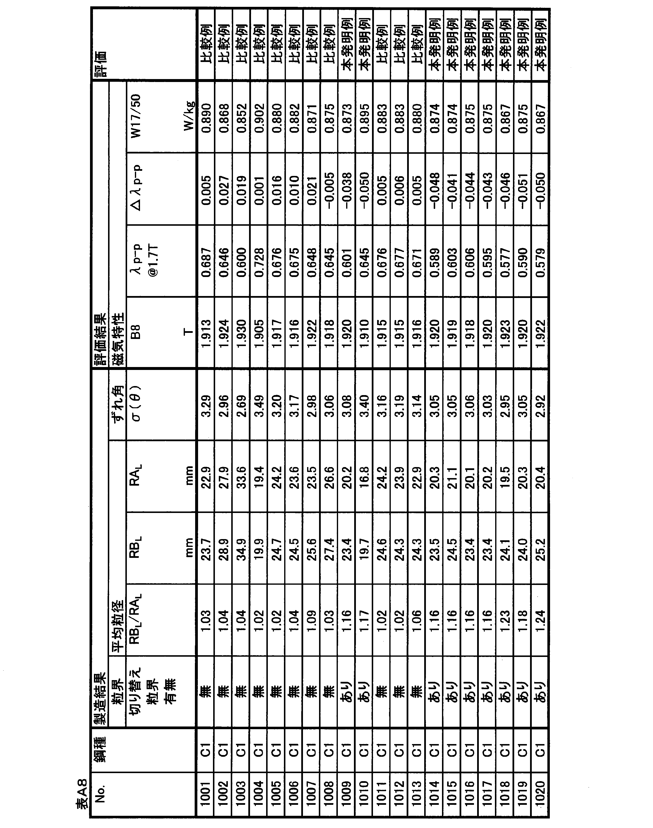
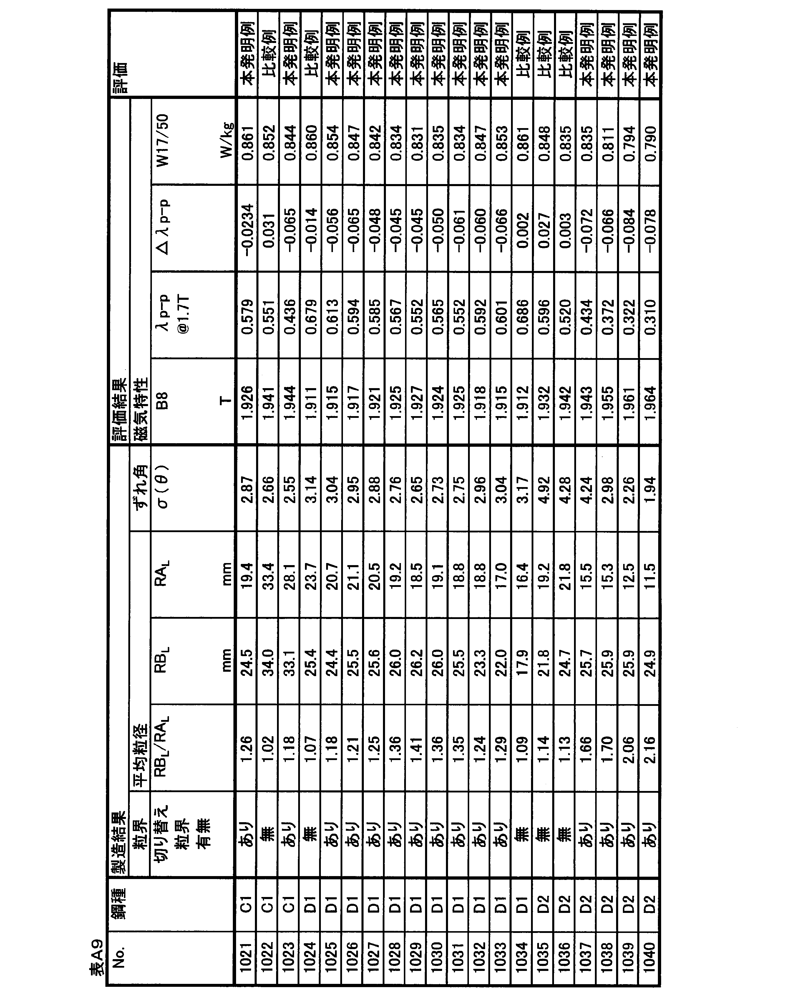
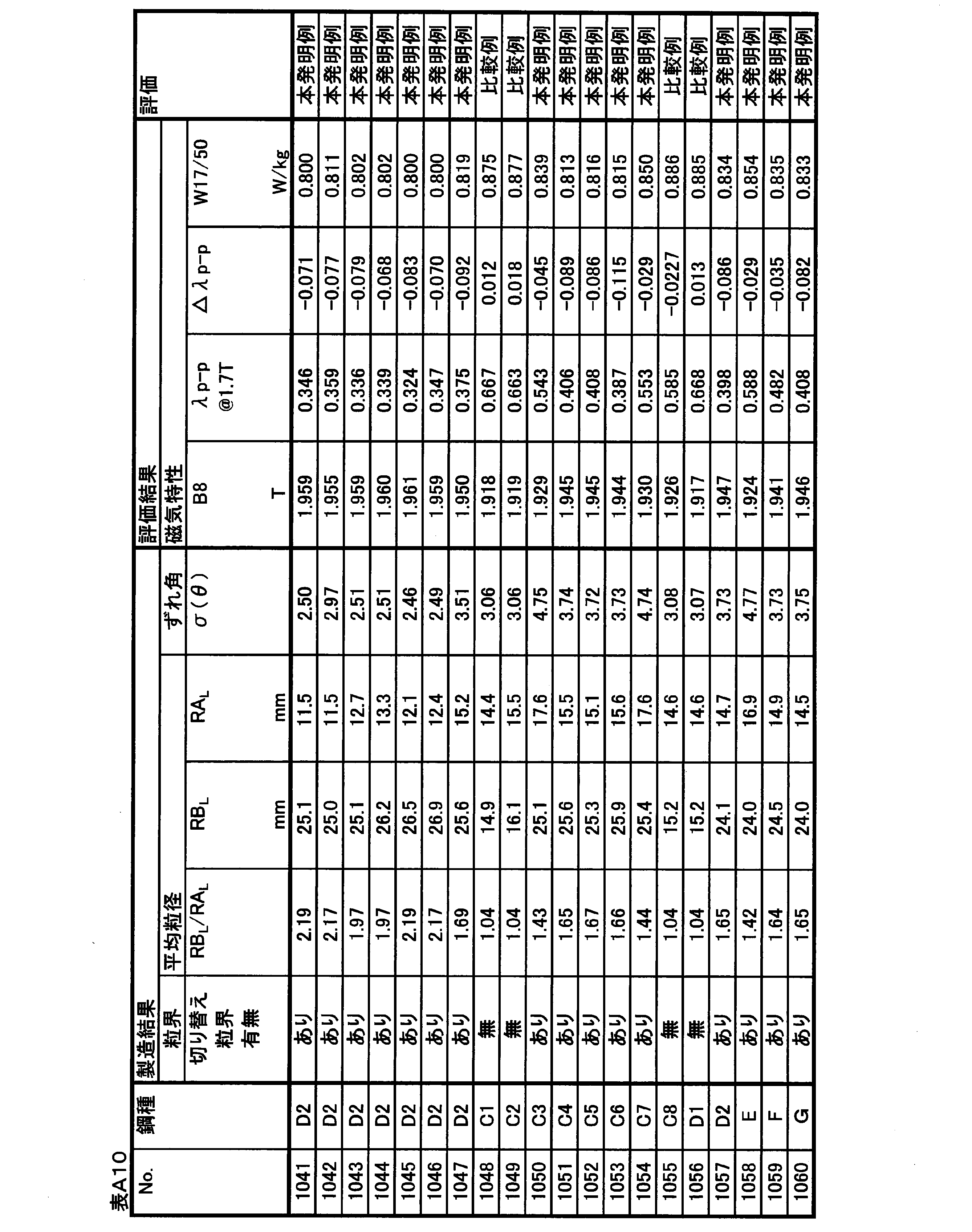


△λp-p=λp-p@1.7T-(11.68-5.75×B8) In the first embodiment, the technical effect will be described using magnetostriction (λp−p@1.7T). However, it is difficult to understand the superiority and inferiority of the effect simply by comparing the magnitude of the magnetostriction. For example, magnetostriction has a relatively strong correlation with magnetic flux density, and the higher the magnetic flux density, the lower the magnetostriction. Therefore, even if the absolute value of the magnetostriction is low, it is difficult to determine whether the effect of reducing the magnetostriction is obtained if the magnetic flux density of the evaluation material is sufficiently high. That is, the effect of reducing the magnetostriction needs to be determined in consideration of the correlation with the magnetic flux density. In this embodiment, the following △ λp-p is used as an index for magnetostriction evaluation.
Δλp-p=λp-p@1.7T- (11.68-5.75 × B 8 )
No.1001~1064は、スラブ加熱温度を低くして一次再結晶後の窒化によって二次再結晶の主要なインヒビターを形成するプロセスで製造した実施例である。 (Example manufactured by low-temperature slab heating process)
No. Examples 1001 to 1064 are examples manufactured by a process of forming a main inhibitor of secondary recrystallization by nitridation after primary recrystallization by lowering the slab heating temperature.
No.1001~1023は、Nbを含有しない鋼種を用いて、仕上げ焼鈍時に主にPA、PB、PC1、PC2、およびTE1の条件を変化させた実施例である。 (Examples of Nos. 1001 to 1023)
No. Examples 1001 to 1023 are examples in which the conditions of PA, PB, PC1, PC2, and TE1 are mainly changed at the time of finish annealing using a steel type not containing Nb.
No.1024~1034は、Nbを0.002%含有する鋼種を用いて、仕上げ焼鈍時に主にPAおよびTE1の条件を変化させた実施例である。 (Examples of Nos. 1024 to 1034)
No. Examples 1024 to 1034 are examples in which the conditions of PA and TE1 are mainly changed at the time of finish annealing using a steel type containing 0.002% of Nb.
No.1035~1047は、Nb含有量を0.006%とした実施例である。 (Examples of Nos. 1035 to 1047)
No. Examples 1035 to 1047 are examples in which the Nb content is 0.006%.
No.1048~1055は、TE1を200分未満の短時間とし、特にNb含有量の影響を確認した実施例である。 (Examples of Nos. 1048 to 1055)
No. Examples 1048 to 1055 are examples in which TE1 was set to a short time of less than 200 minutes and the influence of the Nb content was particularly confirmed.
No.1056~1064は、TE1を200分未満の短時間とし、Nb群元素の含有量の影響を確認した実施例である。 (Examples of Nos. 1056 to 1064)
No. Examples 1056 to 1064 are examples in which TE1 was set to a short time of less than 200 minutes and the effect of the content of the Nb group element was confirmed.
No.1065~1100は、スラブ加熱温度を高くしてスラブ加熱中に十分に溶解したMnSを後工程で再析出させて主要なインヒビターとして活用するプロセスで製造した実施例である。 (Example manufactured by high-temperature slab heating process)
No. Nos. 1065 to 1100 are examples manufactured by a process in which the slab heating temperature is increased and MnS sufficiently dissolved during slab heating is reprecipitated in a later step and used as a main inhibitor.
表B1に示す化学組成を有するスラブを素材として、表B2に示す化学組成を有する方向性電磁鋼板を製造とした。なお、化学組成の測定方法や、表中での記述方法は上記の実施例1と同じである。 (Example 2)
Using a slab having the chemical composition shown in Table B1 as a raw material, a grain-oriented electrical steel sheet having the chemical composition shown in Table B2 was produced. The method of measuring the chemical composition and the method of description in the table are the same as those in Example 1 described above.
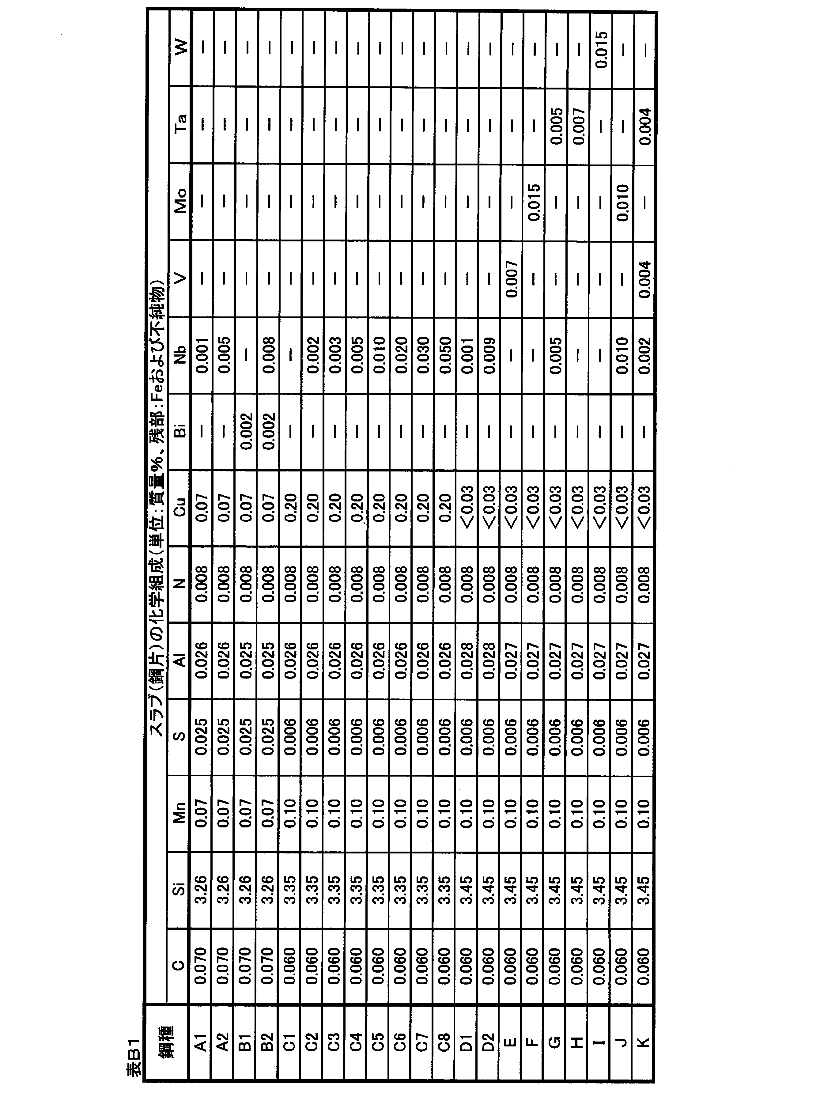
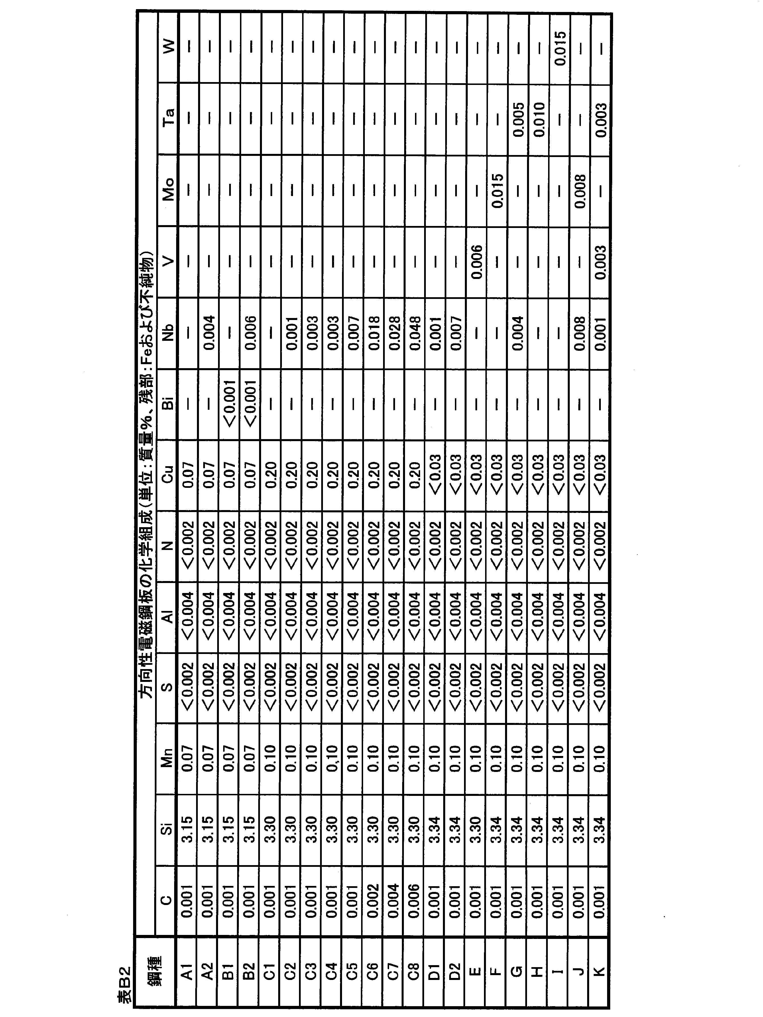
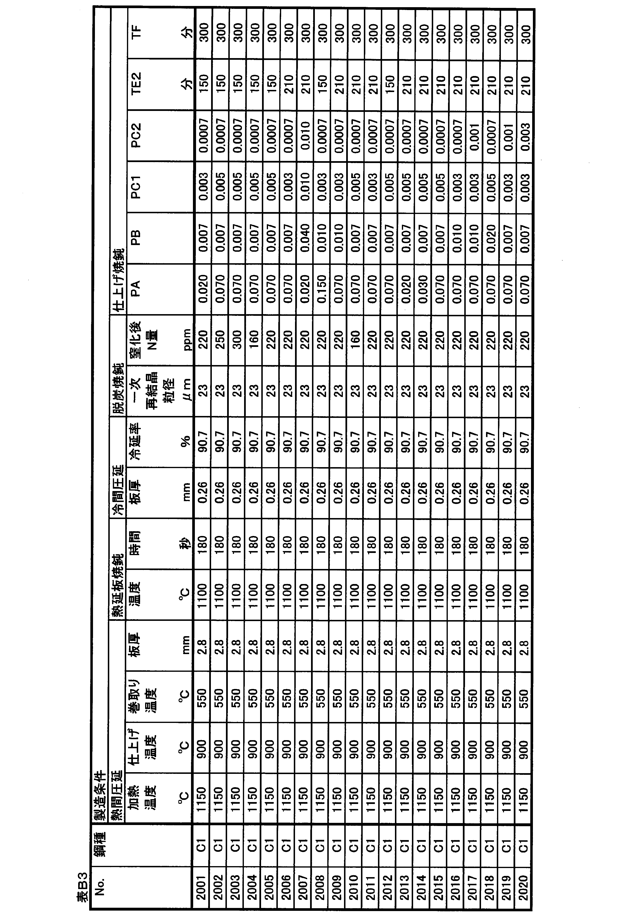

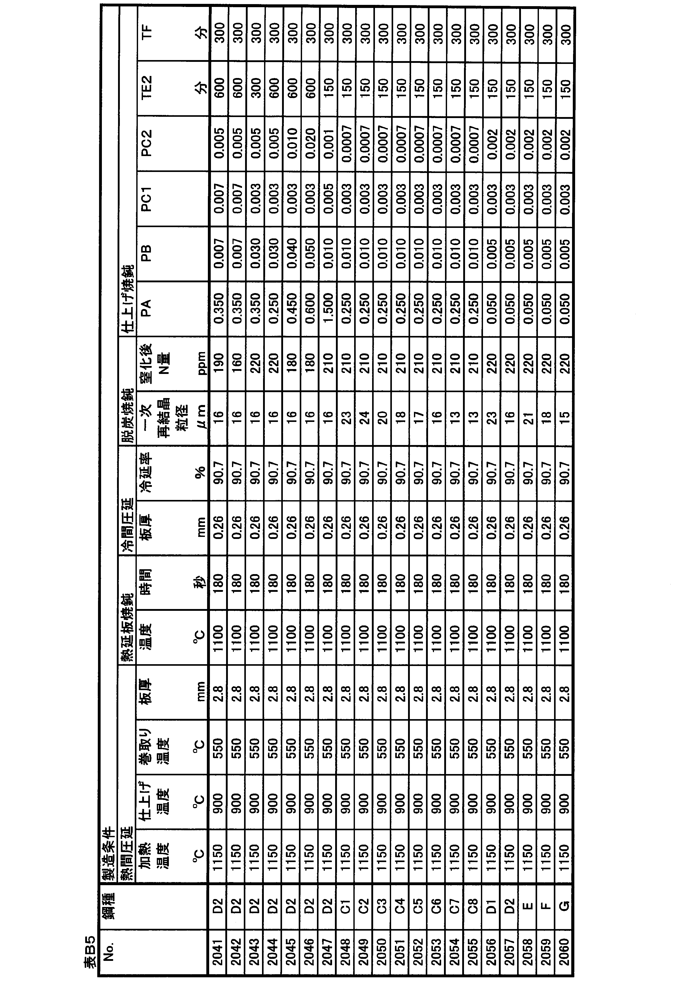
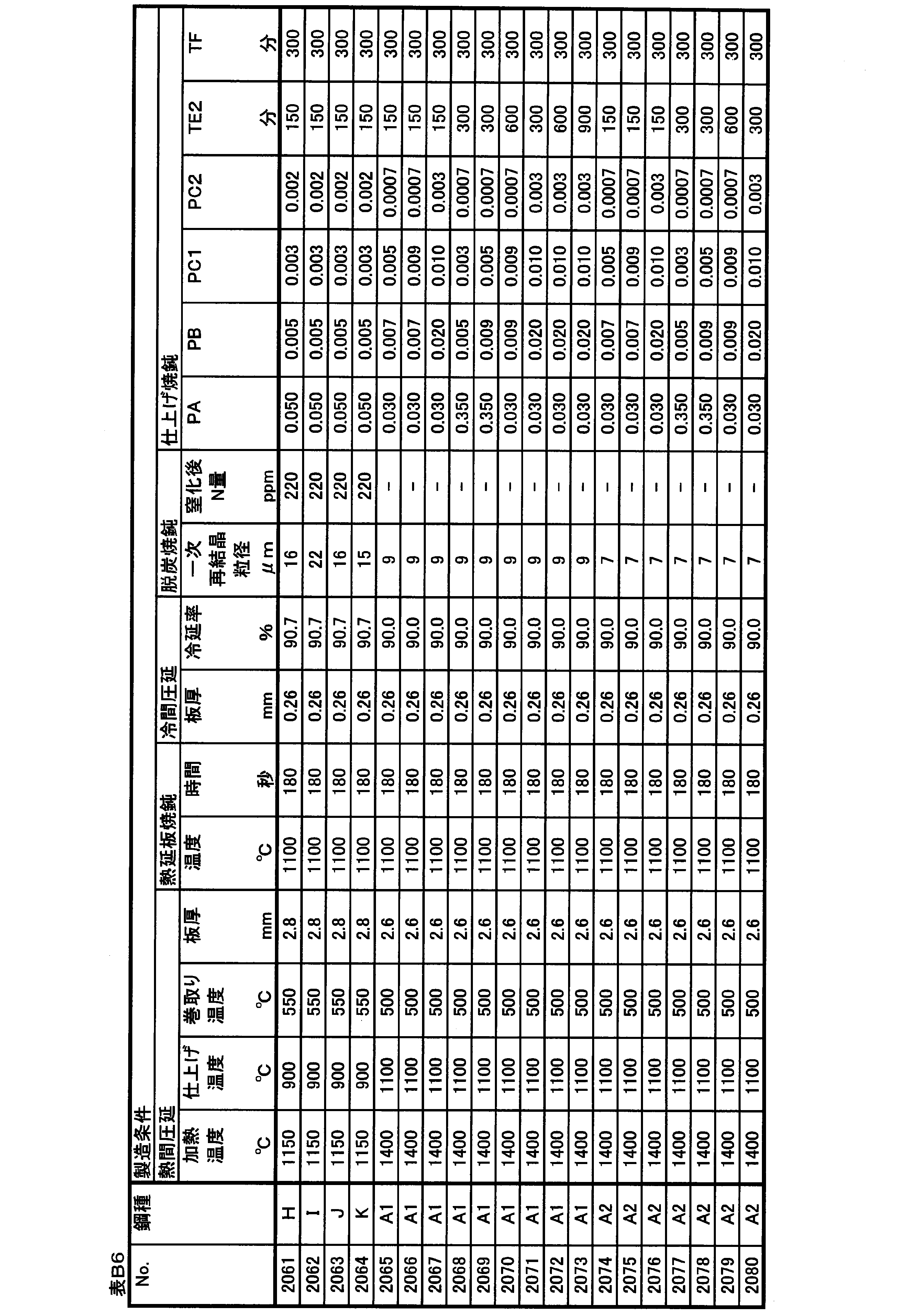
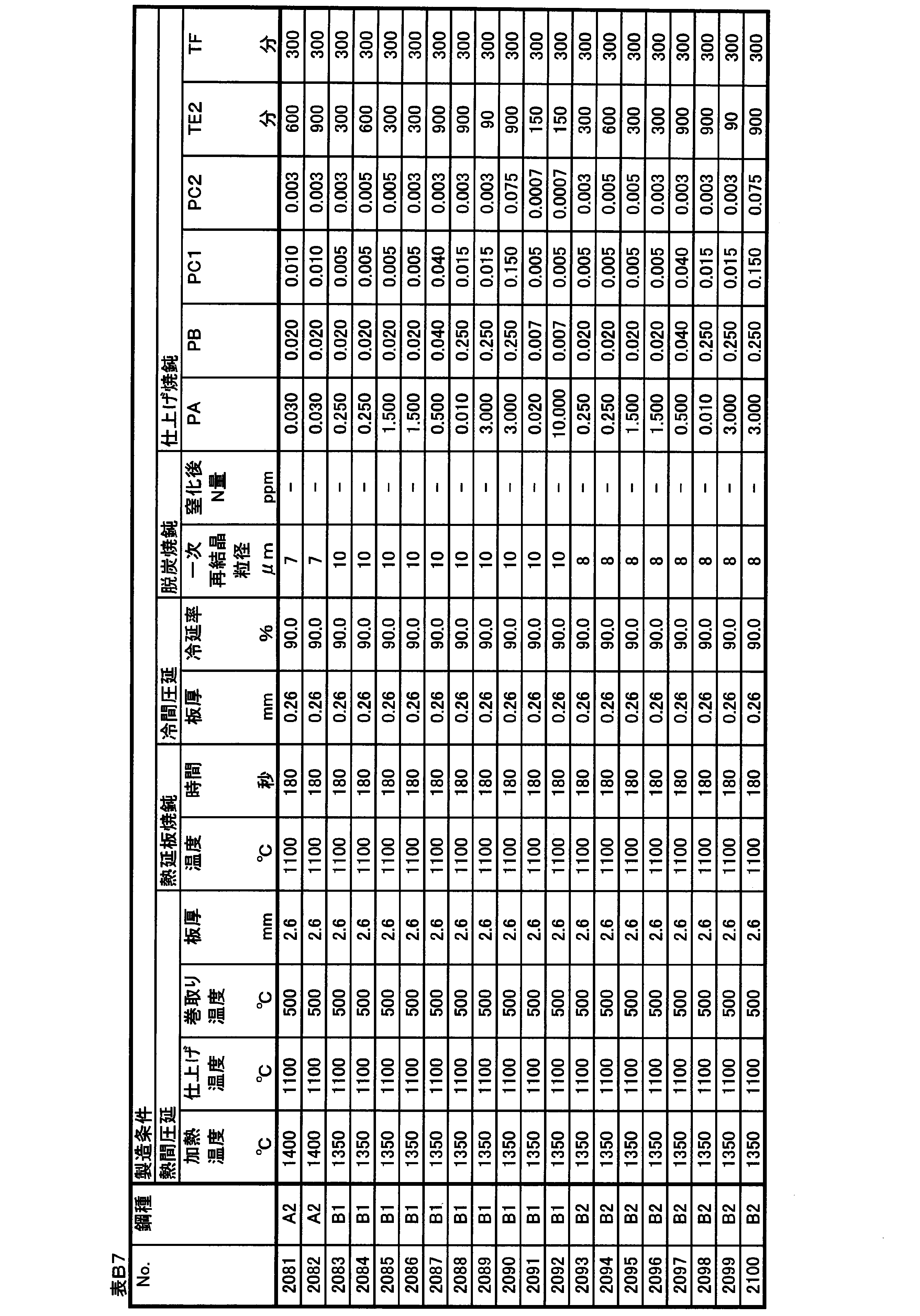
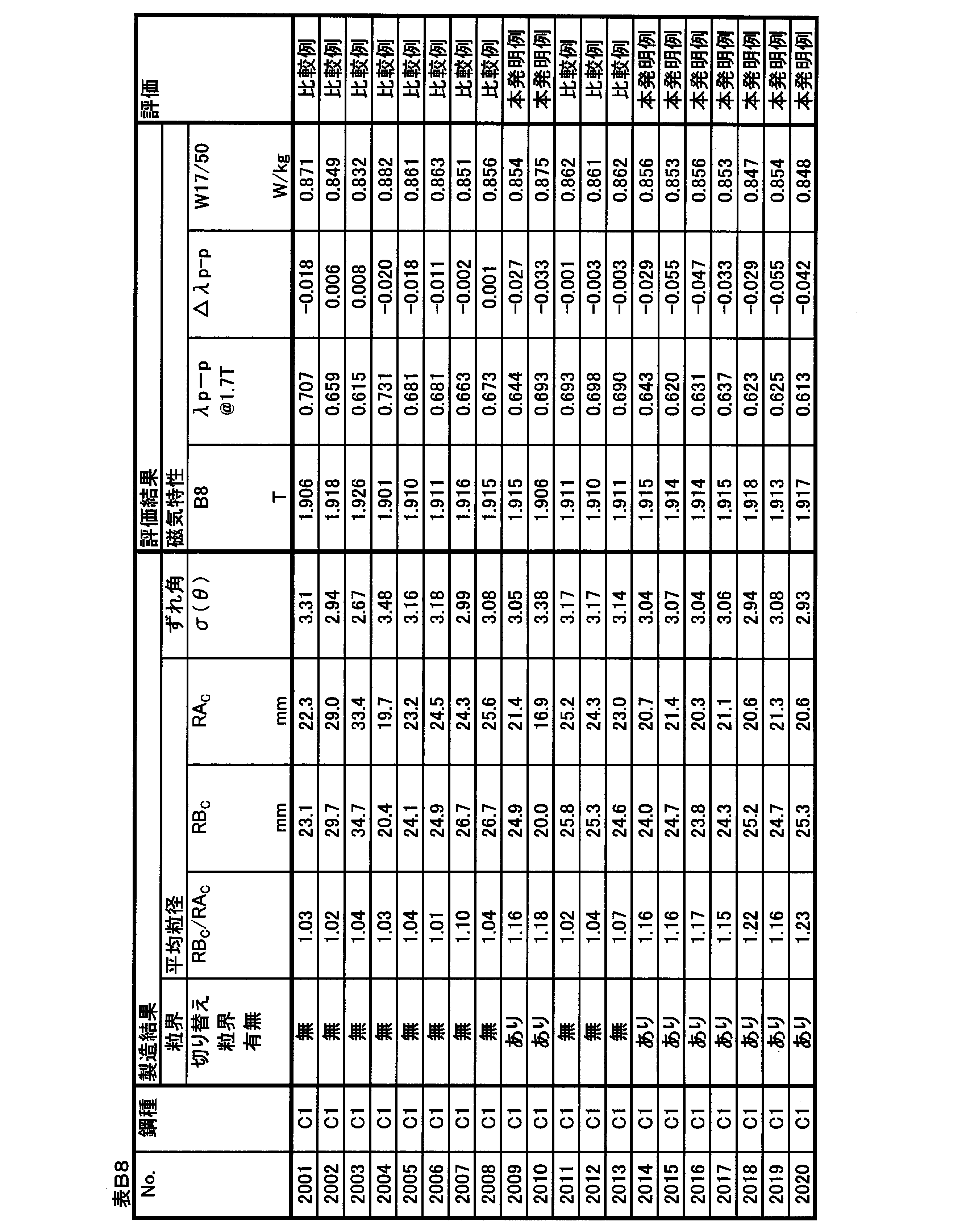
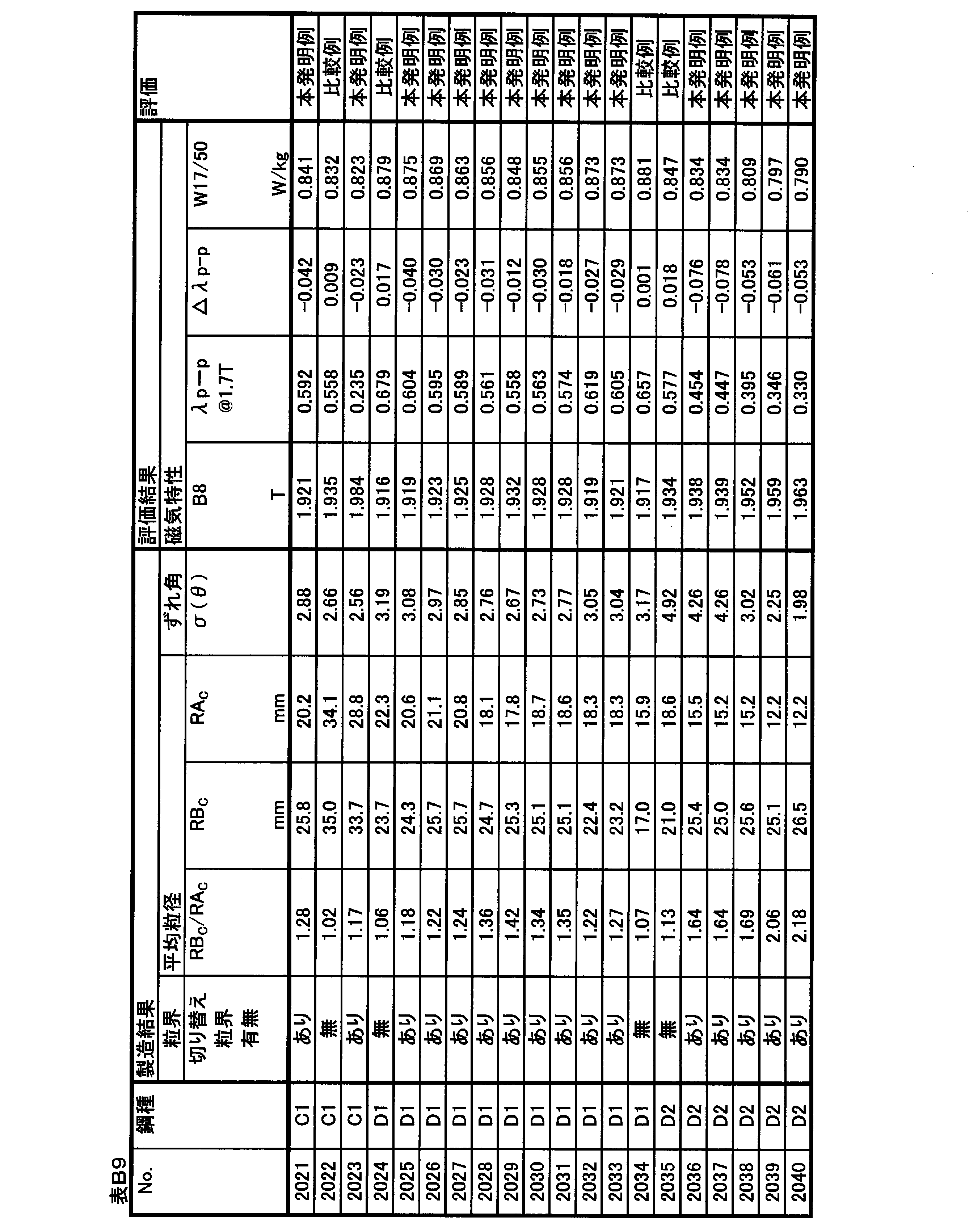
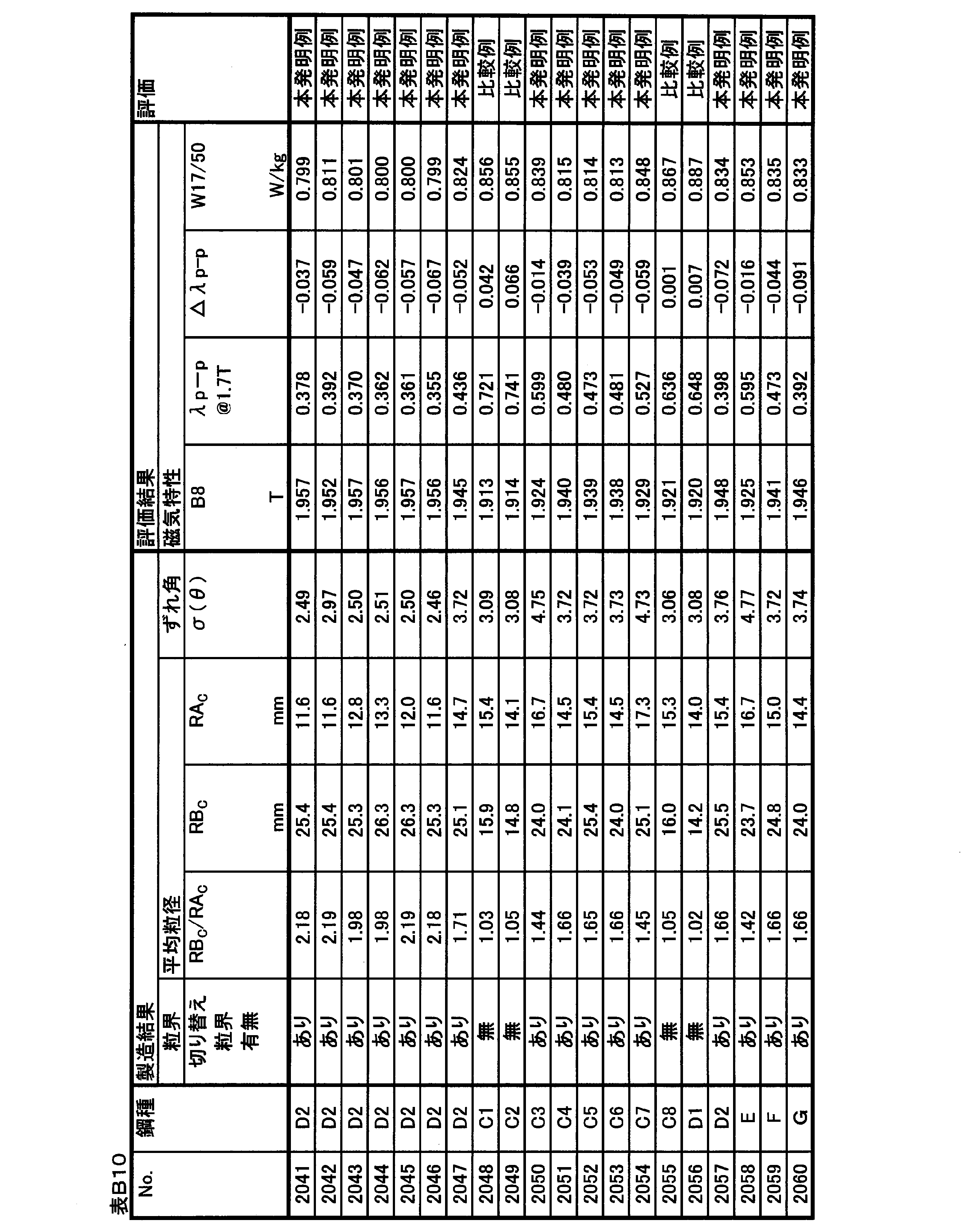


△λp-p=λp-p@1.7T-(12.16-6.00×B8) In the second embodiment, the following △ λp-p is used as an index for evaluating magnetostriction. The reason for using the index of magnetostriction evaluation is the same as that of the first embodiment.
Δλp-p=λp-p@1.7T- (12.16-6.00 × B 8 )
No.2001~2064は、スラブ加熱温度を低くして一次再結晶後の窒化によって二次再結晶の主要なインヒビターを形成するプロセスで製造した実施例である。 (Example manufactured by low-temperature slab heating process)
No. Examples 2001 to 2064 are examples manufactured by a process of forming a main inhibitor of secondary recrystallization by nitriding after primary recrystallization by lowering the slab heating temperature.
No.2001~2023は、Nbを含有しない鋼種を用いて、仕上げ焼鈍時に主にPA、PB、PC1、PC2、およびTE2の条件変化させた実施例である。 (Examples of Nos. 2001 to 2023)
No. Examples 2001 to 2023 are examples in which the conditions of PA, PB, PC1, PC2, and TE2 are mainly changed at the time of finish annealing using a steel type containing no Nb.
No.2024~2034は、Nbを0.001%含有する鋼種を用いて、仕上げ焼鈍時に主にPAおよびTE2の条件を変化させた実施例である。 (Examples of Nos. 2024 to 2034)
No. Examples 2024 to 2034 are examples in which the conditions of PA and TE2 are mainly changed at the time of finish annealing using a steel type containing 0.001% of Nb.
No.2035~2047は、Nb含有量を0.007%とした実施例である。 (Examples of Nos. 2035 to 2047)
No. 2035 to 2047 are Examples in which the Nb content is 0.007%.
No.2048~2055は、TE2を200分未満の短時間とし、特にNb含有量の影響を確認した実施例である。 (Examples of Nos. 2048 to 2055)
No. 2048 to 2055 are Examples in which TE2 was set to a short time of less than 200 minutes and the influence of the Nb content was particularly confirmed.
No.2056~2064は、TE2を200分未満の短時間とし、Nb群元素の含有量の影響を確認した実施例である。 (Examples of Nos. 2056 to 2064)
No. Examples 2056 to 2064 are examples in which TE2 was set to a short time of less than 200 minutes and the effect of the content of the Nb group element was confirmed.
No.2065~2100は、スラブ加熱温度を高くしてスラブ加熱中に十分に溶解したMnSを後工程で再析出させて主要なインヒビターとして活用するプロセスで製造した実施例である。 (Example manufactured by high-temperature slab heating process)
No. 2065 to 2100 are examples produced by a process in which the slab heating temperature is increased and MnS sufficiently dissolved during slab heating is reprecipitated in a later step and used as a main inhibitor.
表C1に示す化学組成を有するスラブを素材として、表C2に示す化学組成を有する方向性電磁鋼板を製造とした。なお、化学組成の測定方法や、表中での記述方法は上記の実施例1と同じである。 (Example 3)
Using a slab having the chemical composition shown in Table C1 as a raw material, a grain-oriented electrical steel sheet having the chemical composition shown in Table C2 was produced. The method of measuring the chemical composition and the method of description in the table are the same as those in Example 1 described above.

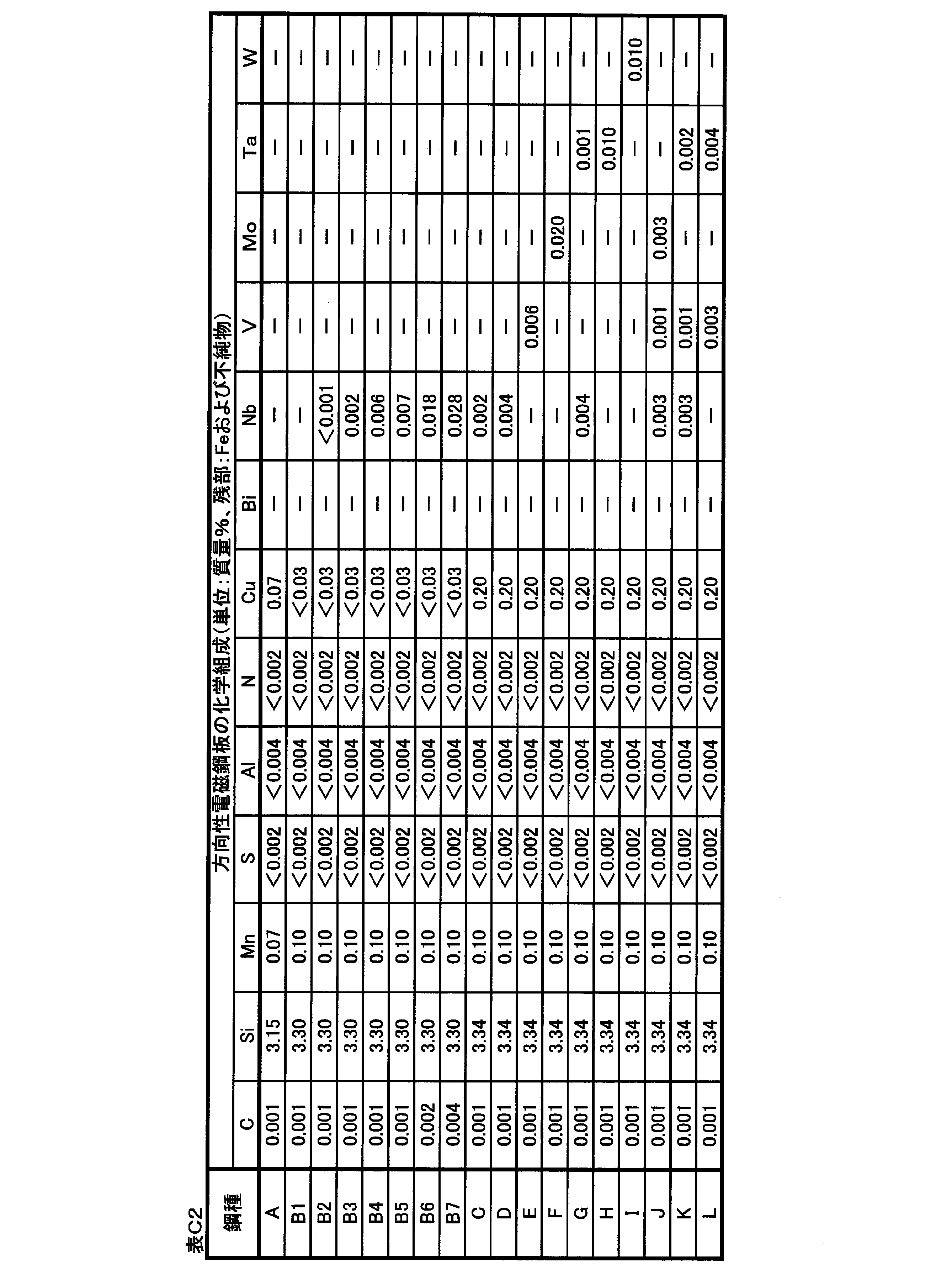
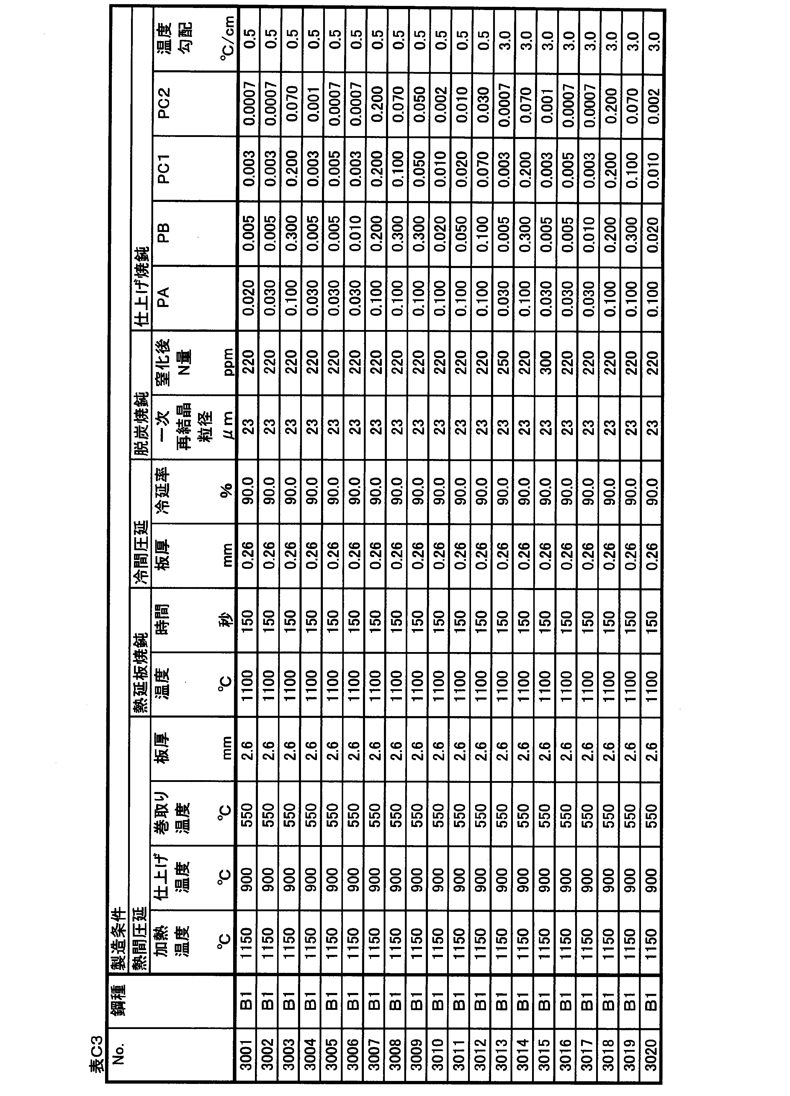

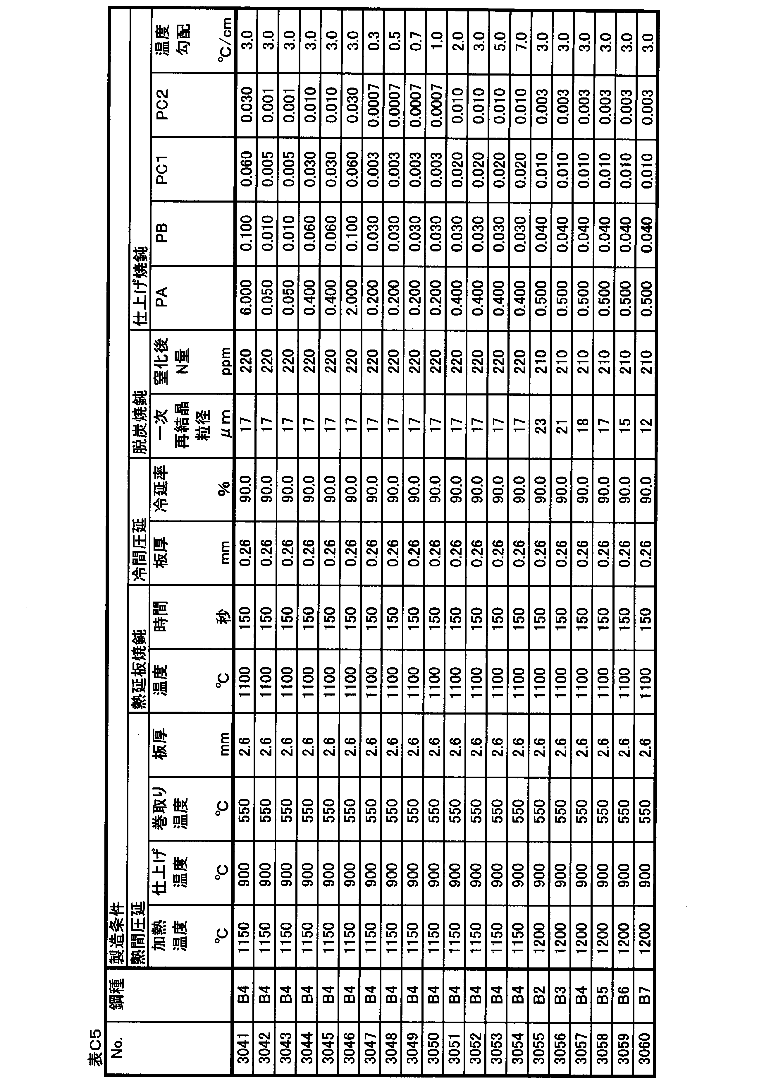
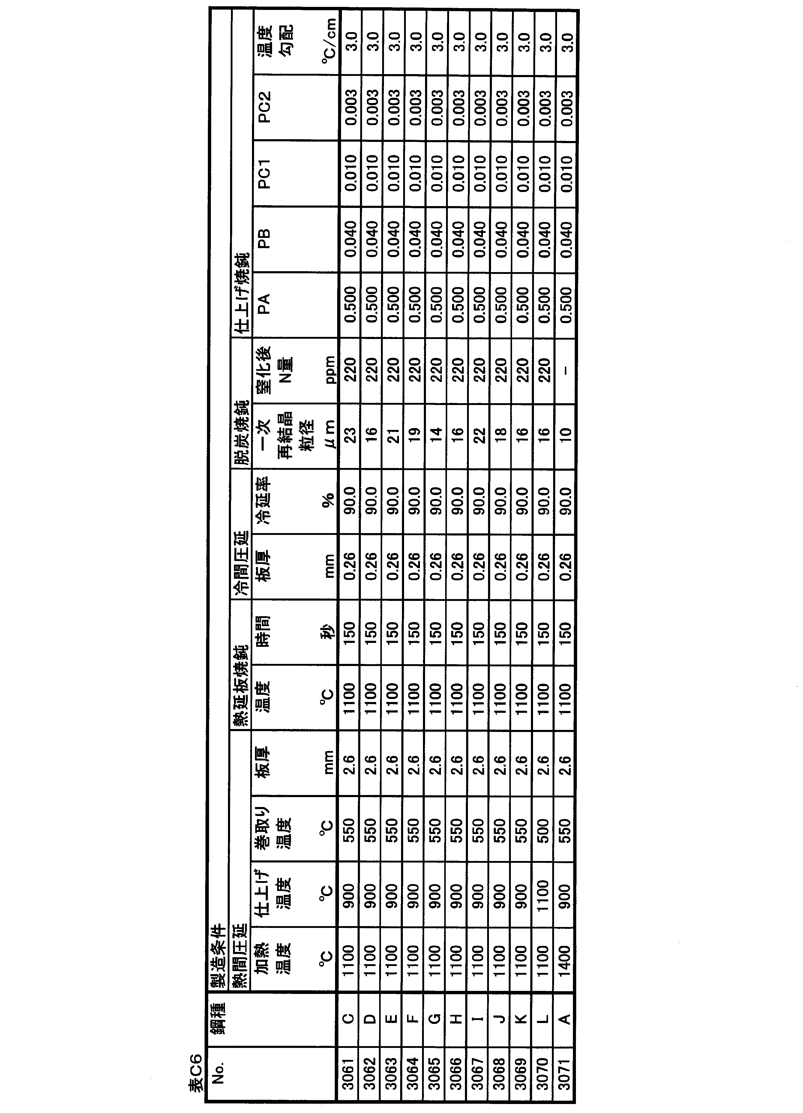
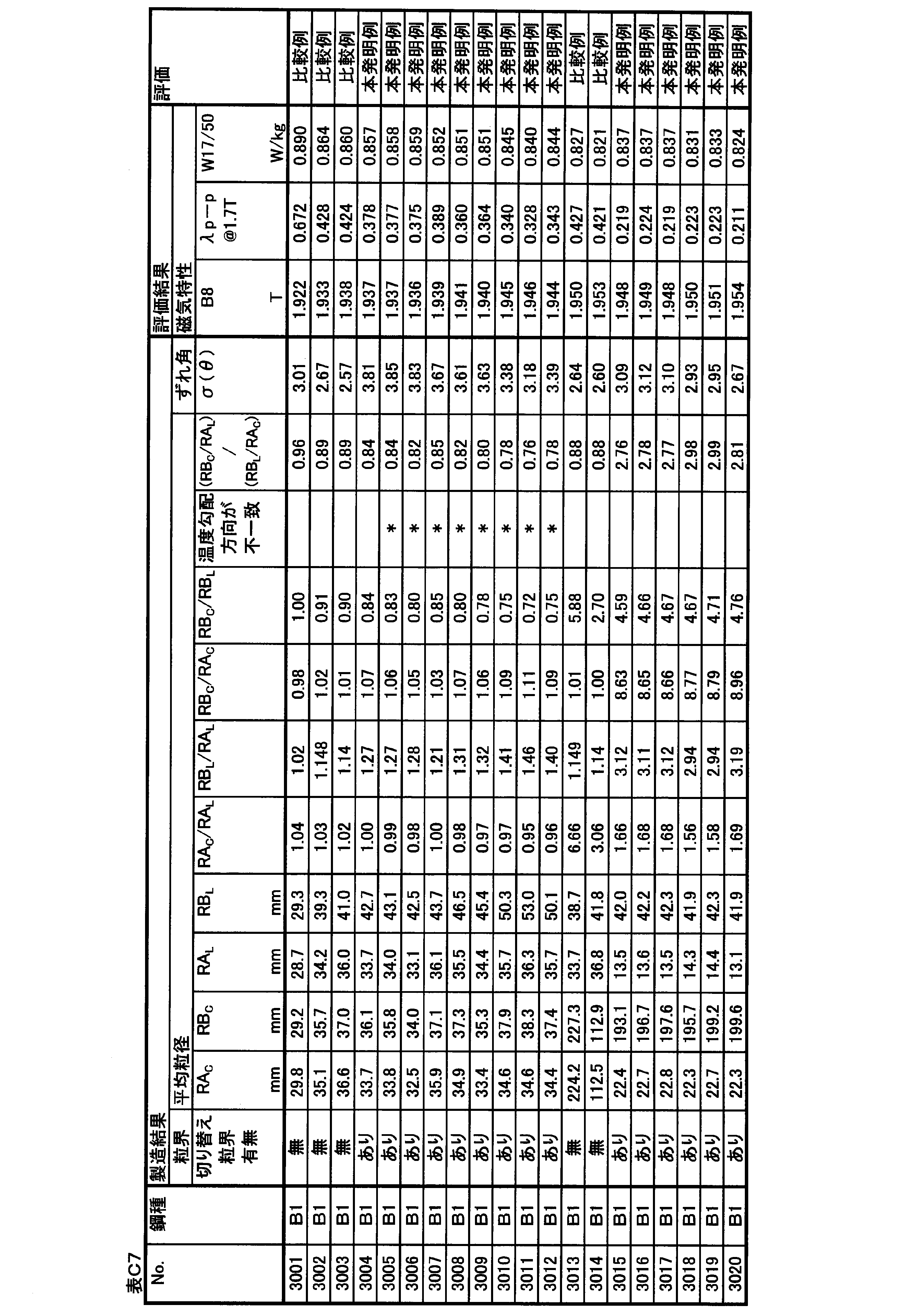
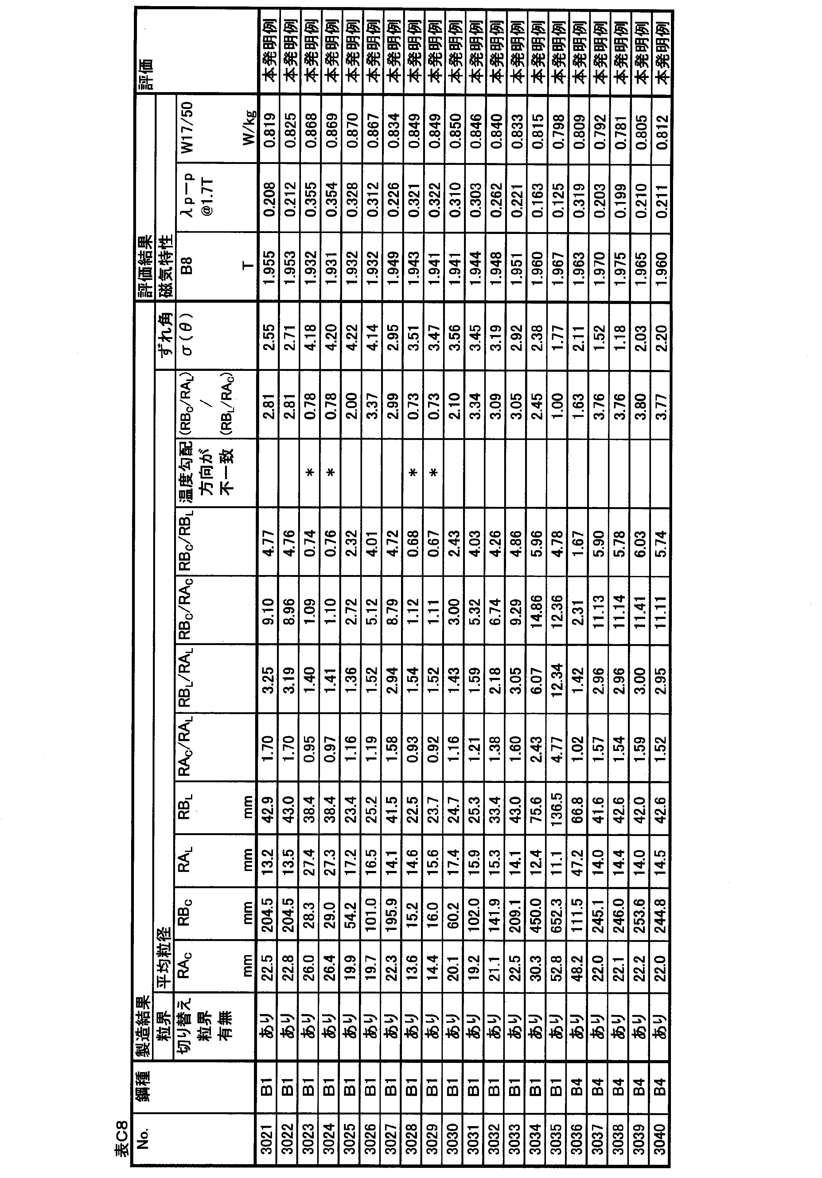
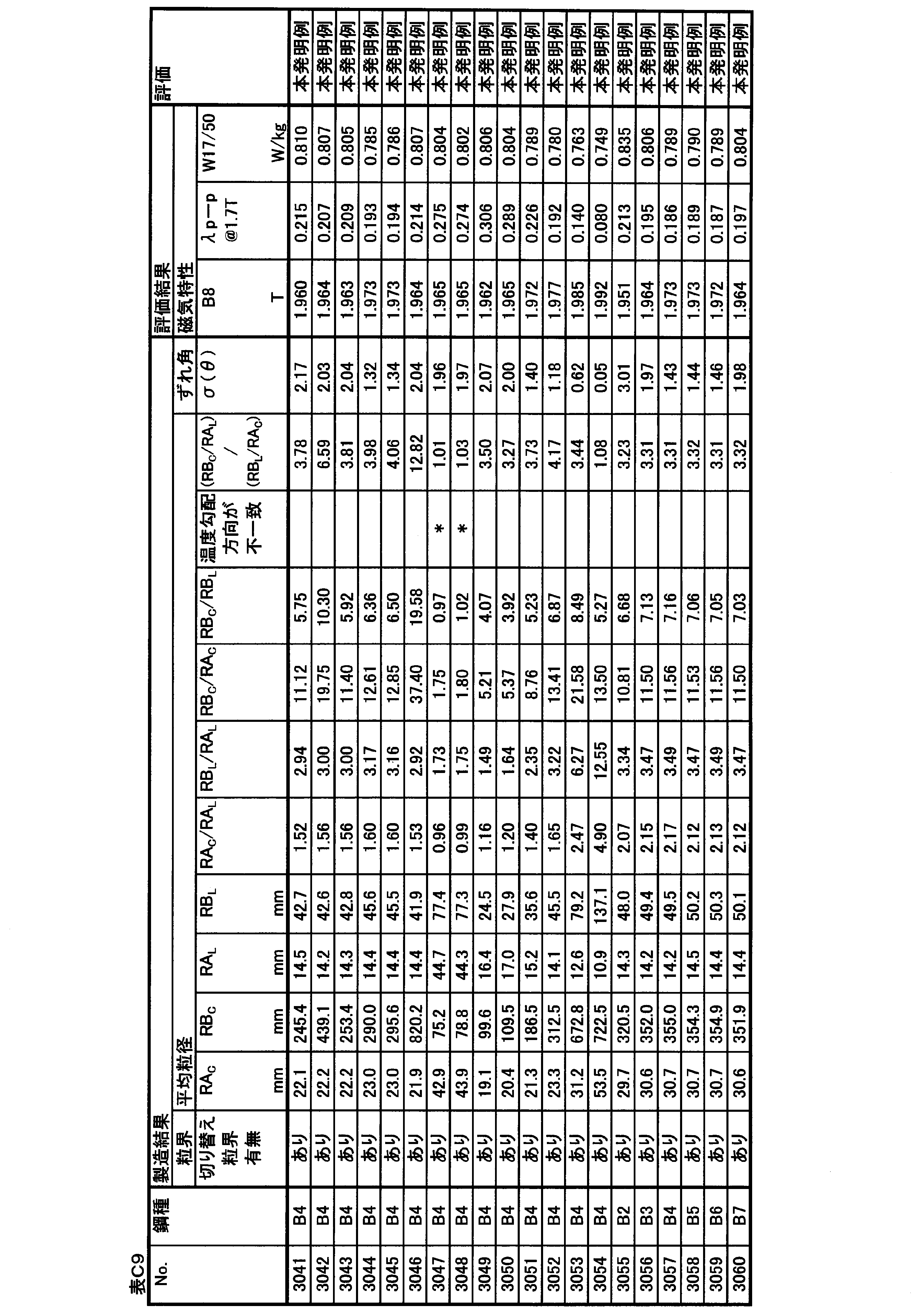

No.3001~3070は、スラブ加熱温度を低くして一次再結晶後の窒化によって二次再結晶の主要なインヒビターを形成するプロセスで製造した実施例である。 (Example manufactured by low-temperature slab heating process)
No. Examples 3001 to 3070 are examples manufactured by a process of forming a main inhibitor of secondary recrystallization by nitridation after primary recrystallization by lowering the slab heating temperature.
No.3001~3035は、Nbを含有しない鋼種を用いて、仕上げ焼鈍時に主にPA、PB、PC1、PC2、および温度勾配の条件を変化させた実施例である。 (Examples of Nos. 3001 to 3035)
No. Examples 3001 to 3035 are examples in which the conditions of PA, PB, PC1, PC2, and the temperature gradient are mainly changed at the time of finish annealing using a steel type not containing Nb.
No.3036~3070は、スラブ時点でNb群元素を含有する鋼種を用いて、仕上げ焼鈍時に主にPA、PB、PC1、PC2、および温度勾配の条件を変化させた実施例である。 (Examples of Nos. 3036 to 3070)
No. Examples 3036 to 3070 are examples in which the conditions of PA, PB, PC1, PC2, and the temperature gradient were mainly changed at the time of finish annealing using a steel type containing an Nb group element at the time of slab.
No.3071は、スラブ加熱温度を高くしてスラブ加熱中に十分に溶解したMnSを後工程で再析出させて主要なインヒビターとして活用するプロセスで製造した実施例である。 (Example of No. 3071)
No. 3071 is an embodiment manufactured by a process in which the slab heating temperature is increased and MnS sufficiently dissolved during slab heating is reprecipitated in a later step and used as a main inhibitor.
表D1に示す化学組成を有するスラブを素材として、表D2に示す化学組成を有する方向性電磁鋼板を製造した。なお、化学組成の測定方法や、表中での記述方法は上記の実施例1と同じである。 (Example 4)
Grain-oriented electrical steel sheets having the chemical composition shown in Table D2 were produced from slabs having the chemical composition shown in Table D1. The method of measuring the chemical composition and the method of description in the table are the same as those in Example 1 described above.


表E1に示す化学組成を有するスラブを素材として、表E2に示す化学組成を有する方向性電磁鋼板(珪素鋼板)を製造した。なお、化学組成の測定方法や、表中での記述方法は上記の実施例1と同じである。 (Example 5)
Grain-oriented electrical steel sheets (silicon steel sheets) having the chemical composition shown in Table E2 were manufactured from slabs having the chemical composition shown in Table E1. The method of measuring the chemical composition and the method of description in the table are the same as those in Example 1 described above.
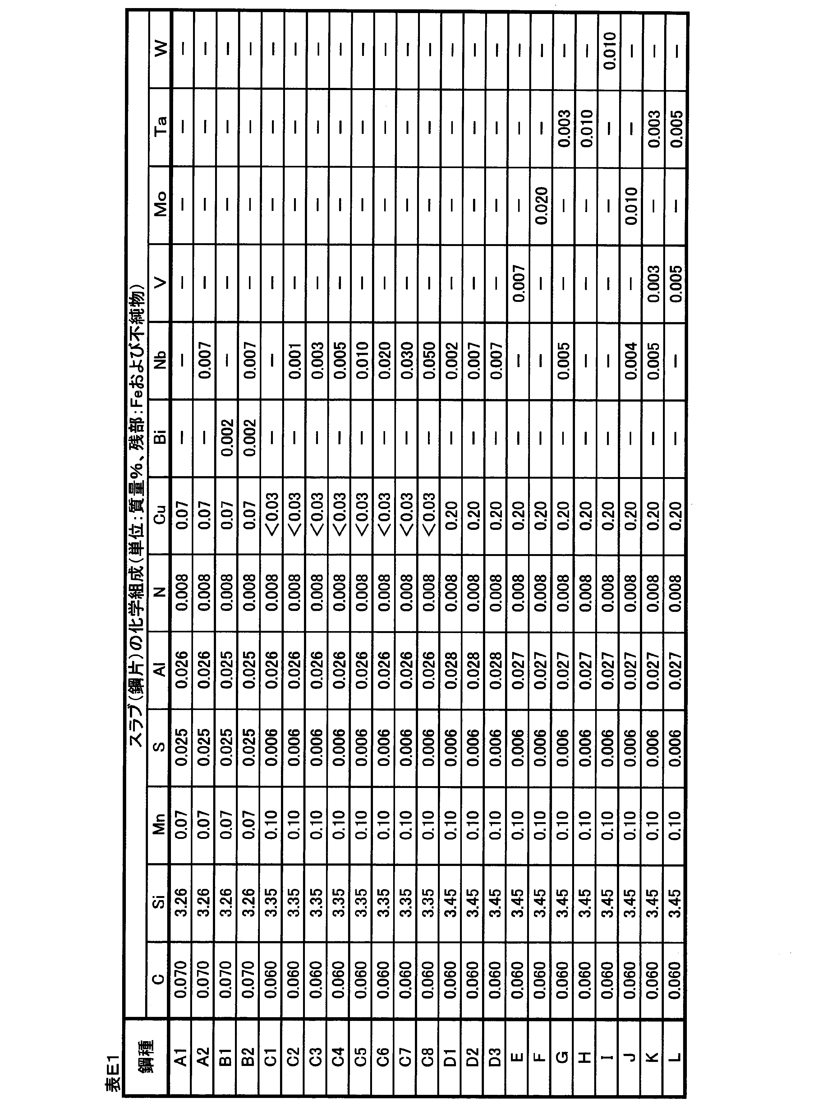

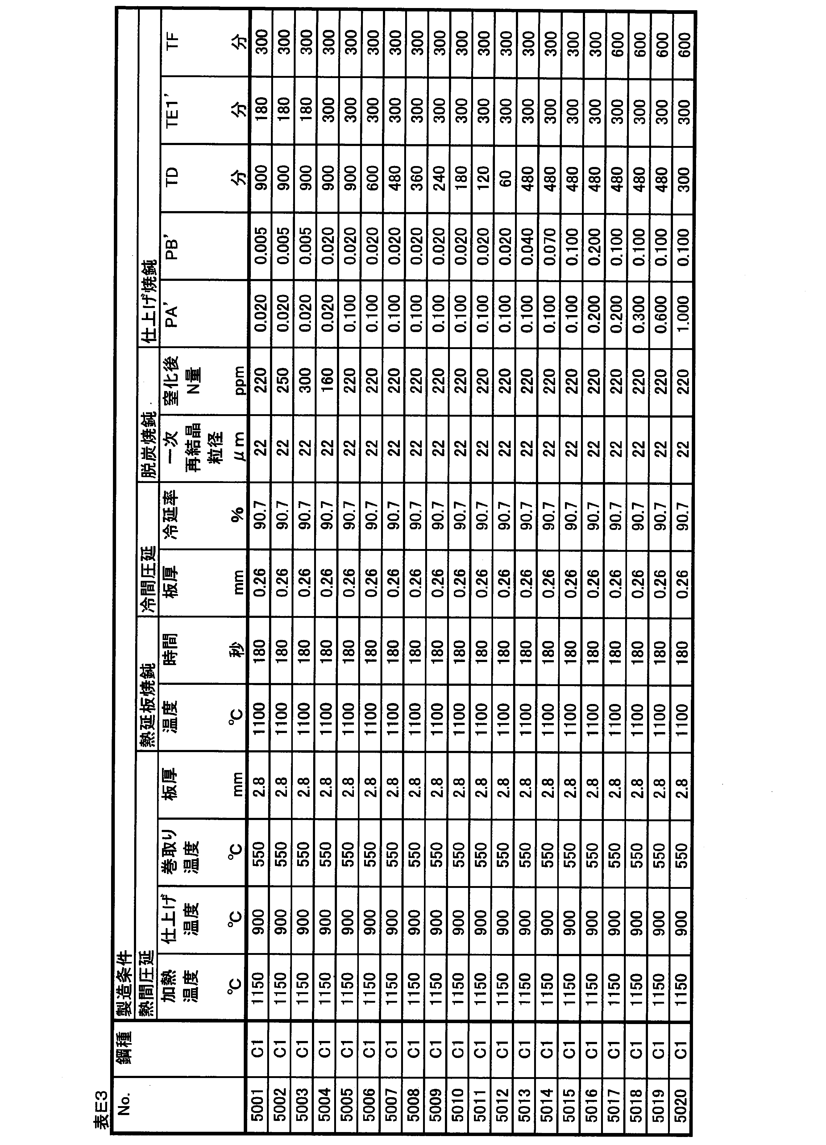

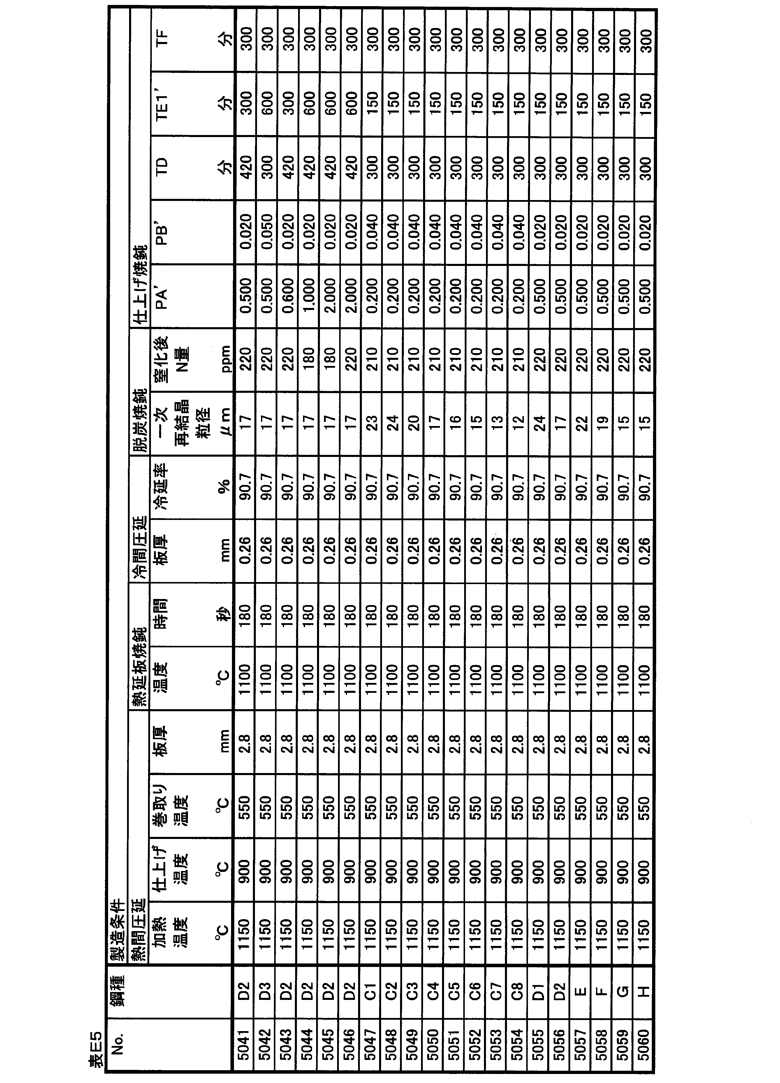
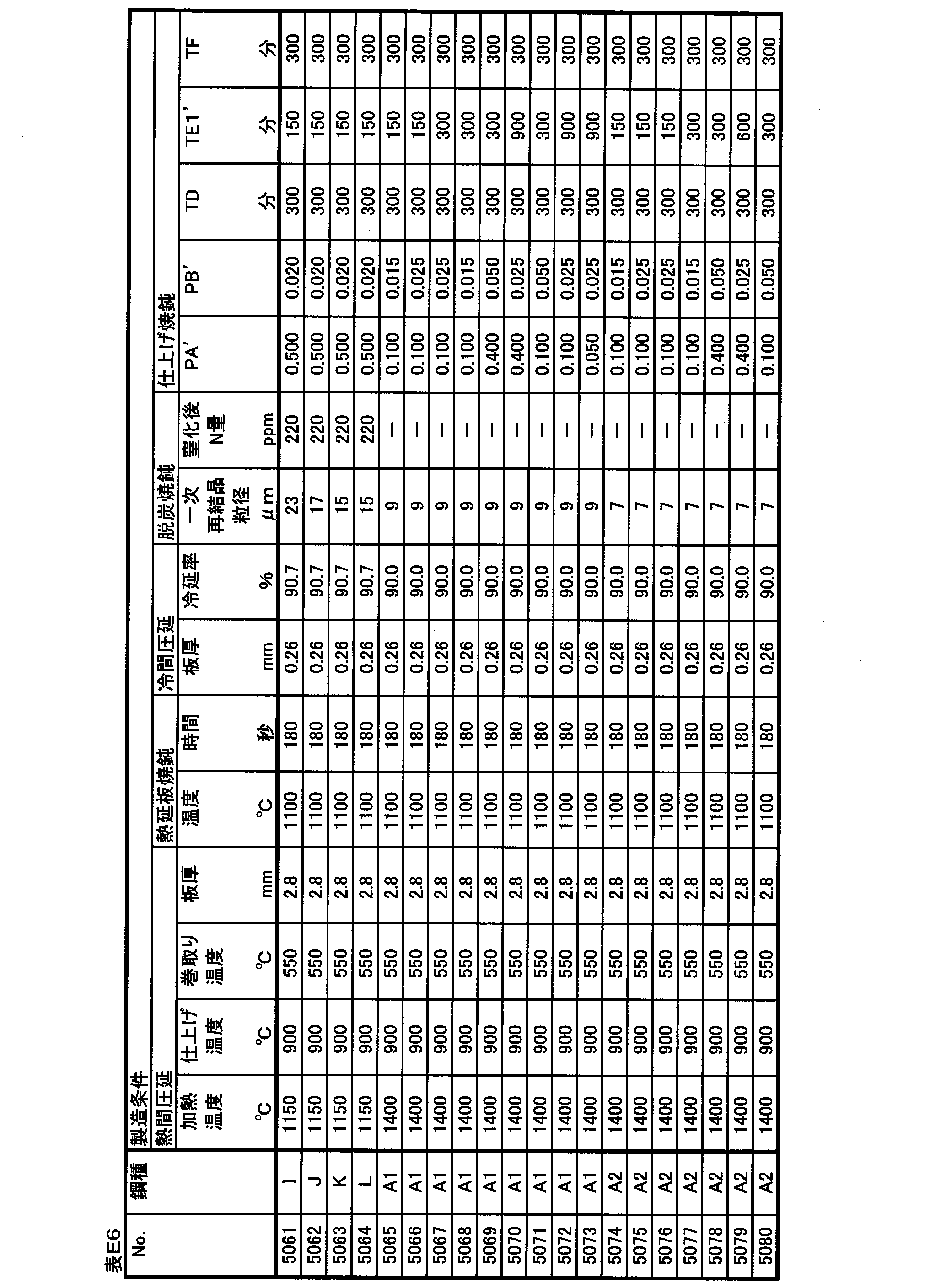
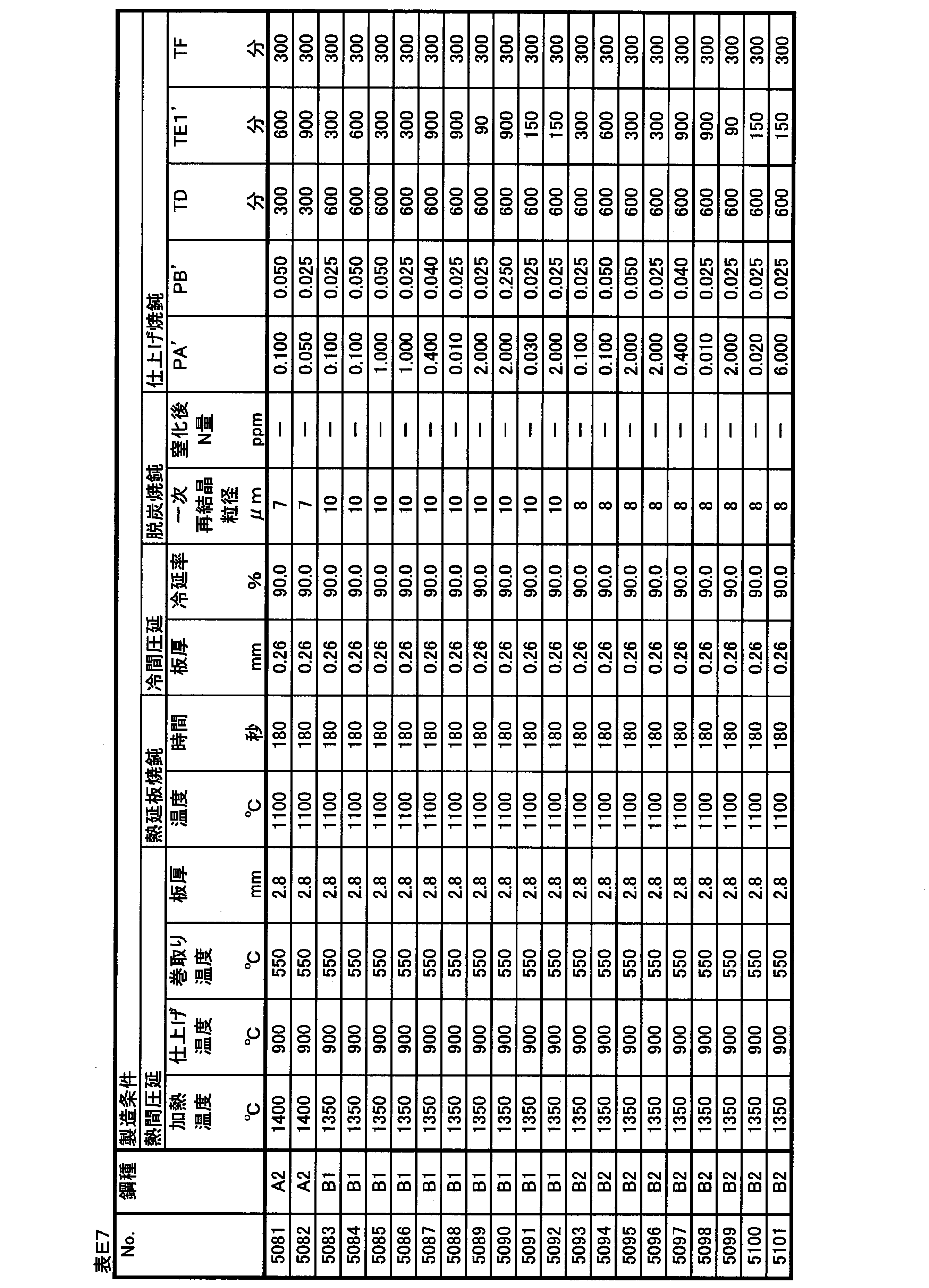
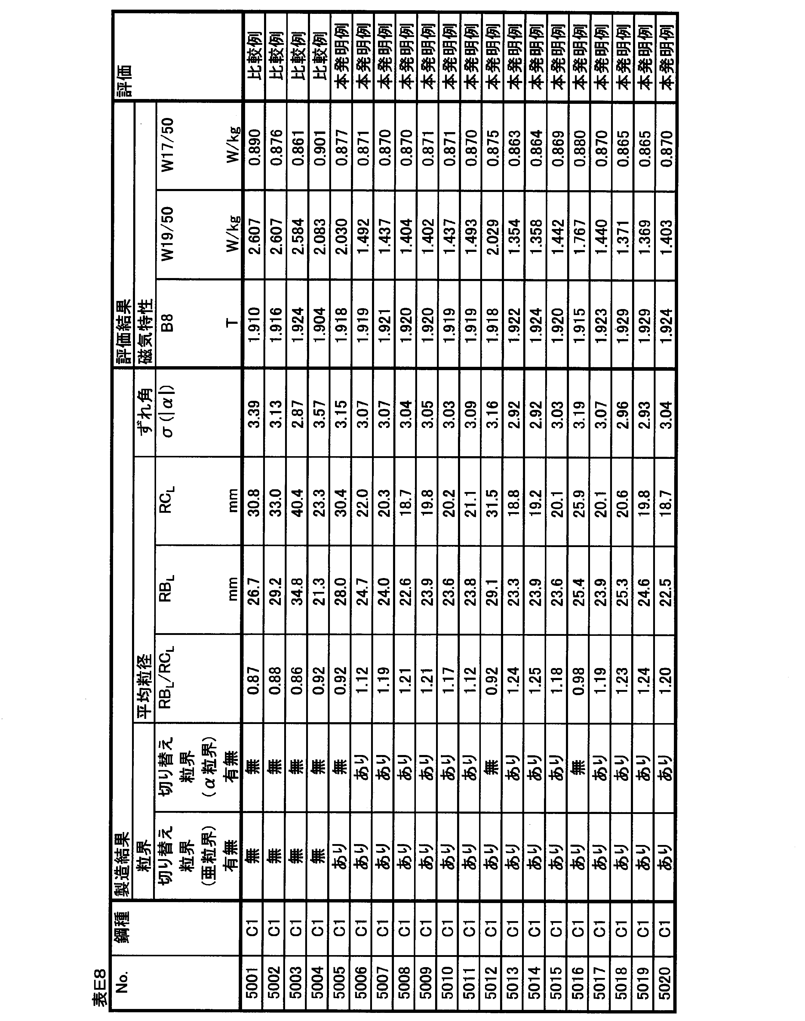
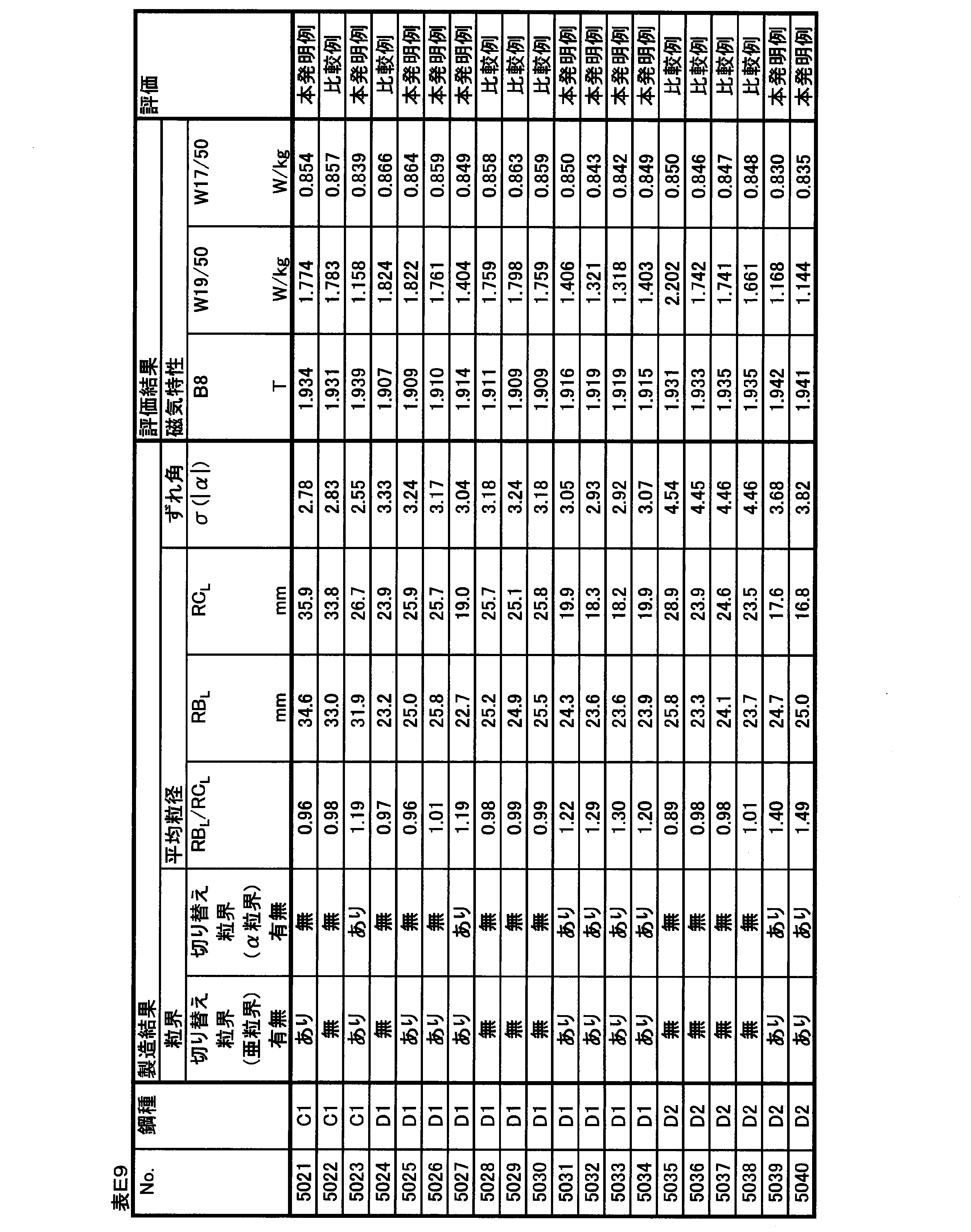


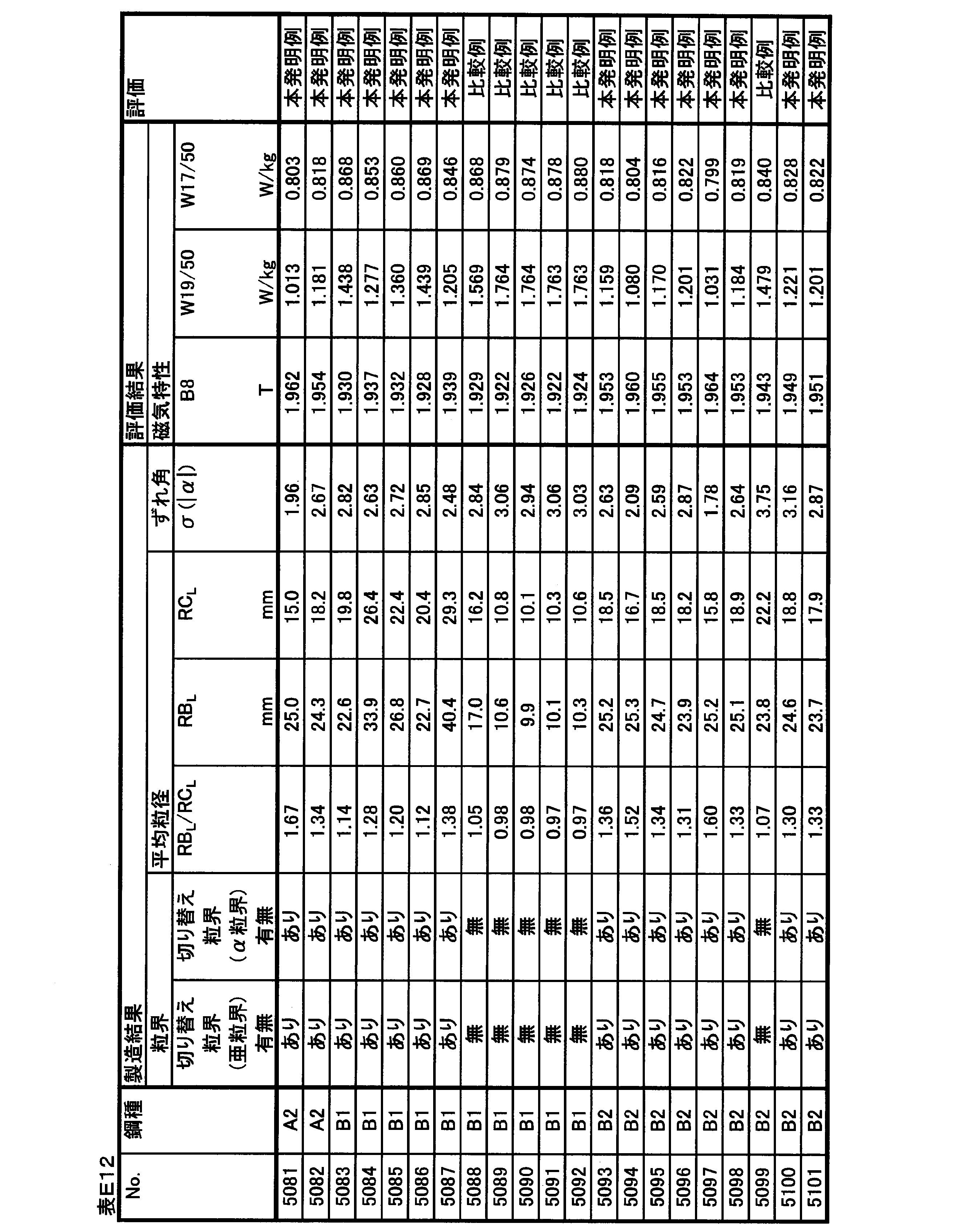
No.5001~5064は、スラブ加熱温度を低くして一次再結晶後の窒化によって二次再結晶の主要なインヒビターを形成するプロセスで製造した実施例である。 (Example manufactured by low-temperature slab heating process)
No. Examples 5001 to 5064 are examples manufactured by a process of forming a main inhibitor of secondary recrystallization by nitriding after primary recrystallization by lowering the slab heating temperature.
No.5001~5023は、Nbを含有しない鋼種を用いて、仕上げ焼鈍時に主にPA’、PB’、TD、およびTE1’の条件を変化させた実施例である。 (Examples of Nos. 5001 to 5023)
No. Examples 5001 to 5023 are examples in which the conditions of PA ′, PB ′, TD, and TE1 ′ are mainly changed at the time of finish annealing using a steel type not containing Nb.
No.5024~5034は、スラブ時点でNbを0.002%含有する鋼種を用いて、仕上げ焼鈍時に主にPA’、PB’、およびTE1’の条件を変化させた実施例である。 (Examples of Nos. 5024 to 5034)
No. Examples 5024 to 5034 are examples in which the conditions of PA ′, PB ′, and TE1 ′ are mainly changed at the time of finish annealing using a steel type containing 0.002% of Nb at the time of slab.
No.5035~5046は、スラブ時点でNbを0.007%含有する鋼種を用いた実施例である。 (Examples of Nos. 5035 to 5046)
No. Examples 5035 to 5046 are examples using steel types containing 0.007% of Nb at the time of slab.
No.5047~5054は、TE1’を300分未満の短時間とし、特にNb含有量の影響を確認した実施例である。 (Examples of Nos. 5047 to 5054)
No. 5047 to 5054 are examples in which TE1 ′ was set to a short time of less than 300 minutes and the influence of the Nb content was particularly confirmed.
No.5055~5064は、TE1’を300分未満の短時間とし、Nb群元素の含有量の影響を確認した実施例である。 (Examples of Nos. 5055 to 5064)
No. 5055 to 5064 are examples in which TE1 ′ was set to a short time of less than 300 minutes and the effect of the content of the Nb group element was confirmed.
No.5065~5101は、スラブ加熱温度を高くしてスラブ加熱中に十分に溶解したMnSを後工程で再析出させて主要なインヒビターとして活用するプロセスで製造した実施例である。 (Example manufactured by high-temperature slab heating process)
No. Examples 5065 to 5101 are examples manufactured by a process in which slab heating temperature is increased and MnS sufficiently dissolved during slab heating is reprecipitated in a later step and used as a main inhibitor.
表F1に示す化学組成を有するスラブを素材として、表F2に示す化学組成を有する方向性電磁鋼板を製造した。なお、化学組成の測定方法や、表中での記述方法は上記の実施例1と同じである。 (Example 6)
Grain-oriented electrical steel sheets having the chemical composition shown in Table F2 were produced from slabs having the chemical composition shown in Table F1. The method of measuring the chemical composition and the method of description in the table are the same as those in Example 1 described above.
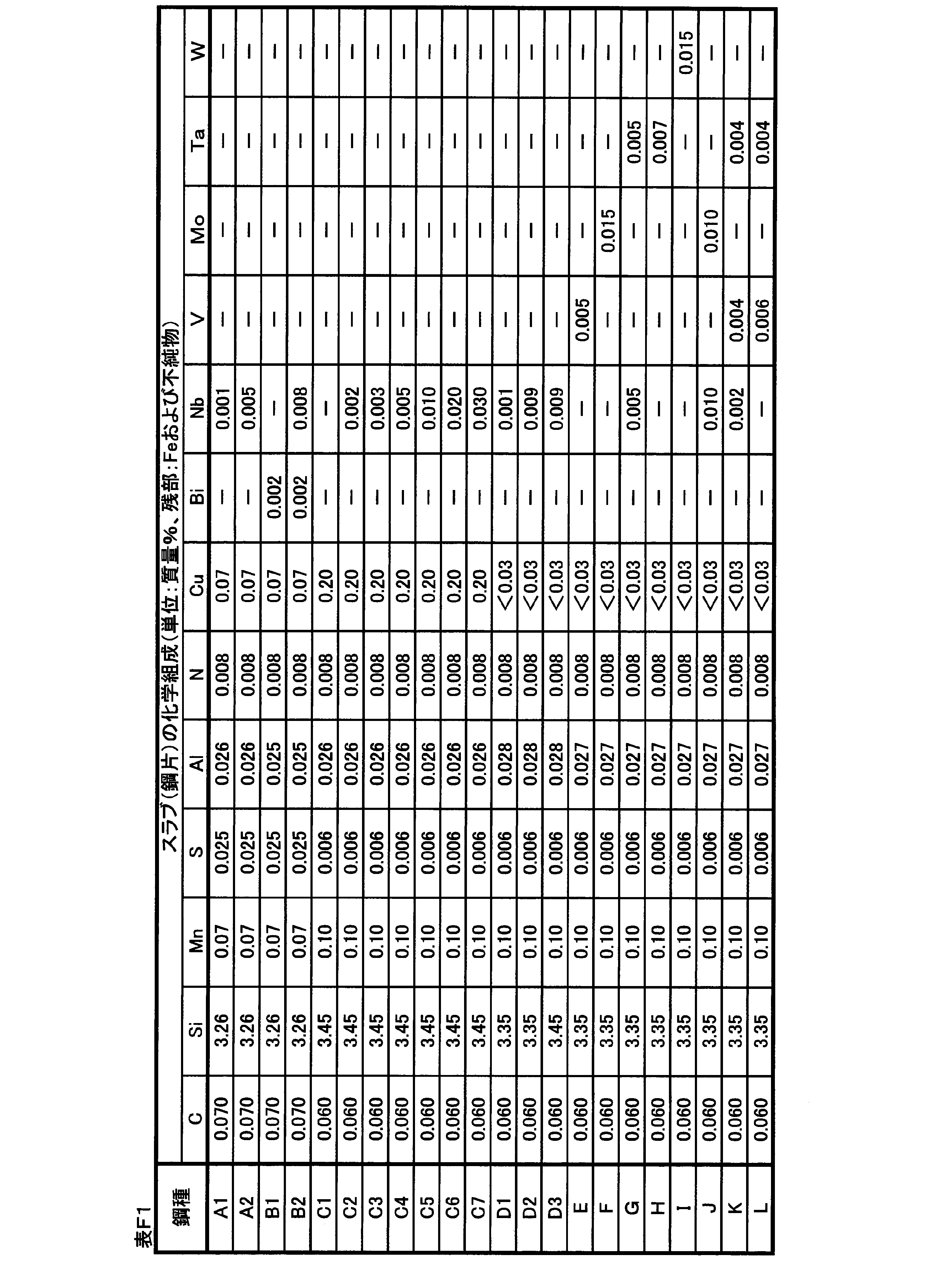

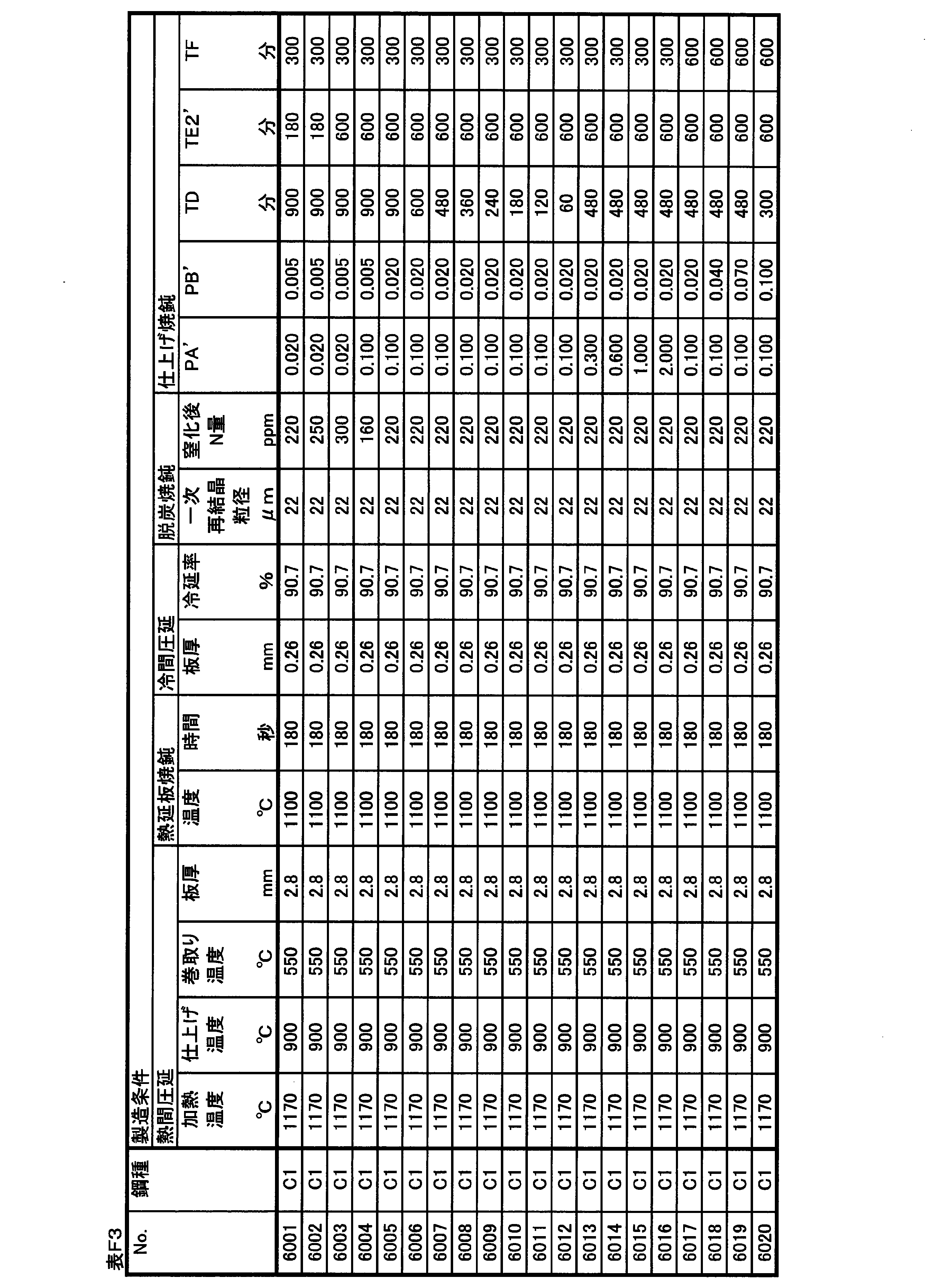

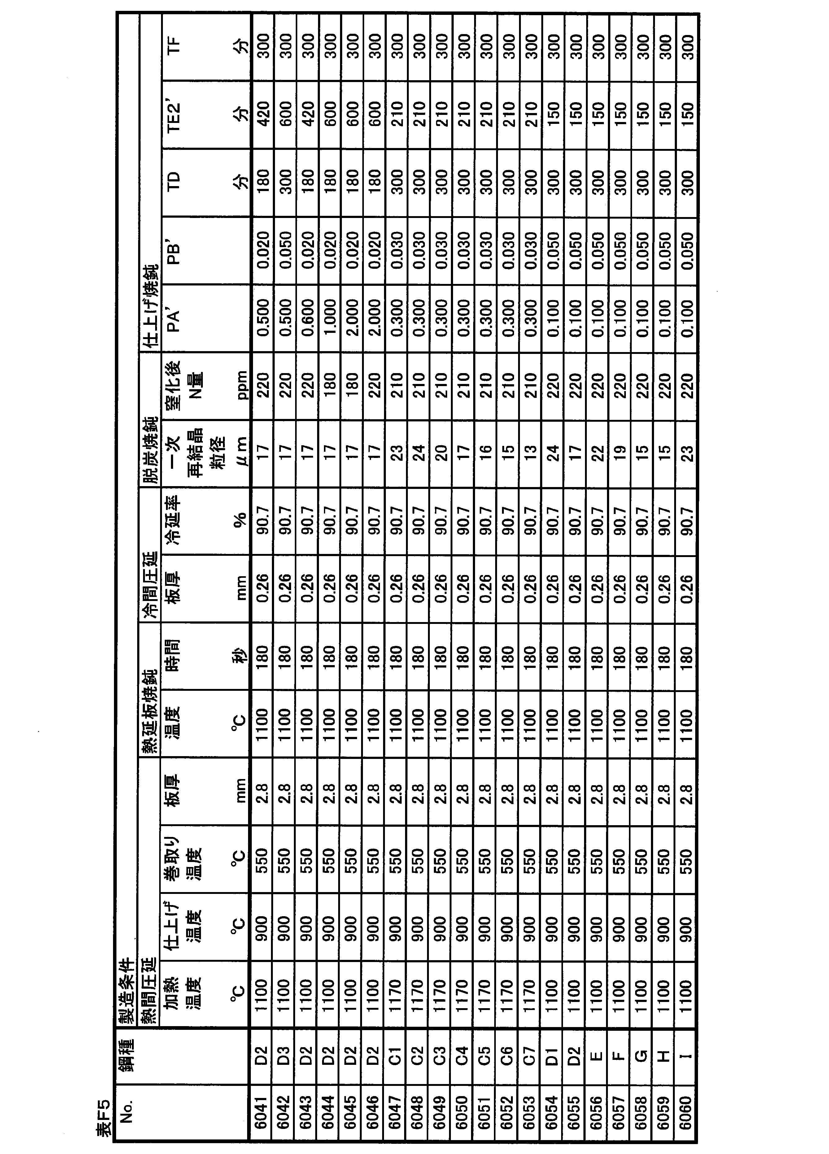
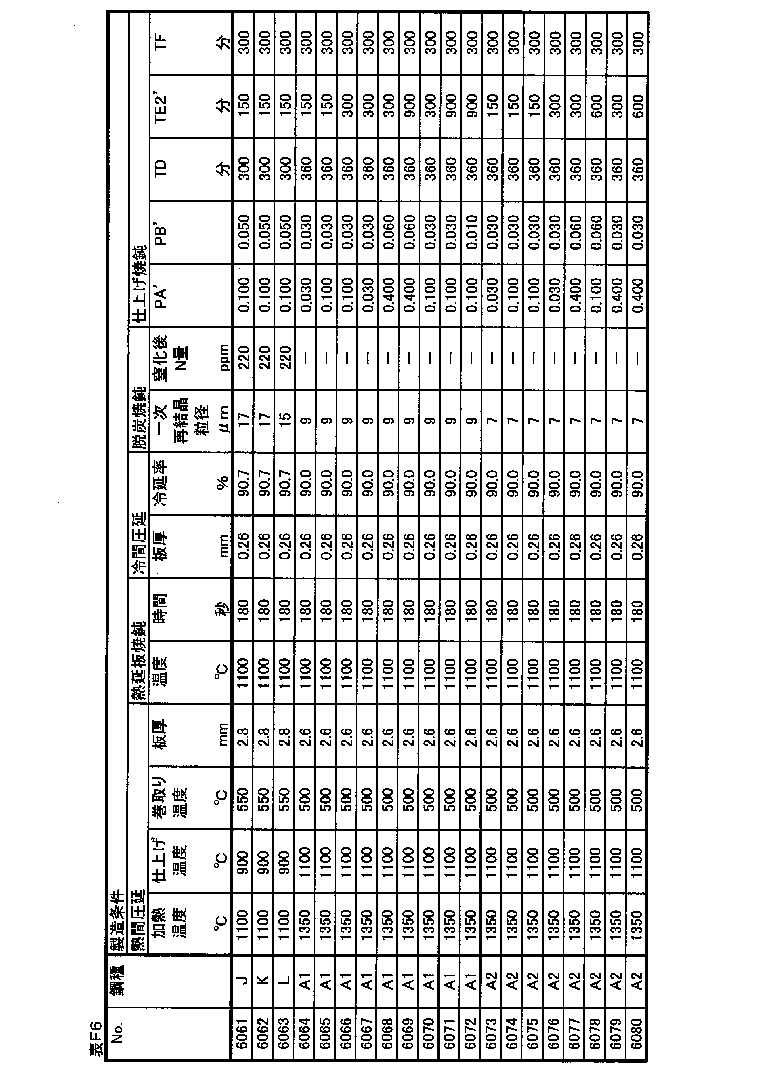

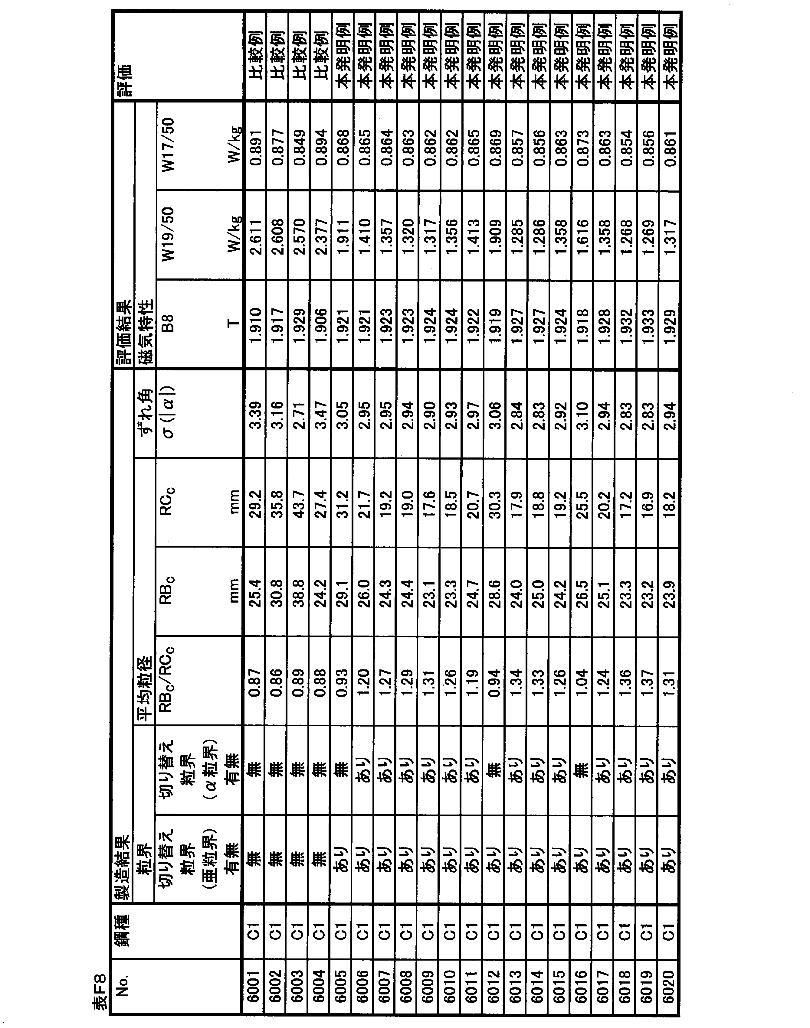

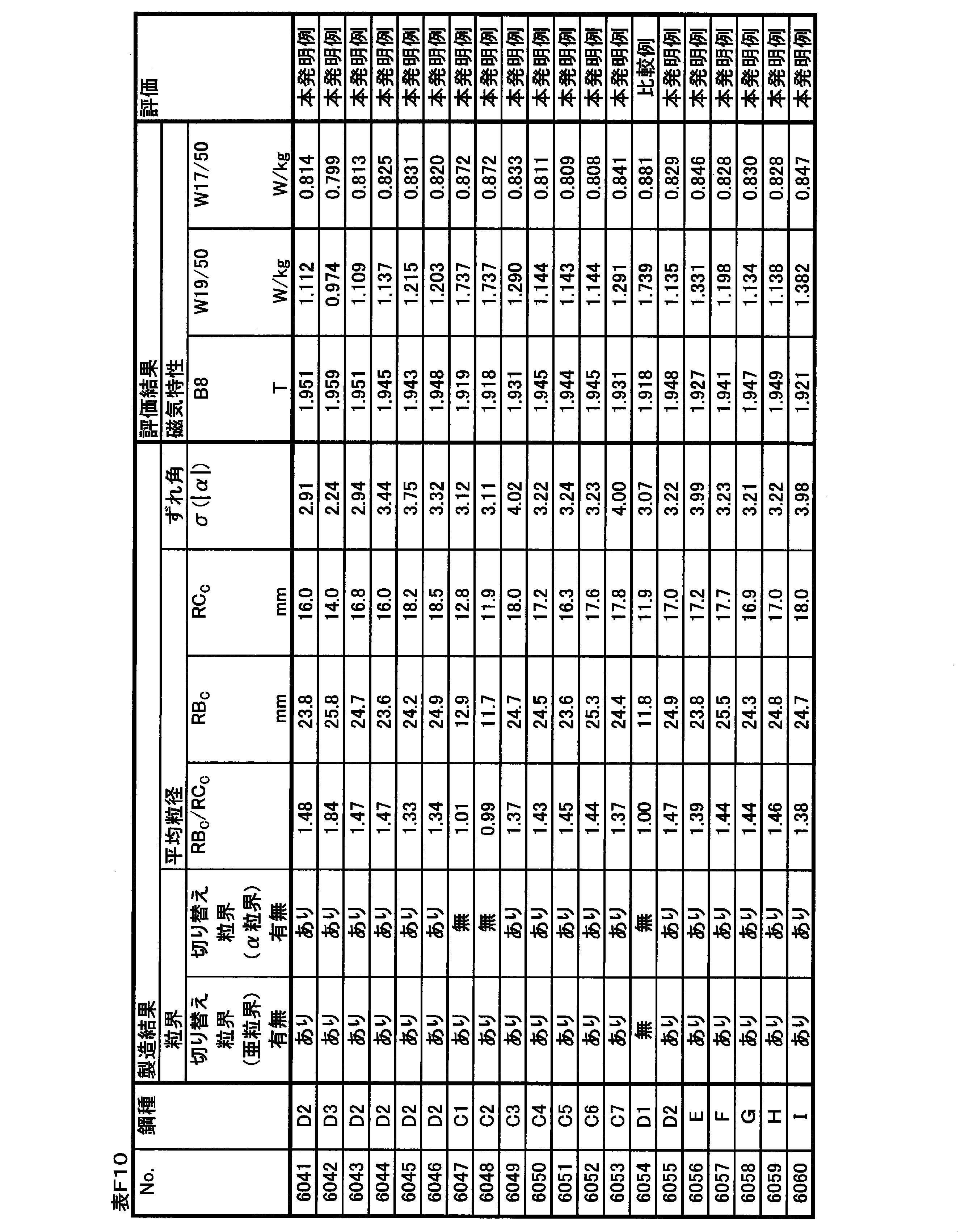
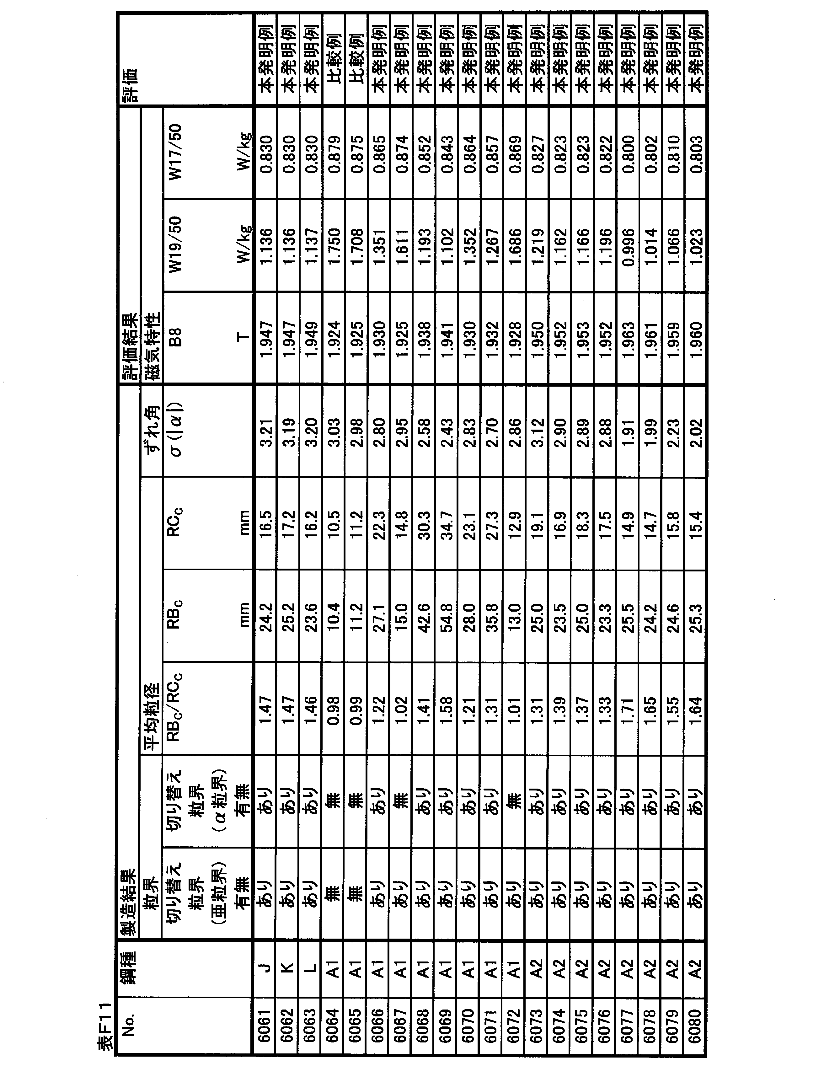

No.6001~6063は、スラブ加熱温度を低くして一次再結晶後の窒化によって二次再結晶の主要なインヒビターを形成するプロセスで製造した実施例である。 (Example manufactured by low-temperature slab heating process)
No. Examples 6001 to 6063 are examples manufactured by a process of forming a main inhibitor of secondary recrystallization by nitriding after primary recrystallization by lowering the slab heating temperature.
No.6001~6023は、Nbを含有しない鋼種を用いて、仕上げ焼鈍時に主にPA’、PB’、TD、およびTE2’の条件を変化させた実施例である。 (Examples of Nos. 6001 to 6023)
No. Examples 6001 to 6023 are examples in which the conditions of PA ′, PB ′, TD, and TE2 ′ are mainly changed at the time of finish annealing using a steel type not containing Nb.
No.6024~6034は、スラブ時点でNbを0.001%含有する鋼種を用いて、仕上げ焼鈍時に主にPA’、PB’、およびTE2’の条件を変化させた実施例である。 (Examples of Nos. 6024 to 6034)
No. Examples 6024 to 6034 are examples in which the condition of PA ′, PB ′, and TE2 ′ is mainly changed at the time of finish annealing using a steel type containing 0.001% of Nb at the time of slab.
No.6035~6046は、スラブ時点でNbを0.009%含有する鋼種を用いた実施例である。 (Examples of Nos. 6035 to 6046)
No. Nos. 6035 to 6046 are examples using steel types containing 0.009% of Nb at the time of slab.
No.6047~6053は、TE2’を300分未満の短時間とし、特にNb含有量の影響を確認した実施例である。 (Examples of Nos. 6047 to 6053)
No. Examples 6047 to 6053 are Examples in which TE2 ′ was set to a short time of less than 300 minutes and the influence of the Nb content was particularly confirmed.
No.6054~6063は、TE2’を300分未満の短時間とし、Nb群元素の含有量の影響を確認した実施例である。 (Examples of Nos. 6054 to 6063)
No. Examples 6054 to 6063 are examples in which the effect of the content of the Nb group element was confirmed by shortening the TE2 ′ to less than 300 minutes.
No.6064~6100は、スラブ加熱温度を高くしてスラブ加熱中に十分に溶解したMnSを後工程で再析出させて主要なインヒビターとして活用するプロセスで製造した実施例である。 (Example manufactured by high-temperature slab heating process)
No. Nos. 6064 to 6100 are examples produced by a process in which the slab heating temperature is increased and MnS sufficiently dissolved during slab heating is reprecipitated in a later step and used as a main inhibitor.
表G1に示す化学組成を有するスラブを素材として、表G2に示す化学組成を有する方向性電磁鋼板を製造とした。なお、化学組成の測定方法や、表中での記述方法は上記の実施例1と同じである。 (Example 7)
Using a slab having the chemical composition shown in Table G1 as a raw material, a grain-oriented electrical steel sheet having the chemical composition shown in Table G2 was produced. The method of measuring the chemical composition and the method of description in the table are the same as those in Example 1 described above.
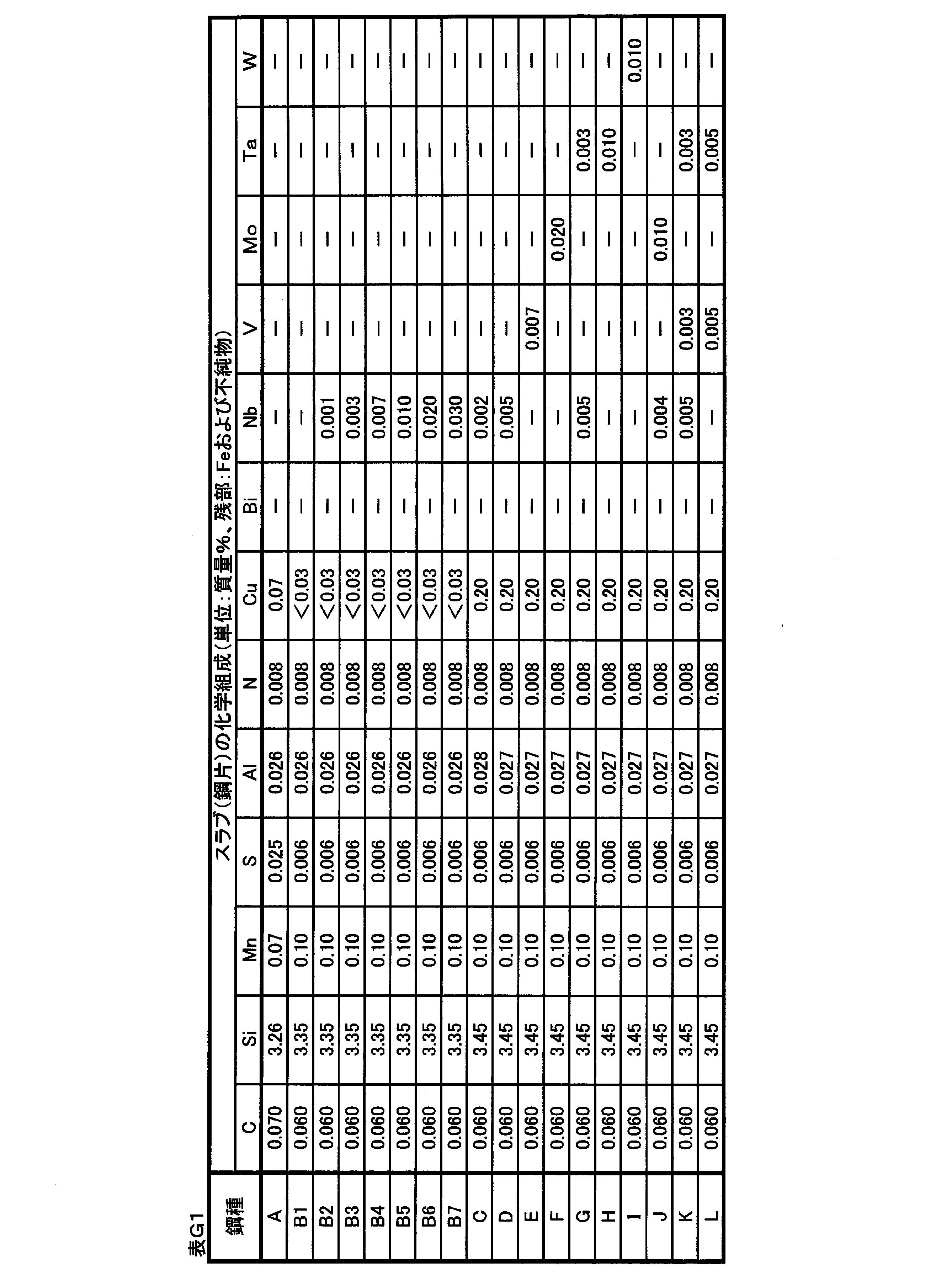
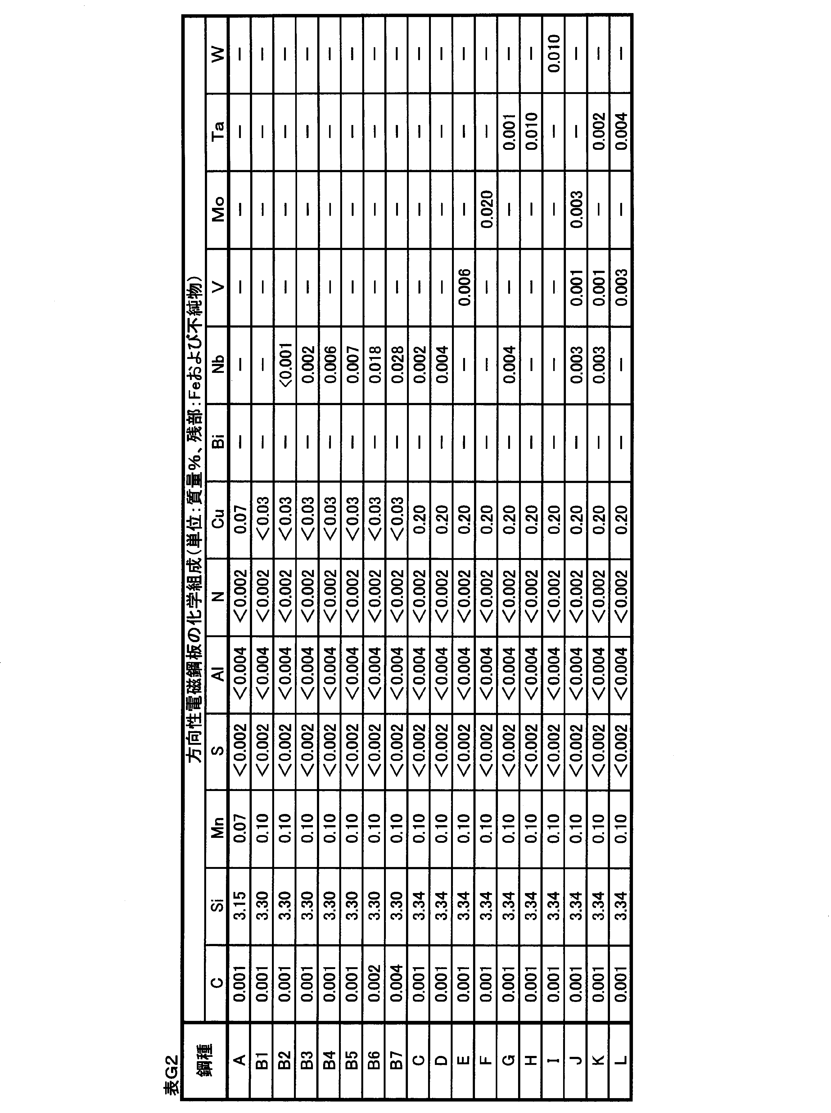
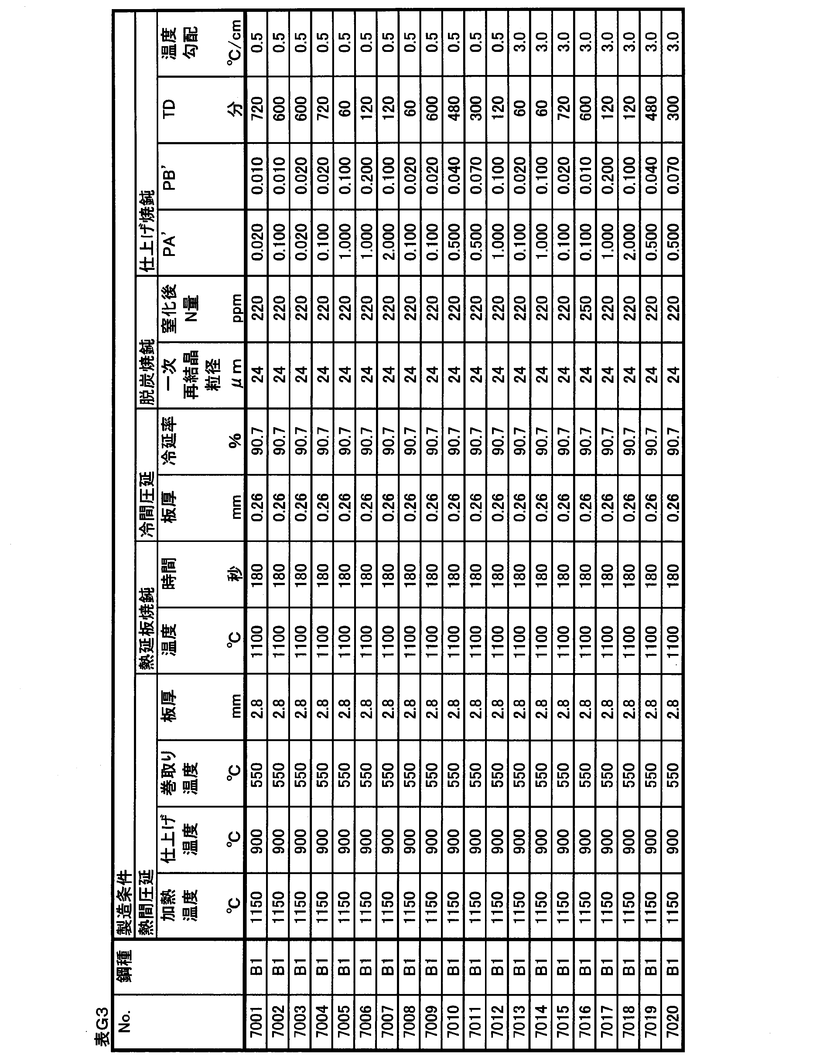

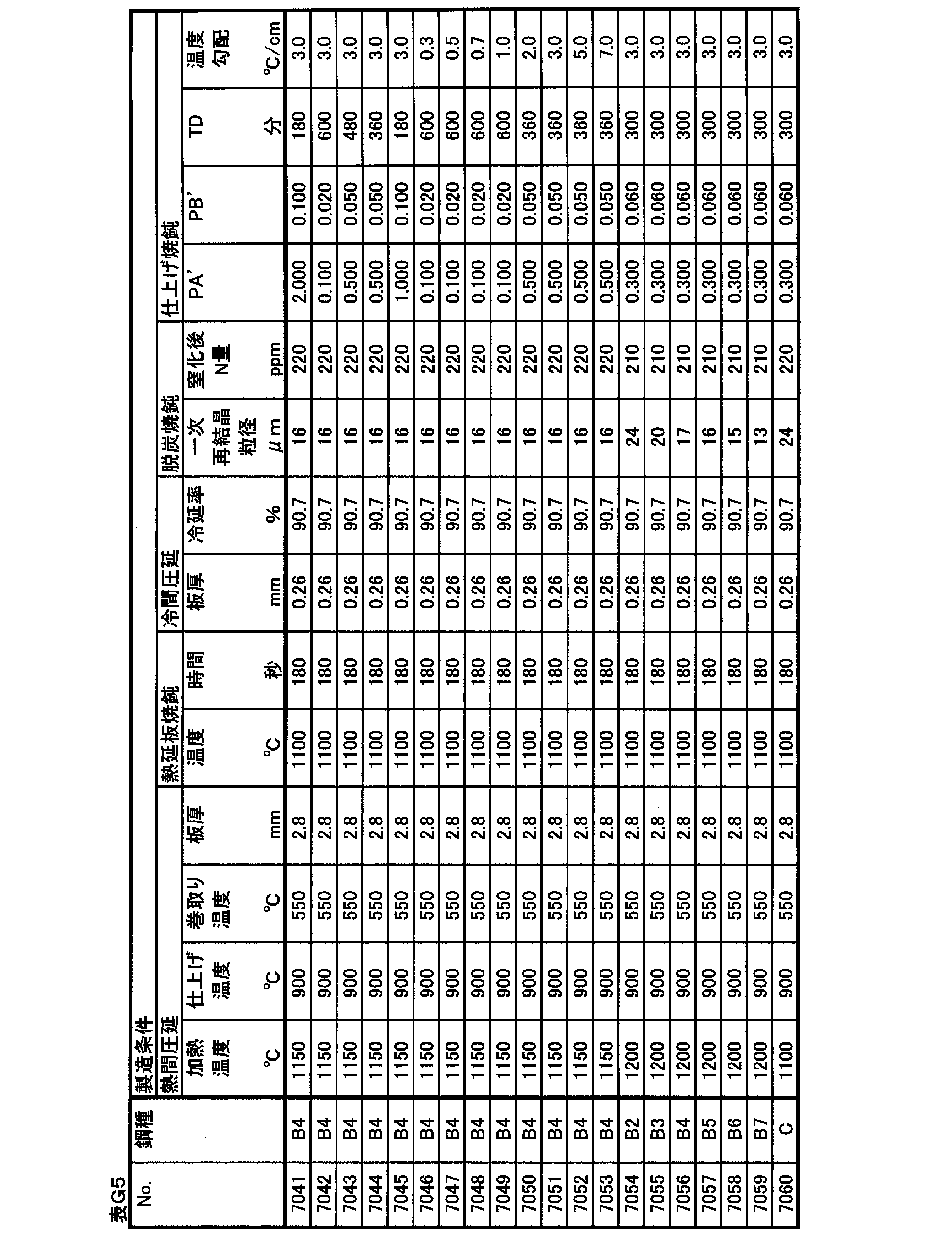
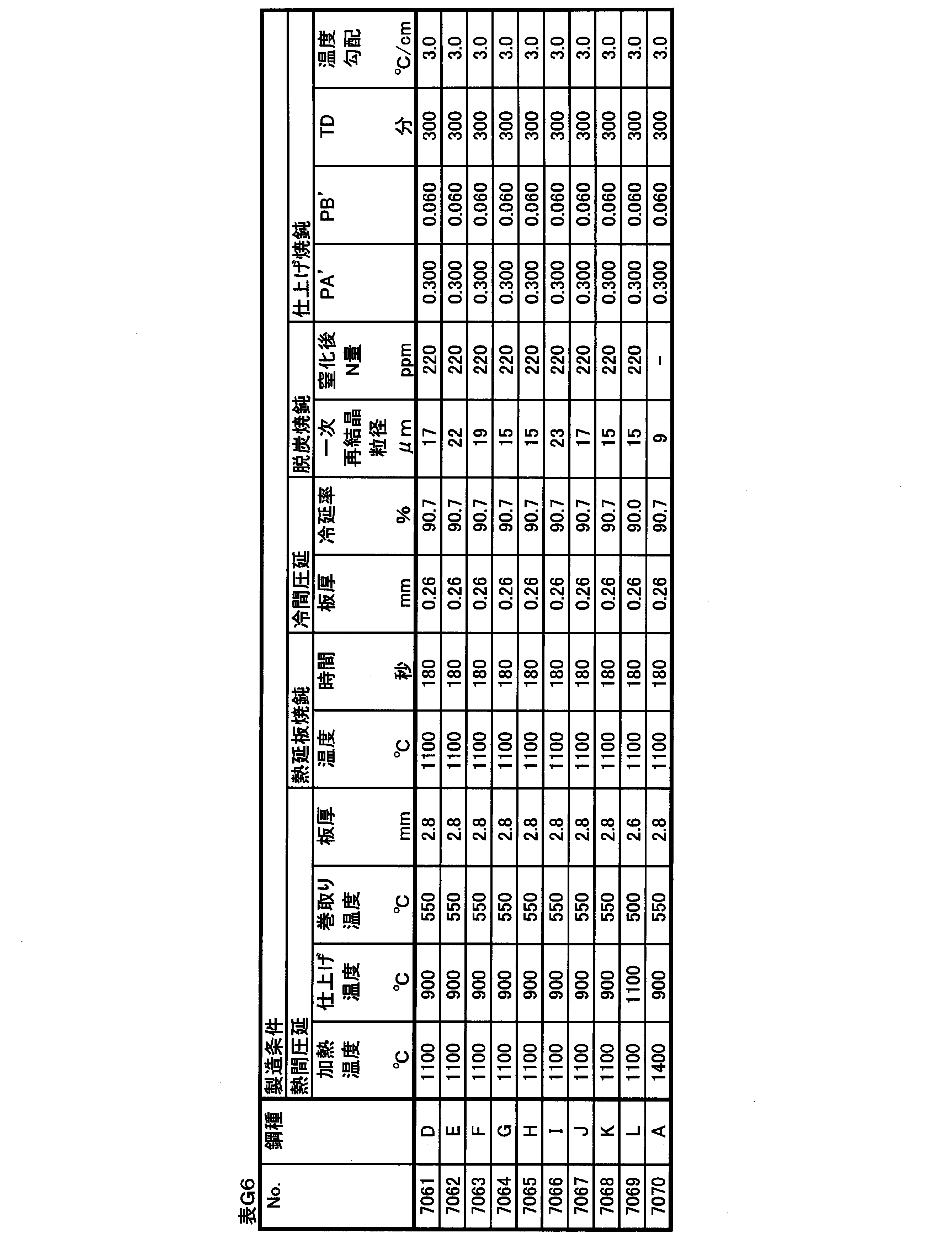

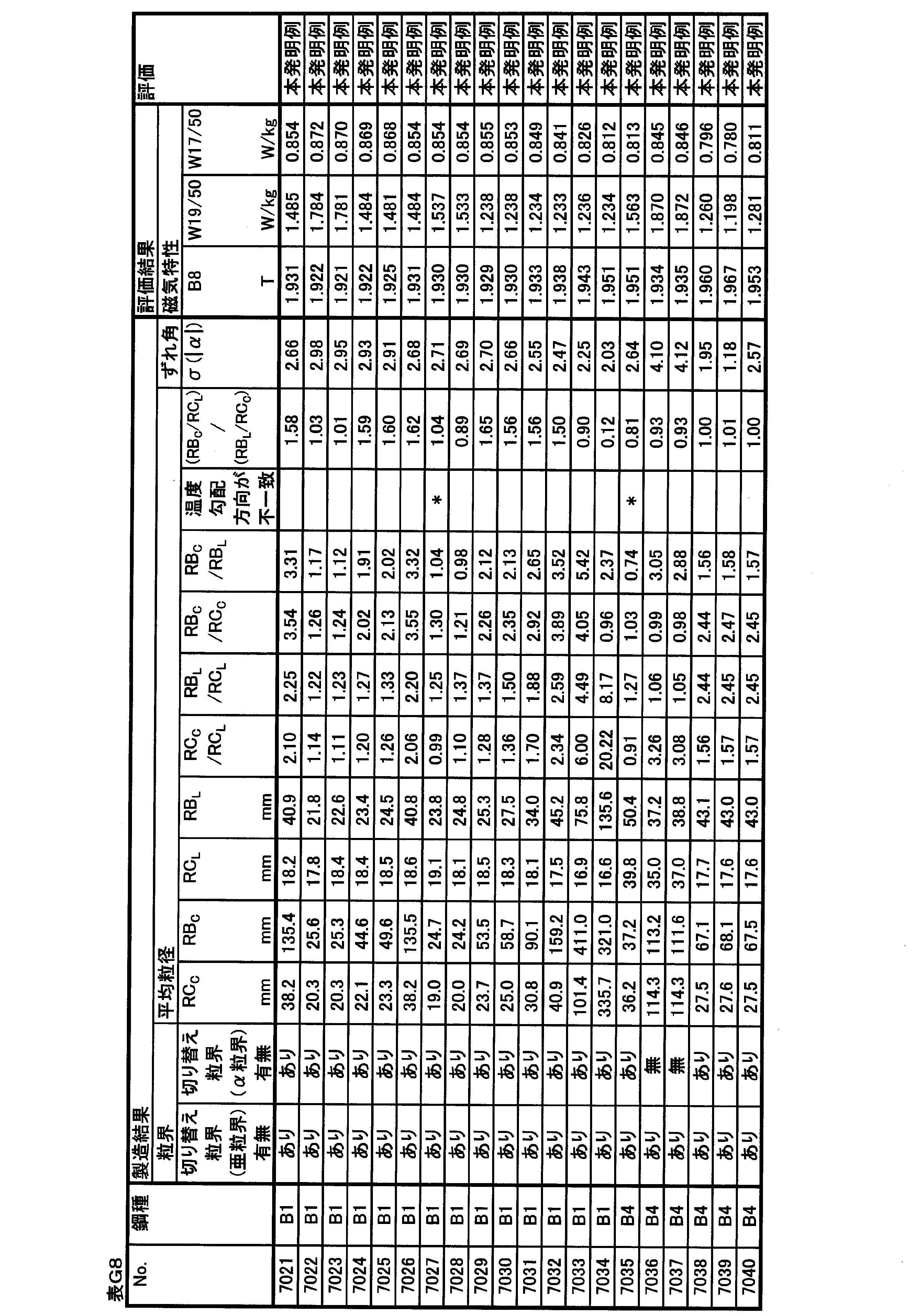
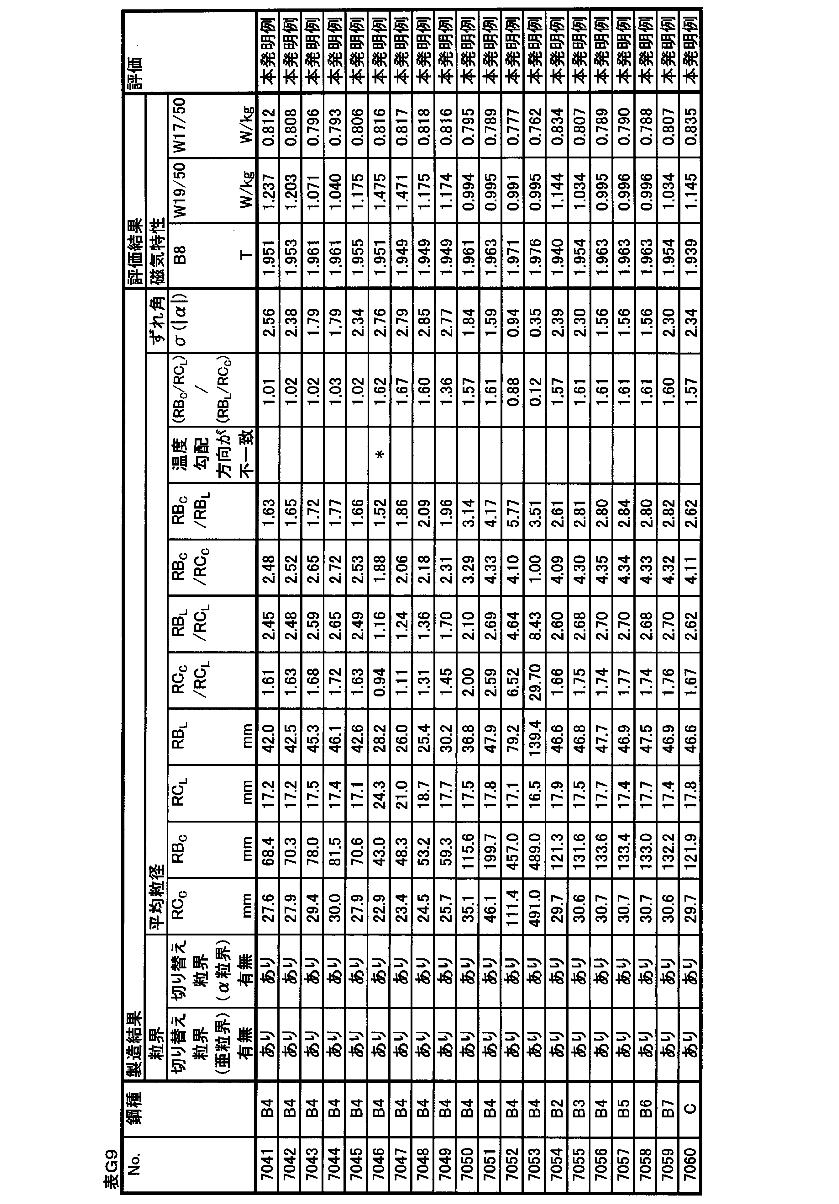

No.7001~7069は、スラブ加熱温度を低くして一次再結晶後の窒化によって二次再結晶の主要なインヒビターを形成するプロセスで製造した実施例である。 (Example manufactured by low-temperature slab heating process)
No. Examples 7001 to 7069 are examples manufactured by a process of forming a main inhibitor of secondary recrystallization by nitriding after primary recrystallization by lowering the slab heating temperature.
No.7001~7034は、Nbを含有しない鋼種を用いて、仕上げ焼鈍時に主にPA’、PB’、TD、および温度勾配の条件を変化させた実施例である。 (Examples of Nos. 7001 to 7034)
No. Examples 7001 to 7034 are examples in which the conditions of PA ′, PB ′, TD, and the temperature gradient are mainly changed at the time of finish annealing using a steel type not containing Nb.
No.7035~7069は、スラブ時点でNb群元素を含有する鋼種を用いて、仕上げ焼鈍時に主にPA’、PB’、TD、および温度勾配の条件を変化させた実施例である。 (Examples of Nos. 7035 to 7069)
No. Examples 7035 to 7069 are examples in which the conditions of PA ′, PB ′, TD, and the temperature gradient were mainly changed at the time of finish annealing using a steel type containing an Nb group element at the time of slab.
No.7070は、スラブ加熱温度を高くしてスラブ加熱中に十分に溶解したMnSを後工程で再析出させて主要なインヒビターとして活用するプロセスで製造した実施例である。 (Example of No. 7070)
No. 7070 is an embodiment manufactured by a process in which the slab heating temperature is raised and MnS sufficiently dissolved during slab heating is reprecipitated in a later step and used as a main inhibitor.
表H1に示す化学組成を有するスラブを素材として、表H2に示す化学組成を有する方向性電磁鋼板を製造した。なお、化学組成の測定方法や、表中での記述方法は上記の実施例1と同じである。 (Example 8)
Grain-oriented electrical steel sheets having the chemical composition shown in Table H2 were manufactured using slabs having the chemical composition shown in Table H1 as raw materials. The method of measuring the chemical composition and the method of description in the table are the same as those in Example 1 described above.

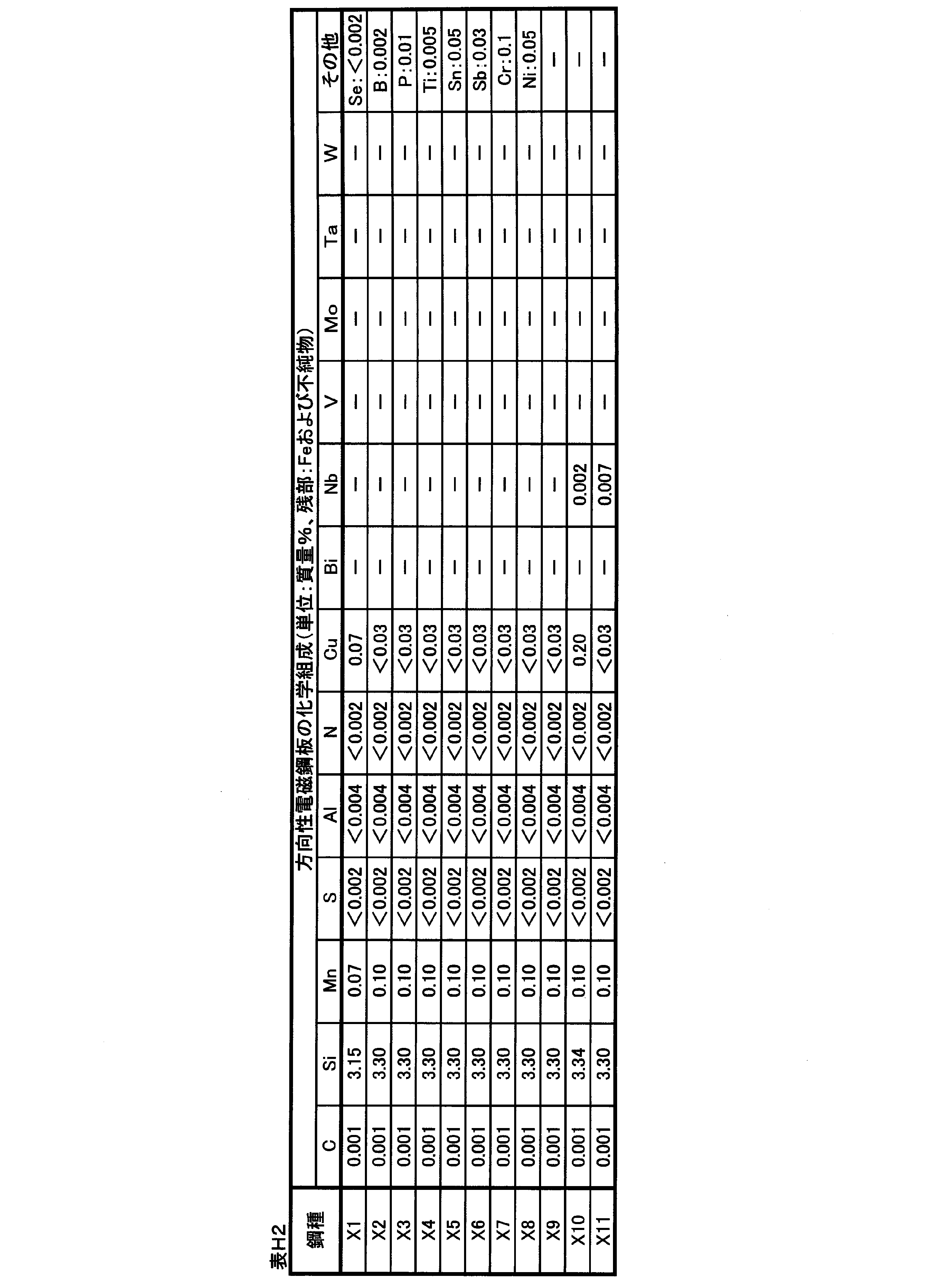
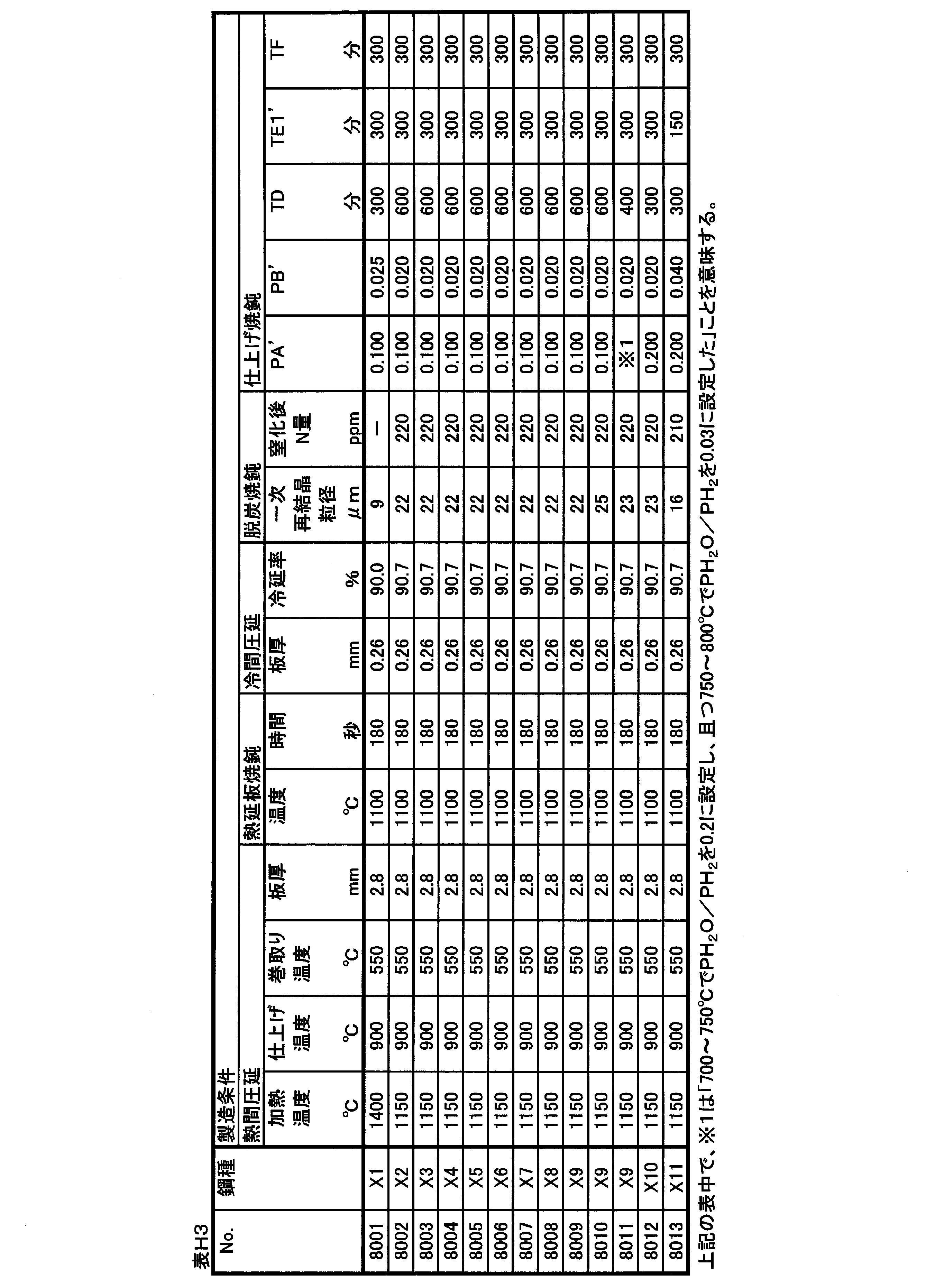
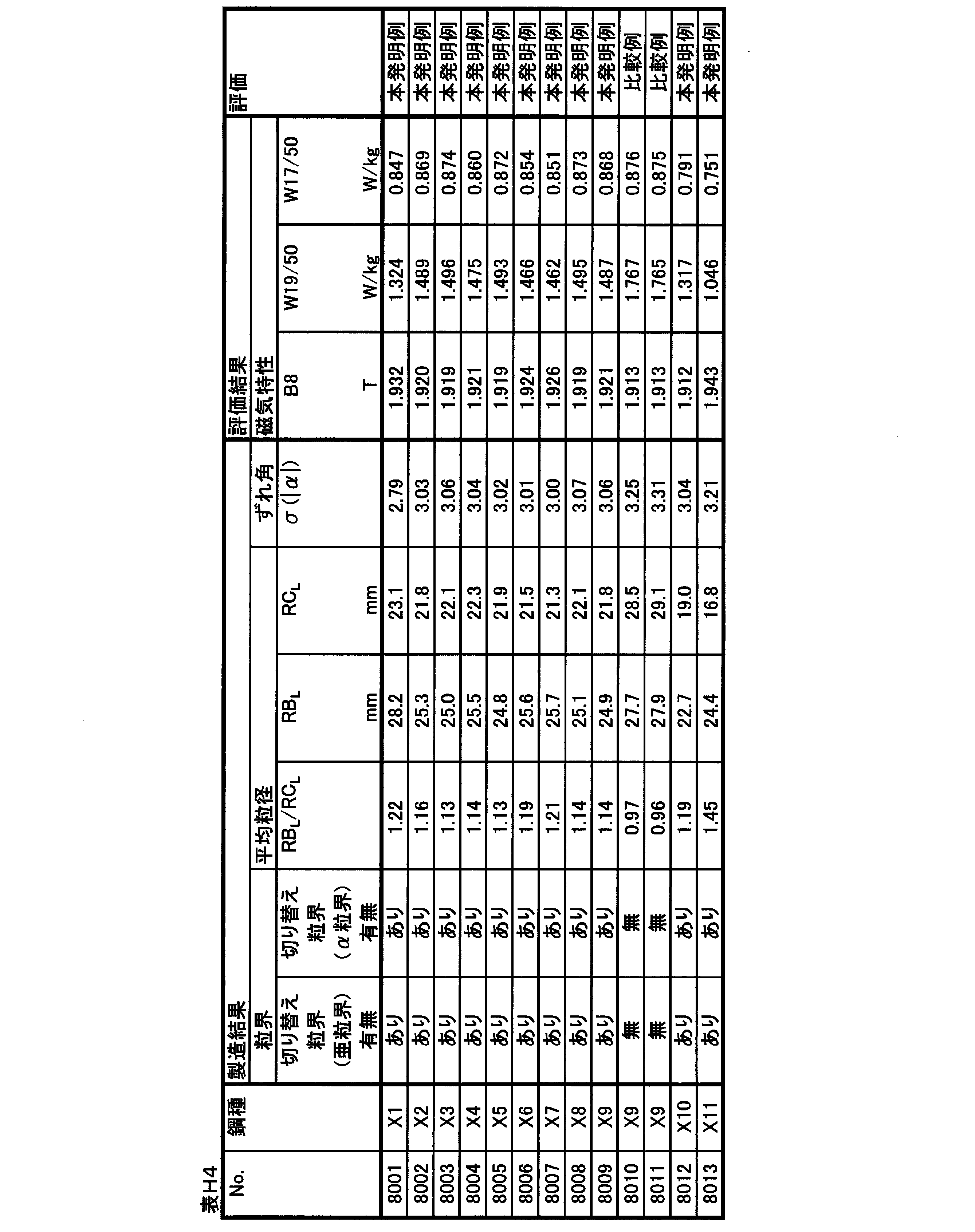
20 中間層
30 絶縁被膜 10 Oriented electrical steel sheet (silicon steel sheet)
20
Claims (18)
- 質量%で、
Si:2.0~7.0%、
Nb:0~0.030%、
V:0~0.030%、
Mo:0~0.030%、
Ta:0~0.030%、
W:0~0.030%、
C:0~0.0050%、
Mn:0~1.0%、
S:0~0.0150%、
Se:0~0.0150%、
Al:0~0.0650%、
N:0~0.0050%、
Cu:0~0.40%、
Bi:0~0.010%、
B:0~0.080%、
P:0~0.50%、
Ti:0~0.0150%、
Sn:0~0.10%、
Sb:0~0.10%、
Cr:0~0.30%、
Ni:0~1.0%、
を含有し、残部がFeおよび不純物からなる化学組成を有し、
Goss方位に配向する集合組織を有する方向性電磁鋼板において、
圧延面法線方向Zを回転軸とする理想Goss方位からのずれ角をαと定義し、
圧延直角方向Cを回転軸とする理想Goss方位からのずれ角をβと定義し、
圧延方向Lを回転軸とする理想Goss方位からのずれ角をγと定義し、
板面上で隣接し且つ間隔が1mmである2つの測定点で測定する結晶方位のずれ角を(α1 β1 γ1)および(α2 β2 γ2)と表し、
境界条件BAを[(α2-α1)2+(β2-β1)2+(γ2-γ1)2]1/2≧0.5°と定義し、
境界条件BBを[(α2-α1)2+(β2-β1)2+(γ2-γ1)2]1/2≧2.0°と定義するとき、
前記境界条件BAを満足し且つ前記境界条件BBを満足しない粒界が存在する、
ことを特徴とする方向性電磁鋼板。 In mass%,
Si: 2.0-7.0%,
Nb: 0 to 0.030%,
V: 0 to 0.030%,
Mo: 0 to 0.030%,
Ta: 0 to 0.030%,
W: 0 to 0.030%,
C: 0 to 0.0050%,
Mn: 0 to 1.0%,
S: 0 to 0.0150%,
Se: 0 to 0.0150%,
Al: 0 to 0.0650%,
N: 0 to 0.0050%,
Cu: 0 to 0.40%,
Bi: 0 to 0.010%,
B: 0 to 0.080%,
P: 0 to 0.50%,
Ti: 0 to 0.0150%,
Sn: 0 to 0.10%,
Sb: 0 to 0.10%,
Cr: 0 to 0.30%,
Ni: 0 to 1.0%,
And the balance has a chemical composition consisting of Fe and impurities,
In a grain-oriented electrical steel sheet having a texture oriented in the Goss orientation,
The deviation angle from the ideal Goss azimuth having the rolling surface normal direction Z as the rotation axis is defined as α,
The angle of deviation from the ideal Goss azimuth having the rotation perpendicular to the rolling perpendicular direction C is defined as β,
The shift angle from the ideal Goss direction with the rolling direction L as the rotation axis is defined as γ,
The deviation angles of the crystal orientations measured at two measurement points adjacent to each other on the plate surface and having an interval of 1 mm are represented by (α 1 β 1 γ 1 ) and (α 2 β 2 γ 2 ),
The boundary condition BA is defined as [(α 2 −α 1 ) 2 + (β 2 −β 1 ) 2 + (γ 2 −γ 1 ) 2 ] 1/2 ≧ 0.5 °,
When the boundary condition BB is defined as [(α 2 −α 1 ) 2 + (β 2 −β 1 ) 2 + (γ 2 −γ 1 ) 2 ] 1/2 ≧ 2.0 °,
There is a grain boundary that satisfies the boundary condition BA and does not satisfy the boundary condition BB.
A grain-oriented electrical steel sheet, characterized in that: - 前記境界条件BAに基づいて求める前記圧延方向Lの平均結晶粒径を粒径RALと定義し、
前記境界条件BBに基づいて求める前記圧延方向Lの平均結晶粒径を粒径RBLと定義するとき、
前記粒径RALと前記粒径RBLとが、1.15≦RBL÷RALを満たす、
ことを特徴とする請求項1に記載の方向性電磁鋼板。 The average crystal grain size in the rolling direction L obtained based on the boundary conditions BA defined as the particle size RA L,
When the average crystal grain size in the rolling direction L is defined as the particle diameter RB L obtained based on the boundary conditions BB,
And the particle size RA L and the diameter RB L satisfies the 1.15 ≦ RB L ÷ RA L,
The grain-oriented electrical steel sheet according to claim 1, wherein: - 前記境界条件BAに基づいて求める前記圧延直角方向Cの平均結晶粒径を粒径RACと定義し、
前記境界条件BBに基づいて求める前記圧延直角方向Cの平均結晶粒径を粒径RBCと定義するとき、
前記粒径RACと前記粒径RBCとが、1.15≦RBC÷RACを満たす、
ことを特徴とする請求項1または請求項2に記載の方向性電磁鋼板。 Wherein the average crystal grain size of the perpendicular to the rolling direction C is defined as the particle size RA C obtained based on the boundary conditions BA,
When the average crystal grain size of the perpendicular to the rolling direction C is defined as the particle diameter RB C obtained based on the boundary conditions BB,
And the particle size RA C and the particle diameter RB C satisfies the 1.15 ≦ RB C ÷ RA C,
The grain-oriented electrical steel sheet according to claim 1 or 2, characterized in that: - 前記境界条件BAに基づいて求める前記圧延方向Lの平均結晶粒径を粒径RALと定義し、
前記境界条件BAに基づいて求める前記圧延直角方向Cの平均結晶粒径を粒径RACと定義するとき、
前記粒径RALと前記粒径RACとが、1.15≦RAC÷RALを満たす、
ことを特徴とする請求項1~3の何れか一項に記載の方向性電磁鋼板。 The average crystal grain size in the rolling direction L obtained based on the boundary conditions BA defined as the particle size RA L,
When the average crystal grain size of the perpendicular to the rolling direction C is defined as the particle size RA C obtained based on the boundary conditions BA,
And the particle size RA L and the grain size RA C satisfies the 1.15 ≦ RA C ÷ RA L,
The grain-oriented electrical steel sheet according to any one of claims 1 to 3, characterized in that: - 前記境界条件BBに基づいて求める前記圧延方向Lの平均結晶粒径を粒径RBLと定義し、
前記境界条件BBに基づいて求める前記圧延直角方向Cの平均結晶粒径を粒径RBCと定義するとき、
前記粒径RBLと前記粒径RBCとが、1.50≦RBC÷RBLを満たす、
ことを特徴とする請求項1~4の何れか一項に記載の方向性電磁鋼板。 The average crystal grain size in the rolling direction L obtained based on the boundary conditions BB is defined as the particle diameter RB L,
When the average crystal grain size of the perpendicular to the rolling direction C is defined as the particle diameter RB C obtained based on the boundary conditions BB,
And the particle diameter RB L and the diameter RB C satisfies the 1.50 ≦ RB C ÷ RB L,
The grain-oriented electrical steel sheet according to any one of claims 1 to 4, characterized in that: - 前記境界条件BAに基づいて求める前記圧延方向Lの平均結晶粒径を粒径RALと定義し、
前記境界条件BBに基づいて求める前記圧延方向Lの平均結晶粒径を粒径RBLと定義し、
前記境界条件BAに基づいて求める前記圧延直角方向Cの平均結晶粒径を粒径RACと定義し、
前記境界条件BBに基づいて求める前記圧延直角方向Cの平均結晶粒径を粒径RBCと定義するとき、
前記粒径RALと前記粒径RACと前記粒径RBLと前記粒径RBCとが、
(RBC×RAL)÷(RBL×RAC)<1.0を満たす、
ことを特徴とする請求項1~5の何れか一項に記載の方向性電磁鋼板。 The average crystal grain size in the rolling direction L obtained based on the boundary conditions BA defined as the particle size RA L,
The average crystal grain size in the rolling direction L obtained based on the boundary conditions BB is defined as the particle diameter RB L,
Wherein the average crystal grain size of the perpendicular to the rolling direction C is defined as the particle size RA C obtained based on the boundary conditions BA,
When the average crystal grain size of the perpendicular to the rolling direction C is defined as the particle diameter RB C obtained based on the boundary conditions BB,
And the particle size RA L and the grain size RA C and the particle diameter RB L and the diameter RB C is,
Satisfy (RB C × RA L) ÷ (RB L × RA C) <1.0,
The grain-oriented electrical steel sheet according to any one of claims 1 to 5, characterized in that: - 板面上の測定点で測定する結晶方位のずれ角を(α β γ)と表し、各測定点でのずれ角をθ=[α2+β2+γ2]1/2と定義するとき、
前記ずれ角θの絶対値の標準偏差σ(θ)が、0°以上3.0°以下である、ことを特徴とする請求項1~6の何れか一項に記載の方向性電磁鋼板。 When the shift angle of the crystal orientation measured at the measurement point on the plate surface is expressed as (αβγ), and the shift angle at each measurement point is defined as θ = [α 2 + β 2 + γ 2 ] 1/2 ,
The grain-oriented electrical steel sheet according to any one of claims 1 to 6, wherein a standard deviation σ (θ) of an absolute value of the shift angle θ is 0 ° or more and 3.0 ° or less. - 境界条件BCを|α2-α1|≧0.5°と定義するとき、
前記境界条件BCを満足し且つ前記境界条件BBを満足しない粒界が存在する、ことを特徴とする請求項1~7の何れか一項に記載の方向性電磁鋼板。 When the boundary condition BC is defined as | α 2 −α 1 | ≧ 0.5 °,
The grain-oriented electrical steel sheet according to any one of claims 1 to 7, wherein a grain boundary that satisfies the boundary condition BC and does not satisfy the boundary condition BB exists. - 前記境界条件BCに基づいて求める前記圧延方向Lの平均結晶粒径を粒径RCLと定義し、
前記境界条件BBに基づいて求める前記圧延方向Lの平均結晶粒径を粒径RBLと定義するとき、
前記粒径RCLと前記粒径RBLとが、1.10≦RBL÷RCLを満たす、
ことを特徴とする請求項1~8の何れか一項に記載の方向性電磁鋼板。 The average crystal grain size in the rolling direction L determined based on the boundary condition BC is defined as a grain size RC L ,
When the average crystal grain size in the rolling direction L is defined as the particle diameter RB L obtained based on the boundary conditions BB,
And the particle size RC L and the diameter RB L satisfies the 1.10 ≦ RB L ÷ RC L,
The grain-oriented electrical steel sheet according to any one of claims 1 to 8, characterized in that: - 前記境界条件BCに基づいて求める前記圧延直角方向Cの平均結晶粒径を粒径RCCと定義し、
前記境界条件BBに基づいて求める前記圧延直角方向Cの平均結晶粒径を粒径RBCと定義するとき、
前記粒径RCCと前記粒径RBCとが、1.10≦RBC÷RCCを満たす、
ことを特徴とする請求項1~9の何れか一項に記載の方向性電磁鋼板。 Wherein the average crystal grain size of the perpendicular to the rolling direction C is defined as the particle size RC C obtained based on the boundary condition BC,
When the average crystal grain size of the perpendicular to the rolling direction C is defined as the particle diameter RB C obtained based on the boundary conditions BB,
And the particle size RC C and the particle diameter RB C satisfies the 1.10 ≦ RB C ÷ RC C,
The grain-oriented electrical steel sheet according to any one of claims 1 to 9, characterized in that: - 前記境界条件BCに基づいて求める前記圧延方向Lの平均結晶粒径を粒径RCLと定義し、
前記境界条件BCに基づいて求める前記圧延直角方向Cの平均結晶粒径を粒径RCCと定義するとき、
前記粒径RCLと前記粒径RCCとが、1.15≦RCC÷RCLを満たす、
ことを特徴とする請求項1~10の何れか一項に記載の方向性電磁鋼板。 The average crystal grain size in the rolling direction L determined based on the boundary condition BC is defined as a grain size RC L ,
When the average crystal grain size of the perpendicular to the rolling direction C is defined as the particle size RC C obtained based on the boundary condition BC,
The particle size RC L and the particle size RC C satisfy 1.15 ≦ RC C ÷ RC L ,
The grain-oriented electrical steel sheet according to any one of claims 1 to 10, characterized in that: - 前記境界条件BCに基づいて求める前記圧延方向Lの平均結晶粒径を粒径RCLと定義し、
前記境界条件BBに基づいて求める前記圧延方向Lの平均結晶粒径を粒径RBLと定義し、
前記境界条件BCに基づいて求める前記圧延直角方向Cの平均結晶粒径を粒径RCCと定義し、
前記境界条件BBに基づいて求める前記圧延直角方向Cの平均結晶粒径を粒径RBCと定義するとき、
前記粒径RCLと前記粒径RCCと前記粒径RBLと前記粒径RBCとが、
(RBC×RCL)÷(RBL×RCC)<1.0を満たす、
ことを特徴とする請求項1~11の何れか一項に記載の方向性電磁鋼板。 The average crystal grain size in the rolling direction L determined based on the boundary condition BC is defined as a grain size RC L ,
The average crystal grain size in the rolling direction L obtained based on the boundary conditions BB is defined as the particle diameter RB L,
Wherein the average crystal grain size of the perpendicular to the rolling direction C is defined as the particle size RC C obtained based on the boundary condition BC,
When the average crystal grain size of the perpendicular to the rolling direction C is defined as the particle diameter RB C obtained based on the boundary conditions BB,
And the particle size RC L and the grain size RC C and the particle diameter RB L and the diameter RB C is,
Satisfy (RB C × RC L) ÷ (RB L × RC C) <1.0,
The grain-oriented electrical steel sheet according to any one of claims 1 to 11, characterized in that: - 前記ずれ角αの絶対値の標準偏差σ(|α|)が、0°以上3.50°以下である、ことを特徴とする請求項1~12の何れか一項に記載の方向性電磁鋼板。 The directional electromagnetic device according to any one of claims 1 to 12, wherein a standard deviation σ (| α |) of an absolute value of the shift angle α is 0 ° or more and 3.50 ° or less. steel sheet.
- 前記化学組成として、Nb、V、Mo、Ta、およびWからなる群から選択される少なくとも1種を合計で0.0030~0.030質量%含有する、
ことを特徴とする請求項1~13の何れか一項に記載の方向性電磁鋼板。 As the chemical composition, at least one selected from the group consisting of Nb, V, Mo, Ta, and W is contained in a total amount of 0.0030 to 0.030% by mass.
The grain-oriented electrical steel sheet according to any one of claims 1 to 13, characterized in that: - 局所的な微小歪の付与または局所的な溝の形成の少なくとも1つによって磁区が細分化されている、ことを特徴とする請求項1~14の何れか一項に記載の方向性電磁鋼板。 The grain-oriented electrical steel sheet according to any one of claims 1 to 14, wherein the magnetic domains are subdivided by at least one of local microstrain application and local groove formation.
- 前記方向性電磁鋼板上に接して配された中間層と、前記中間層上に接して配された絶縁被膜とを有する、ことを特徴とする請求項1~15の何れか一項に記載の方向性電磁鋼板。 The method according to any one of claims 1 to 15, further comprising: an intermediate layer disposed in contact with the grain-oriented electrical steel sheet; and an insulating coating disposed in contact with the intermediate layer. Grain-oriented electrical steel sheets.
- 前記中間層が平均厚さ1~3μmのフォルステライト被膜である、ことを特徴とする請求項16に記載の方向性電磁鋼板。 17. The grain-oriented electrical steel sheet according to claim 16, wherein the intermediate layer is a forsterite film having an average thickness of 1 to 3 μm.
- 前記中間層が平均厚さ2~500nmの酸化膜である、ことを特徴とする請求項16に記載の方向性電磁鋼板。 17. The grain-oriented electrical steel sheet according to claim 16, wherein the intermediate layer is an oxide film having an average thickness of 2 to 500 nm.
Priority Applications (7)
| Application Number | Priority Date | Filing Date | Title |
|---|---|---|---|
| CN201980049675.6A CN112469840B (en) | 2018-07-31 | 2019-07-31 | Grain-oriented electromagnetic steel sheet |
| JP2020534713A JP7028325B2 (en) | 2018-07-31 | 2019-07-31 | Directional electrical steel sheet |
| RU2021101788A RU2764625C1 (en) | 2018-07-31 | 2019-07-31 | Anisotropic electrical steel sheet |
| EP19843927.5A EP3831974A4 (en) | 2018-07-31 | 2019-07-31 | Grain-oriented electromagnetic steel sheet |
| KR1020217002559A KR102457420B1 (en) | 2018-07-31 | 2019-07-31 | grain-oriented electrical steel sheet |
| BR112021000803-9A BR112021000803A2 (en) | 2018-07-31 | 2019-07-31 | GRAIN ORIENTED ELECTRIC STEEL SHEET |
| US17/263,824 US11939641B2 (en) | 2018-07-31 | 2019-07-31 | Grain oriented electrical steel sheet |
Applications Claiming Priority (12)
| Application Number | Priority Date | Filing Date | Title |
|---|---|---|---|
| JP2018143904 | 2018-07-31 | ||
| JP2018-143905 | 2018-07-31 | ||
| JP2018-143902 | 2018-07-31 | ||
| JP2018-143898 | 2018-07-31 | ||
| JP2018-143900 | 2018-07-31 | ||
| JP2018-143904 | 2018-07-31 | ||
| JP2018-143901 | 2018-07-31 | ||
| JP2018143901 | 2018-07-31 | ||
| JP2018143905 | 2018-07-31 | ||
| JP2018143900 | 2018-07-31 | ||
| JP2018143902 | 2018-07-31 | ||
| JP2018143898 | 2018-07-31 |
Publications (1)
| Publication Number | Publication Date |
|---|---|
| WO2020027215A1 true WO2020027215A1 (en) | 2020-02-06 |
Family
ID=69231800
Family Applications (1)
| Application Number | Title | Priority Date | Filing Date |
|---|---|---|---|
| PCT/JP2019/030059 WO2020027215A1 (en) | 2018-07-31 | 2019-07-31 | Grain-oriented electromagnetic steel sheet |
Country Status (8)
| Country | Link |
|---|---|
| US (1) | US11939641B2 (en) |
| EP (1) | EP3831974A4 (en) |
| JP (1) | JP7028325B2 (en) |
| KR (1) | KR102457420B1 (en) |
| CN (1) | CN112469840B (en) |
| BR (1) | BR112021000803A2 (en) |
| RU (1) | RU2764625C1 (en) |
| WO (1) | WO2020027215A1 (en) |
Cited By (7)
| Publication number | Priority date | Publication date | Assignee | Title |
|---|---|---|---|---|
| WO2021156960A1 (en) * | 2020-02-05 | 2021-08-12 | 日本製鉄株式会社 | Grain-oriented electrical steel sheet |
| WO2021156980A1 (en) * | 2020-02-05 | 2021-08-12 | 日本製鉄株式会社 | Oriented electromagnetic steel sheet |
| WO2022092118A1 (en) * | 2020-10-26 | 2022-05-05 | 日本製鉄株式会社 | Wound core |
| US11753691B2 (en) | 2018-07-31 | 2023-09-12 | Nippon Steel Corporation | Grain oriented electrical steel sheet |
| RU2809519C1 (en) * | 2020-10-26 | 2023-12-12 | Ниппон Стил Корпорейшн | Tape core |
| US11851726B2 (en) | 2018-07-31 | 2023-12-26 | Nippon Steel Corporation | Grain oriented electrical steel sheet |
| US11939641B2 (en) | 2018-07-31 | 2024-03-26 | Nippon Steel Corporation | Grain oriented electrical steel sheet |
Families Citing this family (1)
| Publication number | Priority date | Publication date | Assignee | Title |
|---|---|---|---|---|
| KR20230094748A (en) * | 2021-12-21 | 2023-06-28 | 주식회사 포스코 | Grain oriented electrical steel sheet method for manufacturing the same |
Citations (26)
| Publication number | Priority date | Publication date | Assignee | Title |
|---|---|---|---|---|
| JPS5224116A (en) | 1975-08-20 | 1977-02-23 | Nippon Steel Corp | Material of high magnetic flux density one directionally orientated el ectromagnetic steel and its treating method |
| JPS572839A (en) | 1980-06-04 | 1982-01-08 | Nippon Steel Corp | Production of unidirectional silicon steel plate of high magnetic flux density |
| JPS61190017A (en) | 1985-02-20 | 1986-08-23 | Nippon Steel Corp | Production of grain oriented silicon steel sheet having low iron loss |
| JPH02200732A (en) | 1989-01-31 | 1990-08-09 | Nippon Steel Corp | Manufacture of grain-oriented silicon steel sheet having excellent magnetic properties |
| JPH02258923A (en) | 1989-03-30 | 1990-10-19 | Nippon Steel Corp | Production of grain-oriented silicon steel sheet having extremely high magnetic flux density |
| JP2001192785A (en) | 2000-01-06 | 2001-07-17 | Kawasaki Steel Corp | Grain oriented silicon steel sheet excellent in magnetic property, and its manufacturing method |
| JP2001294996A (en) | 2000-04-06 | 2001-10-26 | Nippon Steel Corp | Grain oriented silicon steel sheet with high workability, and is manufacturing method |
| JP2004060026A (en) | 2002-07-31 | 2004-02-26 | Jfe Steel Kk | Grain oriented silicon steel sheet having excellent high frequency magnetic property, rollability and workability and method for producing the same |
| JP2005240102A (en) | 2004-02-26 | 2005-09-08 | Jfe Steel Kk | Grain oriented silicon steel sheet having excellent core loss property |
| JP2005240079A (en) | 2004-02-25 | 2005-09-08 | Jfe Steel Kk | Grain oriented silicon steel sheet low in iron loss deterioration ratio |
| JP2007314826A (en) | 2006-05-24 | 2007-12-06 | Nippon Steel Corp | Grain-oriented electrical steel sheet with excellent core loss characteristic |
| JP2009235471A (en) * | 2008-03-26 | 2009-10-15 | Jfe Steel Corp | Grain-oriented electrical steel sheet and manufacturing method therefor |
| JP2012052229A (en) | 2010-08-06 | 2012-03-15 | Jfe Steel Corp | Grain-oriented electromagnetic steel sheet and process for producing the same |
| JP2012077380A (en) * | 2010-09-10 | 2012-04-19 | Jfe Steel Corp | Grain-oriented electromagnetic steel sheet, and method for manufacturing the same |
| JP4962516B2 (en) | 2009-03-27 | 2012-06-27 | Jfeスチール株式会社 | Method for producing grain-oriented electrical steel sheet |
| JP2012177149A (en) * | 2011-02-25 | 2012-09-13 | Jfe Steel Corp | Grain-oriented silicon steel sheet, and method for manufacturing the same |
| KR20130014892A (en) * | 2011-08-01 | 2013-02-12 | 주식회사 포스코 | Grain-oriented electrical steel sheets having excellent magnetic properties and method for manufacturing the same |
| JP2015206114A (en) | 2014-04-11 | 2015-11-19 | Jfeスチール株式会社 | Grain-oriented electric steel sheet and production method thereof |
| CN105220071A (en) * | 2015-10-16 | 2016-01-06 | 宝山钢铁股份有限公司 | A kind of low noise characteristic oriented silicon steel and manufacture method thereof |
| WO2016056501A1 (en) | 2014-10-06 | 2016-04-14 | Jfeスチール株式会社 | Low-core-loss grain-oriented electromagnetic steel sheet and method for manufacturing same |
| JP2018143898A (en) | 2015-07-31 | 2018-09-20 | 株式会社村田製作所 | Filtration filter device |
| JP2018143905A (en) | 2017-03-01 | 2018-09-20 | 日本碍子株式会社 | Honeycomb catalyzer |
| JP2018143901A (en) | 2017-03-01 | 2018-09-20 | 東洋紡株式会社 | Method for producing release film for producing ceramic green sheet |
| JP2018143900A (en) | 2017-03-01 | 2018-09-20 | VEEma株式会社 | Washing equipment of well pipe |
| JP2018143902A (en) | 2017-03-01 | 2018-09-20 | 鹿島建設株式会社 | Microorganism carrier for biological treatment and fixed bed production method |
| JP2018143904A (en) | 2017-03-01 | 2018-09-20 | Nok株式会社 | Method for producing polysulfone hollow fiber membrane |
Family Cites Families (21)
| Publication number | Priority date | Publication date | Assignee | Title |
|---|---|---|---|---|
| DE69332394T2 (en) | 1992-07-02 | 2003-06-12 | Nippon Steel Corp | Grain-oriented electrical sheet with high flux density and low iron losses and manufacturing processes |
| JP3456742B2 (en) | 1993-08-18 | 2003-10-14 | 新日本製鐵株式会社 | Noise level prediction method of transformer |
| JP3470475B2 (en) * | 1995-11-27 | 2003-11-25 | Jfeスチール株式会社 | Grain-oriented electrical steel sheet with extremely low iron loss and its manufacturing method |
| JP3410057B2 (en) * | 1999-01-18 | 2003-05-26 | 松下電器産業株式会社 | High resistance magnetic film |
| DE60006594T2 (en) | 1999-01-18 | 2004-09-23 | Matsushita Electric Industrial Co., Ltd., Kadoma | Magnetic film with high electrical resistance |
| JP2001025415A (en) | 1999-07-14 | 2001-01-30 | Delta Kogyo Co Ltd | Recliner structure of seat |
| JP2001254155A (en) * | 2000-03-09 | 2001-09-18 | Nkk Corp | High silicon steel sheet excellent in high frequency core loss property |
| JP4962512B2 (en) | 2008-03-12 | 2012-06-27 | 株式会社デンソー | Stator coil manufacturing method |
| JP5853352B2 (en) * | 2010-08-06 | 2016-02-09 | Jfeスチール株式会社 | Oriented electrical steel sheet and manufacturing method thereof |
| JP5891578B2 (en) * | 2010-09-28 | 2016-03-23 | Jfeスチール株式会社 | Oriented electrical steel sheet |
| JP6121086B2 (en) * | 2010-09-30 | 2017-04-26 | Jfeスチール株式会社 | Oriented electrical steel sheet and manufacturing method thereof |
| KR101244446B1 (en) | 2011-06-27 | 2013-03-18 | 임문택 | Keratin removal device |
| JP5884944B2 (en) | 2013-09-19 | 2016-03-15 | Jfeスチール株式会社 | Oriented electrical steel sheet and manufacturing method thereof |
| RU2669666C1 (en) | 2014-12-24 | 2018-10-12 | ДжФЕ СТИЛ КОРПОРЕЙШН | Texture sheet made of electric steel and method for manufacture thereof |
| JP6620566B2 (en) | 2016-01-20 | 2019-12-18 | 日本製鉄株式会社 | Directional electrical steel sheet, method for manufacturing directionally oriented electrical steel sheet, iron core for transformer or reactor, and noise evaluation method |
| KR102477847B1 (en) | 2018-03-22 | 2022-12-16 | 닛폰세이테츠 가부시키가이샤 | Grain-oriented electrical steel sheet and manufacturing method of grain-oriented electrical steel sheet |
| JP7028325B2 (en) | 2018-07-31 | 2022-03-02 | 日本製鉄株式会社 | Directional electrical steel sheet |
| CN112513305B (en) | 2018-07-31 | 2022-07-15 | 日本制铁株式会社 | Grain-oriented electromagnetic steel sheet |
| KR102452914B1 (en) * | 2018-07-31 | 2022-10-11 | 닛폰세이테츠 가부시키가이샤 | grain-oriented electrical steel sheet |
| EP4101940A4 (en) | 2020-02-05 | 2023-01-04 | Nippon Steel Corporation | Grain-oriented electrical steel sheet |
| JP7348552B2 (en) | 2020-02-05 | 2023-09-21 | 日本製鉄株式会社 | grain-oriented electrical steel sheet |
-
2019
- 2019-07-31 JP JP2020534713A patent/JP7028325B2/en active Active
- 2019-07-31 BR BR112021000803-9A patent/BR112021000803A2/en unknown
- 2019-07-31 WO PCT/JP2019/030059 patent/WO2020027215A1/en active Application Filing
- 2019-07-31 RU RU2021101788A patent/RU2764625C1/en active
- 2019-07-31 US US17/263,824 patent/US11939641B2/en active Active
- 2019-07-31 EP EP19843927.5A patent/EP3831974A4/en active Pending
- 2019-07-31 KR KR1020217002559A patent/KR102457420B1/en active IP Right Grant
- 2019-07-31 CN CN201980049675.6A patent/CN112469840B/en active Active
Patent Citations (26)
| Publication number | Priority date | Publication date | Assignee | Title |
|---|---|---|---|---|
| JPS5224116A (en) | 1975-08-20 | 1977-02-23 | Nippon Steel Corp | Material of high magnetic flux density one directionally orientated el ectromagnetic steel and its treating method |
| JPS572839A (en) | 1980-06-04 | 1982-01-08 | Nippon Steel Corp | Production of unidirectional silicon steel plate of high magnetic flux density |
| JPS61190017A (en) | 1985-02-20 | 1986-08-23 | Nippon Steel Corp | Production of grain oriented silicon steel sheet having low iron loss |
| JPH02200732A (en) | 1989-01-31 | 1990-08-09 | Nippon Steel Corp | Manufacture of grain-oriented silicon steel sheet having excellent magnetic properties |
| JPH02258923A (en) | 1989-03-30 | 1990-10-19 | Nippon Steel Corp | Production of grain-oriented silicon steel sheet having extremely high magnetic flux density |
| JP2001192785A (en) | 2000-01-06 | 2001-07-17 | Kawasaki Steel Corp | Grain oriented silicon steel sheet excellent in magnetic property, and its manufacturing method |
| JP2001294996A (en) | 2000-04-06 | 2001-10-26 | Nippon Steel Corp | Grain oriented silicon steel sheet with high workability, and is manufacturing method |
| JP2004060026A (en) | 2002-07-31 | 2004-02-26 | Jfe Steel Kk | Grain oriented silicon steel sheet having excellent high frequency magnetic property, rollability and workability and method for producing the same |
| JP2005240079A (en) | 2004-02-25 | 2005-09-08 | Jfe Steel Kk | Grain oriented silicon steel sheet low in iron loss deterioration ratio |
| JP2005240102A (en) | 2004-02-26 | 2005-09-08 | Jfe Steel Kk | Grain oriented silicon steel sheet having excellent core loss property |
| JP2007314826A (en) | 2006-05-24 | 2007-12-06 | Nippon Steel Corp | Grain-oriented electrical steel sheet with excellent core loss characteristic |
| JP2009235471A (en) * | 2008-03-26 | 2009-10-15 | Jfe Steel Corp | Grain-oriented electrical steel sheet and manufacturing method therefor |
| JP4962516B2 (en) | 2009-03-27 | 2012-06-27 | Jfeスチール株式会社 | Method for producing grain-oriented electrical steel sheet |
| JP2012052229A (en) | 2010-08-06 | 2012-03-15 | Jfe Steel Corp | Grain-oriented electromagnetic steel sheet and process for producing the same |
| JP2012077380A (en) * | 2010-09-10 | 2012-04-19 | Jfe Steel Corp | Grain-oriented electromagnetic steel sheet, and method for manufacturing the same |
| JP2012177149A (en) * | 2011-02-25 | 2012-09-13 | Jfe Steel Corp | Grain-oriented silicon steel sheet, and method for manufacturing the same |
| KR20130014892A (en) * | 2011-08-01 | 2013-02-12 | 주식회사 포스코 | Grain-oriented electrical steel sheets having excellent magnetic properties and method for manufacturing the same |
| JP2015206114A (en) | 2014-04-11 | 2015-11-19 | Jfeスチール株式会社 | Grain-oriented electric steel sheet and production method thereof |
| WO2016056501A1 (en) | 2014-10-06 | 2016-04-14 | Jfeスチール株式会社 | Low-core-loss grain-oriented electromagnetic steel sheet and method for manufacturing same |
| JP2018143898A (en) | 2015-07-31 | 2018-09-20 | 株式会社村田製作所 | Filtration filter device |
| CN105220071A (en) * | 2015-10-16 | 2016-01-06 | 宝山钢铁股份有限公司 | A kind of low noise characteristic oriented silicon steel and manufacture method thereof |
| JP2018143905A (en) | 2017-03-01 | 2018-09-20 | 日本碍子株式会社 | Honeycomb catalyzer |
| JP2018143901A (en) | 2017-03-01 | 2018-09-20 | 東洋紡株式会社 | Method for producing release film for producing ceramic green sheet |
| JP2018143900A (en) | 2017-03-01 | 2018-09-20 | VEEma株式会社 | Washing equipment of well pipe |
| JP2018143902A (en) | 2017-03-01 | 2018-09-20 | 鹿島建設株式会社 | Microorganism carrier for biological treatment and fixed bed production method |
| JP2018143904A (en) | 2017-03-01 | 2018-09-20 | Nok株式会社 | Method for producing polysulfone hollow fiber membrane |
Non-Patent Citations (1)
| Title |
|---|
| See also references of EP3831974A4 |
Cited By (13)
| Publication number | Priority date | Publication date | Assignee | Title |
|---|---|---|---|---|
| US11939641B2 (en) | 2018-07-31 | 2024-03-26 | Nippon Steel Corporation | Grain oriented electrical steel sheet |
| US11851726B2 (en) | 2018-07-31 | 2023-12-26 | Nippon Steel Corporation | Grain oriented electrical steel sheet |
| US11753691B2 (en) | 2018-07-31 | 2023-09-12 | Nippon Steel Corporation | Grain oriented electrical steel sheet |
| JP7348551B2 (en) | 2020-02-05 | 2023-09-21 | 日本製鉄株式会社 | grain-oriented electrical steel sheet |
| WO2021156980A1 (en) * | 2020-02-05 | 2021-08-12 | 日本製鉄株式会社 | Oriented electromagnetic steel sheet |
| WO2021156960A1 (en) * | 2020-02-05 | 2021-08-12 | 日本製鉄株式会社 | Grain-oriented electrical steel sheet |
| JP7348552B2 (en) | 2020-02-05 | 2023-09-21 | 日本製鉄株式会社 | grain-oriented electrical steel sheet |
| JPWO2022092118A1 (en) * | 2020-10-26 | 2022-05-05 | ||
| KR20230079196A (en) | 2020-10-26 | 2023-06-05 | 닛폰세이테츠 가부시키가이샤 | Cheol Shim Kwon |
| RU2809519C1 (en) * | 2020-10-26 | 2023-12-12 | Ниппон Стил Корпорейшн | Tape core |
| RU2809494C1 (en) * | 2020-10-26 | 2023-12-12 | Ниппон Стил Корпорейшн | Tape core |
| JP7211559B2 (en) | 2020-10-26 | 2023-01-24 | 日本製鉄株式会社 | Wound iron core |
| WO2022092118A1 (en) * | 2020-10-26 | 2022-05-05 | 日本製鉄株式会社 | Wound core |
Also Published As
| Publication number | Publication date |
|---|---|
| EP3831974A4 (en) | 2022-05-04 |
| BR112021000803A2 (en) | 2021-04-13 |
| CN112469840A (en) | 2021-03-09 |
| EP3831974A1 (en) | 2021-06-09 |
| JPWO2020027215A1 (en) | 2021-08-12 |
| JP7028325B2 (en) | 2022-03-02 |
| US11939641B2 (en) | 2024-03-26 |
| KR20210024614A (en) | 2021-03-05 |
| KR102457420B1 (en) | 2022-10-24 |
| RU2764625C1 (en) | 2022-01-18 |
| US20210355557A1 (en) | 2021-11-18 |
| CN112469840B (en) | 2022-07-08 |
Similar Documents
| Publication | Publication Date | Title |
|---|---|---|
| WO2020027215A1 (en) | Grain-oriented electromagnetic steel sheet | |
| JP7028326B2 (en) | Directional electrical steel sheet | |
| JP7028327B2 (en) | Directional electrical steel sheet | |
| JP7348551B2 (en) | grain-oriented electrical steel sheet | |
| JP7348552B2 (en) | grain-oriented electrical steel sheet | |
| JP2021123755A (en) | Grain-oriented electromagnetic steel sheet | |
| JP2021123754A (en) | Grain-oriented electromagnetic steel sheet | |
| JP2021123752A (en) | Grain-oriented electromagnetic steel sheet | |
| JP2021123753A (en) | Grain-oriented electromagnetic steel sheet | |
| RU2802217C1 (en) | Isotropic electrical steel sheet |
Legal Events
| Date | Code | Title | Description |
|---|---|---|---|
| 121 | Ep: the epo has been informed by wipo that ep was designated in this application |
Ref document number: 19843927 Country of ref document: EP Kind code of ref document: A1 |
|
| ENP | Entry into the national phase |
Ref document number: 2020534713 Country of ref document: JP Kind code of ref document: A |
|
| ENP | Entry into the national phase |
Ref document number: 20217002559 Country of ref document: KR Kind code of ref document: A |
|
| REG | Reference to national code |
Ref country code: BR Ref legal event code: B01A Ref document number: 112021000803 Country of ref document: BR |
|
| NENP | Non-entry into the national phase |
Ref country code: DE |
|
| WWE | Wipo information: entry into national phase |
Ref document number: 2021101788 Country of ref document: RU |
|
| ENP | Entry into the national phase |
Ref document number: 2019843927 Country of ref document: EP Effective date: 20210301 |
|
| ENP | Entry into the national phase |
Ref document number: 112021000803 Country of ref document: BR Kind code of ref document: A2 Effective date: 20210115 |