WO2020026352A1 - ユーザ端末 - Google Patents
ユーザ端末 Download PDFInfo
- Publication number
- WO2020026352A1 WO2020026352A1 PCT/JP2018/028720 JP2018028720W WO2020026352A1 WO 2020026352 A1 WO2020026352 A1 WO 2020026352A1 JP 2018028720 W JP2018028720 W JP 2018028720W WO 2020026352 A1 WO2020026352 A1 WO 2020026352A1
- Authority
- WO
- WIPO (PCT)
- Prior art keywords
- wus
- transmission
- resource
- signal
- unit
- Prior art date
Links
Images


Classifications
-
- H—ELECTRICITY
- H04—ELECTRIC COMMUNICATION TECHNIQUE
- H04W—WIRELESS COMMUNICATION NETWORKS
- H04W72/00—Local resource management
- H04W72/04—Wireless resource allocation
Definitions
- the present disclosure relates to a user terminal in a next-generation mobile communication system.
- LTE Long Term Evolution
- UMTS Universal Mobile Telecommunications System
- Non-Patent Document 1 LTE-A (LTE Advanced, Rel. 10 to 14) has been specified for the purpose of further increasing the capacity and sophistication of LTE (LTE @ Rel. 8, 9).
- LTE Long Term Evolution
- MTC Machine Type Communication
- NB-IoT Narrow Band Internet of Things
- IoT Internet of Things
- a maximum bandwidth for example, 1.4 MHz that is narrower than a maximum bandwidth (for example, 20 MHz) per LTE cell (also referred to as a serving cell, a component carrier (CC: Component @ Carrier), a carrier, or the like) is used.
- Uplink UL: Uplink
- DL Downlink
- the MTC is also called an LTE-M (LTE-MTC), an extended MTC (eMTC: enhanced @ MTC), a low-cost MTC (LC-MTC: Low-Cost-MTC), or the like.
- NB-IoT for example, UL or DL communication is performed with a bandwidth (for example, 200 kHz) smaller than the maximum bandwidth of MTC as the maximum bandwidth.
- the NB-IoT is also called narrow-band LTE (NB-LTE: Narrow Band LTE), narrow-band cellular IoT (NB Cell IoT: Narrow Band Cellular Internet of Thing), clean slate, and the like.
- E-UTRA Evolved Universal Terrestrial Radio Access
- E-UTRAN Evolved Universal Terrestrial Radio Access Network
- DCI Downlink Control Information
- L1 signaling UL grant (UL grant), dynamic grant (dynamic) grant
- UL transmission is dynamically scheduled.
- the periodic UL transmission set by such higher layer signaling includes UL transmission based on a configured grant (configured @ grant), grant-free UL transmission, and semi-persistent UL transmission. Also called.
- the present disclosure has been made in view of such a point, and an object thereof is to provide a user terminal capable of appropriately controlling UL transmission based on a setting grant.
- a user terminal includes a receiving unit that detects a wake-up signal (WUS: Wake-Up-Signal), and transmits an uplink shared channel that is not scheduled by downlink control information based on whether the WUS is detected.
- a control unit controls at least one of activation or deactivation of a trust resource and monitoring of a downlink control channel.
- FIG. 1 is a diagram illustrating an example of the bandwidth of MTC and NB-IoT.
- 2A and 2B are diagrams illustrating an example of an activation / deactivation operation of UL transmission based on a setting grant using WUS.
- 3A and 3B are diagrams illustrating an example of a method of using WUS in the idle state and the RRC connection state.
- FIG. 4 is a diagram illustrating an example of a schematic configuration of the wireless communication system according to the embodiment.
- FIG. 5 is a diagram illustrating an example of the entire configuration of the base station according to the embodiment.
- FIG. 6 is a diagram illustrating an example of a functional configuration of the base station according to the embodiment.
- FIG. 7 is a diagram illustrating an example of the overall configuration of the user terminal according to the embodiment.
- FIG. 8 is a diagram illustrating an example of a functional configuration of the user terminal according to the embodiment.
- FIG. 9 is a diagram illustrating an example of a hardware configuration of a base station
- Rel. Communication is performed with a band narrower than the maximum system band (for example, 20 MHz) of LTE before 12 as the maximum bandwidth.
- the maximum bandwidth per component carrier (CC: Component @ Carrier) (also referred to as a cell, a serving cell, a carrier, a system band, etc.) of LTE before 12 is 20 MHz, whereas the maximum bandwidth of the MTC is, for example,
- the frequency may be 1.4 MHz, 5 MHz, or the like.
- the # 1.4 MHz may be configured with 6 resource blocks (physical resource blocks (PRB: Physical @ Resource @ Block)).
- PRB Physical @ Resource @ Block
- the band for MTC is also called a narrow band (NB: narrowband), and may be identified by a predetermined index (for example, a narrowband index).
- MTC is also called enhanced MTC (eMTC: enhanced @ MTC), LTE-MTC (LTE-M), LTE-M1, low-cost MTC (LC-MTC: Low @ Cost-MTC), and the like.
- the device that performs MTC is at least one of an MTC terminal, UE (User @ Equipment), user terminal (user @ terminal), terminal, device (apparatus), MTC @ UE, BL (Bandwidth @ reduced @ Low @ complexity), and CE (Coverage @ Enhancement).
- UE BL / CE @ UE, BL @ UE, UE of extended coverage, etc.
- the MTC terminal candidates (searches) for downlink control channels for example, also referred to as MPDCCH (Machine Type Communication Physical Downlink Control Channel), EPDCCH (Enhanced Physical Downlink Control Channel), simply PDCCH (Physical Downlink Control Channel), etc.).
- Space is monitored (blind decoding) to detect downlink control information (DCI: Downlink Control Information).
- DCI Downlink Control Information
- Each candidate of the MPDCCH is configured by a number of resource units (also referred to as a control channel element (CCE: Control @ Channel @ Element), an extended CCE (ECCE: Enhanced @ CCE), etc.) according to the aggregation level.
- CCE Control @ Channel @ Element
- ECCE Extended @ CCE
- DCI for MTC includes, for example, DCI (UL grant, for example, DCI format 6-0A or 6-0B) used for scheduling of an uplink shared channel (for example, PUSCH: Physical Uplink Shared Channel), and downlink shared channel (for example, The PDSCH may include a DCI (DL assignment, for example, DCI format 6-1A or 6-1B) used for scheduling of Physical Downlink Shared Channel, and a DCI (for example, DCI format 6-2) used for paging or the like.
- DCI UL grant, for example, DCI format 6-0A or 6-0B
- the PDSCH may include a DCI (DL assignment, for example, DCI format 6-1A or 6-1B) used for scheduling of Physical Downlink Shared Channel, and a DCI (for example, DCI format 6-2) used for paging or the like.
- the MTC terminal may control the reception of the PDSCH that is allocated in a predetermined unit (for example, a PRB unit) within a narrow band based on DCI (for example, DCI format 6-1A or 6-1B). Similarly, the MTC terminal controls transmission of a PUSCH allocated in a predetermined unit (for example, a PRB unit or a subcarrier unit) within a narrow band based on DCI (for example, DCI format 6-0A or 6-0B). You may.
- the MTC terminal receives a synchronization signal (SS: Synchronization Signal) transmitted at 1.4 MHz (6 PRB) from the center frequency of the cell and a broadcast channel (PBCH: Physical Broadcast Channel), and master information transmitted on the PBCH.
- SS Synchronization Signal
- PBCH Physical Broadcast Channel
- a system information block SIB: System @ Information @ Block
- SIB System @ Information @ Block
- MIB Master @ Information @ Block
- SS may include PSS (Primary @ Synchronization @ Signal) and SSS (Secondary @ Synchronization @ Signal).
- NB-IoT a peak speed lower than MTC is assumed.
- the peak speed of downlink and uplink of NB-IoT is assumed to be 200 kbps for DL and 144 kbps for UL.
- communication is performed with a maximum bandwidth of 200 kHz. 200 kHz may be constituted by 1 PRB when the subcarrier interval is 15 kHz.
- a device that performs NB-IoT is also called an NB-IoT terminal, UE, user terminal, terminal, device, NB-IoT @ UE, or the like.
- the NB-IoT terminal monitors (blind) a candidate for a downlink control channel for NB-IoT (for example, narrowband PDCCH (NPDCCH: Narrowband Physical Downlink Control Channel) or simply PDCCH or the like). Decoding) to detect DCI.
- NPDCCH narrowband Physical Downlink Control Channel
- Each candidate of the NPDCCH is configured by a number of resource units (also referred to as CCE, narrowband CCE (NCCE: Narrowband @ CCE), etc.) according to the aggregation level.
- the DCI for the NB-IoT is, for example, a DCI (UL grant, a DCI used for scheduling an uplink shared channel for the NB-IoT (eg, a narrowband PUSCH (NPUSCH: Narrowband Physical Uplink Shared Channel, also simply referred to as PUSCH)).
- a DCI UL grant
- a DCI used for scheduling an uplink shared channel for the NB-IoT eg, a narrowband PUSCH (NPUSCH: Narrowband Physical Uplink Shared Channel, also simply referred to as PUSCH)
- DCI format N0 DCI (DL assignment, for example, DCI format) used for scheduling NB-IoT downlink shared channel (for example, narrowband PDSCH (NPDSCH: Narrowband ⁇ Physical ⁇ Downlink ⁇ Shared ⁇ Channel simply called PDSCH)) N1)
- DCI for example, DCI format N2 used for paging and the like.
- the NB-IoT terminal may control the reception of the NPDSCH allocated in a predetermined unit (for example, one or more subcarrier units) within a narrow band based on DCI (for example, DCI format N1). Similarly, the NB-IoT terminal may control transmission of an NPUSCH allocated in a predetermined unit (for example, one or more subcarrier units) within a narrow band based on DCI (for example, DCI format N0).
- the subcarrier may be called a tone or the like. Transmission of NPDSCH or NPUSCH using a single subcarrier may be referred to as single tone transmission. Transmission of NPDSCH or NPUSCH using a plurality of subcarriers may be referred to as multitone transmission.
- a synchronization signal (NSS: Narrowband Synchronization Signal) and a broadcast channel (NPBCH: Narrowband Physical Broadcast Channel) for the NB-IoT terminal may be transmitted at 1 PRB (200 kHz or 180 kHz).
- NSS and NPBCH may be transmitted in a period of 10 subframes, and NSSS may be transmitted in a period of 20 subframes.
- the NSS may include a primary synchronization signal (NPSS: Narrowband Primary Synchronization Signal) and a secondary synchronization signal (NSSS: Narrowband Secondary Synchronization Signal) for the NB-IoT terminal.
- the NB-IoT terminal may receive the NSS and the NPBCH, receive the SIB at 1 PRB (200 kHz or 180 kHz) based on the MIB transmitted on the NPBCH, and start a random access procedure based on the SIB.
- the NB-IoT terminal uses a subcarrier with a predetermined subcarrier interval (for example, 3.75 kHz) to use a PRACH (NPRACH: Narrowband Physical Physical Random Access Channel, NPRACH preamble, etc.) for the NB-IoT terminal. May be transmitted.
- the MIB for the NB-IoT terminal may be called MIB-NB (Narrowband) or the like.
- An SIB for an NB-IoT terminal may be called an SIB-NB (Narrowband) or the like.
- FIG. 1 is a diagram showing an example of the bandwidth of MTC and NB-IoT.
- a band (system band) per CC is configured at a maximum of 20 MHz.
- a band (narrow band) for MTC is configured with, for example, a maximum of 1.4 MHz (for example, 6 PRB).
- the NB-IoT band is configured with a maximum of 200 kHz (for example, 1 PRB).
- an MTC terminal for example, a UE of category M, M1, or M2
- the MTC terminal cannot recognize the PDCCH arranged over the entire LTE system band. Therefore, the MTC terminal detects the DCI by monitoring the MPDCCH candidates arranged in the MTC band.
- the MTC terminal sets the remaining of the predetermined field in a narrow band specified by the most significant bit (MSB: Most Significant Bit) of a predetermined field (for example, a resource block assignment (Resource @ block @ assignment) field) in the DCI.
- the PUSCH may be transmitted using one or more PRBs (or one or more subcarriers) specified by bits.
- an NB-IoT terminal detects a DCI by monitoring NPDCCH candidates arranged in an NB-IoT band.
- the NB-IoT terminal may transmit the NPUSCH using one or more subcarriers specified by a predetermined field (for example, a subcarrier indication field) in the DCI.
- FIG. 1 shows an example in which the MTC and NB-IoT bands are provided in the LTE system band.
- the present invention is not limited to this, and any frequency band (for example, a band other than LTE) is provided. You may be.
- MTC and NB-IoT may be provided in an NR-based system.
- the PDCCH is arranged in a predetermined number of symbols at the head of a subframe over the entire system band, but is not limited to this.
- the PDCCH may be arranged in a resource area (for example, a control resource set (CORESET: Control @ Resource @ Set)) including at least a part of a band and a predetermined number of symbols in one CC.
- CORESET Control @ Resource @ Set
- a subframe is shown as a scheduling unit in the time direction, but the present invention is not limited to this, and a time unit (for example, a slot, a resource unit, or the like) depending on a subcarrier interval may be used.
- a time unit for example, a slot, a resource unit, or the like
- the periodic UL transmission set by such higher layer signaling includes UL transmission based on a configured grant (configured @ grant), grant-free UL transmission, and semi-persistent UL transmission. Also called.
- technologies related to IoT introduced in LTE are premised on UL transmission dynamically scheduled using DCI (dynamic grant-based UL transmission).
- the NB-IoT terminal determines which subcarrier is allocated to the PUSCH based on a predetermined field (for example, a subcarrier indication field) in DCI detected by monitoring the NPDCCH. Is assumed.
- parameters used for configuration grant-based transmission (which may also be referred to as configuration grant-based transmission parameters, configuration grant parameters, etc.) are transmitted using higher layer signaling. It may be set to the UE.
- activation deactivation
- deactivation deactivation of configuration grant parameters set by higher layer signaling is performed by physical layer signaling (eg, DCI). Or, it is controlled by MAC signaling (for example, MAC @ CE).
- physical layer signaling eg, DCI
- MAC signaling for example, MAC @ CE
- the DCI used to control the activation or deactivation of the set grant parameter is added with a cyclic redundancy check (CRC: Cyclic Redundancy Check) bit scrambled by a specific radio network temporary identifier (RNTI: Radio Network Temporary Identifier). May be done.
- CRC Cyclic Redundancy Check
- RNTI Radio Network Temporary Identifier
- the specific RNTI may be, for example, a CS-RNTI (Configured @ Scheduling @ RNTI).
- At least some of the configuration grant parameters may be notified to the UE by physical layer signaling (eg, DCI).
- the UE may control the set grant-based UL transmission based on the type information described above.
- Type 2 in order to perform UL grant-based activation / deactivation, it is necessary to periodically monitor the PDCCH (or DCI) and perform reception processing (for example, decoding processing). . In this case, the power consumption may increase due to the reception process of the UE (for example, the NB-IoT terminal).
- the present inventors pay attention to the point that a signal that can simplify reception processing from physical layer signaling (for example, DCI) is used in UL transmission (for example, type 2) based on a set grant, and a predetermined DL signal or a predetermined DL signal is used.
- the idea is to perform activation / deactivation based on the setting grant using the DL channel.
- UL transmission based on a set grant is performed in NB-IoT of an LTE-based system (for example, a system defined by TS36.xxx in the 3GPP specification)
- LTE-based system for example, a system defined by TS36.xxx in the 3GPP specification
- UL transmission based on a setting grant may be performed in NB-IoT of an NR-based system (for example, a system defined by TS38.xxx in the 3GPP specifications).
- “setting by upper layer signaling” is also referred to as a base station (BS (Base @ Station)), a transmission / reception point (TRP: Transmission / Reception @ Point), an eNB (eNodeB), a gNB (NR @ NodeB), or the like.
- BS Base @ Station
- TRP Transmission / Reception @ Point
- eNB eNodeB
- gNB NR @ NodeB
- UE User @ Equipment
- MS Mobile @ station
- the upper layer signaling may be, for example, at least one of the following: RRC (Radio Resource Control) signaling, MAC (Medium Access Control) signaling (eg, MAC CE (Control Element), MAC PDU (Protocol Data Unit)), Information transmitted by a broadcast channel (for example, PBCH: Physical Broadcast Channel) (for example, a master information block (MIB)); -System information (for example, system information block (SIB: System Information Block), minimum system information (RMSI: Remaining Minimum System Information), other system information (OSI: Other System Information)).
- RRC Radio Resource Control
- MAC Medium Access Control
- MAC CE Control Element
- MAC PDU Protocol Data Unit
- Information transmitted by a broadcast channel for example, PBCH: Physical Broadcast Channel
- MIB master information block
- SIB System Information Block
- RMSI Remaining Minimum System Information
- OSI Other System Information
- UL transmission based on configuration grant assumes, for example, transmission of an NPUSCH based on configuration information received by higher layer signaling without scheduling by DCI, but is not limited to this. This embodiment can be applied to any UL signal transmitted based on setting information by higher layer signaling without scheduling by DCI.
- activation / deactivation means that at least one of activation and deactivation is performed. Activation may also be read as activation or trigger, and deactivation may be read as deactivation.
- the UEs described below may be terminals whose communication band is restricted to a narrow band (MTC terminals, NB-IoT terminals) or terminals whose communication band is not restricted to a narrow band.
- a UE receives configuration information for configuration grant-based UL transmission by higher layer signaling.
- the configuration information may include at least one of the following information: (1) Information (SCS information) on subcarrier interval (SCS) for UL transmission based on set grant, (2) Information (resource unit information) on a resource unit for UL transmission based on a setting grant, (3) information (resource allocation information) on resource allocation for UL transmission based on a setting grant; (4) Information on a carrier for UL transmission based on a setting grant (carrier information); (5) Information (repetition information) related to repetition of UL transmission based on the set grant, (6) Information (modulation and coding scheme (MCS: Modulation and Coding Scheme) information) on at least one of modulation and coding of UL transmission based on a setting grant (7) Information on the time domain of UL transmission based on the set grant (time domain information), (8) Information on the type of UL transmission based on the set grant (type information).
- SCS information Information on subcarrier interval (SCS) for UL transmission based on set grant
- Information resource unit information
- resource allocation information
- At least a predetermined DL signal or a DL channel different from the downlink control information (DCI) of the existing system is used to access the UL transmission based on the set grant (or the UL resource for the set grant). Control activation / deactivation.
- DCI downlink control information
- the predetermined DL signal or DL channel may be called a wake-up signal (WUS: Wake-Up-Signal) or a sleep signal (GTS: Go-To-sleep-Signal).
- WUS may be called a wake-up signal, a wake-up signal, or the like.
- the GTS may be called a sleep signal, a sleep signal, or the like.
- WUS may be a signal in which the load of the receiving process of the UE is smaller than DCI.
- WUS may be a signal used to determine the presence or absence of reception by correlating on the UE side, and may be a signal that does not require processing such as combining.
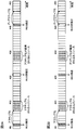
- FIGS. 2A and 2B are diagrams illustrating an example of a setting grant-based UL transmission control (for example, activation / deactivation).
- a setting grant-based UL transmission control for example, activation / deactivation.
- predetermined parameters for example, resources
- a dynamic DL signal for example, WUS or at least one of WUS and DCI 2 2
- RRC connection state also referred to as an RRC connection mode
- present invention is not limited to this and may be applied in other modes.
- the UE controls activation / deactivation of UL transmission based on the set grant based on whether or not WUS is detected.
- DCI is also used for activation / deactivation based on the configuration grant
- the UE does not monitor (eg, skip) the PDCCH configured for the DCI based on the detection of WUS. It may be controlled.
- the UE activates the configuration grant-based UL transmission when the configuration grant-based UL transmission (or the UL resource for the configuration grant base) detects WUS in the deactivation state. Also, when detecting the WUS, the UE may activate the UL transmission after skipping the monitoring of the PDCCH. This eliminates the need to monitor the PDCCH (or DCI), thereby reducing the load of the UE on reception processing.
- the UE may be configured to monitor the PDCCH when the setting grant-based UL transmission cannot detect WUS in the deactivation state. By this means, when the UE cannot detect WUS, the UE can activate UL transmission based on the set grant based on the DCI transmitted on the PDCCH.
- the UE may control the continuation or deactivation of the activated state based on whether or not a WUS is detected.
- the UE may control the continuation or deactivation of the activated state based on whether or not a WUS is detected.
- at least one of the following option 1 or option 2 may be used.
- the UE controls activation and deactivation of the set grant-based UL transmission based on WUS detection, and controls maintenance of activation based on WUS non-detection. For example, when the setting grant-based UL transmission does not detect WUS in the activation state, the UE performs the UL transmission process on the assumption that the activation state of the setting grant-based UL resource is maintained. On the other hand, the UE may determine that the setting grant-based UL transmission (or UL resource) is deactivated when the setting grant-based UL transmission detects WUS in the activated state.
- a predetermined period during which the UE monitors the WUS and tries to detect it may be notified from the base station to the UE in advance, or may be defined in the specification.
- the base station may use at least one of an upper layer (for example, RRC signaling) and downlink control information.
- FIG. 2A shows an example of a grant-based transmission control when option 1 is applied.
- FIG. 2A shows, as an example, a case where WUS is set in a 20-slot cycle (the start position is slot # 1).
- FIG. 2A shows a case where transmission of WUS and setting of UL resources are controlled in slot units, a time unit available for control is not limited to a slot, and may be a predetermined symbol unit.
- the UE activates the set grant-based UL transmission (or the set grant-based UL resource) that has been deactivated based on the WUS detected in slot # 1.
- the UE activates the set grant-based UL transmission (or the set grant-based UL resource) that has been deactivated based on the WUS detected in slot # 1.
- activated UL resources are set in slots # 7 to # 10.
- the UL resource for setting grant base may be set in the UE in advance by an upper layer (for example, RRC signaling or the like).
- the UE performs a setting grant-based UL transmission using the activated UL resource based on the presence / absence of traffic of the own terminal (the presence / absence of UL data to be transmitted) and the like. Further, when detecting the WUS, the UE may perform control to skip monitoring of the PDCCH used for transmission of the predetermined DCI.
- the predetermined DCI may be a DCI that instructs activation of at least the set grant-based UL transmission.
- the UE monitors the WUS transmitted at a predetermined timing (in this case, slot # 21).
- a predetermined timing in this case, slot # 21.
- the UE corresponds to a case in which the setting grant-based UL transmission does not detect WUS in the activation state.
- the UE performs UL transmission processing on the assumption that the activation state of the UL resource based on the set grant is maintained.
- the UE may perform control to skip monitoring of the PDCCH used for transmission of the predetermined DCI.
- the predetermined DCI may be a DCI that instructs activation of at least the set grant-based UL transmission.
- the UE monitors the WUS transmitted at a predetermined timing (here, slot # 41).
- a predetermined timing here, slot # 41.
- the UE detects WUS in slot # 41.
- the UE corresponds to a case where WUS is detected when UL transmission based on the set grant is in the activated state.
- the UE deactivates the set grant-based UL resource that has been in the activated state.
- the UE determines that UL resources that can be set in slots # 47- # 50 are deactivated (unusable).
- the processing load on the UE can be reduced.
- DCI PDCCH
- the UE controls activation or maintenance of activation of the set grant-based UL transmission based on detection of WUS, and controls deactivation based on non-detection of WUS. For example, when the UE detects WUS in the activation state of the setting grant-based UL transmission, the UE performs the UL transmission process on the assumption that the activation state of the setting grant-based UL resource is maintained. On the other hand, the UE may determine that the configuration grant-based UL transmission (or UL resource) is deactivated if the configuration grant-based UL transmission cannot detect WUS in the activated state.
- FIG. 2B shows an example of a grant-based transmission control when option 2 is applied.
- FIG. 2B shows, as an example, a case where WUS is set in a cycle of 20 slots (the start position is slot # 1).
- FIG. 2B shows a case where transmission of WUS and setting of UL resources are controlled in slot units, a time unit available for control is not limited to a slot, and may be a predetermined symbol unit.
- the UE activates the set grant-based UL transmission (or the set grant-based UL resource) in the deactivated state based on the WUS detected in slot # 1.
- the UE activates the set grant-based UL transmission (or the set grant-based UL resource) in the deactivated state based on the WUS detected in slot # 1.
- activated UL resources are set in slots # 7 to # 10.
- the UL resource for setting grant base may be set in the UE in advance by an upper layer (for example, RRC signaling or the like).
- the UE performs a setting grant-based UL transmission using the activated UL resource based on the presence / absence of traffic of the own terminal (the presence / absence of UL data to be transmitted) and the like. Further, when detecting the WUS, the UE may perform control to skip monitoring of the PDCCH used for transmission of the predetermined DCI.
- the predetermined DCI may be a DCI that instructs activation of at least the set grant-based UL transmission.
- the UE monitors the WUS transmitted at a predetermined timing (in this case, slot # 21).
- a predetermined timing in this case, slot # 21.
- the UE detects WUS in slot # 21. That is, the UE corresponds to a case where the UE performs WUS in the activated state of the UL transmission based on the set grant.
- the UE performs UL transmission processing on the assumption that the activation state of the UL resource based on the set grant is maintained.
- the UE may control to skip monitoring of the PDCCH used for transmitting the predetermined DCI.
- the predetermined DCI may be a DCI that instructs activation of at least the set grant-based UL transmission.
- the UE monitors the WUS transmitted at a predetermined timing (here, slot # 41).
- a case is shown in which the UE does not detect WUS in slot # 41. That is, the UE corresponds to a case where WUS cannot be detected (non-detected) in a state where the setting grant-based UL transmission is in the activated state.
- the UE deactivates the set grant-based UL resource that has been in the activated state.
- the UE determines that UL resources that can be set in slots # 47- # 50 are deactivated (unusable).
- the processing load on the UE can be reduced.
- DCI PDCCH
- activation or maintenance of activation is performed based on detection of WUS, and deactivation is performed based on non-detection of WUS, so that activation is maintained even when WUS is missed. Can be prevented.
- the predetermined DL signal or DL channel shown in the second mode may be applied in the first mode.
- WWUS used in the idle state may be used (also referred to as reuse) in the RRC connection state as a predetermined DL signal or DL channel applied to activation / deactivation of transmission based on the set grant.
- the WUS used in the idle state may be, for example, a signal used to change the state of the UE from the DRX mode to the non-DRX mode.
- the UE differs in operation when detecting WUS in the idle state (RRC idle mode, also referred to as RRC_IDLE @ mode) and in detecting the WUS in the RRC connected state (RRC connected mode, also referred to as RRC_CONNECTED @ mode). May be controlled.
- RRC idle mode also referred to as RRC_IDLE @ mode
- RRC connected mode also referred to as RRC_CONNECTED @ mode
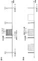
- FIG. 3A is a diagram showing an example of a UE operation at the time of WUS reception in an idle state.
- the UE may transition to the non-DRX mode (for example, the connection mode).
- WUS in the idle state RRC idle mode, also referred to as RRC_IDLE @ mode
- RRC idle mode also referred to as RRC_IDLE @ mode
- the UE may control to monitor the control resource set (PDCCH) to which the DCI for scheduling the paging message is transmitted (see FIG. 3A).
- PDCCH control resource set
- WUS resources are set at a predetermined cycle (for example, DTX cycle), and the UE monitors WUS at a predetermined cycle.
- the UE determines that monitoring of the control resource set for paging (or PDCCH) has been triggered or activated, and monitors the control resource set.
- the resources of the control resource set may be defined in advance in the specification, or may be notified from the base station to the UE.
- the UE may receive a PDSCH (or paging message) scheduled on DCI transmitted on a control resource set (or PDCCH).
- the UE monitors the PDCCH based on the detection of WUS in the idle state.
- FIG. 3B is a diagram showing an example of the UE operation at the time of WUS reception in the RRC connection state.
- the UE When detecting the WUS in the RRC connection state, the UE performs at least one of activation / deactivation of the UL transmission (or UL resource) based on the set grant and monitoring skip of the PDCCH.
- WUS resources are set at a predetermined cycle, and the UE monitors WUS at a predetermined cycle.
- the UE performs at least one of activation of the setting grant-based UL transmission, maintenance of activation, deactivation, and skip of PDCCH monitoring (see FIG. 2).
- FIG. 2 a case where activation based on a set grant or maintenance of activation is performed based on detection of WUS is shown.
- the UE may skip monitoring of the PDCCH based on detection of WUS.
- the UE may control the UE operation by changing the interpretation of the function (or role) of the WUS according to the connection state (connection mode).
- the setting grant-based activation is achieved by simplifying the WUS receiving process (for example, performing detection by taking correlation without performing decoding process) than the PDCCH receiving process (for example, performing decoding process). / Load of UE operation in deactivation can be reduced.
- FIG. 3 shows a case in which the WUS cycle in the idle state (for example, the cycle at which the UE performs monitoring) and the WUS cycle in the RRC connection state are set to be the same, but the present invention is not limited to this.
- the configuration (for example, cycle) of the WUS in the idle state and the configuration (for example, cycle) of the WUS in the RRC connection state may be set differently.
- the WUS cycle in the idle state and the WUS cycle in the RRC connection state may be set independently.
- the base station may separately set the WUS configuration such as the WUS cycle in the idle state and the configuration such as the WUS cycle in the RRC connection state in the UE in an upper layer (for example, RRC signaling). .
- At least one of a WUS configuration such as a WUS cycle in an idle state and a configuration such as a WUS cycle in an RRC connection state may be notified on a UE-specific basis, or a predetermined UE group (UE-specific). UE-group-based @ manner) may be notified.
- the WUS in the idle state and the WUS in the RRC connection state may be defined using at least one of different configurations and sequences.
- different configurations for example, cycle, offset, and the like
- the WUS in the idle state and the WUS in the RRC connection state may be generated using different sequences.
- a DL signal or a channel used for activation / deactivation based on the set grant in the RRC connection state may be referred to by a name different from WUS.
- the interval between the WUS and the UL resource may be determined based on a predetermined condition.
- the interval (also referred to as an offset) between the WUS and the UL resource may be determined in consideration of the monitoring periods of the WUS, the PDCCH, and the PDCCH.
- the UE sets the WUS in the idle state, the position of the PDCCH to start monitoring by the WUS, and the monitoring period of the PDCCH. May be considered in determining the position of the UL resource. For example, it may be assumed that the UL resource is set after the monitoring period of the PDCCH.
- the WUS and UL resources in the RRC connection state may be set in adjacent time periods (for example, slots or symbols). .
- the detection of the WUS in the idle state and the RRC connection state is performed by notifying the UE of information on one WUS configuration. It can be carried out.
- the WUS configuration in the idle state and the WUS configuration in the RRC connection state are separately set, the WUS configuration in the idle state and the WUS configuration in the RRC connection state are flexibly set according to the respective applications or purposes. be able to.
- Wireless communication system Wireless communication system
- the configuration of the wireless communication system according to the present embodiment will be described.
- the above-described aspects are applied.
- each aspect may be used independently and may be combined.
- FIG. 4 is a schematic configuration diagram of the wireless communication system according to the present embodiment.
- the wireless communication system 1 is an example in which an LTE-based system is adopted in a network domain of a machine communication system, but is not limited thereto.
- the wireless communication system 1 may adopt an NR-based system of a machine communication system.
- carrier aggregation (CA) and / or dual connectivity (DC) integrating a plurality of component carriers (CC) can be applied.
- the LTE system is set to a system band from a minimum of 1.4 MHz to a maximum of 20 MHz for both downlink and uplink, but is not limited to this configuration.
- the wireless communication system 1 includes SUPER @ 3G, LTE-A (LTE-Advanced), IMT-Advanced, 4G (4th generation mobile communication system), 5G (5th generation mobile communication system), NR (New Radio), and FRA (New Radio). It may be called Future @ Radio @ Access, New-RAT (Radio @ Access @ Technology), IoT, or the like, or a system that realizes these.
- the wireless communication system 1 includes a wireless base station 10 and a plurality of user terminals 20A, 20B, and 20C wirelessly connected to the wireless base station 10.
- the wireless base station 10 is connected to the upper station device 30 and is connected to the core network 40 via the upper station device 30.
- the upper station device 30 includes, for example, an access gateway device, a radio network controller (RNC), a mobility management entity (MME), and the like, but is not limited thereto.
- the user terminal 20 can communicate with the radio base station 10 in the cell 50.
- the user terminal 20 may be a user terminal (for example, a UE of category 0, 1 or the like) in which the maximum bandwidth usable in one CC is not limited.
- the user terminal 20 may be a user terminal (for example, a UE of a category M, M1 or M2, or an MTC terminal) in which the maximum bandwidth that can be used in one CC is limited.
- the user terminal 20 may be a user terminal (UE of category N, N1 or N2, NB-IoT terminal) whose maximum bandwidth is more restricted than the MTC terminal.
- orthogonal frequency division multiple access Orthogonal Frequency Division Multiple Access
- SC-FDMA Single-DMA
- Carrier Frequency Division Multiple Access is applied.
- OFDMA is a multicarrier transmission scheme in which a frequency band is divided into a plurality of narrow frequency bands (subcarriers), and data is mapped to each subcarrier to perform communication.
- SC-FDMA is a single-carrier transmission scheme that divides the system bandwidth into bands each consisting of one or continuous resource blocks for each terminal, and reduces interference between terminals by using different bands for a plurality of terminals. is there.
- the uplink and downlink radio access schemes are not limited to these combinations. For example, OFDMA may be used in the uplink.
- a downlink shared channel (PDSCH: Physical Downlink Shared Channel, NPDSCH: Narrowband PDSCH, PDSCH and NPDSCH is collectively referred to as PDSCH) shared by each user terminal 20 as a downlink channel.
- a broadcast channel (PBCH: Physical @ Broadcast @ Channel), a downlink L1 / L2 control channel, and the like are used.
- the PDSCH transmits user data, upper layer control information, and a predetermined SIB (System Information Block).
- SIB System Information Block
- MIB Master ⁇ Information ⁇ Block
- the downlink L1 / L2 control channel includes a downlink control channel (PDCCH: Physical Downlink Control Channel, MPDCCH: MTC PDCCH, NPDCCH: Narrowband PDCCH, PDCCH, MPDCCH, NPDCCH; collectively referred to as PDCCH).
- Downlink control information including scheduling information (DCI: Downlink Control Information) and the like are transmitted by the PDCCH.
- an uplink shared channel shared by each user terminal 20 (PUSCH: Physical Uplink Shared Channel, NPUSCH: Narrowband PUSCH, PDSCH and NPUSCH is collectively referred to as PUSCH), uplink An L1 / L2 control channel (PUCCH: Physical Uplink Control Channel), a random access channel (PRACH: Physical Random Access Channel, NPRACH: Narrowband PRACH, and PRACH when collectively referring to PRACH and NPRACH) are used.
- PUSCH may be called an uplink data channel.
- PUSCH transmits user data and higher layer control information.
- downlink radio quality information CQI: Channel ⁇ Quality ⁇ Indicator
- HARQ-ACK retransmission control information
- the PRACH transmits a random access preamble for establishing a connection with a cell.
- the channel for the MTC terminal / NB-IoT terminal may be represented by adding “M” indicating MTC or “NB” indicating NB-IoT, and the PDCCH / MTC terminal / NB-IoT terminal.
- the EPDCCH, PDSCH, PUCCH, PUSCH may be called M (NB) -PDCCH, M (NB) -PDSCH, M (NB) -PUCCH, M (NB) -PUSCH, etc., respectively.
- PDCCH, PDSCH, PUCCH, and PUSCH are simply referred to as PDCCH, PDSCH, PUCCH, and PUSCH.
- a cell-specific reference signal CRS: Cell-specific Reference Signal
- CSI-RS Channel State Information-Reference Signal
- DMRS Demodulation Reference Signal
- PRS Positioning Reference Signal
- a reference signal for measurement SRS: Sounding Reference Signal
- DMRS reference signal for demodulation
- the DMRS may be called a user terminal specific reference signal (UE-specific Reference Signal). Further, the transmitted reference signal is not limited to these.
- FIG. 5 is a diagram showing an example of the overall configuration of the radio base station according to the present embodiment.
- the wireless base station 10 includes at least a plurality of transmitting / receiving antennas 101, an amplifier unit 102, a transmitting / receiving unit 103, a baseband signal processing unit 104, a call processing unit 105, and a transmission path interface 106.
- the baseband signal processing unit 104 regarding user data, processing of a PDCP (Packet Data Convergence Protocol) layer, division / combination of user data, transmission processing of an RLC layer such as RLC (Radio Link Control) retransmission control, and MAC (Medium Access) Control) Transmission processing such as retransmission control (for example, HARQ (Hybrid Automatic Repeat Repeat request) transmission processing), scheduling, transmission format selection, channel coding, inverse fast Fourier transform (IFFT) processing, and precoding processing Is performed and transferred to each transmitting / receiving unit 103.
- the downlink control signal is also subjected to transmission processing such as channel coding and inverse fast Fourier transform, and is transferred to each transmitting / receiving section 103.
- Each transmission / reception section 103 converts the baseband signal pre-coded and output from the baseband signal processing section 104 for each antenna into a radio frequency band, and transmits the radio frequency band.
- the transmission / reception unit 103 can be configured by a transmitter / receiver, a transmission / reception circuit, or a transmission / reception device described based on common recognition in the technical field according to the present invention. Note that the transmission / reception unit 103 may be configured as an integrated transmission / reception unit, or may be configured from a transmission unit and a reception unit.
- the radio frequency signal frequency-converted by the transmission / reception unit 103 is amplified by the amplifier unit 102 and transmitted from the transmission / reception antenna 101.
- the transmission / reception unit 103 can transmit / receive various signals in a bandwidth (for example, 180 kHz or 200 kHz) (also referred to as a narrow band) that is limited by a system bandwidth (for example, 20 MHz).
- the radio frequency signal received by each transmitting / receiving antenna 101 is amplified by the amplifier unit 102.
- Each transmitting / receiving section 103 receives the upstream signal amplified by the amplifier section 102.
- Transmitting / receiving section 103 frequency-converts the received signal into a baseband signal and outputs the baseband signal to baseband signal processing section 104.
- the baseband signal processing unit 104 performs fast Fourier transform (FFT: Fast Fourier Transform), inverse discrete Fourier transform (IDFT), and error correction on user data included in the input uplink signal. Decoding, reception processing of MAC retransmission control, reception processing of the RLC layer and PDCP layer are performed, and the data is transferred to the upper station apparatus 30 via the transmission path interface 106.
- the call processing unit 105 performs call processing such as setting and release of a communication channel, state management of the wireless base station 10, and management of wireless resources.
- the transmission path interface 106 transmits and receives signals to and from the higher-level station device 30 via a predetermined interface.
- the transmission path interface 106 transmits and receives signals (backhaul signaling) to and from another wireless base station 10 via an interface between base stations (for example, an optical fiber compliant with CPRI (Common Public Radio Interface), an X2 interface). You may.
- CPRI Common Public Radio Interface
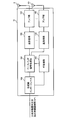
- FIG. 6 is a diagram showing an example of a functional configuration of the radio base station according to the present embodiment. Note that, in the present example, functional blocks of characteristic portions in the present embodiment are mainly shown, and it may be assumed that the wireless base station 10 also has other functional blocks necessary for wireless communication.
- the baseband signal processing unit 104 includes at least a control unit 301, a transmission signal generation unit 302, a mapping unit 303, a reception signal processing unit 304, and a measurement unit 305.
- the control unit 301 controls the entire wireless base station 10.
- the control unit 301 can be configured by a controller, a control circuit, or a control device described based on common recognition in the technical field according to the present invention.
- the control unit 301 controls, for example, generation of a signal by the transmission signal generation unit 302 and allocation of a signal by the mapping unit 303. Further, the control unit 301 controls a signal reception process by the reception signal processing unit 304 and a signal measurement by the measurement unit 305.
- the control unit 301 controls resource allocation (scheduling) of system information, PDSCH, and PUSCH. Also, it controls resource allocation for synchronization signals (for example, PSS (Primary Synchronization Signal) / SSS (Secondary Synchronization Signal), NB-SS) and downlink reference signals such as CRS, CSI-RS, and DM-RS.
- synchronization signals for example, PSS (Primary Synchronization Signal) / SSS (Secondary Synchronization Signal), NB-SS
- CRS Channel Reference Signal
- CSI-RS Code Division Multiple Access
- DM-RS Downlink Reference Signal
- the control unit 301 controls the transmission signal generation unit 302 and the mapping unit 303 so that various signals are allocated to narrow bands and transmitted to the user terminal 20.
- the control unit 301 includes, for example, broadcast information (for example, MIB, SIB, MIB-NB, SIB-NB, etc.), a downlink control channel (for example, PDCCH, MPDCCH, NPDCCH, etc.), a downlink shared channel (for example, PDSCH) , NPDSCH, etc.) are transmitted in a narrow band.
- the narrow band (NB) may be, for example, 6 PRB (1.4 MHz) or 1 PRB (200 kHz or 180 kHz).
- the control unit 301 controls reception of an uplink shared channel (for example, PUSCH, NPUSCH) in cooperation with at least one of the transmission / reception unit 103, the reception signal processing unit 302, and the measurement unit 305. Further, the control unit 301 controls transmission of a downlink shared channel (for example, PDSCH, NPDSCH) in cooperation with at least one of the transmission signal generation unit 302, the mapping unit 303, and the transmission / reception unit 103. In the downlink shared channel, at least one of downlink data and higher layer control information may be transmitted.
- an uplink shared channel for example, PUSCH, NPUSCH
- the control unit 301 controls transmission of a downlink shared channel (for example, PDSCH, NPDSCH) in cooperation with at least one of the transmission signal generation unit 302, the mapping unit 303, and the transmission / reception unit 103.
- a downlink shared channel for example, PDSCH, NPDSCH
- at least one of downlink data and higher layer control information may be transmitted.
- the transmission signal generation unit 302 generates a downlink signal (for example, a downlink control channel, a downlink shared channel, a downlink reference signal, a synchronization signal, a broadcast channel, etc.) based on an instruction from the control unit 301, and sends the downlink signal to the mapping unit 303. Output.
- the transmission signal generation unit 302 can be configured from a signal generator, a signal generation circuit, or a signal generation device described based on common recognition in the technical field according to the present invention.
- the transmission signal generation unit 302 generates DCI (also referred to as DL assignment, UL grant, etc.) based on, for example, an instruction from the control unit 301.
- DCI also referred to as DL assignment, UL grant, etc.
- the downlink shared channel is subjected to an encoding process and a modulation process according to an encoding rate, a modulation scheme, and the like determined based on channel state information (CSI) from each user terminal 20 and the like.
- CSI channel state information
- the mapping unit 303 converts the downlink signal generated by the transmission signal generation unit 302 based on an instruction from the control unit 301 into a predetermined frequency resource (for example, one or more PRBs in a narrow band or one or more PRBs in one PRB). (Subcarrier) and outputs the result to the transmission / reception section 103.
- the mapping unit 303 can be composed of a mapper, a mapping circuit, or a mapping device described based on common recognition in the technical field according to the present invention.
- the reception signal processing unit 304 performs reception processing (for example, demapping, demodulation, and decoding) on the reception signal input from the transmission / reception unit 103.
- the received signal is, for example, an uplink signal transmitted from the user terminal 20 (for example, an uplink control channel, an uplink shared channel, an uplink reference signal, and the like).
- the reception signal processing unit 304 can be configured from a signal processor, a signal processing circuit, or a signal processing device described based on common recognition in the technical field according to the present invention.
- the reception signal processing unit 304 outputs the information decoded by the reception processing to the control unit 301. Further, the reception signal processing unit 304 outputs the reception signal and the signal after the reception processing to the measurement unit 305.
- the measurement unit 305 performs measurement on the received signal.
- the measurement unit 305 can be configured from a measurement device, a measurement circuit, or a measurement device described based on common recognition in the technical field according to the present invention.
- the measurement unit 305 may measure the received power of the signal (for example, RSRP (Reference Signal Received Power)), the reception quality (for example, RSRQ (Reference Signal Received Quality)), the channel state, and the like.
- the measurement result may be output to the control unit 301.
- the transmitting / receiving section 103 may transmit a wake-up signal (WUS: Wake-Up-Signal).
- the transmission / reception unit 103 may transmit setting information on UL transmission based on a setting grant by higher layer signaling.
- the control unit 301 may use the WUS to instruct the UE to activate / deactivate the UL transmission based on the set grant.
- FIG. 7 is a diagram showing an example of the overall configuration of the user terminal according to the present embodiment. Although a detailed description is omitted here, a normal LTE terminal may operate as an NB-IoT terminal or an MTC terminal. The user terminal may support only half-duplex communication (half Duplex), or may support both half-duplex communication and full-duplex communication (full Duplex).
- the user terminal 20 includes at least a transmitting / receiving antenna 201, an amplifier unit 202, a transmitting / receiving unit 203, a baseband signal processing unit 204, and an application unit 205. Further, the user terminal 20 may include a plurality of transmission / reception antennas 201, amplifier units 202, transmission / reception units 203, and the like.
- the radio frequency signal received by the transmitting / receiving antenna 201 is amplified by the amplifier unit 202.
- the transmission / reception unit 203 receives the downlink signal amplified by the amplifier unit 202.
- the number of transmission / reception antennas 201 may be one or more.
- the transmitting / receiving section 203 frequency-converts the received signal into a baseband signal and outputs the baseband signal to the baseband signal processing section 204.
- the transmission / reception unit 203 can be configured from a transmitter / receiver, a transmission / reception circuit, or a transmission / reception device described based on common recognition in the technical field according to the present invention. Note that the transmission / reception unit 203 may be configured as an integrated transmission / reception unit, or may be configured from a transmission unit and a reception unit.
- the baseband signal processing unit 204 performs FFT processing, error correction decoding, reception processing for retransmission control, and the like on the input baseband signal.
- the downlink user data is transferred to the application unit 205.
- the application unit 205 performs processing related to a layer higher than the physical layer and the MAC layer. In addition, broadcast information among downlink data is also transferred to the application unit 205.
- uplink user data is input from the application unit 205 to the baseband signal processing unit 204.
- the baseband signal processing unit 204 performs retransmission control information (HARQ-ACK) transmission processing, channel coding, precoding, discrete Fourier transform (DFT) processing, IFFT processing, and the like. Is forwarded to HARQ-ACK.
- HARQ-ACK retransmission control information
- DFT discrete Fourier transform
- IFFT IFFT processing
- the transmission / reception unit 203 converts the baseband signal output from the baseband signal processing unit 204 into a radio frequency band and transmits the radio frequency band.
- the radio frequency signal frequency-converted by the transmission / reception unit 203 is amplified by the amplifier unit 202 and transmitted from the transmission / reception antenna 201.
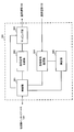
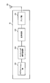
- FIG. 8 is a diagram showing an example of a functional configuration of the user terminal according to the present embodiment.
- functional blocks of characteristic portions in the present embodiment are mainly shown, and it is assumed that the user terminal 20 also has other functional blocks necessary for wireless communication.
- the baseband signal processing unit 204 of the user terminal 20 includes at least a control unit 401, a transmission signal generation unit (generation unit) 402, a mapping unit 403, a reception signal processing unit 404, and a measurement unit 405. I have.
- the control unit 401 controls the entire user terminal 20.
- the control unit 401 can be configured by a controller, a control circuit, or a control device that is described based on common recognition in the technical field according to the present invention.
- the control unit 401 controls, for example, generation of a signal by the transmission signal generation unit 402 and assignment of a signal by the mapping unit 403. Further, the control unit 401 controls a signal reception process by the reception signal processing unit 404 and a signal measurement by the measurement unit 405.
- the control unit 401 acquires from the reception signal processing unit 404 a downlink signal (for example, a downlink control channel, a downlink shared channel, a downlink reference signal, a synchronization signal, a broadcast channel, etc.) transmitted from the wireless base station 10.
- the control unit 401 controls generation of uplink control information (UCI) such as retransmission control information (HARQ-ACK, ACK / NACK, ACK) and channel state information (CSI) and uplink data based on the downlink signal.
- UCI uplink control information
- HARQ-ACK retransmission control information
- ACK / NACK ACK
- CSI channel state information
- the control unit 401 also controls transmission of an uplink shared channel (for example, PUSCH, NPUSCH) in cooperation with at least one of the transmission / reception unit 203, the transmission signal generation unit 402, and the mapping unit 403.
- the control unit 401 controls transmission of a downlink shared channel (for example, PDSCH, NPDSCH) in cooperation with at least one of the transmission / reception unit 203, the reception signal processing unit 404, and the measurement unit 405.
- a downlink shared channel for example, PDSCH, NPDSCH
- the downlink shared channel at least one of downlink data and higher layer control information may be transmitted.
- Transmission signal generation section 402 generates an uplink signal (for example, an uplink control channel, an uplink shared channel, an uplink reference signal, etc.) based on an instruction from control section 401, and outputs the generated uplink signal to mapping section 403.
- the transmission signal generation unit 402 can be configured from a signal generator, a signal generation circuit, or a signal generation device described based on common recognition in the technical field according to the present invention.
- the transmission signal generation unit 402 generates uplink control information (UCI) and / or uplink data based on, for example, an instruction from the control unit 401. Further, transmission signal generating section 402 generates a PUSCH for transmitting UCI and / or uplink data based on an instruction from control section 401.
- UCI uplink control information
- PUSCH PUSCH for transmitting UCI and / or uplink data based on an instruction from control section 401.
- Mapping section 403 maps the uplink signal generated by transmission signal generation section 402 to a predetermined resource based on an instruction from control section 401, and outputs the result to transmission / reception section 203.
- the mapping unit 403 can be composed of a mapper, a mapping circuit, or a mapping device described based on common recognition in the technical field according to the present invention.
- the reception signal processing unit 404 performs reception processing (for example, demapping, demodulation, and decoding) on the reception signal input from the transmission / reception unit 203.
- the received signal is, for example, a downlink signal (a downlink control signal, a downlink data signal, a downlink reference signal, etc.) transmitted from the radio base station 10.
- the reception signal processing unit 404 can be configured from a signal processor, a signal processing circuit, or a signal processing device described based on common recognition in the technical field according to the present invention.
- the reception signal processing unit 404 outputs the information decoded by the reception processing to the control unit 401.
- the reception signal processing unit 404 outputs, for example, broadcast information, system information, RRC signaling, DCI, and the like to the control unit 401. Further, the reception signal processing unit 404 outputs the reception signal and the signal after the reception processing to the measurement unit 405.
- the measuring unit 405 measures the received signal.
- the measurement unit 405 can be configured from a measurement device, a measurement circuit, or a measurement device described based on common recognition in the technical field according to the present invention.
- the measurement unit 405 may measure, for example, the received power (for example, RSRP), received quality (for example, RSRQ), channel state, and the like of the received signal.
- the measurement result may be output to the control unit 401.
- the transmitting / receiving unit 203 may detect or monitor a wake-up signal (WUS: Wake-Up-Signal). In addition, the transmission / reception unit 203 may receive setting information related to setting grant-based UL transmission by higher layer signaling.
- WUS Wake-Up-Signal
- the control unit 401 controls at least one of activation or deactivation of an uplink shared channel transmission resource that is not scheduled by downlink control information and monitoring of a downlink control channel based on whether WUS is detected. You may.
- control unit 401 when the control unit 401 detects WUS in a state where the uplink shared channel transmission resource is deactivated, the control unit 401 may skip monitoring of the downlink control channel and activate the uplink shared channel transmission resource.
- control section 401 maintains activation of resources for uplink shared channel transmission when WUS is not detected, and controls resources for uplink shared channel transmission when WUS is detected. May be deactivated.
- control section 401 maintains activation of resources for uplink shared channel transmission when WUS is detected, and controls resources for uplink shared channel transmission when WUS is not detected. May be deactivated.
- control unit 401 may activate or deactivate the resource for transmitting the uplink shared channel based on the WUS.
- control unit 401 When control unit 401 receives WUS in the RRC idle state, control unit 401 may activate monitoring of a downlink control channel for receiving a paging message based on WUS.
- each functional block may be realized using one device physically or logically coupled, or directly or indirectly (for example, two or more devices physically or logically separated from each other). , Wired, wireless, etc.), and may be implemented using these multiple devices.
- the functional block may be realized by combining one device or the plurality of devices with software.
- the functions include judgment, determination, judgment, calculation, calculation, processing, derivation, investigation, search, confirmation, reception, transmission, output, access, resolution, selection, selection, establishment, comparison, assumption, expectation, and deemed. , Broadcasting, notifying, communicating, forwarding, configuring, reconfiguring, allocating, mapping, assigning, etc.
- a functional block (configuration unit) that causes transmission to function may be referred to as a transmitting unit (transmitting unit), a transmitter (transmitter), or the like.
- the realization method is not particularly limited.
- a base station, a user terminal, and the like may function as a computer that performs processing of the wireless communication method according to the present disclosure.
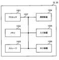
- FIG. 9 is a diagram illustrating an example of a hardware configuration of a base station and a user terminal according to one embodiment.
- the above-described base station 10 and user terminal 20 may be physically configured as a computer device including a processor 1001, a memory 1002, a storage 1003, a communication device 1004, an input device 1005, an output device 1006, a bus 1007, and the like. .
- the term “apparatus” can be read as a circuit, a device, a unit, or the like.
- the hardware configuration of the base station 10 and the user terminal 20 may be configured to include one or more of the devices illustrated in the drawing, or may be configured to exclude some of the devices.
- processor 1001 may be implemented by one or more chips.
- the functions of the base station 10 and the user terminal 20 are performed, for example, by reading predetermined software (program) on hardware such as the processor 1001 and the memory 1002 so that the processor 1001 performs an arithmetic operation and communicates via the communication device 1004. And controlling at least one of reading and writing of data in the memory 1002 and the storage 1003.
- predetermined software program
- the processor 1001 performs an arithmetic operation and communicates via the communication device 1004.
- the processor 1001 controls the entire computer by operating an operating system, for example.
- the processor 1001 may be configured by a central processing unit (CPU: Central Processing Unit) including an interface with a peripheral device, a control device, an arithmetic device, a register, and the like.
- CPU Central Processing Unit
- the above-described baseband signal processing unit 104 (204), call processing unit 105, and the like may be realized by the processor 1001.
- the processor 1001 reads out a program (program code), a software module, data, and the like from at least one of the storage 1003 and the communication device 1004 to the memory 1002, and executes various processes according to these.
- a program program code
- a program that causes a computer to execute at least a part of the operation described in the above embodiment is used.
- the control unit 401 of the user terminal 20 may be implemented by a control program stored in the memory 1002 and operated by the processor 1001, and other functional blocks may be implemented similarly.
- the memory 1002 is a computer-readable recording medium, for example, at least one of ROM (Read Only Memory), EPROM (Erasable Programmable ROM), EEPROM (Electrically EPROM), RAM (Random Access Memory), and other appropriate storage media. It may be constituted by one.
- the memory 1002 may be called a register, a cache, a main memory (main storage device), or the like.
- the memory 1002 can store a program (program code), a software module, and the like that can be executed to execute the wireless communication method according to an embodiment of the present disclosure.
- the storage 1003 is a computer-readable recording medium such as a flexible disk, a floppy (registered trademark) disk, a magneto-optical disk (for example, a compact disk (CD-ROM (Compact Disc) ROM, etc.), a digital versatile disc, At least one of a Blu-ray (registered trademark) disk, a removable disk, a hard disk drive, a smart card, a flash memory device (eg, a card, a stick, a key drive), a magnetic stripe, a database, a server, and other suitable storage media. May be configured.
- the storage 1003 may be called an auxiliary storage device.
- the communication device 1004 is hardware (transmission / reception device) for performing communication between computers via at least one of a wired network and a wireless network, and is also referred to as, for example, a network device, a network controller, a network card, a communication module, or the like.
- the communication device 1004 includes a high-frequency switch, a duplexer, a filter, a frequency synthesizer, and the like, for example, in order to realize at least one of frequency division duplex (FDD: Frequency Division Duplex) and time division duplex (TDD: Time Division Duplex). May be configured.
- FDD Frequency Division Duplex
- TDD Time Division Duplex
- the transmission / reception antenna 101 (201), the amplifier unit 102 (202), the transmission / reception unit 103 (203), the transmission path interface 106, and the like may be realized by the communication device 1004.
- the transmission / reception unit 103 may be mounted physically or logically separated between the transmission unit 103a and the reception unit 103b.
- the input device 1005 is an input device (for example, a keyboard, a mouse, a microphone, a switch, a button, a sensor, and the like) that receives an external input.
- the output device 1006 is an output device that performs output to the outside (for example, a display, a speaker, an LED (Light Emitting Diode) lamp, and the like). Note that the input device 1005 and the output device 1006 may have an integrated configuration (for example, a touch panel).
- the devices such as the processor 1001 and the memory 1002 are connected by a bus 1007 for communicating information.
- the bus 1007 may be configured using a single bus, or may be configured using a different bus for each device.
- the base station 10 and the user terminal 20 include hardware such as a microprocessor, a digital signal processor (DSP: Digital Signal Processor), an ASIC (Application Specific Integrated Circuit), a PLD (Programmable Logic Device), and an FPGA (Field Programmable Gate Array). It may be configured to include hardware, and some or all of the functional blocks may be realized using the hardware. For example, the processor 1001 may be implemented using at least one of these pieces of hardware.
- DSP Digital Signal Processor
- ASIC Application Specific Integrated Circuit
- PLD Programmable Logic Device
- FPGA Field Programmable Gate Array
- the channel and the symbol may be a signal (signaling).
- the signal may be a message.
- the reference signal may be abbreviated as RS (Reference Signal), and may be referred to as a pilot, a pilot signal, or the like according to an applied standard.
- a component carrier (CC: Component Carrier) may be called a cell, a frequency carrier, a carrier frequency, or the like.
- a radio frame may be configured by one or more periods (frames) in the time domain.
- the one or more respective periods (frames) forming the radio frame may be referred to as a subframe.
- a subframe may be configured by one or more slots in the time domain.
- the subframe may be of a fixed length of time (eg, 1 ms) that does not depend on numerology.
- the new melology may be a communication parameter applied to at least one of transmission and reception of a certain signal or channel.
- Numerology includes, for example, subcarrier interval (SCS: SubCarrier @ Spacing), bandwidth, symbol length, cyclic prefix length, transmission time interval (TTI: Transmission @ Time @ Interval), number of symbols per TTI, radio frame configuration, transmission and reception.
- SCS SubCarrier @ Spacing
- TTI Transmission @ Time @ Interval
- TTI Transmission @ Time @ Interval
- radio frame configuration transmission and reception.
- At least one of a specific filtering process performed by the transceiver in the frequency domain and a specific windowing process performed by the transceiver in the time domain may be indicated.
- the slot may be configured by one or a plurality of symbols (OFDM (Orthogonal Frequency Division Multiplexing) symbol, SC-FDMA (Single Carrier Frequency Division Multiple Access) symbol, etc.) in the time domain. Further, the slot may be a time unit based on numerology.
- OFDM Orthogonal Frequency Division Multiplexing
- SC-FDMA Single Carrier Frequency Division Multiple Access
- the slot may include a plurality of mini slots.
- Each minislot may be constituted by one or more symbols in the time domain.
- the mini-slot may be called a sub-slot.
- a minislot may be made up of a smaller number of symbols than slots.
- a PDSCH (or PUSCH) transmitted in time units larger than minislots may be referred to as PDSCH (PUSCH) mapping type A.
- a PDSCH (or PUSCH) transmitted using a minislot may be referred to as a PDSCH (PUSCH) mapping type B.
- Radio frames, subframes, slots, minislots, and symbols all represent time units when transmitting signals.
- the radio frame, the subframe, the slot, the minislot, and the symbol may have different names corresponding to each. Note that time units such as frames, subframes, slots, minislots, and symbols in the present disclosure may be interchanged with each other.
- one subframe may be called a transmission time interval (TTI: Transmission @ Time @ Interval)
- TTI Transmission @ Time @ Interval
- TTI Transmission Time interval
- a plurality of consecutive subframes may be called a TTI
- one slot or one minislot is called a TTI.
- You may. That is, at least one of the subframe and the TTI may be a subframe (1 ms) in the existing LTE, a period shorter than 1 ms (for example, 1 to 13 symbols), or a period longer than 1 ms. It may be.
- the unit representing the TTI may be called a slot, a minislot, or the like instead of a subframe.
- the TTI refers to, for example, a minimum time unit of scheduling in wireless communication.
- the base station performs scheduling for allocating radio resources (frequency bandwidth, transmission power, and the like that can be used in each user terminal) to each user terminal in TTI units.
- radio resources frequency bandwidth, transmission power, and the like that can be used in each user terminal
- the TTI may be a transmission time unit such as a channel-encoded data packet (transport block), a code block, or a code word, or may be a processing unit such as scheduling and link adaptation. Note that when a TTI is given, a time section (for example, the number of symbols) in which a transport block, a code block, a codeword, and the like are actually mapped may be shorter than the TTI.
- one slot or one minislot is called a TTI
- one or more TTIs may be the minimum time unit for scheduling. Further, the number of slots (mini-slot number) constituting the minimum time unit of the scheduling may be controlled.
- a TTI having a time length of 1 ms may be referred to as a normal TTI (TTI in LTE@Rel.8-12), a normal TTI, a long TTI, a normal subframe, a normal subframe, a long subframe, a slot, and the like.
- a TTI shorter than the normal TTI may be called a shortened TTI, a short TTI, a partial TTI (partial or fractional TTI), a shortened subframe, a short subframe, a minislot, a subslot, a slot, and the like.
- a long TTI (for example, a normal TTI, a subframe, etc.) may be read as a TTI having a time length exceeding 1 ms, and a short TTI (for example, a shortened TTI, etc.) may be replaced with a TTI shorter than the long TTI and 1 ms.
- the TTI having the above-described TTI length may be replaced with the TTI.
- a resource block is a resource allocation unit in the time domain and the frequency domain, and may include one or a plurality of continuous subcarriers (subcarriers) in the frequency domain.
- the number of subcarriers included in the RB may be the same irrespective of the numerology, and may be, for example, 12.
- the number of subcarriers included in the RB may be determined based on numerology.
- the RB may include one or more symbols in the time domain, and may have a length of one slot, one minislot, one subframe, or one TTI.
- One TTI, one subframe, and the like may each be configured by one or a plurality of resource blocks.
- one or more RBs include a physical resource block (PRB: Physical @ RB), a subcarrier group (SCG: Sub-Carrier @ Group), a resource element group (REG: Resource @ Element @ Group), a PRB pair, an RB pair, and the like. May be called.
- PRB Physical @ RB
- SCG Sub-Carrier @ Group
- REG Resource @ Element @ Group
- PRB pair an RB pair, and the like. May be called.
- a resource block may be composed of one or more resource elements (RE: Resource @ Element).
- RE Resource @ Element
- one RE may be a radio resource area of one subcarrier and one symbol.
- a bandwidth part (which may be referred to as a partial bandwidth or the like) may also represent a subset of consecutive common RBs (common @ resource @ blocks) for a certain numerology in a certain carrier. Good.
- the common RB may be specified by an index of the RB based on the common reference point of the carrier.
- a PRB may be defined by a BWP and numbered within the BWP.
- $ BWP may include a BWP for UL (UL @ BWP) and a BWP for DL (DL @ BWP).
- BWP for a UE, one or more BWPs may be configured in one carrier.
- At least one of the configured BWPs may be active, and the UE does not have to assume to transmit and receive a given signal / channel outside the active BWP.
- “cell”, “carrier”, and the like in the present disclosure may be replaced with “BWP”.
- the structures of the above-described radio frame, subframe, slot, minislot, symbol, and the like are merely examples.
- the number of subframes included in a radio frame, the number of slots per subframe or radio frame, the number of minislots included in a slot, the number of symbols and RBs included in a slot or minislot, included in an RB The configuration of the number of subcarriers, the number of symbols in the TTI, the symbol length, the cyclic prefix (CP: Cyclic @ Prefix) length, and the like can be variously changed.
- the information, parameters, and the like described in the present disclosure may be expressed using an absolute value, may be expressed using a relative value from a predetermined value, or may be expressed using another corresponding information. May be represented.
- a radio resource may be indicated by a predetermined index.
- Names used for parameters and the like in the present disclosure are not limited in any respect. Further, the formulas and the like using these parameters may be different from those explicitly disclosed in the present disclosure.
- the various channels (PUCCH (Physical Uplink Control Channel), PDCCH (Physical Downlink Control Channel), etc.) and information elements can be identified by any suitable name, so the various names assigned to these various channels and information elements Is not a limiting name in any way.
- the information, signals, etc. described in this disclosure may be represented using any of a variety of different technologies.
- data, instructions, commands, information, signals, bits, symbols, chips, etc. that can be referred to throughout the above description are not limited to voltages, currents, electromagnetic waves, magnetic or magnetic particles, optical or photons, or any of these. May be represented by a combination of
- information, signals, and the like can be output from the upper layer to at least one of the lower layer and the lower layer to the upper layer.
- Information, signals, etc. may be input / output via a plurality of network nodes.
- Information and signals input and output may be stored in a specific place (for example, a memory) or may be managed using a management table. Information and signals that are input and output can be overwritten, updated, or added. The output information, signal, and the like may be deleted. The input information, signal, and the like may be transmitted to another device.
- ⁇ Notification of information is not limited to the aspect / embodiment described in the present disclosure, and may be performed using another method.
- the information is notified by physical layer signaling (for example, downlink control information (DCI: Downlink Control Information), uplink control information (UCI: Uplink Control Information)), higher layer signaling (for example, RRC (Radio Resource Control) signaling, It may be implemented by broadcast information (master information block (MIB: Master Information Block), system information block (SIB: System Information Block), etc.), MAC (Medium Access Control) signaling), other signals, or a combination thereof.
- DCI Downlink Control Information
- UCI Uplink Control Information
- RRC Radio Resource Control
- MIB Master Information Block
- SIB System Information Block
- MAC Medium Access Control
- the physical layer signaling may be called L1 / L2 (Layer 1 / Layer 2) control information (L1 / L2 control signal), L1 control information (L1 control signal), or the like.
- the RRC signaling may be referred to as an RRC message, and may be, for example, an RRC connection setup (RRCConnectionSetup) message, an RRC connection reconfiguration (RRCConnectionReconfiguration) message, or the like.
- the MAC signaling may be notified using, for example, a MAC control element (MAC @ CE (Control @ Element)).
- the notification of the predetermined information is not limited to an explicit notification, and is implicit (for example, by not performing the notification of the predetermined information or by another information). May be performed).
- the determination may be made by a value represented by 1 bit (0 or 1), or may be made by a boolean value represented by true or false. , May be performed by comparing numerical values (for example, comparison with a predetermined value).
- software, instructions, information, and the like may be transmitted and received via a transmission medium.
- a transmission medium For example, if the software uses at least one of wired technology (coaxial cable, fiber optic cable, twisted pair, digital subscriber line (DSL), etc.) and wireless technology (infrared, microwave, etc.), the website, When transmitted from a server or other remote source, at least one of these wired and / or wireless technologies is included within the definition of a transmission medium.
- system and “network” as used in this disclosure may be used interchangeably.
- precoding In the present disclosure, “precoding”, “precoder”, “weight (precoding weight)”, “pseudo collocation (QCL: Quasi-Co-Location)”, “TCI state (Transmission Configuration Indication state)”, “spatial relation” (Spatial relation), “spatial domain filter”, “transmission power”, “phase rotation”, “antenna port”, “antenna port group”, “layer”, “number of layers”, “ Terms such as “rank,” “beam,” “beam width,” “beam angle,” “antenna,” “antenna element,” “panel,” etc., may be used interchangeably.
- base station (BS: Base @ Station)”, “wireless base station”, “fixed station (fixed @ station)”, “NodeB”, “eNodeB (eNB)”, “gNodeB (gNB)”, “gNodeB (gNB)” "Access point (access @ point)”, “transmission point (TP: Transmission @ Point)”, “reception point (RP: Reception @ Point)”, “transmission / reception point (TRP: Transmission / Reception @ Point)”, “panel”, “cell” , “Sector”, “cell group”, “carrier”, “component carrier” and the like may be used interchangeably.
- a base station may also be referred to as a macro cell, a small cell, a femto cell, a pico cell, or the like.
- a base station can accommodate one or more (eg, three) cells. If the base station accommodates multiple cells, the entire coverage area of the base station can be partitioned into multiple smaller areas, each smaller area being a base station subsystem (eg, a small indoor base station (RRH: Communication service can also be provided by Remote Radio ⁇ Head)).
- a base station subsystem eg, a small indoor base station (RRH: Communication service can also be provided by Remote Radio ⁇ Head).
- RRH Small indoor base station
- the term “cell” or “sector” refers to part or all of the coverage area of at least one of a base station and a base station subsystem that provide communication services in this coverage.
- MS mobile station
- UE user equipment
- terminal terminal
- a mobile station is a subscriber station, mobile unit, subscriber unit, wireless unit, remote unit, mobile device, wireless device, wireless communication device, remote device, mobile subscriber station, access terminal, mobile terminal, wireless terminal, remote terminal. , Handset, user agent, mobile client, client or some other suitable terminology.
- At least one of the base station and the mobile station may be called a transmitting device, a receiving device, a communication device, or the like.
- at least one of the base station and the mobile station may be a device mounted on the mobile unit, the mobile unit itself, or the like.
- the moving object may be a vehicle (for example, a car, an airplane, etc.), an unmanned moving object (for example, a drone, a self-driving car, etc.), or a robot (maned or unmanned). ).
- at least one of the base station and the mobile station includes a device that does not necessarily move during a communication operation.
- at least one of the base station and the mobile station may be an IoT (Internet of Things) device such as a sensor.
- IoT Internet of Things
- the base station in the present disclosure may be replaced with a user terminal.
- communication between a base station and a user terminal is replaced with communication between a plurality of user terminals (for example, may be called D2D (Device-to-Device), V2X (Vehicle-to-Everything), etc.).
- each aspect / embodiment of the present disclosure may be applied.
- the configuration may be such that the user terminal 20 has the function of the base station 10 described above.
- words such as “up” and “down” may be read as words corresponding to communication between terminals (for example, “side”).
- an uplink channel, a downlink channel, and the like may be replaced with a side channel.
- a user terminal in the present disclosure may be replaced by a base station.
- a configuration in which the base station 10 has the function of the user terminal 20 described above may be adopted.
- the operation performed by the base station may be performed by an upper node (upper node) in some cases.
- various operations performed for communication with a terminal include a base station, one or more network nodes other than the base station (eg, Obviously, it can be performed by MME (Mobility Management Entity), S-GW (Serving-Gateway) or the like, but not limited thereto, or a combination thereof.
- MME Mobility Management Entity
- S-GW Serving-Gateway
- Each aspect / embodiment described in the present disclosure may be used alone, may be used in combination, or may be used by switching with execution.
- the order of the processing procedure, sequence, flowchart, and the like of each aspect / embodiment described in the present disclosure may be changed as long as there is no contradiction.
- elements of various steps are presented in an exemplary order, and are not limited to the specific order presented.
- LTE Long Term Evolution
- LTE-A Long Term Evolution-Advanced
- LTE-B Long Term Evolution-Beyond
- SUPER 3G IMT-Advanced
- 4G 4th generation mobile
- 5G 5th generation mobile communication system
- FRA FlutureATRadioRAccess
- New-RAT Radio Access Technology
- NR New Radio
- NX New radio access
- FX Fluture generation radio access
- GSM registered trademark
- CDMA2000 Ultra Mobile Broadband
- UMB Ultra Mobile Broadband
- IEEE 802.11 Wi-Fi (registered trademark)
- IEEE 802.16 WiMAX (registered trademark)
- IEEE 802 .20 UWB (Ultra-WideBand), Bluetooth (registered trademark)
- a system using other appropriate wireless communication methods a next-generation system extended based on these, and the like.
- a plurality of systems may be combined (for example, a combination of LTE or LTE-A and 5G) and applied.
- any reference to elements using designations such as "first,” “second,” etc., as used in this disclosure, does not generally limit the quantity or order of those elements. These designations may be used in the present disclosure as a convenient way to distinguish between two or more elements. Thus, reference to a first and second element does not mean that only two elements can be employed or that the first element must precede the second element in any way.
- determining means judging, calculating, computing, processing, deriving, investigating, searching (upping, searching, inquiry) ( For example, a search in a table, database, or another data structure), ascertaining, etc., may be regarded as "deciding".
- determining includes receiving (eg, receiving information), transmitting (eg, transmitting information), input (input), output (output), and access ( accessing) (e.g., accessing data in a memory) or the like.
- judgment (decision) is regarded as “judgment (decision)” of resolving, selecting, selecting, establishing, comparing, etc. Is also good. That is, “judgment (decision)” may be regarded as “judgment (decision)” of any operation.
- “judgment (decision)” may be read as “assuming”, “expecting”, “considering”, or the like.
- the “maximum transmission power” described in the present disclosure may mean the maximum value of the transmission power, may mean the nominal maximum transmission power (the nominal UE maximum transmit power), or may refer to the rated maximum transmission power (the rated UE maximum transmit power).
- connection refers to any direct or indirect connection or coupling between two or more elements. And may include the presence of one or more intermediate elements between two elements “connected” or “coupled” to each other.
- the coupling or connection between the elements may be physical, logical, or a combination thereof. For example, “connection” may be read as “access”.
- the radio frequency domain, microwave It can be considered to be “connected” or “coupled” together using electromagnetic energy having a wavelength in the region, the light (both visible and invisible) region, and the like.
- the term “A and B are different” may mean that “A and B are different from each other”.
- the term may mean that “A and B are different from C”.
- Terms such as “separate”, “coupled” and the like may be interpreted similarly to "different”.
Abstract
設定グラントベースのUL送信を適切に制御するために、本開示の一態様に係るユーザ端末の一態様は、ウェイクアップ信号(WUS:Wake-Up-Signal)の検出を行う受信部と、前記WUSの検出有無に基づいて、下り制御情報でスケジューリングされない上り共有チャネル送信用のリソースのアクティブ化又はディアクティブ化と、下り制御チャネルのモニタの有無と、の少なくとも一方を制御する制御部と、を有する。
Description
本開示は、次世代移動通信システムにおけるユーザ端末に関する。
3GPP(Third Generation Partnership Project)では、UMTS(Universal Mobile Telecommunications System)からの更なる高速データレート、低遅延などを目的としてロングタームエボリューション(LTE:Long Term Evolution)が仕様化された(非特許文献1)。また、LTE(LTE Rel.8、9)の更なる大容量、高度化などを目的として、LTE-A(LTEアドバンスト、Rel.10~14)が仕様化された。
LTEの後継システム(例えば、FRA(Future Radio Access)、5G(5th generation mobile communication system)、5G+(plus)、NR(New Radio)、NX(New radio access)、FX(Future generation radio access)、Rel.15、16以降などともいう)も検討されている。
既存のLTEシステム(例えば、LTE Rel.13、以下、単にLTEとも表記する)では、あらゆる物(例えば、センサーや通信機能を持った物)がインターネットに接続され、種々のデータ(例えば、計測データ、センサーデータ、制御データ等)を交換するIoT(Internet of Things)として、マシン型通信(MTC:Machine Type Communication)、狭帯域IoT(NB-IoT:Narrow Band Internet of Things)が仕様化されている。
MTCでは、LTEの1セル(サービングセル、コンポーネントキャリア(CC:Component Carrier)、キャリア等ともいう)あたりの最大の帯域幅(例えば、20MHz)よりも狭い帯域幅(例えば、1.4MHz)を最大帯域幅として、上り(UL:Uplink)又は下り(DL:Downlink)の通信が行われる。MTCは、LTE-M(LTE-MTC)、拡張MTC(eMTC:enhanced MTC)、低コストMTC(LC-MTC:Low-Cost-MTC)等とも呼ばれる。
NB-IoTでは、例えば、MTCの最大帯域幅よりも狭い帯域幅(例えば、200kHz)を最大帯域幅として、UL又はDLの通信が行われる。NB-IoTは、狭帯域LTE(NB-LTE:Narrow Band LTE)、狭帯域セルラIoT(NBセルラIoT:Narrow Band cellular Internet of Things)、クリーンスレート(clean slate)等とも呼ばれる。
LTEで導入されたIoTに関する技術(例えば、MTC、NB-IoT)では、物理レイヤシグナリング(L1シグナリング)による下り制御情報(DCI:Downlink Control Information)(ULグラント(UL grant)、動的グラント(dynamic grant)等ともいう)により、UL送信が動的にスケジューリングされる。
一方、将来の無線通信システムでは、LTEで導入されたIoTに関する技術(例えば、MTC、NB-IoT)の拡張が望まれている。例えば、将来の無線通信システムでは、DCIによる動的なスケジューリングを行わずに、上位レイヤシグナリングにより設定(configure)される周期的なUL送信を行うことが望まれる。このような上位レイヤシグナリングにより設定される周期的なUL送信は、設定グラント(configured grant)ベースのUL送信、グラントフリー(grant-free)のUL送信、セミパーシステント(semi-persistent)UL送信等とも呼ばれる。
本開示はかかる点に鑑みてなされたものであり、設定グラントベースのUL送信を適切に制御可能なユーザ端末を提供することを目的の一つとする。
本開示の一態様に係るユーザ端末は、ウェイクアップ信号(WUS:Wake-Up-Signal)の検出を行う受信部と、前記WUSの検出有無に基づいて、下り制御情報でスケジューリングされない上り共有チャネル送信用のリソースのアクティブ化又はディアクティブ化と、下り制御チャネルのモニタの有無と、の少なくとも一方を制御する制御部と、を有することを特徴とする。
本開示の一態様によれば、設定グラントベースのUL送信を適切に制御できる。
MTCでは、Rel.12以前のLTEよりも低いピーク速度(peak rate)が想定される。例えば、MTCの下り(DL:Downlink)及び上り(UL:Uplink)のピーク速度は、1Mbpsが想定される。
また、MTCでは、Rel.12以前のLTEの最大のシステム帯域(例えば、20MHz)よりも狭い帯域を最大帯域幅として通信が行われる。例えば、Rel.12以前のLTEの1コンポーネントキャリア(CC:Component Carrier)(セル、サービングセル、キャリア、システム帯域等ともいう)あたりの最大帯域幅は、20MHzであるの対して、MTCの最大帯域幅は、例えば、1.4MHz、5MHz等であってもよい。
1.4MHzは、サブキャリア間隔(SCS:Sub-Carrier Spacing)が15kHzの場合、6リソースブロック(物理リソースブロック(PRB:Physical Resource Block))で構成されてもよい。MTC用の帯域は、狭帯域(NB:narrowband)とも呼ばれ、所定のインデックス(例えば、狭帯域インデックス)により識別されてもよい。
MTCは、拡張MTC(eMTC:enhanced MTC)、LTE-MTC(LTE-M)、LTE-M1、低コストMTC(LC-MTC:Low Cost-MTC)等とも呼ばれる。また、MTCを行うデバイスは、MTC端末、UE(User Equipment)、ユーザ端末(user terminal)、端末、装置(apparatus)、MTC UE、BL(Bandwidth reduced Low complexity)及びCE(Coverage Enhancement)の少なくとも一つのUE(BL/CE UE、BL UE、拡張カバレッジのUE等とも呼ばれる。
MTC端末は、下り制御チャネル(例えば、MPDCCH(Machine Type Communication Physical Downlink Control Channel)、EPDCCH(Enhanced Physical Downlink Control Channel)、単に、PDCCH(Physical Downlink Control Channel)等ともいう)の候補(candidate)(サーチスペース等ともいう)をモニタリング(ブラインド復号)して、下り制御情報(DCI:Downlink Control Information)を検出する。MPDCCHの各候補は、アグリゲーションレベルに応じた数のリソース単位(制御チャネル要素(CCE:Control Channel Element)、拡張CCE(ECCE:Enhanced CCE)等ともいう)で構成される。
MTC用のDCIは、例えば、上り共有チャネル(例えば、PUSCH:Physical Uplink Shared Channel)のスケジューリングに用いられるDCI(ULグラント、例えば、DCIフォーマット6-0A又は6-0B)、下り共有チャネル(例えば、PDSCH:Physical Downlink Shared Channel)のスケジューリング用いられるDCI(DLアサインメント、例えば、DCIフォーマット6-1A又は6-1B)、ページング等に用いられるDCI(例えば、DCIフォーマット6-2)を含んでもよい。
MTC端末は、DCI(例えば、DCIフォーマット6-1A又は6-1B)に基づいて、狭帯域内に所定単位(例えば、PRB単位)で割り当てられるPDSCHの受信を制御してもよい。同様に、MTC端末は、DCI(例えば、DCIフォーマット6-0A又は6-0B)に基づいて、狭帯域内に所定単位(例えば、PRB単位又はサブキャリア単位)で割り当てられるPUSCHの送信を制御してもよい。
また、MTC端末は、セルの中心周波数から1.4MHz(6PRB)で送信される同期信号(SS:Synchronization Signal)及びブロードキャストチャネル(PBCH:Physical Broadcast Channel)を受信し、PBCHで送信されるマスタ情報ブロック(MIB:Master Information Block)に基づいて1.4MHzでシステム情報ブロック(SIB:System Information Block)を受信し、当該SIBに基づいてランダムアクセス手順を開始してもよい。SSは、PSS(Primary Synchronization Signal)及びSSS(Secondary Synchronization Signal)を含んでもよい。
一方、NB-IoTでは、MTCよりも低いピーク速度が想定される。例えば、NB-IoTの下り及び上りのピーク速度は、DLで200kbps、ULで144kbpsが想定される。また、NB-IoTでは、200kHzを最大帯域幅として通信が行われる。200kHzは、サブキャリア間隔が15kHzの場合、1PRBで構成されてもよい。NB-IoTを行うデバイスは、NB-IoT端末、UE、ユーザ端末、端末、装置、NB-IoT UE等とも呼ばれる。
NB-IoT端末は、NB-IoT用の下り制御チャネル(例えば、狭帯域PDCCH(NPDCCH:Narrowband Physical Downlink Control Channel)、単に、PDCCH等ともいう)の候補(サーチスペース等ともいう)をモニタリング(ブラインド復号)して、DCIを検出する。NPDCCHの各候補は、アグリゲーションレベルに応じた数のリソース単位(CCE、狭帯域CCE(NCCE:Narrowband CCE)等ともいう)で構成される。
NB-IoT用のDCIは、例えば、NB-IoT用の上り共有チャネル(例えば、狭帯域PUSCH(NPUSCH:Narrowband Physical Uplink Shared Channel、単に、PUSCH等ともいう)のスケジューリングに用いられるDCI(ULグラント、例えば、DCIフォーマットN0)、NB-IoT用の下り共有チャネル(例えば、狭帯域PDSCH(NPDSCH:Narrowband Physical Downlink Shared Channel単に、PDSCH等ともいう)のスケジューリング用いられるDCI(DLアサインメント、例えば、DCIフォーマットN1)、ページング等に用いられるDCI(例えば、DCIフォーマットN2)を含んでもよい。
NB-IoT端末は、DCI(例えば、DCIフォーマットN1)に基づいて、狭帯域内に所定単位(例えば、一以上のサブキャリア単位)で割り当てられるNPDSCHの受信を制御してもよい。同様に、NB-IoT端末は、DCI(例えば、DCIフォーマットN0)に基づいて、狭帯域内に所定単位(例えば、一以上のサブキャリア単位)で割り当てられるNPUSCHの送信を制御してもよい。
なお、サブキャリアは、トーン(tone)等と呼ばれてもよい。単一のサブキャリアを用いたNPDSCH又はNPUSCHの送信は、シングルトーン送信と呼ばれてもよい。また、複数のサブキャリアを用いたNPDSCH又はNPUSCHの送信は、マルチトーン送信と呼ばれてもよい。
また、NB-IoT端末は、1.4MHz(6PRB)で送信されるPSS、SSS及びPBCHを検出できない。このため、NB-IoT端末向けの同期信号(NSS:Narrowband Synchronization Signal)及びブロードキャストチャネル(NPBCH:Narrowband Physical Broadcast Channel)が、1PRB(200kHz又は180kHz)で送信されてもよい。例えば、NPSS及びNPBCHは10サブフレーム周期、NSSSは20サブフレーム周期で送信されてもよい。NSSは、NB-IoT端末向けのプライマリ同期信号(NPSS:Narrowband Primary Synchronization Signal)及びセカンダリ同期信号(NSSS:Narrowband Secondary Synchronization Signal)を含んでもよい。
NB-IoT端末は、NSS及びNPBCHを受信し、NPBCHで送信されるMIBに基づいて、1PRB(200kHz又は180kHz)でSIBを受信し、当該SIBに基づいてランダムアクセス手順を開始してもよい。当該ランダムアクセス手順では、NB-IoT端末は、所定のサブキャリア間隔(例えば、3.75kHz)のサブキャリアを用いて、NB-IoT端末用のPRACH(NPRACH:Narrowband Physical Random Access Channel、NPRACHプリアンブル等ともいう)を送信してもよい。NB-IoT端末向けのMIBは、MIB-NB(Narrowband)等と呼ばれてもよい。NB-IoT端末向けのSIBは、SIB-NB(Narrowband)等と呼ばれてもよい。
図1は、MTC及びNB-IoTの帯域幅の一例を示す図である。図1に示すように、Rel.12以前のLTEでは、1CCあたりの帯域(システム帯域)が最大20MHzで構成される。一方、MTC用の帯域(狭帯域)は、例えば、最大1.4MHz(例えば、6PRB)で構成される。また、NB-IoT用の帯域は、最大200kHz(例えば、1PRB)で構成される。
図1において、例えば、MTC端末(例えば、カテゴリM、M1又はM2のUE)は、LTEのシステム帯域全体に渡って配置されるPDCCHを認識できない。このため、当該MTC端末は、MTC用の帯域内に配置されるMPDCCHの候補をモニタリングしてDCIを検出する。
当該MTC端末は、当該DCI内の所定フィールド(例えば、リソースブロック割り当て(Resource block assignment)フィールド)の最上位ビット(MSB:Most Significant Bit)によって指定される狭帯域内で、当該所定フィールドの残りのビットによって指定される一以上のPRB(又は、一以上のサブキャリア)を用いて、PUSCHを送信してもよい。
また、図1において、NB-IoT端末(例えば、カテゴリN、N1又はN2のUE)は、NB-IoT用の帯域内に配置されるNPDCCHの候補をモニタリングしてDCIを検出する。当該NB-IoT端末は、当該DCI内の所定フィールド(例えば、サブキャリア指示(Subcarrier indication)フィールド)によって指定される一以上のサブキャリアを用いて、NPUSCHを送信してもよい。
なお、図1では、LTEのシステム帯域内にMTC、NB-IoT用の帯域がそれぞれ設けられる例を示したが、これに限られず、どのような周波数帯域(例えば、LTE以外の帯域)に設けられてもよい。例えば、NR基盤のシステム内に、MTC、NB-IoTが設けられてもよい。また、図1では、システム帯域全体に渡ってサブフレームの先頭の所定数のシンボルにPDCCHが配置されるがこれに限られない。1CC内の少なくとも一部の帯域と所定数のシンボルで構成されるリソース領域(例えば、制御リソースセット(CORESET:Control Resource Set))内にPDCCHが配置されてもよい。
また、図1では、時間方向のスケジューリング単位として、サブフレームが示されるが、これに限られず、サブキャリア間隔に依存する時間単位(例えば、スロット、リソースユニット等)が用いられてもよい。
将来の無線通信システムでは、LTEで導入されたIoTに関する技術(例えば、上記MTC、NB-IoT)の拡張が望まれている。例えば、将来の無線通信システムでは、上位レイヤシグナリングにより所定周期のUL送信を設定(configure)することが検討されている。
このような上位レイヤシグナリングにより設定される周期的なUL送信は、設定グラント(configured grant)ベースのUL送信、グラントフリー(grant-free)のUL送信、セミパーシステント(semi-persistent)UL送信等とも呼ばれる。
しかしながら、LTEで導入されたIoTに関する技術(例えば、上記MTC、NB-IoT)では、DCIを用いて動的にスケジューリングされるUL送信(動的グラントベースのUL送信)を前提とする。
具体的には、上述のNB-IoT端末は、NPDCCHのモニタリングにより検出されるDCI内の所定フィールド(例えば、サブキャリア指示フィールド)に基づいて、どのサブキャリアがPUSCHに割り当てられるかを決定することを前提とする。
このため、NB-IoT端末において、上記DCIによるスケジューリング(動的グラント又は動的スケジューリング等ともいう)無しのUL送信を行う場合、どのように制御するかが問題となる。
例えば、設定グラントベースのUL送信については、いくつかのタイプ(タイプ1、タイプ2など)が検討されている。
タイプ1(設定グラントタイプ1、タイプ1PUSCH送信等ともいう)では、設定グラントベース送信に用いるパラメータ(設定グラントベース送信パラメータ、設定グラントパラメータなどと呼ばれてもよい)は、上位レイヤシグナリングを用いてUEに設定されてもよい。
タイプ2(設定グラントタイプ2。タイプ2PUSCH送信等ともいう)では、上位レイヤシグナリングにより設定される設定グラントパラメータのアクティブ化(activation)又は非アクティブ化(deactivation)が、物理レイヤシグナリング(例えば、DCI)又はMACシグナリング(例えば、MAC CE)により制御される。
設定グラントパラメータのアクティブ化又は非アクティブ化の制御に用いられるDCIには、特定の無線ネットワーク一時識別子(RNTI:Radio Network Temporary Identifier)によってスクランブルされる巡回冗長検査(CRC:Cyclic Redundancy Check)ビットが付加されてもよい。特定のRNTIは、例えば、CS-RNTI(Configured Scheduling RNTI)であってもよい。
タイプ2において、設定グラントパラメータの少なくとも一部は、物理レイヤシグナリング(例えば、DCI)によってUEに通知されてもよい。UEは、上述のタイプ情報に基づいて、設定グラントベースのUL送信を制御してもよい。
一方で、タイプ2では、ULグラントベースのアクティベーション/ディアクティベーションを行うために、周期的にPDCCH(又は、DCI)をモニタして受信処理(例えば、復号処理)を行うことが必要となる。この場合、UE(例えば、NB-IoT端末)の受信処理により消費電力が増大するおそれがある。
本発明者等は、設定グラントベースのUL送信(例えば、タイプ2)において、物理レイヤシグナリング(例えば、DCI)より受信処理が簡略化できる信号を利用する点に着目し、所定のDL信号又は所定DLチャネルを利用して設定グラントベースのアクティベーション/ディアクティベーションを行うことを着想した。
以下、本実施の形態について図面を参照して詳細に説明する。なお、以下では、LTE基盤のシステム(例えば、3GPPの仕様書のTS36.xxxで規定されるシステム)のNB-IoTにおいて、設定グラントベースのUL送信を行う例を説明するが、これに限られない。例えば、NR基盤のシステム(例えば、3GPPの仕様書のTS38.xxxで規定されるシステム)のNB-IoTにおいて設定グラントベースのUL送信が行われてもよい。
また、本明細書において、「上位レイヤシグナリングによる設定」とは、基地局(BS(Base Station)、送受信ポイント(TRP:Transmission/Reception Point)、eNB(eNodeB)、gNB(NR NodeB)等ともいう)からユーザ端末(UE(User Equipment)、端末、MS(Mobile station)等ともいう)に対して設定(configuration)情報を通知することであってもよい。
また、上位レイヤシグナリングは、例えば、以下の少なくとも一つであればよい:
・RRC(Radio Resource Control)シグナリング、
・MAC(Medium Access Control)シグナリング(例えば、MAC制御要素(MAC CE(Control Element))、MAC PDU(Protocol Data Unit))、
・ブロードキャストチャネル(例えば、PBCH:Physical Broadcast Channel)によって伝送される情報(例えば、マスタ情報ブロック(MIB:Master Information Block))、
・システム情報(例えば、システム情報ブロック(SIB:System Information Block)、最低限のシステム情報(RMSI:Remaining Minimum System Information)、他のシステム情報(OSI:Other System Information))。
また、以下において、「設定グラントベースのUL送信」は、例えば、DCIによるスケジューリング無しに、上位レイヤシグナリングにより受信した設定情報に基づくNPUSCHの送信を想定するが、これに限られない。本実施の形態は、DCIによるスケジューリング無しに、上位レイヤシグナリングによる設定情報に基づいて送信されるどのようなUL信号にも適用可能である。
以下の説明において、アクティベーション/ディアクティベーションの記載は、アクティベーション及びディアクティベーションの少なくとも一方を行うことを意味する。また、アクティベーションはアクティブ化又はトリガと読み替えられてもよいし、ディアクティベーションはディアクティブ化と読み替えられてもよい。
また、以下に示すUEは、通信帯域が狭帯域に制限された端末(MTC端末、NB-IoT端末)であってもよいし、通信帯域が狭帯域に制限されない端末であってもよい。
(設定情報)
UE(例えば、NB-IoT端末)は、上位レイヤシグナリングにより、設定グラントベースのUL送信用の設定情報(configuration information)を受信する。
UE(例えば、NB-IoT端末)は、上位レイヤシグナリングにより、設定グラントベースのUL送信用の設定情報(configuration information)を受信する。
当該設定情報は、以下の少なくとも一つの情報を含んでもよい:
(1)設定グラントベースのUL送信用のサブキャリア間隔(SCS)に関する情報(SCS情報)、
(2)設定グラントベースのUL送信用のリソースユニットに関する情報(リソースユニット情報)、
(3)設定グラントベースのUL送信に対するリソース割り当てに関する情報(リソース割り当て情報)、
(4)設定グラントベースのUL送信用のキャリアに関する情報(キャリア情報)、
(5)設定グラントベースのUL送信の繰り返し(repetition)に関する情報(繰り返し情報)、
(6)設定グラントベースのUL送信の変調及び符号化の少なくとも一つに関する情報(変調及び符号化方式(MCS:Modulation and Coding Scheme)情報)、
(7)設定グラントベースのUL送信の時間領域に関する情報(時間領域情報)、
(8)設定グラントベースのUL送信のタイプに関する情報(タイプ情報)。
(第1の態様)
第1の態様では、既存システムの下り制御情報(DCI)とは異なる所定のDL信号又はDLチャネルを少なくとも利用して、設定グラントベースのUL送信(又は、設定グラントベース用のULリソース)のアクティベーション/ディアクティベーションを制御する。
第1の態様では、既存システムの下り制御情報(DCI)とは異なる所定のDL信号又はDLチャネルを少なくとも利用して、設定グラントベースのUL送信(又は、設定グラントベース用のULリソース)のアクティベーション/ディアクティベーションを制御する。
所定のDL信号又はDLチャネルは、ウェイクアップ信号(WUS:Wake-Up-Signal)、又はスリープ信号(GTS:Go-To-sleep-Signal)と呼ばれてもよい。WUSは、ウェイクアップ用信号、起床信号などと呼ばれてもよい。GTSは、スリープ用信号、入眠信号などと呼ばれてもよい。以下の説明では、所定のDL信号又はDLチャネルが、WUSである場合を例に挙げて説明するが、これに限られず他の信号であってもよい。
WUSは、DCIよりUEの受信処理の負荷が小さい信号であってもよい。例えば、WUSは、UE側で相関をとることにより受信有無を判断するために利用される信号であればよく、複合等の処理が不要な信号であってもよい。
図2A、図2Bは、設定グラントベースのUL送信制御(例えば、アクティベーション/ディアクティベーション)の一例を示す図である。以下の説明では、上位レイヤによる所定パラメータ(例えば、リソース等)の設定と、動的なDL信号(例えば、WUS、又はWUSとDCIの少なくとも一方)によりPUSCH送信が制御される設定グラントベース(タイプ2とも呼ぶ)を例に挙げて説明するが、これに限られない。セミパーシステントUL送信(UL-SPS)にも適用してもよい。
また、以下の説明では、RRC接続状態(RRC接続モードとも呼ぶ)における設定グラントベースのUL送信制御を想定するが、これに限られず他のモードにおいて適用してもよい。
UEは、WUSの検出有無に基づいて設定グラントベースのUL送信のアクティベーション/ディアクティベーションを制御する。また、設定グラントベースのアクティベーション/ディアクティベーションにDCIも利用される場合、UEはWUSの検出有無に基づいて当該DCI用に設定されるPDCCHのモニタリングを行わない(例えば、スキップする)ように制御してもよい。
<ディアクティベーション状態>
UEは、設定グラントベースのUL送信(又は、設定グラントベース用のULリソース)がディアクティベーション状態においてWUSを検出した場合、設定グラントベースのUL送信をアクティブ化する。また、UEは、WUSを検出した場合、PDCCHのモニタリングをスキップした上でUL送信をアクティブ化してもよい。これにより、PDCCH(又は、DCI)のモニタが不要となるため、UEの受信処理の負荷を低減できる。
UEは、設定グラントベースのUL送信(又は、設定グラントベース用のULリソース)がディアクティベーション状態においてWUSを検出した場合、設定グラントベースのUL送信をアクティブ化する。また、UEは、WUSを検出した場合、PDCCHのモニタリングをスキップした上でUL送信をアクティブ化してもよい。これにより、PDCCH(又は、DCI)のモニタが不要となるため、UEの受信処理の負荷を低減できる。
UEは、設定グラントベースのUL送信がディアクティベーション状態においてWUSを検出できない場合、PDCCHのモニタリングを行う構成としてもよい。これにより、UEは、WUSを検出できない場合において、PDCCHで送信されるDCIに基づいて設定グラントベースのUL送信のアクティブ化を行うことができる。
<アクティベーション状態>
UEは、設定グラントベースのUL送信(又は、設定グラントベース用のULリソース)がアクティベーション状態である場合、WUSの検出有無に基づいてアクティベーション状態の継続又はディアクティブ化を制御してもよい。例えば、以下のオプション1又はオプション2の少なくとも一方を利用してもよい。
UEは、設定グラントベースのUL送信(又は、設定グラントベース用のULリソース)がアクティベーション状態である場合、WUSの検出有無に基づいてアクティベーション状態の継続又はディアクティブ化を制御してもよい。例えば、以下のオプション1又はオプション2の少なくとも一方を利用してもよい。
[オプション1]
UEは、WUSの検出に基づいて設定グラントベースのUL送信のアクティブ化とディアクティブ化を制御し、WUSの非検出に基づいてアクティブ化の維持を制御する。例えば、UEは、設定グラントベースのUL送信がアクティベーション状態においてWUSを検出しない場合、設定グラントベースのULリソースのアクティベーション状態が維持されると想定してUL送信処理を行う。一方で、UEは、設定グラントベースのUL送信がアクティベーション状態においてWUSを検出した場合、設定グラントベースのUL送信(又は、ULリソース)がディアクティブ化されると判断してもよい。
UEは、WUSの検出に基づいて設定グラントベースのUL送信のアクティブ化とディアクティブ化を制御し、WUSの非検出に基づいてアクティブ化の維持を制御する。例えば、UEは、設定グラントベースのUL送信がアクティベーション状態においてWUSを検出しない場合、設定グラントベースのULリソースのアクティベーション状態が維持されると想定してUL送信処理を行う。一方で、UEは、設定グラントベースのUL送信がアクティベーション状態においてWUSを検出した場合、設定グラントベースのUL送信(又は、ULリソース)がディアクティブ化されると判断してもよい。
UEがWUSをモニタして検出を試みる所定期間(例えば、WUSオケージョン、又はWUSモニタ期間とも呼ぶ)は、あらかじめ基地局からUEに通知してもよいし、仕様で定義されてもよい。基地局からUEに所定期間に関する情報を通知する場合、上位レイヤ(例えば、RRCシグナリング)及び下り制御情報の少なくとも一方を利用してもよい。
図2Aにオプション1を適用する場合の設定グラントベースの送信制御の一例を示す。図2Aでは、一例として、WUSが20スロット周期(開始位置がスロット#1)で設定される場合を示している。なお、図2Aでは、スロット単位でWUSの送信及びULリソースの設定が制御される場合を示すが、制御に利用できる時間単位はスロットに限られず、所定のシンボル単位であってもよい。
図2Aでは、UEは、スロット#1で検出したWUSに基づいて、ディアクティブ状態であった設定グラントベースのUL送信(又は、設定グラントベース用のULリソース)をアクティブ化する。ここでは、アクティブ化されたULリソースがスロット#7-#10に設定される場合を示している。
設定グラントベース用のULリソースは、上位レイヤ(例えば、RRCシグナリング等)によりあらかじめUEに設定されてもよい。UEは、自端末のトラフィック有無(送信すべきULデータの有無)等に基づいて、アクティブ化されたULリソースを利用して設定グラントベースのUL送信を行う。また、UEは、WUSを検出した場合、所定DCIの送信に利用されるPDCCHのモニタをスキップするように制御してもよい。所定DCIは、少なくとも設定グラントベースのUL送信のアクティブ化を指示するDCIであってもよい。
次に、UEは、所定タイミング(ここでは、スロット#21)で送信されるWUSのモニタを行う。ここでは、UEがスロット#21でWUSを検出できない場合(非検出)を示している。つまり、UEは、設定グラントベースのUL送信がアクティベーション状態において、WUSを検出しない場合に相当する。この場合、UEは、設定グラントベースのULリソースのアクティベーション状態が維持されると想定してUL送信処理を行う。
また、アクティブ状態においてWUSを検出しない場合、UEは、所定DCIの送信に利用されるPDCCHのモニタをスキップするように制御してもよい。所定DCIは、少なくとも設定グラントベースのUL送信のアクティブ化を指示するDCIであってもよい。
次に、UEは、所定タイミング(ここでは、スロット#41)で送信されるWUSのモニタを行う。ここでは、UEがスロット#41でWUSを検出する場合を示している。つまり、UEは、設定グラントベースのUL送信がアクティベーション状態において、WUSを検出する場合に相当する。この場合、UEは、アクティブ化状態であった設定グラントベースのULリソースをディアクティブ化する。ここでは、UEがスロット#47-#50に設定され得るULリソースがディアクティブ化(利用できない)と判断する。
このように、設定グラントベースのUL送信のアクティベーション/ディアクティベーションについてWUSを利用して制御することにより、UEの処理負荷を低減することができる。特に、WUSの検出に基づいてPDCCH(DCI)のモニタリングをスキップすること(あるいは、アクティブ化にDCIを利用しないこと)によりUEの処理負荷を効果的に低減することができる。
[オプション2]
UEは、WUSの検出に基づいて設定グラントベースのUL送信のアクティブ化又はアクティブ化の維持を制御し、WUSの非検出に基づいてディアクティブ化を制御する。例えば、UEは、設定グラントベースのUL送信がアクティベーション状態においてWUSを検出する場合、設定グラントベースのULリソースのアクティベーション状態が維持されると想定してUL送信処理を行う。一方で、UEは、設定グラントベースのUL送信がアクティベーション状態においてWUSを検出できない場合、設定グラントベースのUL送信(又は、ULリソース)がディアクティブ化されると判断してもよい。
UEは、WUSの検出に基づいて設定グラントベースのUL送信のアクティブ化又はアクティブ化の維持を制御し、WUSの非検出に基づいてディアクティブ化を制御する。例えば、UEは、設定グラントベースのUL送信がアクティベーション状態においてWUSを検出する場合、設定グラントベースのULリソースのアクティベーション状態が維持されると想定してUL送信処理を行う。一方で、UEは、設定グラントベースのUL送信がアクティベーション状態においてWUSを検出できない場合、設定グラントベースのUL送信(又は、ULリソース)がディアクティブ化されると判断してもよい。
図2Bにオプション2を適用する場合の設定グラントベースの送信制御の一例を示す。図2Bでは、一例として、WUSが20スロット周期(開始位置がスロット#1)で設定される場合を示している。なお、図2Bでは、スロット単位でWUSの送信及びULリソースの設定が制御される場合を示すが、制御に利用できる時間単位はスロットに限られず、所定のシンボル単位であってもよい。
図2Bでは、UEは、スロット#1で検出したWUSに基づいて、ディアクティブ状態であった設定グラントベースのUL送信(又は、設定グラントベース用のULリソース)をアクティブ化する。ここでは、アクティブ化されたULリソースがスロット#7-#10に設定される場合を示している。
設定グラントベース用のULリソースは、上位レイヤ(例えば、RRCシグナリング等)によりあらかじめUEに設定されてもよい。UEは、自端末のトラフィック有無(送信すべきULデータの有無)等に基づいて、アクティブ化されたULリソースを利用して設定グラントベースのUL送信を行う。また、UEは、WUSを検出した場合、所定DCIの送信に利用されるPDCCHのモニタをスキップするように制御してもよい。所定DCIは、少なくとも設定グラントベースのUL送信のアクティブ化を指示するDCIであってもよい。
次に、UEは、所定タイミング(ここでは、スロット#21)で送信されるWUSのモニタを行う。ここでは、UEがスロット#21でWUSを検出する場合を示している。つまり、UEは、設定グラントベースのUL送信がアクティベーション状態において、WUSをする場合に相当する。この場合、UEは、設定グラントベースのULリソースのアクティベーション状態が維持されると想定してUL送信処理を行う。
また、アクティブ状態においてWUSを検出する場合、UEは、所定DCIの送信に利用されるPDCCHのモニタをスキップするように制御してもよい。所定DCIは、少なくとも設定グラントベースのUL送信のアクティブ化を指示するDCIであってもよい。
次に、UEは、所定タイミング(ここでは、スロット#41)で送信されるWUSのモニタを行う。ここでは、UEがスロット#41でWUSを検出しない場合を示している。つまり、UEは、設定グラントベースのUL送信がアクティベーション状態において、WUSを検出できない場合(非検出)に相当する。この場合、UEは、アクティブ化状態であった設定グラントベースのULリソースをディアクティブ化する。ここでは、UEがスロット#47-#50に設定され得るULリソースがディアクティブ化(利用できない)と判断する。
このように、設定グラントベースのUL送信のアクティベーション/ディアクティベーションについてWUSを利用して制御することにより、UEの処理負荷を低減することができる。特に、WUSの検出に基づいてPDCCH(DCI)のモニタリングをスキップすること(あるいは、アクティブ化にDCIを利用しないこと)によりUEの処理負荷を効果的に低減することができる。
また、WUSの検出に基づいてアクティブ化又はアクティブ化の維持を行い、WUSの非検出に基づいてディアクティブ化を行うことにより、WUSの検出をミスした場合であってもアクティブ化が維持されることを防止できる。これにより、ディアクティブ化が指示されたUEがアクティブ状態を維持することによって他のUE等に設定されたULリソースと衝突することを抑制できる。
(第2の態様)
第2の態様では、設定グラントベースの送信(又は、設定グラントベース用のULリソース)のアクティベーション/ディアクティベーションに適用する所定のDL信号又はDLチャネル(例えば、WUS)について説明する。なお、第2の態様で示す所定のDL信号又はDLチャネルは、第1の態様で適用してもよい。
第2の態様では、設定グラントベースの送信(又は、設定グラントベース用のULリソース)のアクティベーション/ディアクティベーションに適用する所定のDL信号又はDLチャネル(例えば、WUS)について説明する。なお、第2の態様で示す所定のDL信号又はDLチャネルは、第1の態様で適用してもよい。
設定グラントベースの送信のアクティベーション/ディアクティベーションに適用する所定のDL信号又はDLチャネルとして、アイドル状態で利用されるWUSをRRC接続状態において利用(リユースとも呼ぶ)してもよい。アイドル状態で利用されるWUSは、例えば、UEの状態をDRXモードから非DRXモードへと遷移させるために用いられる信号であってもよい。
この場合、UEは、アイドル状態(RRCアイドルモード、RRC_IDLE modeとも呼ぶ)におけるWUSの検出時の動作と、RRC接続状態(RRCコネクテッドモード、RRC_CONNECTED modeとも呼ぶ)におけるWUSの検出時の動作を異なるように制御してもよい。以下に、図3を参照して、アイドル状態におけるWUS受信時のUE動作と、RRC接続状態におけるWUS受信時のUE動作について説明する。
図3Aは、アイドル状態におけるWUS受信時のUE動作の一例を示す図である。UEは、アイドル状態においてWUSを検出すると、非DRXモード(例えば、接続モード)に遷移してもよい。この場合、アイドル状態(RRCアイドルモード、RRC_IDLE modeとも呼ぶ)におけるWUSは、ページングメッセージを受信するためのPDCCHのモニタリングの指示(又は、アクティブ化)に利用される。UEは、アイドル状態においてWUSを受信した場合、ページングメッセージをスケジューリングするDCIが送信される制御リソースセット(PDCCH)のモニタを行うように制御してもよい(図3A参照)。
図3Aでは、WUS用リソースが所定周期(例えば、DTX周期)で設定され、UEは、所定周期でWUSのモニタリングを行う。UEは、WUSを検出した場合、ページング用の制御リソースセット(又は、PDCCH)のモニタがトリガ又はアクティブ化されたと判断して、当該制御リソースセットのモニタを行う。制御リソースセットのリソースは、あらかじめ仕様で定義されてもよいし、基地局からUEに通知してもよい。UEは、制御リソースセット(又は、PDCCH)で送信されるDCIでスケジューリングされるPDSCH(又は、ページングメッセージ)を受信してもよい。
このように、UEは、アイドル状態においてWUSの検出に基づいて、PDCCHのモニタリングを行う。
図3Bは、RRC接続状態におけるWUS受信時のUE動作の一例を示す図である。UEは、RRC接続状態においてWUSを検出すると、設定グラントベースのUL送信(又は、ULリソース)のアクティベーション/ディアクティベーション及びPDCCHのモニタスキップの少なくとも一方を行う。
図3Bでは、WUS用リソースが所定周期で設定され、UEは、所定周期でWUSのモニタリングを行う。UEは、WUSを検出した場合、設定グラントベースのUL送信のアクティブ化、アクティブ化の維持、ディアクティブ化、及びPDCCHモニタリングのスキップの少なくとも一つを行う(図2参照)。ここでは、WUSの検出に基づいて、設定グラントベースのアクティブ化又はアクティブ化の維持を行う場合を示している。また、UEは、WUSの検出に基づいて、PDCCHのモニタリングをスキップしてもよい。
このように、UEは、接続状態(接続モード)に応じて、WUSの機能(又は、役割)の解釈を変更してUE動作を制御してもよい。WUSの受信処理(例えば、復号処理を行わず、相関をとることにより検出を行う処理)が、PDCCHの受信処理(例えば、復号処理を行う)より簡易化することにより、設定グラントベースのアクティベーション/ディアクティベーションにおけるUE動作の負荷を低減できる。
図3では、アイドル状態におけるWUSの周期(例えば、UEがモニタを行う周期)と、RRC接続状態におけるWUSの周期が同じに設定する場合を示したがこれに限られない。アイドル状態におけるWUSの構成(例えば、周期等)と、RRC接続状態におけるWUSの構成(例えば、周期)は異なって設定されてもよい。
例えば、アイドル状態におけるWUSの周期とRRC接続状態におけるWUSの周期をそれぞれ独立して設定してもよい。例えば、基地局は、アイドル状態におけるWUSの周期等のWUS構成と、RRC接続状態におけるWUSの周期等の構成を、上位レイヤ(例えば、RRCシグナリング等)でそれぞれ別々にUEに設定してもよい。
また、アイドル状態におけるWUSの周期等のWUS構成、及びRRC接続状態におけるWUSの周期等の構成の少なくとも一方を、UE個別(UE-specific)単位で通知してもよいし、所定のUEグループ(UE-group-based manner)単位で通知してもよい。
あるいは、アイドル状態におけるWUSと、RRC接続状態におけるWUSを異なる構成及び系列の少なくとも一つを利用して定義してもよい。例えば、アイドル状態におけるWUSと、RRC接続状態におけるWUSを同じ系列で生成しつつ、異なる構成(例えば、周期、オフセット等)を適用してもよい。あるいは、アイドル状態におけるWUSと、RRC接続状態におけるWUSを異なる系列を利用して生成してもよい。この場合、RRC接続状態において設定グラントベースのアクティベーション/ディアクティベーションに利用するDL信号又はチャネルは、WUSと異なる名称でよばれてもよい。
また、WUSを利用して設定グラントベースのULリソースのアクティブ化を行う場合、WUSとULリソースの間隔は、所定条件に基づいて決定してもよい。例えば、WUSとPDCCHとPDCCHのモニタ期間を考慮して、WUSとULリソースの間隔(オフセットとも呼ぶ)を決定してもよい。
例えば、アイドル状態におけるWUSの構成と、RRC接続状態におけるWUSの構成を同じに設定する場合、UEは、アイドル状態においてWUSと、当該WUSによりモニタを開始するPDCCHの位置と、PDCCHのモニタ期間とを考慮してULリソースの位置を判断してもよい。例えば、PDCCHのモニタ期間後にULリソースが設定されると想定してもよい。
アイドル状態におけるWUSの構成と、RRC接続状態におけるWUSの構成を別々に設定する場合、RRC接続状態におけるWUSとULリソースは、隣接する時間期間(例えば、スロット又はシンボル等)に設定してもよい。
このように、アイドル状態におけるWUSの構成と、RRC接続状態におけるWUSの構成を同じに設定する場合、1つのWUS構成に関する情報をUEに通知することによりアイドル状態とRRC接続状態においてWUSの検出を行うことができる。
あるいは、アイドル状態におけるWUSの構成と、RRC接続状態におけるWUSの構成を別々に設定する場合、アイドル状態のWUS構成と、RRC接続状態におけるWUS構成をそれぞれの用途又は目的に応じて柔軟に設定することができる。
(無線通信システム)
以下、本実施の形態に係る無線通信システムの構成について説明する。この無線通信システムでは、上述した各態様が適用される。なお、各態様は、単独で用いられてもよいし、組み合わせされてもよい。
以下、本実施の形態に係る無線通信システムの構成について説明する。この無線通信システムでは、上述した各態様が適用される。なお、各態様は、単独で用いられてもよいし、組み合わせされてもよい。
図4は、本実施の形態に係る無線通信システムの概略構成図である。無線通信システム1は、マシン通信システムのネットワークドメインにLTE基盤のシステムを採用した一例であるものとするが、これに限られない。無線通信システム1は、マシン通信システムのNR基盤のシステムを採用されたものであってもよい。
当該無線通信システム1では、複数のコンポーネントキャリア(CC)を一体としたキャリアアグリゲーション(CA)及び/又はデュアルコネクティビティ(DC)を適用することができる。また、LTEシステムが下りリンク及び上りリンク共に最小1.4MHzから最大20MHzまでのシステム帯域に設定されるものとするが、この構成に限られない。
なお、無線通信システム1は、SUPER 3G、LTE-A(LTE-Advanced)、IMT-Advanced、4G(4th generation mobile communication system)、5G(5th generation mobile communication system)、NR(New Radio)、FRA(Future Radio Access)、New-RAT(Radio Access Technology)、IoTなどと呼ばれてもよいし、これらを実現するシステムと呼ばれてもよい。
無線通信システム1は、無線基地局10と、無線基地局10に無線接続する複数のユーザ端末20A、20B及び20Cとを含んで構成されている。無線基地局10は、上位局装置30に接続され、上位局装置30を介してコアネットワーク40に接続される。なお、上位局装置30には、例えば、アクセスゲートウェイ装置、無線ネットワークコントローラ(RNC)、モビリティマネジメントエンティティ(MME)などが含まれるが、これに限定されるものではない。
ユーザ端末20は、セル50において無線基地局10と通信を行うことができる。例えば、ユーザ端末20は、1CC内で使用可能な最大帯域幅が制限されないユーザ端末(例えば、カテゴリ0、1等のUE)であってもよい。また、ユーザ端末20は、1CC内で使用可能な最大帯域幅が制限されるユーザ端末(例えば、カテゴリM、M1又はM2のUE、MTC端末)であってもよい。また、ユーザ端末20は、MTC端末よりも最大帯域幅が制限されるユーザ端末(カテゴリN、N1又はN2のUE、NB-IoT端末)であってもよい。
無線通信システム1においては、無線アクセス方式として、下りリンクに直交周波数分割多元接続(OFDMA:Orthogonal Frequency Division Multiple Access)が適用され、上りリンクにシングルキャリア-周波数分割多元接続(SC-FDMA:Single-Carrier Frequency Division Multiple Access)が適用される。OFDMAは、周波数帯域を複数の狭い周波数帯域(サブキャリア)に分割し、各サブキャリアにデータをマッピングして通信を行うマルチキャリア伝送方式である。SC-FDMAは、システム帯域幅を端末毎に1つ又は連続したリソースブロックからなる帯域に分割し、複数の端末が互いに異なる帯域を用いることで、端末間の干渉を低減するシングルキャリア伝送方式である。なお、上り及び下りの無線アクセス方式は、これらの組み合わせに限られない。例えば、上りでOFDMAが用いられてもよい。
無線通信システム1では、下りリンクのチャネルとして、各ユーザ端末20で共有される下り共有チャネル(PDSCH:Physical Downlink Shared Channel、NPDSCH:Narrowband PDSCH、PDSCH及びNPDSCHを総称する場合は、PDSCHという。)、報知チャネル(PBCH:Physical Broadcast Channel)、下りL1/L2制御チャネルなどが用いられる。PDSCHにより、ユーザデータや上位レイヤ制御情報、所定のSIB(System Information Block)が伝送される。また、PBCHにより、MIB(Master Information Block)が伝送される。
下りL1/L2制御チャネルは、下り制御チャネル(PDCCH:Physical Downlink Control Channel、MPDCCH:MTC PDCCH、NPDCCH:Narrowband PDCCH、PDCCH、MPDCCH、NPDCCHを総称する場合は、PDCCHという。)などを含む。PDCCHにより、スケジューリング情報を含む下り制御情報(DCI:Downlink Control Information)などが伝送される。
無線通信システム1では、上りリンクのチャネルとして、各ユーザ端末20で共有される上り共有チャネル(PUSCH:Physical Uplink Shared Channel、NPUSCH:Narrowband PUSCH、PDSCH及びNPUSCHを総称する場合は、PUSCHという)、上りL1/L2制御チャネル(PUCCH:Physical Uplink Control Channel)、ランダムアクセスチャネル(PRACH:Physical Random Access Channel、NPRACH:Narrowband PRACH、PRACH及びNPRACHを総称する場合は、PRACHという)などが用いられる。
PUSCHは、上りデータチャネルと呼ばれてもよい。PUSCHにより、ユーザデータや上位レイヤ制御情報が伝送される。また、PUCCHにより、下りリンクの無線品質情報(CQI:Channel Quality Indicator)、再送制御情報(HARQ-ACK)などが伝送される。PRACHにより、セルとの接続確立のためのランダムアクセスプリアンブルが伝送される。
なお、MTC端末/NB-IoT端末向けのチャネルは、MTCを示す「M」やNB-IoTを示す「NB」を付して表されてもよく、MTC端末/NB-IoT端末向けのPDCCH/EPDCCH、PDSCH、PUCCH、PUSCHはそれぞれ、M(NB)-PDCCH、M(NB)-PDSCH、M(NB)-PUCCH、M(NB)-PUSCHなどと呼ばれてもよい。以下、特に区別を要しない場合は、単に、PDCCH、PDSCH、PUCCH、PUSCHと呼ぶ。
無線通信システム1では、下り参照信号として、セル固有参照信号(CRS:Cell-specific Reference Signal)、チャネル状態情報参照信号(CSI-RS:Channel State Information-Reference Signal)、復調用参照信号(DMRS:DeModulation Reference Signal)、位置決定参照信号(PRS:Positioning Reference Signal)などが伝送される。また、無線通信システム1では、上り参照信号として、測定用参照信号(SRS:Sounding Reference Signal)、復調用参照信号(DMRS)などが伝送される。なお、DMRSはユーザ端末固有参照信号(UE-specific Reference Signal)と呼ばれてもよい。また、伝送される参照信号は、これらに限られない。
<無線基地局>
図5は、本実施の形態に係る無線基地局の全体構成の一例を示す図である。無線基地局10は、複数の送受信アンテナ101と、アンプ部102と、送受信部103と、ベースバンド信号処理部104と、呼処理部105と、伝送路インターフェース106と、を少なくとも備えている。
図5は、本実施の形態に係る無線基地局の全体構成の一例を示す図である。無線基地局10は、複数の送受信アンテナ101と、アンプ部102と、送受信部103と、ベースバンド信号処理部104と、呼処理部105と、伝送路インターフェース106と、を少なくとも備えている。
下りリンクにより無線基地局10からユーザ端末20に送信されるユーザデータは、上位局装置30から伝送路インターフェース106を介してベースバンド信号処理部104に入力される。
ベースバンド信号処理部104では、ユーザデータに関して、PDCP(Packet Data Convergence Protocol)レイヤの処理、ユーザデータの分割・結合、RLC(Radio Link Control)再送制御などのRLCレイヤの送信処理、MAC(Medium Access Control)再送制御(例えば、HARQ(Hybrid Automatic Repeat reQuest)の送信処理)、スケジューリング、伝送フォーマット選択、チャネル符号化、逆高速フーリエ変換(IFFT:Inverse Fast Fourier Transform)処理、プリコーディング処理などの送信処理が行われて各送受信部103に転送される。また、下り制御信号に関しても、チャネル符号化や逆高速フーリエ変換などの送信処理が行われて、各送受信部103に転送される。
各送受信部103は、ベースバンド信号処理部104からアンテナ毎にプリコーディングして出力されたベースバンド信号を無線周波数帯に変換して送信する。送受信部103は、本発明に係る技術分野での共通認識に基づいて説明されるトランスミッター/レシーバー、送受信回路又は送受信装置から構成することができる。なお、送受信部103は、一体の送受信部として構成されてもよいし、送信部及び受信部から構成されてもよい。
送受信部103で周波数変換された無線周波数信号は、アンプ部102により増幅され、送受信アンテナ101から送信される。送受信部103は、システム帯域幅(例えば、20MHz)より制限された帯域幅(例えば、180kHz又は200kHz)(狭帯域ともいう)で、各種信号を送受信することができる。
一方、上り信号については、各送受信アンテナ101で受信された無線周波数信号がそれぞれアンプ部102で増幅される。各送受信部103はアンプ部102で増幅された上り信号を受信する。送受信部103は、受信信号をベースバンド信号に周波数変換して、ベースバンド信号処理部104に出力する。
ベースバンド信号処理部104では、入力された上り信号に含まれるユーザデータに対して、高速フーリエ変換(FFT:Fast Fourier Transform)処理、逆離散フーリエ変換(IDFT:Inverse Discrete Fourier Transform)処理、誤り訂正復号、MAC再送制御の受信処理、RLCレイヤ、PDCPレイヤの受信処理がなされ、伝送路インターフェース106を介して上位局装置30に転送される。呼処理部105は、通信チャネルの設定や解放などの呼処理や、無線基地局10の状態管理や、無線リソースの管理を行う。
伝送路インターフェース106は、所定のインターフェースを介して、上位局装置30と信号を送受信する。また、伝送路インターフェース106は、基地局間インターフェース(例えば、CPRI(Common Public Radio Interface)に準拠した光ファイバ、X2インターフェース)を介して他の無線基地局10と信号を送受信(バックホールシグナリング)してもよい。
図6は、本実施の形態に係る無線基地局の機能構成の一例を示す図である。なお、本例では、本実施の形態における特徴部分の機能ブロックを主に示しており、無線基地局10は、無線通信に必要な他の機能ブロックも有すると想定されてもよい。
ベースバンド信号処理部104は、制御部301と、送信信号生成部302と、マッピング部303と、受信信号処理部304と、測定部305と、を少なくとも備えている。
制御部301は、無線基地局10全体の制御を実施する。制御部301は、本発明に係る技術分野での共通認識に基づいて説明されるコントローラ、制御回路又は制御装置から構成することができる。
制御部301は、例えば、送信信号生成部302による信号の生成や、マッピング部303による信号の割り当てを制御する。また、制御部301は、受信信号処理部304による信号の受信処理や、測定部305による信号の測定を制御する。
制御部301は、システム情報、PDSCH、PUSCHのリソース割り当て(スケジューリング)を制御する。また、同期信号(例えば、PSS(Primary Synchronization Signal)/SSS(Secondary Synchronization Signal)、NB-SS)や、CRS、CSI-RS、DM-RSなどの下り参照信号に対するリソース割り当てを制御する。
制御部301は、各種信号を狭帯域に割り当ててユーザ端末20に対して送信するように、送信信号生成部302及びマッピング部303を制御する。制御部301は、例えば、ブロードキャスト情報(例えば、MIB、SIB、MIB-NB、SIB-NB等)や、下り制御チャネル(例えば、PDCCH、MPDCCH、NPDCCH等ともいう)、下り共有チャネル(例えば、PDSCH、NPDSCH等ともいう)などを狭帯域で送信するように制御する。当該狭帯域(NB)は、例えば、6PRB(1.4MHz)又は1PRB(200kHz又は180kHz)であってもよい。
また、制御部301は、送受信部103、受信信号処理部302、測定部305の少なくとも一つと協働して、上り共有チャネル(例えば、PUSCH、NPUSCH)の受信を制御する。また、制御部301は、送信信号生成部302、マッピング部303、送受信部103の少なくとも一つと協働して、下り共有チャネル(例えば、PDSCH、NPDSCH)の送信を制御する。下り共有チャネルでは、下りデータ及び上位レイヤ制御情報の少なくとも一つが送信されてもよい。
送信信号生成部302は、制御部301からの指示に基づいて、下り信号(例えば、下り制御チャネル、下り共有チャネル、下り参照信号、同期信号、ブロードキャストチャネルなど)を生成して、マッピング部303に出力する。送信信号生成部302は、本発明に係る技術分野での共通認識に基づいて説明される信号生成器、信号生成回路又は信号生成装置から構成することができる。
送信信号生成部302は、例えば、制御部301からの指示に基づいて、DCI(DLアサインメント、ULグラント等ともいう)を生成する。また、下り共有チャネルには、各ユーザ端末20からのチャネル状態情報(CSI)などに基づいて決定された符号化率、変調方式などに従って符号化処理、変調処理が行われる。
マッピング部303は、制御部301からの指示に基づいて、送信信号生成部302で生成された下り信号を、所定の周波数リソース(例えば、狭帯域内の一以上のPRB又は1PRB内の一以上のサブキャリア)にマッピングして、送受信部103に出力する。マッピング部303は、本発明に係る技術分野での共通認識に基づいて説明されるマッパー、マッピング回路又はマッピング装置から構成することができる。
受信信号処理部304は、送受信部103から入力された受信信号に対して、受信処理(例えば、デマッピング、復調、復号など)を行う。ここで、受信信号は、例えば、ユーザ端末20から送信される上り信号(例えば、上り制御チャネル、上り共有チャネル、上り参照信号など)である。受信信号処理部304は、本発明に係る技術分野での共通認識に基づいて説明される信号処理器、信号処理回路又は信号処理装置から構成することができる。
受信信号処理部304は、受信処理により復号された情報を制御部301に出力する。また、受信信号処理部304は、受信信号や、受信処理後の信号を、測定部305に出力する。
測定部305は、受信した信号に関する測定を実施する。測定部305は、本発明に係る技術分野での共通認識に基づいて説明される測定器、測定回路又は測定装置から構成することができる。
測定部305は、信号の受信電力(例えば、RSRP(Reference Signal Received Power))、受信品質(例えば、RSRQ(Reference Signal Received Quality))やチャネル状態などについて測定してもよい。測定結果は、制御部301に出力されてもよい。
なお、送受信部103は、ウェイクアップ信号(WUS:Wake-Up-Signal)を送信してもよい。また、送受信部103は、設定グラントベースのUL送信に関する設定情報を上位レイヤシグナリングにより送信してもよい。
また、制御部301は、WUSを利用して、設定グラントベースのUL送信のアクティベーション/ディアクティベーションをUEに指示してもよい。
<ユーザ端末>
図7は、本実施の形態に係るユーザ端末の全体構成の一例を示す図である。なお、ここでは詳細な説明を省略するが、通常のLTE端末がNB-IoT端末又はMTC端末としてふるまうように動作してもよい。なお、ユーザ端末には、半二重通信(half Duplex))のみをサポートしてもよいし、半二重通信及び全二重通信(full Duplex)の双方をサポートしてもよい。
図7は、本実施の形態に係るユーザ端末の全体構成の一例を示す図である。なお、ここでは詳細な説明を省略するが、通常のLTE端末がNB-IoT端末又はMTC端末としてふるまうように動作してもよい。なお、ユーザ端末には、半二重通信(half Duplex))のみをサポートしてもよいし、半二重通信及び全二重通信(full Duplex)の双方をサポートしてもよい。
ユーザ端末20は、送受信アンテナ201と、アンプ部202と、送受信部203と、ベースバンド信号処理部204と、アプリケーション部205と、を少なくとも備えている。また、ユーザ端末20は、送受信アンテナ201、アンプ部202、送受信部203などを複数備えてもよい。
送受信アンテナ201で受信された無線周波数信号は、アンプ部202で増幅される。送受信部203は、アンプ部202で増幅された下り信号を受信する。送受信アンテナ201は、一つであってもよいし、複数であってもよい。
送受信部203は、受信信号をベースバンド信号に周波数変換して、ベースバンド信号処理部204に出力する。送受信部203は、本発明に係る技術分野での共通認識に基づいて説明されるトランスミッター/レシーバー、送受信回路又は送受信装置から構成することができる。なお、送受信部203は、一体の送受信部として構成されてもよいし、送信部及び受信部から構成されてもよい。
ベースバンド信号処理部204は、入力されたベースバンド信号に対して、FFT処理や、誤り訂正復号、再送制御の受信処理などを行う。下りリンクのユーザデータは、アプリケーション部205に転送される。アプリケーション部205は、物理レイヤやMACレイヤより上位のレイヤに関する処理などを行う。また、下りリンクのデータのうち、報知情報もアプリケーション部205に転送される。
一方、上りリンクのユーザデータについては、アプリケーション部205からベースバンド信号処理部204に入力される。ベースバンド信号処理部204では、再送制御情報(HARQ-ACK)の送信処理や、チャネル符号化、プリコーディング、離散フーリエ変換(DFT:Discrete Fourier Transform)処理、IFFT処理などが行われて送受信部203に転送される。
送受信部203は、ベースバンド信号処理部204から出力されたベースバンド信号を無線周波数帯に変換して送信する。送受信部203で周波数変換された無線周波数信号は、アンプ部202により増幅され、送受信アンテナ201から送信される。
図8は、本実施の形態に係るユーザ端末の機能構成の一例を示す図である。本例においては、本実施の形態における特徴部分の機能ブロックを主に示しており、ユーザ端末20は、無線通信に必要な他の機能ブロックも有しているものとする。
ユーザ端末20が有するベースバンド信号処理部204は、制御部401と、送信信号生成部(生成部)402と、マッピング部403と、受信信号処理部404と、測定部405と、を少なくとも備えている。
制御部401は、ユーザ端末20全体の制御を実施する。制御部401は、本発明に係る技術分野での共通認識に基づいて説明されるコントローラ、制御回路又は制御装置から構成することができる。
制御部401は、例えば、送信信号生成部402による信号の生成や、マッピング部403による信号の割り当てを制御する。また、制御部401は、受信信号処理部404による信号の受信処理や、測定部405による信号の測定を制御する。
制御部401は、無線基地局10から送信された下り信号(例えば、下り制御チャネル、下り共有チャネル、下り参照信号、同期信号、ブロードキャストチャネルなど)を、受信信号処理部404から取得する。制御部401は、当該下り信号に基づいて、再送制御情報(HARQ-ACK、ACK/NACK、ACK)やチャネル状態情報(CSI)などの上り制御情報(UCI)や上りデータの生成を制御する。
また、制御部401は、送受信部203、送信信号生成部402、マッピング部403の少なくとも一つと協働して、上り共有チャネル(例えば、PUSCH、NPUSCH)の送信を制御する。また、制御部401は、送受信部203、受信信号処理部404、測定部405の少なくとも一つと協働して、下り共有チャネル(例えば、PDSCH、NPDSCH)の送信を制御する。下り共有チャネルでは、下りデータ及び上位レイヤ制御情報の少なくとも一つが送信されてもよい。
送信信号生成部402は、制御部401からの指示に基づいて、上り信号(例えば、上り制御チャネル、上り共有チャネル、上り参照信号など)を生成して、マッピング部403に出力する。送信信号生成部402は、本発明に係る技術分野での共通認識に基づいて説明される信号生成器、信号生成回路又は信号生成装置から構成することができる。
送信信号生成部402は、例えば、制御部401からの指示に基づいて、上り制御情報(UCI)及び/又は上りデータを生成する。また、送信信号生成部402は、制御部401からの指示に基づいてUCI及び/又は上りデータを伝送するPUSCHを生成する。
マッピング部403は、制御部401からの指示に基づいて、送信信号生成部402で生成された上り信号を所定のリソースにマッピングして、送受信部203へ出力する。マッピング部403は、本発明に係る技術分野での共通認識に基づいて説明されるマッパー、マッピング回路又はマッピング装置から構成することができる。
受信信号処理部404は、送受信部203から入力された受信信号に対して、受信処理(例えば、デマッピング、復調、復号など)を行う。ここで、受信信号は、例えば、無線基地局10から送信される下り信号(下り制御信号、下りデータ信号、下り参照信号など)である。受信信号処理部404は、本発明に係る技術分野での共通認識に基づいて説明される信号処理器、信号処理回路又は信号処理装置から構成することができる。
受信信号処理部404は、受信処理により復号された情報を制御部401に出力する。受信信号処理部404は、例えば、報知情報、システム情報、RRCシグナリング、DCIなどを、制御部401に出力する。また、受信信号処理部404は、受信信号や、受信処理後の信号を、測定部405に出力する。
測定部405は、受信した信号に関する測定を実施する。測定部405は、本発明に係る技術分野での共通認識に基づいて説明される測定器、測定回路又は測定装置から構成することができる。
測定部405は、例えば、受信した信号の受信電力(例えば、RSRP)、受信品質(例えば、RSRQ)やチャネル状態などについて測定してもよい。測定結果は、制御部401に出力されてもよい。
なお、送受信部203は、ウェイクアップ信号(WUS:Wake-Up-Signal)の検出又はモニタを行ってもよい。また、送受信部203は、設定グラントベースのUL送信に関する設定情報を上位レイヤシグナリングで受信してもよい。
制御部401は、WUSの検出有無に基づいて、下り制御情報でスケジューリングされない上り共有チャネル送信用のリソースのアクティブ化又はディアクティブ化と、下り制御チャネルのモニタの有無と、の少なくとも一方を制御してもよい。
例えば、制御部401は、上り共有チャネル送信用のリソースがディアクティブ状態においてWUSを検出した場合、下り制御チャネルのモニタをスキップすると共に前記上り共有チャネル送信用のリソースをアクティブ化してもよい。
また、制御部401は、上り共有チャネル送信用のリソースがアクティブ状態において、WUSを検出しない場合に上り共有チャネル送信用のリソースのアクティブ化を維持し、WUSを検出した場合に上り共有チャネル送信用のリソースをディアクティブ化してもよい。
また、制御部401は、上り共有チャネル送信用のリソースがアクティブ状態において、WUSを検出した場合に上り共有チャネル送信用のリソースのアクティブ化を維持し、WUSを検出しない場合に上り共有チャネル送信用のリソースをディアクティブ化してもよい。
また、制御部401は、RRC接続状態においてWUSを受信した場合、WUSに基づいて上り共有チャネル送信用のリソースのアクティブ化又はディアクティブ化を行ってもよい。
また、制御部401は、RRCアイドル状態においてWUSを受信した場合、WUSに基づいてページングメッセージの受信用の下り制御チャネルのモニタリングのアクティブ化を行ってもよい。
<ハードウェア構成>
なお、上記実施の形態の説明に用いたブロック図は、機能単位のブロックを示している。これらの機能ブロック(構成部)は、ハードウェア及びソフトウェアの少なくとも一方の任意の組み合わせによって実現される。また、各機能ブロックの実現方法は特に限定されない。すなわち、各機能ブロックは、物理的又は論理的に結合した1つの装置を用いて実現されてもよいし、物理的又は論理的に分離した2つ以上の装置を直接的又は間接的に(例えば、有線、無線などを用いて)接続し、これら複数の装置を用いて実現されてもよい。機能ブロックは、上記1つの装置又は上記複数の装置にソフトウェアを組み合わせて実現されてもよい。
なお、上記実施の形態の説明に用いたブロック図は、機能単位のブロックを示している。これらの機能ブロック(構成部)は、ハードウェア及びソフトウェアの少なくとも一方の任意の組み合わせによって実現される。また、各機能ブロックの実現方法は特に限定されない。すなわち、各機能ブロックは、物理的又は論理的に結合した1つの装置を用いて実現されてもよいし、物理的又は論理的に分離した2つ以上の装置を直接的又は間接的に(例えば、有線、無線などを用いて)接続し、これら複数の装置を用いて実現されてもよい。機能ブロックは、上記1つの装置又は上記複数の装置にソフトウェアを組み合わせて実現されてもよい。
ここで、機能には、判断、決定、判定、計算、算出、処理、導出、調査、探索、確認、受信、送信、出力、アクセス、解決、選択、選定、確立、比較、想定、期待、みなし、報知(broadcasting)、通知(notifying)、通信(communicating)、転送(forwarding)、構成(configuring)、再構成(reconfiguring)、割り当て(allocating、mapping)、割り振り(assigning)などがあるが、これらに限られない。例えば、送信を機能させる機能ブロック(構成部)は、送信部(transmitting unit)、送信機(transmitter)などと呼称されてもよい。いずれも、上述したとおり、実現方法は特に限定されない。
例えば、本開示の一実施の形態における基地局、ユーザ端末などは、本開示の無線通信方法の処理を行うコンピュータとして機能してもよい。図9は、一実施の形態に係る基地局及びユーザ端末のハードウェア構成の一例を示す図である。上述の基地局10及びユーザ端末20は、物理的には、プロセッサ1001、メモリ1002、ストレージ1003、通信装置1004、入力装置1005、出力装置1006、バス1007などを含むコンピュータ装置として構成されてもよい。
なお、以下の説明では、「装置」という文言は、回路、デバイス、ユニットなどに読み替えることができる。基地局10及びユーザ端末20のハードウェア構成は、図に示した各装置を1つ又は複数含むように構成されてもよいし、一部の装置を含まずに構成されてもよい。
例えば、プロセッサ1001は1つだけ図示されているが、複数のプロセッサがあってもよい。また、処理は、1のプロセッサによって実行されてもよいし、処理が同時に、逐次に、又はその他の手法を用いて、2以上のプロセッサによって実行されてもよい。なお、プロセッサ1001は、1以上のチップによって実装されてもよい。
基地局10及びユーザ端末20における各機能は、例えば、プロセッサ1001、メモリ1002などのハードウェア上に所定のソフトウェア(プログラム)を読み込ませることによって、プロセッサ1001が演算を行い、通信装置1004を介する通信を制御したり、メモリ1002及びストレージ1003におけるデータの読み出し及び書き込みの少なくとも一方を制御したりすることによって実現される。
プロセッサ1001は、例えば、オペレーティングシステムを動作させてコンピュータ全体を制御する。プロセッサ1001は、周辺装置とのインターフェース、制御装置、演算装置、レジスタなどを含む中央処理装置(CPU:Central Processing Unit)によって構成されてもよい。例えば、上述のベースバンド信号処理部104(204)、呼処理部105などは、プロセッサ1001によって実現されてもよい。
また、プロセッサ1001は、プログラム(プログラムコード)、ソフトウェアモジュール、データなどを、ストレージ1003及び通信装置1004の少なくとも一方からメモリ1002に読み出し、これらに従って各種の処理を実行する。プログラムとしては、上述の実施の形態において説明した動作の少なくとも一部をコンピュータに実行させるプログラムが用いられる。例えば、ユーザ端末20の制御部401は、メモリ1002に格納され、プロセッサ1001において動作する制御プログラムによって実現されてもよく、他の機能ブロックについても同様に実現されてもよい。
メモリ1002は、コンピュータ読み取り可能な記録媒体であり、例えば、ROM(Read Only Memory)、EPROM(Erasable Programmable ROM)、EEPROM(Electrically EPROM)、RAM(Random Access Memory)、その他の適切な記憶媒体の少なくとも1つによって構成されてもよい。メモリ1002は、レジスタ、キャッシュ、メインメモリ(主記憶装置)などと呼ばれてもよい。メモリ1002は、本開示の一実施の形態に係る無線通信方法を実施するために実行可能なプログラム(プログラムコード)、ソフトウェアモジュールなどを保存することができる。
ストレージ1003は、コンピュータ読み取り可能な記録媒体であり、例えば、フレキシブルディスク、フロッピー(登録商標)ディスク、光磁気ディスク(例えば、コンパクトディスク(CD-ROM(Compact Disc ROM)など)、デジタル多用途ディスク、Blu-ray(登録商標)ディスク)、リムーバブルディスク、ハードディスクドライブ、スマートカード、フラッシュメモリデバイス(例えば、カード、スティック、キードライブ)、磁気ストライプ、データベース、サーバ、その他の適切な記憶媒体の少なくとも1つによって構成されてもよい。ストレージ1003は、補助記憶装置と呼ばれてもよい。
通信装置1004は、有線ネットワーク及び無線ネットワークの少なくとも一方を介してコンピュータ間の通信を行うためのハードウェア(送受信デバイス)であり、例えばネットワークデバイス、ネットワークコントローラ、ネットワークカード、通信モジュールなどともいう。通信装置1004は、例えば周波数分割複信(FDD:Frequency Division Duplex)及び時分割複信(TDD:Time Division Duplex)の少なくとも一方を実現するために、高周波スイッチ、デュプレクサ、フィルタ、周波数シンセサイザなどを含んで構成されてもよい。例えば、上述の送受信アンテナ101(201)、アンプ部102(202)、送受信部103(203)、伝送路インターフェース106などは、通信装置1004によって実現されてもよい。送受信部103は、送信部103aと受信部103bとで、物理的に又は論理的に分離された実装がなされてもよい。
入力装置1005は、外部からの入力を受け付ける入力デバイス(例えば、キーボード、マウス、マイクロフォン、スイッチ、ボタン、センサなど)である。出力装置1006は、外部への出力を実施する出力デバイス(例えば、ディスプレイ、スピーカー、LED(Light Emitting Diode)ランプなど)である。なお、入力装置1005及び出力装置1006は、一体となった構成(例えば、タッチパネル)であってもよい。
また、プロセッサ1001、メモリ1002などの各装置は、情報を通信するためのバス1007によって接続される。バス1007は、単一のバスを用いて構成されてもよいし、装置間ごとに異なるバスを用いて構成されてもよい。
また、基地局10及びユーザ端末20は、マイクロプロセッサ、デジタル信号プロセッサ(DSP:Digital Signal Processor)、ASIC(Application Specific Integrated Circuit)、PLD(Programmable Logic Device)、FPGA(Field Programmable Gate Array)などのハードウェアを含んで構成されてもよく、当該ハードウェアを用いて各機能ブロックの一部又は全てが実現されてもよい。例えば、プロセッサ1001は、これらのハードウェアの少なくとも1つを用いて実装されてもよい。
(変形例)
なお、本開示において説明した用語及び本開示の理解に必要な用語については、同一の又は類似する意味を有する用語と置き換えてもよい。例えば、チャネル及びシンボルの少なくとも一方は信号(シグナリング)であってもよい。また、信号はメッセージであってもよい。参照信号は、RS(Reference Signal)と略称することもでき、適用される標準によってパイロット(Pilot)、パイロット信号などと呼ばれてもよい。また、コンポーネントキャリア(CC:Component Carrier)は、セル、周波数キャリア、キャリア周波数などと呼ばれてもよい。
なお、本開示において説明した用語及び本開示の理解に必要な用語については、同一の又は類似する意味を有する用語と置き換えてもよい。例えば、チャネル及びシンボルの少なくとも一方は信号(シグナリング)であってもよい。また、信号はメッセージであってもよい。参照信号は、RS(Reference Signal)と略称することもでき、適用される標準によってパイロット(Pilot)、パイロット信号などと呼ばれてもよい。また、コンポーネントキャリア(CC:Component Carrier)は、セル、周波数キャリア、キャリア周波数などと呼ばれてもよい。
無線フレームは、時間領域において1つ又は複数の期間(フレーム)によって構成されてもよい。無線フレームを構成する当該1つ又は複数の各期間(フレーム)は、サブフレームと呼ばれてもよい。さらに、サブフレームは、時間領域において1つ又は複数のスロットによって構成されてもよい。サブフレームは、ニューメロロジー(numerology)に依存しない固定の時間長(例えば、1ms)であってもよい。
ここで、ニューメロロジーは、ある信号又はチャネルの送信及び受信の少なくとも一方に適用される通信パラメータであってもよい。ニューメロロジーは、例えば、サブキャリア間隔(SCS:SubCarrier Spacing)、帯域幅、シンボル長、サイクリックプレフィックス長、送信時間間隔(TTI:Transmission Time Interval)、TTIあたりのシンボル数、無線フレーム構成、送受信機が周波数領域において行う特定のフィルタリング処理、送受信機が時間領域において行う特定のウィンドウイング処理などの少なくとも1つを示してもよい。
スロットは、時間領域において1つ又は複数のシンボル(OFDM(Orthogonal Frequency Division Multiplexing)シンボル、SC-FDMA(Single Carrier Frequency Division Multiple Access)シンボルなど)によって構成されてもよい。また、スロットは、ニューメロロジーに基づく時間単位であってもよい。
スロットは、複数のミニスロットを含んでもよい。各ミニスロットは、時間領域において1つ又は複数のシンボルによって構成されてもよい。また、ミニスロットは、サブスロットと呼ばれてもよい。ミニスロットは、スロットよりも少ない数のシンボルによって構成されてもよい。ミニスロットより大きい時間単位で送信されるPDSCH(又はPUSCH)は、PDSCH(PUSCH)マッピングタイプAと呼ばれてもよい。ミニスロットを用いて送信されるPDSCH(又はPUSCH)は、PDSCH(PUSCH)マッピングタイプBと呼ばれてもよい。
無線フレーム、サブフレーム、スロット、ミニスロット及びシンボルは、いずれも信号を伝送する際の時間単位を表す。無線フレーム、サブフレーム、スロット、ミニスロット及びシンボルは、それぞれに対応する別の呼称が用いられてもよい。なお、本開示におけるフレーム、サブフレーム、スロット、ミニスロット、シンボルなどの時間単位は、互いに読み替えられてもよい。
例えば、1サブフレームは送信時間間隔(TTI:Transmission Time Interval)と呼ばれてもよいし、複数の連続したサブフレームがTTIと呼ばれてよいし、1スロット又は1ミニスロットがTTIと呼ばれてもよい。つまり、サブフレーム及びTTIの少なくとも一方は、既存のLTEにおけるサブフレーム(1ms)であってもよいし、1msより短い期間(例えば、1-13シンボル)であってもよいし、1msより長い期間であってもよい。なお、TTIを表す単位は、サブフレームではなくスロット、ミニスロットなどと呼ばれてもよい。
ここで、TTIは、例えば、無線通信におけるスケジューリングの最小時間単位のことをいう。例えば、LTEシステムでは、基地局が各ユーザ端末に対して、無線リソース(各ユーザ端末において使用することが可能な周波数帯域幅、送信電力など)を、TTI単位で割り当てるスケジューリングを行う。なお、TTIの定義はこれに限られない。
TTIは、チャネル符号化されたデータパケット(トランスポートブロック)、コードブロック、コードワードなどの送信時間単位であってもよいし、スケジューリング、リンクアダプテーションなどの処理単位となってもよい。なお、TTIが与えられたとき、実際にトランスポートブロック、コードブロック、コードワードなどがマッピングされる時間区間(例えば、シンボル数)は、当該TTIよりも短くてもよい。
なお、1スロット又は1ミニスロットがTTIと呼ばれる場合、1以上のTTI(すなわち、1以上のスロット又は1以上のミニスロット)が、スケジューリングの最小時間単位となってもよい。また、当該スケジューリングの最小時間単位を構成するスロット数(ミニスロット数)は制御されてもよい。
1msの時間長を有するTTIは、通常TTI(LTE Rel.8-12におけるTTI)、ノーマルTTI、ロングTTI、通常サブフレーム、ノーマルサブフレーム、ロングサブフレーム、スロットなどと呼ばれてもよい。通常TTIより短いTTIは、短縮TTI、ショートTTI、部分TTI(partial又はfractional TTI)、短縮サブフレーム、ショートサブフレーム、ミニスロット、サブスロット、スロットなどと呼ばれてもよい。
なお、ロングTTI(例えば、通常TTI、サブフレームなど)は、1msを超える時間長を有するTTIで読み替えてもよいし、ショートTTI(例えば、短縮TTIなど)は、ロングTTIのTTI長未満かつ1ms以上のTTI長を有するTTIで読み替えてもよい。
リソースブロック(RB:Resource Block)は、時間領域及び周波数領域のリソース割当単位であり、周波数領域において、1つ又は複数個の連続した副搬送波(サブキャリア(subcarrier))を含んでもよい。RBに含まれるサブキャリアの数は、ニューメロロジーに関わらず同じであってもよく、例えば12であってもよい。RBに含まれるサブキャリアの数は、ニューメロロジーに基づいて決定されてもよい。
また、RBは、時間領域において、1つ又は複数個のシンボルを含んでもよく、1スロット、1ミニスロット、1サブフレーム又は1TTIの長さであってもよい。1TTI、1サブフレームなどは、それぞれ1つ又は複数のリソースブロックによって構成されてもよい。
なお、1つ又は複数のRBは、物理リソースブロック(PRB:Physical RB)、サブキャリアグループ(SCG:Sub-Carrier Group)、リソースエレメントグループ(REG:Resource Element Group)、PRBペア、RBペアなどと呼ばれてもよい。
また、リソースブロックは、1つ又は複数のリソースエレメント(RE:Resource Element)によって構成されてもよい。例えば、1REは、1サブキャリア及び1シンボルの無線リソース領域であってもよい。
帯域幅部分(BWP:Bandwidth Part)(部分帯域幅などと呼ばれてもよい)は、あるキャリアにおいて、あるニューメロロジー用の連続する共通RB(common resource blocks)のサブセットのことを表してもよい。ここで、共通RBは、当該キャリアの共通参照ポイントを基準としたRBのインデックスによって特定されてもよい。PRBは、あるBWPで定義され、当該BWP内で番号付けされてもよい。
BWPには、UL用のBWP(UL BWP)と、DL用のBWP(DL BWP)とが含まれてもよい。UEに対して、1キャリア内に1つ又は複数のBWPが設定されてもよい。
設定されたBWPの少なくとも1つがアクティブであってもよく、UEは、アクティブなBWPの外で所定の信号/チャネルを送受信することを想定しなくてもよい。なお、本開示における「セル」、「キャリア」などは、「BWP」で読み替えられてもよい。
なお、上述した無線フレーム、サブフレーム、スロット、ミニスロット及びシンボルなどの構造は例示に過ぎない。例えば、無線フレームに含まれるサブフレームの数、サブフレーム又は無線フレームあたりのスロットの数、スロット内に含まれるミニスロットの数、スロット又はミニスロットに含まれるシンボル及びRBの数、RBに含まれるサブキャリアの数、並びにTTI内のシンボル数、シンボル長、サイクリックプレフィックス(CP:Cyclic Prefix)長などの構成は、様々に変更することができる。
また、本開示において説明した情報、パラメータなどは、絶対値を用いて表されてもよいし、所定の値からの相対値を用いて表されてもよいし、対応する別の情報を用いて表されてもよい。例えば、無線リソースは、所定のインデックスによって指示されてもよい。
本開示においてパラメータなどに使用する名称は、いかなる点においても限定的な名称ではない。さらに、これらのパラメータを使用する数式などは、本開示において明示的に開示したものと異なってもよい。様々なチャネル(PUCCH(Physical Uplink Control Channel)、PDCCH(Physical Downlink Control Channel)など)及び情報要素は、あらゆる好適な名称によって識別できるので、これらの様々なチャネル及び情報要素に割り当てている様々な名称は、いかなる点においても限定的な名称ではない。
本開示において説明した情報、信号などは、様々な異なる技術のいずれかを使用して表されてもよい。例えば、上記の説明全体に渡って言及され得るデータ、命令、コマンド、情報、信号、ビット、シンボル、チップなどは、電圧、電流、電磁波、磁界若しくは磁性粒子、光場若しくは光子、又はこれらの任意の組み合わせによって表されてもよい。
また、情報、信号などは、上位レイヤから下位レイヤ及び下位レイヤから上位レイヤの少なくとも一方へ出力され得る。情報、信号などは、複数のネットワークノードを介して入出力されてもよい。
入出力された情報、信号などは、特定の場所(例えば、メモリ)に保存されてもよいし、管理テーブルを用いて管理してもよい。入出力される情報、信号などは、上書き、更新又は追記をされ得る。出力された情報、信号などは、削除されてもよい。入力された情報、信号などは、他の装置へ送信されてもよい。
情報の通知は、本開示において説明した態様/実施の形態に限られず、他の方法を用いて行われてもよい。例えば、情報の通知は、物理レイヤシグナリング(例えば、下り制御情報(DCI:Downlink Control Information)、上り制御情報(UCI:Uplink Control Information))、上位レイヤシグナリング(例えば、RRC(Radio Resource Control)シグナリング、ブロードキャスト情報(マスタ情報ブロック(MIB:Master Information Block)、システム情報ブロック(SIB:System Information Block)など)、MAC(Medium Access Control)シグナリング)、その他の信号又はこれらの組み合わせによって実施されてもよい。
なお、物理レイヤシグナリングは、L1/L2(Layer 1/Layer 2)制御情報(L1/L2制御信号)、L1制御情報(L1制御信号)などと呼ばれてもよい。また、RRCシグナリングは、RRCメッセージと呼ばれてもよく、例えば、RRC接続セットアップ(RRCConnectionSetup)メッセージ、RRC接続再構成(RRCConnectionReconfiguration)メッセージなどであってもよい。また、MACシグナリングは、例えば、MAC制御要素(MAC CE(Control Element))を用いて通知されてもよい。
また、所定の情報の通知(例えば、「Xであること」の通知)は、明示的な通知に限られず、暗示的に(例えば、当該所定の情報の通知を行わないことによって又は別の情報の通知によって)行われてもよい。
判定は、1ビットで表される値(0か1か)によって行われてもよいし、真(true)又は偽(false)で表される真偽値(boolean)によって行われてもよいし、数値の比較(例えば、所定の値との比較)によって行われてもよい。
ソフトウェアは、ソフトウェア、ファームウェア、ミドルウェア、マイクロコード、ハードウェア記述言語と呼ばれるか、他の名称で呼ばれるかを問わず、命令、命令セット、コード、コードセグメント、プログラムコード、プログラム、サブプログラム、ソフトウェアモジュール、アプリケーション、ソフトウェアアプリケーション、ソフトウェアパッケージ、ルーチン、サブルーチン、オブジェクト、実行可能ファイル、実行スレッド、手順、機能などを意味するよう広く解釈されるべきである。
また、ソフトウェア、命令、情報などは、伝送媒体を介して送受信されてもよい。例えば、ソフトウェアが、有線技術(同軸ケーブル、光ファイバケーブル、ツイストペア、デジタル加入者回線(DSL:Digital Subscriber Line)など)及び無線技術(赤外線、マイクロ波など)の少なくとも一方を使用してウェブサイト、サーバ、又は他のリモートソースから送信される場合、これらの有線技術及び無線技術の少なくとも一方は、伝送媒体の定義内に含まれる。
本開示において使用する「システム」及び「ネットワーク」という用語は、互換的に使用され得る。
本開示において、「プリコーディング」、「プリコーダ」、「ウェイト(プリコーディングウェイト)」、「擬似コロケーション(QCL:Quasi-Co-Location)」、「TCI状態(Transmission Configuration Indication state)」、「空間関係(spatial relation)」、「空間ドメインフィルタ(spatial domain filter)」、「送信電力」、「位相回転」、「アンテナポート」、「アンテナポートグル-プ」、「レイヤ」、「レイヤ数」、「ランク」、「ビーム」、「ビーム幅」、「ビーム角度」、「アンテナ」、「アンテナ素子」、「パネル」などの用語は、互換的に使用され得る。
本開示においては、「基地局(BS:Base Station)」、「無線基地局」、「固定局(fixed station)」、「NodeB」、「eNodeB(eNB)」、「gNodeB(gNB)」、「アクセスポイント(access point)」、「送信ポイント(TP:Transmission Point)」、「受信ポイント(RP:Reception Point)」、「送受信ポイント(TRP:Transmission/Reception Point)」、「パネル」、「セル」、「セクタ」、「セルグループ」、「キャリア」、「コンポーネントキャリア」などの用語は、互換的に使用され得る。基地局は、マクロセル、スモールセル、フェムトセル、ピコセルなどの用語で呼ばれる場合もある。
基地局は、1つ又は複数(例えば、3つ)のセルを収容することができる。基地局が複数のセルを収容する場合、基地局のカバレッジエリア全体は複数のより小さいエリアに区分でき、各々のより小さいエリアは、基地局サブシステム(例えば、屋内用の小型基地局(RRH:Remote Radio Head))によって通信サービスを提供することもできる。「セル」又は「セクタ」という用語は、このカバレッジにおいて通信サービスを行う基地局及び基地局サブシステムの少なくとも一方のカバレッジエリアの一部又は全体を指す。
本開示においては、「移動局(MS:Mobile Station)」、「ユーザ端末(user terminal)」、「ユーザ装置(UE:User Equipment)」、「端末」などの用語は、互換的に使用され得る。
移動局は、加入者局、モバイルユニット、加入者ユニット、ワイヤレスユニット、リモートユニット、モバイルデバイス、ワイヤレスデバイス、ワイヤレス通信デバイス、リモートデバイス、モバイル加入者局、アクセス端末、モバイル端末、ワイヤレス端末、リモート端末、ハンドセット、ユーザエージェント、モバイルクライアント、クライアント又はいくつかの他の適切な用語で呼ばれる場合もある。
基地局及び移動局の少なくとも一方は、送信装置、受信装置、通信装置などと呼ばれてもよい。なお、基地局及び移動局の少なくとも一方は、移動体に搭載されたデバイス、移動体自体などであってもよい。当該移動体は、乗り物(例えば、車、飛行機など)であってもよいし、無人で動く移動体(例えば、ドローン、自動運転車など)であってもよいし、ロボット(有人型又は無人型)であってもよい。なお、基地局及び移動局の少なくとも一方は、必ずしも通信動作時に移動しない装置も含む。例えば、基地局及び移動局の少なくとも一方は、センサなどのIoT(Internet of Things)機器であってもよい。
また、本開示における基地局は、ユーザ端末で読み替えてもよい。例えば、基地局及びユーザ端末間の通信を、複数のユーザ端末間の通信(例えば、D2D(Device-to-Device)、V2X(Vehicle-to-Everything)などと呼ばれてもよい)に置き換えた構成について、本開示の各態様/実施の形態を適用してもよい。この場合、上述の基地局10が有する機能をユーザ端末20が有する構成としてもよい。また、「上り」、「下り」などの文言は、端末間通信に対応する文言(例えば、「サイド(side)」)で読み替えられてもよい。例えば、上りチャネル、下りチャネルなどは、サイドチャネルで読み替えられてもよい。
同様に、本開示におけるユーザ端末は、基地局で読み替えてもよい。この場合、上述のユーザ端末20が有する機能を基地局10が有する構成としてもよい。
本開示において、基地局によって行われるとした動作は、場合によってはその上位ノード(upper node)によって行われることもある。基地局を有する1つ又は複数のネットワークノード(network nodes)を含むネットワークにおいて、端末との通信のために行われる様々な動作は、基地局、基地局以外の1つ以上のネットワークノード(例えば、MME(Mobility Management Entity)、S-GW(Serving-Gateway)などが考えられるが、これらに限られない)又はこれらの組み合わせによって行われ得ることは明らかである。
本開示において説明した各態様/実施の形態は単独で用いてもよいし、組み合わせて用いてもよいし、実行に伴って切り替えて用いてもよい。また、本開示において説明した各態様/実施の形態の処理手順、シーケンス、フローチャートなどは、矛盾の無い限り、順序を入れ替えてもよい。例えば、本開示において説明した方法については、例示的な順序を用いて様々なステップの要素を提示しており、提示した特定の順序に限定されない。
本開示において説明した各態様/実施の形態は、LTE(Long Term Evolution)、LTE-A(LTE-Advanced)、LTE-B(LTE-Beyond)、SUPER 3G、IMT-Advanced、4G(4th generation mobile communication system)、5G(5th generation mobile communication system)、FRA(Future Radio Access)、New-RAT(Radio Access Technology)、NR(New Radio)、NX(New radio access)、FX(Future generation radio access)、GSM(登録商標)(Global System for Mobile communications)、CDMA2000、UMB(Ultra Mobile Broadband)、IEEE 802.11(Wi-Fi(登録商標))、IEEE 802.16(WiMAX(登録商標))、IEEE 802.20、UWB(Ultra-WideBand)、Bluetooth(登録商標)、その他の適切な無線通信方法を利用するシステム、これらに基づいて拡張された次世代システムなどに適用されてもよい。また、複数のシステムが組み合わされて(例えば、LTE又はLTE-Aと、5Gとの組み合わせなど)適用されてもよい。
本開示において使用する「に基づいて」という記載は、別段に明記されていない限り、「のみに基づいて」を意味しない。言い換えれば、「に基づいて」という記載は、「のみに基づいて」と「に少なくとも基づいて」の両方を意味する。
本開示において使用する「第1の」、「第2の」などの呼称を使用した要素へのいかなる参照も、それらの要素の量又は順序を全般的に限定しない。これらの呼称は、2つ以上の要素間を区別する便利な方法として本開示において使用され得る。したがって、第1及び第2の要素の参照は、2つの要素のみが採用され得ること又は何らかの形で第1の要素が第2の要素に先行しなければならないことを意味しない。
本開示において使用する「判断(決定)(determining)」という用語は、多種多様な動作を包含する場合がある。例えば、「判断(決定)」は、判定(judging)、計算(calculating)、算出(computing)、処理(processing)、導出(deriving)、調査(investigating)、探索(looking up、search、inquiry)(例えば、テーブル、データベース又は別のデータ構造での探索)、確認(ascertaining)などを「判断(決定)」することであるとみなされてもよい。
また、「判断(決定)」は、受信(receiving)(例えば、情報を受信すること)、送信(transmitting)(例えば、情報を送信すること)、入力(input)、出力(output)、アクセス(accessing)(例えば、メモリ中のデータにアクセスすること)などを「判断(決定)」することであるとみなされてもよい。
また、「判断(決定)」は、解決(resolving)、選択(selecting)、選定(choosing)、確立(establishing)、比較(comparing)などを「判断(決定)」することであるとみなされてもよい。つまり、「判断(決定)」は、何らかの動作を「判断(決定)」することであるとみなされてもよい。
また、「判断(決定)」は、「想定する(assuming)」、「期待する(expecting)」、「みなす(considering)」などで読み替えられてもよい。
本開示に記載の「最大送信電力」は送信電力の最大値を意味してもよいし、公称最大送信電力(the nominal UE maximum transmit power)を意味してもよいし、定格最大送信電力(the rated UE maximum transmit power)を意味してもよい。
本開示において使用する「接続された(connected)」、「結合された(coupled)」という用語、又はこれらのあらゆる変形は、2又はそれ以上の要素間の直接的又は間接的なあらゆる接続又は結合を意味し、互いに「接続」又は「結合」された2つの要素間に1又はそれ以上の中間要素が存在することを含むことができる。要素間の結合又は接続は、物理的であっても、論理的であっても、あるいはこれらの組み合わせであってもよい。例えば、「接続」は「アクセス」で読み替えられてもよい。
本開示において、2つの要素が接続される場合、1つ以上の電線、ケーブル、プリント電気接続などを用いて、並びにいくつかの非限定的かつ非包括的な例として、無線周波数領域、マイクロ波領域、光(可視及び不可視の両方)領域の波長を有する電磁エネルギーなどを用いて、互いに「接続」又は「結合」されると考えることができる。
本開示において、「AとBが異なる」という用語は、「AとBが互いに異なる」ことを意味してもよい。なお、当該用語は、「AとBがそれぞれCと異なる」ことを意味してもよい。「離れる」、「結合される」などの用語も、「異なる」と同様に解釈されてもよい。
本開示において、「含む(include)」、「含んでいる(including)」及びこれらの変形が使用されている場合、これらの用語は、用語「備える(comprising)」と同様に、包括的であることが意図される。さらに、本開示において使用されている用語「又は(or)」は、排他的論理和ではないことが意図される。
本開示において、例えば、英語でのa, an及びtheのように、翻訳によって冠詞が追加された場合、本開示は、これらの冠詞の後に続く名詞が複数形であることを含んでもよい。
以上、本開示に係る発明について詳細に説明したが、当業者にとっては、本開示に係る発明が本開示中に説明した実施の形態に限定されないということは明らかである。本開示に係る発明は、請求の範囲の記載に基づいて定まる発明の趣旨及び範囲を逸脱することなく修正及び変更態様として実施することができる。したがって、本開示の記載は、例示説明を目的とし、本開示に係る発明に対して何ら制限的な意味をもたらさない。
Claims (6)
- ウェイクアップ信号(WUS:Wake-Up-Signal)の検出を行う受信部と、
前記WUSの検出有無に基づいて、下り制御情報でスケジューリングされない上り共有チャネル送信用のリソースのアクティブ化又はディアクティブ化と、下り制御チャネルのモニタの有無と、の少なくとも一方を制御する制御部と、を有することを特徴とするユーザ端末。 - 前記制御部は、前記上り共有チャネル送信用のリソースがディアクティブ状態において前記WUSを検出した場合、前記下り制御チャネルのモニタをスキップすると共に前記上り共有チャネル送信用のリソースをアクティブ化することを特徴とする請求項1に記載のユーザ端末。
- 前記制御部は、前記上り共有チャネル送信用のリソースがアクティブ状態において、前記WUSを検出しない場合に前記上り共有チャネル送信用のリソースのアクティブ化を維持し、前記WUSを検出した場合に前記上り共有チャネル送信用のリソースをディアクティブ化することを特徴とする請求項1又は請求項2に記載のユーザ端末。
- 前記制御部は、前記上り共有チャネル送信用のリソースがアクティブ状態において、前記WUSを検出した場合に前記上り共有チャネル送信用のリソースのアクティブ化を維持し、前記WUSを検出しない場合に前記上り共有チャネル送信用のリソースをディアクティブ化することを特徴とする請求項1又は請求項2に記載のユーザ端末。
- 前記制御部は、RRC接続状態において前記WUSを受信した場合、前記WUSに基づいて前記上り共有チャネル送信用のリソースのアクティブ化又はディアクティブ化を行うことを特徴とする請求項1から請求項4のいずれかに記載のユーザ端末。
- 前記制御部は、RRCアイドル状態において前記WUSを受信した場合、前記WUSに基づいてページングメッセージの受信用の下り制御チャネルのモニタリングのアクティブ化を行うことを特徴とする請求項1から請求項5のいずれかに記載のユーザ端末。
Priority Applications (1)
| Application Number | Priority Date | Filing Date | Title |
|---|---|---|---|
| PCT/JP2018/028720 WO2020026352A1 (ja) | 2018-07-31 | 2018-07-31 | ユーザ端末 |
Applications Claiming Priority (1)
| Application Number | Priority Date | Filing Date | Title |
|---|---|---|---|
| PCT/JP2018/028720 WO2020026352A1 (ja) | 2018-07-31 | 2018-07-31 | ユーザ端末 |
Publications (1)
| Publication Number | Publication Date |
|---|---|
| WO2020026352A1 true WO2020026352A1 (ja) | 2020-02-06 |
Family
ID=69231570
Family Applications (1)
| Application Number | Title | Priority Date | Filing Date |
|---|---|---|---|
| PCT/JP2018/028720 WO2020026352A1 (ja) | 2018-07-31 | 2018-07-31 | ユーザ端末 |
Country Status (1)
| Country | Link |
|---|---|
| WO (1) | WO2020026352A1 (ja) |
Cited By (1)
| Publication number | Priority date | Publication date | Assignee | Title |
|---|---|---|---|---|
| WO2021250732A1 (ja) * | 2020-06-08 | 2021-12-16 | 富士通株式会社 | 通信装置、通信方法、および通信システム |
-
2018
- 2018-07-31 WO PCT/JP2018/028720 patent/WO2020026352A1/ja active Application Filing
Non-Patent Citations (4)
| Title |
|---|
| ERICSSON: "On SPS/Grant-Free Transmission", 3GPP TSG RAN WG1 ADHOC_NR_AH_1706 R1-1711504, 17 June 2017 (2017-06-17), pages 1 - 2, XP051300689 * |
| SAMSUNG: "CR to TS 38.213 capturing the RAN1#92bis meeting agreements", 3GPP TSG-RAN WG#1 R1- 1805795, 4 May 2018 (2018-05-04), XP051461508 * |
| SAMSUNG: "Procedures for Grant-Free UL Transmissions", 3GPP TSG RAN WG1 ADHOC_NR_AH_1706 R1-1710723, 16 June 2017 (2017-06-16), XP051299928 * |
| VIVO: "NR UE power saving", 3GPP TSG-RAN1#93 R1-1806091, 12 May 2018 (2018-05-12), pages 1 - 5, XP051441305 * |
Cited By (1)
| Publication number | Priority date | Publication date | Assignee | Title |
|---|---|---|---|---|
| WO2021250732A1 (ja) * | 2020-06-08 | 2021-12-16 | 富士通株式会社 | 通信装置、通信方法、および通信システム |
Similar Documents
| Publication | Publication Date | Title |
|---|---|---|
| JP7254714B2 (ja) | 端末、無線通信方法、基地局及びシステム | |
| JP7129742B2 (ja) | 端末、無線通信方法及びシステム | |
| JP7121053B2 (ja) | 端末、無線通信方法、基地局及びシステム | |
| WO2020053978A1 (ja) | ユーザ端末及び無線通信方法 | |
| WO2020026296A1 (ja) | ユーザ端末及び無線通信方法 | |
| WO2019193768A1 (ja) | ユーザ端末及び無線基地局 | |
| WO2019030929A1 (ja) | ユーザ端末及び無線通信方法 | |
| WO2020026297A1 (ja) | 基地局及び無線通信方法 | |
| WO2020021723A1 (ja) | 基地局及び無線通信方法 | |
| WO2020016934A1 (ja) | ユーザ端末 | |
| WO2019111301A1 (ja) | ユーザ端末及び無線通信方法 | |
| WO2018084138A1 (ja) | ユーザ端末及び無線通信方法 | |
| WO2019021489A1 (ja) | ユーザ端末及び無線通信方法 | |
| WO2019186724A1 (ja) | ユーザ端末及び基地局 | |
| WO2020035956A1 (ja) | ユーザ端末及び無線通信方法 | |
| WO2020021724A1 (ja) | ユーザ端末及び無線通信方法 | |
| WO2020008644A1 (ja) | ユーザ端末及び基地局 | |
| JPWO2017191840A1 (ja) | ユーザ端末及び無線通信方法 | |
| WO2020016938A1 (ja) | ユーザ端末 | |
| US20220201748A1 (en) | User terminal and radio communication method | |
| WO2019030930A1 (ja) | ユーザ端末及び無線通信方法 | |
| WO2019159243A1 (ja) | ユーザ端末及び無線通信方法 | |
| WO2019159296A1 (ja) | ユーザ端末及び無線通信方法 | |
| WO2018110619A1 (ja) | ユーザ端末及び無線通信方法 | |
| WO2020008635A1 (ja) | ユーザ端末及び無線通信方法 |
Legal Events
| Date | Code | Title | Description |
|---|---|---|---|
| 121 | Ep: the epo has been informed by wipo that ep was designated in this application |
Ref document number: 18928942 Country of ref document: EP Kind code of ref document: A1 |
|
| NENP | Non-entry into the national phase |
Ref country code: DE |
|
| 122 | Ep: pct application non-entry in european phase |
Ref document number: 18928942 Country of ref document: EP Kind code of ref document: A1 |
|
| NENP | Non-entry into the national phase |
Ref country code: JP |