WO2020022449A1 - Coating needle holder, coating member, coating device, and coating method - Google Patents
Coating needle holder, coating member, coating device, and coating method Download PDFInfo
- Publication number
- WO2020022449A1 WO2020022449A1 PCT/JP2019/029268 JP2019029268W WO2020022449A1 WO 2020022449 A1 WO2020022449 A1 WO 2020022449A1 JP 2019029268 W JP2019029268 W JP 2019029268W WO 2020022449 A1 WO2020022449 A1 WO 2020022449A1
- Authority
- WO
- WIPO (PCT)
- Prior art keywords
- coating
- outer cylinder
- application
- needle
- liquid material
- Prior art date
Links
Images


Classifications
-
- B—PERFORMING OPERATIONS; TRANSPORTING
- B05—SPRAYING OR ATOMISING IN GENERAL; APPLYING FLUENT MATERIALS TO SURFACES, IN GENERAL
- B05C—APPARATUS FOR APPLYING FLUENT MATERIALS TO SURFACES, IN GENERAL
- B05C1/00—Apparatus in which liquid or other fluent material is applied to the surface of the work by contact with a member carrying the liquid or other fluent material, e.g. a porous member loaded with a liquid to be applied as a coating
- B05C1/02—Apparatus in which liquid or other fluent material is applied to the surface of the work by contact with a member carrying the liquid or other fluent material, e.g. a porous member loaded with a liquid to be applied as a coating for applying liquid or other fluent material to separate articles
-
- B—PERFORMING OPERATIONS; TRANSPORTING
- B05—SPRAYING OR ATOMISING IN GENERAL; APPLYING FLUENT MATERIALS TO SURFACES, IN GENERAL
- B05D—PROCESSES FOR APPLYING FLUENT MATERIALS TO SURFACES, IN GENERAL
- B05D1/00—Processes for applying liquids or other fluent materials
- B05D1/28—Processes for applying liquids or other fluent materials performed by transfer from the surfaces of elements carrying the liquid or other fluent material, e.g. brushes, pads, rollers
Definitions
- the present invention relates to a coating needle holder, a coating member, a coating device, and a coating method, and more specifically, to a coating needle holder, a coating member, a coating device, and a coating needle for coating a liquid material on a material to be processed using a coating needle.
- a coating needle holder a coating member, a coating device, and a coating needle for coating a liquid material on a material to be processed using a coating needle.
- JP-A-2015-112576 discloses a coating apparatus provided with a coating needle that penetrates a container holding a liquid to be coated and that is movable so that a tip portion can move in and out of the container.
- a two-component adhesive to a material to be treated, for example, using a coating device having a coating needle disclosed in JP-A-2015-112576, two coating members including the coating needle are used. Then, each adhesive is applied. Specifically, the first liquid adhesive is applied using one application member, and the second liquid adhesive is applied on the applied first liquid adhesive using the other application member.
- the second liquid adhesive mixed in contact with the first liquid adhesive remains at the tip of the coating needle of the other coating member.
- the tip of the application needle becomes thicker due to the hardened adhesive.
- the amount of the second liquid adhesive adhered to the tip of the application needle of the other application member increases, and as a result, the amount of the second liquid adhesive applied gradually increases.
- the tip of the application needle becomes too thick, the application needle cannot be stored in a container holding the second liquid adhesive that is the liquid to be applied.
- the liquid cannot be stably applied because the liquid to be applied remains at the tip of the application needle.
- the present invention has been made to solve the above-described problems, and an object of the present invention is to provide a coating needle holder, a coating member, and a coating material that can stably perform supply of a liquid material using a coating needle.
- An object of the present invention is to provide a coating apparatus and a coating method.
- the coating needle holder includes a coating needle for supplying a liquid material to a material to be processed, an outer cylinder, and a first driving unit.
- the outer cylinder surrounds the outer periphery of the application needle and includes a first end located closer to the tip of the application needle.
- the first drive unit moves the outer cylinder relative to the application needle in a first direction that is the direction in which the application needle extends.
- the first drive unit is configured to move the tip of the application needle from the first state to the first end of the outer cylinder in a first state in which the tip of the application needle is retracted into the outer cylinder from the first end of the outer cylinder. The second state is switched.
- a coating device includes the coating needle holder and a holding table.
- the holding table holds a processing target material to which the liquid material is applied by the application needle.
- a coating method is a coating method using a first coating needle holder and a second coating needle holder, and includes a first coating step and a second coating step.
- the first application step the first liquid material is applied to the processing target material using the first application needle holder.
- a second liquid material is applied to the processing target material after the first application step.
- a second coating needle holder is used.
- the second application needle holder includes an application needle for supplying a second liquid material to the material to be processed, and an outer cylinder surrounding the outer periphery of the application needle and including a first end located closer to the tip of the application needle.
- the second liquid material is supplied to the material to be processed by dropping the second liquid material from the tip of the coating needle.
- a coating member according to the present disclosure includes the coating needle holder and a second driving unit.
- the second drive moves the application needle and the outer cylinder in the first direction.
- the application member includes an application needle for supplying a liquid material to a material to be processed, an outer cylinder, a first drive unit, and a second drive unit.
- the outer cylinder surrounds the outer periphery of the application needle and includes a first end located closer to the tip of the application needle.
- the first drive unit moves the outer cylinder relative to the application needle in a first direction that is the direction in which the application needle extends.
- the second drive moves the application needle and the outer cylinder in the first direction.
- the first drive unit is configured to move the tip of the application needle from the first state to the first end of the outer cylinder in a first state in which the tip of the application needle is retracted into the outer cylinder from the first end of the outer cylinder. The second state is switched.
- a coating apparatus includes the above-described coating member and a holding table.
- the holding table holds a processing target material to which the liquid material is applied by the application needle.
- a coating method includes a coating needle for supplying a liquid material to a material to be processed, an outer cylinder that surrounds the outer periphery of the coating needle, and includes a first end located closer to a tip of the coating needle.
- This is a coating method using a coating member having: In the coating method, the coating member in which the distal end of the coating needle is retracted into the outer cylinder from the first end of the outer cylinder is set to a first state, and the distal end of the coating needle and the first of the outer cylinder are placed in the first state. A step of holding the liquid material in an inner region of the outer cylinder located between the ends is performed.
- a step of causing at least a part of the liquid material to project outside the first end of the outer cylinder by changing the application member from the first state to the second state is performed.
- a step of bringing at least a part of the liquid material protruding outward from the first end into contact with the material to be processed is performed.
- FIG. 2 is a schematic diagram illustrating a coating member of the coating device illustrated in FIG. 1.
- FIG. 2 is a schematic diagram illustrating a coating member of the coating device illustrated in FIG. 1.
- FIG. 4 is a schematic diagram for explaining a configuration of a coating needle holder of the coating device shown in FIG. 3.
- FIG. 4 is a schematic diagram for explaining an operation of a coating needle holder in the coating member shown in FIGS. 2 and 3.
- FIG. 6 is an enlarged schematic diagram of a region VI in FIG. 5.
- FIG. 4 is a schematic diagram for explaining an operation of a coating needle holder in the coating member shown in FIGS. 2 and 3.
- FIG. 8 is an enlarged schematic diagram of a region VIII in FIG. 7.
- 5 is a flowchart of a coating method according to the embodiment. It is a flowchart of the modification of the coating method according to this embodiment. It is a schematic diagram for explaining the 1st modification of the application member and the application needle holder according to this embodiment. It is a schematic diagram for explaining the 2nd modification of the application member and the application needle holder according to this embodiment. It is a schematic diagram for explaining the 2nd modification of the application member and the application needle holder according to this embodiment. It is a mimetic diagram for explaining the 3rd modification of an application member and an application needle holder according to this embodiment.
- FIG. 13 is an enlarged schematic diagram of the same region as that shown in FIG. 6 in a fourth modification of the present embodiment. It is a flowchart of the supply method of the liquid material characteristic of the 4th modification. It is a schematic diagram for explaining the supply method of the liquid material characteristic of the fourth modification. 5 is a flowchart of a coating method of a comparative example. It is a flow chart which shows the 1st example of the application method of the liquid material in the 4th modification of this embodiment schematically. It is a flow chart which shows roughly the 2nd example of the application method of the liquid material in the 4th modification of this embodiment.
- FIG. 1 is a schematic diagram of a coating apparatus according to the present embodiment.
- the coating apparatus according to the embodiment of the present invention illustrated in FIG. 1 includes a processing chamber, a Y-axis table 2, an X-axis table 1, a Z-axis table 3, a coating mechanism, It mainly includes an observation optical system 6, a CCD camera 7 connected to the observation optical system 6, and a control unit.
- the control unit includes a monitor 9, a control computer 10, and an operation panel 8.
- the application mechanism includes a plurality of application members 4. In the coating apparatus shown in FIG. 1, two coating members 4 are installed.
- the application member 4 includes an application needle holder.
- the application needle holder includes an application needle section 24 (see FIG. 4).
- the application needle section 24 has an application needle 24a (see FIG. 4) and an application needle outer cylinder 24b (see FIG. 4, hereinafter referred to as an outer cylinder 24b).
- the detailed configuration of the application needle section 24 will be described later.
- the Y-axis table 2 is installed on the bottom of the processing chamber.
- This Y-axis table 2 is movable in the Y-axis direction.
- a guide portion is provided on the lower surface of the Y-axis table 2.
- the guide section is slidably connected to a guide rail installed on the bottom surface of the processing chamber.
- a ball screw is connected to the lower surface of the Y-axis table 2.
- the upper surface of the Y-axis table 2 is a mounting surface on which the processing target material 5 such as a substrate is mounted.
- the X-axis table 1 is provided on the Y-axis table 2.
- the X-axis table 1 is disposed on a structure installed so as to straddle the Y-axis table 2 in the X-axis direction.
- a moving body to which the Z-axis table 3 is connected is installed so as to be movable in the X-axis direction.
- the moving body is movable in the X-axis direction using, for example, a ball screw.
- the X-axis table 1 is fixed to the bottom of the processing chamber via the above structure. Therefore, the above-described Y-axis table 2 is movable in the Y-axis direction with respect to the X-axis table 1.
- the Z-axis table 3 is installed on the moving body connected to the X-axis table 1 as described above.
- the observation optical system 6 and the coating member 4 are connected to the Z-axis table 3.
- the observation optical system 6 is for observing the application position of the processing target material 5 to be applied.
- the CCD camera converts the observed image into an electric signal.
- the Z-axis table 3 holds the observation optical system 6 and the application member 4 movably in the Z-axis direction.
- the monitor 9 displays image data converted by the above-described CCD camera 7 and output data from the control computer 10.
- the operation panel 8 is used to input a command to the control computer 10.
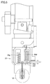
- FIG. 2 and FIG. 3 are schematic views showing the coating member 4 of the coating apparatus shown in FIG.
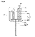
- FIG. 4 is a schematic diagram for explaining the configuration of the coating needle holder in the coating device shown in FIG.
- the above-described application member 4 will be described in more detail with reference to FIGS.
- the two coating members 4 installed in the coating device shown in FIG. 1 have the same configuration.
- the coating member 4 fixed to the Z-axis table 3 shown in FIG. 1 includes a coating needle holder 20 including a coating needle portion 24.
- the application needle portion 24 of the application needle holder 20 includes the application needle 24a and the outer cylinder 24b as described above.
- the outer cylinder 24b is a cylindrical member surrounding the outer periphery of the application needle 24a.
- the outer cylinder 24b is relatively movable with respect to the application needle 24a by the first drive unit 80.
- the application member 4 further includes a second drive unit 40 that moves the application needle holder 20 in the extending direction of the application needle 24a, and a container 21 that holds a liquid material that is a material to be applied.
- the application needle holder 20 is detachably connected to the second drive unit 40.
- the structure for connecting the coating needle holder 20 to the second drive unit 40 can employ any structure.
- the application needle holder 20 mainly includes the application needle part 24, the application needle support plate 20c, the first driving unit 80, and the holder outer shell 20a, as shown in FIG.
- the first drive unit 80 and the coating needle support plate 20c are arranged inside the holder outer shell 20a.
- the application needle portion 24 is arranged in a state where a part thereof protrudes outward from a lower portion of the holder outer shell 20a.
- the root of the coating needle 24a is fixed to the tip of the coating needle support plate 20c.
- the root of the application needle 24a is an end of the application needle 24a located inside the holder outer shell 20a and facing the application needle support plate 20c.
- the tip of the application needle 24a is an end opposite to the root of the application needle 24a.
- the root of the outer cylinder 24b is fixed to the movable plate 20f.
- the root of the outer cylinder 24b is an end located inside the holder outer shell 20a in the outer cylinder 24b and facing the movable plate 20f.
- the root of the outer cylinder 24b is a part of the outer cylinder 24b surrounding the root of the application needle 24a.
- the movable plate 20f is formed with a hole through which the coating needle 24a is inserted at a portion where the outer cylinder 24b is fixed.
- the application needle 24a is disposed inside the outer cylinder 24b through the corresponding hole of the movable plate 20f.
- the first drive section 80 includes the movable plate 20f, an electromagnetic solenoid 20d, a movable shaft 20e, and a spring 20g.
- the movable plate 20f includes a first portion to which one end of the movable shaft 20e is fixed, and a second portion to which one end of the spring 20g is fixed.
- the other end of the spring 20g opposite to the one end fixed to the movable plate 20f is fixed to the application needle support plate 20c.
- the spring 20g urges the movable plate 20f toward the tip of the application needle 24a.
- the other end of the spring 20g may be fixed to the inner wall of the outer shell 20a.
- the movable shaft 20e is movable by an electromagnetic solenoid 20d.
- the electromagnetic solenoid 20d is electrically connected to the coating needle holder side electrode 20b.
- the application needle holder side electrode 20b is connected to the movable part side electrode 46a of the movable part 46 to which the application needle holder 20 is fixed. Electric power is supplied to the electromagnetic solenoid 20 d from outside the coating member 4 via the movable portion side electrode 46 a and the coating needle holder side electrode 20 b.
- a spring 20g and an electromagnetic solenoid 20d are connected to a second surface of the movable plate 20f opposite to the first surface of the outer cylinder 24b. More specifically, the electromagnetic solenoid 20d is connected to the second surface of the movable plate 20f via the movable shaft 20e.
- the spring 20g, the movable shaft 20e, and the electromagnetic solenoid 20d are arranged on the side opposite to the outer cylinder 24b when viewed from the movable plate 20f.
- the application needle 24a is disposed inside the outer cylinder 24b.
- the tip of the coating needle 24a and the outer cylinder 24b which is the end opposite to the root, is located on the opposite side to the spring 20g and the electromagnetic solenoid 20d when viewed from the movable plate 20f.
- the spring 20g and the electromagnetic solenoid 20d are arranged so as to sandwich the coating needle support plate 20c.
- the central axis of the spring 20g and the electromagnetic solenoid 20d is arranged along the extending direction of the application needle 24a. Note that the central axis of the spring 20g means a winding center around which a wire constituting the spring 20g, which is a coil spring, is wound.
- the central axis of the electromagnetic solenoid 20d means a winding center around which a conductive wire constituting the electromagnetic solenoid 20d is wound.
- the outer cylinder 24b can be moved by the electromagnetic solenoid 20d via the movable shaft 20e and the movable plate 20f.
- the electromagnetic solenoid 20d operates to move the movable shaft 20e upward (in a direction away from the tip end side opposite to the root of the coating needle 24a)
- the outer cylinder 24b is moved to the position of the coating needle 24a. It moves relatively to the application needle 24a toward the root side, that is, in the direction approaching the application needle support plate 20c.
- the second drive section 40 includes a servomotor 41, a cam 43, a bearing 44, a cam connecting plate 45, and a movable section 46.
- the servo motor 41 is installed such that the rotation axis extends in a direction along the Z-axis direction shown in FIG. 1, for example.
- a cam 43 is connected to the rotation shaft of the servo motor 41.
- the cam 43 is rotatable about a rotation axis of the servomotor 41.
- the cam 43 includes a central portion connected to the rotation shaft of the servomotor 41, and a flange portion connected to one end of the central portion.
- the upper surface of the flange portion (the surface on the servo motor 41 side) is a cam surface.
- the cam surface is formed in an annular shape along the outer periphery of the center. As shown in FIGS. 2 and 3, the cam surface is formed in a slope shape so that the distance from the bottom surface of the flange portion varies.
- the cam surface has an upper end flat region where the distance from the bottom surface of the flange portion is the largest, and a lower end flat region where the distance from the bottom surface of the flange portion is arranged with a distance from the upper end flat region and A slope portion connecting the upper end flat region and the lower end flat region.
- a bearing 44 is arranged in contact with the cam surface of the cam 43.
- the bearing 44 is disposed in a specific direction (to the right of the servomotor 41) when viewed from the cam 43 as shown in FIGS.
- the bearing 44 keeps contact with the cam surface when the cam 43 rotates due to the rotation of the rotation shaft of the servomotor 41.
- a cam connecting plate 45 is connected to the bearing 44. In the cam connecting plate 45, the other end opposite to the one end connected to the bearing 44 is fixed to the movable portion 46.
- the movable part 46 is connected to an application needle holder storage part.
- the coating needle holder 20 described above is stored in the coating needle holder storage section.
- a first connection member such as a magnet may be arranged on a surface of the application needle holder 20 facing the application needle holder storage unit.
- a second connection member such as a magnet or a magnetic material, which can fix the above-described first connection member on the application needle holder 20 side may be arranged on the application needle holder storage section side.
- a container 21 is arranged below the application needle holder 20.
- the application needle portion 24 is held in the container 21 in a state of being inserted.
- a fixed pin is provided on the movable part 46.
- the other holding pin is installed on the gantry holding the servomotor 41.
- a spring is provided to connect between these two fixing pins. Due to this spring, the movable portion 46 is in a state of receiving a tensile force toward the container 21. Further, the tensile force by the spring acts on the bearing 44 via the movable portion 46 and the cam connecting plate 45. The bearing 44 is kept pressed against the cam surface of the cam 43 by the tensile force of the spring 50.
- the movable section 46 and the application needle holder storage section are connected to a linear guide installed on the gantry.
- the linear guide is arranged to extend in the Z-axis direction. Therefore, the movable part 46 and the application needle holder storage part are movable along the Z-axis direction.
- FIG. 2 shows a state in which the application needle portion 24 is relatively displaced upward in the Z-axis direction
- FIG. 3 shows a state in which the application needle portion 24 is relatively displaced downward in the Z-axis direction.
- FIGS. 5 and 7 are schematic diagrams for explaining the operation of the application needle holder 20 in the application member shown in FIGS. 2 and 3.
- FIG. 6 is an enlarged schematic diagram of a region VI in FIG.
- FIG. 8 is an enlarged schematic diagram of a region VIII in FIG. 5 and 6 show a coating standby state, and FIGS. 7 and 8 show a coating state.
- the outer cylinder 24b stands by while being relatively lowered with respect to the coating needle 24a.
- the distance between the lower end of the electromagnetic solenoid 20d and the movable plate 20f is a distance L1.
- the tip of the application needle 24a is housed in the back of the outer cylinder 24b.
- a part of the liquid material 70 is held between the tip of the outer cylinder 24b and the tip of the application needle 24a and inside the outer cylinder 24b.
- the outer cylinder 24b is relatively raised with respect to the application needle 24a by the operation of the electromagnetic solenoid 20d.
- the distance between the lower end of the magnetic solenoid 20d and the movable plate 20f is a distance L2 smaller than the distance L1 shown in FIG.
- a part of the liquid material 70 held inside the distal end side of the outer cylinder 24b is pushed out and accumulates at the distal end of the application needle 24a.
- the liquid material is supplied to the surface of the processing target material by applying the accumulated liquid material to the surface of the processing target material.
- Such a coating standby state and a coating state are repeatedly performed.
- the tip of the application needle 24a is stored in the container 21 of the liquid material. Thereafter, the outer cylinder 24b is relatively lowered with respect to the application needle 24a by the operation of the electromagnetic solenoid 20d. As a result, as shown in FIGS. 5 and 6, the tip of the application needle 24a is housed inside the outer cylinder 24b, and a part of the liquid material 70 is held again inside the tip of the outer cylinder 24b.
- the tip of the application needle 24a is The liquid material may be stored in the container 21. Also in this case, a part of the liquid material 70 flows into the inside of the distal end side of the outer cylinder 24b in which the distal end of the application needle 24a is stored.
- the actuator for moving the outer cylinder 24b up and down is not limited to the above-described electromagnetic solenoid 20d, but may be any mechanism.
- any actuator such as an air cylinder or an electric cylinder, or a reciprocating mechanism such as a cam mechanism or a crank mechanism may be used as an actuator for moving the outer cylinder 24b relative to the application needle 24a.
- the electromagnetic solenoid 20d is used as the actuator, effects such as a reduction in the size and weight of the coating needle holder 20 and a reduction in the operation time of the outer cylinder 24b can be obtained.
- FIG. 9 is a schematic diagram for explaining a coating method as a comparative example.
- FIG. 10 is a schematic diagram for explaining a coating method according to the present embodiment. The coating method according to the present embodiment shown in FIG. 10 will be described in comparison with the coating method as a comparative example shown in FIG. 9 and 10 show a case where another liquid material is applied to the liquid material 75 previously applied to the surface of the material 5 to be processed.
- the width of the distal end is gradually narrowed, and the application needle 124 having a flat distal end surface is used.
- the amount of the liquid material 70 adhering to the flat tip surface of the application needle 124 is substantially determined by the viscosity of the liquid material 70. Therefore, it has been difficult to arbitrarily control the amount of the liquid material 70 attached to the front end surface. Generally, the amount of the liquid material 70 attached to the tip end surface of the application needle 124 is very small.
- the liquid material 70 is applied to the surface of the processing target material 5 by using such an application needle 124 so as to overlap the liquid material 75 previously applied.
- a mixed liquid material 77 in which the liquid material 75 previously applied and the liquid material 70 attached to the tip of the application needle 124 are mixed together also adheres to the tip side.
- the adhesive hardens at the tip of the application needle 124 and adversely affects subsequent application.
- the liquid materials 70 and 75 are not a two-liquid adhesive, if the liquid material 70 attached to the tip of the application needle 124 is contaminated with the liquid material 75 applied earlier, the application needle The liquid material 70 held in the container of the coating material containing 124 is also contaminated.
- the coating method according to the present embodiment shown in FIG. 10 first, as shown in FIG. A part 70a of the liquid material is held in a space between the one end 26 and the tip 25 of the application needle 24a. Thereafter, the outer cylinder 24b is raised relatively to the application needle 24a. As a result, as shown in FIG. 10B, the liquid material 70a (see FIG. 10A) is extruded from the space inside the first end 26 of the outer cylinder 24b to the outside of the first end 26, and the liquid droplets are dropped. 71.
- the tip 25 of the application needle 24a may be located on the same plane as the first end 26 of the outer cylinder 24b.
- the tip 25 of the application needle 24a may be arranged inside the first end 26 of the outer cylinder 24b, or may be arranged outside the first end 26. Since the liquid material 70a to be the droplet 71 is held inside the outer cylinder 24b in this manner, the volume of the droplet 71 is smaller than that of the liquid material 70 attached to the tip of the application needle 124 in the comparative example shown in FIG. Be larger than volume.
- the application needle 24a and the outer cylinder 24b are relatively brought closer to the processing target material 5.
- the application needle 24 a and the outer cylinder 24 b are moved in the direction indicated by the arrow toward the material 5 to be processed from the configuration of the application member 4.
- the processing target material 5 may be moved toward the application needle 24a and the outer cylinder 24b.
- the droplet 71 held on the tip side of the coating needle 24a and the outer cylinder 24b comes into contact with the liquid material 75 on the surface of the processing target material 5.
- the lower end of the droplet 71 is brought into contact with the liquid material 75 on the surface of the processing target material 5.
- the application needle 24a and the outer cylinder 24b are moved in the direction of the arrow from the processing target material 5 side.
- the liquid material 75 previously applied to the processing target material 5 is used as the first liquid material of the two-component adhesive, and the liquid material droplet 71 to be applied later is used as the second liquid material. It may be used as the material of the second liquid of the adhesive.
- the processing target material 5 may be a solid member having a flat plate or a curved surface, but may be a liquid or gel member, and has a surface on which the liquid material 75 can be disposed. Anything is good.
- the tip 25 of the application needle 24a may be contaminated by the first liquid. Performance can be reduced. As a result, stable application becomes possible.
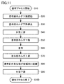
- FIG. 11 is a flowchart of the coating method according to the present embodiment. The coating method according to the present embodiment will be described with reference to FIG. 11 and FIGS. 5 to 10 as appropriate.
- a coating process is started (S10). Specifically, for example, control of each device of the coating apparatus is started by the control computer 10.
- the X-axis table 1, the Y-axis table 2, the Z-axis table 3, and the like are controlled so that, for example, the application member 4 is disposed at a position facing the processing target material 5.
- the tip 25 of the application needle 24a of the application needle holder 20 is located inside the outer cylinder 24b.
- the distal end of the outer cylinder 24b is in a state of being disposed inside the container 21.
- a liquid material 70a is disposed inside the distal end side of the outer cylinder 24b.
- the lowering of the application needle holder is started (S20). Specifically, the application needle holder 20 is moved to the container 21 by the second drive unit 40. As a result, both the outer cylinder 24b and the application needle 24a protrude from the bottom surface of the container 21. At this time, the tip 25 of the application needle 24a is retracted from the first end 26 of the outer cylinder 24b as shown in FIG. A liquid material 70a is held between the first end 26 of the outer cylinder 24b and the tip 25 of the application needle 24a.
- the outer cylinder 24b is raised (S40). Specifically, as described with reference to FIGS. 7 and 8, the electromagnetic solenoid 20d is driven to pull up the outer cylinder 24b to the root side of the outer cylinder 24b. As a result, as shown in FIG. 10B, the tip 25 of the application needle 24a relatively moves to the first end 26 side of the outer cylinder 24b, and the liquid droplets fall below the first end 26 of the outer cylinder 24b. 71 are formed.
- the lowering of the application needle holder is started again (S50).
- the application needle 24a holding the droplet 71 approaches the processing target material 5.
- the application step (S60) of supplying the liquid material so as to be applied to the surface of the processing target material 5 is performed.
- the distance between one of the tip 25 of the coating needle 24a or the first end 26 of the outer cylinder 24b close to the processing target material 5 and the surface of the processing target material 5 is: It is preferable that the diameter be greater than zero and less than the diameter of the droplet 71.
- the liquid material can be applied to the surface of the descending target material 55 without the coating needle 24a or the outer cylinder 24b coming into direct contact with the processing target material 5.
- the diameter of the droplet 71 can be determined in consideration of the viscosity of the liquid material forming the droplet 71 and the like. Further, the diameter can be adjusted by changing the distance by which the tip 25 of the application needle 24a retreats inside the outer cylinder 24b.
- the lifting of the application needle holder is stopped (S80).
- the position of the first end 26 of the outer cylinder 24b is set such that the first end 26 is not exposed to the outside of the container 21 even when the first end 26 is lowered relative to the application needle 24a inside the container 21. It is preferable that the liquid material 70 is kept in the liquid material 70 held in the container 21.
- the outer cylinder 24b is lowered relatively to the application needle 24a (S90).
- the distal end 25 of the application needle 24a is retracted from the first end 26 of the outer cylinder 24b.
- a part of the liquid material 70 inside the container 21 is arranged inside the outer cylinder 24b on the first end 26 side.
- FIG. 12 is a flowchart of a modification of the coating method according to the present embodiment. A modification of the coating method according to the present embodiment will be described with reference to FIG. 12 and FIGS. 5 to 11 as appropriate.
- steps (S10) to (S30) are performed in the same manner as the coating method shown in FIG. Thereafter, as shown in FIG. 12, the outer cylinder 24b is raised while lowering the application needle holder 20 at a low speed (S140). In this step (S140), the application needle holder 20 is moved to the container 21 by the second driving unit 40. The lowering speed of the application needle holder 20 in this step (S140) is lower than the lowering speed of the application needle holder 20 in steps (S20) to (S30). At the same time, the outer cylinder 24b rises relatively to the application needle 24a. Specifically, similarly to the step (S40) of FIG. 11, the electromagnetic solenoid 20d described with reference to FIGS.
- the timing of starting the lowering of the coating needle holder 20 and the timing of starting the raising of the outer cylinder 24b may be the same.
- the start timing may be later or earlier.
- the application needle holder 20 continues to descend while the droplet 71 is formed as described above, the application needle 24 a holding the droplet 71 approaches the processing target material 5. Then, when the droplet 71 comes into contact with the surface of the processing target material 5, at least a part of the droplet 71 adheres to the surface of the processing target material 5. Thus, the application step (S60) of applying the liquid material to the surface of the processing target material 5 is performed.
- the application step (S60) and steps (S70) to (S100) are basically the same as steps (S60) to (S100) shown in FIG.
- the application member 4 includes an application needle 24a for supplying a liquid to a material to be processed, an outer cylinder 24b, a first drive unit 80, and a second drive unit 40.
- the outer cylinder 24b surrounds the outer periphery of the application needle 24a and includes a first end 26 located on a side closer to the tip of the application needle 24a.
- the first drive unit 80 relatively moves the outer cylinder 24b with respect to the application needle 24a in a first direction that is the extending direction of the application needle 24a.
- the second drive section 40 moves the application needle 24a and the outer cylinder 24b in the first direction.
- the first driving unit 80 performs a first state in which the tip 25 of the application needle 24a is retracted into the outer cylinder 24b from the first end 26 of the outer cylinder 24b (see FIGS. 6 and 10A).
- the second state (see FIGS. 8, 10B, 10C, and 10D) in which the tip 25 of the needle 24a has moved from the first state to the first end 26 of the outer cylinder 24b. It is configured to switch.
- the application needle holder 20 includes an application needle 24a for applying a liquid to a material to be processed, an outer cylinder 24b, and a first driving unit 80.
- the outer cylinder 24b surrounds the outer periphery of the application needle 24a and includes a first end 26 located on a side closer to the tip 25 of the application needle 24a.
- the first drive unit 80 relatively moves the outer cylinder 24b with respect to the application needle 24a in a first direction that is the extending direction of the application needle 24a.
- the first drive unit 80 includes a first state in which the tip 25 of the application needle 24a is retracted into the outer cylinder 24b from the first end 26 of the outer cylinder 24b, and a state in which the tip 25 of the application needle 24a is out of the first state. It is configured to switch between the second state in which the cylinder 24b has moved to the first end 26 side.
- the coating needle 24a is provided with the outer cylinder 24b. Further, in the container 21 which is a coating material container, the distal end 25 of the coating needle 24a is in a first state in which the distal end 25 is stored more deeply than the first end 26 which is the distal end of the outer cylinder 24b.
- the liquid material 70a to be applied can be stored in a portion on the front side of the front end 25.
- the outer cylinder 24b is pulled up by the electromagnetic solenoid 20d to be in the second state, and the stored liquid material 70a is removed.
- the first driving unit 80 includes an electromagnetic solenoid 20d.
- the electromagnetic solenoid 20d By using the electromagnetic solenoid 20d, the application member 4 and the application needle holder 20 can be reduced in size and weight. Further, as compared with the case where another mechanical actuator is used, the operation speed of raising and lowering the outer cylinder 24b can be increased, and the time required for moving the outer cylinder 24b can be reduced.
- the coating apparatus includes the coating member 4 or the coating needle holder 20 and the Y-axis table 2 as a holding table.
- the Y-axis table 2 as a holding table holds the processing target material 5 to which the liquid material 70 is applied by the application needle 24a.
- the application member 4 or the application needle holder 20 that can apply the liquid material 70 stably, the application of the liquid material such as the two-component adhesive to the processing target material 5 by the application needle 24a. Can be performed stably.
- the coating device includes the container 21 that holds the liquid material 70. Also, from a different point of view, the coating device includes a container 21 for holding the liquid material 70 and a second drive unit 40 in addition to the coating needle holder 20.
- the second drive section 40 moves the application needle 24a and the outer cylinder 24b in the first direction.
- the container 21 is arranged so as to face the processing target material 5 held on the Y-axis table 2 as a holding table.
- the second driving unit 40 of the coating member 4 includes a third state in which the tip 25 of the coating needle 24a and the first end 26 of the outer tube 24b are located inside the container 21 (see FIGS. 2, 5, and 6).
- the tip 25 of the coating needle 24a and the first end 26 of the outer cylinder 24b are configured to switch between a fourth state (see FIGS. 3, 4, 7, and 8) in which the outer end is located outside the container 21.
- the first driving unit 80 moves the outer cylinder 24b relative to the application needle 24a such that the first driving unit 80 is in the first state in the third state as shown in FIG. 6 and is in the second state in the fourth state as shown in FIG. Move to That is, the coating apparatus is configured such that the tip 25 of the coating needle 24a and the first end 26 of the outer cylinder 24b penetrate the container 21 to apply the liquid material to the processing target material 5.
- the liquid material 70a can be held inside the container 21 on the first end 26 side of the outer cylinder 24b as shown in FIG. 10A, while FIG. As shown in FIG. 10C, a droplet 71 made of a liquid material is formed outside the first end 26 of the outer cylinder 24b, and the droplet 71 can be brought into contact with the surface of the processing target material 5. As a result, a liquid material such as a two-component adhesive can be stably applied.
- the coating member 4 is set to the first state, and the liquid material 70a is placed in the inner region of the outer cylinder 24b located between the tip 25 of the coating needle 24a and the first end 26 of the outer cylinder 24b.
- Step (S90) in FIGS. 11 and 12 the step of causing at least a part 71 of the liquid material to project outside the first end 26 of the outer cylinder 24b by changing the coating member 4 from the first state to the second state.
- S40 or the steps (S140) and (S150) of FIG. 12 are performed.
- a step of bringing at least a part 71 see FIG.
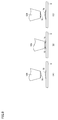
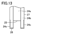
- FIG. 13 is a schematic diagram for explaining a first modification of the application member and the application needle holder according to the present embodiment.
- the first modified example of the application member and the application needle holder shown in FIG. 13 basically has the same configuration as the application member 4 and the application needle holder 20 shown in FIGS.
- the configuration of the first end 26 and the portion of the side surface connected to the first end 26 is different from the coating member and the coating needle holder 20 shown in FIGS. That is, in the outer cylinder 24b shown in FIG. 13, the lyophobic treatment portion 24c is formed on the first end 26 and the outer peripheral side surface portion 27 continuous with the first end 26.
- the lyophobic treatment section 24c is, for example, a region to which a lyophobic treatment agent is applied.
- the liquid-repellent agent for example, a fluorine-based agent can be used.
- the liquid-repellent treatment part 24c By forming the liquid-repellent treatment part 24c in this way, when forming a droplet 71 made of a liquid material at the tip 25 of the application needle 24a as shown in FIG. There is a problem that the liquid material remains on the outer peripheral side surface portion 27 and the first end 26 of the 24b and the size of the formed droplet 71 is reduced, or the shape of the droplet 71 is distorted from a spherical shape. Generation can be suppressed. For this reason, since the liquid material can be stably applied to the processing target material 5 from the tip 25 of the application needle 24a at the time of application, the possibility that the contaminated liquid material adheres to the application needle 24a after the application process can be reduced.
- FIG. 14 shows a first state in which the tip 25 of the application needle 24a is retracted inside the outer cylinder 24b from the first end 26 of the outer cylinder 24b.
- FIG. 15 shows a second state in which the tip 25 of the application needle 24a has moved from the first state to the first end 26 side of the outer cylinder 24b.
- the second modification of the coating member and the coating needle holder shown in FIGS. 14 and 15 basically has the same configuration as the coating member 4 and the coating needle holder 20 shown in FIGS.
- the configuration of the distal end of the outer cylinder 24b is different from the coating member and the coating needle holder 20 shown in FIGS. That is, in the coating member 4 and the coating needle holder 20 shown in FIGS. 14 and 15, the end of the outer cylinder 24b on the side where the first end 26 is formed is a tapered portion 24d having a tapered shape.
- the tapered portion 24d has a tapered shape such that the outer diameter increases as the distance from the first end 26 increases. Further, the thickness of the tapered portion 24d is gradually reduced toward the tip of the outer cylinder 24b.
- the tapered portion 24d has a surface extending so as to be inclined with respect to the direction in which the outer cylinder 24b extends.
- FIG. 16 and FIG. 17 are schematic diagrams for explaining a third modification of the application member and the application needle holder according to the present embodiment.
- FIG. 16 shows a first state in which the tip 25 of the application needle 24a is retracted from the first end 26 of the outer cylinder 24b into the outer cylinder 24b.
- FIG. 17 shows a second state in which the tip 25 of the application needle 24a has moved from the first state to the first end 26 side of the outer cylinder 24b.
- the second modification of the coating member and the coating needle holder shown in FIGS. 16 and 17 basically has the same configuration as the coating member 4 and the coating needle holder 20 shown in FIGS. 14 and 15,
- the configuration of the distal end of the outer cylinder 24b is different from that of the application member and the application needle holder 20 shown in FIGS. That is, in the coating member 4 and the coating needle holder 20 shown in FIGS. 16 and 17, the liquid-repellent treatment portion 24c is formed on the surface of the tapered portion 24d at the tip of the outer cylinder 24b.
- the liquid-repellent treatment part 24c extends from the tapered part 24d to a side surface of the outer cylinder 24b connected to the tapered part 24d.
- liquid-repellent portion 24c may be formed only in the tapered portion 24d.
- the effects of the application member 4 and the application needle holder 20 shown in FIGS. 14 and 15 the effects of the application member 4 and the application needle holder 20 shown in FIG.
- the supply of the liquid material to the material to be processed is performed by the coating apparatus in FIG.
- the application mechanism provided in the application device includes, for example, two application members 4 as the plurality of application members 4.
- One of the two application members 4 includes a first application needle holder.
- the other application member 4 of the two application members 4 includes a second application needle holder.
- the coating device includes the first coating needle holder and the second coating needle holder as the plurality of coating needle holders. The reason for having the first coating needle holder and the second coating needle holder is to supply a plurality of different liquid materials with a single coating device.
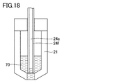
- FIG. 18 is an enlarged schematic view of the same area as the area shown in FIG. 6 in the fourth modified example of the present embodiment.
- the application needle section 24 (see FIG. 4) included in the second application needle holder has an application needle 24e and an outer cylinder 24f.
- the application needle 24e has the same configuration as the application needle 24a in FIG.
- the outer cylinder 24f has the same configuration as the outer cylinder 24b of FIG.
- the second application needle holder has the same structural features as those of the application needle holder in FIG. 6 described above.
- the second application needle holder may have the same structural features as those of any of the above-described application needle holders in FIGS.
- the second applicator needle holder has the same structural features as any of the applicator needle holders in each of the above examples of the present embodiment.
- the application needle 24e included in the application needle section 24 can supply the liquid material 70 to the processing target material by dropping the liquid material 70 from the tip of the application needle 24e.
- the application needle 24e drops the liquid material 70 in a non-contact state with the processing target material from above the processing target material, thereby supplying the liquid material 70 dropwise to the processing target material.
- the present modified example has a different feature from the above-described respective examples in which the liquid material is applied and supplied by lowering the application needle until the droplet comes in contact with the processing target material.
- the first application needle holder may also have the same structural features as any of the application needle holders of the examples of the present embodiment described above. That is, the first applicator needle holder may have the same structural features as those of the applicator needle holder of FIG. 18 or may have the same configuration as the applicator needle holder of any of FIGS. 13 to 17 described above. It may have features. Regarding the first application needle holder as well, the application needle section 24 included therein may have an application needle 24e for dropping the liquid material. Also in the fourth modified example, the features of the coating device in each of the above examples may be appropriately combined.
- FIG. 19 is a flowchart of a liquid material supply method characteristic of the fourth modification.
- the supply method PB of the liquid material characteristic of the fourth modification is roughly the same as the application method shown in FIG.
- a dropping step (S260) is performed instead of the coating step (S60) in FIG.
- FIG. 19 differs from FIG. 11 in this point.
- the supply method PB is basically the same as the application method PA in FIG.
- FIG. 20 is a schematic diagram for explaining a liquid material supply method that is characteristic of the fourth modification.
- FIG. 20A for example, the configuration shown in FIG. 18, that is, an application needle holder having an application needle 24e and an outer cylinder 24f is used.
- an application needle holder having any of the configurations shown in FIGS. 13 to 17 may be used.
- the tip 25 of the application needle 24e is retracted from the first end 26 of the outer cylinder 24f, as in FIG. 10A.
- the amount of retreat of the leading end 25 with respect to the first end 26 is larger than that in FIG. In this way, a larger amount of the liquid material 70a can be held between the first end 26 of the outer cylinder 24f and the tip 25 of the application needle 24e.
- FIG. 20A corresponds to steps (S10) to (S30) in FIG.
- FIG. 20B corresponds to the step (S40) in FIG.
- the droplet 71 may be larger than the droplet shown in FIG.
- the application needle holder is lowered again (S50).
- the droplet 71 is larger than the droplet shown in FIG.
- the droplet 71 is removed from the tip of the coating needle 24e. And fall.
- the droplet 71 is dropped on the surface of the processing target material 5 or on the liquid material 75 that has been supplied earlier to the surface.
- FIG. 20C corresponds to steps (S50) to (S260) in FIG.
- FIG. 21 is a flowchart of a coating method of a comparative example.
- the coating method is attached to a coating needle holder having an arbitrary configuration that does not have the configuration of FIG. 6 or FIGS.
- An application needle is used.
- an application needle not attached to such an application needle holder may be used.
- the application needle 124 in FIG. 9A descends toward the processing target material 5 as shown in FIG. 9B (S350).
- the liquid material 70 attached to the application needle 124 comes into contact with the surface of the processing target material 5 or the liquid material 75 previously applied to the surface. Thereby, the liquid material 70 is applied on the surface of the processing target material 5 or the surface of the liquid material 75 (S360).
- the application needle 124 is raised (S370), and the application process ends.
- FIG. 22 is a flowchart schematically showing a first example of a method for applying a liquid material in a fourth modification of the present embodiment.
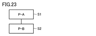
- FIG. 23 is a flowchart schematically showing a second example of the method for applying a liquid material in the fourth modification of the present embodiment.
- the coating method of the fourth modification includes a first coating step (S1) and a second coating step (S2).
- S1 a first liquid material is applied to a material to be processed.
- S2 after the first application step (S1), a second liquid material different from the first liquid material is applied to the processing target material.
- applying the liquid material to the material to be treated includes applying or dripping the liquid material so as to overlap the liquid material already supplied on the material to be treated.
- the coating method PC of the comparative example in the first coating step (S1), the coating method PC of the comparative example (see FIGS. 21 and 9) is used.
- the second coating step (S2) the supply method PB of the fourth modified example (see FIGS. 18, 19, and 20) is used.
- the coating method PA of each of the above examples see FIGS. 11 and 10) is used.
- the second application step (S2) in the second example of FIG. 23 the supply method PB of the fourth modification (see FIGS. 19 and 20) is used.
- the supply method PB using the second coating needle holder shown in FIGS. 18 to 20 is applied. That is, in the second application step (S2), the supply of the liquid material 70 or the like by dropping is performed.
- the liquid material is supplied by the application method PA using the first application needle holder having the configuration of FIG. 6 or FIGS. You may.
- the first coating step (S1) similarly to the second coating step (S2), the liquid material is supplied by the supply method PB using the coating needle holder having the configuration shown in FIGS. Is also good.
- an application needle (application needle holder) as in the comparative example of FIG. 9 is used as in the example of FIG. 22, and the application of the liquid material by the application method PC is performed. You may.
- the coating device according to the fourth modified example is a coating device including a first coating needle holder and a second coating needle holder as a plurality of coating needle holders.
- the second application needle holder has the same configuration as that of FIG. 6 and any of FIGS. 13 to 18 (for example, FIG. 18).
- the second application needle holder includes an application needle 24e capable of supplying the liquid material 70a to the processing target material 5 by dropping the liquid material 70a (see FIG. 20) as the droplet 71 from the distal end 25.
- the liquid material 75 when the liquid material 75 is already applied onto the processing target material 5 and the liquid material 70a as another material is supplied, the liquid is supplied to the application needle 24e included in the second application needle holder.
- the attachment of the material 75 is suppressed.
- the liquid material 70a is supplied by being dropped onto the liquid material 75 in a state where the liquid material 70a and the application needle 24e are not in contact with the liquid material 75.
- the first coating needle holder may have the same configuration as any of FIGS. 6 and 13 to 18 similarly to the second coating needle holder. That is, the first application needle holder may also include the application needle 24e capable of supplying the liquid material 70a to the processing target material 5 by dropping the liquid material 70a (see FIG. 20) from the tip 25, for example. With this configuration, it is also possible to suppress the contamination in the container 21 caused by the attachment of another liquid material to the application needle included in the first application needle holder.
- the application method according to the fourth modified example includes a first application step (S1) of applying the first liquid material 75 to the processing target material 5, and a coating method for the processing target material 5 after the first coating step (S1).
- a second application step (S2) of applying the second liquid material 70a In the second coating step (S2), a second coating needle holder (for example, as shown in FIG. 18) having the same configuration as that shown in FIGS. 6 and 13 to 18 is used.
- the second liquid material 70a is supplied to the processing target material 5 by dropping the second liquid material 70a from the tip 25 of the application needle 24e.
- the coating method according to the fourth modification is a coating method using a first coating needle holder and a second coating needle holder, and includes a first coating step (S1). And a second coating step (S2).
- the first application step (S1) the first liquid material 75 is applied to the processing target material 5 using the first application needle holder.
- the second application step (S2) the second liquid material 70a is applied to the processing target material 5 after the first application step (S1).
- a second coating needle holder is used.
- the second application needle holder is provided with an application needle 24e for supplying the second liquid material 70a to the processing target material 5, and a second application needle holder that surrounds the outer periphery of the application needle 24e and is located closer to the tip 25 of the application needle 24e. And an outer cylinder 24f including one end 26.
- the second liquid material 70a is supplied to the processing target material 5 by dropping the second liquid material 70a from the tip 25 of the coating needle 24e.
- the tip 25 of the coating needle 24e in the second coating needle holder is positioned inside the outer cylinder 24f from the first end 26 of the outer cylinder 24f. Holding the second liquid material 70a in the internal region of the outer cylinder 24f located between the tip 25 of the coating needle 24e and the first end 26 of the outer cylinder 24f in the first state (FIG. Step 19 (S90)) is performed.
- step (S40) in FIG. 19 A step of projecting at least a portion of the second liquid material 70a outside the first end 26 of 24f (step (S40) in FIG. 19) is performed. Further, a step (step (S260) in FIG. 19) of dropping the droplet 71, which is at least a part of the second liquid material 70a protruding outside the first end 26, onto the processing target material 5 is performed.
- the liquid material 75 when the liquid material 75 is already applied onto the processing target material 5 and the liquid material 70a as another material is supplied, the liquid is supplied to the application needle 24e included in the second application needle holder.
- the attachment of the material 75 is suppressed.
- the liquid material 70a and the application needle 24e are supplied by dropping the droplet 71 of the liquid material 70a onto the liquid material 75 in a state where the liquid material 75 is not in contact with the liquid material 75. Therefore, contamination of the container 21 due to, for example, the liquid material 75 that is a material other than the liquid material 70a originally stored in the container 21 that is the application material container can be suppressed.
- a first coating needle holder or a second coating needle holder having any one of the configurations shown in FIG. 6 or FIGS. May be used.
- the coating needle of the comparative example in FIG. 9 may be used.
- the first liquid material 75 is supplied to the processing target material 5 from the tip of the application needle.
- the application member used in the first application step (S1) can increase the degree of freedom of selection.
- the number of application members 4 included in the application device in FIG. 1 is not limited to two, and may be three or more.
- all but one of the plurality of three or more coating members 4 include, as a second coating needle holder, a coating needle having, for example, a configuration as shown in FIG.
- the material is supplied.
- the other one may have, for example, a configuration as shown in FIG. 18 as the first application needle holder, or a configuration having any of the configurations shown in FIGS. 6, 13 to 17. Is also good.
- the application needle of the first application needle holder may have the configuration of the comparative example in FIG.
- the first liquid material 75 is supplied to the processing target material 5 from the tip of the application needle by the application needle of the first application needle holder (see FIG. 20). Thereafter, that is, in the second step and thereafter (including the third step, the fourth step, and the like), the second application needle holder is used.
- the liquid material 72 is supplied to the processing target material 5 by dropping the liquid material 70a as the droplet 71 from the tip end 25 of the application needle 24e as in the dropping process PB in FIGS. 19 and 20.
- the second application needle holder preferably includes the application needle 24e to which the droplet 71 can be dropped.
Landscapes
- Coating Apparatus (AREA)
- Application Of Or Painting With Fluid Materials (AREA)
Abstract
Provided are a coating needle holder, a coating member, a coating device, and a coating method, whereby coating application or other supply of a liquid material can be stably performed using a coating needle. A coating needle holder (20) is provided with a coating needle (24a) for supplying a liquid to a treatment object member (5), an outer cylinder (24b), and a first drive unit (80). The outer cylinder (24b) surrounds the outer periphery of the coating needle (24a) and includes a first end (26) positioned on the side close to the distal end (25) of the coating needle (24a). The first drive unit (80) causes the outer cylinder (24b) to move relative to the coating needle (24a) in a first direction which is the direction in which the coating needle (24a) extends. The first drive unit (80) is configured so as to switch between a first state in which the distal end (25) of the coating needle (24a) is retracted into the outer cylinder (24b) from the first end (26) of the outer cylinder (24b), and a second state in which the distal end (25) of the coating needle (24a) is moved further toward the first end (26) of the outer cylinder (24b) than in the first state.
Description
この発明は、塗布針ホルダ、塗布部材、塗布装置および塗布方法に関し、より特定的には、塗布針を用いて処理対象材に液体材料を塗布するための塗布針ホルダ、塗布部材、塗布装置および塗布方法に関する。
The present invention relates to a coating needle holder, a coating member, a coating device, and a coating method, and more specifically, to a coating needle holder, a coating member, a coating device, and a coating needle for coating a liquid material on a material to be processed using a coating needle. Related to the application method.
従来、機械装置の製造プロセスにおいて、微小な光学部品などを接着剤を用いて固定する工程が知られている。このような工程では、比較的粘度の高い接着剤を微小に塗布する要求が多くある。
Conventionally, in a manufacturing process of a mechanical device, a step of fixing a minute optical component or the like using an adhesive is known. In such a process, there are many demands for applying a relatively high-viscosity adhesive minutely.
接着剤の一般的な塗布方法としては、ディスペンサ方式、インクジェット方式などが挙げられる。しかし、ディスペンサ方式では、塗布後の直径がФ100μm以下となるような接着剤の微小量の塗布は難しい。また、インクジェット方式では、粘度100mPa・s以上の接着剤の塗布は難しい。
一般 General methods of applying the adhesive include a dispenser method and an ink jet method. However, in the dispenser method, it is difficult to apply a very small amount of adhesive such that the diameter after application is less than 100 μm. In the ink jet method, it is difficult to apply an adhesive having a viscosity of 100 mPa · s or more.
上記のような高粘度の接着剤の微小量の塗布を実現する塗布方式の1つとして、特開2015-112576号公報に記載のような塗布針を用いて塗布する方式がある。特開2015-112576号公報では、塗布する液体を保持した容器を貫通するとともに、先端部が容器から出入りできるように移動可能に構成された塗布針を備えた塗布装置が開示されている。
塗布 As one of the application methods for realizing the application of a minute amount of the high-viscosity adhesive as described above, there is a method of applying using an application needle as described in JP-A-2015-112576. Japanese Patent Application Laid-Open No. 2015-112576 discloses a coating apparatus provided with a coating needle that penetrates a container holding a liquid to be coated and that is movable so that a tip portion can move in and out of the container.
ここで、上記特開2015-112576号公報に開示された塗布針を備える塗布装置を用いて、たとえば2液性接着剤を処理対象材に塗布する場合、塗布針を含む塗布部材を2台用いて、それぞれの接着剤を塗布することになる。具体的には、一方の塗布部材を用いて1液目の接着剤を塗布し、塗布された1液目の接着剤上に他方の塗布部材を用いて2液目の接着剤を塗布する。
Here, in the case of applying a two-component adhesive to a material to be treated, for example, using a coating device having a coating needle disclosed in JP-A-2015-112576, two coating members including the coating needle are used. Then, each adhesive is applied. Specifically, the first liquid adhesive is applied using one application member, and the second liquid adhesive is applied on the applied first liquid adhesive using the other application member.
この時、他方の塗布部材における塗布針の先端に付着した2液目の接着剤を全て1液目の接着剤の上に滴下できる訳ではない。すなわち、他方の塗布部材における塗布針先端に1液目の接着剤と接触混合した2液目の接着剤が残存する。そして、他方の塗布部材の塗布針先端において1液目の接着剤と混合した2液目の接着剤が硬化すると、塗布針先端が硬化した接着剤により太くなる。この結果、他方の塗布部材の塗布針先端に付着する2液目の接着剤の量が増え、結果的に2液目の接着剤の塗布量が徐々に多くなる。さらに、塗布針の先端が太くなり過ぎると、塗布する液体である2液目の接着剤を保持した容器に当該塗布針を収納できなくなる。このように、従来の塗布装置では、塗布針の先端に塗布する液体が残存することにより液体の塗布を安定して行えなくなる場合があった。
At this time, it is not always possible to drop all of the second liquid adhesive adhering to the tip of the coating needle on the other coating member onto the first liquid adhesive. That is, the second liquid adhesive mixed in contact with the first liquid adhesive remains at the tip of the coating needle of the other coating member. When the second liquid adhesive mixed with the first liquid adhesive hardens at the tip of the application needle of the other application member, the tip of the application needle becomes thicker due to the hardened adhesive. As a result, the amount of the second liquid adhesive adhered to the tip of the application needle of the other application member increases, and as a result, the amount of the second liquid adhesive applied gradually increases. Furthermore, if the tip of the application needle becomes too thick, the application needle cannot be stored in a container holding the second liquid adhesive that is the liquid to be applied. As described above, in the conventional coating apparatus, there is a case where the liquid cannot be stably applied because the liquid to be applied remains at the tip of the application needle.
この発明は、上記のような課題を解決するためになされたものであり、本発明の目的は塗布針を用いて液体材料の塗布などの供給を安定して実施できる塗布針ホルダ、塗布部材、塗布装置および塗布方法を提供することである。
The present invention has been made to solve the above-described problems, and an object of the present invention is to provide a coating needle holder, a coating member, and a coating material that can stably perform supply of a liquid material using a coating needle. An object of the present invention is to provide a coating apparatus and a coating method.
本開示に従った塗布針ホルダは、処理対象材に液体材料を供給するための塗布針と、外筒と、第1駆動部とを備える。外筒は、塗布針の外周を囲み、塗布針の先端に近い側に位置する第1端を含む。第1駆動部は、塗布針の延在方向である第1方向において、塗布針に対して外筒を相対的に移動させる。第1駆動部は、塗布針の先端が外筒の第1端より外筒の内部に後退している第1状態と、塗布針の先端が第1状態より外筒の第1端側に移動した第2状態とを切替えるように構成されている。
The coating needle holder according to the present disclosure includes a coating needle for supplying a liquid material to a material to be processed, an outer cylinder, and a first driving unit. The outer cylinder surrounds the outer periphery of the application needle and includes a first end located closer to the tip of the application needle. The first drive unit moves the outer cylinder relative to the application needle in a first direction that is the direction in which the application needle extends. The first drive unit is configured to move the tip of the application needle from the first state to the first end of the outer cylinder in a first state in which the tip of the application needle is retracted into the outer cylinder from the first end of the outer cylinder. The second state is switched.
本開示に従った塗布装置は、上記塗布針ホルダと、保持台とを備える。保持台は、塗布針により液体材料を塗布される処理対象材を保持する。
塗布 A coating device according to the present disclosure includes the coating needle holder and a holding table. The holding table holds a processing target material to which the liquid material is applied by the application needle.
本開示に従った塗布方法は、第1の塗布針ホルダと第2の塗布針ホルダとを用いた塗布方法であって、第1の塗布工程と第2の塗布工程とを備える。第1の塗布工程では、第1の塗布針ホルダを用いて、処理対象材に第1の液体材料を塗布する。第2の塗布工程では、第1の塗布工程の後に、処理対象材に第2の液体材料を塗布する。第2の塗布工程においては、第2の塗布針ホルダが用いられる。第2の塗布針ホルダは、処理対象材に第2の液体材料を供給するための塗布針と、塗布針の外周を囲み、塗布針の先端に近い側に位置する第1端を含む外筒とを含む。第2の塗布工程においては、塗布針の先端から第2の液体材料を滴下することにより処理対象材に第2の液体材料が供給される。
塗布 A coating method according to the present disclosure is a coating method using a first coating needle holder and a second coating needle holder, and includes a first coating step and a second coating step. In the first application step, the first liquid material is applied to the processing target material using the first application needle holder. In the second application step, a second liquid material is applied to the processing target material after the first application step. In the second coating step, a second coating needle holder is used. The second application needle holder includes an application needle for supplying a second liquid material to the material to be processed, and an outer cylinder surrounding the outer periphery of the application needle and including a first end located closer to the tip of the application needle. And In the second coating step, the second liquid material is supplied to the material to be processed by dropping the second liquid material from the tip of the coating needle.
本開示に従った塗布部材は、上記塗布針ホルダと、第2駆動部とを備える。第2駆動部は、塗布針および外筒を第1方向に移動させる。
塗布 A coating member according to the present disclosure includes the coating needle holder and a second driving unit. The second drive moves the application needle and the outer cylinder in the first direction.
本開示に従った塗布部材は、処理対象材に液体材料を供給するための塗布針と、外筒と、第1駆動部と、第2駆動部とを備える。外筒は、塗布針の外周を囲み、塗布針の先端に近い側に位置する第1端を含む。第1駆動部は、塗布針の延在方向である第1方向において、塗布針に対して外筒を相対的に移動させる。第2駆動部は、塗布針および外筒を第1方向に移動させる。第1駆動部は、塗布針の先端が外筒の第1端より外筒の内部に後退している第1状態と、塗布針の先端が第1状態より外筒の第1端側に移動した第2状態とを切替えるように構成されている。
塗布 The application member according to the present disclosure includes an application needle for supplying a liquid material to a material to be processed, an outer cylinder, a first drive unit, and a second drive unit. The outer cylinder surrounds the outer periphery of the application needle and includes a first end located closer to the tip of the application needle. The first drive unit moves the outer cylinder relative to the application needle in a first direction that is the direction in which the application needle extends. The second drive moves the application needle and the outer cylinder in the first direction. The first drive unit is configured to move the tip of the application needle from the first state to the first end of the outer cylinder in a first state in which the tip of the application needle is retracted into the outer cylinder from the first end of the outer cylinder. The second state is switched.
本開示に従った塗布装置は、上記塗布部材と、保持台とを備える。保持台は、塗布針により液体材料を塗布される処理対象材を保持する。
塗布 A coating apparatus according to the present disclosure includes the above-described coating member and a holding table. The holding table holds a processing target material to which the liquid material is applied by the application needle.
本開示に従った塗布方法は、処理対象材に液体材料を供給するための塗布針と、当該塗布針の外周を囲み、塗布針の先端に近い側に位置する第1端を含む外筒とを備える塗布部材を用いた塗布方法である。当該塗布方法では、前記塗布針の前記先端が前記外筒の前記第1端より前記外筒の内部に後退している上記塗布部材を第1状態とし、塗布針の先端と外筒の第1端との間に位置する外筒の内部領域に液体材料を保持する工程を実施する。また、上記塗布方法では、塗布部材を第1状態から第2状態とすることにより、外筒の第1端より外側に液体材料の少なくとも一部を突出させる工程を実施する。また、上記塗布方法では、第1端より外側に突出させた液体材料の少なくとも一部を処理対象材に接触させる工程を実施する。
A coating method according to the present disclosure includes a coating needle for supplying a liquid material to a material to be processed, an outer cylinder that surrounds the outer periphery of the coating needle, and includes a first end located closer to a tip of the coating needle. This is a coating method using a coating member having: In the coating method, the coating member in which the distal end of the coating needle is retracted into the outer cylinder from the first end of the outer cylinder is set to a first state, and the distal end of the coating needle and the first of the outer cylinder are placed in the first state. A step of holding the liquid material in an inner region of the outer cylinder located between the ends is performed. Further, in the application method, a step of causing at least a part of the liquid material to project outside the first end of the outer cylinder by changing the application member from the first state to the second state is performed. In the application method, a step of bringing at least a part of the liquid material protruding outward from the first end into contact with the material to be processed is performed.
上記によれば、外筒を塗布針に対して相対的に移動させることで塗布針および外筒の先端部に液体材料が突出した液滴を形成できるので、塗布針を用いて液体材料の塗布などの供給を安定して実施できる。
According to the above, by moving the outer cylinder relative to the coating needle, a droplet in which the liquid material protrudes at the tip of the coating needle and the outer cylinder can be formed. Can be supplied stably.
以下、図面に基づいて本発明の実施の形態を説明する。なお、以下の図面において同一または相当する部分には同一の参照番号を付しその説明は繰返さない。
Hereinafter, embodiments of the present invention will be described with reference to the drawings. In the following drawings, the same or corresponding portions have the same reference characters allotted, and description thereof will not be repeated.
<塗布装置の全体構成>
図1は、本実施形態に従った塗布装置の模式図である。図1に示す本発明の実施形態である塗布装置は、処理室と、当該処理室の内部に配置されたY軸テーブル2と、X軸テーブル1と、Z軸テーブル3と、塗布機構と、観察光学系6と、当該観察光学系6に接続されたCCDカメラ7と、制御部とを主に備えている。制御部は、モニタ9と、制御用コンピュータ10と、操作パネル8とを含む。塗布機構は複数の塗布部材4を含む。図1に示した塗布装置では、2つの塗布部材4が設置されている。塗布部材4は塗布針ホルダを含む。塗布針ホルダは塗布針部24(図4参照)を含む。塗布針部24は塗布針24a(図4参照)と塗布針外筒24b(図4参照、なお以下では外筒24bと呼ぶ)とを有する。当該塗布針部24の詳細な構成は後述する。 <Overall configuration of coating device>
FIG. 1 is a schematic diagram of a coating apparatus according to the present embodiment. The coating apparatus according to the embodiment of the present invention illustrated in FIG. 1 includes a processing chamber, a Y-axis table 2, an X-axis table 1, a Z-axis table 3, a coating mechanism, It mainly includes an observationoptical system 6, a CCD camera 7 connected to the observation optical system 6, and a control unit. The control unit includes a monitor 9, a control computer 10, and an operation panel 8. The application mechanism includes a plurality of application members 4. In the coating apparatus shown in FIG. 1, two coating members 4 are installed. The application member 4 includes an application needle holder. The application needle holder includes an application needle section 24 (see FIG. 4). The application needle section 24 has an application needle 24a (see FIG. 4) and an application needle outer cylinder 24b (see FIG. 4, hereinafter referred to as an outer cylinder 24b). The detailed configuration of the application needle section 24 will be described later.
図1は、本実施形態に従った塗布装置の模式図である。図1に示す本発明の実施形態である塗布装置は、処理室と、当該処理室の内部に配置されたY軸テーブル2と、X軸テーブル1と、Z軸テーブル3と、塗布機構と、観察光学系6と、当該観察光学系6に接続されたCCDカメラ7と、制御部とを主に備えている。制御部は、モニタ9と、制御用コンピュータ10と、操作パネル8とを含む。塗布機構は複数の塗布部材4を含む。図1に示した塗布装置では、2つの塗布部材4が設置されている。塗布部材4は塗布針ホルダを含む。塗布針ホルダは塗布針部24(図4参照)を含む。塗布針部24は塗布針24a(図4参照)と塗布針外筒24b(図4参照、なお以下では外筒24bと呼ぶ)とを有する。当該塗布針部24の詳細な構成は後述する。 <Overall configuration of coating device>
FIG. 1 is a schematic diagram of a coating apparatus according to the present embodiment. The coating apparatus according to the embodiment of the present invention illustrated in FIG. 1 includes a processing chamber, a Y-axis table 2, an X-axis table 1, a Z-axis table 3, a coating mechanism, It mainly includes an observation
処理室の内部においては、当該処理室の底部上にY軸テーブル2が設置されている。このY軸テーブル2は、Y軸方向に移動可能になっている。具体的には、Y軸テーブル2の下面にガイド部が設置されている。当該ガイド部は、処理室の底面に設置されたガイドレールに摺動可能に接続されている。また、Y軸テーブル2の下面にはボールねじが接続されている。当該ボールねじをモータなどの駆動部材により動作させることにより、Y軸テーブル2はガイドレールに沿って(Y軸方向に)移動可能になっている。また、Y軸テーブル2の上部表面上は、基板などの処理対象材5を搭載する搭載面となっている。
Y Inside the processing chamber, the Y-axis table 2 is installed on the bottom of the processing chamber. This Y-axis table 2 is movable in the Y-axis direction. Specifically, a guide portion is provided on the lower surface of the Y-axis table 2. The guide section is slidably connected to a guide rail installed on the bottom surface of the processing chamber. A ball screw is connected to the lower surface of the Y-axis table 2. By operating the ball screw by a driving member such as a motor, the Y-axis table 2 is movable along the guide rail (in the Y-axis direction). The upper surface of the Y-axis table 2 is a mounting surface on which the processing target material 5 such as a substrate is mounted.
Y軸テーブル2上には、X軸テーブル1が設置されている。X軸テーブル1は、Y軸テーブル2をX軸方向に跨ぐように設置された構造体上に配置されている。X軸テーブル1には、Z軸テーブル3が接続された移動体がX軸方向に移動可能に設置されている。移動体は、たとえばボールねじを用いてX軸方向に移動可能となっている。なお、X軸テーブル1は上記構造体を介して処理室の底面に固定されている。そのため、上述したY軸テーブル2は、X軸テーブル1に対してY軸方向に移動可能になっている。
X The X-axis table 1 is provided on the Y-axis table 2. The X-axis table 1 is disposed on a structure installed so as to straddle the Y-axis table 2 in the X-axis direction. On the X-axis table 1, a moving body to which the Z-axis table 3 is connected is installed so as to be movable in the X-axis direction. The moving body is movable in the X-axis direction using, for example, a ball screw. The X-axis table 1 is fixed to the bottom of the processing chamber via the above structure. Therefore, the above-described Y-axis table 2 is movable in the Y-axis direction with respect to the X-axis table 1.
X軸テーブル1に接続された移動体には、上述のようにZ軸テーブル3が設置されている。Z軸テーブル3には、観察光学系6および塗布部材4が接続されている。観察光学系6は塗布対象の処理対象材5の塗布位置を観察するためのものである。CCDカメラは、観察した画像を電気信号に変換する。Z軸テーブル3は、これらの観察光学系6および塗布部材4をZ軸方向に移動可能に保持している。
Z The Z-axis table 3 is installed on the moving body connected to the X-axis table 1 as described above. The observation optical system 6 and the coating member 4 are connected to the Z-axis table 3. The observation optical system 6 is for observing the application position of the processing target material 5 to be applied. The CCD camera converts the observed image into an electric signal. The Z-axis table 3 holds the observation optical system 6 and the application member 4 movably in the Z-axis direction.
これらのY軸テーブル2、X軸テーブル1、Z軸テーブル3、観察光学系6および塗布部材4を制御するための制御用コンピュータ10および操作パネル8、さらに制御用コンピュータに付随するモニタ9は、処理室の外部に設置されている。モニタ9は、上述したCCDカメラ7で変換された画像データや、制御用コンピュータ10からの出力データを表示する。操作パネル8は、制御用コンピュータ10への指令を入力するために用いられる。
A control computer 10 and an operation panel 8 for controlling the Y-axis table 2, the X-axis table 1, the Z-axis table 3, the observation optical system 6, and the coating member 4, and a monitor 9 attached to the control computer, Installed outside the processing room. The monitor 9 displays image data converted by the above-described CCD camera 7 and output data from the control computer 10. The operation panel 8 is used to input a command to the control computer 10.
<塗布部材および塗布針ホルダの構成>
図2および図3は、図1に示した塗布装置の塗布部材4を示す模式図である。図4は、図3に示した塗布装置における塗布針ホルダの構成を説明するための模式図である。上述した塗布部材4に関して、図2および図3を参照してより詳しく説明する。なお、図1に示した塗布装置に設置された2つの塗布部材4は同様の構成を備える。 <Configuration of coating member and coating needle holder>
FIG. 2 and FIG. 3 are schematic views showing thecoating member 4 of the coating apparatus shown in FIG. FIG. 4 is a schematic diagram for explaining the configuration of the coating needle holder in the coating device shown in FIG. The above-described application member 4 will be described in more detail with reference to FIGS. The two coating members 4 installed in the coating device shown in FIG. 1 have the same configuration.
図2および図3は、図1に示した塗布装置の塗布部材4を示す模式図である。図4は、図3に示した塗布装置における塗布針ホルダの構成を説明するための模式図である。上述した塗布部材4に関して、図2および図3を参照してより詳しく説明する。なお、図1に示した塗布装置に設置された2つの塗布部材4は同様の構成を備える。 <Configuration of coating member and coating needle holder>
FIG. 2 and FIG. 3 are schematic views showing the
図1に示したZ軸テーブル3に固定された塗布部材4は、塗布針部24を含む塗布針ホルダ20を含む。塗布針ホルダ20の塗布針部24は上述したように塗布針24aと外筒24bとを含む。外筒24bは、塗布針24aの外周を囲む円筒形状の部材である。外筒24bは第1駆動部80により塗布針24aに対して相対的に移動可能になっている。また、塗布部材4は、塗布針ホルダ20を塗布針24aの延在方向に移動させる第2駆動部40と、塗布する材料である液体材料を保持する容器21とをさらに含む。なお、塗布針ホルダ20は第2駆動部40に対して着脱自在に接続されている。塗布針ホルダ20を第2駆動部40に接続する構造は任意の構造を採用できる。
The coating member 4 fixed to the Z-axis table 3 shown in FIG. 1 includes a coating needle holder 20 including a coating needle portion 24. The application needle portion 24 of the application needle holder 20 includes the application needle 24a and the outer cylinder 24b as described above. The outer cylinder 24b is a cylindrical member surrounding the outer periphery of the application needle 24a. The outer cylinder 24b is relatively movable with respect to the application needle 24a by the first drive unit 80. In addition, the application member 4 further includes a second drive unit 40 that moves the application needle holder 20 in the extending direction of the application needle 24a, and a container 21 that holds a liquid material that is a material to be applied. The application needle holder 20 is detachably connected to the second drive unit 40. The structure for connecting the coating needle holder 20 to the second drive unit 40 can employ any structure.
塗布針ホルダ20は、図4に示すように塗布針部24と、塗布針支持板20cと、第1駆動部80と、ホルダ外殻20aとを主に含む。ホルダ外殻20aの内部に第1駆動部80と塗布針支持板20cとが配置されている。塗布針部24はその一部がホルダ外殻20aの下部より外側に突出した状態で配置されている。
(4) The application needle holder 20 mainly includes the application needle part 24, the application needle support plate 20c, the first driving unit 80, and the holder outer shell 20a, as shown in FIG. The first drive unit 80 and the coating needle support plate 20c are arranged inside the holder outer shell 20a. The application needle portion 24 is arranged in a state where a part thereof protrudes outward from a lower portion of the holder outer shell 20a.
ホルダ外殻20aの内部において、塗布針24aの根元部は塗布針支持板20cの先端部に固定されている。なお、塗布針24aの根元部とは、塗布針24aにおいてホルダ外殻20aの内部に位置し、塗布針支持板20cに面する端部である。塗布針24aの先端とは、上記塗布針24aの根元部と反対側の端部である。外筒24bの根元部は可動板20fに固定されている。なお、外筒24bの根元部とは、外筒24bにおいてホルダ外殻20aの内部に位置し、可動板20fに面する端部である。また、異なる観点から言えば、外筒24bの根元部とは、塗布針24aの上記根元部を囲む外筒24bの部分である。可動板20fには外筒24bが固定された部分に塗布針24aを挿通させるための穴が形成されている。塗布針24aは可動板20fの当該穴を介して外筒24bの内部に配置されている。第1駆動部80は、上記可動板20fと、電磁ソレノイド20dと、可動軸20eと、バネ20gとを含む。可動板20fは、可動軸20eの一端が固定された第1部分と、バネ20gの一端が固定された第2部分とを含む。バネ20gは、可動板20fに固定された一端と反対側の他端が塗布針支持板20cに固定されている。バネ20gは、可動板20fを塗布針24aの先端側に付勢する。なお、バネ20gの他端はホルダ外殻20aの内壁に固定されていてもよい。
Inside the holder outer shell 20a, the root of the coating needle 24a is fixed to the tip of the coating needle support plate 20c. The root of the application needle 24a is an end of the application needle 24a located inside the holder outer shell 20a and facing the application needle support plate 20c. The tip of the application needle 24a is an end opposite to the root of the application needle 24a. The root of the outer cylinder 24b is fixed to the movable plate 20f. The root of the outer cylinder 24b is an end located inside the holder outer shell 20a in the outer cylinder 24b and facing the movable plate 20f. Also, from a different point of view, the root of the outer cylinder 24b is a part of the outer cylinder 24b surrounding the root of the application needle 24a. The movable plate 20f is formed with a hole through which the coating needle 24a is inserted at a portion where the outer cylinder 24b is fixed. The application needle 24a is disposed inside the outer cylinder 24b through the corresponding hole of the movable plate 20f. The first drive section 80 includes the movable plate 20f, an electromagnetic solenoid 20d, a movable shaft 20e, and a spring 20g. The movable plate 20f includes a first portion to which one end of the movable shaft 20e is fixed, and a second portion to which one end of the spring 20g is fixed. The other end of the spring 20g opposite to the one end fixed to the movable plate 20f is fixed to the application needle support plate 20c. The spring 20g urges the movable plate 20f toward the tip of the application needle 24a. The other end of the spring 20g may be fixed to the inner wall of the outer shell 20a.
可動軸20eは電磁ソレノイド20dにより移動可能になっている。電磁ソレノイド20dは塗布針ホルダ側電極20bに電気的に接続されている。塗布針ホルダ側電極20bは、塗布針ホルダ20が固定される可動部46の可動部側電極46aに接続される。当該可動部側電極46aおよび塗布針ホルダ側電極20bを介して、電磁ソレノイド20dには塗布部材4の外部から電力が供給される。
The movable shaft 20e is movable by an electromagnetic solenoid 20d. The electromagnetic solenoid 20d is electrically connected to the coating needle holder side electrode 20b. The application needle holder side electrode 20b is connected to the movable part side electrode 46a of the movable part 46 to which the application needle holder 20 is fixed. Electric power is supplied to the electromagnetic solenoid 20 d from outside the coating member 4 via the movable portion side electrode 46 a and the coating needle holder side electrode 20 b.
図4に示すように、塗布針ホルダ20では、可動板20fにおいて外筒24b側の第1面と反対側の第2面にバネ20gおよび電磁ソレノイド20dが接続されている。より詳しく言えば、電磁ソレノイド20dは可動軸20eを介して可動板20fの第2面に接続されている。バネ20g、可動軸20eおよび電磁ソレノイド20dは可動板20fから見て外筒24bと反対側に配置されている。また、塗布針24aは外筒24bの内部に配置されている。塗布針24aおよび外筒24bにおいて上記根元部と反対側の端部である先端は、可動板20fから見て上記バネ20gおよび電磁ソレノイド20dと反対側に位置する。バネ20gと電磁ソレノイド20dとは、塗布針支持板20cを挟むように配置されている。塗布針24aの延在方向に沿うように、バネ20gと電磁ソレノイド20dとの中心軸が配置されている。なお、バネ20gの中心軸とはコイルバネであるバネ20gを構成する線材が巻回されている巻回中心を意味する。電磁ソレノイド20dの中心軸とは、電磁ソレノイド20dを構成する導電線が巻回されている巻回中心を意味する。
As shown in FIG. 4, in the application needle holder 20, a spring 20g and an electromagnetic solenoid 20d are connected to a second surface of the movable plate 20f opposite to the first surface of the outer cylinder 24b. More specifically, the electromagnetic solenoid 20d is connected to the second surface of the movable plate 20f via the movable shaft 20e. The spring 20g, the movable shaft 20e, and the electromagnetic solenoid 20d are arranged on the side opposite to the outer cylinder 24b when viewed from the movable plate 20f. The application needle 24a is disposed inside the outer cylinder 24b. The tip of the coating needle 24a and the outer cylinder 24b, which is the end opposite to the root, is located on the opposite side to the spring 20g and the electromagnetic solenoid 20d when viewed from the movable plate 20f. The spring 20g and the electromagnetic solenoid 20d are arranged so as to sandwich the coating needle support plate 20c. The central axis of the spring 20g and the electromagnetic solenoid 20d is arranged along the extending direction of the application needle 24a. Note that the central axis of the spring 20g means a winding center around which a wire constituting the spring 20g, which is a coil spring, is wound. The central axis of the electromagnetic solenoid 20d means a winding center around which a conductive wire constituting the electromagnetic solenoid 20d is wound.
可動軸20eおよび可動板20fを介して、電磁ソレノイド20dにより外筒24bは移動可能である。たとえば、電磁ソレノイド20dが動作して可動軸20eを上方(塗布針24aの根元部と反対側の端部である先端部側から離れる方向)へ移動させることで、外筒24bは塗布針24aの根元部側へ、つまり塗布針支持板20cに近づく方向に当該塗布針24aに対して相対的に移動する。また、電磁ソレノイド20dの動作が停止すると、バネ20gの付勢力により可動板20fおよび外筒24bは塗布針24aの先端部側へ、つまり塗布針支持板20cから離れる方向に塗布針24aに対して相対的に移動する。
外 The outer cylinder 24b can be moved by the electromagnetic solenoid 20d via the movable shaft 20e and the movable plate 20f. For example, when the electromagnetic solenoid 20d operates to move the movable shaft 20e upward (in a direction away from the tip end side opposite to the root of the coating needle 24a), the outer cylinder 24b is moved to the position of the coating needle 24a. It moves relatively to the application needle 24a toward the root side, that is, in the direction approaching the application needle support plate 20c. When the operation of the electromagnetic solenoid 20d is stopped, the movable plate 20f and the outer cylinder 24b are moved toward the tip of the application needle 24a by the urging force of the spring 20g, that is, with respect to the application needle 24a in a direction away from the application needle support plate 20c. Move relatively.
第2駆動部40については任意の構成を採用できる。たとえば、図2および図3に示すように第2駆動部40は、サーボモータ41と、カム43と、軸受44と、カム連結板45と、可動部46とを含む。サーボモータ41は、たとえば図1に示したZ軸方向に沿った方向に回転軸が延びるように設置されている。サーボモータ41の回転軸にはカム43が接続されている。カム43は、サーボモータ41の回転軸を中心として回転可能になっている。
任意 An arbitrary configuration can be adopted for the second driving unit 40. For example, as shown in FIGS. 2 and 3, the second drive section 40 includes a servomotor 41, a cam 43, a bearing 44, a cam connecting plate 45, and a movable section 46. The servo motor 41 is installed such that the rotation axis extends in a direction along the Z-axis direction shown in FIG. 1, for example. A cam 43 is connected to the rotation shaft of the servo motor 41. The cam 43 is rotatable about a rotation axis of the servomotor 41.
カム43は、サーボモータ41の回転軸に接続された中心部と、当該中心部の一方端部に接続されたフランジ部とを含む。フランジ部の上部表面(サーボモータ41側の表面)はカム面となっている。このカム面は、中心部の外周に沿って円環状に形成されている。また、図2および図3に示すように、カム面はフランジ部の底面からの距離が変動するようにスロープ状に形成されている。たとえば、カム面はフランジ部の底面からの距離が最も大きくなっている上端フラット領域と、この上端フラット領域から間隔を隔てて配置され、フランジ部の底面からの距離が最も小さい下端フラット領域と、上端フラット領域と下端フラット領域との間を接続するスロープ部とを含む。
The cam 43 includes a central portion connected to the rotation shaft of the servomotor 41, and a flange portion connected to one end of the central portion. The upper surface of the flange portion (the surface on the servo motor 41 side) is a cam surface. The cam surface is formed in an annular shape along the outer periphery of the center. As shown in FIGS. 2 and 3, the cam surface is formed in a slope shape so that the distance from the bottom surface of the flange portion varies. For example, the cam surface has an upper end flat region where the distance from the bottom surface of the flange portion is the largest, and a lower end flat region where the distance from the bottom surface of the flange portion is arranged with a distance from the upper end flat region and A slope portion connecting the upper end flat region and the lower end flat region.
このカム43のカム面に接するように軸受44が配置されている。軸受44は、図2および図3に示すようにカム43から見て特定の方向(サーボモータ41の右側)に配置されている。軸受44は、サーボモータ41の回転軸が回転することでカム43が回転したとき、カム面に接触した状態を保つ。この軸受44にカム連結板45が接続されている。カム連結板45において、軸受44と接続された一方端部と反対側の他方端部は可動部46に固定されている。可動部46には塗布針ホルダ収納部が接続されている。この塗布針ホルダ収納部に上述した塗布針ホルダ20が収納されている。たとえば、塗布針ホルダ20において塗布針ホルダ収納部に面する表面に磁石などの第1接続部材が配置されていてもよい。また、塗布針ホルダ収納部側にも磁石または磁性体など、上述した塗布針ホルダ20側の第1接続部材を固定できる第2接続部材が配置されていてもよい。
軸 受 A bearing 44 is arranged in contact with the cam surface of the cam 43. The bearing 44 is disposed in a specific direction (to the right of the servomotor 41) when viewed from the cam 43 as shown in FIGS. The bearing 44 keeps contact with the cam surface when the cam 43 rotates due to the rotation of the rotation shaft of the servomotor 41. A cam connecting plate 45 is connected to the bearing 44. In the cam connecting plate 45, the other end opposite to the one end connected to the bearing 44 is fixed to the movable portion 46. The movable part 46 is connected to an application needle holder storage part. The coating needle holder 20 described above is stored in the coating needle holder storage section. For example, a first connection member such as a magnet may be arranged on a surface of the application needle holder 20 facing the application needle holder storage unit. Further, a second connection member, such as a magnet or a magnetic material, which can fix the above-described first connection member on the application needle holder 20 side may be arranged on the application needle holder storage section side.
塗布針ホルダ20下には容器21が配置されている。容器21に塗布針部24は挿入された状態で保持されている。
容器 A container 21 is arranged below the application needle holder 20. The application needle portion 24 is held in the container 21 in a state of being inserted.
可動部46には固定ピンが設置されている。また、サーボモータ41を保持している架台には他方の固定ピンが設置されている。これら2つの固定ピンの間を繋ぐようにバネが設置されている。このバネにより、可動部46は容器21側に向けた引張り力を受けた状態になっている。また、このバネによる引張り力は、可動部46およびカム連結板45を介して軸受44に作用する。このバネ50の引張り力によって、軸受44はカム43のカム面に押圧された状態を維持している。
固定 A fixed pin is provided on the movable part 46. The other holding pin is installed on the gantry holding the servomotor 41. A spring is provided to connect between these two fixing pins. Due to this spring, the movable portion 46 is in a state of receiving a tensile force toward the container 21. Further, the tensile force by the spring acts on the bearing 44 via the movable portion 46 and the cam connecting plate 45. The bearing 44 is kept pressed against the cam surface of the cam 43 by the tensile force of the spring 50.
また、可動部46および塗布針ホルダ収納部は、上記架台に設置されたリニアガイドに接続されている。リニアガイドは、Z軸方向に延びるように配置されている。そのため、可動部46および塗布針ホルダ収納部はZ軸方向に沿って移動可能になっている。
The movable section 46 and the application needle holder storage section are connected to a linear guide installed on the gantry. The linear guide is arranged to extend in the Z-axis direction. Therefore, the movable part 46 and the application needle holder storage part are movable along the Z-axis direction.
<塗布部材の動作>
上述した塗布部材4においては、サーボモータ41を駆動することにより当該サーボモータ41の回転軸を回転させてカム43を回転させる。この結果、カム43のカム面は、Z軸方向における高さが変化するため、図2および図3に示すように、カム43の右側においてカム面に接触している軸受44のZ軸方向における位置もサーボモータ41の駆動軸の回転に応じて変動する。そして、この軸受44のZ軸方向での位置変動に応じて、可動部46および塗布針ホルダ収納部48がZ軸方向に移動する。この結果、塗布針ホルダ収納部48に保持されている塗布針ホルダ20もZ軸方向に移動する。このようにして、当該塗布針ホルダ20に設置されている塗布針部24のZ軸方向における位置を変化させることができる。なお、図2では塗布針部24がZ軸方向において相対的に上側に変位した状態を示し、図3では塗布針部24がZ軸方向において相対的に下側に変位した状態を示す。 <Operation of coating member>
In theapplication member 4 described above, the cam 43 is rotated by driving the servo motor 41 to rotate the rotation shaft of the servo motor 41. As a result, since the height of the cam surface of the cam 43 in the Z-axis direction changes, as shown in FIGS. 2 and 3, the bearing 44 in contact with the cam surface on the right side of the cam 43 in the Z-axis direction. The position also changes according to the rotation of the drive shaft of the servomotor 41. Then, in response to the positional change of the bearing 44 in the Z-axis direction, the movable section 46 and the application needle holder storage section 48 move in the Z-axis direction. As a result, the application needle holder 20 held in the application needle holder storage section 48 also moves in the Z-axis direction. Thus, the position in the Z-axis direction of the application needle section 24 installed on the application needle holder 20 can be changed. FIG. 2 shows a state in which the application needle portion 24 is relatively displaced upward in the Z-axis direction, and FIG. 3 shows a state in which the application needle portion 24 is relatively displaced downward in the Z-axis direction.
上述した塗布部材4においては、サーボモータ41を駆動することにより当該サーボモータ41の回転軸を回転させてカム43を回転させる。この結果、カム43のカム面は、Z軸方向における高さが変化するため、図2および図3に示すように、カム43の右側においてカム面に接触している軸受44のZ軸方向における位置もサーボモータ41の駆動軸の回転に応じて変動する。そして、この軸受44のZ軸方向での位置変動に応じて、可動部46および塗布針ホルダ収納部48がZ軸方向に移動する。この結果、塗布針ホルダ収納部48に保持されている塗布針ホルダ20もZ軸方向に移動する。このようにして、当該塗布針ホルダ20に設置されている塗布針部24のZ軸方向における位置を変化させることができる。なお、図2では塗布針部24がZ軸方向において相対的に上側に変位した状態を示し、図3では塗布針部24がZ軸方向において相対的に下側に変位した状態を示す。 <Operation of coating member>
In the
<塗布針ホルダの動作>
図5および図7は、図2および図3に示した塗布部材における塗布針ホルダ20の動作を説明するための模式図である。図6は、図5における領域VIの拡大模式図である。図8は、図7における領域VIIIの拡大模式図である。図5および図6は塗布待機状態を示し、図7および図8は塗布状態を示している。 <Operation of coating needle holder>
FIGS. 5 and 7 are schematic diagrams for explaining the operation of theapplication needle holder 20 in the application member shown in FIGS. 2 and 3. FIG. 6 is an enlarged schematic diagram of a region VI in FIG. FIG. 8 is an enlarged schematic diagram of a region VIII in FIG. 5 and 6 show a coating standby state, and FIGS. 7 and 8 show a coating state.
図5および図7は、図2および図3に示した塗布部材における塗布針ホルダ20の動作を説明するための模式図である。図6は、図5における領域VIの拡大模式図である。図8は、図7における領域VIIIの拡大模式図である。図5および図6は塗布待機状態を示し、図7および図8は塗布状態を示している。 <Operation of coating needle holder>
FIGS. 5 and 7 are schematic diagrams for explaining the operation of the
図5および図6に示すように、塗布待機状態では、外筒24bは塗布針24aに対して相対的に下降した状態で待機している。電磁ソレノイド20dの下端と可動板20fとの間の距離は距離L1となっている。この時、塗布針24aの先端は外筒24bの奥に収納された状態となっている。外筒24bの先端と塗布針24aの先端との間であって外筒24bの内部に、液体材料70の一部が保持された状態になっている。
お よ び As shown in FIGS. 5 and 6, in the coating standby state, the outer cylinder 24b stands by while being relatively lowered with respect to the coating needle 24a. The distance between the lower end of the electromagnetic solenoid 20d and the movable plate 20f is a distance L1. At this time, the tip of the application needle 24a is housed in the back of the outer cylinder 24b. A part of the liquid material 70 is held between the tip of the outer cylinder 24b and the tip of the application needle 24a and inside the outer cylinder 24b.
図7および図8に示す塗布状態では、外筒24bが電磁ソレノイド20dの動作により塗布針24aに対して相対的に上昇した状態となる。磁ソレノイド20dの下端と可動板20fとの間の距離は、図5に示した距離L1より小さい距離L2となっている。この時、塗布待機状態において外筒24bの先端側の内部に保持されていた液体材料70の一部が押し出され、塗布針24a先端に溜まる。この溜まった液体材料を処理対象材の表面に塗布することにより、液体材料を処理対象材の表面に供給する。このような塗布待機状態と塗布状態とを繰り返し実施する。
お よ び In the application state shown in FIGS. 7 and 8, the outer cylinder 24b is relatively raised with respect to the application needle 24a by the operation of the electromagnetic solenoid 20d. The distance between the lower end of the magnetic solenoid 20d and the movable plate 20f is a distance L2 smaller than the distance L1 shown in FIG. At this time, in the application standby state, a part of the liquid material 70 held inside the distal end side of the outer cylinder 24b is pushed out and accumulates at the distal end of the application needle 24a. The liquid material is supplied to the surface of the processing target material by applying the accumulated liquid material to the surface of the processing target material. Such a coating standby state and a coating state are repeatedly performed.
たとえば、上記のように液体材料を処理対象材に塗布した後、塗布針24a先端が液体材料の容器21内に収納される。その後、電磁ソレノイド20dの動作により外筒24bを塗布針24aに対して相対的に下降させる。この結果、図5および図6に示すように、塗布針24aの先端が外筒24bの内部に収納され、当該外筒24bの先端側の内部に液体材料70の一部が再度保持される。なお、あらかじめ外筒24bを電磁ソレノイド20dの動作により塗布針24aに対して相対的に下降させた状態で、つまり外筒24bの先端側の内部に空間を形成した状態で、塗布針24a先端を液体材料の容器21内部に収納してもよい。この場合も、塗布針24aの先端が収納された外筒24bの先端側の内部に液体材料70の一部が流入する。
For example, after the liquid material is applied to the material to be processed as described above, the tip of the application needle 24a is stored in the container 21 of the liquid material. Thereafter, the outer cylinder 24b is relatively lowered with respect to the application needle 24a by the operation of the electromagnetic solenoid 20d. As a result, as shown in FIGS. 5 and 6, the tip of the application needle 24a is housed inside the outer cylinder 24b, and a part of the liquid material 70 is held again inside the tip of the outer cylinder 24b. In addition, in a state where the outer cylinder 24b is previously lowered relatively to the application needle 24a by the operation of the electromagnetic solenoid 20d, that is, in a state in which a space is formed inside the distal end side of the outer cylinder 24b, the tip of the application needle 24a is The liquid material may be stored in the container 21. Also in this case, a part of the liquid material 70 flows into the inside of the distal end side of the outer cylinder 24b in which the distal end of the application needle 24a is stored.
なお、液体材料70の粘度が高くなると、上記のように外筒24bの先端側の内部に予め空間が形成された状態で外筒24bの先端部が容器21の内部に収納しても、当該外筒24bの先端側の内部に液体材料70が流入し難くなる場合がある。このため、塗布針24a先端を液体材料の容器21内に収納してから、外筒24bを塗布針24aに対して相対的に下降させる方法を採用することが好ましい。この場合、外筒24bを塗布針24aに対して相対的に下降させる動作により、外筒24bの先端側の内部空間に液体材料70を吸引する効果をえることができ、当該内部空間に液体材料70を効率的に流入させることができる。
When the viscosity of the liquid material 70 increases, even if the distal end portion of the outer cylinder 24b is stored in the container 21 in a state where a space is previously formed inside the distal end side of the outer cylinder 24b as described above, In some cases, it is difficult for the liquid material 70 to flow into the distal end side of the outer cylinder 24b. For this reason, it is preferable to adopt a method of storing the tip of the application needle 24a in the container 21 of the liquid material and then lowering the outer cylinder 24b relative to the application needle 24a. In this case, the operation of lowering the outer cylinder 24b relatively to the application needle 24a can obtain the effect of sucking the liquid material 70 into the inner space on the distal end side of the outer cylinder 24b, and the liquid material 70 70 can flow efficiently.
外筒24bを上下させるアクチュエータとしては、上述した電磁ソレノイド20dに限らず、任意の機構を採用できる。たとえば、外筒24bを塗布針24aに対して相対的に移動させるアクチュエータとして、エアシリンダ、電動シリンダ等の任意のアクチュエータ、またはカム機構やクランク機構等の往復動機構を利用してもよい。なお、当該アクチュエータとして電磁ソレノイド20dを利用すると、塗布針ホルダ20の小型化、軽量化や外筒24bの動作時間の短縮化といった効果が得られる。
ア ク チ ュ エ ー タ The actuator for moving the outer cylinder 24b up and down is not limited to the above-described electromagnetic solenoid 20d, but may be any mechanism. For example, any actuator such as an air cylinder or an electric cylinder, or a reciprocating mechanism such as a cam mechanism or a crank mechanism may be used as an actuator for moving the outer cylinder 24b relative to the application needle 24a. When the electromagnetic solenoid 20d is used as the actuator, effects such as a reduction in the size and weight of the coating needle holder 20 and a reduction in the operation time of the outer cylinder 24b can be obtained.
<塗布方法の概念>
図9は、比較例としての塗布方法を説明するための模式図である。図10は、本実施形態に従った塗布方法を説明するための模式図である。図9に示す比較例としての塗布方法と対比しながら、図10に示す本実施形態に従った塗布方法を説明する。なお、図9および図10は、ともに処理対象材5の表面に先に塗布されている液体材料75に他の液体材料を塗布する場合を示している。 <Concept of coating method>
FIG. 9 is a schematic diagram for explaining a coating method as a comparative example. FIG. 10 is a schematic diagram for explaining a coating method according to the present embodiment. The coating method according to the present embodiment shown in FIG. 10 will be described in comparison with the coating method as a comparative example shown in FIG. 9 and 10 show a case where another liquid material is applied to theliquid material 75 previously applied to the surface of the material 5 to be processed.
図9は、比較例としての塗布方法を説明するための模式図である。図10は、本実施形態に従った塗布方法を説明するための模式図である。図9に示す比較例としての塗布方法と対比しながら、図10に示す本実施形態に従った塗布方法を説明する。なお、図9および図10は、ともに処理対象材5の表面に先に塗布されている液体材料75に他の液体材料を塗布する場合を示している。 <Concept of coating method>
FIG. 9 is a schematic diagram for explaining a coating method as a comparative example. FIG. 10 is a schematic diagram for explaining a coating method according to the present embodiment. The coating method according to the present embodiment shown in FIG. 10 will be described in comparison with the coating method as a comparative example shown in FIG. 9 and 10 show a case where another liquid material is applied to the
図9に示す比較例としての塗布針方式では、先端部の幅が徐々に狭くなり、フラットな先端面を有する塗布針124を用いる。まず図9(A)に示すように、塗布針124のフラットな先端面に付着する液体材料70の量は、ほぼ液体材料70の粘度で決まる。そのため、当該先端面に付着する液体材料70の量を任意に制御することは困難であった。一般に、塗布針124の先端面に付着する液体材料70の量は微量である。このような塗布針124を用いて、図9(B)に示すように、処理対象材5の表面に先に塗布されている液体材料75に重ねて液体材料70を塗布する。この場合、図9(C)に示すように、先に塗布されていた液体材料75と塗布針124の先端に付着していた液体材料70とが混合した混合液体材料77が、塗布針124の先端側にも付着する。上述した液体材料70、75が2液性の接着剤である場合、塗布針124の先端で当該接着剤が固まってしまい、その後の塗布に悪影響を及ぼす。また、上記液体材料70、75が2液性の接着剤では無い場合でも、塗布針124先端に付着した液体材料70が、先に塗布されていた液体材料75で汚染されてしまうと、塗布針124が収容される塗布材料の容器に保持されている液体材料70も汚染される。
で は In the application needle method as a comparative example shown in FIG. 9, the width of the distal end is gradually narrowed, and the application needle 124 having a flat distal end surface is used. First, as shown in FIG. 9A, the amount of the liquid material 70 adhering to the flat tip surface of the application needle 124 is substantially determined by the viscosity of the liquid material 70. Therefore, it has been difficult to arbitrarily control the amount of the liquid material 70 attached to the front end surface. Generally, the amount of the liquid material 70 attached to the tip end surface of the application needle 124 is very small. As shown in FIG. 9B, the liquid material 70 is applied to the surface of the processing target material 5 by using such an application needle 124 so as to overlap the liquid material 75 previously applied. In this case, as shown in FIG. 9 (C), a mixed liquid material 77 in which the liquid material 75 previously applied and the liquid material 70 attached to the tip of the application needle 124 are mixed together, Also adheres to the tip side. When the above-mentioned liquid materials 70 and 75 are two-liquid adhesives, the adhesive hardens at the tip of the application needle 124 and adversely affects subsequent application. Even when the liquid materials 70 and 75 are not a two-liquid adhesive, if the liquid material 70 attached to the tip of the application needle 124 is contaminated with the liquid material 75 applied earlier, the application needle The liquid material 70 held in the container of the coating material containing 124 is also contaminated.
一方、図10に示した本実施形態に従った塗布方法では、まず図10(A)に示すように塗布針24aに対して外筒24bが相対的に下降した状態で、外筒24bの第1端26と塗布針24aの先端25との間の空間に液体材料の一部70aが保持された状態となっている。その後、外筒24bを塗布針24aに対して相対的に上昇させる。この結果、図10(B)に示すように外筒24bの第1端26より内側の空間から当該第1端26より外側に液体材料70a(図10(A)参照)が押し出され、液滴71となる。塗布針24aの先端25は外筒24bの第1端26と同一面上に位置してもよい。あるいは、塗布針24aの先端25は外筒24bの第1端26より内側に配置されていてもよいし、当該第1端26より外側に配置されてもよい。このように液滴71となるべき液体材料70aが外筒24bの内部に保持されていたため、液滴71の体積は図9に示した比較例における塗布針124の先端に付着する液体材料70の体積より大きくなる。
On the other hand, in the coating method according to the present embodiment shown in FIG. 10, first, as shown in FIG. A part 70a of the liquid material is held in a space between the one end 26 and the tip 25 of the application needle 24a. Thereafter, the outer cylinder 24b is raised relatively to the application needle 24a. As a result, as shown in FIG. 10B, the liquid material 70a (see FIG. 10A) is extruded from the space inside the first end 26 of the outer cylinder 24b to the outside of the first end 26, and the liquid droplets are dropped. 71. The tip 25 of the application needle 24a may be located on the same plane as the first end 26 of the outer cylinder 24b. Alternatively, the tip 25 of the application needle 24a may be arranged inside the first end 26 of the outer cylinder 24b, or may be arranged outside the first end 26. Since the liquid material 70a to be the droplet 71 is held inside the outer cylinder 24b in this manner, the volume of the droplet 71 is smaller than that of the liquid material 70 attached to the tip of the application needle 124 in the comparative example shown in FIG. Be larger than volume.
次に、図10(C)に示すように、塗布針24aおよび外筒24bを処理対象材5に相対的に近づける。ここでは、塗布部材4の構成から塗布針24aおよび外筒24bを処理対象材5に向けて矢印に示す方向に移動させている。なお、処理対象材5を塗布針24aおよび外筒24bに向けて移動させてもよい。この結果、塗布針24aおよび外筒24bの先端側に保持されている液滴71が処理対象材5の表面の液体材料75に接触する。このとき、液滴71の下端を処理対象材5の表面の液体材料75に接触させる。この結果、液滴71の大部分を処理対象材5側へ移動させ、液体材料75と液滴71を構成する液体材料とが混合した液体材料72が処理対象材5の表面上に配置される。一方、処理対象材5側から塗布針24aの先端25側に、液滴71と液体材料75とが混合した液体材料72が這い上がることを抑制できる。このため、塗布工程後において、塗布針24aの先端25に残存する液体材料71aが、先に処理対象材5に塗布されていた液体材料75により汚染される可能性は低い。この結果、安定した塗布すなわち液体材料の供給が可能となる。なお、上記のような塗布工程後、図10(D)に示すように、塗布針24aおよび外筒24bを処理対象材5側から矢印の方向に移動させる。上記のような塗布方法において、先に処理対象材5に塗布されていた液体材料75を2液性接着剤の1液目の材料とし、後から塗布される液体材料の液滴71を2液性接着剤の2液目の材料としてもよい。なお、処理対象材5としては、平板、曲面状の表面を有する固体状の部材であってもよいが、液体やゲル状の部材であってもよく、液体材料75を配置できる表面を有する対象物であればよい。
Next, as shown in FIG. 10C, the application needle 24a and the outer cylinder 24b are relatively brought closer to the processing target material 5. Here, the application needle 24 a and the outer cylinder 24 b are moved in the direction indicated by the arrow toward the material 5 to be processed from the configuration of the application member 4. Note that the processing target material 5 may be moved toward the application needle 24a and the outer cylinder 24b. As a result, the droplet 71 held on the tip side of the coating needle 24a and the outer cylinder 24b comes into contact with the liquid material 75 on the surface of the processing target material 5. At this time, the lower end of the droplet 71 is brought into contact with the liquid material 75 on the surface of the processing target material 5. As a result, most of the droplet 71 is moved to the processing target material 5 side, and the liquid material 72 in which the liquid material 75 and the liquid material constituting the droplet 71 are mixed is disposed on the surface of the processing target material 5. . On the other hand, it is possible to prevent the liquid material 72 in which the droplet 71 and the liquid material 75 are mixed from creeping up from the processing target material 5 side to the tip 25 side of the application needle 24a. Therefore, after the application step, the liquid material 71a remaining at the tip 25 of the application needle 24a is less likely to be contaminated by the liquid material 75 applied to the processing target material 5 first. As a result, stable application, that is, supply of the liquid material can be performed. After the application step as described above, as shown in FIG. 10D, the application needle 24a and the outer cylinder 24b are moved in the direction of the arrow from the processing target material 5 side. In the above application method, the liquid material 75 previously applied to the processing target material 5 is used as the first liquid material of the two-component adhesive, and the liquid material droplet 71 to be applied later is used as the second liquid material. It may be used as the material of the second liquid of the adhesive. The processing target material 5 may be a solid member having a flat plate or a curved surface, but may be a liquid or gel member, and has a surface on which the liquid material 75 can be disposed. Anything is good.
図10に示した本実施形態に係る塗布方法により、2液性接着剤の1液目の上に2液目を塗布する場合でも、塗布針24aの先端25が1液目による汚染される可能性を低減できる。この結果、安定した塗布が可能となる。
Even when the second liquid is applied on the first liquid of the two-part adhesive by the application method according to the embodiment shown in FIG. 10, the tip 25 of the application needle 24a may be contaminated by the first liquid. Performance can be reduced. As a result, stable application becomes possible.
<塗布方法の具体例>
上述した本実施形態に係る塗布装置を用いた塗布方法の具体例を説明する。図11は、本実施形態に従った塗布方法のフローチャートである。図11および適宜図5~図10を用いて、本実施形態に従った塗布方法を説明する。 <Specific examples of application method>
A specific example of a coating method using the coating apparatus according to the above-described embodiment will be described. FIG. 11 is a flowchart of the coating method according to the present embodiment. The coating method according to the present embodiment will be described with reference to FIG. 11 and FIGS. 5 to 10 as appropriate.
図11に示すように、本実施形態に係る塗布方法P-Aでは、まず塗布プロセスを開始する(S10)。具体的には、たとえば制御用コンピュータ10により塗布装置の各機器の制御が開始される。このとき、たとえば塗布部材4が処理対象材5と対向する位置に配置されるように、X軸テーブル1、Y軸テーブル2、Z軸テーブル3などが制御される。また、図5および図6に示すように、このとき塗布針ホルダ20の塗布針24aの先端25は外筒24bの内部に位置する。また、外筒24bの先端部は容器21の内部に配置された状態となっている。外筒24bの先端側の内部には液体材料70aが配置されている。
As shown in FIG. 11, in the coating method PA according to the present embodiment, first, a coating process is started (S10). Specifically, for example, control of each device of the coating apparatus is started by the control computer 10. At this time, the X-axis table 1, the Y-axis table 2, the Z-axis table 3, and the like are controlled so that, for example, the application member 4 is disposed at a position facing the processing target material 5. At this time, as shown in FIGS. 5 and 6, the tip 25 of the application needle 24a of the application needle holder 20 is located inside the outer cylinder 24b. The distal end of the outer cylinder 24b is in a state of being disposed inside the container 21. A liquid material 70a is disposed inside the distal end side of the outer cylinder 24b.
次に、塗布針ホルダの下降を開始する(S20)。具体的には、塗布針ホルダ20が第2駆動部40により容器21側に移動する。この結果、外筒24bおよび塗布針24aがともに容器21の底面から突出した状態となる。このとき、塗布針24aの先端25は図10(A)に示すように外筒24bの第1端26より後退した状態となっている。外筒24bの第1端26と塗布針24aの先端25との間には液体材料70aが保持されている。
Next, the lowering of the application needle holder is started (S20). Specifically, the application needle holder 20 is moved to the container 21 by the second drive unit 40. As a result, both the outer cylinder 24b and the application needle 24a protrude from the bottom surface of the container 21. At this time, the tip 25 of the application needle 24a is retracted from the first end 26 of the outer cylinder 24b as shown in FIG. A liquid material 70a is held between the first end 26 of the outer cylinder 24b and the tip 25 of the application needle 24a.
その後、塗布針ホルダの下降を停止する(S30)。この結果、先端部の内側に液体材料70aを保持した外筒24bが、図10(A)に示すように処理対象材5の表面と間隔を隔てて配置された状態となる。
Thereafter, the lowering of the application needle holder is stopped (S30). As a result, the outer cylinder 24b holding the liquid material 70a inside the distal end portion is in a state of being arranged at a distance from the surface of the processing target material 5 as shown in FIG.
次に、外筒24bを上昇させる(S40)。具体的には、図7および図8で説明したように、電磁ソレノイド20dを駆動して外筒24bを当該外筒24bの根元側に引き上げる。この結果、図10(B)に示すように、塗布針24aの先端25が外筒24bの第1端26側に相対的に移動し、外筒24bの第1端26より下側に液滴71が形成される。
Next, the outer cylinder 24b is raised (S40). Specifically, as described with reference to FIGS. 7 and 8, the electromagnetic solenoid 20d is driven to pull up the outer cylinder 24b to the root side of the outer cylinder 24b. As a result, as shown in FIG. 10B, the tip 25 of the application needle 24a relatively moves to the first end 26 side of the outer cylinder 24b, and the liquid droplets fall below the first end 26 of the outer cylinder 24b. 71 are formed.
次に、塗布針ホルダの下降を再度開始する(S50)。この結果、液滴71を保持した塗布針24aが処理対象材5に近づく。そして、液滴71が処理対象材5の表面に接することで、当該液滴71の少なくとも一部が処理対象材5の表面上に付着する。このようにして、液体材料が処理対象材5の表面に塗布されるように供給される塗布工程(S60)が実施される。なお、塗布工程(S60)を実施するため、塗布針24aの先端25または外筒24bの第1端26のうち処理対象材5に近い一方と処理対象材5の表面との間の距離は、ゼロを越え液滴71の直径未満となっていることが好ましい。この場合、塗布針24aまたは外筒24bが処理対象材5に直接接触することなく、液体材料を下降対象材55の表面に塗布できる。上記液滴71の直径は、液滴71を構成する液体材料の粘性などを考慮して決定できる。また、当該直径は外筒24bの内部に塗布針24aの先端25が後退する距離を変更することで調整できる。
Next, the lowering of the application needle holder is started again (S50). As a result, the application needle 24a holding the droplet 71 approaches the processing target material 5. Then, when the droplet 71 comes into contact with the surface of the processing target material 5, at least a part of the droplet 71 adheres to the surface of the processing target material 5. Thus, the application step (S60) of supplying the liquid material so as to be applied to the surface of the processing target material 5 is performed. In order to perform the coating step (S60), the distance between one of the tip 25 of the coating needle 24a or the first end 26 of the outer cylinder 24b close to the processing target material 5 and the surface of the processing target material 5 is: It is preferable that the diameter be greater than zero and less than the diameter of the droplet 71. In this case, the liquid material can be applied to the surface of the descending target material 55 without the coating needle 24a or the outer cylinder 24b coming into direct contact with the processing target material 5. The diameter of the droplet 71 can be determined in consideration of the viscosity of the liquid material forming the droplet 71 and the like. Further, the diameter can be adjusted by changing the distance by which the tip 25 of the application needle 24a retreats inside the outer cylinder 24b.
次に、上記塗布工程(S60)が実施された後、塗布針ホルダの上昇を開始する(S70)。この時、図10(D)に示すように外筒24bの第1端26と塗布針24aの先端25とはほぼ同じ位置となっている。
Next, after the application step (S60) is performed, the lifting of the application needle holder is started (S70). At this time, as shown in FIG. 10D, the first end 26 of the outer cylinder 24b and the tip 25 of the application needle 24a are substantially at the same position.
次に、外筒24bの先端が容器21の内部配置した時点で、塗布針ホルダの上昇を停止する(S80)。この時、外筒24bの第1端26の位置は、容器21の内部において塗布針24aに対して相対的に下降した場合にも、容器21の外部に当該第1端26が露出しないように、容器21内に保持された液体材料70の内部に侵入した状態とすることが好ましい。
Next, when the tip of the outer cylinder 24b is disposed inside the container 21, the lifting of the application needle holder is stopped (S80). At this time, the position of the first end 26 of the outer cylinder 24b is set such that the first end 26 is not exposed to the outside of the container 21 even when the first end 26 is lowered relative to the application needle 24a inside the container 21. It is preferable that the liquid material 70 is kept in the liquid material 70 held in the container 21.
その後、外筒24bを塗布針24aに対して相対的に下降させる(S90)。この結果、図5および図6に示すように、外筒24bの第1端26より塗布針24aの先端25が後退した状態となる。このとき、外筒24bの第1端26側における内部に容器21内部の液体材料70の一部が配置される。上記のようなプロセスを実施した後、塗布プロセスは終了する(S100)。液体材料70の塗布を繰り返す場合、上記の各工程(S10)~(S100)を繰り返す。
Thereafter, the outer cylinder 24b is lowered relatively to the application needle 24a (S90). As a result, as shown in FIGS. 5 and 6, the distal end 25 of the application needle 24a is retracted from the first end 26 of the outer cylinder 24b. At this time, a part of the liquid material 70 inside the container 21 is arranged inside the outer cylinder 24b on the first end 26 side. After performing the above process, the coating process ends (S100). When the application of the liquid material 70 is repeated, the above steps (S10) to (S100) are repeated.
<塗布方法の変形例>
図12は、本実施形態に従った塗布方法の変形例のフローチャートである。図12および適宜図5~図11を用いて、本実施形態に従った塗布方法の変形例を説明する。 <Modification of coating method>
FIG. 12 is a flowchart of a modification of the coating method according to the present embodiment. A modification of the coating method according to the present embodiment will be described with reference to FIG. 12 and FIGS. 5 to 11 as appropriate.
図12に示した塗布方法においては、図11に示した塗布方法と同様に工程(S10)~(S30)を実施する。その後、図12に示すように塗布針ホルダ20を低速で下降させながら外筒24bを上昇させる(S140)。この工程(S140)では、塗布針ホルダ20が第2駆動部40により容器21側に移動する。また、この工程(S140)における塗布針ホルダ20の下降速度は、工程(S20)~(S30)における塗布針ホルダ20の下降速度より低くなっている。また、同時に外筒24bが塗布針24aに対して相対的に上昇する。具体的には、図11の工程(S40)と同様に、図7および図8で説明した電磁ソレノイド20dを駆動して、外筒24bを当該外筒24bの根元側に引き上げる。なお、この工程(S140)において、塗布針ホルダ20の下降開始のタイミングと、外筒24bの上昇開始のタイミングは同じでもよいし、塗布針ホルダ20の下降開始のタイミングより、外筒24bの上昇開始のタイミングが後でも先でもよい。
工程 In the coating method shown in FIG. 12, steps (S10) to (S30) are performed in the same manner as the coating method shown in FIG. Thereafter, as shown in FIG. 12, the outer cylinder 24b is raised while lowering the application needle holder 20 at a low speed (S140). In this step (S140), the application needle holder 20 is moved to the container 21 by the second driving unit 40. The lowering speed of the application needle holder 20 in this step (S140) is lower than the lowering speed of the application needle holder 20 in steps (S20) to (S30). At the same time, the outer cylinder 24b rises relatively to the application needle 24a. Specifically, similarly to the step (S40) of FIG. 11, the electromagnetic solenoid 20d described with reference to FIGS. 7 and 8 is driven to pull up the outer cylinder 24b to the root side of the outer cylinder 24b. In this step (S140), the timing of starting the lowering of the coating needle holder 20 and the timing of starting the raising of the outer cylinder 24b may be the same. The start timing may be later or earlier.
次に、塗布針ホルダ20が下降している途中で、外筒24bの塗布針24aに対する相対的な上昇が完了する(S150)。この結果、図11の工程(S40)と同じく、図10(B)に示すように、塗布針24aの先端25が外筒24bの第1端26側に相対的に移動し、外筒24bの第1端26より下側に液滴71が形成される。
Next, while the application needle holder 20 is being lowered, the relative rise of the outer cylinder 24b with respect to the application needle 24a is completed (S150). As a result, as in the step (S40) in FIG. 11, the tip 25 of the application needle 24a relatively moves toward the first end 26 of the outer cylinder 24b as shown in FIG. A droplet 71 is formed below the first end 26.
上記のように液滴71が形成された状態で、塗布針ホルダ20の下降が継続すると、液滴71を保持した塗布針24aが処理対象材5に近づく。そして、液滴71が処理対象材5の表面に接することで、当該液滴71の少なくとも一部が処理対象材5の表面上に付着する。このようにして、液体材料が処理対象材5の表面に塗布される塗布工程(S60)が実施される。この塗布工程(S60)および工程(S70)~(S100)は、図11に示した工程(S60)~(S100)と基本的に同様である。
(4) When the application needle holder 20 continues to descend while the droplet 71 is formed as described above, the application needle 24 a holding the droplet 71 approaches the processing target material 5. Then, when the droplet 71 comes into contact with the surface of the processing target material 5, at least a part of the droplet 71 adheres to the surface of the processing target material 5. Thus, the application step (S60) of applying the liquid material to the surface of the processing target material 5 is performed. The application step (S60) and steps (S70) to (S100) are basically the same as steps (S60) to (S100) shown in FIG.
<作用効果>
本開示に従った塗布部材4は、処理対象材に液体を供給するための塗布針24aと、外筒24bと、第1駆動部80と、第2駆動部40とを備える。外筒24bは、塗布針24aの外周を囲み、塗布針24aの先端に近い側に位置する第1端26を含む。第1駆動部80は、塗布針24aの延在方向である第1方向において、塗布針24aに対して外筒24bを相対的に移動させる。第2駆動部40は、塗布針24aおよび外筒24bを第1方向に移動させる。第1駆動部80は、塗布針24aの先端25が外筒24bの第1端26より外筒24bの内部に後退している第1状態(図6、図10(A)参照)と、塗布針24aの先端25が第1状態より外筒24bの第1端26側に移動した第2状態(図8、図10(B)、図10(C)、図10(D)参照)とを切替えるように構成されている。 <Effects>
Theapplication member 4 according to the present disclosure includes an application needle 24a for supplying a liquid to a material to be processed, an outer cylinder 24b, a first drive unit 80, and a second drive unit 40. The outer cylinder 24b surrounds the outer periphery of the application needle 24a and includes a first end 26 located on a side closer to the tip of the application needle 24a. The first drive unit 80 relatively moves the outer cylinder 24b with respect to the application needle 24a in a first direction that is the extending direction of the application needle 24a. The second drive section 40 moves the application needle 24a and the outer cylinder 24b in the first direction. The first driving unit 80 performs a first state in which the tip 25 of the application needle 24a is retracted into the outer cylinder 24b from the first end 26 of the outer cylinder 24b (see FIGS. 6 and 10A). The second state (see FIGS. 8, 10B, 10C, and 10D) in which the tip 25 of the needle 24a has moved from the first state to the first end 26 of the outer cylinder 24b. It is configured to switch.
本開示に従った塗布部材4は、処理対象材に液体を供給するための塗布針24aと、外筒24bと、第1駆動部80と、第2駆動部40とを備える。外筒24bは、塗布針24aの外周を囲み、塗布針24aの先端に近い側に位置する第1端26を含む。第1駆動部80は、塗布針24aの延在方向である第1方向において、塗布針24aに対して外筒24bを相対的に移動させる。第2駆動部40は、塗布針24aおよび外筒24bを第1方向に移動させる。第1駆動部80は、塗布針24aの先端25が外筒24bの第1端26より外筒24bの内部に後退している第1状態(図6、図10(A)参照)と、塗布針24aの先端25が第1状態より外筒24bの第1端26側に移動した第2状態(図8、図10(B)、図10(C)、図10(D)参照)とを切替えるように構成されている。 <Effects>
The
また、異なる観点から言えば、本開示に従った塗布針ホルダ20は、処理対象材に液体を塗布するための塗布針24aと、外筒24bと、第1駆動部80とを備える。外筒24bは、塗布針24aの外周を囲み、塗布針24aの先端25に近い側に位置する第1端26を含む。第1駆動部80は、塗布針24aの延在方向である第1方向において、塗布針24aに対して外筒24bを相対的に移動させる。第1駆動部80は、塗布針24aの先端25が外筒24bの第1端26より外筒24bの内部に後退している第1状態と、塗布針24aの先端25が第1状態より外筒24bの第1端26側に移動した第2状態とを切替えるように構成されている。
From another viewpoint, the application needle holder 20 according to the present disclosure includes an application needle 24a for applying a liquid to a material to be processed, an outer cylinder 24b, and a first driving unit 80. The outer cylinder 24b surrounds the outer periphery of the application needle 24a and includes a first end 26 located on a side closer to the tip 25 of the application needle 24a. The first drive unit 80 relatively moves the outer cylinder 24b with respect to the application needle 24a in a first direction that is the extending direction of the application needle 24a. The first drive unit 80 includes a first state in which the tip 25 of the application needle 24a is retracted into the outer cylinder 24b from the first end 26 of the outer cylinder 24b, and a state in which the tip 25 of the application needle 24a is out of the first state. It is configured to switch between the second state in which the cylinder 24b has moved to the first end 26 side.
上述したように、本開示に従った塗布部材4および塗布針ホルダ20では、塗布針24aに外筒24bを設けている。また、塗布材料容器である容器21内では、塗布針24aの先端25を外筒24bの先端である第1端26より奥側に収納した第1状態とし、外筒24b内において塗布針24aの先端25より前側の部分に、塗布する液体材料70aを溜めることができる。一方、塗布する時は、容器21から塗布針部24を突出させた状態で、塗布する前に、外筒24bを電磁ソレノイド20dにより引き上げることで第2状態とし、溜めておいた液体材料70aを押し出す。異なる観点から言えば、外筒24bを塗布針ホルダ20の塗布針支持板20cに近づく方向に相対的に後退させた第2状態では、塗布針24aの先端25に一定量の液体材料70aが付着した状態となっている。この結果、塗布針24aの先端25に球状の液滴71として液体材料を保持した状態で、処理対象材5の塗布対象面に当該液滴71の下端を接触させて塗布する。これにより、2液性接着剤を塗布する場合でも、2液性接着剤における2液目の接着剤の塗布時に、1液目の接着剤と接触した2液目の接着剤が塗布針24aの先端25に残り辛くなる。このため、塗布針方式で2液性接着剤などの液体材料を安定して塗布することが可能となる。
し た As described above, in the coating member 4 and the coating needle holder 20 according to the present disclosure, the coating needle 24a is provided with the outer cylinder 24b. Further, in the container 21 which is a coating material container, the distal end 25 of the coating needle 24a is in a first state in which the distal end 25 is stored more deeply than the first end 26 which is the distal end of the outer cylinder 24b. The liquid material 70a to be applied can be stored in a portion on the front side of the front end 25. On the other hand, at the time of application, with the application needle portion 24 protruding from the container 21, before application, the outer cylinder 24b is pulled up by the electromagnetic solenoid 20d to be in the second state, and the stored liquid material 70a is removed. Extrude. From a different viewpoint, in the second state in which the outer cylinder 24b is relatively retracted in the direction approaching the coating needle support plate 20c of the coating needle holder 20, a certain amount of the liquid material 70a adheres to the tip 25 of the coating needle 24a. It is in a state where it has been done. As a result, in a state where the liquid material is held as the spherical droplet 71 at the tip 25 of the application needle 24a, the lower end of the droplet 71 is applied to the application target surface of the processing target material 5 so as to be applied. As a result, even when the two-component adhesive is applied, when the second-component adhesive in the two-component adhesive is applied, the second-component adhesive that has come into contact with the first-component adhesive is applied to the application needle 24a. It becomes hard to remain at the tip 25. For this reason, it becomes possible to apply a liquid material such as a two-component adhesive stably by the application needle method.
上記塗布部材4および上記塗布針ホルダ20において、第1駆動部80は、電磁ソレノイド20dを含む。電磁ソレノイド20dを用いることで、塗布部材4および塗布針ホルダ20の小型化、軽量化を図ることができる。また、他の機械式のアクチュエータを用いる場合と比較して、外筒24bの上昇、下降といった動作速度を大きくし、外筒24bの移動に要する時間を短縮できる。
に お い て In the coating member 4 and the coating needle holder 20, the first driving unit 80 includes an electromagnetic solenoid 20d. By using the electromagnetic solenoid 20d, the application member 4 and the application needle holder 20 can be reduced in size and weight. Further, as compared with the case where another mechanical actuator is used, the operation speed of raising and lowering the outer cylinder 24b can be increased, and the time required for moving the outer cylinder 24b can be reduced.
本開示に従った塗布装置は、上記塗布部材4または塗布針ホルダ20と、保持台としてのY軸テーブル2とを備える。保持台としてのY軸テーブル2は、塗布針24aにより液体材料70を塗布される処理対象材5を保持する。このようにすれば、安定して液体材料70の塗布が可能な塗布部材4または塗布針ホルダ20を用いることで、処理対象材5に対する2液性接着剤などの液体材料の塗布針24aによる塗布を安定的に行うことができる。
塗布 The coating apparatus according to the present disclosure includes the coating member 4 or the coating needle holder 20 and the Y-axis table 2 as a holding table. The Y-axis table 2 as a holding table holds the processing target material 5 to which the liquid material 70 is applied by the application needle 24a. In this way, by using the application member 4 or the application needle holder 20 that can apply the liquid material 70 stably, the application of the liquid material such as the two-component adhesive to the processing target material 5 by the application needle 24a. Can be performed stably.
上記塗布装置は、液体材料70を保持する容器21を備える。また、異なる観点から言えば、上記塗布装置は、塗布針ホルダ20に加えて、液体材料70を保持する容器21と、第2駆動部40とを備える。第2駆動部40は、塗布針24aおよび外筒24bを第1方向に移動させる。容器21は、保持台としてのY軸テーブル2に保持される処理対象材5に面するように配置されている。塗布部材4の第2駆動部40は、塗布針24aの先端25および外筒24bの第1端26が容器21の内部に位置する第3状態(図2、図5、図6参照)と、塗布針24aの先端25および外筒24bの第1端26が容器21の外部に位置する第4状態(図3、図4、図7、図8参照)とを切替えるように構成されている。第1駆動部80は、図6に示す通り第3状態において第1状態となり、図8に示す通り第4状態において第2状態となるように、塗布針24aに対して外筒24bを相対的に移動させる。つまり、上記塗布装置は、塗布針24aの先端25および外筒24bの第1端26が容器21を貫通して液体材料を処理対象材5に塗布するよう構成されている。
The coating device includes the container 21 that holds the liquid material 70. Also, from a different point of view, the coating device includes a container 21 for holding the liquid material 70 and a second drive unit 40 in addition to the coating needle holder 20. The second drive section 40 moves the application needle 24a and the outer cylinder 24b in the first direction. The container 21 is arranged so as to face the processing target material 5 held on the Y-axis table 2 as a holding table. The second driving unit 40 of the coating member 4 includes a third state in which the tip 25 of the coating needle 24a and the first end 26 of the outer tube 24b are located inside the container 21 (see FIGS. 2, 5, and 6). The tip 25 of the coating needle 24a and the first end 26 of the outer cylinder 24b are configured to switch between a fourth state (see FIGS. 3, 4, 7, and 8) in which the outer end is located outside the container 21. The first driving unit 80 moves the outer cylinder 24b relative to the application needle 24a such that the first driving unit 80 is in the first state in the third state as shown in FIG. 6 and is in the second state in the fourth state as shown in FIG. Move to That is, the coating apparatus is configured such that the tip 25 of the coating needle 24a and the first end 26 of the outer cylinder 24b penetrate the container 21 to apply the liquid material to the processing target material 5.
この場合、容器21の内部において、図10(A)に示すように外筒24bの第1端26側の内部に液体材料70aを保持することができる一方、塗布時には図10(B)、図10(C)に示すように外筒24bの第1端26より外側に液体材料からなる液滴71を形成し、当該液滴71を処理対象材5の表面に接触させることができる。この結果、2液性接着剤などの液体材料を安定して塗布できる。
In this case, the liquid material 70a can be held inside the container 21 on the first end 26 side of the outer cylinder 24b as shown in FIG. 10A, while FIG. As shown in FIG. 10C, a droplet 71 made of a liquid material is formed outside the first end 26 of the outer cylinder 24b, and the droplet 71 can be brought into contact with the surface of the processing target material 5. As a result, a liquid material such as a two-component adhesive can be stably applied.
本開示に従った塗布方法では、上記塗布部材4を第1状態とし、塗布針24aの先端25と外筒24bの第1端26との間に位置する外筒24bの内部領域に液体材料70aを保持する工程(図11および図12の工程(S90))を実施する。また、上記塗布方法では、塗布部材4を第1状態から第2状態とすることにより、外筒24bの第1端26より外側に液体材料の少なくとも一部71を突出させる工程(図11の工程(S40)または図12の工程(S140)および工程(S150))を実施する。また、上記塗布方法では、第1端26より外側に突出させた液体材料の少なくとも一部71(図10(B)参照)を処理対象材5に接触させる工程(図11および図12の工程(S60))を実施する。このようにすれば、塗布針方式で2液性接着剤などの液体材料を安定して塗布することが可能となる。
In the coating method according to the present disclosure, the coating member 4 is set to the first state, and the liquid material 70a is placed in the inner region of the outer cylinder 24b located between the tip 25 of the coating needle 24a and the first end 26 of the outer cylinder 24b. (Step (S90) in FIGS. 11 and 12). In the above-described coating method, the step of causing at least a part 71 of the liquid material to project outside the first end 26 of the outer cylinder 24b by changing the coating member 4 from the first state to the second state (the step of FIG. 11). (S40) or the steps (S140) and (S150) of FIG. 12 are performed. Further, in the above-described coating method, a step of bringing at least a part 71 (see FIG. 10B) of the liquid material protruding outward from the first end 26 into contact with the processing target material 5 (steps in FIGS. S60)) is performed. This makes it possible to apply a liquid material such as a two-component adhesive stably by the application needle method.
<第1の変形例の構成および作用効果>
図13は、本実施形態に従った塗布部材および塗布針ホルダの第1の変形例を説明するための模式図である。 <Configuration and Operation and Effect of First Modification>
FIG. 13 is a schematic diagram for explaining a first modification of the application member and the application needle holder according to the present embodiment.
図13は、本実施形態に従った塗布部材および塗布針ホルダの第1の変形例を説明するための模式図である。 <Configuration and Operation and Effect of First Modification>
FIG. 13 is a schematic diagram for explaining a first modification of the application member and the application needle holder according to the present embodiment.
図13に示した塗布部材および塗布針ホルダの第1の変形例は、基本的には図1~図10に示した塗布部材4および塗布針ホルダ20と同様の構成を備えるが、外筒24bの第1端26および当該第1端26に連なる側面の部分の構成が、図1~図10に示した塗布部材および塗布針ホルダ20と異なっている。すなわち、図13に示した外筒24bでは、第1端26および第1端26に連なる外周側面部分27に撥液処理部24cが形成されている。撥液処理部24cとは、たとえば撥液処理剤を塗布した領域である。撥液処理剤としては、たとえばフッ素系処理剤などを用いることができる。
The first modified example of the application member and the application needle holder shown in FIG. 13 basically has the same configuration as the application member 4 and the application needle holder 20 shown in FIGS. The configuration of the first end 26 and the portion of the side surface connected to the first end 26 is different from the coating member and the coating needle holder 20 shown in FIGS. That is, in the outer cylinder 24b shown in FIG. 13, the lyophobic treatment portion 24c is formed on the first end 26 and the outer peripheral side surface portion 27 continuous with the first end 26. The lyophobic treatment section 24c is, for example, a region to which a lyophobic treatment agent is applied. As the liquid-repellent agent, for example, a fluorine-based agent can be used.
このように、撥液処理部24cを形成することにより、図10(B)に示すように塗布針24aの先端25に液体材料からなる液滴71を形成する場合、当該液滴71が外筒24bの外周側面部分27や第1端26に液体材料が残留し、形成される液滴71のサイズが小さくなる、あるいは液滴71の形状が球形からずれたいびつな形状になる、といった問題の発生を抑制できる。このため、塗布時に液体材料を塗布針24aの先端25から処理対象材5へ安定して塗布できるので、塗布針24aに塗布工程の後で汚染された液体材料が付着する可能性を低減できる。
By forming the liquid-repellent treatment part 24c in this way, when forming a droplet 71 made of a liquid material at the tip 25 of the application needle 24a as shown in FIG. There is a problem that the liquid material remains on the outer peripheral side surface portion 27 and the first end 26 of the 24b and the size of the formed droplet 71 is reduced, or the shape of the droplet 71 is distorted from a spherical shape. Generation can be suppressed. For this reason, since the liquid material can be stably applied to the processing target material 5 from the tip 25 of the application needle 24a at the time of application, the possibility that the contaminated liquid material adheres to the application needle 24a after the application process can be reduced.
<第2の変形例の構成および作用効果>
図14および図15は、本実施形態に従った塗布部材および塗布針ホルダの第2の変形例を説明するための模式図である。なお、図14は塗布針24aの先端25が外筒24bの第1端26より外筒24bの内部に後退している第1状態を示す。図15は、塗布針24aの先端25が第1状態より外筒24bの第1端26側に移動した第2状態を示す。 <Configuration and Operation and Effect of Second Modification>
14 and 15 are schematic diagrams for explaining a second modification of the application member and the application needle holder according to the present embodiment. FIG. 14 shows a first state in which thetip 25 of the application needle 24a is retracted inside the outer cylinder 24b from the first end 26 of the outer cylinder 24b. FIG. 15 shows a second state in which the tip 25 of the application needle 24a has moved from the first state to the first end 26 side of the outer cylinder 24b.
図14および図15は、本実施形態に従った塗布部材および塗布針ホルダの第2の変形例を説明するための模式図である。なお、図14は塗布針24aの先端25が外筒24bの第1端26より外筒24bの内部に後退している第1状態を示す。図15は、塗布針24aの先端25が第1状態より外筒24bの第1端26側に移動した第2状態を示す。 <Configuration and Operation and Effect of Second Modification>
14 and 15 are schematic diagrams for explaining a second modification of the application member and the application needle holder according to the present embodiment. FIG. 14 shows a first state in which the
図14および図15に示した塗布部材および塗布針ホルダの第2の変形例は、基本的には図1~図10に示した塗布部材4および塗布針ホルダ20と同様の構成を備えるが、外筒24bの先端部の構成が、図1~図10に示した塗布部材および塗布針ホルダ20と異なっている。すなわち、図14および図15に示した塗布部材4および塗布針ホルダ20では、外筒24bにおける第1端26が形成された側の端部がテーパ形状を有するテーパ形状部24dとなっている。テーパ形状部24dは、外径が第1端26から離れるにしたがって大きくなるようなテーパ形状を有している。また、テーパ形状部24dは、厚さが外筒24bの先端に向かうにつれて徐々に薄くなっている。また、テーパ形状部24dは、外筒24bの延在方向に対して傾斜するように延びる表面を有する。
The second modification of the coating member and the coating needle holder shown in FIGS. 14 and 15 basically has the same configuration as the coating member 4 and the coating needle holder 20 shown in FIGS. The configuration of the distal end of the outer cylinder 24b is different from the coating member and the coating needle holder 20 shown in FIGS. That is, in the coating member 4 and the coating needle holder 20 shown in FIGS. 14 and 15, the end of the outer cylinder 24b on the side where the first end 26 is formed is a tapered portion 24d having a tapered shape. The tapered portion 24d has a tapered shape such that the outer diameter increases as the distance from the first end 26 increases. Further, the thickness of the tapered portion 24d is gradually reduced toward the tip of the outer cylinder 24b. The tapered portion 24d has a surface extending so as to be inclined with respect to the direction in which the outer cylinder 24b extends.
このようにすれば、図10(B)に示すように塗布針24aの先端25に液滴71を形成するときに、図10(B)に示すような球形に近い形状の液滴71を形成しやすくなる。
In this way, when forming the droplet 71 at the tip 25 of the application needle 24a as shown in FIG. 10B, a droplet 71 having a shape close to a sphere as shown in FIG. 10B is formed. Easier to do.
<第3の変形例の構成および作用効果>
図16および図17は、本実施形態に従った塗布部材および塗布針ホルダの第3の変形例を説明するための模式図である。図16は塗布針24aの先端25が外筒24bの第1端26より外筒24bの内部に後退している第1状態を示す。図17は、塗布針24aの先端25が第1状態より外筒24bの第1端26側に移動した第2状態を示す。 <Configuration and Operation and Effect of Third Modification>
FIG. 16 and FIG. 17 are schematic diagrams for explaining a third modification of the application member and the application needle holder according to the present embodiment. FIG. 16 shows a first state in which thetip 25 of the application needle 24a is retracted from the first end 26 of the outer cylinder 24b into the outer cylinder 24b. FIG. 17 shows a second state in which the tip 25 of the application needle 24a has moved from the first state to the first end 26 side of the outer cylinder 24b.
図16および図17は、本実施形態に従った塗布部材および塗布針ホルダの第3の変形例を説明するための模式図である。図16は塗布針24aの先端25が外筒24bの第1端26より外筒24bの内部に後退している第1状態を示す。図17は、塗布針24aの先端25が第1状態より外筒24bの第1端26側に移動した第2状態を示す。 <Configuration and Operation and Effect of Third Modification>
FIG. 16 and FIG. 17 are schematic diagrams for explaining a third modification of the application member and the application needle holder according to the present embodiment. FIG. 16 shows a first state in which the
図16および図17に示した塗布部材および塗布針ホルダの第2の変形例は、基本的には図14および図15に示した塗布部材4および塗布針ホルダ20と同様の構成を備えるが、外筒24bの先端部の構成が、図14および図15に示した塗布部材および塗布針ホルダ20と異なっている。すなわち、図16および図17に示した塗布部材4および塗布針ホルダ20では、外筒24bの先端部におけるテーパ形状部24dの表面に撥液処理部24cが形成されている。撥液処理部24cは、テーパ形状部24dから、当該テーパ形状部24dに連なる外筒24bの側面上にまで延在している。なお、撥液処理部24cはテーパ形状部24dのみに形成してもよい。この場合、図14および図15に示した塗布部材4および塗布針ホルダ20による効果に加えて、図13に示した塗布部材4および塗布針ホルダ20による効果も同時に奏することができる。
The second modification of the coating member and the coating needle holder shown in FIGS. 16 and 17 basically has the same configuration as the coating member 4 and the coating needle holder 20 shown in FIGS. 14 and 15, The configuration of the distal end of the outer cylinder 24b is different from that of the application member and the application needle holder 20 shown in FIGS. That is, in the coating member 4 and the coating needle holder 20 shown in FIGS. 16 and 17, the liquid-repellent treatment portion 24c is formed on the surface of the tapered portion 24d at the tip of the outer cylinder 24b. The liquid-repellent treatment part 24c extends from the tapered part 24d to a side surface of the outer cylinder 24b connected to the tapered part 24d. Note that the liquid-repellent portion 24c may be formed only in the tapered portion 24d. In this case, in addition to the effects of the application member 4 and the application needle holder 20 shown in FIGS. 14 and 15, the effects of the application member 4 and the application needle holder 20 shown in FIG.
<第4の変形例の構成および作用効果>
本実施の形態の第4の変形例においても上記各例と同様に、図1の塗布装置による、処理対象材への液体材料の供給がなされる。塗布装置の備える塗布機構は複数の塗布部材4としてたとえば2つの塗布部材4を含む。これら2つの塗布部材4のうち一方の塗布部材4は第1の塗布針ホルダを含んでいる。これら2つの塗布部材4のうち他方の塗布部材4は第2の塗布針ホルダを含んでいる。このように第4の変形例では、塗布装置が、複数の塗布針ホルダとして第1の塗布針ホルダおよび第2の塗布針ホルダを備えている。このように第1の塗布針ホルダと第2の塗布針ホルダとを有するのは、複数の異なる液体材料を単一の塗布装置で供給するためである。 <Configuration and Operation and Effect of Fourth Modification>
In the fourth modified example of the present embodiment, similarly to the above-described examples, the supply of the liquid material to the material to be processed is performed by the coating apparatus in FIG. The application mechanism provided in the application device includes, for example, twoapplication members 4 as the plurality of application members 4. One of the two application members 4 includes a first application needle holder. The other application member 4 of the two application members 4 includes a second application needle holder. As described above, in the fourth modified example, the coating device includes the first coating needle holder and the second coating needle holder as the plurality of coating needle holders. The reason for having the first coating needle holder and the second coating needle holder is to supply a plurality of different liquid materials with a single coating device.
本実施の形態の第4の変形例においても上記各例と同様に、図1の塗布装置による、処理対象材への液体材料の供給がなされる。塗布装置の備える塗布機構は複数の塗布部材4としてたとえば2つの塗布部材4を含む。これら2つの塗布部材4のうち一方の塗布部材4は第1の塗布針ホルダを含んでいる。これら2つの塗布部材4のうち他方の塗布部材4は第2の塗布針ホルダを含んでいる。このように第4の変形例では、塗布装置が、複数の塗布針ホルダとして第1の塗布針ホルダおよび第2の塗布針ホルダを備えている。このように第1の塗布針ホルダと第2の塗布針ホルダとを有するのは、複数の異なる液体材料を単一の塗布装置で供給するためである。 <Configuration and Operation and Effect of Fourth Modification>
In the fourth modified example of the present embodiment, similarly to the above-described examples, the supply of the liquid material to the material to be processed is performed by the coating apparatus in FIG. The application mechanism provided in the application device includes, for example, two
図18は、本実施の形態の第4の変形例における、図6が示す領域と同領域の拡大模式図である。図18を参照して、第4の変形例においては、第2の塗布針ホルダに含まれる塗布針部24(図4参照)は、塗布針24eと外筒24fとを有している。塗布針24eは図6の塗布針24aと同様の構成を有している。外筒24fは図6の外筒24bと同様の構成を有している。つまり第4の変形例においては、第2の塗布針ホルダが、上記の図6の塗布針ホルダと同様の構成上の特徴を有している。ただし第2の塗布針ホルダは、上記の図13~図17のいずれかの塗布針ホルダと同様の構成上の特徴を有してもよい。いずれにせよ、第2の塗布針ホルダは、本実施の形態の上記の各例のいずれかの塗布針ホルダと同様の構成上の特徴を有している。
FIG. 18 is an enlarged schematic view of the same area as the area shown in FIG. 6 in the fourth modified example of the present embodiment. With reference to FIG. 18, in a fourth modification, the application needle section 24 (see FIG. 4) included in the second application needle holder has an application needle 24e and an outer cylinder 24f. The application needle 24e has the same configuration as the application needle 24a in FIG. The outer cylinder 24f has the same configuration as the outer cylinder 24b of FIG. That is, in the fourth modification, the second application needle holder has the same structural features as those of the application needle holder in FIG. 6 described above. However, the second application needle holder may have the same structural features as those of any of the above-described application needle holders in FIGS. In any case, the second applicator needle holder has the same structural features as any of the applicator needle holders in each of the above examples of the present embodiment.
第4の変形例においては、塗布針部24に含まれる塗布針24eは、塗布針24eの先端から液体材料70を滴下することにより、処理対象材に液体材料70を供給可能である。つまり塗布針24eは、処理対象材と非接触の状態の液体材料70を、処理対象材の上方から落とすことにより、処理対象材に液体材料70を滴下供給する。この点において本変形例は、液滴が処理対象材に接触するまで塗布針が下降することにより液体材料が塗布供給される上記の各例とは異なる特徴を有している。
In the fourth modification, the application needle 24e included in the application needle section 24 can supply the liquid material 70 to the processing target material by dropping the liquid material 70 from the tip of the application needle 24e. In other words, the application needle 24e drops the liquid material 70 in a non-contact state with the processing target material from above the processing target material, thereby supplying the liquid material 70 dropwise to the processing target material. In this regard, the present modified example has a different feature from the above-described respective examples in which the liquid material is applied and supplied by lowering the application needle until the droplet comes in contact with the processing target material.
なお第1の塗布針ホルダも、上記の本実施の形態の各例のいずれかの塗布針ホルダと同様の構成上の特徴を有してもよい。すなわち第1の塗布針ホルダも、図18の塗布針ホルダと同様の構成上の特徴を有してもよいし、上記の図13~図17のいずれかの塗布針ホルダと同様の構成上の特徴を有してもよい。第1の塗布針ホルダについても、そこに含まれる塗布針部24が、液体材料を滴下する塗布針24eを有してもよい。また第4の変形例においても、上記の各例における塗布装置の特徴が適宜組み合わせられてもよい。
The first application needle holder may also have the same structural features as any of the application needle holders of the examples of the present embodiment described above. That is, the first applicator needle holder may have the same structural features as those of the applicator needle holder of FIG. 18 or may have the same configuration as the applicator needle holder of any of FIGS. 13 to 17 described above. It may have features. Regarding the first application needle holder as well, the application needle section 24 included therein may have an application needle 24e for dropping the liquid material. Also in the fourth modified example, the features of the coating device in each of the above examples may be appropriately combined.
次に、第4の変形例における処理対象材への液体材料の塗布または滴下による供給方法について説明する。図19は、第4の変形例に特徴的な液体材料の供給方法のフローチャートである。図19を参照して、第4の変形例に特徴的な液体材料の供給方法P-Bは、大筋で図11に示す塗布方法と同様である。ただし供給方法P-Bにおいては、図11における塗布工程(S60)の代わりに滴下工程(S260)がなされる。この点において図19は図11と異なっている。ただし滴下工程(S260)以外については、供給方法P-Bは基本的に図11の塗布方法P-Aと同様である。
Next, a method of applying a liquid material to a material to be processed by applying or dropping the liquid material in a fourth modification will be described. FIG. 19 is a flowchart of a liquid material supply method characteristic of the fourth modification. Referring to FIG. 19, the supply method PB of the liquid material characteristic of the fourth modification is roughly the same as the application method shown in FIG. However, in the supply method PB, a dropping step (S260) is performed instead of the coating step (S60) in FIG. FIG. 19 differs from FIG. 11 in this point. However, except for the dropping step (S260), the supply method PB is basically the same as the application method PA in FIG.
図20は、第4の変形例に特徴的な液体材料の供給方法を説明するための模式図である。図20(A)に示すように、たとえば図18の構成、すなわち塗布針24eおよび外筒24fを有する塗布針ホルダが用いられる。ただし図13~図17のいずれかの構成を有する塗布針ホルダが用いられてもよい。この塗布針部では図10(A)と同様に、塗布針24eの先端25は外筒24fの第1端26より後退した状態となる。ただしここでは、図10(A)に比べて先端25の第1端26に対する後退量が多いことが好ましい。このようにすれば、外筒24fの第1端26と塗布針24eの先端25との間に、より多くの量の液体材料70aを保持することができる。図20(A)は図19の工程(S10)~(S30)に対応する。
FIG. 20 is a schematic diagram for explaining a liquid material supply method that is characteristic of the fourth modification. As shown in FIG. 20A, for example, the configuration shown in FIG. 18, that is, an application needle holder having an application needle 24e and an outer cylinder 24f is used. However, an application needle holder having any of the configurations shown in FIGS. 13 to 17 may be used. In this application needle portion, the tip 25 of the application needle 24e is retracted from the first end 26 of the outer cylinder 24f, as in FIG. 10A. However, here, it is preferable that the amount of retreat of the leading end 25 with respect to the first end 26 is larger than that in FIG. In this way, a larger amount of the liquid material 70a can be held between the first end 26 of the outer cylinder 24f and the tip 25 of the application needle 24e. FIG. 20A corresponds to steps (S10) to (S30) in FIG.
図20(B)に示すように、図10(B)と同様に、外筒24fを上昇させる。これにより、外筒24fの第1端26より下側に液滴71が形成される。図20(B)は図19の工程(S40)に対応する。ただし塗布針24eのストローク量が図10(B)より多いため、液滴71は図10(B)に示す液滴より大きくてもよい。
よ う As shown in FIG. 20 (B), the outer cylinder 24f is raised in the same manner as in FIG. 10 (B). As a result, a droplet 71 is formed below the first end 26 of the outer cylinder 24f. FIG. 20B corresponds to the step (S40) in FIG. However, since the stroke amount of the application needle 24e is larger than that in FIG. 10B, the droplet 71 may be larger than the droplet shown in FIG.
図20(C)に示すように、塗布針ホルダが再度下降される(S50)。ここで特に液滴71が図10(C)に示す液滴より大きい。このため、液滴71を保持した塗布針24eの処理対象材5に近づく動きにより、液滴71が処理対象材5の表面に接する前に、当該液滴71は塗布針24eの先端から払い落とされ、落下する。これにより、処理対象材5の表面の上、またはその表面に先に供給されていた液体材料75の上に液滴71が滴下される。図20(C)は図19の工程(S50)~(S260)に対応する。このように塗布針24eの先端25から液体材料71を滴下することにより、処理対象材5に液体材料72が供給される。
塗布 As shown in FIG. 20C, the application needle holder is lowered again (S50). Here, in particular, the droplet 71 is larger than the droplet shown in FIG. For this reason, before the droplet 71 comes into contact with the surface of the processing target material 5 due to the movement of the coating needle 24e holding the droplet 71 approaching the processing target material 5, the droplet 71 is removed from the tip of the coating needle 24e. And fall. As a result, the droplet 71 is dropped on the surface of the processing target material 5 or on the liquid material 75 that has been supplied earlier to the surface. FIG. 20C corresponds to steps (S50) to (S260) in FIG. By dropping the liquid material 71 from the tip 25 of the application needle 24e in this manner, the liquid material 72 is supplied to the processing target material 5.
図20(D)に示すように、以降は図10(D)と同様に図19の工程(S70)以降の各工程がなされ、塗布プロセスが終了する。
{Circle around (2)} As shown in FIG. 20 (D), thereafter, as in FIG. 10 (D), each step after step (S70) in FIG.
図21は、比較例の塗布方法のフローチャートである。図21および図9を参照して、図9の比較例の塗布方法P-Cにおいては、図6または図13~図18の構成を有さない、任意の構成を有する塗布針ホルダに取り付けられた塗布針が用いられる。あるいは塗布方法P-Cにおいては、そのような塗布針ホルダに取り付けられていない塗布針が用いられてもよい。塗布方法P-Cにおいては、図9(A)の塗布針124が、図9(B)のように処理対象材5に向けて下降する(S350)。塗布針124に付着した液体材料70が、処理対象材5の表面、またはその表面に先に塗布されている液体材料75に接触する。これにより液体材料70は、当該処理対象材5の表面または液体材料75の表面上に塗布される(S360)。その後、図9(C)のように塗布針124が上昇し(S370)、塗布プロセスが終了する。
FIG. 21 is a flowchart of a coating method of a comparative example. Referring to FIGS. 21 and 9, in the coating method PC of the comparative example of FIG. 9, the coating method is attached to a coating needle holder having an arbitrary configuration that does not have the configuration of FIG. 6 or FIGS. An application needle is used. Alternatively, in the application method PC, an application needle not attached to such an application needle holder may be used. In the application method PC, the application needle 124 in FIG. 9A descends toward the processing target material 5 as shown in FIG. 9B (S350). The liquid material 70 attached to the application needle 124 comes into contact with the surface of the processing target material 5 or the liquid material 75 previously applied to the surface. Thereby, the liquid material 70 is applied on the surface of the processing target material 5 or the surface of the liquid material 75 (S360). Thereafter, as shown in FIG. 9C, the application needle 124 is raised (S370), and the application process ends.
図22は、本実施形態の第4の変形例における液体材料の塗布方法の第1例を概略的に示すフローチャートである。図23は、本実施形態の第4の変形例における液体材料の塗布方法の第2例を概略的に示すフローチャートである。図22および図23を参照して、第4の変形例の塗布方法は、第1の塗布工程(S1)と第2の塗布工程(S2)とを備える。第1の塗布工程(S1)では、処理対象材に第1の液体材料を塗布する。第2の塗布工程(S2)では、第1の塗布工程(S1)の後に、処理対象材に第1の液体材料とは異なる第2の液体材料を塗布する。なおここで処理対象材に液体材料を塗布するとは、処理対象材上に既に供給された液体材料の上に重なるように液体材料を塗布または滴下することも含む。図22の第1例においては、第1の塗布工程(S1)では比較例の塗布方法P-C(図21、図9参照)が用いられる。また、第2の塗布工程(S2)では第4の変形例の供給方法P-B(図18、図19、図20参照)が用いられる。図23の第2例においては、第1の塗布工程(S1)では上記各例の塗布方法P-A(図11、図10参照)が用いられる。また、図23の第2例における第2の塗布工程(S2)では第4の変形例の供給方法P-B(図19、図20参照)が用いられる。
FIG. 22 is a flowchart schematically showing a first example of a method for applying a liquid material in a fourth modification of the present embodiment. FIG. 23 is a flowchart schematically showing a second example of the method for applying a liquid material in the fourth modification of the present embodiment. Referring to FIG. 22 and FIG. 23, the coating method of the fourth modification includes a first coating step (S1) and a second coating step (S2). In the first application step (S1), a first liquid material is applied to a material to be processed. In the second application step (S2), after the first application step (S1), a second liquid material different from the first liquid material is applied to the processing target material. Here, applying the liquid material to the material to be treated includes applying or dripping the liquid material so as to overlap the liquid material already supplied on the material to be treated. In the first example of FIG. 22, in the first coating step (S1), the coating method PC of the comparative example (see FIGS. 21 and 9) is used. In the second coating step (S2), the supply method PB of the fourth modified example (see FIGS. 18, 19, and 20) is used. In the second example of FIG. 23, in the first coating step (S1), the coating method PA of each of the above examples (see FIGS. 11 and 10) is used. In the second application step (S2) in the second example of FIG. 23, the supply method PB of the fourth modification (see FIGS. 19 and 20) is used.
いずれにせよ、第4例においては、少なくとも第2の塗布工程(S2)において、図18~図20に示す、第2の塗布針ホルダを用いた供給方法P-Bが適用される。つまり、当該第2の塗布工程(S2)では、滴下による液体材料70などの供給がなされる。第1の塗布工程(S1)においては図23の例のように、図6または図13~図18の構成を有する第1の塗布針ホルダを用いた塗布方法P-Aにより液体材料が供給されてもよい。あるいは第1の塗布工程(S1)においても、第2の塗布工程(S2)と同様に図18、図20に示す構成の塗布針ホルダを用いて供給方法P-Bにより液体材料が供給されてもよい。また第1の塗布工程(S1)においては図22の例のように図9の比較例のような塗布針(塗布針ホルダ)が用いられ、塗布方法P-Cによる液体材料の塗布が行なわれてもよい。
In any case, in the fourth example, in at least the second coating step (S2), the supply method PB using the second coating needle holder shown in FIGS. 18 to 20 is applied. That is, in the second application step (S2), the supply of the liquid material 70 or the like by dropping is performed. In the first application step (S1), as in the example of FIG. 23, the liquid material is supplied by the application method PA using the first application needle holder having the configuration of FIG. 6 or FIGS. You may. Alternatively, in the first coating step (S1), similarly to the second coating step (S2), the liquid material is supplied by the supply method PB using the coating needle holder having the configuration shown in FIGS. Is also good. In the first application step (S1), an application needle (application needle holder) as in the comparative example of FIG. 9 is used as in the example of FIG. 22, and the application of the liquid material by the application method PC is performed. You may.
上記の第4の変形例の作用効果は以下の通りである。第4の変形例に係る塗布装置は、複数の塗布針ホルダとして第1の塗布針ホルダおよび第2の塗布針ホルダを備える塗布装置である。第2の塗布針ホルダは図6および図13~図18のいずれか(たとえば図18)と同様の構成を有する。第2の塗布針ホルダは、先端25から液体材料70a(図20参照)を液滴71として滴下することにより、処理対象材5に液体材料70aを供給可能な塗布針24eを含む。
作用 The operation and effect of the fourth modification are as follows. The coating device according to the fourth modified example is a coating device including a first coating needle holder and a second coating needle holder as a plurality of coating needle holders. The second application needle holder has the same configuration as that of FIG. 6 and any of FIGS. 13 to 18 (for example, FIG. 18). The second application needle holder includes an application needle 24e capable of supplying the liquid material 70a to the processing target material 5 by dropping the liquid material 70a (see FIG. 20) as the droplet 71 from the distal end 25.
これにより、たとえば既に処理対象材5の上に液体材料75が塗布された上にさらに他の材料である液体材料70aを供給する場合において、第2の塗布針ホルダに含まれる塗布針24eに液体材料75が付着することが抑制される。液体材料70aおよび塗布針24eが液体材料75と非接触の状態で、液体材料70aは液体材料75上に滴下されることで供給されるためである。このため、塗布材料容器である容器21内に元々収納される液体材料70a以外の材料であるたとえば液体材料75が混入することによる容器21内の汚染を抑制できる。
Thus, for example, when the liquid material 75 is already applied onto the processing target material 5 and the liquid material 70a as another material is supplied, the liquid is supplied to the application needle 24e included in the second application needle holder. The attachment of the material 75 is suppressed. This is because the liquid material 70a is supplied by being dropped onto the liquid material 75 in a state where the liquid material 70a and the application needle 24e are not in contact with the liquid material 75. For this reason, contamination in the container 21 due to the incorporation of, for example, the liquid material 75, which is a material other than the liquid material 70a originally stored in the container 21 as the coating material container, can be suppressed.
上記第4の変形例の塗布装置において、第1の塗布針ホルダも第2の塗布針ホルダと同様に、図6および図13~図18のいずれかと同様の構成を有してもよい。すなわち第1の塗布針ホルダも、たとえば先端25から液体材料70a(図20参照)を滴下することにより処理対象材5に液体材料70aを供給可能な塗布針24eを含んでもよい。このようにすれば、第1の塗布針ホルダに含まれる塗布針に他の液体材料が付着することに起因する容器21内の汚染を抑制することもできる。
In the coating device of the fourth modified example, the first coating needle holder may have the same configuration as any of FIGS. 6 and 13 to 18 similarly to the second coating needle holder. That is, the first application needle holder may also include the application needle 24e capable of supplying the liquid material 70a to the processing target material 5 by dropping the liquid material 70a (see FIG. 20) from the tip 25, for example. With this configuration, it is also possible to suppress the contamination in the container 21 caused by the attachment of another liquid material to the application needle included in the first application needle holder.
第4の変形例に係る塗布方法は、処理対象材5に第1の液体材料75を塗布する第1の塗布工程(S1)と、第1の塗布工程(S1)の後に処理対象材5に第2の液体材料70aを塗布する第2の塗布工程(S2)とを備える。第2の塗布工程(S2)においては、図6および図13~図18のいずれかと同様の構成を有する(たとえば図18の)第2の塗布針ホルダが用いられる。第2の塗布工程(S2)においては、塗布針24eの先端25から第2の液体材料70aを滴下することにより処理対象材5に第2の液体材料70aが供給される。
The application method according to the fourth modified example includes a first application step (S1) of applying the first liquid material 75 to the processing target material 5, and a coating method for the processing target material 5 after the first coating step (S1). A second application step (S2) of applying the second liquid material 70a. In the second coating step (S2), a second coating needle holder (for example, as shown in FIG. 18) having the same configuration as that shown in FIGS. 6 and 13 to 18 is used. In the second application step (S2), the second liquid material 70a is supplied to the processing target material 5 by dropping the second liquid material 70a from the tip 25 of the application needle 24e.
また、異なる観点から言えば、第4の変形例に係る塗布方法は、第1の塗布針ホルダと第2の塗布針ホルダとを用いた塗布方法であって、第1の塗布工程(S1)と第2の塗布工程(S2)とを備える。第1の塗布工程(S1)では、第1の塗布針ホルダを用いて、処理対象材5に第1の液体材料75を塗布する。第2の塗布工程(S2)では、第1の塗布工程(S1)の後に、処理対象材5に第2の液体材料70aを塗布する。第2の塗布工程(S2)においては、第2の塗布針ホルダが用いられる。第2の塗布針ホルダは、処理対象材5に第2の液体材料70aを供給するための塗布針24eと、塗布針24eの外周を囲み、塗布針24eの先端25に近い側に位置する第1端26を含む外筒24fとを含む。第2の塗布工程においては、塗布針24eの先端25から第2の液体材料70aを滴下することにより処理対象材5に第2の液体材料70aが供給される。
Also, from a different viewpoint, the coating method according to the fourth modification is a coating method using a first coating needle holder and a second coating needle holder, and includes a first coating step (S1). And a second coating step (S2). In the first application step (S1), the first liquid material 75 is applied to the processing target material 5 using the first application needle holder. In the second application step (S2), the second liquid material 70a is applied to the processing target material 5 after the first application step (S1). In the second coating step (S2), a second coating needle holder is used. The second application needle holder is provided with an application needle 24e for supplying the second liquid material 70a to the processing target material 5, and a second application needle holder that surrounds the outer periphery of the application needle 24e and is located closer to the tip 25 of the application needle 24e. And an outer cylinder 24f including one end 26. In the second coating step, the second liquid material 70a is supplied to the processing target material 5 by dropping the second liquid material 70a from the tip 25 of the coating needle 24e.
上記第4の変形例に係る塗布方法において、第2の塗布工程(S2)では、第2の塗布針ホルダにおける塗布針24eの先端25が外筒24fの第1端26より外筒24fの内部に後退している第1状態で、塗布針24eの先端25と外筒24fの第1端26との間に位置する外筒24fの内部領域に第2の液体材料70aを保持する工程(図19の工程(S90))を実施する。さらに、第2の塗布針ホルダを、上記第1状態から、塗布針24eの先端25が上記第1状態より外筒24fの第1端26側に移動した第2状態とすることにより、外筒24fの第1端26より外側に第2の液体材料70aの少なくとも一部を突出させる工程(図19の工程(S40))を実施する。さらに、第1端26より外側に突出させた第2の液体材料70aの少なくとも一部である液滴71を処理対象材5に滴下する工程(図19の工程(S260))を実施する。
In the coating method according to the fourth modified example, in the second coating step (S2), the tip 25 of the coating needle 24e in the second coating needle holder is positioned inside the outer cylinder 24f from the first end 26 of the outer cylinder 24f. Holding the second liquid material 70a in the internal region of the outer cylinder 24f located between the tip 25 of the coating needle 24e and the first end 26 of the outer cylinder 24f in the first state (FIG. Step 19 (S90)) is performed. Further, by changing the second application needle holder from the first state to the second state in which the tip 25 of the application needle 24e has moved from the first state to the first end 26 side of the outer cylinder 24f, A step of projecting at least a portion of the second liquid material 70a outside the first end 26 of 24f (step (S40) in FIG. 19) is performed. Further, a step (step (S260) in FIG. 19) of dropping the droplet 71, which is at least a part of the second liquid material 70a protruding outside the first end 26, onto the processing target material 5 is performed.
これにより、たとえば既に処理対象材5の上に液体材料75が塗布された上にさらに他の材料である液体材料70aを供給する場合において、第2の塗布針ホルダに含まれる塗布針24eに液体材料75が付着することが抑制される。液体材料70aおよび塗布針24eが液体材料75と非接触の状態で、液体材料75上に液体材料70aの液滴71が滴下されることで供給されるためである。このため、塗布材料容器である容器21内に元々収納される液体材料70a以外の材料であるたとえば液体材料75が容器21内に混入することによる、容器21内の汚染を抑制できる。
Thus, for example, when the liquid material 75 is already applied onto the processing target material 5 and the liquid material 70a as another material is supplied, the liquid is supplied to the application needle 24e included in the second application needle holder. The attachment of the material 75 is suppressed. This is because the liquid material 70a and the application needle 24e are supplied by dropping the droplet 71 of the liquid material 70a onto the liquid material 75 in a state where the liquid material 75 is not in contact with the liquid material 75. Therefore, contamination of the container 21 due to, for example, the liquid material 75 that is a material other than the liquid material 70a originally stored in the container 21 that is the application material container can be suppressed.
上記第4の変形例の塗布方法において、第1の塗布工程(S1)においては、図6または図13~図18のいずれかの構成を有する第1の塗布針ホルダまたは第2の塗布針ホルダが用いられてもよい。あるいは、第1の塗布工程(S1)においては、図9の比較例の塗布針が用いられてもよい。そして塗布針の先端から処理対象材5に第1の液体材料75が供給される。このように第1の塗布工程(S1)に用いられる塗布部材はその選択の自由度を高めることができる。
In the coating method of the fourth modified example, in the first coating step (S1), a first coating needle holder or a second coating needle holder having any one of the configurations shown in FIG. 6 or FIGS. May be used. Alternatively, in the first coating step (S1), the coating needle of the comparative example in FIG. 9 may be used. Then, the first liquid material 75 is supplied to the processing target material 5 from the tip of the application needle. As described above, the application member used in the first application step (S1) can increase the degree of freedom of selection.
なお第4の変形例においては、図1の塗布装置に含まれる塗布部材4の数は2つに限らず3つ以上であってもよい。この場合においては、3つ以上の多数の塗布部材4のうち1つを除くすべては第2の塗布針ホルダとして、たとえば図18に示すような構成を有する塗布針を含み、そこから滴下により液体材料が供給されるものであることが好ましい。他の1つは第1の塗布針ホルダとして、たとえば図18に示すような構成を有するものであってもよいし、図6、図13~図17のいずれかの構成を有するものであってもよい。あるいは第1の塗布針ホルダの塗布針は、図9の比較例の構成であってもよい。
In the fourth modification, the number of application members 4 included in the application device in FIG. 1 is not limited to two, and may be three or more. In this case, all but one of the plurality of three or more coating members 4 include, as a second coating needle holder, a coating needle having, for example, a configuration as shown in FIG. Preferably, the material is supplied. The other one may have, for example, a configuration as shown in FIG. 18 as the first application needle holder, or a configuration having any of the configurations shown in FIGS. 6, 13 to 17. Is also good. Alternatively, the application needle of the first application needle holder may have the configuration of the comparative example in FIG.
3つ以上の塗布部材4を有する場合、最初に第1の塗布針ホルダの塗布針により塗布針の先端から処理対象材5に第1の液体材料75が供給される(図20参照)。以降、すなわち第2工程以降(第3工程、第4工程なども含む)においては第2の塗布針ホルダが用いられる。この場合、図19および図20の滴下工程P-Bのように塗布針24eの先端25から液体材料70aが液滴71として滴下されることにより、処理対象材5に液体材料72が供給される。つまり、第2の塗布針ホルダは液滴71を滴下可能な塗布針24eを含むことが好ましい。
In the case of having three or more application members 4, first, the first liquid material 75 is supplied to the processing target material 5 from the tip of the application needle by the application needle of the first application needle holder (see FIG. 20). Thereafter, that is, in the second step and thereafter (including the third step, the fourth step, and the like), the second application needle holder is used. In this case, the liquid material 72 is supplied to the processing target material 5 by dropping the liquid material 70a as the droplet 71 from the tip end 25 of the application needle 24e as in the dropping process PB in FIGS. 19 and 20. . That is, the second application needle holder preferably includes the application needle 24e to which the droplet 71 can be dropped.
以上のように本発明の実施の形態について説明を行ったが、上述の実施の形態を様々に変形することも可能である。また、本発明の範囲は上述の実施の形態に限定されるものではない。本発明の範囲は、請求の範囲によって示され、請求の範囲と均等の意味および範囲内でのすべての変更を含むことが意図される。
Although the embodiment of the present invention has been described above, the above-described embodiment can be variously modified. Further, the scope of the present invention is not limited to the above embodiment. The scope of the present invention is defined by the terms of the claims, and is intended to include any modifications within the scope and meaning equivalent to the terms of the claims.
1 X軸テーブル、2 Y軸テーブル、3 Z軸テーブル、4 塗布部材、5 処理対象材、6 観察光学系、7 カメラ、8 操作パネル、9 モニタ、10 制御用コンピュータ、20 塗布針ホルダ、20a ホルダ外殻、20b 塗布針ホルダ側電極、20c 塗布針支持板、20d 電磁ソレノイド、20e 可動軸、20f 可動板、20g,50 バネ、21 容器、24 塗布針部、24a,24e,124 塗布針、24b,24f 外筒、24c 撥液処理部、24d テーパ形状部、25 先端、26 第1端、27 外周側面部分、40 第2駆動部、41 サーボモータ、43 カム、44 軸受、45 カム連結板、46 可動部、46a 可動部側電極、48 塗布針ホルダ収納部、55 下降対象材、70,70a,71a,72,75 液体材料、71 液滴、77 混合液体材料、80 第1駆動部。
1 x-axis table, 2 y-axis table, 3 z-axis table, 4 coating member, 5 target material, 6 observation optical system, 7 camera, 8 operation panel, 9 monitor, 10 control computer, 20 coating needle holder, 20a Holder outer shell, 20b {application needle holder side electrode, 20c} application needle support plate, 20d {electromagnetic solenoid, 20e} movable shaft, 20f {movable plate, 20g, 50} spring, 21} container, 24% application needle part, 24a, 24e, 124} application needle, 24b, 24f outer cylinder, 24c liquid-repellent treatment section, 24d tapered section, 25 ° tip, 26 ° first end, 27 ° outer peripheral side portion, 40 ° second drive section, 41 ° servomotor, 43 ° cam, 44 ° bearing, 45 ° cam connecting plate , 46 movable part, 46a movable part side electrode, 48 coating needle holder storage part, 55 lowering target material, 7 , 70a, 71a, 72, 75 liquid material 71 drops, 77 mixed liquid materials, 80 first driving unit.
Claims (17)
- 処理対象材に液体材料を供給するための塗布針と、
前記塗布針の外周を囲み、前記塗布針の先端に近い側に位置する第1端を含む外筒と、
前記塗布針の延在方向である第1方向において、前記塗布針に対して前記外筒を相対的に移動させる第1駆動部とを備え、
前記第1駆動部は、前記塗布針の前記先端が前記外筒の前記第1端より前記外筒の内部に後退している第1状態と、前記塗布針の前記先端が前記第1状態より前記外筒の前記第1端側に移動した第2状態とを切替えるように構成されている、塗布針ホルダ。 An application needle for supplying a liquid material to the material to be processed,
An outer cylinder surrounding the outer periphery of the coating needle and including a first end located on a side closer to a tip of the coating needle;
A first driving unit that relatively moves the outer cylinder with respect to the coating needle in a first direction that is a direction in which the coating needle extends,
A first state in which the tip of the coating needle is retracted into the outer cylinder from the first end of the outer cylinder; and a first state in which the tip of the coating needle is in the first state. An application needle holder configured to switch between a second state moved to the first end side of the outer cylinder. - 前記外筒の前記第1端および前記第1端に連なる外周側面部分は、撥液処理層を含む、請求項1に記載の塗布針ホルダ。 2. The coating needle holder according to claim 1, wherein the first end of the outer cylinder and an outer peripheral side portion connected to the first end include a liquid-repellent treatment layer.
- 前記第1駆動部は、電磁ソレノイドを含む、請求項1または2に記載の塗布針ホルダ。 The coating needle holder according to claim 1 or 2, wherein the first driving unit includes an electromagnetic solenoid.
- 前記外筒における前記第1端が形成された側の端部は、外径が前記第1端から離れるにしたがって大きくなるようなテーパ形状を有している、請求項1~3のいずれか1項に記載の塗布針ホルダ。 The end according to any one of claims 1 to 3, wherein the end of the outer cylinder on the side where the first end is formed has a tapered shape such that the outer diameter increases as the distance from the first end increases. An application needle holder according to the item.
- 請求項1~4のいずれか1項に記載の塗布針ホルダと、
前記塗布針により液体材料を塗布される前記処理対象材を保持する保持台とを備える、塗布装置。 An application needle holder according to any one of claims 1 to 4,
A coating table comprising: a holding table that holds the target material to which the liquid material is coated by the coating needle. - 前記液体材料を保持する容器を備え、
前記塗布針の前記先端および前記外筒の前記第1端が前記容器を貫通して前記液体材料を前記処理対象材に塗布するよう構成された、請求項5に記載の塗布装置。 Comprising a container for holding the liquid material,
The coating apparatus according to claim 5, wherein the tip of the coating needle and the first end of the outer cylinder penetrate the container to apply the liquid material to the material to be processed. - 前記液体材料を保持する容器と、
前記塗布針および前記外筒を前記第1方向に移動させる第2駆動部とを備え、
前記容器は、前記保持台に保持される前記処理対象材に面するように配置され、
前記第2駆動部は、前記塗布針の前記先端および前記外筒の前記第1端が前記容器の内部に位置する第3状態と、前記塗布針の前記先端および前記外筒の前記第1端が前記容器の外部に位置する第4状態とを切替えるように構成され、
前記第1駆動部は、前記第3状態において前記第1状態となり、前記第4状態において前記第2状態となるように、前記塗布針に対して前記外筒を相対的に移動させる、請求項5に記載の塗布装置。 A container for holding the liquid material,
A second drive unit for moving the coating needle and the outer cylinder in the first direction,
The container is arranged to face the material to be processed held by the holding table,
A second state in which the tip of the application needle and the first end of the outer cylinder are located inside the container; and a second state in which the tip of the application needle and the first end of the outer cylinder are located. Is configured to switch between a fourth state located outside the container and
The said 1st drive part moves the said outer cylinder relative to the said coating needle so that it may be in the said 1st state in the said 3rd state, and may be in the said 2nd state in the said 4th state. 6. The coating device according to 5. - 第1の塗布針ホルダおよび第2の塗布針ホルダを備え、
前記第2の塗布針ホルダは請求項1~4のいずれか1項に記載の前記塗布針ホルダであり、先端から前記液体材料を滴下することにより前記処理対象材に前記液体材料を供給可能な前記塗布針を含む、請求項5~7のいずれか1項に記載の塗布装置。 A first application needle holder and a second application needle holder,
The application needle holder according to any one of claims 1 to 4, wherein the second application needle holder is capable of supplying the liquid material to the processing target material by dropping the liquid material from a tip. The coating device according to any one of claims 5 to 7, comprising the coating needle. - 前記第1の塗布針ホルダは請求項1~4のいずれか1項に記載の前記塗布針ホルダである、請求項8に記載の塗布装置。 The coating apparatus according to claim 8, wherein the first coating needle holder is the coating needle holder according to any one of claims 1 to 4.
- 第1の塗布針ホルダと第2の塗布針ホルダとを用いた塗布方法であって、
前記第1の塗布針ホルダを用いて、処理対象材に第1の液体材料を塗布する第1の塗布工程と、
前記第1の塗布工程の後に、前記処理対象材に第2の液体材料を塗布する第2の塗布工程とを備え、
前記第2の塗布工程においては、前記第2の塗布針ホルダが用いられ、
前記第2の塗布針ホルダは、前記処理対象材に前記第2の液体材料を供給するための塗布針と、前記塗布針の外周を囲み、前記塗布針の先端に近い側に位置する第1端を含む外筒とを含み、
前記第2の塗布工程においては、前記塗布針の前記先端から前記第2の液体材料を滴下することにより前記処理対象材に前記第2の液体材料が供給される、塗布方法。 A coating method using a first coating needle holder and a second coating needle holder,
A first applying step of applying a first liquid material to a processing target material using the first applying needle holder;
A second application step of applying a second liquid material to the processing target material after the first application step,
In the second coating step, the second coating needle holder is used,
The second application needle holder includes an application needle for supplying the second liquid material to the processing target material, and a first application needle that surrounds an outer periphery of the application needle and is located on a side close to a tip of the application needle. An outer cylinder including an end,
In the second application step, an application method in which the second liquid material is supplied to the processing target material by dropping the second liquid material from the tip of the application needle. - 前記第2の塗布工程は、
前記第2の塗布針ホルダにおける前記塗布針の前記先端が前記外筒の前記第1端より前記外筒の内部に後退している第1状態で、前記塗布針の前記先端と前記外筒の前記第1端との間に位置する前記外筒の内部領域に前記第2の液体材料を保持する工程と、
前記第2の塗布針ホルダを前記第1状態から、前記塗布針の前記先端が前記第1状態より前記外筒の前記第1端側に移動した第2状態とすることにより、前記外筒の前記第1端より外側に前記第2の液体材料の少なくとも一部を突出させる工程と、
前記第1端より外側に突出させた前記第2の液体材料の少なくとも一部を前記処理対象材に滴下する工程とを含む、請求項10に記載の塗布方法。 The second coating step includes:
In a first state in which the tip of the coating needle in the second coating needle holder is retracted inside the outer cylinder from the first end of the outer cylinder, the tip of the coating needle and the outer cylinder are Holding the second liquid material in an inner region of the outer cylinder positioned between the first end and the first end;
By setting the second coating needle holder from the first state to the second state in which the tip of the coating needle has moved from the first state to the first end side of the outer cylinder, Projecting at least a portion of the second liquid material outside the first end;
The method according to claim 10, further comprising: dropping at least a part of the second liquid material protruding outward from the first end to the processing target material. - 請求項1~4のいずれか1項に記載の塗布針ホルダと、
前記塗布針および前記外筒を前記第1方向に移動させる第2駆動部とを備える、塗布部材。 An application needle holder according to any one of claims 1 to 4,
An application member comprising: the application needle and a second drive unit that moves the outer cylinder in the first direction. - 請求項12に記載の塗布部材と、
前記塗布針により前記液体材料を塗布される前記処理対象材を保持する保持台とを備える、塗布装置。 An application member according to claim 12,
A coating table comprising: a holding table configured to hold the processing target material to which the liquid material is coated by the coating needle. - 前記液体材料を保持する容器を備え、
前記塗布針の前記先端および前記外筒の前記第1端が前記容器を貫通して前記液体材料を前記処理対象材に塗布するよう構成された、請求項13に記載の塗布装置。 Comprising a container for holding the liquid material,
The coating apparatus according to claim 13, wherein the tip of the coating needle and the first end of the outer cylinder penetrate the container to apply the liquid material to the material to be processed. - 前記液体材料を保持する容器を備え、
前記容器は、前記保持台に保持される前記処理対象材に面するように配置され、
前記第2駆動部は、前記塗布針の先端および前記外筒の前記第1端が前記容器の内部に位置する第3状態と、前記塗布針の先端および前記外筒の前記第1端が前記容器の外部に位置する第4状態とを切替えるように構成され、
前記第1駆動部は、前記第3状態において前記第1状態となり、前記第4状態において前記第2状態となるように、前記塗布針に対して前記外筒を相対的に移動させる、請求項13に記載の塗布装置。 Comprising a container for holding the liquid material,
The container is arranged to face the material to be processed held by the holding table,
The second driving unit is configured such that a third state in which the tip of the coating needle and the first end of the outer cylinder are located inside the container, and wherein the tip of the coating needle and the first end of the outer cylinder are the same. Configured to switch to a fourth state located outside the container,
The said 1st drive part moves the said outer cylinder relative to the said coating needle so that it may be in the said 1st state in the said 3rd state, and may be in the said 2nd state in the said 4th state. 14. The coating device according to 13. - 処理対象材に液体材料を供給するための塗布針と、前記塗布針の外周を囲み、前記塗布針の先端に近い側に位置する第1端を含む外筒とを備える塗布部材を用いた塗布方法であって、
前記塗布針の前記先端が前記外筒の前記第1端より前記外筒の内部に後退している第1状態で、前記塗布針の前記先端と前記外筒の前記第1端との間に位置する前記外筒の内部領域に液体材料を保持する工程と、
前記塗布部材を前記第1状態から、前記塗布針の前記先端が前記第1状態より前記外筒の前記第1端側に移動した第2状態とすることにより、前記外筒の前記第1端より外側に前記液体材料の少なくとも一部を突出させる工程と、
前記第1端より外側に突出させた前記液体材料の少なくとも一部を前記処理対象材に接触させる工程とを備える、塗布方法。 Coating using a coating member including a coating needle for supplying a liquid material to a material to be processed, and an outer cylinder surrounding an outer periphery of the coating needle and including a first end located on a side closer to a tip of the coating needle. The method
In a first state in which the tip of the coating needle is retracted into the outer cylinder from the first end of the outer cylinder, between the tip of the coating needle and the first end of the outer cylinder. Holding a liquid material in the inner region of the outer cylinder located,
The first end of the outer cylinder is formed by moving the coating member from the first state to the second state in which the tip of the coating needle has moved from the first state to the first end side of the outer cylinder. Projecting at least a portion of the liquid material outwardly;
Contacting at least a portion of the liquid material protruding outward from the first end with the material to be processed. - 前記接触させる工程の後、前記塗布部材を前記第2状態から前記第1状態とするとともに前記外筒の前記内部領域に他の液体材料を再び保持する工程と、
前記塗布部材を前記第1状態から前記第2状態とすることにより、前記外筒の前記第1端より外側に前記他の液体材料の少なくとも一部を再び突出させる工程と、
前記第1端より外側に突出させた前記他の液体材料の少なくとも一部を前記処理対象材または前記接触させる工程により前記処理対象材に付着した前記液体材料に接触させる工程とを備える、請求項16に記載の塗布方法。 After the contacting step, a step of changing the application member from the second state to the first state and again holding another liquid material in the internal region of the outer cylinder;
Causing the application member to transition from the first state to the second state, thereby causing at least a portion of the other liquid material to protrude outside the first end of the outer cylinder again;
Contacting at least a part of the other liquid material protruding outward from the first end with the processing target material or the liquid material attached to the processing target material by the contacting step. The coating method according to item 16,
Applications Claiming Priority (6)
| Application Number | Priority Date | Filing Date | Title |
|---|---|---|---|
| JP2018-140595 | 2018-07-26 | ||
| JP2018-140594 | 2018-07-26 | ||
| JP2018140595 | 2018-07-26 | ||
| JP2018140594A JP7050611B2 (en) | 2018-07-26 | 2018-07-26 | Coating member, coating device and coating method |
| JP2019124560A JP7391554B2 (en) | 2018-07-26 | 2019-07-03 | Coating equipment and coating method |
| JP2019-124560 | 2019-07-03 |
Publications (1)
| Publication Number | Publication Date |
|---|---|
| WO2020022449A1 true WO2020022449A1 (en) | 2020-01-30 |
Family
ID=69181758
Family Applications (1)
| Application Number | Title | Priority Date | Filing Date |
|---|---|---|---|
| PCT/JP2019/029268 WO2020022449A1 (en) | 2018-07-26 | 2019-07-25 | Coating needle holder, coating member, coating device, and coating method |
Country Status (1)
| Country | Link |
|---|---|
| WO (1) | WO2020022449A1 (en) |
Citations (6)
| Publication number | Priority date | Publication date | Assignee | Title |
|---|---|---|---|---|
| JP2002323509A (en) * | 2001-04-26 | 2002-11-08 | Thk Co Ltd | Head for manufacturing micro-array, micro-array manufacturing apparatus using the head, micro-array manufacturing method and micro-array |
| US20040140371A1 (en) * | 2003-01-16 | 2004-07-22 | Engel Harold J. | Nozzle end configuration |
| JP2006310266A (en) * | 2005-03-28 | 2006-11-09 | Ntn Corp | Application unit and pattern correction device |
| JP2008191091A (en) * | 2007-02-07 | 2008-08-21 | Univ Of Electro-Communications | Droplet application device |
| JP2013013865A (en) * | 2011-07-05 | 2013-01-24 | Ntn Corp | Liquid application mechanism, liquid application apparatus, and liquid application method |
| WO2016117455A1 (en) * | 2015-01-21 | 2016-07-28 | 日本電子精機株式会社 | Coating application device and coating application method, and coating application unit |
-
2019
- 2019-07-25 WO PCT/JP2019/029268 patent/WO2020022449A1/en active Application Filing
Patent Citations (6)
| Publication number | Priority date | Publication date | Assignee | Title |
|---|---|---|---|---|
| JP2002323509A (en) * | 2001-04-26 | 2002-11-08 | Thk Co Ltd | Head for manufacturing micro-array, micro-array manufacturing apparatus using the head, micro-array manufacturing method and micro-array |
| US20040140371A1 (en) * | 2003-01-16 | 2004-07-22 | Engel Harold J. | Nozzle end configuration |
| JP2006310266A (en) * | 2005-03-28 | 2006-11-09 | Ntn Corp | Application unit and pattern correction device |
| JP2008191091A (en) * | 2007-02-07 | 2008-08-21 | Univ Of Electro-Communications | Droplet application device |
| JP2013013865A (en) * | 2011-07-05 | 2013-01-24 | Ntn Corp | Liquid application mechanism, liquid application apparatus, and liquid application method |
| WO2016117455A1 (en) * | 2015-01-21 | 2016-07-28 | 日本電子精機株式会社 | Coating application device and coating application method, and coating application unit |
Similar Documents
| Publication | Publication Date | Title |
|---|---|---|
| JP6787620B2 (en) | Electronic component manufacturing equipment | |
| WO2017090381A1 (en) | Coating unit, coating device, method for producing object to be coated, and method for producing substrate | |
| JP4945817B2 (en) | Liquid material discharge device | |
| WO2016199696A1 (en) | Coating unit and coating device using same | |
| JP6381902B2 (en) | Application needle holder | |
| WO2020022449A1 (en) | Coating needle holder, coating member, coating device, and coating method | |
| JP5164774B2 (en) | Paste coating apparatus and paste coating method | |
| JP7391554B2 (en) | Coating equipment and coating method | |
| JP7050611B2 (en) | Coating member, coating device and coating method | |
| JP2006289295A (en) | Viscous material coater and viscous material coating method | |
| JP6560108B2 (en) | COATING UNIT, COATING DEVICE, METHOD FOR PRODUCING OBJECT TO BE COATED, AND METHOD FOR PRODUCING SUBSTRATE | |
| JP7535965B2 (en) | Liquid material application unit, liquid material application device, and liquid material application method | |
| JP2000354811A (en) | Viscid agent discharge control apparatus | |
| CN113474088B (en) | Liquid applying unit and liquid applying apparatus | |
| JP6830330B2 (en) | Liquid coating unit, liquid coating device, and liquid coating method | |
| WO2021182613A1 (en) | Liquid material application unit, liquid material application device, and liquid material application method | |
| JP6587945B2 (en) | COATING MECHANISM, COATING DEVICE, METHOD FOR PRODUCING OBJECT TO BE COATED, AND METHOD FOR PRODUCING SUBSTRATE | |
| JPH05185004A (en) | Adhesive coating device | |
| JP6333323B2 (en) | Coating apparatus and coating method | |
| JP2017094287A (en) | Coating unit, coating applicator, method for manufacturing coated object and method for manufacturing substrate | |
| JP2009279524A (en) | Dispenser device and control method of dispenser device | |
| WO2016204152A1 (en) | Coating device | |
| JP2010088965A (en) | Liquid agent discharge device | |
| EP4299195A1 (en) | Coating mechanism and coating apparatus | |
| JP2002110709A (en) | Die bonder |
Legal Events
| Date | Code | Title | Description |
|---|---|---|---|
| 121 | Ep: the epo has been informed by wipo that ep was designated in this application |
Ref document number: 19840204 Country of ref document: EP Kind code of ref document: A1 |
|
| NENP | Non-entry into the national phase |
Ref country code: DE |
|
| 122 | Ep: pct application non-entry in european phase |
Ref document number: 19840204 Country of ref document: EP Kind code of ref document: A1 |