WO2020022035A1 - 散気装置 - Google Patents
散気装置 Download PDFInfo
- Publication number
- WO2020022035A1 WO2020022035A1 PCT/JP2019/026825 JP2019026825W WO2020022035A1 WO 2020022035 A1 WO2020022035 A1 WO 2020022035A1 JP 2019026825 W JP2019026825 W JP 2019026825W WO 2020022035 A1 WO2020022035 A1 WO 2020022035A1
- Authority
- WO
- WIPO (PCT)
- Prior art keywords
- air
- elastic film
- tube base
- film body
- air diffuser
- Prior art date
- Legal status (The legal status is an assumption and is not a legal conclusion. Google has not performed a legal analysis and makes no representation as to the accuracy of the status listed.)
- Ceased
Links
Images




Classifications
-
- B—PERFORMING OPERATIONS; TRANSPORTING
- B01—PHYSICAL OR CHEMICAL PROCESSES OR APPARATUS IN GENERAL
- B01F—MIXING, e.g. DISSOLVING, EMULSIFYING OR DISPERSING
- B01F23/00—Mixing according to the phases to be mixed, e.g. dispersing or emulsifying
- B01F23/20—Mixing gases with liquids
-
- B—PERFORMING OPERATIONS; TRANSPORTING
- B01—PHYSICAL OR CHEMICAL PROCESSES OR APPARATUS IN GENERAL
- B01F—MIXING, e.g. DISSOLVING, EMULSIFYING OR DISPERSING
- B01F25/00—Flow mixers; Mixers for falling materials, e.g. solid particles
- B01F25/40—Static mixers
-
- C—CHEMISTRY; METALLURGY
- C02—TREATMENT OF WATER, WASTE WATER, SEWAGE, OR SLUDGE
- C02F—TREATMENT OF WATER, WASTE WATER, SEWAGE, OR SLUDGE
- C02F3/00—Biological treatment of water, waste water, or sewage
- C02F3/02—Aerobic processes
- C02F3/12—Activated sludge processes
- C02F3/20—Activated sludge processes using diffusers
-
- Y—GENERAL TAGGING OF NEW TECHNOLOGICAL DEVELOPMENTS; GENERAL TAGGING OF CROSS-SECTIONAL TECHNOLOGIES SPANNING OVER SEVERAL SECTIONS OF THE IPC; TECHNICAL SUBJECTS COVERED BY FORMER USPC CROSS-REFERENCE ART COLLECTIONS [XRACs] AND DIGESTS
- Y02—TECHNOLOGIES OR APPLICATIONS FOR MITIGATION OR ADAPTATION AGAINST CLIMATE CHANGE
- Y02W—CLIMATE CHANGE MITIGATION TECHNOLOGIES RELATED TO WASTEWATER TREATMENT OR WASTE MANAGEMENT
- Y02W10/00—Technologies for wastewater treatment
- Y02W10/10—Biological treatment of water, waste water, or sewage
Definitions
- the present invention relates to an air diffuser.
- Priority is claimed on Japanese Patent Application No. 2018-139431 filed on July 25, 2018, the content of which is incorporated herein by reference.
- the activated sludge method is widely used as a method for removing organic matter in wastewater.
- the activated sludge method is a method of decomposing organic substances in the water to be treated by using aerobic microorganisms living in the sludge in the treatment tank.
- a diffuser is installed in the treatment tank, and air sent from a blower (blower) placed outside the treatment tank is removed.
- the amount of dissolved oxygen in the water to be treated is increased by supplying the dissolved oxygen into the treatment tank using a diffuser.
- an air diffuser a device using an elastic film having a large number of slits is known.
- the air diffuser using this elastic membrane is configured to open the slit by expanding the elastic membrane with the pressure of the air sent from the blower, and to discharge air as fine bubbles from the opened slit.
- Aeration devices are classified into tube type, disk type, and panel type according to the shape of the elastic membrane.
- the tube type is easy to stretch the elastic membrane uniformly, and the bubbles are fine and uniform in size. Is widely used because it is easy to generate
- Patent Document 1 discloses, as a tube-type air diffuser, an air diffuser (tube-type membrane diffuser) having a tube base and an elastic film (elastic film) covering the outer surface of the tube base. ing.
- this air diffuser bubbles are generated from slits in the elastic film by supplying air between the tube base and the elastic film.
- this patent document 1 by setting the wet airflow resistance and / or airflow rate of the air diffuser to a predetermined value or less and performing airflow, pressure loss and the burden on the blower during use are suppressed, and the generated bubbles are reduced. It is said that the diameter can be reduced and the distribution width of bubbles can be reduced.
- the air sent from the blower applies pressure from the inside to the outside of the tube base to the elastic film body.
- the elastic membrane extends outward as a whole.
- the aeration operation is stopped, the negative pressure generated inside the tube base and the water pressure from the water to be treated in the treatment tank toward the tube base are applied to the elastic film, and the elastic film is Pressed against the substrate. Therefore, if the air diffusing operation is repeatedly performed intermittently, the elastic film body may be torn from the slit portion.
- Patent Literature 2 discloses that a slit is made non-linear in order to prevent the elastic film body from tearing from a slit portion.
- This Patent Document 2 describes an arc shape and a mountain shape (triangular shape) as the shape of the slit.
- Patent Document 3 in order to prevent sludge from entering the tube base material when the air diffusion is stopped, the cut surface of the slit penetrating the front and back of the elastic film body is set in the radial direction of the elastic film body. Tilting is disclosed.
- the present invention has been made in view of the above circumstances, the purpose thereof, it is possible to suppress the generation of wrinkles of the elastic film body at the time of the diffusion operation stop, even if the intermittent diffusion operation, It is an object of the present invention to provide an air diffuser in which a crack is less likely to be generated in a slit portion and air bubbles can be generated stably for a long period of time.
- the present invention employs the following solutions.
- An air diffuser includes: a tube base provided with an air inlet and an air outlet; and an elastic membrane covering an outer surface of the tube base.
- the elastic film body is an air diffuser device including a plurality of slits communicating from the inner surface to the outer surface, the inner surface of the elastic film body, protruding toward the tube base, the axial direction of the tube base And a convex portion extending toward.
- the rigidity is increased by the thickness of the convex portion provided on the inner surface of the elastic film body, so that when the air diffusing operation is stopped, the occurrence of twist of the elastic film body is reduced.
- the convex portions by arranging the convex portions, the amount of change in the shape of the thin portion of the elastic film body having no convex portions can be reduced. For this reason, according to the air diffusing device of the above aspect, it is possible to suppress the generation of wrinkles of the elastic film when the air diffusing operation is stopped.
- the protrusion may have a thickness in a range of 1 mm to 3 mm and a width of 5 mm to 15 mm. Good.
- the thickness of the convex portion is in the range of 1 mm or more and 3 mm or less, the rigidity of the convex portion can be reliably increased, the air diffusing operation is stopped, and negative pressure and water pressure are applied to the elastic film.
- the convex portions are not easily deformed, and the amount of change in the shape of the thin portion of the elastic film body having no convex portions can be reduced.
- the width of the convex portion is 5 mm or more, the rigidity of the convex portion can be more reliably increased, and when the diffusing operation is stopped and negative pressure and water pressure are applied to the elastic film body, The convex portions are less likely to be deformed, and the amount of change in the shape of the thin portion of the elastic film body having no convex portions can be reduced. Further, when the width of the convex portion is 15 mm or less, the area of the thin portion where the convex portion is not provided, that is, the area of the portion which is easily expanded by the pressure of air is secured, so that bubbles are stabilized during the air diffusing operation. Can be generated.
- the elastic film body is curved to a side opposite to the tube base, and an axis of the tube base.
- a curved portion extending in the direction may be provided.
- the radius of curvature of the curved portion is preferably smaller than the radius of the tube base material.
- the curved portion may be provided at a position facing the air outlet provided in the tube base material.
- the tube substrate includes two air outlets, and the curved portion of the elastic film body is provided with each of the two air outlets. It may be provided at an opposing position. Since the tube base has two air outlets, and the curved portion of the elastic film body is provided at a position facing each of the two air outlets, the wet airflow resistance during the air diffusing operation is reduced. Further, the oxygen transfer efficiency is further improved.
- the present invention it is possible to suppress the generation of wrinkles of the elastic film when the diffusion operation is stopped, and even if the diffusion operation is performed intermittently, cracks are less likely to occur in the slit portion, and stable for a long period of time. It is possible to provide an air diffuser capable of generating bubbles.
- FIG. 2 is an exploded perspective view of the air diffuser illustrated in FIG. 1.
- FIG. 3 is a sectional view taken along line III-III of the air diffuser shown in FIG. 1.
- A is a cross-sectional view of an elastic film body
- B is a longitudinal cross-sectional view of an elastic film body.
- A is a cross-sectional view of an air diffuser
- B is a principal part enlarged sectional view of (A). is there.
- FIG. 1 It is a figure explaining the state at the time of the air diffusion operation of the air diffusion apparatus shown in FIG. 1, (A) is a cross-sectional view of an air diffusion apparatus, (B) is an enlarged sectional view of a main part of (A). .
- the air diffuser of the present embodiment is used, for example, in a wastewater treatment facility. Specifically, it is installed in a treatment tank for removing organic substances in wastewater by the activated sludge method, and air sent from a blower arranged outside the treatment tank is dispersed to supply the inside of the treatment tank. Used as a pneumatic device.
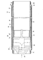
- FIG. 1 is a perspective view of an air diffuser of one embodiment according to the present invention.
- FIG. 2 is an exploded perspective view of the air diffuser shown in FIG. 1
- FIG. 3 is a cross-sectional view of the air diffuser shown in FIG. 1 taken along the line III-III.
- 4A and 4B are views for explaining an elastic film body of the air diffuser shown in FIG. 1, wherein FIG. 4A is a cross-sectional view of the elastic film body (the elastic film body is cut along the line AA in FIG. 1B).
- (B) is a longitudinal sectional view of the elastic film (a sectional view of the elastic film taken along line BB in (A)).
- the air diffuser 10 of the present embodiment has a tube base 20 and an elastic film body 30 covering the outer surface of the tube base 20.
- the tube base 20 and the elastic film body 30 are fixed by bands 41 and 42. Note that, in FIG. 3, arrows indicate the flow of air.
- the tube base 20 includes an adapter 21 and a cylindrical body 26.
- the adapter 21 is a cylindrical body provided with an air inlet 22 at one end along the central axis and the other end along the central axis sealed with a partition 23.
- the air inlet 22 is connected to the blower via a pipe.
- the adapter 21 has an air outlet 24 on a side surface.
- the air outlet 24 blows out the air introduced into the air inlet 22 to the outside.
- Two air outlets 24 are provided at positions facing each other.
- the positions facing each other are positions facing each other with the central axis of the adapter 21 interposed therebetween on the side surface of the adapter 21.
- the adapter 21 has a cylindrical projection 25 at the other end.
- the cylindrical projection 25 is attached to the partition wall 23 and has a projection protruding outward from the other end.
- the size of the tube base material 20 is not particularly limited.
- the outer diameter is in the range of 59 mm to 90 mm, and the axial length is in the range of 500 mm to 1000 mm.
- the material of the adapter 21 and the cylindrical body 26 constituting the tube base material 20 is not particularly limited, but a thermoplastic resin such as a vinyl chloride resin or an ABS resin can be used.
- the adapter 21 and the cylindrical body 26 can be manufactured by, for example, injection molding.
- the elastic membrane 30 is formed in a tubular shape and has a plurality of slits 31 communicating from the inner surface to the outer surface.
- the length of the slit 31 is preferably in a range of 1 mm or more and 2 mm or less. When the length of the slit is within this range, bubbles having a fine and uniform size are easily generated.
- the elastic film body 30 has six protrusions 32 protruding toward the tube base 20 and extending in the axial direction of the tube base 20, curved to the side opposite to the tube base 20, and Two curved portions 33 extending in the axial direction of 20 are provided respectively.
- the six convex portions 32 and the two curved portions 33 are arranged at equal intervals from each other.
- extending in the axial direction of the tube base 20 means extending in a direction parallel to the axial direction of the tube base 20.
- To protrude toward the tube base 20 means that in the cross-sectional view of the elastic film body 30, the inner surface has a convex portion that is convex toward the central axis.
- To be curved to the side opposite to the tube substrate 20 side means to have a curved portion that is convex in the direction from the central axis to the outer periphery in the cross section of the elastic film body 30.
- the convex portion 32 increases the rigidity of the elastic film body 30, stops the air diffusing operation, and causes the elastic film body 30 to twist when the negative pressure and the water pressure are applied to the elastic film body 30. Has a function to make it difficult. Further, when the air diffusing operation is stopped, the convex portion 32 comes into contact with the outer surface of the tube base 20 and changes the shape of the thin portion of the elastic film body 30 where the convex portion 32 is not provided. It has the function of suppressing the amount.
- Each of the protrusions 32 has a thickness in a range of 1 mm to 3 mm, and a width in a range of 5 mm to 15 mm.
- the thickness of the protrusion 32 is the thickness from the inner wall surface (the inner wall surface excluding the protrusion 32 and the curved portion 33) of the elastic film 30 (in other words, the thickness of the elastic film 30 30 (the thickness of the elastic film body 30 excluding the convex portion 32 and the curved portion 33).
- the thickness of the projection 32 is more preferably in the range of 1.5 mm to 2.5 mm, and the width is more preferably in the range of 8 mm to 12 mm. If the thickness of the protrusion 32 is less than 1 mm, the function of increasing the rigidity of the elastic film body 30 may be reduced.
- the thickness of the convex portion 32 exceeds 3 mm, the minimum inner diameter of the elastic film body 30 including the portion where the convex portion 32 is provided becomes smaller than the outer diameter of the tube substrate 20, It becomes difficult to mount the elastic film body 30 on the elastic film body 20. In addition, even when the air diffuser 10 is stopped, the amount of extension of the elastic film body 30 is increased, and the slit 31 may remain open.
- the thickness of the elastic film body 30 (the thickness of the elastic film body 30 excluding the convex portion 32 and the curved portion 33) is preferably in the range of 1.5 mm or more and 2.5 mm or less.
- the width of the projection 32 is less than 5 mm, the function of increasing the rigidity of the elastic film body 30 may be reduced.
- the width of the convex portion 32 exceeds 15 mm, the area of the thin portion of the elastic film body 30 where the convex portion 32 is not provided, that is, the area of the portion which is easily expanded by the pressure of air becomes relatively narrow. In addition, there is a possibility that bubbles may not be stably generated during the diffusing operation.
- the portion where the protrusion 32 is provided may or may not be provided with the slit 31.
- the curved portion 33 has a radius of curvature smaller than the radius of the tube base 20, and thereby has a function of forming a space 35 between the inner surface of the bent portion 33 and the outer surface of the tube base 20.
- Two curved portions 33 are provided at positions facing each other with the central axis interposed therebetween, and the two curved portions 33 are respectively arranged so as to face the air outlets 24 provided in the tube base 20. ing.
- the radius of curvature of the curved portion 33 is preferably 19% to 34% of the radius of the tube base 20.
- a thick portion 34 is provided on the inner surface of the curved portion 33.
- the thick portion 34 prevents the curved portion 33 from being sucked into the air outlet 24 due to the negative pressure generated when the air diffusing operation is stopped.
- the thickness of the thick portion 34 is not particularly limited, but is preferably in a range of 3 mm or more and 5 mm or less.
- a rubber material such as ethylene propylene rubber, silicone rubber, fluorine rubber, urethane rubber or the like can be used.
- the elastic film body 30 can be manufactured by, for example, compression molding or extrusion molding.
- FIGS. 5A and 5B are views for explaining a state of the air diffuser 10 when the air diffuser operation is stopped.
- FIG. FIG. 2B is an enlarged cross-sectional view of a main part of FIG.
- the protrusion 32 of the elastic film body 30 is in contact with the outer surface of the tube base 20.
- the slit 31 of the elastic film body 30 is closed.
- FIG. 6 is a figure explaining the state at the time of the diffusion operation of the air diffuser 10, (A) is a cross-sectional view of the air diffuser 10, (B) is an expanded sectional view of the principal part of (A). It is.
- the air sent to the air inlet 22 passes through the air outlet 24, and the inside surface of the curved portion 33 of the elastic film body 30 and the tube base. It is supplied to the space 35 between the outer surface of the material 20. Due to the air supplied to the space 35, the elastic film body 30 extends outward as a whole.
- the convex portion 32 of the elastic film body 30 is separated from the outer surface of the tube base material 20, and a space is formed between the convex portion 32 and the outer surface of the tube base material 20, and the slit 31 is formed. It is opened and air is released from the opened slit 31 as fine bubbles.
- the diffusing device 10 of the present embodiment configured as described above, when the diffusing operation is stopped, as illustrated in FIG. 5, the protrusions 32 do not cause the elastic film body 30 to twist. Furthermore, by contacting the outer surface of the tube base 20, the amount of change in the shape of the thin portion where the projection 32 is not provided can be reduced. Therefore, according to the air diffuser 10 of the present embodiment, it is possible to suppress the generation of wrinkles of the elastic film body 30 when the air diffusion operation is stopped.
- the elastic film 30 has six convex portions 32, it is possible to further suppress the generation of wrinkles of the elastic film 30 when the air diffusion operation is stopped.
- the convex portion 32 of the elastic film body 30 has a thickness in a range of 1 mm or more and 3 mm or less, and a width of 5 mm or more and 15 mm or less.
- the rigidity of the convex portion 32 is high, and when the diffuser operation is stopped and the negative pressure and the water pressure are applied to the elastic film body 30, the convex portion 32 is hardly deformed, and the convex portion 32 is not provided. The amount of change in the shape of the thin portion can be reduced.
- the width of the convex portion 32 is set to 15 mm or less, the area of the thin portion where the convex portion 32 is not provided, that is, the area of the portion which is easily expanded by the pressure of air is secured, Occasionally, bubbles can be generated stably.
- the tube base 20 includes two air outlets 24, and the curved portion 33 of the elastic film body 30 is provided at a position facing each of the air outlets 24. I have.
- the number of the convex portions 32 of the elastic film body 30 is six, but the number is not limited thereto.
- the number of the protrusions 32 may be one, but is preferably four or more. When four or more protrusions 32 are provided, generation of wrinkles at the time of stoppage of the air diffusing operation can be further suppressed.
- the number of the protrusions 32 is too large, the area of the thin portion where the protrusions 32 are not provided, that is, the area of the portion which is easily expanded by the pressure of air becomes relatively small, and the performance may be deteriorated. There is. For this reason, it is preferable that the number of the convex portions 32 is 10 or less.
- the area ratio of the portion of the inner surface of the elastic film body 30 where the protrusion 32 is provided is preferably in the range of 3% to 32%, and more preferably in the range of 13% to 19%. Is more preferred.
- the number of the curved portions 33 of the elastic film body 30 is two, but is not limited thereto.
- the number of the curved portions 33 may be one, but preferably two or more.
- the elastic film body 30 has a tubular shape, but is not limited to this.
- the elastic film body 30 may be formed in a sheet shape and wound around the tube base 20.
- the convex portions 32 of the elastic film body 30 linearly extend in the axial direction of the tube base 20, but extend in the axial direction of the tube base 20. If it extends, it is not limited to this.
- the protrusion 32 may be spiral or wavy.
- Example 1 As a tube base material, one provided with two air outlets disposed to face left and right with respect to the central axis in a cross section perpendicular to the central axis was prepared.
- the elastic film body two protrusions are disposed above and below the inner surface in a cross section perpendicular to the central axis and opposed to each other with the central axis therebetween, and two convex portions are disposed to face left and right with the central axis therebetween.
- An elastic membrane having a plurality of curved portions was prepared. The outer surface of the tube base is covered with an elastic film so that the curved portion faces the air outlet, and then the tube base and the elastic film are fixed with a band to diffuse the air. was prepared.
- the tube base had an outer diameter of 89.0 mm and a length of 500 mm.
- the elastic membrane had an inner diameter of 91.0 mm, a thickness of 2.0 mm, and a length of 500 mm.
- the projection had a width of 10 mm and a thickness of 2.0 mm.
- the curved portion had a radius of curvature of 10 mm (22.5% with respect to the radius of the tube substrate), and the thick portion had a thickness of 2.0 mm.
- an elastic film body having a plurality of 2 mm long slits communicating from the inner surface to the outer surface was prepared.
- Example 2 As the elastic film body, a convex portion disposed below the inner surface in the cross section, two convex portions disposed at a position where the central angle is 120 degrees with respect to the convex portion, and a central axis interposed therebetween.
- An air diffuser was produced in the same manner as in Example 1, except that an elastic membrane having two curved portions disposed to face left and right was used.
- Example 3 As the elastic film body, four convex portions disposed on the inner surface in the cross section so that the central angle is 90 degrees, and two curved portions disposed to face left and right across the central axis are convex.
- An air diffuser was manufactured in the same manner as in Example 1, except that an elastic film body disposed so that the central angle between the portion and the curved portion was 45 degrees.
- Example 4 As the elastic membrane, an elastic membrane in which six convex portions and two curved portions are arranged at equal intervals in a cross section, and the two curved portions are disposed to face left and right with the central axis interposed therebetween is used. A diffuser was manufactured in the same manner as in Example 1 except that the air diffuser was used.
- Example 5 As a tube base material, one having two air outlets vertically opposed to each other in a cross section is used. As an elastic film body, six projections and two curved portions are respectively equal to each other in a cross section. An air diffuser was manufactured in the same manner as in Example 1 except that elastic film bodies were used at intervals and two curved portions were vertically arranged to face each other across the central axis.
- Example 6 A diffuser was produced in the same manner as in Example 1, except that the elastic film had the same configuration as that of Example 4 except that the width of the protrusion was 5 mm.
- Example 7 A diffuser was produced in the same manner as in Example 1, except that the elastic film had the same configuration as that of Example 4 except that the width of the protrusion was 15 mm.
- Example 8 An air diffuser was produced in the same manner as in Example 1 except that the elastic film had the same configuration as that of Example 4 except that the thickness of the protrusion was 3 mm.
- Example 1 An air diffuser was produced in the same manner as in Example 1, except that an elastic film having no convex portion and no curved portion was used as the elastic film.
- the elastic membrane had an inner diameter of 89.6 mm, a thickness of 1.7 mm, and a length of 500 mm.
- Example 2 As a tube base material, one having two air outlets disposed opposite to each other with a central axis at the top and bottom of the cross section is used. An air diffuser was manufactured in the same manner as in Example 1, except that an elastic film having two curved portions opposed to each other with the axis interposed therebetween was used.
- the air permeability was evaluated based on wet air flow resistance during the air diffusing operation.
- the wet air flow resistance is obtained by measuring the pressure at the inlet of the air diffuser at an air supply rate of 200 L / min (at 20 ° C. and converted to 1 atm), and based on the measured value, the water pressure value of the water depth at which the diffuser is immersed. I asked for it.
- the case where the wet airflow resistance was in the range of 2.8 kPa to 3.8 kPa was judged as “A”, and the case where the wet airflow resistance was out of the above range was judged as “C”.
- the foaming state was evaluated by comparing the foaming state at a position 250 mm away from the air outlet of the air diffuser in the axial direction with the foaming state at a position 500 mm away from the air outlet in the axial direction. As a result of the comparison of the foaming state, it was judged as “A” when it was uniform and “B” when it was uneven.
- the air conveying pipe was connected to a decompression pump, and the inside of the tube substrate was depressurized at ⁇ 50 kPa for 30 seconds. During the depressurization, the outer surface of the elastic film body of the air diffuser was visually observed. When wrinkles were found on the surface of the elastic membrane, the place where the wrinkles occurred was checked.
- the air conveying pipe is connected to the blower again, and after performing the air diffusing operation under the above conditions, the air diffusing operation is stopped.
- the intermittent aeration operation in which the inside of the tube substrate was depressurized under the above conditions by connecting to a vacuum pump was repeated.
- the foaming amount is clearly decreased as the distance from the air outlet increases in the axial direction, and the foaming state is uneven. there were. Further, after the aeration operation was stopped, noticeable wrinkles were generated on the upper portion of the elastic membrane. In the air diffusing device of Comparative Example 2 using the elastic film body having only the curved portion, the foaming state was improved, but wrinkles were generated on the upper and lower portions of the elastic film body after the diffusion operation was stopped. The reason why wrinkles occurred in the lower part is that the tube base material and the elastic film body partially adhered to each other before the air trapped in the lower part after the aeration operation was stopped, and it became difficult for air to escape. Conceivable.
- the foaming state is uniform, and wrinkles are generated in the elastic film after the diffusion operation is stopped. It became difficult to do.
- the air diffusers of Examples 3 to 8 using the elastic film bodies having four or more convex portions no wrinkles were generated in the elastic film bodies even if the intermittent operation was performed three times.
- the air diffusing device of Example 4 no wrinkles were generated in the elastic film body even after performing the intermittent operation 10,000 times.
Landscapes
- Chemical & Material Sciences (AREA)
- Life Sciences & Earth Sciences (AREA)
- Chemical Kinetics & Catalysis (AREA)
- Biodiversity & Conservation Biology (AREA)
- Microbiology (AREA)
- Hydrology & Water Resources (AREA)
- Engineering & Computer Science (AREA)
- Environmental & Geological Engineering (AREA)
- Water Supply & Treatment (AREA)
- Organic Chemistry (AREA)
- Dispersion Chemistry (AREA)
- Aeration Devices For Treatment Of Activated Polluted Sludge (AREA)
Priority Applications (1)
| Application Number | Priority Date | Filing Date | Title |
|---|---|---|---|
| PH1/2021/550156A PH12021550156B1 (en) | 2018-07-25 | 2019-07-05 | Diffuser |
Applications Claiming Priority (2)
| Application Number | Priority Date | Filing Date | Title |
|---|---|---|---|
| JP2018139431A JP6689921B2 (ja) | 2018-07-25 | 2018-07-25 | 散気装置 |
| JP2018-139431 | 2018-07-25 |
Publications (1)
| Publication Number | Publication Date |
|---|---|
| WO2020022035A1 true WO2020022035A1 (ja) | 2020-01-30 |
Family
ID=69181482
Family Applications (1)
| Application Number | Title | Priority Date | Filing Date |
|---|---|---|---|
| PCT/JP2019/026825 Ceased WO2020022035A1 (ja) | 2018-07-25 | 2019-07-05 | 散気装置 |
Country Status (3)
| Country | Link |
|---|---|
| JP (1) | JP6689921B2 (https=) |
| PH (1) | PH12021550156B1 (https=) |
| WO (1) | WO2020022035A1 (https=) |
Families Citing this family (3)
| Publication number | Priority date | Publication date | Assignee | Title |
|---|---|---|---|---|
| BR112022025570A2 (pt) * | 2020-08-27 | 2023-03-28 | Utsunomiya Kogyo Co Ltd | Mecanismo de jateamento de ar comprimido e conduto e bacia de sedimentação usando o mesmo |
| JP7561600B2 (ja) * | 2020-12-21 | 2024-10-04 | 株式会社クボタ | メンブレン式散気装置、散気設備およびメンブレンの製造方法 |
| JP7561601B2 (ja) * | 2020-12-21 | 2024-10-04 | 株式会社クボタ | メンブレン式散気装置および散気設備 |
Citations (7)
| Publication number | Priority date | Publication date | Assignee | Title |
|---|---|---|---|---|
| JP2000263081A (ja) * | 1999-03-19 | 2000-09-26 | Andreas Jaeger | 水を攪拌するための装置 |
| US20010020751A1 (en) * | 2000-03-10 | 2001-09-13 | Gummi-Jager Kg Gmbh & Cie. | Apparatus for aerating water |
| US20020043729A1 (en) * | 2000-02-23 | 2002-04-18 | Wilfried Ott | Gasification device |
| JP2002263680A (ja) * | 2001-03-13 | 2002-09-17 | Mitsubishi Kakoki Kaisha Ltd | 散気装置 |
| JP2005081203A (ja) * | 2003-09-05 | 2005-03-31 | Sumitomo Heavy Ind Ltd | 散気装置及び散気システム |
| JP2009274016A (ja) * | 2008-05-15 | 2009-11-26 | Daicen Membrane Systems Ltd | チューブ型メンブレンディフューザ |
| JP2011218342A (ja) * | 2010-04-09 | 2011-11-04 | Friederike Ott | 液体内にガスを断続的に供給するガス供給装置 |
-
2018
- 2018-07-25 JP JP2018139431A patent/JP6689921B2/ja active Active
-
2019
- 2019-07-05 WO PCT/JP2019/026825 patent/WO2020022035A1/ja not_active Ceased
- 2019-07-05 PH PH1/2021/550156A patent/PH12021550156B1/en unknown
Patent Citations (7)
| Publication number | Priority date | Publication date | Assignee | Title |
|---|---|---|---|---|
| JP2000263081A (ja) * | 1999-03-19 | 2000-09-26 | Andreas Jaeger | 水を攪拌するための装置 |
| US20020043729A1 (en) * | 2000-02-23 | 2002-04-18 | Wilfried Ott | Gasification device |
| US20010020751A1 (en) * | 2000-03-10 | 2001-09-13 | Gummi-Jager Kg Gmbh & Cie. | Apparatus for aerating water |
| JP2002263680A (ja) * | 2001-03-13 | 2002-09-17 | Mitsubishi Kakoki Kaisha Ltd | 散気装置 |
| JP2005081203A (ja) * | 2003-09-05 | 2005-03-31 | Sumitomo Heavy Ind Ltd | 散気装置及び散気システム |
| JP2009274016A (ja) * | 2008-05-15 | 2009-11-26 | Daicen Membrane Systems Ltd | チューブ型メンブレンディフューザ |
| JP2011218342A (ja) * | 2010-04-09 | 2011-11-04 | Friederike Ott | 液体内にガスを断続的に供給するガス供給装置 |
Also Published As
| Publication number | Publication date |
|---|---|
| PH12021550156B1 (en) | 2024-03-22 |
| JP6689921B2 (ja) | 2020-04-28 |
| PH12021550156A1 (en) | 2021-09-13 |
| JP2020014999A (ja) | 2020-01-30 |
Similar Documents
| Publication | Publication Date | Title |
|---|---|---|
| JP4781302B2 (ja) | 散気方法及び水処理運転方法 | |
| WO2020022035A1 (ja) | 散気装置 | |
| JP5366785B2 (ja) | 散気管 | |
| JP2005081203A (ja) | 散気装置及び散気システム | |
| JP5349370B2 (ja) | 散気管および散気装置 | |
| JP2009274016A (ja) | チューブ型メンブレンディフューザ | |
| JP2007117871A (ja) | 多孔膜材及び散気装置 | |
| CN107010715B (zh) | 扩散器组件及其制造方法以及包括该组件的废水处理槽 | |
| JP5557949B2 (ja) | メンブレン式散気装置 | |
| CN103118991B (zh) | 膜片式散气装置 | |
| JP5562020B2 (ja) | メンブレン式散気装置 | |
| JP6246610B2 (ja) | 散気装置 | |
| JP5900299B2 (ja) | 散気方法 | |
| JP2014079729A (ja) | 散気用弾性膜及び該散気用弾性膜を備えた散気体 | |
| JP4528219B2 (ja) | 散気装置 | |
| JP5334740B2 (ja) | メンブレン式散気装置 | |
| JP2006150268A (ja) | 散気方法 | |
| KR102198651B1 (ko) | 산기 장치 및 산기 방법 | |
| WO2014061758A1 (ja) | 散気用弾性材、該散気用弾性材を備えた散気体、及び、該散気体を用いた散気方法 | |
| EP3450002B1 (en) | Diffuser assembly and manufacturing method thereof | |
| JP2005329329A (ja) | 散気装置及び散気方法 | |
| JP6107326B2 (ja) | 散気装置 | |
| TWI601696B (zh) | Diffusion method | |
| JP2021049499A (ja) | 散気装置 | |
| JP2013121569A (ja) | 筒状散気装置とその製造方法 |
Legal Events
| Date | Code | Title | Description |
|---|---|---|---|
| 121 | Ep: the epo has been informed by wipo that ep was designated in this application |
Ref document number: 19840881 Country of ref document: EP Kind code of ref document: A1 |
|
| NENP | Non-entry into the national phase |
Ref country code: DE |
|
| 122 | Ep: pct application non-entry in european phase |
Ref document number: 19840881 Country of ref document: EP Kind code of ref document: A1 |