WO2020022018A1 - リソース割当装置、リソース管理システム、および、リソース割当プログラム - Google Patents
リソース割当装置、リソース管理システム、および、リソース割当プログラム Download PDFInfo
- Publication number
- WO2020022018A1 WO2020022018A1 PCT/JP2019/026624 JP2019026624W WO2020022018A1 WO 2020022018 A1 WO2020022018 A1 WO 2020022018A1 JP 2019026624 W JP2019026624 W JP 2019026624W WO 2020022018 A1 WO2020022018 A1 WO 2020022018A1
- Authority
- WO
- WIPO (PCT)
- Prior art keywords
- resource
- allocation
- physical
- virtual
- cpu
- Prior art date
- Legal status (The legal status is an assumption and is not a legal conclusion. Google has not performed a legal analysis and makes no representation as to the accuracy of the status listed.)
- Ceased
Links
Images



Classifications
-
- G—PHYSICS
- G06—COMPUTING OR CALCULATING; COUNTING
- G06F—ELECTRIC DIGITAL DATA PROCESSING
- G06F9/00—Arrangements for program control, e.g. control units
- G06F9/06—Arrangements for program control, e.g. control units using stored programs, i.e. using an internal store of processing equipment to receive or retain programs
- G06F9/46—Multiprogramming arrangements
- G06F9/50—Allocation of resources, e.g. of the central processing unit [CPU]
- G06F9/5005—Allocation of resources, e.g. of the central processing unit [CPU] to service a request
- G06F9/5027—Allocation of resources, e.g. of the central processing unit [CPU] to service a request the resource being a machine, e.g. CPUs, Servers, Terminals
- G06F9/5044—Allocation of resources, e.g. of the central processing unit [CPU] to service a request the resource being a machine, e.g. CPUs, Servers, Terminals considering hardware capabilities
-
- G—PHYSICS
- G06—COMPUTING OR CALCULATING; COUNTING
- G06F—ELECTRIC DIGITAL DATA PROCESSING
- G06F9/00—Arrangements for program control, e.g. control units
- G06F9/06—Arrangements for program control, e.g. control units using stored programs, i.e. using an internal store of processing equipment to receive or retain programs
- G06F9/44—Arrangements for executing specific programs
- G06F9/455—Emulation; Interpretation; Software simulation, e.g. virtualisation or emulation of application or operating system execution engines
- G06F9/45533—Hypervisors; Virtual machine monitors
- G06F9/45558—Hypervisor-specific management and integration aspects
-
- G—PHYSICS
- G06—COMPUTING OR CALCULATING; COUNTING
- G06F—ELECTRIC DIGITAL DATA PROCESSING
- G06F9/00—Arrangements for program control, e.g. control units
- G06F9/06—Arrangements for program control, e.g. control units using stored programs, i.e. using an internal store of processing equipment to receive or retain programs
- G06F9/46—Multiprogramming arrangements
- G06F9/50—Allocation of resources, e.g. of the central processing unit [CPU]
- G06F9/5061—Partitioning or combining of resources
- G06F9/5077—Logical partitioning of resources; Management or configuration of virtualized resources
-
- G—PHYSICS
- G06—COMPUTING OR CALCULATING; COUNTING
- G06F—ELECTRIC DIGITAL DATA PROCESSING
- G06F9/00—Arrangements for program control, e.g. control units
- G06F9/06—Arrangements for program control, e.g. control units using stored programs, i.e. using an internal store of processing equipment to receive or retain programs
- G06F9/44—Arrangements for executing specific programs
- G06F9/455—Emulation; Interpretation; Software simulation, e.g. virtualisation or emulation of application or operating system execution engines
- G06F9/45533—Hypervisors; Virtual machine monitors
- G06F9/45558—Hypervisor-specific management and integration aspects
- G06F2009/45562—Creating, deleting, cloning virtual machine instances
-
- G—PHYSICS
- G06—COMPUTING OR CALCULATING; COUNTING
- G06F—ELECTRIC DIGITAL DATA PROCESSING
- G06F2209/00—Indexing scheme relating to G06F9/00
- G06F2209/50—Indexing scheme relating to G06F9/50
- G06F2209/503—Resource availability
Definitions
- the present invention relates to a resource allocation device, a resource management system, and a resource allocation program.
- VM virtual machine
- the virtual device that is a component of the VM is, for example, a virtual CPU obtained by virtualizing a physical CPU.
- IaaS Infrastructure as service
- OpenStack registered trademark
- Non-Patent Document 1 assigns which resource (computer resource, network resource) to which VM. Is provided.
- each VM is assigned by performing a two-stage process of selecting (filtering) a resource candidate to which a VM can be assigned and assigning a priority (waiting) to select a resource to which the VM is assigned from the selected resource candidate. Identify resources to be assigned.
- a virtual CPU accommodated by a VM is an allocation target and an allocation destination of the virtual CPU is a physical CPU.
- One VM accommodates one or more virtual CPUs.
- One or more virtual CPUs operate on one physical CPU. Note that one physical CPU may be occupied (dedicated) by one virtual CPU (dedicated allocation method), or one physical CPU may be shared (shared) by a plurality of virtual CPUs. Is also good.
- An infrastructure operator who provides an IaaS service can set an overcommit ratio of how many virtual CPUs are allocated to one physical CPU for a physical CPU of the shared allocation method (Non-Patent Document 2).
- an overcommit ratio of how many virtual CPUs are allocated to one physical CPU for a physical CPU of the shared allocation method (Non-Patent Document 2).
- OpenStack "Filter @ Scheduler", [online], [searched on July 9, 2018], Internet ⁇ URL: https://docs.openstack.org/nova/latest/user/filter-scheduler.html#filtering> OpenStack, "CPU topologies”, [online], [searched on July 9, 2018], Internet ⁇ URL: https://docs.openstack.org/nova/pike/admin/cpu-topologies.html>
- a service provider that provides a VM requests a necessary resource amount, and an infrastructure operator uses a scheduling function based on the requested resource to select an appropriate resource.
- the information sharing of the IaaS service infrastructure is not performed between the infrastructure operator and the service provider who provides the service to each consumer after receiving the provision of the infrastructure. Had been divided. Therefore, both have the following problems.
- the infrastructure operator can reduce the overcommit rate or adopt an occupancy allocation method.
- the accommodation efficiency does not increase.
- the overcommit ratio is set too high in order to increase the profit of the infrastructure operator, there is a problem that the service quality is deteriorated for the service provider due to a scarce resource amount when executing the service content with a large load. .
- the appropriate resources that the service provider should request from the infrastructure operator may change according to the service content of the service provider.
- a physical CPU capable of executing network processing such as packet transfer processing and connection connection processing at high speed be assigned as a virtual CPU used for a network function VM.
- a physical CPU having a high-performance screen drawing capability is assigned to a VM for a network function, the screen drawing capability is not used and resources are wasted.
- the main object of the present invention is to realize resource allocation suitable for both the resource providing side and the resource using side.
- a resource allocation device has the following features.
- the present invention receives an allocation request that specifies the usage amount of a physical resource used by a virtual resource and the characteristics of the physical resource for each virtual resource, and uses an allocation request that matches the characteristics of the physical resource specified by the allocation request.
- a filtering unit for selecting resources Waiting for selecting the physical resource to which the virtual resource is to be assigned based on the available usage of each of the selected allocation resources and the usage of the physical resource specified in the allocation request Department and
- a resource allocating unit that allocates the virtual resource specified by the allocation request to the physical resource selected as the allocation destination.
- resource allocation suitable for the resource use side is achieved, and the allocation resource is selected based on the available usage of the allocation resource.
- resource allocation suitable for the resource providing side is achieved.
- the present invention is characterized in that the weighting unit preferentially selects the virtual resource as a destination to which the virtual resource is allocated, as the available usage amount of each of the selected allocation resources is smaller.
- the present invention provides a resource management system including the resource allocating apparatus, a terminal of an infrastructure operator that operates the resource for allocation, and a terminal of a service provider that receives the allocation resource and provides a service.
- the system The infrastructure operator terminal notifies the service provider terminal of performance data and characteristic data for each of the allocation resources,
- the service provider's terminal specifies the usage amount of the physical resource used by the virtual resource from the notified performance data for the allocation resource, and from the notified characteristic data for the allocation resource,
- the allocation request is created by specifying characteristics of the physical resource used by the virtual resource.
- the terminal of the infrastructure operator notifies, as performance data for each of the allocation resources, a CPU usage rate when the allocation resource is a physical CPU for each process type operated on the physical CPU.
- the terminal of the service provider determines the CPU usage rate used by the virtual resource based on the CPU usage rate for each notified process type from the process type of the service input in advance, using the physical resource usage. It is characterized in that it is obtained as a quantity.
- resource allocation suitable for both the resource providing side and the resource using side can be realized.
- FIG. 1 is a configuration diagram of a resource management system according to an embodiment.
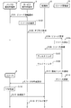
- FIG. 7 is a sequence diagram illustrating a resource allocation process according to the embodiment.
- 9 is a table showing resource management information according to the embodiment.
- 5 is a table showing a resource allocation definition file according to the embodiment. 4 shows a first table stored in a resource management unit according to the embodiment. 5 shows a second table and a third table stored in a resource management unit according to the embodiment. 9 shows a fourth table stored in the resource management unit according to the embodiment.
- FIG. 1 is a configuration diagram of the resource management system.
- a resource allocating apparatus 1 an allocation resource 2, a service provider terminal (service provider terminal) 3, and an infrastructure operator terminal (infrastructure operator terminal) 4 are connected via a network.
- Each of these devices is configured as a computer having a CPU (Central Processing Unit), a memory, a storage unit (storage unit) such as a hard disk, and a network interface.
- a CPU Central Processing Unit
- a memory a storage unit (storage unit) such as a hard disk
- a network interface such as a hard disk
- a network interface such as a hard disk
- a control unit control unit
- the infrastructure operator terminal 4 provides the allocation resource 2 to the service provider terminal 3 as IaaS.
- the resource allocation device 1 manages the status of the allocation resources 2 and is in charge of individual resource allocation processing.
- the infrastructure operator terminal 4 provides the information on the allocation resources 2 acquired from the resource allocation device 1 to the service provider terminal 3 as the resource management information 31 (details in FIG. 3).
- the service provider terminal 3 provides a service to a customer (not shown).
- the service provider informs the service provider terminal 3 of the individual process types (“packet processing”, “batch processing”, etc.) for constructing the service to be provided and the frequency at which the process types are executed by the VM. Enter in.
- the service provider terminal 3 creates, as a resource allocation definition file 32, details of a resource requested to construct a service to be provided, based on the provided resource management information 31 and information input in advance.
- the resource allocation is requested by notifying the resource allocation device 1 of the resource allocation definition file 32 (see FIG. 4 for details).
- the infrastructure operator terminal 4 transmits the resource management information 31 and the service provider terminal 3 transmits the resource allocation definition file 32, information exchange is performed between the two in advance.
- the resource allocation device 1 includes, as the processing unit 10, a resource allocation determination unit 11, a filtering unit 12, a weighting unit 13, and a virtual machine generation unit (resource allocation unit) 14. Further, the resource allocation device 1 has a resource management unit 15 for storing data handled by the processing unit 10 (for details, see FIGS. 5 to 7).
- the resource allocation determination unit 11 assigns each requested virtual CPU (virtual resource) based on the characteristics of the allocation resource 2 managed by the resource management unit 15 and the characteristics of the virtual CPU requested by the resource allocation definition file 32.
- the scheduling is controlled so as to be allocated to an appropriate physical CPU (physical resource). That is, the resource allocation determination unit 11 instructs the other processing units (the filtering unit 12, the waiting unit 13, and the virtual machine generation unit 14) to perform the following three-stage scheduling.
- the filtering unit 12 selects a physical CPU having the same characteristics as those of the virtual CPU.
- the waiting unit 13 selects a physical CPU that matches the usage rate of the virtual CPU as the allocation destination for the selected physical CPU.
- the virtual machine generation unit 14 allocates a virtual CPU to the physical CPU to which the virtual machine is allocated, and generates a VM (virtual machine) that accommodates the virtual CPU.
- the resource management unit 15 stores data used in each stage of scheduling, and reads and writes the stored data in response to a request from each processing unit 10.
- FIG. 2 is a sequence diagram illustrating the resource allocation process. The flow when the service provider deploys the VM is shown below.
- the infrastructure operator terminal 4 provides the information on the allocation resource 2 acquired from the resource allocation device 1 to the service provider terminal 3 as the resource management information 31 (FIG. 3).
- the service provider terminal 3 selects a resource requested to construct a service to be provided from the allocation resources 2 based on the provided resource management information 31 and information input in advance.
- the service provider terminal 3 instructs the resource allocation definition unit 11 of the resource allocation device 1 to report the resource allocation definition file 32 describing the selection result of S102, thereby instructing resource allocation (deployment) (FIG. 4).
- step S104 the resource allocation determination unit 11 requests the resource management unit 15 from the allocation resource 2 a resource that can be currently allocated.
- the resource management unit 15 reads a currently assignable resource from the stored data.
- step S106 the resource management unit 15 returns the data read in step S105 to the resource allocation determination unit 11 as resource candidates (FIG. 5).
- the filtering unit 12 selects a physical CPU having the same characteristics as those of the virtual CPU specified in the resource allocation definition file 32 for the resource candidates in S106 notified from the resource allocation determining unit 11 (S107). (Fig. 6).
- the waiting unit 13 selects a physical CPU that matches the usage rate of the virtual CPU as the assignment destination for the physical CPU selected in S107 (FIG. 6).
- the waiting unit 13 notifies the resource management unit 15 of the physical CPU to which the data is allocated in step S108 as the allocated resource.
- the resource management unit 15 updates the managed resource so as to match the status of the allocation resource 2 after the virtual CPU is allocated to the allocation resource notified in S111 (FIG. 7).
- step S113 the virtual machine generation unit 14 allocates a virtual CPU to the physical CPU to which the virtual CPU is allocated in step S108, and instructs the allocation resource 2 to generate a VM (virtual machine) accommodating the virtual CPU.
- the allocation resource 2 receives the instruction in S113, and generates a virtual CPU and a VM accommodating the virtual CPU.
- step S115 the allocation resource 2 notifies the virtual machine generation unit 14 that the VM generation processing in S114 has been completed.
- step S116 the resource allocation determination unit 11 notifies the service provider terminal 3 that the processing of the deployment request in step S103 has been completed.
- FIG. 3 is a table showing the resource management information 31.
- the resource management information 31 includes a benchmark list 31a indicating the performance of the allocation resource 2 and a processing characteristic parameter list 31b indicating the processing characteristics of the allocation resource 2.
- the benchmark list 31a is data indicating the usage status of how much resource is consumed by executing the process type on the allocation resource 2 for each process type such as packet processing.
- FIG. 3 illustrates the CPU usage rate as an example of the usage status of the benchmark list 31a.
- the CPU usage rate may be, for example, an average value of the CPU usage rate measured under a predetermined environment, or a maximum value of the CPU usage rate when the process is started. Also, in FIG.
- the processing characteristic parameter list 31b is data that associates the processing characteristic of the allocation resource 2 with the characteristic value.
- the processing characteristic may be, for example, the number of activations per unit time illustrated in FIG. 3 or the execution time at the time of executing the processing.
- the characteristic value is an ID such as F1, F2, F3 assigned to the range of the processing characteristic.
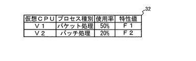
- FIG. 4 is a table showing the resource allocation definition file 32.
- the resource allocation definition file 32 includes, for each virtual CPU requesting allocation, a process type to be operated on the virtual CPU, a load amount such as a CPU usage rate requested in the process type, and an execution frequency in the process type. This is data for associating with processing characteristics. For example, it is assumed that the following information regarding the service to be provided has been input to the service provider terminal 3 in advance from the service provider. -Execute packet processing 5 times. -Execute batch processing 30 times.
- the service provider terminal 3 refers to the benchmark list 31a and obtains a CPU usage rate of 50% corresponding to packet processing and a CPU usage rate of 20% corresponding to batch processing.
- the service provider terminal 3 refers to the processing characteristic parameter list 31b to obtain a characteristic value F1 corresponding to packet processing and a characteristic value F2 corresponding to batch processing. Then, based on the obtained information, the service provider terminal 3 requests a VM including a virtual CPU “V1” that operates packet processing and a virtual CPU “V2” that operates batch processing. An assignment definition file 32 is created.
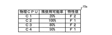
- FIG. 5 shows a first table 15a stored in the resource management unit 15.
- the first table 15a is a currently assignable resource candidate read by the resource management unit 15 in S105.
- the currently available remaining CPU usage rate (remaining available rate) is associated with the characteristic value of the physical CPU. For example, since the remaining available rate of the physical CPU “C1” is 20%, another virtual CPU is already allocated. That is, when a new virtual CPU is allocated to the physical CPU “C1”, the shared allocation method is used.
- the physical CPU “2” has a remaining available rate of 100%, and thus has not been assigned any virtual CPU at the present time. That is, when a new virtual CPU is assigned to the physical CPU “C2”, an occupancy assignment method may be used.
- FIG. 6 shows the second table 15b and the third table 15c stored in the resource management unit 15.
- the second table 15b is a result of the filtering unit 12 collating the characteristic value of the physical CPU in the first table 15a with the characteristic value of the virtual CPU specified in the resource allocation definition file 32 as S107.
- a combination of a virtual CPU and a physical CPU as an assignment destination candidate is set to “candidate” when their characteristic values are the same, and is set to “no” when the characteristic values are different.
- the filtering unit 12 may adopt a physical CPU of the first table 15a having a remaining available rate equal to or higher than the usage rate of the virtual CPU specified in the resource allocation definition file 32 as a “candidate”.
- the waiting unit 13 determines the order of the third table 15c for the allocation destination candidates corresponding to the same virtual CPU, in the order of the remaining availability rate in the first table 15a. For example, in the virtual CPU “V1”, two physical CPUs C2 and C4 are allocation destination candidates. Among them, the remaining available rate “50%” of the physical CPU “C4” is smaller than the remaining available rate “100%” of the physical CPU “C2”, so that the physical CPU “C4” ranks first.
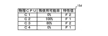
- FIG. 7 shows a fourth table 15d stored in the resource management unit 15.
- the fourth table 15d shows a result of the update processing (S112) of the first table 15a after the assignment destination candidate having the first rank of the third table 15c is determined as the assignment destination.
- the remaining available rate of the physical CPU “C1” has been reduced from “20%” to “0%”. This is because, as a result of the virtual machine generation unit 14 allocating the virtual CPU “V2” to the physical CPU “C1”, the usage rate “20%” of the batch process specified by the virtual CPU “V2” in the resource allocation definition file 32 is reduced. Because it was consumed.
- the remaining available rate of the physical CPU “C4” has been reduced from “50%” to “0%”.
- the server platform technology for constructing and operating a computer system is characterized by the characteristics of the virtual CPUs ascertained by the service provider and the characteristics of the physical CPUs ascertained by the infrastructure operator.
- the resource allocation device 1 can appropriately determine the resources to be allocated.
- the allocation result by the resource allocation device 1 can satisfy the demand of the service provider and the demand of the infrastructure operator in a well-balanced manner as described below.
- the service provider can provide the service content smoothly (without stopping or running out of performance) by the filtering unit 12 filtering out the resources that do not conform to the resource allocation definition file 32 in advance.
- the waiting unit 13 determines the resource selection order based on the remaining available rates in the resource management unit 15 in the order in which the resource use efficiency is good.
- the infrastructure operator can efficiently accommodate the VM in the allocation resource 2 without considering a parameter value such as an overcommit ratio for each physical CPU.
- the infrastructure operator could select the dedicated allocation method or the shared allocation method for each physical CPU as an OpenStack operation parameter, and could set the overcommit ratio in the shared allocation method. Inputting an operation command such as which VM to set a parameter to requires a trial and error based on experience and intuition of an infrastructure operator.
- the allocation resources 2 according to the present invention are illustrated as three as shown in FIG. 1, but the number and configuration are not limited to these.
- hardware resources of a general computer can be realized by a program that operates as each unit of the resource allocation device 1, the service provider terminal 3, and the infrastructure operator terminal 4. This program can be distributed via a communication line, or recorded on a recording medium such as a CD-ROM and distributed.
Landscapes
- Engineering & Computer Science (AREA)
- Software Systems (AREA)
- Theoretical Computer Science (AREA)
- Physics & Mathematics (AREA)
- General Engineering & Computer Science (AREA)
- General Physics & Mathematics (AREA)
- Data Exchanges In Wide-Area Networks (AREA)
- Stored Programmes (AREA)
- Management, Administration, Business Operations System, And Electronic Commerce (AREA)
- Debugging And Monitoring (AREA)
Abstract
【課題】リソースの提供側と利用側との双方に適したリソース割当を実現すること。 【解決手段】リソース割当装置1は、仮想CPUが使用する物理CPUの使用量および物理CPUの特性を仮想CPUごとに規定した割当要求を受け、割当要求で指定された物理CPUの特性に合致する割当用リソース2を選択するフィルタリング部12と、選択された各割当用リソース2の使用可能な使用量と、割当要求で指定された物理CPUの使用量とをもとに、仮想CPUの割当先となる物理CPUを選択するウェイティング部13と、割当先として選定された物理CPUに対して、割当要求で指定された仮想CPUを割り当てる仮想マシン生成部14とを有する。
Description
本発明は、リソース割当装置、リソース管理システム、および、リソース割当プログラムに関する。
コンピュータシステムを構築および稼動させるためのサーバ基盤技術として、物理的な計算機資源(リソース)を仮想化した仮想デバイスを用いた仮想計算機であるVM(Virtual Machine)が普及している。VMの構成要素となる仮想デバイスとは、例えば、物理CPUを仮想化した仮想CPUなどである。
VMをインフラとして提供するサービス(IaaS:Infrastructure as a Service)に向けて、例えば、非特許文献1に記載のOpenStack(登録商標)は、どのリソース(計算機リソース、ネットワークリソース)をどのVMに割り当てるかを規定するスケジューリング機能を提供している。このスケジューリング機能では、VMを割当可能なリソース候補の選択(フィルタリング)と、選択されたリソース候補からVMを割り当てるリソースを選定するための優先度付け(ウェイティング)という2段階の処理により、各VMの割当先となるリソースを特定する。
以下では、VMが収容する仮想CPUを割当対象とし、その仮想CPUの割当先を物理CPUとして説明する。1台のVMには、1つ以上の仮想CPUが収容される。1つの物理CPUには、1つ以上の仮想CPUが動作している。なお、1つの物理CPUを1つの仮想CPUが占有(dedicated)する方式(占有割当方式)としてもよいし、1つの物理CPUを複数の仮想CPUで共有(shared)する方式(共有割当方式)としてもよい。
IaaSサービスを提供するインフラ運用者は、共有割当方式の物理CPUについて、1つの物理CPU上に何台の仮想CPUを割り当てるかというオーバーコミット率を設定することができる(非特許文献2)。オーバーコミット率を上げて1つの物理CPU上に多くの仮想CPUを割り当てることで、インフラ運用者にとってはリソースの利用効率が高まり、収益性が向上する。
OpenStack、"Filter Scheduler"、[online]、[2018年7月9日検索]、インターネット〈URL:https://docs.openstack.org/nova/latest/user/filter-scheduler.html#filtering〉
OpenStack、"CPU topologies"、[online]、[2018年7月9日検索]、インターネット〈URL:https://docs.openstack.org/nova/pike/admin/cpu-topologies.html〉
一般的なIaaS基盤では、VMを提供するサービス提供者が必要なリソース量を要求し、インフラ運用者は要求されたリソースに基づきスケジューリング機能を利用し適切なリソースを選定する。
ここで、インフラ運用者と、インフラの提供を受けて各消費者にサービスを提供するサービス提供者との間では、IaaSサービスのインフラについての情報共有がなされていないことが多く、両者の情報共有が分断されてしまっていた。そのため、両者にとって、それぞれ以下の問題があった。
ここで、インフラ運用者と、インフラの提供を受けて各消費者にサービスを提供するサービス提供者との間では、IaaSサービスのインフラについての情報共有がなされていないことが多く、両者の情報共有が分断されてしまっていた。そのため、両者にとって、それぞれ以下の問題があった。
本来は少ない負荷で済むようなサービス内容であっても、サービス提供者によって過大なリソース量が要求されてしまうと、インフラ運用者はオーバーコミット率を下げたり占有割当方式を採用したりすることにより、収容効率が上がらないという問題があった。
インフラ運用者の利益を大きくするためにオーバーコミット率を高く設定しすぎると、大きい負荷のサービス内容を実行するときには乏しいリソース量により、サービス提供者にとってはサービス品質が劣化してしまう問題があった。
インフラ運用者の利益を大きくするためにオーバーコミット率を高く設定しすぎると、大きい負荷のサービス内容を実行するときには乏しいリソース量により、サービス提供者にとってはサービス品質が劣化してしまう問題があった。
なお、サービス提供者がインフラ運用者に要求すべき適切なリソースは、サービス提供者のサービス内容に応じて変化することもある。例えば、ネットワーク機能向けVMに使用される仮想CPUとして、パケット転送処理やコネクション接続処理などのネットワーク処理を高速に実行可能な物理CPUが割り当てられることが好ましい。一方で、高性能な画面描画能力を有する物理CPUをネットワーク機能向けVMに割り当ててしまっても、その画面描画能力は使用されずにリソースの無駄となってしまう。
そこで、本発明は、リソースの提供側と利用側との双方に適したリソース割当を実現することを、主な課題とする。
前記課題を解決するために、本発明のリソース割当装置は、以下の特徴を有する。
本発明は、仮想リソースが使用する物理リソースの使用量および前記物理リソースの特性を前記仮想リソースごとに規定した割当要求を受け、前記割当要求で指定された前記物理リソースの特性に合致する割当用リソースを選択するフィルタリング部と、
選択された各前記割当用リソースの使用可能な使用量と、前記割当要求で指定された前記物理リソースの使用量とをもとに、前記仮想リソースの割当先となる前記物理リソースを選定するウェイティング部と、
割当先として選定された前記物理リソースに対して、前記割当要求で指定された前記仮想リソースを割り当てるリソース割当部とを有することを特徴とする。
本発明は、仮想リソースが使用する物理リソースの使用量および前記物理リソースの特性を前記仮想リソースごとに規定した割当要求を受け、前記割当要求で指定された前記物理リソースの特性に合致する割当用リソースを選択するフィルタリング部と、
選択された各前記割当用リソースの使用可能な使用量と、前記割当要求で指定された前記物理リソースの使用量とをもとに、前記仮想リソースの割当先となる前記物理リソースを選定するウェイティング部と、
割当先として選定された前記物理リソースに対して、前記割当要求で指定された前記仮想リソースを割り当てるリソース割当部とを有することを特徴とする。
これにより、物理リソースの特性に合致する割当用リソースを選択することで、リソースの利用側に適したリソース割当となり、割当用リソースの使用可能な使用量をもとに割当用リソースを選択することで、リソースの提供側に適したリソース割当となる。
本発明は、前記ウェイティング部が、選択された各前記割当用リソースの使用可能な使用量が少ないほど、優先的に前記仮想リソースの割当先として選定することを特徴とする。
これにより、用意する割当用リソースの総数を節約できることで、割当用リソースの提供者の収益性が向上する。
本発明は、前記のリソース割当装置と、前記割当用リソースを運用するインフラ運用者の端末と、前記割当用リソースを受けてサービスを提供するサービス提供者の端末とを含めて構成されるリソース管理システムであって、
前記インフラ運用者の端末が、前記割当用リソースごとの性能データおよび特性データを前記サービス提供者の端末に通知し、
前記サービス提供者の端末が、通知された前記割当用リソースごとの性能データから前記仮想リソースが使用する前記物理リソースの使用量を特定するとともに、通知された前記割当用リソースごとの特性データから前記仮想リソースが使用する前記物理リソースの特性を特定することで、前記割当要求を作成することを特徴とする。
前記インフラ運用者の端末が、前記割当用リソースごとの性能データおよび特性データを前記サービス提供者の端末に通知し、
前記サービス提供者の端末が、通知された前記割当用リソースごとの性能データから前記仮想リソースが使用する前記物理リソースの使用量を特定するとともに、通知された前記割当用リソースごとの特性データから前記仮想リソースが使用する前記物理リソースの特性を特定することで、前記割当要求を作成することを特徴とする。
これにより、インフラ運用者とサービス提供者との間の情報共有により、双方に都合の良い物理リソースが割り当てられる。
本発明は、前記インフラ運用者の端末が、前記割当用リソースごとの性能データとして、前記割当用リソースが物理CPUであるときのCPU使用率を、物理CPU上で動作させるプロセス種別ごとに通知し、
前記サービス提供者の端末が、事前に入力されているサービスのプロセス種別から、通知されたプロセス種別ごとのCPU使用率をもとに、前記仮想リソースが使用するCPU使用率を前記物理リソースの使用量として求めることを特徴とする。
前記サービス提供者の端末が、事前に入力されているサービスのプロセス種別から、通知されたプロセス種別ごとのCPU使用率をもとに、前記仮想リソースが使用するCPU使用率を前記物理リソースの使用量として求めることを特徴とする。
これにより、サービス提供者は、自身の提供するサービス内容に適した物理リソースの割当要求をインフラ運用者に通知できる。
本発明によれば、リソースの提供側と利用側との双方に適したリソース割当を実現することができる。
以下、本発明の一実施形態について、図面を参照して詳細に説明する。
図1は、リソース管理システムの構成図である。
リソース管理システムは、リソース割当装置1と、割当用リソース2と、サービス提供者端末(サービス提供者の端末)3と、インフラ運用者端末(インフラ運用者の端末)4とがネットワークで接続されて構成される。これらの各装置は、それぞれCPU(Central Processing Unit)と、メモリと、ハードディスクなどの記憶手段(記憶部)と、ネットワークインタフェースとを有するコンピュータとして構成される。
このコンピュータは、CPUが、メモリ上に読み込んだプログラム(アプリケーションや、その略のアプリとも呼ばれる)を実行することにより、各処理部により構成される制御部(制御手段)を動作させる。
リソース管理システムは、リソース割当装置1と、割当用リソース2と、サービス提供者端末(サービス提供者の端末)3と、インフラ運用者端末(インフラ運用者の端末)4とがネットワークで接続されて構成される。これらの各装置は、それぞれCPU(Central Processing Unit)と、メモリと、ハードディスクなどの記憶手段(記憶部)と、ネットワークインタフェースとを有するコンピュータとして構成される。
このコンピュータは、CPUが、メモリ上に読み込んだプログラム(アプリケーションや、その略のアプリとも呼ばれる)を実行することにより、各処理部により構成される制御部(制御手段)を動作させる。
インフラ運用者端末4は、割当用リソース2をIaaSとして、サービス提供者端末3に提供する。リソース割当装置1は、割当用リソース2の状況を管理するとともに、個別のリソース割当処理を担当する。そして、インフラ運用者端末4は、リソース割当装置1から取得した割当用リソース2に関する情報を、リソース管理情報31としてサービス提供者端末3に提供する(詳細は図3)。
サービス提供者端末3は、図示しない顧客に向けてサービスを提供する。サービス提供者は、提供するサービスを構築するための個々のプロセス種別(「パケット処理」、「バッチ処理」など)と、そのプロセス種別をVMで実行させる頻度とを、サービス提供者端末3に事前に入力しておく。
サービス提供者端末3は、提供されたリソース管理情報31と、事前に入力された情報とをもとに、提供するサービスを構築するために要求するリソースの詳細をリソース割当定義ファイル32として作成し、そのリソース割当定義ファイル32をリソース割当装置1に通知することで、リソースの割当を要求する(詳細は図4)。
つまり、インフラ運用者端末4がリソース管理情報31を送信し、サービス提供者端末3がリソース割当定義ファイル32を送信することで、両者間で事前の情報交換が行われる。
サービス提供者端末3は、図示しない顧客に向けてサービスを提供する。サービス提供者は、提供するサービスを構築するための個々のプロセス種別(「パケット処理」、「バッチ処理」など)と、そのプロセス種別をVMで実行させる頻度とを、サービス提供者端末3に事前に入力しておく。
サービス提供者端末3は、提供されたリソース管理情報31と、事前に入力された情報とをもとに、提供するサービスを構築するために要求するリソースの詳細をリソース割当定義ファイル32として作成し、そのリソース割当定義ファイル32をリソース割当装置1に通知することで、リソースの割当を要求する(詳細は図4)。
つまり、インフラ運用者端末4がリソース管理情報31を送信し、サービス提供者端末3がリソース割当定義ファイル32を送信することで、両者間で事前の情報交換が行われる。
リソース割当装置1は、処理部10として、リソース割当決定部11と、フィルタリング部12と、ウェイティング部13と、仮想マシン生成部(リソース割当部)14とを有する。また、リソース割当装置1は、処理部10が扱うデータを記憶するために、リソース管理部15を有する(詳細は図5~図7)。
リソース割当決定部11は、リソース管理部15で管理する割当用リソース2の特性と、リソース割当定義ファイル32で要求された仮想CPUの特性とを踏まえ、要求された各仮想CPU(仮想リソース)を適切な物理CPU(物理リソース)に割り当てるように、スケジューリングを制御する。つまり、リソース割当決定部11は、他の各処理部(フィルタリング部12と、ウェイティング部13と、仮想マシン生成部14)に対して、以下に示す3段階のスケジューリングを指示する。
・第1段階として、フィルタリング部12は、仮想CPUの特性と同一の特性を持つ物理CPUを選択する。
・第2段階として、ウェイティング部13は、選択された物理CPUに対して、仮想CPUの使用率に合う物理CPUを割当先として選定する。
・第3段落として、仮想マシン生成部14は、割当先の物理CPU上に仮想CPUを割り当てるとともに、その仮想CPUを収容するVM(仮想マシン)を生成する。
リソース管理部15は、スケジューリングの各段階で使用するデータを保存するとともに、各処理部10の要求に応じて保存したデータを読み書きする。
リソース割当決定部11は、リソース管理部15で管理する割当用リソース2の特性と、リソース割当定義ファイル32で要求された仮想CPUの特性とを踏まえ、要求された各仮想CPU(仮想リソース)を適切な物理CPU(物理リソース)に割り当てるように、スケジューリングを制御する。つまり、リソース割当決定部11は、他の各処理部(フィルタリング部12と、ウェイティング部13と、仮想マシン生成部14)に対して、以下に示す3段階のスケジューリングを指示する。
・第1段階として、フィルタリング部12は、仮想CPUの特性と同一の特性を持つ物理CPUを選択する。
・第2段階として、ウェイティング部13は、選択された物理CPUに対して、仮想CPUの使用率に合う物理CPUを割当先として選定する。
・第3段落として、仮想マシン生成部14は、割当先の物理CPU上に仮想CPUを割り当てるとともに、その仮想CPUを収容するVM(仮想マシン)を生成する。
リソース管理部15は、スケジューリングの各段階で使用するデータを保存するとともに、各処理部10の要求に応じて保存したデータを読み書きする。
図2は、リソース割当処理を示すシーケンス図である。サービス提供者がVMのデプロイする場合のフローを以下に示す。
S101として、インフラ運用者端末4は、リソース割当装置1から取得した割当用リソース2に関する情報を、リソース管理情報31としてサービス提供者端末3に提供する(図3)。
S102として、サービス提供者端末3は、提供されたリソース管理情報31と、事前に入力された情報とをもとに、提供するサービスを構築するために要求するリソースを割当用リソース2から選択する。
S103として、サービス提供者端末3は、S102の選択結果を記載したリソース割当定義ファイル32をリソース割当装置1のリソース割当決定部11に通知することで、リソースの割当(デプロイ)を指示する(図4)。
S101として、インフラ運用者端末4は、リソース割当装置1から取得した割当用リソース2に関する情報を、リソース管理情報31としてサービス提供者端末3に提供する(図3)。
S102として、サービス提供者端末3は、提供されたリソース管理情報31と、事前に入力された情報とをもとに、提供するサービスを構築するために要求するリソースを割当用リソース2から選択する。
S103として、サービス提供者端末3は、S102の選択結果を記載したリソース割当定義ファイル32をリソース割当装置1のリソース割当決定部11に通知することで、リソースの割当(デプロイ)を指示する(図4)。
S104として、リソース割当決定部11は、割当用リソース2から現在割当可能なリソースを、リソース管理部15に要求する。
S105として、リソース管理部15は、保存したデータから現在割当可能なリソースを読み出す。
S106として、リソース管理部15は、S105で読み出したデータをリソース候補として、リソース割当決定部11に返却する(図5)。
S105として、リソース管理部15は、保存したデータから現在割当可能なリソースを読み出す。
S106として、リソース管理部15は、S105で読み出したデータをリソース候補として、リソース割当決定部11に返却する(図5)。
S107として、フィルタリング部12は、リソース割当決定部11から通知されたS106のリソース候補を対象に、リソース割当定義ファイル32で指定された仮想CPUの特性と同一の特性を持つ物理CPUを選択する(図6)。
S108として、ウェイティング部13は、S107で選択された物理CPUに対して、仮想CPUの使用率に合う物理CPUを割当先として選定する(図6)。
S111として、ウェイティング部13は、S108の割当先の物理CPUを割当リソースとしてリソース管理部15に通知する。
S112として、リソース管理部15は、S111で通知された割当リソースに仮想CPUを割り当てた後の割当用リソース2の状況に適合するように、管理しているリソースを更新する(図7)。
S108として、ウェイティング部13は、S107で選択された物理CPUに対して、仮想CPUの使用率に合う物理CPUを割当先として選定する(図6)。
S111として、ウェイティング部13は、S108の割当先の物理CPUを割当リソースとしてリソース管理部15に通知する。
S112として、リソース管理部15は、S111で通知された割当リソースに仮想CPUを割り当てた後の割当用リソース2の状況に適合するように、管理しているリソースを更新する(図7)。
S113として、仮想マシン生成部14は、S108の割り当て先の物理CPU上に仮想CPUを割り当てるとともに、その仮想CPUを収容するVM(仮想マシン)を生成するように、割当用リソース2に指示する。
S114として、割当用リソース2は、S113の指示を受け、仮想CPUとその仮想CPUを収容するVMを生成する。
S115として、割当用リソース2は、S114のVM生成処理が完了したことを、仮想マシン生成部14に通知する。
S116として、リソース割当決定部11は、S103のデプロイ要求の処理が完了したことを、サービス提供者端末3に通知する。
S114として、割当用リソース2は、S113の指示を受け、仮想CPUとその仮想CPUを収容するVMを生成する。
S115として、割当用リソース2は、S114のVM生成処理が完了したことを、仮想マシン生成部14に通知する。
S116として、リソース割当決定部11は、S103のデプロイ要求の処理が完了したことを、サービス提供者端末3に通知する。
図3は、リソース管理情報31を示すテーブルである。リソース管理情報31は、割当用リソース2の性能を示すベンチマークリスト31aと、割当用リソース2の処理特性を示す処理特性パラメータリスト31bとで構成される。
ベンチマークリスト31aは、パケット処理などのプロセス種別ごとに、そのプロセス種別が割当用リソース2上で実行されることで、どの程度のリソース量が消費されるかという使用状況を示すデータである。図3では、ベンチマークリスト31aの使用状況として、CPU使用率を例示している。このCPU使用率は、例えば、定められた環境下で測定したときのCPU使用率の平均値でもよいし、プロセスを起動したときのCPU使用率の最大値でもよい。
また、図3では、1種類の割当用リソース2に対して、4種類のプロセス種別のデータを例示したが、複数種類の割当用リソース2について、割当用リソース2ごとのプロセス種別のデータを用意してもよい。
処理特性パラメータリスト31bは、割当用リソース2の処理特性と特性値とを対応付けるデータである。処理特性とは、例えば、図3で例示した単位時間当たりの起動回数でもよいし、処理実行時の実行時間でもよい。特性値は、処理特性の範囲に割り当てられたF1,F2,F3などのIDである。
ベンチマークリスト31aは、パケット処理などのプロセス種別ごとに、そのプロセス種別が割当用リソース2上で実行されることで、どの程度のリソース量が消費されるかという使用状況を示すデータである。図3では、ベンチマークリスト31aの使用状況として、CPU使用率を例示している。このCPU使用率は、例えば、定められた環境下で測定したときのCPU使用率の平均値でもよいし、プロセスを起動したときのCPU使用率の最大値でもよい。
また、図3では、1種類の割当用リソース2に対して、4種類のプロセス種別のデータを例示したが、複数種類の割当用リソース2について、割当用リソース2ごとのプロセス種別のデータを用意してもよい。
処理特性パラメータリスト31bは、割当用リソース2の処理特性と特性値とを対応付けるデータである。処理特性とは、例えば、図3で例示した単位時間当たりの起動回数でもよいし、処理実行時の実行時間でもよい。特性値は、処理特性の範囲に割り当てられたF1,F2,F3などのIDである。
図4は、リソース割当定義ファイル32を示すテーブルである。リソース割当定義ファイル32は、割当を要求する仮想CPUごとに、その仮想CPU上で動作させるプロセス種別と、そのプロセス種別において要求するCPU使用率などの負荷量と、そのプロセス種別における実行頻度などの処理特性とを対応付けるデータである。
例えば、サービス提供者端末3には、以下の提供するサービスに関する情報が、サービス提供者から事前に入力されているとする。
・パケット処理を5回実行する。
・バッチ処理を30回実行する。
サービス提供者端末3は、ベンチマークリスト31aを参照して、パケット処理に対応するCPU使用率50%と、バッチ処理に対応するCPU使用率20%とを求める。
サービス提供者端末3は、処理特性パラメータリスト31bを参照して、パケット処理に対応する特性値F1と、バッチ処理に対応する特性値F2とを求める。
そして、サービス提供者端末3は、それぞれ求めた情報をもとに、パケット処理を動作させる仮想CPU「V1」と、バッチ処理を動作させる仮想CPU「V2」とを含むVMを要求する旨のリソース割当定義ファイル32を作成する。
例えば、サービス提供者端末3には、以下の提供するサービスに関する情報が、サービス提供者から事前に入力されているとする。
・パケット処理を5回実行する。
・バッチ処理を30回実行する。
サービス提供者端末3は、ベンチマークリスト31aを参照して、パケット処理に対応するCPU使用率50%と、バッチ処理に対応するCPU使用率20%とを求める。
サービス提供者端末3は、処理特性パラメータリスト31bを参照して、パケット処理に対応する特性値F1と、バッチ処理に対応する特性値F2とを求める。
そして、サービス提供者端末3は、それぞれ求めた情報をもとに、パケット処理を動作させる仮想CPU「V1」と、バッチ処理を動作させる仮想CPU「V2」とを含むVMを要求する旨のリソース割当定義ファイル32を作成する。
図5は、リソース管理部15に格納される第1テーブル15aを示す。この第1テーブル15aは、S105でリソース管理部15が読み出した、現在割当可能なリソース候補である。
第1テーブル15aは、割当用リソース2の物理CPUごとに、現在の使用可能な残りのCPU使用率(残使用可能率)と、物理CPUの特性値とが対応付けられている。
例えば、物理CPU「C1」は、残使用可能率が20%なので、既に他の仮想CPUが割り当てられた状態である。つまり、物理CPU「C1」に対して新たに仮想CPUを割り当てるときには、共有割当方式となる。
一方、物理CPU「2」は、残使用可能率が100%なので、現時点ではどの仮想CPUも割り当てられていない状態である。つまり、物理CPU「C2」に対して新たに仮想CPUを割り当てるときには、占有割当方式としてもよい。
第1テーブル15aは、割当用リソース2の物理CPUごとに、現在の使用可能な残りのCPU使用率(残使用可能率)と、物理CPUの特性値とが対応付けられている。
例えば、物理CPU「C1」は、残使用可能率が20%なので、既に他の仮想CPUが割り当てられた状態である。つまり、物理CPU「C1」に対して新たに仮想CPUを割り当てるときには、共有割当方式となる。
一方、物理CPU「2」は、残使用可能率が100%なので、現時点ではどの仮想CPUも割り当てられていない状態である。つまり、物理CPU「C2」に対して新たに仮想CPUを割り当てるときには、占有割当方式としてもよい。
図6は、リソース管理部15に格納される第2テーブル15bおよび第3テーブル15cを示す。
第2テーブル15bは、S107として、フィルタリング部12が、第1テーブル15aの物理CPUの特性値と、リソース割当定義ファイル32で指定された仮想CPUの特性値とを照合した結果である。第2テーブル15bは、仮想CPUと、その割当先候補となる物理CPUとの組み合わせについて、互いの特性値が同じであるときは「候補」とし、特性値が異なるときには「否」とする採否欄を有する。
さらに、フィルタリング部12は、リソース割当定義ファイル32で指定された仮想CPUの使用率以上の残使用可能率をもつ第1テーブル15aの物理CPUを、「候補」に採用してもよい。
第2テーブル15bは、S107として、フィルタリング部12が、第1テーブル15aの物理CPUの特性値と、リソース割当定義ファイル32で指定された仮想CPUの特性値とを照合した結果である。第2テーブル15bは、仮想CPUと、その割当先候補となる物理CPUとの組み合わせについて、互いの特性値が同じであるときは「候補」とし、特性値が異なるときには「否」とする採否欄を有する。
さらに、フィルタリング部12は、リソース割当定義ファイル32で指定された仮想CPUの使用率以上の残使用可能率をもつ第1テーブル15aの物理CPUを、「候補」に採用してもよい。
第3テーブル15cは、S108として、ウェイティング部13が、第2テーブル15bで「候補」となる組み合わせについて、仮想CPUごとに割当先候補となる物理CPUを選定するための順位付け(重み付け=ウェイティング)を行った結果を格納する。順位が小さいほど、優先して割当先に選ばれる。
ウェイティング部13は、同じ仮想CPUに対応する割当先候補について、第1テーブル15aの残使用可能率が小さい順に、第3テーブル15cの順位を決定する。例えば、仮想CPU「V1」には、C2,C4という2つの物理CPUが割当先候補となっている。そのうち、物理CPU「C4」の残使用可能率「50%」は、物理CPU「C2」の残使用可能率「100%」よりも小さいので、物理CPU「C4」の順位が1位になる。
ウェイティング部13は、同じ仮想CPUに対応する割当先候補について、第1テーブル15aの残使用可能率が小さい順に、第3テーブル15cの順位を決定する。例えば、仮想CPU「V1」には、C2,C4という2つの物理CPUが割当先候補となっている。そのうち、物理CPU「C4」の残使用可能率「50%」は、物理CPU「C2」の残使用可能率「100%」よりも小さいので、物理CPU「C4」の順位が1位になる。
図7は、リソース管理部15に格納される第4テーブル15dを示す。
第4テーブル15dは、第3テーブル15cの順位=1位の割当先候補を割当先として決定した後の、第1テーブル15aの更新処理(S112)の結果を示す。
物理CPU「C1」の残使用可能率は「20%」から「0%」に減少している。これは、仮想マシン生成部14が仮想CPU「V2」を物理CPU「C1」に割り当てた結果、リソース割当定義ファイル32の仮想CPU「V2」で指定されたバッチ処理の使用率「20%」が消費されたためである。
物理CPU「C4」の残使用可能率は「50%」から「0%」に減少している。これは、仮想マシン生成部14が仮想CPU「V1」を物理CPU「C4」に割り当てた結果、リソース割当定義ファイル32の仮想CPU「V1」で指定されたパケット処理の使用率「50%」が消費されたためである。
第4テーブル15dは、第3テーブル15cの順位=1位の割当先候補を割当先として決定した後の、第1テーブル15aの更新処理(S112)の結果を示す。
物理CPU「C1」の残使用可能率は「20%」から「0%」に減少している。これは、仮想マシン生成部14が仮想CPU「V2」を物理CPU「C1」に割り当てた結果、リソース割当定義ファイル32の仮想CPU「V2」で指定されたバッチ処理の使用率「20%」が消費されたためである。
物理CPU「C4」の残使用可能率は「50%」から「0%」に減少している。これは、仮想マシン生成部14が仮想CPU「V1」を物理CPU「C4」に割り当てた結果、リソース割当定義ファイル32の仮想CPU「V1」で指定されたパケット処理の使用率「50%」が消費されたためである。
以上説明した本実施形態では、コンピュータシステムを構築および稼動させるためのサーバ基盤技術について、サービス提供者が把握している仮想CPUの特性と、インフラ運用者が把握している物理CPUの特性とを事前に情報交換させることで、リソース割当装置1は、割り当てるリソースを適切に判断できる。
リソース割当装置1による割当結果は、以下に示すように、サービス提供者の要望と、インフラ運用者の要望とをバランスよく満たすことができるものである。
・フィルタリング部12がリソース割当定義ファイル32に適合しないリソースを事前にふるい落とすことで、サービス提供者は、サービス内容を円滑に(停止したり、性能不足になったりせずに)提供できる。
・ウェイティング部13がリソース管理部15内の残使用可能率からリソースの利用効率がよい順序でリソースの選別順序を決定する。例えば残使用可能率が少ないリソースほど優先して選択(共有割当方式)することで、用意する物理CPUの総数を節約できる。これにより、インフラ運用者は、物理CPUごとのオーバーコミット率のようなパラメータ値を考慮することなく、割当用リソース2にVMを効率よく収容できる。
リソース割当装置1による割当結果は、以下に示すように、サービス提供者の要望と、インフラ運用者の要望とをバランスよく満たすことができるものである。
・フィルタリング部12がリソース割当定義ファイル32に適合しないリソースを事前にふるい落とすことで、サービス提供者は、サービス内容を円滑に(停止したり、性能不足になったりせずに)提供できる。
・ウェイティング部13がリソース管理部15内の残使用可能率からリソースの利用効率がよい順序でリソースの選別順序を決定する。例えば残使用可能率が少ないリソースほど優先して選択(共有割当方式)することで、用意する物理CPUの総数を節約できる。これにより、インフラ運用者は、物理CPUごとのオーバーコミット率のようなパラメータ値を考慮することなく、割当用リソース2にVMを効率よく収容できる。
一方、従来は、インフラ運用者がOpenStackの動作パラメータとして、占有割当方式か共有割当方式かを物理CPUごとに選択できたり、共有割当方式におけるオーバーコミット率を設定できたりするものの、どのような動作パラメータをどのVMに設定するか、などの運用コマンドの入力には、インフラ運用者の経験と勘による試行錯誤を要していた。
なお、本実施形態においては、本発明にかかる割当用リソース2は、図1に示すように、3つとして例示したが、これらの個数や構成に限定されない。また、本発明では、一般的なコンピュータのハードウェア資源を、リソース割当装置1、サービス提供者端末3、インフラ運用者端末4の各手段として動作させるプログラムによって実現することができる。そして、このプログラムは、通信回線を介して配布したり、CD-ROM等の記録媒体に記録して配布したりすることも可能である。
1 リソース割当装置
2 割当用リソース
3 サービス提供者端末(サービス提供者の端末)
4 インフラ運用者端末(インフラ運用者の端末)
10 処理部
11 リソース割当決定部
12 フィルタリング部
13 ウェイティング部
14 仮想マシン生成部(リソース割当部)
15 リソース管理部
31 リソース管理情報
31a ベンチマークリスト
31b 処理特性パラメータリスト
32 リソース割当定義ファイル
2 割当用リソース
3 サービス提供者端末(サービス提供者の端末)
4 インフラ運用者端末(インフラ運用者の端末)
10 処理部
11 リソース割当決定部
12 フィルタリング部
13 ウェイティング部
14 仮想マシン生成部(リソース割当部)
15 リソース管理部
31 リソース管理情報
31a ベンチマークリスト
31b 処理特性パラメータリスト
32 リソース割当定義ファイル
Claims (5)
- 仮想リソースが使用する物理リソースの使用量および前記物理リソースの特性を前記仮想リソースごとに規定した割当要求を受け、前記割当要求で指定された前記物理リソースの特性に合致する割当用リソースを選択するフィルタリング部と、
選択された各前記割当用リソースの使用可能な使用量と、前記割当要求で指定された前記物理リソースの使用量とをもとに、前記仮想リソースの割当先となる前記物理リソースを選定するウェイティング部と、
割当先として選定された前記物理リソースに対して、前記割当要求で指定された前記仮想リソースを割り当てるリソース割当部とを有することを特徴とする
リソース割当装置。 - 前記ウェイティング部は、選択された各前記割当用リソースの使用可能な使用量が少ないほど、優先的に前記仮想リソースの割当先として選定することを特徴とする
請求項1に記載のリソース割当装置。 - 請求項1または請求項2に記載のリソース割当装置と、前記割当用リソースを運用するインフラ運用者の端末と、前記割当用リソースを受けてサービスを提供するサービス提供者の端末とを含めて構成されるリソース管理システムであって、
前記インフラ運用者の端末は、前記割当用リソースごとの性能データおよび特性データを前記サービス提供者の端末に通知し、
前記サービス提供者の端末は、通知された前記割当用リソースごとの性能データから前記仮想リソースが使用する前記物理リソースの使用量を特定するとともに、通知された前記割当用リソースごとの特性データから前記仮想リソースが使用する前記物理リソースの特性を特定することで、前記割当要求を作成することを特徴とする
リソース管理システム。 - 前記インフラ運用者の端末は、前記割当用リソースごとの性能データとして、前記割当用リソースが物理CPUであるときのCPU使用率を、物理CPU上で動作させるプロセス種別ごとに通知し、
前記サービス提供者の端末は、事前に入力されているサービスのプロセス種別から、通知されたプロセス種別ごとのCPU使用率をもとに、前記仮想リソースが使用するCPU使用率を前記物理リソースの使用量として求めることを特徴とする
請求項3に記載のリソース管理システム。 - リソース割当装置としてのコンピュータに、フィルタリング部と、ウェイティング部と、リソース割当部とを実現させるためのリソース割当プログラムであって、
前記フィルタリング部は、仮想リソースが使用する物理リソースの使用量および前記物理リソースの特性を前記仮想リソースごとに規定した割当要求を受け、前記割当要求で指定された前記物理リソースの特性に合致する割当用リソースを選択し、
前記ウェイティング部は、選択された各前記割当用リソースの使用可能な使用量と、前記割当要求で指定された前記物理リソースの使用量とをもとに、前記仮想リソースの割当先となる前記物理リソースを選定し、
前記リソース割当部は、割当先として選定された前記物理リソースに対して、前記割当要求で指定された前記仮想リソースを割り当てることを特徴とする
リソース割当プログラム。
Priority Applications (1)
| Application Number | Priority Date | Filing Date | Title |
|---|---|---|---|
| US17/261,748 US11762704B2 (en) | 2018-07-23 | 2019-07-04 | Resource allocation device, resource management system, and resource allocation program |
Applications Claiming Priority (2)
| Application Number | Priority Date | Filing Date | Title |
|---|---|---|---|
| JP2018-137323 | 2018-07-23 | ||
| JP2018137323A JP7037059B2 (ja) | 2018-07-23 | 2018-07-23 | リソース管理システム、および、リソース割当プログラム |
Publications (1)
| Publication Number | Publication Date |
|---|---|
| WO2020022018A1 true WO2020022018A1 (ja) | 2020-01-30 |
Family
ID=69181395
Family Applications (1)
| Application Number | Title | Priority Date | Filing Date |
|---|---|---|---|
| PCT/JP2019/026624 Ceased WO2020022018A1 (ja) | 2018-07-23 | 2019-07-04 | リソース割当装置、リソース管理システム、および、リソース割当プログラム |
Country Status (3)
| Country | Link |
|---|---|
| US (1) | US11762704B2 (ja) |
| JP (1) | JP7037059B2 (ja) |
| WO (1) | WO2020022018A1 (ja) |
Cited By (1)
| Publication number | Priority date | Publication date | Assignee | Title |
|---|---|---|---|---|
| WO2021171615A1 (ja) * | 2020-02-28 | 2021-09-02 | 日本電信電話株式会社 | リソース推定装置、リソース推定方法、および、リソース推定プログラム |
Citations (3)
| Publication number | Priority date | Publication date | Assignee | Title |
|---|---|---|---|---|
| WO2007136021A1 (ja) * | 2006-05-24 | 2007-11-29 | Nec Corporation | 仮想マシン管理装置、仮想マシン管理方法およびプログラム |
| JP2011028705A (ja) * | 2009-07-24 | 2011-02-10 | Tops Systems:Kk | プロセッサの並列ソフトウェア実行方式 |
| WO2012039053A1 (ja) * | 2010-09-24 | 2012-03-29 | 株式会社日立製作所 | 計算機システムの運用管理方法、計算機システム及びプログラムを記憶する計算機読み取り可能な媒体 |
Family Cites Families (1)
| Publication number | Priority date | Publication date | Assignee | Title |
|---|---|---|---|---|
| US9256467B1 (en) * | 2014-11-11 | 2016-02-09 | Amazon Technologies, Inc. | System for managing and scheduling containers |
-
2018
- 2018-07-23 JP JP2018137323A patent/JP7037059B2/ja active Active
-
2019
- 2019-07-04 US US17/261,748 patent/US11762704B2/en active Active
- 2019-07-04 WO PCT/JP2019/026624 patent/WO2020022018A1/ja not_active Ceased
Patent Citations (3)
| Publication number | Priority date | Publication date | Assignee | Title |
|---|---|---|---|---|
| WO2007136021A1 (ja) * | 2006-05-24 | 2007-11-29 | Nec Corporation | 仮想マシン管理装置、仮想マシン管理方法およびプログラム |
| JP2011028705A (ja) * | 2009-07-24 | 2011-02-10 | Tops Systems:Kk | プロセッサの並列ソフトウェア実行方式 |
| WO2012039053A1 (ja) * | 2010-09-24 | 2012-03-29 | 株式会社日立製作所 | 計算機システムの運用管理方法、計算機システム及びプログラムを記憶する計算機読み取り可能な媒体 |
Cited By (3)
| Publication number | Priority date | Publication date | Assignee | Title |
|---|---|---|---|---|
| WO2021171615A1 (ja) * | 2020-02-28 | 2021-09-02 | 日本電信電話株式会社 | リソース推定装置、リソース推定方法、および、リソース推定プログラム |
| JPWO2021171615A1 (ja) * | 2020-02-28 | 2021-09-02 | ||
| JP7376830B2 (ja) | 2020-02-28 | 2023-11-09 | 日本電信電話株式会社 | リソース推定装置、リソース推定方法、および、リソース推定プログラム |
Also Published As
| Publication number | Publication date |
|---|---|
| JP7037059B2 (ja) | 2022-03-16 |
| US20210334145A1 (en) | 2021-10-28 |
| JP2020016910A (ja) | 2020-01-30 |
| US11762704B2 (en) | 2023-09-19 |
Similar Documents
| Publication | Publication Date | Title |
|---|---|---|
| US20190324819A1 (en) | Distributed-system task assignment method and apparatus | |
| JP5244236B2 (ja) | 計算機システム、方法、およびプログラム | |
| US10305815B2 (en) | System and method for distributed resource management | |
| JP5400482B2 (ja) | 管理計算機、リソース管理方法、リソース管理プログラム、記録媒体および情報処理システム | |
| US10333859B2 (en) | Multi-tenant resource coordination method | |
| US10108458B2 (en) | System and method for scheduling jobs in distributed datacenters | |
| US20160203024A1 (en) | Apparatus and method for allocating resources of distributed data processing system in consideration of virtualization platform | |
| US12001875B2 (en) | Virtualization platform and virtualization platform scaling management method | |
| CN114116173A (zh) | 动态调整任务分配的方法、装置和系统 | |
| CN112506650A (zh) | 资源分配方法、系统、计算机设备和存储介质 | |
| WO2016061935A1 (zh) | 一种资源调度方法、装置及计算机存储介质 | |
| JP6010975B2 (ja) | ジョブ管理装置、ジョブ管理方法、及びプログラム | |
| JP6511025B2 (ja) | リソース割当装置、リソース割当方法およびリソース割当プログラム | |
| CN113301087A (zh) | 资源调度方法、装置、计算设备和介质 | |
| WO2017051474A1 (ja) | 計算機システムの管理方法及び計算機システム | |
| JP2015103094A (ja) | 仮想リソース管理装置、選択方法及び選択プログラム | |
| JP7037059B2 (ja) | リソース管理システム、および、リソース割当プログラム | |
| CN116016162A (zh) | 节点调度方法、装置、设备及介质 | |
| WO2019159875A1 (ja) | 配置構成装置、および、配置構成方法 | |
| JP5577745B2 (ja) | クラスタシステム、プロセス配置方法、及びプログラム | |
| US20250110766A1 (en) | Managing clusters of hosts to support different types of virtual endpoint workloads | |
| JP6191361B2 (ja) | 情報処理システム、情報処理システムの制御方法及び制御プログラム | |
| US20240061698A1 (en) | Managing the assignment of virtual machines to non-uniform memory access nodes | |
| WO2021084608A1 (ja) | 制御装置、制御方法及びプログラム | |
| JP2020190867A (ja) | 構成変更型集積回路の割当システム、構成変更型集積回路の割当方法およびコンピュータプログラム |
Legal Events
| Date | Code | Title | Description |
|---|---|---|---|
| 121 | Ep: the epo has been informed by wipo that ep was designated in this application |
Ref document number: 19842305 Country of ref document: EP Kind code of ref document: A1 |
|
| NENP | Non-entry into the national phase |
Ref country code: DE |
|
| 122 | Ep: pct application non-entry in european phase |
Ref document number: 19842305 Country of ref document: EP Kind code of ref document: A1 |