WO2020021897A1 - 情報処理装置 - Google Patents
情報処理装置 Download PDFInfo
- Publication number
- WO2020021897A1 WO2020021897A1 PCT/JP2019/023349 JP2019023349W WO2020021897A1 WO 2020021897 A1 WO2020021897 A1 WO 2020021897A1 JP 2019023349 W JP2019023349 W JP 2019023349W WO 2020021897 A1 WO2020021897 A1 WO 2020021897A1
- Authority
- WO
- WIPO (PCT)
- Prior art keywords
- state
- person
- detection
- information processing
- distance image
- Prior art date
- Legal status (The legal status is an assumption and is not a legal conclusion. Google has not performed a legal analysis and makes no representation as to the accuracy of the status listed.)
- Ceased
Links
Images


Classifications
-
- A—HUMAN NECESSITIES
- A61—MEDICAL OR VETERINARY SCIENCE; HYGIENE
- A61B—DIAGNOSIS; SURGERY; IDENTIFICATION
- A61B5/00—Measuring for diagnostic purposes; Identification of persons
-
- G—PHYSICS
- G06—COMPUTING OR CALCULATING; COUNTING
- G06T—IMAGE DATA PROCESSING OR GENERATION, IN GENERAL
- G06T7/00—Image analysis
-
- G—PHYSICS
- G08—SIGNALLING
- G08B—SIGNALLING SYSTEMS, e.g. PERSONAL CALLING SYSTEMS; ORDER TELEGRAPHS; ALARM SYSTEMS
- G08B21/00—Alarms responsive to a single specified undesired or abnormal condition and not otherwise provided for
- G08B21/02—Alarms for ensuring the safety of persons
-
- G—PHYSICS
- G08—SIGNALLING
- G08B—SIGNALLING SYSTEMS, e.g. PERSONAL CALLING SYSTEMS; ORDER TELEGRAPHS; ALARM SYSTEMS
- G08B25/00—Alarm systems in which the location of the alarm condition is signalled to a central station, e.g. fire or police telegraphic systems
-
- G—PHYSICS
- G08—SIGNALLING
- G08B—SIGNALLING SYSTEMS, e.g. PERSONAL CALLING SYSTEMS; ORDER TELEGRAPHS; ALARM SYSTEMS
- G08B25/00—Alarm systems in which the location of the alarm condition is signalled to a central station, e.g. fire or police telegraphic systems
- G08B25/01—Alarm systems in which the location of the alarm condition is signalled to a central station, e.g. fire or police telegraphic systems characterised by the transmission medium
- G08B25/04—Alarm systems in which the location of the alarm condition is signalled to a central station, e.g. fire or police telegraphic systems characterised by the transmission medium using a single signalling line, e.g. in a closed loop
Definitions
- the present invention relates to an information processing device and an information processing method.
- the position of the bed is extracted from the distance image, the area of the person is detected, and the motion of the person is determined.
- the position of the bed is obtained from the frequency distribution of the height in the longitudinal direction and the lateral direction of the bed.
- the movement of the person is determined by detecting the position of the object with respect to a predetermined height position, such as a lying state, an upper body state, and a standing state.
- a predetermined height position such as a lying state, an upper body state, and a standing state.
- an object of the present invention is to provide an information processing apparatus capable of solving the above-mentioned problem, that a caregiver cannot quickly and accurately recognize and cope with various states of a cared person. Is to provide.
- An information processing device includes: For each of the plurality of predetermined regions, a detecting unit that detects a state of a person in the distance image based on the distance image obtained by capturing the predetermined region, Specifying means for each of the predetermined areas, to specify that any one of a plurality of preset detection states of the predetermined area based on the detection result of the state of the person, For each of the predetermined areas, display output means for displaying and outputting area information corresponding to the specified detection state to a display device, and collectively displaying and outputting the area information corresponding to each of the plurality of predetermined areas, With Take the configuration.
- the identification means may be any one of the plurality of detection states according to the state of the person, and the plurality of detection states according to the state of a device for detecting the state of the person. To identify that Take the configuration.
- the detecting means detects a state of the device based on a signal from the device
- the specifying unit when the state of the device is a specific state set in advance, specifies that the detection state corresponding to the specific state, Take the configuration.
- the detection unit detects the posture of the person as the state of the person in the distance image based on the distance image
- the specifying means when the posture of the person is a specific posture set in advance, specifies that the detection state corresponding to the specific posture, Take the configuration.
- the detecting means detects the position of the person as the state of the person in the distance image based on the distance image
- the specifying means when the position of the person is a specific position set in advance, specifies that the detection state corresponding to the specific position, Take the configuration.
- the display output unit displays and outputs the different area information in different colors. Take the configuration.
- An information processing method includes: For each of a plurality of predetermined regions, a state of a person in the distance image is detected based on a distance image obtained by photographing the predetermined region, For each of the predetermined areas, specifying that the detection state of any of a plurality of preset detection states of the predetermined area based on the detection result of the state of the person, For each of the predetermined regions, the region information corresponding to the specified detection state is displayed and output on a display device, and the region information respectively corresponding to a plurality of the predetermined regions is collectively displayed and output. Take the configuration.
- a program includes: For information processing equipment, For each of the plurality of predetermined regions, a detection unit that detects a state of a person in the distance image based on a distance image obtained by capturing the predetermined region, Specifying means for each of the predetermined areas, to specify that any one of a plurality of preset detection states of the predetermined area based on the detection result of the state of the person, For each of the predetermined areas, display output means for displaying and outputting area information corresponding to the specified detection state to a display device, and collectively displaying and outputting the area information corresponding to each of the plurality of predetermined areas, To realize, Take the configuration.
- a caregiver can quickly and accurately recognize and respond to various conditions of a cared person.
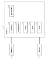
- the distance image camera C captures a distance image with a pixel value as a distance value.
- the range image camera C may be of a type that measures a distance from a round trip time when an infrared laser is projected onto a target, and may be any type of imaging device.
- the range image camera C has a function of shooting a range image at a fixed time interval or at a timing when a shooting instruction is received, and transmitting the range image to the monitoring server 10 described later.
- the function of the monitoring server 10 can be mounted on the range image camera C. That is, the function of the monitoring server 10 may be realized by an information processing device mounted on the range image camera C.
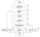
- the detection unit 13 follows the detected vertex and the center of gravity of the person, detects the position and orientation of the person P in the distance image, and detects the state of the person P (step in FIG. 5). S4).
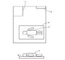
- the detection unit 13 detects the position of the person P in the room R.
- an example of the distance image of the room R is shown in the upper diagram of FIG.
- a bed B, a toilet T, and a door D are installed in a room R, and the position of the person P is detected according to the positional relationship between the installed object and the person P.
- the detection unit 13 performs the detection of the state of the person P described above for each room R. Therefore, the detection unit 13 notifies the identification unit 14 of the identification information of each room R in association with the state of the detected person P.
- the specifying unit 14 Specify the detection status of At this time, as the detection state of the room R to be specified, a plurality of detection states are set in advance, and the specifying unit 14 specifies which of the detection states is the detection state.
- the detection states set in advance include a detection state according to the state of the person P and a detection state according to the state of the device as described below.
- the specifying unit 14 specifies the detection state of each room R according to the state of the device and the state of the person P notified from the device detection unit 11 and the detection unit 13. For example, when the identification unit 14 receives the notification of the “detection target state” such that the person P in the room R is standing on the bed B, the state of the room R is set as the “alert state (detection)”. Identify. When the specifying unit 14 receives a notification that the person P in the room R is lying on the bed B, the specifying unit 14 specifies the state of the room R as the “occupied (bed)”.
- the specifying unit 14 notifies the output unit 15 of the detection state of each room R specified as described above.
- the identification unit 14 notifies the output unit of information on the identified detection state in association with the identification information of the room R.
- the process of specifying the detection state of the room R by the specifying unit 14 described above is an example, and is not limited to specifying the detection state described above. Further, the specifying unit 14 may specify the detection state of the room R by another method.
- the room information is displayed in a color corresponding to the detection state (Yes in step S2 in FIG. 5, step S8).
- the room information of each room P is displayed in a filled pattern.
- the room information may be displayed in a different color, or may be displayed in a different display form. Good.
- the states of a plurality of rooms P are collectively displayed on the display screen of the monitoring terminal 30. That is, for each room P, the state of the device used for monitoring (error, not connected (normal system), not connected (abnormal system)) and the state of person P (detection, occupancy (bed), occupancy (occupancy)) , Occupancy (toilet), and absence) are displayed according to each state. For this reason, a supervisor or a caregiver can grasp a plurality of situations in a plurality of rooms at a glance.
- the room information is displayed in the color of “detection” corresponding to the state, so that the monitor or the caregiver can The situation can be quickly grasped, and prompt and appropriate measures can be taken, such as going to the room R for nursing care. Further, when a state in which the equipment installed in the room R is out of order is detected, the room information is displayed in the color of “error” corresponding to the state, so that the monitor or the caregiver can promptly. By grasping such a situation, prompt and appropriate measures such as requesting repair can be taken.
- Non-transitory computer readable media include various types of tangible storage media. Examples of non-transitory computer-readable media are magnetic recording media (eg, flexible disk, magnetic tape, hard disk drive), magneto-optical recording media (eg, magneto-optical disk), CD-ROM (Read Only Memory), CD-R, CD-R / W, semiconductor memory (for example, mask ROM, PROM (Programmable @ ROM), EPROM (Erasable @ PROM), flash ROM, RAM (Random @ Access @ Memory)).
- the program may be supplied to the computer by various types of transitory computer readable media. Examples of transitory computer readable media include electrical signals, optical signals, and electromagnetic waves. Transitory computer readable media can provide the program to a computer via a wired communication line such as an electric wire and an optical fiber, or a wireless communication line.
- Reference Signs List 10 monitoring server 11 device detection unit 12 distance image acquisition unit 13 detection unit 14 specifying unit 15 output unit 16 reference information storage unit 30 monitoring terminal B bed C distance image camera P person U user
Landscapes
- Physics & Mathematics (AREA)
- General Physics & Mathematics (AREA)
- Engineering & Computer Science (AREA)
- Emergency Management (AREA)
- Health & Medical Sciences (AREA)
- Life Sciences & Earth Sciences (AREA)
- Business, Economics & Management (AREA)
- Molecular Biology (AREA)
- Public Health (AREA)
- Biomedical Technology (AREA)
- Heart & Thoracic Surgery (AREA)
- Medical Informatics (AREA)
- Biophysics (AREA)
- Surgery (AREA)
- Animal Behavior & Ethology (AREA)
- General Health & Medical Sciences (AREA)
- Pathology (AREA)
- Veterinary Medicine (AREA)
- Computer Vision & Pattern Recognition (AREA)
- Theoretical Computer Science (AREA)
- Invalid Beds And Related Equipment (AREA)
- Measuring And Recording Apparatus For Diagnosis (AREA)
- Image Analysis (AREA)
- Alarm Systems (AREA)
Applications Claiming Priority (2)
| Application Number | Priority Date | Filing Date | Title |
|---|---|---|---|
| JP2018-140724 | 2018-07-26 | ||
| JP2018140724A JP2020014738A (ja) | 2018-07-26 | 2018-07-26 | 情報処理装置 |
Publications (1)
| Publication Number | Publication Date |
|---|---|
| WO2020021897A1 true WO2020021897A1 (ja) | 2020-01-30 |
Family
ID=69181037
Family Applications (1)
| Application Number | Title | Priority Date | Filing Date |
|---|---|---|---|
| PCT/JP2019/023349 Ceased WO2020021897A1 (ja) | 2018-07-26 | 2019-06-12 | 情報処理装置 |
Country Status (2)
| Country | Link |
|---|---|
| JP (1) | JP2020014738A (https=) |
| WO (1) | WO2020021897A1 (https=) |
Citations (5)
| Publication number | Priority date | Publication date | Assignee | Title |
|---|---|---|---|---|
| JP2004049309A (ja) * | 2002-07-16 | 2004-02-19 | National Trust:Kk | 被看護・被介護者の監視システム |
| JP2012030042A (ja) * | 2010-06-30 | 2012-02-16 | Panasonic Electric Works Co Ltd | 監視装置、プログラム |
| JP2012519547A (ja) * | 2009-03-04 | 2012-08-30 | マシモ・コーポレイション | 医療監視システム |
| JP2013066704A (ja) * | 2011-09-21 | 2013-04-18 | General Electric Co <Ge> | 乳児群の生理学的状態を監視するシステムおよび方法 |
| US20150302539A1 (en) * | 2014-04-16 | 2015-10-22 | Vios Medical Singapore PTE LTD | Patient care and health information management systems and methods |
-
2018
- 2018-07-26 JP JP2018140724A patent/JP2020014738A/ja active Pending
-
2019
- 2019-06-12 WO PCT/JP2019/023349 patent/WO2020021897A1/ja not_active Ceased
Patent Citations (5)
| Publication number | Priority date | Publication date | Assignee | Title |
|---|---|---|---|---|
| JP2004049309A (ja) * | 2002-07-16 | 2004-02-19 | National Trust:Kk | 被看護・被介護者の監視システム |
| JP2012519547A (ja) * | 2009-03-04 | 2012-08-30 | マシモ・コーポレイション | 医療監視システム |
| JP2012030042A (ja) * | 2010-06-30 | 2012-02-16 | Panasonic Electric Works Co Ltd | 監視装置、プログラム |
| JP2013066704A (ja) * | 2011-09-21 | 2013-04-18 | General Electric Co <Ge> | 乳児群の生理学的状態を監視するシステムおよび方法 |
| US20150302539A1 (en) * | 2014-04-16 | 2015-10-22 | Vios Medical Singapore PTE LTD | Patient care and health information management systems and methods |
Also Published As
| Publication number | Publication date |
|---|---|
| JP2020014738A (ja) | 2020-01-30 |
Similar Documents
| Publication | Publication Date | Title |
|---|---|---|
| US10102730B2 (en) | Monitoring apparatus for monitoring a targets exposure to danger | |
| JP5858940B2 (ja) | 離床監視システム | |
| EP3468180A1 (en) | Display control device, display control system, display control method, display control program, and recording medium | |
| JP6579411B1 (ja) | 介護設備又は病院用の監視システム及び監視方法 | |
| US20190046080A1 (en) | Monitoring target person monitoring device, method, and system | |
| JP2023035448A (ja) | 監視装置、監視システムおよび監視方法 | |
| WO2019073735A1 (ja) | 被監視者監視支援システムおよび被監視者監視支援方法 | |
| WO2020031850A1 (ja) | 情報処理装置 | |
| WO2019163561A1 (ja) | 情報処理装置 | |
| JP2020140418A (ja) | 携帯端末の制御プログラム、携帯端末および見守りシステム | |
| WO2019240196A1 (ja) | 情報処理装置 | |
| JP2020052826A (ja) | 情報提供装置、情報提供システム、情報提供方法、及びプログラム | |
| US11513007B2 (en) | Notification control device, notification control system, and notification control method | |
| WO2019031010A1 (ja) | 睡眠状態検出装置および該方法ならびに被監視者監視支援システム | |
| WO2020021897A1 (ja) | 情報処理装置 | |
| JP7232497B2 (ja) | 情報処理装置 | |
| JP2022126071A (ja) | 画像処理方法 | |
| WO2019240197A1 (ja) | 情報処理装置 | |
| JP6807247B2 (ja) | 監視システム、及び監視方法 | |
| WO2020145145A1 (ja) | 情報処理装置 | |
| JP7607319B2 (ja) | 画像処理方法 | |
| JP7818460B2 (ja) | ナースコールシステム | |
| JP7615705B2 (ja) | 情報処理装置、見守りシステム、制御プログラム、および制御方法 | |
| JP7338268B2 (ja) | 見守りシステムおよび見守り方法 | |
| JP3215201U (ja) | 監視装置 |
Legal Events
| Date | Code | Title | Description |
|---|---|---|---|
| 121 | Ep: the epo has been informed by wipo that ep was designated in this application |
Ref document number: 19839825 Country of ref document: EP Kind code of ref document: A1 |
|
| NENP | Non-entry into the national phase |
Ref country code: DE |
|
| 122 | Ep: pct application non-entry in european phase |
Ref document number: 19839825 Country of ref document: EP Kind code of ref document: A1 |