WO2020021738A1 - 位置検出システム、算出装置、プログラムおよび位置検出方法 - Google Patents
位置検出システム、算出装置、プログラムおよび位置検出方法 Download PDFInfo
- Publication number
- WO2020021738A1 WO2020021738A1 PCT/JP2019/003506 JP2019003506W WO2020021738A1 WO 2020021738 A1 WO2020021738 A1 WO 2020021738A1 JP 2019003506 W JP2019003506 W JP 2019003506W WO 2020021738 A1 WO2020021738 A1 WO 2020021738A1
- Authority
- WO
- WIPO (PCT)
- Prior art keywords
- communication device
- fixed communication
- communication devices
- mobile communication
- fixed
- Prior art date
- Legal status (The legal status is an assumption and is not a legal conclusion. Google has not performed a legal analysis and makes no representation as to the accuracy of the status listed.)
- Ceased
Links
Images











Classifications
-
- G—PHYSICS
- G01—MEASURING; TESTING
- G01S—RADIO DIRECTION-FINDING; RADIO NAVIGATION; DETERMINING DISTANCE OR VELOCITY BY USE OF RADIO WAVES; LOCATING OR PRESENCE-DETECTING BY USE OF THE REFLECTION OR RERADIATION OF RADIO WAVES; ANALOGOUS ARRANGEMENTS USING OTHER WAVES
- G01S5/00—Position-fixing by co-ordinating two or more direction or position line determinations; Position-fixing by co-ordinating two or more distance determinations
- G01S5/02—Position-fixing by co-ordinating two or more direction or position line determinations; Position-fixing by co-ordinating two or more distance determinations using radio waves
- G01S5/14—Determining absolute distances from a plurality of spaced points of known location
-
- H—ELECTRICITY
- H04—ELECTRIC COMMUNICATION TECHNIQUE
- H04W—WIRELESS COMMUNICATION NETWORKS
- H04W64/00—Locating users or terminals or network equipment for network management purposes, e.g. mobility management
Definitions
- the present invention relates to a position detection system, a calculation device, a program, and a position detection method.
- the position of the moving point is calculated based on the radio wave intensity of the beacon signal transmitted from the transmitter (for example, LQI (Link Quality Indicator) or RSSI (Received Signal Strength Indication) or the like).
- LQI Link Quality Indicator
- RSSI Receiveived Signal Strength Indication
- three-point surveying is performed using the radio wave intensity of three beacon signals wirelessly communicated between three fixed communication devices installed on a wall or a ceiling and the information processing device.
- the position of the information processing device is calculated by the method.
- Patent Document 1 describes a method of estimating a position of a forklift moving in an area by attaching RFID tags to a plurality of columns provided at intersections of a grid-shaped area.
- Patent Literature 2 describes a position detection system including a wireless device, a plurality of fixed reception devices, and a position detection device. In the position detection system of Patent Literature 2, the position detection device searches a database storing the correspondence between the location and the intensity based on the radio wave intensity of each fixed reception device, and outputs a location corresponding to the intensity stored in the database.
- the upper three fixed communication devices are selected from the one with the stronger radio wave intensity at the reception point of the beacon signal.
- there are various obstacles in a space such as indoors or underground unlike the outdoors. For this reason, among a plurality of fixed communication devices installed on a wall, a ceiling, or the like, the radio wave intensity of a signal transmitted / received by a multipath or the like is abnormally increased, or the radio wave intensity of a transmitted / received signal is abnormally weakened. Fixed communication devices can occur.
- the present invention has been made in view of the above, and has as its object to provide a position detection system, a calculation device, a program, and a position detection method for accurately detecting the position of a mobile communication device.
- a position detection system includes a plurality of fixed communication devices arranged at predetermined positions, and a reference signal output at a predetermined transmission power.
- a mobile communication device that wirelessly communicates with each of the plurality of fixed communication devices, and a radio wave intensity at a reception point of the reference signal wirelessly communicated with the mobile communication device from among the plurality of fixed communication devices, is set in advance.
- a specifying unit that specifies a plurality of valid fixed communication devices excluding a fixed communication device that is out of a predetermined range; positions of the plurality of valid fixed communication devices; and the plurality of valid fixed communication devices
- a position calculating unit that calculates the position of the mobile communication device based on the radio field intensity at the reception points of the plurality of reference signals wirelessly communicated between the mobile communication device and the mobile communication device.
- the position of the mobile communication device can be accurately detected.
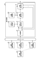
- FIG. 1 is a diagram showing a position detection system.
- FIG. 2 is a diagram showing the transmission power at the transmission point of the reference signal and the radio wave intensity at the reception point.
- FIG. 3 is a diagram showing a plurality of partial regions obtained by dividing the target region.
- FIG. 4 is a diagram illustrating a plurality of reference patterns corresponding one-to-one to a plurality of partial regions.
- FIG. 5 is a diagram illustrating a plurality of transmission paths between a reference communication device and a plurality of fixed communication devices.
- FIG. 6 is a diagram illustrating a functional configuration of the calculation device according to the first embodiment, together with a mobile communication device and a plurality of fixed communication devices.
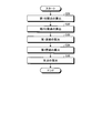
- FIG. 7 is a flowchart illustrating a flow of a process of the calculation device according to the first embodiment.
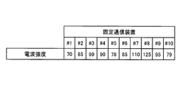
- FIG. 8 is a diagram illustrating an example of the measurement patterns collected in S11.
- FIG. 9 is a diagram illustrating an example of the measurement pattern quantized in S12.
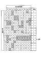
- FIG. 10 is a diagram illustrating an example of a comparison result between the plurality of reference patterns and the measurement pattern in S13.
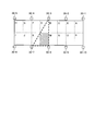
- FIG. 11 is a diagram illustrating an example of three fixed communication devices surrounding a partial area selected in S14.
- FIG. 12 is a diagram illustrating an example of the radio wave intensity at the reception point of the reference signal acquired in S15.
- FIG. 13 is a diagram illustrating an example of the position of the fixed communication device acquired in S16.
- FIG. 14 is a diagram illustrating an example of a set previously associated with a partial area.
- FIG. 15 is a diagram illustrating an example of a plurality of sets including three fixed communication devices surrounding a partial area.
- FIG. 16 is a diagram illustrating an example of a plurality of sets associated with a partial region.
- FIG. 17 is a flowchart illustrating a flow of a process of calculating the position of the mobile communication device.
- FIG. 18 is a diagram illustrating an example of a method for calculating the position of the mobile communication device.
- FIG. 19 is a diagram illustrating a functional configuration of a calculation device according to the second embodiment, together with a mobile communication device and a plurality of fixed communication devices.
- FIG. 20 is a diagram illustrating the relationship between the position of the mobile communication device and the radio wave intensity at the reception point of the reference signal.
- FIG. 21 is a flowchart illustrating a flow of a process of the calculation device according to the second embodiment.
- FIG. 22 is a diagram illustrating a waveform of a short burst signal at a transmission point.
- FIG. 23 is a flowchart illustrating a flow of a first process of the calculation device according to the third embodiment.
- FIG. 24 is a flowchart illustrating a flow of a second process of the calculation device according to the third embodiment.
- FIG. 25 is a diagram illustrating a hardware configuration of the information processing apparatus.
- the position detection system 10 accurately detects the position of the mobile communication device 20 that moves indoors or underground.
- FIG. 1 is a diagram illustrating a position detection system 10 according to the first embodiment.
- the position detection system 10 according to the first embodiment includes a mobile communication device 20, a plurality of fixed communication devices 30, and a calculation device 40.
- the mobile communication device 20 is an information processing terminal carried by a user.
- the mobile communication device 20 has a communication function, an input function, and an output function such as audio output and image display.
- the mobile communication device 20 may be any device such as a notebook computer, a smartphone, a tablet terminal, a mobile phone, or a dedicated information terminal as long as it has such a function.
- the plurality of fixed communication devices 30 are arranged at different predetermined positions indoors or underground.
- the plurality of fixed communication devices 30 are arranged so as to surround a target area for detecting the position of the mobile communication device 20.
- the plurality of fixed communication devices 30 are installed on a ceiling, a wall, a pillar, or the like, for example, indoor or underground.
- the fixed communication device 30 is an information processing terminal capable of wireless communication with the mobile communication device 20.
- the fixed communication device 30 is, for example, a wireless router device such as Wi-Fi (registered trademark) or Bluetooth (registered trademark).
- Wi-Fi registered trademark
- Bluetooth registered trademark
- the mobile communication device 20 can access a server on the Internet via any one of the plurality of fixed communication devices 30.
- the calculation device 40 is an information processing device connected to the mobile communication device 20 and the plurality of fixed communication devices 30 via a network.
- the calculation device 40 may be a general computer or server.
- the calculation device 40 may be a single computer, or may be configured by a plurality of computers such as a cloud system.
- the ⁇ calculation device 40 may be provided in the vicinity of the target region or may be provided in a place remote from the target region. Further, the calculation device 40 may be realized in the mobile communication device 20.
- the calculation device 40 is connected to the mobile communication device 20 or the plurality of fixed communication devices 30 via a network, acquires necessary information from the mobile communication device 20 or the plurality of fixed communication devices 30, and determines the position of the mobile communication device 20. Is calculated.
- the position detection system 10 detects the position of the mobile communication device 20 in the target area, and displays the detected position on, for example, a display unit of the mobile communication device 20 or the like. Thereby, the user can recognize his / her position in the target area.
- FIG. 2 is a diagram showing the transmission power at the transmission point of the reference signal and the radio field intensity at the reception point.
- the mobile communication device 20 wirelessly communicates a reference signal output at a predetermined transmission power with each of the plurality of fixed communication devices 30.
- the mobile communication device 20 transmits a reference signal to each of the plurality of fixed communication devices 30 at every first interval. Then, in the present embodiment, each of the plurality of fixed communication devices 30 receives the reference signal transmitted from the mobile communication device 20.
- each of the plurality of fixed communication devices 30 may transmit the reference signal to the mobile communication device 20 at every first interval.
- the mobile communication device 20 receives a plurality of reference signals transmitted from each of the plurality of fixed communication devices 30.
- the plurality of fixed communication devices 30 transmit the reference signals at different times, for example, so that the transmitted reference signals do not interfere with each other.
- the transmission power of the reference signal is a predetermined value as shown in FIG.
- the radio wave intensity at the reception point of the reference signal differs depending on the transmission path between the mobile communication device 20 and the fixed communication device 30.
- the radio field intensity at the reception point of the reference signal decreases as the distance between the mobile communication device 20 and the fixed communication device 30 increases. Therefore, when the mobile communication device 20 moves in a direction away from the fixed communication device 30, the radio field intensity at the reception point of the reference signal wirelessly communicated between the fixed communication device 30 and the mobile communication device 20 is: As shown in FIG. 2B, the size gradually decreases. Conversely, when the mobile communication device 20 moves in a direction approaching the fixed communication device 30, the radio field intensity at the reception point of the reference signal wirelessly communicated between the fixed communication device 30 and the mobile communication device 20 is as shown in FIG. As shown in FIG. 2 (C), it gradually increases.
- FIG. 3 is a diagram showing a plurality of partial regions obtained by dividing the target region.
- a plurality of partial regions obtained by dividing the target region are set, for example, as shown by APs separated by dotted lines in FIG.
- a plurality of fixed communication devices 30 are arranged around the target area. For example, in the example of FIG. 3, ten fixed communication devices 30 (30-1 to 30-10) are arranged so as to surround the target area. The plurality of fixed communication devices 30 are arranged so that there are at least three fixed communication devices 30 surrounding all the partial regions.
- FIG. 4 is a diagram showing a plurality of reference patterns corresponding one-to-one to a plurality of partial regions.
- FIG. 5 shows a case where the reference communication device 50 is arranged at the center of the partial area (N) and the plurality of fixed communication devices 30 (30-1 to 30-10) are connected.
- FIG. 3 is a diagram illustrating a transmission path.
- a plurality of reference patterns are generated in advance before the process of detecting the position of the mobile communication device 20.
- the plurality of reference patterns correspond one-to-one to the plurality of partial regions.
- 16 reference patterns corresponding to the partial areas A to P on a one-to-one basis are generated in advance.
- Each of the plurality of reference patterns represents the radio field intensity at the receiving point of the plurality of reference signals wirelessly communicated between the plurality of fixed communication devices 30 and the reference communicator 50 arranged in the corresponding partial area.
- the reference pattern indicates the radio field intensity at the reception point of the reference signal for each fixed communication device 30 (# 1 to # 10).
- the reference pattern represents the radio wave intensity quantized in a predetermined unit.
- each of the plurality of reference patterns represents the radio field intensity of the plurality of reference signals received by the plurality of fixed communication devices 30 and transmitted from the reference communicator 50 arranged in the corresponding partial area.
- each of the plurality of reference patterns may represent the radio wave intensity of the plurality of reference signals transmitted from the plurality of fixed communication devices 30 and received by the reference communication device 50 arranged in the corresponding partial area. .
- a predetermined position in the partial area (N) for example, the partial area (N)
- the radio wave intensity at the reception points of the plurality of reference signals wirelessly communicated between the reference communicator 50 and the plurality of fixed communication devices 30 is acquired.
- the administrator of the position detection system 10 generates a reference pattern corresponding to the partial area based on the radio wave intensities at the reception points of the plurality of reference signals thus obtained.
- the administrator of the position detection system 10 may set the reference pattern based on the actually measured radio field intensity, or may generate the reference pattern based on the radio field intensity calculated by a simulation or the like.
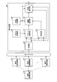
- FIG. 6 is a diagram illustrating a functional configuration of the calculation device 40 according to the first embodiment, together with the mobile communication device 20 and the plurality of fixed communication devices 30.
- the calculation device 40 is connected to a plurality of fixed communication devices 30 via a network.
- the network between the calculation device 40 and the plurality of fixed communication devices 30 may be wireless or wired.
- the calculation device 40 includes a pattern storage unit 62, a position storage unit 64, a collection unit 70, a pattern selection unit 72, a device selection unit 74, and a position calculation unit 76.
- the pattern storage unit 62 stores a plurality of reference patterns generated in advance. For example, a plurality of reference patterns are registered in the pattern storage unit 62 by an administrator of the position detection system 10.
- the plurality of reference patterns represent values obtained by quantizing the radio wave intensity at the reception points of the plurality of reference signals in predetermined units, as shown in FIG.
- the position storage unit 64 stores the position of each of the plurality of fixed communication devices 30.
- Each position of the plurality of fixed communication devices 30 is represented by, for example, coordinates based on a predetermined position.
- the position of the fixed communication device 30 is measured by an administrator of the position detection system 10 at the time of installation, for example, and registered in the position storage unit 64 in advance by the administrator.
- the collection unit 70 collects the radio wave intensity at the reception points of the plurality of reference signals wirelessly communicated between the plurality of fixed communication devices 30 and the mobile communication device 20.
- the mobile communication device 20 transmits a reference signal
- each of the plurality of fixed communication devices 30 receives the reference signal.
- the collection unit 70 acquires the radio field intensity of the plurality of reference signals received by the plurality of fixed communication devices 30.
- each of the plurality of fixed communication devices 30 may transmit the reference signal, and the mobile communication device 20 may receive the plurality of reference signals.
- the collection unit 70 acquires the radio field intensity of the plurality of reference signals received by the mobile communication device 20.
- the ⁇ ⁇ pattern selection unit 72 acquires the radio wave intensity at the reception points of the plurality of reference signals collected by the collection unit 70 and wirelessly communicated between the plurality of fixed communication devices 30 and the mobile communication device 20. Then, the pattern selecting unit 72 receives reception points of the plurality of reference signals wirelessly communicated between the plurality of fixed communication devices 30 and the mobile communication device 20 from among the plurality of reference patterns stored in the pattern storage unit 62. One reference pattern closest to the measurement pattern representing the radio field intensity at is selected.
- the pattern selection unit 72 determines whether the plurality of fixed communication devices 30 have received the plurality of reference signals. Then, a measurement pattern representing the radio field intensity is compared with each of the plurality of reference patterns to select one reference pattern. Further, when each of the plurality of fixed communication devices 30 transmits a reference signal and the mobile communication device 20 receives the plurality of reference signals, a measurement pattern indicating the radio field intensity of the plurality of reference signals received by the mobile communication device 20 is provided. , Is compared with each of the plurality of reference patterns to select one reference pattern.
- the pattern selection unit 72 quantifies the radio wave intensity at the reception point of the plurality of reference signals wirelessly communicated between the plurality of fixed communication devices 30 and the mobile communication device 20 in a predetermined unit. To generate a measurement pattern. Then, the pattern selection unit 72 compares the measurement pattern representing the value of the radio field intensity at the reception point of the plurality of quantized reference signals with each of the plurality of reference patterns, and determines one reference pattern closest to the measurement pattern. Select
- the device selecting unit 74 selects three or more fixed communication devices 30 from the plurality of fixed communication devices 30 based on the partial area corresponding to the selected reference pattern. For example, the device selection unit 74 selects three or more fixed communication devices 30 arranged at positions surrounding a partial region corresponding to the selected reference pattern. Further, for example, a set including three or more fixed communication devices 30 may be associated in advance with each of the plurality of reference patterns. In this case, the device selecting unit 74 selects three or more fixed communication devices 30 included in the set linked to the selected reference pattern.
- the position calculation unit 76 obtains the respective positions of the three or more fixed communication devices 30 selected by the device selection unit 74 from the position storage unit 64.
- the position calculating unit 76 collects the radio field intensity at the receiving points of the three or more reference signals wirelessly communicated between the three or more fixed communication devices 30 and the mobile communication device 20 selected by the device selecting unit 74. Obtained from the unit 70. Then, the position calculation unit 76 calculates the positions of the selected three or more fixed communication devices 30 and the three or more standards that are wirelessly communicated between the selected three or more fixed communication devices 30 and the mobile communication device 20.
- the position of the mobile communication device 20 is calculated based on the radio wave intensity at the signal receiving point.
- the position calculating unit 76 calculates the position of the mobile communication device 20 by a three-point positioning method or the like. An example of a specific method of calculating the position by the position calculating unit 76 will be further described with reference to FIGS.
- the position calculator 76 outputs the calculated position.
- the position calculation unit 76 may cause the display unit of the mobile communication device 20 to display the calculated position. Further, the position calculation unit 76 may transmit the calculated position to another device via a network.
- FIG. 7 is a flowchart showing the flow of processing of the calculation device 40 according to the first embodiment.
- FIGS. 8 to 13 are diagrams referred to when explaining the flowchart shown in FIG.
- the calculation device 40 executes the process shown in FIG. 7 every time a reference signal is transmitted and received between the plurality of fixed communication devices 30 and the mobile communication device 20.
- the collection unit 70 collects radio wave intensities at reception points of a plurality of reference signals wirelessly communicated between the plurality of fixed communication devices 30 and the mobile communication device 20. For example, the collection unit 70 collects the radio field intensity at the reception point of the reference signal for each fixed communication device 30 (# 1 to # 10) as shown in FIG.
- the pattern selection unit 72 quantizes the radio wave intensity at the reception points of the plurality of reference signals wirelessly communicated between the plurality of fixed communication devices 30 and the mobile communication device 20 in predetermined units. Generate a measurement pattern. For example, the pattern selection unit 72 generates a measurement pattern obtained by quantizing the radio wave intensity at the reception point of the reference signal for each fixed communication device 30 (# 1 to # 10) as shown in FIG.
- the pattern selection unit 72 selects one reference pattern closest to the measurement pattern from the plurality of reference patterns stored in the pattern storage unit 62. For example, as shown in FIG. 10, the pattern selection unit 72 determines whether or not each of the plurality of reference patterns matches the value included in the measurement pattern for each fixed communication device 30 (# 1 to # 10). I do. Subsequently, the pattern selection unit 72 calculates the number of matching values for each reference pattern. Then, the pattern selection unit 72 selects the reference pattern having the largest number of matching values as the reference pattern closest to the measurement pattern. Note that the pattern selection unit 72 may select one reference pattern closest to the measurement pattern by another comparison method. For example, the pattern selection unit 72 may calculate the distance (norm) between the measurement pattern and the reference pattern, and select the reference pattern having the smallest norm as the reference pattern closest to the measurement pattern.
- ⁇ Pattern selection unit 72 specifies a partial region corresponding to the selected reference pattern. For example, in the example of FIG. 10, the pattern selection unit 72 specifies the partial area (L).
- the device selecting unit 74 selects three or more fixed communication devices 30 from the plurality of fixed communication devices 30 based on the partial area corresponding to the selected reference pattern. For example, the device selecting unit 74 selects the three or more fixed communication devices 30 so that the polygon having the selected three or more fixed communication devices 30 as vertices includes all the partial regions corresponding to the selected reference pattern. I do. For example, in the example of FIG. 11, the device selecting unit 74 determines that the three fixed communication devices 30 (# 3, # 7, # 8) are arranged at positions surrounding the partial area (L) corresponding to the selected reference pattern. ).
- the position calculation unit 76 determines whether or not the three or more fixed communication devices 30 and the mobile communication device 20 selected by the device selection unit 74 have wirelessly communicated with each other at three or more reference signal reception points.
- the radio wave intensity is acquired from the collection unit 70.
- the position calculating unit 76 performs wireless communication between the three selected fixed communication devices 30 (# 3, # 7, # 8) and the mobile communication device 20.
- the radio field intensity at the receiving points of the two reference signals is obtained.
- the position calculation unit 76 acquires the respective positions of the three or more fixed communication devices 30 selected by the device selection unit 74 from the position storage unit 64. For example, as shown in FIG. 13, the position calculation unit 76 acquires three coordinates (x, y) indicating the positions of the three selected fixed communication devices 30 (# 3, # 7, # 8). I do.
- the position calculating unit 76 performs wireless communication between the selected three or more fixed communication devices 30 and the selected three or more fixed communication devices 30 and the mobile communication device 20.
- the position of the mobile communication device 20 is calculated based on the radio wave intensity at the reception points of three or more reference signals.
- the position calculating unit 76 determines the position of the mobile communication device 20 by the three-point positioning method using the positions of the three fixed communication devices 30 (# 3, # 7, # 8) and the radio wave intensities of the three reference signals. calculate.
- An example of a specific method of calculating the position by the position calculating unit 76 will be further described with reference to FIGS.
- the position calculation unit 76 outputs the calculated position.
- FIG. 14 is a diagram showing an example of a set previously associated with a partial area.
- Each of the plurality of reference patterns may be associated in advance with a set including three or more fixed communication devices 30.
- the device selecting unit 74 selects three or more fixed communication devices 30 included in the set linked to the selected reference pattern.
- FIG. 15 is a diagram showing an example of a plurality of sets including three fixed communication devices 30 surrounding a partial area.
- the device selection unit 74 may select a plurality of sets of three or more fixed communication devices 30 surrounding a partial region corresponding to the selected reference pattern.
- the device selection unit 74 includes three fixed communication devices 30 (# 3, # 7, # 8) arranged at positions surrounding a partial region corresponding to the selected reference pattern. A first set and a second set including three fixed communication devices 30 (# 4, # 7, # 9) are selected.
- the position calculation unit 76 calculates a candidate position of the mobile communication device 20 for each selected pair. Then, the position calculation unit 76 determines the average value or the median of the candidate positions calculated for each pair as the position of the mobile communication device 20.
- FIG. 16 is a diagram showing an example of a plurality of sets associated with a partial area.
- each of the plurality of reference patterns may be associated with a plurality of sets including three or more fixed communication devices 30.
- the device selection unit 74 selects a plurality of sets associated with the selected reference pattern.
- position calculating section 76 calculates a candidate position of mobile communication device 20 for each selected pair, and determines the average or median of the candidate positions calculated for each pair as the position of mobile communication device 20.
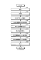
- FIG. 17 is a flowchart showing the flow of the process of calculating the position of the mobile communication device 20.
- FIG. 18 is a diagram for explaining an example of a method of calculating the position of the mobile communication device 20 when three fixed communication devices 30 are selected.
- the device selecting unit 74 selects the first fixed communication device 30-1, the second fixed communication device 30-2, and the third fixed communication device 30-3 from the plurality of fixed communication devices 30.
- the position of the first fixed communication device 30-1 is (x 1 , y 1 )
- the position of the second fixed communication device 30-2 is (x 2 , y 2 )
- the position of the third fixed communication device 30-2 is (x 2 , y 2 ).
- the position of the fixed communication device 30-3 is (x 3 , y 3 ).
- the radio field intensity at the reception point of the reference signal wirelessly communicated between the mobile communication device 20 and the first fixed communication device 30-1 is "1”.
- the radio field intensity at the receiving point of the reference signal wirelessly communicated between the mobile communication device 20 and the second fixed communication device 30-2 is "m”.
- the radio field intensity at the receiving point of the reference signal wirelessly communicated between the mobile communication device 20 and the third fixed communication device 30-3 is "n”.
- the position calculation unit 76 calculates the position of the mobile communication device 20 according to, for example, the flowchart shown in FIG.
- a first division point (x a, y a) is calculated.
- the first division point (x a , y a ) is defined by a line connecting the position of the first fixed communication device 30-1 and the position of the second fixed communication device 30-2 with the radio field intensity at the reference signal receiving point. The point is that the image is divided at a ratio corresponding to the size of.
- the position calculation unit 76 calculates the following divisions (1) and (2) to calculate the first division point (x a , y a ).
- the position calculation unit 76 calculates the second division point (x b , y b ) by calculating the following equations (3) and (4).
- the position calculation unit 76 calculates a second straight line 122 connecting the second division point (x b , y b ) and the position of the first fixed communication device 30-1.
- the position calculation unit 76 calculates an intersection ( Gx , Gy ) between the first straight line 121 and the second straight line 122. Then, the position calculating unit 76 outputs the intersection (G x , G y ) as the position of the mobile communication device 20.
- the position calculating unit 76 may directly calculate the intersection (G x , G y ) of the first straight line 121 and the second straight line 122 by the following equation (5).
- the position detection system 10 specifies a partial area where the mobile communication device 20 exists in the target area, and selects three or more fixed communication apparatuses 30 surrounding the partial area.
- the positions of the selected three or more fixed communication devices 30 and the wireless communication between the mobile communication device 20 and the selected three or more fixed communication devices 30 are performed.
- the mobile communication device 20 is calculated based on the radio field intensity at the reception points of three or more reference signals. Thereby, the position detection system 10 according to the first embodiment can accurately detect the position of the mobile communication device 20.
- the position detection system 10 according to the second embodiment has substantially the same function and configuration as the position detection system 10 according to the first embodiment. Regarding the position detection system 10 according to the second embodiment, differences from the first embodiment will be described.
- FIG. 19 is a diagram illustrating a functional configuration of the calculation device 40 according to the second embodiment, together with the mobile communication device 20 and the plurality of fixed communication devices 30.
- the calculation device 40 further includes a specifying unit 92.
- the specifying unit 92 obtains the radio field intensity at the reception point of the plurality of reference signals wirelessly communicated between the plurality of fixed communication devices 30 and the mobile communication device 20 collected by the collection unit 70. Then, the specifying unit 92 determines, from among the plurality of fixed communication devices 30, the fixed communication in which the radio field intensity at the reception point of the reference signal wirelessly communicated with the mobile communication device 20 is out of the predetermined range. A plurality of valid fixed communication devices 30 excluding the device 30 are specified.
- the device selecting unit 74 includes three or more valid fixed communication devices 30 based on the partial area corresponding to the selected reference pattern from among the valid fixed communication devices 30 specified by the specifying unit 92. Select For example, the device selecting unit 74 selects three or more valid fixed communication devices 30 arranged at positions surrounding the partial region corresponding to the selected reference pattern.
- the position calculation unit 76 obtains, from the position storage unit 64, the positions of three or more valid fixed communication devices 30 selected by the device selection unit 74. Further, the position calculating unit 76 calculates the radio field intensity at the receiving points of the three or more reference signals wirelessly communicated between the three or more valid fixed communication devices 30 and the mobile communication device 20 selected by the device selecting unit 74. From the collection unit 70. Then, the position calculating unit 76 performs wireless communication between the selected three or more valid fixed communication devices 30 and the selected three or more valid fixed communication devices 30 and the mobile communication device 20. The position of the mobile communication device 20 is calculated based on the radio wave intensity at the reception points of three or more reference signals.
- FIG. 20 is a diagram illustrating the relationship between the position of the mobile communication device 20 and the radio wave intensity at the reception point of the reference signal wirelessly communicated between the mobile communication device 20 and the fixed communication device 30.
- an area (target area) in which the position of the mobile communication device 20 can be detected is determined in advance. Accordingly, the range of the radio field intensity (the range from the lower limit to the upper limit) at the receiving point of the reference signal wirelessly communicated between the mobile communication device 20 and the fixed communication device 30 is theoretically determined. That is, the radio field intensity at the reception point of the reference signal is theoretically the smallest when the mobile communication device 20 and the fixed communication device 30 are farthest from each other in the target area. In addition, the radio field intensity at the reception point of the reference signal is theoretically the highest when the mobile communication device 20 and the fixed communication device 30 are closest to each other in the target area.
- the administrator of the position detection system 10 adds the margin value to the upper limit value from the value obtained by subtracting the margin value from the lower limit value of the theoretical value range of the radio field intensity at the reception point of the reference signal.
- the range up to the calculated value is set in advance as an effective range.
- the specifying unit 92 determines whether or not the radio wave intensity at the reception point of the plurality of reference signals wirelessly communicated between the plurality of fixed communication devices 30 and the mobile communication device 20 is within a preset effective range. I do.
- the specifying unit 92 sets, from among the plurality of fixed communication devices 30, the fixed communication device 30 in which the radio wave intensity at the reception point of the reference signal wirelessly communicated with the mobile communication device 20 is within the effective range to the valid communication range.
- the fixed communication device 30 is specified.
- the specifying unit 92 excludes the fixed communication device 30 in which the radio wave intensity at the reception point of the reference signal wirelessly communicated with the mobile communication device 20 has an abnormal value due to the influence of multipath or the like.
- the position of the mobile communication device 20 can be calculated.
- the administrator may set a different effective range for each fixed communication device 30.
- the specifying unit 92 obtains a corresponding effective range for each fixed communication device 30, and obtains the obtained effective range and the radio field intensity at the reception point of the reference signal wirelessly communicated with the mobile communication device 20. Compare. Accordingly, the specifying unit 92 can more accurately exclude the fixed communication device 30 having an abnormal value.
- FIG. 21 is a flowchart showing the flow of the process of the calculation device 40 according to the second embodiment.
- the calculation device 40 according to the second embodiment executes the process shown in FIG. 21 every time a reference signal is transmitted and received between the plurality of fixed communication devices 30 and the mobile communication device 20.
- the difference from the first embodiment shown in FIG. 7 is that the process of S41 is executed between S13 and S14.
- the specifying unit 92 sets a plurality of valid fixed communication devices excluding the fixed communication device 30 whose radio field intensity at the reception point of the reference signal is out of the predetermined range from the plurality of fixed communication devices 30.
- the device 30 is specified.
- the device selecting unit 74 selects three or more valid fixed communication devices 30 from the valid fixed communication devices 30 specified in S41 based on the partial area corresponding to the selected reference pattern. I do.
- the position detection system 10 excludes the fixed communication device 30 in which the radio wave intensity at the reception point of the reference signal wirelessly communicated with the mobile communication device 20 has an abnormal value. , The position of the mobile communication device 20 can be calculated.
- the specifying unit 92 may execute the process of S41 before S13.
- the pattern selection unit 72 also compares the plurality of reference patterns with the measurement pattern, excluding the fixed communication device 30 in which the radio wave intensity at the reference signal receiving point has an abnormal value. Good.
- the pattern selection unit 72 determines the radio field intensity at the reception point of the plurality of reference signals wirelessly communicated between the plurality of valid fixed communication devices 30 and the mobile communication device 20 from among the plurality of reference patterns. Is selected as the reference pattern closest to the pattern representing. Accordingly, the calculation device 40 can exclude the measurement value of the fixed communication device 30 in which the radio wave intensity at the reception point of the reference signal becomes abnormal from the stage of selecting the reference pattern.
- the position detection system 10 calculates the position of the mobile communication device 20 excluding the fixed communication device 30 in which the radio field intensity has an abnormal value. Therefore, according to the position detection system 10 according to the second embodiment, even when the fixed communication device 30 whose radio wave intensity of the reference signal is abnormally increased or decreased due to the influence of the multipath or the like is present, the movement is not performed. The position of the communication device 20 can be accurately detected.
- the position detection system 10 according to the third embodiment has substantially the same function and configuration as the position detection system 10 according to the first embodiment.
- differences from the first embodiment will be described. Note that the differences in the third embodiment can be applied to the second embodiment.
- FIG. 22 is a diagram showing a waveform of a short burst signal at a transmission point.
- the mobile communication device 20 wirelessly communicates the short burst signal with each of the plurality of fixed communication devices 30 at every first interval.
- the short burst signal includes a plurality of reference signals output at a predetermined transmission power at predetermined intervals. More specifically, the short burst signal includes N (N is an integer of 2 or more) reference signals output at a predetermined transmission power. In the example of FIG. 22, the short burst signal includes five reference signals. The N reference signals are transmitted at every second interval shorter than the first interval.
- the mobile communication device 20 transmits a short burst signal to each of the plurality of fixed communication devices 30 at every first interval. Then, in the present embodiment, each of the plurality of fixed communication devices 30 receives the short burst signal transmitted from the mobile communication device 20. Further, each of the plurality of fixed communication devices 30 acquires the radio field intensity of each of the N reference signals included in the received short burst signal.
- each of the plurality of fixed communication devices 30 may transmit the short burst signal to the mobile communication device 20 at every first interval.
- the mobile communication device 20 receives a plurality of short burst signals transmitted from each of the plurality of fixed communication devices 30. Further, in this case, for each of the plurality of received short burst signals, the mobile communication device 20 acquires the radio field intensity of each of the N reference signals included in the short burst signal. Further, in this case, the plurality of fixed communication devices 30 transmit the reference signals with a time lag from each other so that the short burst signals transmitted by the respective fixed communication devices 30 do not interfere with each other.
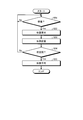
- FIG. 23 is a flowchart illustrating the flow of the first process of the calculation device 40 according to the third embodiment.
- the calculating device 40 according to the third embodiment executes the first process shown in FIG. 23 every time a short burst signal is transmitted and received between the plurality of fixed communication devices 30 and the mobile communication device 20.
- the calculation device 40 determines whether one reference signal included in the short burst signal has been received. If the reference signal has not been received (No in S51), the calculation device 40 waits for the process in S51. When the reference signal has been received (Yes in S51), the calculation device 40 proceeds with the process to S52.
- the calculation device 40 calculates the position of the mobile communication device 20 based on the received reference signal. In this case, the calculation device 40 executes the processing of S11 to S18 in FIG.
- the calculation device 40 stores the calculated position. Subsequently, in S54, the calculation device 40 determines whether the reference signal has been received a predetermined number of times. For example, the calculation device 40 determines whether or not the position has been calculated for all of the N reference signals included in the short burst signal. If the reference signal has not been received a predetermined number of times (No in S54), the calculation device 40 returns the processing to S51, and repeats the processing from S51. If the reference signal has been received a predetermined number of times (Yes in S54), the calculation device 40 proceeds with the process to S55.
- the calculation device 40 calculates an average value of the positions calculated a predetermined number of times. Then, the calculation device 40 outputs the averaged position as the position of the mobile communication device 20. Note that the calculation device 40 may calculate the median value of the position instead of the average value of the position.
- FIG. 24 is a flowchart showing the flow of the second process of the calculation device 40 according to the third embodiment.
- the calculating device 40 according to the third embodiment may execute the second process shown in FIG. 24 every time a short burst signal is transmitted and received between the plurality of fixed communication devices 30 and the mobile communication device 20. Good.
- the calculation device 40 determines whether or not one reference signal included in the short burst signal has been received. When the reference signal has not been received (No in S61), the calculation device 40 waits for the process in S61. If the reference signal has been received (Yes in S61), the calculation device 40 proceeds with the process to S62.
- the calculation device 40 stores the radio wave intensity of the received reference signal.
- the calculation device 40 stores the radio wave intensity for each fixed communication device 30.
- the calculation device 40 determines whether the reference signal has been received a predetermined number of times. For example, the calculation device 40 determines whether or not reference signals have been received for all N reference signals included in the short burst signal. If the reference signal has not been received a predetermined number of times (No in S63), the calculation device 40 returns the processing to S61, and repeats the processing from S61. If the reference signal has been received a predetermined number of times (Yes in S63), the calculation device 40 proceeds with the process to S64.
- the calculation device 40 calculates the average value of the radio wave intensities calculated for the predetermined times. In this case, the calculation device 40 calculates the average value of the radio wave intensity for each fixed communication device 30. Note that the calculation device 40 may calculate the median value of the radio field intensity instead of the average value of the radio field intensity.
- the calculation device 40 calculates the position of the mobile communication device 20 based on the average value of the radio wave intensity for each fixed communication device 30.
- the calculation device 40 executes the processing of S11 to S18 in FIG. Then, the calculation device 40 outputs the calculated position as the position of the mobile communication device 20.
- the position detection system 10 calculates the position of the mobile communication device 20 using the short burst signal.
- the position detection system 10 according to the third embodiment even if the transmission power or the reception sensitivity is instantaneously disturbed, the variation in the detected position is reduced, and the position of the mobile communication device 20 is reduced. Can be accurately detected.
- FIG. 25 is a diagram illustrating a hardware configuration of the information processing apparatus 200.
- the mobile communication device 20, the fixed communication device 30, and the calculation device 40 can be realized by, for example, an information processing device 200 having a communication function as illustrated in FIG.
- the information processing device 200 is realized by, for example, a hardware configuration similar to a general computer.
- the information processing apparatus 200 includes a CPU (Central Processing Unit) 202, a ROM (Read Only Memory) 204, a RAM (Random Access Memory) 206, a storage device 208, a wireless communication device 210, and a network interface device 212. Prepare. Each unit is connected by a bus.
- CPU Central Processing Unit
- ROM Read Only Memory
- RAM Random Access Memory
- the CPU 202 executes various processes in cooperation with various programs stored in the ROM 204 or the storage device 208 in advance using a predetermined area of the RAM 206 as a work area, and comprehensively controls the operation of each unit configuring the information processing apparatus 200. .
- the CPU 202 operates the wireless communication device 210 and the network interface device 212 in cooperation with a program stored in the ROM 204 or the storage device 208 in advance.
- the ROM 204 non-rewritably stores programs used for controlling the information processing apparatus 200 and various setting information.
- the RAM 206 is a volatile storage medium such as SDRAM (Synchronous Dynamic Random Access Memory).
- SDRAM Serial Dynamic Random Access Memory
- the RAM 206 functions as a work area of the CPU 202.
- the storage device 208 is a rewritable recording device such as a semiconductor storage medium such as a flash memory or a magnetically or optically recordable storage medium.
- the storage device 208 stores a program used for controlling the information processing device 200.
- the wireless communication device 210 performs wireless communication with another device using Wi-Fi (registered trademark), Bluetooth (registered trademark), or the like. When applied to the mobile communication device 20 and the fixed communication device 30, the wireless communication device 210 transmits and receives a reference signal. Note that the calculation device 40 may not include the wireless communication device 210.
- the network interface device 212 transmits and receives information to and from other devices via the Internet or the like. For example, when applied to the calculation device 40, the network interface device 212 receives the radio field intensity at the reception point of the reference signal from the mobile communication device 20 or the fixed communication device 30. When the mobile communication device 20 is connected to a network such as the Internet via the fixed communication device 30, the mobile communication device 20 may not include the network interface device 212.
- a program executed by the information processing device 200 is stored on a computer connected to a network such as the Internet, for example, and provided by being downloaded via the network.
- the program executed by the information processing device 200 may be provided by being incorporated in a portable storage medium or the like in advance.
- the program executed by the information processing device 200 has a module configuration including a collection module, a pattern selection module, a device selection module, and a position calculation module.
- the CPU 202 reads such a program from a storage medium or the like, and loads each of the modules into the RAM 206 (main storage device).
- the CPU 202 functions as the collection unit 70, the pattern selection unit 72, the device selection unit 74, and the position calculation unit 76 by executing such a program.
- the storage device 208 functions as the pattern storage unit 62 and the position storage unit 64. Note that some or all of the collection unit 70, the pattern selection unit 72, the device selection unit 74, and the position calculation unit 76 may be configured by hardware.
- Position Detection System 20 Mobile Communication Device 30 Fixed Communication Device 30-1 First Fixed Communication Device 30-2 Second Fixed Communication Device 30-3 Third Fixed Communication Device 40 Calculation Device 50 Reference Communication Device 62 Pattern Storage Unit 64 position storage unit 70 collection unit 72 pattern selection unit 74 device selection unit 76 position calculation unit 92 identification unit 121 first straight line 122 second straight line
Landscapes
- Engineering & Computer Science (AREA)
- Computer Networks & Wireless Communication (AREA)
- Signal Processing (AREA)
- Physics & Mathematics (AREA)
- General Physics & Mathematics (AREA)
- Radar, Positioning & Navigation (AREA)
- Remote Sensing (AREA)
- Position Fixing By Use Of Radio Waves (AREA)
- Mobile Radio Communication Systems (AREA)
Abstract
位置検出システムは、位置を精度良く検出する。位置検出システムは、予め定められた位置に配置された複数の固定通信装置と、所定の送信パワーで出力される基準信号を複数の固定通信装置のそれぞれと無線通信する移動通信装置と、複数の固定通信装置の中から、移動通信装置との間で無線通信された基準信号の受信点における電波強度が予め定められた範囲外となっている固定通信装置を除外した複数の有効な固定通信装置を特定する特定部と、複数の有効な固定通信装置の位置、および、複数の有効な固定通信装置と移動通信装置との間で無線通信された複数の基準信号の受信点における電波強度に基づき、移動通信装置の位置を算出する位置算出部と、を備える。
Description
本発明は、位置検出システム、算出装置、プログラムおよび位置検出方法に関する。
近年、衛星電波の届かない屋内または地下等において、ユーザが持ち運んでいる情報処理装置(例えばスマートフォン)の位置を提供する屋内測位サービスが提案されている。屋内および地下等で情報処理装置の位置を検出する方法としては、情報処理装置に備えられたWi-Fi(登録商標)またはBluetooth(登録商標)等による無線通信機能を利用した方法が知られている。
無線通信機能を用いる方法では、送信機から送信されたビーコン信号の電波強度(例えば、LQI(Link Quality Indicator)またはRSSI(Received Signal Strength Indication)等)に基づき、移動点の位置を算出する。具体的には、この方法では、壁や天井等に設置されている3個の固定通信装置と情報処理装置との間で無線通信された3つのビーコン信号の電波強度を用いて、三点測量法により情報処理装置の位置を算出する。
特許文献1には、格子状の領域の交点に設けられた複数の柱にRFIDタグを取り付けて、領域内を移動するフォークリフトの位置を推定する方法が記載されている。特許文献2には、無線装置と、複数の固定受信装置と、位置検出装置とを備える位置検出システムが記載されている。特許文献2の位置検出システムでは、位置検出装置が、固定受信装置毎の電波強度により場所と強度との対応を記憶したデータベースを検索し、データベースに記憶された強度に対応する場所を出力する。
ところで、この方法では、移動点に近い3個の固定通信装置として、ビーコン信号の受信点における電波強度が強い方から上位の3個の固定通信装置を選択する。しかし、屋内または地下等の空間内には、屋外と異なり様々な障害物が存在する。このため、壁や天井等に設置されている複数の固定通信装置の中には、マルチパス等により送受信する信号の電波強度が異常に強まったり、送受信する信号の電波強度が異常に弱まったりする固定通信装置が発生する可能性がある。従って、この方法では、このような送受信する信号の電波強度が異常に強まったり弱まったりした固定通信装置を、移動点に近い3個の固定通信装置の一つに選択した場合、精度良く情報処理装置の位置を検出することができない。
本発明は、上記に鑑みてなされたものであって、移動通信装置の位置を精度良く検出する位置検出システム、算出装置、プログラムおよび位置検出方法を提供することを目的とする。
上述した課題を解決し、目的を達成するために、本発明に係る位置検出システムは、予め定められた位置に配置された複数の固定通信装置と、所定の送信パワーで出力される基準信号を前記複数の固定通信装置のそれぞれと無線通信する移動通信装置と、前記複数の固定通信装置の中から、前記移動通信装置との間で無線通信された前記基準信号の受信点における電波強度が予め定められた範囲外となっている固定通信装置を除外した複数の有効な固定通信装置を特定する特定部と、前記複数の有効な固定通信装置の位置、および、前記複数の有効な固定通信装置と前記移動通信装置との間で無線通信された複数の前記基準信号の受信点における電波強度に基づき、前記移動通信装置の位置を算出する位置算出部と、を備える。
本発明によれば、移動通信装置の位置を精度良く検出することができる。
以下、図面を参照しながら実施形態に係る位置検出システム10について説明する。位置検出システム10は、屋内または地下等を移動する移動通信装置20の位置を精度良く検出する。
(第1実施形態)
図1は、第1実施形態に係る位置検出システム10を示す図である。第1実施形態に係る位置検出システム10は、移動通信装置20と、複数の固定通信装置30と、算出装置40とを備える。
図1は、第1実施形態に係る位置検出システム10を示す図である。第1実施形態に係る位置検出システム10は、移動通信装置20と、複数の固定通信装置30と、算出装置40とを備える。
移動通信装置20は、使用者により持ち運ばれる情報処理端末である。移動通信装置20は、通信機能、入力機能、および音声出力および画像表示等の出力機能を有する。移動通信装置20は、このような機能を有していれば、例えば、ノート型のコンピュータ、スマートフォン、タブレット端末、携帯電話機または専用の情報端末等のどのような装置であってもよい。
複数の固定通信装置30は、屋内または地下等における互いに異なる予め定められた位置に配置される。例えば、複数の固定通信装置30は、移動通信装置20の位置を検出する対象領域を囲むように配置される。複数の固定通信装置30は、例えば屋内または地下等の天井、壁または柱等に設置される。
固定通信装置30は、移動通信装置20と無線通信が可能な情報処理端末である。固定通信装置30は、例えば、Wi-Fi(登録商標)またはBluetooth(登録商標)等の無線ルータ装置である。固定通信装置30が無線ルータ装置である場合、移動通信装置20は、複数の固定通信装置30のうちの何れかを介して、インターネット上のサーバにアクセスすることができる。
算出装置40は、移動通信装置20および複数の固定通信装置30とネットワークを介して接続される情報処理装置である。例えば、算出装置40は、一般的なコンピュータまたはサーバであってよい。また、算出装置40は、1台のコンピュータであってもよいし、クラウドシステムのように複数台のコンピュータにより構成されていてもよい。
算出装置40は、対象領域の近傍に設けられてもよいし、対象領域から離れた場所に設けられてもよい。また、算出装置40は、移動通信装置20内に実現されてもよい。算出装置40は、移動通信装置20または複数の固定通信装置30とネットワークを介して接続され、移動通信装置20または複数の固定通信装置30から必要な情報を取得して、移動通信装置20の位置を算出する。
使用者は、移動通信装置20を保持して、対象領域内を移動する。位置検出システム10は、対象領域内における移動通信装置20の位置を検出し、検出した位置を例えば移動通信装置20の表示部等に表示する。これにより、使用者は、対象領域内における自身の位置を認識することができる。
図2は、基準信号の送信点における送信パワーおよび受信点における電波強度を示す図である。移動通信装置20は、所定の送信パワーで出力される基準信号を複数の固定通信装置30のそれぞれと無線通信する。
本実施形態において、移動通信装置20は、第1間隔毎に、複数の固定通信装置30のそれぞれに基準信号を送信する。そして、本実施形態において、複数の固定通信装置30のそれぞれは、移動通信装置20から送信された基準信号を受信する。
なお、複数の固定通信装置30のそれぞれは、第1間隔毎に、基準信号を移動通信装置20に対して送信してもよい。この場合、移動通信装置20は、複数の固定通信装置30のそれぞれから送信された複数の基準信号を受信する。この場合、複数の固定通信装置30は、送信した基準信号が干渉しないように、例えば互いに時間をずらして基準信号を送信する。
基準信号の送信パワーは、図2(A)に示されるように、所定の値である。これに対して、基準信号の受信点における電波強度は、移動通信装置20と固定通信装置30との間の伝送路によって異なる。
例えば、基準信号の受信点における電波強度は、伝送路中に障害物等が存在しない場合には、移動通信装置20と固定通信装置30との間の距離が長い程、小さくなる。従って、移動通信装置20がある固定通信装置30から離れていく方向に移動する場合、その固定通信装置30と移動通信装置20との間で無線通信された基準信号の受信点における電波強度は、図2の(B)に示されるように、徐々に小さくなる。反対に、移動通信装置20がある固定通信装置30に近づく方向に移動する場合、その固定通信装置30と移動通信装置20との間で無線通信された基準信号の受信点における電波強度は、図2の(C)に示されるように、徐々に大きくなる。
図3は、対象領域を分割した複数の部分領域を示す図である。位置検出システム10では、例えば図3の点線で区切られたA~Pに示されるような、対象領域を分割した複数の部分領域が設定されている。
対象領域の周囲には、複数の固定通信装置30が配置されている。例えば、図3の例では、10個の固定通信装置30(30-1~30-10)が、対象領域を囲むように配置されている。複数の固定通信装置30は、全ての部分領域について、その部分領域を囲む少なくとも3個の固定通信装置30が存在するように配置されている。
図4は、複数の部分領域に一対一に対応する複数の基準パターンを示す図である。図5は、基準通信機50が部分領域(N)の中心に配置されている場合における、基準通信機50と、複数の固定通信装置30(30-1~30-10)との間の複数の伝送路を示す図である。
位置検出システム10では、移動通信装置20の位置を検出する処理に先だって、予め、複数の基準パターンが生成される。複数の基準パターンは、複数の部分領域に一対一に対応する。例えば、図4の例の場合、A~Pの部分領域に一対一で対応する16個の基準パターンが予め生成される。
複数の基準パターンのそれぞれは、複数の固定通信装置30と対応する部分領域に配置された基準通信機50との間で無線通信された複数の基準信号の、受信点における電波強度を表す。図4の例では、基準パターンは、固定通信装置30(♯1~♯10)毎の基準信号の受信点における電波強度を表す。なお、図4の例では、基準パターンは、所定単位で量子化した電波強度を表す。
例えば、複数の基準パターンのそれぞれは、複数の固定通信装置30が受信した、対応する部分領域に配置された基準通信機50から送信された複数の基準信号の電波強度を表す。また、例えば、複数の基準パターンのそれぞれは、対応する部分領域に配置された基準通信機50が受信した、複数の固定通信装置30から送信された複数の基準信号の電波強度を表してもよい。
例えば、図5に示すように、位置検出システム10の管理者は、部分領域(N)に対応する基準パターンを生成する場合、部分領域(N)内の所定の位置(例えば部分領域(N)の中心)に基準通信機50を配置した場合における、基準通信機50と複数の固定通信装置30との間で無線通信された、複数の基準信号の受信点における電波強度を取得する。そして、位置検出システム10の管理者は、このように取得した複数の基準信号の受信点における電波強度に基づき、その部分領域に対応する基準パターンを生成する。なお、位置検出システム10の管理者は、実測した電波強度により基準パターンを設定してもよいし、シミュレーション等により算出した電波強度により基準パターンを生成してもよい。
図6は、第1実施形態に係る算出装置40の機能構成を、移動通信装置20および複数の固定通信装置30とともに示す図である。算出装置40は、ネットワークを介して複数の固定通信装置30と接続される。算出装置40と複数の固定通信装置30との間のネットワークは、無線であっても有線であってもよい。
算出装置40は、パターン記憶部62と、位置記憶部64と、収集部70と、パターン選択部72と、装置選択部74と、位置算出部76とを有する。
パターン記憶部62は、予め生成された複数の基準パターンを記憶する。例えば、複数の基準パターンは、位置検出システム10の管理者により、パターン記憶部62に登録される。
なお、本実施形態においては、複数の基準パターンは、図4に示したように、複数の基準信号の受信点における電波強度を所定単位で量子化した値を表す。
位置記憶部64は、複数の固定通信装置30のそれぞれの位置を記憶する。複数の固定通信装置30のそれぞれの位置は、例えば、所定の位置を基準とした座標により表される。固定通信装置30の位置は、例えば、設置時において位置検出システム10の管理者により測定され、管理者により位置記憶部64に予め登録される。
収集部70は、複数の固定通信装置30と移動通信装置20との間で無線通信された、複数の基準信号の受信点における電波強度を収集する。本実施形態においては、移動通信装置20が基準信号を送信し、複数の固定通信装置30のそれぞれが基準信号を受信する。この場合、収集部70は、複数の固定通信装置30が受信した複数の基準信号の電波強度を取得する。なお、複数の固定通信装置30のそれぞれが基準信号を送信し、移動通信装置20が複数の基準信号を受信してもよい。この場合、収集部70は、移動通信装置20が受信した複数の基準信号の電波強度を取得する。
パターン選択部72は、収集部70により収集された、複数の固定通信装置30と移動通信装置20との間で無線通信された、複数の基準信号の受信点における電波強度を取得する。そして、パターン選択部72は、パターン記憶部62に記憶された複数の基準パターンの中から、複数の固定通信装置30と移動通信装置20との間で無線通信された複数の基準信号の受信点における電波強度を表す測定パターンに最も近い1つの基準パターンを選択する。
例えば、移動通信装置20が基準信号を送信し、複数の固定通信装置30のそれぞれが基準信号を受信する場合には、パターン選択部72は、複数の固定通信装置30が受信した複数の基準信号の電波強度を表す測定パターンと、複数の基準パターンのそれぞれとを比較して、1つの基準パターンを選択する。また、複数の固定通信装置30のそれぞれが基準信号を送信し、移動通信装置20が複数の基準信号を受信する場合、移動通信装置20が受信した複数の基準信号の電波強度を表す測定パターンと、複数の基準パターンのそれぞれとを比較して、1つの基準パターンを選択する。
なお、本実施形態においては、パターン選択部72は、複数の固定通信装置30と移動通信装置20との間で無線通信された、複数の基準信号の受信点における電波強度を、所定単位で量子化して測定パターンを生成する。そして、パターン選択部72は、量子化した複数の基準信号の受信点における電波強度の値を表す測定パターンと、複数の基準パターンのそれぞれとを比較して、測定パターンに最も近い1つの基準パターンを選択する。
装置選択部74は、選択された基準パターンに対応する部分領域に基づき、複数の固定通信装置30の中から3以上の固定通信装置30を選択する。例えば、装置選択部74は、選択された基準パターンに対応する部分領域を囲む位置に配置された3以上の固定通信装置30を選択する。また、例えば、複数の基準パターンのそれぞれには、3以上の固定通信装置30を含む組が予め紐づけられていてもよい。この場合、装置選択部74は、選択された基準パターンに紐づけられた組に含まれる3以上の固定通信装置30を選択する。
位置算出部76は、装置選択部74により選択された3以上の固定通信装置30のそれぞれの位置を位置記憶部64から取得する。また、位置算出部76は、装置選択部74により選択された3以上の固定通信装置30と移動通信装置20との間で無線通信された3以上の基準信号の受信点における電波強度を、収集部70から取得する。そして、位置算出部76は、選択された3以上の固定通信装置30の位置、および、選択された3以上の固定通信装置30と移動通信装置20との間で無線通信された3以上の基準信号の受信点における電波強度に基づき、移動通信装置20の位置を算出する。
例えば、位置算出部76は、三点測位法等により移動通信装置20の位置を算出する。なお、位置算出部76による位置の具体的な算出方法の一例については、図17および図18を参照してさらに説明する。
そして、位置算出部76は、算出した位置を出力する。例えば、位置算出部76は、移動通信装置20の表示部に、算出した位置を表示させてもよい。また、位置算出部76は、算出した位置をネットワークを介して他の装置に送信してもよい。
図7は、第1実施形態に係る算出装置40の処理の流れを示すフローチャートである。また、図8~図13は、図7に示すフローチャートを説明する際に参照される図である。
算出装置40は、複数の固定通信装置30と移動通信装置20との間で、基準信号が送受信される毎に、図7に示す処理を実行する。
まず、S11において、収集部70は、複数の固定通信装置30と移動通信装置20との間で無線通信された、複数の基準信号の受信点における電波強度を収集する。例えば、収集部70は、図8に示すような、固定通信装置30(♯1~♯10)毎の基準信号の受信点における電波強度を収集する。
続いて、S12において、パターン選択部72は、複数の固定通信装置30と移動通信装置20との間で無線通信された、複数の基準信号の受信点における電波強度を、所定単位で量子化して測定パターンを生成する。例えば、パターン選択部72は、図9に示すような、固定通信装置30(♯1~♯10)毎の基準信号の受信点における電波強度を量子化した測定パターンを生成する。
続いて、S13において、パターン選択部72は、パターン記憶部62に記憶された複数の基準パターンの中から、測定パターンに最も近い1つの基準パターンを選択する。例えば、図10に示すように、パターン選択部72は、複数の基準パターンのそれぞれについて、固定通信装置30(♯1~♯10)毎に測定パターンに含まれる値と一致するか否かを判定する。続いて、パターン選択部72は、基準パターン毎に、値が一致した数を算出する。そして、パターン選択部72は、値が一致した数が最も多い基準パターンを、測定パターンに最も近い基準パターンとして選択する。なお、パターン選択部72は、他の比較方法により、測定パターンに最も近い1つの基準パターンを選択してもよい。例えば、パターン選択部72は、測定パターンと基準パターンとの間の距離(ノルム)を算出し、ノルムが最も小さい基準パターンを、測定パターンに最も近い基準パターンとして選択してもよい。
そして、パターン選択部72は、選択した基準パターンに対応する部分領域を特定する。例えば、図10の例では、パターン選択部72は、部分領域(L)を特定する。
続いて、S14において、装置選択部74は、選択された基準パターンに対応する部分領域に基づき、複数の固定通信装置30の中から3以上の固定通信装置30を選択する。例えば、装置選択部74は、選択した3以上の固定通信装置30を頂点とした多角形が、選択された基準パターンに対応する部分領域を全て含むように、3以上の固定通信装置30を選択する。例えば、図11の例では、装置選択部74は、選択された基準パターンに対応する部分領域(L)を囲む位置に配置された3個の固定通信装置30(♯3、♯7、♯8)を選択する。
続いて、S15において、位置算出部76は、装置選択部74により選択された3以上の固定通信装置30と移動通信装置20との間で無線通信された、3以上の基準信号の受信点における電波強度を、収集部70から取得する。例えば、位置算出部76は、図12に示すように、選択された3個の固定通信装置30(♯3、♯7、♯8)と移動通信装置20との間で無線通信された、3つの基準信号の受信点における電波強度を取得する。
続いて、S16において、位置算出部76は、装置選択部74により選択された3以上の固定通信装置30のそれぞれの位置を位置記憶部64から取得する。例えば、位置算出部76は、図13に示すように、選択された3個の固定通信装置30(♯3、♯7、♯8)の位置を示す3個の座標(x,y)を取得する。
続いて、S17において、位置算出部76は、選択された3以上の固定通信装置30の位置、および、選択された3以上の固定通信装置30と移動通信装置20との間で無線通信された、3以上の基準信号の受信点における電波強度に基づき、移動通信装置20の位置を算出する。例えば、位置算出部76は、3個の固定通信装置30(♯3、♯7、♯8)の位置および3つの基準信号の電波強度を用いて三点測位法により移動通信装置20の位置を算出する。なお、位置算出部76による位置の具体的な算出方法の一例については、図17および図18を参照してさらに説明する。
そして、S18において、位置算出部76は、算出した位置を出力する。
図14は、部分領域に予め紐づけられた組の一例を示す図である。複数の基準パターンのそれぞれは、3以上の固定通信装置30を含む組が予め紐づけられていてもよい。この場合、装置選択部74は、選択された基準パターンに紐づけられた組に含まれる3以上の固定通信装置30を選択する。
図15は、部分領域を囲む3個の固定通信装置30を含む複数の組の一例を示す図である。また、装置選択部74は、選択された基準パターンに対応する部分領域を囲む3以上の固定通信装置30の組を、複数組選択してもよい。
例えば、図15の例では、装置選択部74は、選択された基準パターンに対応する部分領域を囲む位置に配置された3個の固定通信装置30(♯3、♯7、♯8)を含む第1の組、および、3個の固定通信装置30(♯4、♯7、♯9)を含む第2の組を選択する。
この場合、位置算出部76は、選択した組毎に移動通信装置20の候補位置を算出する。そして、位置算出部76は、組毎に算出した候補位置の平均値または中央値を、移動通信装置20の位置として決定する。
図16は、部分領域に紐づけられた複数の組の一例を示す図である。また、複数の基準パターンのそれぞれは、3以上の固定通信装置30を含む組が、複数個紐づけられていてもよい。この場合、装置選択部74は、選択された基準パターンに紐づけられた複数個の組を選択する。そして、位置算出部76は、選択した組毎に移動通信装置20の候補位置を算出し、組毎に算出した候補位置の平均値または中央値を移動通信装置20の位置として決定する。
図17は、移動通信装置20の位置の算出処理の流れを示すフローチャートである。図18は、3個の固定通信装置30を選択した場合における、移動通信装置20の位置の算出方法の一例を説明するための図である。
装置選択部74は、複数の固定通信装置30の中から、第1の固定通信装置30-1、第2の固定通信装置30-2および第3の固定通信装置30-3を選択する。
ここで、第1の固定通信装置30-1の位置は(x1,y1)であり、第2の固定通信装置30-2の位置は(x2,y2)であり、第3の固定通信装置30-3の位置は(x3,y3)であるとする。また、移動通信装置20と第1の固定通信装置30-1との間で無線通信された基準信号の受信点における電波強度は“l”であるとする。また、移動通信装置20と第2の固定通信装置30-2との間で無線通信された基準信号の受信点における電波強度は“m”であるとする。移動通信装置20と第3の固定通信装置30-3との間で無線通信された基準信号の受信点における電波強度は“n”であるとする。
このような場合、位置算出部76は、例えば、図17に示すフローチャートに従って、移動通信装置20の位置を算出する。
まず、S31において、位置算出部76は、第1分割点(xa,ya)を算出する。第1分割点(xa,ya)は、第1の固定通信装置30-1の位置と第2の固定通信装置30-2の位置とを結ぶ線を、基準信号の受信点における電波強度の大きさに応じた比率で分割した点である。この場合、第1の固定通信装置30-1および第2の固定通信装置30-2のうち、基準信号の受信点における電波強度が大きい方が、第1分割点(xa,ya)が近くなるように分割される。従って、位置算出部76は、下記の式(1)および(2)を演算して、第1分割点(xa,ya)を算出する。

続いて、S32において、位置算出部76は、第2分割点(xb,yb)を算出する。第2分割点(xb,yb)は、第2の固定通信装置30-2の位置と第3の固定通信装置30-3の位置とを結ぶ線を、基準信号の受信点における電波強度の大きさに応じた比率で分割した点である。この場合、第2の固定通信装置30-2および第3の固定通信装置30-3のうち、基準信号の受信点における電波強度が大きい方が、第2分割点(xb,yb)が近くなるように分割される。従って、位置算出部76は、下記の式(3)および(4)を演算して、第2分割点(xb,yb)を算出する。

続いて、S33において、位置算出部76は、第1分割点(xa,ya)と第3の固定通信装置30-3の位置とを結ぶ第1直線121を算出する。続いて、S34において、位置算出部76は、第2分割点(xb,yb)と、第1の固定通信装置30-1の位置とを結ぶ第2直線122を算出する。
続いて、S35において、位置算出部76は、第1直線121と第2直線122との交点(Gx,Gy)を算出する。そして、位置算出部76は、この交点(Gx,Gy)を、移動通信装置20の位置として出力する。
なお、位置算出部76は、第1直線121と第2直線122との交点(Gx,Gy)を、下記の式(5)により直接演算してもよい。

なお、式(5)において、a、b、cおよびdは、下記の式により表される。
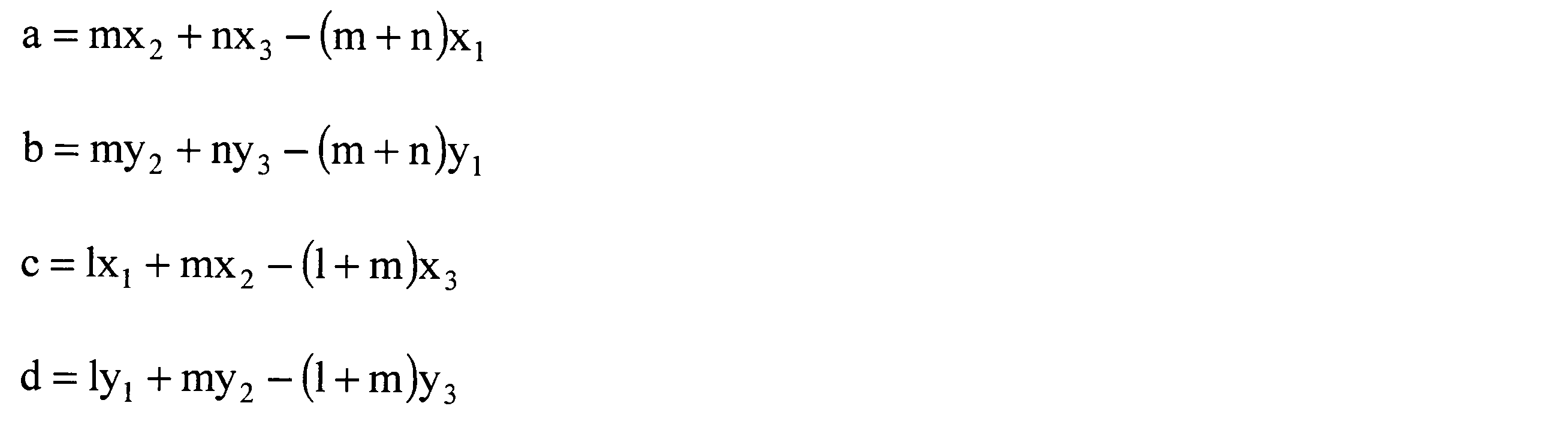
以上のように、第1実施形態に係る位置検出システム10は、対象領域内における移動通信装置20が存在する部分領域を特定し、部分領域を囲む3以上の固定通信装置30を選択する。そして、第1実施形態に係る位置検出システム10は、選択した3以上の固定通信装置30の位置、および、移動通信装置20と選択した3以上の固定通信装置30との間で無線通信された3以上の基準信号の受信点における電波強度に基づき、移動通信装置20を算出する。これにより、第1実施形態に係る位置検出システム10は、移動通信装置20の位置を精度良く検出することができる。
(第2実施形態)
つぎに、第2実施形態に係る位置検出システム10について説明をする。第2実施形態に係る位置検出システム10は、第1実施形態に係る位置検出システム10と略同一の機能および構成を有する。第2実施形態に係る位置検出システム10については、第1実施形態との相違点について説明をする。
つぎに、第2実施形態に係る位置検出システム10について説明をする。第2実施形態に係る位置検出システム10は、第1実施形態に係る位置検出システム10と略同一の機能および構成を有する。第2実施形態に係る位置検出システム10については、第1実施形態との相違点について説明をする。
図19は、第2実施形態に係る算出装置40の機能構成を、移動通信装置20および複数の固定通信装置30とともに示す図である。
第2実施形態に係る算出装置40は、特定部92をさらに有する。特定部92は、収集部70により収集された、複数の固定通信装置30と移動通信装置20との間で無線通信された複数の基準信号の受信点における電波強度を取得する。そして、特定部92は、複数の固定通信装置30の中から、移動通信装置20との間で無線通信された基準信号の受信点における電波強度が予め定められた範囲外となっている固定通信装置30を除外した複数の有効な固定通信装置30を特定する。
第2実施形態に係る装置選択部74は、特定部92により特定された有効な固定通信装置30の中から、選択された基準パターンに対応する部分領域に基づき3以上の有効な固定通信装置30を選択する。例えば、装置選択部74は、選択された基準パターンに対応する部分領域を囲む位置に配置された3以上の有効な固定通信装置30を選択する。
第2実施形態に係る位置算出部76は、装置選択部74により選択された3以上の有効な固定通信装置30のそれぞれの位置を位置記憶部64から取得する。また、位置算出部76は、装置選択部74により選択された3以上の有効な固定通信装置30と移動通信装置20との間で無線通信された、3以上の基準信号の受信点における電波強度を、収集部70から取得する。そして、位置算出部76は、選択された3以上の有効な固定通信装置30の位置、および、選択された3以上の有効な固定通信装置30と移動通信装置20との間で無線通信された、3以上の基準信号の受信点における電波強度に基づき、移動通信装置20の位置を算出する。
図20は、移動通信装置20の位置に対する、移動通信装置20と固定通信装置30との間で無線通信された基準信号の受信点における電波強度との関係を表す図である。
位置検出システム10は、移動通信装置20の位置を検出することができる領域(対象領域)が予め定められている。従って、移動通信装置20と固定通信装置30との間で無線通信された基準信号の受信点における電波強度の範囲(下限値から上限値までの範囲)は、理論的に定められる。すなわち、基準信号の受信点における電波強度は、移動通信装置20と固定通信装置30とが対象領域内で最も離れた場合に、理論的に最も小さくなる。また、基準信号の受信点における電波強度は、移動通信装置20と固定通信装置30とが対象領域内で最も近づいた場合に、理論的に最も大きくなる。
そこで、位置検出システム10の管理者は、図20に示すように、基準信号の受信点における電波強度の理論値の範囲の下限値からマージン値を減じた値から、上限値にマージン値を加えた値までの範囲を、有効範囲として予め設定する。特定部92は、複数の固定通信装置30と移動通信装置20との間で無線通信された複数の基準信号の受信点における電波強度が、予め設定された有効範囲内であるか否かを判断する。そして、特定部92は、複数の固定通信装置30の中から、移動通信装置20との間で無線通信された基準信号の受信点における電波強度が有効範囲内となる固定通信装置30を、有効な固定通信装置30として特定する。これにより、特定部92は、移動通信装置20との間で無線通信された基準信号の受信点における電波強度が、マルチパス等の影響により異常な値となる固定通信装置30を除外して、移動通信装置20の位置を算出させることができる。
なお、管理者は、固定通信装置30毎に、異なる有効範囲を設定してもよい。この場合、特定部92は、固定通信装置30毎に、対応する有効範囲を取得し、取得した有効範囲と、移動通信装置20との間で無線通信された基準信号の受信点における電波強度とを比較する。これにより、特定部92は、異常な値となる固定通信装置30をより精度良く除外することができる。
図21は、第2実施形態に係る算出装置40の処理の流れを示すフローチャートである。第2実施形態に係る算出装置40は、複数の固定通信装置30と移動通信装置20との間で、基準信号が送受信される毎に、図21に示す処理を実行する。図7に示した第1実施形態との相違点は、S13とS14との間に、S41の処理が実行される点である。
S41において、特定部92は、複数の固定通信装置30の中から、基準信号の受信点における電波強度が予め定められた範囲外となっている固定通信装置30を除外した複数の有効な固定通信装置30を特定する。続いて、S14において、装置選択部74は、S41で特定された有効な固定通信装置30の中から、選択された基準パターンに対応する部分領域に基づき3以上の有効な固定通信装置30を選択する。このような処理を実行することにより、位置検出システム10は、移動通信装置20との間で無線通信された基準信号の受信点における電波強度が異常な値となる固定通信装置30を除外して、移動通信装置20の位置を算出することができる。
なお、特定部92は、S41の処理を、S13より前に実行してもよい。また、この場合、S13において、パターン選択部72は、基準信号の受信点における電波強度が異常な値となる固定通信装置30を除外して、複数の基準パターンと測定パターンとを比較してもよい。つまり、この場合、パターン選択部72は、複数の基準パターンの中から、複数の有効な固定通信装置30と移動通信装置20との間で無線通信された複数の基準信号の受信点における電波強度を表すパターンに最も近い1つの基準パターンを選択する。これにより、算出装置40は、基準パターンを選択する段階から、基準信号の受信点における電波強度が異常となる固定通信装置30の測定値を除外することができる。
以上のように、第2実施形態に係る位置検出システム10は、電波強度が異常な値となる固定通信装置30を除外して、移動通信装置20の位置を算出する。これにより、第2実施形態に係る位置検出システム10によれば、マルチパス等の影響により基準信号の電波強度が異常に強まったり弱まったりした固定通信装置30が存在する場合であっても、移動通信装置20の位置を精度良く検出することができる。
(第3実施形態)
つぎに、第3実施形態に係る位置検出システム10について説明をする。第3実施形態に係る位置検出システム10は、第1実施形態に係る位置検出システム10と略同一の機能および構成を有する。第3実施形態に係る位置検出システム10については、第1実施形態との相違点について説明をする。なお、第3実施形態における相違点を第2実施形態に適用することも可能である。
つぎに、第3実施形態に係る位置検出システム10について説明をする。第3実施形態に係る位置検出システム10は、第1実施形態に係る位置検出システム10と略同一の機能および構成を有する。第3実施形態に係る位置検出システム10については、第1実施形態との相違点について説明をする。なお、第3実施形態における相違点を第2実施形態に適用することも可能である。
図22は、送信点におけるショートバースト信号の波形を示す図である。第3実施形態において、移動通信装置20は、第1間隔毎にショートバースト信号を複数の固定通信装置30のそれぞれと無線通信する。
ショートバースト信号は、所定の送信パワーで出力される所定間隔の複数の基準信号を含む。より具体的には、ショートバースト信号は、所定の送信パワーで出力されるN個(Nは2以上の整数)の基準信号を含む。図22の例では、ショートバースト信号は、5個の基準信号を含む。N個の基準信号は、第1間隔より短い第2間隔毎に送信される。
本実施形態において、移動通信装置20は、第1間隔毎に、複数の固定通信装置30のそれぞれにショートバースト信号を送信する。そして、本実施形態において、複数の固定通信装置30のそれぞれは、移動通信装置20から送信されたショートバースト信号を受信する。さらに、複数の固定通信装置30のそれぞれは、受信したショートバースト信号に含まれるN個の基準信号のそれぞれの電波強度を取得する。
なお、複数の固定通信装置30のそれぞれは、第1間隔毎に、ショートバースト信号を移動通信装置20に対して送信してもよい。この場合、移動通信装置20は、複数の固定通信装置30のそれぞれから送信された複数のショートバースト信号を受信する。さらに、この場合、移動通信装置20は、受信した複数のショートバースト信号のそれぞれについて、そのショートバースト信号に含まれるN個の基準信号のそれぞれの電波強度を取得する。また、この場合、複数の固定通信装置30は、それぞれが送信したショートバースト信号が干渉しないように、互いに時間をずらして基準信号を送信する。
図23は、第3実施形態に係る算出装置40の第1の処理の流れを示すフローチャートである。第3実施形態に係る算出装置40は、複数の固定通信装置30と移動通信装置20との間で、ショートバースト信号が送受信される毎に、図23に示す第1の処理を実行する。
まず、S51において、算出装置40は、ショートバースト信号に含まれる1つの基準信号が受信されたか否かを判断する。基準信号が受信されていない場合には(S51のNo)、算出装置40は、処理をS51で待機する。基準信号が受信された場合には(S51のYes)、算出装置40は、処理をS52に進める。
S52において、算出装置40は、受信された基準信号に基づき、移動通信装置20の位置を算出する。この場合において、算出装置40は、図7のS11~S18の処理を実行する。
続いて、S53において、算出装置40は、算出した位置を記憶する。続いて、S54において、算出装置40は、基準信号を所定回受信したか否かを判断する。例えば、算出装置40は、ショートバースト信号に含まれるN個の基準信号の全てについて、位置を算出したか否かを判断する。基準信号を所定回受信していない場合には(S54のNo)、算出装置40は、処理をS51に戻し、S51から処理を繰り返す。基準信号を所定回受信した場合には(S54のYes)、算出装置40は、処理をS55に進める。
S55において、算出装置40は、所定回数分算出した位置の平均値を算出する。そして、算出装置40は、平均した位置を、移動通信装置20の位置として出力する。なお、算出装置40は、位置の平均値に代えて、位置の中央値を算出してもよい。
図24は、第3実施形態に係る算出装置40の第2の処理の流れを示すフローチャートである。第3実施形態に係る算出装置40は、複数の固定通信装置30と移動通信装置20との間で、ショートバースト信号が送受信される毎に、図24に示す第2の処理を実行してもよい。
まず、S61において、算出装置40は、ショートバースト信号に含まれる1つの基準信号が受信されたか否かを判断する。基準信号が受信されていない場合には(S61のNo)、算出装置40は、処理をS61で待機する。基準信号が受信された場合には(S61のYes)、算出装置40は、処理をS62に進める。
続いて、S62において、算出装置40は、受信した基準信号の電波強度を記憶する。この場合において、算出装置40は、固定通信装置30毎に電波強度を記憶する。
続いて、S63において、算出装置40は、基準信号を所定回受信したか否かを判断する。例えば、算出装置40は、ショートバースト信号に含まれるN個の基準信号の全てについて、基準信号を受信したか否かを判断する。基準信号を所定回受信していない場合には(S63のNo)、算出装置40は、処理をS61に戻し、S61から処理を繰り返す。基準信号を所定回受信した場合には(S63のYes)、算出装置40は、処理をS64に進める。
S64において、算出装置40は、所定回分算出した電波強度の平均値を算出する。この場合において、算出装置40は、固定通信装置30毎に電波強度の平均値を算出する。なお、算出装置40は、電波強度の平均値に代えて、電波強度の中央値を算出してもよい。
続いて、S64において、算出装置40は、固定通信装置30毎の電波強度の平均値に基づき、移動通信装置20の位置を算出する。この場合において、算出装置40は、図7のS11~S18の処理を実行する。そして、算出装置40は、算出した位置を、移動通信装置20の位置として出力する。
以上のように、第3実施形態に係る位置検出システム10は、ショートバースト信号を用いて、移動通信装置20の位置を算出する。これにより、第3実施形態に係る位置検出システム10によれば、送信電力または受信感度が瞬時的に乱れた場合であっても、検出する位置のばらつきを小さくして、移動通信装置20の位置を精度良く検出することができる。
(情報処理装置200のハードウェア構成)
図25は、情報処理装置200のハードウェア構成を示す図である。移動通信装置20、固定通信装置30および算出装置40は、例えば、図25に示すような、通信機能を有する情報処理装置200により実現することができる。情報処理装置200は、一例として、一般のコンピュータと同様のハードウェア構成により実現される。情報処理装置200は、CPU(Central Processing Unit)202と、ROM(Read Only Memory)204と、RAM(Random Access Memory)206と、記憶装置208と、無線通信装置210と、ネットワークインターフェース装置212とを備える。各部は、バスにより接続される。
図25は、情報処理装置200のハードウェア構成を示す図である。移動通信装置20、固定通信装置30および算出装置40は、例えば、図25に示すような、通信機能を有する情報処理装置200により実現することができる。情報処理装置200は、一例として、一般のコンピュータと同様のハードウェア構成により実現される。情報処理装置200は、CPU(Central Processing Unit)202と、ROM(Read Only Memory)204と、RAM(Random Access Memory)206と、記憶装置208と、無線通信装置210と、ネットワークインターフェース装置212とを備える。各部は、バスにより接続される。
CPU202は、RAM206の所定領域を作業領域としてROM204または記憶装置208に予め記憶された各種プログラムとの協働により各種処理を実行し、情報処理装置200を構成する各部の動作を統括的に制御する。また、CPU202は、ROM204または記憶装置208に予め記憶されたプログラムとの協働により無線通信装置210およびネットワークインターフェース装置212等を動作させる。
ROM204は、情報処理装置200の制御に用いられるプログラムおよび各種設定情報等を書き換え不可能に記憶する。RAM206は、SDRAM(Synchronous Dynamic Random Access Memory)等の揮発性の記憶媒体である。RAM206は、CPU202の作業領域として機能する。
記憶装置208は、フラッシュメモリ等の半導体による記憶媒体、磁気的または光学的に記録可能な記憶媒体等の書き換え可能な記録装置である。記憶装置208は、情報処理装置200の制御に用いられるプログラムを記憶する。
無線通信装置210は、Wi-Fi(登録商標)またはBluetooth(登録商標)等により他の装置と無線通信を行う。無線通信装置210は、移動通信装置20および固定通信装置30に適用された場合、基準信号の送受信を行う。なお、算出装置40は、無線通信装置210を備えない構成であってもよい。
ネットワークインターフェース装置212は、他の装置とインターネット等を介して情報を送受信する。例えば、ネットワークインターフェース装置212は、算出装置40に適用された場合、基準信号の受信点における電波強度を、移動通信装置20または固定通信装置30から受信する。なお、移動通信装置20は、固定通信装置30を介してインターネット等のネットワークに接続する場合には、ネットワークインターフェース装置212を備えない構成であってもよい。
情報処理装置200が算出装置40として動作する場合、情報処理装置200で実行されるプログラムは、例えば、インターネット等のネットワークに接続されたコンピュータ上に格納され、ネットワーク経由でダウンロードさせることにより提供される。また、情報処理装置200が算出装置40として動作する場合、情報処理装置200で実行されるプログラムは、持ち運び可能な記憶媒体等に予め組み込んで提供されてもよい。
情報処理装置200が算出装置40として機能する場合、情報処理装置200で実行されるプログラムは、収集モジュールと、パターン選択モジュールと、装置選択モジュールと、位置算出モジュールとを含むモジュール構成となっている。CPU202(プロセッサ)は、記憶媒体等からこのようなプログラムを読み出して、上記各モジュールをRAM206(主記憶装置)にロードする。そして、CPU202(プロセッサ)は、このようなプログラムを実行することにより、収集部70、パターン選択部72、装置選択部74および位置算出部76として機能する。また、記憶装置208は、パターン記憶部62および位置記憶部64として機能する。なお、収集部70、パターン選択部72、装置選択部74および位置算出部76の一部または全部がハードウェアにより構成されていてもよい。
以上、本発明の実施形態を説明したが、これらの実施形態は、例として提示したものであり、発明の範囲を限定することは意図していない。実施形態は、種々の変更を行うことができる。
10 位置検出システム
20 移動通信装置
30 固定通信装置
30-1 第1の固定通信装置
30-2 第2の固定通信装置
30-3 第3の固定通信装置
40 算出装置
50 基準通信機
62 パターン記憶部
64 位置記憶部
70 収集部
72 パターン選択部
74 装置選択部
76 位置算出部
92 特定部
121 第1直線
122 第2直線
20 移動通信装置
30 固定通信装置
30-1 第1の固定通信装置
30-2 第2の固定通信装置
30-3 第3の固定通信装置
40 算出装置
50 基準通信機
62 パターン記憶部
64 位置記憶部
70 収集部
72 パターン選択部
74 装置選択部
76 位置算出部
92 特定部
121 第1直線
122 第2直線
Claims (9)
- 予め定められた位置に配置された複数の固定通信装置と、
所定の送信パワーで出力される基準信号を前記複数の固定通信装置のそれぞれと無線通信する移動通信装置と、
前記複数の固定通信装置の中から、前記移動通信装置との間で無線通信された前記基準信号の受信点における電波強度が予め定められた範囲外となっている固定通信装置を除外した複数の有効な固定通信装置を特定する特定部と、
前記複数の有効な固定通信装置の位置、および、前記複数の有効な固定通信装置と前記移動通信装置との間で無線通信された複数の前記基準信号の受信点における電波強度に基づき、前記移動通信装置の位置を算出する位置算出部と、
を備える位置検出システム。 - 前記移動通信装置の位置を検出する対象領域を分割した複数の部分領域に一対一に対応した複数の基準パターンの中から、前記複数の固定通信装置と前記移動通信装置との間で無線通信された複数の前記基準信号の受信点における電波強度を表す測定パターンに最も近い1つの基準パターンを選択するパターン選択部と、
前記複数の有効な固定通信装置の中から、選択された基準パターンに対応する部分領域に基づき3以上の有効な固定通信装置を選択する装置選択部と、
をさらに備え、
前記位置算出部は、選択された前記3以上の有効な固定通信装置の位置、および、選択された前記3以上の有効な固定通信装置と前記移動通信装置との間で無線通信された3以上の前記基準信号の受信点における電波強度に基づき、前記移動通信装置の位置を算出する
請求項1に記載の位置検出システム。 - 位置を検出する対象領域を分割した複数の部分領域に一対一に対応した複数の基準パターンの中から、前記複数の有効な固定通信装置と前記移動通信装置との間で無線通信された複数の前記基準信号の受信点における電波強度を表すパターンに最も近い1つの基準パターンを選択するパターン選択部と、
前記複数の有効な固定通信装置の中から、選択された基準パターンに対応する部分領域に基づき3以上の有効な固定通信装置を選択する装置選択部と、
をさらに備え、
前記位置算出部は、選択された前記3以上の固定通信装置の位置、および、選択された前記3以上の固定通信装置と前記移動通信装置との間で無線通信された3以上の前記基準信号の受信点における電波強度に基づき、前記移動通信装置の位置を算出する
請求項1に記載の位置検出システム。 - 前記複数の基準パターンのそれぞれは、対応する部分領域に配置された基準通信機と、前記複数の固定通信装置との間で無線通信された、複数の前記基準信号の受信点における電波強度を表す
請求項2または3に記載の位置検出システム。 - 前記移動通信装置は、前記基準信号を送信し、
前記複数の固定通信装置のそれぞれは、前記移動通信装置から送信された前記基準信号を受信する
請求項1から4の何れか1項に記載の位置検出システム。 - 前記複数の固定通信装置のそれぞれは、前記基準信号を送信し、
前記移動通信装置は、前記複数の固定通信装置のそれぞれから送信された前記基準信号を受信する
請求項1から4の何れか1項に記載の位置検出システム。 - 予め定められた位置に配置された複数の固定通信装置と、所定の送信パワーで出力される基準信号を前記複数の固定通信装置のそれぞれと無線通信する移動通信装置と、を備える位置検出システムに用いられる、前記移動通信装置の位置を算出する算出装置であって、
前記複数の固定通信装置の中から、前記移動通信装置との間で無線通信された前記基準信号の受信点における電波強度が予め定められた範囲外となっている固定通信装置を除外した複数の有効な固定通信装置を特定する特定部と、
前記複数の有効な固定通信装置の位置、および、前記複数の有効な固定通信装置と前記移動通信装置との間で無線通信された複数の前記基準信号の受信点における電波強度に基づき、前記移動通信装置の位置を算出する位置算出部と、
を有する算出装置。 - 予め定められた位置に配置された複数の固定通信装置と、所定の送信パワーで出力される基準信号を前記複数の固定通信装置のそれぞれと無線通信する移動通信装置と、を備える位置検出システムに用いられる、情報処理装置を前記移動通信装置の位置を算出する算出装置として機能させるためのプログラムであって、
前記情報処理装置に、
前記複数の固定通信装置の中から、前記移動通信装置との間で無線通信された前記基準信号の受信点における電波強度が予め定められた範囲外となっている固定通信装置を除外した複数の有効な固定通信装置を特定する特定ステップと、
前記複数の有効な固定通信装置の位置、および、前記複数の有効な固定通信装置と前記移動通信装置との間で無線通信された複数の前記基準信号の受信点における電波強度に基づき、前記移動通信装置の位置を算出する位置算出ステップと、
を実行させるプログラム。 - 予め定められた位置に配置された複数の固定通信装置と、所定の送信パワーで出力される基準信号を前記複数の固定通信装置のそれぞれと無線通信する移動通信装置と、を備える位置検出システムに用いられる、前記移動通信装置の位置を算出する算出装置において実行される位置検出方法であって、
前記算出装置が、
前記複数の固定通信装置の中から、前記移動通信装置との間で無線通信された前記基準信号の受信点における電波強度が予め定められた範囲外となっている固定通信装置を除外した複数の有効な固定通信装置を特定する特定ステップと、
前記複数の有効な固定通信装置の位置、および、前記複数の有効な固定通信装置と前記移動通信装置との間で無線通信された複数の前記基準信号の受信点における電波強度に基づき、前記移動通信装置の位置を算出する位置算出ステップと、
を実行する位置検出方法。
Priority Applications (1)
| Application Number | Priority Date | Filing Date | Title |
|---|---|---|---|
| JP2020532137A JP7167157B2 (ja) | 2018-07-26 | 2019-01-31 | 位置検出システム、算出装置、プログラムおよび位置検出方法 |
Applications Claiming Priority (2)
| Application Number | Priority Date | Filing Date | Title |
|---|---|---|---|
| JP2018140697 | 2018-07-26 | ||
| JP2018-140697 | 2018-07-26 |
Publications (1)
| Publication Number | Publication Date |
|---|---|
| WO2020021738A1 true WO2020021738A1 (ja) | 2020-01-30 |
Family
ID=69180403
Family Applications (1)
| Application Number | Title | Priority Date | Filing Date |
|---|---|---|---|
| PCT/JP2019/003506 Ceased WO2020021738A1 (ja) | 2018-07-26 | 2019-01-31 | 位置検出システム、算出装置、プログラムおよび位置検出方法 |
Country Status (2)
| Country | Link |
|---|---|
| JP (1) | JP7167157B2 (ja) |
| WO (1) | WO2020021738A1 (ja) |
Cited By (3)
| Publication number | Priority date | Publication date | Assignee | Title |
|---|---|---|---|---|
| JP2020112521A (ja) * | 2019-01-16 | 2020-07-27 | 太陽誘電株式会社 | 位置検出システム、算出装置、プログラムおよび位置検出方法 |
| JPWO2022259665A1 (ja) * | 2021-06-10 | 2022-12-15 | ||
| JP2023042094A (ja) * | 2021-09-14 | 2023-03-27 | 戸田建設株式会社 | 位置管理システム |
Citations (6)
| Publication number | Priority date | Publication date | Assignee | Title |
|---|---|---|---|---|
| JPH10282204A (ja) * | 1997-04-10 | 1998-10-23 | Hitachi Zosen Corp | 移動体の位置検出設備 |
| JP2000348297A (ja) * | 1999-06-08 | 2000-12-15 | Seiko Epson Corp | 移動端末装置、サービスセンタ、および位置情報検出表示システム |
| JP2006300918A (ja) * | 2005-03-25 | 2006-11-02 | Oki Electric Ind Co Ltd | 位置測定システムおよび位置測定方法 |
| JP2007121014A (ja) * | 2005-10-26 | 2007-05-17 | Nec Tokin Corp | 物品位置検出システム |
| JP2011217267A (ja) * | 2010-04-01 | 2011-10-27 | Nippon Telegr & Teleph Corp <Ntt> | エリア推定装置、エリア推定方法、及びプログラム |
| JP2017003455A (ja) * | 2015-06-11 | 2017-01-05 | アルパイン株式会社 | 電子装置、位置特定プログラムおよび位置特定方法 |
-
2019
- 2019-01-31 WO PCT/JP2019/003506 patent/WO2020021738A1/ja not_active Ceased
- 2019-01-31 JP JP2020532137A patent/JP7167157B2/ja active Active
Patent Citations (6)
| Publication number | Priority date | Publication date | Assignee | Title |
|---|---|---|---|---|
| JPH10282204A (ja) * | 1997-04-10 | 1998-10-23 | Hitachi Zosen Corp | 移動体の位置検出設備 |
| JP2000348297A (ja) * | 1999-06-08 | 2000-12-15 | Seiko Epson Corp | 移動端末装置、サービスセンタ、および位置情報検出表示システム |
| JP2006300918A (ja) * | 2005-03-25 | 2006-11-02 | Oki Electric Ind Co Ltd | 位置測定システムおよび位置測定方法 |
| JP2007121014A (ja) * | 2005-10-26 | 2007-05-17 | Nec Tokin Corp | 物品位置検出システム |
| JP2011217267A (ja) * | 2010-04-01 | 2011-10-27 | Nippon Telegr & Teleph Corp <Ntt> | エリア推定装置、エリア推定方法、及びプログラム |
| JP2017003455A (ja) * | 2015-06-11 | 2017-01-05 | アルパイン株式会社 | 電子装置、位置特定プログラムおよび位置特定方法 |
Cited By (5)
| Publication number | Priority date | Publication date | Assignee | Title |
|---|---|---|---|---|
| JP2020112521A (ja) * | 2019-01-16 | 2020-07-27 | 太陽誘電株式会社 | 位置検出システム、算出装置、プログラムおよび位置検出方法 |
| JPWO2022259665A1 (ja) * | 2021-06-10 | 2022-12-15 | ||
| JP7724482B2 (ja) | 2021-06-10 | 2025-08-18 | パナソニックIpマネジメント株式会社 | 測位方法、プログラム及び測位システム |
| JP2023042094A (ja) * | 2021-09-14 | 2023-03-27 | 戸田建設株式会社 | 位置管理システム |
| JP7752497B2 (ja) | 2021-09-14 | 2025-10-10 | 戸田建設株式会社 | 位置管理システム |
Also Published As
| Publication number | Publication date |
|---|---|
| JP7167157B2 (ja) | 2022-11-08 |
| JPWO2020021738A1 (ja) | 2021-08-05 |
Similar Documents
| Publication | Publication Date | Title |
|---|---|---|
| US12047863B2 (en) | Methods and apparatus relating to the use of real and/or virtual beacons | |
| US8983490B2 (en) | Locating a mobile device | |
| CN103354909B (zh) | 位置确定装置、方法、系统、空气调节系统以及照明系统 | |
| EP3594711B1 (en) | Determining a plurality of potential installation positions | |
| US11032726B2 (en) | Optimization system for distributed antenna system | |
| US20160345129A1 (en) | Positioning system for indoor and surrounding areas, positioning method and route-planning method thereof and mobile apparatus | |
| KR20160133716A (ko) | 측위 환경 분석 장치, 이를 이용한 단말기의 위치 결정 성능 예측 방법 및 시스템 | |
| JP6611117B2 (ja) | 電子装置、位置特定プログラムおよび位置特定方法 | |
| JP2010085290A (ja) | 位置検出装置、位置検出システム、位置検出方法およびプログラム | |
| JP7167157B2 (ja) | 位置検出システム、算出装置、プログラムおよび位置検出方法 | |
| EP3897001A1 (en) | Position sensing method and device and positioning method and device | |
| JP6803412B2 (ja) | 位置検出システム、算出装置、プログラムおよび位置検出方法 | |
| KR20150141299A (ko) | 실시간 재난대응 위치파악 및 피난경로 안내 솔루션 | |
| US11156694B2 (en) | Supporting a selection of a floor | |
| JP7245837B2 (ja) | 位置検出システム、算出装置、プログラムおよび位置検出方法 | |
| TW201809717A (zh) | 室內定位系統及其方法 | |
| JP7245836B2 (ja) | 位置検出システム、算出装置、プログラムおよび位置検出方法 | |
| KR102442282B1 (ko) | 실내 위치 측위 장치 및 방법 | |
| KR102402743B1 (ko) | 위치 측정 방법 및 전자장치 | |
| KR101397648B1 (ko) | 선박 내의 지그비 노드 배치 방법 및 그 장치 | |
| JP2021169963A (ja) | 位置特定方法、及び位置特定システム | |
| KR20170050132A (ko) | 위치 측정 시스템 및 방법 | |
| KR20160125274A (ko) | iBeacon 기반의 단말 간 3차원 상대위치 인식 방법 및 시스템 |
Legal Events
| Date | Code | Title | Description |
|---|---|---|---|
| 121 | Ep: the epo has been informed by wipo that ep was designated in this application |
Ref document number: 19841826 Country of ref document: EP Kind code of ref document: A1 |
|
| ENP | Entry into the national phase |
Ref document number: 2020532137 Country of ref document: JP Kind code of ref document: A |
|
| NENP | Non-entry into the national phase |
Ref country code: DE |
|
| 122 | Ep: pct application non-entry in european phase |
Ref document number: 19841826 Country of ref document: EP Kind code of ref document: A1 |