WO2020021715A1 - Procédé de contre-mesure de fraude, dispositif de contre-mesure de fraude et système de communication - Google Patents
Procédé de contre-mesure de fraude, dispositif de contre-mesure de fraude et système de communication Download PDFInfo
- Publication number
- WO2020021715A1 WO2020021715A1 PCT/JP2018/028297 JP2018028297W WO2020021715A1 WO 2020021715 A1 WO2020021715 A1 WO 2020021715A1 JP 2018028297 W JP2018028297 W JP 2018028297W WO 2020021715 A1 WO2020021715 A1 WO 2020021715A1
- Authority
- WO
- WIPO (PCT)
- Prior art keywords
- frame
- fraud
- slot
- switching
- predetermined
- Prior art date
Links
Images


Classifications
-
- H—ELECTRICITY
- H04—ELECTRIC COMMUNICATION TECHNIQUE
- H04L—TRANSMISSION OF DIGITAL INFORMATION, e.g. TELEGRAPHIC COMMUNICATION
- H04L63/00—Network architectures or network communication protocols for network security
- H04L63/14—Network architectures or network communication protocols for network security for detecting or protecting against malicious traffic
- H04L63/1408—Network architectures or network communication protocols for network security for detecting or protecting against malicious traffic by monitoring network traffic
-
- B—PERFORMING OPERATIONS; TRANSPORTING
- B60—VEHICLES IN GENERAL
- B60R—VEHICLES, VEHICLE FITTINGS, OR VEHICLE PARTS, NOT OTHERWISE PROVIDED FOR
- B60R16/00—Electric or fluid circuits specially adapted for vehicles and not otherwise provided for; Arrangement of elements of electric or fluid circuits specially adapted for vehicles and not otherwise provided for
- B60R16/02—Electric or fluid circuits specially adapted for vehicles and not otherwise provided for; Arrangement of elements of electric or fluid circuits specially adapted for vehicles and not otherwise provided for electric constitutive elements
- B60R16/023—Electric or fluid circuits specially adapted for vehicles and not otherwise provided for; Arrangement of elements of electric or fluid circuits specially adapted for vehicles and not otherwise provided for electric constitutive elements for transmission of signals between vehicle parts or subsystems
- B60R16/0231—Circuits relating to the driving or the functioning of the vehicle
- B60R16/0232—Circuits relating to the driving or the functioning of the vehicle for measuring vehicle parameters and indicating critical, abnormal or dangerous conditions
-
- H—ELECTRICITY
- H04—ELECTRIC COMMUNICATION TECHNIQUE
- H04L—TRANSMISSION OF DIGITAL INFORMATION, e.g. TELEGRAPHIC COMMUNICATION
- H04L12/00—Data switching networks
- H04L12/28—Data switching networks characterised by path configuration, e.g. LAN [Local Area Networks] or WAN [Wide Area Networks]
- H04L12/40—Bus networks
- H04L12/4013—Management of data rate on the bus
-
- H—ELECTRICITY
- H04—ELECTRIC COMMUNICATION TECHNIQUE
- H04L—TRANSMISSION OF DIGITAL INFORMATION, e.g. TELEGRAPHIC COMMUNICATION
- H04L12/00—Data switching networks
- H04L12/28—Data switching networks characterised by path configuration, e.g. LAN [Local Area Networks] or WAN [Wide Area Networks]
- H04L12/40—Bus networks
- H04L12/40052—High-speed IEEE 1394 serial bus
- H04L12/40084—Bus arbitration
-
- H—ELECTRICITY
- H04—ELECTRIC COMMUNICATION TECHNIQUE
- H04L—TRANSMISSION OF DIGITAL INFORMATION, e.g. TELEGRAPHIC COMMUNICATION
- H04L12/00—Data switching networks
- H04L12/28—Data switching networks characterised by path configuration, e.g. LAN [Local Area Networks] or WAN [Wide Area Networks]
- H04L12/44—Star or tree networks
-
- H—ELECTRICITY
- H04—ELECTRIC COMMUNICATION TECHNIQUE
- H04L—TRANSMISSION OF DIGITAL INFORMATION, e.g. TELEGRAPHIC COMMUNICATION
- H04L12/00—Data switching networks
- H04L12/64—Hybrid switching systems
- H04L12/6418—Hybrid transport
-
- H—ELECTRICITY
- H04—ELECTRIC COMMUNICATION TECHNIQUE
- H04L—TRANSMISSION OF DIGITAL INFORMATION, e.g. TELEGRAPHIC COMMUNICATION
- H04L63/00—Network architectures or network communication protocols for network security
- H04L63/14—Network architectures or network communication protocols for network security for detecting or protecting against malicious traffic
- H04L63/1408—Network architectures or network communication protocols for network security for detecting or protecting against malicious traffic by monitoring network traffic
- H04L63/1425—Traffic logging, e.g. anomaly detection
-
- H—ELECTRICITY
- H04—ELECTRIC COMMUNICATION TECHNIQUE
- H04L—TRANSMISSION OF DIGITAL INFORMATION, e.g. TELEGRAPHIC COMMUNICATION
- H04L63/00—Network architectures or network communication protocols for network security
- H04L63/14—Network architectures or network communication protocols for network security for detecting or protecting against malicious traffic
- H04L63/1433—Vulnerability analysis
-
- H—ELECTRICITY
- H04—ELECTRIC COMMUNICATION TECHNIQUE
- H04L—TRANSMISSION OF DIGITAL INFORMATION, e.g. TELEGRAPHIC COMMUNICATION
- H04L12/00—Data switching networks
- H04L12/28—Data switching networks characterised by path configuration, e.g. LAN [Local Area Networks] or WAN [Wide Area Networks]
- H04L12/40—Bus networks
- H04L2012/40208—Bus networks characterized by the use of a particular bus standard
- H04L2012/40215—Controller Area Network CAN
-
- H—ELECTRICITY
- H04—ELECTRIC COMMUNICATION TECHNIQUE
- H04L—TRANSMISSION OF DIGITAL INFORMATION, e.g. TELEGRAPHIC COMMUNICATION
- H04L12/00—Data switching networks
- H04L12/28—Data switching networks characterised by path configuration, e.g. LAN [Local Area Networks] or WAN [Wide Area Networks]
- H04L12/40—Bus networks
- H04L2012/40208—Bus networks characterized by the use of a particular bus standard
- H04L2012/40241—Flexray
-
- H—ELECTRICITY
- H04—ELECTRIC COMMUNICATION TECHNIQUE
- H04L—TRANSMISSION OF DIGITAL INFORMATION, e.g. TELEGRAPHIC COMMUNICATION
- H04L12/00—Data switching networks
- H04L12/28—Data switching networks characterised by path configuration, e.g. LAN [Local Area Networks] or WAN [Wide Area Networks]
- H04L12/40—Bus networks
- H04L2012/40267—Bus for use in transportation systems
- H04L2012/40273—Bus for use in transportation systems the transportation system being a vehicle
-
- H—ELECTRICITY
- H04—ELECTRIC COMMUNICATION TECHNIQUE
- H04L—TRANSMISSION OF DIGITAL INFORMATION, e.g. TELEGRAPHIC COMMUNICATION
- H04L12/00—Data switching networks
- H04L12/64—Hybrid switching systems
- H04L12/6418—Hybrid transport
- H04L2012/6432—Topology
- H04L2012/644—Star
Definitions
- the present invention relates to a method, a system, and an apparatus for transmitting a frame even when a communication error occurs on a vehicle-mounted network.
- ECUs electronice control units
- a network connecting these ECUs is called an in-vehicle network.
- FlexRay which is designed as a protocol that is faster and more reliable than the currently mainstream Controller @ Area @ Network (hereinafter, CAN).
- FlexRay represents a value of “0” and a value of “1” by a voltage difference between two stranded wires.
- the ECU connected to the bus is called a node.
- Each node connected to the bus sends and receives messages called frames.
- FlexRay is a Time ⁇ Division ⁇ Multiple ⁇ Access (TDMA) system, and each node transmits a frame at a predetermined timing.
- TDMA Time ⁇ Division ⁇ Multiple ⁇ Access
- a cycle is composed of four segments: a "static segment”, a “dynamic segment”, a “symbol window”, and a "network idle time”.
- the dynamic segment and the symbol window are optional.
- Each node sends frames in static and dynamic segments.
- the static segment and the dynamic segment are further composed of time during which one frame called a slot can be transmitted.
- the transmission node transmits a frame based on a slot number that is a transmission timing predetermined for each frame.
- Each receiving node receives only a frame with a predetermined slot number.
- a method called “cycle multiplexing” that realizes communication of different frames depending on the cycle even in the case of frames having the same slot number may be used.
- Patent Literature 1 proposes an in-vehicle network monitoring device that detects whether a frame is transmitted to a CAN at a predetermined communication interval, and determines that a frame deviating from the specified communication interval is invalid. Discloses a method for preventing control by an illegal frame.
- the present invention solves the above problem by detecting a frame to be transmitted illegally and then switching a communication slot for transmitting the frame, thereby reducing the range of influence by the frame transmitted illegally. It is intended to provide a simple in-vehicle network system.
- a fraud countermeasure method is a fraud countermeasure method in an in-vehicle network that is a time-triggered communication method based on a time slot, wherein the in-vehicle network includes one or more Electronic control devices are connected, each of the electronic control devices transmits and receives a frame within a predetermined time slot, the electronic control device performs a frame transmission and reception step of transmitting and receiving the frame, A fraud detecting step for detecting, and a switching determining step of performing a transmission frame switching process in accordance with a predetermined setting when a predetermined condition is satisfied based on a determination result of the fraud detecting step.
- the present invention even if an illegal frame is transmitted to the in-vehicle network, it is possible to maintain a safe state as a whole in-vehicle network system by detecting the invalid frame and taking action.
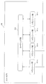
- FIG. 1 is an overall configuration diagram of a vehicle-mounted network system 10 according to the first embodiment.
- FIG. 2 is a diagram showing a cycle of FlexRay communication according to the first embodiment.
- FIG. 3 is a diagram showing a frame format of FlexRay communication according to the first embodiment.
- FIG. 4 is a diagram illustrating an example of a configuration of the ECU 200a according to the first embodiment.
- FIG. 5 is a diagram illustrating an example of communication setting parameters for FlexRay communication according to the first embodiment.
- FIG. 6 is a diagram illustrating an example of a configuration of the star coupler 300 according to the first embodiment.
- FIG. 7 is a diagram illustrating an example of a frame list transmitted by FlexRay communication according to the first embodiment.
- FIG. 1 is an overall configuration diagram of a vehicle-mounted network system 10 according to the first embodiment.
- FIG. 2 is a diagram showing a cycle of FlexRay communication according to the first embodiment.
- FIG. 3 is a diagram showing a frame format of FlexRay communication according to the first
- FIG. 8 is a diagram illustrating an example of a frame transmission schedule of FlexRay communication according to the first embodiment.
- FIG. 9 is a diagram illustrating an example of the switching table according to the first embodiment.
- FIG. 10 is a diagram showing an example of a switching communication sequence according to the first embodiment.
- FIG. 11 is an overall configuration diagram of the vehicle-mounted network system 20 according to the second embodiment.
- FIG. 12 is a diagram illustrating an example of a configuration of the ECU 1200a according to the second embodiment.
- FIG. 13 is a diagram illustrating an example of a switching table according to the second embodiment.
- FIG. 14 is a diagram showing an example of a switching communication sequence according to the second embodiment.
- a fraud countermeasure method is a fraud countermeasure method in a vehicle-mounted network that is a time-triggered communication system based on a time slot, wherein one or more electronic control devices are connected to the vehicle-mounted network, Each of the electronic control units transmits and receives a frame within a predetermined time slot, and the electronic control unit transmits and receives the frame, a frame transmitting and receiving step, a fraud detection step of detecting an invalid frame, A switching determination step of performing a transmission frame switching process according to a predetermined setting when a predetermined condition is satisfied based on a determination result of the fraud detection step.
- the fraud countermeasure method is characterized in that, as the fraud detecting step, the fraud of the frame is determined by a predetermined attack determination algorithm.
- the fraud countermeasure method according to an embodiment of the present invention is characterized in that, as the predetermined setting, one of a static slot and a dynamic slot is designated as a switching source slot.
- the fraud countermeasure method according to an embodiment of the present invention is characterized in that, as the predetermined setting, one of a static slot and a dynamic slot is designated as a switching destination slot.
- the fraud countermeasure method is characterized in that, as the predetermined setting, an empty slot to which a frame has not been allocated is designated as a switching destination slot.
- the fraud countermeasure method is characterized in that, as the predetermined setting, a slot to which a frame has already been assigned is designated as a switching destination slot.
- the fraud countermeasure method is characterized in that, as the predetermined setting, a payload of an already allocated frame is combined with a payload of a switched frame.
- the fraud countermeasure method according to an embodiment of the present invention is characterized in that a new slot is added as the switching destination slot as the predetermined setting.
- the fraud countermeasure method is characterized in that, as the predetermined setting, a payload of an already allocated frame is exchanged with a payload of a switched frame.
- the fraudulent response method is characterized in that a switching process is performed by detecting occurrence of an error according to the communication method as the predetermined condition.
- the fraudulent response method is characterized in that, as the predetermined condition, a switching process is performed by detecting a frame other than the frame in which the fraud has occurred.
- the fraudulent countermeasure method is characterized in that a switching process is performed as the predetermined condition according to a preset state of a vehicle equipped with the in-vehicle network.
- the fraudulent response method is characterized in that the state of the vehicle is any one of a state of being parked, a state of being stopped, and a state of running.
- a communication system in an in-vehicle network that is a time-triggered communication method based on a time slot, wherein one or more electronic control devices are connected to the in-vehicle network, and each of the electronic control devices is a predetermined predetermined number.
- the electronic control unit transmits and receives a frame within the time slot, and the electronic control unit performs a frame transmission and reception step of transmitting and receiving the frame, a fraud detection step of detecting an illegal frame, and a predetermined result based on a determination result of the fraud detection step.
- a switching determination step of performing a transmission frame switching process according to a predetermined setting when the condition is satisfied.
- an electronic control device connected to the in-vehicle network is one or more, wherein each of the electronic control devices is a predetermined predetermined number.
- a frame transmitting / receiving unit for transmitting / receiving a frame within the time slot of the frame, a frame transmitting / receiving unit for transmitting / receiving the frame, a fraud detecting unit for detecting a fraudulent frame, and based on a determination result of the fraud detecting step, when a predetermined condition is satisfied ,
- a switching determination unit that performs a transmission frame switching process according to a predetermined setting.
- FIG. 1 is a diagram showing the overall configuration of an in-vehicle network system 10 according to the present invention.
- the in-vehicle network system 10 includes FlexRay buses 100a, 100b, 100c, and 100d, ECUs 200a, 200b, 200c, and 200d connected to each bus, and a front camera 210, a gear 220, and a brake 230 that are controlled by each ECU. It comprises a rear camera 240 and a star coupler 300 for connecting each FlexRay bus.
- the ECUs 200a to 200d realize control of the vehicle by transmitting and receiving frames via the FlexRay bus.
- the star coupler shapes the signals so that the same signal flows in every bus, and the ECUs are synchronized through the FlexRay bus.
- FIG. 2 is a diagram showing a cycle of FlexRay communication according to the present invention. FlexRay communication is performed in units called a cycle, and each node synchronously holds the number of cycle repetitions (cycle counter). The cycle counter takes a value of 0 to 63. The next cycle in which the cycle counter is 63 resets the cycle counter to zero.
- Each cycle is composed of four segments: a static segment (Static segment), a dynamic segment (Dynamic segment), a symbol window (Symbol window), and a network idle time (NIT). Since the time of each segment is common to the entire FlexRay network (cluster) according to parameters designed in advance, the time of one cycle is also common to the cluster.
- Static segment static segment
- Dynamic segment dynamic segment
- Symbol window symbol window
- NIT network idle time
- the static segment is composed of multiple slots.
- the number of slots and the time of each slot are common in the cluster.
- one frame is transmitted in one slot, and the slot number becomes a frame identifier (Frame (ID).
- Each ECU is designed to transmit a frame at a predetermined timing (slot number).
- a frame transmitted in a static segment is called a static frame.
- the static frame has a common payload length within the cluster.
- the dynamic segment is composed of slots called mini slots.
- mini-slots have slot numbers, and each ECU is designed to transmit at a predetermined timing (slot number), but unlike the static segment, it is necessary to transmit a frame. There is no.
- Frames transmitted within the dynamic segment are called dynamic frames.
- the dynamic frame can take any value from 0 to 254 as the payload length.
- the symbol window is a time zone for transmitting and receiving signals called symbols.
- the network idle time is a time period during which communication is not performed, and is always provided at the end of a cycle.
- Each ECU performs a time synchronization process and the like.
- FIG. 3 is a diagram showing a frame format of the FlexRay protocol according to the present invention.
- the frame is composed of three segments: a Header Segment, a Payload Segment, and a Trailer Segment.
- ⁇ Header ⁇ Segment starts with Reserved @ bit, and includes Payload @ preamble @ indicator, Null @ frame @ indicator, Sync @ frame @ indicator, and Startup @ frame @ indicator each for indicating a frame type. Further, it is composed of an 11-bit Frame @ ID, a 7-bit Payload @ length, an 11-bit Header @ CRC, and a 6-bit Cycle @ count.
- the Frame @ ID is also called a slot ID, and is used to identify the transmission timing of a frame and the contents of the frame.
- Payload @ length can take a maximum value of 127. Payload @ Segment stores the number of bytes obtained by multiplying the value of Payload @ length by two. Header @ CRC is a checksum calculated from a value including Sync @ frame @ indicator to Payload @ length. Cycle @ count stores the current number of cycles.
- ⁇ Payload ⁇ Segment contains data representing the contents of the frame. The number of bytes that is twice the value of Payload @ length is stored, and a maximum of 254 bytes is stored.
- ⁇ Trailer ⁇ Segment stores a CRC calculated from a value including all frames.
- FIG. 4 is a diagram showing a configuration of the ECU 200a according to the present invention. Note that the ECUs 200b, 200c, and 200d have the same configuration, and a description thereof will be omitted.
- the ECU 200a includes a frame transmission / reception unit 201, a communication setting parameter holding unit 202, a frame interpretation unit 203, an external device control unit 204, a frame generation unit 205, a fraud determination unit 206, a switch determination unit 207, And a table holding unit 208.
- the frame transmission / reception unit 201 acquires frame information by decoding a physical signal received from the bus 100a into a digital signal.
- the frame transmission / reception unit 201 synchronizes the time with the other ECUs by referring to the communication setting parameters held in the communication setting parameter holding unit 202, and can correctly receive the frame. Further, the frame transmission / reception unit 201 converts the frame into a physical signal at a predetermined timing in accordance with the transmission frame request notified from the frame generation unit 205, and transmits the physical signal to the bus 100a.
- the communication setting parameter holding unit 202 holds common parameters in a cluster for correctly converting a physical signal into a digital signal.
- FIG. 5 shows an example of communication setting parameters held in the communication setting parameter holding unit 202, which will be described in detail later.
- the frame interpreting unit 203 interprets the payload included in the received frame notified from the frame transmitting / receiving unit 201, and controls the external camera control unit 204 to control the front camera 210 connected to the ECU 200a according to the content of the payload. Notify to. For example, the traveling state is determined based on information on the speed of the vehicle notified from another ECU, and the content of the camera photographing is adjusted according to the traveling state. Further, it notifies the fraud determining unit 206 of the received content such as the ID and the payload included in the frame.
- the external device control unit 204 controls the front camera 210 connected to the ECU 200a. Further, in response to the notification content from front camera 210, it notifies frame generation unit 205 of a frame transmission request for notifying another ECU of the state. For example, the presence or absence of a pedestrian ahead is notified.
- the frame generation unit 205 generates a frame based on the notified signal, and issues a transmission request to the frame transmission / reception unit 201.
- the fraud determining unit 206 determines whether the received frame is fraudulent based on the received content such as the ID and the payload notified from the frame interpreting unit 203. In this embodiment, when an error such as a syntax error is received with the same ID, it is determined to be invalid. If it is determined that the data is invalid, it notifies the switching determination unit 207 and the frame generation unit 205 of the fact.
- the switching determination unit 207 refers to the content of the switching table notified from the switching table holding unit 208 based on the determination result notified from the fraud determination unit 206, and instructs the frame generation unit 205 to change the transmission content. Notice.
- the switching table holding unit 208 holds a switching table necessary for switching transmission contents according to the result of fraud detection.
- FIG. 5 shows an example of the communication setting parameter stored in the communication setting parameter holding unit 202.
- the communication setting parameters indicate that the baud rate indicating the communication speed is 10 Mbps, the slot ID of the static segment is 1 to 50, and the slot ID of the dynamic segment is 51 to 100. I have. It also shows that the payload length of the static slot is 8 (that is, 16 bytes). These values are shared by all the ECUs in the cluster, and the transmission and reception of the FlexRay frame is realized based on these values.
- the value of the communication setting parameter is merely an example, and another value may be used.
- the parameters shown here are merely examples, and may include parameters not described in FIG. 5 (for example, the length of each segment, the length of a slot, and the like), or may be described in reverse. Some of the parameters may not be included.
- FIG. 6 is a configuration diagram of the star coupler 300.
- the star coupler 300 includes transceiver units 301a, 301b, 301c, 301d and a routing unit 302. Note that the transceiver units 301b, 301c, and 301d are the same as the transceiver unit 301a, and a description thereof will be omitted.
- the transceiver unit 301a converts a physical signal received from the bus 100a into a digital signal and notifies the digital signal to the routing unit 302. When a digital signal is notified from the routing unit 302, the digital signal is converted into a physical signal and transferred to the bus 100a.
- the routing unit 302 transfers the digital signal notified from the transceiver unit 301a to the transceiver units 301b, 301c, 301d, and 301e excluding the transceiver unit 301a. Similarly, when the digital signal is notified from the transceiver unit 301b, the digital signal is notified to the transceiver units except the transceiver unit 301b. When receiving a digital signal from a plurality of transceiver units, the routing unit notifies other transceiver units of a signal from the bus that first received the digital signal.
- FIG. 7 shows an example of a frame list transmitted and received by the ECU 200a.
- Cycle @ offset and Cycle @ reception are information necessary for extracting a target frame when a method of transmitting and receiving frames having different contents is used even with the same slot ID called cycle multiplexing (cycle multiplexing).
- cycle multiplexing cycle multiplexing
- a frame with a slot ID of 98 has two frame names, and different contents of the front camera information 1 and the front camera information 2 are notified in each frame.
- Cycle @ offset is 0, and Cycle @ reception is 2. This means that the cycle counter starts from 0 and transmits the frame every two cycles.
- the frame C in which the front camera information 1 is notified is transmitted when the cycle ID is 0, 2, 4, 6,..., 58, 60, and 62 when the slot ID is 98. It is shown that.
- the frame D including the front camera information 2 is transmitted when the slot ID of the cycle counter is 1, 3, 5,..., 59, 61, 63 is 99.
- the method of transmitting different frames with the same slot ID as described above is called cycle multiplexing.
- the frame E including the rear camera information 1 is transmitted when the cycle ID of the cycle counter is 0, 2, 4,..., 58, 60, 62 is 99, and the frame F including the rear camera information 2 is the cycle .., 59, 61, and 63 are transmitted when the cycle ID is 99.
- the frame whose slot ID is 1, the cycle @ Offset is 0, and the cycle @ reception is 1 (that is, the same frame is transmitted in every cycle) has the frame name A, and the payload of the frame A is Indicates that information about speed is included.
- a slot ID of 2 indicates that no frame is transmitted.
- a frame having a slot ID of 3, a Cycle @ Offset of 0, and a Cycle @ Reception of 2 (that is, transmitted only when the cycle counter is an even number) has a frame name B, and the payload of the frame B contains information on the gear state. Indicates that it is included.
- a frame having a slot ID of 98, a cycle of $ Offset of 0, and a cycle of $ reception of 2 has a frame name of C, and indicates that the payload of the frame C includes information on the front camera information 1.
- a frame having a slot ID of 98, a Cycle @ Offset of 1, and a Cycle @ reception of 2 has a frame name of D, and indicates that the payload of the frame D includes information on the front camera information 2.
- a frame with a slot ID of 99, a cycle of $ Offset of 0, and a cycle of $ reception of 2 has a frame name of E, and the payload of the frame E includes information on the rear camera information 1.
- a frame having a slot ID of 99, a Cycle @ Offset of 1, and a Cycle @ reception of 2 has a frame name of F, and indicates that the payload of the frame F includes information on the rear camera information 2.
- Frames A and B are static frames transmitted in a static segment, and frames C to F are dynamic frames transmitted in a dynamic segment.
- FIG. 8 shows a frame transmission schedule in the example of the frame list in FIG.
- the horizontal axis indicates the slot ID
- the vertical axis indicates the cycle.
- the name of the frame to be transmitted is described.
- the frames C to F are transmitted in a predetermined cycle, but may not be transmitted because the frames are dynamic frames.
- FIG. 9 shows an example of the switching table.
- FIG. 10 shows an example of a sequence in which the ECU 200a detects fraud and performs switching.
- the ECU 200a determines whether an error with the same ID has occurred a plurality of times by using a counter for determining whether or not the error has the same ID.
- the ECU 200a refers to the switching table and finds a switching process corresponding to the target ID.
- the ECU that detects the fraud dynamically changes the transmission slot of the frame to be transmitted by using the switching table to thereby obtain the illegal fraud. It is possible to avoid communication disturbance due to the frame and maintain normal communication. In addition, by effectively utilizing the previously vacated communication slots, frames can be transmitted without increasing the traffic.
- FIG. 11 is a diagram showing the overall configuration of the in-vehicle network system 20 according to the present invention.
- the in-vehicle network system 20 includes FlexRay buses 100a, 100b, 100c, and 100d, ECUs 1200a, 1200b, 1200c, and 1200d connected to each bus, and a front camera 210, a gear 220, and a brake 230, which are controlled by each ECU. It comprises a rear camera 240 and a star coupler 300 for connecting each FlexRay bus.
- the same components as those in the first embodiment are denoted by the same reference numerals, and description thereof is omitted.
- FIG. 12 is a diagram showing the configuration of the ECU 1200a according to the present invention. Note that the ECUs 1200b, 1200c, and 1200d have the same configuration, and a description thereof will be omitted.
- the ECU 1200a switches the frame transmission / reception unit 201, the communication setting parameter holding unit 202, the frame interpretation unit 1203, the external device control unit 204, the frame generation unit 205, the fraud determination unit 206, the switch determination unit 1207, It comprises a table holding unit 208 and a vehicle state determination unit 1209.
- the same components as those in the first embodiment are denoted by the same reference numerals, and description thereof is omitted.
- the frame interpretation unit 1203 interprets the payload included in the received frame notified from the frame transmission / reception unit 201, and controls the front camera 210 connected to the ECU 200a according to the content of the payload. Notify to. For example, the traveling state is determined based on information on the speed of the vehicle notified from another ECU, and the content of the camera photographing is adjusted according to the traveling state. In addition, the received content such as the ID and the payload included in the frame is notified to the fraud determination unit 206 and the vehicle state determination unit 1209.
- the switching determination unit 1207 refers to the contents of the switching table notified from the switching table holding unit 208 based on the determination result notified from the fraud determination unit 206 and the vehicle state notified from the vehicle state determination unit 1209. Then, the frame generation unit 205 is notified to change the transmission content.
- the vehicle state determination unit 1209 determines the current state of the vehicle based on the received content such as the ID and the payload notified from the frame interpretation unit 1203. For example, a frame including a result determined by another ECU as a payload may be received, or the vehicle determination unit 1209 of each ECU may determine based on information such as speed and gear.
- FIG. 13 shows an example of the switching table.
- the contents of switching the ID to 1, 3 and the ID to 97, 100 are shown.
- the contents of switching the ID to 98 and 99 and the ID to 99 and 98 respectively are shown.
- FIG. 14 illustrates an example of a sequence in which the ECU 1200a detects a fraud and performs switching.
- the same processing steps as those in FIG. 10 are denoted by the same reference numerals, and description thereof will be omitted.
- S2007 The ECU 1200a compares the current vehicle state with the switching table and determines whether the target ID needs to be switched.
- the fraud countermeasure method described in the second embodiment is such that the ECU that detects the fraud dynamically changes the transmission slot of a frame to be transmitted using a switching table corresponding to a specific vehicle state. By making the change, it is possible to avoid communication disturbance due to an illegal frame and maintain normal communication. In addition, by effectively utilizing the previously vacated communication slots, frames can be transmitted without increasing the traffic. In addition, by limiting to a specific vehicle state, it is possible to minimize the change from the normal communication and maintain the normal communication.
- the switching was performed by detecting a frame error, but the fraud detection method is not limited to this.
- the detection may be performed when the payload deviates from a predetermined payload, or may be determined to be invalid when the difference from the previous frame is sharp.
- the result of the fraud detection as described above may be notified to the communication partner in another slot determined in advance by both parties.
- the content to be switched is set for each ID, but the position of the payload may be switched.
- the payload position may be changed to an originally empty payload position, or may be switched to an originally existing payload position.
- the FlexRay protocol was used as the vehicle-mounted network, but the present invention is not limited to this.
- CAN-FD CAN @ Flexible @ Data @ Rate
- Ethernet CAN @ Flexible @ Data @ Rate
- LIN Lical @ Interconnect @ Network
- MOST Media @ Oriented @ Systems @ Transport
- a network in which these networks are combined as a sub-network may be used.
- Each device in the above embodiment is, specifically, a computer system including a microprocessor, a ROM, a RAM, a hard disk unit, a display unit, a keyboard, a mouse, and the like.
- a computer program is recorded in the RAM or the hard disk unit.
- Each device achieves its function by the microprocessor operating according to the computer program.
- the computer program is configured by combining a plurality of instruction codes indicating instructions to the computer in order to achieve a predetermined function.
- Each or all of the constituent elements of each device in the above embodiment may be configured by one system LSI (Large Scale Integration).
- the system LSI is an ultra-multifunctional LSI manufactured by integrating a plurality of components on one chip, and is specifically a computer system including a microprocessor, a ROM, a RAM, and the like. .
- the RAM stores a computer program. When the microprocessor operates according to the computer program, the system LSI achieves its function.
- Each part of the constituent elements constituting each device described above may be individually formed into one chip, or may be formed into one chip so as to include a part or all.
- LSI may also be called IC, LSI, super LSI, or ultra LSI depending on the degree of integration.
- the method of circuit integration is not limited to LSI, and may be realized by a dedicated circuit or a general-purpose processor. After manufacturing the LSI, a programmable FPGA (Field Programmable Gate Array) or a reconfigurable processor capable of reconfiguring connection and setting of circuit cells inside the LSI may be used.
- a programmable FPGA Field Programmable Gate Array
- reconfigurable processor capable of reconfiguring connection and setting of circuit cells inside the LSI may be used.
- a part or all of the constituent elements constituting each of the above devices may be constituted by an IC card detachable to each device or a single module.
- the IC card or the module is a computer system including a microprocessor, a ROM, a RAM, and the like.
- the IC card or the module may include the above-mentioned super multifunctional LSI.
- the IC card or the module achieves its function by the microprocessor operating according to the computer program.
- the IC card or the module may have tamper resistance.
- the present invention may be the method described above. Further, these methods may be a computer program that is realized by a computer, or may be a digital signal formed by the computer program.
- the present invention also relates to a computer-readable recording medium capable of reading a computer program or a digital signal, for example, a flexible disk, a hard disk, a CD-ROM, an MO, a DVD, a DVD-ROM, a DVD-RAM, a BD (Blu-ray (registered trademark) ) Disc), and may be recorded in a semiconductor memory or the like. Further, the digital signal may be recorded on these recording media.
- the computer program or the digital signal may be transmitted via an electric communication line, a wireless or wired communication line, a network represented by the Internet, a data broadcast, or the like.
- the present invention may be a computer system including a microprocessor and a memory, wherein the memory records the computer program, and the microprocessor operates according to the computer program.
- program or the digital signal is recorded on the recording medium and transferred, or the program or the digital signal is transferred via the network or the like, so that it is implemented by another independent computer system. It may be.
- the entire in-vehicle network system can maintain a safe state.
Abstract
La présente invention concerne un procédé de contre-mesure de fraude dans un réseau embarqué qui est un procédé de communication déclenché dans le temps sur la base d'intervalles de temps, dans le réseau embarqué, un ou plusieurs dispositifs de commande électronique étant connectés et le ou les dispositifs de commande électronique émettant et recevant une trame dans un intervalle de temps prédéterminé déterminé à l'avance, et le dispositif de commande électronique comprenant : une étape d'émission/réception de trame permettant d'émettre/recevoir une trame ; une étape de détection de fraude (S1002) permettant de détecter une trame frauduleuse ; et une étape de détermination de commutation (S1005) permettant d'effectuer, sur la base du résultat de détermination de l'étape de détection de fraude, un processus de commutation de trame d'émission selon un réglage prédéterminé lorsqu'une condition prédéterminée est satisfaite.
Priority Applications (8)
| Application Number | Priority Date | Filing Date | Title |
|---|---|---|---|
| PCT/JP2018/028297 WO2020021715A1 (fr) | 2018-07-27 | 2018-07-27 | Procédé de contre-mesure de fraude, dispositif de contre-mesure de fraude et système de communication |
| PCT/JP2019/028836 WO2020022327A1 (fr) | 2018-07-27 | 2019-07-23 | Procédé et dispositif de gestion de fraudes |
| JP2020532409A JP7362613B2 (ja) | 2018-07-27 | 2019-07-23 | 不正対処方法、及び、不正対処装置 |
| CN201980007100.8A CN111543033B (zh) | 2018-07-27 | 2019-07-23 | 不正当应对方法及不正当应对装置 |
| CN202210916502.3A CN115296884A (zh) | 2018-07-27 | 2019-07-23 | 不正当应对方法及不正当应对装置 |
| EP19841334.6A EP3832955A4 (fr) | 2018-07-27 | 2019-07-23 | Procédé et dispositif de gestion de fraudes |
| US17/031,224 US20210001793A1 (en) | 2018-07-27 | 2020-09-24 | Anomaly handling method and anomaly handling device |
| JP2023173115A JP2023168558A (ja) | 2018-07-27 | 2023-10-04 | 不正対処方法、不正対処装置、及び、プログラム |
Applications Claiming Priority (1)
| Application Number | Priority Date | Filing Date | Title |
|---|---|---|---|
| PCT/JP2018/028297 WO2020021715A1 (fr) | 2018-07-27 | 2018-07-27 | Procédé de contre-mesure de fraude, dispositif de contre-mesure de fraude et système de communication |
Publications (1)
| Publication Number | Publication Date |
|---|---|
| WO2020021715A1 true WO2020021715A1 (fr) | 2020-01-30 |
Family
ID=69180649
Family Applications (2)
| Application Number | Title | Priority Date | Filing Date |
|---|---|---|---|
| PCT/JP2018/028297 WO2020021715A1 (fr) | 2018-07-27 | 2018-07-27 | Procédé de contre-mesure de fraude, dispositif de contre-mesure de fraude et système de communication |
| PCT/JP2019/028836 WO2020022327A1 (fr) | 2018-07-27 | 2019-07-23 | Procédé et dispositif de gestion de fraudes |
Family Applications After (1)
| Application Number | Title | Priority Date | Filing Date |
|---|---|---|---|
| PCT/JP2019/028836 WO2020022327A1 (fr) | 2018-07-27 | 2019-07-23 | Procédé et dispositif de gestion de fraudes |
Country Status (5)
| Country | Link |
|---|---|
| US (1) | US20210001793A1 (fr) |
| EP (1) | EP3832955A4 (fr) |
| JP (2) | JP7362613B2 (fr) |
| CN (2) | CN115296884A (fr) |
| WO (2) | WO2020021715A1 (fr) |
Families Citing this family (1)
| Publication number | Priority date | Publication date | Assignee | Title |
|---|---|---|---|---|
| CN114826816B (zh) * | 2022-04-27 | 2023-03-21 | 中国科学院声学研究所 | 一种can fd总线通信方法、装置及电子设备 |
Citations (4)
| Publication number | Priority date | Publication date | Assignee | Title |
|---|---|---|---|---|
| JP2009516410A (ja) * | 2005-11-10 | 2009-04-16 | エヌエックスピー ビー ヴィ | 改良型チャンネル監視付きバスガーディアン |
| WO2013171829A1 (fr) * | 2012-05-14 | 2013-11-21 | トヨタ自動車 株式会社 | Dispositif de gestion des communications réseau spécifique à un véhicule et procédé de gestion des communications |
| WO2016116973A1 (fr) * | 2015-01-20 | 2016-07-28 | パナソニック インテレクチュアル プロパティ コーポレーション オブ アメリカ | Procédé de traitement de trame invalide, unité de commande électronique de détection d'invalidité et système de réseau monté sur véhicule |
| JP2017195524A (ja) * | 2016-04-21 | 2017-10-26 | 三菱電機株式会社 | ネットワークシステム |
Family Cites Families (23)
| Publication number | Priority date | Publication date | Assignee | Title |
|---|---|---|---|---|
| JPH10173617A (ja) * | 1996-10-11 | 1998-06-26 | Nec Eng Ltd | メジャーフレーム同期検出方法及びシステム |
| US7974647B2 (en) * | 2008-05-16 | 2011-07-05 | Mediatek Inc. | Mobile apparatus and method of timing synchronization |
| CN101383660B (zh) * | 2008-10-15 | 2011-05-04 | 北京航空航天大学 | 一种光纤通道网络实时监视平台和监视方法 |
| CN101640912B (zh) * | 2009-08-31 | 2013-07-03 | 中兴通讯股份有限公司 | 用于接入服务网络的切换方法及装置 |
| EP2797263B1 (fr) * | 2011-12-22 | 2017-03-15 | Toyota Jidosha Kabushiki Kaisha | Système de communication et procédé de communication |
| CN104641597B (zh) * | 2012-09-19 | 2018-04-10 | 丰田自动车株式会社 | 通信装置以及通信方法 |
| JP5919205B2 (ja) * | 2013-01-28 | 2016-05-18 | 日立オートモティブシステムズ株式会社 | ネットワーク装置およびデータ送受信システム |
| JP6063606B2 (ja) * | 2014-04-03 | 2017-01-18 | パナソニック インテレクチュアル プロパティ コーポレーション オブ アメリカPanasonic Intellectual Property Corporation of America | ネットワーク通信システム、不正検知電子制御ユニット及び不正対処方法 |
| EP3133774B1 (fr) * | 2014-04-17 | 2020-11-25 | Panasonic Intellectual Property Corporation of America | Système de réseau monté sur un véhicule, unité de commande électronique de détection d'anomalie et procédé de détection d'anomalie |
| EP4246893A3 (fr) * | 2014-04-17 | 2023-12-27 | Panasonic Intellectual Property Corporation of America | Système de réseau monté dans un véhicule, unité de commande électronique de détection d'invalidité et procédé de détection d'invalidité |
| CN104009867A (zh) * | 2014-05-12 | 2014-08-27 | 华南理工大学 | 一种基于fpga的光纤以太网智能分路器的切换方法 |
| WO2016038816A1 (fr) * | 2014-09-12 | 2016-03-17 | パナソニック インテレクチュアル プロパティ コーポレーション オブ アメリカ | Dispositif de communication de véhicule, système de réseau embarqué dans un véhicule, et procédé de communication de véhicule |
| EP3657757B1 (fr) * | 2014-12-01 | 2021-08-04 | Panasonic Intellectual Property Corporation of America | Unité de commande électronique de détection d'illégalité, système de réseau embarqué pour automobile et procédé de détection d'illégalité |
| US9648023B2 (en) * | 2015-01-05 | 2017-05-09 | Movimento Group | Vehicle module update, protection and diagnostics |
| JP6594732B2 (ja) * | 2015-01-20 | 2019-10-23 | パナソニック インテレクチュアル プロパティ コーポレーション オブ アメリカ | 不正フレーム対処方法、不正検知電子制御ユニット及び車載ネットワークシステム |
| CN104914405B (zh) * | 2015-06-26 | 2018-07-17 | 国家电网公司 | 检测方法及装置 |
| JP6585001B2 (ja) * | 2015-08-31 | 2019-10-02 | パナソニック インテレクチュアル プロパティ コーポレーション オブ アメリカPanasonic Intellectual Property Corporation of America | 不正検知方法、不正検知電子制御ユニット及び不正検知システム |
| JP6684690B2 (ja) * | 2016-01-08 | 2020-04-22 | パナソニック インテレクチュアル プロパティ コーポレーション オブ アメリカPanasonic Intellectual Property Corporation of America | 不正検知方法、監視電子制御ユニット及び車載ネットワークシステム |
| US10108803B2 (en) * | 2016-03-31 | 2018-10-23 | International Business Machines Corporation | Automatic generation of data-centric attack graphs |
| JP6887108B2 (ja) | 2017-01-13 | 2021-06-16 | パナソニックIpマネジメント株式会社 | 不正検知電子制御ユニット、電子制御ユニット、車載ネットワークシステム、不正検知方法およびコンピュータプログラム |
| CN109005678B (zh) * | 2017-04-07 | 2022-05-27 | 松下电器(美国)知识产权公司 | 非法通信检测方法、非法通信检测系统以及记录介质 |
| JP6539363B2 (ja) * | 2017-04-07 | 2019-07-03 | パナソニック インテレクチュアル プロパティ コーポレーション オブ アメリカPanasonic Intellectual Property Corporation of America | 不正通信検知方法、不正通信検知システム及びプログラム |
| CN111818037A (zh) * | 2020-07-02 | 2020-10-23 | 上海工业控制安全创新科技有限公司 | 基于信息熵的车载网络流量异常检测防御方法及防御系统 |
-
2018
- 2018-07-27 WO PCT/JP2018/028297 patent/WO2020021715A1/fr active Application Filing
-
2019
- 2019-07-23 WO PCT/JP2019/028836 patent/WO2020022327A1/fr unknown
- 2019-07-23 EP EP19841334.6A patent/EP3832955A4/fr active Pending
- 2019-07-23 CN CN202210916502.3A patent/CN115296884A/zh active Pending
- 2019-07-23 JP JP2020532409A patent/JP7362613B2/ja active Active
- 2019-07-23 CN CN201980007100.8A patent/CN111543033B/zh active Active
-
2020
- 2020-09-24 US US17/031,224 patent/US20210001793A1/en active Pending
-
2023
- 2023-10-04 JP JP2023173115A patent/JP2023168558A/ja active Pending
Patent Citations (4)
| Publication number | Priority date | Publication date | Assignee | Title |
|---|---|---|---|---|
| JP2009516410A (ja) * | 2005-11-10 | 2009-04-16 | エヌエックスピー ビー ヴィ | 改良型チャンネル監視付きバスガーディアン |
| WO2013171829A1 (fr) * | 2012-05-14 | 2013-11-21 | トヨタ自動車 株式会社 | Dispositif de gestion des communications réseau spécifique à un véhicule et procédé de gestion des communications |
| WO2016116973A1 (fr) * | 2015-01-20 | 2016-07-28 | パナソニック インテレクチュアル プロパティ コーポレーション オブ アメリカ | Procédé de traitement de trame invalide, unité de commande électronique de détection d'invalidité et système de réseau monté sur véhicule |
| JP2017195524A (ja) * | 2016-04-21 | 2017-10-26 | 三菱電機株式会社 | ネットワークシステム |
Also Published As
| Publication number | Publication date |
|---|---|
| CN115296884A (zh) | 2022-11-04 |
| JP7362613B2 (ja) | 2023-10-17 |
| WO2020022327A1 (fr) | 2020-01-30 |
| EP3832955A4 (fr) | 2021-09-15 |
| JPWO2020022327A1 (ja) | 2021-08-02 |
| JP2023168558A (ja) | 2023-11-24 |
| US20210001793A1 (en) | 2021-01-07 |
| CN111543033B (zh) | 2022-08-02 |
| CN111543033A (zh) | 2020-08-14 |
| EP3832955A1 (fr) | 2021-06-09 |
Similar Documents
| Publication | Publication Date | Title |
|---|---|---|
| JP7312210B2 (ja) | ゲートウェイ装置、車載ネットワークシステム、転送方法及びプログラム | |
| US10212234B2 (en) | Operation method of communication node in network | |
| WO2020022444A1 (fr) | Procédé de détection de fraude et dispositif de détection de fraude | |
| US11909748B2 (en) | Anti-fraud control system, monitoring device, and anti-fraud control method | |
| WO2019021923A1 (fr) | Moniteur de réseau, système et programme de surveillance de réseau | |
| US10749738B2 (en) | Method and apparatus for diagnosing network | |
| EP4054129A1 (fr) | Procédé, dispositif et système de transmission de données | |
| JP7017520B2 (ja) | 通信装置、通信方法及び通信システム | |
| JPWO2020137304A1 (ja) | 統計情報生成装置、統計情報生成方法、および、プログラム | |
| WO2020021715A1 (fr) | Procédé de contre-mesure de fraude, dispositif de contre-mesure de fraude et système de communication | |
| CN113300801B (zh) | 基于安全gPTP的时间同步方法及系统 | |
| KR102352504B1 (ko) | 이더넷 스위치 정보에 기초한 미등록 장치 검증 시스템 및 방법 | |
| JP2011250127A (ja) | 伝送装置、制御情報設定方法及び制御情報設定プログラム | |
| KR102228331B1 (ko) | 네트워크에서 통신 노드의 동작 방법 | |
| CN111788800B (zh) | 帧传送方法以及安全星型耦合器 | |
| KR101506301B1 (ko) | 캔 통신을 이용한 교통신호 제어시스템 | |
| EP4254880A1 (fr) | Vérification d'en-tête ethernet matériel | |
| KR102250450B1 (ko) | 네트워크에서 오류 검출을 위한 통신 노드의 동작 방법 | |
| KR101992713B1 (ko) | 통신 인터페이스 장치 | |
| JP2016092631A (ja) | 中継システムおよびスイッチ装置 | |
| CN113892247A (zh) | 中继装置、车辆、通信方法以及通信程序 | |
| KR20170128074A (ko) | 네트워크에서 스트림의 통신 경로 설정 방법 | |
| CN102316031A (zh) | 交换机系统 |
Legal Events
| Date | Code | Title | Description |
|---|---|---|---|
| 121 | Ep: the epo has been informed by wipo that ep was designated in this application |
Ref document number: 18927274 Country of ref document: EP Kind code of ref document: A1 |
|
| NENP | Non-entry into the national phase |
Ref country code: DE |
|
| 122 | Ep: pct application non-entry in european phase |
Ref document number: 18927274 Country of ref document: EP Kind code of ref document: A1 |