WO2020021649A1 - 荷電粒子線装置 - Google Patents
荷電粒子線装置 Download PDFInfo
- Publication number
- WO2020021649A1 WO2020021649A1 PCT/JP2018/027859 JP2018027859W WO2020021649A1 WO 2020021649 A1 WO2020021649 A1 WO 2020021649A1 JP 2018027859 W JP2018027859 W JP 2018027859W WO 2020021649 A1 WO2020021649 A1 WO 2020021649A1
- Authority
- WO
- WIPO (PCT)
- Prior art keywords
- particle beam
- charged particle
- sample
- computer
- beam device
- Prior art date
- Legal status (The legal status is an assumption and is not a legal conclusion. Google has not performed a legal analysis and makes no representation as to the accuracy of the status listed.)
- Ceased
Links
Images







Classifications
-
- H—ELECTRICITY
- H01—ELECTRIC ELEMENTS
- H01J—ELECTRIC DISCHARGE TUBES OR DISCHARGE LAMPS
- H01J37/00—Discharge tubes with provision for introducing objects or material to be exposed to the discharge, e.g. for the purpose of examination or processing thereof
- H01J37/26—Electron or ion microscopes; Electron or ion diffraction tubes
- H01J37/261—Details
- H01J37/265—Controlling the tube; circuit arrangements adapted to a particular application not otherwise provided, e.g. bright-field-dark-field illumination
-
- H—ELECTRICITY
- H01—ELECTRIC ELEMENTS
- H01J—ELECTRIC DISCHARGE TUBES OR DISCHARGE LAMPS
- H01J37/00—Discharge tubes with provision for introducing objects or material to be exposed to the discharge, e.g. for the purpose of examination or processing thereof
- H01J37/02—Details
- H01J37/24—Circuit arrangements not adapted to a particular application of the tube and not otherwise provided for
-
- H—ELECTRICITY
- H01—ELECTRIC ELEMENTS
- H01J—ELECTRIC DISCHARGE TUBES OR DISCHARGE LAMPS
- H01J37/00—Discharge tubes with provision for introducing objects or material to be exposed to the discharge, e.g. for the purpose of examination or processing thereof
- H01J37/26—Electron or ion microscopes; Electron or ion diffraction tubes
- H01J37/28—Electron or ion microscopes; Electron or ion diffraction tubes with scanning beams
Definitions
- the present invention relates to a charged particle beam device.
- the charged particle beam apparatus can perform various operations by combining functions performed on a sample. Parameters such as observation conditions at this time are called recipes and the like. Generally, trial and error is required to create an optimal recipe. On the other hand, a technique has been developed to support efficient creation of a recipe.
- Patent Document 1 describes a recipe for an observation device.
- the document states that, in an observation apparatus, even a beginner can analyze existing recipe setting contents without trial and error, and based on the analysis result, can create a new recipe in a short time, a recipe setting method, and an observation method.
- Provide equipment An observation apparatus having a function of observing a sample under the registered observation conditions based on the recipe in which the observation conditions are registered, and sets the setting contents of a plurality of setting items for a plurality of recipes.
- the main feature is that a new recipe is created based on the result of analyzing the commonality, which is displayed in a list format, and setting the highly common settings as initial settings. ] (See abstract).
- an optimal recipe can be efficiently created.
- a user who uses the charged particle beam apparatus sometimes sets observation conditions and observation locations flexibly by performing various functions manually or semi-automatically.
- the user does not necessarily perform the functions according to the recipe, but manually invokes various functions through, for example, a graphical user interface (GUI).
- GUI graphical user interface
- the charged particle beam apparatus has various functions, displaying all the functions on the GUI complicates the screen configuration and makes it difficult to search for the desired function on the GUI.
- displaying all the functions on the GUI complicates the screen configuration and makes it difficult to search for the desired function on the GUI.
- it is conceivable to display a plurality of functions arranged hierarchically in this case, not only the operation on the GUI until reaching the desired function becomes complicated, but also the functions that can be executed by the charged particle beam apparatus can be considered. The user may not even be aware of its existence.
- the types of functions displayed on the GUI are restricted, there is a possibility that a desired function cannot be executed via the GUI, and the versatility of the charged particle beam device is reduced.
- the present invention has been made in view of the above problems, and has as its object to provide a charged particle beam apparatus that can easily and quickly call a function required for a user on a GUI.
- the charged particle beam device presents an operation component recommended to be arranged on a component set according to the operation history of the charged particle beam device.
- the charged particle beam device in addition to being able to efficiently call a function that is useful to the user, it is possible to provide a simple GUI that does not display a function that is less useful to the user. Thereby, the throughput of the operation using the charged particle beam device can be improved.
- FIG. 1 is a configuration diagram of a charged particle beam device 100 according to Embodiment 1.
- FIG. FIG. 2 is a diagram illustrating a configuration of an image acquisition device 110 and a connection between the image acquisition device 110 and a computer 120.
- FIG. 2 is a configuration diagram of a computer 120.
- 4 is a screen configuration example of an operation screen 401 provided by the computer 120.
- 5 is a screen configuration example of a layout change screen 501.
- FIG. 3 is a diagram illustrating a configuration example of a database 123.
- FIG. 3 is a diagram illustrating a configuration example of a sample database 601.
- FIG. 4 is a diagram illustrating a configuration example of a history database 602.
- FIG. 3 is a diagram illustrating a configuration example of a statistical database 603.
- FIG. 4 is a diagram illustrating a configuration example of a layout database 604. It is an example of a screen configuration of an optimization confirmation screen 1101 presented by the computer 120 when a row optimization button 516 is pressed. It is a screen configuration example of a sample change screen 1201.
- 5 is a flowchart illustrating an operation in which the charged particle beam device 100 acquires an observation image of a sample 115 twice. It is an example of a screen configuration when a confirmation dialog is displayed in step S1305.
- 5 is a flowchart illustrating an operation procedure when the charged particle beam device 100 evacuates the sample chamber. It is an example of a screen configuration of a confirmation dialog 1601 displayed in step S1503.
- FIG. 1 is a configuration diagram of a charged particle beam device 100 according to Embodiment 1 of the present invention.
- the charged particle beam device 100 is a device that irradiates a sample with a charged particle beam.
- an apparatus such as a scanning electron microscope (SEM), for irradiating a sample with a charged particle beam to acquire an observation image of the sample will be described as an example.
- SEM scanning electron microscope
- the charged particle beam device 100 includes an image acquisition device 110, a computer 120, a GUI display device 130, and a GUI operation device 140.
- the image acquisition device 110 is a device that irradiates a sample with a charged particle beam (for example, an SEM).
- the computer 120 generates a GUI used by the user to operate the charged particle beam device 100, and outputs the GUI to the GUI display device 130.
- the GUI display device 130 is, for example, a display device, and displays a GUI on a screen.
- the GUI operation device 140 is a device used by the user to operate the computer 120, such as a keyboard and a mouse.
- FIG. 2 is a diagram showing a configuration of the image acquisition device 110 and a connection between the image acquisition device 110 and the computer 120.
- the charged particle gun 112 generates a charged particle beam 113.
- the charged particle beam 113 converges on the sample 115 by passing through the lens 114.
- the lens 114 is, for example, a charged particle lens for deflecting the charged particle beam, a charged particle lens for converging the charged particle beam, a charged particle lens for correcting astigmatism of the charged particle beam, or a combination thereof.
- the detector 117 detects the charged particles 116 generated by irradiating the sample 115 with the charged particle beam 113, and outputs a detection result (for example, a signal intensity of secondary electrons) to the computer 120. I do.
- the computer 120 image processing unit 122 generates an observation image of the sample 115 using the detection result.
- the detector 117 may be a detector that detects not only charged particles but also electromagnetic waves and light. Further, it may be constituted by a plurality of detectors.
- the stage 119 places the sample 115 thereon. By moving the stage 119, the observation position of the sample 115 can be changed.
- the exhaust device 111 adjusts the degree of vacuum in the sample chamber by evacuating the sample chamber accommodating the sample 115 and the stage 119.
- the computer 120 includes an image acquisition device control unit 121 and an image processing unit 122.
- the image acquisition device control unit 121 controls the operation of the image acquisition device 110. For example, it controls the exhaust device 111, the charged particle gun 112, the lens 114, and the stage 119.
- FIG. 3 is a configuration diagram of the computer 120.
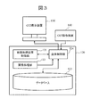
- the computer 120 includes a database 123 and an overall control unit 124 in addition to the image acquisition device control unit 121 and the image processing unit 122.
- the database 123 stores each data table described later.
- the database 123 can be configured by, for example, storing data describing records on each data table in a storage device.
- the overall control unit 124 controls the overall operation of the computer 120.
- the general control unit 124 reads and writes data from and to the database 123, generates a GUI described later, and outputs the generated GUI to the GUI display device 130.
- the overall control unit 124 controls the image acquisition device 110 via the image acquisition device control unit 121 in accordance with a user operation on the GUI.
- FIG. 4 is an example of a screen configuration of the operation screen 401 provided by the computer 120.
- the computer 120 generates the operation screen 401 and outputs it to the GUI display device 130, and the GUI display device 130 displays the operation screen 401 on the screen.
- the operation screen 401 has an observation image display field 402, a toolbar 403, and a layout change button 406.
- the observation image display column 402 displays an observation image of the sample 115 generated by the image processing unit 122.
- the toolbar 403 is a component set in which operation components for calling functions provided in the charged particle beam device 100 are collectively arranged.
- the toolbar 403 further has an all element display button 405. When the all element display button 405 is pressed, it is possible to display the operation components arranged in the toolbar 403 that cannot be displayed on the screen.
- the layout change button 406 When the layout change button 406 is pressed, the computer 120 generates a layout change screen 501 described later with reference to FIG. 5 and outputs it to the GUI display device 130.
- FIG. 5 is an example of a screen configuration of the layout change screen 501.
- the layout change screen 501 includes an all element list 502, a recommended element list 503, and a toolbar list 504.
- the all element list 502 is a list of all operation components that can be arranged on the toolbar 403.
- the recommended element list 503 is a list of operation components that are recommended to be arranged on the toolbar 403. The recommended procedure will be described later.
- the toolbar list 504 is a list of operation components that are determined to be arranged on the toolbar 403.
- the computer 120 stores the operation components on the toolbar list 504 and their arrangement order in the layout database 604, which will be described later, in association with the user-defined name or the name of the sample 115.
- the layout name display unit 508 displays the current user-defined name.
- the computer 120 displays a record of a layout database 604 described later on a screen, and the user can select a desired toolbar layout from the displayed records.
- the toolbar list 504 is replaced by the toolbar layout selected by the user.
- the preview display unit 510 displays, as a preview, the appearance when the operation components on the toolbar list 504 are arranged on the toolbar 403.
- the remaining area display unit 511 displays the size of the part that remains on the toolbar 403 as a surplus area after the operation components on the toolbar list 504 are arranged on the toolbar 403.
- the screen size of the surplus area can be specified by accumulating the bitmap size when the operation components are arranged.
- the user can also perform a keyword search for the operation component using the search box 512.
- the search result can be displayed on the all element list 502 or a pop-up.
- the computer 120 reflects the contents of the toolbar list 504 on the toolbar 403.
- the cancel button 515 the computer ends the layout change screen 501 without reflecting the contents of the toolbar list 504 on the toolbar 403.
- the row optimization button 516 will be described later.
- FIG. 6 is a diagram showing a configuration example of the database 123.
- the database 123 has a sample database 601, a history database 602, a statistics database 603, and a layout database 604.
- the statistical processing unit 605 may be implemented as a function of the database 123 or may be implemented as a functional unit of the computer 120. In the following, the functions of the database 123 are used for convenience. Each database will be described with reference to FIG.
- the statistical processing unit 605 performs a statistical process described below and updates each database.
- FIG. 7 is a diagram showing a configuration example of the sample database 601.
- the sample database 601 has a sample table 701.
- the sample table 701 is a data table holding information on each sample 115, and has a sample name 702 and a thumbnail image 703 as data fields.
- the sample name 702 is a name defined by the user for each sample 115.
- FIG. 8 is a diagram showing a configuration example of the history database 602.
- the history database 602 has a history table 801.
- the history table 801 is a data table that records the history of functions performed by the charged particle beam device 100.
- the functions referred to here are not necessarily limited to those activated via the toolbar 403, but include all functions of the charged particle beam apparatus 100 (or all functions that can be called via the toolbar 403).
- the history table 801 has, as data fields, a sample name 802, date and time 803, function 804, and parameter 805.
- the sample name 802 is the name of the sample 115.
- the date and time 803 is the date when the function was performed, and the function 804 is the function name.
- the parameter 805 is a parameter used when the function 804 is performed. When the function 804 is related to the observation image, an image number 807 described later may be recorded as the parameter 805.
- the history database 602 further has an image history table 806.
- the image history table 806 is a data table that records the history of observation images of the sample 115 acquired by the image acquisition device 110 and the computer 120.
- the image history table 806 has an image number 807, an image 808, and an observation condition 809 as data fields.
- An image number 807 is an identification number of the observation image.
- An image 808 is image data of an observation image.
- the observation conditions 809 are observation conditions (for example, observation magnification, acceleration voltage, and the like) set in the charged particle beam device 100 when the image 808 is acquired.
- FIG. 9 is a diagram showing a configuration example of the statistical database 603.
- the statistical database 603 has a frequency table 901.
- the frequency table 901 is a data table that records the frequency statistics of the functions performed by the charged particle beam apparatus 100, and records a record that totals the history table 801.
- the statistical processing can be performed by the statistical processing unit 605, for example.
- the frequency table 901 has, as data fields, a sample name 902, a function 903, an execution count 904, and a next execution count 905.
- the sample name 902 is the name of the sample 115.
- the function 903 is a function performed by the charged particle beam device 100.
- the number of executions 904 is the total number of times the charged particle beam device 100 has executed the function 903.
- the next execution number 905 is the name of the function executed next after the charged particle beam device 100 has executed the function 903 and the total number of times.
- the functions here are the same as those in the history table 801.
- the statistic database 603 further has an image evaluation value table 906.
- the image evaluation value table 906 is a data table that records a quality evaluation value for each image stored in the image history table 806.
- the quality evaluation value can be calculated by the image processing unit 122 or the statistical processing unit 605, for example.
- the image evaluation value table 906 has a sample name 907, an image number 908, and an evaluation value 909 as data fields.
- the sample name 907 is the name of the sample 115.
- Image number 908 corresponds to image number 807.
- the evaluation value 909 holds the evaluation value for each image quality evaluation item.
- the evaluation items include, for example, sharpness, SN ratio, and contrast. The higher the evaluation value 909, the better the image quality.
- the statistic database 603 further has a necessity table 910.
- the necessity table 910 is a data table that holds the result of calculating the necessity 912 of the function of the charged particle beam device 100 for each sample name 911 and for each function according to the frequency table 901 and the image evaluation value table 906. .
- the necessity 912 can be calculated by the statistical processing unit 605, for example.
- the necessity 912 can be increased as the number of times increases.
- the necessity 912 of the function 903 that can increase the evaluation value 909 may be increased.
- the evaluation value 909 of the sharpness is low, the necessity 912 of the image sharpening function may be relatively higher than other functions.
- the final necessity 912 may be determined by, for example, weighting and adding the necessity calculated based on these criteria.
- FIG. 10 is a diagram showing a configuration example of the layout database 604.
- the layout database 604 has a layout table 1001.
- the layout table 1001 is a data table for recording the layout of the toolbar 403 set by the user on the layout change screen 501.
- the layout table 1001 holds a layout 1003 for each sample name 1002 or user-defined name 1004.
- the layout 1003 here is the arrangement order of the operation components on the toolbar list 504, and corresponds to the arrangement order of the operation components arranged rightward in order from the left end of the toolbar 403.
- the overall control unit 124 can present, on the recommended element list 503, an operation component recommended to be arranged on the toolbar 403 according to the record of the necessity table 910. For example, a record corresponding to the current sample name 911 can be read from the necessity table 910 and placed on the recommended element list 503 in descending order of necessity 912.
- FIG. 11 is an example of a screen configuration of an optimization confirmation screen 1101 presented by the computer 120 when the optimization button 516 is pressed.
- the overall control unit 124 optimizes the arrangement order of the operation components on the toolbar list 504, and displays the result on the optimization confirmation screen 1101.
- the optimization confirmation screen 1101 has a preview 1102 before optimization and a preview 1103 after optimization.
- the pre-optimization preview 1102 is a screen display preview of the toolbar 403 when the operation components are arranged on the toolbar 403 according to the arrangement order of the operation components on the toolbar list 504.
- the post-optimization preview 1103 is a screen display preview of the toolbar 403 after optimizing the arrangement order.
- the overall control unit 124 can optimize the arrangement order of the operation components on the toolbar list 504 according to the record of the statistics database 603. For example, referring to the function 903 and the number of times of next execution 905, if there is a function that is frequently executed next to a certain function 903, they are arranged adjacently on the toolbar 403. For example, in the example of FIG. 9, it can be seen that the frequency at which the function E1 is executed after the function E2 is relatively high. Thus, the amount of operation on the operation screen 401 when executing the functions continuously can be reduced, so that the throughput of the charged particle beam apparatus 100 is improved.
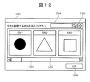
- FIG. 12 is a screen configuration example of the sample change screen 1201.
- the sample change screen 1201 is a screen for notifying the charged particle beam device 100 that the sample 115 has been changed.
- the execution history of the function is recorded for each name of the sample 115, and the functions and the arrangement order on the toolbar 403 are optimized for each name of the sample 115. Therefore, notifying that the sample 115 has been changed is meaningful of instructing the charged particle beam apparatus 100 to perform various processes corresponding to the sample 115 after the change.
- the overall control unit 124 reads the sample name 702 and the thumbnail image 703 from the sample table 701 and displays them on the list 1202. By selecting any sample from the list 1202, the user can notify the charged particle beam apparatus 100 that the sample 115 has been changed to the selected sample. By sliding the scroll bar 1203, other samples that cannot be contained in the list 1202 can be displayed.
- the user can specify the sample name 702 using the search box 1204.
- a record on the sample table 701 corresponding to the specified sample name 702 is displayed on the list 1202.
- the overall control unit 124 adds a record having the sample name 702 entered in the search box 1204 to the sample table 701.
- the OK button 1206 the charged particle beam apparatus 100 is notified that the sample 115 has been changed to the sample selected on the list 1202 (specifically, to the computer 120).
- the charged particle beam device 100 records a history of executing a function in the history database 602, and recommends an operation component to be arranged on the toolbar 403 according to the history. This not only assists the customization of the toolbar 403, but also allows the user to use useful functions of the charged particle beam apparatus 100 that the user is not aware of. Although it is difficult for the user to select a necessary function from a large number of function groups, the first embodiment can effectively support this. By optimizing the operation components on the toolbar 403, the operation efficiency can be improved, so that the throughput of the charged particle beam apparatus 100 can be improved.
- the charged particle beam device 100 recommends an operation component to be arranged on the toolbar 403, instead of designating a function to be continuously executed as a recipe function. Therefore, the user does not necessarily need to execute the functions according to the arrangement order on the toolbar 403, so that the function execution sequence can be changed flexibly. Thereby, it is possible to maintain high versatility while enhancing efficiency by recommending operation components.
- the charged particle beam apparatus 100 can receive a notification that the sample 115 has been changed via the sample change screen 1201.
- the user can visually select a sample.
- the efficiency is improved as compared with the case where the sample is selected by characters, and the time required for selecting the sample can be reduced.
- FIG. 13 is a flowchart illustrating an operation in which the charged particle beam apparatus 100 acquires an observation image of the sample 115 twice.
- the observation position is changed by moving the stage 119 with respect to the same sample 115, and the observation image at each observation position is acquired.
- each step of FIG. 13 will be described.
- Steps S1301 to S1302 The user executes various functions such as setting the observation condition 809 at the current sample 115 and the observation position (S1301).
- the image acquisition device 110 and the computer 120 acquire an observation image of the sample 115 (S1302).
- the user has designated the name of the current sample 115 in step S1301.
- Steps S1303 to S1304 The user moves the stage 119 to change the observation position, and executes various functions as in step S1301 (S1303).
- the image acquisition device 110 and the computer 120 acquire an observation image of the sample 115 at the moved observation position (S1304).
- Step S1305 The user calls the sample change screen 1201 until step S1304 is completed, in view of the fact that step S1304 requires a certain amount of time.
- the user sets a new name of the sample 115 on the sample change screen 1201. For example, a sample name indicating that the observation position has been changed on the same sample is set.
- Step S1305 Supplement
- the target from which an observation image is acquired often changes each time an observation image is acquired once.
- the observation image has already been acquired in step S1302. Therefore, it is considered that the sample name input in this step is intended to be associated with the observation image acquired in step S1304 as the user.
- the computer 120 performs the following steps accordingly.
- a confirmation dialog as illustrated in FIG. 14 described later may be displayed.
- Step S1306 When the functions performed during steps S1303 to S1305 are recorded in the history table 801, the general control unit 124 replaces the sample name 802 in those records with the sample name input in step S1305. This is because these functions are performed on the sample corresponding to step S1304.
- Steps S1307 to S1308 The overall control unit 124 records the observation images acquired so far in the image history table 806 (S1307), and updates each table in the statistical database 603 (S1308).
- FIG. 14 is an example of a screen configuration when a confirmation dialog is displayed in step S1305.
- the confirmation dialog 1401 has a change button 1402 and a cancel button 1403. If the user presses the change button 1402, steps S1306 and subsequent steps are performed. If the user presses the cancel button 1403, step S1306 is skipped, and step S1307 and subsequent steps are performed.
- the time required for acquiring an observation image can be effectively used. Specifically, in order to obtain an observation image, it is necessary to integrate signals from the detector 117 and perform various image processing for obtaining a low-noise image. Since these processes require a certain amount of time, the second embodiment can effectively utilize the time.
- the image acquisition device 110 evacuates the sample chamber by the exhaust device 111.
- the evacuation is a function that requires a certain amount of time, and more time is required depending on the performance of the exhaust device 111.
- an operation example in which the user performs various operations on the screen using the exhaust time will be described.
- the configuration of the charged particle beam device 100 is the same as that of the first embodiment.
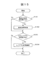
- FIG. 15 is a flowchart illustrating an operation procedure when the charged particle beam device 100 evacuates the sample chamber.
- the computer 120 starts this flowchart.
- each step of FIG. 15 will be described.
- Step S1501 The computer 120 displays a dialog similar to the confirmation dialog 1401 on the screen. This step is meaningful for prompting the user to confirm whether or not the sample name currently used by the computer 120 corresponds to the actual sample 115. If the user presses the change button, the process advances to step S1502; if the user presses the cancel button, the process skips to step S1503.
- Step S1502 The computer 120 displays a sample change screen 1201 on the screen. The user changes the sample name on the screen.
- Step S1503 The computer 120 displays a confirmation dialog 1601 described later with reference to FIG. 16 on a screen. If the user presses the change button on the dialog, the process advances to step S1504. If the user presses the cancel button, the process ends.
- the computer 120 displays a layout change screen 501 on the screen.
- the user changes the operation components to be arranged on the toolbar 403 on the same screen.
- the computer 120 can also recommend operation components to be arranged on the toolbar 403 on the screen.
- FIG. 16 shows an example of the screen configuration of the confirmation dialog 1601 displayed in step S1503.
- the confirmation dialog 1601 has a change button 1602 and a cancel button 1603.
- the time required for evacuating the sample chamber can be effectively used. Since the evacuation of the sample chamber is often performed when the sample 115 is exchanged, it is necessary to change the sample name and the layout of the toolbar 403 accordingly. By performing this during the evacuation time, the standby time for evacuation can be effectively utilized.
- the present invention is not limited to the embodiments described above, and includes various modifications.
- the above-described embodiments have been described in detail for easy understanding of the present invention, and are not necessarily limited to those having all the configurations described above.
- a part of the configuration of one embodiment can be replaced with the configuration of another embodiment, and the configuration of one embodiment can be added to the configuration of another embodiment.
- each device does not need to be implemented as a separate device, and may be implemented by a device having a plurality of functions or a combination thereof.
- the GUI display device 130 and the GUI operation device 140 may be implemented by a device having both a display function and an operation function, such as a touch panel.
- the database 123 may be held inside the computer 120, or the database may be configured on an external storage device and used by the computer 120.
- the operation component of the toolbar 403 may be of any type as long as the function of the charged particle beam device 100 can be called.
- a button, a slider, a check box, a text box, and the like can be considered.
- the component set included in the operation screen 401 is not necessarily limited to the toolbar, and may be, for example, a panel or tab in which operation components are aggregated. That is, when the display area size on the operation screen 401 is limited, the present invention can be applied as long as the operation components to be displayed on the screen are selected in accordance with the history.
- the sample name is changed when the observation image is obtained.
- the same processing can be performed in other types of charged particle beam devices.
- FIB Flucused Ion Beam
- the sample name after the change is considered to correspond to the second FIB irradiation. Therefore, in FIG. 13, the same operation as in the second embodiment can be performed by replacing the observation image acquisition step with FIB irradiation.
- the above-described configurations, functions, processing units, processing means, and the like may be partially or entirely realized by hardware, for example, by designing an integrated circuit.
- the above-described configurations, functions, and the like may be realized by software by a processor interpreting and executing a program that realizes each function.
- Information such as a program, a table, and a file for realizing each function can be stored in a memory, a hard disk, a recording device such as an SSD (Solid State Drive), or a recording medium such as an IC card or an SD card.
- control lines and information lines are shown as necessary for the description, and do not necessarily indicate all control lines and information lines on a product. In fact, it can be considered that almost all components are connected to each other.
- GUI display device 140 GUI operation device 403: Toolbar 502: All element list 503: Recommended element list 504: Toolbar list 510: Preview display unit 511: Rest Size display section 516: Alignment optimization button 601: Sample database 602: History database 603: Statistics database 604: Layout database 605: Statistics processing section
Landscapes
- Chemical & Material Sciences (AREA)
- Analytical Chemistry (AREA)
- Testing Or Measuring Of Semiconductors Or The Like (AREA)
- User Interface Of Digital Computer (AREA)
Abstract
本発明は、ユーザにとって必要な機能をGUI上で簡単かつ迅速に呼び出すことができる荷電粒子線装置を提供することを目的とする。本発明に係る荷電粒子線装置は、前記荷電粒子線装置の動作履歴にしたがって、コンポーネントセット上に配置することを推奨する操作コンポーネントを提示する(図5参照)。
Description
本発明は、荷電粒子線装置に関する。
荷電粒子線装置は、試料に対して実施する機能を組み合わせることにより、様々な動作を実施することができる。このときの観察条件などのパラメータは、レシピなどと呼ばれる。最適なレシピを作成するためには、試行錯誤を要するのが一般的である。これに対して、レシピを効率的に作成することを支援する技術が開発されている。
下記特許文献1は、観察装置のレシピについて記載している。同文献は、『観察装置において、初心者であっても、試行錯誤することなく、既存のレシピ設定内容を解析でき、解析結果に基づき、新規のレシピを短時間で作成できるレシピ設定方法、および観察装置を提供する。』ことを課題として、『観察条件を登録したレシピに基づき、登録した観察条件で試料の観察を行う機能を有する観察装置であって、複数のレシピを対象として、複数の設定項目の設定内容を一覧形式で表示し、共通性を解析した結果に基づき、共通性が高い設定内容を初期設定として、新たなレシピを作成することを主要な特徴とする。』という技術を開示している(要約参照)。
特許文献1記載の技術によれば、最適なレシピを効率的に作成することができる。他方で荷電粒子線装置を使用するユーザは、手動または半自動により様々な機能を実施することにより、臨機応変に観察条件や観察箇所を設定する場合がある。この場合、ユーザは必ずしもレシピにしたがって機能を実施するわけではなく、例えばグラフィカル・ユーザ・インターフェース(GUI)を通して、手動により様々な機能を呼び出す。
しかしながら、荷電粒子線装置が備える機能は多様にわたっているので、それら全ての機能をGUI上に表示すると、画面構成が煩雑となり、所望の機能をGUI上で探すことが困難となる。複数の機能を階層的に整理して表示することも考えられるが、この場合は所望の機能にたどり着くまでのGUI上における操作が煩雑になるだけでなく、荷電粒子線装置が実行可能な機能の存在にユーザが気づけない恐れもある。一方で、GUI上に表示する機能の種類を制限してしまうと、GUI経由で所望の機能を実行できなくなる可能性があり、荷電粒子線装置の汎用性が低下する。
本発明は、上記のような課題に鑑みてなされたものであり、ユーザにとって必要な機能をGUI上で簡単かつ迅速に呼び出すことができる荷電粒子線装置を提供することを目的とする。
本発明に係る荷電粒子線装置は、前記荷電粒子線装置の動作履歴にしたがって、コンポーネントセット上に配置することを推奨する操作コンポーネントを提示する。
本発明に係る荷電粒子線装置によれば、ユーザにとって有用な機能を効率的に呼び出すことができることに加え、ユーザにとって有用性が低い機能を表示しないシンプルなGUIを提供することができる。これにより、荷電粒子線装置を用いた作業のスループットを向上させることができる。
<実施の形態1>
図1は、本発明の実施形態1に係る荷電粒子線装置100の構成図である。荷電粒子線装置100は、試料に対して荷電粒子線を照射する装置である。以下では例えば走査電子顕微鏡(SEM)のように、試料に対して荷電粒子線を照射することにより、試料の観察画像を取得する装置を例として説明する。
図1は、本発明の実施形態1に係る荷電粒子線装置100の構成図である。荷電粒子線装置100は、試料に対して荷電粒子線を照射する装置である。以下では例えば走査電子顕微鏡(SEM)のように、試料に対して荷電粒子線を照射することにより、試料の観察画像を取得する装置を例として説明する。
荷電粒子線装置100は、画像取得装置110、コンピュータ120、GUI表示装置130、GUI操作装置140を有する。画像取得装置110は、試料に対して荷電粒子線を照射する装置(例えばSEM)である。コンピュータ120は、ユーザが荷電粒子線装置100を操作するために用いるGUIを生成し、GUI表示装置130に対して出力する。GUI表示装置130は、例えばディスプレイデバイスであり、GUIを画面表示する。GUI操作装置140は、例えばキーボードやマウスなどのように、コンピュータ120を操作するためユーザが用いるデバイスである。
図2は、画像取得装置110の構成とコンピュータ120との接続を表した図である。荷電粒子銃112は、荷電粒子線113を発生させる。荷電粒子線113は、レンズ114を通過することにより、試料115に収束する。レンズ114は例えば、荷電粒子線を偏向させる荷電粒子レンズ、荷電粒子線を収束させる荷電粒子レンズ、荷電粒子線の非点収差を補正するための荷電粒子レンズ、またはそれらの組み合わせである。
検出器117は、荷電粒子線113を試料115に対して照射することにより生じる荷電粒子116を検出し、その検出結果(例えば2次電子の信号強度)を表す検出結果をコンピュータ120に対して出力する。コンピュータ120(画像処理部122)は、その検出結果を用いて、試料115の観察画像を生成する。検出器117は、荷電粒子を検出するのみでなく、電磁波や光を検出する検出器であってもよい。さらに複数の検出器によって構成してもよい。
ステージ119は、試料115を載置する。ステージ119を移動させることにより、試料115の観察位置を変更することができる。排気装置111は、試料115とステージ119を収容する試料室内を真空排気することにより、試料室内の真空度を調整する。
コンピュータ120は、画像取得装置制御部121と画像処理部122を備える。画像取得装置制御部121は、画像取得装置110の動作を制御する。例えば排気装置111、荷電粒子銃112、レンズ114、ステージ119を制御する。
図3は、コンピュータ120の構成図である。コンピュータ120は、画像取得装置制御部121と画像処理部122に加えて、データベース123と全体制御部124を備える。データベース123は、後述する各データテーブルを格納する。データベース123は例えば、各データテーブル上のレコードを記述したデータを記憶装置に格納することによって構成することができる。全体制御部124は、コンピュータ120の全体動作を制御する。全体制御部124は、データベース123との間でデータを読み書きし、後述するGUIを生成してGUI表示装置130に対して出力する。全体制御部124は、画像取得装置制御部121を介して、GUI上におけるユーザの操作にしたがって、画像取得装置110を制御する。
図4は、コンピュータ120が提供する操作画面401の画面構成例である。コンピュータ120は、操作画面401を生成してGUI表示装置130に対して出力し、GUI表示装置130は操作画面401を画面表示する。操作画面401は、観察画像表示欄402、ツールバー403、レイアウト変更ボタン406を有する。
観察画像表示欄402は、画像処理部122が生成した試料115の観察画像を表示する。ツールバー403は、荷電粒子線装置100が備える機能を呼び出すための操作コンポーネントを集約して配置したコンポーネントセットである。ツールバー403はさらに全要素表示ボタン405を有する。全要素表示ボタン405が押下されると、ツールバー403内に配置されている操作コンポーネントのうち、画面上に表示しきれないものを表示することができる。レイアウト変更ボタン406が押下されると、コンピュータ120は後述の図5で説明するレイアウト変更画面501を生成してGUI表示装置130へ出力する。
図5は、レイアウト変更画面501の画面構成例である。レイアウト変更画面501は、全要素リスト502、オススメ要素リスト503、ツールバーリスト504を有する。全要素リスト502は、ツールバー403上に配置することができる全ての操作コンポーネントのリストである。オススメ要素リスト503は、ツールバー403上に配置することを推奨する操作コンポーネントのリストである。推奨手順については後述する。ツールバーリスト504は、ツールバー403上に配置することを決定した操作コンポーネントのリストである。
ユーザは、全要素リスト502とオススメ要素リスト503それぞれにおいて、ツールバー403上に配置する操作コンポーネントを選択し、追加ボタン505を押下する。これにより、選択されている操作コンポーネントがツールバーリスト504に追加される。ユーザが削除ボタン506を押下すると、ツールバーリスト504上で選択されている操作コンポーネントがツールバーリスト504から削除される。これらボタンに代えてマウスのドラッグ&ドロップによって同様の操作を実施してもよい。各リスト上の表示位置はスクロールバー507によって変更することができる。各リスト上の操作コンポーネントの並び順は、ドラッグ&ドロップによって変更することができる。
ユーザが保存ボタン513を押下すると、コンピュータ120はツールバーリスト504上の操作コンポーネントとその並び順を、ユーザ定義名または試料115の名称と関連付けて、後述するレイアウトデータベース604に格納する。レイアウト名表示部508は、現在のユーザ定義名を表示する。
ユーザがレイアウト呼び出しボタン509を押下すると、コンピュータ120は後述するレイアウトデータベース604のレコードを画面表示し、ユーザはそのなかから所望のツールバーレイアウトを選択することができる。ツールバーリスト504は、ユーザが選択したツールバーレイアウトによって置き換えられる。
プレビュー表示部510は、ツールバーリスト504上の操作コンポーネントをツールバー403上に配置したときの外観をプレビューとして表示する。残り広さ表示部511は、ツールバーリスト504上の操作コンポーネントをツールバー403上に配置した上でなお余剰領域としてツールバー403上に残っている部分のサイズを表示する。余剰領域の画面サイズは、操作コンポーネントを配置したときのビットマップサイズを累積することによって特定することができる。ユーザは検索ボックス512を用いて操作コンポーネントをキーワード検索することもできる。検索結果は全要素リスト502もしくはポップアップに表示することができる。
ユーザがOKボタン514を押下すると、コンピュータ120はツールバーリスト504の内容をツールバー403に反映する。ユーザがキャンセルボタン515を押下すると、コンピュータはツールバーリスト504の内容をツールバー403に反映しないでレイアウト変更画面501を終了する。並びの最適化ボタン516については後述する。
図6は、データベース123の構成例を示す図である。データベース123は、試料データベース601、履歴データベース602、統計データベース603、レイアウトデータベース604を有する。統計処理部605は、データベース123の機能として実装してもよいし、コンピュータ120の機能部として実装してもよい。以下では便宜上、データベース123の機能とする。各データベースについては図7以降で説明する。統計処理部605は、後述する統計処理を実施して各データベースを更新する。
図7は、試料データベース601の構成例を示す図である。試料データベース601は試料テーブル701を有する。試料テーブル701は、各試料115についての情報を保持するデータテーブルであり、データフィールドとして試料名702とサムネイル画像703を有する。試料名702は、各試料115についてユーザが定義した名称である。サムネイル画像703としては、後述する観察画像のうち例えば最も画像品質がよいものを選択することができる。具体的には、後述する評価値909が総合的に最も高いものを選択すればよい。
図8は、履歴データベース602の構成例を示す図である。履歴データベース602は履歴テーブル801を有する。履歴テーブル801は、荷電粒子線装置100が実施した機能の履歴を記録するデータテーブルである。ここでいう機能は、必ずしもツールバー403を介して起動されたものに限られず、荷電粒子線装置100が備える全ての機能(あるいはツールバー403を経由して呼び出すことができる全ての機能)である。
履歴テーブル801はデータフィールドとして、試料名802、日時803、機能804、パラメータ805を有する。試料名802は、試料115の名称である。日時803は機能を実施した年月日時刻であり、機能804はその機能名である。パラメータ805は、機能804を実施する際のパラメータである。機能804が観察画像に関連するものである場合、後述する画像番号807をパラメータ805として記録してもよい。
履歴データベース602はさらに、画像履歴テーブル806を有する。画像履歴テーブル806は、画像取得装置110とコンピュータ120が取得した試料115の観察画像の履歴を記録するデータテーブルである。画像履歴テーブル806はデータフィールドとして、画像番号807、画像808、観察条件809を有する。画像番号807は観察画像の識別番号である。画像808は観察画像の画像データである。観察条件809は、画像808を取得したとき荷電粒子線装置100にセットした観察条件(例えば観察倍率や加速電圧など)である。
図9は、統計データベース603の構成例を示す図である。統計データベース603は頻度テーブル901を有する。頻度テーブル901は、荷電粒子線装置100が実施した機能の頻度統計を記録するデータテーブルであり、履歴テーブル801を集計したレコードを記録する。統計処理は例えば統計処理部605が実施することができる。
頻度テーブル901はデータフィールドとして、試料名902、機能903、実行回数904、次実行回数905を有する。試料名902は試料115の名称である。機能903は荷電粒子線装置100が実施した機能である。実行回数904は、荷電粒子線装置100が機能903を実行した合計回数である。次実行回数905は、荷電粒子線装置100が機能903を実行した次に実行した機能の名称と合計回数である。ここでいう機能は履歴テーブル801におけるものと同様である。
統計データベース603はさらに、画像評価値テーブル906を有する。画像評価値テーブル906は、画像履歴テーブル806が保持している画像ごとに、品質評価値を記録するデータテーブルである。品質評価値は、例えば画像処理部122または統計処理部605が算出することができる。
画像評価値テーブル906はデータフィールドとして、試料名907、画像番号908、評価値909を有する。試料名907は試料115の名称である。画像番号908は画像番号807に対応する。評価値909は、画像品質の評価項目ごとにその評価値を保持する。評価項目としては例えばシャープネス、SN比、コントラストなどが挙げられる。評価値909が高いほど画像品質がよいことを表している。
統計データベース603はさらに、必要度テーブル910を有する。必要度テーブル910は、荷電粒子線装置100が備える機能の必要度912を、頻度テーブル901と画像評価値テーブル906にしたがって、試料名911ごとかつ機能ごとに算出した結果を保持するデータテーブルである。必要度912は例えば統計処理部605が算出することができる。
必要度912を算出する基準として、例えば以下のようなものが考えられる。実行回数904が多い機能903は必要度が高いと考えられるので、その回数が多いほど必要度912を高くすることができる。これとは別に、評価値909のなかで特に値が低いものについては、その評価値909を上げることができる機能903の必要度912を高くしてもよい。例えばシャープネスの評価値909が低ければ、画像鮮明化機能の必要度912を他の機能よりも相対的に高くしてもよい。これらの基準によって算出した必要度を例えば重み付け加算することにより、最終的な必要度912を決定してもよい。
図10は、レイアウトデータベース604の構成例を示す図である。レイアウトデータベース604は、レイアウトテーブル1001を有する。レイアウトテーブル1001はレイアウト変更画面501上でユーザがセットしたツールバー403のレイアウトを記録するデータテーブルである。レイアウトテーブル1001は、試料名1002またはユーザ定義名1004ごとに、レイアウト1003を保持する。ここでいうレイアウト1003は、ツールバーリスト504上における操作コンポーネントの並び順であり、ツールバー403の左端から順に右側に向かって配置する操作コンポーネントの配置順に相当するものである。
<実施の形態1:ツールバーに配置する機能の提案>
全体制御部124は、必要度テーブル910のレコードにしたがって、ツールバー403に配置することを推奨する操作コンポーネントを、オススメ要素リスト503上に提示することができる。例えば現在の試料名911に対応するレコードを必要度テーブル910から読み出し、必要度912が高い順にオススメ要素リスト503上に配置することができる。
全体制御部124は、必要度テーブル910のレコードにしたがって、ツールバー403に配置することを推奨する操作コンポーネントを、オススメ要素リスト503上に提示することができる。例えば現在の試料名911に対応するレコードを必要度テーブル910から読み出し、必要度912が高い順にオススメ要素リスト503上に配置することができる。
<実施の形態1:並びの最適化>
図11は、並びの最適化ボタン516が押下されたときコンピュータ120が提示する最適化確認画面1101の画面構成例である。並びの最適化ボタン516が押下されると、全体制御部124はツールバーリスト504上の操作コンポーネントの並び順を最適化し、その結果を最適化確認画面1101上に表示する。
図11は、並びの最適化ボタン516が押下されたときコンピュータ120が提示する最適化確認画面1101の画面構成例である。並びの最適化ボタン516が押下されると、全体制御部124はツールバーリスト504上の操作コンポーネントの並び順を最適化し、その結果を最適化確認画面1101上に表示する。
最適化確認画面1101は、最適化前プレビュー1102、最適化後プレビュー1103を有する。最適化前プレビュー1102は、ツールバーリスト504上の操作コンポーネントの並び順にしたがってツールバー403上に操作コンポーネントを配置したときのツールバー403の画面表示プレビューである。最適化後プレビュー1103は、並び順を最適化した後のツールバー403の画面表示プレビューである。ユーザがOKボタン1104を押下した場合は、最適化後プレビュー1103の並び順をツールバー403に対して反映し、ユーザがキャンセルボタン1105を押下した場合は反映しない。
全体制御部124は、統計データベース603のレコードにしたがって、ツールバーリスト504上の操作コンポーネントの並び順を最適化することができる。例えば、機能903と次実行回数905を参照し、ある機能903の次に連続して実行される頻度が高い機能が存在する場合は、ツールバー403上でそれらを隣接して配置する。例えば図9の例においては、機能E2の次に機能E1が実行される頻度が相対的に高いことが分かる。これにより、機能を連続して実行する際における操作画面401上の操作量を減らすことができるので、荷電粒子線装置100のスループットが向上する。
<実施の形態1:試料変更>
図12は、試料変更画面1201の画面構成例である。試料変更画面1201は、試料115を変更したことを荷電粒子線装置100に対して通知するための画面である。本実施形態1においては、試料115の名称ごとに機能の実行履歴を記録し、さらには試料115の名称ごとにツールバー403上に配置する機能と並び順を最適化する。したがって試料115を変更したことを通知するのは、変更後の試料115に対応する各種処理を実施するように、荷電粒子線装置100に対して指示する意義がある。
図12は、試料変更画面1201の画面構成例である。試料変更画面1201は、試料115を変更したことを荷電粒子線装置100に対して通知するための画面である。本実施形態1においては、試料115の名称ごとに機能の実行履歴を記録し、さらには試料115の名称ごとにツールバー403上に配置する機能と並び順を最適化する。したがって試料115を変更したことを通知するのは、変更後の試料115に対応する各種処理を実施するように、荷電粒子線装置100に対して指示する意義がある。
全体制御部124は、試料テーブル701から試料名702とサムネイル画像703を読み出し、リスト1202上に表示する。ユーザはリスト1202からいずれかの試料を選択することにより、試料115をその選択した試料へ変更したことを、荷電粒子線装置100に対して通知することができる。スクロールバー1203をスライドさせることにより、リスト1202に収まりきらないその他試料を表示することができる。
ユーザは検索ボックス1204を用いて試料名702を指定することができる。指定した試料名702に対応する試料テーブル701上のレコードが、リスト1202上に表示される。ユーザが追加ボタン1205を押下すると、全体制御部124は、検索ボックス1204に入力されている試料名702を有するレコードを試料テーブル701に対して追加する。ユーザがOKボタン1206を押下すると、試料115をリスト1202上で選択されている試料に変更した旨を、荷電粒子線装置100に対して(具体的にはコンピュータ120に対して)通知する。
<実施の形態1:まとめ>
本実施形態1に係る荷電粒子線装置100は、機能を実行した履歴を履歴データベース602に記録しておき、その履歴にしたがって、ツールバー403に配置する操作コンポーネントを推奨する。これにより、ツールバー403のカスタマイズをアシストするだけでなく、ユーザが気づいていない荷電粒子線装置100の有用な機能を利用できるようにすることができる。多数の機能群のなかからユーザ自身にとって必要なものを選択するのは困難であるが、本実施形態1によりこれを効果的に支援することができる。ツールバー403上の操作コンポーネントを最適化することにより、操作効率を高めることにつながるので、荷電粒子線装置100のスループットを向上させることもできる。
本実施形態1に係る荷電粒子線装置100は、機能を実行した履歴を履歴データベース602に記録しておき、その履歴にしたがって、ツールバー403に配置する操作コンポーネントを推奨する。これにより、ツールバー403のカスタマイズをアシストするだけでなく、ユーザが気づいていない荷電粒子線装置100の有用な機能を利用できるようにすることができる。多数の機能群のなかからユーザ自身にとって必要なものを選択するのは困難であるが、本実施形態1によりこれを効果的に支援することができる。ツールバー403上の操作コンポーネントを最適化することにより、操作効率を高めることにつながるので、荷電粒子線装置100のスループットを向上させることもできる。
本実施形態1に係る荷電粒子線装置100は、レシピ機能のように連続実行する機能を指定するのではなく、ツールバー403上に配置する操作コンポーネントを推奨するものである。したがって、ユーザは必ずしもツールバー403上の並び順にしたがって機能を実行する必要はないので、臨機応変に機能実行シーケンスを変更することができる。これにより、操作コンポーネントを推奨することにより効率性を高めつつ、高い汎用性を維持することができる。
本実施形態1に係る荷電粒子線装置100は、試料変更画面1201を介して、試料115を変更した旨の通知を受け取ることができる。したがってユーザは、試料を視覚的に選択することができる。これにより、文字で試料を選択するよりも効率が向上するので、試料選択に掛かる時間を短縮できる。
<実施の形態2>
画像取得装置110とコンピュータ120が、試料115の観察画像を取得するためには、ある程度の処理時間が必要となる場合がある。本発明の実施形態2では、この処理時間を利用して、ユーザが画面上で様々な操作を実施する動作例を説明する。荷電粒子線装置100の構成は実施形態1と同様である。
画像取得装置110とコンピュータ120が、試料115の観察画像を取得するためには、ある程度の処理時間が必要となる場合がある。本発明の実施形態2では、この処理時間を利用して、ユーザが画面上で様々な操作を実施する動作例を説明する。荷電粒子線装置100の構成は実施形態1と同様である。
図13は、荷電粒子線装置100が試料115の観察画像を2回取得する動作を説明するフローチャートである。ここでは同じ試料115に対して、ステージ119を移動させて観察位置を変更し、各観察位置における観察画像をそれぞれ取得する場面を想定する。以下図13の各ステップについて説明する。
(図13:ステップS1301~S1302)
ユーザは、現在の試料115および観察位置において、観察条件809をセットするなど各種機能を実行する(S1301)。画像取得装置110とコンピュータ120は、試料115の観察画像を取得する(S1302)。ここではステップS1301のなかで、現在の試料115の名称をユーザが指定したものと仮定する。
ユーザは、現在の試料115および観察位置において、観察条件809をセットするなど各種機能を実行する(S1301)。画像取得装置110とコンピュータ120は、試料115の観察画像を取得する(S1302)。ここではステップS1301のなかで、現在の試料115の名称をユーザが指定したものと仮定する。
(図13:ステップS1303~S1304)
ユーザは、ステージ119を移動させて観察位置を変更し、ステップS1301と同様に各種機能を実行する(S1303)。画像取得装置110とコンピュータ120は、移動後の観察位置において試料115の観察画像を取得する(S1304)。
ユーザは、ステージ119を移動させて観察位置を変更し、ステップS1301と同様に各種機能を実行する(S1303)。画像取得装置110とコンピュータ120は、移動後の観察位置において試料115の観察画像を取得する(S1304)。
(図13:ステップS1305)
ユーザは、ステップS1304がある程度の時間を必要とすることに鑑みて、ステップS1304が完了するまでの間において、試料変更画面1201を呼び出す。ユーザは試料変更画面1201上において、試料115の新たな名称をセットする。例えば同じ試料上において観察位置を変更した旨を表す試料名をセットする。
ユーザは、ステップS1304がある程度の時間を必要とすることに鑑みて、ステップS1304が完了するまでの間において、試料変更画面1201を呼び出す。ユーザは試料変更画面1201上において、試料115の新たな名称をセットする。例えば同じ試料上において観察位置を変更した旨を表す試料名をセットする。
(図13:ステップS1305:補足)
一般に観察画像を取得する対象は、観察画像を1回取得するごとに変更することが多いといえる。本フローチャートにおいては、ステップS1302において既に観察画像を取得済である。したがって本ステップにおいて入力した試料名は、ユーザとしてはステップS1304において取得する観察画像に対応付けることを意図していると考えられる。コンピュータ120はこれにしたがって以下のステップを実行する。本ステップにおいて、後述の図14で例示するような確認ダイアログを表示してもよい。
一般に観察画像を取得する対象は、観察画像を1回取得するごとに変更することが多いといえる。本フローチャートにおいては、ステップS1302において既に観察画像を取得済である。したがって本ステップにおいて入力した試料名は、ユーザとしてはステップS1304において取得する観察画像に対応付けることを意図していると考えられる。コンピュータ120はこれにしたがって以下のステップを実行する。本ステップにおいて、後述の図14で例示するような確認ダイアログを表示してもよい。
(図13:ステップS1306)
全体制御部124は、ステップS1303~S1305の間に実施した機能について履歴テーブル801に記録した場合は、それらのレコードのうち試料名802について、ステップS1305で入力した試料名に置き換える。これらの機能はステップS1304に対応する試料に対して実施されたものだからである。
全体制御部124は、ステップS1303~S1305の間に実施した機能について履歴テーブル801に記録した場合は、それらのレコードのうち試料名802について、ステップS1305で入力した試料名に置き換える。これらの機能はステップS1304に対応する試料に対して実施されたものだからである。
(図13:ステップS1307~S1308)
全体制御部124は、これまで取得した観察画像を画像履歴テーブル806に記録し(S1307)、統計データベース603の各テーブルを更新する(S1308)。
全体制御部124は、これまで取得した観察画像を画像履歴テーブル806に記録し(S1307)、統計データベース603の各テーブルを更新する(S1308)。
図14は、ステップS1305において確認ダイアログを表示する場合における画面構成例である。確認ダイアログ1401は、変更ボタン1402とキャンセルボタン1403を有する。ユーザが変更ボタン1402を押下した場合はステップS1306以降を実施する。ユーザがキャンセルボタン1403を押下した場合はステップS1306をスキップし、ステップS1307以降を実施する。
本実施形態2によれば、観察画像を取得するために必要な時間を有効活用することができる。具体的には、観察画像を取得するためには、検出器117の信号を積算し、低ノイズの画像を取得するための様々な画像処理を実施する必要がある。これらの処理はある程度の時間を必要とするので、本実施形態2によってその時間を有効活用できる。
<実施の形態3>
画像取得装置110は、排気装置111によって試料室を真空排気する。真空排気はある程度の時間を要する機能であり、また排気装置111の性能によってはさらに多くの時間を必要とする。本発明の実施形態3では、その排気時間を用いて、ユーザが画面上で様々な操作を実施する動作例を説明する。荷電粒子線装置100の構成は実施形態1と同様である。
画像取得装置110は、排気装置111によって試料室を真空排気する。真空排気はある程度の時間を要する機能であり、また排気装置111の性能によってはさらに多くの時間を必要とする。本発明の実施形態3では、その排気時間を用いて、ユーザが画面上で様々な操作を実施する動作例を説明する。荷電粒子線装置100の構成は実施形態1と同様である。
図15は、荷電粒子線装置100が試料室を真空排気する際の動作手順を説明するフローチャートである。排気装置111が真空排気を開始すると、コンピュータ120は本フローチャートを開始する。以下図15の各ステップについて説明する。
(図15:ステップS1501)
コンピュータ120は、確認ダイアログ1401と同様のダイアログを画面表示する。本ステップは、コンピュータ120が現在用いている試料名と、実際の試料115とが対応しているか否かを、ユーザが確認するように促す意義がある。ユーザが変更ボタンを押下した場合はステップS1502へ進み、キャンセルボタンを押下した場合はステップS1503へスキップする。
コンピュータ120は、確認ダイアログ1401と同様のダイアログを画面表示する。本ステップは、コンピュータ120が現在用いている試料名と、実際の試料115とが対応しているか否かを、ユーザが確認するように促す意義がある。ユーザが変更ボタンを押下した場合はステップS1502へ進み、キャンセルボタンを押下した場合はステップS1503へスキップする。
(図15:ステップS1502)
コンピュータ120は、試料変更画面1201を画面表示する。ユーザは同画面上で試料名を変更する。
コンピュータ120は、試料変更画面1201を画面表示する。ユーザは同画面上で試料名を変更する。
(図15:ステップS1503)
コンピュータ120は、後述の図16で説明する確認ダイアログ1601を画面表示する。ユーザが同ダイアログ上で変更ボタンを押下した場合はステップS1504へ進み、キャンセルボタンを押下した場合は本フローチャートを終了する。
コンピュータ120は、後述の図16で説明する確認ダイアログ1601を画面表示する。ユーザが同ダイアログ上で変更ボタンを押下した場合はステップS1504へ進み、キャンセルボタンを押下した場合は本フローチャートを終了する。
(図15:ステップS1504)
コンピュータ120は、レイアウト変更画面501を画面表示する。ユーザは同画面上でツールバー403に配置する操作コンポーネントを変更する。コンピュータ120は同画面上において、ツールバー403に配置する操作コンポーネントを推奨することもできる。
コンピュータ120は、レイアウト変更画面501を画面表示する。ユーザは同画面上でツールバー403に配置する操作コンポーネントを変更する。コンピュータ120は同画面上において、ツールバー403に配置する操作コンポーネントを推奨することもできる。
図16は、ステップS1503において表示する確認ダイアログ1601の画面構成例である。確認ダイアログ1601は、変更ボタン1602とキャンセルボタン1603を有する。
本実施形態3によれば、試料室を真空排気するために必要な時間を有効活用することができる。試料室を真空排気するのは、試料115を交換するタイミングであることが多いので、これにともなって試料名とツールバー403のレイアウトを変更する必要がある。真空排気時間中にこれを実施することにより、真空排気のための待機時間を有効に活用することができる。
<本発明の変形例について>
本発明は、前述した実施形態に限定されるものではなく、様々な変形例が含まれる。例えば、上記した実施形態は本発明を分かりやすく説明するために詳細に説明したものであり、必ずしも説明した全ての構成を備えるものに限定されるものではない。また、ある実施形態の構成の一部を他の実施形態の構成に置き換えることが可能であり、また、ある実施形態の構成に他の実施形態の構成を加えることも可能である。また、各実施形態の構成の一部について、他の構成の追加・削除・置換をすることが可能である。
本発明は、前述した実施形態に限定されるものではなく、様々な変形例が含まれる。例えば、上記した実施形態は本発明を分かりやすく説明するために詳細に説明したものであり、必ずしも説明した全ての構成を備えるものに限定されるものではない。また、ある実施形態の構成の一部を他の実施形態の構成に置き換えることが可能であり、また、ある実施形態の構成に他の実施形態の構成を加えることも可能である。また、各実施形態の構成の一部について、他の構成の追加・削除・置換をすることが可能である。
以上の実施形態において、各装置をそれぞれ別装置として実装する必要はなく、複数の機能を備えた装置またはその組み合わせによって実施されてもよい。例えばGUI表示装置130とGUI操作装置140は、タッチパネルのように表示機能と操作機能を兼ね備えた装置によって実装してもよい。
以上の実施形態において、データベース123はコンピュータ120の内部に保持していてもよいし、外部記憶装置上にデータベースを構成してコンピュータ120がそれを利用してもよい。
ツールバー403が備える操作コンポーネントは、荷電粒子線装置100が備える機能を呼び出すことができるものであれば、種別は問わない。例えばボタン、スライダ、チェックボックス、テキストボックス、などが考えられる。また操作画面401が備えるコンポーネントセットは、必ずしもツールバーに限られるものではなく、例えば操作コンポーネントを集約したパネルやタブなどの形態であってもよい。すなわち、操作画面401上における表示エリアサイズが限られている場合において、画面表示する操作コンポーネントを履歴にしたがって選択する限りにおいて、本発明を適用することができる。
以上の実施形態においては、試料115に対して電子線を照射することにより観察画像を取得する構成例を説明したが、その他タイプの荷電粒子線装置においても、ツールバー403上に配置する操作コンポーネントについて本発明を適用することができる。
実施形態2において、観察画像を取得する際に試料名を変更することを説明したが、その他タイプの荷電粒子線装置においても同様の処理を実施することができる。例えばFIB(Focused Ion Beam)装置であれば、試料115に対してFIBを照射してから、次にFIBを照射するまでの間に、何らかの機能を実施した上で試料名を変更した場合、その変更後の試料名は、2回目のFIB照射に対応していると考えられる。したがって図13において、観察画像取得のステップをFIB照射に置き換えれば、実施形態2と同様の動作を実施できる。
上記の各構成、機能、処理部、処理手段等は、それらの一部又は全部を、例えば集積回路で設計する等によりハードウェアで実現してもよい。また、上記の各構成、機能等は、プロセッサがそれぞれの機能を実現するプログラムを解釈し、実行することによりソフトウェアで実現してもよい。各機能を実現するプログラム、テーブル、ファイル等の情報は、メモリや、ハードディスク、SSD(Solid State Drive)等の記録装置、または、ICカード、SDカード等の記録媒体に置くことができる。また、制御線や情報線は説明上必要と考えられるものを示しており、製品上必ずしも全ての制御線や情報線を示しているとは限らない。実際には殆ど全ての構成が相互に接続されていると考えてもよい。
100:荷電粒子線装置
110:画像取得装置
111:排気装置
112:荷電粒子銃
113:荷電粒子線
114:レンズ
115:試料
116:荷電粒子
117:検出器
119:ステージ
120:コンピュータ
121:画像取得装置制御部
122:画像処理部
123:データベース
124:全体制御部
130:GUI表示装置
140:GUI操作装置
403:ツールバー
502:全要素リスト
503:オススメ要素リスト
504:ツールバーリスト
510:プレビュー表示部
511:残り広さ表示部
516:並びの最適化ボタン
601:試料データベース
602:履歴データベース
603:統計データベース
604:レイアウトデータベース
605:統計処理部
110:画像取得装置
111:排気装置
112:荷電粒子銃
113:荷電粒子線
114:レンズ
115:試料
116:荷電粒子
117:検出器
119:ステージ
120:コンピュータ
121:画像取得装置制御部
122:画像処理部
123:データベース
124:全体制御部
130:GUI表示装置
140:GUI操作装置
403:ツールバー
502:全要素リスト
503:オススメ要素リスト
504:ツールバーリスト
510:プレビュー表示部
511:残り広さ表示部
516:並びの最適化ボタン
601:試料データベース
602:履歴データベース
603:統計データベース
604:レイアウトデータベース
605:統計処理部
Claims (12)
- 荷電粒子線を試料に対して照射する荷電粒子線装置であって、
前記荷電粒子線装置の動作を指定する操作を入力するための画面インターフェースを提供するコンピュータを備え、
前記コンピュータは、前記荷電粒子線装置が実施する動作を指定する操作コンポーネントを1以上並べて配置したコンポーネントセットを、前記画面インターフェース上に配置し、
前記コンピュータは、前記動作が実施された履歴を記録するデータベースを格納する記憶装置を備え、
前記コンピュータは、前記データベースが記録している前記履歴にしたがって、前記コンポーネントセット上に配置することを推奨する前記操作コンポーネントを提示する
ことを特徴とする荷電粒子線装置。 - 前記データベースは、前記動作が実施された回数を記録し、
前記コンピュータは、前記回数にしたがって各前記操作コンポーネントの優先度を算出し、
前記コンピュータは、前記優先度にしたがって、前記コンポーネントセット上に配置することを推奨する前記操作コンポーネントを提示する
ことを特徴とする請求項1記載の荷電粒子線装置。 - 前記データベースは、前記動作が実施された順番を記録し、
前記コンピュータは、前記順番にしたがって、前記コンポーネントセット上に配置する前記操作コンポーネントの順番を推奨する
ことを特徴とする請求項1記載の荷電粒子線装置。 - 前記データベースは、前記荷電粒子線装置が第1動作を実施してから次に実施した第2動作の回数を、前記第2動作の種別ごとに記録し、
前記コンピュータは、前記第2動作の回数にしたがって、前記コンポーネントセット上において前記第1動作を呼び出す前記操作コンポーネントの次に配置すべき前記操作コンポーネントを推奨する
ことを特徴とする請求項3記載の荷電粒子線装置。 - 前記荷電粒子線装置は、前記荷電粒子線を前記試料に対して照射することにより前記試料の観察画像を取得する装置として構成されており、
前記コンピュータは、前記観察画像の品質を表す評価指標を算出し、
前記コンピュータは、前記評価指標を向上させることができる前記動作を指定する前記操作コンポーネントを、他の前記操作コンポーネントよりも優先して、前記コンポーネントセット上に配置することを推奨する
ことを特徴とする請求項1記載の荷電粒子線装置。 - 前記データベースは、前記試料の識別子ごとに前記履歴を記録し、
前記コンピュータは、前記試料の識別子を指定する試料指定を受け取る試料指定インターフェースを有し、
前記コンピュータは、前記試料指定インターフェースによって指定された前記試料の識別子に対応する前記履歴にしたがって、前記コンポーネントセット上に配置することを推奨する前記操作コンポーネントを提示する
ことを特徴とする請求項1記載の荷電粒子線装置。 - 前記コンピュータは、前記操作コンポーネントを前記コンポーネントセット上に配置したとき前記コンポーネントセット上において占める画面サイズを計算し、
前記コンピュータは、前記操作コンポーネントを前記コンポーネントセット上に仮配置することにより、前記コンポーネントセットのプレビューを生成し、
前記コンピュータは、前記画面サイズを用いて、前記プレビュー上において前記操作コンポーネントが配置されていない余剰部分のサイズを算出するとともに、その算出した前記余剰部分のサイズを前記プレビュー上において提示する
ことを特徴とする請求項1記載の荷電粒子線装置。 - 前記コンピュータは、前記荷電粒子線装置が前記荷電粒子線を照射し始めてから、前記荷電粒子線装置が前記荷電粒子線を照射し終えるまでの間の期間において、前記コンポーネントセット上に配置することを推奨する前記操作コンポーネントを提示する
ことを特徴とする請求項1記載の荷電粒子線装置。 - 前記コンピュータは、前記荷電粒子線装置が前記荷電粒子線を照射する第1照射期間が完了してから、前記荷電粒子線装置が前記荷電粒子線を照射する第2照射期間が完了するまでの中間期間において、前記動作を実施した場合は、前記中間期間において実施した前記動作を前記第2照射期間に対応付けて前記データベースに記録する
ことを特徴とする請求項1記載の荷電粒子線装置。 - 前記データベースは、前記試料の識別子ごとに前記履歴を記録し、
前記コンピュータは、前記試料の識別子を指定する試料指定を受け取る試料指定インターフェースを有し、
前記コンピュータは、前記中間期間において、前記試料指定インターフェースを介して前記試料指定を受け取った場合は、前記中間期間において実施した前記動作を、前記試料指定が指定する前記試料の識別子に対応付けて前記データベースに記録する
ことを特徴とする請求項9記載の荷電粒子線装置。 - 前記荷電粒子線装置はさらに、前記荷電粒子線装置の内部を真空排気する排気装置を備え、
前記コンピュータは、前記排気装置が前記真空排気を実施している間の期間において、前記コンポーネントセット上に配置することを推奨する前記操作コンポーネントを提示する
ことを特徴とする請求項1記載の荷電粒子線装置。 - 前記荷電粒子線装置は、前記荷電粒子線として電子線を照射するとともに、前記電子線を前記試料に対して照射する位置を走査することにより、前記試料の観察画像を取得する
ことを特徴とする請求項1記載の荷電粒子線装置。
Priority Applications (3)
| Application Number | Priority Date | Filing Date | Title |
|---|---|---|---|
| JP2020531888A JP7015391B2 (ja) | 2018-07-25 | 2018-07-25 | 荷電粒子線装置 |
| US17/257,408 US11367588B2 (en) | 2018-07-25 | 2018-07-25 | Charged particle beam device |
| PCT/JP2018/027859 WO2020021649A1 (ja) | 2018-07-25 | 2018-07-25 | 荷電粒子線装置 |
Applications Claiming Priority (1)
| Application Number | Priority Date | Filing Date | Title |
|---|---|---|---|
| PCT/JP2018/027859 WO2020021649A1 (ja) | 2018-07-25 | 2018-07-25 | 荷電粒子線装置 |
Publications (1)
| Publication Number | Publication Date |
|---|---|
| WO2020021649A1 true WO2020021649A1 (ja) | 2020-01-30 |
Family
ID=69181397
Family Applications (1)
| Application Number | Title | Priority Date | Filing Date |
|---|---|---|---|
| PCT/JP2018/027859 Ceased WO2020021649A1 (ja) | 2018-07-25 | 2018-07-25 | 荷電粒子線装置 |
Country Status (3)
| Country | Link |
|---|---|
| US (1) | US11367588B2 (ja) |
| JP (1) | JP7015391B2 (ja) |
| WO (1) | WO2020021649A1 (ja) |
Citations (3)
| Publication number | Priority date | Publication date | Assignee | Title |
|---|---|---|---|---|
| JPH05299050A (ja) * | 1992-04-22 | 1993-11-12 | Fujitsu Ltd | 荷電粒子ビーム照射装置 |
| WO2010084860A1 (ja) * | 2009-01-22 | 2010-07-29 | 株式会社日立ハイテクノロジーズ | 電子顕微鏡 |
| JP2011054286A (ja) * | 2009-08-31 | 2011-03-17 | Hitachi High-Technologies Corp | 荷電粒子線装置及びその操作画面 |
Family Cites Families (4)
| Publication number | Priority date | Publication date | Assignee | Title |
|---|---|---|---|---|
| JP5034570B2 (ja) | 2007-03-09 | 2012-09-26 | 凸版印刷株式会社 | 走査型電子顕微鏡装置の評価方法及び評価装置 |
| JP4607157B2 (ja) | 2007-07-25 | 2011-01-05 | 株式会社日立ハイテクノロジーズ | 観察装置、観察装置のレシピ設定方法 |
| JP5639590B2 (ja) * | 2009-08-07 | 2014-12-10 | 株式会社日立ハイテクノロジーズ | 走査型電子顕微鏡及び試料観察方法 |
| JP6909487B2 (ja) * | 2017-03-28 | 2021-07-28 | 株式会社日立ハイテクサイエンス | 携帯型情報端末、ビーム照射システム、及びプログラム |
-
2018
- 2018-07-25 JP JP2020531888A patent/JP7015391B2/ja active Active
- 2018-07-25 WO PCT/JP2018/027859 patent/WO2020021649A1/ja not_active Ceased
- 2018-07-25 US US17/257,408 patent/US11367588B2/en active Active
Patent Citations (3)
| Publication number | Priority date | Publication date | Assignee | Title |
|---|---|---|---|---|
| JPH05299050A (ja) * | 1992-04-22 | 1993-11-12 | Fujitsu Ltd | 荷電粒子ビーム照射装置 |
| WO2010084860A1 (ja) * | 2009-01-22 | 2010-07-29 | 株式会社日立ハイテクノロジーズ | 電子顕微鏡 |
| JP2011054286A (ja) * | 2009-08-31 | 2011-03-17 | Hitachi High-Technologies Corp | 荷電粒子線装置及びその操作画面 |
Also Published As
| Publication number | Publication date |
|---|---|
| US11367588B2 (en) | 2022-06-21 |
| JP7015391B2 (ja) | 2022-02-02 |
| US20210272769A1 (en) | 2021-09-02 |
| JPWO2020021649A1 (ja) | 2021-08-05 |
Similar Documents
| Publication | Publication Date | Title |
|---|---|---|
| Gallagher et al. | Negative‐stain transmission electron microscopy of molecular complexes for image analysis by 2D class averaging | |
| JP5506345B2 (ja) | 荷電粒子線顕微鏡および当該荷電粒子顕微鏡の制御方法 | |
| JP2006153628A (ja) | 分析データ管理装置及び分析データ管理プログラム | |
| US20140331173A1 (en) | Gui, classification apparatus, classification method, program, and storage medium storing the classification program | |
| JP2023069333A (ja) | データ解析装置およびデータ解析方法 | |
| JP4437824B2 (ja) | 遅延解析結果表示プログラム | |
| JP7015391B2 (ja) | 荷電粒子線装置 | |
| JP5401214B2 (ja) | 荷電粒子線装置及びその操作画面 | |
| US20230083479A1 (en) | Scatter Diagram Display Device, Scatter Diagram Display Method, and Analyzer | |
| JP5971301B2 (ja) | 情報処理装置、情報処理装置の制御方法、およびプログラム | |
| US11755639B2 (en) | Systems and methods of metadata and image management for reviewing data from transmission electron microscope (TEM) sessions | |
| CN115792065B (zh) | 数据分析系统、数据分析方法及其程序的记录媒体 | |
| US9196038B2 (en) | Recipe based method for time-lapse image analysis | |
| WO2022216970A1 (en) | Systems and methods of metadata and image management for reviewing data from transmission electron microscope (tem) sessions | |
| JP2006073345A (ja) | 荷電粒子線装置、荷電粒子線装置の操作方法、荷電粒子線装置操作プログラムおよびコンピュータで読み取り可能な記録媒体又は記録した機器 | |
| US10269535B2 (en) | Information processing device and information processing method | |
| US20200142966A1 (en) | Organizing disparately stored documents into a knowledge cloud | |
| JP6876427B2 (ja) | 報告書作成装置、プログラム、情報記憶媒体、および報告書作成方法 | |
| JP2011075341A (ja) | 粒子分析装置およびコンピュータプログラム | |
| JP7671613B2 (ja) | 細胞画像解析の設定を支援する装置、システム、及び、方法 | |
| JP6194050B1 (ja) | データ階層表示装置、データ階層表示プログラムおよびデータ階層表示方法 | |
| JP2016161471A (ja) | 画像表示装置、画像表示方法、およびプログラム | |
| JP2007328569A (ja) | 入力支援プログラム及び該プログラムを搭載した制御・データ処理装置 |
Legal Events
| Date | Code | Title | Description |
|---|---|---|---|
| 121 | Ep: the epo has been informed by wipo that ep was designated in this application |
Ref document number: 18928104 Country of ref document: EP Kind code of ref document: A1 |
|
| DPE2 | Request for preliminary examination filed before expiration of 19th month from priority date (pct application filed from 20040101) | ||
| ENP | Entry into the national phase |
Ref document number: 2020531888 Country of ref document: JP Kind code of ref document: A |
|
| NENP | Non-entry into the national phase |
Ref country code: DE |
|
| 122 | Ep: pct application non-entry in european phase |
Ref document number: 18928104 Country of ref document: EP Kind code of ref document: A1 |