WO2020013331A1 - 回転電機の固定子、回転電機、並びに回転電機の固定子の製造方法 - Google Patents
回転電機の固定子、回転電機、並びに回転電機の固定子の製造方法 Download PDFInfo
- Publication number
- WO2020013331A1 WO2020013331A1 PCT/JP2019/027796 JP2019027796W WO2020013331A1 WO 2020013331 A1 WO2020013331 A1 WO 2020013331A1 JP 2019027796 W JP2019027796 W JP 2019027796W WO 2020013331 A1 WO2020013331 A1 WO 2020013331A1
- Authority
- WO
- WIPO (PCT)
- Prior art keywords
- stator
- electric machine
- slot
- coil
- rotating electric
- Prior art date
- Legal status (The legal status is an assumption and is not a legal conclusion. Google has not performed a legal analysis and makes no representation as to the accuracy of the status listed.)
- Ceased
Links
Images









Classifications
-
- H—ELECTRICITY
- H02—GENERATION; CONVERSION OR DISTRIBUTION OF ELECTRIC POWER
- H02K—DYNAMO-ELECTRIC MACHINES
- H02K3/00—Details of windings
- H02K3/30—Windings characterised by the insulating material
-
- H—ELECTRICITY
- H02—GENERATION; CONVERSION OR DISTRIBUTION OF ELECTRIC POWER
- H02K—DYNAMO-ELECTRIC MACHINES
- H02K1/00—Details of the magnetic circuit
- H02K1/06—Details of the magnetic circuit characterised by the shape, form or construction
- H02K1/12—Stationary parts of the magnetic circuit
- H02K1/16—Stator cores with slots for windings
-
- H—ELECTRICITY
- H02—GENERATION; CONVERSION OR DISTRIBUTION OF ELECTRIC POWER
- H02K—DYNAMO-ELECTRIC MACHINES
- H02K1/00—Details of the magnetic circuit
- H02K1/06—Details of the magnetic circuit characterised by the shape, form or construction
- H02K1/22—Rotating parts of the magnetic circuit
- H02K1/27—Rotor cores with permanent magnets
- H02K1/2706—Inner rotors
- H02K1/272—Inner rotors the magnetisation axis of the magnets being perpendicular to the rotor axis
- H02K1/274—Inner rotors the magnetisation axis of the magnets being perpendicular to the rotor axis the rotor consisting of two or more circumferentially positioned magnets
- H02K1/2753—Inner rotors the magnetisation axis of the magnets being perpendicular to the rotor axis the rotor consisting of two or more circumferentially positioned magnets the rotor consisting of magnets or groups of magnets arranged with alternating polarity
- H02K1/276—Magnets embedded in the magnetic core, e.g. interior permanent magnets [IPM]
-
- H—ELECTRICITY
- H02—GENERATION; CONVERSION OR DISTRIBUTION OF ELECTRIC POWER
- H02K—DYNAMO-ELECTRIC MACHINES
- H02K15/00—Processes or apparatus specially adapted for manufacturing, assembling, maintaining or repairing of dynamo-electric machines
- H02K15/02—Processes or apparatus specially adapted for manufacturing, assembling, maintaining or repairing of dynamo-electric machines of stator or rotor bodies
- H02K15/021—Magnetic cores
-
- H—ELECTRICITY
- H02—GENERATION; CONVERSION OR DISTRIBUTION OF ELECTRIC POWER
- H02K—DYNAMO-ELECTRIC MACHINES
- H02K15/00—Processes or apparatus specially adapted for manufacturing, assembling, maintaining or repairing of dynamo-electric machines
- H02K15/08—Forming windings by laying conductors into or around core parts
- H02K15/085—Forming windings by laying conductors into or around core parts by laying conductors into slotted stators
-
- H—ELECTRICITY
- H02—GENERATION; CONVERSION OR DISTRIBUTION OF ELECTRIC POWER
- H02K—DYNAMO-ELECTRIC MACHINES
- H02K15/00—Processes or apparatus specially adapted for manufacturing, assembling, maintaining or repairing of dynamo-electric machines
- H02K15/10—Applying solid insulation to windings, stators or rotors, e.g. applying insulating tapes
- H02K15/105—Applying solid insulation to windings, stators or rotors, e.g. applying insulating tapes to the windings
-
- H—ELECTRICITY
- H02—GENERATION; CONVERSION OR DISTRIBUTION OF ELECTRIC POWER
- H02K—DYNAMO-ELECTRIC MACHINES
- H02K3/00—Details of windings
- H02K3/04—Windings characterised by the conductor shape, form or construction, e.g. with bar conductors
- H02K3/12—Windings characterised by the conductor shape, form or construction, e.g. with bar conductors arranged in slots
-
- H—ELECTRICITY
- H02—GENERATION; CONVERSION OR DISTRIBUTION OF ELECTRIC POWER
- H02K—DYNAMO-ELECTRIC MACHINES
- H02K3/00—Details of windings
- H02K3/04—Windings characterised by the conductor shape, form or construction, e.g. with bar conductors
- H02K3/28—Layout of windings or of connections between windings
-
- H—ELECTRICITY
- H02—GENERATION; CONVERSION OR DISTRIBUTION OF ELECTRIC POWER
- H02K—DYNAMO-ELECTRIC MACHINES
- H02K3/00—Details of windings
- H02K3/32—Windings characterised by the shape, form or construction of the insulation
- H02K3/34—Windings characterised by the shape, form or construction of the insulation between conductors or between conductor and core, e.g. slot insulation
- H02K3/345—Windings characterised by the shape, form or construction of the insulation between conductors or between conductor and core, e.g. slot insulation between conductor and core, e.g. slot insulation
-
- H—ELECTRICITY
- H02—GENERATION; CONVERSION OR DISTRIBUTION OF ELECTRIC POWER
- H02K—DYNAMO-ELECTRIC MACHINES
- H02K3/00—Details of windings
- H02K3/46—Fastening of windings on the stator or rotor structure
- H02K3/50—Fastening of winding heads, equalising connectors, or connections thereto
- H02K3/505—Fastening of winding heads, equalising connectors, or connections thereto for large machine windings, e.g. bar windings
-
- H—ELECTRICITY
- H02—GENERATION; CONVERSION OR DISTRIBUTION OF ELECTRIC POWER
- H02K—DYNAMO-ELECTRIC MACHINES
- H02K7/00—Arrangements for handling mechanical energy structurally associated with dynamo-electric machines, e.g. structural association with mechanical driving motors or auxiliary dynamo-electric machines
- H02K7/006—Structural association of a motor or generator with the drive train of a motor vehicle
-
- H—ELECTRICITY
- H02—GENERATION; CONVERSION OR DISTRIBUTION OF ELECTRIC POWER
- H02K—DYNAMO-ELECTRIC MACHINES
- H02K9/00—Arrangements for cooling or ventilating
- H02K9/19—Arrangements for cooling or ventilating for machines with closed casing and closed-circuit cooling using a liquid cooling medium, e.g. oil
-
- B—PERFORMING OPERATIONS; TRANSPORTING
- B60—VEHICLES IN GENERAL
- B60K—ARRANGEMENT OR MOUNTING OF PROPULSION UNITS OR OF TRANSMISSIONS IN VEHICLES; ARRANGEMENT OR MOUNTING OF PLURAL DIVERSE PRIME-MOVERS IN VEHICLES; AUXILIARY DRIVES FOR VEHICLES; INSTRUMENTATION OR DASHBOARDS FOR VEHICLES; ARRANGEMENTS IN CONNECTION WITH COOLING, AIR INTAKE, GAS EXHAUST OR FUEL SUPPLY OF PROPULSION UNITS IN VEHICLES
- B60K6/00—Arrangement or mounting of plural diverse prime-movers for mutual or common propulsion, e.g. hybrid propulsion systems comprising electric motors and internal combustion engines
- B60K6/20—Arrangement or mounting of plural diverse prime-movers for mutual or common propulsion, e.g. hybrid propulsion systems comprising electric motors and internal combustion engines the prime-movers consisting of electric motors and internal combustion engines, e.g. HEVs
- B60K6/22—Arrangement or mounting of plural diverse prime-movers for mutual or common propulsion, e.g. hybrid propulsion systems comprising electric motors and internal combustion engines the prime-movers consisting of electric motors and internal combustion engines, e.g. HEVs characterised by apparatus, components or means specially adapted for HEVs
- B60K6/26—Arrangement or mounting of plural diverse prime-movers for mutual or common propulsion, e.g. hybrid propulsion systems comprising electric motors and internal combustion engines the prime-movers consisting of electric motors and internal combustion engines, e.g. HEVs characterised by apparatus, components or means specially adapted for HEVs characterised by the motors or the generators
-
- B—PERFORMING OPERATIONS; TRANSPORTING
- B60—VEHICLES IN GENERAL
- B60Y—INDEXING SCHEME RELATING TO ASPECTS CROSS-CUTTING VEHICLE TECHNOLOGY
- B60Y2200/00—Type of vehicle
- B60Y2200/90—Vehicles comprising electric prime movers
- B60Y2200/91—Electric vehicles
-
- B—PERFORMING OPERATIONS; TRANSPORTING
- B60—VEHICLES IN GENERAL
- B60Y—INDEXING SCHEME RELATING TO ASPECTS CROSS-CUTTING VEHICLE TECHNOLOGY
- B60Y2200/00—Type of vehicle
- B60Y2200/90—Vehicles comprising electric prime movers
- B60Y2200/92—Hybrid vehicles
-
- B—PERFORMING OPERATIONS; TRANSPORTING
- B60—VEHICLES IN GENERAL
- B60Y—INDEXING SCHEME RELATING TO ASPECTS CROSS-CUTTING VEHICLE TECHNOLOGY
- B60Y2400/00—Special features of vehicle units
- B60Y2400/60—Electric Machines, e.g. motors or generators
-
- H—ELECTRICITY
- H02—GENERATION; CONVERSION OR DISTRIBUTION OF ELECTRIC POWER
- H02K—DYNAMO-ELECTRIC MACHINES
- H02K2213/00—Specific aspects, not otherwise provided for and not covered by codes H02K2201/00 - H02K2211/00
- H02K2213/03—Machines characterised by numerical values, ranges, mathematical expressions or similar information
Definitions
- the present invention relates to a stator for a rotating electrical machine, a rotating electrical machine using the same, and a method for manufacturing a stator for a rotating electrical machine.
- a rotating magnetic field is generated by supplying AC power to a stator coil, and the rotor is rotated by the rotating magnetic field.
- mechanical energy applied to a rotor is converted into electric energy, and AC power is output from a stator coil.
- the rotating electric machine operates as a motor or a generator.
- the present invention provides a stator of a rotating electric machine, a rotating electric machine, and a method of manufacturing a stator of the rotating electric machine, which can reduce the height of a coil end.
- a stator of a rotating electric machine includes a stator coil, a stator core having a slot in which the stator coil is mounted, an insulating slot liner inserted into the slot, The conductor wire constituting the stator coil is inserted into the slot liner, and the projecting portion of the slot liner from the slot has a bellows portion.
- a rotating electric machine according to the present invention includes a stator and a rotor facing the stator, and the stator is the stator of the rotating electric machine according to the present invention.
- a method for manufacturing a stator of a rotating electric machine includes inserting an insulating slot liner into a slot of a stator core, and inserting a stator coil liner into the slot liner inserted into the slot. And forming a bellows portion on the projecting portion by pressing the projecting portion from the slot in the slot liner by the bent portion of the conductor wire material.
- the height of the coil end can be reduced without impairing the insulation of the stator.
- FIG. 1 is a cross-sectional view of a rotating electric machine according to an embodiment of the present invention.
- FIG. 2 is an overall perspective view of a stator 20.
- FIG. 4 is an overall perspective view of a stator core 132. 2 shows a cross section of a rotor and a stator core in the rotary electric machine of FIG. 1.
- FIG. 2 is an overall perspective view showing a stator coil 60.
- FIG. 3 is a conceptual diagram showing a connection state of a stator coil 60.
- FIG. 3 is a diagram illustrating segment conductors that constitute a stator coil.
- FIG. 6 is a perspective view showing a U-phase coil 60U of the stator coil 60 shown in FIG. It is a perspective view which shows U1 phase coil 60U1.
- FIG. 1 It is a perspective view which shows U2 phase coil 60U2. The vicinity of the ends 28E1 to 28E4 of the segment conductor 28 is shown.
- the state of the stator core 132 after the slot liner is inserted into the slot is shown.
- the state of the stator core 132 immediately after the stator coil 60 is inserted into the slot liner 310 is shown.
- the state of the stator core 132 after pushing the stator coil 60 into the slot is shown.
- 9 shows a state of the stator core 132 when the coil stopper jig is removed.
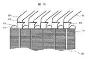
- 9 shows a coil end portion of a stator 20 including a slot liner 310 provided with a bellows portion 311. The state of the stator core 132 after the slot liner is inserted into the slot is shown.
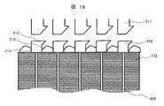
- the state of the stator core 132 when the slot liner expanding jig 511 is inserted into the slot liner 310 is shown. This shows a state of the stator core 132 immediately after the stator coil 60 is inserted into the slot liner 310 whose tip is widened. The state of the stator core 132 after pushing the stator coil 60 into the slot is shown. 9 shows a state of the stator core 132 when the coil stopper jig is removed.
- 1 shows a schematic configuration of a hybrid electric vehicle according to one embodiment.
- FIG. 22 shows a schematic configuration of a hybrid electric vehicle (HEV) on which a rotating electric machine according to an embodiment of the present invention is mounted.
- the rotating electric machine according to one embodiment of the present invention can be applied to a pure electric vehicle (EV) that runs only by the rotating electric machine without an engine in addition to the HEV.
- EV pure electric vehicle
- axial direction refers to a direction along the rotation axis of the rotating electric machine.
- Circumferential direction refers to a direction along the rotation direction of the rotating electric machine.
- Radial direction refers to the radial direction (radial direction) when the rotation axis of the rotating electric machine is the center.
- Inner circumference side indicates the radially inner side (inner diameter side)
- outer circumference side indicates the opposite direction, that is, the radially outer side (outer diameter side).
- the HEV shown in FIG. 22 has an engine ENG and the rotating electric machine 10 as main power sources on the front wheel side.
- the power generated by the engine ENG and the rotary electric machine 10 is transmitted to the front drive wheels FW via the transmission TR.
- the main power source on the rear wheel side is the rotating electric machine 10.
- the rotating electric machine 10 disposed on the rear wheel side and the rear wheel driving wheel RW By mechanically connecting the rotating electric machine 10 disposed on the rear wheel side and the rear wheel driving wheel RW, the power of the rotating electric machine 10 is transmitted to the rear wheel driving wheel RW.
- the rotating electric machine 10, which is a power source on the front wheel side is arranged in a narrow space between the engine ENG and the transmission TR.
- the rotating electric machine 10 starts the engine ENG.
- the rotating electric machine 10 generates a driving force (torque) according to the running state of the vehicle, and also generates electric power to recover kinetic energy as electric energy when the vehicle decelerates.
- the driving operation and the power generation operation of the rotating electric machine 10 are controlled by the power converter INV so that the torque and the rotation speed are optimized according to the driving condition of the vehicle.
- the driving power of the rotating electric machine 10 is supplied from the battery BAT via the power converter INV. Further, electric power generated by rotating electric machine 10 is stored in battery BAT via electric power conversion device INV.
- the rotating electric machine 10 is an embedded permanent magnet synchronous motor.
- the rotating electric machine 10 operates as an electric motor that rotates the rotor when three-phase alternating current is supplied to the stator coil.
- the rotating electric machine 10 When driven by the engine ENG, the rotating electric machine 10 operates as a generator and outputs three-phase AC power. That is, the rotating electric machine 10 has both a function as an electric motor that generates a rotating torque using electric energy and a function as a generator that outputs electric power using mechanical energy. Then, one of the two functions is selectively used according to the traveling state of the vehicle.
- FIG. 1 is a sectional view of a rotating electric machine according to an embodiment of the present invention.
- the rotating electric machine 10 is disposed inside the liquid cooling jacket 130.
- the liquid cooling jacket 130 includes a case of the engine ENG and a case of the transmission TR.
- the rotating electric machine 10 includes a stator 20, a housing 50 that holds the stator 20, and a rotor 11.
- the stator coil is mounted on the stator core 132.
- the coil end portions of the stator coil protrude from the stator core 132 in the rotation axis direction.
- a permanent magnet 18 is embedded in the rotor core 12.
- a shaft 13 serving as a rotation axis is fixed to the center of the rotor core 12.
- An end ring 19 serving as a holding plate for the permanent magnet 18 is provided on the axial end face of the rotor core 12.
- a plurality of thin sheets of electromagnetic steel sheets (silicon steel sheets) are laminated.
- a liquid cooling jacket 130 is fixed to the outer peripheral side of the housing 50.
- a gap between the inner peripheral wall of the liquid cooling jacket 130 and the outer peripheral wall of the housing 50 forms refrigerant passages 153, 154, and 155 for a liquid refrigerant RF such as oil.
- the refrigerant RF accumulated in the refrigerant storage space 150 passes through the refrigerant passage 153, and further passes through the coil passage of the stator 20 via the refrigerant passage 154 and the refrigerant passage 155. It flows toward the ends 61 and 62 and cools the stator 20.
- cooling oil is applied as the refrigerant RF.
- the shaft 13 to which the rotor core 12 is fixed is rotatably supported by bearings 144 and 145 provided on the liquid cooling jacket 130, and is located inside the stator 20 with a predetermined gap from the stator 20. It rotates at a position facing the stator 20. That is, the liquid cooling jacket 130 also functions as a bearing bracket.
- the stator 20 is fixed to the inner peripheral side of the housing 50.
- the rotor 11 is rotatably supported on the inner peripheral side of the stator 20.
- the housing 50 is formed into a cylindrical shape by cutting an iron-based material such as carbon steel, casting cast steel or an aluminum alloy, or pressing, and forms a jacket of the rotating electric machine 10.
- the housing 50 also functions as a frame or a frame.
- the housing 50 is manufactured by drawing a steel plate (such as a high-tensile steel plate) having a thickness of about 2 to 5 mm into a cylindrical shape by drawing.
- the housing 50 has a plurality of flanges (not shown) attached to the liquid cooling jacket 130.
- the plurality of flanges protrude radially outward at the periphery of one end surface of the cylindrical housing 50.
- the flange is formed by cutting off a portion other than the flange at an end of the housing 50 formed at the time of drawing, and is integrated with the housing 50.
- the stator 20 may be directly fixed to the liquid cooling jacket 130 serving as a case without providing the housing 50.
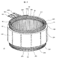
- FIG. 2 is an overall perspective view of the stator 20.
- the stator 20 includes a stator core 132 and a stator coil 60.
- a stator core 132 a plurality of thin sheets of electromagnetic steel sheets (silicon steel sheets) are stacked.
- the stator coil 60 is wound around a plurality of slots 420 provided on the inner periphery of the stator core 132.
- the heat generated by the stator coil 60 is transmitted to the liquid cooling jacket 130 (FIG. 1) via the stator core 132, and is released by the refrigerant RF (FIG. 1) flowing in the liquid cooling jacket 130.
- FIG. 3 is an overall perspective view of the stator core 132.
- the stator core 132 is provided with a plurality of slots 420 parallel to the axial direction of the stator core 132 at equal intervals in the circumferential direction.
- the number of the slots 420 is, for example, 72 in the present embodiment, and the stator coils 60 (FIG. 2) are accommodated in the slots 420.
- Each slot 420 opens on the inner peripheral side of the stator core 132.
- the circumferential width of the opening of the slot 420 is substantially equal to or slightly smaller than the coil mounting portion of each slot 420 where the stator coil 60 is mounted.
- Stator core 132 has teeth 430 between slots 420. Each tooth 430 is integrated with an annular core back 440. That is, the stator core 132 is an integrated core in which the teeth 430 and the core back 440 are integrally formed. The teeth 430 guide the rotating magnetic field generated by the stator coil 60 to the rotor 11. As a result, a rotating torque is generated in the rotor 11.
- the stator core 132 is formed by forming an electromagnetic steel sheet having a thickness of about 0.05 to 1.0 mm by punching, and laminating a plurality of formed annular electromagnetic steel sheets.
- the welded portion 200 is provided in parallel with the axial direction of the stator core 132 at the outer peripheral portion of the cylindrical stator core 132 by TIG (Tungsten Inert Gas) welding, laser welding, or the like. Note that, instead of the welded portion 200, caulking or the like may be applied.
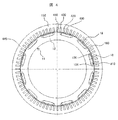
- FIG. 4 shows a cross section of the rotor 11 and the stator core 132 in the rotary electric machine 10 of FIG.
- This cross section is a cross section in a direction perpendicular to the axial direction.
- the illustration of the shaft 13 (FIG. 1) is omitted.
- magnet insertion holes 810 into which the rectangular permanent magnets 18 are inserted are arranged in the rotor core 12 at equal intervals in the circumferential direction.
- the permanent magnet 18 is fixed to each magnet insertion hole 810 by means such as an adhesive, a powder resin, and a mold.
- the circumferential width of the magnet insertion hole 810 is set to be larger than the circumferential width of the permanent magnet 18. Therefore, a magnetic gap 156 is located between both ends in the width direction of the permanent magnet 18 and the rotor core 12.
- An adhesive may be embedded in the magnetic gap 156. Further, by filling the magnetic gap 156 with a molding resin, the resin may be embedded in the magnetic gap 156 and the permanent magnet 18 may be fixed in each magnet insertion hole 810.
- the permanent magnet 18 forms a field pole of the rotor 11.
- one magnetic pole is formed by one permanent magnet 18, but the number of permanent magnets 18 constituting each magnetic pole may be increased.
- the magnetic flux density of each magnetic pole generated by the permanent magnets increases, and the magnet torque can be increased.
- the magnetization direction of the permanent magnet 18 is in the radial direction, and the direction of the magnetization direction is reversed for each field pole.
- the stator-side magnetic pole surface of the permanent magnet 18 for forming a certain magnetic pole is magnetized to the N pole and the rotating shaft side magnetic pole surface is magnetized to the S pole
- the stator of the permanent magnet 18 constituting the adjacent magnetic pole is magnetized.
- the side magnetic pole surface is magnetized so as to have an S pole
- the magnetic pole surface on the rotation axis side has an N pole.
- These permanent magnets 18 are magnetized and arranged in the circumferential direction such that the magnetization direction changes alternately for each magnetic pole.
- twelve permanent magnets 18 are arranged at equal intervals in the circumferential direction, and the rotor 11 has twelve magnetic poles.
- the permanent magnet 18 a neodymium-based, samarium-based sintered magnet, a ferrite magnet, a neodymium-based bonded magnet, or the like can be used.
- the rotor 11 has the auxiliary magnetic pole 160 between the permanent magnets 18.
- the auxiliary magnetic pole 160 acts to reduce the magnetic resistance of the q-axis magnetic flux generated by the stator coil 60. With this auxiliary magnetic pole 160, the reluctance torque can be increased because the magnetic resistance of the q-axis magnetic flux is significantly smaller than the magnetic resistance of the d-axis magnetic flux.
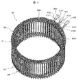
- FIG. 5 is an overall perspective view showing the stator coil 60.
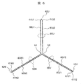
- FIG. 6 is a conceptual diagram showing a connection state of the stator coil 60.
- FIG. 7 is a diagram illustrating the segment conductors 28 constituting the stator coil 60.
- the stator coil 60 is an aggregate of the segment conductors 28 shown in FIG. 7, and is formed by connecting a plurality of segment conductors 28 to each other.
- the stator coil 60 has a two-star configuration in which two star connections are connected in parallel. That is, the stator coil 60 includes a first star connection including a U1-phase coil 60U1, a V1-phase coil 60V1, and a W1-phase coil 60W1, and a second star connection including a U2-phase coil 60U2, a V2-phase coil 60V2, and a W2-phase coil 60W2. It has. The neutral point N1 of the first star connection and the neutral point N2 of the second star connection are separated from each other.
- a rectangular wire having a rectangular cross section is used as the conductor wire constituting the stator coil 60 of the present embodiment.
- the long side of the rectangular cross section extends along the circumferential direction of the stator core 132, and the short side extends along the radial direction of the stator core 132.
- the outer peripheral surface of the rectangular wire is covered with an insulating film.
- Oxygen-free copper or oxygenated copper is used as the conductor material of the rectangular wire. In the case of oxygenated copper, the oxygen content is about 10 ppm or more to about 1000 ppm.
- the cross-sectional shape of the conductor wire constituting the stator coil 60 is not limited to a rectangular shape, but may be a square shape or a round shape. If the shape is rectangular or square, the space factor of the coil in the slot 420 (FIG. 3) can be increased, so that the efficiency of the rotating electric machine can be improved. In the rectangular shape, the side along the radial direction of the stator core 132 may be longer or shorter than the side along the circumferential direction.
- FIG. 7 shows the segment conductor 28 before being mounted on the stator core 132 (upper view) and the segment conductor 28 after being mounted on the stator core 132 (lower view).
- the segment conductor 28 before being attached to the stator core 132 has a substantially U-shape formed of a bent rectangular wire and having a pair of parallel legs 28B and a crown 28C connecting the legs 28B to each other. ing.
- each phase coil a plurality of segment conductors 28 are connected.
- one and the other of the pair of leg portions 28B of the segment conductor 28 are inserted into one and the other of two different slots 420 from one axial side of the stator core 132, respectively.
- leg portions 28B protruding on the other side in the axial direction of the stator core 132 in the two adjacent segment conductors 28 are bent in the direction of the segment conductors 28 to be connected, so that the two facing two segment conductors 28 face each other.
- the ends 28E1 and 28E2 of the two legs 28B1 and 28B2 are welded.
- the set of crowns 28C protruding from one side of the stator core 132 constitutes a coil end 61 on one side of the stator coil 60 shown in FIG.
- a set of end portions 28E protruding to the other side of the stator core 132 constitutes a coil end 62 on the other side of the stator coil 60 shown in FIG.
- the coil end 61 is referred to as “non-welding side coil end 61”
- the coil end 62 is referred to as “welding side coil end 62”.
- a lead wire 41U1 connected to one end of the U1-phase coil 60U1, and a lead wire 41U2 connected to one end of the U2-phase coil 60U2. Is pulled out.
- the lead wire 41U1 and the lead wire 41U2 are both connected to the AC terminal 42U.
- a lead wire 41V1 connected to one end of the V1 phase coil 60V1 and a lead wire 41V2 connected to one end of the V2-phase coil 60V2 are drawn out.
- the lead wire 41V1 and the lead wire 41V2 are both connected to the AC terminal 42V.
- a lead wire 41W1 connected to one end of the W1-phase coil 60W1 and a lead wire 41W2 connected to one end of the W2-phase coil 60W2 are drawn out.
- the lead wire 41W1 and the lead wire 41W2 are both connected to the AC terminal 42W.
- Neutral point connection conductor 40N1 is connected to first star connection neutral point N1 (FIG. 6), and neutral point connection conductor 40N2 is connected to second star connection neutral point N2.
- the stator coil 60 of the present embodiment is wound around the stator core 132 by distributed winding.
- the phase winding is wound around the stator core 132 such that the phase winding is housed in two slots 420 separated from each other across a plurality of slots 420 (FIG. 3).
- the magnetic flux distribution (spatial distribution) of the distributed winding stator coil is closer to a sine wave than that of the concentrated winding stator coil, and the reluctance torque is easily generated. Therefore, the rotating electric machine 10 of the present embodiment improves the controllability of the field weakening control and the control for using the reluctance torque, and is applicable to a wide rotation speed range from a low rotation speed to a high rotation speed. Therefore, according to the rotating electric machine 10 of the present embodiment, motor characteristics suitable for an electric vehicle or the like can be obtained.
- FIG. 8 is a perspective view showing a U-phase coil 60U, which is one phase of the stator coil 60 shown in FIG.
- the U-phase coil 60U includes two phase coils, that is, a U1-phase coil 60U1 and a U2-phase coil 60U2 (see FIG. 6), and one end of each of the U1-phase coil 60U1 and the U2-phase coil 60U2 is commonly used.
- An AC terminal 42U to be connected is provided.
- V-phase coil 60V and W-phase coil 60W have the same configuration as U-phase coil 60U shown in FIG.
- FIG. 9 is a perspective view showing the U1-phase coil 60U1 of the U1-phase coil 60U1 and the U2-phase coil 60U2 (see FIG. 6) constituting the U-phase coil 60U.
- the U1-phase coil 60U1 is wound by distributed winding.
- the lead wire 41U1 and the neutral point connection conductor 40N1 are connected to one end and the other end of the U1-phase coil 60U1, respectively.
- the lead wire 41U1 is connected to the AC terminal 42U.
- Neutral point connection conductor 40N1 is electrically connected to the respective neutral point connection conductors of V1 phase coil 60V1 and W1 phase coil 60W1 (see FIG. 6), which are not shown, and constitutes the neutral point of the first star connection. I do.
- the V1-phase coil 60V1 and the W1-phase coil 60W1 have the same configuration as the U1-phase coil 60U1 shown in FIG. 9, although the winding position on the stator core is different from the U1-phase coil 60U1.
- FIG. 10 is a perspective view showing the U2-phase coil 60U2 of the U1-phase coil 60U1 and the U2-phase coil 60U2 (see FIG. 6) constituting the U-phase coil 60U.
- the U2-phase coil 60U2 is wound by distributed winding.
- the lead wire 41U2 and the neutral point connection conductor 40N2 are connected to one end and the other end of the U2-phase coil 60U2, respectively.
- Lead wire 41U2 is connected to AC terminal 42U.
- Neutral point connection conductor 40N2 is electrically connected to each of the neutral point connection conductors of V2 phase coil 60V2 and W2 phase coil 60W2 (see FIG. 6) which are not shown, and constitutes the neutral point of the second star connection. I do.
- the V2-phase coil 60V2 and the W2-phase coil 60W2 have the same configuration as the U2-phase coil 60U2 shown in FIG. 10, although the winding position on the stator core is different from the U2-phase coil 60U2.
- stator 20 According to the present embodiment, a method of manufacturing the stator 20 according to the present embodiment will be briefly described.
- the legs 28B1 and 28B2 of the segment conductor 28 drawn out of the slot 420 are connected to the segment conductor 28 to be connected. It is bent in the direction.
- the legs 28B1 and 28B2 protruding from the slot 420 are bent to the left and right in the circumferential direction, respectively.
- the end 28E1 of the leg 28B1 and the end 28E2 of the leg 28B2 are arranged so as to be adjacent in the radial direction.
- FIG. 11 shows the vicinity of the plurality of ends 28E1 to 28E4 of the segment conductor 28 after bending and before welding in the welding side coil end 62.
- slot liners 310 are provided on the legs 28B1 to 28B4 inserted into the slots 420.
- the portions adjacent to the openings of the slots 420 in the legs 28B1 to 28B4 protruding from the inside of the slots 420 and the portions located in the slots 420 are formed of a thin body such as insulating paper. It is covered with a slot liner 310 made of an insulator. That is, the slot liner 310 is located inside the slot 420, and a part of the slot liner 310 protrudes out of the slot 420 from the opening of the slot 420. Therefore, in the segment conductor 28 shown in FIG. 7, the straight portion excluding the bent portion is covered with the slot liner 310.
- the ends 28E1 to 28E4 have an insulating coating removed and an exposed conductor surface for electrical connection by welding.
- the slot liner 310 By providing the slot liner 310, the dielectric strength between the segment conductors 28 and between the segment conductors 28 and the inner surface of the slot 420 is improved. Insulating paper 300 for interlayer insulation is provided between the segment conductors adjacent to each other in the radial direction.
- the end 28E1 to the end 28E4 are cut. If the coil ends have the same height, the cutting process may be omitted.
- End 28E1 and end 28E2 are connected by welding.
- the end 28E3 and the end 28E4 are connected by welding. Therefore, a welded portion in which the base material (the conductor portion of the conductor wire) is melted and solidified is formed at the end portion 28E1 and the end portion 28E2. Similar welds are formed at the ends 28E3 and 28E4.
- arc welding such as TIG (Tungsten Inert Gas) welding or plasma welding is applied.
- As the shielding gas argon, helium, a mixed gas of argon and helium, or the like is applied.
- FIG. 12 shows a state of the stator core 132 after the slot liner 310 is inserted into the slot 420 and before the segment conductor 28 is inserted into the slot 420.
- FIG. 12 is a diagram when the stator core 132 is viewed from the near side along the circumferential direction in FIG. 11 (the same applies to FIGS. 13 to 21 described later).
- a coil stopper jig for holding the segment conductor at a predetermined axial position between the projecting portions of the adjacent slot liners 310 from the slot 420. 510 is mounted.
- the coil stopper jig 510 has a rod shape, and is inserted between the projecting portions of the slot liner 310 such that the longitudinal direction is along the circumferential direction (FIG. 11).
- the contact surface with the stator core 132 is flat.
- the contact portion of the coil stopper jig 510 with the slot liner 310 is chamfered to prevent the slot liner 310 from being damaged.
- the exposed surface of the coil stopper jig 510 opposite to the contact surface with the stator core 132 is an arc-shaped curved surface that is convex toward the outside of the coil stopper jig 510.
- the height (h) of the coil stopper jig 510 in the rotation axis direction is lower than the height (H) of the projecting portion of the slot liner 310.
- the coil stopper jig 510 may be mounted using an automatic machine.
- FIG. 13 shows a state of the stator core 132 immediately after the stator coil 60 is inserted into the slot liner 310.
- each segment conductor is inserted into the slot 420 and the slot liner 310.
- each segment conductor is inserted into the slot 420 until a predetermined position corresponding to the height h of the coil stopper jig 510. Is pushed inside. Thereby, the height along the axial direction of the coil end portion can be reduced.
- the pushing amount is limited by the height of the coil stopper jig 510. For this reason, the segment conductor is prevented from being excessively pushed in and the segment conductor and the slot liner 310 are prevented from being damaged.
- the stator coil 60 may be pushed into the slot using an automatic machine.
- FIG. 14 shows a state of the stator core 132 after the stator coil 60 is pushed into the slot.
- the coil stopper jig 510 prevents the stator coil 60 from being excessively pushed in, and the contact portion of the coil stopper jig 510 with the slot liner 310 is chamfered so that the bellows portion is formed. 311 is prevented from being damaged.
- FIG. 15 shows a state of the stator core 132 when the coil stopper jig is removed after the pushing of the stator coil 60 is completed.
- the bellows portions 311 may be provided at both ends of the slot liner 310, that is, at both the welding side and the non-welding side protrusions. Thereby, the coil end height can be reduced, and the electrical insulation distance between the stator coil 60 and the stator core 132 can be ensured.
- FIG. 16 shows a coil end portion of the stator 20 including the slot liner 310 provided with the bellows portion 311 as described above.
- the creeping distance can be increased by the bellows portion 311, the distance between the bent portion 28 ⁇ / b> R adjacent to the stator core 132 in the stator coil 60 and the stator core can be reduced while securing insulation. For this reason, the height of the coil end can be reduced without impairing the insulation of the stator. Further, since the end of the slot liner 310 is formed in a bellows shape, concentration of the stress applied to the end of the slot liner 310 from the bent portion 28R can be avoided, so that the end of the slot liner 310 is prevented from being broken. . Therefore, the reliability of the electrical insulation by the slot liner 310 is improved.
- the pushing amount of the stator coil 60 at the time of forming the bellows is limited by the coil stopper jig, so that in the projecting portion of the slot liner 310, between the bellows portion 311 and the opening of the slot 420, The linear portion 315 is secured. For this reason, the presence or absence of damage to the slot liner 310 can be easily confirmed, and the efficiency of the confirmation operation is improved. Further, since the linear portion 315 is provided on the projecting portion of the slot liner 310, the height of the projecting portion of the slot liner 310 can be made substantially constant, so that the reliability of electrical insulation by the slot liner 310 is improved. I do.
- FIG. 17 shows a state of the stator core 132 of the present modified example after the slot liner 310 is inserted into the slot 420 and before the segment conductor 28 is inserted into the slot 420 (the state of FIG. Correspondence).
- the coil stopper jig 510 is mounted between the projecting portions of the adjacent slot liners 310 from the slots 420, similarly to the above embodiment (FIG. 12).
- the coil stopper jig 510 according to the present modification has a shape different from that of the above embodiment, and this will be described later.
- FIG. 18 shows a state of the stator core 132 when the slot liner expanding jig 511 is inserted into the slot liner 310 in FIG.
- the slot liner expanding jig 511 is pushed into the projecting portion of the slot liner 310 by a predetermined amount, and the circumferential width of the distal end portion 512 of the projecting portion of the slot liner 310 is adjusted to the linear portion 315 of the slot liner 310.
- the circumferential direction so as to be wider than the width in the circumferential direction. This facilitates formation of the bellows portion 311 as described later.
- the tip of the projecting portion of the slot liner 310 in the coil stopper jig 510 is appropriately set according to the shape of the slot liner spreading jig 511.
- slot liner expanding jig 511 may be pushed into the slot liner 310 using an automatic machine.
- FIG. 19 shows a state of the stator core 132 immediately after the stator coil 60 is inserted into the slot liner 310 whose tip is widened.
- each segment conductor is inserted into the slot 420 and the slot liner 310 as in the above embodiment (FIG. 13).
- each segment conductor is pushed into the slot 420 by pressing the entire stator coil 60 from above in the drawing, that is, along the axial direction, similarly to the above-described embodiment (FIG. 13). Also in this modification, the amount of pushing of the stator coil 60 is limited by the height of the coil stopper jig 510, as in the above embodiment.
- FIG. 20 shows the state of the stator core 132 after the stator coil 60 has been pushed into the slot.
- FIG. 21 shows the state of the stator core 132 when the coil stopper jig is removed after the stator coil 60 is completely pushed.
- the bellows portion 311 can ensure a highly reliable electrical insulation distance as in the above-described embodiment (FIG. 15). Furthermore, the insulating property of the stator is improved by the varnish treatment, similarly to the embodiment (FIG. 15).
- the present invention is not limited to the above-described embodiment, and includes various modifications.
- the above-described embodiments have been described in detail for easy understanding of the present invention, and are not necessarily limited to those having all the described configurations. Further, for a part of the configuration of each embodiment, it is possible to add, delete, or replace another configuration.
- V2 phase coil 60W: W-phase coil, 60W1: W1-phase coil, 60W2: W2-phase coil, 61: non-welding side coil end, 62: welding side coil end, 130: liquid cooling jacket, 132: stator core, 144: bearing, 145: bearing, 150: refrigerant storage space, 153: refrigerant passage, 154: refrigerant passage, 155: refrigerant passage, 156: magnetic gap, 160: auxiliary magnetic pole, 200: welded part, 310: slot liner, 311: bellows part 315: Linear portion, 420: Slot, 430: Teeth, 440: Core back, 510: Coil stopper jig, 512: Tip, 810: Magnet insertion hole, BAT: Battery, ENG: Engine, FW: Front wheel side drive Wheel, INV: power conversion device, N1: neutral point, N2: neutral point, TR: transmission, RF: refrigerant, RW: rear wheel side drive wheel
Landscapes
- Engineering & Computer Science (AREA)
- Power Engineering (AREA)
- Manufacturing & Machinery (AREA)
- Manufacture Of Motors, Generators (AREA)
- Windings For Motors And Generators (AREA)
- Insulation, Fastening Of Motor, Generator Windings (AREA)
Abstract
コイルエンドの高さを低減できる回転電機の固定子、回転電機、並びに回転電機の固定子の製造方法を開示する。本回転電機の固定子は、固定子コイル(60)と、固定子コイルが装着されるスロット(420)を有する固定子鉄心(132)と、スロットに挿通される絶縁性のスロットライナー(310)と、を備え、スロットライナーには、固定子コイルを構成する導体線材が挿通され、スロットライナーにおけるスロットからの突出部が蛇腹部(311)を有する。
Description
本発明は、回転電機の固定子、それを用いた回転電機、並びに回転電機の固定子の製造方法に関する。
回転電機においては、固定子コイルに交流電力を供給することで回転磁界を発生させ、この回転磁界により回転子が回転する。また、回転電機においては、回転子に加わる機械エネルギーが電気エネルギーに変換され、固定子コイルから交流電力が出力される。このように、回転電機は、電動機または発電機として作動する。
このような回転電機の固定子において、セグメントコイルの端末を溶接して接続する技術が知られている(例えば特許文献1参照)。また、固定子の絶縁紙に折り曲げ部を設けることにより、ステータコイル部の沿面距離を確保しながらステータコイル部を小型化する技術が知られている(例えば特許文献2参照)。
回転電機を自動車などの狭く限られた空間に取り付けるためには、小型化が要求される。これに対し、固定子におけるコイルエンドの上部と、ミッション部などの取付け部との間の隙間を確保するため、セグメント部における溶接部や非溶接部においてコイルエンド高さを下げることが望ましい。しかし、従来技術による回転電機の固定子では、コイルエンド高さを下げることが難しい。
そこで、本発明は、コイルエンドの高さを低減できる回転電機の固定子、回転電機、並びに回転電機の固定子の製造方法を提供する。
上記課題を解決するために、本発明による回転電機の固定子は、固定子コイルと、固定子コイルが装着されるスロットを有する固定子鉄心と、スロットに挿通される絶縁性のスロットライナーと、を備え、スロットライナーには、固定子コイルを構成する導体線材が挿通され、スロットライナーにおけるスロットからの突出部が蛇腹部を有する。
上記課題を解決するために、本発明による回転電機は、固定子と、固定子に対向する回転子と、を備えるものであって、固定子は上記本発明による回転電機の固定子である。
上記課題を解決するために、本発明による回転電機の固定子の製造方法は、固定子鉄心のスロットに絶縁性のスロットライナーを挿通することと、スロットに挿通されたスロットライナーに、固定子コイルを構成しかつ折り曲げ部を有する導体線材を挿通することと、導体線材の折り曲げ部によって、スロットライナーにおけるスロットからの突出部を押圧することによって、突出部に蛇腹部を形成することを含む。
本発明によれば、固定子の絶縁性を損なうことなくコイルエンドの高さを低減できる。
上記した以外の課題、構成および効果は、以下の実施形態の説明により明らかにされる。
以下、本発明の実施形態について、図面を用いながら説明する。
各図において、参照番号が同一のものは同一の構成要件あるいは類似の機能を備えた構成要件を示している。なお、一図面において説明されない符号の構成要件については、適宜、他の図面において説明される。
まず、本発明の一実施形態である回転電機が搭載される自動車について説明する。
図22は、本発明の一実施形態である回転電機が搭載されるハイブリッド型電気自動車(HEV)の概略構成を示す。なお、本発明の一実施形態である回転電機は、HEVのほか、エンジンを備えなず回転電機のみによって走行する純粋な電気自動車(EV)にも適用できる。
以下の説明において、「軸方向」は回転電機の回転軸に沿った方向を指す。「周方向」は回転電機の回転方向に沿った方向を指す。「径方向」は回転電機の回転軸を中心としたときの動径方向(半径方向)を指す。「内周側」は径方向内側(内径側)を指し、「外周側」はその逆方向、すなわち径方向外側(外径側)を指す。
図22に示すHEVは、前輪側の主動力源として、エンジンENGと回転電機10を有する。エンジンENGと回転電機10の発生する動力は、変速機TRを介して、前輪側駆動輪FWに伝えられる。また、後輪の駆動においては、後輪側の主動力源は回転電機10である。後輪側に配置される回転電機10と後輪側駆動輪RWとが機械的に接続されることにより、回転電機10の動力が後輪側駆動輪RWに伝達される。前輪側の動力源である回転電機10は、エンジンENGと変速機TRの間の狭い空間に配置される。
回転電機10は、エンジンENGを始動する。また、回転電機10は、車両の走行状態に応じて駆動力(トルク)を発生するとともに、車両減速時に、運動エネルギーを電気エネルギーとして回収するため電力を発生する。回転電機10の駆動動作および発電動作は、車両の運転状況に応じて、トルクや回転数が最適になるように電力変換装置INVによって制御される。回転電機10の駆動電力は、電力変換装置INVを介して、バッテリBATから供給される。また、回転電機10が発生する電力は、電力変換装置INVを介してバッテリBATに蓄電される。
回転電機10は、埋込永久磁石同期モータである。回転電機10は、固定子コイルに三相交流電流が供給されることで回転子を回転させる電動機として作動する。また、回転電機10は、エンジンENGによって駆動されると、発電機として作動して三相交流電力を出力する。すなわち、回転電機10は、電気エネルギーによって回転トルクを発生する電動機としての機能と、機械エネルギーによって電力を出力する発電機としての機能の両方を有する。そして、車両の走行状態に応じて、両機能のいずれかが選択的に利用される。
次に、本発明の一実施形態である回転電機について説明する。
図1は、本発明の一実施形態である回転電機の断面図である。
図1に示すように、回転電機10は、液冷ジャケット130の内部に配設されている。液冷ジャケット130は、エンジンENGのケースや変速機TRのケースによって構成される。回転電機10は、固定子20と、固定子20を保持するハウジング50と、回転子11と、を備えている。
固定子20においては、固定子鉄心132に固定子コイルが券装される。固定子コイルのコイルエンド部(後述する、非溶接側コイルエンド61、溶接側コイルエンド62)は、回転軸方向に固定子鉄心132から突出している。回転子11においては、回転子鉄心12内に永久磁石18が埋め込まれる。回転子鉄心12の中心には、回転軸となるシャフト13が固定される。また、回転子鉄心12の軸方向端面には、永久磁石18の押え板となるエンドリング19が設けられる。なお、回転子鉄心12においては、電磁鋼板(珪素鋼板)の薄板が複数枚積層されている。
ハウジング50の外周側には、液冷ジャケット130が固定されている。液冷ジャケット130の内周壁とハウジング50の外周壁との間の空隙によって、油などの液状の冷媒RFの冷媒通路153,154,155が構成される。
なお、本実施形態のように直接液体冷却方式の場合には、冷媒貯蔵空間150に溜まった冷媒RFが、冷媒通路153を通り、さらに冷媒通路154や冷媒通路155を介して固定子20のコイルエンド61,62へ向けて流出し、固定子20を冷却する。ここで、冷媒RFとしては、例えば、冷却用の油が適用される。
回転子鉄心12が固定されるシャフト13は、液冷ジャケット130に設けられる軸受144および軸受145により回転可能に支持され、固定子20内に、固定子20と所定の空隙を介して位置し、固定子20に対向した位置で回転する。すなわち、液冷ジャケット130は、軸受ブラケットとしても機能している。
ハウジング50の内周側には、固定子20が固定されている。固定子20の内周側には、回転子11が回転可能に支持されている。ハウジング50は、炭素鋼など鉄系材料の切削、または鋳鋼やアルミニウム合金の鋳造、またはプレス加工によって、円筒状に成形され、回転電機10の外被を構成する。ハウジング50は、枠体あるいはフレームとしても機能する。
ハウジング50は、厚さ2~5mm程度の鋼板(高張力鋼板など)を絞り加工により円筒形状に成形することにより製造される。ハウジング50には、液冷ジャケット130に取り付けられる複数のフランジ(図示せず)が設けられている。複数のフランジは、円筒状のハウジング50の一端面周縁において、径方向外方に突設されている。なお、フランジは、絞り加工時に形成されるハウジング50の端部において、フランジ以外の部分を切除して形成されるものであり、ハウジング50と一体となっている。なお、ハウジング50を設けずに、固定子20を、ケースとなる液冷ジャケット130に直接固定するようにしてもよい。
図2は、固定子20の全体斜視図である。
図2に示すように、固定子20は、固定子鉄心132と、固定子コイル60とによって構成されている。固定子鉄心132においては、電磁鋼板(珪素鋼板)の薄板が複数枚積層されている。固定子コイル60は、固定子鉄心132の内周部に多数個設けられているスロット420に巻回されている。固定子コイル60が発生する熱は、固定子鉄心132を介して、液冷ジャケット130(図1)に伝わり、液冷ジャケット130内を流通する冷媒RF(図1)により放出される。
図3は、固定子鉄心132の全体斜視図である。
図3に示すように、固定子鉄心132には、固定子鉄心132の軸方向に平行な複数のスロット420が、周方向に等間隔となるように設けられている。スロット420の数は、例えば本実施形態では72個であり、スロット420に固定子コイル60(図2)が収容される。各スロット420は、固定子鉄心132の内周側で開口する。スロット420の開口の周方向の幅は、固定子コイル60が装着される各スロット420のコイル装着部とほぼ同等もしくは、コイル装着部よりも若干小さくなっている。
固定子鉄心132は、スロット420間に、ティース430を有する。それぞれのティース430は、環状のコアバック440と一体となっている。すなわち、固定子鉄心132は、各ティース430とコアバック440とが一体成形された、一体型コアである。ティース430は、固定子コイル60によって発生した回転磁界を回転子11に導く。これにより、回転子11に回転トルクが発生する。
固定子鉄心132は、厚さ0.05~1.0mm程度の電磁鋼板を打ち抜き加工により成形し、成形された円環形状の電磁鋼板を複数枚積層して構成される。溶接部200は、TIG(Tungsten Inert Gas)溶接やレーザー溶接などにより、円筒状の固定子鉄心132の外周部において、固定子鉄心132の軸方向に平行に設けられている。なお、溶接部200に代えて、カシメなどを適用してもよい。
図4は、図1の回転電機10における回転子11および固定子鉄心132の断面を示す。本断面は、軸方向に直角な方向における断面である。なお、本図4では、シャフト13(図1)の図示は省略している。
図4に示すように、回転子鉄心12には、矩形形状の永久磁石18が挿入される磁石挿入孔810が周方向で等間隔に配置されている。各磁石挿入孔810には、永久磁石18が、接着剤、粉体樹脂、モールドなどの手段で固定されている。磁石挿入孔810の周方向の幅は、永久磁石18の周方向の幅よりも大きく設定されている。このため、永久磁石18の幅方向両端と回転子鉄心12との間には磁気的空隙156が位置する。この磁気的空隙156には接着剤を埋め込んでもよい。また、磁気的空隙156内に成形樹脂を充填することによって、磁気的空隙156内に樹脂を埋め込むと共に永久磁石18を各磁石挿入孔810内に固定しても良い。
永久磁石18は、回転子11の界磁極を構成する。本実施形態では、一つの永久磁石18で1つの磁極を形成する構成としているが、各磁極を構成する永久磁石18を複数個に増やしてもよい。永久磁石18を増やすことで、永久磁石が発する各磁極の磁束密度が大きくなり、磁石トルクを増大することができる。
永久磁石18の磁化方向は径方向を向いており、界磁極毎に磁化方向の向きが反転している。すなわち、ある磁極を構成するための永久磁石18の固定子側磁極面がN極、回転軸側の磁極面がS極に磁化されていたとすると、隣の磁極を構成する永久磁石18の固定子側磁極面はS極、回転軸側の磁極面はN極となるように磁化されている。これらの永久磁石18が、周方向に、磁極毎に交互に磁化方向が変わるように磁化されて、配置されている。本実施形態では、各永久磁石18は、周方向に等間隔に12個配置されており、回転子11は12極の磁極を有する。
ここで、永久磁石18としては、ネオジム系、サマリウム系の焼結磁石、フェライト磁石、ネオジム系のボンド磁石などを用いることができる。本実施形態では、回転子11は、永久磁石18間に補助磁極160を有する。補助磁極160は、固定子コイル60が発生するq軸磁束の磁気抵抗を低減するように作用する。この補助磁極160により、q軸磁束の磁気抵抗がd軸磁束の磁気抵抗に比べて大幅に小さくなるため、リラクタンストルクを増大できる。
次に、固定子コイルの構成について、図5~7を用いて説明する。
図5は、固定子コイル60を示す全体斜視図である。図6は、固定子コイル60の接続状態を示す概念図である。図7は、固定子コイル60を構成するセグメント導体28を説明する図である。
図5に示すように、固定子コイル60は、図7に示すセグメント導体28の集合体であり、複数のセグメント導体28が互いに接続されて構成される、図6に示すような三相コイル(U相コイル60U、V相コイル60V、W相コイル60W)である。
本実施形態における固定子コイル60は、図6に示すように、2つのスター結線が並列接続される2スター構成である。すなわち、固定子コイル60は、U1相コイル60U1とV1相コイル60V1とW1相コイル60W1からなる第1スター結線と、U2相コイル60U2とV2相コイル60V2とW2相コイル60W2からなる第2スター結線を備えている。第1スター結線の中性点N1と第2スター結線の中性点N2は互いに分離されている。
本実施形態の固定子コイル60を構成する導体線材として、長方形断面の平角線が適用される。スロット420内において、長方形断面の長辺は、固定子鉄心132の周方向に沿って延び、短辺は固定子鉄心132の径方向に沿って延びる。平角線の外周表面は絶縁被膜で覆われている。平角線の導体材料として、無酸素銅や有酸素銅が用いられる。有酸素銅の場合、酸素含有率は、概略10ppm以上から1000ppm程度である。
なお、固定子コイル60を構成する導体線材の断面形状は、長方形状に限らず、正方形状や丸形状でもよい。なお、長方形状や正方形状にすると、スロット420(図3)におけるコイルの占積率を大きくできるので、回転電機の効率が向上できる。なお、長方形状において、固定子鉄心132の径方向に沿う辺が、周方向に沿う辺よりも、長くてもよいし、短くてもよい。
図7においては、固定子鉄心132に装着する前のセグメント導体28(上図)と、固定子鉄心132に装着した後のセグメント導体28(下図)とが示される。固定子鉄心132に装着する前のセグメント導体28は、折り曲げられた平角線からなり、平行な一対の脚部28Bと、脚部28Bどうしを連結する頭頂部28Cとを有する略U字形状を備えている。
図7(下図)に示すように、各相コイルにおいては、複数のセグメント導体28が接続される。本実施形態においては、セグメント導体28の一対の脚部28Bの一方および他方が、固定子鉄心132の軸方向の一方側から、それぞれ、互いに異なる二つのスロット420の一方および他方に挿入される。さらに、隣接する二つのセグメント導体28において固定子鉄心132の軸方向の他方側に突出する脚部28Bを、接続すべきセグメント導体28の方向に折り曲げて、隣接する二つのセグメント導体28において向かい合う二つの脚部28B1および28B2の端部28E1および28E2が溶接される。
固定子鉄心132の一方の側に突出する頭頂部28Cの集合は、図5に示される固定子コイル60の一方の側のコイルエンド61を構成する。また、固定子鉄心132の他方の側に突出する端部28Eの集合は、図5に示される固定子コイル60の他方の側のコイルエンド62を構成する。なお、以下の説明では、コイルエンド61を「非溶接側コイルエンド61」と記し、コイルエンド62を「溶接側コイルエンド62」と記す。
図5および図6に示すように、非溶接側コイルエンド61の側には、U1相コイル60U1の一端に接続される口出し線41U1と、U2相コイル60U2の一端に接続される口出し線41U2とが引き出される。口出し線41U1と口出し線41U2とは、共に交流端子42Uに接続される。また、V1相コイル60V1の一端に接続される口出し線41V1と、V2相コイル60V2の一端に接続される口出し線41V2とが引き出される。口出し線41V1と口出し線41V2とは、共に交流端子42Vに接続される。また、W1相コイル60W1の一端に接続される口出し線41W1と、W2相コイル60W2の一端に接続される口出し線41W2とが引き出される。口出し線41W1と口出し線41W2とは、共に交流端子42Wに接続される。
さらに、非溶接側コイルエンド61の側には、中性点結線用導体40N1および中性点結線用導体40N2が配置される。中性点結線用導体40N1は、第1スター結線の中性点N1(図6)に接続され、中性点結線用導体40N2は第2スター結線の中性点N2に接続される。
図5に示すように、本実施形態の固定子コイル60は、分布巻によって、固定子鉄心132に巻装されている。分布巻とは、複数のスロット420(図3)を跨いで離間する二つのスロット420に相巻線が収納されるように、相巻線が固定子鉄心132に巻装される。分布巻の固定子コイルによる磁束分布(空間分布)は、集中巻きの固定子コイルに比べて正弦波に近く、リラクタンストルクを発生しやすい。そのため、本実施形態の回転電機10は、弱め界磁制御やリラクタンストルクを用いるための制御の制御性が向上し、低回転速度から高回転速度までの広い回転速度範囲に適用可能である。従って、本実施形態の回転電機10によれば、電気自動車などに好適なモータ特性を得ることができる。
図8は、図5に示した固定子コイル60の一相分であるU相コイル60Uを示す斜視図である。
図8に示すように、U相コイル60Uは、二つの相コイルすなわちU1相コイル60U1およびU2相コイル60U2(図6参照)からなり、U1相コイル60U1およびU2相コイル60U2の各一端が共通に接続される交流端子42Uを備える。
図示されないが、V相コイル60VおよびW相コイル60Wは、固定子鉄心において巻装される位置はU相コイル60Uとは異なるが、図8に示すU相コイル60Uと同様の構成を有する。
図9は、U相コイル60Uを構成するU1相コイル60U1およびU2相コイル60U2(図6参照)の内、U1相コイル60U1を示す斜視図である。
図9に示すように、U1相コイル60U1は分布巻によって巻かれる。口出し線41U1および中性点結線用導体40N1は、それぞれU1相コイル60U1の一端および他端に接続される。口出し線41U1は交流端子42Uに接続される。中性点結線用導体40N1は、図示されないV1相コイル60V1およびW1相コイル60W1(図6参照)の各中性点結線用導体と電気的に接続され、第1スター結線の中性点を構成する。なお、V1相コイル60V1およびW1相コイル60W1は、固定子鉄心において巻装される位置はU1相コイル60U1とは異なるが、図9に示すU1相コイル60U1と同様の構成を有する。
図10は、U相コイル60Uを構成するU1相コイル60U1およびU2相コイル60U2(図6参照)の内、U2相コイル60U2を示す斜視図である。
図10に示すように、U2相コイル60U2は分布巻によって巻かれる。口出し線41U2および中性点結線用導体40N2は、それぞれU2相コイル60U2の一端および他端に接続される。口出し線41U2は交流端子42Uに接続される。中性点結線用導体40N2は、図示されないV2相コイル60V2およびW2相コイル60W2(図6参照)の各中性点結線用導体と電気的に接続され、第2スター結線の中性点を構成する。なお、V2相コイル60V2およびW2相コイル60W2は、固定子鉄心において巻装される位置はU2相コイル60U2とは異なるが、図10に示すU2相コイル60U2と同様の構成を有する。
ここで、本実施形態における固定子20の製造方法について簡単に説明する。
図7に示したように、セグメント導体28を固定子鉄心132のスロット内に挿入された後、スロット420から引き出されたセグメント導体28の脚部28B1,28B2が、接続相手となるセグメント導体28の方向に曲げ加工される。例えば、図7において、スロット420から突出する脚部28B1および28B2は、それぞれ周方向左側および右側に曲げられる。そして、脚部28B1の端部28E1と、脚部28B2の端部28E2は径方向に隣接するように配置される。
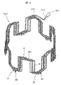
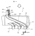
図11は、溶接側コイルエンド62における、曲げ加工後かつ溶接前におけるセグメント導体28の複数の端部28E1~28E4の付近を示す。
図11に示すように、スロット420内には径方向に4列のセグメント導体28が挿通される。スロット420内に挿通される脚部28B1~28B4には、スロットライナー310が配設される。セグメント導体28を構成する導体線材において、スロット420内から突出している脚部28B1~28B4におけるスロット420の開口部に隣接する部分と、スロット420内に位置する部分とが、絶縁紙などの薄体状の絶縁体からなるスロットライナー310によって被覆される。すなわち、スロットライナー310は、スロット420内に位置するとともに、スロットライナー310の一部がスロット420の開口部からスロット420外へ突出する。従って、図7に示すセグメント導体28において、折り曲げ部を除く直線状部分が、スロットライナー310で被覆される。なお、端部28E1ないし端部28E4は、溶接による電気的接続のために、絶縁被膜が除去されていて導体表面が露出している。
スロットライナー310を設けることにより、セグメント導体28の相互間およびセグメント導体28とスロット420の内面との間の絶縁耐圧が向上する。なお、径方向において互いに隣接するセグメント導体間には、層間絶縁用の絶縁紙300が配設される。
端部28E1~28E4の先端の高さを揃えたり、コイルエンド高さを抑えたりするために、端部28E1ないし端部28E4の切断加工を行う。コイルエンドの高さが揃っていれば切断加工は省略しても良い。
端部28E1と端部28E2が溶接により接続される。また、端部28E3と端部28E4が溶接により接続される。このため、端部28E1および端部28E2には、母材(導体線材の導体部)が溶けて固まった溶接部が形成される。また、端部28E3および端部28E4にも、同様の溶接部が形成される。溶接手段としては、TIG(Tungsten Inert Gas)溶接などのアーク溶接や、プラズマ溶接などが適用される。シールドガスとしては、アルゴン、ヘリウム、アルゴンとヘリウムの混合ガスなどが適用される。
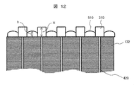
図12は、スロット420にスロットライナー310を挿入した後、かつスロット420内にセグメント導体28を挿入する前における、固定子鉄心132の状態を示す。なお、本図12は、図11中の周方向に沿って手前側から固定子鉄心132を見た場合の図である(後述する図13~21も同様)。
図12に示すように、スロット420にスロットライナー310を挿入したあと、隣接するスロットライナー310におけるスロット420からの突出部の間に、セグメント導体を所定の軸方向位置で保持するためのコイルストッパージグ510が装着される。コイルストッパージグ510は、棒状であり、長手方向が周方向(図11)に沿うように、スロットライナー310の突出部の間に挿入される。コイルストッパージグ510において、固定子鉄心132との接触面は平坦である。コイルストッパージグ510におけるスロットライナー310との接触部は面取り加工され、これによりスロットライナー310の損傷が防止される。
本実施形態では、コイルストッパージグ510における固定子鉄心132との接触面の反対側の露出表面は、コイルストッパージグ510外に向って凸である円弧状曲面である。コイルストッパージグ510の回転軸方向(図11における周方向および径方向に垂直な方向)の高さ(h)は、スロットライナー310の突出部の高さ(H)よりも低い。
なお、コイルストッパージグ510は、自動機械を用いて装着されても良い。
図13は、スロットライナー310に固定子コイル60を挿入した直後における固定子鉄心132の状態を示す。
図13に示すように、各セグメント導体がスロット420内およびスロットライナー310内に挿通される。
図13の状態で、固定子コイル60全体を、図中上方から、すなわち軸方向に沿って押圧することにより、コイルストッパージグ510の高さhに応じた所定位置まで、各セグメント導体がスロット420内に押し込まれる。これにより、コイルエンド部の軸方向に沿った高さを低減できる。ここで、セグメント導体の突き出し部すなわち折り曲げ部28Rが、コイルストッパージグ510に当接する時点で、固定子コイル60の押し込みを終了する。従って、押し込み量は、コイルストッパージグ510の高さによって制限される。このため、セグメント導体が過度に押し込まれ、セグメント導体やスロットライナー310が損傷することが防止される。
なお、固定子コイル60は、自動機械を用いてスロット内に押し込まれても良い。
図14は、固定子コイル60をスロット内へ押し込んだ後の固定子鉄心132の状態を示す。
固定子コイル60を押し込むと、スロットライナー310の突出部の先端部にセグメント導体の折り曲げ部28Rが接し、このような折り曲げ部28Rによってスロットライナー310の突出部が押圧される。これにより、図14に示すように、スロットライナー310の突出部に蛇腹部311が形成される。この蛇腹部311によって、セグメント導体と固定子鉄心132間の電気的絶縁距離が確保されるので、固定子20の絶縁性が向上する。なお、上述のように、コイルストッパージグ510によって固定子コイル60の過度な押し込みが防止されることや、コイルストッパージグ510におけるスロットライナー310との接触部は面取り加工されていることにより、蛇腹部311の損傷が防止される。
なお、図14に示すようなセグメント導体の折り曲げ部28Rが蛇腹状に加工されたスロットライナー310の先端部に接した状態は、蛇腹部311形成以降の固定子製造工程において、また固定子の製造工程完了後においても、保持される。
図15は、固定子コイル60の押し込みが完了した後、コイルストッパージグが取り除かれたときの固定子鉄心132の状態を示す。
蛇腹部311によって、スロットライナー310の突出部が破けにくくなるので、信頼性高く電気的絶縁距離を確保することができる。また、このような状態の固定子にワニス処理を施すと、蛇腹部311の入り口から絶縁ワニスが浸漬するため固定子の絶縁性が向上する。
なお、蛇腹部311は、スロットライナー310の両端部、すなわち溶接側および非溶接側の突出部の両方に設けられても良い。これにより、コイルエンド高さを低減することができるとともに、固定子コイル60と固定子鉄心132との電気的絶縁距離を確保することができる。
図16は、上述のような蛇腹部311が設けられるスロットライナー310を備える固定子20のコイルエンド部を示す。
蛇腹部311によって沿面距離を大きくできるので、絶縁性を確保しながら固定子コイル60において固定子鉄心132に隣接する折り曲げ部28Rと固定子鉄心との間の距離を低減することができる。このため、固定子の絶縁性を損なうことなく、コイルエンドの高さを低減できる。また、スロットライナー310の端部を蛇腹状にすることで、スロットライナー310の端部が折り曲げ部28Rから受ける応力の集中を避けることができるため、スロットライナー310の端部の破けが防止される。従って、スロットライナー310による電気的絶縁の信頼性が向上する。
また、上述のように蛇腹形成時における固定子コイル60の押し込み量がコイルストッパージグによって制限されるため、スロットライナー310の突出部においては、蛇腹部311とスロット420の開口部との間に、直線状部315が確保される。このため、スロットライナー310の損傷の有無を容易に確認することができるので、確認作業の効率が向上する。さらに、スロットライナー310の突出部に直線状部315が設けられることで、スロットライナー310の突出部の高さをほぼ一定にすることができるため、スロットライナー310による電気的絶縁の信頼性が向上する。
次に、上述した実施形態の変形例である回転電機について説明する。なお、主に上記実施形態とは異なる点について説明する。
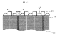
図17は、本変形例について、スロット420にスロットライナー310を挿入した後、かつスロット420内にセグメント導体28を挿入する前における、固定子鉄心132の状態を示す(前述の図12の状態に対応)。
図17に示すように、本変形例においても、上記実施形態(図12)と同様に、隣接するスロットライナー310におけるスロット420からの突出部の間に、コイルストッパージグ510が装着される。なお、本変形例におけるコイルストッパージグ510には、形状において上記実施形態とは異なる点が有るが、この点については後述する。
図18は、図17におけるスロットライナー310にスロットライナー拡げジグ511を挿入するときにおける固定子鉄心132の状態を示す。
図18に示すように、スロットライナー310の突出部内にスロットライナー拡げジグ511を所定量押し込んで、スロットライナー310の突出部の先端部512の周方向の幅を、スロットライナー310の直線状部315の周方向の幅よりも広くなるように、一周方向に向って拡げる。これにより、後述するように、蛇腹部311の形成が容易になる。
ここで、スロットライナー310の突出部の先端部512の拡がり量を所定量確保するとともに、スロットライナー拡げジグ511の押し込み量を制限するために、コイルストッパージグ510におけるスロットライナー310の突出部の先端部512が広がる側の表面形状は、スロットライナー拡げジグ511の形状に応じて適宜設定される。
なお、スロットライナー拡げジグ511は、自動機械を用いてスロットライナー310内に押し込まれても良い。
図19は、先端部を拡げたスロットライナー310に固定子コイル60を挿入した直後における固定子鉄心132の状態を示す。
図19に示すように、各セグメント導体が、上記実施形態(図13)と同様に、スロット420内およびスロットライナー310内に挿通される。
図19の状態で、固定子コイル60全体を、上記実施形態(図13)と同様に、図中上方から、すなわち軸方向に沿って押圧することにより、各セグメント導体をスロット420内に押し込む。本変形例においても、上記実施形態と同様に、固定子コイル60の押し込み量は、コイルストッパージグ510の高さによって制限される。
図20は、固定子コイル60をスロット内へ押し込んだ後の固定子鉄心132の状態を示す。
固定子コイル60を押し込むと、セグメント導体の折り曲げ部28Rによってスロットライナー310の突出部の先端部512の拡がり部が押圧される。これにより、図20に示すように、スロットライナー310の突出部に所望の蛇腹部311が確実に形成される。
図21は、固定子コイル60の押し込みが完了した後、コイルストッパージグが取り除かれたときの固定子鉄心132の状態を示す。
蛇腹部311によって、上記実施形態(図15)と同様に、信頼性高く電気的絶縁距離を確保することができる。さらに、ワニス処理によって、上記実施形態(図15)と同様に、固定子の絶縁性が向上する。
上述の実施形態およびその変形例によれば、コイルエンド部の軸方向寸法すなわちコイルエンド高さを低減しながらも、固定子の絶縁性を確保することができる。このため、回転電機を、絶縁耐力を損なうことなく、小型化することができる。
なお、本発明は前述した実施形態に限定されるものではなく、様々な変形例が含まれる。例えば、前述した実施形態は本発明を分かりやすく説明するために詳細に説明したものであり、必ずしも説明した全ての構成を備えるものに限定されるものではない。また、各実施形態の構成の一部について、他の構成の追加・削除・置き換えをすることが可能である。
10…回転電機、11…回転子、12…回転子鉄心、13…シャフト、18…永久磁石、19…エンドリング、20…固定子、28…セグメント導体、28B,28B1,28B2…脚部、28C…頭頂部、28E…端部、28E1,28E2,28E3,28E4…端部、28R…折り曲げ部、40N1…中性点結線用導体、40N2…中性点結線用導体、41U1…口出し線、41U2…口出し線、41V1…口出し線、41V2…口出し線、41W1…口出し線、41W2…口出し線、42U…交流端子、42V…交流端子、42W…交流端子、50…ハウジング、60…固定子コイル、60U…U相コイル、60U1…U1相コイル、60U2…U2相コイル、60V…V相コイル、60V1…V1相コイル、60V2…V2相コイル、60W…W相コイル、60W1…W1相コイル、60W2…W2相コイル、61…非溶接側コイルエンド、62…溶接側コイルエンド、130…液冷ジャケット、132…固定子鉄心、144…軸受、145…軸受、150…冷媒貯蔵空間、153…冷媒通路、154…冷媒通路、155…冷媒通路、156…磁気的空隙、160…補助磁極、200…溶接部、310…スロットライナー、311…蛇腹部、315…直線状部、420…スロット、430…ティース、440…コアバック、510…コイルストッパージグ、512…先端部、810…磁石挿入孔、BAT…バッテリ、ENG…エンジン、FW…前輪側駆動輪、INV…電力変換装置、N1…中性点、N2…中性点、TR…変速機、RF…冷媒、RW…後輪側駆動輪
Claims (12)
- 回転電機の固定子において、
固定子コイルと、
前記固定子コイルが装着されるスロットを有する固定子鉄心と、
前記スロットに挿通される絶縁性のスロットライナーと、
を備え、
前記スロットライナーには、前記固定子コイルを構成する導体線材が挿通され、
前記スロットライナーにおける前記スロットからの突出部が蛇腹部を有することを特徴とする回転電機の固定子。 - 請求項1に記載の回転電機の固定子において、
前記スロットライナーの前記突出部は、前記蛇腹部と前記固定子鉄心との間に、直線状部を有することを特徴とする回転電機の固定子。 - 請求項1に記載の回転電機の固定子において、
前記スロットライナーは絶縁紙からなることを特徴とする回転電機の固定子。 - 請求項1に記載の回転電機の固定子において、
前記導体線材は、前記固定子コイルのコイルエンド部において、前記固定子鉄心に隣接する折り曲げ部を有し、
前記折り曲げ部が、前記スロットライナーの前記蛇腹部に接することを特徴とする回転電機の固定子。 - 請求項1に記載の回転電機の固定子において、
前記固定子コイルは分布巻によって前記固定子鉄心に巻装されることを特徴とする回転電機の固定子。 - 請求項1に記載の回転電機の固定子において、
前記突出部は、前記スロットライナーの両端に位置することを特徴とする回転電機の固定子。 - 請求項1に記載の回転電機の固定子において、
前記導体線材は絶縁被膜によって被覆されている平角線からなることを特徴とする回転電機の固定子。 - 固定子と、固定子に対向する回転子と、を備える回転電機において、
前記固定子は、
固定子コイルと、
前記固定子コイルが装着されるスロットを有する固定子鉄心と、
前記スロットに挿通される絶縁性のスロットライナーと、
を備え、
前記スロットライナーには、前記固定子コイルを構成する導体線材が挿通され、
前記スロットライナーにおける前記スロットからの突出部が蛇腹部を有することを特徴とする回転電機。 - 請求項8に記載の回転電機において、
前記固定子は液状冷媒によって冷却されることを特徴とする回転電機。 - 回転電機の固定子の製造方法において、
固定子鉄心のスロットに絶縁性のスロットライナーを挿通することと、
前記スロットに挿通された前記スロットライナーに、固定子コイルを構成しかつ折り曲げ部を有する導体線材を挿通することと、
前記導体線材の前記折り曲げ部によって、前記スロットライナーにおける前記スロットからの突出部を押圧することによって、前記突出部に蛇腹部を形成することを含むことを特徴とする回転電機の固定子の製造方法。 - 請求項10に記載の回転電機の固定子の製造方法において、
前記スロットライナーに前記導体線材を挿通する前に、隣接する前記スロットライナーの前記突出部間に、コイルストッパージグを設置することを特徴とする回転電機の固定子の製造方法。 - 請求項10に記載の回転電機の固定子の製造方法において、
前記スロットライナーに前記導体線材を挿通する前に、隣接する前記スロットライナーの前記突出部の先端部を拡げることを特徴とする回転電機の固定子の製造方法。
Priority Applications (2)
| Application Number | Priority Date | Filing Date | Title |
|---|---|---|---|
| JP2020530286A JP7102523B2 (ja) | 2018-07-12 | 2019-07-12 | 回転電機の固定子、回転電機、並びに回転電機の固定子の製造方法 |
| CN201980036505.4A CN112352370B (zh) | 2018-07-12 | 2019-07-12 | 旋转电机的定子、旋转电机以及旋转电机的定子的制造方法 |
Applications Claiming Priority (2)
| Application Number | Priority Date | Filing Date | Title |
|---|---|---|---|
| US16/033,867 | 2018-07-12 | ||
| US16/033,867 US11223253B2 (en) | 2018-07-12 | 2018-07-12 | Stator for rotating electrical machine, rotating electrical machine, and method of producing stator for rotating electrical machine |
Publications (1)
| Publication Number | Publication Date |
|---|---|
| WO2020013331A1 true WO2020013331A1 (ja) | 2020-01-16 |
Family
ID=69138533
Family Applications (1)
| Application Number | Title | Priority Date | Filing Date |
|---|---|---|---|
| PCT/JP2019/027796 Ceased WO2020013331A1 (ja) | 2018-07-12 | 2019-07-12 | 回転電機の固定子、回転電機、並びに回転電機の固定子の製造方法 |
Country Status (4)
| Country | Link |
|---|---|
| US (1) | US11223253B2 (ja) |
| JP (1) | JP7102523B2 (ja) |
| CN (1) | CN112352370B (ja) |
| WO (1) | WO2020013331A1 (ja) |
Families Citing this family (1)
| Publication number | Priority date | Publication date | Assignee | Title |
|---|---|---|---|---|
| JP7562829B2 (ja) | 2020-07-31 | 2024-10-07 | コペンハーゲン アトミクス アーエス | 溶融塩原子炉用のキャンド回転動力式流体機械及び溶融塩原子炉用の流体機械用能動型磁気軸受 |
Citations (7)
| Publication number | Priority date | Publication date | Assignee | Title |
|---|---|---|---|---|
| JPS58170335A (ja) * | 1982-03-31 | 1983-10-06 | Hitachi Ltd | 回転電機のスロツト絶縁物 |
| JP2005012887A (ja) * | 2003-06-18 | 2005-01-13 | Denso Corp | 回転電機の固定子 |
| JP2005110460A (ja) * | 2003-10-01 | 2005-04-21 | Aisin Aw Co Ltd | 回転電機 |
| JP2010154693A (ja) * | 2008-12-25 | 2010-07-08 | Aisin Aw Co Ltd | 回転電機用のコア絶縁部材及び回転電機の絶縁構造 |
| JP2016174441A (ja) * | 2015-03-16 | 2016-09-29 | 日東シンコー株式会社 | スロットライナー |
| WO2017110987A1 (ja) * | 2015-12-25 | 2017-06-29 | アイシン・エィ・ダブリュ株式会社 | ステータおよび回転電機 |
| WO2018011637A1 (en) * | 2016-07-14 | 2018-01-18 | Hitachi Automotive Systems, Ltd. | Stator for rotating electrical machine and rotating electrical machine |
Family Cites Families (9)
| Publication number | Priority date | Publication date | Assignee | Title |
|---|---|---|---|---|
| JPS58170334A (ja) * | 1982-03-31 | 1983-10-06 | Hitachi Ltd | 回転電機のスロツト絶縁物 |
| JP3843644B2 (ja) * | 1999-04-14 | 2006-11-08 | 株式会社デンソー | 回転電機のステータおよびその製造方法 |
| US7788790B2 (en) * | 2006-03-27 | 2010-09-07 | Remy Technologies, L.L.C. | Method for forming a stator core |
| JP4911441B2 (ja) * | 2007-03-05 | 2012-04-04 | 株式会社デンソー | 回転電機の固定子およびそれを用いた回転電機 |
| JP5510709B2 (ja) | 2010-01-22 | 2014-06-04 | 株式会社デンソー | 回転電機の固定子 |
| JP5839851B2 (ja) * | 2011-06-23 | 2016-01-06 | 日立オートモティブシステムズ株式会社 | 回転電機 |
| WO2013061904A1 (ja) * | 2011-10-27 | 2013-05-02 | 住友電気工業株式会社 | セグメントコイル、セグメントコイルの製造方法、セグメントコイル用線材及びステータ |
| JP5860782B2 (ja) * | 2012-08-31 | 2016-02-16 | 日立オートモティブシステムズ株式会社 | 回転電機及びその製造方法 |
| JP2014082935A (ja) * | 2014-02-13 | 2014-05-08 | Hitachi Automotive Systems Ltd | 回転電機の固定子、およびこれを備えた回転電機 |
-
2018
- 2018-07-12 US US16/033,867 patent/US11223253B2/en active Active
-
2019
- 2019-07-12 JP JP2020530286A patent/JP7102523B2/ja active Active
- 2019-07-12 CN CN201980036505.4A patent/CN112352370B/zh active Active
- 2019-07-12 WO PCT/JP2019/027796 patent/WO2020013331A1/ja not_active Ceased
Patent Citations (7)
| Publication number | Priority date | Publication date | Assignee | Title |
|---|---|---|---|---|
| JPS58170335A (ja) * | 1982-03-31 | 1983-10-06 | Hitachi Ltd | 回転電機のスロツト絶縁物 |
| JP2005012887A (ja) * | 2003-06-18 | 2005-01-13 | Denso Corp | 回転電機の固定子 |
| JP2005110460A (ja) * | 2003-10-01 | 2005-04-21 | Aisin Aw Co Ltd | 回転電機 |
| JP2010154693A (ja) * | 2008-12-25 | 2010-07-08 | Aisin Aw Co Ltd | 回転電機用のコア絶縁部材及び回転電機の絶縁構造 |
| JP2016174441A (ja) * | 2015-03-16 | 2016-09-29 | 日東シンコー株式会社 | スロットライナー |
| WO2017110987A1 (ja) * | 2015-12-25 | 2017-06-29 | アイシン・エィ・ダブリュ株式会社 | ステータおよび回転電機 |
| WO2018011637A1 (en) * | 2016-07-14 | 2018-01-18 | Hitachi Automotive Systems, Ltd. | Stator for rotating electrical machine and rotating electrical machine |
Also Published As
| Publication number | Publication date |
|---|---|
| CN112352370B (zh) | 2023-09-05 |
| US11223253B2 (en) | 2022-01-11 |
| US20200021158A1 (en) | 2020-01-16 |
| JP7102523B2 (ja) | 2022-07-19 |
| CN112352370A (zh) | 2021-02-09 |
| JPWO2020013331A1 (ja) | 2021-04-30 |
Similar Documents
| Publication | Publication Date | Title |
|---|---|---|
| JP6563595B2 (ja) | 回転電機、及び回転電機の固定子 | |
| JP6402257B2 (ja) | 固定子コイル、これを備えた固定子、およびこれを備えた回転電機 | |
| JP6793257B2 (ja) | 回転電機の固定子、及び回転電機 | |
| JP7100130B2 (ja) | 回転電機の固定子、回転電機、並びに回転電機の固定子の製造方法 | |
| US10411526B2 (en) | Stator for rotating electrical machine and rotating electrical machine | |
| JP6499064B2 (ja) | 回転電機用固定子の製造方法 | |
| JP6719671B2 (ja) | 回転電機の固定子、及び回転電機 | |
| US10505426B2 (en) | Dynamo-electric machine | |
| WO2019208032A1 (ja) | 固定子、及び回転電機 | |
| JP7102523B2 (ja) | 回転電機の固定子、回転電機、並びに回転電機の固定子の製造方法 |
Legal Events
| Date | Code | Title | Description |
|---|---|---|---|
| 121 | Ep: the epo has been informed by wipo that ep was designated in this application |
Ref document number: 19833044 Country of ref document: EP Kind code of ref document: A1 |
|
| ENP | Entry into the national phase |
Ref document number: 2020530286 Country of ref document: JP Kind code of ref document: A |
|
| NENP | Non-entry into the national phase |
Ref country code: DE |
|
| 122 | Ep: pct application non-entry in european phase |
Ref document number: 19833044 Country of ref document: EP Kind code of ref document: A1 |