WO2020012901A1 - 内燃機関のブローバイガス還流装置 - Google Patents
内燃機関のブローバイガス還流装置 Download PDFInfo
- Publication number
- WO2020012901A1 WO2020012901A1 PCT/JP2019/024311 JP2019024311W WO2020012901A1 WO 2020012901 A1 WO2020012901 A1 WO 2020012901A1 JP 2019024311 W JP2019024311 W JP 2019024311W WO 2020012901 A1 WO2020012901 A1 WO 2020012901A1
- Authority
- WO
- WIPO (PCT)
- Prior art keywords
- blow
- gas
- oil
- adsorption
- passage
- Prior art date
- Legal status (The legal status is an assumption and is not a legal conclusion. Google has not performed a legal analysis and makes no representation as to the accuracy of the status listed.)
- Ceased
Links
Images

Classifications
-
- F—MECHANICAL ENGINEERING; LIGHTING; HEATING; WEAPONS; BLASTING
- F01—MACHINES OR ENGINES IN GENERAL; ENGINE PLANTS IN GENERAL; STEAM ENGINES
- F01M—LUBRICATING OF MACHINES OR ENGINES IN GENERAL; LUBRICATING INTERNAL COMBUSTION ENGINES; CRANKCASE VENTILATING
- F01M13/00—Crankcase ventilating or breathing
- F01M13/04—Crankcase ventilating or breathing having means for purifying air before leaving crankcase, e.g. removing oil
-
- B—PERFORMING OPERATIONS; TRANSPORTING
- B01—PHYSICAL OR CHEMICAL PROCESSES OR APPARATUS IN GENERAL
- B01D—SEPARATION
- B01D46/00—Filters or filtering processes specially modified for separating dispersed particles from gases or vapours
- B01D46/0027—Filters or filtering processes specially modified for separating dispersed particles from gases or vapours with additional separating or treating functions
- B01D46/003—Filters or filtering processes specially modified for separating dispersed particles from gases or vapours with additional separating or treating functions including coalescing means for the separation of liquid
- B01D46/0031—Filters or filtering processes specially modified for separating dispersed particles from gases or vapours with additional separating or treating functions including coalescing means for the separation of liquid with collecting, draining means
-
- B—PERFORMING OPERATIONS; TRANSPORTING
- B01—PHYSICAL OR CHEMICAL PROCESSES OR APPARATUS IN GENERAL
- B01D—SEPARATION
- B01D46/00—Filters or filtering processes specially modified for separating dispersed particles from gases or vapours
- B01D46/24—Particle separators, e.g. dust precipitators, using rigid hollow filter bodies
-
- B—PERFORMING OPERATIONS; TRANSPORTING
- B01—PHYSICAL OR CHEMICAL PROCESSES OR APPARATUS IN GENERAL
- B01D—SEPARATION
- B01D53/00—Separation of gases or vapours; Recovering vapours of volatile solvents from gases; Chemical or biological purification of waste gases, e.g. engine exhaust gases, smoke, fumes, flue gases, aerosols
- B01D53/02—Separation of gases or vapours; Recovering vapours of volatile solvents from gases; Chemical or biological purification of waste gases, e.g. engine exhaust gases, smoke, fumes, flue gases, aerosols by adsorption, e.g. preparative gas chromatography
- B01D53/04—Separation of gases or vapours; Recovering vapours of volatile solvents from gases; Chemical or biological purification of waste gases, e.g. engine exhaust gases, smoke, fumes, flue gases, aerosols by adsorption, e.g. preparative gas chromatography with stationary adsorbents
- B01D53/0407—Constructional details of adsorbing systems
-
- F—MECHANICAL ENGINEERING; LIGHTING; HEATING; WEAPONS; BLASTING
- F02—COMBUSTION ENGINES; HOT-GAS OR COMBUSTION-PRODUCT ENGINE PLANTS
- F02M—SUPPLYING COMBUSTION ENGINES IN GENERAL WITH COMBUSTIBLE MIXTURES OR CONSTITUENTS THEREOF
- F02M35/00—Combustion-air cleaners, air intakes, intake silencers, or induction systems specially adapted for, or arranged on, internal-combustion engines
- F02M35/10—Air intakes; Induction systems
- F02M35/10209—Fluid connections to the air intake system; their arrangement of pipes, valves or the like
- F02M35/10222—Exhaust gas recirculation [EGR]; Positive crankcase ventilation [PCV]; Additional air admission, lubricant or fuel vapour admission
-
- B—PERFORMING OPERATIONS; TRANSPORTING
- B01—PHYSICAL OR CHEMICAL PROCESSES OR APPARATUS IN GENERAL
- B01D—SEPARATION
- B01D2257/00—Components to be removed
- B01D2257/70—Organic compounds not provided for in groups B01D2257/00 - B01D2257/602
-
- B—PERFORMING OPERATIONS; TRANSPORTING
- B01—PHYSICAL OR CHEMICAL PROCESSES OR APPARATUS IN GENERAL
- B01D—SEPARATION
- B01D2259/00—Type of treatment
- B01D2259/45—Gas separation or purification devices adapted for specific applications
- B01D2259/4566—Gas separation or purification devices adapted for specific applications for use in transportation means
-
- F—MECHANICAL ENGINEERING; LIGHTING; HEATING; WEAPONS; BLASTING
- F01—MACHINES OR ENGINES IN GENERAL; ENGINE PLANTS IN GENERAL; STEAM ENGINES
- F01M—LUBRICATING OF MACHINES OR ENGINES IN GENERAL; LUBRICATING INTERNAL COMBUSTION ENGINES; CRANKCASE VENTILATING
- F01M13/00—Crankcase ventilating or breathing
- F01M13/02—Crankcase ventilating or breathing by means of additional source of positive or negative pressure
- F01M13/021—Crankcase ventilating or breathing by means of additional source of positive or negative pressure of negative pressure
- F01M2013/027—Crankcase ventilating or breathing by means of additional source of positive or negative pressure of negative pressure with a turbo charger or compressor
-
- F—MECHANICAL ENGINEERING; LIGHTING; HEATING; WEAPONS; BLASTING
- F01—MACHINES OR ENGINES IN GENERAL; ENGINE PLANTS IN GENERAL; STEAM ENGINES
- F01M—LUBRICATING OF MACHINES OR ENGINES IN GENERAL; LUBRICATING INTERNAL COMBUSTION ENGINES; CRANKCASE VENTILATING
- F01M13/00—Crankcase ventilating or breathing
- F01M13/04—Crankcase ventilating or breathing having means for purifying air before leaving crankcase, e.g. removing oil
- F01M2013/0438—Crankcase ventilating or breathing having means for purifying air before leaving crankcase, e.g. removing oil with a filter
-
- F—MECHANICAL ENGINEERING; LIGHTING; HEATING; WEAPONS; BLASTING
- F02—COMBUSTION ENGINES; HOT-GAS OR COMBUSTION-PRODUCT ENGINE PLANTS
- F02B—INTERNAL-COMBUSTION PISTON ENGINES; COMBUSTION ENGINES IN GENERAL
- F02B37/00—Engines characterised by provision of pumps driven at least for part of the time by exhaust
Definitions
- the present disclosure relates to a blow-by gas recirculation device for an internal combustion engine, and particularly to a blow-by gas recirculation device for a turbocharged internal combustion engine.
- a blow-by gas recirculation device for recirculating blow-by gas leaked into a crankcase from a gap between a piston and a cylinder into an intake passage is known. Further, a turbocharged internal combustion engine provided with a compressor of a turbocharger in an intake passage is also known.
- a blow-by gas passage that recirculates the blow-by gas may be connected to a position upstream of the compressor in the intake passage.
- the oil mixed into the blow-by gas is also returned to the intake passage, and the oil may cause a caulking abnormality in the compressor.
- oil having a large particle diameter is mainly separated by an oil separator provided in a blow-by gas passage, but oil having a small particle diameter is not mainly separated by an oil separator. Pass through.
- the oil having a small particle diameter is easily thermally denatured by the heat of the compressor as compared with the oil having a large particle diameter.
- the present disclosure has been devised in view of such circumstances, and an object thereof is to provide a blow-by gas recirculation device for an internal combustion engine that can suppress coking abnormality of a compressor caused by oil contained in blow-by gas that has passed through an oil separator. It is in.
- a blow-by gas recirculation device for an internal combustion engine, the internal combustion engine including: an intake passage; and a turbocharger compressor provided in the intake passage.
- the apparatus includes a blow-by gas passage connected to the intake passage at a position on the upstream side of the compressor, an oil separator provided in the blow-by gas passage, for separating oil from the blow-by gas, the oil separator, and the oil separator. It is provided in at least one of the intake passage and the blow-by gas passage located between the compressor and the compressor, adsorbs oil contained in the blow-by gas that has passed through the oil separator, and expands and desorbs the oil particle size. Characterized in that the suction and desorption member is configured to Igasu recirculation device is provided.
- the intake passage has a connection portion to which the blow-by gas passage is connected, and the adsorption / desorption member is provided on an inner peripheral surface of the connection portion opposite to the blow-by gas passage side.
- a bent portion is formed in at least one of the intake passage and the blow-by gas passage, and the adsorption / desorption member is provided on an inner peripheral surface of the bent portion on an out corner side.
- the adsorption / desorption member is formed of a nonwoven fabric.
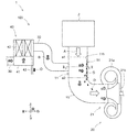
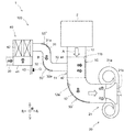
- FIG. 1 is a schematic diagram showing the configuration of the embodiment.
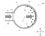
- FIG. 2 is a sectional view taken along line II-II of FIG.
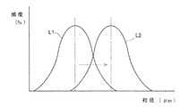
- FIG. 3 is a graph showing the operation and effect of the embodiment.
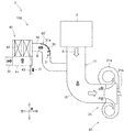
- FIG. 4 is a schematic diagram showing a first modification.
- FIG. 5 is a schematic diagram showing a second modification.
- FIG. 6 is a schematic diagram showing a third modification.
- FIG. 1 is a schematic diagram illustrating a configuration of an embodiment of the present disclosure.
- FIG. 2 is a sectional view taken along line II-II of FIG.
- the outline arrow A indicates the flow of intake air of the internal combustion engine 1
- the shaded arrow B indicates the flow of blow-by gas of the internal combustion engine 1. Note that the directions of up, down, left, and right shown in these figures are merely defined for convenience of explanation.
- the internal combustion engine 1 is a multi-cylinder compression ignition type internal combustion engine mounted on a vehicle (not shown), that is, a diesel engine.
- vehicle is a large vehicle such as a truck.
- the vehicle may be a small vehicle such as a passenger car, or the internal combustion engine 1 may be a spark ignition type internal combustion engine, that is, a gasoline engine. Is also good.
- the internal combustion engine 1 includes an intake pipe 10 as an intake passage, and a compressor 21 of a turbocharger 20 provided in the intake pipe 10.
- the internal combustion engine 1 includes an engine body (not shown) and exhaust system components such as an exhaust pipe (not shown), but the description is omitted here.
- the air cleaner 2 for removing dust and the like contained in the intake air A is connected to the upstream end of the intake pipe 10.
- the downstream end of the intake pipe 10 is connected to a cylinder head of an engine body via an intake manifold (not shown).
- the intake pipe 10 of the present embodiment has a connection portion 11 to which a blow-by gas pipe 30 described later is connected.
- the connection part 11 of this embodiment is a part between two-dot chain lines a1 and a2 shown in FIG.
- a gas inlet 11 a for introducing the blow-by gas B from the blow-by gas pipe 30 is formed at a central portion in the axial direction of the connection portion 11.
- the turbocharger 20 includes a turbine (not shown) that is rotationally driven by exhaust gas flowing through an exhaust pipe, and a compressor 21 that is rotationally driven by the rotational force of the turbine.
- the compressor 21 includes a compressor housing 21a and a compressor wheel 21b rotatably provided in the compressor housing 21a.
- the blow-by gas recirculation device 100 of the internal combustion engine 1 includes a blow-by gas pipe 30 connected to the intake pipe 10 at a position upstream of the compressor 21.
- the blow-by gas recirculation device 100 includes an oil separator 40 provided in the blow-by gas pipe 30 for separating oil from the blow-by gas B.
- the blow-by gas recirculation device 100 includes an adsorption / desorption member 50 provided between at least one of the intake pipe 10 and the blow-by gas pipe 30 located between the oil separator 40 and the compressor 21.
- the adsorption / desorption member 50 provided in the intake pipe 10 will be described.
- the blow-by gas passage includes a gas passage (not shown) on the engine body side extending from the inside of the crankcase through the cylinder block and the cylinder head into the head cover, and a blow-by gas pipe connected to a downstream end of the gas passage. 30.
- blow-by gas pipe 30 for example, a resin hose member is used.
- the downstream end of the blow-by gas pipe 30 is connected to a gas inlet 11 a formed in the connection part 11.
- the oil separator 40 is provided in the middle of the blow-by gas pipe 30.
- the oil separator 40 includes a casing 41 and a cylindrical filter element 42 housed in the casing 41.
- the oil separator 40 includes a return pipe 43 for returning separated oil indicated by a black arrow O into the crankcase.
- the oil separator 40 is configured to introduce the blow-by gas B into the casing 41 from the upstream blow-by gas pipe 30 and to separate the oil by filtering the blow-by gas B by the filter element 42. Is done.
- the oil separator 40 is configured to discharge the blow-by gas B after oil separation to the downstream blow-by gas pipe 30 and discharge the separated oil O to the return pipe 43.
- the filter element 42 of the present embodiment mainly separates oil having a large particle diameter (for example, about 1 ⁇ m), but mainly removes mist-like oil having a small particle diameter (for example, about 0.5 ⁇ m) together with the blow-by gas B. Let it pass.
- the adsorption / desorption member 50 is configured to adsorb the oil contained in the blow-by gas B that has passed through the oil separator 40, and to desorb the oil by expanding the particle diameter of the oil.
- the adsorption / desorption member 50 of the present embodiment is provided on the inner peripheral surface 11b of the connection portion 11 on the side opposite to the blow-by gas pipe 30 side. As will be described in detail later, the adsorption / desorption member 50 is provided on the inner peripheral surface 11b at a position where the blow-by gas B introduced into the connection portion 11 from the blow-by gas pipe 30 collides.
- the adsorption / desorption member 50 is formed of a nonwoven fabric. As shown in FIG. 2, the adsorption / desorption member 50 is formed in a semi-cylindrical shape, and is laid on the inner peripheral surface 11b on the side opposite to the gas inlet 11a with respect to the tube axis C over a half circumference. Further, the adsorption / desorption member 50 is provided so as to extend upstream and downstream from the position of the gas inlet 11a in the tube axis direction of the connection portion 11.
- the blow-by gas B in the crankcase is returned to the intake pipe 10 through a gas passage (not shown) on the engine body side and the blow-by gas pipe 30.
- coking abnormality may occur in the compressor 21 due to oil mixed in the blow-by gas B returned to the intake pipe 10.
- the oil is still at a low temperature of about room temperature on the upstream side of the compressor 21 and is a relatively low-viscosity liquid.
- the oil contained in the intake air A is also heated to a high temperature (about 160 to 170 ° C.) and has a relatively high viscosity. Denature to liquid.
- the high-viscosity oil adheres to the sliding portion between the compressor housing 21a and the compressor wheel 21b, and increases the sliding resistance. Further, the high-viscosity oil adheres to the compressor outlet passage on the downstream side of the compressor wheel 21b and partially blocks the compressor outlet passage.
- caulking abnormality The adhesion of the high-viscosity oil to various places as described above is called caulking, and the abnormality of the compressor 21 caused by the caulking is called the caulking abnormality.
- the caulking abnormality occurs, the original performance of the compressor 21 may not be able to be exhibited.
- oil O having a large particle diameter for example, about 1 ⁇ m
- mist-like oil (not shown) mainly having a small particle size (for example, about 0.5 ⁇ m) passes through the oil separator 40 without being completely separated.
- the oil contained in the blow-by gas B has a property of being easily thermally denatured by the heat of the compressor 21 because the smaller the particle size, the larger the surface area ratio to the mass. Therefore, rather than oil having a large particle diameter separated by the oil separator 40, oil having a small particle diameter that has passed without being completely separated by the oil separator 40 is more likely to cause coking abnormality.
- the adsorption / desorption member 50 adsorbs the oil contained in the blow-by gas B that has passed through the oil separator 40, and expands the oil particle size to release the oil. Let go.
- the adsorption / desorption member 50 adsorbs oil having a small particle diameter that has passed without being completely separated by the oil separator 40, and increases the particle diameter by collecting the oil. Then, the oil D having an increased particle diameter oozes out, for example, exceeding the adsorption allowable amount of the adsorption / desorption member 50, and falls by its own weight, or is scattered downstream by the intake air A and the blow-by gas B. Thereby, the oil D having a large particle diameter can be desorbed from the adsorption / desorption member 50.
- FIG. 3 is a graph schematically showing the particle size distribution of the oil contained in the blow-by gas B.
- the vertical axis indicates the frequency (%) in which the amount of oil particles in the intake pipe 10 immediately upstream of the compressor 21 is represented as an existence ratio, and the horizontal axis indicates the particle size ( ⁇ m) of the oil.
- a curve L1 shows an oil particle size distribution curve when the adsorption / desorption member 50 is not provided, and a curve L2 shows an oil particle size distribution curve in the present embodiment in which the adsorption / desorption member 50 is provided. .
- the small particle The oil with a large particle diameter is decreasing, and the oil with a large particle diameter is increasing. Then, the oil whose particle diameter has been expanded in this way has a smaller surface area ratio to the mass than before the oil is expanded, and therefore is less likely to be thermally denatured by the heat of the compressor 21.
- blow-by gas recirculation device 100 it is possible to suppress the occurrence of the coking abnormality of the compressor 21 caused by the oil contained in the blow-by gas B that has passed through the oil separator 40.
- the adsorption / desorption member 50 of the present embodiment is provided on the inner peripheral surface 11b of the connection portion 11 of the intake pipe 10 on the side opposite to the blow-by gas pipe 30 side.
- the adsorption / desorption member 50 is provided on the inner peripheral surface of the straight portion of the intake pipe 10 or the blow-by gas pipe 30.
- the oil contained in the blow-by gas B flows in the pipe axis direction together with the blow-by gas B, and simply passes through the adsorption / desorption member 50. Therefore, in this comparative example, the adsorption / desorption member 50 cannot sufficiently adsorb the oil.
- the flow direction of the blow-by gas B introduced from the blow-by gas pipe 30 into the connection portion 11 is bent downstream of the intake pipe 10. Therefore, the oil contained in the blow-by gas B collides with the adsorption / desorption member 50 on the out-corner side without being completely bent by the inertial force. Therefore, the adsorption / desorption member 50 can efficiently and surely adsorb the oil contained in the blow-by gas B.
- the adsorption / desorption member 50 is formed of a nonwoven fabric. Therefore, the adsorbing / desorbing member 50 can be easily provided simply by attaching the nonwoven fabric to the inner peripheral surface 11b of the connecting portion 11.
- a bent portion 12 is formed in the intake pipe 10, and the adsorption / desorption member 50 ′ may be provided on the inner peripheral surface 12 a on the out corner side of the bent portion 12 of the intake pipe 10.
- the bent portion 12 of the intake pipe 10 is a portion that is bent 90 ° rightward from the position of the downstream end of the connection portion 11. Note that the bent portion 12 may be bent at an angle other than 90 °.
- the adsorption / desorption member 50 ′ of the first modified example is laid on the inner peripheral surface 12 a on the out corner side of the bent portion 12 of the intake pipe 10 over a half circumference.
- the adsorption / desorption member 50 ' is provided over the entire length of the bent portion 12 in the tube axis direction.
- the flow direction of the blow-by gas B is bent at the bent portion 12 of the intake pipe 10, so that the oil contained in the blow-by gas B collides with the adsorption / desorption member 50 'without being completely turned by the inertial force. I do.
- the adsorption / desorption member 50 ' can efficiently and reliably adsorb the oil contained in the blow-by gas B, similarly to the above-described basic embodiment.
- the adsorption / desorption member 50 ′′ may be provided in the blow-by gas pipe 30. Further, a bent portion 31 is formed in the blow-by gas pipe 30, and the adsorption / desorption member 50 ′′ is It may be provided on the inner peripheral surface 31a on the out corner side in the bent portion 31 of the blow-by gas pipe 30.
- the bent portion 31 of the blow-by gas pipe 30 is a portion extending rightward from the outlet side of the oil separator 40 and bent downward at an angle of 90 °. Note that the bent portion 31 may be bent at an angle other than 90 °.
- the adsorption / desorption member 50 ′′ of the second modified example is laid on the inner peripheral surface 31a on the out corner side of the bent portion 31 of the blow-by gas pipe 30 over a half circumference. "" Is provided over the entire length of the bent portion 31 in the tube axis direction.
- the oil contained in the blow-by gas B that has passed through the oil separator 40 can be adsorbed by the adsorption / desorption member 50 ′′ in the blow-by gas pipe 30, and the oil particle diameter can be enlarged and desorbed. .
- the adsorption / desorption member 50 ′′ on the inner peripheral surface 31a on the out corner side of the bent portion 31 of the blow-by gas pipe 30, the oil contained in the blow-by gas B collides with the adsorption / desorption member 50 ′′, Adsorption can be performed efficiently and reliably.
- a plurality of adsorption / desorption members 50, 50 ′, 50 ′′ may be provided by combining the above-described basic embodiment, the first and second modifications.
- the adsorption / desorption members 50, 50 ', and 50 may be provided at any positions as long as they are located between the oil separator 40 and the compressor 21.
- a bent portion 32 may be provided in the blow-by gas pipe 30 downstream of the bent portion 31 shown in the example, and an adsorption / desorption member 50 ′′ may be provided on the inner peripheral surface 32 a of the bent portion 32 on the outer corner side.
- the adsorption / desorption members 50, 50 ', 50 are not limited to non-woven fabrics, and may be formed of any material.
- the adsorption / desorption members 50, 50', 50" may be formed of a porous material.
- a material such as a formed filter or a sponge, a net, a woven fabric, a felt, or the like may be used.
- the adsorption / desorption member may be laid all around the inner peripheral surface of the above-described bent portion 12, 31, 32. Further, the adsorption / desorption member may be provided on the inner peripheral surface of the straight portion of the intake pipe 10 or the blow-by gas pipe 30 if a desired effect is obtained.
Landscapes
- Engineering & Computer Science (AREA)
- Chemical & Material Sciences (AREA)
- Mechanical Engineering (AREA)
- General Engineering & Computer Science (AREA)
- Chemical Kinetics & Catalysis (AREA)
- Combustion & Propulsion (AREA)
- Analytical Chemistry (AREA)
- General Chemical & Material Sciences (AREA)
- Oil, Petroleum & Natural Gas (AREA)
- Lubrication Details And Ventilation Of Internal Combustion Engines (AREA)
Abstract
ブローバイガス還流装置100は、吸気通路10に接続されたブローバイガス通路30と、ブローバイガス通路30に設けられたオイルセパレータ40と、オイルセパレータ40とターボチャージャ20のコンプレッサ21との間に位置する吸気通路10及びブローバイガス通路30の少なくとも何れか一方に設けられ、ブローバイガスBに含まれるオイルを吸着し、オイルの粒径を拡大させて脱離するように構成された吸着脱離部材50と、を備える。
Description
本開示は、内燃機関のブローバイガス還流装置、特に、ターボ過給式内燃機関のブローバイガス還流装置に関する。
ピストンとシリンダの隙間からクランクケース内に漏出したブローバイガスを吸気通路に環流させるブローバイガス環流装置が公知である。また、ターボチャージャのコンプレッサを吸気通路に備えたターボ過給式内燃機関も公知である。
吸気通路におけるコンプレッサの上流側の位置に、ブローバイガスを環流させるブローバイガス通路が接続されることがある。この場合、ブローバイガスに混入したオイルも吸気通路に環流され、このオイルに起因してコンプレッサにコーキング異常が発生することがある。
また、ブローバイガスに混入したオイルのうち、主に粒径の大きいオイルは、ブローバイガス通路に設けられたオイルセパレータで分離されるが、主に粒径の小さいオイルは、オイルセパレータで分離されずに通過してしまう。そして、粒径が小さいオイルは、粒径の大きいオイルに比べてコンプレッサの熱で容易に熱変性するので、コーキング異常を発生させ易い。
そこで、本開示は、かかる事情に鑑みて創案され、その目的は、オイルセパレータを通過したブローバイガスに含まれるオイルに起因するコンプレッサのコーキング異常を抑制できる内燃機関のブローバイガス還流装置を提供することにある。
本開示の一の態様によれば、内燃機関のブローバイガス還流装置であって、前記内燃機関は、吸気通路と、前記吸気通路に設けられたターボチャージャのコンプレッサと、を備え、前記ブローバイガス還流装置は、前記コンプレッサの上流側の位置において前記吸気通路に接続されたブローバイガス通路と、前記ブローバイガス通路に設けられ、前記ブローバイガスからオイルを分離するためのオイルセパレータと、前記オイルセパレータと前記コンプレッサとの間に位置する前記吸気通路及び前記ブローバイガス通路の少なくとも何れか一方に設けられ、前記オイルセパレータを通過したブローバイガスに含まれるオイルを吸着し、オイルの粒径を拡大させて脱離するように構成された吸着脱離部材と、を備えたことを特徴とするブローバイガス還流装置が提供される。
好ましくは、前記吸気通路は、前記ブローバイガス通路が接続される接続部を有し、前記吸着脱離部材は、前記接続部における前記ブローバイガス通路側と反対側の内周面に設けられる。
好ましくは、前記吸気通路及び前記ブローバイガス通路の少なくとも一方には、曲がり部が形成され、前記吸着脱離部材は、前記曲がり部におけるアウトコーナー側の内周面に設けられる。
好ましくは、前記吸着脱離部材は、不織布により形成される。
本開示によれば、オイルセパレータを通過したブローバイガスに含まれるオイルに起因するコンプレッサのコーキング異常を抑制することができる。
以下、添付図面を参照して本開示の実施形態を説明する。なお、本開示は以下の実施形態に限定されない点に留意されたい。
図1は、本開示の実施形態の構成を示す概略図である。また、図2は、図1のII-II断面図である。これら図中において、白抜き矢印Aは、内燃機関1の吸気の流れを示し、網掛け矢印Bは、内燃機関1のブローバイガスの流れを示す。なお、これら図中に示す上下左右の各方向は、説明の便宜上定められたものに過ぎないものである。
図1に示すように、内燃機関1は、車両(不図示)に搭載された多気筒の圧縮着火式内燃機関すなわちディーゼルエンジンである。車両は、トラック等の大型車両である。しかしながら、車両及び内燃機関1の種類、形式、用途等に特に限定はなく、例えば車両は乗用車等の小型車両であっても良いし、内燃機関1は火花点火式内燃機関すなわちガソリンエンジンであっても良い。
内燃機関1は、吸気通路としての吸気管10と、吸気管10に設けられたターボチャージャ20のコンプレッサ21と、を備える。なお、内燃機関1は、エンジン本体(不図示)と、排気管(不図示)等の排気系部品とを備えるが、ここでは説明を省略する。
吸気管10の上流端には、吸気Aに含まれるダスト等を取り除くためのエアクリーナ2が接続される。また、吸気管10の下流端は、吸気マニホールド(不図示)を介してエンジン本体のシリンダヘッドに接続される。
また、図1及び図2に示すように、本実施形態の吸気管10は、後述するブローバイガス管30が接続される接続部11を有する。なお、本実施形態の接続部11は、図1に示す二点鎖線a1,a2の間の部分とする。また、接続部11の軸方向の中央部分には、ブローバイガス管30からブローバイガスBを導入するためのガス入口11aが形成される。
ターボチャージャ20は、排気管を流れる排気により回転駆動されるタービン(不図示)と、タービンの回転力により回転駆動されるコンプレッサ21と、を備える。コンプレッサ21は、コンプレッサハウジング21aと、コンプレッサハウジング21a内に回転可能に設けられたコンプレッサホイール21bと、を備える。
内燃機関1のブローバイガス還流装置100は、コンプレッサ21の上流側の位置において吸気管10に接続されたブローバイガス管30を備える。また、ブローバイガス還流装置100は、ブローバイガス管30に設けられ、ブローバイガスBからオイルを分離するためのオイルセパレータ40を備える。
また、ブローバイガス還流装置100は、オイルセパレータ40とコンプレッサ21との間に位置する吸気管10及びブローバイガス管30の少なくとも何れか一方に設けられた吸着脱離部材50を備える。本実施形態では、吸気管10に設けられた吸着脱離部材50について説明する。
ブローバイガスBは、エンジン本体において、ピストンとシリンダの隙間からクランクケース内に漏出したガスである。本開示のブローバイガス通路は、クランクケース内からシリンダブロック及びシリンダヘッドを通過してヘッドカバー内に延びるエンジン本体側のガス通路(不図示)と、そのガス通路の下流端に接続されるブローバイガス管30と、を含む。
ブローバイガス管30には、例えば樹脂製のホース部材が用いられる。ブローバイガス管30の下流端は、接続部11に形成されたガス入口11aに接続される。
オイルセパレータ40は、ブローバイガス管30の途中に設けられる。オイルセパレータ40は、ケーシング41と、ケーシング41内に収容された円筒型フィルタエレメント42と、を備える。また、オイルセパレータ40は、黒塗り矢印Oで示す分離されたオイルをクランクケース内に戻すための戻り管43を備える。
具体的には、オイルセパレータ40は、上流側のブローバイガス管30からケーシング41内にブローバイガスBを導入すると共に、ブローバイガスBをフィルタエレメント42で濾過することで、オイルを分離するように構成される。また、オイルセパレータ40は、オイル分離後のブローバイガスBを下流側のブローバイガス管30に排出し、また、分離されたオイルOを戻り管43に排出するように構成される。なお、本実施形態のフィルタエレメント42は、主に大きい粒径(例えば1μm程度)のオイルを分離するが、主に小さい粒径(例えば0.5μm程度)のミスト状のオイルをブローバイガスBと共に通過させるものとする。
吸着脱離部材50は、オイルセパレータ40を通過したブローバイガスBに含まれるオイルを吸着し、オイルの粒径を拡大させて脱離するように構成される。
また、本実施形態の吸着脱離部材50は、接続部11におけるブローバイガス管30側と反対側の内周面11bに設けられる。また、詳細は後述するが、吸着脱離部材50は、ブローバイガス管30から接続部11内に導入されたブローバイガスBが衝突する位置の内周面11bに設けられる。
また、吸着脱離部材50は、不織布により形成される。図2に示すように、吸着脱離部材50は、半円筒状に形成されており、管軸Cに対するガス入口11aと反対側の内周面11bに半周に亘って敷設される。また、吸着脱離部材50は、接続部11の管軸方向において、ガス入口11aの位置よりも上流側及び下流側に延在して設けられる。
次に、本実施形態に係るブローバイガス還流装置100の作用効果を説明する。
図1及び図2に示したように、内燃機関1の稼働中、クランクケース内のブローバイガスBは、エンジン本体側のガス通路(不図示)及びブローバイガス管30を通じて、吸気管10に還流される。
ここで、吸気管10に還流されたブローバイガスBに混入されているオイルに起因して、コンプレッサ21にコーキング異常が発生することがある。
すなわち、コンプレッサ21の上流側ではオイルがまだ常温程度の低温であり、比較的低粘度の液体である。しかしながら、このオイルが混入した吸気Aがコンプレッサ21で圧縮され、昇温、昇圧されると、その吸気Aに含まれていたオイルも高温(160~170℃程度)に加熱され、比較的高粘度の液体に変性する。すると、この高粘度オイルがコンプレッサハウジング21aとコンプレッサホイール21bの摺動部に付着し、摺動抵抗を増大させる。また、高粘度オイルが、コンプレッサホイール21bの下流側のコンプレッサ出口通路に付着し、これを部分的に閉塞する。
このように、高粘度オイルが様々な箇所に付着することをコーキングといい、コーキングによって引き起こされるコンプレッサ21の異常をコーキング異常という。そして、コーキング異常が発生すると、コンプレッサ21の本来の性能が発揮できなくなる虞がある。
これに対して、本実施形態では、ブローバイガス管30にオイルセパレータ40を設けることで、ブローバイガスBから主に大きい粒径(例えば1μm程度)のオイルOを分離できる。しかしながら、主に小さい粒径(例えば0.5μm程度)のミスト状のオイル(不図示)は、オイルセパレータ40で分離しきれずに通過してしまう。
また、ブローバイガスBに含まれるオイルは、粒径が小さい程、質量に対する表面積比が大きいので、コンプレッサ21の熱で容易に熱変性するという性質がある。そのため、オイルセパレータ40で分離された粒径の大きいオイルよりも、寧ろ、オイルセパレータ40で分離しきれずに通過した粒径の小さいオイルの方が、コーキング異常を発生させ易い。
そこで、本実施形態では、図中の符号Dで示すように、吸着脱離部材50が、オイルセパレータ40を通過したブローバイガスBに含まれるオイルを吸着し、オイルの粒径を拡大させて脱離する。
すなわち、吸着脱離部材50は、オイルセパレータ40で分離しきれずに通過した粒径の小さいオイルを吸着し、それらオイルを集めることで粒径を拡大させる。そして、粒径が拡大したオイルDは、吸着脱離部材50の吸着許容量を超える等して染み出して自重落下し、或いは、吸気A及びブローバイガスBによって下流側に飛散する。これにより、吸着脱離部材50から粒径の大きいオイルDを脱離させることができる。
図3は、ブローバイガスBに含まれるオイルの粒径分布を模式的に示すグラフである。縦軸は、コンプレッサ21の直上流の吸気管10内におけるオイルの粒子量を存在比率として表した頻度(%)を示し、横軸は、そのオイルの粒径(μm)を示す。また、曲線L1は、吸着脱離部材50を設けない場合のオイルの粒径分布曲線を示し、曲線L2は、吸着脱離部材50を設けた本実施形態でのオイルの粒径分布曲線を示す。
図3の曲線L1と曲線L2とを見比べて分かるように、吸着脱離部材50を設けた本実施形態では、設けない場合と比較して、オイルの粒径が拡大されたことにより、小さい粒径のオイルが減少して、大きい粒径のオイルが増加している。そして、このように粒径が拡大された後のオイルは、拡大される前と比べて、質量に対する表面積比が小さくなるので、コンプレッサ21の熱で熱変性し難くなる。
よって、本実施形態に係るブローバイガス還流装置100であれば、オイルセパレータ40を通過したブローバイガスBに含まれるオイルに起因するコンプレッサ21のコーキング異常の発生を抑制できる。
また、本実施形態の吸着脱離部材50は、吸気管10の接続部11において、ブローバイガス管30側と反対側の内周面11bに設けられる。
ここで、比較例として、仮に、吸気管10またはブローバイガス管30の直線部分の内周面に吸着脱離部材50を設けた場合を考える。この場合、ブローバイガスBに含まれるオイルは、ブローバイガスBと共に管軸方向に流れ、吸着脱離部材50を単に通過してしまう。そのため、この比較例では、吸着脱離部材50がオイルを十分に吸着することができない。
これに対して、本実施形態では、ブローバイガス管30から接続部11内に導入されたブローバイガスBの流れ方向が、吸気管10の下流側に曲げられる。そのため、ブローバイガスBに含まれるオイルは、慣性力によって曲がり切れずにアウトコーナー側の吸着脱離部材50に衝突するようになる。よって、吸着脱離部材50は、ブローバイガスBに含まれるオイルを効率良く且つ確実に吸着することができる。
また、吸着脱離部材50は、不織布により形成される。そのため、接続部11の内周面11bに不織布を貼り付けるだけで、簡単に吸着脱離部材50を設けることができる。
他方、上述した基本実施形態は、以下のような変形例とすることができる。下記の説明においては、上記の実施形態と同一の構成要素に同じ符号を用い、それらの詳細な説明は省略する。なお、各変形例における吸着脱離部材には、符号50’または記号50”を用いる。
(第1変形例)
図4に示すように、吸気管10には、曲がり部12が形成され、吸着脱離部材50’は、吸気管10の曲がり部12におけるアウトコーナー側の内周面12aに設けられても良い。図示例では、吸気管10の曲がり部12は、接続部11の下流端の位置から右方向に角度90゜曲げられた部分とする。なお、曲がり部12は、90゜以外の角度で曲げられていても良い。
図4に示すように、吸気管10には、曲がり部12が形成され、吸着脱離部材50’は、吸気管10の曲がり部12におけるアウトコーナー側の内周面12aに設けられても良い。図示例では、吸気管10の曲がり部12は、接続部11の下流端の位置から右方向に角度90゜曲げられた部分とする。なお、曲がり部12は、90゜以外の角度で曲げられていても良い。
図示しないが、第1変形例の吸着脱離部材50’は、吸気管10の曲がり部12におけるアウトコーナー側の内周面12aに半周に亘って敷設される。また、吸着脱離部材50’は、管軸方向において曲がり部12の全長に亘って設けられる。
第1変形例の場合、ブローバイガスBの流れ方向が吸気管10の曲がり部12で曲げられるので、ブローバイガスBに含まれるオイルは、慣性力によって曲がり切れずに吸着脱離部材50’に衝突する。
よって、第1変形例であれば、上記の基本実施形態と同様に、吸着脱離部材50’がブローバイガスBに含まれるオイルを効率良く確実に吸着できる。
(第2変形例)
図5に示すように、吸着脱離部材50”は、ブローバイガス管30に設けられても良い。また、ブローバイガス管30には、曲がり部31が形成され、吸着脱離部材50”は、ブローバイガス管30の曲がり部31におけるアウトコーナー側の内周面31aに設けられても良い。なお、図示例では、ブローバイガス管30の曲がり部31は、オイルセパレータ40の出口側から右方向に延びて下向きに角度90゜曲げられた部分とする。なお、曲がり部31は、90゜以外の角度で曲げられていても良い。
図5に示すように、吸着脱離部材50”は、ブローバイガス管30に設けられても良い。また、ブローバイガス管30には、曲がり部31が形成され、吸着脱離部材50”は、ブローバイガス管30の曲がり部31におけるアウトコーナー側の内周面31aに設けられても良い。なお、図示例では、ブローバイガス管30の曲がり部31は、オイルセパレータ40の出口側から右方向に延びて下向きに角度90゜曲げられた部分とする。なお、曲がり部31は、90゜以外の角度で曲げられていても良い。
図示しないが、第2変形例の吸着脱離部材50”は、ブローバイガス管30の曲がり部31におけるアウトコーナー側の内周面31aに半周に亘って敷設される。また、吸着脱離部材50”は、管軸方向において曲がり部31の全長に亘って設けられる。
第2変形例によれば、オイルセパレータ40を通過したブローバイガスBに含まれるオイルを、ブローバイガス管30内の吸着脱離部材50”に吸着させ、オイルの粒径を拡大させて脱離できる。
また、ブローバイガス管30の曲がり部31におけるアウトコーナー側の内周面31aに吸着脱離部材50”を設けることで、ブローバイガスBに含まれるオイルを吸着脱離部材50”に衝突させて、効率良く確実に吸着できる。
(第3変形例)
図6に示すように、上述した基本実施形態、第1及び第2変形例を組み合わせて、複数の吸着脱離部材50,50’,50”を設けても良い。
図6に示すように、上述した基本実施形態、第1及び第2変形例を組み合わせて、複数の吸着脱離部材50,50’,50”を設けても良い。
また、オイルセパレータ40とコンプレッサ21との間の位置であれば、吸着脱離部材50,50’,50”は任意の位置に設けられて良い。例えば、図6に示すように、第2変形例で示した曲がり部31よりも下流側のブローバイガス管30に曲がり部32を設け、その曲がり部32のアウトコーナー側の内周面32aに吸着脱離部材50”を設けても良い。
(第4変形例)
吸着脱離部材50,50’,50”は、不織布に限定されず、任意の材料から形成されることができる。例えば、吸着脱離部材50,50’,50”には、多孔質材料で形成されたフィルタ、或いは、スポンジ、網、織物、フェルト等の材質が用いられても良い。
吸着脱離部材50,50’,50”は、不織布に限定されず、任意の材料から形成されることができる。例えば、吸着脱離部材50,50’,50”には、多孔質材料で形成されたフィルタ、或いは、スポンジ、網、織物、フェルト等の材質が用いられても良い。
(第5変形例)
図示しないが、吸着脱離部材は、例えば、上述した曲がり部12,31,32の内周面に、全周に亘って敷設されても良い。また、吸着脱離部材は、所望の効果が得られれば、吸気管10またはブローバイガス管30の直線部分の内周面に設けられても良い。
図示しないが、吸着脱離部材は、例えば、上述した曲がり部12,31,32の内周面に、全周に亘って敷設されても良い。また、吸着脱離部材は、所望の効果が得られれば、吸気管10またはブローバイガス管30の直線部分の内周面に設けられても良い。
本出願は、2018年07月12日付で出願された日本国特許出願(特願2018-132235)に基づくものであり、その内容はここに参照として取り込まれる。
本開示によれば、オイルセパレータを通過したブローバイガスに含まれるオイルに起因するコンプレッサのコーキング異常を抑制できるという効果を奏し、ターボ過給式内燃機関などの内燃機関に適用できる点において有用である。
1 内燃機関
10 吸気管(吸気通路)
11 接続部
20 ターボチャージャ
21 コンプレッサ
30 ブローバイガス管(ブローバイガス通路)
40 オイルセパレータ
50 吸着脱離部材
100 ブローバイガス還流装置
A 吸気
B ブローバイガス
D 粒径が拡大されたオイル
O オイルセパレータで分離されたオイル
10 吸気管(吸気通路)
11 接続部
20 ターボチャージャ
21 コンプレッサ
30 ブローバイガス管(ブローバイガス通路)
40 オイルセパレータ
50 吸着脱離部材
100 ブローバイガス還流装置
A 吸気
B ブローバイガス
D 粒径が拡大されたオイル
O オイルセパレータで分離されたオイル
Claims (4)
- 内燃機関のブローバイガス還流装置であって、
前記内燃機関は、吸気通路と、前記吸気通路に設けられたターボチャージャのコンプレッサと、を備え、
前記ブローバイガス還流装置は、
前記コンプレッサの上流側の位置において前記吸気通路に接続されたブローバイガス通路と、
前記ブローバイガス通路に設けられ、前記ブローバイガスからオイルを分離するためのオイルセパレータと、
前記オイルセパレータと前記コンプレッサとの間に位置する前記吸気通路及び前記ブローバイガス通路の少なくとも何れか一方に設けられ、前記オイルセパレータを通過したブローバイガスに含まれるオイルを吸着し、オイルの粒径を拡大させて脱離するように構成された吸着脱離部材と、を備えた
ことを特徴とするブローバイガス還流装置。 - 前記吸気通路は、前記ブローバイガス通路が接続される接続部を有し、
前記吸着脱離部材は、前記接続部における前記ブローバイガス通路側と反対側の内周面に設けられる
請求項1記載のブローバイガス還流装置。 - 前記吸気通路及び前記ブローバイガス通路の少なくとも一方には、曲がり部が形成され、
前記吸着脱離部材は、前記曲がり部におけるアウトコーナー側の内周面に設けられる
請求項1または2記載のブローバイガス還流装置。 - 前記吸着脱離部材は、不織布により形成される
請求項1~3何れか一項に記載のブローバイガス還流装置。
Priority Applications (3)
| Application Number | Priority Date | Filing Date | Title |
|---|---|---|---|
| US17/259,768 US20210340893A1 (en) | 2018-07-12 | 2019-06-19 | Blow-by gas recirculation device for internal combustion engine |
| CN201980046482.5A CN112424453A (zh) | 2018-07-12 | 2019-06-19 | 内燃机的窜缸混合气回流装置 |
| DE112019003537.1T DE112019003537T5 (de) | 2018-07-12 | 2019-06-19 | Blow-by-gasrückführungsvorrichtung für internen verbrennungsmotor |
Applications Claiming Priority (2)
| Application Number | Priority Date | Filing Date | Title |
|---|---|---|---|
| JP2018132235A JP2020008005A (ja) | 2018-07-12 | 2018-07-12 | 内燃機関のブローバイガス還流装置 |
| JP2018-132235 | 2018-07-12 |
Publications (1)
| Publication Number | Publication Date |
|---|---|
| WO2020012901A1 true WO2020012901A1 (ja) | 2020-01-16 |
Family
ID=69141821
Family Applications (1)
| Application Number | Title | Priority Date | Filing Date |
|---|---|---|---|
| PCT/JP2019/024311 Ceased WO2020012901A1 (ja) | 2018-07-12 | 2019-06-19 | 内燃機関のブローバイガス還流装置 |
Country Status (5)
| Country | Link |
|---|---|
| US (1) | US20210340893A1 (ja) |
| JP (1) | JP2020008005A (ja) |
| CN (1) | CN112424453A (ja) |
| DE (1) | DE112019003537T5 (ja) |
| WO (1) | WO2020012901A1 (ja) |
Citations (6)
| Publication number | Priority date | Publication date | Assignee | Title |
|---|---|---|---|---|
| JPS599113U (ja) * | 1982-07-09 | 1984-01-20 | 日産自動車株式会社 | 内燃機関のブロ−バイガス還元装置 |
| JPS60149811U (ja) * | 1984-03-15 | 1985-10-04 | トヨタ自動車株式会社 | ブロ−バイガス還元装置 |
| JP2011256761A (ja) * | 2010-06-08 | 2011-12-22 | Toyota Boshoku Corp | オイルセパレータ |
| JP2014114713A (ja) * | 2012-12-07 | 2014-06-26 | Toyota Motor Corp | ブローバイガス処理装置 |
| JP2016114035A (ja) * | 2014-12-18 | 2016-06-23 | 株式会社マーレ フィルターシステムズ | オイルミストセパレータ |
| JP2017190684A (ja) * | 2016-04-12 | 2017-10-19 | 株式会社豊田自動織機 | ブローバイガス還元装置 |
Family Cites Families (1)
| Publication number | Priority date | Publication date | Assignee | Title |
|---|---|---|---|---|
| EP2811127A4 (en) * | 2012-01-30 | 2015-07-01 | Toyota Motor Co Ltd | BLOWBY GAS RECYCLING DEVICE FOR A COMBUSTION ENGINE |
-
2018
- 2018-07-12 JP JP2018132235A patent/JP2020008005A/ja active Pending
-
2019
- 2019-06-19 US US17/259,768 patent/US20210340893A1/en not_active Abandoned
- 2019-06-19 WO PCT/JP2019/024311 patent/WO2020012901A1/ja not_active Ceased
- 2019-06-19 DE DE112019003537.1T patent/DE112019003537T5/de not_active Ceased
- 2019-06-19 CN CN201980046482.5A patent/CN112424453A/zh not_active Withdrawn
Patent Citations (6)
| Publication number | Priority date | Publication date | Assignee | Title |
|---|---|---|---|---|
| JPS599113U (ja) * | 1982-07-09 | 1984-01-20 | 日産自動車株式会社 | 内燃機関のブロ−バイガス還元装置 |
| JPS60149811U (ja) * | 1984-03-15 | 1985-10-04 | トヨタ自動車株式会社 | ブロ−バイガス還元装置 |
| JP2011256761A (ja) * | 2010-06-08 | 2011-12-22 | Toyota Boshoku Corp | オイルセパレータ |
| JP2014114713A (ja) * | 2012-12-07 | 2014-06-26 | Toyota Motor Corp | ブローバイガス処理装置 |
| JP2016114035A (ja) * | 2014-12-18 | 2016-06-23 | 株式会社マーレ フィルターシステムズ | オイルミストセパレータ |
| JP2017190684A (ja) * | 2016-04-12 | 2017-10-19 | 株式会社豊田自動織機 | ブローバイガス還元装置 |
Also Published As
| Publication number | Publication date |
|---|---|
| US20210340893A1 (en) | 2021-11-04 |
| JP2020008005A (ja) | 2020-01-16 |
| CN112424453A (zh) | 2021-02-26 |
| DE112019003537T5 (de) | 2021-03-25 |
Similar Documents
| Publication | Publication Date | Title |
|---|---|---|
| US20240082773A1 (en) | Cone air filter | |
| ATE474153T1 (de) | Filteranordnung für bremsstaubrückhalteanlagen | |
| CN103603706A (zh) | 发动机曲轴箱油气分离装置 | |
| EP3708820B1 (en) | Purge system for fuel evaporation gas of vehicle | |
| ATE547602T1 (de) | Motorsystem und verfahren zur im wesentlichen nox-freien verbrennung eines kraftstoffs in einem motor mit kompressionszündung | |
| CN102251827A (zh) | 包括主动曲轴箱通风的发动机 | |
| CN102071987B (zh) | 用于内燃发动机的曲轴箱通风管嘴 | |
| CN112236581A (zh) | 窜漏气系统 | |
| US20150136096A1 (en) | Internal combustion engine | |
| US20120247432A1 (en) | Evaporative emission purging system | |
| CN202832866U (zh) | 燃油蒸气碳罐、碳氢化合物储存碳罐和车辆系列 | |
| JP2020008005A (ja) | 内燃機関のブローバイガス還流装置 | |
| US8555846B2 (en) | Air purifier having resonator installed in the air outlet | |
| JP2018003641A5 (ja) | ||
| CN107407232B (zh) | 过滤罐 | |
| CN115715349A (zh) | 增压空气冷却器排水系统 | |
| US8529675B2 (en) | Air filter system | |
| US7758677B2 (en) | Filtering device | |
| CN206234007U (zh) | 进气旁通阀和发动机系统 | |
| CN109469531A (zh) | 一种曲轴箱通风系统油气分离器总成及车辆 | |
| BRPI0411647A (pt) | dispositivo para ajustar a temperatura de gases de exaustão | |
| CN203532003U (zh) | 发动机曲轴箱油气分离装置 | |
| CN201739045U (zh) | 机车进气系统 | |
| US20040003650A1 (en) | Device for determining at least one parameter of a medium flowing through a pipe,comprising a filter for receiving harmful substances in said pipe | |
| KR100662024B1 (ko) | 자동차 에어크리너 장착용 탄화수소가스 흡·탈착장치 및 그제조방법 |
Legal Events
| Date | Code | Title | Description |
|---|---|---|---|
| 121 | Ep: the epo has been informed by wipo that ep was designated in this application |
Ref document number: 19834386 Country of ref document: EP Kind code of ref document: A1 |
|
| 122 | Ep: pct application non-entry in european phase |
Ref document number: 19834386 Country of ref document: EP Kind code of ref document: A1 |