WO2020008985A1 - System interconnection system, system interconnection unit, system interconnection method, and installation method for system interconnection system - Google Patents
System interconnection system, system interconnection unit, system interconnection method, and installation method for system interconnection system Download PDFInfo
- Publication number
- WO2020008985A1 WO2020008985A1 PCT/JP2019/025522 JP2019025522W WO2020008985A1 WO 2020008985 A1 WO2020008985 A1 WO 2020008985A1 JP 2019025522 W JP2019025522 W JP 2019025522W WO 2020008985 A1 WO2020008985 A1 WO 2020008985A1
- Authority
- WO
- WIPO (PCT)
- Prior art keywords
- power
- interconnection
- load
- panel
- storage battery
- Prior art date
Links
Images


Classifications
-
- B—PERFORMING OPERATIONS; TRANSPORTING
- B60—VEHICLES IN GENERAL
- B60L—PROPULSION OF ELECTRICALLY-PROPELLED VEHICLES; SUPPLYING ELECTRIC POWER FOR AUXILIARY EQUIPMENT OF ELECTRICALLY-PROPELLED VEHICLES; ELECTRODYNAMIC BRAKE SYSTEMS FOR VEHICLES IN GENERAL; MAGNETIC SUSPENSION OR LEVITATION FOR VEHICLES; MONITORING OPERATING VARIABLES OF ELECTRICALLY-PROPELLED VEHICLES; ELECTRIC SAFETY DEVICES FOR ELECTRICALLY-PROPELLED VEHICLES
- B60L53/00—Methods of charging batteries, specially adapted for electric vehicles; Charging stations or on-board charging equipment therefor; Exchange of energy storage elements in electric vehicles
- B60L53/50—Charging stations characterised by energy-storage or power-generation means
- B60L53/53—Batteries
-
- B—PERFORMING OPERATIONS; TRANSPORTING
- B60—VEHICLES IN GENERAL
- B60L—PROPULSION OF ELECTRICALLY-PROPELLED VEHICLES; SUPPLYING ELECTRIC POWER FOR AUXILIARY EQUIPMENT OF ELECTRICALLY-PROPELLED VEHICLES; ELECTRODYNAMIC BRAKE SYSTEMS FOR VEHICLES IN GENERAL; MAGNETIC SUSPENSION OR LEVITATION FOR VEHICLES; MONITORING OPERATING VARIABLES OF ELECTRICALLY-PROPELLED VEHICLES; ELECTRIC SAFETY DEVICES FOR ELECTRICALLY-PROPELLED VEHICLES
- B60L53/00—Methods of charging batteries, specially adapted for electric vehicles; Charging stations or on-board charging equipment therefor; Exchange of energy storage elements in electric vehicles
- B60L53/60—Monitoring or controlling charging stations
-
- B—PERFORMING OPERATIONS; TRANSPORTING
- B60—VEHICLES IN GENERAL
- B60L—PROPULSION OF ELECTRICALLY-PROPELLED VEHICLES; SUPPLYING ELECTRIC POWER FOR AUXILIARY EQUIPMENT OF ELECTRICALLY-PROPELLED VEHICLES; ELECTRODYNAMIC BRAKE SYSTEMS FOR VEHICLES IN GENERAL; MAGNETIC SUSPENSION OR LEVITATION FOR VEHICLES; MONITORING OPERATING VARIABLES OF ELECTRICALLY-PROPELLED VEHICLES; ELECTRIC SAFETY DEVICES FOR ELECTRICALLY-PROPELLED VEHICLES
- B60L53/00—Methods of charging batteries, specially adapted for electric vehicles; Charging stations or on-board charging equipment therefor; Exchange of energy storage elements in electric vehicles
- B60L53/30—Constructional details of charging stations
- B60L53/31—Charging columns specially adapted for electric vehicles
-
- B—PERFORMING OPERATIONS; TRANSPORTING
- B60—VEHICLES IN GENERAL
- B60L—PROPULSION OF ELECTRICALLY-PROPELLED VEHICLES; SUPPLYING ELECTRIC POWER FOR AUXILIARY EQUIPMENT OF ELECTRICALLY-PROPELLED VEHICLES; ELECTRODYNAMIC BRAKE SYSTEMS FOR VEHICLES IN GENERAL; MAGNETIC SUSPENSION OR LEVITATION FOR VEHICLES; MONITORING OPERATING VARIABLES OF ELECTRICALLY-PROPELLED VEHICLES; ELECTRIC SAFETY DEVICES FOR ELECTRICALLY-PROPELLED VEHICLES
- B60L53/00—Methods of charging batteries, specially adapted for electric vehicles; Charging stations or on-board charging equipment therefor; Exchange of energy storage elements in electric vehicles
- B60L53/50—Charging stations characterised by energy-storage or power-generation means
- B60L53/57—Charging stations without connection to power networks
-
- B—PERFORMING OPERATIONS; TRANSPORTING
- B60—VEHICLES IN GENERAL
- B60L—PROPULSION OF ELECTRICALLY-PROPELLED VEHICLES; SUPPLYING ELECTRIC POWER FOR AUXILIARY EQUIPMENT OF ELECTRICALLY-PROPELLED VEHICLES; ELECTRODYNAMIC BRAKE SYSTEMS FOR VEHICLES IN GENERAL; MAGNETIC SUSPENSION OR LEVITATION FOR VEHICLES; MONITORING OPERATING VARIABLES OF ELECTRICALLY-PROPELLED VEHICLES; ELECTRIC SAFETY DEVICES FOR ELECTRICALLY-PROPELLED VEHICLES
- B60L53/00—Methods of charging batteries, specially adapted for electric vehicles; Charging stations or on-board charging equipment therefor; Exchange of energy storage elements in electric vehicles
- B60L53/60—Monitoring or controlling charging stations
- B60L53/67—Controlling two or more charging stations
-
- B—PERFORMING OPERATIONS; TRANSPORTING
- B60—VEHICLES IN GENERAL
- B60L—PROPULSION OF ELECTRICALLY-PROPELLED VEHICLES; SUPPLYING ELECTRIC POWER FOR AUXILIARY EQUIPMENT OF ELECTRICALLY-PROPELLED VEHICLES; ELECTRODYNAMIC BRAKE SYSTEMS FOR VEHICLES IN GENERAL; MAGNETIC SUSPENSION OR LEVITATION FOR VEHICLES; MONITORING OPERATING VARIABLES OF ELECTRICALLY-PROPELLED VEHICLES; ELECTRIC SAFETY DEVICES FOR ELECTRICALLY-PROPELLED VEHICLES
- B60L58/00—Methods or circuit arrangements for monitoring or controlling batteries or fuel cells, specially adapted for electric vehicles
- B60L58/10—Methods or circuit arrangements for monitoring or controlling batteries or fuel cells, specially adapted for electric vehicles for monitoring or controlling batteries
- B60L58/18—Methods or circuit arrangements for monitoring or controlling batteries or fuel cells, specially adapted for electric vehicles for monitoring or controlling batteries of two or more battery modules
-
- H—ELECTRICITY
- H02—GENERATION; CONVERSION OR DISTRIBUTION OF ELECTRIC POWER
- H02H—EMERGENCY PROTECTIVE CIRCUIT ARRANGEMENTS
- H02H7/00—Emergency protective circuit arrangements specially adapted for specific types of electric machines or apparatus or for sectionalised protection of cable or line systems, and effecting automatic switching in the event of an undesired change from normal working conditions
- H02H7/22—Emergency protective circuit arrangements specially adapted for specific types of electric machines or apparatus or for sectionalised protection of cable or line systems, and effecting automatic switching in the event of an undesired change from normal working conditions for distribution gear, e.g. bus-bar systems; for switching devices
-
- H—ELECTRICITY
- H02—GENERATION; CONVERSION OR DISTRIBUTION OF ELECTRIC POWER
- H02J—CIRCUIT ARRANGEMENTS OR SYSTEMS FOR SUPPLYING OR DISTRIBUTING ELECTRIC POWER; SYSTEMS FOR STORING ELECTRIC ENERGY
- H02J3/00—Circuit arrangements for ac mains or ac distribution networks
- H02J3/28—Arrangements for balancing of the load in a network by storage of energy
- H02J3/32—Arrangements for balancing of the load in a network by storage of energy using batteries with converting means
- H02J3/322—Arrangements for balancing of the load in a network by storage of energy using batteries with converting means the battery being on-board an electric or hybrid vehicle, e.g. vehicle to grid arrangements [V2G], power aggregation, use of the battery for network load balancing, coordinated or cooperative battery charging
-
- H—ELECTRICITY
- H02—GENERATION; CONVERSION OR DISTRIBUTION OF ELECTRIC POWER
- H02J—CIRCUIT ARRANGEMENTS OR SYSTEMS FOR SUPPLYING OR DISTRIBUTING ELECTRIC POWER; SYSTEMS FOR STORING ELECTRIC ENERGY
- H02J7/00—Circuit arrangements for charging or depolarising batteries or for supplying loads from batteries
- H02J7/34—Parallel operation in networks using both storage and other dc sources, e.g. providing buffering
- H02J7/342—The other DC source being a battery actively interacting with the first one, i.e. battery to battery charging
-
- H—ELECTRICITY
- H02—GENERATION; CONVERSION OR DISTRIBUTION OF ELECTRIC POWER
- H02J—CIRCUIT ARRANGEMENTS OR SYSTEMS FOR SUPPLYING OR DISTRIBUTING ELECTRIC POWER; SYSTEMS FOR STORING ELECTRIC ENERGY
- H02J9/00—Circuit arrangements for emergency or stand-by power supply, e.g. for emergency lighting
- H02J9/04—Circuit arrangements for emergency or stand-by power supply, e.g. for emergency lighting in which the distribution system is disconnected from the normal source and connected to a standby source
- H02J9/06—Circuit arrangements for emergency or stand-by power supply, e.g. for emergency lighting in which the distribution system is disconnected from the normal source and connected to a standby source with automatic change-over, e.g. UPS systems
- H02J9/062—Circuit arrangements for emergency or stand-by power supply, e.g. for emergency lighting in which the distribution system is disconnected from the normal source and connected to a standby source with automatic change-over, e.g. UPS systems for AC powered loads
-
- B—PERFORMING OPERATIONS; TRANSPORTING
- B60—VEHICLES IN GENERAL
- B60L—PROPULSION OF ELECTRICALLY-PROPELLED VEHICLES; SUPPLYING ELECTRIC POWER FOR AUXILIARY EQUIPMENT OF ELECTRICALLY-PROPELLED VEHICLES; ELECTRODYNAMIC BRAKE SYSTEMS FOR VEHICLES IN GENERAL; MAGNETIC SUSPENSION OR LEVITATION FOR VEHICLES; MONITORING OPERATING VARIABLES OF ELECTRICALLY-PROPELLED VEHICLES; ELECTRIC SAFETY DEVICES FOR ELECTRICALLY-PROPELLED VEHICLES
- B60L2210/00—Converter types
- B60L2210/30—AC to DC converters
-
- H—ELECTRICITY
- H02—GENERATION; CONVERSION OR DISTRIBUTION OF ELECTRIC POWER
- H02J—CIRCUIT ARRANGEMENTS OR SYSTEMS FOR SUPPLYING OR DISTRIBUTING ELECTRIC POWER; SYSTEMS FOR STORING ELECTRIC ENERGY
- H02J2310/00—The network for supplying or distributing electric power characterised by its spatial reach or by the load
- H02J2310/10—The network having a local or delimited stationary reach
- H02J2310/12—The local stationary network supplying a household or a building
-
- H—ELECTRICITY
- H02—GENERATION; CONVERSION OR DISTRIBUTION OF ELECTRIC POWER
- H02J—CIRCUIT ARRANGEMENTS OR SYSTEMS FOR SUPPLYING OR DISTRIBUTING ELECTRIC POWER; SYSTEMS FOR STORING ELECTRIC ENERGY
- H02J7/00—Circuit arrangements for charging or depolarising batteries or for supplying loads from batteries
- H02J7/0013—Circuit arrangements for charging or depolarising batteries or for supplying loads from batteries acting upon several batteries simultaneously or sequentially
-
- Y—GENERAL TAGGING OF NEW TECHNOLOGICAL DEVELOPMENTS; GENERAL TAGGING OF CROSS-SECTIONAL TECHNOLOGIES SPANNING OVER SEVERAL SECTIONS OF THE IPC; TECHNICAL SUBJECTS COVERED BY FORMER USPC CROSS-REFERENCE ART COLLECTIONS [XRACs] AND DIGESTS
- Y02—TECHNOLOGIES OR APPLICATIONS FOR MITIGATION OR ADAPTATION AGAINST CLIMATE CHANGE
- Y02T—CLIMATE CHANGE MITIGATION TECHNOLOGIES RELATED TO TRANSPORTATION
- Y02T10/00—Road transport of goods or passengers
- Y02T10/60—Other road transportation technologies with climate change mitigation effect
- Y02T10/70—Energy storage systems for electromobility, e.g. batteries
-
- Y—GENERAL TAGGING OF NEW TECHNOLOGICAL DEVELOPMENTS; GENERAL TAGGING OF CROSS-SECTIONAL TECHNOLOGIES SPANNING OVER SEVERAL SECTIONS OF THE IPC; TECHNICAL SUBJECTS COVERED BY FORMER USPC CROSS-REFERENCE ART COLLECTIONS [XRACs] AND DIGESTS
- Y02—TECHNOLOGIES OR APPLICATIONS FOR MITIGATION OR ADAPTATION AGAINST CLIMATE CHANGE
- Y02T—CLIMATE CHANGE MITIGATION TECHNOLOGIES RELATED TO TRANSPORTATION
- Y02T10/00—Road transport of goods or passengers
- Y02T10/60—Other road transportation technologies with climate change mitigation effect
- Y02T10/7072—Electromobility specific charging systems or methods for batteries, ultracapacitors, supercapacitors or double-layer capacitors
-
- Y—GENERAL TAGGING OF NEW TECHNOLOGICAL DEVELOPMENTS; GENERAL TAGGING OF CROSS-SECTIONAL TECHNOLOGIES SPANNING OVER SEVERAL SECTIONS OF THE IPC; TECHNICAL SUBJECTS COVERED BY FORMER USPC CROSS-REFERENCE ART COLLECTIONS [XRACs] AND DIGESTS
- Y02—TECHNOLOGIES OR APPLICATIONS FOR MITIGATION OR ADAPTATION AGAINST CLIMATE CHANGE
- Y02T—CLIMATE CHANGE MITIGATION TECHNOLOGIES RELATED TO TRANSPORTATION
- Y02T90/00—Enabling technologies or technologies with a potential or indirect contribution to GHG emissions mitigation
- Y02T90/10—Technologies relating to charging of electric vehicles
- Y02T90/12—Electric charging stations
-
- Y—GENERAL TAGGING OF NEW TECHNOLOGICAL DEVELOPMENTS; GENERAL TAGGING OF CROSS-SECTIONAL TECHNOLOGIES SPANNING OVER SEVERAL SECTIONS OF THE IPC; TECHNICAL SUBJECTS COVERED BY FORMER USPC CROSS-REFERENCE ART COLLECTIONS [XRACs] AND DIGESTS
- Y02—TECHNOLOGIES OR APPLICATIONS FOR MITIGATION OR ADAPTATION AGAINST CLIMATE CHANGE
- Y02T—CLIMATE CHANGE MITIGATION TECHNOLOGIES RELATED TO TRANSPORTATION
- Y02T90/00—Enabling technologies or technologies with a potential or indirect contribution to GHG emissions mitigation
- Y02T90/10—Technologies relating to charging of electric vehicles
- Y02T90/14—Plug-in electric vehicles
-
- Y—GENERAL TAGGING OF NEW TECHNOLOGICAL DEVELOPMENTS; GENERAL TAGGING OF CROSS-SECTIONAL TECHNOLOGIES SPANNING OVER SEVERAL SECTIONS OF THE IPC; TECHNICAL SUBJECTS COVERED BY FORMER USPC CROSS-REFERENCE ART COLLECTIONS [XRACs] AND DIGESTS
- Y02—TECHNOLOGIES OR APPLICATIONS FOR MITIGATION OR ADAPTATION AGAINST CLIMATE CHANGE
- Y02T—CLIMATE CHANGE MITIGATION TECHNOLOGIES RELATED TO TRANSPORTATION
- Y02T90/00—Enabling technologies or technologies with a potential or indirect contribution to GHG emissions mitigation
- Y02T90/10—Technologies relating to charging of electric vehicles
- Y02T90/16—Information or communication technologies improving the operation of electric vehicles
- Y02T90/167—Systems integrating technologies related to power network operation and communication or information technologies for supporting the interoperability of electric or hybrid vehicles, i.e. smartgrids as interface for battery charging of electric vehicles [EV] or hybrid vehicles [HEV]
-
- Y—GENERAL TAGGING OF NEW TECHNOLOGICAL DEVELOPMENTS; GENERAL TAGGING OF CROSS-SECTIONAL TECHNOLOGIES SPANNING OVER SEVERAL SECTIONS OF THE IPC; TECHNICAL SUBJECTS COVERED BY FORMER USPC CROSS-REFERENCE ART COLLECTIONS [XRACs] AND DIGESTS
- Y04—INFORMATION OR COMMUNICATION TECHNOLOGIES HAVING AN IMPACT ON OTHER TECHNOLOGY AREAS
- Y04S—SYSTEMS INTEGRATING TECHNOLOGIES RELATED TO POWER NETWORK OPERATION, COMMUNICATION OR INFORMATION TECHNOLOGIES FOR IMPROVING THE ELECTRICAL POWER GENERATION, TRANSMISSION, DISTRIBUTION, MANAGEMENT OR USAGE, i.e. SMART GRIDS
- Y04S30/00—Systems supporting specific end-user applications in the sector of transportation
- Y04S30/10—Systems supporting the interoperability of electric or hybrid vehicles
- Y04S30/12—Remote or cooperative charging
Definitions
- a system interconnection method is a system interconnection method with an electric power system, and includes a storage battery installed in a parking lot, an AC / DC power conversion device for the storage battery, a charge / discharge stand for an electric vehicle, and an interconnection.
- a control device for supplying power to the first load from at least one of the charging / discharging station and the AC / DC power conversion device when the power system is in an emergency.
- FIG. 1 is a schematic diagram illustrating an example of an external configuration of a system interconnection system according to an embodiment. It is a top view showing an example of installation of the grid interconnection system of this embodiment. It is a front view showing an example of installation of a system interconnection system of this embodiment.
- FIG. 5 is a plan view showing an example of the arrangement of the decorative wall 90 installed around the system interconnection unit.
- the decorative wall 90 is provided on the foundation 1 on which the storage battery panel 10, the power conversion panel 20 and the interconnection panel 30 are installed so as to cover the periphery of the storage battery panel 10, the power conversion panel 20 and the interconnection panel 30.
- Can be installed in The decorative wall 90 can be a display panel on which an advertisement, art, or the like is displayed.
- the decorative wall 90 can be so high that the storage battery panel 10, the power conversion panel 20 and the interconnection panel 30 are not visible. In a shopping mall or a public place, the external appearances of the storage battery panel 10, the power conversion panel 20, and the interconnection panel 30 are likely to give the user some uncomfortable feeling. Therefore, by covering the storage battery panel 10, the power conversion panel 20, and the interconnection panel 30 with the decorative wall 90, it is possible to display information that does not give a user a sense of incongruity and that interests the user. .
- An opening 95 is provided on the back surface of the decorative wall 90 opposite to the parking space in correspondence with the position of the air intake / exhaust port 125 of the storage battery panel 10.
- An opening 94 is provided on the back surface of the decorative wall 90 opposite to the parking space, corresponding to the position of the air intake / exhaust port 215 of the power converter panel 20.
- the openings 94 and 95 can be provided with punching or slits.
- the interconnection control device 36 can supply power to the important load from at least one of the charging / discharging stations 41 to 45 or the storage battery PCS21 when the power system is in an emergency.
- FIG. 14 is a schematic diagram showing an example of a circuit configuration of the interconnection system 100 of the present embodiment.
- the storage battery panel 10 houses a storage battery (stationary storage battery) 11, a control device (not shown), a cooling device, a heater, and the like.
- the power conversion board 20 houses a storage battery PCS21, a control device (not shown), a cooling device, and the like.
- the interconnection board 30 includes, in addition to the interconnection control device 36, a remote IO 31, a VCB 32 as an opening / closing unit, a transformer 33, a UVR 34, an instrument transformer 35, and the like.
- the ELCB 39 is an earth leakage breaker (Earth Leakage Circuit Breaker), and can automatically cut off a circuit by detecting a leakage current due to a leakage.
- the ELCB 39 has a function as an opening / closing unit, and in an emergency such as an electric leakage, can open an electric circuit to disconnect the commercial power supply from the important load.
- the grid interconnection system of the present embodiment is a grid interconnection system with an electric power system, and includes a charge / discharge stand for an electric vehicle installed in a parking lot, and a grid interconnection unit installed in the parking lot.
- the system interconnection unit houses a storage battery panel that houses a storage battery, a power conversion panel that houses the AC / DC power conversion device for the storage battery, and an interconnection control device that performs system interconnection with the power system. And an interconnection board to perform.
- the installation method of the grid interconnection system includes the storage battery panel, the power conversion panel, and the interconnection panel such that opening / closing doors provided on the storage battery panel, the power conversion panel, and the interconnection panel respectively face the parking space. Install the system board.
- the power is supplied from the AC / DC power converter to the first load.
- the required power can be supplied to the load as a whole.
- the grid connection system disconnects the commercial power supply from the first load by opening the electrodes of the switching unit when the power system is in an emergency. Thereby, independent operation by the interconnection control device can be enabled.
- the inverter device can convert the power of the solar cell into alternating current and discharge the energy of the solar cell.
- the AC / DC power converter can convert electric power in both directions from AC to DC and from DC to AC, and can charge and discharge a storage battery (also referred to as a stationary storage battery).
- the interconnection control device performs a system interconnection operation between the power system, the AC / DC power conversion device, and the charging / discharging station when the power system is normal, and when the power system is abnormal (at the time of disaster), the AC / DC power conversion device and the charging device are charged. Perform autonomous operation with a discharge stand.
Abstract
Provided are: a system interconnection system which can supply required electric power to a load; a system interconnection unit; a system interconnection method; and an installation method for a system interconnection system. This system interconnection system (100) comprises: a storage battery (11) which is installed in a parking lot; an AC/DC power converting device (21) for the storage battery; charging/discharging stands (41-45) for an electric vehicle; and an interconnection control device (36), wherein the interconnection control device (36) supplies electric power to a first load from at least one of the charging/discharging stands (41-45) or the AC/DC power converting device (21) when a power system is in an emergency state.
Description
本発明は、系統連系システム、系統連系ユニット、系統連系方法及び系統連系システムの設置方法に関する。
The present invention relates to a system interconnection system, a system interconnection unit, a system interconnection method, and an installation method of the system interconnection system.
市場では、ガソリン車又はハイブリッド車からプラグインハイブリッド車(PHEV)又は電気自動車(EV)などの電動自動車への移行が進みつつある。特許文献1には、このような電動自動車を住宅で使用される電気機器に接続し、災害時などの非常用電源として住宅の電気機器に電力を供給するV2H(Vehicle to Home)機器が開示されている。
In the market, a shift from gasoline or hybrid vehicles to electric vehicles such as plug-in hybrid vehicles (PHEV) or electric vehicles (EV) is advancing. Patent Literature 1 discloses a vehicle-to-home (V2H) device that connects such an electric vehicle to an electric device used in a house and supplies power to the electric device in the house as an emergency power supply in a disaster or the like. ing.
一方で、自動車から電力系統への電力流通サービスは、V2Hに留まらず、一般家庭向けから、さらに大きな需要家や電力網に対するサービスであるV2B(Vehicle to Building)又はV2G(Vehicle to Grid)などを総称したV2Xに拡大している。
On the other hand, electric power distribution services from automobiles to electric power systems are not limited to V2H, but also include services from general households to larger consumers and power networks, such as V2B (Vehicle to Building) or V2G (Vehicle to Grid). To V2X.
電動自動車に搭載されるバッテリは大きな電力を有しており、また電動自動車の1日の平均稼働時間は比較的少ない。このため、災害時などに電動自動車の電力を電力系統などの負荷に供給することには大きな期待がある。しかし、災害時に、電動自動車が稼働している場合には、電動自動車の電力を利用することができず所要の電力を負荷に供給することができない。
バ ッ テ リ Batteries installed in electric vehicles have a large amount of power, and the average daily operating time of electric vehicles is relatively short. For this reason, there is great expectation to supply electric vehicle power to loads such as power systems in the event of a disaster or the like. However, when the electric vehicle is operating at the time of disaster, the electric power of the electric vehicle cannot be used, and the required electric power cannot be supplied to the load.
本発明は斯かる事情に鑑みてなされたものであり、負荷に対して所要の電力を供給することができる系統連系システム、系統連系ユニット、系統連系方法及び系統連系システムの設置方法を提供することを目的とする。
The present invention has been made in view of such circumstances, and a system interconnection system, a system interconnection unit, a system interconnection method, and a method of installing a system interconnection system capable of supplying required power to a load. The purpose is to provide.
本発明に係る系統連系システムは、商用電源を有する電力系統との系統連系システムであって、駐車場に設置された蓄電池、該蓄電池用の交直電力変換装置、電動自動車用の充放電スタンド、及び連系制御装置を備え、前記連系制御装置は、前記電力系統が非常時には、前記充放電スタンド又は前記交直電力変換装置の少なくとも一方から第1負荷に電力を供給する。
A system interconnection system according to the present invention is a system interconnection system with an electric power system having a commercial power supply, and includes a storage battery installed in a parking lot, an AC / DC power conversion device for the storage battery, and a charge / discharge stand for an electric vehicle. And an interconnection control device, wherein the interconnection control device supplies power to the first load from at least one of the charge / discharge stand or the AC / DC power conversion device when the power system is in an emergency.
本発明に係る系統連系方法は、電力系統との系統連系方法であって、駐車場に設置された蓄電池、該蓄電池用の交直電力変換装置、電動自動車用の充放電スタンド、及び連系制御装置を備え、前記電力系統が非常時には、前記充放電スタンド又は前記交直電力変換装置の少なくとも一方から第1負荷に電力を供給する。
A system interconnection method according to the present invention is a system interconnection method with an electric power system, and includes a storage battery installed in a parking lot, an AC / DC power conversion device for the storage battery, a charge / discharge stand for an electric vehicle, and an interconnection. A control device for supplying power to the first load from at least one of the charging / discharging station and the AC / DC power conversion device when the power system is in an emergency.
本発明に係る系統連系システムは、電力系統との系統連系システムであって、駐車場に設置される電動自動車用の充放電スタンドと、前記駐車場に設置される系統連系ユニットとを備え、前記系統連系ユニットは、蓄電池を収容する蓄電池盤と、前記蓄電池用の交直電力変換装置を収容する電力変換盤と、前記電力系統との系統連系を行う連系制御装置を収容する連系盤とを備える。
A system interconnection system according to the present invention is a system interconnection system with an electric power system, and includes a charge / discharge stand for an electric vehicle installed in a parking lot and a system interconnection unit installed in the parking lot. The system interconnection unit accommodates a storage battery panel accommodating a storage battery, a power conversion panel accommodating an AC / DC power conversion device for the storage battery, and an interconnection control device performing system interconnection with the power system. An interconnection board is provided.
本発明に係る系統連系ユニットは、電力系統との系統連系ユニットであって、駐車場に設置され、蓄電池を収容する蓄電池盤と、前記駐車場に設置され、前記蓄電池用の交直電力変換装置を収容する電力変換盤と、前記駐車場に設置され、前記電力系統との系統連系を行う連系制御装置を収容する連系盤とを備える。
The grid interconnection unit according to the present invention is a grid interconnection unit with an electric power system, and is installed in a parking lot and a storage battery panel that stores a storage battery, and an AC / DC power conversion for the storage battery that is installed in the parking lot. An electric power conversion board that accommodates a device, and an interconnection board that is installed in the parking lot and accommodates an interconnection control device that performs system interconnection with the electric power system.
本発明に係る系統連系システムの設置方法は、電力系統との系統連系システムの設置方法であって、駐車場の地盤に設けられた基礎に、蓄電池を収容する蓄電池盤、前記蓄電池用の交直電力変換装置を収容する電力変換盤、及び前記電力系統との系統連系を行う連系制御装置を収容する連系盤を並べて設置し、前記連系盤の高圧引込開口部を通じて商用電源からのケーブルを接続し、前記連系盤の高圧引出開口部を通じて所定の負荷へのケーブルを接続し、前記連系盤の低圧引出開口部を通じて電動自動車用の充放電スタンドからのケーブルを接続する。
A method for installing a grid interconnection system according to the present invention is a method for installing a grid interconnection system with an electric power system, and includes a storage battery panel that accommodates a storage battery on a foundation provided on the ground of a parking lot, and a storage battery panel for the storage battery. A power conversion panel that houses the AC / DC power conversion device, and a connection panel that houses a connection control device that connects the power system to the power system are installed side by side, and from a commercial power supply through a high-pressure lead-in opening of the connection panel. , A cable to a predetermined load is connected through a high-pressure extraction opening of the interconnection panel, and a cable from a charge / discharge stand for an electric vehicle is connected through a low-pressure extraction opening of the interconnection panel.
本発明に係る系統連系システムは、商用電源を有する電力系統との系統連系システムであって、駐車場に設置された蓄電池、該蓄電池用の交直電力変換装置、電動自動車用の充放電スタンド、太陽電池用のインバータ装置及び連系制御装置を備え、前記連系制御装置は、前記電力系統が非常時には、前記充放電スタンド、前記インバータ装置、又は前記交直電力変換装置の少なくとも一方から第1負荷に電力を供給する。
A system interconnection system according to the present invention is a system interconnection system with an electric power system having a commercial power supply, and includes a storage battery installed in a parking lot, an AC / DC power conversion device for the storage battery, and a charge / discharge stand for an electric vehicle. , An inverter device for a solar cell and an interconnection control device, wherein the interconnection control device is configured such that, when the power system is in an emergency, the first from at least one of the charge / discharge stand, the inverter device, or the AC / DC power conversion device. Supply power to the load.
本発明に係る系統連系システムは、駐車場に設置される電動自動車用の充放電スタンドと、前記駐車場に設置される太陽電池と、前記駐車場に設置され、前記太陽電池が出力する直流を交流に変換するインバータ装置と、前記駐車場に設置される系統連系ユニットとを備え、前記系統連系ユニットは、蓄電池を収容する蓄電池盤と、前記蓄電池用の交直電力変換装置を収容する電力変換盤と、電力系統と前記充放電スタンド又はインバータ装置との系統連系を行う連系制御装置を収容する連系盤とを備える。
A grid interconnection system according to the present invention includes a charging / discharging stand for an electric vehicle installed in a parking lot, a solar cell installed in the parking lot, and a DC installed in the parking lot and output by the solar cell. And an interconnection device installed in the parking lot, wherein the interconnection unit houses a battery panel that houses a storage battery and an AC / DC power conversion device for the storage battery. A power conversion board; and a connection board accommodating a connection control device for performing a system connection between the power system and the charging / discharging stand or the inverter device.
本発明に係る系統連系ユニットは、電力系統との系統連系ユニットであって、駐車場に設置され、蓄電池を収容する蓄電池盤と、前記駐車場に設置され、前記蓄電池用の交直電力変換装置を収容する電力変換盤と、前記駐車場に設置され、前記電力系統と充放電スタンド又はインバータ装置との系統連系を行う連系制御装置を収容する連系盤とを備える。
The grid interconnection unit according to the present invention is a grid interconnection unit with an electric power system, and is installed in a parking lot and a storage battery panel that stores a storage battery, and an AC / DC power conversion for the storage battery that is installed in the parking lot. A power conversion panel that accommodates a device; and a interconnection panel that is installed in the parking lot and accommodates an interconnection control device that interconnects the electric power system with a charging / discharging stand or an inverter device.
本発明に係る系統連系方法は、電力系統との系統連系方法であって、駐車場に設置された蓄電池、該蓄電池用の交直電力変換装置、電動自動車用の充放電スタンド、太陽電池、該太陽電池用のインバータ装置及び連系制御装置を備え、前記電力系統が非常時には、前記充放電スタンド、前記インバータ装置、又は前記交直電力変換装置の少なくとも一方から所定の負荷に電力を供給する。
The grid connection method according to the present invention is a grid connection method with an electric power system, and includes a storage battery installed in a parking lot, an AC / DC power conversion device for the storage battery, a charge / discharge stand for an electric vehicle, a solar cell, An inverter device for the solar cell and an interconnection control device are provided, and when the power system is in an emergency, power is supplied to a predetermined load from at least one of the charge / discharge stand, the inverter device, and the AC / DC power conversion device.
本発明に係る系統連系システムの設置方法は、電力系統との系統連系システムの設置方法であって、駐車場の地盤に設けられた基礎に、蓄電池を収容する蓄電池盤、前記蓄電池用の交直電力変換装置を収容する電力変換盤、及び前記電力系統との系統連系を行う連系制御装置を収容する連系盤を並べて設置し、前記連系盤の高圧引込開口部を通じて商用電源からのケーブルを接続し、前記連系盤の高圧引出開口部を通じて所定の負荷へのケーブルを接続し、前記連系盤の低圧引出開口部を通じて電動自動車用の充放電スタンド及び太陽電池用のインバータ装置からのケーブルを接続する。
A method for installing a grid interconnection system according to the present invention is a method for installing a grid interconnection system with an electric power system, and includes a storage battery panel that accommodates a storage battery on a foundation provided on the ground of a parking lot, and a storage battery panel for the storage battery. A power conversion panel that houses the AC / DC power conversion device, and a connection panel that houses a connection control device that connects the power system to the power system are installed side by side, and from a commercial power supply through a high-pressure lead-in opening of the connection panel. And a cable to a predetermined load through the high-voltage extraction opening of the interconnection panel, and a charging / discharging stand for an electric vehicle and an inverter device for a solar cell through the low-voltage extraction opening of the interconnection panel. Connect the cable from.
本発明によれば、負荷に対して所要の電力を供給することができる。
According to the present invention, required electric power can be supplied to the load.
(第1及び第2実施形態)
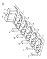
以下、本発明をその実施の形態を示す図面に基づいて説明する。図1は本実施の形態の系統連系システム100の外観構成の一例を示す模式図である。図1の例では、駐車場は、5台分の駐車スペースを有する。系統連系システム100は、駐車場に設置される電動自動車(51、52、53、54、55)用の充放電スタンド41、42、43、44、45、駐車場に設置される系統連系ユニットを備える。系統連系システム100は、事業継続計画(BCP)のための機器として提供することができる。系統連系ユニットは、蓄電池(不図示)を収容する蓄電池盤10、蓄電池PCS(Power Conditioning System)(不図示)を収容する電力変換盤20、電力系統との電力連系を行う連系制御装置(不図示)を収容する連系盤30を備える。なお、充放電スタンドの数は5個に限定されない。 (1st and 2nd embodiment)
Hereinafter, the present invention will be described with reference to the drawings showing the embodiments. FIG. 1 is a schematic diagram illustrating an example of an external configuration of asystem interconnection system 100 according to the present embodiment. In the example of FIG. 1, the parking lot has five parking spaces. The grid interconnection system 100 is a charging / discharging stand 41, 42, 43, 44, 45 for electric vehicles (51, 52, 53, 54, 55) installed in a parking lot, and a grid interconnection installed in a parking lot. It has a unit. The grid interconnection system 100 can be provided as a device for a business continuity plan (BCP). The grid connection unit includes a storage battery panel 10 that stores a storage battery (not shown), a power conversion panel 20 that stores a storage battery PCS (Power Conditioning System) (not shown), and a connection control device that performs power connection with a power system. An interconnection board 30 for accommodating (not shown) is provided. Note that the number of charge / discharge stands is not limited to five.
以下、本発明をその実施の形態を示す図面に基づいて説明する。図1は本実施の形態の系統連系システム100の外観構成の一例を示す模式図である。図1の例では、駐車場は、5台分の駐車スペースを有する。系統連系システム100は、駐車場に設置される電動自動車(51、52、53、54、55)用の充放電スタンド41、42、43、44、45、駐車場に設置される系統連系ユニットを備える。系統連系システム100は、事業継続計画(BCP)のための機器として提供することができる。系統連系ユニットは、蓄電池(不図示)を収容する蓄電池盤10、蓄電池PCS(Power Conditioning System)(不図示)を収容する電力変換盤20、電力系統との電力連系を行う連系制御装置(不図示)を収容する連系盤30を備える。なお、充放電スタンドの数は5個に限定されない。 (1st and 2nd embodiment)
Hereinafter, the present invention will be described with reference to the drawings showing the embodiments. FIG. 1 is a schematic diagram illustrating an example of an external configuration of a
電動自動車は、プラグインハイブリッド車(PHEV)又は電気自動車(EV)であり、本明細書では、PHEV又はEVとも称する。充放電スタンド41~45は、電動自動車に搭載されたバッテリ(車載用蓄電池)の充電及び放電を行うことができる。電力変換盤20に収容された蓄電池PCS(交直電力変換装置とも称する)は、交流から直流及び直流から交流の双方向に電力を変換することができ、蓄電池盤10に収容された蓄電池(定置用蓄電池とも称する)の充電及び放電を行うことができる。連系盤30に収容された連系制御装置は、電力系統が正常時には、電力系統と蓄電池PCS及び充放電スタンド41~45との系統連系運転を行い、電力系統が異常時(災害時)には、蓄電池PCS及び充放電スタンド41~45による自立運転を行うことができる。
The electric vehicle is a plug-in hybrid vehicle (PHEV) or an electric vehicle (EV), and is also referred to as PHEV or EV in this specification. The charging / discharging stands 41 to 45 can charge and discharge a battery (on-board storage battery) mounted on the electric vehicle. The storage battery PCS (also referred to as an AC / DC power conversion device) housed in the power conversion board 20 can convert power from AC to DC and from DC to AC in both directions, and the storage battery (stationary storage) housed in the storage battery board 10. (Also referred to as a storage battery). When the power system is normal, the interconnection control device housed in the interconnection board 30 performs a system interconnection operation between the power system, the storage battery PCS, and the charging / discharging stations 41 to 45, and when the power system is abnormal (at the time of disaster). , An independent operation by the storage battery PCS and the charging / discharging stands 41 to 45 can be performed.
駐車場に充放電スタンド41~45、並びに、蓄電池盤10、電力変換盤20及び連系盤30(系統連系ユニット)を設置することにより、災害時に、電動自動車が稼働しているため、電動自動車の全部又は一部が駐車場に駐車しておらず、充放電スタンド41~45から所定の負荷(重要負荷又は第1負荷とも称する)に所要の電力を供給することができない場合でも、蓄電池PCSによって蓄電池の電力を負荷に供給することができるので、全体として、負荷に対して所要の電力を供給することができる。
By installing the charging / discharging stands 41 to 45, the storage battery panel 10, the power conversion panel 20, and the interconnection panel 30 (system interconnection unit) in the parking lot, the electric vehicle is operating at the time of disaster, Even if all or a part of the automobile is not parked in the parking lot and the required power cannot be supplied from the charge / discharge stands 41 to 45 to a predetermined load (also referred to as an important load or a first load), Since the power of the storage battery can be supplied to the load by the PCS, the required power can be supplied to the load as a whole.
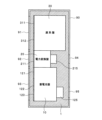
図2は本実施の形態の系統連系システム100の設置の一例を示す平面図であり、図3は本実施の形態の系統連系システム100の設置の一例を示す正面図である。図の例では、5台分の駐車スペース501~505のうち、駐車スペース501に駐車する電動自動車は駐車していないとする。符号6は衝突防止ポールであり、符号7は車輪止めである。
FIG. 2 is a plan view showing an example of installation of the grid interconnection system 100 of the present embodiment, and FIG. 3 is a front view showing an example of installation of the grid interconnection system 100 of the present embodiment. In the example of the drawing, it is assumed that the electric vehicle parked in the parking space 501 is not parked among the five parking spaces 501 to 505. Reference numeral 6 denotes a collision prevention pole, and reference numeral 7 denotes a wheel stopper.
図2に示すように、蓄電池盤10、電力変換盤20及び連系盤30は、駐車スペースの車長方向(図中、符号Lで示す方向)に沿って並べて配置される。すなわち、蓄電池盤10、電力変換盤20及び連系盤30を、駐車スペースの車長方向に沿って並べて設置することができる。駐車場の電動自動車毎に並んだ駐車スペースの車長方向に沿って蓄電池盤10、電力変換盤20及び連系盤30を並べて配置することにより、例えば、電動自動車一台分程度の駐車スペースに系統連系ユニット(蓄電池盤10、電力変換盤20及び連系盤30)を配置することができ、系統連系ユニットを含む駐車場に要する敷地面積をコンパクトにすることができる。また、系統連系ユニットと充放電スタンド41~45との間の距離を短くすることができるので、後述の電力線及び通信・制御線の配線工事及び埋設工事が容易になり工事に要するコストを低減することができる。
蓄 As shown in FIG. 2, the storage battery panel 10, the power conversion panel 20, and the interconnection panel 30 are arranged side by side along the vehicle length direction of the parking space (the direction indicated by the symbol L in the figure). That is, the storage battery panel 10, the power conversion panel 20, and the interconnection panel 30 can be arranged side by side along the vehicle length direction of the parking space. By arranging the storage battery panel 10, the power conversion panel 20, and the interconnection panel 30 along the vehicle length direction of the parking space arranged for each electric vehicle in the parking lot, for example, a parking space equivalent to one electric vehicle is provided. The grid interconnection unit (the storage battery panel 10, the power conversion panel 20, and the interconnection panel 30) can be arranged, and the site area required for the parking lot including the grid interconnection unit can be reduced. Further, since the distance between the system interconnection unit and the charging / discharging stands 41 to 45 can be shortened, wiring work and burial work for power lines and communication / control lines to be described later are facilitated, and costs required for the work are reduced. can do.
蓄電池盤10は、駐車スペース側の前面に開閉扉121、122、123を備える。電力変換盤20は、駐車スペース側の前面に開閉扉211を備える。連系盤30は、駐車スペース側の前面に開閉扉311、312を備える。すなわち、蓄電池盤10、電力変換盤20及び連系盤30それぞれに設けられた開閉扉が駐車スペース側に向くように、蓄電池盤10、電力変換盤20及び連系盤30を設置することができる。各開閉扉は、蓄電池盤10、電力変換盤20及び連系盤30の保守・点検時に開けて作業員が作業することができる。
The storage battery panel 10 is provided with opening and closing doors 121, 122, 123 on the front side on the parking space side. The power conversion panel 20 includes an opening / closing door 211 on the front surface on the parking space side. The interconnection board 30 includes opening and closing doors 311 and 312 on the front surface on the parking space side. That is, the storage battery panel 10, the power conversion panel 20, and the interconnection panel 30 can be installed such that the open / close doors provided on the storage battery panel 10, the power conversion panel 20, and the interconnection panel 30 face the parking space side. . Each opening / closing door can be opened for maintenance and inspection of the storage battery panel 10, the power conversion panel 20, and the interconnection panel 30, so that an operator can work.
例えば、図2に示すように、蓄電池盤10、電力変換盤20及び連系盤30の各開閉扉に隣接する駐車スペース501に駐車する電動自動車を駐車スペース501から移動させて、駐車スペース501を空けることにより、駐車スペース501を系統連系ユニットの保守・点検用の作業スペースとして利用することができる。これにより、予め保守・点検用の作業スペースを確保した状態で系統連系ユニットを設置する必要がなく、作業スペースを含む占有面積を小さくすることができる。
For example, as shown in FIG. 2, an electric vehicle parked in a parking space 501 adjacent to each opening / closing door of the storage battery panel 10, the power conversion panel 20, and the interconnection panel 30 is moved from the parking space 501, and the parking space 501 is By leaving the space, the parking space 501 can be used as a work space for maintenance and inspection of the system interconnection unit. Accordingly, it is not necessary to install the system interconnection unit in a state where a work space for maintenance and inspection is secured in advance, and the occupied area including the work space can be reduced.
蓄電池盤10は、駐車スペースと反対側の背面に吸排気口125を備える。電力変換盤20は、駐車スペースと反対側の背面に吸排気口215を備える。蓄電池盤10は、蓄電池の他に、蓄電池の温度管理のための冷却装置及びヒータ(不図示)を収容する。また、電力変換盤20は、蓄電池PCSの他に、蓄電池PCSの放熱のための冷却装置(不図示)を収容する。駐車スペースと反対側の背面に吸排気口を設けることにより、駐車場の利用者に対して温風などが吹き出されて当たることを抑制することができ、利用者に不快感を与えることを防止できる。
The storage battery panel 10 has an intake / exhaust port 125 on the back surface opposite to the parking space. The power conversion panel 20 includes an intake / exhaust port 215 on the back surface opposite to the parking space. The storage battery panel 10 houses a cooling device and a heater (not shown) for managing the temperature of the storage battery in addition to the storage battery. The power conversion board 20 houses a cooling device (not shown) for radiating heat of the storage battery PCS, in addition to the storage battery PCS. By providing an air intake / exhaust port on the back opposite to the parking space, it is possible to prevent hot air from blowing out and hitting the parking lot users, thereby preventing discomfort to the users it can.
蓄電池盤10、電力変換盤20及び連系盤30は、板厚が2.3mm以上とすることができる。通常、キュービクル式高圧受電設備(単にキュービクルとも称される)には、板厚が1.6mm程度の金属板が用いられる。この場合、火災予防条例上、キュービクルは、建物から3m以上離して設置する必要がある。板厚を2.3mm以上にすることにより、建物からの離隔距離が3m以上という制限がなくなる。このため、建物に隣接する駐車場に対しても、建物との離隔距離の制限を考慮せずに系統連系ユニットの配置を考えることができ、系統連系ユニットの設置の自由度が大きくなり、結果として設置が容易になる。
(4) The thickness of the storage battery panel 10, the power conversion panel 20, and the interconnection panel 30 can be 2.3 mm or more. Usually, a metal plate having a plate thickness of about 1.6 mm is used for a cubicle-type high-voltage power receiving facility (also simply referred to as a cubicle). In this case, the fire prevention regulations require that the cubicle be installed at least 3 m away from the building. By setting the plate thickness to 2.3 mm or more, the restriction that the separation distance from the building is 3 m or more is removed. For this reason, even in the parking lot adjacent to the building, it is possible to consider the arrangement of the grid interconnection unit without considering the restriction on the separation distance from the building, and the degree of freedom of installing the grid interconnection unit is increased. As a result, installation becomes easy.
図2に示すように、連系盤30の底板には、背面側に高圧引込口301、高圧引出口302を形成してあり、前面側に低圧引出口303を形成してある。高圧引込口301には、地中に埋設された電線管(例えば、可撓性を有する硬質ポリエチレン管)内を通じて配線され、電力系統の商用電源側からの電力線(高圧電源線)、及び通信・制御線が適長引き込まれる。高圧引出口302には、地中に埋設された電線管内を通じて配線され、負荷側からの電力線(高圧電源線)、及び通信・制御線が適長引き込まれる。低圧引出口303には、地中に埋設された電線管内を通じて配線され、接地線、及び充放電スタンド41~45との間の電力線(低圧電源線)及び通信・制御線が適長引き込まれる。
(2) As shown in FIG. 2, a high-pressure inlet 301 and a high-pressure outlet 302 are formed on the back side of the bottom plate of the interconnection board 30, and a low-pressure outlet 303 is formed on the front side. The high-voltage inlet 301 is wired through a conduit (for example, a rigid polyethylene tube having flexibility) buried in the ground, and is connected to a power line (high-voltage power line) from the commercial power supply side of the power system, and to a communication line. The control line is pulled in the appropriate length. The high-voltage outlet 302 is wired through a conduit buried underground, and a power line (high-voltage power line) from the load side and a communication / control line are drawn in an appropriate length. The low-pressure outlet 303 is wired through a conduit buried underground, and an appropriate length of a ground line, a power line (low-voltage power line) and a communication / control line between the charging / discharging stands 41 to 45 are drawn in.
図4は地中に埋設された電線管の一例を示す模式図である。図4において、左側の図は低圧側の掘削例を示し、右側の図は高圧側の掘削例を示す。低圧側では、5個の充放電スタンドに対応して5個の電線管それぞれに電力線(例えば、CVケーブル:架橋ポリエチレン絶縁ビニルシースケーブル)を配線するとともに、5個の充放電スタンドに対応して5個の電線管それぞれに通信・制御線を配線し、各電線管を地中の所要の深さ(例えば、60cm以上)に埋設する。高圧側では、電線管に電力線(例えば、CVケーブル)を配線するとともに、別の電線管に通信・制御線を配線し、各電線管を地中の所要の深さ(例えば、60cm以上)に埋設する。
Fig. 4 is a schematic view showing an example of a conduit tube buried underground. In FIG. 4, the figure on the left side shows an example of excavation on the low pressure side, and the figure on the right side shows an example of excavation on the high pressure side. On the low voltage side, a power line (for example, a CV cable: a crosslinked polyethylene insulated vinyl sheathed cable) is wired to each of the five conduits corresponding to the five charging / discharging stands, and 5 corresponding to the five charging / discharging stands. A communication / control line is wired to each of the conduits, and each conduit is buried at a required depth in the ground (for example, 60 cm or more). On the high voltage side, a power line (for example, a CV cable) is wired to the conduit, and a communication / control line is wired to another conduit, so that each conduit has a required underground depth (for example, 60 cm or more). Buried.
本実施の形態の系統連系システム100は、以下のようにして設置することができる。すなわち、駐車場の地盤に設けられた基礎1に、蓄電池盤10、電力変換盤20、及び連系盤30を並べて設置する。蓄電池盤10、電力変換盤20、及び連系盤30それぞれの底板(不図示)に形成されたボルト孔に、基礎1に固定された基礎ボルトを挿通してナットを締結することにより、蓄電池盤10、電力変換盤20及び連系盤30を基礎1に固定することができる。
系統 The grid interconnection system 100 of the present embodiment can be installed as follows. That is, the storage battery panel 10, the power conversion panel 20, and the interconnection panel 30 are installed side by side on the foundation 1 provided on the ground of the parking lot. By inserting a base bolt fixed to the base 1 into a bolt hole formed in a bottom plate (not shown) of each of the storage battery panel 10, the power conversion panel 20, and the interconnection panel 30, and fastening a nut, the storage battery panel 10, the power conversion board 20 and the interconnection board 30 can be fixed to the foundation 1.
系統連系ユニットを、蓄電池盤10、電力変換盤20及び連系盤30の3つの設備盤に分離することにより、設置現場に蓄電池盤10、電力変換盤20及び連系盤30を搬入する際に、大型の輸送車両が不要となる。また、設置現場で蓄電池盤10、電力変換盤20及び連系盤30を吊り上げて設置位置に移動する際に大型の重機が不要となる。特に、不特定多数の利用客が往来するショッピングモールなどの駐車場での設置においては、利用客に不便や悪印象を与えることを防止できる。また、駐車場の限られたスペースを有効利用したコンパクトな機器設置を実現することができる。
When the system interconnection unit is separated into three equipment panels of the storage battery panel 10, the power conversion panel 20, and the interconnection panel 30, when the storage battery panel 10, the power conversion panel 20, and the interconnection panel 30 are carried into the installation site. In addition, a large transport vehicle is not required. Further, when the storage battery panel 10, the power conversion panel 20, and the interconnection panel 30 are lifted and moved to the installation position at the installation site, a large heavy machine is not required. In particular, in the case of installation in a parking lot such as a shopping mall where an unspecified number of customers come and go, it is possible to prevent inconvenience and bad impression to the users. In addition, it is possible to realize compact equipment installation that makes effective use of the limited space of the parking lot.
また、連系盤30の高圧引込口301を通じて商用電源からのケーブルを接続し、連系盤30の高圧引出口302を通じて所定の負荷へのケーブルを接続し、連系盤30の低圧引出口303を通じて充放電スタンド41~45からのケーブルを接続する。ケーブルには、電力線及び通信・制御線が含まれる。低圧側配線と通信・制御線の線長は、系統連系ユニットのパッケージ設計により想定可能なため、予め線加工したものを用意することができる。
Further, a cable from a commercial power supply is connected through a high-pressure outlet 301 of the interconnection panel 30, a cable to a predetermined load is connected through a high-pressure outlet 302 of the interconnection panel 30, and a low-pressure outlet 303 of the interconnection panel 30 is connected. To connect the cables from the charging / discharging stands 41 to 45. The cable includes a power line and a communication / control line. Since the line lengths of the low-voltage side wiring and the communication / control line can be assumed by the package design of the system interconnection unit, a line processed in advance can be prepared.
上述の構成により、系統連系ユニットの設置工事を比較的短時間で行うことができ、工事費用を低減することができる。
に よ り With the above configuration, the installation work of the grid interconnection unit can be performed in a relatively short time, and the construction cost can be reduced.
また、駐車場の地盤に設けられた基礎1に、充放電スタンド41~45を複数並べて設置することができる。系統連系ユニットが、駐車スペースに隣接して設置されるので、系統連系ユニットと充放電スタンド41~45との間の距離を短くすることができるので、電力線及び通信線の配線工事及び埋設工事が容易になり工事に要するコストを低減することができる。
複数 Further, a plurality of charging / discharging stands 41 to 45 can be arranged side by side on the foundation 1 provided on the ground of the parking lot. Since the grid interconnection unit is installed adjacent to the parking space, the distance between the grid interconnection unit and the charging / discharging stands 41 to 45 can be shortened. Construction is facilitated, and costs required for the construction can be reduced.
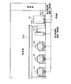
図5は系統連系ユニットの周囲に設置された装飾壁90の配置例を示す平面図である。図5に示すように、装飾壁90を、蓄電池盤10、電力変換盤20及び連系盤30が据え付けられる基礎1に、蓄電池盤10、電力変換盤20及び連系盤30の周囲を覆うように設置することができる。装飾壁90は、広告やアートなどが表示された表示板とすることができる。装飾壁90は、蓄電池盤10、電力変換盤20及び連系盤30が見えない程度の高さとすることができる。ショッピングモールや公共の場所では、蓄電池盤10、電力変換盤20及び連系盤30の外観は、利用者に若干の違和感を与える可能性が高い。そこで、装飾壁90で蓄電池盤10、電力変換盤20及び連系盤30を覆うことにより、利用者に違和感を与えることなく、また利用者に興味を抱かせるような情報を表示することができる。
FIG. 5 is a plan view showing an example of the arrangement of the decorative wall 90 installed around the system interconnection unit. As shown in FIG. 5, the decorative wall 90 is provided on the foundation 1 on which the storage battery panel 10, the power conversion panel 20 and the interconnection panel 30 are installed so as to cover the periphery of the storage battery panel 10, the power conversion panel 20 and the interconnection panel 30. Can be installed in The decorative wall 90 can be a display panel on which an advertisement, art, or the like is displayed. The decorative wall 90 can be so high that the storage battery panel 10, the power conversion panel 20 and the interconnection panel 30 are not visible. In a shopping mall or a public place, the external appearances of the storage battery panel 10, the power conversion panel 20, and the interconnection panel 30 are likely to give the user some uncomfortable feeling. Therefore, by covering the storage battery panel 10, the power conversion panel 20, and the interconnection panel 30 with the decorative wall 90, it is possible to display information that does not give a user a sense of incongruity and that interests the user. .
装飾壁90の駐車スペース側の前面には、蓄電池盤10の開閉扉121、122、123の位置に対応させて出入口93を設けている。装飾壁90の駐車スペース側の前面には、電力変換盤20の開閉扉211の位置に対応させて出入口92を設けている。また、装飾壁90の駐車スペース側の前面には、連系盤30の開閉扉311、312の位置に対応させて出入口91を設けている。出入口91~93は、開閉可能な扉でもよく、着脱可能な壁板でもよい。これにより、装飾壁90で蓄電池盤10、電力変換盤20及び連系盤30の周囲を覆っても、蓄電池盤10、電力変換盤20及び連系盤30の保守・点検を行うことができる。
出 An entrance / exit 93 is provided on the front side of the decorative wall 90 on the parking space side in correspondence with the positions of the open / close doors 121, 122 and 123 of the storage battery panel 10. An entrance / exit 92 is provided on the front surface of the decorative wall 90 on the parking space side in correspondence with the position of the opening / closing door 211 of the power conversion panel 20. An entrance / exit 91 is provided on the front side of the decorative wall 90 on the parking space side in correspondence with the positions of the open / close doors 311 and 312 of the interconnection panel 30. The entrances 91 to 93 may be openable and closable doors or detachable wall boards. Thereby, even if the surroundings of the storage battery panel 10, the power conversion panel 20, and the interconnection panel 30 are covered with the decorative wall 90, the maintenance and inspection of the storage battery panel 10, the power conversion panel 20, and the interconnection panel 30 can be performed.
装飾壁90の駐車スペースの反対側の背面は、蓄電池盤10の吸排気口125の位置に対応させて開口95を設けている。また、装飾壁90の駐車スペースの反対側の背面は、電力変換盤20の吸排気口215の位置に対応させて開口94を設けている。開口94、95は、パンチング又はスリットなどを設けることができる。開口94、95を設けることにより、装飾壁90で蓄電池盤10、電力変換盤20及び連系盤30の周囲を覆っても、蓄電池盤10、電力変換盤20及び連系盤30の冷却を行うことができる。
開口 An opening 95 is provided on the back surface of the decorative wall 90 opposite to the parking space in correspondence with the position of the air intake / exhaust port 125 of the storage battery panel 10. An opening 94 is provided on the back surface of the decorative wall 90 opposite to the parking space, corresponding to the position of the air intake / exhaust port 215 of the power converter panel 20. The openings 94 and 95 can be provided with punching or slits. By providing the openings 94 and 95, the storage battery panel 10, the power conversion panel 20, and the interconnection panel 30 are cooled even when the decoration wall 90 covers the periphery of the storage battery panel 10, the power conversion panel 20, and the interconnection panel 30. be able to.
図5の例では、装飾壁90を蓄電池盤10、電力変換盤20及び連系盤30の周囲の4面に亘って、すべて覆う構成であるが、これに限定されない。例えば、4面のうち2面だけを覆うようにしてもよい。例えば、2面だけを覆う場合、蓄電池盤10側と背面側の2面を覆うことができる。蓄電池盤10側は、利用者の目に一番入りやすく、また背面は各盤の大きさの不一致を隠すことができる。また、2面にすることにより、4面の場合よりもコストを削減することができる。
(5) In the example of FIG. 5, the decorative wall 90 is entirely covered over the four surfaces around the storage battery panel 10, the power conversion panel 20, and the interconnection panel 30, but is not limited thereto. For example, only two of the four surfaces may be covered. For example, when only two surfaces are covered, two surfaces on the storage battery panel 10 side and the back side can be covered. The storage battery panel 10 side is most easily seen by the user, and the back side can hide the mismatch in the size of each panel. Further, by using two planes, the cost can be reduced as compared with the case of four planes.
図2の例では、5台分の駐車スペース501~505のうち、一番端の駐車スペース501に隣接する位置に蓄電池盤10、電力変換盤20及び連系盤30を並べて設置する構成であったが、設置は図2の例に限定されない。例えば、駐車スペース502と駐車スペース503との間に略1台分の駐車スペースに相当する区画を設け、その区画に蓄電池盤10、電力変換盤20及び連系盤30を並べて設置してもよい。
In the example of FIG. 2, the storage battery panel 10, the power conversion panel 20, and the interconnection panel 30 are arranged side by side at a position adjacent to the endmost parking space 501 among the five parking spaces 501 to 505. However, the installation is not limited to the example of FIG. For example, a partition corresponding to approximately one parking space may be provided between the parking space 502 and the parking space 503, and the storage battery panel 10, the power conversion panel 20, and the interconnection panel 30 may be arranged in the partition. .
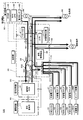
図6は本実施の形態の系統連系システム100の回路構成の一例を示す模式図である。蓄電池盤10は、蓄電池(定置蓄電池)11、不図示の制御装置、冷却装置及びヒータなどを収容する。電力変換盤20は、蓄電池PCS21、不図示の制御装置及び冷却装置などを収容する。連系盤30は、連系制御装置36の他に、リモートIO31、開閉部としてのVCB32、変圧器33、UVR34、計器用変圧器35などを備える。
FIG. 6 is a schematic diagram showing an example of a circuit configuration of the interconnection system 100 of the present embodiment. The storage battery panel 10 houses a storage battery (stationary storage battery) 11, a control device (not shown), a cooling device, a heater, and the like. The power conversion board 20 houses a storage battery PCS21, a control device (not shown), a cooling device, and the like. The interconnection board 30 includes, in addition to the interconnection control device 36, a remote IO 31, a VCB 32 as an opening / closing unit, a transformer 33, a UVR 34, an instrument transformer 35, and the like.
連系盤30は、端子台101、102、及びブレーカ103、104、111~115を備える。端子台101は、高圧引込側の電路(高圧電源線)に設けられている。すなわち、端子台101には、電力系統の降圧トランス85の二次側からの電力線、及び一般負荷(第2負荷)に接続される降圧トランス86の一次側からの電力線が接続される。ここで、一般負荷は、例えば、災害時に電力が遮断されても、比較的影響が少ない電気機器を含む。
The interconnection board 30 includes terminal blocks 101 and 102 and breakers 103, 104 and 111 to 115. The terminal block 101 is provided on an electric circuit (high-voltage power supply line) on the high-voltage lead-in side. That is, the power line from the secondary side of the step-down transformer 85 of the power system and the power line from the primary side of the step-down transformer 86 connected to the general load (second load) are connected to the terminal block 101. Here, the general load includes, for example, an electric device that has relatively little effect even if the power is cut off during a disaster.
端子台102は、高圧引出側の電路(高圧電源線)に設けられている。すなわち、端子台102は、重要負荷(第1負荷)に接続される降圧トランス87の一次側からの電力線が接続される。ここで、重要負荷は、災害時でも電力を継続して供給する必要性がある重要な負荷(重要負荷)であり、例えば、非常用のエレベータ、連続運転が必要な電気機器、建屋の照明や空調機器などが含まれる。
(4) The terminal block 102 is provided on an electric circuit (high-voltage power supply line) on the high-voltage extraction side. That is, the terminal block 102 is connected to a power line from the primary side of the step-down transformer 87 connected to the important load (first load). Here, the important load is an important load (important load) for which it is necessary to continuously supply power even in the event of a disaster, such as an emergency elevator, electric equipment that requires continuous operation, lighting of a building, Includes air conditioning equipment.
端子台101には、断路器37を介して、VCB32の一方の電極、UVR34、計器用変圧器35が接続されている。計器用変圧器35については後述する。VCB32は、真空遮断器であり、電極を高真空の容器内に収容し、電流を遮断する際に電極間に発生するアーク放電を構成する物質を高真空内で拡散させてアークを消滅させる遮断器である。
One terminal of the VCB 32, the UVR 34, and the instrument transformer 35 are connected to the terminal block 101 via the disconnector 37. The instrument transformer 35 will be described later. The VCB 32 is a vacuum circuit breaker, in which electrodes are accommodated in a high-vacuum container, and a substance constituting an arc discharge generated between the electrodes when current is interrupted is diffused in high vacuum to extinguish the arc. It is a vessel.
UVR34は、不足電圧継電器であり、電力系統側の短絡事故、停電などの異常を検出することができる。UVR34は、異常を検出した場合、VCB32へ制御信号を出力し、VCB32の電路を遮断させる。
The UVR 34 is an undervoltage relay, and can detect an abnormality such as a short circuit accident or a power failure on the power system side. When detecting an abnormality, the UVR 34 outputs a control signal to the VCB 32 to cut off the electric circuit of the VCB 32.
また、系統連系システムを用いて電力需要管理を行う建物には、降圧トランス85の一次側の電力を監視する電力監視ユニット80が設けられている。なお、電力監視ユニット80は、必ずしも必須ではない。また、降圧トランス85が設置されていない場合には、電力監視ユニット80が監視する箇所は適宜設定される。電力監視ユニット80は、OVGR81、RPR/UPR82、電力センサ83を備える。OVGR81は、地絡過電圧継電器であり、電力系統の地絡事故の継続検出を行う。RPR/UPR82は、逆電力継電器及び不足電力継電器であり、電力系統側への逆潮流や短絡事故などの異常を検出することができる。OVGR81、RPR/UPR82で異常を検出した場合にも、VCB32の電路が遮断される。
In addition, a power monitoring unit 80 that monitors the power on the primary side of the step-down transformer 85 is provided in a building that manages power demand using the grid interconnection system. The power monitoring unit 80 is not always essential. When the step-down transformer 85 is not installed, the position monitored by the power monitoring unit 80 is appropriately set. The power monitoring unit 80 includes an OVGR 81, an RPR / UPR 82, and a power sensor 83. The OVGR 81 is a ground fault overvoltage relay, and continuously detects a ground fault in the power system. The RPR / UPR 82 is a reverse power relay and a power shortage relay, and can detect an abnormality such as a reverse power flow to the power system or a short circuit accident. Even when an abnormality is detected in the OVGR 81 and the RPR / UPR 82, the electric circuit of the VCB 32 is cut off.
リモートIO31は、電力センサ83で検出した電力(アナログ値)をデジタル値に変換するAD変換器であり、変換後の電力(デジタル値)を連系制御装置36へ出力する。
The remote IO 31 is an AD converter that converts the power (analog value) detected by the power sensor 83 into a digital value, and outputs the converted power (digital value) to the interconnection control device 36.
VCB32の他方の電極には、電路を介して変圧器33(より具体的には、第1巻線331)が接続されている。変圧器33は、第1巻線331、電路を介してブレーカ103に接続される第2巻線332、電路を介してブレーカ111~115に接続される第3巻線333を備える。
A transformer 33 (more specifically, a first winding 331) is connected to the other electrode of the VCB 32 via an electric path. The transformer 33 includes a first winding 331, a second winding 332 connected to the breaker 103 via an electric path, and a third winding 333 connected to the breakers 111 to 115 via an electric path.
すなわち、変圧器33は、3相の3巻線変圧器とすることができる。第1巻線331側の電圧及び電力(皮相電力)は、例えば、6600V、50kVAとすることができ、第2巻線332側の電圧及び電力は、例えば、300V、50kVAとすることができ、第3巻線333側の電圧及び電力は、例えば、210V、50kVAとすることができるが、電圧及び電力は、これらの値に限定されない。変圧器33を3巻線変圧器とすることにより、変圧器を二つ設ける場合に比べて省スペース化、軽量化を図ることができる。
That is, the transformer 33 can be a three-phase three-winding transformer. The voltage and power (apparent power) on the first winding 331 side can be, for example, 6600 V, 50 kVA, and the voltage and power on the second winding 332 side can be, for example, 300 V, 50 kVA, The voltage and the power on the third winding 333 side can be, for example, 210 V and 50 kVA, but the voltage and the power are not limited to these values. By using the transformer 33 as a three-winding transformer, it is possible to save space and weight as compared with a case where two transformers are provided.
ブレーカ103には、蓄電池PCS21が接続される。蓄電池PCS21は、交流から直流及び直流から交流の双方向に電力を変換することができ、蓄電池11の充電及び放電を行うことができる。
The storage battery PCS21 is connected to the breaker 103. The storage battery PCS21 can convert electric power in both directions from AC to DC and from DC to AC, and can charge and discharge the storage battery 11.
ブレーカ104には、第3巻線333の3相のうちの1相の電路が接続され、例えば、105V~210Vの電圧が、電力変換盤20内の制御装置及び冷却装置用の電源として、さらに蓄電池盤10内の制御装置、冷却装置及びヒータ用の電源として供給される。
The breaker 104 is connected to an electric circuit of one of the three phases of the third winding 333. For example, a voltage of 105 V to 210 V is used as a power supply for a control device and a cooling device in the power conversion board 20. It is supplied as a power supply for the control device, cooling device and heater in the storage battery panel 10.
ブレーカ111~115それぞれには、充放電スタンド41~45からの電力線が接続される。充放電スタンド41~45は、交流から直流及び直流から交流の双方向に電力を変換することができる変換回路を備え、電動自動車51~55に搭載されたバッテリの充電及び放電を行うことができる。
The power lines from the charging / discharging stands 41 to 45 are connected to the breakers 111 to 115, respectively. Each of the charging / discharging stands 41 to 45 includes a conversion circuit that can convert electric power in both directions from AC to DC and from DC to AC, and can charge and discharge a battery mounted on the electric vehicles 51 to 55. .
充放電スタンド41~45は、電動自動車51~54のバッテリの充放電に関する情報を通知する通知部(不図示)を備える。通知部は、例えば、表示パネル又は表示灯でもよく、あるいは無線通信を介して、ユーザ又は管理者などが使用する端末装置へ通知してもよい。充放電に関する情報は、例えば、充放電の準備中、準備完了、充放電中、充放電完了などの動作状態、バッテリの充電状態(SOC)、満充電にするための所要時間、満充電になるまでの残余時間、放電可能量、充放電に関する料金などの情報を含めることができる。これにより、電動自動車の充放電に関する情報をタイムリーに把握することができる。
The charging / discharging stands 41 to 45 include a notifying unit (not shown) for notifying information regarding charging and discharging of the batteries of the electric vehicles 51 to 54. The notification unit may be, for example, a display panel or an indicator light, or may notify a terminal device used by a user or an administrator via wireless communication. The information on charge / discharge includes, for example, an operation state such as preparation for charge / discharge, preparation completion, charge / discharge, charge / discharge completion, a state of charge (SOC) of the battery, a required time for full charge, and a full charge. Information such as the remaining time until, the dischargeable amount, and the charge for charging and discharging can be included. This makes it possible to timely grasp information on charging and discharging of the electric vehicle.
次に、本実施の形態の系統連系システム100による系統連系方法について説明する。
Next, a grid connection method using the grid connection system 100 of the present embodiment will be described.
図7は本実施の形態の系統連系システム100による電力系統が正常時の系統連系の第1例を示す模式図である。連系制御装置36は、電力系統が正常時であって、充電モードが設定されている場合には、充放電スタンド41~45により電動自動車51~55を充電することができる。これにより、系統連系システム100を電動自動車の急速充電スタンドとして利用することができる。
FIG. 7 is a schematic diagram showing a first example of system interconnection when the electric power system is normal by the interconnection system 100 of the present embodiment. The interconnection control device 36 can charge the electric vehicles 51 to 55 by the charge / discharge stands 41 to 45 when the power system is normal and the charging mode is set. Thereby, the system interconnection system 100 can be used as a quick charging station for an electric vehicle.
また、図示していないが、電力系統が正常時には、商用電源から重要負荷に電力が供給される。また、電力系統が正常時には、商用電源から一般負荷に電力が供給される。
Although not shown, when the power system is normal, power is supplied from the commercial power supply to the important load. When the power system is normal, power is supplied from a commercial power supply to a general load.
負荷を一般負荷と重要負荷との二つの系統に分けることにより、後述する災害時に供給する電力を必要最小限とし、重要負荷へ電力を継続して供給するとともに、重要負荷に電力を供給できる時間を長くすることができる。
By dividing the load into two systems, a general load and an important load, the power to be supplied in the event of a disaster described below is minimized, and the time during which power can be continuously supplied to the important load and the power can be supplied to the important load Can be lengthened.
図8は本実施の形態の系統連系システム100による電力系統が正常時の系統連系の第2例を示す模式図である。連系制御装置36は、電力系統が正常時であって、エネマネモード(エネルギーマネジメントモード)に設定された状態で、所定箇所の受電点電力が閾値以上である場合、例えば、電力センサ83で検出した電力が閾値以上である場合、閾値以下になるように、充放電スタンド41~45から重要負荷及び一般負荷に電力を供給する、あるいは、蓄電池PCS21から重要負荷及び一般負荷に電力を供給する。これにより、電力のピークカット運転が可能になる。なお、所定箇所の受電点電力が閾値以下である場合は、閾値を超えない範囲で、電力系統から充放電スタンド41~45、もしくは、蓄電池PCS21に電力を供給することができる。
FIG. 8 is a schematic diagram showing a second example of system interconnection when the power system is normal by the interconnection system 100 of the present embodiment. The interconnection control device 36 detects, for example, with the power sensor 83 when the power receiving point power at a predetermined location is equal to or greater than a threshold value in a state where the power system is normal and in the energy management mode (energy management mode). When the power is equal to or higher than the threshold, the power is supplied from the charge / discharge stations 41 to 45 to the important load and the general load, or the power is supplied from the storage battery PCS21 to the important load and the general load so that the power becomes equal to or lower than the threshold. Thereby, peak cut operation of electric power becomes possible. When the power at the power receiving point at the predetermined location is equal to or less than the threshold, power can be supplied from the power system to the charging / discharging stations 41 to 45 or the storage battery PCS21 within a range not exceeding the threshold.
図9は本実施の形態の系統連系システム100による電力系統が非常時の自立運転の一例を示す模式図である。連系制御装置36は、電力系統が非常時には、VCB32の電極を開いて商用電源と重要負荷とを切り離す。この状態で、充放電スタンド41~45、もしくは、蓄電池PCS21から電力を供給することにより、連系制御装置36による自立運転を可能にすることができる。
FIG. 9 is a schematic diagram showing an example of the self-sustaining operation when the power system by the grid interconnection system 100 of the present embodiment is in an emergency. When the power system is in an emergency, the interconnection control device 36 opens the electrode of the VCB 32 to disconnect the commercial power supply from the important load. In this state, by supplying electric power from the charging / discharging stands 41 to 45 or the storage battery PCS21, the independent operation by the interconnection control device 36 can be enabled.
連系制御装置36は、電力系統が非常時には、充放電スタンド41~45又は蓄電池PCS21の少なくとも一方から重要負荷に電力を供給することができる。
The interconnection control device 36 can supply power to the important load from at least one of the charging / discharging stations 41 to 45 or the storage battery PCS21 when the power system is in an emergency.
なお、連系制御装置36が自立運転を行う場合、蓄電池PCS21は電圧制御を行い電圧源として動作する。所要の電力を得るために必要な電流は、電圧源として動作する蓄電池PCS21に充放電スタンド41~45が連系し電流源として動作することにより実現される。
(4) When the interconnection control device 36 performs an independent operation, the storage battery PCS21 performs voltage control and operates as a voltage source. The current required to obtain the required power is realized by the charging / discharging stations 41 to 45 being linked to the storage battery PCS21 operating as a voltage source and operating as a current source.
上述の構成により、災害時に、電動自動車が稼働しているため、充放電スタンド41~45から重要負荷に所要の電力を供給することができない場合でも、蓄電池PCS21から重要負荷に電力を供給することができるので、全体として、電力系統の重要負荷に対して所要の電力を供給することができる。
With the above-described configuration, even when the electric vehicle is operating at the time of a disaster and the required power cannot be supplied from the charge / discharge stands 41 to 45 to the important load, the power can be supplied from the storage battery PCS21 to the important load. Therefore, the required power can be supplied to the important load of the power system as a whole.
より具体的には、連系制御装置36は、電力系統が非常時の場合に、充放電スタンド41~45から供給できる電力が重要負荷の容量を超える場合、充放電スタンド41~45から蓄電池PCS21に余剰電力を供給する。これにより、電動自動車が駐車スペースに駐車し、稼働していない場合、電動自動車の電力を有効利用することができる。
More specifically, when the power system is in an emergency and the power that can be supplied from the charging / discharging stations 41 to 45 exceeds the capacity of the important load, the interconnection control device 36 transmits the storage battery PCS21 from the charging / discharging stations 41 to 45. To supply surplus power. Accordingly, when the electric vehicle is parked in the parking space and is not operating, the electric power of the electric vehicle can be effectively used.
また、連系制御装置36は、電力系統が非常時の場合に、充放電スタンド41~45から供給できる電力が重要負荷の容量未満の場合、充放電スタンド41~45及び蓄電池PCS21の両方から重要負荷に電力を供給する。例えば、重要負荷の容量が50kVAとし、充放電スタンド41~45から全体で30kVAの電力を供給することができる場合には、蓄電池PCS21から20kVAの電力を供給して、変圧器33の高圧側から50kVAの電力を重要負荷に供給することができる。重要負荷の容量が変化した場合には、重要負荷の容量に適した電力だけを供給することができる。これにより、所要台数の電動自動車の全部又は一部が駐車スペースに駐車しておらず稼働中である場合、不足分の電力を蓄電池PCS21から供給することができ、電力系統の重要負荷に対して所要の電力を供給することができる。
When the power system is in an emergency and the power that can be supplied from the charging / discharging stations 41 to 45 is less than the capacity of the important load, the interconnection control device 36 determines whether the power from the charging / discharging stations 41 to 45 and the storage battery PCS21 is important. Supply power to the load. For example, when the capacity of the important load is 50 kVA and the power of 30 kVA can be supplied from the charging / discharging stations 41 to 45 in total, the power of 20 kVA is supplied from the storage battery PCS 21 and the high voltage side of the transformer 33 is used. 50 kVA of power can be supplied to critical loads. When the capacity of the important load changes, only electric power suitable for the capacity of the important load can be supplied. Thereby, when all or a part of the required number of electric vehicles is not parked in the parking space and is in operation, the shortage of power can be supplied from the storage battery PCS21, and the important load of the power system can be reduced. The required power can be supplied.
図10は本実施の形態の系統連系システム100による電力系統が非常時から正常時に復帰する場合の運転切替の一例を示す模式図である。連系制御装置36は、電力系統が復電した場合、充放電スタンド41~45又は蓄電池PCS21の少なくとも一方から重要負荷に供給する電力を、無瞬断で商用電源からの電力に切り替える。無瞬断切替は、例えば、計器用変圧器35で商用電源の位相を検出し、蓄電池PCS21の位相が商用電源の位相と同期したタイミングでVCB32の電極を閉じることにより、商用電源からの電力を重要負荷に供給する。
FIG. 10 is a schematic diagram illustrating an example of operation switching when the power system returns from an emergency to a normal state by the grid interconnection system 100 of the present embodiment. When the power system is restored, the interconnection control device 36 switches the power supplied to the important load from at least one of the charging / discharging stations 41 to 45 or the storage battery PCS21 to the power from the commercial power supply without an instantaneous interruption. The instantaneous interruption switching is performed, for example, by detecting the phase of the commercial power supply with the instrument transformer 35 and closing the electrode of the VCB 32 at the timing when the phase of the storage battery PCS21 is synchronized with the phase of the commercial power supply, thereby reducing the power from the commercial power supply. Supply critical loads.
商用電源が重要負荷に無瞬断で再接続された後、連系制御装置36は、充放電スタンド41~45及び蓄電池PCS21の動作を停止し、自立運転を終了する。蓄電池PCS21が電圧制御を行っているので、無瞬断切替が可能となる。その後、連系制御装置36は、系統連系を行うべく、充放電スタンド41~45及び蓄電池PCS21を再起動することができる。これにより、位相を同期させて、無瞬断で切り替えることにより、重要負荷に対して安定した電力を供給することができる。
(4) After the commercial power supply is reconnected to the important load without an instantaneous interruption, the interconnection control device 36 stops the operations of the charging / discharging stations 41 to 45 and the storage battery PCS21 and ends the self-sustaining operation. Since the storage battery PCS21 performs voltage control, instantaneous interruption switching can be performed. Thereafter, the interconnection control device 36 can restart the charging / discharging stands 41 to 45 and the storage battery PCS21 in order to perform the interconnection. As a result, stable power can be supplied to the important load by synchronizing the phases and switching without instantaneous interruption.
上述の実施の形態では、電力系統の連系を6600Vの高圧で行う構成であったが、これに限定されるものではなく、低圧で連系するようにしてもよい。低圧とする場合は、50kVA未満とする必要があるので、変圧器33の第1巻線331側の電圧及び電力(皮相電力)は、例えば、210V、49kVAとすることができ、第2巻線332側の電圧及び電力(皮相電力)は、例えば、300V、49kVAとすることができ、第3巻線333側の電圧及び電力(皮相電力)は、例えば、210V、49kVAとすることができる。また、変圧器は、3巻線変圧器に限定されるものではなく、2巻線変圧器を2つ備える構成でもよい。
In the above-described embodiment, the power system is connected at a high voltage of 6600 V. However, the present invention is not limited to this, and the power system may be connected at a low voltage. When the voltage is low, the voltage and the power (apparent power) on the first winding 331 side of the transformer 33 can be set to, for example, 210 V and 49 kVA. The voltage and power (apparent power) on the 332 side can be, for example, 300 V and 49 kVA, and the voltage and power (apparent power) on the third winding 333 side can be, for example, 210 V and 49 kVA. Further, the transformer is not limited to the three-winding transformer, and may have a configuration including two two-winding transformers.
(第3実施形態)
図11は本実施の形態の系統連系システム100の外観構成の一例を示す模式図である。図11の例では、駐車場は、4台分の駐車スペースを有する。駐車場には、カーポート500が設置され、カーポートの上面には太陽電池(太陽電池パネル)510が取り付けられている。系統連系システム100は、駐車場に設置される電動自動車(51、52、53、54)用の充放電スタンド41、42、43、44、駐車場に設置される太陽電池510用の後述のインバータ装置520、駐車場に設置される系統連系ユニットを備える。系統連系システム100は、事業継続計画(BCP)のための機器として提供することができる。系統連系ユニットは、蓄電池(不図示)を収容する蓄電池盤10、蓄電池PCS(Power Conditioning System)(不図示)を収容する電力変換盤20、電力系統との系統連系を行う連系制御装置(不図示)を収容する連系盤30を備える。なお、充放電スタンドの数は4個に限定されない。連系制御装置は、電力系統と、蓄電池PCS、充放電スタンド及びインバータ装置の少なくとも一つとの間で系統連系を行うことができる。 (Third embodiment)
FIG. 11 is a schematic diagram illustrating an example of an external configuration of asystem interconnection system 100 according to the present embodiment. In the example of FIG. 11, the parking lot has four parking spaces. A carport 500 is installed in the parking lot, and a solar cell (solar cell panel) 510 is mounted on the upper surface of the carport. The grid interconnection system 100 includes charge / discharge stands 41, 42, 43, 44 for electric vehicles (51, 52, 53, 54) installed in a parking lot, and a solar battery 510 installed in a parking lot, which will be described later. The inverter device 520 includes a system interconnection unit installed in a parking lot. The grid interconnection system 100 can be provided as a device for a business continuity plan (BCP). The system interconnection unit includes a storage battery panel 10 that accommodates a storage battery (not shown), a power conversion panel 20 that accommodates a storage battery PCS (Power Conditioning System) (not shown), and an interconnection control device that performs system interconnection with a power system. An interconnection board 30 for accommodating (not shown) is provided. Note that the number of charge / discharge stands is not limited to four. The interconnection control device can perform interconnection between the electric power system and at least one of the storage battery PCS, the charging / discharging stand, and the inverter device.
図11は本実施の形態の系統連系システム100の外観構成の一例を示す模式図である。図11の例では、駐車場は、4台分の駐車スペースを有する。駐車場には、カーポート500が設置され、カーポートの上面には太陽電池(太陽電池パネル)510が取り付けられている。系統連系システム100は、駐車場に設置される電動自動車(51、52、53、54)用の充放電スタンド41、42、43、44、駐車場に設置される太陽電池510用の後述のインバータ装置520、駐車場に設置される系統連系ユニットを備える。系統連系システム100は、事業継続計画(BCP)のための機器として提供することができる。系統連系ユニットは、蓄電池(不図示)を収容する蓄電池盤10、蓄電池PCS(Power Conditioning System)(不図示)を収容する電力変換盤20、電力系統との系統連系を行う連系制御装置(不図示)を収容する連系盤30を備える。なお、充放電スタンドの数は4個に限定されない。連系制御装置は、電力系統と、蓄電池PCS、充放電スタンド及びインバータ装置の少なくとも一つとの間で系統連系を行うことができる。 (Third embodiment)
FIG. 11 is a schematic diagram illustrating an example of an external configuration of a
電動自動車は、プラグインハイブリッド車(PHEV)又は電気自動車(EV)であり、本明細書では、PHEV又はEVとも称する。充放電スタンド41~44は、電動自動車に搭載されたバッテリ(車載用蓄電池)の充電及び放電を行うことができる。インバータ装置520は、直流を交流に変換することができ、太陽電池510からの直流を交流に変換して出力する。すなわち、インバータ装置520は、太陽電池510のエネルギーを放電することができる。電力変換盤20に収容された蓄電池PCS(交直電力変換装置とも称する)は、交流から直流及び直流から交流の双方向に電力を変換することができ、蓄電池盤10に収容された蓄電池(定置用蓄電池とも称する)の充電及び放電を行うことができる。連系盤30に収容された連系制御装置は、電力系統が正常時には、電力系統と蓄電池PCS、充放電スタンド41~44及びインバータ装置520との系統連系運転を行い、電力系統が異常時(災害時)には、蓄電池PCS、充放電スタンド41~44及びインバータ装置520による自立運転を行うことができる。
The electric vehicle is a plug-in hybrid vehicle (PHEV) or an electric vehicle (EV), and is also referred to as PHEV or EV in this specification. The charge / discharge stands 41 to 44 can charge and discharge a battery (on-board storage battery) mounted on the electric vehicle. The inverter device 520 can convert DC to AC, and converts DC from the solar cell 510 to AC and outputs the AC. That is, the inverter device 520 can discharge the energy of the solar cell 510. The storage battery PCS (also referred to as an AC / DC power conversion device) housed in the power conversion board 20 can convert power from AC to DC and from DC to AC in both directions, and the storage battery (stationary storage) housed in the storage battery board 10. (Also referred to as a storage battery). When the power system is normal, the interconnection control device housed in the interconnection panel 30 performs system interconnection operation between the power system and the storage battery PCS, the charging / discharging stations 41 to 44, and the inverter device 520, and when the power system is abnormal. At the time of a disaster, the storage battery PCS, the charging / discharging stands 41 to 44, and the inverter device 520 can be operated independently.
駐車場に充放電スタンド41~44及びインバータ装置、並びに、蓄電池盤10、電力変換盤20及び連系盤30(系統連系ユニット)を設置することにより、災害時に、電動自動車が稼働しているため、電動自動車の全部又は一部が駐車場に駐車しておらず、充放電スタンド41~44から所定の負荷(重要負荷又は第1負荷とも称する)に所要の電力を供給することができない場合、あるいはインバータ装置520から供給できる電力が少ない場合、より具体的には、充放電スタンド41~44及びインバータ装置520から重要負荷に所要の電力を供給することができない場合でも、蓄電池PCSによって蓄電池の電力を負荷に供給することができるので、全体として、負荷に対して所要の電力を供給することができる。
By installing the charging / discharging stands 41 to 44, the inverter device, the storage battery panel 10, the power conversion panel 20, and the interconnection panel 30 (system interconnection unit) in the parking lot, the electric vehicle is operating at the time of disaster. Therefore, when all or a part of the electric vehicle is not parked in the parking lot, and the required power cannot be supplied from the charge / discharge stands 41 to 44 to a predetermined load (also referred to as an important load or a first load). Or, when the power that can be supplied from the inverter device 520 is small, more specifically, even when it is not possible to supply the required power to the important load from the charging / discharging stations 41 to 44 and the inverter device 520, the storage battery PCS Since power can be supplied to the load, required power can be supplied to the load as a whole.
図12は本実施の形態の系統連系システム100の設置の一例を示す平面図であり、図13は本実施の形態の系統連系システム100の設置の一例を示す正面図である。図の例では、4台分の駐車スペース501~504のうち、駐車スペース501に駐車する電動自動車は駐車していないとする。符号6は衝突防止ポールであり、符号7は車輪止めである。
FIG. 12 is a plan view showing an example of installation of the grid interconnection system 100 of the present embodiment, and FIG. 13 is a front view showing an example of installation of the grid interconnection system 100 of the present embodiment. In the example of the drawing, it is assumed that the electric vehicle parked in the parking space 501 is not parked among the four parking spaces 501 to 504. Reference numeral 6 denotes a collision prevention pole, and reference numeral 7 denotes a wheel stopper.
図12に示すように、蓄電池盤10、電力変換盤20及び連系盤30は、駐車スペースの車長方向(図中、符号Lで示す方向)に沿って並べて配置される。すなわち、蓄電池盤10、電力変換盤20及び連系盤30を、駐車スペースの車長方向に沿って並べて設置することができる。駐車場の電動自動車毎に並んだ駐車スペースの車長方向に沿って蓄電池盤10、電力変換盤20及び連系盤30を並べて配置することにより、例えば、電動自動車一台分程度の駐車スペースに系統連系ユニット(蓄電池盤10、電力変換盤20及び連系盤30)を配置することができ、系統連系ユニットを含む駐車場に要する敷地面積をコンパクトにすることができる。また、系統連系ユニットと充放電スタンド41~44との間の距離を短くすることができるので、後述の電力線及び通信・制御線の配線工事及び埋設工事が容易になり工事に要するコストを低減することができる。
As shown in FIG. 12, the storage battery panel 10, the power conversion panel 20, and the interconnection panel 30 are arranged side by side along the vehicle length direction of the parking space (the direction indicated by the symbol L in the figure). That is, the storage battery panel 10, the power conversion panel 20, and the interconnection panel 30 can be arranged side by side along the vehicle length direction of the parking space. By arranging the storage battery panel 10, the power conversion panel 20, and the interconnection panel 30 along the vehicle length direction of the parking space arranged for each electric vehicle in the parking lot, for example, a parking space equivalent to one electric vehicle is provided. The grid interconnection unit (the storage battery panel 10, the power conversion panel 20, and the interconnection panel 30) can be arranged, and the site area required for the parking lot including the grid interconnection unit can be reduced. In addition, since the distance between the grid interconnection unit and the charging / discharging stands 41 to 44 can be shortened, wiring and burial work for power lines and communication / control lines to be described later are facilitated, and costs required for the work are reduced. can do.
蓄電池盤10は、駐車スペース側の前面に開閉扉121、122、123を備える。電力変換盤20は、駐車スペース側の前面に開閉扉211を備える。連系盤30は、駐車スペース側の前面に開閉扉311、312を備える。すなわち、蓄電池盤10、電力変換盤20及び連系盤30それぞれに設けられた開閉扉が駐車スペース側に向くように、蓄電池盤10、電力変換盤20及び連系盤30を設置することができる。各開閉扉は、蓄電池盤10、電力変換盤20及び連系盤30の保守・点検時に開けて作業員が作業することができる。
The storage battery panel 10 is provided with opening and closing doors 121, 122, 123 on the front side on the parking space side. The power conversion panel 20 includes an opening / closing door 211 on the front surface on the parking space side. The interconnection board 30 includes opening and closing doors 311 and 312 on the front surface on the parking space side. That is, the storage battery panel 10, the power conversion panel 20, and the interconnection panel 30 can be installed such that the open / close doors provided on the storage battery panel 10, the power conversion panel 20, and the interconnection panel 30 face the parking space side. . Each opening / closing door can be opened for maintenance and inspection of the storage battery panel 10, the power conversion panel 20, and the interconnection panel 30, so that an operator can work.
例えば、図12に示すように、蓄電池盤10、電力変換盤20及び連系盤30の各開閉扉に隣接する駐車スペース501に駐車する電動自動車を駐車スペース501から移動させて、駐車スペース501を空けることにより、駐車スペース501を系統連系ユニットの保守・点検用の作業スペースとして利用することができる。これにより、予め保守・点検用の作業スペースを確保した状態で系統連系ユニットを設置する必要がなく、作業スペースを含む占有面積を小さくすることができる。
For example, as shown in FIG. 12, an electric vehicle parked in a parking space 501 adjacent to each opening / closing door of the storage battery panel 10, the power conversion panel 20, and the interconnection panel 30 is moved from the parking space 501 so that the parking space 501 is By leaving the space, the parking space 501 can be used as a work space for maintenance and inspection of the system interconnection unit. Accordingly, it is not necessary to install the system interconnection unit in a state where a work space for maintenance and inspection is secured in advance, and the occupied area including the work space can be reduced.
蓄電池盤10は、駐車スペースと反対側の背面に吸排気口125を備える。電力変換盤20は、駐車スペースと反対側の背面に吸排気口215を備える。蓄電池盤10は、蓄電池の他に、蓄電池の温度管理のための冷却装置及びヒータ(不図示)を収容する。また、電力変換盤20は、蓄電池PCSの他に、蓄電池PCSの放熱のための冷却装置(不図示)を収容する。駐車スペースと反対側の背面に吸排気口を設けることにより、駐車場の利用者に対して温風などが吹き出されて当たることを抑制することができ、利用者に不快感を与えることを防止できる。
The storage battery panel 10 has an intake / exhaust port 125 on the back surface opposite to the parking space. The power conversion panel 20 includes an intake / exhaust port 215 on the back surface opposite to the parking space. The storage battery panel 10 houses a cooling device and a heater (not shown) for managing the temperature of the storage battery in addition to the storage battery. The power conversion board 20 houses a cooling device (not shown) for radiating heat of the storage battery PCS, in addition to the storage battery PCS. By providing an air intake / exhaust port on the back opposite to the parking space, it is possible to prevent hot air from blowing out and hitting the parking lot users, thereby preventing discomfort to the users it can.
蓄電池盤10、電力変換盤20及び連系盤30は、板厚が2.3mm以上とすることができる。通常、キュービクル式高圧受電設備(単にキュービクルとも称される)には、板厚が1.6mm程度の金属板が用いられる。この場合、火災予防条例上、キュービクルは、建物から3m以上離して設置する必要がある。板厚を2.3mm以上にすることにより、建物からの離隔距離が3m以上という制限がなくなる。このため、建物に隣接する駐車場に対しても、建物との離隔距離の制限を考慮せずに系統連系ユニットの配置を考えることができ、系統連系ユニットの設置の自由度が大きくなり、結果として設置が容易になる。
(4) The thickness of the storage battery panel 10, the power conversion panel 20, and the interconnection panel 30 can be 2.3 mm or more. Usually, a metal plate having a plate thickness of about 1.6 mm is used for a cubicle-type high-voltage power receiving facility (also simply referred to as a cubicle). In this case, the fire prevention regulations require that the cubicle be installed at least 3 m away from the building. By setting the plate thickness to 2.3 mm or more, the restriction that the separation distance from the building is 3 m or more is removed. For this reason, even in the parking lot adjacent to the building, it is possible to consider the arrangement of the grid interconnection unit without considering the restriction on the separation distance from the building, and the degree of freedom of installing the grid interconnection unit is increased. As a result, installation becomes easy.
図12に示すように、連系盤30の底板には、背面側に高圧引込口301、高圧引出口302を形成してあり、前面側に低圧引出口303を形成してある。高圧引込口301には、地中に埋設された電線管(例えば、可撓性を有する硬質ポリエチレン管)内を通じて配線され、電力系統の商用電源側からの電力線(高圧電源線)、及び通信・制御線が適長引き込まれる。高圧引出口302には、地中に埋設された電線管内を通じて配線され、負荷側からの電力線(高圧電源線)、及び通信・制御線が適長引き込まれる。低圧引出口303には、地中に埋設された電線管内を通じて配線される接地線、充放電スタンド41~44との間の電力線(低圧電源線)及び通信・制御線、並びにインバータ装置520との間の電力線(低圧電源線)及び通信・制御線が適長引き込まれる。
高 圧 As shown in FIG. 12, a high-pressure inlet 301 and a high-pressure outlet 302 are formed on the back side of the bottom plate of the interconnection board 30, and a low-pressure outlet 303 is formed on the front side. The high-voltage inlet 301 is wired through a conduit (for example, a rigid polyethylene tube having flexibility) buried in the ground, and is connected to a power line (high-voltage power line) from the commercial power supply side of the power system, and to a communication line. The control line is pulled in the appropriate length. The high-voltage outlet 302 is wired through a conduit buried underground, and a power line (high-voltage power line) from the load side and a communication / control line are drawn in an appropriate length. The low-pressure outlet 303 is connected to a ground line, a power line (low-voltage power line) and communication / control lines between the charging / discharging stands 41 to 44, and the inverter device 520. The appropriate power lines (low-voltage power lines) and communication / control lines are drawn in.
地中に埋設された電線管の一例は、第1及び第2実施形態の図4と同様である。
の 一 An example of a conduit tube buried underground is the same as in FIG. 4 of the first and second embodiments.
本実施の形態の系統連系システム100は、以下のようにして設置することができる。すなわち、駐車場の地盤に設けられた基礎1に、蓄電池盤10、電力変換盤20、及び連系盤30を並べて設置する。蓄電池盤10、電力変換盤20、及び連系盤30それぞれの底板(不図示)に形成されたボルト孔に、基礎1に固定された基礎ボルトを挿通してナットを締結することにより、蓄電池盤10、電力変換盤20及び連系盤30を基礎1に固定することができる。
系統 The grid interconnection system 100 of the present embodiment can be installed as follows. That is, the storage battery panel 10, the power conversion panel 20, and the interconnection panel 30 are installed side by side on the foundation 1 provided on the ground of the parking lot. By inserting a base bolt fixed to the base 1 into a bolt hole formed in a bottom plate (not shown) of each of the storage battery panel 10, the power conversion panel 20, and the interconnection panel 30, and fastening a nut, the storage battery panel 10, the power conversion board 20 and the interconnection board 30 can be fixed to the foundation 1.
系統連系ユニットを、蓄電池盤10、電力変換盤20及び連系盤30の3つの設備盤に分離することにより、設置現場に蓄電池盤10、電力変換盤20及び連系盤30を搬入する際に、大型の輸送車両が不要となる。また、設置現場で蓄電池盤10、電力変換盤20及び連系盤30を吊り上げて設置位置に移動する際に大型の重機が不要となる。特に、不特定多数の利用客が往来するショッピングモールなどの駐車場での設置においては、利用客に不便や悪印象を与えることを防止できる。また、駐車場の限られたスペースを有効利用したコンパクトな機器設置を実現することができる。
When the system interconnection unit is separated into three equipment panels of the storage battery panel 10, the power conversion panel 20, and the interconnection panel 30, when the storage battery panel 10, the power conversion panel 20, and the interconnection panel 30 are carried into the installation site. In addition, a large transport vehicle is not required. Further, when the storage battery panel 10, the power conversion panel 20, and the interconnection panel 30 are lifted and moved to the installation position at the installation site, a large heavy machine is not required. In particular, in the case of installation in a parking lot such as a shopping mall where an unspecified number of customers come and go, it is possible to prevent inconvenience and bad impression to the users. In addition, it is possible to realize compact equipment installation that makes effective use of the limited space of the parking lot.
また、連系盤30の高圧引込口301を通じて商用電源からのケーブルを接続し、連系盤30の高圧引出口302を通じて所定の負荷へのケーブルを接続し、連系盤30の低圧引出口303を通じて充放電スタンド41~44及びインバータ装置520からのケーブルを接続する。ケーブルには、電力線及び通信・制御線が含まれる。低圧側配線と通信・制御線の線長は、系統連系ユニットのパッケージ設計により想定可能なため、予め線加工したものを用意することができる。
Further, a cable from a commercial power supply is connected through a high-pressure outlet 301 of the interconnection panel 30, a cable to a predetermined load is connected through a high-pressure outlet 302 of the interconnection panel 30, and a low-pressure outlet 303 of the interconnection panel 30 is connected. And the cables from the charging / discharging stands 41 to 44 and the inverter device 520 are connected. The cable includes a power line and a communication / control line. Since the line lengths of the low-voltage side wiring and the communication / control line can be assumed by the package design of the system interconnection unit, a line processed in advance can be prepared.
上述の構成により、系統連系ユニットの設置工事を比較的短時間で行うことができ、工事費用を低減することができる。
に よ り With the above configuration, the installation work of the grid interconnection unit can be performed in a relatively short time, and the construction cost can be reduced.
また、駐車場の地盤に設けられた基礎1に、充放電スタンド41~44を複数並べて設置することができる。系統連系ユニットが、駐車スペースに隣接して設置されるので、系統連系ユニットと充放電スタンド41~44との間の距離を短くすることができるので、電力線及び通信線の配線工事及び埋設工事が容易になり工事に要するコストを低減することができる。
複数 Further, a plurality of charge / discharge stands 41 to 44 can be arranged side by side on the foundation 1 provided on the ground of the parking lot. Since the grid connection unit is installed adjacent to the parking space, the distance between the grid connection unit and the charging / discharging stands 41 to 44 can be shortened. Construction is facilitated, and costs required for the construction can be reduced.
装飾壁90の配置例は、第1及び第2実施形態の図5と同様である。
配置 The arrangement example of the decorative wall 90 is the same as that of FIG. 5 of the first and second embodiments.
図12の例では、4台分の駐車スペース501~504のうち、一番端の駐車スペース501に隣接する位置に蓄電池盤10、電力変換盤20及び連系盤30を並べて設置する構成であったが、設置方法は図12の例に限定されない。例えば、駐車スペース502と駐車スペース503との間に略1台分の駐車スペースに相当する区画を設け、その区画に蓄電池盤10、電力変換盤20及び連系盤30を並べて設置してもよい。
In the example of FIG. 12, the storage battery panel 10, the power conversion panel 20, and the interconnection panel 30 are arranged side by side at a position adjacent to the endmost parking space 501 among the four parking spaces 501 to 504. However, the installation method is not limited to the example of FIG. For example, a partition corresponding to approximately one parking space may be provided between the parking space 502 and the parking space 503, and the storage battery panel 10, the power conversion panel 20, and the interconnection panel 30 may be arranged in the partition. .
図14は本実施の形態の系統連系システム100の回路構成の一例を示す模式図である。蓄電池盤10は、蓄電池(定置蓄電池)11、不図示の制御装置、冷却装置及びヒータなどを収容する。電力変換盤20は、蓄電池PCS21、不図示の制御装置及び冷却装置などを収容する。連系盤30は、連系制御装置36の他に、リモートIO31、開閉部としてのVCB32、変圧器33、UVR34、計器用変圧器35などを備える。
FIG. 14 is a schematic diagram showing an example of a circuit configuration of the interconnection system 100 of the present embodiment. The storage battery panel 10 houses a storage battery (stationary storage battery) 11, a control device (not shown), a cooling device, a heater, and the like. The power conversion board 20 houses a storage battery PCS21, a control device (not shown), a cooling device, and the like. The interconnection board 30 includes, in addition to the interconnection control device 36, a remote IO 31, a VCB 32 as an opening / closing unit, a transformer 33, a UVR 34, an instrument transformer 35, and the like.
連系盤30は、端子台101、102、及びブレーカ103、104、111~115を備える。端子台101は、高圧引込側の電路(高圧電源線)に設けられている。すなわち、端子台101には、電力系統の降圧トランス85の二次側からの電力線、及び一般負荷(第2負荷)に接続される降圧トランス86の一次側からの電力線が接続される。ここで、一般負荷は、例えば、災害時に電力が遮断されても、比較的影響が少ない電気機器を含む。
The interconnection board 30 includes terminal blocks 101 and 102 and breakers 103, 104 and 111 to 115. The terminal block 101 is provided on an electric circuit (high-voltage power supply line) on the high-voltage lead-in side. That is, the power line from the secondary side of the step-down transformer 85 of the power system and the power line from the primary side of the step-down transformer 86 connected to the general load (second load) are connected to the terminal block 101. Here, the general load includes, for example, an electric device that has relatively little effect even if the power is cut off during a disaster.
端子台102は、高圧引出側の電路(高圧電源線)に設けられている。すなわち、端子台102は、重要負荷(第1負荷)に接続される降圧トランス87の一次側からの電力線が接続される。ここで、重要負荷は、災害時でも電力を継続して供給する必要性がある重要な負荷(重要負荷)であり、例えば、非常用のエレベータ、連続運転が必要な電気機器、建屋の照明や空調機器などが含まれる。
(4) The terminal block 102 is provided on an electric circuit (high-voltage power supply line) on the high-voltage extraction side. That is, the terminal block 102 is connected to a power line from the primary side of the step-down transformer 87 connected to the important load (first load). Here, the important load is an important load (important load) for which it is necessary to continuously supply power even in the event of a disaster, such as an emergency elevator, electric equipment that requires continuous operation, lighting of a building, Includes air conditioning equipment.
端子台101には、断路器37を介して、VCB32の一方の電極、UVR34、計器用変圧器35が接続されている。計器用変圧器35については後述する。VCB32は、真空遮断器であり、電極を高真空の容器内に収容し、電流を遮断する際に電極間に発生するアーク放電を構成する物質を高真空内で拡散させてアークを消滅させる遮断器である。
One terminal of the VCB 32, the UVR 34, and the instrument transformer 35 are connected to the terminal block 101 via the disconnector 37. The instrument transformer 35 will be described later. The VCB 32 is a vacuum circuit breaker, in which electrodes are accommodated in a high-vacuum container, and a substance constituting an arc discharge generated between the electrodes when current is interrupted is diffused in high vacuum to extinguish the arc. It is a vessel.
UVR34は、不足電圧継電器であり、電力系統側の短絡事故、停電などの異常を検出することができる。UVR34は、異常を検出した場合、VCB32へ制御信号を出力し、VCB32の電路を遮断させる。
The UVR 34 is an undervoltage relay, and can detect an abnormality such as a short circuit accident or a power failure on the power system side. When detecting an abnormality, the UVR 34 outputs a control signal to the VCB 32 to cut off the electric circuit of the VCB 32.
また、系統連系システムを用いて電力需要管理を行う建物には、降圧トランス85の一次側の電力を監視する電力監視ユニット80が設けられている。なお、電力監視ユニット80は、必ずしも必須ではない。また、降圧トランス85が設置されていない場合には、電力監視ユニット80が監視する箇所は適宜設定される。電力監視ユニット80は、OVGR81、RPR/UPR82、電力センサ83を備える。OVGR81は、地絡過電圧継電器であり、電力系統の地絡事故の継続検出を行う。RPR/UPR82は、逆電力継電器及び不足電力継電器であり、電力系統側への逆潮流や短絡事故などの異常を検出することができる。OVGR81、RPR/UPR82で異常を検出した場合にも、VCB32の電路が遮断される。
In addition, a power monitoring unit 80 that monitors the power on the primary side of the step-down transformer 85 is provided in a building that manages power demand using the grid interconnection system. The power monitoring unit 80 is not always essential. When the step-down transformer 85 is not installed, the position monitored by the power monitoring unit 80 is appropriately set. The power monitoring unit 80 includes an OVGR 81, an RPR / UPR 82, and a power sensor 83. The OVGR 81 is a ground fault overvoltage relay, and continuously detects a ground fault in the power system. The RPR / UPR 82 is a reverse power relay and a power shortage relay, and can detect an abnormality such as a reverse power flow to the power system or a short circuit accident. Even when an abnormality is detected in the OVGR 81 and the RPR / UPR 82, the electric circuit of the VCB 32 is cut off.
リモートIO31は、電力センサ83で検出した電力(アナログ値)をデジタル値に変換するAD変換器であり、変換後の電力(デジタル値)を連系制御装置36へ出力する。
The remote IO 31 is an AD converter that converts the power (analog value) detected by the power sensor 83 into a digital value, and outputs the converted power (digital value) to the interconnection control device 36.
VCB32の他方の電極には、電路を介して変圧器33(より具体的には、第1巻線331)が接続されている。変圧器33は、第1巻線331、電路を介してブレーカ103に接続される第2巻線332、電路を介してブレーカ111~115に接続される第3巻線333を備える。
A transformer 33 (more specifically, a first winding 331) is connected to the other electrode of the VCB 32 via an electric path. The transformer 33 includes a first winding 331, a second winding 332 connected to the breaker 103 via an electric path, and a third winding 333 connected to the breakers 111 to 115 via an electric path.
すなわち、変圧器33は、3相の3巻線変圧器とすることができる。第1巻線331側の電圧及び電力(皮相電力)は、例えば、6600V、50kVAとすることができ、第2巻線332側の電圧及び電力は、例えば、300V、50kVAとすることができ、第3巻線333側の電圧及び電力は、例えば、210V、50kVAとすることができるが、電圧及び電力は、これらの値に限定されない。変圧器33を3巻線変圧器とすることにより、変圧器を二つ設ける場合に比べて省スペース化、軽量化を図ることができる。
That is, the transformer 33 can be a three-phase three-winding transformer. The voltage and power (apparent power) on the first winding 331 side can be, for example, 6600 V, 50 kVA, and the voltage and power on the second winding 332 side can be, for example, 300 V, 50 kVA, The voltage and the power on the third winding 333 side can be, for example, 210 V and 50 kVA, but the voltage and the power are not limited to these values. By using the transformer 33 as a three-winding transformer, it is possible to save space and weight as compared with a case where two transformers are provided.
ブレーカ103には、蓄電池PCS21が接続される。蓄電池PCS21は、交流から直流及び直流から交流の双方向に電力を変換することができ、蓄電池11の充電及び放電を行うことができる。
The storage battery PCS21 is connected to the breaker 103. The storage battery PCS21 can convert electric power in both directions from AC to DC and from DC to AC, and can charge and discharge the storage battery 11.
ブレーカ104には、第3巻線333の3相のうちの1相の電路が接続され、例えば、105V~210Vの電圧が、電力変換盤20内の制御装置及び冷却装置用の電源として、さらに蓄電池盤10内の制御装置、冷却装置及びヒータ用の電源として供給される。
The breaker 104 is connected to an electric circuit of one of the three phases of the third winding 333. For example, a voltage of 105 V to 210 V is used as a power supply for a control device and a cooling device in the power conversion board 20. It is supplied as a power supply for the control device, cooling device and heater in the storage battery panel 10.
ブレーカ111~114それぞれには、充放電スタンド41~44からの電力線が接続される。充放電スタンド41~44は、交流から直流及び直流から交流の双方向に電力を変換することができる変換回路を備え、電動自動車51~54に搭載されたバッテリの充電及び放電を行うことができる。また、ブレーカ115には、インバータ装置520からの電力線が接続される。インバータ装置520は、直流から交流に電力を変換することができる変換回路を備え、太陽電池510のエネルギーを交流に変換する(太陽電池510を放電する)ことができる。
The power lines from the charging / discharging stations 41 to 44 are connected to the breakers 111 to 114, respectively. The charging / discharging stands 41 to 44 include a conversion circuit that can convert electric power in both directions from AC to DC and from DC to AC, and can charge and discharge batteries mounted on the electric vehicles 51 to 54. . Further, a power line from inverter device 520 is connected to breaker 115. The inverter device 520 includes a conversion circuit that can convert electric power from DC to AC, and can convert the energy of the solar cell 510 to AC (discharge the solar cell 510).
充放電スタンド41~44は、電動自動車51~54のバッテリの充放電に関する情報を通知する通知部(不図示)を備える。通知部は、例えば、表示パネル又は表示灯でもよく、あるいは無線通信を介して、ユーザ又は管理者などが使用する端末装置へ通知してもよい。充放電に関する情報は、例えば、充放電の準備中、準備完了、充放電中、充放電完了などの動作状態、バッテリの充電状態(SOC)、満充電にするための所要時間、満充電になるまでの残余時間、放電可能量、充放電に関する料金などの情報を含めることができる。また、インバータ装置520は、太陽電池510の放電に関する情報を通知する通知部(不図示)を備える。通知部は、例えば、表示パネル又は表示灯でもよく、あるいは無線通信を介して、管理者などが使用する端末装置へ通知してもよい。太陽電池の放電に関する情報は、例えば、太陽電池510の放電に関する情報は、例えば、待機停止中、放電中、出力抑制運転などの動作状態、太陽電池の動作電圧、出力電力などの情報を含めることができる。これにより、電動自動車の充放電に関する情報、太陽電池の放電に関する情報をタイムリーに把握することができる。
The charging / discharging stands 41 to 44 include a notifying unit (not shown) for notifying information regarding charging and discharging of the batteries of the electric vehicles 51 to 54. The notification unit may be, for example, a display panel or an indicator light, or may notify a terminal device used by a user or an administrator via wireless communication. The information on charge / discharge includes, for example, an operation state such as preparation for charge / discharge, preparation completion, charge / discharge, charge / discharge completion, a state of charge (SOC) of the battery, a required time for full charge, and a full charge. Information such as the remaining time until, the dischargeable amount, and the charge for charging and discharging can be included. In addition, inverter device 520 includes a notifying unit (not shown) for notifying information regarding the discharge of solar cell 510. The notification unit may be, for example, a display panel or an indicator light, or may notify a terminal device used by an administrator or the like via wireless communication. Information regarding the discharge of the solar cell, for example, information regarding the discharge of the solar cell 510 includes, for example, information such as an operation state such as standby stop, discharging, an output suppression operation, an operation voltage of the solar cell, and output power. Can be. This makes it possible to grasp in a timely manner information relating to charging and discharging of the electric vehicle and information relating to discharging of the solar cell.
次に、本実施の形態の系統連系システム100による系統連系方法について説明する。
Next, a grid connection method using the grid connection system 100 of the present embodiment will be described.
図15は本実施の形態の系統連系システム100による電力系統が正常時の系統連系の第1例を示す模式図である。連系制御装置36は、電力系統が正常時であって、充電モードが設定されている場合には、充放電スタンド41~44により電動自動車51~54を充電することができる。これにより、系統連系システム100を電動自動車の急速充電スタンドとして利用することができる。なお、インバータ装置520は、電力系統への逆潮が発生しない範囲で、その時点での日射量に応じた電力を出力し、例えば、電動自動車への充電電力の一部を供給することができる。
FIG. 15 is a schematic diagram showing a first example of system interconnection when the electric power system is normal by the interconnection system 100 of the present embodiment. The interconnection control device 36 can charge the electric vehicles 51 to 54 by the charge / discharge stands 41 to 44 when the power system is normal and the charging mode is set. Thereby, the system interconnection system 100 can be used as a quick charging station for an electric vehicle. Inverter device 520 outputs power according to the amount of solar radiation at that time within a range in which no reverse tide to the power system occurs, and can supply, for example, a part of charging power to the electric vehicle. .
また、図示していないが、電力系統が正常時には、商用電源から重要負荷に電力が供給される。また、電力系統が正常時には、商用電源から一般負荷に電力が供給される。
Although not shown, when the power system is normal, power is supplied from the commercial power supply to the important load. When the power system is normal, power is supplied from a commercial power supply to a general load.
負荷を一般負荷と重要負荷との二つの系統に分けることにより、後述する災害時に供給する電力を必要最小限とし、重要負荷へ電力を継続して供給するとともに、重要負荷に電力を供給できる時間を長くすることができる。
By dividing the load into two systems, a general load and an important load, the power to be supplied in the event of a disaster described below is minimized, and the time during which power can be continuously supplied to the important load and the power can be supplied to the important load Can be lengthened.
図16は本実施の形態の系統連系システム100による電力系統が正常時の系統連系の第2例を示す模式図である。連系制御装置36は、電力系統が正常時であって、エネマネモード(エネルギーマネジメントモード)に設定された状態で、所定箇所の受電点電力が閾値以上である場合、例えば、電力センサ83で検出した電力が閾値以上である場合、閾値以下になるように、充放電スタンド41~44及びインバータ装置520から重要負荷及び一般負荷に電力を供給する、あるいは、蓄電池PCS21から重要負荷及び一般負荷に電力を供給する。これにより、電力のピークカット運転が可能になる。なお、所定箇所の受電点電力が閾値以下である場合は、閾値を超えない範囲で、電力系統から充放電スタンド41~44、もしくは、蓄電池PCS21に電力を供給することができる。
FIG. 16 is a schematic diagram showing a second example of system interconnection when the electric power system is normal by the interconnection system 100 of the present embodiment. The interconnection control device 36 detects, for example, with the power sensor 83 when the power receiving point power at a predetermined location is equal to or greater than a threshold value in a state where the power system is normal and in the energy management mode (energy management mode). When the power is equal to or higher than the threshold, power is supplied from the charging / discharging stations 41 to 44 and the inverter device 520 to the important load and the general load, or the power is supplied from the storage battery PCS21 to the important load and the general load so that the power becomes equal to or lower than the threshold. Supply. Thereby, peak cut operation of electric power becomes possible. When the power at the power receiving point at the predetermined location is equal to or less than the threshold, power can be supplied from the power system to the charging / discharging stations 41 to 44 or the storage battery PCS21 within a range not exceeding the threshold.
図17は本実施の形態の系統連系システム100による電力系統が非常時の自立運転の一例を示す模式図である。連系制御装置36は、電力系統が非常時には、VCB32の電極を開いて商用電源と重要負荷とを切り離す。この状態で、充放電スタンド41~44及びインバータ装置520、もしくは、蓄電池PCS21から電力を供給することにより、連系制御装置36による自立運転を可能にすることができる。
FIG. 17 is a schematic diagram showing an example of the self-sustaining operation when the power system by the grid interconnection system 100 of the present embodiment is in an emergency. When the power system is in an emergency, the interconnection control device 36 opens the electrode of the VCB 32 to disconnect the commercial power supply from the important load. In this state, by supplying power from the charging / discharging stands 41 to 44 and the inverter device 520 or the storage battery PCS21, the independent operation by the interconnection control device 36 can be enabled.
連系制御装置36は、電力系統が非常時には、充放電スタンド41~44及びインバータ装置520、又は蓄電池PCS21の少なくとも一方から重要負荷に電力を供給することができる。
The interconnection control device 36 can supply power to an important load from at least one of the charging / discharging stations 41 to 44, the inverter device 520, and the storage battery PCS21 when the power system is in an emergency.
なお、連系制御装置36が自立運転を行う場合、蓄電池PCS21は電圧制御を行い電圧源として動作する。所要の電力を得るために必要な電流は、電圧源として動作する蓄電池PCS21に充放電スタンド41~44及びインバータ装置520が連系し電流源として動作することにより実現される。
(4) When the interconnection control device 36 performs an independent operation, the storage battery PCS21 performs voltage control and operates as a voltage source. The current required to obtain the required power is realized by connecting the charging / discharging stands 41 to 44 and the inverter device 520 to the storage battery PCS21 operating as a voltage source and operating as a current source.
上述の構成により、災害時に、電動自動車が稼働しているため、充放電スタンド41~44及びインバータ装置520から重要負荷に所要の電力を供給することができない場合でも、蓄電池PCS21から重要負荷に電力を供給することができるので、全体として、電力系統の重要負荷に対して所要の電力を供給することができる。
With the above-described configuration, even when the electric vehicle is operating at the time of disaster and the required power cannot be supplied from the charging / discharging stations 41 to 44 and the inverter device 520 to the important load, the electric power is supplied from the storage battery PCS21 to the important load. , The required power can be supplied to the important load of the power system as a whole.
より具体的には、連系制御装置36は、電力系統が非常時の場合に、充放電スタンド41~44及びインバータ装置520から供給できる電力が重要負荷の容量を超える場合、充放電スタンド41~44及びインバータ装置520から蓄電池PCS21に余剰電力を供給する。これにより、電動自動車が駐車スペースに駐車し、稼働していない場合、電動自動車の電力を有効利用することができる。
More specifically, the interconnection control device 36 determines whether the power supplied from the charge / discharge stands 41 to 44 and the inverter device 520 exceeds the capacity of the important load when the power system is in an emergency, Surplus power is supplied from the inverter 44 and the inverter device 520 to the storage battery PCS21. Accordingly, when the electric vehicle is parked in the parking space and is not operating, the electric power of the electric vehicle can be effectively used.
また、連系制御装置36は、電力系統が非常時の場合に、充放電スタンド41~44及びインバータ装置520から供給できる電力が重要負荷の容量未満の場合、充放電スタンド41~44、インバータ装置520及び蓄電池PCS21から重要負荷に電力を供給する。例えば、重要負荷の容量が50kVAとし、充放電スタンド41~44及びインバータ装置52から全体で30kVAの電力を供給することができる場合には、蓄電池PCS21から20kVAの電力を供給して、変圧器33の高圧側から50kVAの電力を重要負荷に供給することができる。重要負荷の容量が変化した場合には、重要負荷の容量に適した電力だけを供給することができる。これにより、所要台数の電動自動車の全部又は一部が駐車スペースに駐車しておらず稼働中である場合、不足分の電力を蓄電池PCS21から供給することができ、電力系統の重要負荷に対して所要の電力を供給することができる。
When the power system is in an emergency and the power that can be supplied from the charging / discharging stations 41 to 44 and the inverter device 520 is smaller than the capacity of the important load, the interconnection control device 36 controls the charging / discharging stations 41 to 44 and the inverter device. Power is supplied from the battery 520 and the storage battery PCS21 to the important load. For example, when the capacity of the important load is 50 kVA and the power of 30 kVA can be supplied from the charging / discharging stations 41 to 44 and the inverter device 52 as a whole, the power of the storage battery PCS21 is supplied to the transformer 33 to supply 20 kVA. Can supply 50 kVA of electric power to the important load from the high voltage side. When the capacity of the important load changes, only electric power suitable for the capacity of the important load can be supplied. Thereby, when all or a part of the required number of electric vehicles is not parked in the parking space and is in operation, the shortage of power can be supplied from the storage battery PCS21, and the important load of the power system can be reduced. The required power can be supplied.
図18は本実施の形態の系統連系システム100による電力系統が非常時から正常時に復帰する場合の運転切替の一例を示す模式図である。連系制御装置36は、電力系統が復電した場合、充放電スタンド41~44及びインバータ装置520、又は蓄電池PCS21の少なくとも一方から重要負荷に供給する電力を、無瞬断で商用電源からの電力に切り替える。無瞬断切替は、例えば、計器用変圧器35で商用電源の位相を検出し、蓄電池PCS21の位相が商用電源の位相と同期したタイミングでVCB32の電極を閉じることにより、商用電源からの電力を重要負荷に供給する。
FIG. 18 is a schematic diagram illustrating an example of operation switching when the power system returns from an emergency to a normal state by the grid interconnection system 100 of the present embodiment. When the power system is restored, the interconnection control device 36 supplies the power supplied to the important load from at least one of the charging / discharging stations 41 to 44 and the inverter device 520 or the storage battery PCS21 to the power from the commercial power source without an instantaneous interruption. Switch to The instantaneous interruption switching is performed, for example, by detecting the phase of the commercial power supply with the instrument transformer 35 and closing the electrode of the VCB 32 at the timing when the phase of the storage battery PCS21 is synchronized with the phase of the commercial power supply, thereby reducing the power from the commercial power supply. Supply critical loads.
商用電源が重要負荷に無瞬断で再接続された後、連系制御装置36は、充放電スタンド41~44、インバータ装置520及び蓄電池PCS21の動作を停止し、自立運転を終了する。蓄電池PCS21が電圧制御を行っているので、無瞬断切替が可能となる。その後、連系制御装置36は、系統連系を行うべく、充放電スタンド41~44、インバータ装置520及び蓄電池PCS21を再起動することができる。これにより、位相を同期させて、無瞬断で切り替えることにより、重要負荷に対して安定した電力を供給することができる。
(4) After the commercial power supply is reconnected to the important load without an instantaneous interruption, the interconnection control device 36 stops the operations of the charge / discharge stands 41 to 44, the inverter device 520, and the storage battery PCS21, and ends the independent operation. Since the storage battery PCS21 performs voltage control, instantaneous interruption switching can be performed. Thereafter, the interconnection control device 36 can restart the charging / discharging stands 41 to 44, the inverter device 520, and the storage battery PCS21 in order to perform the interconnection. As a result, stable power can be supplied to the important load by synchronizing the phases and switching without instantaneous interruption.
上述の実施の形態では、インバータ装置520及び太陽電池510を低圧(例えば、210V)側に追加する構成であったが、これに限定されない。例えば、インバータ装置及び太陽電池を高圧側に追加することもできる。以下、インバータ装置及び太陽電池を高圧側に追加する構成について説明する。
In the above embodiment, the inverter device 520 and the solar cell 510 are added to the low voltage (for example, 210 V) side, but the present invention is not limited to this. For example, an inverter device and a solar cell can be added to the high voltage side. Hereinafter, a configuration in which the inverter device and the solar cell are added to the high voltage side will be described.
図19はインバータ装置及び太陽電池を高圧側に追加する場合の系統連系システム100の回路構成の一例を示す模式図である。図11に例示した、インバータ装置520及び太陽電池510を低圧側に追加する場合の構成との違いは、インバータ装置520を充放電スタンド45に変更し、太陽電池510をPHEV/EV55に変更している。また、VCB32と変圧器33との間の電路は、端子台106に接続され、端子台106には、変圧器88、インバータ装置540及び太陽電池530が、この順で接続されている。端子台106は、端子台102と同様である。インバータ装置540は、例えば、50kVAの電力、210Vの交流を変圧器88へ出力することができる。変圧器88は、例えば、インバータ装置540が出力する電圧を6600Vに昇圧することができる。なお、インバータ装置540が出力する電圧は、210Vに限定されない。
FIG. 19 is a schematic diagram showing an example of a circuit configuration of the system interconnection system 100 when an inverter device and a solar cell are added on the high voltage side. The difference from the configuration in which the inverter device 520 and the solar cell 510 are added to the low voltage side illustrated in FIG. 11 is that the inverter device 520 is changed to the charge / discharge stand 45 and the solar cell 510 is changed to the PHEV / EV55. I have. Further, an electric circuit between the VCB 32 and the transformer 33 is connected to a terminal block 106, and a transformer 88, an inverter device 540, and a solar cell 530 are connected to the terminal block 106 in this order. The terminal block 106 is similar to the terminal block 102. Inverter device 540 can output, for example, 50 kVA power and 210 V AC to transformer 88. Transformer 88 can boost the voltage output from inverter device 540 to 6600 V, for example. Note that the voltage output from inverter device 540 is not limited to 210V.
図20はインバータ装置及び太陽電池を高圧側に追加する場合の系統連系システム100による電力系統が非常時の自立運転の一例を示す模式図である。連系制御装置36は、電力系統が非常時には、VCB32の電極を開いて商用電源と重要負荷とを切り離す。この状態で、インバータ装置540、充放電スタンド41~45、もしくは、蓄電池PCS21から電力を供給することにより、連系制御装置36による自立運転を可能にすることができる。
FIG. 20 is a schematic diagram showing an example of the self-sustaining operation when the power system by the grid interconnection system 100 is in an emergency when an inverter device and a solar cell are added to the high voltage side. When the power system is in an emergency, the interconnection control device 36 opens the electrode of the VCB 32 to disconnect the commercial power supply from the important load. In this state, by supplying electric power from the inverter device 540, the charging / discharging stations 41 to 45, or the storage battery PCS21, the self-sustaining operation by the interconnection control device 36 can be enabled.
連系制御装置36は、電力系統が非常時には、インバータ装置540、充放電スタンド41~45、又は蓄電池PCS21の少なくとも一方から重要負荷に電力を供給することができる。
The interconnection control device 36 can supply power to the important load from at least one of the inverter device 540, the charging / discharging stations 41 to 45, and the storage battery PCS21 when the power system is in an emergency.
なお、連系制御装置36が自立運転を行う場合、蓄電池PCS21は電圧制御を行い電圧源として動作する。重要負荷に対しては、インバータ装置540から供給する電力を最優先し、インバータ装置540を最優先で動作させる。仮に、インバータ装置540から重要負荷が必要とする電力を供給することができない場合には、充放電スタンド41~45から電力を供給する。仮に、インバータ装置540及び充放電スタンド41~45から重要負荷が必要とする電力を供給することができない場合には、蓄電池PCS21から電力を供給する。これにより、太陽電池530からの電力供給が不足する場合でも、不足分を充放電スタンド41~45又は蓄電池PCS21から供給することができ、負荷に対して所要の電力を供給することができる。
(4) When the interconnection control device 36 performs an independent operation, the storage battery PCS21 performs voltage control and operates as a voltage source. For the important load, the power supplied from the inverter device 540 is given the highest priority, and the inverter device 540 is operated with the highest priority. If the power required by the important load cannot be supplied from the inverter device 540, the power is supplied from the charging / discharging stations 41 to 45. If the power required by the important load cannot be supplied from the inverter device 540 and the charging / discharging stations 41 to 45, the power is supplied from the storage battery PCS21. Thus, even when the power supply from the solar cell 530 is insufficient, the shortage can be supplied from the charge / discharge stands 41 to 45 or the storage battery PCS21, and the required power can be supplied to the load.
インバータ装置540から出力する電力が過剰である場合、すなわち、インバータ装置540が、重要負荷が必要する電力よりも多くの電力を供給することができる場合、インバータ装置540から充放電スタンド41~45を介してPHEV/EV51~55を充電することができ、あるいは、蓄電池PCS21を介して蓄電池11を充電することができる。これにより、太陽電池530によって発電した電力を有効利用することができる。また、PHEV/EV51~55及び蓄電池11を充電しても、インバータ装置540の出力が過剰な場合、インバータ装置540を抑制運転させることができる。
When the power output from the inverter device 540 is excessive, that is, when the inverter device 540 can supply more power than the power required by the important load, the charging / discharging stands 41 to 45 are switched from the inverter device 540 to the charging / discharging stands 41 to 45. The PHEV / EVs 51 to 55 can be charged via the storage battery PCS21, or the storage battery 11 can be charged via the storage battery PCS21. Thus, the power generated by the solar cell 530 can be effectively used. In addition, even if the PHEV / EVs 51 to 55 and the storage battery 11 are charged, if the output of the inverter 540 is excessive, the inverter 540 can be suppressed and operated.
上述の実施の形態では、電力系統の系統連系を6600Vの高圧で行う構成であったが、これに限定されるものではなく、低圧で系統連系するようにしてもよい。以下、低圧で系統連系する場合について説明する。
In the above-described embodiment, the power system is connected at a high voltage of 6600 V. However, the present invention is not limited to this, and the system may be connected at a low voltage. Hereinafter, the case of system interconnection at low pressure will be described.
図21は低圧連系の場合の系統連系システム100の回路構成の一例を示す模式図である。商用電源側には、降圧トランス185が設けられており、降圧トランス185は、例えば、6600Vを210Vに降圧する。降圧トランス185の二次側には一般負荷が接続される。一般負荷からの電力線は、連系盤30のブレーカ116の一端側に接続される。ブレーカ116の他端側にはELCB39の入力側が接続されている。
FIG. 21 is a schematic diagram showing an example of a circuit configuration of the system interconnection system 100 in the case of low-voltage interconnection. A step-down transformer 185 is provided on the commercial power supply side, and the step-down transformer 185 steps down, for example, from 6600 V to 210 V. A general load is connected to the secondary side of the step-down transformer 185. A power line from a general load is connected to one end of the breaker 116 of the interconnection board 30. The input side of the ELCB 39 is connected to the other end of the breaker 116.
ELCB39は、漏電遮断器(Earth Leakage Circuit Breaker)であり、漏電による漏れ電流を検出して回路を自動的に遮断することができる。ELCB39は、開閉部としての機能を有し、漏電などの非常時には、電路を開いて、商用電源と重要負荷とを切り離すことができる。
The ELCB 39 is an earth leakage breaker (Earth Leakage Circuit Breaker), and can automatically cut off a circuit by detecting a leakage current due to a leakage. The ELCB 39 has a function as an opening / closing unit, and in an emergency such as an electric leakage, can open an electric circuit to disconnect the commercial power supply from the important load.
重要負荷からの電力線は、連系盤30のブレーカ117の一端側に接続される。ブレーカ117の他端側にはELCB39の出力側が接続されている。また、ELCB39の出力側には、変圧器133が接続されている。なお、一般負荷、重要負荷の入力電圧が210Vより低い電圧の場合には、一般負荷、重要負荷の入力側に降圧トランスを設ければよい。
(4) The power line from the important load is connected to one end of the breaker 117 of the interconnection board 30. The output side of the ELCB 39 is connected to the other end of the breaker 117. A transformer 133 is connected to the output side of the ELCB 39. When the input voltage of the general load and the important load is lower than 210 V, a step-down transformer may be provided on the input side of the general load and the important load.
変圧器133は、3相の3巻線変圧器とすることができる。低圧とする場合は、50kVA未満とする必要があるので、第1巻線334側の電圧及び電力(皮相電力)は、例えば、210V、49kVAとすることができ、第2巻線335側の電圧及び電力は、例えば、300V、49kVAとすることができ、第3巻線336側の電圧及び電力は、例えば、210V、49kVAとすることができるが、電圧及び電力は、これらの値に限定されない。また、変圧器は、3巻線変圧器に限定されるものではなく、2巻線変圧器を2つ備える構成でもよい。しかし、変圧器133を3巻線変圧器とすることにより、変圧器を二つ設ける場合に比べて省スペース化、軽量化を図ることができる。
The transformer 133 can be a three-phase three-winding transformer. In the case of a low voltage, the voltage and power (apparent power) on the first winding 334 side can be set to, for example, 210 V and 49 kVA, and the voltage on the second winding 335 side can be set to less than 50 kVA. And the power can be, for example, 300 V, 49 kVA, and the voltage and power on the third winding 336 side can be, for example, 210 V, 49 kVA, but the voltage and power are not limited to these values. . Further, the transformer is not limited to the three-winding transformer, and may have a configuration including two two-winding transformers. However, by using the transformer 133 as a three-winding transformer, it is possible to save space and weight as compared with a case where two transformers are provided.
また、充放電スタンド41~44及びインバータ装置521全体の電力も50kVA未満とする必要がある。図21の例では、充放電スタンド41~44の出力電力は、10kVAとし、インバータ装置521の出力電力を9kVAとしている。
電力 Further, the electric power of the charging / discharging stands 41 to 44 and the whole of the inverter device 521 must be less than 50 kVA. In the example of FIG. 21, the output power of the charging / discharging stations 41 to 44 is 10 kVA, and the output power of the inverter device 521 is 9 kVA.
図21において、図14に示す構成と同様の構成は、同一符号を付して説明を省略する。また、電力系統が非常時の自立運転は、図17の例と同様である。
In FIG. 21, the same components as those shown in FIG. 14 are denoted by the same reference numerals, and description thereof will be omitted. In addition, the self-sustaining operation when the power system is in an emergency is the same as the example in FIG.
上述の実施の形態では、4個の充放電スタンドと1個のインバータ装置とを備える構成であったが、充放電スタンドとインバータ装置との数の組み合わせは、これらに限定されない。例えば、インバータ装置を複数備える構成でもよい。また、上述の実施の形態では、太陽電池をカーポートの上面に設置する構成であったが、カーポート以外の箇所に太陽電池を設置してもよい。駐車場に設置された太陽電池とは、系統連系ユニットとの間での配線工事が長くならない程度に駐車場の付近に設置されていればよく、例えば、駐車場に近くにある建物の屋根、駐車場の近くに設置された設備又は駐車場の近くの敷地などに設置することを含む。
In the above-described embodiment, the configuration includes four charge / discharge stands and one inverter device. However, the combination of the numbers of the charge / discharge stands and the inverter devices is not limited thereto. For example, a configuration including a plurality of inverter devices may be employed. Further, in the above-described embodiment, the solar cell is installed on the upper surface of the carport. However, the solar cell may be installed in a place other than the carport. A solar cell installed in a parking lot may be installed near the parking lot so long as wiring work with the grid interconnection unit does not become long, for example, the roof of a building near the parking lot And equipment installed near the parking lot or on a site near the parking lot.
(第1実施形態について)
本実施の形態の系統連系システムは、商用電源を有する電力系統との系統連系システムであって、駐車場に設置された蓄電池、該蓄電池用の交直電力変換装置、電動自動車用の充放電スタンド、及び連系制御装置を備え、前記連系制御装置は、前記電力系統が非常時には、前記充放電スタンド又は前記交直電力変換装置の少なくとも一方から第1負荷に電力を供給する。 (About the first embodiment)
The system interconnection system of the present embodiment is a system interconnection system with a power system having a commercial power supply, and includes a storage battery installed in a parking lot, an AC / DC power conversion device for the storage battery, and a charge / discharge for an electric vehicle. A stand and an interconnection control device, wherein the interconnection control device supplies power to the first load from at least one of the charge / discharge stand or the AC / DC power conversion device when the power system is in an emergency.
本実施の形態の系統連系方法は、電力系統との系統連系方法であって、駐車場に設置された蓄電池、該蓄電池用の交直電力変換装置、電動自動車用の充放電スタンド、及び連系制御装置を備え、前記電力系統が非常時には、前記充放電スタンド又は前記交直電力変換装置の少なくとも一方から第1負荷に電力を供給する。
The system interconnection method of the present embodiment is a system interconnection method with an electric power system, and includes a storage battery installed in a parking lot, an AC / DC power conversion device for the storage battery, a charge / discharge stand for an electric vehicle, and an interconnection system. A power control system for supplying power to the first load from at least one of the charging / discharging station and the AC / DC power converter when the power system is in an emergency.
系統連系システムは、駐車場に設置された蓄電池、蓄電池用の交直電力変換装置、電動自動車用の充放電スタンド、及び連系制御装置を備える。交直電力変換装置は、交流から直流及び直流から交流の双方向に電力を変換することができ、蓄電池(定置用蓄電池とも称する)の充電及び放電を行うことができる。充放電スタンドは、電動自動車(PHEV又はEV)に搭載されたバッテリ(車載用蓄電池)の充電及び放電を行うことができる。連系制御装置は、電力系統が正常時には、電力系統と交直電力変換装置及び充放電スタンドとの系統連系運転を行い、電力系統が異常時(災害時)には、交直電力変換装置及び充放電スタンドによる自立運転を行う。
The grid connection system includes a storage battery installed in a parking lot, an AC / DC power conversion device for the storage battery, a charging / discharging stand for an electric vehicle, and a connection control device. The AC / DC power converter can convert power from AC to DC and from DC to AC in both directions, and can charge and discharge a storage battery (also referred to as a stationary storage battery). The charge / discharge stand can charge and discharge a battery (vehicle storage battery) mounted on an electric vehicle (PHEV or EV). The interconnection control device performs a system interconnection operation between the power system, the AC / DC power conversion device, and the charging / discharging station when the power system is normal, and when the power system is abnormal (at the time of disaster), the AC / DC power conversion device and the charging device are charged. Perform autonomous operation with a discharge stand.
すなわち、系統連系システムは、電力系統が正常時には、商用電源から第1負荷に電力を供給する。また、充放電スタンド又は交直電力変換装置から第1負荷に電力を供給することもできる。連系制御装置は、電力系統が非常時には、充放電スタンド又は交直電力変換装置の少なくとも一方から第1負荷に電力を供給する。第1負荷は、災害時でも電力を継続して供給する必要性がある重要な負荷(重要負荷)であり、例えば、非常用のエレベータ、連続運転が必要な電気機器、建屋の照明や空調機器などが含まれる。
That is, the grid interconnection system supplies power from the commercial power supply to the first load when the power system is normal. Also, power can be supplied to the first load from a charging / discharging stand or an AC / DC power converter. The interconnection control device supplies power to the first load from at least one of the charging / discharging stand and the AC / DC power conversion device when the power system is in an emergency. The first load is an important load (important load) for which it is necessary to continuously supply power even in the event of a disaster, such as an emergency elevator, electric equipment that requires continuous operation, and lighting and air conditioning equipment for a building. And so on.
上述の構成により、災害時に、電動自動車が稼働しているため、充放電スタンドから第1負荷に所要の電力を供給することができない場合でも、交直電力変換装置から第1負荷に電力を供給することができるので、全体として、負荷に対して所要の電力を供給することができる。
According to the above configuration, even when the electric vehicle is operating at the time of disaster and the required power cannot be supplied from the charging / discharging station to the first load, power is supplied from the AC / DC power converter to the first load. Therefore, the required power can be supplied to the load as a whole.
本実施の形態の系統連系システムは、前記商用電源と前記第1負荷との間の電路を開閉する開閉部を備え、前記電力系統が非常時には、前記開閉部を開いて前記商用電源と前記第1負荷とを切り離す。
The grid interconnection system of the present embodiment includes an opening / closing unit that opens and closes an electric circuit between the commercial power supply and the first load, and when the power system is in an emergency, opens the opening / closing unit to connect the commercial power supply to the commercial power supply. Disconnect from the first load.
系統連系システムは、商用電源と第1負荷との間の電路を開閉する開閉部を備える。開閉部は、例えば、真空遮断器(VCB)とすることができ、開閉部の電極を高真空の容器内に収容し、電流を遮断する際に電極間に発生するアーク放電を構成する物質を高真空内で拡散させてアークを消滅させる遮断器である。
The grid interconnection system includes an opening / closing unit that opens and closes an electric circuit between the commercial power supply and the first load. The switching unit may be, for example, a vacuum circuit breaker (VCB), in which the electrodes of the switching unit are housed in a high-vacuum container, and a substance constituting an arc discharge generated between the electrodes when current is interrupted. A circuit breaker that extinguishes an arc by diffusing in a high vacuum.
系統連系システムは、電力系統が非常時には、開閉部の電極を開いて商用電源と第1負荷とを切り離す。これにより、連系制御装置による自立運転を可能にすることができる。
The grid connection system disconnects the commercial power supply from the first load by opening the electrodes of the switching unit when the power system is in an emergency. Thereby, independent operation by the interconnection control device can be enabled.
本実施の形態の系統連系システムは、前記電力系統が正常時には、前記商用電源から前記第1負荷及び前記第1負荷と異なる第2負荷に電力を供給する。
系統 The grid interconnection system of the present embodiment supplies power from the commercial power supply to the first load and a second load different from the first load when the power system is normal.
系統連系システムは、電力系統が正常時には、商用電源から第1負荷及び第1負荷と異なる第2負荷に電力を供給する。第1負荷が重要負荷であるのに対して、第2負荷は一般負荷であり、災害時に電力が遮断されても、比較的影響が少ない電気機器を含む。負荷を第1負荷と第2負荷との二つの系統に分けることにより、災害時に供給する電力を必要最小限とし、重要負荷へ電力を継続して供給するとともに電力を供給できる時間を長くすることができる。
The grid interconnection system supplies power from a commercial power supply to the first load and a second load different from the first load when the power system is normal. While the first load is an important load, the second load is a general load, and includes electrical devices that have relatively little effect even if power is cut off during a disaster. Dividing the load into two systems, the first load and the second load, minimizes the amount of power to be supplied in the event of a disaster, continuously supplies power to important loads, and extends the time during which power can be supplied. Can be.
本実施の形態の系統連系システムは、前記商用電源側に接続される第1巻線と、前記交直電力変換装置側に接続される第2巻線と、前記充放電スタンド側に接続される第3巻線とを有する3巻線変圧器を有する連系盤を備える。
The system interconnection system according to the present embodiment is connected to the first winding connected to the commercial power supply, the second winding connected to the AC / DC power converter, and connected to the charge / discharge stand. An interconnection board having a three-winding transformer having a third winding is provided.
連系盤は、商用電源側に接続される第1巻線と、交直電力変換装置側に接続される第2巻線と、充放電スタンド側に接続される第3巻線とを有する3巻線変圧器を有する。第1巻線は、高圧側の巻線であり、例えば、6600Vの電圧が印加又は出力されるが、電圧は6600Vに限定されない。第2巻線は、低圧側の巻線であり、例えば、300Vの電圧が印加又は出力されるが、電圧は300Vに限定されない。第3巻線は、低圧側の巻線であり、例えば、210Vの電圧が印加又は出力されるが、電圧は210Vに限定されない。3巻線変圧器を具備することにより、変圧器を二つ設ける場合に比べて省スペース化、軽量化を図ることができる。
The interconnection board has three windings having a first winding connected to the commercial power supply, a second winding connected to the AC / DC power converter, and a third winding connected to the charge / discharge stand. It has a line transformer. The first winding is a winding on the high voltage side, and a voltage of 6600 V is applied or output, for example, but the voltage is not limited to 6600 V. The second winding is a winding on the low voltage side, and a voltage of 300 V is applied or output, for example, but the voltage is not limited to 300 V. The third winding is a winding on the low voltage side. For example, a voltage of 210 V is applied or output, but the voltage is not limited to 210 V. Providing a three-winding transformer can save space and reduce weight compared to the case where two transformers are provided.
本実施の形態の系統連系システムにおいて、前記連系制御装置は、前記電力系統が非常時の場合に、前記充放電スタンドから供給できる電力が前記第1負荷の容量を超える場合、前記充放電スタンドから前記交直電力変換装置に余剰電力を供給する。
In the grid interconnection system according to the present embodiment, the interconnection control device may be configured to perform the charge / discharge when the power supply can be supplied from the charge / discharge stand exceeds the capacity of the first load when the power system is in an emergency. Surplus power is supplied from the stand to the AC / DC power converter.
連系制御装置は、電力系統が非常時の場合に、充放電スタンドから供給できる電力が第1負荷の容量を超える場合、充放電スタンドから交直電力変換装置に余剰電力を供給する。これにより、電動自動車が駐車スペースに駐車し、稼働していない場合、電動自動車の電力を有効利用することができる。
The interconnection control device supplies surplus power to the AC / DC power conversion device from the charge / discharge stand when the power that can be supplied from the charge / discharge stand exceeds the capacity of the first load when the power system is in an emergency. Accordingly, when the electric vehicle is parked in the parking space and is not operating, the electric power of the electric vehicle can be effectively used.
本実施の形態の系統連系システムにおいて、前記連系制御装置は、前記電力系統が非常時の場合に、前記充放電スタンドから供給できる電力が前記第1負荷の容量未満の場合、前記充放電スタンド及び前記交直電力変換装置の両方から前記第1負荷に電力を供給する。
In the grid interconnection system according to the present embodiment, the interconnection control device may be configured to perform the charge / discharge when the power system is in an emergency and the power that can be supplied from the charge / discharge stand is less than the capacity of the first load. Power is supplied to the first load from both a stand and the AC / DC power converter.
連系制御装置は、電力系統が非常時の場合に、充放電スタンドから供給できる電力が第1負荷の容量未満の場合、充放電スタンド及び交直電力変換装置の両方から第1負荷に電力を供給する。これにより、所要台数の電動自動車の全部又は一部が駐車スペースに駐車しておらず稼働中である場合、不足分の電力を交直電力変換装置から供給することができ、負荷に対して所要の電力を供給することができる。
The interconnection control device supplies power to the first load from both the charge / discharge stand and the AC / DC power converter when the power that can be supplied from the charge / discharge stand is less than the capacity of the first load when the power system is in an emergency. I do. With this, when all or a part of the required number of electric vehicles are not parked in the parking space and are in operation, the insufficient power can be supplied from the AC / DC power conversion device, and the required Power can be supplied.
本実施の形態の系統連系システムは、前記充放電スタンドによる電動自動車のバッテリの充放電に関する情報を通知する通知部を備える。
The system interconnection system according to the present embodiment includes a notification unit that notifies information regarding charging / discharging of the battery of the electric vehicle by the charging / discharging stand.
通知部は、充放電スタンドによる電動自動車のバッテリの充放電に関する情報を通知する。通知部は、例えば、充放電スタンドに設けることができ、表示パネル又は表示灯でもよく、あるいは無線通信を介して、ユーザ又は管理者などが使用する端末装置へ通知してもよい。これにより、電動自動車の充放電に関する情報をタイムリーに把握することができる。
(4) The notification unit notifies information regarding charging / discharging of the battery of the electric vehicle by the charging / discharging stand. The notification unit may be provided in, for example, a charging / discharging stand, may be a display panel or a display lamp, or may notify a terminal device used by a user or an administrator via wireless communication. This makes it possible to timely grasp information on charging and discharging of the electric vehicle.
本実施の形態の系統連系システムにおいて、前記連系制御装置は、前記電力系統が正常時であって、充電モードに設定されている場合、前記充放電スタンドにより電動自動車を充電する。
In the system interconnection system of the present embodiment, the interconnection control device charges the electric vehicle by the charging / discharging stand when the power system is in a normal state and is set to the charging mode.
連系制御装置は、電力系統が正常時であって、充電モードに設定されている場合、充放電スタンドにより電動自動車を充電する。これにより、電動自動車の急速充電スタンドとして利用することができる。
(4) When the power system is normal and the charging mode is set, the interconnection control device charges the electric vehicle using the charging / discharging stand. Thus, it can be used as a quick charging station for an electric vehicle.
本実施の形態の系統連系システムにおいて、前記連系制御装置は、前記電力系統が正常時であって、エネマネモードに設定された状態で、所定箇所の受電点電力が閾値以上である場合、前記充放電スタンドから前記第1負荷及び第2負荷に電力を供給し、あるいは、前記交直電力変換装置から前記第1負荷及び第2負荷に電力を供給する。
In the grid interconnection system according to the present embodiment, the interconnection control device is configured such that, when the power system is in a normal state and the power receiving point power at a predetermined location is equal to or greater than a threshold value in a state in which the energy management mode is set, Power is supplied to the first load and the second load from a charge / discharge stand, or power is supplied to the first load and the second load from the AC / DC power converter.
連系制御装置は、電力系統が正常時であって、エネマネモードに設定された状態で、所定箇所の受電点電力が閾値以上である場合、充放電スタンドから第1負荷及び第2負荷に電力を供給し、あるいは、交直電力変換装置から第1負荷及び第2負荷に電力を供給する。これにより、電力のピークカット運転が可能になる。
The interconnection control device is configured to transfer power from the charging / discharging stand to the first load and the second load when the power system is normal and the power receiving point power at the predetermined location is equal to or higher than the threshold in the state where the energy management mode is set. The power is supplied to the first load and the second load from the AC / DC power converter. Thereby, peak cut operation of electric power becomes possible.
本実施の形態の系統連系システムにおいて、前記連系制御装置は、前記電力系統が復電した場合、前記充放電スタンド又は前記交直電力変換装置の少なくとも一方から前記第1負荷に供給する電力を、無瞬断で前記商用電源からの電力に切り替える。
In the grid interconnection system of the present embodiment, when the power system is restored, the interconnection control device supplies power supplied to the first load from at least one of the charge / discharge stand or the AC / DC power conversion device. The power is switched to the power from the commercial power supply without any interruption.
連系制御装置は、電力系統が復電した場合、充放電スタンド又は交直電力変換装置の少なくとも一方から第1負荷に供給する電力を、無瞬断で商用電源からの電力に切り替える。無瞬断切替は、例えば、商用電源の位相に交直電力変換装置が出力する交流の位相が同期したときに、商用電源を投入することにより、災害時から復帰したときに、第1負荷に対して安定した電力を供給することができる。
(4) When the power system is restored, the interconnection control device switches the power supplied to the first load from at least one of the charging / discharging stand and the AC / DC power conversion device to the power from the commercial power supply without an instantaneous interruption. The instantaneous interruption switching is performed, for example, when the phase of the AC power output from the AC / DC power converter is synchronized with the phase of the commercial power supply, by turning on the commercial power supply, and when returning from a disaster, the first load is applied to the first load. And stable power can be supplied.
本実施の形態の系統連系システムは、事業継続計画用に用いられる。
系統 The grid interconnection system of this embodiment is used for business continuity planning.
これにより、系統連系システムを、事業継続計画(BCP)のための機器として提供することができる。
This allows the grid interconnection system to be provided as equipment for business continuity planning (BCP).
(第2実施形態について)
本実施の形態の系統連系システムは、電力系統との系統連系システムであって、駐車場に設置される電動自動車用の充放電スタンドと、前記駐車場に設置される系統連系ユニットとを備え、前記系統連系ユニットは、蓄電池を収容する蓄電池盤と、前記蓄電池用の交直電力変換装置を収容する電力変換盤と、前記電力系統との系統連系を行う連系制御装置を収容する連系盤とを備える。 (About the second embodiment)
The grid interconnection system of the present embodiment is a grid interconnection system with an electric power system, and includes a charge / discharge stand for an electric vehicle installed in a parking lot, and a grid interconnection unit installed in the parking lot. Wherein the system interconnection unit houses a storage battery panel that houses a storage battery, a power conversion panel that houses the AC / DC power conversion device for the storage battery, and an interconnection control device that performs system interconnection with the power system. And an interconnection board to perform.
本実施の形態の系統連系ユニットは、電力系統との系統連系ユニットであって、駐車場に設置され、蓄電池を収容する蓄電池盤と、前記駐車場に設置され、前記蓄電池用の交直電力変換装置を収容する電力変換盤と、前記駐車場に設置され、前記電力系統との系統連系を行う連系制御装置を収容する連系盤とを備える。
The grid interconnection unit of the present embodiment is a grid interconnection unit with a power system, and is installed in a parking lot, and a storage battery panel that stores a storage battery, and an AC-DC power supply that is installed in the parking lot and is used for the storage battery. A power conversion panel that houses the conversion device; and a connection panel that is installed in the parking lot and houses a connection control device that performs system interconnection with the power system.
系統連系システムは、駐車場に設置される電動自動車用の充放電スタンドと、駐車場に設置される系統連系ユニットとを備える。系統連系ユニットは、蓄電池を収容する蓄電池盤と、蓄電池用の交直電力変換装置を収容する電力変換盤と、電力系統との系統連系を行う連系制御装置を収容する連系盤とを備える。充放電スタンドは、電動自動車(PHEV又はEV)に搭載されたバッテリ(車載用蓄電池)の充電及び放電を行うことができる。交直電力変換装置は、交流から直流及び直流から交流の双方向に電力を変換することができ、蓄電池(定置用蓄電池とも称する)の充電及び放電を行うことができる。連系制御装置は、電力系統が正常時には、電力系統と交直電力変換装置及び充放電スタンドとの系統連系運転を行い、電力系統が異常時(災害時)には、交直電力変換装置及び充放電スタンドによる自立運転を行う。
The grid interconnection system includes a charge / discharge stand for electric vehicles installed in a parking lot and a grid interconnection unit installed in a parking lot. The grid interconnection unit includes a storage battery panel containing a storage battery, a power conversion panel containing an AC / DC power conversion device for the storage battery, and a connection panel containing a connection control device for performing grid connection with a power system. Prepare. The charge / discharge stand can charge and discharge a battery (vehicle storage battery) mounted on an electric vehicle (PHEV or EV). The AC / DC power converter can convert power from AC to DC and from DC to AC in both directions, and can charge and discharge a storage battery (also referred to as a stationary storage battery). The interconnection control device performs a system interconnection operation between the power system, the AC / DC power conversion device, and the charging / discharging station when the power system is normal, and when the power system is abnormal (at the time of disaster), the AC / DC power conversion device and the charging device are charged. Perform autonomous operation with a discharge stand.
駐車場に充放電スタンドと系統連系ユニットとを設置することにより、災害時に、電動自動車が稼働しているため、電動自動車の全部又は一部が駐車場に駐車しておらず、充放電スタンドから負荷に所要の電力を供給することができない場合でも、交直電力変換装置によって蓄電池の電力を負荷に供給することができるので、全体として、負荷に対して所要の電力を供給することができる。
By installing a charging / discharging stand and a grid connection unit in the parking lot, the electric vehicle is operating at the time of disaster, so all or a part of the electric vehicle is not parked in the parking lot and the charging / discharging stand Even if the required power cannot be supplied to the load from the power supply, the power of the storage battery can be supplied to the load by the AC / DC power converter, so that the required power can be supplied to the load as a whole.
本実施の形態の系統連系システムにおいて、前記蓄電池盤、電力変換盤及び連系盤は、駐車スペースの車長方向に沿って並べて配置される。
In the system interconnection system of the present embodiment, the storage battery panel, the power conversion panel, and the interconnection panel are arranged side by side along the vehicle length direction of the parking space.
蓄電池盤、電力変換盤及び連系盤は、駐車スペースの車長方向に沿って並べて配置される。駐車場の電動自動車毎に並んだ駐車スペースの車長方向に沿って蓄電池盤、電力変換盤及び連系盤を並べて配置することにより、例えば、電動自動車一台分程度の駐車スペースに系統連系ユニットを配置することができ、系統連系ユニットを含む駐車場に要する敷地面積をコンパクトにすることができる。また、系統連系ユニットと充放電スタンドとの間の距離を短くすることができるので、電力線及び通信線の配線工事及び埋設工事が容易になり工事に要するコストを低減することができる。
(4) The storage battery panel, power conversion panel, and interconnection panel are arranged side by side along the vehicle length direction of the parking space. By arranging the storage battery panel, the power conversion panel, and the interconnection panel along the vehicle length direction of the parking space arranged for each electric vehicle in the parking lot, for example, system interconnection to a parking space for about one electric vehicle The units can be arranged, and the site area required for the parking lot including the grid interconnection unit can be made compact. In addition, since the distance between the grid interconnection unit and the charging / discharging stand can be shortened, wiring and burial work of power lines and communication lines can be easily performed, and costs required for the work can be reduced.
本実施の形態の系統連系システムにおいて、前記蓄電池盤、電力変換盤及び連系盤は、前記駐車スペース側の前面に開閉扉を備える。
In the system interconnection system of the present embodiment, the storage battery panel, the power conversion panel, and the interconnection panel include an opening / closing door on the front side on the parking space side.
蓄電池盤、電力変換盤及び連系盤は、駐車スペース側の前面に開閉扉を備える。開閉扉は、蓄電池盤、電力変換盤及び連系盤の保守・点検時に開けて作業員が作業する。例えば、蓄電池盤、電力変換盤及び連系盤の各開閉扉に隣接する駐車スペースに駐車する電動自動車を駐車スペースから移動させて、駐車スペースを空けることにより、当該駐車スペースを系統連系ユニットの保守・点検用の作業スペースとして利用することができる。これにより、予め保守・点検用の作業スペースを確保した状態で系統連系ユニットを設置する必要がなく、作業スペースを含む占有面積を小さくすることができる。
The storage battery panel, power conversion panel, and interconnection panel have an opening / closing door on the front side on the parking space side. The opening / closing door is opened when the storage battery panel, the power conversion panel, and the interconnection panel are maintained and inspected, and the worker operates. For example, by moving an electric vehicle parked in a parking space adjacent to each of the open / close doors of the storage battery panel, the power conversion panel, and the interconnection panel from the parking space, and opening the parking space, the parking space is connected to the system interconnection unit. It can be used as a work space for maintenance and inspection. Accordingly, it is not necessary to install the system interconnection unit in a state where a work space for maintenance and inspection is secured in advance, and the occupied area including the work space can be reduced.
本実施の形態の系統連系システムにおいて、前記蓄電池盤及び電力変換盤は、前記駐車スペースと反対側の背面に吸排気口を備える。
に お い て In the system interconnection system of the present embodiment, the storage battery panel and the power conversion panel are provided with an intake / exhaust port on a back surface opposite to the parking space.
蓄電池盤及び電力変換盤は、駐車スペースと反対側の背面に吸排気口を備える。蓄電池盤は蓄電池に他に、蓄電池の温度管理のための冷却装置及びヒータを収容する。また、電力変換盤は、交直電力変換装置の他に、交直電力変換装置の放熱のための冷却装置を収容する。駐車スペースと反対側の背面に吸排気口を設けることにより、駐車場の利用者に不快感を与えることを防止できる。
The storage battery panel and the power conversion panel have intake and exhaust ports on the back side opposite to the parking space. The storage battery panel houses, in addition to the storage battery, a cooling device and a heater for controlling the temperature of the storage battery. The power conversion board houses a cooling device for heat radiation of the AC / DC power converter, in addition to the AC / DC power converter. By providing the air intake / exhaust port on the back side opposite to the parking space, it is possible to prevent the parking lot user from feeling uncomfortable.
本実施の形態の系統連系システムにおいて、前記蓄電池盤、電力変換盤及び連系盤は、板厚が2.3mm以上である。
に お い て In the system interconnection system of the present embodiment, the storage battery panel, the power conversion panel, and the interconnection panel have a thickness of 2.3 mm or more.
蓄電池盤、電力変換盤及び連系盤は、板厚が2.3mm以上である。通常は、キュービクル式高圧受電設備(単にキュービクルとも称される)には、板厚が1.6mm程度の金属板が用いられる。この場合、火災予防条例上、キュービクルは、建物から3m以上離して設置する必要がある。板厚を2.3mm以上にすることにより、建物からの離隔距離が3m以上という制限がなくなる。このため、建物に隣接する駐車場に対しても、建物との離隔距離の制限を考慮せずに系統連系ユニットの配置を考えることができ、系統連系ユニットの設置の自由度が大きくなり、結果として設置が容易になる。
The storage battery panel, power conversion panel, and interconnection panel have a plate thickness of 2.3 mm or more. Usually, a metal plate having a plate thickness of about 1.6 mm is used for a cubicle-type high-voltage power receiving facility (also simply referred to as a cubicle). In this case, the fire prevention regulations require that the cubicle be installed at least 3 m away from the building. By setting the plate thickness to 2.3 mm or more, the restriction that the separation distance from the building is 3 m or more is removed. For this reason, even in the parking lot adjacent to the building, it is possible to consider the arrangement of the grid interconnection unit without considering the restriction on the separation distance from the building, and the degree of freedom of installing the grid interconnection unit is increased. As a result, installation becomes easy.
本実施の形態の系統連系システムは、前記電力系統が非常時には、開閉部を開いて商用電源と所定の負荷とを切り離す。
In the grid interconnection system of the present embodiment, when the power system is in an emergency, the switching unit is opened to disconnect the commercial power supply from the predetermined load.
系統連系システムは、電力系統が非常時には、開閉部を開いて商用電源と所定の負荷とを切り離す。これにより、連系制御装置による自立運転を可能にすることができる。
(4) When the power system is in emergency, the grid connection system opens the switching unit to disconnect the commercial power supply from the predetermined load. Thereby, independent operation by the interconnection control device can be enabled.
本実施の形態の系統連系システムにおいて、前記連系制御装置は、前記電力系統が非常時には、前記充放電スタンド又は前記交直電力変換装置の少なくとも一方から前記所定の負荷に電力を供給する。
In the system interconnection system of the present embodiment, the interconnection control device supplies power to the predetermined load from at least one of the charging / discharging stand or the AC / DC power conversion device when the power system is in an emergency.
連系制御装置は、電力系統が非常時には、充放電スタンド又は交直電力変換装置の少なくとも一方から所定の負荷に電力を供給する。所定の負荷は、災害時でも電力を継続して供給する必要性がある重要な負荷(重要負荷)であり、例えば、非常用のエレベータ、連続運転が必要な電気機器、建屋の照明や空調機器などが含まれる。
The interconnection control device supplies power to a predetermined load from at least one of the charging / discharging stand and the AC / DC power conversion device when the power system is in an emergency. The predetermined load is an important load (important load) for which it is necessary to continuously supply power even in the event of a disaster, for example, an emergency elevator, electric equipment that requires continuous operation, building lighting and air conditioning equipment. And so on.
上述の構成により、災害時に、電動自動車が稼働しているため、充放電スタンドから所定の負荷に所要の電力を供給することができない場合でも、交直電力変換装置から所定の負荷に電力を供給することができるので、全体として、負荷に対して所要の電力を供給することができる。
According to the above configuration, even when the electric vehicle is operating at the time of a disaster and the required power cannot be supplied from the charge / discharge stand to the predetermined load, the power is supplied from the AC / DC power converter to the predetermined load. Therefore, the required power can be supplied to the load as a whole.
本実施の形態の系統連系システムにおいて、前記連系制御装置は、前記電力系統が非常時の場合に、前記充放電スタンドから供給できる電力が前記所定の負荷の容量を超える場合、前記充放電スタンドから前記交直電力変換装置に余剰電力を供給する。
In the grid interconnection system according to the present embodiment, the interconnection control device is configured to perform the charge / discharge when the power supply can be supplied from the charge / discharge stand exceeds the capacity of the predetermined load when the power system is in an emergency. Surplus power is supplied from the stand to the AC / DC power converter.
連系制御装置は、電力系統が非常時の場合に、充放電スタンドから供給できる電力が所定の負荷(重要負荷)の容量を超える場合、充放電スタンドから交直電力変換装置に余剰電力を供給する。これにより、電動自動車が駐車スペースに駐車し、稼働していない場合、電動自動車の電力を有効利用することができる。
The interconnection control device supplies surplus power to the AC / DC power conversion device from the charge / discharge stand when the power that can be supplied from the charge / discharge stand exceeds the capacity of a predetermined load (important load) when the power system is in an emergency. . Accordingly, when the electric vehicle is parked in the parking space and is not operating, the electric power of the electric vehicle can be effectively used.
本実施の形態の系統連系システムにおいて、前記連系制御装置は、前記電力系統が非常時の場合に、前記充放電スタンドから供給できる電力が前記所定の負荷の容量未満の場合、前記充放電スタンド及び前記交直電力変換装置の両方から前記所定の負荷に電力を供給する。
In the system interconnection system of the present embodiment, the interconnection control device is configured to perform the charge and discharge when the power system is in an emergency and the power that can be supplied from the charge and discharge station is less than the predetermined load capacity. Power is supplied to the predetermined load from both the stand and the AC / DC power converter.
連系制御装置は、電力系統が非常時の場合に、充放電スタンドから供給できる電力が所定の負荷(重要負荷)の容量未満の場合、充放電スタンド及び交直電力変換装置の両方から所定の負荷に電力を供給する。これにより、所要台数の電動自動車の全部又は一部が駐車スペースに駐車しておらず稼働中である場合、不足分の電力を交直電力変換装置から供給することができ、負荷に対して所要の電力を供給することができる。
When the power system is in an emergency and the power that can be supplied from the charging / discharging stand is less than the capacity of a predetermined load (important load) when the power system is in an emergency, the predetermined load from both the charging / discharging stand and the AC / DC power conversion device is determined. To supply power. With this, when all or a part of the required number of electric vehicles are not parked in the parking space and are in operation, the insufficient power can be supplied from the AC / DC power conversion device, and the required Power can be supplied.
本実施の形態の系統連系システムは、前記系統連系ユニットが据え付けられる基礎に設置され、前記系統連系ユニットの周囲を覆う装飾壁を備える。
系統 The grid interconnection system of the present embodiment is provided on a foundation on which the grid interconnection unit is installed, and includes a decorative wall that covers the periphery of the grid interconnection unit.
装飾壁を、系統連系ユニットが据え付けられる基礎に、系統連系ユニットの周囲を覆うように設置する。装飾壁は、広告やアートなどが表示された表示板とすることができる。装飾壁は、系統連系システムが見えない程度の高さとすることができる。ショッピングモールや公共の場所では、系統連系システムの外観は、利用者に違和感を与える可能性が高い。そこで、装飾壁で系統連系ユニットを覆うことにより、利用者に違和感を与えることなく、また利用者に興味を抱かせるような情報を表示することができる。
Install the decorative wall on the foundation on which the grid interconnection unit is installed so as to cover the periphery of the grid interconnection unit. The decorative wall can be a display board on which an advertisement, art, or the like is displayed. The decorative wall can be so high that the grid connection system is not visible. In a shopping mall or a public place, the appearance of the grid connection system is likely to give a user a sense of incompatibility. Thus, by covering the system interconnection unit with a decorative wall, information that does not give a user a sense of incongruity and that is of interest to the user can be displayed.
本実施の形態の系統連系システムにおいて、前記装飾壁の駐車スペース側の前面は、開閉可能である。
In the system interconnection system of the present embodiment, the front side of the decorative wall on the parking space side can be opened and closed.
装飾壁の駐車スペース側の前面は、開閉可能である。これにより、装飾壁で系統連系システムの周囲を覆っても、保守・点検を行うことができる。
The front of the decorative wall on the parking space side can be opened and closed. Thereby, even if the surroundings of the grid connection system are covered with the decorative wall, maintenance and inspection can be performed.
本実施の形態の系統連系システムにおいて、前記装飾壁の駐車スペースの反対側の背面は、吸排気のための開口を設けている。
に お い て In the system interconnection system of the present embodiment, an opening for intake and exhaust is provided on the back surface of the decorative wall opposite to the parking space.
装飾壁の駐車スペースの反対側の背面は、吸排気のための開口を設けている。これにより、装飾壁で系統連系システムの周囲を覆っても、系統連系ユニットの冷却を行うことができる。
背面 The back of the decorative wall opposite to the parking space has openings for air intake and exhaust. Thereby, even if the periphery of the system interconnection system is covered with the decorative wall, the system interconnection unit can be cooled.
本実施の形態の系統連系システムは、事業継続計画用に用いられる。
系統 The grid interconnection system of this embodiment is used for business continuity planning.
これにより、系統連系システムを、事業継続計画(BCP)のための機器として提供することができる。
This allows the grid interconnection system to be provided as equipment for business continuity planning (BCP).
本実施の形態の系統連系システムの設置方法は、電力系統との系統連系システムの設置方法であって、駐車場の地盤に設けられた基礎に、蓄電池を収容する蓄電池盤、前記蓄電池用の交直電力変換装置を収容する電力変換盤、及び前記電力系統との系統連系を行う連系制御装置を収容する連系盤を並べて設置し、前記連系盤の高圧引込開口部を通じて商用電源からのケーブルを接続し、前記連系盤の高圧引出開口部を通じて所定の負荷へのケーブルを接続し、前記連系盤の低圧引出開口部を通じて電動自動車用の充放電スタンドからのケーブルを接続する。
The installation method of the grid interconnection system according to the present embodiment is a method of installing a grid interconnection system with an electric power system, and includes a storage battery panel for storing a storage battery on a foundation provided on the ground of a parking lot; A power conversion panel accommodating an AC / DC power conversion device and a interconnection panel accommodating an interconnection control device for system interconnection with the power system are installed side by side, and a commercial power supply is supplied through a high-voltage inlet opening of the interconnection panel. And a cable from a charging / discharging stand for an electric vehicle is connected through a high-pressure extraction opening of the interconnection panel and to a predetermined load through a low-pressure extraction opening of the interconnection panel. .
系統連系システムの設置方法は、駐車場の地盤に設けられた基礎に、蓄電池を収容する蓄電池盤、蓄電池用の交直電力変換装置を収容する電力変換盤、及び電力系統との系統連系を行う連系制御装置を収容する連系盤を並べて設置する。系統連系ユニットを、蓄電池盤、電力変換盤及び連系盤の3つの設備盤に分離することにより、設置現場に蓄電池盤、電力変換盤及び連系盤を搬入する際に、大型の輸送車両が不要となる。また、設置現場で蓄電池盤、電力変換盤及び連系盤を吊り上げて設置位置に移動する際に大型の重機が不要となる。特に、不特定多数の利用客が往来するショッピングモールなどの駐車場での設置においては、利用客に不便や悪印象を与えることを防止できる。
The installation method of the grid interconnection system is based on a foundation provided on the ground of the parking lot, a storage battery panel containing a storage battery, a power conversion panel containing an AC / DC power converter for the storage battery, and a grid connection with the power system. The interconnection boards that accommodate the interconnection control devices to be performed are arranged side by side. By separating the system interconnection unit into three equipment panels, a storage battery panel, a power conversion panel, and an interconnection panel, a large transport vehicle can be used to transport the storage panel, power conversion panel, and interconnection panel to the installation site. Becomes unnecessary. In addition, when the storage battery panel, the power conversion panel, and the interconnection panel are lifted and moved to the installation position at the installation site, a large heavy machine is not required. In particular, in the case of installation in a parking lot such as a shopping mall where an unspecified number of customers come and go, it is possible to prevent inconvenience and bad impression to the users.
系統連系システムの設置方法は、連系盤の高圧引込開口部を通じて商用電源からのケーブルを接続し、連系盤の高圧引出開口部を通じて所定の負荷へのケーブルを接続し、連系盤の低圧引出開口部を通じて電動自動車用の充放電スタンドからのケーブルを接続する。ケーブルには、電力線及び通信・制御線が含まれる。なお、ケーブルは、予め地中に埋設したパイプ内に配線しておくことができる。
The grid connection system is installed by connecting the cable from the commercial power supply through the high-voltage lead-in opening of the interconnection panel, connecting the cable to the specified load through the high-voltage lead-out opening of the interconnection panel, The cable from the charging / discharging stand for the electric vehicle is connected through the low-pressure outlet. The cable includes a power line and a communication / control line. The cable can be wired in a pipe buried in the ground in advance.
上述の構成により、系統連系ユニットの設置工事を比較的短時間で行うことができ、工事費用を低減することができる。
に よ り With the above configuration, the installation work of the grid interconnection unit can be performed in a relatively short time, and the construction cost can be reduced.
本実施の形態の系統連系システムの設置方法は、前記蓄電池盤、電力変換盤及び連系盤を、駐車スペースの車長方向に沿って並べて設置する。
設置 In the installation method of the system interconnection system of the present embodiment, the storage battery panel, the power conversion panel, and the interconnection panel are arranged side by side along the vehicle length direction of the parking space.
系統連系システムの設置方法は、蓄電池盤、電力変換盤及び連系盤を、駐車スペースの車長方向に沿って並べて設置する。駐車場の電動自動車毎に並んだ駐車スペースの車長方向に沿って蓄電池盤、電力変換盤及び連系盤を並べて配置することにより、例えば、電動自動車一台分程度の駐車スペースに系統連系ユニットを配置することができ、系統連系ユニットを含む駐車場に要する敷地面積をコンパクトにすることができる。また、系統連系ユニットと充放電スタンドとの間の距離を短くすることができるので、電力線及び通信線の配線工事及び埋設工事が容易になり工事に要するコストを低減することができる。
は As for the method of installing the system interconnection system, the storage battery panel, power conversion panel, and interconnection panel are arranged side by side along the vehicle length direction of the parking space. By arranging the storage battery panel, the power conversion panel, and the interconnection panel along the vehicle length direction of the parking space arranged for each electric vehicle in the parking lot, for example, system interconnection to a parking space for about one electric vehicle The units can be arranged, and the site area required for the parking lot including the grid interconnection unit can be made compact. In addition, since the distance between the grid interconnection unit and the charging / discharging stand can be shortened, wiring and burial work of power lines and communication lines can be easily performed, and costs required for the work can be reduced.
本実施の形態の系統連系システムの設置方法は、前記蓄電池盤、電力変換盤及び連系盤それぞれに設けられた開閉扉が駐車スペース側に向くように、前記蓄電池盤、電力変換盤及び連系盤を設置する。
The installation method of the grid interconnection system according to the present embodiment includes the storage battery panel, the power conversion panel, and the interconnection panel such that opening / closing doors provided on the storage battery panel, the power conversion panel, and the interconnection panel respectively face the parking space. Install the system board.
系統連系システムの設置方法は、蓄電池盤、電力変換盤及び連系盤それぞれに設けられた開閉扉が駐車スペース側に向くように、蓄電池盤、電力変換盤及び連系盤を設置する。開閉扉は、蓄電池盤、電力変換盤及び連系盤の保守・点検時に開けて作業員が作業する。例えば、蓄電池盤、電力変換盤及び連系盤の各開閉扉に隣接する駐車スペースに駐車する電動自動車を駐車スペースから移動させて、駐車スペースを空けることにより、当該駐車スペースを系統連系ユニットの保守・点検用の作業スペースとして利用することができる。これにより、予め保守・点検用の作業スペースを確保した状態で系統連系ユニットを設置する必要がなく、作業スペースを含む占有面積を小さくすることができる。
(4) The method of installing the system interconnection system is to install the storage battery panel, the power conversion panel, and the interconnection panel such that the open / close doors provided on the storage battery panel, the power conversion panel, and the interconnection panel respectively face the parking space. The opening / closing door is opened when the storage battery panel, the power conversion panel, and the interconnection panel are maintained and inspected, and the worker operates. For example, by moving an electric vehicle parked in a parking space adjacent to each of the open / close doors of the storage battery panel, the power conversion panel, and the interconnection panel from the parking space, and opening the parking space, the parking space is connected to the system interconnection unit. It can be used as a work space for maintenance and inspection. Accordingly, it is not necessary to install the system interconnection unit in a state where a work space for maintenance and inspection is secured in advance, and the occupied area including the work space can be reduced.
本実施の形態の系統連系システムの設置方法は、前記駐車場の地盤に設けられた基礎に、前記充放電スタンドを複数並べて設置する。
In the method for installing the grid interconnection system according to the present embodiment, a plurality of the charge / discharge stands are arranged side by side on a foundation provided on the ground of the parking lot.
系統連系システムの設置方法は、駐車場の地盤に設けられた基礎に、充放電スタンドを複数並べて設置する。これにより、系統連系ユニットと充放電スタンドとの間の距離を短くすることができるので、電力線及び通信線の配線工事及び埋設工事が容易になり工事に要するコストを低減することができる。
設置 As for the method of installing the grid interconnection system, a plurality of charge / discharge stands are arranged side by side on the foundation provided on the ground of the parking lot. Accordingly, the distance between the grid interconnection unit and the charging / discharging stand can be shortened, so that the wiring and burial work of the power line and the communication line can be easily performed, and the cost required for the work can be reduced.
(第3実施形態について)
本実施の形態の系統連系システムは、商用電源を有する電力系統との系統連系システムであって、駐車場に設置された蓄電池、該蓄電池用の交直電力変換装置、電動自動車用の充放電スタンド、太陽電池用のインバータ装置及び連系制御装置を備え、前記連系制御装置は、前記電力系統が非常時には、前記充放電スタンド、前記インバータ装置、又は前記交直電力変換装置の少なくとも一方から第1負荷に電力を供給する。 (About the third embodiment)
The system interconnection system of the present embodiment is a system interconnection system with a power system having a commercial power supply, and includes a storage battery installed in a parking lot, an AC / DC power conversion device for the storage battery, and a charge / discharge for an electric vehicle. A stand, an inverter device for a solar cell, and an interconnection control device, wherein the interconnection control device is configured such that, when the power system is in an emergency, the charging / discharging stand, the inverter device, or at least one of the AC / DC power conversion device includes Supply power to one load.
本実施の形態の系統連系方法は、電力系統との系統連系方法であって、駐車場に設置された蓄電池、該蓄電池用の交直電力変換装置、電動自動車用の充放電スタンド、太陽電池、該太陽電池用のインバータ装置及び連系制御装置を備え、前記電力系統が非常時には、前記充放電スタンド、前記インバータ装置、又は前記交直電力変換装置の少なくとも一方から所定の負荷に電力を供給する。
The system interconnection method of the present embodiment is a system interconnection method with an electric power system, and includes a storage battery installed in a parking lot, an AC / DC power conversion device for the storage battery, a charge / discharge stand for an electric vehicle, and a solar battery. And an inverter device for the solar cell and an interconnection control device, and when the power system is in an emergency, supplies power to a predetermined load from at least one of the charge / discharge stand, the inverter device, or the AC / DC power conversion device. .
系統連系システムは、駐車場に設置された蓄電池、蓄電池用の交直電力変換装置、電動自動車用の充放電スタンド、太陽電池用のインバータ装置及び連系制御装置を備える。交直電力変換装置は、交流から直流及び直流から交流の双方向に電力を変換することができ、蓄電池(定置用蓄電池とも称する)の充電及び放電を行うことができる。充放電スタンドは、電動自動車(PHEV又はEV)に搭載されたバッテリ(車載用蓄電池)の充電及び放電を行うことができる。インバータ装置は、直流から交流に電力を変換することができ、太陽電池の放電を行うことができる。連系制御装置は、電力系統が正常時には、電力系統と交直電力変換装置、充放電スタンド及びインバータ装置との系統連系運転を行い、電力系統が異常時(災害時)には、交直電力変換装置、充放電スタンド、インバータ装置による自立運転を行う。
The system interconnection system includes a storage battery installed in a parking lot, an AC / DC power conversion device for the storage battery, a charge / discharge stand for an electric vehicle, an inverter device for a solar cell, and an interconnection control device. The AC / DC power converter can convert power from AC to DC and from DC to AC in both directions, and can charge and discharge a storage battery (also referred to as a stationary storage battery). The charge / discharge stand can charge and discharge a battery (vehicle storage battery) mounted on an electric vehicle (PHEV or EV). The inverter device can convert electric power from direct current to alternating current, and can discharge a solar cell. The interconnection control device performs a system interconnection operation between the power system and the AC / DC power conversion device, the charging / discharging stand and the inverter device when the power system is normal, and performs the AC / DC power conversion when the power system is abnormal (at the time of disaster). Performs self-sustaining operation with the device, charging / discharging stand, and inverter device
すなわち、系統連系システムは、電力系統が正常時には、商用電源から第1負荷(所定の負荷)に電力を供給する。また、充放電スタンド、インバータ装置又は交直電力変換装置から第1負荷に電力を供給することもできる。連系制御装置は、電力系統が非常時には、充放電スタンド、インバータ装置、又は交直電力変換装置の少なくとも一方から第1負荷に電力を供給する。第1負荷は、災害時でも電力を継続して供給する必要性がある重要な負荷(重要負荷)であり、例えば、非常用のエレベータ、連続運転が必要な電気機器、建屋の照明や空調機器などが含まれる。
That is, the grid interconnection system supplies power from the commercial power supply to the first load (predetermined load) when the power system is normal. Also, power can be supplied to the first load from a charging / discharging stand, an inverter device, or an AC / DC power conversion device. The interconnection control device supplies power to the first load from at least one of the charge / discharge stand, the inverter device, and the AC / DC power conversion device when the power system is in an emergency. The first load is an important load (important load) for which it is necessary to continuously supply power even in the event of a disaster, such as an emergency elevator, electric equipment that requires continuous operation, and lighting and air conditioning equipment for a building. And so on.
上述の構成により、災害時に、電動自動車が稼働しているため、充放電スタンド、インバータ装置から第1負荷に所要の電力を供給することができない場合でも、交直電力変換装置から第1負荷に電力を供給することができるので、全体として、負荷に対して所要の電力を供給することができる。
With the configuration described above, even when the electric vehicle is operating at the time of disaster and the required power cannot be supplied from the charging / discharging stand and the inverter device to the first load, the power is supplied from the AC / DC power converter to the first load. , The required power can be supplied to the load as a whole.
本実施の形態の系統連系システムは、前記商用電源と前記第1負荷との間の電路を開閉する開閉部を備え、前記電力系統が非常時には、前記開閉部を開いて前記商用電源と前記第1負荷とを切り離す。
The grid interconnection system of the present embodiment includes an opening / closing unit that opens and closes an electric circuit between the commercial power supply and the first load, and when the power system is in an emergency, opens the opening / closing unit to connect the commercial power supply to the commercial power supply. Disconnect from the first load.
系統連系システムは、商用電源と第1負荷との間の電路を開閉する開閉部を備える。開閉部は、例えば、真空遮断器(VCB)とすることができ、開閉部の電極を高真空の容器内に収容し、電流を遮断する際に電極間に発生するアーク放電を構成する物質を高真空内で拡散させてアークを消滅させる遮断器である。
The grid interconnection system includes an opening / closing unit that opens and closes an electric circuit between the commercial power supply and the first load. The switching unit may be, for example, a vacuum circuit breaker (VCB), in which the electrodes of the switching unit are housed in a high-vacuum container, and a substance constituting an arc discharge generated between the electrodes when current is interrupted. A circuit breaker that extinguishes an arc by diffusing in a high vacuum.
系統連系システムは、電力系統が非常時には、開閉部の電極を開いて商用電源と第1負荷とを切り離す。これにより、連系制御装置による自立運転を可能にすることができる。
The grid connection system disconnects the commercial power supply from the first load by opening the electrodes of the switching unit when the power system is in an emergency. Thereby, independent operation by the interconnection control device can be enabled.
本実施の形態の系統連系システムは、前記電力系統が正常時には、前記商用電源から前記第1負荷及び前記第1負荷と異なる第2負荷に電力を供給する。
系統 The grid interconnection system of the present embodiment supplies power from the commercial power supply to the first load and a second load different from the first load when the power system is normal.
系統連系システムは、電力系統が正常時には、商用電源から第1負荷及び第1負荷と異なる第2負荷に電力を供給する。第1負荷が重要負荷であるのに対して、第2負荷は一般負荷であり、災害時に電力が遮断されても、比較的影響が少ない電気機器を含む。負荷を第1負荷と第2負荷との二つの系統に分けることにより、災害時に供給する電力を必要最小限とし、重要負荷へ電力を継続して供給するとともに電力を供給できる時間を長くすることができる。
The grid interconnection system supplies power from a commercial power supply to the first load and a second load different from the first load when the power system is normal. While the first load is an important load, the second load is a general load, and includes electrical devices that have relatively little effect even if power is cut off during a disaster. Dividing the load into two systems, the first load and the second load, minimizes the amount of power to be supplied in the event of a disaster, continuously supplies power to important loads, and extends the time during which power can be supplied. Can be.
本実施の形態の系統連系システムにおいて、前記商用電源側に接続される第1巻線と、前記交直電力変換装置側に接続される第2巻線と、前記充放電スタンド側及び前記インバータ装置側に接続される第3巻線とを有する3巻線変圧器を有する連系盤を備える。
In the system interconnection system according to the present embodiment, a first winding connected to the commercial power supply side, a second winding connected to the AC / DC power conversion device side, the charge / discharge stand side, and the inverter device An interconnection board having a three-winding transformer having a third winding connected to the side.
連系盤は、商用電源側に接続される第1巻線と、交直電力変換装置側に接続される第2巻線と、充放電スタンド側及びインバータ装置側に接続される第3巻線とを有する3巻線変圧器を備える。第1巻線は、高圧側の巻線であり、例えば、6600Vの電圧が印加又は出力されるが、電圧は6600Vに限定されない。第2巻線は、低圧側の巻線であり、例えば、300Vの電圧が印加又は出力されるが、電圧は300Vに限定されない。第3巻線は、低圧側の巻線であり、例えば、210Vの電圧が印加又は出力されるが、電圧は210Vに限定されない。3巻線変圧器を具備することにより、変圧器を二つ設ける場合に比べて省スペース化、軽量化を図ることができる。
The interconnection board includes a first winding connected to the commercial power supply, a second winding connected to the AC / DC power converter, and a third winding connected to the charging / discharging stand and the inverter. And a three-winding transformer having: The first winding is a winding on the high voltage side, and a voltage of 6600 V is applied or output, for example, but the voltage is not limited to 6600 V. The second winding is a winding on the low voltage side, and a voltage of 300 V is applied or output, for example, but the voltage is not limited to 300 V. The third winding is a winding on the low voltage side. For example, a voltage of 210 V is applied or output, but the voltage is not limited to 210 V. Providing a three-winding transformer can save space and reduce weight compared to the case where two transformers are provided.
本実施の形態の系統連系システムにおいて、前記連系制御装置は、前記電力系統が非常時の場合に、前記充放電スタンド及びインバータ装置から供給できる電力が前記第1負荷の容量を超える場合、前記充放電スタンド及びインバータ装置から前記交直電力変換装置に余剰電力を供給する。
In the system interconnection system of the present embodiment, the interconnection control device, when the power system is in an emergency, when the power that can be supplied from the charging / discharging stand and the inverter device exceeds the capacity of the first load, Surplus power is supplied from the charging / discharging stand and the inverter device to the AC / DC power converter.
連系制御装置は、電力系統が非常時の場合に、充放電スタンド及びインバータ装置から供給できる電力が第1負荷の容量を超える場合、充放電スタンド及びインバータ装置から交直電力変換装置に余剰電力を供給する。これにより、電動自動車が駐車スペースに駐車し、稼働していない場合、電動自動車の電力を有効利用することができる。
The interconnection control device, when the power system is in an emergency, when the power that can be supplied from the charging / discharging stand and the inverter device exceeds the capacity of the first load, the surplus power is supplied from the charging / discharging stand and the inverter device to the AC / DC power conversion device. Supply. Accordingly, when the electric vehicle is parked in the parking space and is not operating, the electric power of the electric vehicle can be effectively used.
本実施の形態の系統連系システムにおいて、前記連系制御装置は、前記電力系統が非常時の場合に、前記充放電スタンド及びインバータ装置から供給できる電力が前記第1負荷の容量未満の場合、前記充放電スタンド及びインバータ装置、並びに前記交直電力変換装置の両方から前記第1負荷に電力を供給する。
In the system interconnection system of the present embodiment, the interconnection control device, when the power system is in an emergency, when the power that can be supplied from the charging / discharging stand and the inverter device is less than the capacity of the first load, Power is supplied to the first load from both the charge / discharge stand and the inverter device, and the AC / DC power conversion device.
連系制御装置は、電力系統が非常時の場合に、充放電スタンド及びインバータ装置から供給できる電力が第1負荷の容量未満の場合、充放電スタンド及びインバータ装置、並びに交直電力変換装置の両方から第1負荷に電力を供給する。これにより、所要台数の電動自動車の全部又は一部が駐車スペースに駐車しておらず稼働中である場合、不足分の電力を交直電力変換装置から供給することができ、負荷に対して所要の電力を供給することができる。
The interconnection control device, when the power system is in an emergency, when the power that can be supplied from the charge / discharge stand and the inverter device is less than the capacity of the first load, the charge / discharge stand, the inverter device, and the AC / DC power conversion device. Supply power to the first load. With this, when all or a part of the required number of electric vehicles are not parked in the parking space and are in operation, the insufficient power can be supplied from the AC / DC power conversion device, and the required Power can be supplied.
本実施の形態の系統連系システムにおいて、前記商用電源側及び前記インバータ装置側に接続される第1巻線と、前記交直電力変換装置側に接続される第2巻線と、前記充放電スタンド側に接続される第3巻線とを有する3巻線変圧器を有する連系盤を備える。
In the system interconnection system of the present embodiment, a first winding connected to the commercial power supply side and the inverter device side, a second winding connected to the AC / DC power conversion device side, and the charging / discharging stand An interconnection board having a three-winding transformer having a third winding connected to the side.
連系盤は、商用電源側及びインバータ装置側に接続される第1巻線と、交直電力変換装置側に接続される第2巻線と、充放電スタンド側に接続される第3巻線とを有する3巻線変圧器を備える。第1巻線は、高圧側の巻線であり、例えば、6600Vの電圧が印加又は出力されるが、電圧は6600Vに限定されない。第2巻線は、低圧側の巻線であり、例えば、300Vの電圧が印加又は出力されるが、電圧は300Vに限定されない。第3巻線は、低圧側の巻線であり、例えば、210Vの電圧が印加又は出力されるが、電圧は210Vに限定されない。3巻線変圧器を具備することにより、変圧器を二つ設ける場合に比べて省スペース化、軽量化を図ることができる。
The interconnection board includes a first winding connected to the commercial power supply side and the inverter device side, a second winding connected to the AC / DC power conversion device side, and a third winding connected to the charge / discharge stand side. And a three-winding transformer having: The first winding is a winding on the high voltage side, and a voltage of 6600 V is applied or output, for example, but the voltage is not limited to 6600 V. The second winding is a winding on the low voltage side, and a voltage of 300 V is applied or output, for example, but the voltage is not limited to 300 V. The third winding is a winding on the low voltage side. For example, a voltage of 210 V is applied or output, but the voltage is not limited to 210 V. Providing a three-winding transformer can save space and reduce weight compared to the case where two transformers are provided.
本実施の形態の系統連系システムにおいて、前記連系制御装置は、前記電力系統が非常時の場合に、前記インバータ装置から供給できる電力が前記第1負荷の容量を超える場合、前記インバータ装置から前記充放電スタンド又は前記交直電力変換装置に余剰電力を供給する。
In the system interconnection system of the present embodiment, the interconnection control device is configured such that, when the power system is in an emergency, when the power that can be supplied from the inverter device exceeds the capacity of the first load, Surplus power is supplied to the charge / discharge stand or the AC / DC power converter.
連系制御装置は、電力系統が非常時の場合に、インバータ装置から供給できる電力が第1負荷の容量を超える場合、インバータ装置から充放電スタンド又は交直電力変換装置に余剰電力を供給する。これにより、太陽電池によって発電した電力を有効利用することができる。
(4) In a case where the power system is in an emergency, when the power that can be supplied from the inverter device exceeds the capacity of the first load, the interconnection control device supplies surplus power from the inverter device to the charging / discharging stand or the AC / DC power conversion device. Thereby, the electric power generated by the solar cell can be effectively used.
本実施の形態の系統連系システムにおいて、前記連系制御装置は、前記電力系統が非常時の場合に、前記インバータ装置から供給できる電力が前記第1負荷の容量未満の場合、前記インバータ装置及び前記充放電スタンドから前記第1負荷に電力を供給し、あるいは、前記インバータ装置、前記充放電スタンド及び前記交直電力変換装置から前記第1負荷に電力を供給する。
In the grid interconnection system according to the present embodiment, the interconnection control device may include, when the power system is in an emergency, when the power that can be supplied from the inverter device is less than the capacity of the first load, Power is supplied to the first load from the charging / discharging station, or power is supplied to the first load from the inverter device, the charging / discharging station, and the AC / DC power conversion device.
連系制御装置は、電力系統が非常時の場合に、インバータ装置から供給できる電力が第1負荷の容量未満の場合、インバータ装置及び充放電スタンドから第1負荷に電力を供給し、あるいは、インバータ装置、充放電スタンド及び交直電力変換装置から第1負荷に電力を供給する。これにより、太陽電池からの電力供給が不足する場合でも、不足分を充放電スタンド又は交直電力変換装置から供給することができ、負荷に対して所要の電力を供給することができる。
The interconnection control device supplies power to the first load from the inverter device and the charging / discharging stand if the power that can be supplied from the inverter device is less than the capacity of the first load when the power system is in an emergency, or The power is supplied to the first load from the device, the charging / discharging stand, and the AC / DC power converter. Thereby, even if the power supply from the solar cell is insufficient, the shortage can be supplied from the charging / discharging stand or the AC / DC power conversion device, and the required power can be supplied to the load.
本実施の形態の系統連系システムは、前記充放電スタンドによる電動自動車のバッテリの充放電、及び前記インバータ装置による太陽電池の放電に関する情報を通知する通知部を備える。
The system interconnection system of the present embodiment includes a notifying unit that notifies information regarding charging / discharging of the battery of the electric vehicle by the charging / discharging stand and information on discharging of the solar cell by the inverter device.
通知部は、充放電スタンドによる電動自動車のバッテリの充放電に関する情報、及びインバータ装置による太陽電池の放電に関する情報を通知する。通知部は、例えば、充放電スタンドに設けることができ、表示パネル又は表示灯でもよく、あるいは無線通信を介して、ユーザ又は管理者などが使用する端末装置へ通知してもよい。これにより、電動自動車の充放電に関する情報、及び太陽電池の放電に関する情報をタイムリーに把握することができる。
(4) The notification unit notifies information regarding charging / discharging of the battery of the electric vehicle by the charging / discharging stand and information regarding discharging of the solar cell by the inverter device. The notification unit may be provided in, for example, a charging / discharging stand, may be a display panel or a display lamp, or may notify a terminal device used by a user or an administrator via wireless communication. This makes it possible to grasp in a timely manner information relating to charging and discharging of the electric vehicle and information relating to discharging of the solar cell.
本実施の形態の系統連系システムにおいて、前記連系制御装置は、前記電力系統が正常時であって、充電モードに設定されている場合、前記充放電スタンドにより電動自動車を充電する。
In the system interconnection system of the present embodiment, the interconnection control device charges the electric vehicle by the charging / discharging stand when the power system is in a normal state and is set to the charging mode.
連系制御装置は、電力系統が正常時であって、充電モードに設定されている場合、充放電スタンドにより電動自動車を充電する。これにより、電動自動車の急速充電スタンドとして利用することができる。
(4) When the power system is normal and the charging mode is set, the interconnection control device charges the electric vehicle using the charging / discharging stand. Thus, it can be used as a quick charging station for an electric vehicle.
本実施の形態の系統連系システムにおいて、前記連系制御装置は、前記電力系統が正常時であって、エネマネモードに設定された状態で、所定箇所の受電点電力が閾値以上である場合、前記充放電スタンド及びインバータ装置から前記第1負荷及び第2負荷に電力を供給し、あるいは、前記交直電力変換装置から前記第1負荷及び第2負荷に電力を供給する。
In the grid interconnection system according to the present embodiment, the interconnection control device is configured such that, when the power system is in a normal state and the power receiving point power at a predetermined location is equal to or greater than a threshold value in a state in which the energy management mode is set, Power is supplied to the first load and the second load from a charge / discharge stand and an inverter device, or power is supplied to the first load and the second load from the AC / DC power conversion device.
連系制御装置は、電力系統が正常時であって、エネマネモードに設定された状態で、所定箇所の受電点電力が閾値以上である場合、充放電スタンド及びインバータ装置から第1負荷及び第2負荷に電力を供給し、あるいは、交直電力変換装置から第1負荷及び第2負荷に電力を供給する。これにより、電力のピークカット運転が可能になる。
When the power grid is normal and the power receiving point power at a predetermined location is equal to or higher than a threshold value in a state where the power system is normal and the energy management mode is set, the first load and the second load are transmitted from the charging / discharging stand and the inverter device. Or power is supplied from the AC / DC power converter to the first load and the second load. Thereby, peak cut operation of electric power becomes possible.
本実施の形態の系統連系システムにおいて、前記連系制御装置は、前記電力系統が復電した場合、前記充放電スタンド、前記インバータ装置、又は前記交直電力変換装置の少なくとも一方から前記第1負荷に供給する電力を、無瞬断で前記商用電源からの電力に切り替える。
In the grid interconnection system according to the present embodiment, when the power system is restored, the interconnection control device may receive the first load from at least one of the charge / discharge stand, the inverter device, or the AC / DC power conversion device. Is switched to the power from the commercial power supply without any interruption.
連系制御装置は、電力系統が復電した場合、充放電スタンド、インバータ装置、又は交直電力変換装置の少なくとも一方から第1負荷に供給する電力を、無瞬断で商用電源からの電力に切り替える。無瞬断切替は、例えば、商用電源の位相に交直電力変換装置が出力する交流の位相が同期したときに、商用電源を投入することにより、災害時から復帰したときに、第1負荷に対して安定した電力を供給することができる。
The interconnection control device switches the power supplied to the first load from at least one of the charging / discharging stand, the inverter device, and the AC / DC power conversion device to the power from the commercial power supply without an instantaneous interruption when the power system is restored. . The instantaneous interruption switching is performed, for example, when the phase of the AC power output from the AC / DC power converter is synchronized with the phase of the commercial power supply, by turning on the commercial power supply, and when returning from a disaster, the first load is applied to the first load. And stable power can be supplied.
本実施の形態の系統連系システムは、駐車場に設置される電動自動車用の充放電スタンドと、前記駐車場に設置される太陽電池と、前記駐車場に設置され、前記太陽電池が出力する直流を交流に変換するインバータ装置と、前記駐車場に設置される系統連系ユニットとを備え、前記系統連系ユニットは、蓄電池を収容する蓄電池盤と、前記蓄電池用の交直電力変換装置を収容する電力変換盤と、電力系統と前記充放電スタンド又はインバータ装置との系統連系を行う連系制御装置を収容する連系盤とを備える。
The grid interconnection system of the present embodiment is a charging / discharging stand for an electric vehicle installed in a parking lot, a solar cell installed in the parking lot, and installed in the parking lot and outputs the solar cell. An inverter device for converting direct current to alternating current, and a system interconnection unit installed in the parking lot, the system interconnection unit accommodates a storage battery panel that houses a storage battery and an AC / DC power conversion device for the storage battery And a connection board accommodating a connection control device for performing a system connection between the power system and the charging / discharging stand or the inverter device.
本実施の形態の系統連系システムは、事業継続計画用に用いられる。
系統 The grid interconnection system of this embodiment is used for business continuity planning.
これにより、系統連系システムを、事業継続計画(BCP)のための機器として提供することができる。
This allows the grid interconnection system to be provided as equipment for business continuity planning (BCP).
本実施の形態の系統連系ユニットは、電力系統との系統連系ユニットであって、駐車場に設置され、蓄電池を収容する蓄電池盤と、前記駐車場に設置され、前記蓄電池用の交直電力変換装置を収容する電力変換盤と、前記駐車場に設置され、前記電力系統と充放電スタンド又はインバータ装置との系統連系を行う連系制御装置を収容する連系盤とを備える。
The grid interconnection unit of the present embodiment is a grid interconnection unit with a power system, and is installed in a parking lot, and a storage battery panel that stores a storage battery, and an AC-DC power supply that is installed in the parking lot and is used for the storage battery. A power conversion board that houses the conversion device; and a connection board that is installed in the parking lot and houses a connection control device that performs system connection between the power system and a charging / discharging stand or an inverter device.
系統連系システムは、駐車場に設置される電動自動車用の充放電スタンドと、駐車場に設置される太陽電池と、駐車場に設置され、太陽電池が出力する直流を交流に変換するインバータ装置と、駐車場に設置される系統連系ユニットとを備える。系統連系ユニットは、蓄電池を収容する蓄電池盤と、蓄電池用の交直電力変換装置を収容する電力変換盤と、電力系統との系統連系を行う連系制御装置を収容する連系盤とを備える。充放電スタンドは、電動自動車(PHEV又はEV)に搭載されたバッテリ(車載用蓄電池)の充電及び放電を行うことができる。インバータ装置は、太陽電池の電力を交流に変換し、太陽電池のエネルギーを放電することができる。交直電力変換装置は、交流から直流及び直流から交流の双方向に電力を変換することができ、蓄電池(定置用蓄電池とも称する)の充電及び放電を行うことができる。連系制御装置は、電力系統が正常時には、電力系統と交直電力変換装置及び充放電スタンドとの系統連系運転を行い、電力系統が異常時(災害時)には、交直電力変換装置及び充放電スタンドによる自立運転を行う。
The grid interconnection system includes a charging / discharging stand for an electric vehicle installed in a parking lot, a solar cell installed in the parking lot, and an inverter device installed in the parking lot and converting DC output from the solar cell into AC. And a system interconnection unit installed in the parking lot. The grid interconnection unit includes a storage battery panel containing a storage battery, a power conversion panel containing an AC / DC power conversion device for the storage battery, and a connection panel containing a connection control device for performing grid connection with a power system. Prepare. The charge / discharge stand can charge and discharge a battery (vehicle storage battery) mounted on an electric vehicle (PHEV or EV). The inverter device can convert the power of the solar cell into alternating current and discharge the energy of the solar cell. The AC / DC power converter can convert electric power in both directions from AC to DC and from DC to AC, and can charge and discharge a storage battery (also referred to as a stationary storage battery). The interconnection control device performs a system interconnection operation between the power system, the AC / DC power conversion device, and the charging / discharging station when the power system is normal, and when the power system is abnormal (at the time of disaster), the AC / DC power conversion device and the charging device are charged. Perform autonomous operation with a discharge stand.
駐車場に充放電スタンド、インバータ装置及び系統連系ユニットを設置することにより、災害時に、電動自動車が稼働しているため、電動自動車の全部又は一部が駐車場に駐車しておらず、充放電スタンドから負荷に所要の電力を供給することができない場合でも、あるいは太陽電池から十分な電力を供給することができない場合、交直電力変換装置によって蓄電池の電力を負荷に供給することができるので、全体として、負荷に対して所要の電力を供給することができる。
By installing a charging / discharging stand, inverter device, and grid interconnection unit in the parking lot, all or part of the electric vehicle is not parked in the parking lot because the electric vehicle is operating at the time of disaster. Even when the required power cannot be supplied to the load from the discharge stand, or when the solar cell cannot supply sufficient power, the power of the storage battery can be supplied to the load by the AC / DC power converter. As a whole, required power can be supplied to the load.
本実施の形態の系統連系システムの設置方法は、電力系統との系統連系システムの設置方法であって、駐車場の地盤に設けられた基礎に、蓄電池を収容する蓄電池盤、前記蓄電池用の交直電力変換装置を収容する電力変換盤、及び前記電力系統との系統連系を行う連系制御装置を収容する連系盤を並べて設置し、前記連系盤の高圧引込開口部を通じて商用電源からのケーブルを接続し、前記連系盤の高圧引出開口部を通じて所定の負荷へのケーブルを接続し、前記連系盤の低圧引出開口部を通じて電動自動車用の充放電スタンド及び太陽電池用のインバータ装置からのケーブルを接続する。
The installation method of the grid interconnection system according to the present embodiment is a method of installing a grid interconnection system with an electric power system, and includes a storage battery panel for storing a storage battery on a foundation provided on the ground of a parking lot; A power conversion panel accommodating an AC / DC power conversion device and a interconnection panel accommodating an interconnection control device for system interconnection with the power system are installed side by side, and a commercial power supply is supplied through a high-voltage inlet opening of the interconnection panel. And a cable to a predetermined load through a high-pressure outlet of the interconnection panel, and a charging / discharging stand for an electric vehicle and an inverter for a solar cell through a low-pressure outlet of the interconnection panel. Connect the cable from the device.
系統連系システムの設置方法は、駐車場の地盤に設けられた基礎に、蓄電池を収容する蓄電池盤、蓄電池用の交直電力変換装置を収容する電力変換盤、及び電力系統との系統連系を行う連系制御装置を収容する連系盤を並べて設置する。系統連系ユニットを、蓄電池盤、電力変換盤及び連系盤の3つの設備盤に分離することにより、設置現場に蓄電池盤、電力変換盤及び連系盤を搬入する際に、大型の輸送車両が不要となる。また、設置現場で蓄電池盤、電力変換盤及び連系盤を吊り上げて設置位置に移動する際に大型の重機が不要となる。特に、不特定多数の利用客が往来するショッピングモールなどの駐車場での設置においては、利用客に不便や悪印象を与えることを防止できる。
The installation method of the grid interconnection system is based on a foundation provided on the ground of the parking lot, a storage battery panel containing a storage battery, a power conversion panel containing an AC / DC power converter for the storage battery, and a grid connection with the power system. The interconnection boards that accommodate the interconnection control devices to be performed are arranged side by side. By separating the system interconnection unit into three equipment panels, a storage battery panel, a power conversion panel, and an interconnection panel, a large transport vehicle can be used to transport the storage panel, power conversion panel, and interconnection panel to the installation site. Becomes unnecessary. In addition, when the storage battery panel, the power conversion panel, and the interconnection panel are lifted and moved to the installation position at the installation site, a large heavy machine is not required. In particular, in the case of installation in a parking lot such as a shopping mall where an unspecified number of customers come and go, it is possible to prevent inconvenience and bad impression to the users.
系統連系システムの設置方法は、連系盤の高圧引込開口部を通じて商用電源からのケーブルを接続し、連系盤の高圧引出開口部を通じて所定の負荷へのケーブルを接続し、連系盤の低圧引出開口部を通じて電動自動車用の充放電スタンド及び太陽電池用のインバータ装置からのケーブルを接続する。ケーブルには、電力線及び通信・制御線が含まれる。なお、ケーブルは、予め地中に埋設したパイプ内に配線しておくことができる。
The grid connection system is installed by connecting the cable from the commercial power supply through the high-voltage lead-in opening of the interconnection panel, connecting the cable to the specified load through the high-voltage lead-out opening of the interconnection panel, The cable from the charging / discharging stand for the electric vehicle and the inverter device for the solar cell is connected through the low-pressure outlet. The cable includes a power line and a communication / control line. The cable can be wired in a pipe buried in the ground in advance.
上述の構成により、系統連系ユニットの設置工事を比較的短時間で行うことができ、工事費用を低減することができる。
に よ り With the above configuration, the installation work of the grid interconnection unit can be performed in a relatively short time, and the construction cost can be reduced.
なお、前述の実施の形態の少なくとも一部を任意に組み合わせることができる。
Note that at least a part of the above embodiments can be arbitrarily combined.
1 基礎
10 蓄電池盤
11 蓄電池
20 電力変換盤
21 蓄電池PCS
30 連系盤
32 VCB
33、133 変圧器
36 連系制御装置
39 ELCB
41、42、43、44、45 充放電スタンド
51、52、53、54、55 電動自動車
90 装飾壁
91、92、93 出入口
94、95 開口
101、102 端子台
125、215 吸排気口
311、312 開閉扉
510、530 太陽電池
520、521、540 インバータ装置
DESCRIPTION OFSYMBOLS 1 Basic 10 Storage battery panel 11 Storage battery 20 Power conversion board 21 Storage battery PCS
30interconnection board 32 VCB
33, 133Transformer 36 Interconnection control device 39 ELCB
41, 42, 43, 44, 45 Charging / discharging stand 51, 52, 53, 54, 55 Electric vehicle 90 Decorative wall 91, 92, 93 Entrance 94, 95 Opening 101, 102 Terminal block 125, 215 Inlet / outlet 311, 312 Opening door 510, 530 Solar cell 520, 521, 540 Inverter device
10 蓄電池盤
11 蓄電池
20 電力変換盤
21 蓄電池PCS
30 連系盤
32 VCB
33、133 変圧器
36 連系制御装置
39 ELCB
41、42、43、44、45 充放電スタンド
51、52、53、54、55 電動自動車
90 装飾壁
91、92、93 出入口
94、95 開口
101、102 端子台
125、215 吸排気口
311、312 開閉扉
510、530 太陽電池
520、521、540 インバータ装置
DESCRIPTION OF
30
33, 133
41, 42, 43, 44, 45 Charging / discharging
Claims (48)
- 商用電源を有する電力系統との系統連系システムであって、
駐車場に設置された蓄電池、該蓄電池用の交直電力変換装置、電動自動車用の充放電スタンド、及び連系制御装置を備え、
前記連系制御装置は、
前記電力系統が非常時には、前記充放電スタンド又は前記交直電力変換装置の少なくとも一方から第1負荷に電力を供給する系統連系システム。 A system interconnection system with a power system having a commercial power supply,
A storage battery installed in a parking lot, an AC / DC power conversion device for the storage battery, a charge / discharge stand for an electric vehicle, and an interconnection control device,
The interconnection control device,
A system interconnection system for supplying power to a first load from at least one of the charging / discharging stand and the AC / DC power conversion device when the power system is in an emergency. - 前記商用電源と前記第1負荷との間の電路を開閉する開閉部を備え、
前記電力系統が非常時には、前記開閉部を開いて前記商用電源と前記第1負荷とを切り離す請求項1に記載の系統連系システム。 An opening and closing unit that opens and closes an electric circuit between the commercial power supply and the first load,
2. The system interconnection system according to claim 1, wherein when the power system is in an emergency, the switching unit is opened to disconnect the commercial power supply from the first load. 3. - 前記電力系統が正常時には、前記商用電源から前記第1負荷及び前記第1負荷と異なる第2負荷に電力を供給する請求項1又は請求項2に記載の系統連系システム。 3. The grid interconnection system according to claim 1, wherein when the power system is normal, power is supplied from the commercial power supply to the first load and a second load different from the first load. 4.
- 前記商用電源側に接続される第1巻線と、前記交直電力変換装置側に接続される第2巻線と、前記充放電スタンド側に接続される第3巻線とを有する3巻線変圧器を有する連系盤を備える請求項1から請求項3のいずれか一項に記載の系統連系システム。 A three-winding transformer having a first winding connected to the commercial power supply side, a second winding connected to the AC / DC power converter side, and a third winding connected to the charge / discharge stand side; The system interconnection system according to any one of claims 1 to 3, further comprising an interconnection board having a switch.
- 前記連系制御装置は、
前記電力系統が非常時の場合に、前記充放電スタンドから供給できる電力が前記第1負荷の容量を超える場合、前記充放電スタンドから前記交直電力変換装置に余剰電力を供給する請求項1から請求項4のいずれか一項に記載の系統連系システム。 The interconnection control device,
The power supply system according to claim 1, wherein when the power system is in an emergency, when the power that can be supplied from the charging / discharging station exceeds the capacity of the first load, surplus power is supplied from the charging / discharging station to the AC / DC power converter. Item 6. The system interconnection system according to any one of Items 4. - 前記連系制御装置は、
前記電力系統が非常時の場合に、前記充放電スタンドから供給できる電力が前記第1負荷の容量未満の場合、前記充放電スタンド及び前記交直電力変換装置の両方から前記第1負荷に電力を供給する請求項1から請求項5のいずれか一項に記載の系統連系システム。 The interconnection control device,
When the power system is in an emergency, when the power that can be supplied from the charge / discharge stand is less than the capacity of the first load, power is supplied to the first load from both the charge / discharge stand and the AC / DC power conversion device. The grid interconnection system according to any one of claims 1 to 5. - 前記充放電スタンドによる電動自動車のバッテリの充放電に関する情報を通知する通知部を備える請求項1から請求項6のいずれか一項に記載の系統連系システム。 The system interconnection system according to any one of claims 1 to 6, further comprising: a notification unit configured to notify information regarding charging / discharging of the battery of the electric vehicle by the charging / discharging stand.
- 前記連系制御装置は、
前記電力系統が正常時であって、充電モードに設定されている場合、前記充放電スタンドにより電動自動車を充電する請求項1から請求項7のいずれか一項に記載の系統連系システム。 The interconnection control device,
The system interconnection system according to any one of claims 1 to 7, wherein the electric vehicle is charged by the charge / discharge stand when the power system is in a normal state and is set to a charging mode. - 前記連系制御装置は、
前記電力系統が正常時であって、エネマネモードに設定された状態で、所定箇所の受電点電力が閾値以上である場合、前記充放電スタンドから前記第1負荷及び第2負荷に電力を供給し、あるいは、前記交直電力変換装置から前記第1負荷及び第2負荷に電力を供給する請求項1から請求項7のいずれか一項に記載の系統連系システム。 The interconnection control device,
When the power system is normal, and in a state where the energy management mode is set, when the power receiving point power at a predetermined location is equal to or greater than a threshold, power is supplied from the charge / discharge stand to the first load and the second load, 8. The system interconnection system according to claim 1, wherein the AC / DC power converter supplies power to the first load and the second load. 9. - 前記連系制御装置は、
前記電力系統が復電した場合、前記充放電スタンド又は前記交直電力変換装置の少なくとも一方から前記第1負荷に供給する電力を、無瞬断で前記商用電源からの電力に切り替える請求項1から請求項9のいずれか一項に記載の系統連系システム。 The interconnection control device,
The power supply from at least one of the charging / discharging stand or the AC / DC power converter to the first load is switched to the power from the commercial power supply without an instantaneous interruption when the power system is restored. Item 10. The system interconnection system according to any one of items 9. - 事業継続計画用に用いられる請求項1から請求項10のいずれか一項に記載の系統連系システム。 The grid connection system according to any one of claims 1 to 10, which is used for a business continuity plan.
- 電力系統との系統連系方法であって、
駐車場に設置された蓄電池、該蓄電池用の交直電力変換装置、電動自動車用の充放電スタンド、及び連系制御装置を備え、
前記電力系統が非常時には、前記充放電スタンド又は前記交直電力変換装置の少なくとも一方から第1負荷に電力を供給する系統連系方法。 A method of interconnecting with a power system,
A storage battery installed in a parking lot, an AC / DC power conversion device for the storage battery, a charge / discharge stand for an electric vehicle, and an interconnection control device,
A system interconnection method for supplying electric power to a first load from at least one of the charging / discharging stand and the AC / DC power conversion device when the electric power system is in an emergency. - 電力系統との系統連系システムであって、
駐車場に設置される電動自動車用の充放電スタンドと、
前記駐車場に設置される系統連系ユニットと
を備え、
前記系統連系ユニットは、
蓄電池を収容する蓄電池盤と、
前記蓄電池用の交直電力変換装置を収容する電力変換盤と、
前記電力系統との系統連系を行う連系制御装置を収容する連系盤と
を備える系統連系システム。 A system interconnection system with a power system,
A charge / discharge stand for electric vehicles installed in a parking lot,
And a grid interconnection unit installed in the parking lot,
The system interconnection unit includes:
A battery panel that houses the battery,
A power conversion panel that houses the AC / DC power conversion device for the storage battery;
And an interconnection board that houses an interconnection control device that performs interconnection with the power system. - 前記蓄電池盤、電力変換盤及び連系盤は、
駐車スペースの車長方向に沿って並べて配置される請求項13に記載の系統連系システム。 The storage battery panel, power conversion panel and interconnection panel,
The system interconnection system according to claim 13, wherein the system interconnection is arranged along the vehicle length direction of the parking space. - 前記蓄電池盤、電力変換盤及び連系盤は、
前記駐車スペース側の前面に開閉扉を備える請求項14に記載の系統連系システム。 The storage battery panel, power conversion panel and interconnection panel,
The system interconnection system according to claim 14, further comprising an opening / closing door on a front surface on the parking space side. - 前記蓄電池盤及び電力変換盤は、
前記駐車スペースと反対側の背面に吸排気口を備える請求項14又は請求項15に記載の系統連系システム。 The storage battery panel and the power conversion panel,
The system interconnection system according to claim 14 or 15, further comprising an intake / exhaust port on a back surface opposite to the parking space. - 前記蓄電池盤、電力変換盤及び連系盤は、
板厚が2.3mm以上である請求項14から請求項16のいずれか一項に記載の系統連系システム。 The storage battery panel, power conversion panel and interconnection panel,
The system interconnection system according to any one of claims 14 to 16, wherein the plate thickness is 2.3 mm or more. - 前記電力系統が非常時には、開閉部を開いて商用電源と所定の負荷とを切り離す請求項13から請求項17のいずれか一項に記載の系統連系システム。 18. The system interconnection system according to any one of claims 13 to 17, wherein, when the power system is in an emergency, the switching unit is opened to disconnect a commercial power supply from a predetermined load.
- 前記連系制御装置は、
前記電力系統が非常時には、前記充放電スタンド又は前記交直電力変換装置の少なくとも一方から前記所定の負荷に電力を供給する請求項18に記載の系統連系システム。 The interconnection control device,
19. The system interconnection system according to claim 18, wherein when the power system is in an emergency, power is supplied to the predetermined load from at least one of the charge / discharge stand and the AC / DC power conversion device. - 前記連系制御装置は、
前記電力系統が非常時の場合に、前記充放電スタンドから供給できる電力が前記所定の負荷の容量を超える場合、前記充放電スタンドから前記交直電力変換装置に余剰電力を供給する請求項18又は請求項19に記載の系統連系システム。 The interconnection control device,
19. The emergency power supply system according to claim 18, wherein, when the power system is in an emergency, when the power that can be supplied from the charge / discharge stand exceeds the capacity of the predetermined load, surplus power is supplied from the charge / discharge stand to the AC / DC power conversion device. Item 20. The system interconnection system according to Item 19. - 前記連系制御装置は、
前記電力系統が非常時の場合に、前記充放電スタンドから供給できる電力が前記所定の負荷の容量未満の場合、前記充放電スタンド及び前記交直電力変換装置の両方から前記所定の負荷に電力を供給する請求項18から請求項20のいずれか一項に記載の系統連系システム。 The interconnection control device,
When the power system is in an emergency, when the power that can be supplied from the charging / discharging station is less than the capacity of the predetermined load, power is supplied to the predetermined load from both the charging / discharging station and the AC / DC power conversion device. The system interconnection system according to any one of claims 18 to 20, wherein the system interconnection is performed. - 前記系統連系ユニットが据え付けられる基礎に設置され、前記系統連系ユニットの周囲を覆う装飾壁を備える請求項13から請求項21のいずれか一項に記載の系統連系システム。 22. The system interconnection system according to any one of claims 13 to 21, further comprising a decorative wall installed on a foundation on which the system interconnection unit is installed and covering a periphery of the system interconnection unit.
- 前記装飾壁の駐車スペース側の前面は、開閉可能である請求項22に記載の系統連系システム。 23. The system interconnection system according to claim 22, wherein a front surface of the decorative wall on a parking space side is openable and closable.
- 前記装飾壁の駐車スペースの反対側の背面は、吸排気のための開口を設けている請求項22又は請求項23に記載の系統連系システム。 24. The system interconnection system according to claim 22 or 23, wherein an opening for intake and exhaust is provided on a back surface of the decorative wall opposite to the parking space.
- 事業継続計画用に用いられる請求項13から請求項24のいずれか一項に記載の系統連系システム。 The system interconnection system according to any one of claims 13 to 24, which is used for a business continuity plan.
- 電力系統との系統連系ユニットであって、
駐車場に設置され、蓄電池を収容する蓄電池盤と、
前記駐車場に設置され、前記蓄電池用の交直電力変換装置を収容する電力変換盤と、
前記駐車場に設置され、前記電力系統との系統連系を行う連系制御装置を収容する連系盤と
を備える系統連系ユニット。 A grid interconnection unit with a power grid,
A storage battery panel installed in a parking lot and containing a storage battery,
A power conversion panel installed in the parking lot and accommodating the AC / DC power conversion device for the storage battery,
A connection panel that is installed in the parking lot and houses a connection control device that performs system connection with the power system. - 電力系統との系統連系システムの設置方法であって、
駐車場の地盤に設けられた基礎に、蓄電池を収容する蓄電池盤、前記蓄電池用の交直電力変換装置を収容する電力変換盤、及び前記電力系統との系統連系を行う連系制御装置を収容する連系盤を並べて設置し、
前記連系盤の高圧引込開口部を通じて商用電源からのケーブルを接続し、
前記連系盤の高圧引出開口部を通じて所定の負荷へのケーブルを接続し、
前記連系盤の低圧引出開口部を通じて電動自動車用の充放電スタンドからのケーブルを接続する系統連系システムの設置方法。 An installation method of a grid interconnection system with a power grid,
On a foundation provided on the ground of the parking lot, a storage battery panel containing a storage battery, a power conversion panel containing an AC / DC power conversion device for the storage battery, and an interconnection control device for system interconnection with the electric power system are contained. And install the interconnection boards side by side,
A cable from a commercial power supply is connected through a high-pressure inlet opening of the interconnection panel,
Connecting a cable to a predetermined load through a high-pressure extraction opening of the interconnection board;
A method of installing a system interconnection system for connecting a cable from a charge / discharge stand for an electric vehicle through a low-pressure extraction opening of the interconnection panel. - 前記蓄電池盤、電力変換盤及び連系盤を、駐車スペースの車長方向に沿って並べて設置する請求項27に記載の系統連系システムの設置方法。 28. The installation method of the system interconnection system according to claim 27, wherein the storage battery panel, the power conversion panel, and the interconnection panel are arranged side by side along the vehicle length direction of the parking space.
- 前記蓄電池盤、電力変換盤及び連系盤それぞれに設けられた開閉扉が駐車スペース側に向くように、前記蓄電池盤、電力変換盤及び連系盤を設置する請求項27又は請求項28に記載の系統連系システムの設置方法。 29. The storage battery panel, the power conversion panel, and the interconnection panel are installed such that the opening / closing doors provided on each of the storage battery panel, the power conversion panel, and the interconnection panel face the parking space side. How to install a grid connection system.
- 前記駐車場の地盤に設けられた基礎に、前記充放電スタンドを複数並べて設置する請求項27から請求項29のいずれか一項に記載の系統連系システムの設置方法。 30. The installation method of the grid interconnection system according to any one of claims 27 to 29, wherein a plurality of the charging / discharging stands are arranged and installed on a foundation provided on the ground of the parking lot.
- 商用電源を有する電力系統との系統連系システムであって、
駐車場に設置された蓄電池、該蓄電池用の交直電力変換装置、電動自動車用の充放電スタンド、太陽電池用のインバータ装置及び連系制御装置を備え、
前記連系制御装置は、
前記電力系統が非常時には、前記充放電スタンド、前記インバータ装置、又は前記交直電力変換装置の少なくとも一方から第1負荷に電力を供給する系統連系システム。 A system interconnection system with a power system having a commercial power supply,
A storage battery installed in a parking lot, an AC / DC power conversion device for the storage battery, a charge / discharge stand for an electric vehicle, an inverter device for a solar cell, and an interconnection control device,
The interconnection control device,
A system interconnection system that supplies power to a first load from at least one of the charge / discharge stand, the inverter device, and the AC / DC power conversion device when the power system is in an emergency. - 前記商用電源と前記第1負荷との間の電路を開閉する開閉部を備え、
前記電力系統が非常時には、前記開閉部を開いて前記商用電源と前記第1負荷とを切り離す請求項31に記載の系統連系システム。 An opening and closing unit that opens and closes an electric circuit between the commercial power supply and the first load,
32. The system interconnection system according to claim 31, wherein in an emergency of the electric power system, the switching unit is opened to disconnect the commercial power supply from the first load. - 前記電力系統が正常時には、前記商用電源から前記第1負荷及び前記第1負荷と異なる第2負荷に電力を供給する請求項31又は請求項32に記載の系統連系システム。 33. The system interconnection system according to claim 31, wherein the power supply supplies power to the first load and a second load different from the first load when the power system is normal.
- 前記商用電源側に接続される第1巻線と、前記交直電力変換装置側に接続される第2巻線と、前記充放電スタンド側及び前記インバータ装置側に接続される第3巻線とを有する3巻線変圧器を有する連系盤を備える請求項31から請求項33のいずれか一項に記載の系統連系システム。 A first winding connected to the commercial power supply, a second winding connected to the AC / DC power converter, and a third winding connected to the charge / discharge stand and the inverter. The system interconnection system according to any one of claims 31 to 33, further comprising an interconnection board having a three-winding transformer.
- 前記連系制御装置は、
前記電力系統が非常時の場合に、前記充放電スタンド及びインバータ装置から供給できる電力が前記第1負荷の容量を超える場合、前記充放電スタンド及びインバータ装置から前記交直電力変換装置に余剰電力を供給する請求項31から請求項34のいずれか一項に記載の系統連系システム。 The interconnection control device,
In a case where the power system is in an emergency, when the power that can be supplied from the charge / discharge stand and the inverter device exceeds the capacity of the first load, surplus power is supplied from the charge / discharge stand and the inverter device to the AC / DC power conversion device. The system interconnection system according to any one of claims 31 to 34. - 前記連系制御装置は、
前記電力系統が非常時の場合に、前記充放電スタンド及びインバータ装置から供給できる電力が前記第1負荷の容量未満の場合、前記充放電スタンド及びインバータ装置、並びに前記交直電力変換装置の両方から前記第1負荷に電力を供給する請求項31から請求項35のいずれか一項に記載の系統連系システム。 The interconnection control device,
When the power system is in an emergency, if the power that can be supplied from the charge / discharge stand and the inverter device is less than the capacity of the first load, the charge / discharge stand and the inverter device, and the AC / DC power conversion device, The system interconnection system according to any one of claims 31 to 35, which supplies power to the first load. - 前記商用電源側及び前記インバータ装置側に接続される第1巻線と、前記交直電力変換装置側に接続される第2巻線と、前記充放電スタンド側に接続される第3巻線とを有する3巻線変圧器を有する連系盤を備える請求項31から請求項33のいずれか一項に記載の系統連系システム。 A first winding connected to the commercial power supply side and the inverter device side, a second winding connected to the AC / DC power conversion device side, and a third winding connected to the charge / discharge stand side. The system interconnection system according to any one of claims 31 to 33, further comprising an interconnection board having a three-winding transformer.
- 前記連系制御装置は、
前記電力系統が非常時の場合に、前記インバータ装置から供給できる電力が前記第1負荷の容量を超える場合、前記インバータ装置から前記充放電スタンド又は前記交直電力変換装置に余剰電力を供給する請求項37に記載の系統連系システム。 The interconnection control device,
In a case where the power system is in an emergency, when the power that can be supplied from the inverter device exceeds the capacity of the first load, surplus power is supplied from the inverter device to the charge / discharge stand or the AC / DC power conversion device. 38. The system interconnection system according to 37. - 前記連系制御装置は、
前記電力系統が非常時の場合に、前記インバータ装置から供給できる電力が前記第1負荷の容量未満の場合、前記インバータ装置及び前記充放電スタンドから前記第1負荷に電力を供給し、あるいは、前記インバータ装置、前記充放電スタンド及び前記交直電力変換装置から前記第1負荷に電力を供給する請求項37又は請求項38に記載の系統連系システム。 The interconnection control device,
When the power system is in an emergency, when the power that can be supplied from the inverter device is less than the capacity of the first load, power is supplied from the inverter device and the charging / discharging stand to the first load, or 39. The grid interconnection system according to claim 37, wherein power is supplied to the first load from an inverter device, the charging / discharging stand, and the AC / DC power conversion device. - 前記充放電スタンドによる電動自動車のバッテリの充放電、及び前記インバータ装置による太陽電池の放電に関する情報を通知する通知部を備える請求項31から請求項39のいずれか一項に記載の系統連系システム。 The system interconnection system according to any one of claims 31 to 39, further comprising: a notification unit configured to notify information regarding charging / discharging of the battery of the electric vehicle by the charging / discharging stand and discharging of the solar cell by the inverter device. .
- 前記連系制御装置は、
前記電力系統が正常時であって、充電モードに設定されている場合、前記充放電スタンドにより電動自動車を充電する請求項31から請求項40のいずれか一項に記載の系統連系システム。 The interconnection control device,
The system interconnection system according to any one of claims 31 to 40, wherein the electric vehicle is charged by the charging / discharging stand when the power system is in a normal state and is set to a charging mode. - 前記連系制御装置は、
前記電力系統が正常時であって、エネマネモードに設定された状態で、所定箇所の受電点電力が閾値以上である場合、前記充放電スタンド及びインバータ装置から前記第1負荷及び第2負荷に電力を供給し、あるいは、前記交直電力変換装置から前記第1負荷及び第2負荷に電力を供給する請求項31から請求項40のいずれか一項に記載の系統連系システム。 The interconnection control device,
When the power system is normal and the power receiving point power at a predetermined location is equal to or higher than a threshold value in a state where the energy management mode is set, power is supplied from the charging / discharging stand and the inverter device to the first load and the second load. 41. The grid interconnection system according to any one of claims 31 to 40, wherein the power is supplied or power is supplied from the AC / DC power converter to the first load and the second load. - 前記連系制御装置は、
前記電力系統が復電した場合、前記充放電スタンド、前記インバータ装置、又は前記交直電力変換装置の少なくとも一方から前記第1負荷に供給する電力を、無瞬断で前記商用電源からの電力に切り替える請求項31から請求項42のいずれか一項に記載の系統連系システム。 The interconnection control device,
When the power system is restored, the power supplied to the first load from at least one of the charging / discharging stand, the inverter device, or the AC / DC power conversion device is switched to the power from the commercial power source without an instantaneous interruption. The system interconnection system according to any one of claims 31 to 42. - 駐車場に設置される電動自動車用の充放電スタンドと、
前記駐車場に設置される太陽電池と、
前記駐車場に設置され、前記太陽電池が出力する直流を交流に変換するインバータ装置と、
前記駐車場に設置される系統連系ユニットと
を備え、
前記系統連系ユニットは、
蓄電池を収容する蓄電池盤と、
前記蓄電池用の交直電力変換装置を収容する電力変換盤と、
電力系統と前記充放電スタンド又はインバータ装置との系統連系を行う連系制御装置を収容する連系盤と
を備える系統連系システム。 A charge / discharge stand for electric vehicles installed in a parking lot,
A solar cell installed in the parking lot;
An inverter device that is installed in the parking lot and converts DC output by the solar cell into AC.
And a grid interconnection unit installed in the parking lot,
The system interconnection unit includes:
A battery panel that houses the battery,
A power conversion panel that houses the AC / DC power conversion device for the storage battery;
A system interconnection system comprising: an interconnection panel that houses an interconnection control device that performs an interconnection between a power system and the charging / discharging stand or the inverter device. - 事業継続計画用に用いられる請求項31から請求項44のいずれか一項に記載の系統連系システム。 The grid interconnection system according to any one of claims 31 to 44, which is used for a business continuity plan.
- 電力系統との系統連系ユニットであって、
駐車場に設置され、蓄電池を収容する蓄電池盤と、
前記駐車場に設置され、前記蓄電池用の交直電力変換装置を収容する電力変換盤と、
前記駐車場に設置され、前記電力系統と充放電スタンド又はインバータ装置との系統連系を行う連系制御装置を収容する連系盤と
を備える系統連系ユニット。 A grid interconnection unit with a power grid,
A storage battery panel installed in a parking lot and containing a storage battery,
A power conversion panel installed in the parking lot and accommodating the AC / DC power conversion device for the storage battery,
And a connection panel that is installed in the parking lot and houses a connection control device that performs a system connection between the power system and a charging / discharging stand or an inverter device. - 電力系統との系統連系方法であって、
駐車場に設置された蓄電池、該蓄電池用の交直電力変換装置、電動自動車用の充放電スタンド、太陽電池、該太陽電池用のインバータ装置及び連系制御装置を備え、
前記電力系統が非常時には、前記充放電スタンド、前記インバータ装置、又は前記交直電力変換装置の少なくとも一方から所定の負荷に電力を供給する系統連系方法。 A method of interconnecting with a power system,
A storage battery installed in a parking lot, an AC / DC power conversion device for the storage battery, a charging / discharging stand for an electric vehicle, a solar cell, an inverter device for the solar cell, and an interconnection control device,
A system interconnection method for supplying power to a predetermined load from at least one of the charge / discharge stand, the inverter device, and the AC / DC power conversion device when the power system is in an emergency. - 電力系統との系統連系システムの設置方法であって、
駐車場の地盤に設けられた基礎に、蓄電池を収容する蓄電池盤、前記蓄電池用の交直電力変換装置を収容する電力変換盤、及び前記電力系統との系統連系を行う連系制御装置を収容する連系盤を並べて設置し、
前記連系盤の高圧引込開口部を通じて商用電源からのケーブルを接続し、
前記連系盤の高圧引出開口部を通じて所定の負荷へのケーブルを接続し、
前記連系盤の低圧引出開口部を通じて電動自動車用の充放電スタンド及び太陽電池用のインバータ装置からのケーブルを接続する系統連系システムの設置方法。
An installation method of a grid interconnection system with a power grid,
On a foundation provided on the ground of the parking lot, a storage battery panel containing a storage battery, a power conversion panel containing an AC / DC power conversion device for the storage battery, and an interconnection control device for system interconnection with the electric power system are contained. And install the interconnection boards side by side,
A cable from a commercial power supply is connected through a high-pressure inlet opening of the interconnection panel,
Connecting a cable to a predetermined load through a high-pressure extraction opening of the interconnection board;
A method of installing a system interconnection system for connecting a cable from a charging / discharging stand for an electric vehicle and an inverter device for a solar cell through a low-pressure extraction opening of the interconnection panel.
Priority Applications (3)
| Application Number | Priority Date | Filing Date | Title |
|---|---|---|---|
| AU2019299116A AU2019299116A1 (en) | 2018-07-03 | 2019-06-27 | Power system interconnection system and method of installing power system interconnection system |
| DE112019003368.9T DE112019003368T5 (en) | 2018-07-03 | 2019-06-27 | Power system interconnection system and method of installing a power system interconnection system |
| US17/056,156 US11332030B2 (en) | 2018-07-03 | 2019-06-27 | Power system interconnection system, and method of installing power system interconnection system |
Applications Claiming Priority (6)
| Application Number | Priority Date | Filing Date | Title |
|---|---|---|---|
| JP2018-127055 | 2018-07-03 | ||
| JP2018127055A JP7128673B2 (en) | 2018-07-03 | 2018-07-03 | Grid-connected system, grid-connected unit, and grid-connected system installation method |
| JP2018-127054 | 2018-07-03 | ||
| JP2018127054A JP7186027B2 (en) | 2018-07-03 | 2018-07-03 | Grid interconnection system and grid interconnection method |
| JP2018-130249 | 2018-07-09 | ||
| JP2018130249A JP7186028B2 (en) | 2018-07-09 | 2018-07-09 | Grid interconnection system, grid interconnection unit, grid interconnection method, and grid interconnection system installation method |
Publications (1)
| Publication Number | Publication Date |
|---|---|
| WO2020008985A1 true WO2020008985A1 (en) | 2020-01-09 |
Family
ID=69059643
Family Applications (1)
| Application Number | Title | Priority Date | Filing Date |
|---|---|---|---|
| PCT/JP2019/025522 WO2020008985A1 (en) | 2018-07-03 | 2019-06-27 | System interconnection system, system interconnection unit, system interconnection method, and installation method for system interconnection system |
Country Status (4)
| Country | Link |
|---|---|
| US (1) | US11332030B2 (en) |
| AU (1) | AU2019299116A1 (en) |
| DE (1) | DE112019003368T5 (en) |
| WO (1) | WO2020008985A1 (en) |
Cited By (4)
| Publication number | Priority date | Publication date | Assignee | Title |
|---|---|---|---|---|
| CN111674271A (en) * | 2020-05-08 | 2020-09-18 | 苏州工业园区职业技术学院 | Vehicle-mounted photovoltaic charging system of electric automobile |
| WO2022103858A1 (en) * | 2020-11-10 | 2022-05-19 | Georgia Tech Research Corporation | Multiport energy routing systems |
| DE102021104556A1 (en) | 2021-02-25 | 2022-08-25 | Bayerische Motoren Werke Aktiengesellschaft | Distributing electrical power in a local power grid |
| WO2023119525A1 (en) * | 2021-12-22 | 2023-06-29 | 住友電気工業株式会社 | Charging/discharging system, power relay system, and power relay method |
Families Citing this family (2)
| Publication number | Priority date | Publication date | Assignee | Title |
|---|---|---|---|---|
| US11855470B2 (en) * | 2021-09-23 | 2023-12-26 | Fluidity Power LLC | Mobile generator charging system and method |
| US11923721B2 (en) * | 2022-03-07 | 2024-03-05 | Saudi Arabian Oil Company | Voltage regulation in a DC uninterruptible power supply |
Citations (10)
| Publication number | Priority date | Publication date | Assignee | Title |
|---|---|---|---|---|
| JP2006158084A (en) * | 2004-11-29 | 2006-06-15 | Toyota Motor Corp | Device for feeding power at power interruption and wiring structure of dwelling house |
| JP2006254694A (en) * | 2002-08-01 | 2006-09-21 | I Hitsutsu Kenkyusho:Kk | Distributed power feeding system |
| JP2011188607A (en) * | 2010-03-08 | 2011-09-22 | Seiko Electric Co Ltd | Power supply system, power supply method, and control device |
| JP2012050291A (en) * | 2010-08-30 | 2012-03-08 | Terrara Code Research Institute Inc | Power feeding stand |
| JP2012135153A (en) * | 2010-12-22 | 2012-07-12 | Takenaka Komuten Co Ltd | Emergency power transmission control system in parking |
| JP2013042634A (en) * | 2011-08-19 | 2013-02-28 | Ihi Transport Machinery Co Ltd | Parking device |
| JP2014212659A (en) * | 2013-04-19 | 2014-11-13 | 清水建設株式会社 | Power supply system and method |
| JP2015033251A (en) * | 2013-08-05 | 2015-02-16 | 日東工業株式会社 | Charger for electric vehicle |
| JP2016116428A (en) * | 2014-12-18 | 2016-06-23 | 清水建設株式会社 | Autonomous operation system for distributed power source |
| JP2016181996A (en) * | 2015-03-24 | 2016-10-13 | パナソニックIpマネジメント株式会社 | Independent power source unit |
Family Cites Families (8)
| Publication number | Priority date | Publication date | Assignee | Title |
|---|---|---|---|---|
| JP3825020B2 (en) | 2002-08-01 | 2006-09-20 | 株式会社アイ・ヒッツ研究所 | Distributed power supply system |
| JP5556273B2 (en) * | 2010-03-17 | 2014-07-23 | 日本電気株式会社 | Wiring board |
| US8321296B2 (en) * | 2011-04-08 | 2012-11-27 | General Electric Company | Methods and systems for distributing solar energy charging capacity to a plurality of electric vehicles |
| JP6503095B2 (en) | 2016-09-21 | 2019-04-17 | 三菱電機株式会社 | Charge / discharge device |
| US10926649B2 (en) * | 2014-12-22 | 2021-02-23 | Flex Power Control, Inc. | Method to reduce losses in a high voltage DC link converter |
| US10005371B2 (en) * | 2015-07-09 | 2018-06-26 | Powertree Services, Inc. | Grid integration with photovoltaic generation and electric vehicle charging |
| EP3339084B1 (en) * | 2016-12-23 | 2021-08-18 | ABB Schweiz AG | Electric vehicle charging station with transformer comprising multiple secondary windings |
| US10882412B2 (en) * | 2017-12-01 | 2021-01-05 | Intertie, Incorporated | Devices, systems, and related methods for power conversion and management |
-
2019
- 2019-06-27 DE DE112019003368.9T patent/DE112019003368T5/en active Pending
- 2019-06-27 US US17/056,156 patent/US11332030B2/en active Active
- 2019-06-27 AU AU2019299116A patent/AU2019299116A1/en active Pending
- 2019-06-27 WO PCT/JP2019/025522 patent/WO2020008985A1/en active Application Filing
Patent Citations (10)
| Publication number | Priority date | Publication date | Assignee | Title |
|---|---|---|---|---|
| JP2006254694A (en) * | 2002-08-01 | 2006-09-21 | I Hitsutsu Kenkyusho:Kk | Distributed power feeding system |
| JP2006158084A (en) * | 2004-11-29 | 2006-06-15 | Toyota Motor Corp | Device for feeding power at power interruption and wiring structure of dwelling house |
| JP2011188607A (en) * | 2010-03-08 | 2011-09-22 | Seiko Electric Co Ltd | Power supply system, power supply method, and control device |
| JP2012050291A (en) * | 2010-08-30 | 2012-03-08 | Terrara Code Research Institute Inc | Power feeding stand |
| JP2012135153A (en) * | 2010-12-22 | 2012-07-12 | Takenaka Komuten Co Ltd | Emergency power transmission control system in parking |
| JP2013042634A (en) * | 2011-08-19 | 2013-02-28 | Ihi Transport Machinery Co Ltd | Parking device |
| JP2014212659A (en) * | 2013-04-19 | 2014-11-13 | 清水建設株式会社 | Power supply system and method |
| JP2015033251A (en) * | 2013-08-05 | 2015-02-16 | 日東工業株式会社 | Charger for electric vehicle |
| JP2016116428A (en) * | 2014-12-18 | 2016-06-23 | 清水建設株式会社 | Autonomous operation system for distributed power source |
| JP2016181996A (en) * | 2015-03-24 | 2016-10-13 | パナソニックIpマネジメント株式会社 | Independent power source unit |
Cited By (4)
| Publication number | Priority date | Publication date | Assignee | Title |
|---|---|---|---|---|
| CN111674271A (en) * | 2020-05-08 | 2020-09-18 | 苏州工业园区职业技术学院 | Vehicle-mounted photovoltaic charging system of electric automobile |
| WO2022103858A1 (en) * | 2020-11-10 | 2022-05-19 | Georgia Tech Research Corporation | Multiport energy routing systems |
| DE102021104556A1 (en) | 2021-02-25 | 2022-08-25 | Bayerische Motoren Werke Aktiengesellschaft | Distributing electrical power in a local power grid |
| WO2023119525A1 (en) * | 2021-12-22 | 2023-06-29 | 住友電気工業株式会社 | Charging/discharging system, power relay system, and power relay method |
Also Published As
| Publication number | Publication date |
|---|---|
| AU2019299116A1 (en) | 2020-12-24 |
| US11332030B2 (en) | 2022-05-17 |
| DE112019003368T5 (en) | 2021-03-18 |
| US20210213843A1 (en) | 2021-07-15 |
Similar Documents
| Publication | Publication Date | Title |
|---|---|---|
| WO2020008985A1 (en) | System interconnection system, system interconnection unit, system interconnection method, and installation method for system interconnection system | |
| US11539192B2 (en) | Electrical service adapter for supply side interconnect | |
| KR101972778B1 (en) | Charging apparatus for vehicles | |
| US20120019203A1 (en) | Energy storage and vehicle charging system and method of operation | |
| US10424436B2 (en) | Electric vehicle charging station with medium voltage input | |
| Fox | Electric vehicle charging stations: Are we prepared? | |
| US9214832B2 (en) | Parallel electric service system and method using meter socket and load center combination | |
| EP2414189A1 (en) | Installation for battery charging | |
| US20220388410A1 (en) | Pedestal Device | |
| JP7222873B2 (en) | charge/discharge system | |
| CN210337621U (en) | Integrated novel charging integrated high-power direct-current charging stack | |
| US9461468B2 (en) | Transfer switch with neutral disconnect | |
| JP7186028B2 (en) | Grid interconnection system, grid interconnection unit, grid interconnection method, and grid interconnection system installation method | |
| US7034414B1 (en) | Mobile AC-to-DC power conversion system | |
| JP7186027B2 (en) | Grid interconnection system and grid interconnection method | |
| JP7128673B2 (en) | Grid-connected system, grid-connected unit, and grid-connected system installation method | |
| US10938237B2 (en) | Direct connect Homegrid system for DC power distribution | |
| Mägi | Analysis of distribution substation topologies for energy exchanging between EV and utility networks | |
| US20230365010A1 (en) | Bidirectional portable ev charging cable | |
| CN220190469U (en) | Power distribution equipment and energy storage system | |
| JPH1198695A (en) | Power supply system at gas station | |
| US20240092206A1 (en) | Ev charger system power platform | |
| WO2022201829A1 (en) | Power conversion system and vehicle connection device | |
| RU2279747C2 (en) | Complete transformer sub-station (variants) | |
| KR20240030389A (en) | Device for uninterruptible power supply having variable capacitance and method thereof |
Legal Events
| Date | Code | Title | Description |
|---|---|---|---|
| 121 | Ep: the epo has been informed by wipo that ep was designated in this application |
Ref document number: 19830877 Country of ref document: EP Kind code of ref document: A1 |
|
| ENP | Entry into the national phase |
Ref document number: 2019299116 Country of ref document: AU Date of ref document: 20190627 Kind code of ref document: A |
|
| 122 | Ep: pct application non-entry in european phase |
Ref document number: 19830877 Country of ref document: EP Kind code of ref document: A1 |