WO2020008958A1 - スイッチ装置 - Google Patents
スイッチ装置 Download PDFInfo
- Publication number
- WO2020008958A1 WO2020008958A1 PCT/JP2019/025200 JP2019025200W WO2020008958A1 WO 2020008958 A1 WO2020008958 A1 WO 2020008958A1 JP 2019025200 W JP2019025200 W JP 2019025200W WO 2020008958 A1 WO2020008958 A1 WO 2020008958A1
- Authority
- WO
- WIPO (PCT)
- Prior art keywords
- switch device
- inclined surface
- reading
- finger
- guide recess
- Prior art date
- Legal status (The legal status is an assumption and is not a legal conclusion. Google has not performed a legal analysis and makes no representation as to the accuracy of the status listed.)
- Ceased
Links
Images






Classifications
-
- H—ELECTRICITY
- H01—ELECTRIC ELEMENTS
- H01H—ELECTRIC SWITCHES; RELAYS; SELECTORS; EMERGENCY PROTECTIVE DEVICES
- H01H13/00—Switches having rectilinearly-movable operating part or parts adapted for pushing or pulling in one direction only, e.g. push-button switch
- H01H13/70—Switches having rectilinearly-movable operating part or parts adapted for pushing or pulling in one direction only, e.g. push-button switch having a plurality of operating members associated with different sets of contacts, e.g. keyboard
-
- G—PHYSICS
- G06—COMPUTING OR CALCULATING; COUNTING
- G06V—IMAGE OR VIDEO RECOGNITION OR UNDERSTANDING
- G06V40/00—Recognition of biometric, human-related or animal-related patterns in image or video data
- G06V40/60—Static or dynamic means for assisting the user to position a body part for biometric acquisition
- G06V40/63—Static or dynamic means for assisting the user to position a body part for biometric acquisition by static guides
-
- B—PERFORMING OPERATIONS; TRANSPORTING
- B60—VEHICLES IN GENERAL
- B60R—VEHICLES, VEHICLE FITTINGS, OR VEHICLE PARTS, NOT OTHERWISE PROVIDED FOR
- B60R25/00—Fittings or systems for preventing or indicating unauthorised use or theft of vehicles
- B60R25/20—Means to switch the anti-theft system on or off
- B60R25/25—Means to switch the anti-theft system on or off using biometry
- B60R25/252—Fingerprint recognition
-
- F—MECHANICAL ENGINEERING; LIGHTING; HEATING; WEAPONS; BLASTING
- F02—COMBUSTION ENGINES; HOT-GAS OR COMBUSTION-PRODUCT ENGINE PLANTS
- F02N—STARTING OF COMBUSTION ENGINES; STARTING AIDS FOR SUCH ENGINES, NOT OTHERWISE PROVIDED FOR
- F02N11/00—Starting of engines by means of electric motors
- F02N11/10—Safety devices
- F02N11/101—Safety devices for preventing engine starter actuation or engagement
-
- G—PHYSICS
- G06—COMPUTING OR CALCULATING; COUNTING
- G06F—ELECTRIC DIGITAL DATA PROCESSING
- G06F21/00—Security arrangements for protecting computers, components thereof, programs or data against unauthorised activity
- G06F21/30—Authentication, i.e. establishing the identity or authorisation of security principals
- G06F21/31—User authentication
- G06F21/32—User authentication using biometric data, e.g. fingerprints, iris scans or voiceprints
-
- G—PHYSICS
- G06—COMPUTING OR CALCULATING; COUNTING
- G06V—IMAGE OR VIDEO RECOGNITION OR UNDERSTANDING
- G06V40/00—Recognition of biometric, human-related or animal-related patterns in image or video data
- G06V40/10—Human or animal bodies, e.g. vehicle occupants or pedestrians; Body parts, e.g. hands
- G06V40/12—Fingerprints or palmprints
- G06V40/13—Sensors therefor
- G06V40/1306—Sensors therefor non-optical, e.g. ultrasonic or capacitive sensing
-
- G—PHYSICS
- G07—CHECKING-DEVICES
- G07C—TIME OR ATTENDANCE REGISTERS; REGISTERING OR INDICATING THE WORKING OF MACHINES; GENERATING RANDOM NUMBERS; VOTING OR LOTTERY APPARATUS; ARRANGEMENTS, SYSTEMS OR APPARATUS FOR CHECKING NOT PROVIDED FOR ELSEWHERE
- G07C9/00—Individual registration on entry or exit
- G07C9/30—Individual registration on entry or exit not involving the use of a pass
- G07C9/32—Individual registration on entry or exit not involving the use of a pass in combination with an identity check
- G07C9/37—Individual registration on entry or exit not involving the use of a pass in combination with an identity check using biometric data, e.g. fingerprints, iris scans or voice recognition
-
- H—ELECTRICITY
- H01—ELECTRIC ELEMENTS
- H01H—ELECTRIC SWITCHES; RELAYS; SELECTORS; EMERGENCY PROTECTIVE DEVICES
- H01H13/00—Switches having rectilinearly-movable operating part or parts adapted for pushing or pulling in one direction only, e.g. push-button switch
- H01H13/02—Details
- H01H13/12—Movable parts; Contacts mounted thereon
- H01H13/14—Operating parts, e.g. push-button
-
- F—MECHANICAL ENGINEERING; LIGHTING; HEATING; WEAPONS; BLASTING
- F02—COMBUSTION ENGINES; HOT-GAS OR COMBUSTION-PRODUCT ENGINE PLANTS
- F02N—STARTING OF COMBUSTION ENGINES; STARTING AIDS FOR SUCH ENGINES, NOT OTHERWISE PROVIDED FOR
- F02N11/00—Starting of engines by means of electric motors
- F02N11/08—Circuits specially adapted for starting of engines
- F02N11/0803—Circuits specially adapted for starting of engines characterised by means for initiating engine start or stop
-
- F—MECHANICAL ENGINEERING; LIGHTING; HEATING; WEAPONS; BLASTING
- F02—COMBUSTION ENGINES; HOT-GAS OR COMBUSTION-PRODUCT ENGINE PLANTS
- F02N—STARTING OF COMBUSTION ENGINES; STARTING AIDS FOR SUCH ENGINES, NOT OTHERWISE PROVIDED FOR
- F02N2200/00—Parameters used for control of starting apparatus
- F02N2200/10—Parameters used for control of starting apparatus said parameters being related to driver demands or status
-
- G—PHYSICS
- G06—COMPUTING OR CALCULATING; COUNTING
- G06V—IMAGE OR VIDEO RECOGNITION OR UNDERSTANDING
- G06V40/00—Recognition of biometric, human-related or animal-related patterns in image or video data
- G06V40/10—Human or animal bodies, e.g. vehicle occupants or pedestrians; Body parts, e.g. hands
- G06V40/14—Vascular patterns
-
- H—ELECTRICITY
- H01—ELECTRIC ELEMENTS
- H01H—ELECTRIC SWITCHES; RELAYS; SELECTORS; EMERGENCY PROTECTIVE DEVICES
- H01H2239/00—Miscellaneous
- H01H2239/006—Containing a capacitive switch or usable as such
-
- H—ELECTRICITY
- H01—ELECTRIC ELEMENTS
- H01H—ELECTRIC SWITCHES; RELAYS; SELECTORS; EMERGENCY PROTECTIVE DEVICES
- H01H2239/00—Miscellaneous
- H01H2239/03—Avoiding erroneous switching
-
- H—ELECTRICITY
- H01—ELECTRIC ELEMENTS
- H01H—ELECTRIC SWITCHES; RELAYS; SELECTORS; EMERGENCY PROTECTIVE DEVICES
- H01H2239/00—Miscellaneous
- H01H2239/074—Actuation by finger touch
Definitions
- the present invention relates to a switch device.
- the user memorizes the position of the guide protrusion with respect to the finger felt during registration, and when performing fingerprint authentication later, by placing the finger on the fingerprint sensor such that the guide protrusion comes to the same position as the position learned during registration, It is possible to easily place a finger at the same position as at the time of registration. Therefore, the fingerprint sensor device can reduce the error of the position of the fingerprint image at the time of authentication with respect to the fingerprint image registered in advance.
- An object of the present invention is to provide a switch device with good operability.
- a switch device includes an operation button having an operation surface on which a push operation is performed, a guide recess provided on the operation surface, having a slender shape surrounded by an inclined surface, and guiding an operation finger.
- a biometric information sensor having a reading surface for reading biometric information of an operating finger in contact with the biometric information sensor, the reading surface being exposed from the longitudinal center of the guide recess toward the end face.
- a switch device with good operability can be provided.
- FIG. 1A is a front view showing the switch device according to the embodiment.
- FIG. 1B is a block diagram illustrating the switch device according to the embodiment.
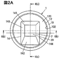
- FIG. 2A is a front view for explaining a positional relationship between a reading surface and a guide recess of the switch device according to the embodiment.
- FIG. 2B is a cross-sectional view taken along the line II (b) -II (b) of FIG. 2A as viewed from the direction of the arrow.
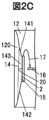
- FIG. 2C is a cross-sectional view taken along the line II (c) -II (c) of FIG. 2A as viewed from the direction of the arrow.
- FIG. 2D is a front view showing a guide recess of the switch device according to the modification.
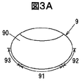
- FIG. 3A is a front view of the operation finger.
- FIG. 3B is a side view of the operation finger.
- FIG. 3C is an explanatory diagram illustrating a read image read by the switch device according to the embodiment
- the switch device includes an operation button having an operation surface on which a push operation is performed, a guide recess provided on the operation surface, having a slender shape surrounded by an inclined surface, and guiding an operation finger, A reading surface for reading the biological information of the operating finger to be read, and a biological information sensor whose reading surface is exposed from the center in the longitudinal direction of the guide recess toward the end surface.
- the reading surface is arranged closer to the end face side from the center in the longitudinal direction of the guide concave portion, so that compared with the case where this configuration is not adopted, the contact of the operating finger is good, and the guide property is high, Operability is good.
- FIG. 1A is a front view illustrating the switch device according to the embodiment
- FIG. 1B is a block diagram illustrating the switch device according to the embodiment.
- FIG. 2A is a front view for explaining the positional relationship between the reading surface and the guide recess of the switch device according to the embodiment, and FIG. 2B is cut along the line II (b) -II (b) in FIG. 2A.
- FIG. 2C is a cross-sectional view of the cross section taken along line II (c) -II (c) of FIG. 2A as viewed from the direction of the arrow, and FIG. It is a front view showing the guide crevice of the switch device concerning an example.
- 3A is a front view of the operation finger
- FIG. 3B is a side view of the operation finger
- FIG. 3C is an explanatory diagram illustrating a read image read by the switch device according to the embodiment.
- FIG. 1B the flow of main signals and information is indicated by arrows.
- the switch device 1 is disposed, for example, on a panel in front of a user sitting in a driver's seat, a steering wheel, a floor console located between a driver's seat and a passenger seat, and the like. Therefore, when the guide concave portion 14 of the present embodiment is disposed on, for example, a panel or a steering wheel in front of the user, the upper and lower sides of the paper of FIG. 1A coincide with the upper and lower sides of the vehicle, so the first inclined surface 141 is on the upper side.
- the second inclined surface 142 is on the lower side. Further, when the guide recess 14 is disposed at a location substantially parallel to the floor of the vehicle such as a floor console, for example, the second inclined surface 142 on the paper surface of FIG.
- 1A is on the user side.
- the guide concave portion 14 when the guide concave portion 14 is located with respect to the operation finger 9, the guideability is reduced, so that the reading surface 20 is provided on the third inclined surface 143 or the fourth inclined surface 144 side. Is not placed.
- the switch device 1 instructs the vehicle to start or prepare to start the driving device of the vehicle when the authentication of the biometric information 23 accompanying the push operation (ON operation) is completed, and the push operation (OFF operation) performed thereafter.
- the driving device is configured to be instructed to stop. Note that the instruction to stop the driving device is issued without authentication of the biological information 23.
- the drive device is an internal combustion engine (engine)
- the engine is started by a push operation performed in a state where the operation conditions of the shift device and the brake device are satisfied.
- the drive device is a motor
- a preparation for starting to supply current to the motor is performed by a push operation performed in a state where the above operation conditions are satisfied.
- the driving device is a hybrid of the engine and the motor
- the starting operation or the start preparation is performed by the push operation performed in a state where the above-mentioned operating conditions are satisfied, in accordance with the driving device which is prioritized at the time of starting.
- the stop operation of the drive device is instructed by the off operation performed after the on operation.
- the switch device 1 has, for example, as shown in FIGS. 1A and 1B, an operation button 12 having an operation surface 120 on which a push operation is performed, and an elongated shape provided on the operation surface 120 and surrounded by an inclined surface. And a reading surface 20 for reading the biological information 23 of the operating finger 9 in contact therewith.
- the reading surface 20 extends from the center in the longitudinal direction of the guide recess 14 to the end surface (the first inclined surface).
- the biological information sensor 2 that is exposed toward the surface 141 or the second inclined surface 142).
- the switch device 1 is disposed on the substrate 16 as shown in FIGS. 1B, 2B, and 2C, for example, and the registered biometric information 40 registered in advance by the registrant and the biometric information of the user read by the biometric information sensor 2.
- the control unit 4 is provided as an authentication unit for performing authentication as to whether or not the user is a registrant by comparing with the user 23.
- the switch device 1 includes, for example, a cylindrical main body 10.
- the operation button 12 is inserted into the opening 102 of the main body 10.
- the switch device 1 includes a switch unit 3 that detects that the operation button 12 is pushed into the main body 10 by a push operation.
- the above-described substrate 16 is, for example, a printed wiring board.
- the control unit 4 is electrically connected to the biological information sensor 2 via a flexible board 17, for example, as shown in FIGS. 2B and 2C.
- the board 16 is attached to, for example, the operation button 12 and is configured to move integrally with the operation button 12 with a push operation.
- the biological information sensor 2 is, for example, a capacitance-type sensor. As shown in FIG. 1A, for example, as shown in FIG. 1A, the biometric information sensor 2 is configured to read the biometric information 23 from the operation finger 9 in contact with the reading surface 20 when operating the operation button 12 of the switch device 1.
- the biometric information 23 is, for example, a fingerprint of the operation finger 9, but is not limited thereto, and may be a vein of the operation finger 9.
- the biological information sensor 2 may be, for example, a sensor configured to read a fingerprint of a pressure-sensitive type, a thermal type, or the like.
- the biological information sensor 2 may be configured to read the vein of the operation finger 9 as the biological information 23, for example.
- the reading of the veins is performed using, for example, a sensor configured to read the vein pattern based on the reflection of the irradiated near infrared rays.
- the biological information sensor 2 may be, for example, a sensor combining these.
- a step 15 is provided between the reading surface 20 of the biological information sensor 2 and the guide recess 14, for example, as shown in FIGS. 2B and 2C.
- the step 15 is provided so that the position between the operation finger 9 guided by the guide recess 14 and the reading surface 20 is easily determined, and contributes to the guideability of the operation finger 9.
- the biological information sensor 2 includes, for example, a plurality of detection electrodes arranged in rows and columns in a grid below the reading surface 20.
- the plurality of detection electrodes are formed in tens of thousands to hundreds of thousands, and are arranged at intervals of several ⁇ m to several tens ⁇ m.
- the biological information sensor 2 scans all the detection electrodes by repeatedly reading, for example, the capacitance of the detection electrodes arranged in a row while changing columns, and subsequently reading the capacitance of the detection electrodes by changing rows. Is configured.
- the cycle of this scanning is, for example, about 100 ms.
- the biological information sensor 2 outputs a read image 22 formed based on, for example, a plurality of capacitances read by scanning to the control unit 4.
- the read image 22 is formed based on, for example, the capacitance of one cycle.
- the biological information sensor 2 divides the capacitance above a predetermined threshold value into “1”, the capacitance below the threshold value into “0”, and the position of the detection electrode. And a read image 22 is generated in association with.
- the position of the above-described “1” detection electrode is black, and the position of the “0” detection electrode is white. It should be noted that the circles in the figure are added to indicate a part of feature points 5 described later.
- the capacitance Since the position where the capacitance is high is the position of the peak of the fingerprint and the distance to the detection electrode is short, the capacitance becomes high. The lower position is the position of the valley of the fingerprint, the distance to the detection electrode is longer, and the capacitance is lower. Therefore, if the position where the capacitance is high is black and the position where the capacitance is low is white, a read image 22 as shown in FIG. 3C is obtained as an example. The image shown in black in the read image 22 is the read biological information 23.
- This biometric information 23 is preferably, for example, a fingerprint of the belly region 91 of the operation finger 9 shown in FIGS. 3A and 3B. This is because, for example, the antinode region 91 includes many feature points 5 such as a center point described later shown in FIG. 3C. Therefore, even when the user performs a push operation without gazing at the operation button 12, the guide concave portion 14 and the step portion 15 guide the abdomen region 91 and the reading surface 20 so as to be in contact with each other.
- the switch unit 3 is configured as, for example, a rubber dome switch that contacts an end of the operation button 12 opposite to the operation surface 120.
- the rubber dome switch includes, for example, a rubber dome that generates an elastic force and has a movable contact, and a switch board on which the rubber dome is arranged and has a fixed contact facing the movable contact.
- the movable contact When the operation button 12 by the push operation is pushed into the main body 10, the movable contact is electrically connected to the fixed contacts by deformation of rubber dome switch signals S 1 indicating that the switch is turned on is output to the control unit 4.
- the switch device 1 is configured such that, for example, when the push operation ends, the operation button 12 returns to the initial position by the elastic force of the rubber dome.
- the control unit 4 includes, for example, a CPU (Central Processing Unit) that performs operations, processing, and the like on the acquired data according to a stored program, a RAM (Random Access Memory) that is a semiconductor memory, a ROM (Read Only Memory), and the like. Microcomputer. In the ROM, for example, a program for operating the control unit 4 is stored.
- the RAM stores, for example, the registered biometric information 40 and the similarity threshold 41, and is used as a storage area for storing the acquired registered biometric information 40, the calculation result, and the like.
- the control unit 4 stores, for example, the registered biometric information 40 for each user and the registered biometric information 40 registered with a plurality of operating fingers of the user.
- control unit 4 performs an extraction process on the read image 22 to extract the feature points 5.
- This extraction processing is, for example, ridge extraction processing.
- the feature point 5 is, for example, a center point, a branch point, an end point, and a delta as shown in FIG. 3C, but is not limited thereto.
- the center point is a point that is the center of the fingerprint.
- the branch point is a point at which the ridge of the fingerprint branches.
- An end point is a point where a ridge is broken.
- Deltas are points where ridges gather from three directions.
- the control unit 4 extracts the feature point 5 from the read image 22, for example. Then, for example, the control unit 4 compares the acquired registered biometric information 40 with the biometric information 23 from which the feature points 5 are extracted, and determines the similarity based on the position of the feature points 5, the distance between the feature points 5, and the like. Is calculated. The control unit 4, the degree of similarity may was similarity threshold 41 or more, and outputs the authentication information S 2 as the authentication of the biological information 23 is satisfied.
- the similarity threshold 41 is, for example, 80%. That is, for example, when the number of the feature points 5 of the biometric information 23 used for authentication is 80, the control unit 4 Is determined to be a registrant. Note that the match includes matching such as the position of the feature point 5 and the distance between the feature points 5.
- the control unit 4 for example, the switch unit 3 is turned on based on the switch signal S 1, that is with determining the push operation is performed, if the authentication of the biological information 23 is satisfied, authentication indicating that the authentication is successful outputs information S 2 to the vehicle-mounted device that is electromagnetically connected.
- the vehicle unit executes, for example, setting the user authentication is successful based on the authentication information S 2 is registered.
- the in-vehicle device is a seat driving device
- the seat is driven to the seat position registered by the user.
- the in-vehicle device is an air conditioner
- the setting such as the set temperature and the air volume registered by the user is performed.
- the vehicle-mounted device is a mirror driving device
- the mirror is driven to a position registered by the user.
- the electromagnetic connection is, for example, a connection using at least one of a connection via a conductor, a connection via light which is a kind of electromagnetic wave, and a connection via a radio wave which is a kind of electromagnetic wave.
- the operation button 12 has a concave shape on the operation surface 120 as shown in FIGS. 2A to 2C, for example, but is not limited thereto.
- the reading surface 20 of the biological information sensor 2 is disposed, for example, at the center of the operation surface 120 as shown in FIG. 2A.
- the dotted line illustrated in FIG. 2A is a straight line that passes through the center of the circular operation surface 120 and is orthogonal to the operation surface 120.
- 2A is a straight line passing through the center of the guide recess 14 in the longitudinal direction.
- the reading surface 20 is arranged so that the center is on the first inclined surface 141 side from the one-dot chain line and coincides with the intersection of the dotted lines.
- the reading surface 20 is exposed at the bottom of the concave shape because the operation surface 120 has a concave shape.
- the guide recess 14 is inclined from the operation surface 120 toward the reading surface 20 and is opposed to the first inclined surface 141 that faces through the reading surface 20. It has a second inclined surface 142, a third inclined surface 143, and a fourth inclined surface 144, and the first inclined surface 141 or the second inclined surface 142 contacts the distal end region 90 of the operation finger 9,
- the third inclined surface 143 and the fourth inclined surface 144 are in contact with the two side regions (the left side region 92 and the left side region 93) of the operation finger 9.
- the second inclined surface 142 extends below the operation surface 120, so that the edge of the guide concave portion 14 is read. It is inclined with respect to the plane 20.
- the tip of the operation finger 9 is attached to the first inclined surface 141.
- the area 90 contacts.
- the left side area 92 of the operation finger 9 contacts the third inclined surface 143 and the right side area 93 contacts the fourth inclined surface 144.
- the abdomen rear end area 94 behind the abdomen area 91 of the operation finger 9 shown in FIG. 3B contacts, for example, the second inclined surface 142.
- the operation finger 9 is guided and faces the reading surface 20 while the abdomen region 91 is fitted to the step portion 15.
- the distal end region 90 of the operation finger 9 contacts the inclined surface corresponding to the first inclined surface 141, and the abdominal rear end region 94 is the second inclined region.
- the contact with the inclined surface 142 corresponds to the inclined surface 142 and the contact is made in a narrow range.
- the second inclined surface 142 of the present embodiment has a smaller inclination angle than the other inclined surfaces, that is, a gentler angle, the stimulation to the operation finger 9 is small, and even if the abdomen rear end region 94 comes into contact, an uncomfortable feeling is generated. hard.
- the second inclined surface 142 has a small inclination angle, it is difficult for the second inclined surface 142 to function as a stopper for stopping the sliding of the operation finger 9. There is a possibility that the position with 20 is shifted.
- the switch device 1 of the present embodiment since the step portion 15 is formed, the user can easily recognize the position of the reading surface 20 by fitting the abdomen region 91 to the step portion 15, and the step portion 15 is operated. The sliding of the finger 9 is suppressed, and the abdomen area 91 and the reading surface 20 are positioned.
- the switch device 1 can easily determine the positions of the abdominal region 91 of the operating finger 9 and the reading surface 20 where the user wants to read the biometric information 23 even when the user operates the operating button 12 without gazing. 9 prevents a sense of incongruity caused by contact with the guide recess 14.
- the guide recess 14 may be provided such that the reading surface 20 is located on the second inclined surface 142 side, as shown in FIG. 2D.
- the tip region 90 and the abdomen region 91 of the operation finger 9 come into contact with the first inclined surface 141 having a small inclination angle, so that the finger touch is good.
- the step portion 15 and the second inclined surface 142 serve as stoppers, so that the positioning between the abdominal region 91 and the reading surface 20 becomes easy, and the guide is provided. High.
- the switch device 1 of the present embodiment has good operability. Specifically, in the switch device 1, the reading surface 20 is positioned on the first inclined surface 141 side of the guide concave portion 14, so that the inclination angle of the second inclined surface 142 becomes gentler than other inclined surfaces. Therefore, as compared with the case having the same inclination angle, the finger touch is better, the guide property is higher, and the operability is better.
- the position of the reading surface 20 is easily recognized by the user by the step portion 15, and therefore, the guide property is higher than that in a case where this configuration is not adopted.
- the switch device 1 Since the switch device 1 has high guideability by the guide concave portion 14 and the step portion 15, the operation finger 9 is guided to an appropriate position without the user gazing at the operation button 12, as compared with a case where this configuration is not adopted. be able to.
- the switch device 1 guides the operating finger 9 to an appropriate position by the guide concave portion 14 and the step portion 15, so that the read biometric information 23 can use the characteristic point 5 that can be used for authentication as compared with the case where this configuration is not adopted. Are included, and the accuracy of authentication is improved.
- the operation surface 120 of the switch device 1 Since the operation surface 120 of the switch device 1 has a concave shape, the position of the biological information sensor 2 is easy to understand and guideability is higher than in the case where the operation surface 120 is not concave.
Landscapes
- Engineering & Computer Science (AREA)
- Human Computer Interaction (AREA)
- Physics & Mathematics (AREA)
- General Physics & Mathematics (AREA)
- Theoretical Computer Science (AREA)
- Mechanical Engineering (AREA)
- General Engineering & Computer Science (AREA)
- Multimedia (AREA)
- Combustion & Propulsion (AREA)
- Chemical & Material Sciences (AREA)
- Computer Security & Cryptography (AREA)
- Computer Hardware Design (AREA)
- Software Systems (AREA)
- Measurement Of The Respiration, Hearing Ability, Form, And Blood Characteristics Of Living Organisms (AREA)
- Image Input (AREA)
- Push-Button Switches (AREA)
Abstract
スイッチ装置1は、プッシュ操作がなされる操作面120を有する操作ボタン12と、操作面120に設けられ、傾斜面に囲まれた細長い形状を有して操作指9を案内するガイド凹部14と、接触する操作指9の生体情報23を読み取る読取面20を有し、読取面20がガイド凹部14の長手方向の中央から端面(第1の傾斜面141又は第2の傾斜面142)側に寄って露出する生体情報センサ2と、を有する。
Description
本出願は、2018年7月2日に出願された日本国特許出願2018-125784号の優先権を主張するものであり、日本国特許出願2018-125784号の全内容を本出願に参照により援用する。
本発明は、スイッチ装置に関する。
指紋を読み取る指紋センサの周囲に、ユーザが指紋センサ上に指を載せたとき指と接触するガイド突起又はくぼみを設けた指紋センサ装置が知られている(例えば、特許文献1参照。)。
ユーザは、登録時に感じた指に対するガイド突起の位置を覚えておき、後に指紋認証を行うとき、登録時に覚えた位置と同じ位置にガイド突起がくるように指を指紋センサ上に載せることで、登録時と同じ位置に指を置くことが容易に可能となる。従って指紋センサ装置は、予め登録された指紋画像に対する認証時の指紋画像の位置の誤差を低減させることができる。
特許文献1の指紋センサ装置は、スイッチの操作ボタンに配置した場合、ガイド突起の位置を意識してプッシュ操作を行ったり、ガイド突起が指に接触した状態でプッシュ操作を行ったりするので、煩わしかったり、指に刺激が生じたりして操作性が低下する可能性がある。
本発明の目的は、操作性が良いスイッチ装置を提供することにある。
本発明の一実施形態によるスイッチ装置は、プッシュ操作がなされる操作面を有する操作ボタンと、操作面に設けられ、傾斜面に囲まれた細長い形状を有して操作指を案内するガイド凹部と、接触する操作指の生体情報を読み取る読取面を有し、読取面がガイド凹部の長手方向の中央から端面側に寄って露出する生体情報センサと、を有する。
本発明の一実施形態によれば、操作性が良いスイッチ装置を提供することができる。
(実施の形態の要約)
実施の形態に係るスイッチ装置は、プッシュ操作がなされる操作面を有する操作ボタンと、操作面に設けられ、傾斜面に囲まれた細長い形状を有して操作指を案内するガイド凹部と、接触する操作指の生体情報を読み取る読取面を有し、読取面がガイド凹部の長手方向の中央から端面側に寄って露出する生体情報センサと、を有する。
実施の形態に係るスイッチ装置は、プッシュ操作がなされる操作面を有する操作ボタンと、操作面に設けられ、傾斜面に囲まれた細長い形状を有して操作指を案内するガイド凹部と、接触する操作指の生体情報を読み取る読取面を有し、読取面がガイド凹部の長手方向の中央から端面側に寄って露出する生体情報センサと、を有する。
このスイッチ装置は、読取面がガイド凹部の長手方向の中央から端面側に寄って配置されているので、この構成を採用しない場合と比べて、操作指の指あたりが良く、ガイド性が高く、操作性が良い。
[実施の形態]
(スイッチ装置1の概要)
図1Aは、実施の形態に係るスイッチ装置を示す正面図であり、図1Bは、実施の形態に係るスイッチ装置を示すブロック図である。図2Aは、実施の形態に係るスイッチ装置の読取面とガイド凹部との位置関係を説明するための正面図であり、図2Bは、図2AのII(b)-II(b)線で切断した断面を矢印方向から見た断面図であり、図2Cは、図2AのII(c)-II(c)線で切断した断面を矢印方向から見た断面図であり、図2Dは、変形例に係るスイッチ装置のガイド凹部を示す正面図である。図3Aは、操作指の正面図であり、図3Bは、操作指の側面図であり、図3Cは、実施の形態に係るスイッチ装置が読み取る読取画像を示す説明図である。
(スイッチ装置1の概要)
図1Aは、実施の形態に係るスイッチ装置を示す正面図であり、図1Bは、実施の形態に係るスイッチ装置を示すブロック図である。図2Aは、実施の形態に係るスイッチ装置の読取面とガイド凹部との位置関係を説明するための正面図であり、図2Bは、図2AのII(b)-II(b)線で切断した断面を矢印方向から見た断面図であり、図2Cは、図2AのII(c)-II(c)線で切断した断面を矢印方向から見た断面図であり、図2Dは、変形例に係るスイッチ装置のガイド凹部を示す正面図である。図3Aは、操作指の正面図であり、図3Bは、操作指の側面図であり、図3Cは、実施の形態に係るスイッチ装置が読み取る読取画像を示す説明図である。
なお以下に記載する実施の形態に係る各図において、図形間の比率は、実際の比率とは異なる場合がある。また図1Bでは、主な信号や情報の流れを矢印で示している。
このスイッチ装置1は、例えば、運転席に着座するユーザの前方のパネル、ステアリング、及び運転席と助手席の間に位置するフロアコンソールなどに配置されている。従って本実施の形態のガイド凹部14は、例えば、ユーザの前方のパネルやステアリングに配置される場合、図1Aの紙面上下が車両の上下と一致するので、第1の傾斜面141が上側となり、第2の傾斜面142が下側となる。またガイド凹部14は、例えば、フロアコンソールなど車両の床に略平行な場所に配置されている場合、図1Aの紙面の第2の傾斜面142がユーザ側となる。なお例えば、図1Aに示すように、操作指9に対してガイド凹部14が位置する場合、ガイド性が低下するので、第3の傾斜面143又は第4の傾斜面144側には読取面20が配置されない。
スイッチ装置1は、プッシュ操作(オン操作)に伴う生体情報23の認証の成立により、車両の駆動装置の始動、又は始動準備を車両に指示し、その後になされたプッシュ操作(オフ操作)により、駆動装置の停止を指示するように構成されている。なお駆動装置の停止の指示は、生体情報23の認証を伴わないで行われる。
具体的には、駆動装置が内燃機関(エンジン)である場合、シフト装置やブレーキ装置の操作条件が満足された状態でなされたプッシュ操作によりエンジンが始動する。また駆動装置がモータである場合、上記の操作条件が満足された状態でなされたプッシュ操作によりモータに電流を供給する始動準備が行われる。さらに駆動装置がエンジンとモータのハイブリッドである場合、上記の操作条件が満足された状態でなされたプッシュ操作により、始動時に優先される駆動装置に対応して始動又は始動準備が行われる。このオン操作の後に行われたオフ操作によって、駆動装置の停止が指示される。
このスイッチ装置1は、例えば、図1A及び図1Bに示すように、プッシュ操作がなされる操作面120を有する操作ボタン12と、操作面120に設けられ、傾斜面に囲まれた細長い形状を有して操作指9を案内するガイド凹部14と、接触する操作指9の生体情報23を読み取る読取面20を有し、読取面20がガイド凹部14の長手方向の中央から端面(第1の傾斜面141又は第2の傾斜面142)側に寄って露出する生体情報センサ2と、を有する。
またスイッチ装置1は、例えば、図1B、図2B及び図2Cに示すように、基板16に配置され、登録者によって予め登録された登録生体情報40と生体情報センサ2が読み取ったユーザの生体情報23とを比較して当該ユーザが登録者であるか否かの認証を行う認証部としての制御部4を備えている。
さらにスイッチ装置1は、例えば、円筒形の本体10を備えている。操作ボタン12は、この本体10の開口102に挿入されている。またさらにスイッチ装置1は、プッシュ操作によって操作ボタン12が本体10側に押し込まれたことを検出するスイッチ部3を備えている。
上述の基板16は、例えば、プリント配線基板である。制御部4は、例えば、図2B及び図2Cに示すように、フレキシブル基板17を介して生体情報センサ2と電気的に接続されている。基板16は、例えば、操作ボタン12に取り付けられ、プッシュ操作に伴って操作ボタン12と一体に移動するように構成されている。
(生体情報センサ2の構成)
生体情報センサ2は、一例として、静電容量式のセンサである。この生体情報センサ2は、例えば、図1Aに示すように、スイッチ装置1の操作ボタン12を操作する際、読取面20に接触した操作指9から生体情報23を読み取るように構成されている。
生体情報センサ2は、一例として、静電容量式のセンサである。この生体情報センサ2は、例えば、図1Aに示すように、スイッチ装置1の操作ボタン12を操作する際、読取面20に接触した操作指9から生体情報23を読み取るように構成されている。
生体情報23は、例えば、操作指9の指紋であるがこれに限定されず、操作指9の静脈であっても良い。
なお変形例として生体情報センサ2は、例えば、感圧式、感熱式などの指紋を読み取るように構成されたセンサであっても良い。また生体情報センサ2は、例えば、生体情報23として操作指9の静脈を読み取るように構成されても良い。静脈の読み取りは、例えば、照射した近赤外線の反射に基づいて静脈パターンを読み取るように構成されたセンサを用いて行われる。そして生体情報センサ2は、例えば、これらを組み合わせたセンサであっても良い。
生体情報センサ2の読取面20とガイド凹部14との間には、例えば、図2B及び図2Cに示すように、段差部15が設けられている。この段差部15は、ガイド凹部14に案内された操作指9と読取面20との位置が決まり易いように設けられ、操作指9のガイド性に貢献している。
生体情報センサ2は、例えば、読取面20の下方に、格子状に行と列に並ぶ複数の検出電極を備えている。この複数の検出電極は、一例として、数万から数十万個形成されると共に、数μmから数十μmの間隔で配置されている。
生体情報センサ2は、例えば、列を替えながら行に並ぶ検出電極の静電容量を読み出し、続いて行を替えて検出電極の静電容量を読み出すことを繰り返して全ての検出電極を走査するように構成されている。この走査の周期は、一例として、100ms程度である。
生体情報センサ2は、例えば、走査して読み出した複数の静電容量に基づいて形成される読取画像22を制御部4に出力する。この読取画像22は、例えば、1周期分の静電容量に基づいて形成される。
具体的には、生体情報センサ2は、例えば、予め設けられたしきい値以上の静電容量を「1」、しきい値より低い静電容量を「0」に分けると共に、検出電極の位置と関連付けて読取画像22を生成する。
図3Cに示す読取画像22は、一例として、上述の「1」の検出電極の位置を黒、「0」の検出電極の位置を白としている。なお図中の丸は、後述する特徴点5の一部を示すために付したものである。
静電容量が高い位置は、指紋の山の位置であって検出電極までの距離が近いので、静電容量が高くなる。そして低い位置は、指紋の谷の位置であって検出電極までの距離が遠く、静電容量が低くなる。従って静電容量の高い位置を黒、低い位置を白とすると、一例として、図3Cに示すような読取画像22が得られる。この読取画像22において黒で示した画像は、読み取られた生体情報23である。
この生体情報23は、例えば、図3A及び図3Bに示す操作指9の腹領域91の指紋であることが好ましい。この腹領域91は、例えば、図3Cに示す、後述する中心点などの特徴点5を多く含むからである。従ってガイド凹部14及び段差部15は、ユーザが操作ボタン12を注視することなくプッシュ操作を行ったとしても、腹領域91と読取面20とが接触するように案内する。
(スイッチ部3の構成)
スイッチ部3は、例えば、操作ボタン12の操作面120とは反対側となる端部と接触するラバードームスイッチとして構成されている。このラバードームスイッチは、例えば、弾性力を生成すると共に可動接点を有するラバードームと、ラバードームが配置され、可動接点と対向する固定接点を有するスイッチ基板と、を備えている。
スイッチ部3は、例えば、操作ボタン12の操作面120とは反対側となる端部と接触するラバードームスイッチとして構成されている。このラバードームスイッチは、例えば、弾性力を生成すると共に可動接点を有するラバードームと、ラバードームが配置され、可動接点と対向する固定接点を有するスイッチ基板と、を備えている。
そしてプッシュ操作によって操作ボタン12が本体10に押し込まれると、ラバードームが変形して可動接点が固定接点と導通し、スイッチがオンしたことを示すスイッチ信号S1が制御部4に出力される。そしてスイッチ装置1は、例えば、プッシュ操作が終了すると、ラバードームの弾性力によって操作ボタン12が初期の位置に復帰するように構成されている。
(制御部4の構成)
制御部4は、例えば、記憶されたプログラムに従って、取得したデータに演算、加工などを行うCPU(Central Processing Unit)、半導体メモリであるRAM(Random Access Memory)及びROM(Read Only Memory)などから構成されるマイクロコンピュータである。このROMには、例えば、制御部4が動作するためのプログラムが格納されている。RAMは、例えば、登録生体情報40と類似度しきい値41を記憶すると共に、取得した登録生体情報40や演算結果などを格納する記憶領域として用いられる。なお制御部4は、例えば、ユーザごとに登録生体情報40を記憶すると共に、ユーザの複数の操作指で登録された登録生体情報40を記憶する。
制御部4は、例えば、記憶されたプログラムに従って、取得したデータに演算、加工などを行うCPU(Central Processing Unit)、半導体メモリであるRAM(Random Access Memory)及びROM(Read Only Memory)などから構成されるマイクロコンピュータである。このROMには、例えば、制御部4が動作するためのプログラムが格納されている。RAMは、例えば、登録生体情報40と類似度しきい値41を記憶すると共に、取得した登録生体情報40や演算結果などを格納する記憶領域として用いられる。なお制御部4は、例えば、ユーザごとに登録生体情報40を記憶すると共に、ユーザの複数の操作指で登録された登録生体情報40を記憶する。
制御部4は、例えば、読取画像22に対して抽出処理を行って特徴点5を抽出する。この抽出処理は、例えば、隆線の抽出処理などである。
特徴点5とは、例えば、図3Cに示すように、中心点、分岐点、端点及び三角州などであるがこれに限定されない。中心点とは、指紋の中心となる点である。分岐点とは、指紋の隆線が分岐している点である。端点とは、隆線が切れている点である。三角州とは、三方向から隆線が集まった点である。
制御部4は、例えば、読取画像22から特徴点5を抽出する。そして制御部4は、例えば、取得した登録生体情報40と、特徴点5が抽出された生体情報23と、を比較し、特徴点5の位置、特徴点5間の距離などに基づいて類似度を算出する。そして制御部4は、類似度が類似度しきい値41以上であった場合、生体情報23の認証が成立したとして認証情報S2を出力する。
この類似度しきい値41は、一例として、80%である。つまり制御部4は、例えば、認証に使用する生体情報23の特徴点5の数が80個である場合、64個以上の特徴点5が登録生体情報40の特徴点5と一致すれば、ユーザが登録者であると判定する。なお一致とは、特徴点5の位置、特徴点5間の距離などの一致を含んでいる。
制御部4は、例えば、スイッチ信号S1に基づいてスイッチ部3がオンされた、つまりプッシュ操作がなされたと判定すると共に、生体情報23の認証が成立した場合、認証が成立したことを示す認証情報S2を電磁気的に接続された車載装置に出力する。この車載装置は、例えば、この認証情報S2に基づいて認証が成立したユーザが登録した設定を実行する。例えば、車載装置がシートの駆動装置であった場合、ユーザが登録したシート位置にシートを駆動する。また例えば、車載装置が空調装置であった場合、ユーザが登録した設定温度、風量などの設定を行う。さらに例えば、車載装置がミラーの駆動装置であった場合、ユーザが登録した位置にミラーを駆動する。なお電磁気的に接続とは、例えば、導電体を介した接続、電磁波の一種である光を介した接続、及び電磁波の一種である電波を介した接続の少なくとも1つを用いた接続である。
(ガイド凹部14の構成)
操作ボタン12は、例えば、図2A~図2Cに示すように、操作面120が凹形状を有しているがこれに限定されない。そして生体情報センサ2の読取面20は、例えば、図2Aに示すように、操作面120の中央に配置されている。
操作ボタン12は、例えば、図2A~図2Cに示すように、操作面120が凹形状を有しているがこれに限定されない。そして生体情報センサ2の読取面20は、例えば、図2Aに示すように、操作面120の中央に配置されている。
図2Aに示す点線は、円形状を有する操作面120の中央を通ると共に直交する直線である。また図2Aに示す一点鎖線は、ガイド凹部14の長手方向の中心を通る直線である。読取面20は、中心が一点鎖線から第1の傾斜面141側であり、かつ点線の交点と一致するように配置されている。また読取面20は、操作面120が凹形状を有しているので、凹形状の底に露出している。
そしてガイド凹部14は、例えば、図2A~図3Bに示すように、傾斜面として、操作面120から読取面20に向かって傾斜すると共に読取面20を介して対向する第1の傾斜面141と第2の傾斜面142、及び第3の傾斜面143と第4の傾斜面144を有し、第1の傾斜面141又は第2の傾斜面142が操作指9の先端領域90に接触し、第3の傾斜面143及び第4の傾斜面144が操作指9の2つの側面領域(左側面領域92及び左側面領域93)に接触する。
このガイド凹部14は、例えば、図2Cに示すように、操作面120が凹面である場合、第2の傾斜面142が操作面120の下側に伸びているので、ガイド凹部14の縁が読取面20に対して傾いている。
読取面20が第1の傾斜面141側に位置する場合、例えば、図2A~図2Cに示すように、ユーザがプッシュ操作を行うと、第1の傾斜面141には、操作指9の先端領域90が接触する。そして操作指9の左側面領域92が第3の傾斜面143に接触すると共に右側面領域93が第4の傾斜面144に接触する。また図3Bに示す操作指9の腹領域91の後方となる腹後端領域94は、例えば、第2の傾斜面142と接触する。
この第1の傾斜面141~第4の傾斜面144との接触により、操作指9は、案内されて腹領域91が段差部15に嵌りつつ読取面20と対向する。ここで、例えば、ガイド凹部14の外形が細長くなく正方形に近い場合、操作指9の先端領域90が第1の傾斜面141に相当する傾斜面に接触すると共に、腹後端領域94が第2の傾斜面142に相当する傾斜面に接触して狭い範囲で接触することになるので、操作指9に対する刺激から違和感が生じる可能性がある。しかし本実施の形態の第2の傾斜面142は、傾斜角が他の傾斜面よりも小さい、つまり緩やかなので、操作指9に対する刺激が小さく、腹後端領域94が接触しても違和感が生じ難い。
そして段差部15が形成されていない場合、第2の傾斜面142の傾斜角が小さいことから、第2の傾斜面142が操作指9の滑りを止めるストッパとなり難いので、腹領域91と読取面20との位置がずれる可能性がある。しかし本実施の形態のスイッチ装置1は、段差部15が形成されているので、腹領域91が段差部15に嵌ることでユーザが読取面20の位置を意識し易く、また段差部15が操作指9の滑りを抑制すると共に腹領域91と読取面20との位置決めとなっている。
従ってスイッチ装置1は、ユーザが操作ボタン12を注視しないで操作する場合であっても生体情報23を読み取らせたい操作指9の腹領域91と読取面20との位置が決まり易く、また操作指9がガイド凹部14に接触することによる違和感を抑制する。
ここで変形例としてガイド凹部14は、例えば、図2Dに示すように、第2の傾斜面142側に読取面20が位置するように設けられても良い。この場合、ユーザは、プッシュ操作の際、例えば、操作指9の先端領域90や腹領域91などが傾斜角の小さい第1の傾斜面141に接触するので、指あたりが良い。また例えば、プッシュ操作によって操作指9が第1の傾斜面141を移動した場合、段差部15及び第2の傾斜面142がストッパとなり、腹領域91と読取面20との位置決めが容易となり、ガイド性が高い。
(実施の形態の効果)
本実施の形態のスイッチ装置1は、操作性が良い。具体的には、スイッチ装置1は、ガイド凹部14の第1の傾斜面141側に読取面20が位置することで、第2の傾斜面142の傾斜角が他の傾斜面よりも緩やかになるので、同じ傾斜角を有する場合と比べて、指あたりが良くてガイド性が高く、操作性が良い。
本実施の形態のスイッチ装置1は、操作性が良い。具体的には、スイッチ装置1は、ガイド凹部14の第1の傾斜面141側に読取面20が位置することで、第2の傾斜面142の傾斜角が他の傾斜面よりも緩やかになるので、同じ傾斜角を有する場合と比べて、指あたりが良くてガイド性が高く、操作性が良い。
スイッチ装置1は、段差部15によって読取面20の位置がユーザにとって認識し易くなっているので、この構成を採用しない場合と比べて、ガイド性が高い。
スイッチ装置1は、ガイド凹部14及び段差部15によってガイド性が高いので、この構成を採用しない場合と比べて、ユーザが操作ボタン12を注視しなくても適切な位置に操作指9を案内することができる。
スイッチ装置1は、ガイド凹部14及び段差部15によって操作指9を適切な位置に案内するので、この構成を採用しない場合と比べて、読み取られた生体情報23に認証に使用可能な特徴点5が多く含まれ、認証の精度が向上する。
スイッチ装置1は、操作面120が凹形状を有しているので、凹形状でない場合と比べて、生体情報センサ2の位置の分かり易さやガイド性が高い。
以上、本発明のいくつかの実施の形態及び変形例を説明したが、これらの実施の形態及び変形例は、一例に過ぎず、請求の範囲に係る発明を限定するものではない。これら新規な実施の形態及び変形例は、その他の様々な形態で実施されることが可能であり、本発明の要旨を逸脱しない範囲で、種々の省略、置き換え、変更などを行うことができる。また、これら実施の形態及び変形例の中で説明した特徴の組合せの全てが発明の課題を解決するための手段に必須であるとは限らない。さらに、これら実施の形態及び変形例は、発明の範囲及び要旨に含まれると共に、請求の範囲に記載された発明とその均等の範囲に含まれる。
1 スイッチ装置
2 生体情報センサ
9 操作指
12 操作ボタン
14 ガイド凹部
15 段差部
20 読取面
90 先端領域
91 腹領域
92 左側面領域
93 右側面領域
94 腹後端領域
120 操作面
141 第1の傾斜面
142 第2の傾斜面
143 第3の傾斜面
144 第4の傾斜面
2 生体情報センサ
9 操作指
12 操作ボタン
14 ガイド凹部
15 段差部
20 読取面
90 先端領域
91 腹領域
92 左側面領域
93 右側面領域
94 腹後端領域
120 操作面
141 第1の傾斜面
142 第2の傾斜面
143 第3の傾斜面
144 第4の傾斜面
Claims (10)
- プッシュ操作がなされる操作面を有する操作ボタンと、
前記操作面に設けられ、傾斜面に囲まれた細長い形状を有して操作指を案内するガイド凹部と、
接触する操作指の生体情報を読み取る読取面を有し、前記読取面が前記ガイド凹部の長手方向の中央から端面側に寄って露出する生体情報センサと、
を備えたスイッチ装置。 - 前記操作ボタンは、前記操作面が凹形状を有する、
請求項1に記載のスイッチ装置。 - 前記読取面は、前記操作面の前記凹形状の底に配置される、
請求項2に記載のスイッチ装置。 - 前記読取面は、前記操作面の中央に配置される、
請求項1乃至3のいずれか1項に記載のスイッチ装置。 - 前記ガイド凹部は、前記端面より前記端面と反対側の端面が前記読取面に対する高さが大になっていることにより、前記端面の縁が前記読取面に対して傾いている、
請求項1乃至4のいずれか1項に記載のスイッチ装置。 - 前記読取面と前記ガイド凹部との間には、段差が設けられている、
請求項1乃至5のいずれか1項に記載のスイッチ装置。 - 前記ガイド凹部は、前記操作指の腹領域が前記読取面と対向するように前記操作指を案内する、
請求項1乃至6のいずれか1項に記載のスイッチ装置。 - 前記ガイド凹部は、前記傾斜面として、前記操作面から前記読取面に向かって傾斜すると共に前記読取面を介して対向する第1の傾斜面と第2の傾斜面、及び第3の傾斜面と第4の傾斜面を有し、前記第1の傾斜面又は前記第2の傾斜面が前記操作指の先端領域に接触し、前記第3の傾斜面及び前記第4の傾斜面が前記操作指の2つの側面領域に接触する、
請求項1乃至7のいずれか1項に記載のスイッチ装置。 - 前記読取面は、前記端面側として前記第1の傾斜面側に寄っており、
前記第2の傾斜面は、傾斜角が他の傾斜面より小さい、
請求項8に記載のスイッチ装置。 - 前記読取面は、前記端面側として前記第2の傾斜面に寄っており、
前記第1の傾斜面は、傾斜角が他の傾斜面より小さい、
請求項8に記載のスイッチ装置。
Priority Applications (3)
| Application Number | Priority Date | Filing Date | Title |
|---|---|---|---|
| DE112019003380.8T DE112019003380T5 (de) | 2018-07-02 | 2019-06-25 | Schaltereinrichtung |
| US17/256,835 US20210374446A1 (en) | 2018-07-02 | 2019-06-25 | Switch device |
| CN201980040649.7A CN112313767A (zh) | 2018-07-02 | 2019-06-25 | 开关装置 |
Applications Claiming Priority (2)
| Application Number | Priority Date | Filing Date | Title |
|---|---|---|---|
| JP2018125784A JP2020004314A (ja) | 2018-07-02 | 2018-07-02 | スイッチ装置 |
| JP2018-125784 | 2018-07-02 |
Publications (1)
| Publication Number | Publication Date |
|---|---|
| WO2020008958A1 true WO2020008958A1 (ja) | 2020-01-09 |
Family
ID=69059653
Family Applications (1)
| Application Number | Title | Priority Date | Filing Date |
|---|---|---|---|
| PCT/JP2019/025200 Ceased WO2020008958A1 (ja) | 2018-07-02 | 2019-06-25 | スイッチ装置 |
Country Status (5)
| Country | Link |
|---|---|
| US (1) | US20210374446A1 (ja) |
| JP (1) | JP2020004314A (ja) |
| CN (1) | CN112313767A (ja) |
| DE (1) | DE112019003380T5 (ja) |
| WO (1) | WO2020008958A1 (ja) |
Families Citing this family (3)
| Publication number | Priority date | Publication date | Assignee | Title |
|---|---|---|---|---|
| EP4231867A1 (en) * | 2020-10-23 | 2023-08-30 | JT International SA | Aerosol generating device with biometric identification |
| CN117501264A (zh) * | 2021-07-15 | 2024-02-02 | 因特曼股份有限公司 | 进入控制装置 |
| KR102940849B1 (ko) | 2021-07-15 | 2026-03-19 | 현대자동차주식회사 | 스위치장치 |
Citations (4)
| Publication number | Priority date | Publication date | Assignee | Title |
|---|---|---|---|---|
| JPH03226888A (ja) * | 1990-01-31 | 1991-10-07 | Fujitsu Ltd | 指ガイド |
| JP2002298127A (ja) * | 2001-03-30 | 2002-10-11 | Secom Co Ltd | 指紋照合装置、指紋登録方法及び指紋照合方法 |
| JP2004138416A (ja) * | 2002-10-16 | 2004-05-13 | Nihon Kaiheiki Industry Co Ltd | 感圧式指紋センサー |
| JP2013066995A (ja) * | 2011-09-20 | 2013-04-18 | Samsung Electronics Co Ltd | 触覚伝達装置、システム、及び触覚伝達装置の動作方法 |
Family Cites Families (8)
| Publication number | Priority date | Publication date | Assignee | Title |
|---|---|---|---|---|
| US7146029B2 (en) * | 2003-02-28 | 2006-12-05 | Fujitsu Limited | Chip carrier for fingerprint sensor |
| US7929736B2 (en) * | 2004-11-03 | 2011-04-19 | Pen-One, Inc. | Finger guide device for use with stylus or pen |
| US20060093192A1 (en) * | 2004-11-03 | 2006-05-04 | Bechtel J S | Finger guide device |
| JP4740743B2 (ja) * | 2006-01-06 | 2011-08-03 | 富士通株式会社 | 生体情報入力装置 |
| US9030440B2 (en) * | 2012-05-18 | 2015-05-12 | Apple Inc. | Capacitive sensor packaging |
| US9135494B2 (en) * | 2013-09-09 | 2015-09-15 | Apple Inc. | Finger biometric sensor for flagging as sufficient enrollment finger biometric data sets and related methods |
| JP6534586B2 (ja) * | 2015-09-09 | 2019-06-26 | 株式会社東海理化電機製作所 | 判定装置 |
| KR102583890B1 (ko) * | 2016-02-18 | 2023-10-05 | 삼성전자주식회사 | 열 수집/확산 구조를 가진 전자 장치 |
-
2018
- 2018-07-02 JP JP2018125784A patent/JP2020004314A/ja active Pending
-
2019
- 2019-06-25 US US17/256,835 patent/US20210374446A1/en not_active Abandoned
- 2019-06-25 DE DE112019003380.8T patent/DE112019003380T5/de not_active Withdrawn
- 2019-06-25 WO PCT/JP2019/025200 patent/WO2020008958A1/ja not_active Ceased
- 2019-06-25 CN CN201980040649.7A patent/CN112313767A/zh active Pending
Patent Citations (4)
| Publication number | Priority date | Publication date | Assignee | Title |
|---|---|---|---|---|
| JPH03226888A (ja) * | 1990-01-31 | 1991-10-07 | Fujitsu Ltd | 指ガイド |
| JP2002298127A (ja) * | 2001-03-30 | 2002-10-11 | Secom Co Ltd | 指紋照合装置、指紋登録方法及び指紋照合方法 |
| JP2004138416A (ja) * | 2002-10-16 | 2004-05-13 | Nihon Kaiheiki Industry Co Ltd | 感圧式指紋センサー |
| JP2013066995A (ja) * | 2011-09-20 | 2013-04-18 | Samsung Electronics Co Ltd | 触覚伝達装置、システム、及び触覚伝達装置の動作方法 |
Also Published As
| Publication number | Publication date |
|---|---|
| JP2020004314A (ja) | 2020-01-09 |
| DE112019003380T5 (de) | 2021-04-01 |
| CN112313767A (zh) | 2021-02-02 |
| US20210374446A1 (en) | 2021-12-02 |
Similar Documents
| Publication | Publication Date | Title |
|---|---|---|
| JP2020004314A (ja) | スイッチ装置 | |
| CN107958203B (zh) | 具有方向盘和附装于方向盘上的指纹传感器的人机界面 | |
| JP2022191429A (ja) | 車両 | |
| JP2002193111A (ja) | ステアリング装置及び車両 | |
| JP6494109B2 (ja) | 判定装置 | |
| JP6899798B2 (ja) | 生体情報認証装置 | |
| JP2019071219A (ja) | スイッチ装置 | |
| US11995163B2 (en) | Biometric information authentication device | |
| WO2020027287A1 (ja) | 生体情報認証装置 | |
| CN111052285A (zh) | 开关装置 | |
| JP2020038491A (ja) | 生体情報認証装置 | |
| JP6534587B2 (ja) | 判定装置 | |
| WO2019240085A1 (ja) | スイッチ装置 | |
| JP6694467B2 (ja) | スタートスイッチ装置 | |
| JP7121524B2 (ja) | スタートスイッチ装置 | |
| JP2023183868A (ja) | レバースイッチ、車両用表示制御システム及び車両 | |
| JP6886429B2 (ja) | 生体情報センサ装置 | |
| CN112567424B (zh) | 生物信息认证装置和生物信息认证系统 | |
| JP2019091341A (ja) | 生体情報照合装置及び生体情報認証方法 | |
| WO2019221129A1 (ja) | 生体情報センサ装置及び生体情報の登録方法 |
Legal Events
| Date | Code | Title | Description |
|---|---|---|---|
| 121 | Ep: the epo has been informed by wipo that ep was designated in this application |
Ref document number: 19830866 Country of ref document: EP Kind code of ref document: A1 |
|
| 122 | Ep: pct application non-entry in european phase |
Ref document number: 19830866 Country of ref document: EP Kind code of ref document: A1 |