WO2020008747A1 - スクロール圧縮機 - Google Patents
スクロール圧縮機 Download PDFInfo
- Publication number
- WO2020008747A1 WO2020008747A1 PCT/JP2019/020233 JP2019020233W WO2020008747A1 WO 2020008747 A1 WO2020008747 A1 WO 2020008747A1 JP 2019020233 W JP2019020233 W JP 2019020233W WO 2020008747 A1 WO2020008747 A1 WO 2020008747A1
- Authority
- WO
- WIPO (PCT)
- Prior art keywords
- fixed
- compression chamber
- wrap
- discharge port
- bypass
- Prior art date
- Legal status (The legal status is an assumption and is not a legal conclusion. Google has not performed a legal analysis and makes no representation as to the accuracy of the status listed.)
- Ceased
Links
Images





Classifications
-
- F—MECHANICAL ENGINEERING; LIGHTING; HEATING; WEAPONS; BLASTING
- F04—POSITIVE - DISPLACEMENT MACHINES FOR LIQUIDS; PUMPS FOR LIQUIDS OR ELASTIC FLUIDS
- F04C—ROTARY-PISTON, OR OSCILLATING-PISTON, POSITIVE-DISPLACEMENT MACHINES FOR LIQUIDS; ROTARY-PISTON, OR OSCILLATING-PISTON, POSITIVE-DISPLACEMENT PUMPS
- F04C18/00—Rotary-piston pumps specially adapted for elastic fluids
- F04C18/02—Rotary-piston pumps specially adapted for elastic fluids of arcuate-engagement type, i.e. with circular translatory movement of co-operating members, each member having the same number of teeth or tooth-equivalents
Definitions
- the present disclosure relates to a scroll compressor.
- scroll compressors have been known.
- the scroll compressor is provided, for example, in a refrigerant circuit of a refrigerating apparatus and compresses a refrigerant.
- the compression mechanism of the scroll compressor includes a fixed scroll and an orbiting scroll.
- a plurality of compression chambers are formed by the engagement of the fixed-side wrap of the fixed scroll and the orbiting-side wrap of the orbiting scroll.
- a first compression chamber sandwiched between the outer surface of the turning wrap and the inner surface of the fixed wrap, and a second compression chamber sandwiched between the inner surface of the turning wrap and the outer surface of the fixed wrap. are formed plurally.
- the fluid compressed in each compression chamber is discharged to the outside of the compression mechanism through a discharge port formed at the center of the fixed scroll.
- the conventional scroll compressor has a problem that the pressure loss when the fluid in the second compression chamber flows into the discharge port is larger than the pressure loss when the fluid in the first compression chamber flows into the discharge port. .
- FIG. 11 is a cross-sectional view of the conventional compression mechanism, showing the fixed-side wrap (145) and the revolving-side wrap (165) when the second compression chamber (131B) starts to communicate with the discharge port (143). Show the arrangement. As shown by the dashed arrow in FIG. 11, the fluid in the first compression chamber (131A) smoothly flows into the discharge port (143). On the other hand, as indicated by the solid arrow in FIG. 11, the fluid in the second compression chamber (131B) flows between the end of the fixed wrap (145) and the inner surface (166) of the swivel wrap (165). It flows into the discharge port (143) through a narrow gap. For this reason, the pressure loss when the fluid in the second compression chamber (131B) flows into the discharge port (143) is larger than that in the first compression chamber (131A).
- An object of the present disclosure is to improve the operation efficiency of a scroll compressor.
- a first aspect of the present disclosure is directed to a scroll compressor (10), in which a fixed end plate (41) having a discharge port (43) formed in the center and a front surface (41) of the fixed end plate (41).
- 41a) has a fixed scroll (40) having a spiral wall-shaped fixed side wrap (45) projecting therefrom, and a spiral wall-shaped orbiting side wrap (65), and has a compression mechanism (30) together with the fixed scroll (40).
- the compression mechanism (30) includes an outer side surface (67) of the orbiting side wrap (65) and an inner side surface (46) of the fixed side wrap (45).
- a plurality of first compression chambers (31A) sandwiched therebetween, and a plurality of second compression chambers (31B) sandwiched between an inner surface (66) of the revolving wrap and an outer surface (47) of the fixed wrap are formed.
- fluid is formed in the fixed side end plate part (41) and flows from the second compression chamber (31B) to the outside of the compression mechanism (30).
- the bypass discharge passages (70, 71, 72) that are discharged and the flow of the fluid from the bypass discharge passages (70, 71, 72) to the outside of the compression mechanism (30) are allowed.
- the first compression chamber (31A) closest to the center end (48) of the fixed side wrap (45) starts to communicate with the discharge port (43).
- the opening is formed at a position where it starts to communicate with the second compression chamber (31B) closest to the center side end (48) of the fixed side wrap (45).
- the compression mechanism (30) of the first embodiment when the orbiting scroll (60) orbits, the fluid is compressed in each of the first compression chamber (31A) and the second compression chamber (31B). Then, the fluid in the first compression chamber (31A) and the second compression chamber (31B) is discharged to the outside of the compression mechanism (30) through the discharge port (43). Further, a part of the fluid in the second compression chamber (31B) is discharged to the outside of the compression mechanism (30) through the bypass discharge passages (70, 71, 72).
- both the discharge port (43) and the bypass discharge passages (70, 71, 72) connect the second compression chamber (31B) to the compression mechanism (30). It becomes a passage for leading the fluid to the outside. Therefore, in this aspect, the fluid in the second compression chamber (31B) flows out of the compression mechanism (30) as compared with the conventional scroll compressor without the bypass discharge passages (70, 71, 72). As a result, the degree of overcompression of the fluid in the second compression chamber (31B) is suppressed. Therefore, according to this aspect, the energy consumption of the scroll compressor (10) can be reduced, and the operating efficiency of the scroll compressor (10) can be improved.
- the fixed-side wrap (45) is longer in a circumferential direction than the turning-side wrap (65), and a center of the fixed-side wrap (45).
- the first compression chamber (31A) is located at the center end (48) of the fixed side wrap (45).
- the near second compression chamber (31B) starts to communicate with the discharge port (43).
- the compression mechanism (30) of the second embodiment has a structure in which the circumferential length of the fixed wrap (45) and the circumferential length of the turning wrap (65) are different from each other (a so-called asymmetric spiral structure).
- the first compression chamber (31A) closest to the center end (48) of the fixed wrap (45) is connected to the discharge port (43) during one rotation of the orbiting scroll (60).
- the second compression chamber (31B) closest to the center end (48) of the fixed wrap (45) starts to communicate with the discharge port (43) after the point in time when communication begins.
- the bypass discharge passage (70, 71, 72) in the front surface (41a) of the fixed side end plate portion (41), includes the fixed side wrap ( After the point where the second compression chamber (31B) closest to the center side end (48) of the 45 (45) starts to communicate with the discharge port (43), the center side end (48) of the fixed side wrap (45) starts. ) Is opened at a position where it starts to communicate with the second compression chamber (31B) closest to the second compression chamber (31B).
- the bypass discharge passages (70, 71, 72) open at predetermined positions on the front surface (41a) of the fixed end plate (41).
- the second compression chamber (31B) closest to the center end (48) of the fixed side wrap (45) starts communicating with the discharge port (43) at the same time.
- the communication with the bypass discharge passages (70, 71, 72) starts after the communication with the discharge port (43) starts.
- the fluid is allowed to flow out of the compression mechanism (30) from the discharge port (43) to the outside of the compression mechanism (30).
- the discharge valve (75) doubles as the bypass one-way valve.
- the bypass discharge passages (70, 71, 72) communicate with the discharge port (43).
- the fluid that has flowed into the bypass discharge passages (70, 71, 72) from the second compression chamber (31B) is led out of the compression mechanism (30) through the discharge port (43).
- the discharge valve (75) provided in the scroll compressor (10) also functions as a bypass one-way valve. When the discharge valve (75) allows the fluid to flow from the discharge port (43) to the outside of the compression mechanism (30), the fluid flowing through the bypass discharge passage (70, 71, 72) is discharged to the discharge port (43). After flowing into the compression mechanism (30).
- the cross-sectional shape of the bypass discharge passage (70, 71, 72) is in a direction in which the fixed side wrap (45) extends. It has a long flat shape.
- the cross-sectional shape of the bypass discharge passage (70, 71, 72) is flat. Therefore, the cross-sectional area of the bypass discharge passages (70, 71, 72) can be increased as compared with the case where the cross-sectional shape of the bypass discharge passages (70, 71, 72) is circular. As a result, it is possible to reduce the pressure loss when the fluid passes through the bypass discharge passages (70, 71, 72).
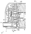
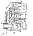
- FIG. 1 is a vertical cross-sectional view of the scroll compressor according to the embodiment.
- FIG. 2 is a longitudinal sectional view of the compression mechanism of the embodiment.
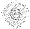
- FIG. 3 is a transverse sectional view of the compression mechanism showing a section taken along line III-III of FIG.
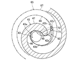
- FIG. 4 is a cross-sectional view of the compression mechanism showing the vicinity of the discharge port in FIG. 3 in an enlarged manner.
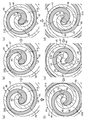
- FIG. 5 is a cross-sectional view corresponding to FIG. 4 and individually showing states of the compression mechanism at a plurality of times during operation of the scroll compressor.
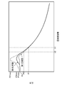
- FIG. 6 is a graph showing the relationship between the volumes of the first compression chamber and the second compression chamber and the refrigerant pressure in the compression mechanism of the embodiment.
- FIG. 7 is a cross-sectional view corresponding to FIG.
- FIG. 4 illustrating a cross-section of a compression mechanism according to a first modification of the embodiment.
- FIG. 8 is a cross-sectional view corresponding to FIG. 4, illustrating a cross-section of a compression mechanism according to a first modification of the embodiment.
- FIG. 9 is a cross-sectional view corresponding to FIG. 4 and illustrating a cross-section of a compression mechanism according to a second modified example of the embodiment.
- FIG. 10 is a cross-sectional view corresponding to FIG. 2 and illustrating a vertical cross-section of a compression mechanism according to a third modification of the embodiment.
- FIG. 11 is a cross-sectional view corresponding to FIG. 4, showing a cross-section of a compression mechanism of a conventional scroll compressor.
- the scroll compressor (10) of the embodiment will be described.
- the scroll compressor (10) is connected to a refrigerant circuit (not shown) in which the refrigerant circulates and performs a refrigeration cycle, and compresses the refrigerant as a fluid.
- the scroll compressor (10) is a hermetic compressor in which a compression mechanism (30) and an electric motor (20) are housed in a casing (11) which is a closed container.
- the casing (11) is a cylindrical pressure vessel with both ends closed.
- the casing (11) is installed so that its axial direction is the up-down direction.
- a suction pipe (12) for introducing the refrigerant of the refrigerant circuit to the compression mechanism (30) is provided.
- the casing (11) is provided with a discharge pipe (13) for leading the refrigerant in the casing (11) out of the casing (11).
- the bottom of the casing (11) stores lubricating oil for lubricating the compression mechanism (30) and the like.
- the electric motor (20) is arranged below the compression mechanism (30).
- the electric motor (20) and the compression mechanism (30) are connected by a drive shaft (25).
- the electric motor (20) includes a stator (21) and a rotor (22).
- the stator (21) of the electric motor (20) is fixed to the casing (11).
- the rotor (22) of the electric motor (20) is attached to the drive shaft (25).
- the drive shaft (25) includes a main shaft (26) and an eccentric shaft (27).
- the axis of the main shaft (26) coincides with the axis of the drive shaft (25).
- the rotor (22) of the electric motor (20) is attached to the main shaft (26).
- an upper portion of the rotor (22) is supported by a bearing portion (36) of a compression mechanism (30) described later, and a lower portion of the rotor (22) is supported by a lower portion described later. It is supported by the bearing member (15).
- the eccentric shaft (27) is formed in a relatively short shaft shape, and protrudes from the upper end of the main shaft (26).
- the axis of the eccentric shaft (27) is substantially parallel to the axis of the main shaft (26) and is eccentric with respect to the axis of the main shaft (26).
- a lower bearing member (15) is provided at a lower portion in the casing (11).
- the lower bearing member (15) is fixed to the casing (11).
- the lower bearing member (15) forms a journal bearing that rotatably supports the main shaft (26) of the drive shaft (25).
- the compression mechanism (30) includes a housing (35), a fixed scroll (40), an orbiting scroll (60), and an Oldham coupling (32).
- the housing (35) is fixed to the casing (11).
- the fixed scroll (40) is arranged on the upper surface of the housing (35).
- the orbiting scroll (60) is arranged between the fixed scroll (40) and the housing (35).
- the housing (35) is a dish-shaped member with a concave center.
- a bearing (36) is formed in the housing (35).
- the bearing portion (36) is a thick cylindrical portion that protrudes downward.
- the bearing (36) forms a journal bearing that rotatably supports the main shaft (26) of the drive shaft (25).
- the fixed scroll (40) includes a fixed-side end plate (41), a fixed-side wrap (45), and an outer peripheral wall (50).
- the fixed side wrap (45) is formed in a spiral wall shape drawing an involute curve (see FIG. 3), and protrudes from the front surface (41a) of the fixed side end plate portion (41).
- the outer peripheral wall portion (50) is formed so as to surround the outer peripheral side of the fixed side wrap (45), and is arranged on the front surface (41a) side of the fixed side end plate portion (41).
- the protruding end face of the fixed wrap (45) and the protruding end face of the outer peripheral wall portion (50) are located substantially on the same plane.
- a suction port (51) is formed in the outer peripheral wall (50) of the fixed scroll (40). The downstream end of the suction pipe (12) is connected to the suction port (51).
- a discharge port (43) that penetrates through the fixed end plate (41) is formed at the center of the fixed end plate (41) of the fixed scroll (40). Further, a bypass discharge passage (70) is formed in the fixed side end plate portion (41). The bypass discharge passage (70) will be described later.
- the discharge port (43) includes a main passage (43a) and an auxiliary passage (43b).
- the main passage portion (43a) is a through hole having a circular cross section.
- the main passage portion (43a) extends in the thickness direction of the fixed-side end plate portion (41) and opens on the back surface (41b) of the fixed-side end plate portion (41).
- the auxiliary passage portion (43b) is a dent opening on the front surface (41a) of the fixed side end plate portion (41).
- the auxiliary passage portion (43b) is formed in a region along the inner side surface (46) of the center end portion (48) of the fixed side wrap (45) in the front surface (41a) of the fixed side end plate portion (41). .
- a high-pressure chamber (55) is formed at the center of the back surface (41b) of the fixed end plate (41).
- the high-pressure chamber (55) is a space that communicates with the discharge port (43).
- the high-pressure chamber (55) communicates with a space below the housing (35) in the casing (11) via a passage (not shown).
- a discharge valve (75) is provided on the back surface (41b) of the fixed end plate (41).
- the discharge valve (75) is a reed valve that opens and closes the discharge port (43).
- the discharge valve (75) allows the refrigerant to flow from the discharge port (43) to the high-pressure chamber (55) and shuts off the refrigerant from flowing from the high-pressure chamber (55) to the discharge port (43).
- the orbiting scroll (60) includes an orbiting end plate (61), an orbiting wrap (65), and a boss (62).
- the turning-side end plate (61) is formed in a substantially circular flat plate shape.
- the turning-side wrap (65) is formed in a spiral wall shape drawing an involute curve (see FIG. 3), and protrudes from the front surface (the upper surface in FIG. 2) of the turning-side end plate portion (61).
- the boss (62) is formed in a cylindrical shape, and is arranged at the center of the rear surface (the lower surface in FIG. 2) of the turning-side end plate (61).
- the eccentric shaft (27) of the drive shaft (25) is inserted into the boss (62).
- a keyway (63) is formed in the orbiting side head (61) of the orbiting scroll (60).
- the key groove (63) is a concave groove that opens on the back surface of the turning-side end plate.
- the key of the Oldham coupling (32) fits into the key groove (63).
- the Oldham coupling (32) is arranged between the orbiting scroll (60) and the housing (35).
- the Oldham coupling (32) engages with each of the orbiting scroll (60) and the housing (35), and regulates rotation of the orbiting scroll (60).
- the inner side surface (46) of the fixed side wrap (45) and the outer side surface (67) of the turning side wrap (65) are in sliding contact with each other at a plurality of locations in the circumferential direction, and come into contact with the outer side surface (47) of the fixed side wrap (45).
- the inner side surface (66) of the turning side wrap (65) is in sliding contact with each other at a plurality of locations in the circumferential direction.
- the protruding end face (lower end face in FIG. 1) of the fixed side wrap (45) is in sliding contact with the front face of the turning side end plate portion (61), and the protruding end face (upper end face in FIG. Slidably contacts the front surface (41a) of the fixed end plate (41).
- a plurality of compression chambers (31A, 31B) surrounded by are formed. Specifically, the first compression chamber (31A) sandwiched between the outer surface (67) of the turning wrap (65) and the inner surface (46) of the fixed wrap (45), and the inner surface ( 66) and a plurality of second compression chambers (31B) sandwiched between the outer side surfaces (47) of the fixed side wraps.
- the compression mechanism (30) has an asymmetric spiral structure in which the circumferential lengths of the fixed side wrap (45) and the turning side wrap (65) are different from each other.
- the circumferential length of the fixed-side wrap (45) is longer than the circumferential length of the turning-side wrap (65).
- the fixed outer wrap (45) has an outermost peripheral portion indicated by a two-dot chain line in FIG. 3 integrated with an outer peripheral wall (50) of the fixed scroll (40).
- the outermost peripheral portion (49) is a portion extending from the middle in the circumferential direction of the fixed side wrap (45) to the outermost peripheral end. That is, the outermost peripheral portion (49) is a portion located closer to the outermost periphery of the fixed side wrap (45). Only the inner surface (46) of the outermost peripheral portion (49) slides on the outer surface (67) of the turning wrap.
- the compression mechanism (30) has an asymmetric spiral structure.
- the corresponding first compression chamber (31A) and the second compression chamber (31B) have different timings when they respectively start communicating with the discharge port (43). Specifically, while the orbiting scroll (60) makes one rotation (ie, while the drive shaft (25) makes one rotation), after the first compression chamber (31A) starts to communicate with the discharge port (43). Then, the second compression chamber (31B) starts to communicate with the discharge port (43).
- the bypass discharge passage (70) is formed in the fixed end plate (41) of the fixed scroll (40).
- the bypass discharge passage is a passage for communicating the second compression chamber (31B) with the discharge port (43) during a predetermined period during one revolution of the orbiting scroll (60).
- the bypass discharge passage (70) is a through hole extending in a direction intersecting the thickness direction of the fixed side end plate (41). As shown in FIG. 3, the bypass discharge passage (70) has one end opened to the front surface (41a) of the fixed end plate (41), and the other end opened to the wall surface of the discharge port (43).
- the bypass discharge passage (70) can communicate with the second compression chamber (31B) and is always in non-communication with the first compression chamber (31A).
- the first discharge chamber (31A) closest to the center end (48) of the fixed wrap (45) is discharged from the bypass discharge passage (70).
- the opening is formed at a position where communication with the second compression chamber (31B) closest to the center end (48) of the fixed wrap (45) starts.
- the bypass discharge passage (70) opens to a specific region (42) that is a part of the front surface (41a) of the fixed end plate (41).
- This specific area (42) is an area indicated by dots in FIG.
- the specific area (42) is an area surrounded by three boundary lines (42a, 42b, 42c) and is adjacent to the discharge port (43).
- the specific area (42) includes a first boundary line (42a) indicated by a solid line, a second boundary line (42b) indicated by a thick two-dot chain line, and a third boundary line indicated by a thin two-dot chain line. Line (42c).
- the first boundary line (42a) surrounding the specific area (42) is a curve indicating the edge of the opening end of the discharge port (43) (the edge of the auxiliary passage portion (43b) in the present embodiment).
- a second boundary line (42b) surrounding the specific area (42) is such that the first compression chamber (31A) closest to the center end (48) of the fixed wrap (45) communicates with the discharge port (43). It is a curve which overlaps with the inner side surface (66) of the turning side wrap (65) located immediately after the start.
- the third boundary line (42c) surrounding the specific area (42) is always located inside the outer side surface (67) of the turning side wrap (65) in the front surface (41a) of the fixed side end plate portion (41). It is a curve which shows the boundary of the field and the field which can be located outside the outside surface (67) of the turning side wrap (65) in the front surface (41a) of the fixed side end plate part (41).
- a region inside the front surface (41a) of the fixed-side end plate portion (41) inside the third boundary line (42c) (specifically, the fixed-side wrap (45) adjacent to the third boundary line (42c))
- the outer side surface (47) and the third boundary line (42c) faces only the second compression chamber (31B) of the first compression chamber (31A) and the second compression chamber (31B). Area.
- the bypass discharge passage (70) opening to the specific area (42) can communicate with the second compression chamber (31B), and is always in non-communication with the first compression chamber (31A).
- the bypass discharge passage (70) of the present embodiment is the second compression chamber (31B) closest to the center end (48) of the fixed wrap (45) on the front surface (41a) of the fixed end plate (41). Is opened at a position where it begins to communicate with the second compression chamber (31B) closest to the center end (48) of the fixed wrap (45) after the point at which it begins to communicate with the discharge port (43).
- the bypass discharge passage (70) of the present embodiment is configured such that “the center end of the fixed-side wrap (45) is rotated while the orbiting scroll (60) makes one rotation (ie, while the drive shaft (25) makes one rotation). From the point in time when the first compression chamber (31A) closest to (48) begins to communicate with the discharge port (43) ", the second compression chamber (31B) closest to the central end (48) of the fixed wrap (45). ) Begins to communicate with the discharge port (43) ”(communication start period), the second compression chamber (31B) closest to the center end (48) of the fixed wrap (45). It is desirable to start communicating.
- the bypass discharge passage (70) of the present embodiment on the front surface (41a) of the fixed-side end plate portion (41), during the above-described communication start period while the orbiting scroll (60) makes one rotation, the fixed-side wrap ( It is desirable that the opening be located at a position where it begins to communicate with the second compression chamber (31B) closest to the center end (48) of the 45).
- the second compression chamber (31B) closest to the center end (48) begins to communicate with the discharge port (43) ”until the drive shaft (25) rotates about 5 °.
- the bypass discharge passage (70) is connected to the discharge port (43). Further, as described above, the discharge port (43) is opened and closed by the discharge valve (75).
- the discharge valve (75) When the discharge valve (75) is open, the refrigerant in the second compression chamber (31B) flows into the high-pressure chamber (55) through the bypass discharge passage (70) and the discharge port (43).
- the discharge valve (75) when the discharge valve (75) is closed, the flow of refrigerant from the high-pressure chamber (55) to the discharge port (43) is shut off. Therefore, when the discharge valve (75) is closed, the flow of the refrigerant from the high-pressure chamber (55) to the bypass discharge passage (70) is also blocked.
- the discharge valve (75) allows the outflow of fluid from the bypass discharge passage (70) to the outside of the compression mechanism (30). It also functions as a bypass one-way valve that blocks the inflow of fluid from the outside to the bypass discharge passage (70).
- the orbiting scroll (60) of the compression mechanism (30) is driven by the electric motor (20) to perform a revolving motion.
- the orbiting scroll (60) of the present embodiment revolves clockwise in FIG.
- each compression chamber (31A, 31B) flows into the discharge port (43).
- the discharge valve (75) opens, and the refrigerant flows from the compression chambers (31A, 31B) to the high pressure chamber (55). Is discharged.
- the refrigerant flowing into the high-pressure chamber (55) flows into a space below the housing (35) in the casing (11). That is, the refrigerant that has passed through the discharge port (43) is led out of the compression mechanism (30) through the high-pressure chamber (55).
- the refrigerant discharged from the compression mechanism (30) into the internal space of the casing (11) flows out of the casing (11) through the discharge pipe (13).
- FIG. 5 is a diagram showing a moving process of the orbiting wrap (65) during one rotation of the orbiting scroll (60) (that is, while the drive shaft (25) makes one rotation).
- FIG 5 (a) shows a state immediately before the first compression chamber (31A) starts to communicate with the discharge port (43).
- the entire open end of the bypass discharge passage (70) on the front surface (41a) of the fixed side end plate portion (41) is covered with the protruding end surface of the turning side wrap (65). That is, in this state, the bypass discharge passage (70) does not communicate with either the first compression chamber (31A) or the second compression chamber (31B).
- the first compression chamber (31A) communicates with the discharge port (43), and the refrigerant in the first compression chamber (31A) is discharged from the discharge port. Start to flow into (43).
- FIG. 5B shows a state immediately before the second compression chamber (31B) starts to communicate with the discharge port (43).
- the first compression chamber (31A) is in communication with the discharge port (43).
- the opening end of the bypass discharge passage (70) on the front surface (41a) of the fixed side end plate (41) is still entirely on the protruding end surface of the turning side wrap (65). Covered.
- the second compression chamber (31B) communicates with the discharge port (43), and the refrigerant in the second compression chamber (31B) is discharged from the discharge port. Start to flow into (43).
- the bypass discharge passage (70) is not in communication with the second compression chamber (31B). Therefore, the refrigerant in the second compression chamber (31B) passes through a narrow gap between the center end portion (48) of the fixed wrap (45) and the inner surface (66) of the turning wrap (65), It flows into the discharge port (43). Therefore, at this time, the flow rate of the refrigerant flowing from the second compression chamber (31B) to the discharge port (43) is extremely small.
- the turning wrap (65) moves to the position shown in FIG. 5 (c).
- both the first compression chamber (31A) and the second compression chamber (31B) communicate with the discharge port (43).
- the opening end of the bypass discharge passage (70) on the front surface (41a) of the fixed side end plate portion (41) partially covers the protruding end surface of the turning side wrap (65). The remaining portion is exposed to the second compression chamber (31B).
- the second compression chamber (31B) is connected to the discharge port (43) via both the auxiliary passage (43b) of the discharge port (43) and the bypass discharge passage (70). Communicates with the main passage portion (43a). Therefore, in this state, the refrigerant in the second compression chamber (31B) flows from both the auxiliary passage portion (43b) of the discharge port (43) and the bypass discharge passage (70) to the main passage portion (43) of the discharge port (43). 43a).
- the turning side wrap (65) returns to the position shown in FIG. 5 (a) via the position shown in FIG. 5 (f).
- the entire open end of the bypass discharge passage (70) on the front surface (41a) of the fixed side end plate portion (41) continues to be covered by the protruding end surface of the turning side wrap (65).
- FIG. 6 is a graph showing the relationship between the volume of the compression chambers (31A, 31B) and the pressure of the refrigerant in the compression chambers (31A, 31B).
- FIG. 6 is a graph when both the pressure P1 and the pressure P2 are higher than the pressure Pd.
- the pressure P1 is the pressure of the refrigerant in the first compression chamber (31A) when the first compression chamber (31A) starts to communicate with the discharge port (43).
- the pressure P2 is the pressure of the refrigerant in the second compression chamber (31B) when the second compression chamber (31B) starts communicating with the discharge port (43).
- the pressure Pd is the pressure of the refrigerant in the high pressure chamber (55). This pressure Pd is substantially equal to the pressure of the refrigerant in the internal space of the casing (11) communicating with the high-pressure chamber (55).
- the first compression chamber (31A) starts to communicate with the discharge port (43) when its volume reaches V1. At this time, since the pressure P1 of the refrigerant in the first compression chamber (31A) is lower than the pressure Pd of the refrigerant in the high-pressure chamber (55), the discharge valve (75) is in a closed state. Therefore, the pressure of the refrigerant in the first compression chamber (31A) continues to increase thereafter as the volume of the first compression chamber (31A) decreases.
- the discharge valve (75) opens, and the refrigerant in the first compression chamber (31A) passes through the discharge port (43), and the high pressure chamber (55) It leaks to the.
- the pressure of the refrigerant in the first compression chamber (31A) temporarily increases to a pressure P1max higher than the pressure Pd (see a broken line in FIG. 6). Thereafter, the pressure of the refrigerant in the first compression chamber (31A) gradually decreases and becomes substantially equal to the pressure Pd until the discharge of the refrigerant from the first compression chamber (31A) ends.
- the second compression chamber (31B) starts to communicate with the discharge port (43) when its volume reaches V2.
- the discharge valve (75) is in a closed state. Therefore, the pressure of the refrigerant in the second compression chamber (31B) continues to increase thereafter as the volume of the second compression chamber (31B) decreases.
- the second compression chamber (31B) starts to communicate with the bypass discharge passage (70).
- the discharge valve (75) opens, and the refrigerant in the second compression chamber (31B) passes through the discharge port (43), and the high pressure chamber (55) It leaks to the.
- the pressure of the refrigerant in the second compression chamber (31B) temporarily rises to a pressure P2max higher than the pressure Pd (see the solid line in FIG. 6). Thereafter, the pressure of the refrigerant in the second compression chamber (31B) gradually decreases and becomes substantially equal to the pressure Pd until the discharge of the refrigerant from the second compression chamber (31B) ends.
- the second compression chamber (131B) Flows as shown by the solid arrow in FIG. 11 and flows into the discharge port (143).
- the refrigerant in the second compression chamber (131B) passes only through a narrow gap between the end of the fixed wrap (145) and the inner surface (166) of the swirl wrap (165), and passes through the discharge port (143).
- the pressure of the refrigerant in the second compression chamber (131B) rises to a pressure P2'max that is significantly higher than the pressure Pd (see a two-dot chain line in FIG. 6).
- a bypass discharge passage (70) is formed in the compression mechanism (30) of the present embodiment. Therefore, in the process of discharging the refrigerant from the second compression chamber (31B), the pressure of the refrigerant in the second compression chamber (31B) increases only to a pressure P2max lower than the pressure P2'max. Therefore, in the compression mechanism (30) of the present embodiment, the degree of overcompression in the second compression chamber (31B) (specifically, the refrigerant pressure in the second compression chamber (31B)) is smaller than that of the conventional compression mechanism. ) And the pressure Pd of the refrigerant in the internal space of the casing (11)).
- the scroll compressor (10) of the present embodiment has a fixed end plate (41) having a discharge port (43) formed in the center and a spiral wall shape projecting from the front surface (41a) of the fixed end plate (41).
- a fixed scroll (40) having a fixed side wrap (45), and a orbiting scroll (60) having a swirling wall-shaped orbiting side wrap (65) and constituting a compression mechanism (30) together with the fixed scroll (40).
- the compression mechanism (30) includes a first compression chamber (31A) sandwiched between an outer side surface (67) of the turning side wrap (65) and an inner side surface (46) of the fixed side wrap (45).
- the scroll compressor (10) further includes a bypass discharge passage (70) formed in the fixed end plate (41) and leading refrigerant from the second compression chamber (31B) to the outside of the compression mechanism (30).
- a bypass-side one-way valve that allows the refrigerant to flow out of the compression mechanism (30) from the discharge passage (70) and blocks the flow of refrigerant from the outside of the compression mechanism (30) to the bypass discharge passage (70) ( 75).
- the bypass discharge passage (70) discharges the first compression chamber (31A) closest to the center end (48) of the fixed wrap (45). After the start of communication with the port (43), the opening is formed at a position where communication with the second compression chamber (31B) closest to the center end (48) of the fixed wrap (45) starts.
- the compression mechanism (30) of the present embodiment when the orbiting scroll (60) turns, the refrigerant is compressed in each of the first compression chamber (31A) and the second compression chamber (31B). Then, the refrigerant in the first compression chamber (31A) and the second compression chamber (31B) is discharged to the outside of the compression mechanism (30) through the discharge port (43). Further, a part of the refrigerant in the second compression chamber (31B) is discharged to the outside of the compression mechanism (30) through the bypass discharge passage (70).
- both the discharge port (43) and the bypass discharge passage (70) lead the refrigerant from the second compression chamber (31B) to the outside of the compression mechanism (30). It becomes a passage for you. Therefore, in the present embodiment, the pressure at which the refrigerant in the second compression chamber (31B) flows out of the compression mechanism (30) is lower than that of the conventional scroll compressor in which the bypass discharge passage (70) is not provided. The loss is reduced, and as a result, the degree of overcompression of the refrigerant in the second compression chamber (31B) is suppressed. Therefore, according to the present embodiment, the power consumption of the electric motor (20) for driving the compression mechanism (30) can be reduced, and the operating efficiency of the scroll compressor (10) can be improved.
- the fixed side wrap (45) When the bypass discharge passage (70) communicates with the second compression chamber (31B) closest to the center end portion (48), the refrigerant is bypassed while the refrigerant pressure in the second compression chamber (31B) is lower than the discharge port (43).
- the discharge passage (70) communicates with the second compression chamber (31B), and the refrigerant may flow backward from the discharge port (43) to the second compression chamber (31B).
- the compression mechanism (30) of the present embodiment has an asymmetric spiral structure.
- the first compression chamber (31A) starts to communicate with the discharge port (43), and then the second compression chamber (31B) discharges. Start communicating with port (43).
- the bypass discharge passage (70) of the present embodiment the second compression chamber (31B) closest to the center end (48) of the fixed wrap (45) starts to communicate with the discharge port (43). After the time point, communication with the second compression chamber (31B) closest to the center end (48) of the fixed wrap (45) starts.
- the bypass discharge passage (70) of the present embodiment starts from the time when the first compression chamber (31A) closest to the center end (48) of the fixed wrap (45) starts to communicate with the discharge port (43). Also later, it starts to communicate with the second compression chamber (31B) closest to the center end (48) of the fixed wrap (45).
- the bypass discharge passage (70) can be communicated with the second compression chamber (31B) while the refrigerant pressure in the second compression chamber (31B) is higher than the discharge port (43). .
- the backflow of the refrigerant from the discharge port (43) to the second compression chamber (31B) can be prevented, and the loss due to the backflow of the refrigerant can be reduced.
- the fixed-side wrap (45) has a circumferential length longer than the turning-side wrap (65), and the center-side end (48) of the fixed-side wrap (45).
- the second compression chamber (31B) closest to the center end (48) of the fixed wrap (45) is later than the point in time when the first compression chamber (31A) closest to the first compression chamber (31A) starts communicating with the discharge port (43). Start communicating with the discharge port (43).
- the compression mechanism (30) of the present embodiment has a structure in which the circumferential length of the fixed wrap (45) and the circumferential length of the turning wrap (65) are different from each other (so-called asymmetric spiral structure).
- the first compression chamber (31A) closest to the center end (48) of the fixed wrap (45) is connected to the discharge port (43) during one rotation of the orbiting scroll (60).
- the second compression chamber (31B) closest to the center end (48) of the fixed wrap (45) starts to communicate with the discharge port (43) after the point in time when communication begins.
- bypass discharge passage (70) of the present embodiment is provided at the front surface (41a) of the fixed end plate (41) in the second compression chamber (48) closest to the center end (48) of the fixed wrap (45). After the point in time when the discharge port (43B) starts to communicate with the discharge port (43), the fixed wrap (45) is opened to a position where it starts to communicate with the second compression chamber (31B) closest to the central end (48). .
- the bypass discharge passage (70) opens at a predetermined position on the front surface (41a) of the fixed end plate (41).
- the second compression chamber (31B) closest to the center end (48) of the fixed side wrap (45) starts communicating with the discharge port (43) at the same time.
- the communication with the bypass discharge passage (70) is started.
- the compression mechanism (30) of the present embodiment allows the refrigerant to flow out of the discharge port (43) to the outside of the compression mechanism (30), and from the outside of the compression mechanism (30) to the discharge port (43).
- the bypass discharge passage (70) communicates with the discharge port (43), and the discharge valve (75) doubles as a bypass one-way valve.
- the bypass discharge passage (70) communicates with the discharge port (43).
- the refrigerant flowing from the second compression chamber (31B) into the bypass discharge passage (70) is led out of the compression mechanism (30) through the discharge port (43).
- the discharge valve (75) provided in the scroll compressor (10) also serves as a bypass one-way valve. In a state where the discharge valve (75) allows the refrigerant to flow out of the compression mechanism (30) from the discharge port (43), the refrigerant flowing through the bypass discharge passage (70) is mixed with the refrigerant flowing through the discharge port (43). After joining, it flows out of the compression mechanism (30).
- the bypass discharge passage (70) communicates with the discharge port (43). For this reason, the refrigerant in the second compression chamber (31B) flows into the discharge port (43) through the bypass discharge passage (70).
- the pressure of the discharge port (43) can be increased earlier than before, and the discharge valve (75) can be opened earlier. It becomes. Therefore, according to the present embodiment, the timing at which the discharge valve (75) opens in the process of discharging the refrigerant from each compression chamber (31A, 31B) can be advanced, and overcompression in each compression chamber (31A, 31B) can be achieved. Can be suppressed lower than before.
- the cross-sectional shape of the bypass discharge passage (70) may be non-circular.
- the cross-sectional shape of the bypass discharge passage (70) may be elliptical.
- the cross-sectional shape of the bypass discharge passage (70) may be a shape in which two circles partially overlap each other.
- the cross-sectional shape of the bypass discharge passage (70) is a flat shape that is long in the direction in which the fixed wrap (45) extends. For this reason, the cross-sectional area of the bypass discharge passage (70) can be increased as compared with the case where the cross-sectional shape of the bypass discharge passage (70) is circular. As a result, it is possible to reduce the pressure loss when the refrigerant passes through the bypass discharge passage (70).
- ⁇ Second modification> As shown in FIG. 9, in the compression mechanism (30) of the scroll compressor (10) of the embodiment, a plurality of bypass discharge passages (70) are formed in the fixed side end plate (41) of the fixed scroll (40). May be.
- a first bypass discharge passage (71) and a second bypass discharge passage (72) are formed in the fixed end plate (41).
- One end of each of the bypass discharge passages (71, 72) opens to the front surface (41a) of the fixed end plate (41), and the other end opens to the wall surface of the discharge port (43).
- the opening ends of the bypass discharge passages (71, 72) on the front surface (41a) of the fixed end plate (41) are, similarly to the bypass discharge passage (70) of the above embodiment, fixed end plate (41). Located in a specific area (42) on the front surface (41a) of the camera.
- the diameter of the first bypass discharge passage (71) and the diameter of the second bypass discharge passage (72) are different from each other.
- the diameter of each bypass discharge passage (71, 72) may be the same.
- the other end of the bypass discharge passage (70) is not a wall surface of the discharge port (43) but a fixed end plate.
- An opening may be provided on the back surface (41b) of (41).
- one end of the bypass discharge passage (70) of the present modified example is opened at a specific area (42) of the front surface (41a) of the fixed end plate (41), similarly to the bypass discharge passage (70) of the above embodiment. I do.
- the other end of the bypass discharge passage (70) of the present modification is disposed near the opening end of the discharge port (43) on the back surface (41b) of the fixed end plate (41).
- the other end of the bypass discharge passage (70) is opened and closed by the discharge valve (75) together with the discharge port (43). That is, also in this modification, the discharge valve (75) doubles as a bypass one-way valve.
- the compression mechanism (30) of the scroll compressor (10) of the above embodiment may have a symmetric spiral structure in which the circumferential lengths of the fixed-side wrap (45) and the orbiting-side wrap (65) are equal to each other.
- the bypass discharge passage (70) may communicate with the first compression chamber (31A) for a short period. If the rotation angle of the drive shaft (25) during the period in which the bypass discharge passage (70) communicates with the first compression chamber (31A) is, for example, 3 ° or less, the bypass discharge passage (70) is transferred from the first compression chamber (31A). The amount of refrigerant flowing into the can be considered substantially zero.
- the present disclosure is useful for a scroll compressor.
Landscapes
- Engineering & Computer Science (AREA)
- Mechanical Engineering (AREA)
- General Engineering & Computer Science (AREA)
- Rotary Pumps (AREA)
Abstract
スクロール圧縮機(10)の圧縮機構(30)は、固定スクロール(40)と旋回スクロール(60)とを備える。固定スクロール(40)の固定側鏡板部(41)には、吐出ポート(43)とバイパス吐出通路(70)とが形成される。固定側鏡板部(41)の前面(41a)において、バイパス吐出通路(70)の一端は、第1圧縮室(31A)が吐出ポート(43)に連通し始める時点以後に、第2圧縮室(31B)に連通し始めるような位置に開口する。
Description
本開示は、スクロール圧縮機に関するものである。
従来より、スクロール圧縮機が知られている。スクロール圧縮機は、例えば冷凍装置の冷媒回路に設けられて冷媒を圧縮する。
特許文献1に示すように、スクロール圧縮機の圧縮機構は、固定スクロールと旋回スクロールとを備える。圧縮機構では、固定スクロールの固定側ラップと、旋回スクロールの旋回側ラップとが噛み合うことによって、複数の圧縮室が形成される。具体的には、旋回側ラップの外側面と固定側ラップの内側面に挟まれた第1圧縮室と、旋回側ラップの内側面と固定側ラップの外側面に挟まれた第2圧縮室とが複数ずつ形成される。各圧縮室において圧縮された流体は、固定スクロールの中央部に形成された吐出ポートを通って圧縮機構の外部へ吐出される。
従来のスクロール圧縮機では、第2圧縮室の流体が吐出ポートへ流入する際の圧力損失が、第1圧縮室の流体が吐出ポートへ流入する際の圧力損失よりも大きくなるという問題があった。
この問題について、図11を参照しながら説明する。図11は、従来の圧縮機構の横断面図であって、第2圧縮室(131B)が吐出ポート(143)と連通し始めた時点における固定側ラップ(145)と旋回側ラップ(165)の配置を示す。図11に破線の矢印で示すように、第1圧縮室(131A)の流体は、吐出ポート(143)へスムーズに流入する。一方、図11に実線の矢印で示すように、第2圧縮室(131B)の流体は、固定側ラップ(145)の端部と旋回側ラップ(165)の内側面(166)との間の狭い隙間を通って、吐出ポート(143)へ流入する。このため、第2圧縮室(131B)は、その内部の流体が吐出ポート(143)へ流入する際の圧力損失が、第1圧縮室(131A)に比べて大きくなる。
第2圧縮室の流体が吐出ポートへ流入する際の圧力損失が大きいと、第2圧縮室が吐出ポートと連通し始めた後も第2圧縮室内の流体の圧力が上昇し続ける過圧縮現象が発生する。その結果、スクロール圧縮機を作動させるのに必要な電力等のエネルギが嵩んでしまう。このように、従来のスクロール圧縮機では、その運転効率を改善する余地があった。
本開示の目的は、スクロール圧縮機の運転効率の向上を図ることにある。
本開示の第1の態様は、スクロール圧縮機(10)を対象とし、中央部に吐出ポート(43)が形成された固定側鏡板部(41)と該固定側鏡板部(41)の前面(41a)から突出する渦巻き壁状の固定側ラップ(45)とを有する固定スクロール(40)と、渦巻き壁状の旋回側ラップ(65)を有し、上記固定スクロール(40)と共に圧縮機構(30)を構成する旋回スクロール(60)とを備え、上記圧縮機構(30)には、上記旋回側ラップ(65)の外側面(67)と上記固定側ラップ(45)の内側面(46)に挟まれた第1圧縮室(31A)と、上記旋回側ラップの内側面(66)と上記固定側ラップの外側面(47)に挟まれた第2圧縮室(31B)とが複数ずつ形成される一方、上記固定側鏡板部(41)に形成されて上記第2圧縮室(31B)から流体を上記圧縮機構(30)の外部へ導出するバイパス吐出通路(70,71,72)と、上記バイパス吐出通路(70,71,72)から上記圧縮機構(30)の外部への流体の流出を許容し、上記圧縮機構(30)の外部から上記バイパス吐出通路(70,71,72)への流体の流入を遮断するバイパス側一方向弁(75)とを更に備え、上記固定側鏡板部(41)の上記前面(41a)において、上記バイパス吐出通路(70,71,72)は、上記固定側ラップ(45)の中央側端部(48)に最も近い上記第1圧縮室(31A)が上記吐出ポート(43)に連通し始める時点以後に、上記固定側ラップ(45)の中央側端部(48)に最も近い上記第2圧縮室(31B)に連通し始めるような位置に開口するものである。
第1の態様の圧縮機構(30)において、旋回スクロール(60)が旋回すると、第1圧縮室(31A)と第2圧縮室(31B)のそれぞれにおいて流体が圧縮される。そして、第1圧縮室(31A)及び第2圧縮室(31B)の流体は、吐出ポート(43)を通って圧縮機構(30)の外部へ吐出される。また、第2圧縮室(31B)の流体の一部は、バイパス吐出通路(70,71,72)を通って圧縮機構(30)の外部へ吐出される。
このように、第1の態様の圧縮機構(30)では、吐出ポート(43)とバイパス吐出通路(70,71,72)の両方が、第2圧縮室(31B)から圧縮機構(30)の外部へ流体を導出するための通路となる。そのため、この態様では、バイパス吐出通路(70,71,72)が設けられていない従来のスクロール圧縮機に比べて、第2圧縮室(31B)の流体が圧縮機構(30)の外部へ流出する際の圧力損失が低減され、その結果、第2圧縮室(31B)における流体の過圧縮の程度が抑えられる。従って、この態様によれば、スクロール圧縮機(10)の消費エネルギを削減でき、スクロール圧縮機(10)の運転効率を向上させることができる。
本開示の第2の態様は、上記第1の態様において、上記固定側ラップ(45)は、上記旋回側ラップ(65)よりも周方向長さが長く、上記固定側ラップ(45)の中央側端部(48)に最も近い上記第1圧縮室(31A)が上記吐出ポート(43)に連通し始める時点よりも後に、上記固定側ラップ(45)の中央側端部(48)に最も近い上記第2圧縮室(31B)が上記吐出ポート(43)に連通し始めるものである。
第2の態様の圧縮機構(30)は、固定側ラップ(45)の周方向長さと旋回側ラップ(65)の周方向長さが互いに異なる構造(いわゆる、非対象渦巻き構造)である。圧縮機構(30)では、旋回スクロール(60)が一回転する間において、固定側ラップ(45)の中央側端部(48)に最も近い第1圧縮室(31A)が吐出ポート(43)に連通し始める時点よりも後に、固定側ラップ(45)の中央側端部(48)に最も近い第2圧縮室(31B)が吐出ポート(43)に連通し始める。
本開示の第3の態様は、上記第2の態様において、上記固定側鏡板部(41)の上記前面(41a)において、上記バイパス吐出通路(70,71,72)は、上記固定側ラップ(45)の中央側端部(48)に最も近い上記第2圧縮室(31B)が上記吐出ポート(43)に連通し始める時点以後に、上記固定側ラップ(45)の中央側端部(48)に最も近い上記第2圧縮室(31B)に連通し始めるような位置に開口するものである。
第3の態様の圧縮機構(30)において、バイパス吐出通路(70,71,72)は、固定側鏡板部(41)の前面(41a)における所定の位置に開口する。旋回スクロール(60)が一回転する間において、固定側ラップ(45)の中央側端部(48)に最も近い第2圧縮室(31B)は、吐出ポート(43)に連通し始めると同時か、あるいは吐出ポート(43)に連通し始めた時点よりも後に、バイパス吐出通路(70,71,72)と連通し始める。
本開示の第4の態様は、上記第1~第3のいずれか一つの態様において、上記吐出ポート(43)から上記圧縮機構(30)の外部への流体の流出を許容し、且つ上記圧縮機構(30)の外部から上記吐出ポート(43)への流体の流入を遮断する吐出弁(75)を備え、上記バイパス吐出通路(70,71,72)が上記吐出ポート(43)に連通し、上記吐出弁(75)が上記バイパス側一方向弁を兼ねるものである。
第4の態様では、バイパス吐出通路(70,71,72)が吐出ポート(43)に連通する。第2圧縮室(31B)からバイパス吐出通路(70,71,72)へ流入した流体は、吐出ポート(43)を通って圧縮機構(30)の外部へ導出される。また、この態様では、スクロール圧縮機(10)に設けられた吐出弁(75)が、バイパス側一方向弁を兼ねる。吐出弁(75)が吐出ポート(43)から圧縮機構(30)の外部への流体の流出を許容する状態において、バイパス吐出通路(70,71,72)を流れる流体は、吐出ポート(43)を流れる流体と合流した後に圧縮機構(30)の外部へ流出する。一方、吐出弁(75)が圧縮機構(30)の外部から吐出ポート(43)への流体の流入を遮断する状態では、圧縮機構(30)の外部からバイパス吐出通路(70,71,72)への流体の流入も遮断される。
本開示の第5の態様は、上記第1~第4のいずれか一つの態様において、上記バイパス吐出通路(70,71,72)の断面形状が、上記固定側ラップ(45)の伸長方向に長い扁平形状となっているものである。
第5の態様では、バイパス吐出通路(70,71,72)の断面形状が扁平形状となる。このため、バイパス吐出通路(70,71,72)の断面形状を円形とした場合に比べて、バイパス吐出通路(70,71,72)の断面積を拡大することが可能となる。その結果、流体がバイパス吐出通路(70,71,72)を通過する際の圧力損失を低減することが可能となる。
実施形態のスクロール圧縮機(10)について説明する。このスクロール圧縮機(10)は、冷媒が循環して冷凍サイクルを行う冷媒回路(図示省略)に接続され、流体である冷媒を圧縮する。
-スクロール圧縮機の全体構成-
図1に示すように、スクロール圧縮機(10)は、密閉容器であるケーシング(11)に圧縮機構(30)と電動機(20)とが収容された全密閉型圧縮機である。
図1に示すように、スクロール圧縮機(10)は、密閉容器であるケーシング(11)に圧縮機構(30)と電動機(20)とが収容された全密閉型圧縮機である。
ケーシング(11)は、両端が閉塞された円筒状の圧力容器である。ケーシング(11)は、その軸方向が上下方向となる姿勢で設置される。ケーシング(11)の上端部には、冷媒回路の冷媒を圧縮機構(30)へ導入するための吸入管(12)が設けられる。また、ケーシング(11)には、ケーシング(11)内の冷媒をケーシング(11)外に導出するための吐出管(13)が設けられる。ケーシング(11)の底部には、圧縮機構(30)等を潤滑するための潤滑油が貯留される。
ケーシング(11)の内部において、電動機(20)は、圧縮機構(30)の下方に配置される。電動機(20)と圧縮機構(30)は、駆動軸(25)によって連結される。電動機(20)は、固定子(21)と回転子(22)とを備える。電動機(20)の固定子(21)は、ケーシング(11)に固定される。電動機(20)の回転子(22)は、駆動軸(25)に取り付けられる。
駆動軸(25)は、主軸部(26)と、偏心軸部(27)とを備える。主軸部(26)は、その軸心が駆動軸(25)の軸心と一致する。主軸部(26)には、電動機(20)の回転子(22)が取り付けられる。主軸部(26)は、回転子(22)の上側の部分が、後述する圧縮機構(30)の軸受部(36)に支持され、回転子(22)の下側の部分が、後述する下部軸受部材(15)に支持される。偏心軸部(27)は、比較的短い軸状に形成され、主軸部(26)の上端に突設される。偏心軸部(27)の軸心は、主軸部(26)の軸心と実質的に平行であり、主軸部(26)の軸心に対して偏心している。
ケーシング(11)内の下部には、下部軸受部材(15)が設けられる。下部軸受部材(15)は、ケーシング(11)に固定される。下部軸受部材(15)は、駆動軸(25)の主軸部(26)を回転自在に支持するジャーナル軸受を構成する。
-圧縮機構の構成-
図2に示すように、圧縮機構(30)は、ハウジング(35)と、固定スクロール(40)と、旋回スクロール(60)と、オルダム継手(32)とを備える。ハウジング(35)は、ケーシング(11)に固定される。固定スクロール(40)は、ハウジング(35)の上面に配置される。旋回スクロール(60)は、固定スクロール(40)とハウジング(35)との間に配置される。
図2に示すように、圧縮機構(30)は、ハウジング(35)と、固定スクロール(40)と、旋回スクロール(60)と、オルダム継手(32)とを備える。ハウジング(35)は、ケーシング(11)に固定される。固定スクロール(40)は、ハウジング(35)の上面に配置される。旋回スクロール(60)は、固定スクロール(40)とハウジング(35)との間に配置される。
〈ハウジング〉
ハウジング(35)は、中央が凹陥した皿状の部材である。また、ハウジング(35)には、軸受部(36)が形成される。軸受部(36)は、下方へ突出した肉厚の筒状の部分である。軸受部(36)は、駆動軸(25)の主軸部(26)を回転自在に支持するジャーナル軸受を構成する。
ハウジング(35)は、中央が凹陥した皿状の部材である。また、ハウジング(35)には、軸受部(36)が形成される。軸受部(36)は、下方へ突出した肉厚の筒状の部分である。軸受部(36)は、駆動軸(25)の主軸部(26)を回転自在に支持するジャーナル軸受を構成する。
〈固定スクロール〉
固定スクロール(40)は、固定側鏡板部(41)と、固定側ラップ(45)と、外周壁部(50)とを備える。
固定スクロール(40)は、固定側鏡板部(41)と、固定側ラップ(45)と、外周壁部(50)とを備える。
固定側ラップ(45)は、インボリュート曲線を描く渦巻き壁状に形成され(図3を参照)、固定側鏡板部(41)の前面(41a)から突出する。外周壁部(50)は、固定側ラップ(45)の外周側を囲むように形成され、固定側鏡板部(41)の前面(41a)側に配置される。固定側ラップ(45)の突端面と外周壁部(50)の突端面とは、実質的に同一平面上に位置する。
固定スクロール(40)の外周壁部(50)には、吸入ポート(51)が形成される。吸入ポート(51)には、吸入管(12)の下流端が接続される。固定スクロール(40)の固定側鏡板部(41)の中央には、固定側鏡板部(41)を貫通する吐出ポート(43)が形成される。また、固定側鏡板部(41)には、バイパス吐出通路(70)が形成される。バイパス吐出通路(70)については、後述する。
吐出ポート(43)は、主通路部(43a)と補助通路部(43b)とを備える。主通路部(43a)は、円形断面の貫通孔である。主通路部(43a)は、固定側鏡板部(41)の厚さ方向に延びて固定側鏡板部(41)の背面(41b)に開口する。補助通路部(43b)は、固定側鏡板部(41)の前面(41a)に開口する窪みである。補助通路部(43b)は、固定側鏡板部(41)の前面(41a)のうち固定側ラップ(45)の中央側端部(48)の内側面(46)に沿った領域に形成される。
固定側鏡板部(41)の背面(41b)の中央には、高圧チャンバ(55)が形成される。高圧チャンバ(55)は、吐出ポート(43)に連通する空間である。高圧チャンバ(55)は、図外の通路を介して、ケーシング(11)内におけるハウジング(35)の下方の空間に連通する。
固定側鏡板部(41)の背面(41b)には、吐出弁(75)が設けられる。吐出弁(75)は、吐出ポート(43)を開閉するリード弁である。この吐出弁(75)は、吐出ポート(43)から高圧チャンバ(55)への冷媒の流出を許容し、且つ高圧チャンバ(55)から吐出ポート(43)への冷媒の流入を遮断する。
〈旋回スクロール〉
旋回スクロール(60)は、旋回側鏡板部(61)と、旋回側ラップ(65)と、ボス部(62)とを備える。
旋回スクロール(60)は、旋回側鏡板部(61)と、旋回側ラップ(65)と、ボス部(62)とを備える。
旋回側鏡板部(61)は、概ね円形の平板状に形成される。旋回側ラップ(65)は、インボリュート曲線を描く渦巻き壁状に形成され(図3を参照)、旋回側鏡板部(61)の前面(図2における上面)から突出する。ボス部(62)は、円筒状に形成され、旋回側鏡板部(61)の背面(図2における下面)の中央部に配置される。ボス部(62)には、駆動軸(25)の偏心軸部(27)が差し込まれる。
旋回スクロール(60)の旋回側鏡板部(61)には、キー溝(63)が形成される。キー溝(63)は、旋回側鏡板の背面に開口する凹溝である。このキー溝(63)には、オルダム継手(32)のキーが嵌まり込む。
〈オルダム継手〉
オルダム継手(32)は、旋回スクロール(60)とハウジング(35)の間に配置される。オルダム継手(32)は、旋回スクロール(60)とハウジング(35)のそれぞれに係合し、旋回スクロール(60)の自転を規制する。
オルダム継手(32)は、旋回スクロール(60)とハウジング(35)の間に配置される。オルダム継手(32)は、旋回スクロール(60)とハウジング(35)のそれぞれに係合し、旋回スクロール(60)の自転を規制する。
〈圧縮室〉
図3にも示すように、圧縮機構(30)では、固定スクロール(40)の固定側ラップ(45)と旋回スクロール(60)の旋回側ラップ(65)が互いに噛み合う。
図3にも示すように、圧縮機構(30)では、固定スクロール(40)の固定側ラップ(45)と旋回スクロール(60)の旋回側ラップ(65)が互いに噛み合う。
固定側ラップ(45)の内側面(46)と旋回側ラップ(65)の外側面(67)は、周方向の複数箇所において互いに摺接し、固定側ラップ(45)の外側面(47)と旋回側ラップ(65)の内側面(66)は、周方向の複数箇所において互いに摺接する。また、固定側ラップ(45)の突端面(図1における下端面)は、旋回側鏡板部(61)の前面と摺接し、旋回側ラップ(65)の突端面(図1における上端面)は、固定側鏡板部(41)の前面(41a)と摺接する。
圧縮機構(30)では、固定スクロール(40)の固定側鏡板部(41)及び固定側ラップ(45)と、旋回スクロール(60)の旋回側鏡板部(61)及び旋回側ラップ(65)とに囲まれた複数の圧縮室(31A,31B)が形成される。具体的には、旋回側ラップ(65)の外側面(67)と固定側ラップ(45)の内側面(46)に挟まれた第1圧縮室(31A)と、旋回側ラップの内側面(66)と固定側ラップの外側面(47)に挟まれた第2圧縮室(31B)とが、複数ずつ形成される。
〈非対称渦巻き構造〉
図3に示すように、圧縮機構(30)は、固定側ラップ(45)と旋回側ラップ(65)の周方向長さが互いに異なる非対称渦巻き構造である。この圧縮機構(30)では、固定側ラップ(45)の周方向長さが、旋回側ラップ(65)の周方向長さよりも長い。
図3に示すように、圧縮機構(30)は、固定側ラップ(45)と旋回側ラップ(65)の周方向長さが互いに異なる非対称渦巻き構造である。この圧縮機構(30)では、固定側ラップ(45)の周方向長さが、旋回側ラップ(65)の周方向長さよりも長い。
固定側ラップ(45)は、図3に二点鎖線で示す最外周部が、固定スクロール(40)の外周壁部(50)と一体化されている。最外周部(49)は、固定側ラップ(45)の周方向の途中から最外周端に亘る部分である。つまり、最外周部(49)は、固定側ラップ(45)の最も外周寄りに位置する部分である。この最外周部(49)は、その内側面(46)だけが旋回側ラップの外側面(67)を摺接する。
上述したように、圧縮機構(30)は、非対称渦巻き構造を有する。このため、圧縮機構(30)において、対応する第1圧縮室(31A)と第2圧縮室(31B)は、それぞれが吐出ポート(43)と連通し始める時期が互いに異なる。具体的には、旋回スクロール(60)が一回転する間(即ち、駆動軸(25)が一回転する間)において、第1圧縮室(31A)が吐出ポート(43)と連通し始めた後に、第2圧縮室(31B)が吐出ポート(43)と連通し始める。
〈バイパス吐出通路〉
バイパス吐出通路(70)は、固定スクロール(40)の固定側鏡板部(41)に形成される。バイパス吐出通路は、旋回スクロール(60)が一回転する間の所定の期間において第2圧縮室(31B)を吐出ポート(43)と連通させるための通路である。
バイパス吐出通路(70)は、固定スクロール(40)の固定側鏡板部(41)に形成される。バイパス吐出通路は、旋回スクロール(60)が一回転する間の所定の期間において第2圧縮室(31B)を吐出ポート(43)と連通させるための通路である。
図1に示すように、バイパス吐出通路(70)は、固定側鏡板部(41)の厚さ方向と交わる方向に延びる貫通孔である。図3にも示すように、バイパス吐出通路(70)は、一端が固定側鏡板部(41)の前面(41a)に開口し、他端が吐出ポート(43)の壁面に開口する。
固定側鏡板部(41)の前面(41a)において、バイパス吐出通路(70)は、第2圧縮室(31B)と連通可能であり、且つ第1圧縮室(31A)と常に非連通となる位置に開口する。また、固定側鏡板部(41)の前面(41a)において、バイパス吐出通路(70)は、固定側ラップ(45)の中央側端部(48)に最も近い第1圧縮室(31A)が吐出ポート(43)に連通し始める時点以後に、固定側ラップ(45)の中央側端部(48)に最も近い第2圧縮室(31B)に連通し始めるような位置に開口する。
固定側鏡板部(41)の前面(41a)におけるバイパス吐出通路(70)の開口端の位置について説明する。バイパス吐出通路(70)は、固定側鏡板部(41)の前面(41a)の一部分である特定領域(42)に開口する。この特定領域(42)は、図4においてドットを付した領域である。
図4に示すように、特定領域(42)は、三つの境界線(42a,42b,42c)によって囲まれた領域であって、吐出ポート(43)に隣接している。図4において、特定領域(42)は、実線で示す第1の境界線(42a)と、太い二点鎖線で示す第2の境界線(42b)と、細い二点鎖線で示す第3の境界線(42c)とに囲まれる。
特定領域(42)を囲む第1の境界線(42a)は、吐出ポート(43)の開口端の縁(本実施形態では、補助通路部(43b)の縁)を示す曲線である。特定領域(42)を囲む第2の境界線(42b)は、固定側ラップ(45)の中央側端部(48)に最も近い第1圧縮室(31A)が吐出ポート(43)に連通し始めた直後の位置に在る旋回側ラップ(65)の内側面(66)と重なる曲線である。特定領域(42)を囲む第3の境界線(42c)は、固定側鏡板部(41)の前面(41a)のうち旋回側ラップ(65)の外側面(67)よりも常に内側に位置する領域と、固定側鏡板部(41)の前面(41a)のうち旋回側ラップ(65)の外側面(67)よりも外側に位置し得る領域との境界を示す曲線である。
固定側鏡板部(41)の前面(41a)のうち第3の境界線(42c)よりも内側の領域(具体的には、第3の境界線(42c)に隣接する固定側ラップ(45)の外側面(47)と、第3の境界線(42c)の間の領域)は、第1圧縮室(31A)と第2圧縮室(31B)のうち第2圧縮室(31B)だけに臨む領域である。このため、特定領域(42)に開口するバイパス吐出通路(70)は、第2圧縮室(31B)と連通可能であり、且つ第1圧縮室(31A)と常に非連通となる。
また、旋回側ラップ(65)が図4に二点鎖線で示す位置から先へ進むと、特定領域(42)のうち第2圧縮室(31B)に露出する部分の面積が次第に拡大する。このため、特定領域(42)に開口するバイパス吐出通路(70)は、固定側ラップ(45)の中央側端部(48)に最も近い第1圧縮室(31A)が吐出ポート(43)に連通し始める時点以後に、固定側ラップ(45)の中央側端部(48)に最も近い第2圧縮室(31B)に連通し始める。
本実施形態のバイパス吐出通路(70)は、固定側鏡板部(41)の前面(41a)において、固定側ラップ(45)の中央側端部(48)に最も近い第2圧縮室(31B)が吐出ポート(43)に連通し始める時点以後に、固定側ラップ(45)の中央側端部(48)に最も近い第2圧縮室(31B)に連通し始めるような位置に開口する。
本実施形態のバイパス吐出通路(70)は、旋回スクロール(60)が一回転する間(即ち、駆動軸(25)が一回転する間)において、“固定側ラップ(45)の中央側端部(48)に最も近い第1圧縮室(31A)が吐出ポート(43)に連通し始める時点”から“固定側ラップ(45)の中央側端部(48)に最も近い第2圧縮室(31B)が吐出ポート(43)に連通し始める時点”の直後までの期間(連通開始期間)に、固定側ラップ(45)の中央側端部(48)に最も近い第2圧縮室(31B)に連通し始めるのが望ましい。つまり、本実施形態のバイパス吐出通路(70)は、固定側鏡板部(41)の前面(41a)において、旋回スクロール(60)が一回転する間における上記の連通開始期間に、固定側ラップ(45)の中央側端部(48)に最も近い第2圧縮室(31B)に連通し始めるような位置に開口するのが望ましい。なお、“固定側ラップ(45)の中央側端部(48)に最も近い第2圧縮室(31B)が吐出ポート(43)に連通し始める時点”の直後とは、“固定側ラップ(45)の中央側端部(48)に最も近い第2圧縮室(31B)が吐出ポート(43)に連通し始める時点”から駆動軸(25)が概ね5°程度回転するまでの期間である。
〈バイパス側一方向弁〉
上述したように、バイパス吐出通路(70)は、吐出ポート(43)に接続する。また、上述したように、吐出ポート(43)は、吐出弁(75)によって開閉される。吐出弁(75)が開いた状態では、第2圧縮室(31B)の冷媒がバイパス吐出通路(70)と吐出ポート(43)を通って高圧チャンバ(55)へ流入する。一方、吐出弁(75)が閉じた状態では、高圧チャンバ(55)から吐出ポート(43)への冷媒の流入が遮断される。このため、吐出弁(75)が閉じた状態では、高圧チャンバ(55)からバイパス吐出通路(70)への冷媒の流入も遮断される。従って、本実施形態の圧縮機構(30)において、吐出弁(75)は、“バイパス吐出通路(70)から圧縮機構(30)の外部への流体の流出を許容し、圧縮機構(30)の外部からバイパス吐出通路(70)への流体の流入を遮断するバイパス側一方向弁”を兼ねる。
上述したように、バイパス吐出通路(70)は、吐出ポート(43)に接続する。また、上述したように、吐出ポート(43)は、吐出弁(75)によって開閉される。吐出弁(75)が開いた状態では、第2圧縮室(31B)の冷媒がバイパス吐出通路(70)と吐出ポート(43)を通って高圧チャンバ(55)へ流入する。一方、吐出弁(75)が閉じた状態では、高圧チャンバ(55)から吐出ポート(43)への冷媒の流入が遮断される。このため、吐出弁(75)が閉じた状態では、高圧チャンバ(55)からバイパス吐出通路(70)への冷媒の流入も遮断される。従って、本実施形態の圧縮機構(30)において、吐出弁(75)は、“バイパス吐出通路(70)から圧縮機構(30)の外部への流体の流出を許容し、圧縮機構(30)の外部からバイパス吐出通路(70)への流体の流入を遮断するバイパス側一方向弁”を兼ねる。
-スクロール圧縮機の運転動作-
スクロール圧縮機(10)の運転動作について説明する。
スクロール圧縮機(10)の運転動作について説明する。
〈運転動作の概要〉
スクロール圧縮機(10)では、圧縮機構(30)の旋回スクロール(60)が、電動機(20)によって駆動されて公転運動を行う。本実施形態の旋回スクロール(60)は、図3における時計方向に公転する。
スクロール圧縮機(10)では、圧縮機構(30)の旋回スクロール(60)が、電動機(20)によって駆動されて公転運動を行う。本実施形態の旋回スクロール(60)は、図3における時計方向に公転する。
旋回スクロール(60)が移動すると、吸入管(12)から吸入ポート(51)へ流入した冷媒が、第1圧縮室(31A)と第2圧縮室(31B)のそれぞれへ流入する。旋回スクロール(60)が移動すると、それに伴って、各圧縮室(31A,31B)が旋回側ラップ(65)の外周側から中央側へ向かって移動し、各圧縮室(31A,31B)の容積が縮小する。その結果、各圧縮室(31A,31B)内の冷媒が圧縮される。
各圧縮室(31A,31B)において圧縮された冷媒は、吐出ポート(43)へ流入する。そして、吐出ポート(43)の冷媒の圧力が高圧チャンバ(55)の冷媒の圧力よりも若干高くなると、吐出弁(75)が開き、圧縮室(31A,31B)から高圧チャンバ(55)へ冷媒が吐出される。
高圧チャンバ(55)へ流入した冷媒は、ケーシング(11)内におけるハウジング(35)の下方の空間へ流入する。つまり、吐出ポート(43)を通過した冷媒は、高圧チャンバ(55)を通って圧縮機構(30)の外部へ導出される。圧縮機構(30)からケーシング(11)の内部空間へ吐出された冷媒は、吐出管(13)を通ってケーシング(11)の外部へ流出する。
〈圧縮室からの冷媒の吐出過程〉
第1圧縮室(31A)と第2圧縮室(31B)のそれぞれから冷媒が吐出される過程について、図5を参照しながら説明する。図5は、旋回スクロール(60)が一回転する間(即ち、駆動軸(25)が一回転する間)における旋回側ラップ(65)の移動過程を示した図である。
第1圧縮室(31A)と第2圧縮室(31B)のそれぞれから冷媒が吐出される過程について、図5を参照しながら説明する。図5は、旋回スクロール(60)が一回転する間(即ち、駆動軸(25)が一回転する間)における旋回側ラップ(65)の移動過程を示した図である。
図5(a)は、第1圧縮室(31A)が吐出ポート(43)と連通し始める直前の状態を示す。この状態において、固定側鏡板部(41)の前面(41a)におけるバイパス吐出通路(70)の開口端は、その全体が旋回側ラップ(65)の突端面に覆われる。つまり、この状態において、バイパス吐出通路(70)は、第1圧縮室(31A)と第2圧縮室(31B)のどちらにも連通していない。
旋回側ラップ(65)が図5(a)に示す位置から僅かに移動すると、第1圧縮室(31A)が吐出ポート(43)と連通し、第1圧縮室(31A)の冷媒が吐出ポート(43)へ流入し始める。
その後、旋回側ラップ(65)は、図5(b)に示す位置へ移動する。図5(b)は、第2圧縮室(31B)が吐出ポート(43)と連通し始める直前の状態を示す。図5(b)に示す状態において、第1圧縮室(31A)は、吐出ポート(43)と連通している。また、図5(b)に示す状態において、固定側鏡板部(41)の前面(41a)におけるバイパス吐出通路(70)の開口端は、その全体が依然として旋回側ラップ(65)の突端面に覆われる。
旋回側ラップ(65)が図5(b)に示す位置から僅かに移動すると、第2圧縮室(31B)が吐出ポート(43)と連通し、第2圧縮室(31B)の冷媒が吐出ポート(43)へ流入し始める。この時点において、バイパス吐出通路(70)は、第2圧縮室(31B)と連通していない。そのため、第2圧縮室(31B)の冷媒は、固定側ラップ(45)の中央側端部(48)と旋回側ラップ(65)の内側面(66)との間の狭い隙間を通って、吐出ポート(43)へ流入する。従って、この時点で第2圧縮室(31B)から吐出ポート(43)へ流入する冷媒の流量は、極めて少ない。
その後、旋回側ラップ(65)は、図5(c)に示す位置へ移動する。図5(c)に示す状態では、第1圧縮室(31A)と第2圧縮室(31B)の両方が吐出ポート(43)に連通する。また、図5(c)に示す状態において、固定側鏡板部(41)の前面(41a)におけるバイパス吐出通路(70)の開口端は、その一部分が旋回側ラップ(65)の突端面に覆われ、残りの部分が第2圧縮室(31B)に露出する。
図5(c)に示す状態において、第2圧縮室(31B)は、吐出ポート(43)の補助通路部(43b)とバイパス吐出通路(70)との両方を介して、吐出ポート(43)の主通路部(43a)に連通する。従って、この状態では、吐出ポート(43)の補助通路部(43b)とバイパス吐出通路(70)との両方から、第2圧縮室(31B)の冷媒が吐出ポート(43)の主通路部(43a)へ流入する。
旋回側ラップ(65)が図5(c)に示す位置から移動すると、固定側鏡板部(41)の前面(41a)におけるバイパス吐出通路(70)の開口端は、その全体が第2圧縮室(31B)に露出する。図5(d)に示すように、その後に旋回スクロール(60)が所定の角度だけ回転する間は、固定側鏡板部(41)の前面(41a)におけるバイパス吐出通路(70)の開口端の全体が第2圧縮室(31B)に露出し続ける。
旋回側ラップ(65)が図5(d)に示す位置から移動してゆくと、固定側鏡板部(41)の前面(41a)におけるバイパス吐出通路(70)の開口端は、旋回側ラップ(65)の突端面に覆われ始める。そして、図5(e)に示す状態では、固定側鏡板部(41)の前面(41a)におけるバイパス吐出通路(70)の開口端の全体が、旋回側ラップ(65)の突端面に覆われる。つまり、図5(e)に示す状態において、バイパス吐出通路(70)は、第2圧縮室(31B)から遮断される。
その後、旋回側ラップ(65)は、図5(f)に示す位置を経て、図5(a)に示す位置に戻る。その間、固定側鏡板部(41)の前面(41a)におけるバイパス吐出通路(70)の開口端は、その全体が旋回側ラップ(65)の突端面に覆われ続ける。
-圧縮室における冷媒の圧力の変化-
各圧縮室(31A,31B)における冷媒の圧力の変化について、図6を参照しながら説明する。
各圧縮室(31A,31B)における冷媒の圧力の変化について、図6を参照しながら説明する。
図6は、圧縮室(31A,31B)の容積と、圧縮室(31A,31B)内の冷媒の圧力との関係を示すグラフである。この図6は、圧力P1と圧力P2の両方が圧力Pdよりも高い場合のグラフである。圧力P1は、第1圧縮室(31A)が吐出ポート(43)と連通し始めた時点における、第1圧縮室(31A)内の冷媒の圧力である。圧力P2は、第2圧縮室(31B)が吐出ポート(43)と連通し始めた時点における、第2圧縮室(31B)内の冷媒の圧力である。圧力Pdは、高圧チャンバ(55)内の冷媒の圧力である。この圧力Pdは、高圧チャンバ(55)に連通するケーシング(11)の内部空間の冷媒の圧力と、実質的に等しい。
上述したように、圧縮機構(30)において旋回スクロール(60)が回転すると、それに伴って各圧縮室(31A,31B)の容積が次第に減少し、各圧縮室(31A,31B)内の冷媒の圧力が次第に上昇する。
第1圧縮室(31A)は、その容積がV1になった時点で、吐出ポート(43)と連通し始める。この時点では、第1圧縮室(31A)内の冷媒の圧力P1が、高圧チャンバ(55)内の冷媒の圧力Pdよりも低いため、吐出弁(75)は閉状態となっている。従って、第1圧縮室(31A)内の冷媒の圧力は、その後も、第1圧縮室(31A)の容積が減少するにつれて上昇し続ける。
第1圧縮室(31A)内の冷媒の圧力が圧力Pdを上回ると、吐出弁(75)が開き、第1圧縮室(31A)の冷媒が吐出ポート(43)を通って高圧チャンバ(55)へ流出してゆく。その過程において、第1圧縮室(31A)内の冷媒の圧力は、一時的に圧力Pdよりも高い圧力P1maxにまで上昇する(図6の破線を参照)。その後、第1圧縮室(31A)内の冷媒の圧力は、次第に低下し、第1圧縮室(31A)からの冷媒の吐出が終了するまでの間、圧力Pdと実質的に等しくなる。
第2圧縮室(31B)は、その容積がV2になった時点で、吐出ポート(43)と連通し始める。この時点では、第2圧縮室(31B)内の冷媒の圧力P2が、高圧チャンバ(55)内の冷媒の圧力Pdよりも低いため、吐出弁(75)は閉状態となっている。従って、第2圧縮室(31B)内の冷媒の圧力は、その後も、第2圧縮室(31B)の容積が減少するにつれて上昇し続ける。また、この時点から旋回スクロール(60)が移動すると、第2圧縮室(31B)は、バイパス吐出通路(70)とも連通し始める。
第2圧縮室(31B)内の冷媒の圧力が圧力Pdを上回ると、吐出弁(75)が開き、第2圧縮室(31B)の冷媒が吐出ポート(43)を通って高圧チャンバ(55)へ流出してゆく。その過程において、第2圧縮室(31B)内の冷媒の圧力は、一時的に圧力Pdよりも高い圧力P2maxにまで上昇する(図6の実線を参照)。その後、第2圧縮室(31B)内の冷媒の圧力は、次第に低下し、第2圧縮室(31B)からの冷媒の吐出が終了するまでの間、圧力Pdと実質的に等しくなる。
ここで、バイパス吐出通路(70)が形成されていない従来の圧縮機構において、第2圧縮室(131B)が吐出ポート(143)と連通し始めてからしばらくの間は、第2圧縮室(131B)の冷媒が図11に実線の矢印で示すように流れて吐出ポート(143)へ流入する。つまり、第2圧縮室(131B)の冷媒は、固定側ラップ(145)の端部と旋回側ラップ(165)の内側面(166)との間の狭い隙間だけを通って、吐出ポート(143)へ流入する。このため、従来の圧縮機構において、第2圧縮室(131B)内の冷媒の圧力は、圧力Pdよりも大幅に高い圧力P2’maxにまで上昇する(図6の二点鎖線を参照)。
一方、本実施形態の圧縮機構(30)には、バイパス吐出通路(70)が形成されている。このため、第2圧縮室(31B)から冷媒が吐出される過程において、第2圧縮室(31B)内の冷媒の圧力は、圧力P2’maxよりも低い圧力P2maxにまでしか上昇しない。従って、本実施形態の圧縮機構(30)では、従来の圧縮機構に比べて、第2圧縮室(31B)における過圧縮の程度(具体的には、第2圧縮室(31B)内の冷媒圧力の最高値と、ケーシング(11)の内部空間の冷媒の圧力Pdとの差)が低く抑えられる。
-実施形態の効果-
本実施形態のスクロール圧縮機(10)は、中央部に吐出ポート(43)が形成された固定側鏡板部(41)と固定側鏡板部(41)の前面(41a)から突出する渦巻き壁状の固定側ラップ(45)とを有する固定スクロール(40)と、渦巻き壁状の旋回側ラップ(65)を有して固定スクロール(40)と共に圧縮機構(30)を構成する旋回スクロール(60)とを備える。圧縮機構(30)には、旋回側ラップ(65)の外側面(67)と固定側ラップ(45)の内側面(46)に挟まれた第1圧縮室(31A)と、旋回側ラップの内側面(66)と固定側ラップの外側面(47)に挟まれた第2圧縮室(31B)とが複数ずつ形成される。また、スクロール圧縮機(10)は、固定側鏡板部(41)に形成されて第2圧縮室(31B)から冷媒を圧縮機構(30)の外部へ導出するバイパス吐出通路(70)と、バイパス吐出通路(70)から圧縮機構(30)の外部への冷媒の流出を許容し、圧縮機構(30)の外部からバイパス吐出通路(70)への冷媒の流入を遮断するバイパス側一方向弁(75)とを更に備える。そして、固定側鏡板部(41)の前面(41a)において、バイパス吐出通路(70)は、固定側ラップ(45)の中央側端部(48)に最も近い第1圧縮室(31A)が吐出ポート(43)に連通し始める時点以後に、固定側ラップ(45)の中央側端部(48)に最も近い第2圧縮室(31B)に連通し始めるような位置に開口する。
本実施形態のスクロール圧縮機(10)は、中央部に吐出ポート(43)が形成された固定側鏡板部(41)と固定側鏡板部(41)の前面(41a)から突出する渦巻き壁状の固定側ラップ(45)とを有する固定スクロール(40)と、渦巻き壁状の旋回側ラップ(65)を有して固定スクロール(40)と共に圧縮機構(30)を構成する旋回スクロール(60)とを備える。圧縮機構(30)には、旋回側ラップ(65)の外側面(67)と固定側ラップ(45)の内側面(46)に挟まれた第1圧縮室(31A)と、旋回側ラップの内側面(66)と固定側ラップの外側面(47)に挟まれた第2圧縮室(31B)とが複数ずつ形成される。また、スクロール圧縮機(10)は、固定側鏡板部(41)に形成されて第2圧縮室(31B)から冷媒を圧縮機構(30)の外部へ導出するバイパス吐出通路(70)と、バイパス吐出通路(70)から圧縮機構(30)の外部への冷媒の流出を許容し、圧縮機構(30)の外部からバイパス吐出通路(70)への冷媒の流入を遮断するバイパス側一方向弁(75)とを更に備える。そして、固定側鏡板部(41)の前面(41a)において、バイパス吐出通路(70)は、固定側ラップ(45)の中央側端部(48)に最も近い第1圧縮室(31A)が吐出ポート(43)に連通し始める時点以後に、固定側ラップ(45)の中央側端部(48)に最も近い第2圧縮室(31B)に連通し始めるような位置に開口する。
本実施形態の圧縮機構(30)において、旋回スクロール(60)が旋回すると、第1圧縮室(31A)と第2圧縮室(31B)のそれぞれにおいて冷媒が圧縮される。そして、第1圧縮室(31A)及び第2圧縮室(31B)の冷媒は、吐出ポート(43)を通って圧縮機構(30)の外部へ吐出される。また、第2圧縮室(31B)の冷媒の一部は、バイパス吐出通路(70)を通って圧縮機構(30)の外部へ吐出される。
このように、本実施形態の圧縮機構(30)では、吐出ポート(43)とバイパス吐出通路(70)の両方が、第2圧縮室(31B)から圧縮機構(30)の外部へ冷媒を導出するための通路となる。そのため、本実施形態では、バイパス吐出通路(70)が設けられていない従来のスクロール圧縮機に比べて、第2圧縮室(31B)の冷媒が圧縮機構(30)の外部へ流出する際の圧力損失が低減され、その結果、第2圧縮室(31B)における冷媒の過圧縮の程度が抑えられる。従って、本実施形態によれば、圧縮機構(30)を駆動する電動機(20)の消費電力を削減でき、スクロール圧縮機(10)の運転効率を向上させることができる。
ここで、固定側ラップ(45)の中央側端部(48)に最も近い第1圧縮室(31A)が吐出ポート(43)に連通し始める時点よりも前に、固定側ラップ(45)の中央側端部(48)に最も近い第2圧縮室(31B)にバイパス吐出通路(70)が連通すると、第2圧縮室(31B)の冷媒圧力が吐出ポート(43)よりも低い状態でバイパス吐出通路(70)が第2圧縮室(31B)と連通し、吐出ポート(43)から第2圧縮室(31B)へ冷媒が逆流するおそれがある。
一方、本実施形態の圧縮機構(30)は、非対称渦巻き構造を有する。そして、圧縮機構(30)では、旋回スクロール(60)が一回転する間において、第1圧縮室(31A)が吐出ポート(43)と連通し始めた後に、第2圧縮室(31B)が吐出ポート(43)と連通し始める。
これに対し、本実施形態のバイパス吐出通路(70)は、固定側ラップ(45)の中央側端部(48)に最も近い第2圧縮室(31B)が吐出ポート(43)に連通し始める時点以後に、固定側ラップ(45)の中央側端部(48)に最も近い第2圧縮室(31B)に連通し始める。つまり、本実施形態のバイパス吐出通路(70)は、固定側ラップ(45)の中央側端部(48)に最も近い第1圧縮室(31A)が吐出ポート(43)に連通し始める時点よりも後に、固定側ラップ(45)の中央側端部(48)に最も近い第2圧縮室(31B)に連通し始める。
従って、本実施形態によれば、第2圧縮室(31B)の冷媒圧力が吐出ポート(43)よりも高い状態でバイパス吐出通路(70)を第2圧縮室(31B)と連通させることができる。その結果、吐出ポート(43)から第2圧縮室(31B)への冷媒の逆流を防止でき、冷媒の逆流に起因する損失を低減することができる。
また、本実施形態の圧縮機構(30)において、固定側ラップ(45)は、旋回側ラップ(65)よりも周方向長さが長く、固定側ラップ(45)の中央側端部(48)に最も近い第1圧縮室(31A)が吐出ポート(43)に連通し始める時点よりも後に、固定側ラップ(45)の中央側端部(48)に最も近い第2圧縮室(31B)が吐出ポート(43)に連通し始める。
本実施形態の圧縮機構(30)は、固定側ラップ(45)の周方向長さと旋回側ラップ(65)の周方向長さが互いに異なる構造(いわゆる、非対象渦巻き構造)である。圧縮機構(30)では、旋回スクロール(60)が一回転する間において、固定側ラップ(45)の中央側端部(48)に最も近い第1圧縮室(31A)が吐出ポート(43)に連通し始める時点よりも後に、固定側ラップ(45)の中央側端部(48)に最も近い第2圧縮室(31B)が吐出ポート(43)に連通し始める。
また、本実施形態のバイパス吐出通路(70)は、固定側鏡板部(41)の前面(41a)において、固定側ラップ(45)の中央側端部(48)に最も近い第2圧縮室(31B)が吐出ポート(43)に連通し始める時点以後に、固定側ラップ(45)の中央側端部(48)に最も近い第2圧縮室(31B)に連通し始めるような位置に開口する。
本実施形態の圧縮機構(30)において、バイパス吐出通路(70)は、固定側鏡板部(41)の前面(41a)における所定の位置に開口する。旋回スクロール(60)が一回転する間において、固定側ラップ(45)の中央側端部(48)に最も近い第2圧縮室(31B)は、吐出ポート(43)に連通し始めると同時か、あるいは吐出ポート(43)に連通し始めた時点よりも後に、バイパス吐出通路(70)と連通し始める。
また、本実施形態の圧縮機構(30)は、吐出ポート(43)から圧縮機構(30)の外部への冷媒の流出を許容し、且つ圧縮機構(30)の外部から吐出ポート(43)への冷媒の流入を遮断する吐出弁(75)を備える。この圧縮機構(30)では、バイパス吐出通路(70)が吐出ポート(43)に連通し、吐出弁(75)がバイパス側一方向弁を兼ねる。
本実施形態の圧縮機構(30)では、バイパス吐出通路(70)が吐出ポート(43)に連通する。第2圧縮室(31B)からバイパス吐出通路(70)へ流入した冷媒は、吐出ポート(43)を通って圧縮機構(30)の外部へ導出される。また、本実施形態では、スクロール圧縮機(10)に設けられた吐出弁(75)が、バイパス側一方向弁を兼ねる。吐出弁(75)が吐出ポート(43)から圧縮機構(30)の外部への冷媒の流出を許容する状態において、バイパス吐出通路(70)を流れる冷媒は、吐出ポート(43)を流れる冷媒と合流した後に圧縮機構(30)の外部へ流出する。一方、吐出弁(75)が圧縮機構(30)の外部から吐出ポート(43)への冷媒の流入を遮断する状態では、圧縮機構(30)の外部からバイパス吐出通路(70)への冷媒の流入も遮断される。
上述したように、本実施形態の圧縮機構(30)では、バイパス吐出通路(70)が吐出ポート(43)に連通する。このため、バイパス吐出通路(70)を通じて第2圧縮室(31B)の冷媒が吐出ポート(43)へ流入する。その結果、各圧縮室(31A,31B)から冷媒が吐出される過程において、吐出ポート(43)の圧力を従来よりも早期に上昇させて、吐出弁(75)を早期に開かせることが可能となる。従って、本実施形態によれば、各圧縮室(31A,31B)から冷媒が吐出される過程で吐出弁(75)が開く時期を早めることができ、各圧縮室(31A,31B)における過圧縮の程度を、従来よりも低く抑えることが可能となる。
-実施形態の変形例-
上記実施形態のスクロール圧縮機(10)の変形例について説明する。
上記実施形態のスクロール圧縮機(10)の変形例について説明する。
〈第1変形例〉
上記実施形態のスクロール圧縮機(10)の圧縮機構(30)において、バイパス吐出通路(70)の断面形状は、非円形状であってもよい。例えば、図7に示すように、バイパス吐出通路(70)の断面形状は、楕円形状であってもよい。また、例えば、図8に示すように、バイパス吐出通路(70)の断面形状は、二つの円の一部分が互いに重なり合った形状であってもよい。
上記実施形態のスクロール圧縮機(10)の圧縮機構(30)において、バイパス吐出通路(70)の断面形状は、非円形状であってもよい。例えば、図7に示すように、バイパス吐出通路(70)の断面形状は、楕円形状であってもよい。また、例えば、図8に示すように、バイパス吐出通路(70)の断面形状は、二つの円の一部分が互いに重なり合った形状であってもよい。
本変形例の圧縮機構(30)では、上記バイパス吐出通路(70)の断面形状が、上記固定側ラップ(45)の伸長方向に長い扁平形状となっている。このため、バイパス吐出通路(70)の断面形状を円形とした場合に比べて、バイパス吐出通路(70)の断面積を拡大することが可能となる。その結果、冷媒がバイパス吐出通路(70)を通過する際の圧力損失を低減することが可能となる。
〈第2変形例〉
図9に示すように、上記実施形態のスクロール圧縮機(10)の圧縮機構(30)では、固定スクロール(40)の固定側鏡板部(41)に複数のバイパス吐出通路(70)が形成されていてもよい。
図9に示すように、上記実施形態のスクロール圧縮機(10)の圧縮機構(30)では、固定スクロール(40)の固定側鏡板部(41)に複数のバイパス吐出通路(70)が形成されていてもよい。
図9に示す例では、固定側鏡板部(41)に第1バイパス吐出通路(71)と第2バイパス吐出通路(72)とが形成される。各バイパス吐出通路(71,72)は、一端が固定側鏡板部(41)の前面(41a)に開口し、他端が吐出ポート(43)の壁面に開口する。また、固定側鏡板部(41)の前面(41a)における各バイパス吐出通路(71,72)の開口端は、上記実施形態のバイパス吐出通路(70)と同様に、固定側鏡板部(41)の前面(41a)の特定領域(42)に位置する。
なお、図9に示す例では、第1バイパス吐出通路(71)の直径と第2バイパス吐出通路(72)の直径が互いに異なる。ただし、各バイパス吐出通路(71,72)の直径は、一致していてもよい。
〈第3変形例〉
図10に示すように、上記実施形態のスクロール圧縮機(10)の圧縮機構(30)において、バイパス吐出通路(70)の他端は、吐出ポート(43)の壁面ではなく、固定側鏡板部(41)の背面(41b)に開口していてもよい。なお、本変形例のバイパス吐出通路(70)の一端は、上記実施形態のバイパス吐出通路(70)と同様に、固定側鏡板部(41)の前面(41a)の特定領域(42)に開口する。
図10に示すように、上記実施形態のスクロール圧縮機(10)の圧縮機構(30)において、バイパス吐出通路(70)の他端は、吐出ポート(43)の壁面ではなく、固定側鏡板部(41)の背面(41b)に開口していてもよい。なお、本変形例のバイパス吐出通路(70)の一端は、上記実施形態のバイパス吐出通路(70)と同様に、固定側鏡板部(41)の前面(41a)の特定領域(42)に開口する。
本変形例のバイパス吐出通路(70)の他端は、固定側鏡板部(41)の背面(41b)における吐出ポート(43)の開口端の近傍に配置される。そして、このバイパス吐出通路(70)の他端は、吐出ポート(43)と共に吐出弁(75)によって開閉される。つまり、本変形例においても、吐出弁(75)は、バイパス側一方向弁を兼ねる。
〈第4変形例〉
上記実施形態のスクロール圧縮機(10)の圧縮機構(30)は、固定側ラップ(45)と旋回側ラップ(65)の周方向長さが互いに等しい対称渦巻き構造であってもよい。
上記実施形態のスクロール圧縮機(10)の圧縮機構(30)は、固定側ラップ(45)と旋回側ラップ(65)の周方向長さが互いに等しい対称渦巻き構造であってもよい。
〈第5変形例〉
上記実施形態のスクロール圧縮機(10)の圧縮機構(30)において、バイパス吐出通路(70)は、僅かな期間であれば第1圧縮室(31A)と連通してもよい。バイパス吐出通路(70)が第1圧縮室(31A)と連通する期間における駆動軸(25)の回転角度が例えば3°以下であれば、第1圧縮室(31A)からバイパス吐出通路(70)へ流入する冷媒の量は、実質的にゼロと見なすことができる。
上記実施形態のスクロール圧縮機(10)の圧縮機構(30)において、バイパス吐出通路(70)は、僅かな期間であれば第1圧縮室(31A)と連通してもよい。バイパス吐出通路(70)が第1圧縮室(31A)と連通する期間における駆動軸(25)の回転角度が例えば3°以下であれば、第1圧縮室(31A)からバイパス吐出通路(70)へ流入する冷媒の量は、実質的にゼロと見なすことができる。
以上、実施形態および変形例を説明したが、特許請求の範囲の趣旨および範囲から逸脱することなく、形態や詳細の多様な変更が可能なことが理解されるであろう。また、以上の実施形態および変形例は、本開示の対象の機能を損なわない限り、適宜組み合わせたり、置換したりしてもよい。
以上説明したように、本開示は、スクロール圧縮機について有用である。
10 スクロール圧縮機
30 圧縮機構
31A 第1圧縮室
31B 第2圧縮室
40 固定スクロール
41 固定側鏡板部
41a (固定側鏡板部の)前面
43 吐出ポート
45 固定側ラップ
46 (固定側ラップの)内側面
47 (固定側ラップの)外側面
60 旋回スクロール
65 旋回側ラップ
66 (旋回側ラップの)内側面
67 (旋回側ラップの)外側面
70 バイパス吐出通路
71 第1バイパス吐出通路
72 第2バイパス吐出通路
75 吐出弁、バイパス側一方向弁
30 圧縮機構
31A 第1圧縮室
31B 第2圧縮室
40 固定スクロール
41 固定側鏡板部
41a (固定側鏡板部の)前面
43 吐出ポート
45 固定側ラップ
46 (固定側ラップの)内側面
47 (固定側ラップの)外側面
60 旋回スクロール
65 旋回側ラップ
66 (旋回側ラップの)内側面
67 (旋回側ラップの)外側面
70 バイパス吐出通路
71 第1バイパス吐出通路
72 第2バイパス吐出通路
75 吐出弁、バイパス側一方向弁
Claims (5)
- 中央部に吐出ポート(43)が形成された固定側鏡板部(41)と該固定側鏡板部(41)の前面(41a)から突出する渦巻き壁状の固定側ラップ(45)とを有する固定スクロール(40)と、
渦巻き壁状の旋回側ラップ(65)を有し、上記固定スクロール(40)と共に圧縮機構(30)を構成する旋回スクロール(60)とを備え、
上記圧縮機構(30)には、上記旋回側ラップ(65)の外側面(67)と上記固定側ラップ(45)の内側面(46)に挟まれた第1圧縮室(31A)と、上記旋回側ラップの内側面(66)と上記固定側ラップの外側面(47)に挟まれた第2圧縮室(31B)とが複数ずつ形成される一方、
上記固定側鏡板部(41)に形成されて上記第2圧縮室(31B)から流体を上記圧縮機構(30)の外部へ導出するバイパス吐出通路(70,71,72)と、
上記バイパス吐出通路(70,71,72)から上記圧縮機構(30)の外部への流体の流出を許容し、上記圧縮機構(30)の外部から上記バイパス吐出通路(70,71,72)への流体の流入を遮断するバイパス側一方向弁(75)とを更に備え、
上記固定側鏡板部(41)の上記前面(41a)において、上記バイパス吐出通路(70,71,72)は、上記固定側ラップ(45)の中央側端部(48)に最も近い上記第1圧縮室(31A)が上記吐出ポート(43)に連通し始める時点以後に、上記固定側ラップ(45)の中央側端部(48)に最も近い上記第2圧縮室(31B)に連通し始めるような位置に開口している
ことを特徴とするスクロール圧縮機。 - 請求項1において、
上記固定側ラップ(45)は、上記旋回側ラップ(65)よりも周方向長さが長く、
上記固定側ラップ(45)の中央側端部(48)に最も近い上記第1圧縮室(31A)が上記吐出ポート(43)に連通し始める時点よりも後に、上記固定側ラップ(45)の中央側端部(48)に最も近い上記第2圧縮室(31B)が上記吐出ポート(43)に連通し始める
ことを特徴とするスクロール圧縮機。 - 請求項2において、
上記固定側鏡板部(41)の上記前面(41a)において、上記バイパス吐出通路(70,71,72)は、上記固定側ラップ(45)の中央側端部(48)に最も近い上記第2圧縮室(31B)が上記吐出ポート(43)に連通し始める時点以後に、上記固定側ラップ(45)の中央側端部(48)に最も近い上記第2圧縮室(31B)に連通し始めるような位置に開口している
ことを特徴とするスクロール圧縮機。 - 請求項1乃至3のいずれか一つにおいて、
上記吐出ポート(43)から上記圧縮機構(30)の外部への流体の流出を許容し、且つ上記圧縮機構(30)の外部から上記吐出ポート(43)への流体の流入を遮断する吐出弁(75)を備え、
上記バイパス吐出通路(70,71,72)が上記吐出ポート(43)に連通し、上記吐出弁(75)が上記バイパス側一方向弁を兼ねる
ことを特徴とするスクロール圧縮機。 - 請求項1乃至4のいずれか一つにおいて、
上記バイパス吐出通路(70,71,72)の断面形状が、上記固定側ラップ(45)の伸長方向に長い扁平形状となっている
ことを特徴とするスクロール圧縮機。
Applications Claiming Priority (2)
| Application Number | Priority Date | Filing Date | Title |
|---|---|---|---|
| JP2018128437 | 2018-07-05 | ||
| JP2018-128437 | 2018-07-05 |
Publications (1)
| Publication Number | Publication Date |
|---|---|
| WO2020008747A1 true WO2020008747A1 (ja) | 2020-01-09 |
Family
ID=69060201
Family Applications (1)
| Application Number | Title | Priority Date | Filing Date |
|---|---|---|---|
| PCT/JP2019/020233 Ceased WO2020008747A1 (ja) | 2018-07-05 | 2019-05-22 | スクロール圧縮機 |
Country Status (1)
| Country | Link |
|---|---|
| WO (1) | WO2020008747A1 (ja) |
Citations (3)
| Publication number | Priority date | Publication date | Assignee | Title |
|---|---|---|---|---|
| JPH07158570A (ja) * | 1993-12-10 | 1995-06-20 | Mitsubishi Heavy Ind Ltd | スクロール圧縮機 |
| JPH09170574A (ja) * | 1995-12-21 | 1997-06-30 | Matsushita Electric Ind Co Ltd | スクロール気体圧縮機 |
| JP2007170253A (ja) * | 2005-12-21 | 2007-07-05 | Daikin Ind Ltd | スクロール圧縮機 |
-
2019
- 2019-05-22 WO PCT/JP2019/020233 patent/WO2020008747A1/ja not_active Ceased
Patent Citations (3)
| Publication number | Priority date | Publication date | Assignee | Title |
|---|---|---|---|---|
| JPH07158570A (ja) * | 1993-12-10 | 1995-06-20 | Mitsubishi Heavy Ind Ltd | スクロール圧縮機 |
| JPH09170574A (ja) * | 1995-12-21 | 1997-06-30 | Matsushita Electric Ind Co Ltd | スクロール気体圧縮機 |
| JP2007170253A (ja) * | 2005-12-21 | 2007-07-05 | Daikin Ind Ltd | スクロール圧縮機 |
Similar Documents
| Publication | Publication Date | Title |
|---|---|---|
| JP3170109B2 (ja) | スクロ−ル型圧縮機 | |
| CN101675248B (zh) | 涡旋式压缩机 | |
| US9267501B2 (en) | Compressor including biasing passage located relative to bypass porting | |
| US9163632B2 (en) | Injection port and orbiting-side wrap for a scroll compressor | |
| US9157438B2 (en) | Scroll compressor with bypass hole | |
| CN102678547B (zh) | 涡旋压缩机 | |
| CN101725527A (zh) | 涡旋压缩机 | |
| US8678797B2 (en) | Variable displacement scroll compressor having first and second compression chambers that communicate with each other | |
| JP2003227479A (ja) | スクロール圧縮機の真空防止装置 | |
| KR20070044350A (ko) | 밀폐형 2단 로터리 압축기 | |
| WO2017158665A1 (ja) | スクロール圧縮機 | |
| CN211449024U (zh) | 涡旋压缩机 | |
| JPWO2016056172A1 (ja) | スクロール圧縮機 | |
| JP2010090859A (ja) | スクロール型流体機械 | |
| KR20180093693A (ko) | 스크롤 압축기 | |
| CN1971050A (zh) | 涡旋式压缩机 | |
| JP2007170253A (ja) | スクロール圧縮機 | |
| KR102182170B1 (ko) | 스크롤 압축기 | |
| WO2020008793A1 (ja) | スクロール圧縮機 | |
| CN111894852B (zh) | 涡旋式压缩机 | |
| JP2002364564A (ja) | スクロール流体機械 | |
| JP2008274877A (ja) | 密閉型圧縮機 | |
| CN103216442B (zh) | 涡旋压缩机 | |
| JP7022902B2 (ja) | スクロール圧縮機 | |
| US8939741B2 (en) | Scroll compressor |
Legal Events
| Date | Code | Title | Description |
|---|---|---|---|
| 121 | Ep: the epo has been informed by wipo that ep was designated in this application |
Ref document number: 19831447 Country of ref document: EP Kind code of ref document: A1 |
|
| NENP | Non-entry into the national phase |
Ref country code: DE |
|
| 122 | Ep: pct application non-entry in european phase |
Ref document number: 19831447 Country of ref document: EP Kind code of ref document: A1 |
|
| NENP | Non-entry into the national phase |
Ref country code: JP |