WO2020004672A1 - Percutaneous terminal for hemodialysis and individualized hemodialysis system - Google Patents
Percutaneous terminal for hemodialysis and individualized hemodialysis system Download PDFInfo
- Publication number
- WO2020004672A1 WO2020004672A1 PCT/JP2019/026194 JP2019026194W WO2020004672A1 WO 2020004672 A1 WO2020004672 A1 WO 2020004672A1 JP 2019026194 W JP2019026194 W JP 2019026194W WO 2020004672 A1 WO2020004672 A1 WO 2020004672A1
- Authority
- WO
- WIPO (PCT)
- Prior art keywords
- blood
- tubular body
- water removal
- removal
- blood flow
- Prior art date
Links
Images


Classifications
-
- A—HUMAN NECESSITIES
- A61—MEDICAL OR VETERINARY SCIENCE; HYGIENE
- A61M—DEVICES FOR INTRODUCING MEDIA INTO, OR ONTO, THE BODY; DEVICES FOR TRANSDUCING BODY MEDIA OR FOR TAKING MEDIA FROM THE BODY; DEVICES FOR PRODUCING OR ENDING SLEEP OR STUPOR
- A61M1/00—Suction or pumping devices for medical purposes; Devices for carrying-off, for treatment of, or for carrying-over, body-liquids; Drainage systems
- A61M1/36—Other treatment of blood in a by-pass of the natural circulatory system, e.g. temperature adaptation, irradiation ; Extra-corporeal blood circuits
- A61M1/3621—Extra-corporeal blood circuits
- A61M1/3653—Interfaces between patient blood circulation and extra-corporal blood circuit
- A61M1/3659—Cannulae pertaining to extracorporeal circulation
- A61M1/3661—Cannulae pertaining to extracorporeal circulation for haemodialysis
-
- A—HUMAN NECESSITIES
- A61—MEDICAL OR VETERINARY SCIENCE; HYGIENE
- A61M—DEVICES FOR INTRODUCING MEDIA INTO, OR ONTO, THE BODY; DEVICES FOR TRANSDUCING BODY MEDIA OR FOR TAKING MEDIA FROM THE BODY; DEVICES FOR PRODUCING OR ENDING SLEEP OR STUPOR
- A61M1/00—Suction or pumping devices for medical purposes; Devices for carrying-off, for treatment of, or for carrying-over, body-liquids; Drainage systems
- A61M1/36—Other treatment of blood in a by-pass of the natural circulatory system, e.g. temperature adaptation, irradiation ; Extra-corporeal blood circuits
- A61M1/3621—Extra-corporeal blood circuits
- A61M1/3653—Interfaces between patient blood circulation and extra-corporal blood circuit
-
- A—HUMAN NECESSITIES
- A61—MEDICAL OR VETERINARY SCIENCE; HYGIENE
- A61M—DEVICES FOR INTRODUCING MEDIA INTO, OR ONTO, THE BODY; DEVICES FOR TRANSDUCING BODY MEDIA OR FOR TAKING MEDIA FROM THE BODY; DEVICES FOR PRODUCING OR ENDING SLEEP OR STUPOR
- A61M1/00—Suction or pumping devices for medical purposes; Devices for carrying-off, for treatment of, or for carrying-over, body-liquids; Drainage systems
- A61M1/14—Dialysis systems; Artificial kidneys; Blood oxygenators ; Reciprocating systems for treatment of body fluids, e.g. single needle systems for hemofiltration or pheresis
- A61M1/16—Dialysis systems; Artificial kidneys; Blood oxygenators ; Reciprocating systems for treatment of body fluids, e.g. single needle systems for hemofiltration or pheresis with membranes
- A61M1/1601—Control or regulation
-
- A—HUMAN NECESSITIES
- A61—MEDICAL OR VETERINARY SCIENCE; HYGIENE
- A61M—DEVICES FOR INTRODUCING MEDIA INTO, OR ONTO, THE BODY; DEVICES FOR TRANSDUCING BODY MEDIA OR FOR TAKING MEDIA FROM THE BODY; DEVICES FOR PRODUCING OR ENDING SLEEP OR STUPOR
- A61M1/00—Suction or pumping devices for medical purposes; Devices for carrying-off, for treatment of, or for carrying-over, body-liquids; Drainage systems
- A61M1/34—Filtering material out of the blood by passing it through a membrane, i.e. hemofiltration or diafiltration
- A61M1/3403—Regulation parameters
-
- A—HUMAN NECESSITIES
- A61—MEDICAL OR VETERINARY SCIENCE; HYGIENE
- A61M—DEVICES FOR INTRODUCING MEDIA INTO, OR ONTO, THE BODY; DEVICES FOR TRANSDUCING BODY MEDIA OR FOR TAKING MEDIA FROM THE BODY; DEVICES FOR PRODUCING OR ENDING SLEEP OR STUPOR
- A61M1/00—Suction or pumping devices for medical purposes; Devices for carrying-off, for treatment of, or for carrying-over, body-liquids; Drainage systems
- A61M1/36—Other treatment of blood in a by-pass of the natural circulatory system, e.g. temperature adaptation, irradiation ; Extra-corporeal blood circuits
- A61M1/3621—Extra-corporeal blood circuits
- A61M1/3639—Blood pressure control, pressure transducers specially adapted therefor
-
- A—HUMAN NECESSITIES
- A61—MEDICAL OR VETERINARY SCIENCE; HYGIENE
- A61M—DEVICES FOR INTRODUCING MEDIA INTO, OR ONTO, THE BODY; DEVICES FOR TRANSDUCING BODY MEDIA OR FOR TAKING MEDIA FROM THE BODY; DEVICES FOR PRODUCING OR ENDING SLEEP OR STUPOR
- A61M1/00—Suction or pumping devices for medical purposes; Devices for carrying-off, for treatment of, or for carrying-over, body-liquids; Drainage systems
- A61M1/36—Other treatment of blood in a by-pass of the natural circulatory system, e.g. temperature adaptation, irradiation ; Extra-corporeal blood circuits
- A61M1/38—Removing constituents from donor blood and storing or returning remainder to body, e.g. for transfusion
-
- A—HUMAN NECESSITIES
- A61—MEDICAL OR VETERINARY SCIENCE; HYGIENE
- A61M—DEVICES FOR INTRODUCING MEDIA INTO, OR ONTO, THE BODY; DEVICES FOR TRANSDUCING BODY MEDIA OR FOR TAKING MEDIA FROM THE BODY; DEVICES FOR PRODUCING OR ENDING SLEEP OR STUPOR
- A61M39/00—Tubes, tube connectors, tube couplings, valves, access sites or the like, specially adapted for medical use
- A61M39/02—Access sites
- A61M39/0247—Semi-permanent or permanent transcutaneous or percutaneous access sites to the inside of the body
- A61M2039/0258—Semi-permanent or permanent transcutaneous or percutaneous access sites to the inside of the body for vascular access, e.g. blood stream access
-
- A—HUMAN NECESSITIES
- A61—MEDICAL OR VETERINARY SCIENCE; HYGIENE
- A61M—DEVICES FOR INTRODUCING MEDIA INTO, OR ONTO, THE BODY; DEVICES FOR TRANSDUCING BODY MEDIA OR FOR TAKING MEDIA FROM THE BODY; DEVICES FOR PRODUCING OR ENDING SLEEP OR STUPOR
- A61M39/00—Tubes, tube connectors, tube couplings, valves, access sites or the like, specially adapted for medical use
- A61M39/02—Access sites
- A61M39/0247—Semi-permanent or permanent transcutaneous or percutaneous access sites to the inside of the body
- A61M2039/0264—Semi-permanent or permanent transcutaneous or percutaneous access sites to the inside of the body with multiple inlets or multiple outlets
-
- A—HUMAN NECESSITIES
- A61—MEDICAL OR VETERINARY SCIENCE; HYGIENE
- A61M—DEVICES FOR INTRODUCING MEDIA INTO, OR ONTO, THE BODY; DEVICES FOR TRANSDUCING BODY MEDIA OR FOR TAKING MEDIA FROM THE BODY; DEVICES FOR PRODUCING OR ENDING SLEEP OR STUPOR
- A61M39/00—Tubes, tube connectors, tube couplings, valves, access sites or the like, specially adapted for medical use
- A61M39/02—Access sites
- A61M39/0247—Semi-permanent or permanent transcutaneous or percutaneous access sites to the inside of the body
- A61M2039/0276—Semi-permanent or permanent transcutaneous or percutaneous access sites to the inside of the body for introducing or removing fluids into or out of the body
-
- A—HUMAN NECESSITIES
- A61—MEDICAL OR VETERINARY SCIENCE; HYGIENE
- A61M—DEVICES FOR INTRODUCING MEDIA INTO, OR ONTO, THE BODY; DEVICES FOR TRANSDUCING BODY MEDIA OR FOR TAKING MEDIA FROM THE BODY; DEVICES FOR PRODUCING OR ENDING SLEEP OR STUPOR
- A61M39/00—Tubes, tube connectors, tube couplings, valves, access sites or the like, specially adapted for medical use
- A61M39/02—Access sites
- A61M39/0247—Semi-permanent or permanent transcutaneous or percutaneous access sites to the inside of the body
- A61M2039/0282—Semi-permanent or permanent transcutaneous or percutaneous access sites to the inside of the body with implanted tubes connected to the port
-
- A—HUMAN NECESSITIES
- A61—MEDICAL OR VETERINARY SCIENCE; HYGIENE
- A61M—DEVICES FOR INTRODUCING MEDIA INTO, OR ONTO, THE BODY; DEVICES FOR TRANSDUCING BODY MEDIA OR FOR TAKING MEDIA FROM THE BODY; DEVICES FOR PRODUCING OR ENDING SLEEP OR STUPOR
- A61M39/00—Tubes, tube connectors, tube couplings, valves, access sites or the like, specially adapted for medical use
- A61M39/02—Access sites
- A61M39/0247—Semi-permanent or permanent transcutaneous or percutaneous access sites to the inside of the body
- A61M2039/0288—Semi-permanent or permanent transcutaneous or percutaneous access sites to the inside of the body protectors, caps or covers therefor
-
- A—HUMAN NECESSITIES
- A61—MEDICAL OR VETERINARY SCIENCE; HYGIENE
- A61M—DEVICES FOR INTRODUCING MEDIA INTO, OR ONTO, THE BODY; DEVICES FOR TRANSDUCING BODY MEDIA OR FOR TAKING MEDIA FROM THE BODY; DEVICES FOR PRODUCING OR ENDING SLEEP OR STUPOR
- A61M2205/00—General characteristics of the apparatus
- A61M2205/33—Controlling, regulating or measuring
- A61M2205/3306—Optical measuring means
-
- A—HUMAN NECESSITIES
- A61—MEDICAL OR VETERINARY SCIENCE; HYGIENE
- A61M—DEVICES FOR INTRODUCING MEDIA INTO, OR ONTO, THE BODY; DEVICES FOR TRANSDUCING BODY MEDIA OR FOR TAKING MEDIA FROM THE BODY; DEVICES FOR PRODUCING OR ENDING SLEEP OR STUPOR
- A61M2205/00—General characteristics of the apparatus
- A61M2205/33—Controlling, regulating or measuring
- A61M2205/3331—Pressure; Flow
- A61M2205/3334—Measuring or controlling the flow rate
-
- A—HUMAN NECESSITIES
- A61—MEDICAL OR VETERINARY SCIENCE; HYGIENE
- A61M—DEVICES FOR INTRODUCING MEDIA INTO, OR ONTO, THE BODY; DEVICES FOR TRANSDUCING BODY MEDIA OR FOR TAKING MEDIA FROM THE BODY; DEVICES FOR PRODUCING OR ENDING SLEEP OR STUPOR
- A61M2205/00—General characteristics of the apparatus
- A61M2205/35—Communication
- A61M2205/3576—Communication with non implanted data transmission devices, e.g. using external transmitter or receiver
-
- A—HUMAN NECESSITIES
- A61—MEDICAL OR VETERINARY SCIENCE; HYGIENE
- A61M—DEVICES FOR INTRODUCING MEDIA INTO, OR ONTO, THE BODY; DEVICES FOR TRANSDUCING BODY MEDIA OR FOR TAKING MEDIA FROM THE BODY; DEVICES FOR PRODUCING OR ENDING SLEEP OR STUPOR
- A61M2205/00—General characteristics of the apparatus
- A61M2205/50—General characteristics of the apparatus with microprocessors or computers
- A61M2205/52—General characteristics of the apparatus with microprocessors or computers with memories providing a history of measured variating parameters of apparatus or patient
-
- A—HUMAN NECESSITIES
- A61—MEDICAL OR VETERINARY SCIENCE; HYGIENE
- A61M—DEVICES FOR INTRODUCING MEDIA INTO, OR ONTO, THE BODY; DEVICES FOR TRANSDUCING BODY MEDIA OR FOR TAKING MEDIA FROM THE BODY; DEVICES FOR PRODUCING OR ENDING SLEEP OR STUPOR
- A61M2230/00—Measuring parameters of the user
- A61M2230/30—Blood pressure
-
- A—HUMAN NECESSITIES
- A61—MEDICAL OR VETERINARY SCIENCE; HYGIENE
- A61M—DEVICES FOR INTRODUCING MEDIA INTO, OR ONTO, THE BODY; DEVICES FOR TRANSDUCING BODY MEDIA OR FOR TAKING MEDIA FROM THE BODY; DEVICES FOR PRODUCING OR ENDING SLEEP OR STUPOR
- A61M39/00—Tubes, tube connectors, tube couplings, valves, access sites or the like, specially adapted for medical use
- A61M39/02—Access sites
- A61M39/04—Access sites having pierceable self-sealing members
Definitions
- the present invention enables a percutaneous terminal for communicating between inside and outside of a living body using a conduit during hemodialysis, and shortens the dialysis time per dialysis treatment with a small frequency of dialysis treatment such as once a week.
- the present invention relates to an individual discrimination hemodialysis system.
- a hollow puncture-type conduit (needle) is pierced into the blood vessel near the artery near the shunt and the nearby vein to input and output blood. It is very painful for the patient to puncture from the skin surface to the blood vessels, and the puncture of the puncture-type conduit hardens or damages the skin, making it impossible to use the inner shunt or causing puncture damage. Infection occurs from the part, and it is necessary to perform an operation such as moving the position of the internal shunt, which causes much more pain to the patient. In addition, in the case of needle removal during hemodialysis treatment, since a large amount of blood circulates in the blood circuit, leakage of blood to the outside is often a serious accident, and is the most common accident. .
- a percutaneous terminal having biocompatibility on a living skin and forming a dialysate conduit for peritoneal dialysis via the percutaneous terminal is disclosed in, for example, JP-A-2000-24016.
- a percutaneous terminal formed of hydroxyapatite has been proposed to use.
- the proposed percutaneous terminal can enable long-term indwelling by bonding to skin tissue so as to extend over a living body.
- a hydroxyapatite composite particle or the like made into a short fiber is used as a transdermal terminal.
- No. 4,144,647 discloses a configuration in which a puncture needle has a concentric two-layer structure, with an outer periphery for blood removal and an inner periphery for blood return.
- Japanese Patent Application Laid-Open No. 2008-279138 discloses a device using titanium and a metal nonwoven fabric as a percutaneous terminal used to connect an organ in a living body or an artificial organ to an external device.
- the use of the inner shunt is one factor that causes pain to the patient, but there are various other factors as well.
- hemodialysis treatments that have been performed for patients with chronic renal failure have circulated blood to an extracorporeal dialyzer (filter) three times a week for 4 hours to remove water, creatinine, and urexin.
- the main treatment of waste products such as waste was uniform treatment using the uniform water removal method.
- dialysis treatment three times a week, six punctures are performed, which must be continued for a lifetime, and in addition, it is necessary to get used to lowering blood pressure and unstable blood pressure. Refusal of dialysis treatment can cause death.
- the commonly used uniform water removal method takes 48 to 72 hours to remove excess water distributed throughout the body from the body (intravascular) in a short time.
- the water that can be directly manipulated in the dialysis treatment is limited to only the water present in the blood vessel, so that there is a risk of causing dehydration in the blood vessel and lowering the blood pressure.
- Japanese Patent Application Laid-Open No. 2014-113423 discloses that the body of a perspiration sensor is attached to a patient and measurement is started by a perspiration amount measuring means, and the amount of perspiration in a patient's forehead is constantly monitored. It describes that a non-invasive sphygmomanometer is activated at a time when the blood pressure is checked, and a decrease in blood pressure is detected at an early stage, and recovery treatment is performed.
- Japanese Patent Application Laid-Open No. 2014-530672 discloses that since the posture of a patient affects the amount of plasma, the posture of the patient is determined in advance, and the water removal rate (division per unit time) is determined in accordance with the determined posture of the patient. It is described that at least one of setting, control, and regulation of the amount of water is performed.
- Japanese Patent Application Laid-Open No. 2015-13189 discloses that treatment information relating to hemodialysis treatment of a patient and notification information indicating an alarm or a precaution to be reported under predetermined conditions during hemodialysis treatment are stored in association with each patient. Is described. The information during the hemodialysis treatment of the patient is compared with the stored treatment information, and when it is determined that an alarm or caution is necessary, the notification information of the patient is displayed as text data on the information display section of the hemodialysis apparatus. . When the notification content of the abnormality and the notification content of the precautions are different for each patient, the notification content corresponding to the patient is accurately notified to the medical staff.
- Japanese Patent Application Laid-Open No. 2018-501873 discloses a step of receiving patient evaluation information relating to one or more personal characteristics of a patient, a step of determining a patient evaluation score based on the received patient evaluation information, Modifying the operation of the medical fluid treatment machine based on the steps.
- JP-A-2014-51869 monitors patient parameters and parameters of a blood dehydration system and identifies the system parameters that result in improved (more effective) or worsened (less effective) patient parameters.
- An identifying device, system and use is disclosed.
- hemodialysis treatment is performed by puncturing two puncture needles into a vein, and is therefore painful. Therefore, means for avoiding each puncture is required.
- a percutaneous terminal is also considered, but simply by the presence of a biocompatible member placed inside and outside the skin, the blood flow of a vibrant vein connected to an artery (effectively, arterial flow)
- the use of percutaneous terminals in hemodialysis that utilizes is often unclear in practice. Further, if the inside of the percutaneous terminal is made to have a complicated detachable structure, infection from the inside of the percutaneous terminal penetrating inside and outside the living body becomes a problem.
- the present invention provides a contact body made of a biocompatible member that comes into contact with skin tissue inside and outside a living body, a tubular body having one end connected to an artery and the other end connected to a vein, and one end connected to a side surface of the tubular body.
- a blood removal tubular body for supplying blood to an external blood circuit and a blood return tubular body having one end connected to a vein and the other end connected to a blood return unit of the blood circuit.
- the other end of the tubular body for blood return and the other end of the tubular body for blood return by a percutaneous terminal for hemodialysis arranged at the center of the contact body, eliminates the pain of the patient due to puncture, and facilitates blood removal and blood removal.
- the percutaneous terminal for hemodialysis of the present invention can be easily installed in a dialysis site of a patient together with the inner shunt at the time of inner shunt treatment using a normal artificial blood vessel.
- the contact body in the present invention is a dense body of a calcium phosphate ceramics material such as hydroxyapatite and tricalcium phosphate, a porous body, a metal body such as titanium and alumina, and a mirror-polished surface having a calcium phosphate-containing high concentration solution. Examples thereof include those in which an oxide film obtained by immersion and pressurized hydrothermal treatment is formed.
- a method for manufacturing the contact body percutaneous terminal
- a known method may be used, and a method of subjecting hydroxyapatite manufactured by a wet synthesis method to pressure shaping and then performing a firing treatment is exemplified.
- oxide film forming method for example, the same method as the oxide film forming method formed on the contact surface between the artificial tooth root and the gingiva described in JP-A-2014-50610 is suitable.
- a percutaneous terminal core whose surface is mirror-polished is immersed in a solution in which calcium phosphate is in a supersaturated state, and subjected to hydrothermal treatment.
- polishing for example, in order to remove minute irregularities on the surface, polishing is performed in advance using a method such as mechanical polishing by polishing paper, a surface buff, roller burnishing, chemical polishing, or electrolytic polishing.
- the substrate is immersed in a supersaturated aqueous solution containing phosphoric acid and a calcium component, and subjected to hydrothermal treatment to form a hydrothermal synthetic film containing a phosphorus component and a calcium component.
- a percutaneous terminal made of mirror-polished titanium is an aqueous solution in which phosphate ions and calcium ions of pH 5.5 to 12 coexist, and the concentration of phosphoric acid or the like is supersaturated or locally increased. It is immersed in a supersaturated aqueous solution for 9 to 28 hours at a temperature of 110 ° C. to 125 ° C. and a pressure of 0.1 to 0.2 MPa.
- the film to be formed is an oxide film, as long as it contains at least phosphoric acid and calcium.
- the contact body in the present invention is, for example, a cylindrical body having a size such that two or one puncture needle can be inserted, and a tubular body having an inner diameter of about 1 to 2 having an inner diameter of about 10 mm.
- a small one is preferable because the burden on the patient can be suppressed from the ease of performing the contact body treatment.
- connection structure that can be vertically separated within the percutaneous terminal that forms the contact body, and the connection structure has an opening and closing portion that closes the tubular body at the bottom when the connection structure is vertically separated.
- This opening / closing part is configured to be closed at least when the connector upper part or the lid part is removed, to be mounted on the connector upper part, and to be opened for use.
- a hollow body for puncturing shown in FIG. 4 is shown.
- the opening / closing section is only required to prevent the release of blood from the hollow section for the blood returning section during use, if the pressurized space is formed and replaced, the opening / closing section may not be required. is there.
- Percutaneous terminals can be manufactured by 3D printing a synthetic apatite powder produced by wet-synthesis using a 3D printer. After molding, the contact surface with the skin is finished in a mirror-like shape without irregularities.
- the molding method is not limited to the 3D printer, and may be a conventionally used molding method such as injection molding. However, when a control function is operated inside, a 3D printer having flexibility in molding is preferable. It is to be noted that the outside may be molded by pressure molding, injection molding, baking, and the inside may be subjected to a 3D printer.
- the part which comes into contact with the skin tissue preferably has a mirror surface
- it is preferable that the surface is mirror-polished after molding.However, depending on the type of 3D printer, when the mold is used, the surface is not polished. In some cases, a polishing process is not required because some mirror-finished surfaces are used.
- the present invention by performing hemodialysis through a percutaneous terminal which is an entrance and exit provided in the percutaneous without using a conventional puncture needle, for example, the degree of freedom of home treatment, the degree of freedom of long distance treatment, It is highly likely that the degree of freedom other than going to a specialized medical institution will increase.
- a percutaneous terminal which is an entrance and exit provided in the percutaneous without using a conventional puncture needle
- the degree of freedom of home treatment the degree of freedom of long distance treatment
- An in-vivo information detection unit that measures internal blood flow and blood pressure-related information, Detecting baseline information from the internal blood flow obtained by the internal information detection unit, Detecting a blood flow baseline change amount and a blood pressure change amount by detecting a change amount per unit time for the baseline information and the blood pressure related information, Detecting a two-dimensional change amount from the blood flow baseline change amount and the blood pressure change amount, Forming a two-dimensional change data by detecting a predetermined number of the two-dimensional change amounts; A distribution range forming step of forming a predetermined number of distribution ranges for the distribution state of the two-dimensional change data; Forming a characteristic point of each range obtained in the distribution range forming step; and a blood vessel state detecting step of detecting a blood vessel state from the characteristic point and the distribution range, Storage means for storing a program for executing And an individual discrimination hemodialysis apparatus comprising: By using a method of hemodialysis based on individual differences using the individual discrimination hem
- the individual discrimination hemodialysis apparatus of the present invention further comprises: A step of selecting a water removal pattern according to individual differences, Collecting blood information while performing water removal according to the water removal pattern, Calculating the immersed body fluid volume in the blood vessel from the blood information, If the volume of the immersed body fluid in the blood vessel exceeds a predetermined rate, the water removal rate is decreased. If the volume of the body fluid in the blood vessel exceeds a predetermined rate, the water removal rate is increased. Water speed increase step, Is stored.
- the blood volume in the vascular condition is obtained by combining the external blood-related volume detection step for obtaining the external blood-related volume, and the water removal state information is measured.
- RRF partially effective renal renal function
- the present invention provides a step of setting a high water removal rate at the start of dialysis, and a step of setting a water removal rate based on blood flow baseline information and blood pressure related information from the start of dialysis and two-dimensional change data obtained from these information.
- the setting of the water removal rate pattern in the present invention refers to, for example, time-series changes shown in FIGS. 19B to 19D.
- FIG. 19B shows uniform water removal in which water is removed at a constant speed, and shows a currently common treatment method. Also in the present invention, it can be shown as one of the patterns, but the patterns shown in FIGS. 19C and 19D are preferably used, and other patterns may be set according to individual differences.
- the serum creatinine level, the estimated glomerular filtration rate (eGFR) and the urine volume are measured in advance, and the remaining amount of the kidney is confirmed to determine the water removal pattern and the dialysis treatment time.
- the water removal pattern is determined by confirming the body temperature, physical condition, blood pressure value, and the like.
- the prediction of the threshold value for the change in the water removal pattern and the PRR value may be set in a predictive manner by a machine learning process such as a random forest based on the patient data, the evaluation data after the previous dialysis treatment, and the like.
- the blood pressure-related information in the present invention is preferably a BV (blood volume) meter for measuring a blood volume obtained by calculating a PRR value (plasma refilling rate) as an extracorporeal measurement item.
- a blood pressure monitor, a sphygmomanometer, and a PWTT blood pressure-related measurement device can be used together.
- the water removal control in the present invention refers to blood pressure-related information, for example, for a change in the PRR value obtained as described above, for example, when the water pressure falls below a certain threshold, it is determined that water removal is excessive, and the water removal speed is determined. If the value is lowered and exceeds a certain threshold value, an operation of increasing the water removal rate and increasing the water removal amount is performed. At this time, the threshold value differs depending on the patient while measuring the internal blood flow and the blood pressure value.
- the PRR value obtained from the extracorporeal blood volume does not include the blood vessel information in the body
- the PRR value obtained from the extracorporeal blood volume and the blood vessel information obtained based on the internal blood flow information and the blood pressure information It is preferable to adjust the water removal amount and the like based on the combination with the above.
- the blood driving means in the present invention is used in an existing dialysis device, and represents, for example, a blood pump for circulating 200 ml of blood per minute to a blood circuit formed outside the body. This is a means for obtaining blood from the blood access and securing a necessary blood flow velocity for flowing the blood into the blood circuit.
- the water removal adjusting means in the present invention discharges the water permeated and conveyed from the dialyzer together with the dialysate, and includes a configuration in which the discharge is adjusted at least by an external signal such as an electromagnetic valve.
- the hematocrit value monitor is, for example, configured using near-infrared spectroscopy, and receives a light-emitting diode that outputs near-infrared light and reflected light reflected by the light-emitting diode that irradiates blood tissue.
- a combination of the semiconductor device for light reception described above may be used as a sensor, mounted on the surface of a conduit of a blood circuit, used for measurement without contacting blood, and an existing product may be used.
- a BV meter that measures blood volume having the same function as a hematocrit monitor is attached to a dialyzer and an arterial blood circuit between a blood removal part, and is a device that measures blood volume and total volume change of red blood cells.
- a device capable of calculating at least a PRR (plasma refilling rate) value indicating a ratio of a body fluid permeated and supplied from outside the blood vessel into the blood vessel is used.
- dialysis treatment that makes use of the remaining renal function, dialysis treatment with stable blood pressure by increasing or decreasing the water removal amount for each individual difference, dialysis treatment only once a week, On the day, a treatment to excrete urine components by self urine is realized.
- the contact body is formed at least at a site communicating between the inside and outside of a living body, and calcium phosphate ceramics such as hydroxyapatite, calcium deficient hydroxyapatite, ⁇ -type and ⁇ -type tricalcium phosphate obtained by wet synthesis, bone powder extraction, etc. ,
- calcium phosphate ceramics such as hydroxyapatite, calcium deficient hydroxyapatite, ⁇ -type and ⁇ -type tricalcium phosphate obtained by wet synthesis, bone powder extraction, etc.
- An oxide film obtained by performing hydrothermal treatment by immersing in a supersaturated aqueous solution containing a phosphate and calcium salt and then immersing in a supersaturated aqueous solution containing phosphate and calcium salts, The formed one is exemplified.
- the contracted state of the blood vessel is also referred to as an operation of protecting the heart, and occurs when water is removed to some extent from the blood in the blood vessel.
- the change in intravascular volume is necessary to protect the body at the time of blood outflow, but at the time of water removal, even if the water removal is not sufficient, the water removal rate cannot be excessive. This can cause intravascular dehydration.
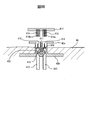
- the blood-returning plug 405 and the blood-removing plug 406 are formed of the same material as a commonly used rubber stopper for a blood collection tube, and the blood-removing puncture hollow body 414 and the blood-returning puncture hollow body 415 are used. Has a pierceable hardness.
- Reference numeral 407 indicates the carrier A.
- the transmission body 407 is formed of a rigid plastic or metal rod, and has one end connected to the operation unit 408 and the other end detachably connected to the opening / closing unit transmission body.
- Reference numeral 410 indicates a rotary valve.
- the rotary valve 410 is rod-shaped, and has a size at least in the short axis direction equal to or larger than the diameter of the tubular body. From the state in which the tubular body is locally compressed and closed from the side as shown in FIG. 4A, the tubular body is rotatable so as to be released from the local compression of the tubular body as shown in FIG. 4B.
- Reference numeral 411 is a guide body for keeping the track in order to cause the transmission body A 407 and the transmission body 409 for the rotary valve to rotate only, and to suppress the left and right displacement, and is made of a metal material such as a titanium material or a ceramic. Made of material.
- Both the blood removal section tubular body 413 and the blood removal puncture hollow body 414 are hermetically sealed inside the skin contact body 402 that comes into contact with the percutaneous skin, and block the infection path.
- Reference numeral 414 indicates a puncture hollow body for blood removal.
- the distal end of the blood removal puncture hollow body 414 has an acute angle so that at least the blood removal plug 406 can be pierced.
- the lid 417 can be formed of the same material as the cover member 401.
- a cap 418 for a blood removal part and a cap 419 for a blood return part that puncture and hold the puncture hollow body for blood removal 414 and the puncture hollow body for blood return 415 are provided on the bottom side of the lid part 417.
- the lid 417 is preferably used only for one-time use. Except for the lid, it has the same configuration as that of the percutaneous terminal shown in FIG.
- the rotary valve 410 presses the blood return portion tubular body 412 and the blood removal portion tubular body 413 from the outside, respectively, and closes them.
- the rotary valve 410 is moved from the blood removal puncture hollow body 414 and the blood return puncture hollow body 415 to the outside. Blood and the like are prevented from leaking.
- the lid portion 417 is removed, and the cover member 401 shown in FIGS. 4A and 4B is inserted and mounted.
- the blood removal plug 406 of the cover member 401 is connected to the blood return portion tubular body 412 and the blood return connector 403 by penetrating the blood removal puncture hollow body 414, and the blood return plug of the cover member 401 is connected.
- Reference numeral 405 connects the blood removal section tubular body 413 and the blood removal connector 404 by penetrating the blood removal puncture hollow body 414. By this piercing, the connector is fixed on the percutaneous terminal, and it is preferable that the connector is further fixed by the fixing band 416.
- the operation unit 408 When the operation unit 408 is rotated, the rotation is transmitted to the rotary valve 410 through the transmission body A 407 and the transmission body 409 for the rotation valve, and is rotated to reach the state shown in FIG. 4B, where blood flows into the blood circuit. Is done.
- the operation unit 408 is operated to rotate the rotary valve 410 to return to the state shown in FIG. 4A, and the blood return unit tubular body 412 and the blood removal unit tubular body 413 are closed inside.
- the rotary valve 410 only needs to be in a state in which the blockage of the blood return portion tubular body 412 and the blood removal portion tubular body 413 is released as shown in FIG. 4B only during treatment, and the cover member 401 is attached.
- a configuration that rotates only in the state is preferable.
- the present embodiment has a simple configuration, is easily connected to a blood circuit formed during hemodialysis, has no infection, etc., and has a configuration in which the burden on the patient is small.
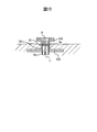
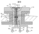
- reference numeral 701 indicates the lower part of the connector.
- the connector lower part 71 can be formed of resin, metal, ceramics, or the like. Inside the connector lower part 71, a blood removal flow path and a blood return flow path are formed. In addition, a fluid circuit configuration that opens and closes the flow path by an external driving operation to adjust the flow amount is provided. Have. Since the bottom portion of the connector lower portion has a contact surface with a living tissue, this portion is covered with a biocompatible member, or the connector lower portion 701 itself is formed of a biocompatible member.
- Reference numeral 8a indicates an artery, and reference numerals 8b and 8c indicate veins.
- Reference numeral 706 denotes a blood return tubular body. One end of the blood return tubular body 706 is connected to the vein 8c, and the other end is connected to the blood return puncture hollow body 710 via the blood return tubular body A708.
- Reference numeral 707 indicates a tubular body for blood removal.
- the blood removal tubular body 707 is connected to the venous tubular body A 705 and the arterial tubular body 704.
- the blood removal tubular body 707 is formed integrally with the arterial tubular body 704 and the venous tubular body A705, and preferably has no joint, and is a portion described for explanation in the embodiment.
- the blood removal tubular body 707 is arranged in the connector lower part 701 such that it can be deformed and closed by being pressed by the valve body 713.
- the support connection portion 712 connects the protrusion 711 and the valve body 713 with a rod-shaped shaft, rotates in the long axis direction, and transmits the rotation of the protrusion 711 to the valve body 713.
- Reference numeral 713 indicates a valve body.
- the valve body 713 has a rod shape, and can be pressed and closed by rotating the tubular body around the axis of the support connecting portion 712 by 90 degrees, for example. it can.
- Reference numeral 714 indicates a fixed stopper. As described above, the fixed stopper 714 is formed with the concave portion for fitting with the convex portion 711, and the fixed stopper 714 is fitted with the convex portion 711 to fix the valve body so as not to rotate. .
- Reference numeral 715 indicates a rod-shaped plug A. The rod-shaped plug 715 is inserted into the hollow portion of the puncture hollow body for blood removal 709 to prevent the hollow body 709 from being clogged with a thrombus or the like.
- Reference numeral 716 indicates a rod-shaped plug B.
- reference numeral 719 indicates the upper part of the connector.
- the connector upper part 719 incorporates a blood removal tubular body 720 for supplying blood to the blood circuit 6 outside the living body and a blood return tubular body 721 for returning blood returned via the blood circuit 6 to the body.
- a rotation operation section 728 for rotating the valve body is formed at the upper center.
- Reference numeral 720 indicates a tubular body for blood removal. One end of the blood removal tubular body 720 is connected to the blood circuit blood removal side tubular body 726, and the other end is connected to the stopper A722.
- Reference numeral 721 indicates a blood return tubular body.
- the driving concave portion 725 is for rotating the convex portion 711 and rotating the valve body 713 in a state fitted with the convex portion 711. It is preferable to be formed of a resin or metal having properties and durability.
- Reference numeral 726 indicates a blood removal side tubular body for a blood circuit.
- the blood circuit side blood removal side tubular body 726 corresponds to the blood removal side (arterial side) blood flow path 13 shown in FIG. 1, and reference numeral 727 is a blood circuit return side tubular body for the blood circuit. This corresponds to the blood removal side (artery side) blood flow path 16 shown. Specifically, as shown in FIG.
- the lid 702 has been removed from the connector.
- the stopper A 715 and the stopper B 716 are inserted into the puncture hollow body 709 for blood removal and the hollow body 710 for blood return puncture, respectively. Is released, but the state of the protruding portion 711 does not change and remains in a direction in which the valve body 713 is fixed, so that blood does not leak to the outside.
- the connector upper part 719 is attached instead of the lid part 702, and at the same time, the puncture hollow body for blood removal 709 and the hollow body for blood return puncture 710 penetrate the stopper A722 and the stopper B723, respectively.
- the tip of the drive transmission shaft 724 fits with the projection 711.
- valve element 713 closed the joint 704a between the arterial tubular body 704 and the venous tubular body A705 in the state of FIG. 7A, the closed state is gradually released by the rotation of the driving recess 725.
- the amount of rotation of the valve 713 allows the blood supply from the artery to be adjusted, and in fact, a shunt is formed only during dialysis treatment, so that some shunt complications may be improved.
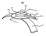
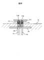
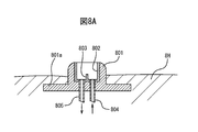
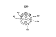
- reference numeral 801 indicates a terminal portion.
- FIG. 8A shows a cross section of the terminal portion 801 taken along a plane including the axis of the terminal portion 801.
- FIG. 8A shows the terminal portion 801 partially embedded in the patient's skin 8H.
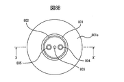
- FIG. 8B is a plan view of the terminal 801 as viewed from the top.
- Reference numeral 801a indicates the bottom edge of the terminal 801.
- the top peripheral edge of the upper portion of the terminal portion 801 is chamfered and rounded, and a concave portion is formed in the center of the upper portion of the terminal portion 801.
- FIG. 8A shows a cross section of the terminal portion 801 taken along a plane including the axis of the terminal portion 801.
- FIG. 8A shows the terminal portion 801 partially embedded in the patient's skin 8H.
- FIG. 8B is a plan view of the terminal 801 as viewed from the top.
- Reference numeral 801a indicates the bottom edge of the terminal 801.
- Reference numeral 804 indicates a tubular body for blood removal.
- the blood removal tubular body 804 is made of an artificial blood vessel used for a shunt for hemodialysis.
- Reference numeral 805 denotes a blood return tubular body, which is made of an artificial blood vessel used for a shunt for hemodialysis.
- Reference numeral 806 indicates a rotary valve.
- the rotary valve 806 has a disk shape or a cylindrical shape, and can be made of durable and biocompatible plastic, resin, or ceramic. The rotary valve 806 can rotate around a shaft 803.
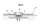
- Reference numeral 807 indicates a protective cover.
- the protective cover 807 is formed of a biocompatible metal, resin, or ceramic, is durable in the vertical direction, prevents rotation of the rotary valve in cases other than treatment, and returns to the tubular convex portion 808 for blood removal side connection. This is for protecting the blood-side connecting tubular convex portion 809 from the force from above.
- the blood removal side connecting tubular convex portion 808 is hollow and is formed integrally with the rotary valve 806.
- the blood removal side connecting tubular projection 808 is connected to a conduit extending from the dialysis device.
- Reference numeral 810 indicates an integral lid.
- the integrated lid portion 810 is formed after the dialysis treatment, and is formed of a laminated structure of ceramics and resin, or a structure of a filling material.
- the laminated structure means that a ceramic or resin powder is discharged and laminated by a so-called 3D printer, for example, an adhesive is discharged and cured sequentially to form a laminate, or a calcium phosphate-based powder is spread, and water, citric acid is dispersed. Or by laminating while discharging and curing an organic acid, or by irradiating a curing light such as ultraviolet rays while applying and spreading a photocurable resin powder. It is obtained by irradiating a laser beam and sintering the ceramic powder sequentially while spreading the ceramic powder.
- the penetrating object structure is a penetrating substance used for so-called dental treatment, and forms a resin-based penetrating substance used in the oral cavity to form an integrated lid portion 810, or free-cuts the shaped object.
- a CAM process for grinding and cutting based on a computer program based on a computer program for a porous ceramics (machinable ceramics) it may be fixed with an adhesive, and it is almost integrated and cannot be removed manually.
- a lid is formed. That is, the integrated lid portion is firmly joined so that it cannot be manually removed, and shows a state in which it looks at first glance as an integrated type.
- the integrated lid portion 810 cannot be removed alone, but is removed by a processing step such as cutting or melting, and when attached, is due to lamination hardening, so there is no infection from the percutaneous terminal and even in daily life. It does not require special protection and can be handled without burden.
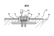
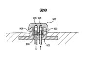
- Reference numeral 901 indicates a processing tool.
- the processing tool 901 is used to remove the integrated lid portion 810 by means such as cutting, grinding, melting, and evaporating.
- means for cutting, grinding, melting, evaporating and the like of the integrated lid portion 810 include milling, drilling, laser light, and the like, for example, removal processing by CAM (Computer Aided Machine) with reduced vibration, melting by laser light, Evaporation removal, rotary processing tools for resin, dental drills, end mills, and the like.
- CAM Computer Aided Machine
- the integrated lid portion 810 may have a low hardness and may be removed in a form that suppresses processing vibration.
- a resin cover it is easy to cut, and therefore, a material that is compatible with a living body and is easily cut is preferable.
- the integrated lid portion 810 is only required to withstand at least some external stimulus and to form a sealed state, does not necessarily require biocompatibility, is bonded by an adhesive or the like, and forms a state that cannot be easily removed. It should be done.
- the tight coupling to the guide body 802 can prevent bacterial infection and the like.
- Reference numeral 807 denotes a protective cover for preventing bacterial infection and removing external pressure to the rotary valve 806. It has a role of a protective cover, such as intrusion of residues when the lid 810 is removed, and protection from vibration during processing of the integrated lid 810.
- the protective cover 807 is made of resin or metal, and is made of non-deformable and sterile material.
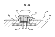
- the access connector 902 is a housing made of plastic or metal, has a robot arm structure, and extends from the dialysis device.
- the connection between the access connector and the dialysis machine is preferably of a flexible cord type so that the patient can relax during the dialysis time, but may be in the form of a robot arm for a short time.
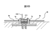
- the laser light is irradiated to form a laminate.
- curing light such as ultraviolet light is irradiated while the photocurable resin powder is discharged from the nozzle 1001 and spread, thereby forming the integrated lid portion 810.
- the above steps are preferably performed automatically by a CAM that includes one programmed computer process.
- the working unit by the CAM seals and holds the periphery of the terminal unit 801 embedded on the patient, and forms a sterilized working space at the top.
- the terminal section 801 is irradiated with ultraviolet rays and a disinfectant in a state where the working space is affirmed, and sterilized.
- FIG. 9A shows a hole-shaped upper holding portion 9s that holds the terminal portion 801 formed on the working portion bottom portion 9m.
- the working unit 9R is omitted except for the working unit bottom 9m.
- the integrated lid portion 810 is cut and removed by a cutting tool using a laser beam installed on a uniaxial or parallel link type manipulator.
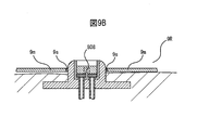
- the protective cover 807 is removed using a manipulator.
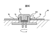
- the access connector 902 is connected using a manipulator in a state where the connector 903 for blood removal and the connector 904 for blood return of the rotary valve 806 are positioned so as to be connected to the tubular protrusions 808 and 809 for blood removal side connection.
- the access connector 902 is rotated to match or partially match the blood removal-side connecting tubular protrusions 808, 809 with the blood removal tubular body 804 and the blood return tubular body 805. Then, a blood circuit is formed so that blood can be supplied to the dialysis device.
- Reference numeral 905 indicates a blood removal conduit.
- the blood removal conduit 905 is connected to the blood removal connector 903 and is a tubular body for sending blood in the body to the dialysis device.
- Reference numeral 906 indicates a blood return conduit.
- the blood return conduit 906 is connected to the blood return connector 904 and is a tubular body for returning purified blood from the dialyzer to the body.
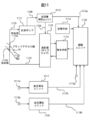
- FIG. 11 shows an embodiment of the hemodialysis apparatus of the present invention, which will be described. This embodiment also effectively works for treatment by ordinary puncture except when a percutaneous terminal is used for a blood access site.
- reference numeral 1111 indicates a blood pump.
- the blood pump 1111 is used when blood is extracted from the blood removal unit 1110a to the outside.
- the blood pump 1111 can generate a blood flow of 200 ml per minute as a standard value, for example, in order to secure a sufficient blood flow in a blood circuit 1100 generally formed outside the body.
- a roller pump can be used as the blood pump 1111.
- the roller-type pump may include an adjusting unit including an electric control circuit that adjusts the rotation speed of an impeller forming the roller unit.
- the adjusting means supplies the adjusted electrical output to the blood flow driving pump by the optimization signal output 1102a from the individual difference information managing means 1102, and is adjusted so that the rotation speed becomes an optimum state.
- the blood circuit indicates a path through which blood taken from a patient flows during dialysis treatment.
- Reference numeral 1112 denotes a dialyzer, which is formed by a dialyzer and is formed by a bundle of hollow fibers having holes in about 10,000 insides, in which blood circulates inside and the outside flows in reverse to the flow of blood. A configuration is provided in which the dialysate circulates in the direction.
- Reference numeral 1113 denotes a blood volume measurement unit, which is configured by a blood volume meter, a laser blood flow meter, or the like. For example, a laser beam is irradiated from the outer surface of a conduit constituting a blood circuit, and reflected from internal red blood cells and the like. After deriving the blood volume from the sensor and the sensor that receives light outside the conduit, the PRR value or the like is calculated and output to the adjustment unit 1116 as an electric signal.
- waste products are conveyed, waste products are discharged to the outside by a filter or the like, and a body fluid for the purpose of dewatering is discharged to a predetermined outside by an external drive unit and manual operation. It is for discharging at a speed.
- the water removing means 1115 may be incorporated in a general hemodialysis apparatus, but a driving body for automatically controlling an outlet for discharging body fluid to the outside may be separately provided.
- Reference numeral 1116 indicates an adjustment unit.
- the adjustment unit 1116 includes a computer, a server, a cloud server, and the like, and is connected to the blood volume measurement unit 1113 via an electric lead wire 1113a to input blood volume data.
- the blood pressure measurement unit 1117 is connected to the blood pressure measurement unit 1117 via an electric lead wire 1117b, and the blood pressure data is input to the adjustment unit 1116.
- the blood pressure measurement unit 1118 is connected to the blood flow measurement unit 1118 via an electric lead wire 1118b, and inputs blood pressure data to the adjustment unit 1116.
- Reference numeral 1116a denotes a manual operation input unit, which is constituted by a button switch, a rotary dial, and the like.
- a doctor, a nurse, or the like manually inputs a signal to drive the water removing unit 1115 or performs water removal. This is a part for performing a dialysis operation such as reading a pattern from the storage unit 1114 and setting a water removal pattern.
- the adjusting unit 1116 includes a robot and a robot-type manipulator for performing a water removal amount adjustment drive and a water removal speed adjustment drive of the computer and the water removal unit 1115, and physically operates the water removal unit 15.
- a drive manipulator may be provided.
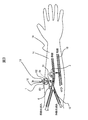
- FIG. 12A shows the continuous blood pressure measurement unit in a state of being wound around and attached to the upper arm 12h.
- FIG. 12B is a sectional view taken along line X-X ′ of FIG. 12A.
- a pulse wave sensor as a light emitter for detecting deep arterial waves is used.
- reference numeral 1201 indicates a band.
- the belt-like body 1201 is formed of vinyl, plastic, or cloth, surrounds a living body such as a supporter, and is fixed at that position, and is configured to have elasticity with a flexible resin, cloth, or the like. I have.
- the upper arm is pressed from the surroundings by the elasticity of the band-shaped body 1201, but the force is preferably such that the sensor in the band-shaped body 1201 does not move.
- the width of the band-shaped body 1201 is, for example, about 4 cm to 6 cm, and preferably 4.5 cm to 5.5 cm. However, the width is not limited to this value as long as it is a state in which a pulse wave can be suitably detected.
- Reference numeral 1202 indicates a housing.
- the housing 1202 is formed of plastic, metal, or the like, and houses an antenna for wireless communication, an electric circuit board, a battery, and the like.
- the housing 1202 includes a blood pressure measurement unit 1117 including a computer unit shown in FIG. 11, and data can be transmitted to the adjustment unit 1116 by WiFi. Further, inside the housing 1202, transmission / reception for infrared light, WiFi, Bluetooth (trademark) for wirelessly transmitting a pulse wave electric signal obtained from a light receiving unit for detecting green light and infrared light to the outside.
- An electronic circuit module is built in.
- Reference numeral 1203 indicates an infrared (IR) light emitting unit.
- the infrared (IR) light emitting unit 1203 includes an LED, a light emitting diode, and the like that output infrared light at a wavelength of 850 nm, and measures the blood flow to the deep artery 12d of the upper arm.
- Reference numeral 1204 denotes a light receiving unit for infrared (IR) light.
- the infrared (IR) light receiving unit 1204 includes a phototransistor, a photodiode, and the like.
- Reference numeral 1205 indicates a black sheet.
- the black sheet 1205 is made of a sheet material having black rubber, resin, and plastic flexibility, and includes an infrared (IR) light emitting unit 1203 and an infrared (IR) light receiving unit 1204. In between, light other than light transmitted through the body is removed.
- Reference numeral 1206 indicates a sensor unit for green light.
- the green light sensor unit 1206 includes a green (G) light emitting unit 1206a and a green (G) light receiving unit 1206b. The green light output to the inside of the body 4h is reflected by the thin artery 12s, and the reflected light is received by the green (G) light receiving unit 1206b.
- Reference numeral 1207 indicates a green light electrical connection.
- the green light electrical connection unit 1207 includes an electrical lead wire, a connector, and the like, and supplies an electrical signal to the green (G) light emitting unit 1206a, and receives the reflected light from the green (G) light receiving unit 1206b.
- Reference numeral 1208 indicates an electrical connection for infrared emission.
- the infrared light emitting electric connection portion 1208 is configured by an electric lead wire 1210 for outputting infrared light, a connector, and the like, and is a conductive connection portion for outputting electric power to the infrared (IR) light emitting portion 1203.
- Reference numeral 1209 indicates an electric connection portion for infrared transmitted light.
- the infrared transmitted light electrical connection unit 1209 includes an electric lead wire 1211 for transmitting an infrared light reception signal, a connector, and the like, and is output by the infrared (IR) light reception unit 1204.
- Reference numeral 1210 indicates an infrared light output electrical lead wire for transmitting an electric output to the infrared light emitting unit.
- the electric lead wire 1210 is for electrically connecting the infrared light emitting electric connection portion 1208 and the infrared (IR) light emitting portion 1203.
- Reference numeral 1211 denotes an electric lead wire for an infrared light receiving signal for transmitting an electric output from the infrared light receiving unit to the housing 1202.
- the electric lead wire 1211 is for electrically connecting the infrared light emitting electric connection section 1208 and the infrared (IR) light emitting section 1203.
- the belt-like body 1201 is formed in a cylindrical shape having elasticity like a supporter, for example, and is mounted around a human or one of the right and left upper arms as shown in FIG. 12A.
- the infrared pulse wave sensor including the infrared (IR) light emitting unit 1203 and the infrared (IR) light receiving unit 1204 may be mounted so as to be located under the armpit, and may be of a transmission type with respect to the deep thick artery 124d. It is preferable in detecting a pulse wave. However, depending on the state of the subject's artery, the infrared (IR) light emitting unit 1203 and the infrared (IR) light receiving unit 1204 may be arranged outside the upper arm.
- the housing 1202 is provided with an electric circuit for transmitting and receiving the LED reception signal to the outside by wireless or wired communication such as WiFi and infrared rays, and is so-called IoT, and further includes a battery unit such as a button battery. .
- the start of use is performed by turning on a switch provided in the electric circuit and turning on a membrane switch or the like which is turned on simultaneously with mounting.
- the electric circuit in the housing 1202 supplies an electric signal to the infrared (IR) light emitting unit 1203 via the electric lead 410.
- IR infrared
- the infrared (IR) light emitting unit 1203 outputs infrared light having the above-described wavelength.
- the light passes through the thick deep artery and is received by the infrared (IR) light receiving unit 1204.
- This light receiving signal is converted into an electric signal and supplied to an electric circuit in the housing 1202 via the electric lead wire 1211.
- This electric signal is transmitted via an antenna connected to an electric circuit in the housing 1202 to an operation terminal 1205 such as the operation terminal 1205 shown in FIG. Sent.
- the green (G) light emitting section 1206a of the green light sensor unit 1206 irradiates the peripheral blood vessels 12s (22 in FIG. 13B) with green light, receives the green (G) light receiving section 1206b, and receives the received light signal.
- the green pulse wave electric signal is output to the housing 1202 after being converted into an electric signal.
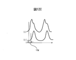
- the received light pulse wave signals 01 and 02 shown in FIG. After being sampled by, it is converted into digital numerical data and transmitted to the outside.
- the operation terminal 805 restores the input digital data to form an analog signal, and then performs a secondary differentiation process on the analog signal.
- the second derivative signal may be sampled and transmitted to the operation terminal 805.
- the blood pressure-related value and the blood pressure value are quickly calculated. it can.
- the blood pressure value is an estimated value, and since at least the amount of change is sufficient, the time phase of the rise of the pulse wave detected from the artery deep in the body and the time phase of the rise of the pulse wave detected from the artery shallow from the body skin It is sufficient to find the time difference (phase difference) of 12g in FIG. 12C.
- the change in the phase difference can indicate an increase or decrease in blood pressure (PWTT is an electrocardiogram and a pulse wave, but a pulse wave of a thick artery deep in a living body is in a shallow place because the timing almost coincides with the electrocardiogram signal. This is almost similar to the phase difference between the pulse wave of the thin artery and the deep artery.)
- Electrical leads 1113a, 1117b, and 1118b shown in FIG. 11 may be, for example, wirelessly connected by a wireless operation unit (ZigBee or the like) of WiFi, Bluetooth (registered trademark) connection.
- a wireless operation unit ZigBee or the like
- WiFi Wireless Fidelity
- Bluetooth registered trademark
- a blood access portion is formed by puncturing and fixing a blood removal portion 1110a and a blood return portion 1110b to a blood vessel using a hollow needle in the vicinity of an upper arm portion 1110 having a shunt portion provided for performing dialysis treatment. I do.
- An extracorporeal blood circuit 1100 is formed between the blood removal unit 1110a and the blood return unit 1110b of the blood access unit.
- an appropriate treatment is started based on the patient's treatment history data read from the storage unit 1114 by operating the adjustment unit 1116, the blood pressure data input from the blood pressure measurement unit 1117, and the blood flow data input from the blood flow measurement unit 1118.
- An appropriate water removal pattern is selected from FIGS. 3C and 3D at the time and other predetermined water removal patterns. This choice is made by physicians, nurses, and clinical technicians, or when the data volume increases, based on data (dialysis temperature data, body weight data, water removal rate data, etc.) during the dialysis treatment before the patient.
- a machine learning process, a deep learning process such as a neural network, or the like may be performed in advance, and may be selected predictively by applying it to the obtained correspondence data.
- the corresponding data in this case is a decision tree in which body temperature data, weight data, water removal rate data, and the like are used as explanatory variables, and blood pressure stable state (maximum fluctuation range of blood pressure) data during dialysis treatment is used as a selection variable. Then, when patient data such as body temperature data is input as data including a blood pressure stable boundary obtained after the ensemble learning, a blood pressure stable state that is uniquely indicated is exemplified.
- the adjustment unit 1116 sets a water removal pattern for the patient, inputs other dry weights and the like, and sets a specific water removal rate. For example, the adjustment unit 1116 dialyzes at the water removal rate of the pattern shown in FIG. 13C or 13D. Treatment begins.
- the blood flowing through the blood circuit 1100 is passed through a dialyzer 1112, and the waste and the body fluid that have permeated and infiltrated to the outside of the hollow fiber due to the difference in concentration are transported to a buffer solution, transported to a water removing means 1115, and
- the water removal valve (not shown) is opened at a setting corresponding to the water removal speed set by the output signal, and the body fluid is discharged to the outside.
- the blood volume measurement unit 1113 detects the blood volume (BV value) in the blood circuit 1100 and calculates the PRR value from the blood volume.
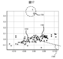
- the PRR (plasma refilling rate) value is an estimated value calculated from a BV meter or the like, which is a ratio (velocity) of a body fluid that enters a blood vessel from outside the blood vessel into the blood vessel. For example, the change in the PRR value is shown by a solid line in FIG.
- the adjusting unit 1116 performs a drive to the water removing means 1115 so as to reduce the water removing speed and narrow the opening area of the water removing drive valve.
- the adjustment unit 1116 instructs the water removal means 1115 to increase the water removal speed by increasing the opening area of the water removal drive valve.
- the predetermined value of the PRR value may be set in advance based on the dialysis history data of the patient and individual differences of the patient. In the case of manual operation, the change in the PRR value is set as a guide while observing the change in the PRR value with a computer monitor or the like. Is also good.
- the predetermined value is determined depending on the individual difference of the patient. For example, the predetermined value may be a value in a case where the rate of change in the blood pressure value measured at the same time is small and the water removal rate is adjusted.
- the blood pressure measurement unit 1117 can input the blood pressure of the patient over time from the blood pressure input terminal 17a and monitor whether the blood pressure is stable, when the change in the blood pressure becomes a predetermined value or more, the adjustment unit 1116 is used. Output a signal to that effect. Since the blood flow measurement unit 1118 can input the blood flow of the patient over time from the blood flow input terminal 1118a and monitor whether the blood flow is stable, the change in the blood flow has exceeded a predetermined value. In this case, a signal to that effect is output to the adjustment unit 1116.
- the falling rate of the PRR value output from the blood volume measurement unit 1113 is not more than the predetermined value.
- an instruction to reduce the water removal speed of the water removal means 1115 may be issued.
- the water removal rate is adjusted according to the change in the PRR value calculated from the blood volume measurement unit 1113, and when the blood pressure measurement value of the blood pressure measurement unit 1117 becomes larger than a predetermined value or When the difference between the blood flow values of the respective parts output from the measurement unit 118 becomes equal to or greater than a predetermined value, the patient can perform sufficient dialysis treatment under stable blood pressure by increasing or decreasing the water removal rate. I can do it.
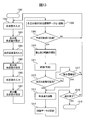
- FIG. 13 shows a flowchart, which is stored in the storage unit 1114 as a program of the adjustment unit 1116 constituted by the computer shown in FIG. 13, and is loaded into the computer and executed.
- the flowchart shown in FIG. 13 is an example of a machine learning program using a clustering method in artificial intelligence, and is composed of, for example, a Python program using a Scikit-Learn module. Only the main part of the program function is shown.
- the program code shown in FIGS. 15A-15B The program codes shown in FIGS.
- 15A and 15B are such that the change amounts of the blood pressure data and the blood flow data are sent from the blood flow meter and the blood pressure monitor in the CSV file format by 100 from the outside, and are sent 300 times with the number of centroids being 3 2 shows a part of a clustering process for making a two-dimensional graph for performing learning and a time-series liquid three-dimensional data to be displayed.
- Step 1301 is a start step
- step 1302 is a step for obtaining a blood volume and a PRR value by the blood volume measurement unit 1113 shown in FIG. 1
- step 1303 is a PRR value or a blood volume obtained in the step 1302.
- This is a step of calculating a difference value, which is a step of performing arithmetic processing by a computer of the adjustment unit 1116.
- Step 1304 is a step of obtaining blood flow data obtained from the patient's head, neck, hands, feet, and the like by the blood flow measurement unit 1118 shown in FIG.
- the blood flow measurement probe or sensor connected to 1118a of the blood flow measurement unit 1118 is a device that irradiates near-infrared rays and obtains blood flow from its reflected wave, and is used by being attached to the head or used near the shunt. It is placed and fixed near the heart and used.
- Step 1305 is a step of obtaining a blood flow difference value from the blood flow data obtained in step 1304, and is a step of performing arithmetic processing by the computer of the adjustment unit 1116.
- Step 1306 is a step of obtaining blood pressure data obtained from the patient by the blood pressure measurement unit 1117 shown in FIG. 11.
- Step 1307 is a step of obtaining a blood pressure difference value from the blood pressure data obtained in Step 1306. This is a step of performing arithmetic processing by the computer of the unit 1116.
- Step 1308 is a step for forming each difference value as two-dimensional coordinate data.
- the difference value blood volume data, the difference value blood flow data For example, the horizontal axis represents the differential blood volume data, the vertical axis represents the differential blood pressure data, the vertical axis represents the differential blood pressure data, and the horizontal axis represents the differential blood flow data, and the vertical axis represents the differential blood pressure data.
- This is a step of converting into coordinate data so as to become data.
- Step 1309 is a step of judging whether a predetermined period has elapsed or the amount of data has reached a predictable state. If the amount of coordinate values or another cluster occurs, the data up to that point is determined. It is set as one predetermined period. That is, when a cluster exceeding the preset number of clusters occurs, the evaluation may be changed to the evaluation of the next predetermined period, in which case, the evaluation is set in advance corresponding to the number of the predetermined period from the start of dialysis. The number of clusters may be changed. By combining data converted into two-dimensional coordinates for a predetermined period as time on the z-axis, changes in blood pressure, blood flow, and blood volume are shown in time series, and prediction of blood pressure fluctuation after a long time becomes possible. .
- Step 1310 is a step of deriving a feature point and a feature range.
- the feature point indicates the center of gravity in the case of a cluster
- the feature range indicates the range of one cluster
- the repetitive calculation is performed while changing the center coordinates so that the Euclidean distance from the center of gravity coordinates becomes the shortest. Done and decided.
- Reference numeral 1311 denotes a step of performing evaluation and prediction.
- the horizontal axis is a blood flow difference value
- the vertical axis is a blood pressure difference value
- the coordinates of the center of gravity are at the center
- the range of the cluster is at the center of the coordinates.
- Step 1312 is a step of receiving the evaluation result of step 1311 and determining the possibility of a change in blood pressure.
- Step 1313 is a step in which the adjustment unit 1116 shown in FIG. 1 outputs a signal for reducing the water removal speed to the water removal means 1115 when there is a possibility that the blood pressure may fluctuate.
- step 1314 the adjustment of the water removal amount is recorded with time, the evaluation content in step 1311 is stored, and the history data of the water removal operation is formed, and stored in the storage unit 1114 shown in FIG. 11 as patient data. It is a step to do.
- the data stored in this storage means is used for selection of the initial water removal speed pattern shown in FIG. 19, and may be recorded and registered so as to be usable as big data by an external cloud computer.
- Step 1315 is a step of confirming completion of dialysis
- step 1316 is a termination step.
- Step 1317 is a step of examining the possibility of an increase in the amount of water removal. For example, in the relationship between the PRR value and the water removal speed shown in FIG. It is calculated from the flow rate, and it is further confirmed whether or not the timing at which the change direction of the blood flow and the change direction of the blood flow coincide. If both coincide, the control signal for increasing the amount of water removal by 10% on a trial basis and the notification Generate a signal.
- FIG. 13 shows a step subsequent to the step of selecting a water removal pattern according to the individual difference in the embodiment shown in FIG.
- the embodiment of the present invention may be implemented only by the step shown in FIG. 13 without the step of selecting the water removal pattern according to the individual difference.
- Adjustment of the water removal rate based on the PRR value is only a minimum adjustment, and while performing adjustment to increase or decrease the water removal amount based on the change amount of the blood pressure data and the blood flow data, the target water removal is performed. Must be completed within a predetermined time.
- the blood pressure value is input, and respective difference data is formed (steps 1303, 1305, and 1307).
- the difference value is for enabling at least the obtained biological signal to be converted into coordinates of two or more dimensions, and even if it is another transformation, if a relationship having regression and correlation is formed, There is no particular limitation.
- Each of the difference values has been converted into a value that can be coordinated on the same two-dimensional coordinates.
- two-dimensional coordinate data of the difference value data at the same time for example, with the blood difference value as the horizontal axis and the blood pressure difference value as the vertical axis, is performed for a predetermined period (step 1308). Further, two two-dimensional coordinate data is formed with the horizontal axis of the blood flow difference value, the vertical axis of the blood pressure difference value, or the horizontal axis of the blood flow difference value and the vertical axis of the blood difference value.
- step 1310 a feature point and a feature range are derived.
- a change in blood pressure is predicted and evaluated from the obtained feature points (centroid: centroid) and the range of one cluster (feature range). For example, if the horizontal axis is the blood flow difference value and the vertical axis is the blood pressure difference value, the coordinates are considered to be related to the degree of change in the intravascular volume.
- the adjustment unit 1116 performs an operation to the water removing means 1115 to reduce the water removal rate and reduce the water removal amount (step 1313).
- the water removal amount is recorded in the adjustment data together with the time information from the start of the dialysis treatment in the storage unit 1114.
- the blood pressure data and the blood flow data are referred to whether the water removal amount can be increased. If the blood pressure data and the blood flow data are within the permissible water removal range and the amount of water removal is available, the increase in the amount of water removal is adjusted (step 1313). In step 1317, there is no room to increase the amount of water removal. (No) returns to the blood volume input step (1302) again to perform the data input operation.
- the dialysis time ends (step 1315) (yes)
- the dialysis treatment ends (step 1316).
- the data before dialysis treatment obtained based on the relationship between the blood pressure and the blood flow described above, the time from the dialysis start time, the water removal amount, the number of clusters, the coordinates of each center of gravity, the range of the cluster, and the evaluation items are listed.
- individual difference pattern data at the time of dialysis treatment of a patient can be obtained.
- the evaluation items are set, for example, in five stages. When the patient is formed when gentle dialysis treatment is performed, 5 is added, and when the patient is not gentle, 1 is added, for example. , A rule is created in advance, and a value corresponding to the rule is assigned. This is sequentially recorded, a dialysis treatment pattern database of the patient is formed, and continuous recording is performed on a hard disk such as a computer, a USB memory, a server, or the like.
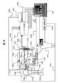
- Reference numeral 1401 indicates a dialysis device.
- the dialysis device 1402 include existing dialysis devices, for example, HD and HDF type dialysis devices.
- Reference numeral 1401a denotes a blood pump for circulating blood drawn from the body through the dialyzer 1401 and the dialyzer 1402. Blood pump 1401a can be a rotary pump.
- Reference numeral 1401b indicates a blood tube A for transporting blood from the body to the dialyzer 1402 via a blood removal unit. Blood passes through the inside of the blood tube A.
- the blood tube A is formed of a transparent and translucent resin.
- Reference numeral 1401c indicates a blood tube B for returning blood from the dialyzer 1402 to the blood removal unit 1412b.
- Reference numeral 1402 indicates a dialyzer (dialyzer).
- the dialyzer 1402 can be an off-the-shelf product in which the side surface of the housing is formed of a transparent or translucent material.
- Reference numeral 1403 indicates a laser blood flow meter. As an example of the laser blood flow meter 1403, a Doppler laser blood flow meter can be given, and a laser Doppler blood flow meter capable of measuring in a wide frequency band (about 150 KHz to about 500 KHz) is preferable.
- Reference numeral 1403a indicates a blood flow meter probe for a dialyzer.
- the dialyzer blood flow meter probe 1403a includes an irradiation unit that irradiates a laser beam, and a light receiving unit that receives the laser beam from the irradiation unit.
- the irradiation unit and the light receiving unit of the probe 1403a may be arranged so as to face each other at a predetermined angle.
- two probe units (an irradiation unit and a light receiving unit) may be fixed so as to face the side surface of the dialyzer 1402.
- Reference numeral 1403b indicates the transmission member A.
- the transmission member 1403b is formed of an optical fiber or an electric lead wire, and is for transmitting light received by the blood flow meter probe or an electric signal obtained by photoelectric conversion to the laser blood flow meter.
- Reference numeral 1403c indicates a patient blood flow meter probe.
- the patient blood flow meter probe 1403c has a reflection type configuration in which an irradiation unit that irradiates a laser beam and a reflection return unit that reflects off tissue in the skin are arranged at a predetermined angle.
- an irradiation unit that irradiates a laser beam and a reflection return unit that reflects off tissue in the skin are arranged at a predetermined angle.
- the patient's blood flow meter probe 1403c measures, for example, an earlobe or the like, one side receives a light-emitting body and the other side receives a light-receiving body image.
- Reference numeral 1403d indicates a transmission member B using an optical fiber, an electric lead, or the like.
- As the transmission member 1403, a transmission cable for a blood flow meter attached to the patient 1406 is exemplified.
- Reference numeral 1403e indicates an electric transmission path.
- the electric transmission path 1403e is a transmission path for transmitting a medium such as a wired cable such as a LAN cable and a USB cable, WIFI, infrared rays, and Bluetooth (registered trademark).
- Reference numeral 1404 denotes a continuous sphygmomanometer.
- the continuous sphygmomanometer 1404 detects, for example, a pulse wave at a deep place and a pulse wave at a shallow place below the band attached to the upper arm as shown in FIG. Calculate the blood pressure value.
- the continuous sphygmomanometer 1404 estimates and measures the blood pressure value based on, for example, the method of Japanese Patent Application No. 2019-35914. It is to be noted that the blood pressure value need not be calculated but may be the change amount. Since the change amount is a relative value, the first reference blood pressure value may be measured in some cases.
- a computer unit having an OS such as WINDOWS (registered trademark), Linux, or MACOS is connected to a data output unit, and a WiFi module and Bluetooth (registered trademark) are connected.
- the OS includes a data output unit for data sharing and remote desktop connection, and a data input unit for converting an analog signal into a digital signal by an AD converter for processing.
- Reference numeral 1404a indicates a pressureless cuff for upper arm mounting.
- the non-pressure cuff 1404a for wearing the upper arm includes an infrared light emitter, a green light emitter, a continuous projection for blocking light leakage from the outside when wound and mounted, an electrocardiogram electrode, and a pneumatic bladder containing a heart sound sensor.
- Reference numeral 1404b indicates a transmission path.
- the transmission path 1404b is formed of an electric wire cable, a wireless medium, or the like, and transmits blood pressure value data or the like obtained by the non-pressure cuff for upper arm mounting to the continuous sphygmomanometer 1404 or processes data with the continuous sphygmomanometer 1404 Is a transmission path for transmitting a pulse wave signal and an electrocardiogram signal for calculating and calculating blood pressure data.
- Reference numeral 1404c indicates a data transmission path.
- the data transmission path 1404c is formed of a USB cable, a LAN cable, or the like, and is a cable or a wireless medium for transmitting a blood pressure value to the computer terminal 1405.
- Reference numeral 1405 indicates a computer terminal.
- the computer terminal 1405 includes a storage device such as a hard disk and a USB memory, and includes a processing execution unit that executes based on a program stored therein.
- the computer terminal 1405 preferably also includes a display monitor, a computer mouse, a keyboard, a touchpad, and a touchpad-type display monitor.
- the computer terminal 1405 executes the machine learning algorithm and the deep learning algorithm described above as a program.
- Reference numeral 1405a indicates a data transmission path for a dialysis device.
- the dialysis device data transmission line 1405a is configured by WiFi, wireless LAN, wired LAN, infrared communication, BlueTooth (registered trademark), or the like, and is a transmission line for transmitting data to the dialysis device 1401 or performing remote control.
- Reference numeral 1405b indicates a screen / audio output unit. Examples of the screen / audio output unit 1405b include a computer display, a speaker, and an earphone.
- the screen / audio output unit 1405b displays, for example, when the blood flow is unstable and the heart rate rises, or when there is a possibility that a rapid change in the blood pressure may occur within ten and several minutes, And a sound is notified to a doctor or the like.
- Reference numeral 1405c indicates a patient transmitting means.
- the patient transmission unit 1405c is a transmission body for performing screen display and audio display to the patient, and is formed of a wireless or LAN cable such as WiFi, infrared, Bluetooth (registered trademark), or the like.
- Reference numeral 1406 indicates the patient.
- a blood access unit 1412 composed of a blood removal unit for supplying blood to the dialysis machine and a blood return unit for returning purified blood obtained by purifying blood to the body with a dialyzer. Have been.
- Reference numeral 1407 indicates a dialysis treatment worker such as a doctor, a nurse, or a clinical engineer.
- Reference numeral 1408 indicates a dialysate circuit.
- the dialysate circuit 1408 has a built-in pump and the like for forming a dialysate flow, is configured to flow dialysate upward from below the dialyzer through dialysate tubes 1408a and 1408b, and water and waste to the outside.
- Reference numeral 1409 indicates a replacement fluid supply unit.
- the replacement fluid supply unit 1409 is a supply unit when the physiological saline and necessary components are removed.
- Reference numeral 1410 indicates a control operation unit.
- the control operation unit 1410 has the same configuration as a computer system including a display monitor, a computer mouse, a touch pad, a keyboard, a CPU, a GPU, and the like.
- Reference numeral 1411 indicates a water removal adjusting unit.
- the water removal adjustment unit 1411 is formed of an electrically controllable valve or valve such as an electromagnetic valve, and performs an opening / closing operation or the like by an external electric signal.
- Reference numeral 1412 indicates a blood access unit.
- the blood access unit 1412 includes a blood removal unit that extracts blood from the vein in the vicinity of an inner shunt that connects an artery and a vein with a puncture hollow needle, and a dialyzer 1402. It consists of a hollow needle punctured into a vein to return the blood purified in the above to the body.
- a non-pressure cuff for mounting an upper arm 1404a is wound around the upper arm of the dialysis patient so that the patient does not feel pressure and the sensor is in close contact with the skin and fixed. It is preferable that the fixing can be performed by abutment such as a planar fastener. However, it is preferable that the non-pressure cuff for mounting the upper arm 1404a is fixed to the upper arm so as not to slide down and that the patient is not burdened.
- Reference numeral 1404a is a non-pressure cuff for upper arm, which detects a pulse wave of an artery in a deep part from the skin by an infra-red infrared pulse wave sensor and a pulse wave of a shallow artery from the skin by a green sensor. If the pulse wave of the artery deep from the skin by the infrared pulse wave sensor is difficult, electrodes for measuring at least one lead of the electrocardiograph may be attached to both arms, for example, with the heart in between, or cuffed It is preferable to use it while holding it in a form of being clamped and fixed.
- the rising pulse signal of the infrared pulse wave signal and the green pulse wave signal obtained by the upper arm-mounted non-pressure cuff 1404a is transmitted to the continuous sphygmomanometer 1404 via the 1404b.
- the continuous sphygmomanometer 1404 may be miniaturized and housed and integrated in the upper arm-mounted non-pressure cuff 1404a.
- the continuous sphygmomanometer 1404 further transmits data to the computer terminal 1405.
- the data is processed in advance, and the data is measured, for example, at sample points (at intervals of 0.1 to 10 seconds), and the CSV file
- the file is transmitted to the computer terminal 1405 or the folder is shared, and the computer terminal 1405 detects and processes the file when the file is stored in the folder.
- An embodiment such as a batch processing format may be used.
- the blood flow data detected from the blood flow meter probe 1403c for the patient mounted on the abdomen and limbs of the patient 1406 is transmitted to the laser blood flow meter 1403 via the transmission member B1403d.
- the transmission member B1403d is an optical fiber
- the blood flow data is transmitted as reflected return light to the laser blood flow meter 1403
- the blood flow meter probe 1403c for a patient is a laser output chip and a light receiving semiconductor element
- an electrical signal is transmitted. Is transmitted to the laser blood flow meter 1403.
- the laser blood flow meter 1403 calculates a blood flow velocity and a blood flow from the received signal, and outputs the calculated data to the computer terminal 1405.
- the laser blood flow meter 1403 receives the reflected light or transmitted light detected by the dialyzer blood flow meter probe 1403a connected to the dialyzer 1402, and is input to the laser blood flow meter 1403 via the transmission member A1403b.
- the values are converted into target values such as the flow velocity and the blood flow rate, and transmitted to the computer terminal 1405.
- the computer terminal 1405 monitors blood flow data and blood pressure data over time. The change amount of the two for a predetermined time is taken. Since blood flow data frequently fluctuates due to sympathetic nerve and skin stimulation, a baseline is extracted to clarify changes in blood flow due to water removal.
- the baseline is indicated by reference numeral 1603 in FIG.
- This baseline is based on the tendency of the blood flow to decrease due to the amount of water removed, detects the lowest value of the blood flow waveform that occurs in time series, connects the values, and acquires values at predetermined intervals at the time of connection. And the amount of change for each sample interval.
- Reference numeral 1601 indicates a blood pressure waveform. This waveform shows the changes in blood flow and blood pressure during dialysis treatment of Case 1 as a result of literature (http://www.tokyo-hd.org/pdf/44th/44th_04_18.pdf Study on the usefulness of laser blood flow meter). Based on a portion of the chart shown.
- FIG. 17 shows a chart 60 minutes after the start of dialysis.
- the blood flow output and the blood pressure output are respectively converted into digital signals by an A / D converter, coordinated, and then, at predetermined intervals, a blood pressure value and a blood flow value are detected.
- the relationship is made into a scatter diagram by 100 points, and the center of gravity point determined by learning by the clustering process is extracted, and its change is monitored to predict a change in blood pressure.
- 15A and 15B show a part of the program code created by Python 3.6. In the program code of FIGS. 15A-15B
- FIG. 17 shows an example of the dispersion diagram.
- the vertical axis indicates the amount of change in blood flow
- the horizontal axis indicates the amount of change in blood pressure. This is the point in time when the blood pressure data has started to be measured 30 minutes after the start of measurement.
- Reference numerals 1701, 1702, and 1703 denote centroids, each of which indicates the centroid value of the blood pressure value.
- the center of gravity indicated by reference numeral 1702 is a single plot. The reason for adopting the three centers of gravity is to obtain further centers of these centers of gravity and track the time-series displacement of the centers.
- the number of centers of gravity may be a number other than three.
- Reference numeral 1701 shows a change amount of one blood flow and blood pressure in a state where only the center of gravity is shown.
- Reference numeral 1704 indicates a boundary where the two areas are divided by the program based on the result of learning 300 times. On a computer monitor, the screen is color-coded.
- the state of the blood flow and the blood pressure are four change direction areas (positive blood flow direction, positive blood pressure direction), (negative blood flow direction, positive blood pressure direction), (positive blood flow direction, negative blood pressure direction), and (blood flow (Minus direction, blood pressure minus direction) can be set, and the two pieces of information can be easily viewed in one form, and the tendency can be easily recognized by the center of gravity processing.
- a change in a decrease in blood flow and a change in an increase in blood pressure at the time of vasoconstriction can be confirmed in a concentration range of the center of gravity, and a change in a blood vessel state can be confirmed based on time information.
- the change in the center of gravity is notified to the dialysis treatment worker 1407 by a screen or voice of the computer terminal 1405 shown in FIG. 14 (screen / voice output unit 1405b).
- a control signal is directly output to the dialysis machine 1401 (data transmission line 1405a for the dialysis machine).
- the patient 1406 is also notified of the change (patient transmission means 1405c), and asked if there is any deficiency in physical condition. By recording the response from, the data can be further used as teacher data for machine learning.
- FIG. 18 shows a configuration for detecting a baseline (baseline) of internal blood flow data, which will be described.
- FIG. 18 shows a part of the steps of detecting a baseline and converting it into data.
- FIG. 18 is a flowchart for obtaining baseline data of internal blood flow data.
- Step 1801 is a step in which the blood flow value at the sample point of the blood flow waveform is sampled with a fixed time width. It is shown in FIG. 16B.
- the fixed time interval is, for example, a time width from 100 msec to 1 minute, and may be selected in other cases. However, if the time interval is long, the data becomes coarse, and the detection frequency of the minimum value is determined. When the time width is shortened, the data is segmented and the minimum value can be accurately detected, but the processing time may be long.
- Step 1801 is time setting for facilitating the description of the baseline setting operation.
- Step 1802 is a step for determining the next sample point BFN.
- the sample time is the time width described above.
- Step 1803 is a step of judging the magnitude of the current sample point BFG and the next sample point BFN to be equal and equal.
- Step 1804 is a step of determining whether or not the previous mode is ascending or descending. The previous mode indicates a slope in the mode determined by the sample point immediately before the current sample point and the current sample point.
- Step 1805 is a step of determining whether the previous mode is up or down.
- Step 1806 is a step of setting BFG (current sample point) as the maximum value.
- Step 1807 is a step of temporarily storing that the next sample point BFN is in the descending mode.
- Step 1808 is a step of determining that the sine pull point of the BFG is the minimum value.
- Step 1809 is a step for indicating that the BPN is in the ascending mode.
- Step 1810 is a step of determining whether or not there is a minimum value BFG ( ⁇ 1) immediately before the current sample point.
- Step 1811 is a step of setting the minimum value BFG ( ⁇ 1) obtained for the first time after the start of measurement, if there is no minimum value.
- Step 1812 is a step of linearly interpolating the immediately preceding minimum value BFG (-1) and BFG.
- the linear interpolation indicates that interpolation is performed by connecting minimum values with a curve function such as a straight line or a spline curve.
- Step 1813 is for obtaining data from sample points from the linear interpolation function, and is determined as an amplitude value with respect to time. If the time interval of the linear interpolation is long, a plurality of sample points are detected during the interpolation.
- Step 1814 is a step of changing the sample point BFN, which has been the next sample point, to the current sample point BFG in order to input the next sample point. Note that the process for the end point of the sample point is set after steps 1801 and 1802, but the description is omitted to explain the interpolation operation.
- a current sample point BFG of the internal blood flow waveform at the start of measurement is set (step 1801).
- the next sample point BFN is set (step 1802).
- the gradient between the current sample point BFG and the next sample point BFN is detected. For example, when BFG-BFN ⁇ 0, the inclination is upward, and when BFG-BFN> 0, the inclination is downward.
- step 1804 it is detected whether the inclination of the sample point immediately before the current sample point BFG is upward or downward.
- the data of the gradient of the immediately preceding sample point uses temporarily stored data.
- step 1804 if the gradient of the previous mode and the gradient of the next mode are the descending mode, the data is directly descended.
- the storage of the mode is temporarily performed (step 1807). If the inclination changes upward, the inclination of the data has changed in the current sample data, and the minimum value BFG is registered (step 1806).
- the mode is the descending mode and the mode immediately before that is confirmed (step 1805). If the mode is the descending mode, the descending mode is used as it is (step 1809). Show the value (step 1806). In the present embodiment, only the minimum value is connected, sampling is performed at a predetermined time, and a baseline at which a sample point after each time is obtained is formed.In some cases, an intermediate or average value between the minimum value and the maximum value is calculated. You may ask.
- the present invention enables dialysis treatment at home with reduced conditions without the need for blood removal and blood return using a puncture needle, and also enables hemodialysis treatment with less burden on the patient. Since the present invention can be used for hemodialysis treatment from an early stage, for example, a patient having residual kidney function and having a certain level of urine output can be used once a week or twice a week for a small dialysis treatment frequency. Hemodialysis is also possible. Further, even in patients without renal renal function, dialysis with little burden on the patient can be performed every day, and the utility in the field of dialysis treatment is great.
Abstract
According to the present invention, blood access formed by a percutaneous terminal for hemodialysis is performed, the percutaneous terminal provided with: a contact body comprising a biocompatible member that comes into contact with skin tissue inside and outside a living body; a tubular body having one end connected to an artery and the other end connected to a vein; a blood removal tubular body having one end connected to a side surface of the tubular body and supplying blood to an external blood circuit; and a retransfusing tubular body having one end connected to the vein and the other end connected to a retransfusing portion of the blood circuit, wherein the other end of the blood removal tubular body and the retransfusing tubular body are located at a central portion of the contact body. Furthermore, provided is a hemodialysis system that is less burdensome for a patient and enables stable blood access.
Description
本発明は、血液透析時、生体内外を導管を用いて連通させる為の経皮端子、及び、週1回等の少ない透析治療頻度で1回の透析治療当たりの透析時間の短縮を可能にする個体差別血液透析システムに関するものである。
INDUSTRIAL APPLICABILITY The present invention enables a percutaneous terminal for communicating between inside and outside of a living body using a conduit during hemodialysis, and shortens the dialysis time per dialysis treatment with a small frequency of dialysis treatment such as once a week. The present invention relates to an individual discrimination hemodialysis system.
従来、血液透析の際、腎不全の患者の血液を外部へ取りだして、ダイアライザで血液を濾過し、その後血液を戻す血液回路を形成する際、およそ毎分200mlもの大量の血液を循環させる必要がある。このような大量の血液を体の外へ取りだすことは、静脈だけでは、不可能な為に、動脈の血流を利用すべく、動脈と静脈とを人工血管を介してつなぐか又は動脈と静脈とを直接つなぐ手術を行って近傍の静脈から血液を採りだし、ダイアライザを経て濾過された血液を静脈へ戻す工夫がされる(内シャント)。
Conventionally, at the time of hemodialysis, it is necessary to circulate a large amount of blood as much as 200 ml per minute when forming a blood circuit in which blood of a patient with renal insufficiency is taken out, filtered through a dialyzer and then returned. is there. It is impossible to take such a large amount of blood out of the body using only the vein alone. Therefore, in order to utilize the blood flow of the artery, the artery and the vein must be connected via an artificial blood vessel or the artery and the vein must be connected. An operation is directly performed to draw blood from a nearby vein, and the blood filtered through a dialyzer is returned to the vein (inner shunt).
透析時は、この内シャント付近の動脈付近の血管と、近くの静脈の2カ所に中空穿刺型導管(針)を刺して血液の入出力をおこなうが、中空穿刺用導管(針)を毎回2カ所、皮膚表面から血管まで刺すことは、患者にとって大変な苦痛であり、又、穿刺型導管の穿刺により皮膚が硬化したり、損傷したりするため、内シャントが使用できなくなる場合や、穿刺損傷部から感染が生じ、内シャントの位置の移動手術等をしなければならず、患者には、更に大変な苦痛を与えることになる。又、血液透析治療時の抜針事故は、血液回路中を大量の血液が循環するため、血液が外部へ漏れ出すことは、重大な事故となる場合が多く、又最も多い事故となっている。
During dialysis, a hollow puncture-type conduit (needle) is pierced into the blood vessel near the artery near the shunt and the nearby vein to input and output blood. It is very painful for the patient to puncture from the skin surface to the blood vessels, and the puncture of the puncture-type conduit hardens or damages the skin, making it impossible to use the inner shunt or causing puncture damage. Infection occurs from the part, and it is necessary to perform an operation such as moving the position of the internal shunt, which causes much more pain to the patient. In addition, in the case of needle removal during hemodialysis treatment, since a large amount of blood circulates in the blood circuit, leakage of blood to the outside is often a serious accident, and is the most common accident. .
そこで、生体親和性をそなえた経皮端子を生体皮膚に留置し、これを経由して腹膜透析用の透析液用導管を形成することが、例えば、特開2000-24016号公報で示されるように、ハイドロキシアパタイトにより形成された経皮端子を用いて行うことが提案された。また、この提案された経皮端子が、生体内外に跨る形で皮膚組織への結合による長期留置を可能とすることができることが、報告されている。
Therefore, placing a percutaneous terminal having biocompatibility on a living skin and forming a dialysate conduit for peritoneal dialysis via the percutaneous terminal is disclosed in, for example, JP-A-2000-24016. In addition, it has been proposed to use a percutaneous terminal formed of hydroxyapatite. In addition, it has been reported that the proposed percutaneous terminal can enable long-term indwelling by bonding to skin tissue so as to extend over a living body.
国際公開WO2007/61100号公報には、ハイドロキシアパタイト複合体粒子等を短繊維状化したものが経皮端子として使用されている。
In WO2007 / 61100, a hydroxyapatite composite particle or the like made into a short fiber is used as a transdermal terminal.
又、人工血管についても、実用化がされ、血液透析治療時のシャント形成に用いられるようになった。
人工 Artificial blood vessels have also been put to practical use, and have been used for shunt formation during hemodialysis treatment.
特許第4144647号公報には、穿刺針を同心円状に2層構造とし、外周を脱血用、内周を返血用とする構成が開示されている。
No. 4,144,647 discloses a configuration in which a puncture needle has a concentric two-layer structure, with an outer periphery for blood removal and an inner periphery for blood return.
特開2008-279138号公報には、生体内臓器もしくは人工臓器と外部機器との接続に使用される経皮端子としてチタン、及び金属不織布をもちいたものが開示されている。
Japanese Patent Application Laid-Open No. 2008-279138 discloses a device using titanium and a metal nonwoven fabric as a percutaneous terminal used to connect an organ in a living body or an artificial organ to an external device.
このように、内シャントの利用は、患者に苦痛を与える1つの要因となるがその他にも様々な要因が存在する。例えば、今まで、慢性的な腎不全患者に対して行われている血液透析治療は、週3回、4時間、体外のダイアライザ(濾過器)に血液を循環させ、除水及びクレアチニン、尿毒素などの老廃物の除去を均等除水法による一律な治療が主であった。つまり週3回の透析治療において、6回の穿刺が行われ、これを生涯続けていかねばならず、しかも、血圧の低下や、血圧の不安定さに慣れなければならず、患者によっては、透析治療の拒否により命を落とす場合もある。一般的に用いられている均等除水法は、一定の速度で除水を行うため、48時間から72時間かかって全身に分布した余剰水分を短時間で体内(血管内)から除去することになり、しかも透析治療で直接操作できる水分は、血管内に存在するもののみに限られるため、血管内の脱水を引き起こし血圧の低下が生じる危険性が生じる。
Thus, the use of the inner shunt is one factor that causes pain to the patient, but there are various other factors as well. For example, hemodialysis treatments that have been performed for patients with chronic renal failure have circulated blood to an extracorporeal dialyzer (filter) three times a week for 4 hours to remove water, creatinine, and urexin. The main treatment of waste products such as waste was uniform treatment using the uniform water removal method. In other words, in dialysis treatment three times a week, six punctures are performed, which must be continued for a lifetime, and in addition, it is necessary to get used to lowering blood pressure and unstable blood pressure. Refusal of dialysis treatment can cause death. In order to remove water at a constant rate, the commonly used uniform water removal method takes 48 to 72 hours to remove excess water distributed throughout the body from the body (intravascular) in a short time. In addition, the water that can be directly manipulated in the dialysis treatment is limited to only the water present in the blood vessel, so that there is a risk of causing dehydration in the blood vessel and lowering the blood pressure.
又、一度血液透析治療が始まれば、残腎機能が生かされる可能性はなくなり無尿にいたるが、患者の個体差によりその残腎機能の維持の度合いは異なるものの、6年程度でほとんど無尿に至り、残腎機能の可能性もなくなる(非特許文献2:透析療法開始後の尿量, 透析会誌 23 (11): 1275~1279, 1990年)、との指摘がされている。
Also, once hemodialysis treatment is started, there is no possibility that the renal kidney function can be utilized, leading to anuria. However, although the degree of maintenance of the renal renal function varies depending on the individual difference of patients, almost no urinary renal function occurs in about 6 years. It has been pointed out that there is no possibility of residual kidney function (Non-patent document 2: urine volume after the start of dialysis therapy, {Dialysis Society of Japan} 23 (11): 1275-1279, 1990).
特開2014-113423号公報には、発汗センサー本体を患者に取り付け、発汗量測定手段において測定を開始すること、並びに、患者前額部の発汗量を常時モニターし、発汗量に異常が認められた時に非観血式血圧計を起動させて確認する等により、血圧低下を早期に発見し、回復処置を実施する、ことが記載されている。
Japanese Patent Application Laid-Open No. 2014-113423 discloses that the body of a perspiration sensor is attached to a patient and measurement is started by a perspiration amount measuring means, and the amount of perspiration in a patient's forehead is constantly monitored. It describes that a non-invasive sphygmomanometer is activated at a time when the blood pressure is checked, and a decrease in blood pressure is detected at an early stage, and recovery treatment is performed.
特開2014-530672号公報には、患者の姿勢が血漿の量に影響を与えることから、予め患者の姿勢が決定され、決定された患者の姿勢に応じ、水除去率(単位時間当たりの除水量)の設定、制御および規制の少なくとも1つが行なわれることが記載されている。
Japanese Patent Application Laid-Open No. 2014-530672 discloses that since the posture of a patient affects the amount of plasma, the posture of the patient is determined in advance, and the water removal rate (division per unit time) is determined in accordance with the determined posture of the patient. It is described that at least one of setting, control, and regulation of the amount of water is performed.
特開2015-13189号公報には、患者の血液透析治療に関する治療情報と、血液透析治療時における所定条件下で報知すべき警報ないし注意事項を表す報知情報とを患者毎に関連付けて記憶させておくことが記載されている。患者の血液透析治療中における情報と、記憶されている治療情報とを比較し、警報や注意が必要と判断したときに、患者の報知情報を血液透析装置の情報表示部にテキストデータとして表示させる。患者毎に異常の報知内容や注意事項の報知内容が異なる場合に、患者に応じた報知内容が医療従事者に的確に報知される。
Japanese Patent Application Laid-Open No. 2015-13189 discloses that treatment information relating to hemodialysis treatment of a patient and notification information indicating an alarm or a precaution to be reported under predetermined conditions during hemodialysis treatment are stored in association with each patient. Is described. The information during the hemodialysis treatment of the patient is compared with the stored treatment information, and when it is determined that an alarm or caution is necessary, the notification information of the patient is displayed as text data on the information display section of the hemodialysis apparatus. . When the notification content of the abnormality and the notification content of the precautions are different for each patient, the notification content corresponding to the patient is accurately notified to the medical staff.
特開2018-501873号公報には、患者の1又は2以上の個人的特性に関する患者評価情報を受信するステップと、受信した患者評価情報に基づいて患者評価スコアを決定するステップと、患者評価スコアに基づいて医療用流体処理機械の作動を修正するステップが記載されている。
Japanese Patent Application Laid-Open No. 2018-501873 discloses a step of receiving patient evaluation information relating to one or more personal characteristics of a patient, a step of determining a patient evaluation score based on the received patient evaluation information, Modifying the operation of the medical fluid treatment machine based on the steps.
特開2014-518692号公報は、患者パラメータおよび血液除水システムのパラメータを監視し、改善された(より効果が高い)患者パラメータまたは悪化した(より効果が低い)患者パラメータを生じる上記システムパラメータを識別する装置、システムおよび使用が開示されている。
JP-A-2014-51869 monitors patient parameters and parameters of a blood dehydration system and identifies the system parameters that result in improved (more effective) or worsened (less effective) patient parameters. An identifying device, system and use is disclosed.
血液透析治療は、上述の様に、2本の穿刺針を静脈へ穿刺して使用される為、苦痛を伴うことから、毎回の穿刺を回避する手段が求められている。
(4) As described above, hemodialysis treatment is performed by puncturing two puncture needles into a vein, and is therefore painful. Therefore, means for avoiding each puncture is required.
そこで、経皮端子の利用も検討はされるが、単に、皮膚の内外に配置された生体親和性部材の存在だけでは、動脈と接続した勢いのある静脈の血流(事実上、動脈流)を利用する血液透析で経皮端子を用いることは、実用上未解明な部分が多い。又、経皮端子の内側を複雑な着脱構成とすると生体に内外を貫通する経皮端子の内側からの感染が課題となる。
Therefore, the use of a percutaneous terminal is also considered, but simply by the presence of a biocompatible member placed inside and outside the skin, the blood flow of a vibrant vein connected to an artery (effectively, arterial flow) The use of percutaneous terminals in hemodialysis that utilizes is often unclear in practice. Further, if the inside of the percutaneous terminal is made to have a complicated detachable structure, infection from the inside of the percutaneous terminal penetrating inside and outside the living body becomes a problem.
又、血液透析における治療でも、特開2014-113423号公報で示すように患者の発汗量から、血圧の低下を予知しようとする試みや特開2014-530672号公報でしめすように、患者の姿勢で、除水量を設定する試みがされているが、患者自身の個体差により、必ずしも、血圧低下を防止する予測を十分に行うまでには至っていない。
Also, in treatment in hemodialysis, an attempt to predict a decrease in blood pressure from the amount of sweating of a patient as shown in JP-A-2014-113423 or a posture of a patient as shown in JP-A-2014-530672. Attempts have been made to set the amount of water removal, but due to individual differences among patients, it has not always been possible to make a sufficient prediction to prevent a decrease in blood pressure.
PRR値に注目して、除水量を調整し、ゆっくりとした除水を行うことは、上述した文献にも述べられているように透析装置の操作により今般透析機関において、実施されつつあるが、そのPRR値と除水量の関係の判断は、医師、臨床技士、看護士の医術的見識に基づく手動設定によるものであり、又BV計は、体外血液量に関する情報しかえられず、体内における血管の状態等を考慮しながら患者の個体差を考慮して自動的に調整する構成については未解明の部分が多い。
Focusing on the PRR value, adjusting the water removal amount and performing slow water removal is now being implemented in a dialysis engine by operating a dialysis device as described in the above-mentioned literature. The determination of the relationship between the PRR value and the amount of water removal is based on manual setting based on the medical insights of doctors, clinical technicians, and nurses, and the BV meter can only obtain information on extracorporeal blood volume, There are many unclear parts about the configuration for automatic adjustment in consideration of individual differences of patients while taking into account the state and the like.
本発明は、生体内外の皮膚組織と接触する生体親和性部材よりなる接触体、一端が動脈と接続し、他端が静脈と接続する管状体、その一端が前記管状体の側面と接続している、外部血液回路へ血液を供給するための脱血用管状体、及び一端が静脈と接続し、他端が前記血液回路の返血部と接続する返血用管状体を含み、前記脱血用管状体及び前記返血用管状体の他端は前記接触体の中心部に配置されている血液透析用経皮端子によって、穿刺による患者の苦痛を解消すると共に、より装着容易な脱血及び返血路の形成を実現する。本発明の、血液透析用経皮端子は、通常の人工血管を用いた内シャント施術の際に、内シャントと併せて患者の透析箇所に容易に設置することができる。
The present invention provides a contact body made of a biocompatible member that comes into contact with skin tissue inside and outside a living body, a tubular body having one end connected to an artery and the other end connected to a vein, and one end connected to a side surface of the tubular body. A blood removal tubular body for supplying blood to an external blood circuit, and a blood return tubular body having one end connected to a vein and the other end connected to a blood return unit of the blood circuit. The other end of the tubular body for blood return and the other end of the tubular body for blood return, by a percutaneous terminal for hemodialysis arranged at the center of the contact body, eliminates the pain of the patient due to puncture, and facilitates blood removal and blood removal. Realizes the formation of a blood return path. The percutaneous terminal for hemodialysis of the present invention can be easily installed in a dialysis site of a patient together with the inner shunt at the time of inner shunt treatment using a normal artificial blood vessel.
本発明における接触体は、ハイドロキシアパタイト、リン酸三カルシウム等のリン酸カルシウムセラミックス材の緻密体、多孔質体、チタン、アルミナ等の金属体であって、鏡面研磨した表面にリン酸カルシウム含有高濃度溶液中に浸漬し、加圧水熱処理して得られる酸化皮膜を形成したもの等が例示される。接触体(経皮端子)の製造方法は、公知の手法が用いられれば良く、湿式合成法により製造したハイドロキシアパタイトを、加圧整形した後、焼成処理を施す手法が例示される。
The contact body in the present invention is a dense body of a calcium phosphate ceramics material such as hydroxyapatite and tricalcium phosphate, a porous body, a metal body such as titanium and alumina, and a mirror-polished surface having a calcium phosphate-containing high concentration solution. Examples thereof include those in which an oxide film obtained by immersion and pressurized hydrothermal treatment is formed. As a method for manufacturing the contact body (percutaneous terminal), a known method may be used, and a method of subjecting hydroxyapatite manufactured by a wet synthesis method to pressure shaping and then performing a firing treatment is exemplified.
酸化皮膜形成手法は、例えば特開2014-50610号公報に記載された人工歯根と歯肉接触面に形成される酸化膜形成手法と同様の方法が好適である。
(4) As an oxide film forming method, for example, the same method as the oxide film forming method formed on the contact surface between the artificial tooth root and the gingiva described in JP-A-2014-50610 is suitable.
即ち、リン酸カルシウムが過飽和状態の溶液に、表面を鏡面研磨した経皮端子芯材を浸漬し、水熱処理を施す。鏡面研磨は、例えば、表面の微小な凹凸を除去する為、予め研磨紙、面バフ、ローラーバニシング等による機械研磨、化学研磨、電解研磨などの方法を用いて研磨を行う。鏡面研磨を行った後に、リン酸とカルシウム成分を含む過飽和水溶液に浸漬し、水熱処理を行うことによりリン成分とカルシウム成分を含む水熱合成皮膜を形成する。
That is, a percutaneous terminal core whose surface is mirror-polished is immersed in a solution in which calcium phosphate is in a supersaturated state, and subjected to hydrothermal treatment. In the mirror polishing, for example, in order to remove minute irregularities on the surface, polishing is performed in advance using a method such as mechanical polishing by polishing paper, a surface buff, roller burnishing, chemical polishing, or electrolytic polishing. After mirror polishing, the substrate is immersed in a supersaturated aqueous solution containing phosphoric acid and a calcium component, and subjected to hydrothermal treatment to form a hydrothermal synthetic film containing a phosphorus component and a calcium component.
水熱合成被膜処理は、例えば、鏡面研磨したチタンよりなる経皮端子をPH5.5~12のリン酸イオン及びカルシウムイオンが共存した水溶液であって、リン酸等の濃度が過飽和又は局所的に過飽和になる状態の水溶液に9時間から28時間、温度110℃~125℃、圧力0.1~0.2MPaの状態で浸漬する。形成される皮膜は、酸化皮膜であって、少なくとも、リン酸とカルシウムが含まれていれば良い。
In the hydrothermal synthetic film treatment, for example, a percutaneous terminal made of mirror-polished titanium is an aqueous solution in which phosphate ions and calcium ions of pH 5.5 to 12 coexist, and the concentration of phosphoric acid or the like is supersaturated or locally increased. It is immersed in a supersaturated aqueous solution for 9 to 28 hours at a temperature of 110 ° C. to 125 ° C. and a pressure of 0.1 to 0.2 MPa. The film to be formed is an oxide film, as long as it contains at least phosphoric acid and calcium.
本発明における接触体は、穿刺針が2本または、1本挿入できる程度の大きさから、内径10mm程度までの管状体が1乃至2本程度の内径を備えた円筒体が例示される。好ましくは、接触体施術の容易性から、患者の負担を抑えることができる為、小さいものが好ましい。
接触 The contact body in the present invention is, for example, a cylindrical body having a size such that two or one puncture needle can be inserted, and a tubular body having an inner diameter of about 1 to 2 having an inner diameter of about 10 mm. Preferably, a small one is preferable because the burden on the patient can be suppressed from the ease of performing the contact body treatment.
又、本発明は、接触体を形成する経皮端子内で、上下に分離可能な接続構造を形成し、前記接続構造は、上下に分離した際、下部において、管状体を閉じる開閉部が形成されている。この開閉部は、少なくとも、コネクタ上部又は蓋部が取り外された時に、閉じ、コネクタ上部が装着し、使用時に開く構成であって、例えば、図4で示す穿刺用中空体が示される。又、開閉部は、使用時、返血部用の中空部からの血液の放出を防ぐものであればよいことから、加圧空間を形成して、交換すれば、開閉部を要しない場合もある。
In addition, the present invention forms a connection structure that can be vertically separated within the percutaneous terminal that forms the contact body, and the connection structure has an opening and closing portion that closes the tubular body at the bottom when the connection structure is vertically separated. Have been. This opening / closing part is configured to be closed at least when the connector upper part or the lid part is removed, to be mounted on the connector upper part, and to be opened for use. For example, a hollow body for puncturing shown in FIG. 4 is shown. In addition, since the opening / closing section is only required to prevent the release of blood from the hollow section for the blood returning section during use, if the pressurized space is formed and replaced, the opening / closing section may not be required. is there.
経皮端子の成形
湿式合成により製造した合成アパタイト粉末を3Dプリンターにより3D印刷することによって、経皮端子を製造することができる。皮膚との接触面は、成形後、凹凸のない鏡面状に仕上げる。3Dプリンターに限らず、射出成形等従来使用されている成形法であってもよいが、内部で制御機能を働かせる場合は、成形に柔軟性のある3Dプリンターが好ましい。尚、外側を加圧成形、射出成形後、焼成処理し、内部を3Dプリンターによる造形処理を行う構成により成形されても良い。尚、皮膚組織と接触する部分は、鏡面性を備えている状態が好ましいことから成形後、該当面を鏡面研磨することが好ましいが、3Dプリンターの種類によっては、鋳型を使う場合、該当面が、鏡面状になるものもあることから、研磨工程を要しない場合もある。 Percutaneous terminals can be manufactured by 3D printing a synthetic apatite powder produced by wet-synthesis using a 3D printer. After molding, the contact surface with the skin is finished in a mirror-like shape without irregularities. The molding method is not limited to the 3D printer, and may be a conventionally used molding method such as injection molding. However, when a control function is operated inside, a 3D printer having flexibility in molding is preferable. It is to be noted that the outside may be molded by pressure molding, injection molding, baking, and the inside may be subjected to a 3D printer. In addition, since the part which comes into contact with the skin tissue preferably has a mirror surface, it is preferable that the surface is mirror-polished after molding.However, depending on the type of 3D printer, when the mold is used, the surface is not polished. In some cases, a polishing process is not required because some mirror-finished surfaces are used.
湿式合成により製造した合成アパタイト粉末を3Dプリンターにより3D印刷することによって、経皮端子を製造することができる。皮膚との接触面は、成形後、凹凸のない鏡面状に仕上げる。3Dプリンターに限らず、射出成形等従来使用されている成形法であってもよいが、内部で制御機能を働かせる場合は、成形に柔軟性のある3Dプリンターが好ましい。尚、外側を加圧成形、射出成形後、焼成処理し、内部を3Dプリンターによる造形処理を行う構成により成形されても良い。尚、皮膚組織と接触する部分は、鏡面性を備えている状態が好ましいことから成形後、該当面を鏡面研磨することが好ましいが、3Dプリンターの種類によっては、鋳型を使う場合、該当面が、鏡面状になるものもあることから、研磨工程を要しない場合もある。 Percutaneous terminals can be manufactured by 3D printing a synthetic apatite powder produced by wet-synthesis using a 3D printer. After molding, the contact surface with the skin is finished in a mirror-like shape without irregularities. The molding method is not limited to the 3D printer, and may be a conventionally used molding method such as injection molding. However, when a control function is operated inside, a 3D printer having flexibility in molding is preferable. It is to be noted that the outside may be molded by pressure molding, injection molding, baking, and the inside may be subjected to a 3D printer. In addition, since the part which comes into contact with the skin tissue preferably has a mirror surface, it is preferable that the surface is mirror-polished after molding.However, depending on the type of 3D printer, when the mold is used, the surface is not polished. In some cases, a polishing process is not required because some mirror-finished surfaces are used.
又、本発明は、今までの穿刺針を用いず経皮に設けた出入り口となる経皮端子を介して血液透析を行うことで、例えば、在宅治療の自由度、遠距離治療の自由度、等、専門の医療機関への通院だけでない自由度が広がる可能性が高くなる。他方で、血管から尿成分を除去する場合、血液の量が操作されるために、血圧の低下、変動や、その他の合併症が生じる可能性が高くなることから、現状も含み血液透析治療による血圧の安定性がより求められることとなる。
Further, the present invention, by performing hemodialysis through a percutaneous terminal which is an entrance and exit provided in the percutaneous without using a conventional puncture needle, for example, the degree of freedom of home treatment, the degree of freedom of long distance treatment, It is highly likely that the degree of freedom other than going to a specialized medical institution will increase. On the other hand, when removing urine components from blood vessels, since the volume of blood is manipulated, the possibility of lowering, fluctuating, and other complications increases due to blood pressure, Blood pressure stability will be required more.
そこで本発明は、別の実施形態において、
体内血流量及び血圧関連情報を測定する体内情報検出ユニットと、
前記体内情報検出ユニットで得られた体内血流量から基線情報を検出するステップ、
前記基線情報と前記血圧関連情報について単位時間当たりの変化量を検出することにより血流基線変化量及び血圧変化量を検出するステップ、
前記血流基線変化量と前記血圧変化量から、2次元変化量を検出するステップ、
前記2次元変化量が所定数検出され2次元変化データを形成するステップ、
前記2次元変化データの分布状態に対し所定数の分布範囲を形成する分布範囲形成ステップ、
前記分布範囲形成ステップで得られた個々の範囲の特徴点を形成するステップ、及び
前記特徴点及び前記分布範囲から血管状態を検出する血管状態検出ステップ、
を実行するプログラムを記憶した記憶手段と、
を含む個体差別血液透析装置を提供する。当該個体差別血液透析装置を使用する個体差に基づく血液透析の方法により、透析治療時の血管状態を把握することで、血圧を安定させ、より自分の腎臓に近い状態での透析治療を実現する。 Thus, the present invention, in another embodiment,
An in-vivo information detection unit that measures internal blood flow and blood pressure-related information,
Detecting baseline information from the internal blood flow obtained by the internal information detection unit,
Detecting a blood flow baseline change amount and a blood pressure change amount by detecting a change amount per unit time for the baseline information and the blood pressure related information,
Detecting a two-dimensional change amount from the blood flow baseline change amount and the blood pressure change amount,
Forming a two-dimensional change data by detecting a predetermined number of the two-dimensional change amounts;
A distribution range forming step of forming a predetermined number of distribution ranges for the distribution state of the two-dimensional change data;
Forming a characteristic point of each range obtained in the distribution range forming step; and a blood vessel state detecting step of detecting a blood vessel state from the characteristic point and the distribution range,
Storage means for storing a program for executing
And an individual discrimination hemodialysis apparatus comprising: By using a method of hemodialysis based on individual differences using the individual discrimination hemodialysis device, the blood pressure at the time of dialysis treatment is grasped, thereby stabilizing blood pressure and realizing dialysis treatment in a state closer to one's own kidney. .
本発明の個体差別血液透析装置は、別の実施形態において、記憶手段に、さらに、
個体差に応じた除水パターンの選択を行うステップと、
前記除水パターンに応じた除水を行いながら、血液情報を収集するステップと、
前記血液情報から血管内浸漬体液量を算出するステップと、
前記血管内浸漬体液量が所定の割合を超えて減少した場合は、除水速度を低下させ、前記血管内浸漬体液量が所定の割合を超えて増加した場合は、除水速度を増加させる除水速度増加ステップ、
を実行するプログラムが記憶されている。 In another embodiment, the individual discrimination hemodialysis apparatus of the present invention further comprises:
A step of selecting a water removal pattern according to individual differences,
Collecting blood information while performing water removal according to the water removal pattern,
Calculating the immersed body fluid volume in the blood vessel from the blood information,
If the volume of the immersed body fluid in the blood vessel exceeds a predetermined rate, the water removal rate is decreased.If the volume of the body fluid in the blood vessel exceeds a predetermined rate, the water removal rate is increased. Water speed increase step,
Is stored.
又、透析治療時、外部血液関連量を求める外部血液関連量検出ステップを併せることで、血管状態における血液量を得て、除水状態情報を測定する。これらの十分な除水と尿毒素の排出を血管情報と除水状態情報を得ることで、残腎機能(RRF)が一部有効な患者に対して、残腎機能の効果的な維持を行うことを可能とする。
Also, at the time of dialysis treatment, the blood volume in the vascular condition is obtained by combining the external blood-related volume detection step for obtaining the external blood-related volume, and the water removal state information is measured. By obtaining vascular information and dehydration status information of these sufficient water removal and uremic toxin excretion, effective maintenance of renal renal function can be performed for patients with partially effective renal renal function (RRF) To make things possible.
更に本発明は、透析開始時の除水速度を高く設定するステップと、透析開始からの血流基線情報と血圧関連情報及びこれらの情報から得られた2次元変化データに基づいて除水速度の調整を行うステップを含むことで、透析開始時から除水による体内反応が生じる前までに、多量の除水を行うことで、決められた時間内で、安定した血圧と心身状態を維持しながら、十分な除水を行うことを実現する。
Further, the present invention provides a step of setting a high water removal rate at the start of dialysis, and a step of setting a water removal rate based on blood flow baseline information and blood pressure related information from the start of dialysis and two-dimensional change data obtained from these information. By including the step of adjusting, from the start of dialysis to before the body reaction due to water removal occurs, by performing a large amount of water removal, within a fixed time, maintaining a stable blood pressure and mental and physical condition , Realizes sufficient water removal.
本発明における除水速度パターンの設定とは、例えば図19B~19Dで示す時系列的変化を示す。図19Bは、一定の速度で除水を行う均等除水を示し、現在一般的な治療方法を示す。本発明でも、パターンの一つとして示すことができるが、図19C及び19Dで示すパターンが好適に用いられ、その他のパターンも、個体差に応じて設定される場合もある。
設定 The setting of the water removal rate pattern in the present invention refers to, for example, time-series changes shown in FIGS. 19B to 19D. FIG. 19B shows uniform water removal in which water is removed at a constant speed, and shows a currently common treatment method. Also in the present invention, it can be shown as one of the patterns, but the patterns shown in FIGS. 19C and 19D are preferably used, and other patterns may be set according to individual differences.
たとえば、予め血清クレアチニン値、及び推算糸球体濾過量(eGFR)及び尿量を測定し、腎臓の残存量を確認して除水パターン、透析治療時間を決定したり、患者の治療時のコンディション(体温、体調、血圧値等)を確認して除水パターンを決定する場合もある。尚、除水パターン及びPRR値の変化の閾値の予測決定は、患者のデータ、前の透析治療後の評価データ等をランダムフォレスト等のマシンラーニング処理により予測的に設定される場合もある。
For example, the serum creatinine level, the estimated glomerular filtration rate (eGFR) and the urine volume are measured in advance, and the remaining amount of the kidney is confirmed to determine the water removal pattern and the dialysis treatment time. In some cases, the water removal pattern is determined by confirming the body temperature, physical condition, blood pressure value, and the like. In addition, the prediction of the threshold value for the change in the water removal pattern and the PRR value may be set in a predictive manner by a machine learning process such as a random forest based on the patient data, the evaluation data after the previous dialysis treatment, and the like.
本発明における血圧関連情報とは、主にPRR値(plasma Refilling Rate)を算出して得られる血液量を測定するBV(ブラッドボリューム)計が体外測定項目として好ましいが、体内測定項目としてレーザー血流計、血圧計、PWTT血圧関連測定装置も併せて用いることを可能とする。
The blood pressure-related information in the present invention is preferably a BV (blood volume) meter for measuring a blood volume obtained by calculating a PRR value (plasma refilling rate) as an extracorporeal measurement item. A blood pressure monitor, a sphygmomanometer, and a PWTT blood pressure-related measurement device can be used together.
本発明における除水制御とは、血圧関連情報、例えば前記で得られたPRR値の変化に対し、例えば、一定の閾値より下回った場合は、除水が過剰気味と判断し、除水速度を下げ、逆に一定の閾値より上回った場合は、除水速度を上げて、除水量を増やす操作を行う。その際、体内血流量と血圧値を測定しながら、この閾値は、患者によって異なる。この場合、体外血液量から得られるPRR値には体内の血管情報が含まれていないことから、体外血液量から得られるPRR値と、体内血流情報と血圧情報に基づいて得られた血管情報との組み合わせに基づいて、除水量等を調整する事が好ましい。
The water removal control in the present invention refers to blood pressure-related information, for example, for a change in the PRR value obtained as described above, for example, when the water pressure falls below a certain threshold, it is determined that water removal is excessive, and the water removal speed is determined. If the value is lowered and exceeds a certain threshold value, an operation of increasing the water removal rate and increasing the water removal amount is performed. At this time, the threshold value differs depending on the patient while measuring the internal blood flow and the blood pressure value. In this case, since the PRR value obtained from the extracorporeal blood volume does not include the blood vessel information in the body, the PRR value obtained from the extracorporeal blood volume and the blood vessel information obtained based on the internal blood flow information and the blood pressure information It is preferable to adjust the water removal amount and the like based on the combination with the above.
本発明における血液駆動手段とは、既存の透析装置で用いられているものであって、例えば毎分200mlの血液を体外に形成した血液回路に循環させるための血液ポンプを示し、シャント部付近のブラッドアクセスから、血液を採りだし、血液を血液回路に流すために必要な血流速度を確保する為の手段である。
The blood driving means in the present invention is used in an existing dialysis device, and represents, for example, a blood pump for circulating 200 ml of blood per minute to a blood circuit formed outside the body. This is a means for obtaining blood from the blood access and securing a necessary blood flow velocity for flowing the blood into the blood circuit.
血液濾過ユニットは、中空糸フィルタ(ダイアライザ)であり、血液透析膜(多孔質膜)PS膜、PES膜、PEPA膜、PMMA膜、EVAL膜、PAN膜等で形成された糸状の中空糸を複数本束ねたもので、周囲を流れる透析液と、内部を流れる血液の濃度の差を利用して、老廃物及び水分を排出する機能を有する。
The blood filtration unit is a hollow fiber filter (dialyzer), and includes a plurality of thread-like hollow fibers formed of a hemodialysis membrane (porous membrane) such as a PS membrane, a PES membrane, a PEPA membrane, a PMMA membrane, an EVAL membrane, and a PAN membrane. This bundle has a function of discharging waste and moisture by utilizing the difference in the concentration of the dialysate flowing around and the blood flowing inside.
本発明における除水調整手段は、透析液と共に透析器から浸透し搬送される水分を排出するものであって、少なくとも、電磁バルブ等の外部信号により、排出が調整される構成を含む。
水 The water removal adjusting means in the present invention discharges the water permeated and conveyed from the dialyzer together with the dialysate, and includes a configuration in which the discharge is adjusted at least by an external signal such as an electromagnetic valve.
血液計測手段とは、体外で血流量(ブラッドボリューム)を測定するBV計、ヘマトクリット値モニター、体内血流を測定するレーザー血流計、血圧計、PWTT測定機器等で形成され、血圧値、体内血流量、体外血液量等の血液情報を収集する。
The blood measurement means includes a BV meter for measuring blood flow (blood volume) outside the body, a hematocrit value monitor, a laser blood flow meter for measuring blood flow in the body, a sphygmomanometer, a PWTT measuring device, and the like. Collect blood information such as blood flow and extracorporeal blood volume.
ヘマトクリット値モニターは、例えば近赤外線分光法を用いて構成されるものが示され、近赤外光を出力する発光ダイオードと、この発光ダイオードが血液組織へ照射した光を反射した反射戻り光を受光する受光用半導体素子の組み合わせをセンサーとして使用し、血液回路の導管表面に装着して血液に対して非接触状態で測定使用され、既存の製品を利用するものであってもよい。
The hematocrit value monitor is, for example, configured using near-infrared spectroscopy, and receives a light-emitting diode that outputs near-infrared light and reflected light reflected by the light-emitting diode that irradiates blood tissue. A combination of the semiconductor device for light reception described above may be used as a sensor, mounted on the surface of a conduit of a blood circuit, used for measurement without contacting blood, and an existing product may be used.
ヘマトクリット値モニターと同様の機能を有するブラッドボリュームを計測するBV計は、ダイアライザと、脱血部の間の動脈側血液回路に装着され、血液量及び赤血球の総体積変化等を測定する装置であって、少なくとも、血管外から血管内へ浸透供給される体液の割合を示すPRR(プラズマリフィリングレート)値の算出可能な機器が用いられる。
A BV meter that measures blood volume having the same function as a hematocrit monitor is attached to a dialyzer and an arterial blood circuit between a blood removal part, and is a device that measures blood volume and total volume change of red blood cells. In addition, a device capable of calculating at least a PRR (plasma refilling rate) value indicating a ratio of a body fluid permeated and supplied from outside the blood vessel into the blood vessel is used.
レーザー血流計は、レーザー光を照射しその反射光に基づいて血流速度、血流量を測定する機器であって、レーザードップラー血流計等が好適に用いられる。
A laser blood flow meter is a device that irradiates a laser beam and measures a blood flow velocity and a blood flow based on the reflected light, and a laser Doppler blood flow meter or the like is suitably used.
血圧計は、オシロメトリック法等の加圧式、非加圧式の何れかであってもよく、長時間連続して計測できる機器が用いられる。
The sphygmomanometer may be either a pressurized type such as an oscillometric method or a non-pressurized type, and a device that can continuously measure for a long time is used.
血圧関連値計測機器は、例えば、PWTT式(心電図のR波と脈波の立ち上がり迄の距離の値によって、血圧の上昇、下降を計測する機器が示される。
The blood pressure-related value measurement device is, for example, a PWTT type (a device that measures an increase or decrease in blood pressure based on a distance value between the R wave of the electrocardiogram and the rise of the pulse wave).
本発明は、血圧変化量、血流基線変化量から血管状態の推移を示す多次元データをえることで、血管状態に基づく除水操作が可能となる。
According to the present invention, the water removal operation based on the blood vessel state can be performed by obtaining multidimensional data indicating the transition of the blood vessel state from the blood pressure change amount and the blood flow baseline change amount.
本発明は、初期除水パターンを予め記憶し、患者の個体差に基づいて、初期除水パターンを選択し、その除水パターンに従った変化に基づいて除水をおこない、血流基線情報及び血圧関連情報に基づいた血管状態情報を得ることで、除水量を調整することで、有効な除水量の確保を実現する。
The present invention stores an initial water removal pattern in advance, selects an initial water removal pattern based on individual differences among patients, performs water removal based on a change according to the water removal pattern, performs blood flow baseline information and By obtaining the blood vessel state information based on the blood pressure-related information and adjusting the water removal amount, it is possible to secure an effective water removal amount.
初期除水パターンとは、例えば、図19C及び19Dで示す様に、最初の除水速度を、一般的な均等除水の速度(図19B)よりも高く設定して、その後、所定の傾きで包絡線的に低下調整させるもので、患者の個体差に応じた選択がされる。当該パターンの速度変更は体内血流量と血圧変化量から得られる多次元情報に基づいて設定される事が好ましい。
The initial water removal pattern is, for example, as shown in FIGS. 19C and 19D, in which the initial water removal speed is set higher than a general uniform water removal speed (FIG. 19B), and thereafter, at a predetermined inclination. This is to adjust the decrease in an envelope, and the selection is made according to the individual difference of the patient. The speed change of the pattern is preferably set based on multidimensional information obtained from the internal blood flow and the blood pressure change.
体内血流は除水により徐々に低下していくが、比較的大幅な低下を示すタイミングは、除水開始後、約30分から1時間の間に存在すると考えられる。透析開始時、所定期間、除水量を比較的大きくする治療が行われるが、除水前は、血管内容積の変化は、心臓を守るための防御的手段と考えられるが、除水状態では、血管内容積の変化状態でも血液量は減少していくため、収縮にも限界がくると考えられ、限界を超えると、収縮が解除されてしまい、一時的に脱水状態となると共にΔBVも低下し、血圧の低下が生じると考えられる。患者の個体差に応じた選択は、例えば、患者の透析履歴、体質、患者の状態等が例示される。
Body blood flow gradually decreases due to water removal, but the timing of a relatively large decrease is considered to exist between about 30 minutes and 1 hour after the start of water removal. At the start of dialysis, for a predetermined period, a treatment for relatively increasing the amount of water removed is performed.Before water removal, a change in intravascular volume is considered to be a protective measure for protecting the heart. Since the blood volume decreases even in the changing state of the intravascular volume, it is considered that the contraction will have a limit. If the limit is exceeded, the contraction will be released and the state will be temporarily dehydrated and the ΔBV will decrease. It is thought that a decrease in blood pressure occurs. The selection according to the individual difference of the patient includes, for example, the dialysis history, the constitution, the state of the patient, and the like of the patient.
図19Aは、縦軸をBV(血液量)横軸を時間としたもので、均等除水の場合、一定の勾配で、血液量が減少していることが示されている。
In FIG. 19A, the vertical axis represents BV (blood volume) and the horizontal axis represents time. In the case of uniform water removal, the blood volume decreases at a constant gradient.
本発明は、個体差に応じた除水パターンの選択ステップと、前記除水パターンに応じた除水を行いながら、血液情報を収集するステップと、前記生体外部での血液情報からPRR値等、血管内浸漬体液量を算出するステップと、前記血管内浸漬体液量が所定の割合を超えて減少した場合は、除水速度を低下させ、前記血管内浸漬体液量が所定の割合を超えて増加した場合は、除水速度を増加させる除水速度増加ステップを備えている。
The present invention is a step of selecting a water removal pattern according to individual differences, a step of collecting blood information while performing water removal according to the water removal pattern, and a PRR value or the like from the blood information outside the living body. Calculating the amount of immersed body fluid in the blood vessel, and if the amount of immersed body fluid in the blood vessel decreases beyond a predetermined rate, the water removal rate is reduced, and the amount of immersed body fluid in the blood vessel increases beyond the predetermined rate. If so, the method includes a water removal speed increasing step of increasing the water removal speed.
血管内浸漬体液量の測定は、例えば、BV計等の体外での血液量測定ユニットから得られた血液量に基づいて公知の手法にて算出される。又、レーザー血流計による血流データと、血液回路内の赤血球量が一定であることに基づいて算出する場合もある。又、本発明は、血圧の変化を予測しながら、除水パターンの選択、除水速度の調整、等を行う。
測定 The measurement of the volume of the body fluid immersed in the blood vessel is calculated by a known method based on the blood volume obtained from an extracorporeal blood volume measurement unit such as a BV meter. Further, the calculation may be performed based on blood flow data obtained by a laser blood flow meter and the fact that the amount of red blood cells in the blood circuit is constant. Further, the present invention selects a water removal pattern, adjusts a water removal speed, and the like while predicting a change in blood pressure.
人工知能には、ブーステイング、クラスタリング、Q-learning、SARSA、モンテカルロメソッド等の強化学習等の機械学習(machine learning)、ニューラルネットワーク、ランダムフォレスト、SVM等も含まれる。又、ニューラルネットワーク(ディ―プラーニング)と強化学習の組み合わせであるDQNを用いてもよい。
強化学習の場合は、報酬リストを含む行動評価データが形成されるが、このテーブル状のデータを予測的に行うDQNにより、例えば新しい透析患者への治療の際のデフォルト用テーブルとして用いる場合もある。又、機械学習を複数組み合わせたり、ニューラルネットワークを組み合わせたりして、目的となる血圧変動予測と、その予測に基づく血圧の安定化を図ってもよい。 Artificial intelligence also includes machine learning such as boosting, clustering, Q-learning, SERSA, and reinforcement learning such as the Monte Carlo method, neural networks, random forests, SVM, and the like. Alternatively, DQN, which is a combination of neural network (deep learning) and reinforcement learning, may be used.
In the case of reinforcement learning, behavior evaluation data including a reward list is formed. However, this table-like data may be used as a default table when a new dialysis patient is treated, for example, by a DQN that performs predictive data. . Also, a plurality of combinations of machine learning or a combination of neural networks may be used to achieve a target blood pressure fluctuation prediction and stabilize the blood pressure based on the prediction.
本発明は、経皮端子と人工血管を組み合わせることにより、血液透析用内シャント治療の際の施術だけで、血液透析による穿刺の痛みなどを無くし、穿刺による静脈の劣化がなく、患者にとって、負担や苦痛の無い透析治療をおこなうことができる。又、通常使用されている静脈への穿刺型、中空体の直径を2つ並べた程度の内径を備えた経皮端子を形成することで、埋め込み手術が、比較的容易となることから、患者の負担が抑えられることで、血液透析への移行時期が残腎機能の保持、場合によっては回復の可能性がある時期に設定可能となる。動脈流量が調整できるため、動脈に関連して血液を外部へ取り出すために生じるシャント合併症、抜針事故への対応も可能になる。
The present invention, by combining a percutaneous terminal and an artificial blood vessel, eliminates the pain of puncture due to hemodialysis only by performing a treatment at the time of internal shunt treatment for hemodialysis, does not cause deterioration of veins due to puncture, and is a burden on the patient. And dialysis treatment without pain. In addition, since a commonly used vein puncture type and a percutaneous terminal having an inner diameter about two diameters of the hollow body are formed, the implantation operation becomes relatively easy. Is reduced, it is possible to set the transition time to hemodialysis at a time when there is a possibility of maintaining and possibly recovering the residual kidney function. Since the arterial flow rate can be adjusted, it is possible to cope with shunt complications and needle extraction accidents caused by drawing blood out of the art.
又、穿刺を要しなくなった血液透析治療は、在宅自由度が高くなることから、血液透析治療時の血圧変動等を血流データ、血圧データ、循環血液量等の個体差情報に基づいて、除水量の調整を行うことで、オーダーメイド透析治療ができるようにし、専門的な医療機関以外、在宅などでも透析治療を行うことが可能となる。
In addition, hemodialysis treatment that no longer requires puncture, because the degree of freedom at home is increased, blood pressure fluctuations and the like during hemodialysis treatment blood flow data, blood pressure data, based on individual difference information such as circulating blood volume, By adjusting the amount of water removed, it is possible to perform tailor-made dialysis treatment, and it is possible to perform dialysis treatment not only at a specialized medical institution but also at home.
又、残った腎機能を生かす透析治療であって、除水量を個体差毎に増加させたり、減少させたりして血圧が安定した透析治療を行い、週1回だけ透析治療を行い、それ以外の日は、自己尿により尿成分を排出する治療を実現する。
In addition, dialysis treatment that makes use of the remaining renal function, dialysis treatment with stable blood pressure by increasing or decreasing the water removal amount for each individual difference, dialysis treatment only once a week, On the day, a treatment to excrete urine components by self urine is realized.
本発明は、少なくとも、生体内外を連結する皮膚接触部へ生体親和性部材を配置した接触体(経皮端子)、脱血部形成用管状体、及び返血部形成用管状体が、前記端子部で接合離脱可能なコネクタ状態を有する構成を示す。
According to the present invention, at least a contact body (percutaneous terminal) in which a biocompatible member is arranged on a skin contact part connecting the inside and outside of a living body, a tubular body for forming a blood removal part, and a tubular body for forming a blood return part, are provided with the terminal 2 shows a configuration having a connector state in which a connector can be connected and disconnected.
接触体は、少なくとも、生体内外を連通する部位に形成され、湿式合成、骨粉抽出等で得られたハイドロキシアパタイト、カルシウム欠損型ハイドロキシアパタイト、α型及びβ型のリン酸三カルシウム等のリン酸カルシウム系セラミックス、アルミナセラミックス等の生体親和性部材による成形緻密体、チタン芯材表面を鏡面研磨させ、更にリン酸塩およびカルシウム塩を含む過飽和水溶液に浸漬し、加熱加圧する水熱処理して得られる酸化皮膜を形成したものが例示される。
The contact body is formed at least at a site communicating between the inside and outside of a living body, and calcium phosphate ceramics such as hydroxyapatite, calcium deficient hydroxyapatite, α-type and β-type tricalcium phosphate obtained by wet synthesis, bone powder extraction, etc. , An oxide film obtained by performing hydrothermal treatment by immersing in a supersaturated aqueous solution containing a phosphate and calcium salt and then immersing in a supersaturated aqueous solution containing phosphate and calcium salts, The formed one is exemplified.
経皮端子の形状は、特に指定するものではないが、より小さく安定性のある形状が好ましい。小さくすることで、手術を簡素化させ、患者の負担を軽減することができる。
形状 The shape of the percutaneous terminal is not particularly specified, but a smaller and more stable shape is preferable. By reducing the size, the operation can be simplified and the burden on the patient can be reduced.
当該接触体は、例えば筒状、底部の縁部の直径が上部より広いボビン状であり、その中心に、コネクタが配置され、生体内外を連通する管状体を分離可能とするコネクタが形成されると共に、例えば、動脈からの流れに抵抗を加えたり、静脈流及び動脈流を遮断したりする構成とすることで、例えばシャント合併症の軽減等を可能とする。特に、動脈流を制御可能な構成をコネクタ内部に形成することで、静脈流の負担を軽減させることも可能となる。
The contact body is, for example, a cylindrical shape, a bobbin shape in which the diameter of the bottom edge is wider than the upper portion, and a connector is arranged at the center of the contact body to form a connector capable of separating a tubular body communicating inside and outside the living body. At the same time, for example, by adopting a configuration that adds resistance to the flow from the artery or blocks the venous flow and the arterial flow, it is possible to reduce shunt complications, for example. In particular, by forming a configuration capable of controlling the arterial flow inside the connector, it is also possible to reduce the load on the venous flow.
管状体は、少なくとも、生体親和性を備え、且つ人工血管として使用可能なものであれば良く、通常内シャントを形成する際に用いるものであれば良い。
The tubular body only needs to have at least biocompatibility and can be used as an artificial blood vessel, and may be any one that is usually used when forming an internal shunt.
尚、本発明は、皮膚との接触体の内側に、脱血部と返血部を着脱自在に構成可能とする他、脱血部と返血部を今まで通り、穿刺中空針とし、接触体内に内シャントを人工血管とした場合における、動脈から静脈へ接続する人工血管のその中間を接触体内に内包し、この内包された人工血管の管状側面を外部から押圧する構成のみ形成することで、動脈から静脈へ流れ込む血流量を外部から調整可能とする構成を取る場合もある。
In addition, the present invention enables the blood removal part and the blood return part to be detachably configured inside the contact body with the skin, and also makes the blood removal part and the blood return part the same as before, as a puncture hollow needle, In the case where the internal shunt is an artificial blood vessel in the body, the intermediate part of the artificial blood vessel connecting the artery to the vein is included in the contact body, and only the configuration that presses the tubular side surface of the included artificial blood vessel from the outside is formed. In some cases, the blood flow from the artery to the vein can be adjusted from outside.
これは、動脈流のように勢いのある血流を任意に外部から調整可能とすることで、静脈におけるシャント合併症を軽減可能とすると共に、事実上、透析治療時だけの内シャントを可能とする。この場合、外部からの操作は、接触体内部の管状体側面を押圧するだけのものであることから生体内外を完全に遮断できる構成となり、安定した経皮端子の利用が可能となる。
This makes it possible to reduce the shunt complications in the vein by making it possible to arbitrarily adjust the vibrant blood flow like the arterial flow from the outside, and also to make it possible to actually use the inner shunt only during dialysis treatment. I do. In this case, since the operation from the outside is only to press the side surface of the tubular body inside the contact body, the inside and outside of the living body can be completely shut off, and a stable percutaneous terminal can be used.
即ち、生体内外で皮膚組織と接触する生体親和性部材よりなる接触体、前記接触体の内部を通過する管状体、前記接触体内部に配置され、前記管状体の側面を操作することで、閉塞状態を形成可能とする操作駆動部、前記操作駆動部を接触体の生体外部面で操作可能とする操作部よりなる。
That is, a contact body made of a biocompatible member that comes into contact with skin tissue inside and outside the living body, a tubular body passing through the inside of the contact body, disposed inside the contact body, and closed by manipulating the side surface of the tubular body. An operation drive unit capable of forming a state, and an operation unit capable of operating the operation drive unit on the external surface of the living body of the contact body.
接触体とは、上述した、円筒体でなく、例えば、円柱体、直方体、等であって、その一部が、皮膚表面に露出する様に埋入される。内部は、生体外へ表出しない状態で設置された人工血管等の管状体が、通過しており、途中、外部からの圧力で内部が閉塞状態になる操作駆動部が形成されている。接触体の内部には、管状体側面を押圧する構成が形成されており、この押圧力を形成する操作部が、接触体上部の生体外に表出する部位にくみこまれており、外部からの操作が可能となっている。このような構成は、生体内外を連通することなく、動脈流の流れを調整可能とするため、シャント合併症の軽減を可能とするものである。
The contact body is not a cylinder as described above, but is, for example, a columnar body, a rectangular parallelepiped, or the like, and a part thereof is embedded so as to be exposed on the skin surface. Inside, a tubular body such as an artificial blood vessel, which is installed so as not to be exposed to the outside of the living body, is passing therethrough, and an operation drive unit is formed on the way, the inside of which is closed by external pressure. Inside the contact body, a configuration for pressing the side surface of the tubular body is formed, and an operation unit for forming this pressing force is embedded in a part of the contact body that is exposed outside the living body, and is provided from outside. Operation is possible. Such a configuration makes it possible to adjust the flow of the arterial flow without communicating inside and outside the living body, thereby enabling reduction of shunt complications.
本発明は、皮膚にハイドロキシアパタイト等のリン酸カルシウム緻密体による経皮端子を埋入し、動脈と静脈を人工血管で連結したシャント部近傍から人工血管による脱血部を形成すると共に、透析装置で浄化された血液を体に戻す返血部を人工血管により形成し、経皮端子を経て体の静脈へ戻す構成である。即ち、経皮端子部の返血部と脱血部をソケットとすれば、これをプラグ状の外部血液伝達路で接続することで、透析治療時における血液回路が形成されることから、今まで穿刺という医師等医療従事者か本人しかできない行為により取り扱いが限られた血液透析治療を在宅透析の範囲を広くすることができ、更に、例えば、毎日1から2時間の透析を受けるという治療の仕方も可能となる。毎日1から2時間の透析メニューについて、患者の個体差により、血管の容積変化は異なるが、透析治療開始から30分から1時間は、血流の低下と血圧の低下が連動し、均等除水であっても、比較的穏やかな透析治療ができることから、血管内に水分が多い場合は、最初除水量を多くして、尿毒素などの老廃物質及び水を取り除くことで、自分のペースで透析治療が行えるようになる。
The present invention embeds a percutaneous terminal made of a calcium phosphate dense body such as hydroxyapatite into the skin, forms a blood removal part by an artificial blood vessel from the vicinity of a shunt part connecting an artery and a vein with an artificial blood vessel, and purifies the blood with a dialysis device. In this configuration, an artificial blood vessel is used to form a blood return portion for returning the collected blood to the body, and the blood is returned to a vein of the body via a percutaneous terminal. That is, if the blood return part and the blood removal part of the percutaneous terminal part are sockets, by connecting them with a plug-shaped external blood transmission path, a blood circuit at the time of dialysis treatment is formed. It is possible to extend the range of home dialysis for hemodialysis treatment with limited treatment by puncturing, an action that can be performed only by a medical professional such as a doctor or the person himself, and furthermore, for example, a treatment method of receiving dialysis for 1 to 2 hours every day Is also possible. Regarding the dialysis menu for 1 to 2 hours every day, the change in blood vessel volume varies depending on individual differences between patients, but from 30 minutes to 1 hour from the start of dialysis treatment, the decrease in blood flow and the decrease in blood pressure are linked, and uniform water removal is performed. Even if it is possible, dialysis treatment can be performed relatively mildly.If there is a lot of water in the blood vessel, first increase the amount of water removed to remove waste substances such as urinary toxins and water, so that dialysis treatment can be performed at your own pace. Can be performed.
透析治療開始後、均等除水では、30分から1時間で、血流の低下に対し、血圧が上昇するタイミングがあるがこのタイミングは、血管収縮のタイミングと考えられこれ以降、そのまま低血流状態となりながら、血流量が低下していく。血管が収縮した状態は、心臓を守る動作ともとられ、除水がある程度血管内の血液から水を取り除くと生じる。
After the start of dialysis treatment, in the case of equal water removal, there is a timing at which blood pressure rises in response to a decrease in blood flow in 30 minutes to 1 hour. , The blood flow decreases. The contracted state of the blood vessel is also referred to as an operation of protecting the heart, and occurs when water is removed to some extent from the blood in the blood vessel.
ところで、一度血管収縮を起こすと、収縮が解除されるのに時間がかかる。従って、この収縮のタイミングの前で、除水を停止し、血流量が増加するタイミングで、再び除水を行うプログラムを作成して実行することで、
By the way, once vasoconstriction occurs, it takes time to release the contraction. Therefore, before the timing of the contraction, the water removal is stopped, and at the timing when the blood flow increases, a program for performing the water removal again is created and executed.
本発明は、除水速度を、患者の個体差に応じたパターンで変化させ、且つ、血液情報に基づいて、除水速度を制御することで、突然の低血圧や、血圧の変動を抑えて頭痛、下肢のつり、気分不良がなく、生命予後の改善が可能となるなど安定した透析治療が行われることから、十分な除水、尿毒素の排出ができる透析治療となり、腎機能が残る透析患者に対し、腎機能の回復が可能な状態が形成され、「週1回血液透析導入法の検討, 〔日農医誌 51巻2号 68~73頁 2002.7〕」で示される週1回の透析治療で十分な治療が行うことができる。
The present invention changes the water removal rate in a pattern corresponding to individual differences between patients, and, based on blood information, controls the water removal rate to suppress sudden hypotension and fluctuations in blood pressure. Stable dialysis treatment with no headache, lower limb swelling, bad mood, and improved life prognosis.Dialysis treatment with sufficient water removal and excretion of urinary toxin, and dialysis treatment with renal function remaining. The patient is in a state in which renal function can be restored, and once a week as indicated in the “Investigation of once-weekly hemodialysis introduction method, [Nichinen Gakuin 51, 2 68-73 2002.7]” Sufficient treatment can be performed by dialysis treatment.
尚、血管内容積の変化は、血液の流出時においては体を防衛する点で必要であるが、除水時においては、除水が十分でない状態であっても、除水速度が過多になれば血管内脱水を引き起こす可能性がある。
The change in intravascular volume is necessary to protect the body at the time of blood outflow, but at the time of water removal, even if the water removal is not sufficient, the water removal rate cannot be excessive. This can cause intravascular dehydration.
血管内容積の変化の検出は、例えば体内血流を計測する血流計と血圧計の組み合わせにおいて血流と血圧の関係が例示されるが、両方の変化を個々にみても現象的に捉えるのは困難であることから、機械学習等が好適であり、そのなかでも、クラスタリングという教師無し学習が例示され、多次元化した入力により血管の収縮のタイミングなどが例示される。
The detection of a change in intravascular volume is exemplified by the relationship between blood flow and blood pressure in a combination of a blood flow meter and a sphygmomanometer that measures internal blood flow, for example. Since it is difficult, machine learning or the like is preferable. Among them, unsupervised learning called clustering is exemplified, and the timing of contraction of blood vessels is exemplified by multidimensional input.
しかしながら血流は、交感神経による血管の周りの筋肉の収縮の影響を大きく受け、皮膚への刺激等により、おおきく変化する為、そのままでの波形では捉えにくいことから、血流は、除水速度に対応した傾斜で低下していくという周波数成分の前提から血流の下方向の変化が上方向の変化に転じる最小点又は上方向の変化が下方向への変化に転じる最大点と最小点間の中間点を結ぶことで得られる基線データを血流データとして使用することが好ましい。
However, the blood flow is greatly affected by the contraction of the muscles around the blood vessels by the sympathetic nerve, and changes largely due to the stimulation of the skin. Between the minimum point where the downward change in blood flow turns into an upward change or the maximum point and the minimum point where the upward change turns into a downward change based on the assumption that the frequency component decreases at an inclination corresponding to It is preferable to use the baseline data obtained by connecting the intermediate points as blood flow data.
血流基線データは、上述の通り血流の傾きが下降から上昇に転じた部位を検出し、その変化する点を直線又は曲線にて保管して得られる保管曲線をサンプリングして値を得る。尚、変化する点の座標を検出できれば、その点の間のサンプル座標は、自動的に求めることができるので、変化点の座標を求めていけば良い。
The blood flow baseline data is obtained by sampling a storage curve obtained by detecting a part where the inclination of the blood flow has changed from falling to rising as described above and storing the changing point as a straight line or a curve. If the coordinates of the changing point can be detected, the sample coordinates between the points can be automatically obtained, so that the coordinates of the changing point may be obtained.
血圧関連情報としては、心電図のR波の時相と上腕、下腕などで検出した脈波の立ち上がり時相間の時間幅や、生体深部の脈波の立ち上がり時相と生体浅部の脈波の立ち上がり時相の時間幅、心臓部位の脈波と上腕部の脈波のそれぞれの立ち上がり時相間の時間幅を検出し、この時間幅(脈波伝搬速度)の変化により血圧の変化を捉えるものが例示される。
The blood pressure-related information includes the time width between the time phase of the R wave of the electrocardiogram and the rising time of the pulse wave detected by the upper arm and the lower arm, and the time width of the rising time of the pulse wave in the deep body and the pulse wave in the shallow body. The time width of the rising time phase, the time width between the rising time phases of the pulse wave of the heart region and the pulse wave of the upper arm are detected, and the change in the time width (pulse wave propagation velocity) captures the change in blood pressure. Is exemplified.
特に血管内容積の変化は、交感神経の影響を大きくうけることからして精神的な面も大きく影響を受け、透析恐怖症のような透析を忌避する患者は、緊張や恐怖により血管内容積の変化を常時生じさせる可能性があるために、体内血流を測定しても、血管内容積の変化により少量の血流しか測定できない場合も生ずる。この場合、体内血流と血圧の変化は、低い血流量下では全く異なるパターンを形成する場合がある為、透析治療への利用も困難となる。このような場合は、安定した状態を形成してから治療を行うことが好ましい。尚、耳朶など血流が測定しやすい場所であっても、血流量が少ない場合は、別の部位(例えば指の爪など)を測定し、十分な血流量があるかどうか調べる事が好ましい。
In particular, changes in intravascular volume are greatly affected by the effects of the sympathetic nerves, and the mental aspects are also greatly affected.Patients who avoid dialysis, such as dialysis phobia, have a reduced intravascular volume due to tension or fear. Since a change may always occur, even when the internal blood flow is measured, a small amount of blood flow may be measured due to a change in intravascular volume. In this case, changes in the internal blood flow and the blood pressure may form completely different patterns under a low blood flow, which makes it difficult to use for dialysis treatment. In such a case, it is preferable to perform treatment after forming a stable state. If the blood flow is low even in a place where the blood flow is easy to measure, such as the earlobe, it is preferable to measure another part (for example, a fingernail or the like) to check whether there is a sufficient blood flow.
血液透析治療において、
個体差に応じた除水パターンの選択を行うステップと、
前記除水パターンに応じた除水を行いながら、血液情報を収集するステップ、
前記血液情報からPRR値等、血管内浸漬体液量を算出するステップと、
前記血管内浸漬体液量が所定の割合を超えて減少した場合は、除水速度を低下させ、前記血管内浸漬体液量が所定の割合を超えて増加した場合は、除水速度を増加させる除水速度増加ステップ、
に基づいた透析治療を行うことで、患者の腎臓の機能に基づいた、例えば週1回の透析治療を可能とする。 In hemodialysis treatment,
A step of selecting a water removal pattern according to individual differences,
Collecting water information while performing water removal according to the water removal pattern,
Calculating a blood vessel immersed body fluid amount such as a PRR value from the blood information;
If the volume of the immersed body fluid in the blood vessel exceeds a predetermined rate, the water removal rate is decreased.If the volume of the body fluid in the blood vessel exceeds a predetermined rate, the water removal rate is increased. Water speed increase step,
By performing dialysis treatment based on the dialysis, dialysis treatment based on the function of the kidney of the patient, for example, once a week, can be performed.
又、このステップにより行われる血液透析治療は、患者の残存する腎機能を最大限に生かした患者に対して穏やかな治療となり、尿毒素の除去も十分におこなうことができることから、腎機能の回復をおこなうことができ、更に、尿量などがある程度確保されれば、週1回の血液透析も可能となる。
In addition, the hemodialysis treatment performed in this step is a gentle treatment for patients who make the most of the remaining renal function of the patient, and can sufficiently remove uretoxin, so that renal function is restored. If a certain amount of urine is secured, hemodialysis can be performed once a week.
そして、経皮端子の利用により、透析治療の自由度が広がると患者自身の腎機能を大事にした透析治療が患者自身の努力により実現できるようになる。前回の血液透析から一週間経過した時点での透析治療時の患者の体重から求まる除水量を1日の血液透析で除水できるのであれば、週1回の血液透析治療が可能となる。又、透析治療時間も、血圧が安定し、穏やかな治療になる除水量である必要もある。
従って、血液透析治療頻度が週1回の場合、血液透析治療にかかる時間は丸1日ある場合があるが、日曜日又は土曜日だけの透析治療を実現できることは、患者にとっても有意義であり、患者がそのような透析治療スケジュールを希望することもあると考えられる。 When the degree of freedom of the dialysis treatment is expanded by the use of the percutaneous terminal, the dialysis treatment in which the renal function of the patient is important can be realized by the patient's own effort. If the water removal amount obtained from the patient's body weight during dialysis treatment one week after the previous hemodialysis can be removed by hemodialysis for one day, hemodialysis treatment can be performed once a week. Further, the dialysis treatment time also needs to be a water removal amount at which the blood pressure is stable and the treatment is gentle.
Therefore, when the frequency of the hemodialysis treatment is once a week, the time required for the hemodialysis treatment may be one full day, but it is significant for the patient that the dialysis treatment only on Sunday or Saturday can be realized. It is believed that such a dialysis treatment schedule may be desired.
図1A及び1Bを参照して本発明の経皮端子を説明する。参照番号1は、経皮端子を示す。経皮端子1は、例えば、ハイドロキシアパタイト等のリン酸カルシウム系セラミックスのブロック又はチタン材と、その表面に形成されたアパタイト系酸化膜等の被覆層等から構成される。経皮端子1は、円柱状の本体部101の底部に、直径が長い円盤円筒状の底部縁部102、上部に、直径が底部縁部102より短い円盤円筒状の上部縁部103が形成されている。
The percutaneous terminal of the present invention will be described with reference to FIGS. 1A and 1B. Reference numeral 1 indicates a percutaneous terminal. The transcutaneous terminal 1 is composed of, for example, a block or titanium material of calcium phosphate ceramic such as hydroxyapatite, and a coating layer such as an apatite oxide film formed on the surface thereof. In the percutaneous terminal 1, a cylindrical bottom edge 102 having a long diameter is formed at the bottom of a cylindrical main body 101, and a cylindrical top edge 103 having a diameter shorter than the bottom edge 102 is formed at an upper portion. ing.
参照番号2は、管状体の一例として内シャント用管状体を示す。内シャント用管状体2としては、ゴアテックス(登録商標)、延伸ポリテトラフルオロエチレン(expanded-polytetrafluoroethylene)(ePTFE)、ポリウレタン(PU)、ポリオレフィン-エラストマー-ポリエステル)(polyolefin-elastomer-polyester)(PEP)等から選ばれた材料で形成された人工血管を用いることができる。参照番号3は、脱血用管状体を示す。脱血用管状体3は、人工血管と同様の材料により形成することができる。参照番号4は、返血用管状体を示す。返血用管状体4は、人工血管と同様の材料により形成することができる。
Reference numeral 2 indicates an inner shunt tubular body as an example of the tubular body. Examples of the inner shunt tubular body 2 include GORE-TEX (registered trademark), expanded polytetrafluoroethylene (ePTFE), polyurethane (PU), polyolefin-elastomer-polyester (PEP) ) Or the like can be used. Reference numeral 3 indicates a tubular body for blood removal. The blood removal tubular body 3 can be formed of the same material as the artificial blood vessel. Reference numeral 4 indicates a tubular body for blood return. The blood return tubular body 4 can be formed of the same material as the artificial blood vessel.
参照番号5は、コネクタを示す。コネクタ5は、ハイドロキシアパタイト等のセラミックス、ポリエステル、PGA樹脂、CF樹脂等のプラスチック、形状記憶合金、チタン等の金属であって、生体親和性(適合性)部材で形成され、経皮端子1の内側に密閉収容され、上下分離可能な構成を備えており上部を5a、下部を5bとした。コネクタ5を金属とした場合等は、生体接触面に、鏡面研磨を施した後、上述したリン酸、カルシウムを含む過飽和水溶液に浸漬した水熱処理を行っても良い場合もある。
Reference numeral 5 indicates a connector. The connector 5 is made of ceramics such as hydroxyapatite, plastics such as polyester, PGA resin and CF resin, shape memory alloys, and metals such as titanium, and is formed of a biocompatible (compatible) member. It was hermetically housed inside and was provided with a vertically separable structure, with the upper part being 5a and the lower part being 5b. When the connector 5 is made of metal or the like, the biological contact surface may be mirror-polished and then subjected to the hydrothermal treatment immersed in the above-described supersaturated aqueous solution containing phosphoric acid and calcium.
コネクタ5は、上部5aと下部5bが分離している場合は下部5b側の脱血部口5b1及び返血部口5b2が閉じた状態が形成され、上部5aと結合すると上部5aと下部5bが連通する為の開閉部が形成されることが好ましい。又、実施例に用いられるその他の樹脂、プラスチック、金属、及びセラミックス材における生体組織に接触する部位は、少なくとも生体適合性(生体親和性)を備えたものが好ましい。
When the upper 5a and the lower 5b are separated from each other, the connector 5 has a state in which the blood removal port 5b1 and the blood return port 5b2 on the lower 5b side are closed, and when the connector 5 is connected to the upper 5a, the upper 5a and the lower 5b are connected. It is preferable that an opening / closing part for communication is formed. In addition, it is preferable that a portion of the other resin, plastic, metal, or ceramic material used in the examples that comes into contact with a living tissue has at least biocompatibility (biocompatibility).
参照番号6は、患者の体外で形成される血液回路を示す。血液回路6は、脱血用口5a1→血液駆動ポンプ7→ダイアライザ8→返血用口5a2の血液の流れを形成する。血液回路6には、透析に通常用いられる透析装置用機器が接続される。
Reference numeral 6 indicates a blood circuit formed outside the patient's body. The blood circuit 6 forms a blood flow from the blood removal port 5a1, the blood drive pump 7, the dialyzer 8, and the blood return port 5a2. The blood circuit 6 is connected to a dialysis device commonly used for dialysis.
参照番号7は、血液駆動ポンプを示す。血液駆動ポンプ7は、およそ毎分200mlの血流を形成するための駆動ポンプであって、例えばインペラの回転によって血流を形成するローラー式のポンプ等の電気入力による回転部材(電気入力を調整することで回転数が変化する等の調整ができる状態が好ましい。)が示される。
Reference numeral 7 indicates a blood driven pump. The blood drive pump 7 is a drive pump for forming a blood flow of approximately 200 ml / min. For example, a rotary member (for adjusting the electric input) such as a roller type pump for forming a blood flow by rotating an impeller is used. By doing so, it is preferable to be able to make an adjustment such as a change in the number of revolutions.).
参照番号8は、ダイアライザを示す。ダイアライザ8には、側面に孔部を設けた中空糸が1万本前後収容されており、中空糸内部を血液が流れ、中空糸外部を血液とは逆方向に、透析液が流れる構造を有する。参照番号9は、蓋部を示す。蓋部9は、コネクタ下部5b上を密閉状態に挿入装着される形状を備え、密閉性を形成するために、シーリングが施されている。蓋部9は、例えば二重蓋といった多重蓋として、それぞれにシーリングを施す場合もある。
Reference numeral 8 indicates a dialyzer. The dialyzer 8 contains about 10,000 hollow fibers provided with holes on the side surfaces, and has a structure in which blood flows inside the hollow fibers and dialysate flows outside the hollow fibers in a direction opposite to the blood. . Reference numeral 9 indicates a lid. The lid 9 has a shape that can be inserted and mounted on the connector lower part 5b in a sealed state, and is sealed to form a tight seal. The lid unit 9 may be a multiple lid such as a double lid, for example, and each may be sealed.
参照番号10は、開閉弁を示す。開閉弁10は、蓋部9が装着される場合は、そのまま閉じているが、コネクタ上部5aが装着される場合は、開いて、上下の導管が連通する構成が示される。その構成の一例を図4に示した。
Reference numeral 10 indicates an on-off valve. The on-off valve 10 is closed as it is when the lid 9 is mounted, but is opened when the connector upper part 5a is mounted so that the upper and lower conduits communicate with each other. FIG. 4 shows an example of the configuration.
参照番号11は、脱血用流路を示す。参照番号12は、返血用流路を示す。返血用流路12は、コネクタ5内に、空洞、又は、管状体の延長として形成される。参照番号13は、脱血側流路における、血液回路6の脱血側(動脈側)血液流路を示す。参照番号16は、返血側流路における、血液回路6の脱血側(動脈側)血液流路を示す。
Reference numeral 11 indicates a blood removal channel. Reference numeral 12 indicates a blood return channel. The blood return channel 12 is formed in the connector 5 as a cavity or an extension of a tubular body. Reference numeral 13 denotes a blood removal-side (arterial side) blood flow path of the blood circuit 6 in the blood removal-side flow path. Reference numeral 16 indicates a blood removal-side (arterial side) blood flow path of the blood circuit 6 in the blood return-side flow path.
参照番号15は、透析液供給流路を示す。透析液供給流路15は、透析液をダイアライザ8へ供給するためのものである。参照番号14は、透析液戻り流路を示す。透析液戻り流路14は、余分な水や老廃物を含む透析液を外部排出装置(図示せず)へ供給するためのものである。
Reference numeral 15 indicates a dialysate supply channel. The dialysate supply channel 15 is for supplying the dialysate to the dialyzer 8. Reference numeral 14 indicates a dialysate return flow path. The dialysate return flow path 14 is for supplying dialysate containing excess water and wastes to an external discharge device (not shown).
次に動作を説明する。
経皮端子1を皮膚に埋設し、更に、血液透析治療において人工血管を用いた内シャントを形成する際と同様に、上腕部1A上の動脈1Bに内シャント用管状体2の動脈側端部を接続し、静脈1Cに内シャント用管状体2の静脈側端部を接続する。接続の仕方は、人工血管を接続する際と同様の施術によりおこなわれる。コネクタ下部5bには既に脱血用管状体3及び返血用管状体4が固定装着されている。返血用管状体4の一端を、静脈1Dに接続する。この一連の接続及び配置した状態で、縫合し、固定するまで、保護カバー(図示せず)等を添えて安静にする。 Next, the operation will be described.
Thepercutaneous terminal 1 is buried in the skin, and the arterial side end of the inner shunt tubular body 2 is placed in the artery 1B on the upper arm 1A in the same manner as when forming an inner shunt using an artificial blood vessel in hemodialysis treatment. And the vein-side end of the inner shunt tubular body 2 is connected to the vein 1C. The connection is performed by the same treatment as when connecting the artificial blood vessel. The tubular body 3 for blood removal and the tubular body 4 for blood return are already fixedly attached to the connector lower part 5b. One end of the blood return tubular body 4 is connected to the vein 1D. In this state of connection and disposition, the patient is rested with a protective cover (not shown) or the like until sutured and fixed.
経皮端子1を皮膚に埋設し、更に、血液透析治療において人工血管を用いた内シャントを形成する際と同様に、上腕部1A上の動脈1Bに内シャント用管状体2の動脈側端部を接続し、静脈1Cに内シャント用管状体2の静脈側端部を接続する。接続の仕方は、人工血管を接続する際と同様の施術によりおこなわれる。コネクタ下部5bには既に脱血用管状体3及び返血用管状体4が固定装着されている。返血用管状体4の一端を、静脈1Dに接続する。この一連の接続及び配置した状態で、縫合し、固定するまで、保護カバー(図示せず)等を添えて安静にする。 Next, the operation will be described.
The
安静後、蓋部9を取り外し、図1Aに示したコネクタ5aを装着して血液回路6を形成して、血液透析治療を行う。図2は、その際の動作を説明する図である。尚、経皮端子は、半分ほど皮膚内に埋め込まれた状態(図1A~1B及び図2の2aから下の部分、)であり、隠れているが、説明を明確にするため、すべて実線で示した。
After rest, the lid 9 is removed, the connector 5a shown in FIG. 1A is attached, the blood circuit 6 is formed, and hemodialysis treatment is performed. FIG. 2 is a diagram for explaining the operation at that time. The percutaneous terminal is half embedded in the skin (the lower part from 2a in FIGS. 1A and 1B and FIG. 2) and is hidden. Indicated.
図1A~1B及び図2で示す実施例は、内シャントを人工血管で形成する際、その一部から分岐した管状体を利用した構成を示し、血管との縫合部を少なくすることができるが、通常の内シャントを形成した状態でも図3で示す第2脱血用管状体31を用いて本発明の実施例を形成できる。第2脱血用管状体31は、図1A~1Bの脱血用管状体3と同様の材料で形成されている。尚、経皮端子は、半分ほど皮膚内に埋め込まれた状態(図3の1aから下の部分、)であり、隠れているが、説明を明確にするため、すべて実線で示した。
The embodiment shown in FIGS. 1A to 1B and FIG. 2 shows a configuration using a tubular body branched from a part of the inner shunt when forming the inner shunt with an artificial blood vessel, and it is possible to reduce the number of seams to the blood vessel. The embodiment of the present invention can be formed using the second blood removal tubular body 31 shown in FIG. 3 even in a state where a normal inner shunt is formed. The second blood removal tubular body 31 is formed of the same material as the blood removal tubular body 3 of FIGS. 1A and 1B. The percutaneous terminal is half-buried in the skin (the lower part from 1a in FIG. 3) and is hidden, but all are shown by solid lines for clarity of explanation.
本発明の他の実施例を図4乃至図6に示し説明する。参照番号401は、カバー部材を示す。カバー部材401は、テフロン(登録商標)、PET、PP等のプラスチック等で形成され、皮膚接触体402を上から覆い、固定する為の構成備えている。
参照番号401aは、外周縁部であり、カバー部材401と一体的に形成され、外周に延びることで、経皮端子の安定化を図っている。 Another embodiment of the present invention will be described with reference to FIGS.Reference numeral 401 indicates a cover member. The cover member 401 is made of plastic such as Teflon (registered trademark), PET, PP, or the like, and has a configuration for covering and fixing the skin contact body 402 from above.
Reference numeral 401a denotes an outer peripheral edge, which is formed integrally with the cover member 401 and extends to the outer periphery, thereby stabilizing the percutaneous terminal.
参照番号401aは、外周縁部であり、カバー部材401と一体的に形成され、外周に延びることで、経皮端子の安定化を図っている。 Another embodiment of the present invention will be described with reference to FIGS.
参照番号402は、皮膚接触体であり、図1A~1Bに示した経皮端子と同様の材料で同様の形状で形成されている。参照番号403は、返血用コネクタであり、プラスチック又は、ガラス、金属等であって、生体適合性を有する硬質性管状体で形成され、他端は、返血用チューブ403aと接続し、他端の開口部には、ゴム、プラスチックで形成された返血用栓体405が固定されている。参照番号404は、脱血用コネクタであり、上記と同様のプラスチック、ガラス、又は金属等の硬質性管状体で形成され、他端は、脱血用チューブ404aと接続し、他端の開口部には、ゴム、プラスチックで形成された脱血用栓体406が固定されている。図4Aにおいて、皮膚接触体の上部縁部及び底部縁部がそれぞれ参照番号42a及び42bで示されている。
Reference numeral 402 denotes a skin contact body, which is formed of the same material and in the same shape as the percutaneous terminal shown in FIGS. 1A and 1B. Reference numeral 403 denotes a blood return connector, which is made of a plastic or glass, metal, or the like, and is formed of a biocompatible rigid tubular body, and the other end is connected to the blood return tube 403a. A blood return plug 405 made of rubber or plastic is fixed to the opening at the end. Reference numeral 404 denotes a blood removal connector, which is formed of the same rigid tubular body as described above, such as plastic, glass, or metal, and has the other end connected to the blood removal tube 404a, and an opening at the other end. Is fixed to a blood removal plug 406 formed of rubber or plastic. In FIG. 4A, the top and bottom edges of the skin contact are indicated by reference numerals 42a and 42b, respectively.
返血用栓体405、脱血用栓体406は、一般的に用いられている採血管のゴム栓と同様の素材で形成され、脱血用穿刺中空体414、返血用穿刺中空体415が刺通可能な硬度を有する。参照番号407は、伝達体Aを示す。伝達体407は、硬質性プラスチック、金属の棒状体で形成され、一端を操作部408と接続し、他端は、開閉ユニット用伝達体と着脱自在に接合可能とする。
The blood-returning plug 405 and the blood-removing plug 406 are formed of the same material as a commonly used rubber stopper for a blood collection tube, and the blood-removing puncture hollow body 414 and the blood-returning puncture hollow body 415 are used. Has a pierceable hardness. Reference numeral 407 indicates the carrier A. The transmission body 407 is formed of a rigid plastic or metal rod, and has one end connected to the operation unit 408 and the other end detachably connected to the opening / closing unit transmission body.
操作部408は、プラスチック材、チタン材等で形成され返血部用管状体412と脱血部用管状体413を閉じるための操作を行うものであって、回転弁410を回転させるための回転力を加える部分である。参照番号409は、回転弁用伝達体であり、プラスチック、金属の棒状体で形成され、回転弁410を一端に接続し、他端を伝達体Aに結合可能な形状を有する。回転弁用伝達体409は、伝達体Aから伝達される回転力を、回転弁410に伝達させるためのものである。
The operation unit 408 is formed of a plastic material, a titanium material, or the like, and performs an operation for closing the blood return unit tubular body 412 and the blood removal unit tubular body 413, and is used to rotate the rotary valve 410. It is the part that applies force. Reference numeral 409 denotes a transmission for a rotary valve, which is formed of a plastic or metal rod and has a shape such that the rotary valve 410 can be connected to one end and the other end can be connected to the transmission A. The rotary valve transmitting body 409 is for transmitting the rotating force transmitted from the transmitting body A to the rotary valve 410.
参照番号410は、回転弁を示す。回転弁410は棒状であり、少なくとも短軸方向は、管状体の直径と同等か、それ以上の大きさを備えている。図4Aに示すように管状体を側面から局部圧迫して閉じる状態から、図4Bに示すように管状体の局部圧迫から解放するように回転可能とする。参照番号411は、伝達体A407及び回転弁用伝達体409に回転のみを行わせ、左右のぶれを抑える為に、軌道維持の為のガイド体であり、チタン材等の金属材料、又は、セラミックス材料で形成されている。
Reference numeral 410 indicates a rotary valve. The rotary valve 410 is rod-shaped, and has a size at least in the short axis direction equal to or larger than the diameter of the tubular body. From the state in which the tubular body is locally compressed and closed from the side as shown in FIG. 4A, the tubular body is rotatable so as to be released from the local compression of the tubular body as shown in FIG. 4B. Reference numeral 411 is a guide body for keeping the track in order to cause the transmission body A 407 and the transmission body 409 for the rotary valve to rotate only, and to suppress the left and right displacement, and is made of a metal material such as a titanium material or a ceramic. Made of material.
ガイド体411は、皮膚接触体402内に収容され、管状体を皮膚接触体402の内部に固定すると共に、回転弁410の回転により、管状体が効率よく変形して、内部遮断状体を形成できるための支持体として、形成されるその一部である場合もある。
The guide body 411 is accommodated in the skin contacting body 402, fixes the tubular body inside the skin contacting body 402, and efficiently rotates the rotary valve 410 to deform the tubular body to form an internal blocking body. It may be part of a support that can be formed.
参照番号412は、返血部用管状体を示す。返血部用管状体412の一端は、返血用穿刺中空体415に接続されており、返血部用管状体412の他端は、図2に示した返血用管状体4に接続されている。返血部用管状体412は、回転弁410の押圧力により変形し、閉じる程度の柔軟性のある樹脂チューブ(例えば、上述の人工血管の材料)で形成されるのであれば、図2に示した返血用管状体4と一体的に形成されても良い。
Reference numeral 412 indicates a tubular body for a blood return portion. One end of the blood return portion tubular body 412 is connected to the blood return puncture hollow body 415, and the other end of the blood return portion tubular body 412 is connected to the blood return tubular body 4 shown in FIG. ing. If the tubular body 412 for the blood return section is formed of a flexible resin tube (for example, the material of the above-described artificial blood vessel) which is deformed by the pressing force of the rotary valve 410 and closes, it is shown in FIG. It may be formed integrally with the blood return tubular body 4.
参照番号413は脱血部用管状体示す。脱血部用管状体413の一端は、脱血用穿刺中空体414に接続されており、脱血部用管状体413の他端は、図2に示した脱血用管状体3に接続されている。脱血部用管状体413は、回転弁410の押圧力により変形し、閉じる程度の柔軟性のある樹脂チューブ(例えば、上述の人工血管の材料)で形成されるのであれば、図2に示した返血用管状体4と一体的に形成されても良い。
Reference numeral 413 indicates a tubular body for a blood removal part. One end of the blood removal section tubular body 413 is connected to the blood removal puncture hollow body 414, and the other end of the blood removal section tubular body 413 is connected to the blood removal tubular body 3 shown in FIG. ing. If the blood removal section tubular body 413 is formed of a flexible resin tube (for example, the above-described material of the artificial blood vessel) that is deformed by the pressing force of the rotary valve 410 and closes, it is shown in FIG. It may be formed integrally with the blood return tubular body 4.
脱血部用管状体413、脱血用穿刺中空体414は、いずれも経皮に接触する皮膚接触体402の内側に、密閉固定され、感染路を遮断する。参照番号414は、脱血用穿刺中空体を示す。脱血用穿刺中空体414の先端は、少なくとも、脱血用栓体406を刺通可能であるよう鋭角状である。
管状 Both the blood removal section tubular body 413 and the blood removal puncture hollow body 414 are hermetically sealed inside the skin contact body 402 that comes into contact with the percutaneous skin, and block the infection path. Reference numeral 414 indicates a puncture hollow body for blood removal. The distal end of the blood removal puncture hollow body 414 has an acute angle so that at least the blood removal plug 406 can be pierced.
参照番号415は、返血用穿刺中空体を示す。返血用穿刺中空体415の先端は、少なくとも、返血用栓体405を刺通可能であるように鋭角状である。参照番号416は、固定バンドを示す。固定バンド416は、カバー部材401と一体的に形成され、腕に巻き付け固定される状態で経皮端子上のコネクタを保持する。固定保持の仕方は、様々であり、例えば腕時計用ベルト状やゴムバンドのような弾力性、伸縮性部材による管状体が示される。
Reference numeral 415 indicates a puncture hollow body for blood return. The distal end of the blood return puncture hollow body 415 has an acute angle so that at least the blood return plug 405 can be pierced. Reference numeral 416 indicates a fixed band. The fixing band 416 is formed integrally with the cover member 401, and holds the connector on the percutaneous terminal in a state of being wrapped around the arm and fixed. There are various ways of fixing and holding, and for example, a tubular body made of an elastic or elastic member such as a belt shape for a watch or a rubber band is shown.
図5は、透析治療時以外の状態において蓋部417を装着した状態と蓋を取り外した状態を示す。蓋部417は、透析治療時以外、感染を防止するため脱血用穿刺中空体414、返血用穿刺中空体415を外部と遮断し、且つ、血液凝固を阻止する構成を要する為のものである。
FIG. 5 shows a state in which the lid 417 is attached and a state in which the lid is removed in a state other than the time of the dialysis treatment. The lid portion 417 is provided for preventing the blood puncture hollow body 414 and the blood return puncture hollow body 415 from outside to prevent infection except for the time of dialysis treatment, and requires a configuration for preventing blood coagulation. is there.
蓋部417は、カバー部材401と同様の素材で形成することができる。蓋部417の底面側に、脱血用穿刺中空体414及び返血用穿刺中空体415を穿刺保持する脱血部用キャップ418と返血部用キャップ419が設けられている。蓋部417は、1回限りの使用にのみ利用されることが好ましい。蓋部以外は、図3に示した経皮端子部と同じ構成であるため、同一の記号を付して、説明を省略する。
The lid 417 can be formed of the same material as the cover member 401. A cap 418 for a blood removal part and a cap 419 for a blood return part that puncture and hold the puncture hollow body for blood removal 414 and the puncture hollow body for blood return 415 are provided on the bottom side of the lid part 417. The lid 417 is preferably used only for one-time use. Except for the lid, it has the same configuration as that of the percutaneous terminal shown in FIG.
脱血部用キャップ418は、中空円筒状を有し、脱血用穿刺中空体414を全部覆う程度の長さを有する。脱血部用キャップ418は、例えばウレタン、天然ゴム等の素材で形成されたものであることができる。脱血部用キャップ418の内部には、脱血用穿刺中空体414内で血液が凝固しないように、中空部に挿入して使用される棒状の脱血部用芯材418aが設けられ、その周辺には、血液凝固阻止剤が含浸、塗布されている。
キ ャ ッ プ The blood removal portion cap 418 has a hollow cylindrical shape, and has a length enough to entirely cover the blood removal puncture hollow body 414. The blood removal portion cap 418 can be formed of a material such as urethane or natural rubber. Inside the blood removal portion cap 418, there is provided a rod-shaped blood removal portion core material 418a that is inserted into the hollow portion and used so as to prevent blood from coagulating in the blood removal puncture hollow body 414. The periphery is impregnated and coated with a blood coagulation inhibitor.
返血部用キャップ419は、中空円筒状を有し、返血用穿刺中空体415を全部覆う程度の長さを有する。返血部用キャップ419は、例えばウレタン、天然ゴム等の素材で形成されたものであることができる。返血部用キャップ419の内部には、返血用穿刺中空体415内で血液が凝固しないように、中空部に挿入して使用される棒状の返血部用芯材419aが設けられ、その周辺には、血液凝固阻止剤が含浸、塗布されている。
血 The blood return portion cap 419 has a hollow cylindrical shape, and has a length enough to cover the whole blood return puncture hollow body 415. The blood return portion cap 419 can be made of a material such as urethane or natural rubber. Inside the blood return portion cap 419, a rod-shaped blood return portion core material 419a to be inserted and used in the hollow portion is provided so that blood does not coagulate in the blood return puncture hollow body 415. The periphery is impregnated and coated with a blood coagulation inhibitor.
次ぎに、図4A~4B、図5及び図6A~6Bに示した実施例の動作を説明する。図1A~1B及び図3に示したように皮膚に対して皮膚接触体402の植立、及び内シャントの形成を行う。図6Aに示すように蓋部417の脱血部用キャップ418と返血部用キャップ419は、それぞれ、脱血用穿刺中空体414と返血用穿刺中空体415に穿刺された状態で、脱血用穿刺中空体414と返血用穿刺中空体415を保護し、脱血用穿刺中空体414と返血用穿刺中空体415を外部から遮断する。回転弁410は、それぞれ返血部用管状体412及び脱血部用管状体413を外部から押圧して閉塞状態としており、脱血用穿刺中空体414及び返血用穿刺中空体415から外部へ、血液等が漏れ出さないようになっている。
Next, the operation of the embodiment shown in FIGS. 4A to 4B, FIG. 5, and FIGS. 6A to 6B will be described. As shown in FIGS. 1A and 1B and FIG. 3, the skin contact body 402 is erected on the skin and the inner shunt is formed. As shown in FIG. 6A, the cap 418 for the blood removal part and the cap 419 for the blood return part of the lid part 417 are punctured by the blood removal puncture hollow body 414 and the blood return puncture hollow body 415, respectively. The blood puncture hollow body 414 and the blood return puncture hollow body 415 are protected, and the blood removal puncture hollow body 414 and the blood return puncture hollow body 415 are shut off from the outside. The rotary valve 410 presses the blood return portion tubular body 412 and the blood removal portion tubular body 413 from the outside, respectively, and closes them. The rotary valve 410 is moved from the blood removal puncture hollow body 414 and the blood return puncture hollow body 415 to the outside. Blood and the like are prevented from leaking.
上記のとおり、血液凝固剤が脱血部用キャップ418及び返血部用キャップ419のそれぞれに塗布されていることに加えて、脱血部用芯材418aと脱血部用キャップ418の組み合わせが脱血用穿刺中空体414の栓として機能し、返血部用芯材419aと返血部用キャップ419の組み合わせ返血用穿刺中空体415の栓として機能することによって、血液の漏洩を防止する。
As described above, in addition to the blood coagulant being applied to each of the blood removal portion cap 418 and the blood return portion cap 419, the combination of the blood removal portion core 418a and the blood removal portion cap 418 It functions as a stopper for the blood removal puncture hollow body 414 and functions as a stopper for the blood return puncture hollow body 415 in combination with the blood return part core material 419a and the blood return part cap 419, thereby preventing blood leakage. .
使用時、この蓋部417を取り外して、図4A及び4Bに示したカバー部材401を挿入装着する。カバー部材401の脱血用栓体406は、脱血用穿刺中空体414の刺通により、返血部用管状体412と返血用コネクタ403が連結し、カバー部材401の返血用栓体405は、脱血用穿刺中空体414の刺通により、脱血部用管状体413と脱血用コネクタ404が連結する。この刺通により、コネクタは、経皮端子上で固定されるが、更に、固定バンド416により、固定される事が好ましい。
At the time of use, the lid portion 417 is removed, and the cover member 401 shown in FIGS. 4A and 4B is inserted and mounted. The blood removal plug 406 of the cover member 401 is connected to the blood return portion tubular body 412 and the blood return connector 403 by penetrating the blood removal puncture hollow body 414, and the blood return plug of the cover member 401 is connected. Reference numeral 405 connects the blood removal section tubular body 413 and the blood removal connector 404 by penetrating the blood removal puncture hollow body 414. By this piercing, the connector is fixed on the percutaneous terminal, and it is preferable that the connector is further fixed by the fixing band 416.
操作部408を回転操作すると、回転は、伝達体A407、回転弁用伝達体409を介して回転弁410に伝達され、回転して、図4Bの状態となり、血液回路に血液が流れる状態が形成される。使用後、操作部408を操作して回転弁410を回転させ、図4Aの状態に戻し、返血部用管状体412、脱血部用管状体413を内部で閉塞させる。
When the operation unit 408 is rotated, the rotation is transmitted to the rotary valve 410 through the transmission body A 407 and the transmission body 409 for the rotation valve, and is rotated to reach the state shown in FIG. 4B, where blood flows into the blood circuit. Is done. After use, the operation unit 408 is operated to rotate the rotary valve 410 to return to the state shown in FIG. 4A, and the blood return unit tubular body 412 and the blood removal unit tubular body 413 are closed inside.
回転弁410は、治療時だけ、図4Bに示したように、返血部用管状体412、脱血部用管状体413の閉塞を解除する状態となれば良く、カバー部材401が装着された状態でのみ回転する構成が好ましい。
The rotary valve 410 only needs to be in a state in which the blockage of the blood return portion tubular body 412 and the blood removal portion tubular body 413 is released as shown in FIG. 4B only during treatment, and the cover member 401 is attached. A configuration that rotates only in the state is preferable.
回転弁410は、必ずしも必要ではなく、少なくとも、蓋とコネクタの交換の際、穿刺中空体から血液が漏れることのない状態で交換出来ればよい。例えば、経皮端子のコネクタを覆う密閉空間を形成して高圧とした状態で、中空体から血液が漏れ出ない状況を形成して、交換を行う等の方法がある。
The rotary valve 410 is not necessarily required, and it is sufficient if the lid and the connector can be replaced at least in a state where blood does not leak from the puncture hollow body. For example, there is a method of forming a sealed space that covers the connector of the percutaneous terminal and applying a high pressure, forming a situation in which blood does not leak from the hollow body, and performing replacement.
本発明は、動脈に直結する血流の遮断、接続を行う際、血液の漏出がなく、しかもシンプルで、感染が無い構成であれば良い。
The present invention may be configured so as not to leak blood, to be simple, and to be free of infection when blocking and connecting blood flow directly connected to an artery.
本実施例は、簡単な構成で、血液透析時に形成される血液回路に容易に接続されると共に、感染等がなく、また、患者にとって負担が少ない構成を有する。
The present embodiment has a simple configuration, is easily connected to a blood circuit formed during hemodialysis, has no infection, etc., and has a configuration in which the burden on the patient is small.
次ぎに本発明の他の実施例を図7A及び7Bを参照して説明する。
図7Aにおいて、参照番号701は、コネクタ下部を示す。コネクタ下部71は、樹脂、金属、セラミックス等で形成することができる。コネクタ下部71の内部には、脱血用流路と返血用流路が形成されている他、外部駆動操作により、流路の開閉を行い、流れる量を調整可能とする流体回路の構成を有する。コネクタ下部の底部は、生体組織との接触面を備えていることから、この部分を生体適合性部材で、被覆したり、コネクタ下部701自体を生体適合性部材で形成する。参照番号8aは動脈を示し、参照番号8b及び8cは静脈を示す。 Next, another embodiment of the present invention will be described with reference to FIGS. 7A and 7B.
In FIG. 7A,reference numeral 701 indicates the lower part of the connector. The connector lower part 71 can be formed of resin, metal, ceramics, or the like. Inside the connector lower part 71, a blood removal flow path and a blood return flow path are formed. In addition, a fluid circuit configuration that opens and closes the flow path by an external driving operation to adjust the flow amount is provided. Have. Since the bottom portion of the connector lower portion has a contact surface with a living tissue, this portion is covered with a biocompatible member, or the connector lower portion 701 itself is formed of a biocompatible member. Reference numeral 8a indicates an artery, and reference numerals 8b and 8c indicate veins.
図7Aにおいて、参照番号701は、コネクタ下部を示す。コネクタ下部71は、樹脂、金属、セラミックス等で形成することができる。コネクタ下部71の内部には、脱血用流路と返血用流路が形成されている他、外部駆動操作により、流路の開閉を行い、流れる量を調整可能とする流体回路の構成を有する。コネクタ下部の底部は、生体組織との接触面を備えていることから、この部分を生体適合性部材で、被覆したり、コネクタ下部701自体を生体適合性部材で形成する。参照番号8aは動脈を示し、参照番号8b及び8cは静脈を示す。 Next, another embodiment of the present invention will be described with reference to FIGS. 7A and 7B.
In FIG. 7A,
参照番号702は、蓋部を示す。蓋部702は、血液透析治療時以外は、脱血用キャップ717、返血用キャップ718を覆う様にして挿入配置され、且つ底部の固定ストッパ714は、凸部711が回転しないように固定する為に凸部711と嵌合関係をそなえたものである。参照番号703は、皮膚接触体を示す。皮膚接触体703は、底部の直径が上部の直径より大きいボビン状の円筒体を有している。皮膚接触体703は、上述したハイドロキシアパタイト緻密体等の生体親和性部材により形成されたものであることができる。皮膚接触体703は、皮膚にその上部が表出した状態となるように、人工血管を動脈及び静脈に接続する際に皮膚に埋入される。参照番号704は、動脈側管状体を示す。動脈側管状体704は、人工血管等に用いられている材料で形成されたものであることができる。参照番号705は、静脈側管状体Aを示す。静脈側管状体705は、人工血管等に用いられている材料で形成されたものであることができる。動脈側管状体704と静脈側管状体A705は、他端で接続し、内シャントを形成することが可能となっている。図7A及び7B
Reference numeral 702 indicates a lid. The lid 702 is inserted and arranged so as to cover the blood removal cap 717 and the blood return cap 718 except during hemodialysis treatment, and the fixed stopper 714 at the bottom fixes the projection 711 so as not to rotate. For this reason, a fitting relationship with the convex portion 711 is provided. Reference numeral 703 indicates a skin contact body. The skin contact body 703 has a bobbin-shaped cylinder whose bottom diameter is larger than its top diameter. The skin contact body 703 can be formed of a biocompatible member such as the dense hydroxyapatite described above. The skin contact body 703 is implanted in the skin when connecting the artificial blood vessel to the artery and the vein so that the upper part is exposed on the skin. Reference numeral 704 indicates an arterial tubular body. The arterial tubular body 704 can be formed of a material used for an artificial blood vessel or the like. Reference numeral 705 indicates the venous tubular body A. The vein-side tubular body 705 can be formed of a material used for an artificial blood vessel or the like. The arterial tubular body 704 and the venous tubular body A705 are connected at the other end so that an inner shunt can be formed. 7A and 7B
参照番号706は、返血用管状体を示す。返血用管状体706は、静脈8cと一端が接続し、他端は、返血用管状体A708を介して返血穿刺用中空体710と接続する。参照番号707は、脱血用管状体を示す。脱血用管状体707は、静脈側管状体A705と動脈側管状体704と接続している。脱血用管状体707は、動脈側管状体704と静脈側管状体A705と一体的に形成しており、つなぎ目が無いことが好ましく、実施例では説明のために記載した部分である。脱血用管状体707は、コネクタ下部701内で、弁体713の押圧を受けて変形閉塞可能な配置をとる。
Reference numeral 706 denotes a blood return tubular body. One end of the blood return tubular body 706 is connected to the vein 8c, and the other end is connected to the blood return puncture hollow body 710 via the blood return tubular body A708. Reference numeral 707 indicates a tubular body for blood removal. The blood removal tubular body 707 is connected to the venous tubular body A 705 and the arterial tubular body 704. The blood removal tubular body 707 is formed integrally with the arterial tubular body 704 and the venous tubular body A705, and preferably has no joint, and is a portion described for explanation in the embodiment. The blood removal tubular body 707 is arranged in the connector lower part 701 such that it can be deformed and closed by being pressed by the valve body 713.
参照番号708は返血用管状体を示す。返血用管状体708は、返血用管状体706と一体的に形成されており、他端を返血穿刺用中空体710と接続する。返血用管状体708は、弁体の押圧等により、変形閉塞可能な状態になる部分を示すため返血用管状体706と区別して示した。もともと人工血管等も可撓性をそなえているが、弁体713の押圧力による変形が繰り返し行われても、損傷が生じづらい材質が好ましく、コネクタ下部701内だけ天然ゴム等の素材にしてもよい。参照番号709は、脱血用穿刺中空体を示す。脱血用穿刺中空体709は、穿刺針状であって、透析時十分な血液の移動が出来る程度の口径をそなえている。
Reference numeral 708 indicates a tubular body for blood return. The blood return tubular body 708 is formed integrally with the blood return tubular body 706, and has the other end connected to the blood return puncture hollow body 710. The tubular body for blood return 708 is distinguished from the tubular body for blood return 706 in order to show a portion that can be deformed and closed by pressing the valve body or the like. Originally, the artificial blood vessel and the like also have flexibility, but it is preferably made of a material that is unlikely to be damaged even if the deformation by the pressing force of the valve body 713 is repeated. Good. Reference numeral 709 indicates a puncture hollow body for blood removal. The puncture hollow body for blood removal 709 is in the form of a puncture needle, and has a diameter that allows sufficient blood movement during dialysis.
参照番号710は、返血用穿刺中空体を示す。返血用穿刺中空体710は、穿刺針状であって、透析時十分な血液の移動が出来る程度の口径をそなえている。参照番号711は、凸部を示す。凸部711は、支持連結部712を介して弁体713と接続しており、凸部711は、凹部と嵌合後、外部から凸部711に回転力が加わると、弁体を回転させる。参照番号712は、支持連結部を示す。支持連結部712は、凸部711と弁体713を棒状の軸で連結し、長軸方向に回転し、凸部711の回転を弁体713に伝達する。参照番号713は、弁体を示す。弁体713は、棒状であり、例えば支持連結部712の軸周りに90度回転することにより、管状体を押圧閉塞することができ、更に90度回転することにより、押圧閉塞を開放することができる。
Reference numeral 710 indicates a puncture hollow body for blood return. The puncture hollow body for blood return 710 is in the shape of a puncture needle, and has a diameter that allows sufficient blood movement during dialysis. Reference numeral 711 indicates a convex portion. The convex portion 711 is connected to the valve body 713 via the support connecting portion 712. When the convex portion 711 is fitted into the concave portion and a rotational force is applied to the convex portion 711 from the outside, the valve body is rotated. Reference numeral 712 indicates a support connection. The support connection portion 712 connects the protrusion 711 and the valve body 713 with a rod-shaped shaft, rotates in the long axis direction, and transmits the rotation of the protrusion 711 to the valve body 713. Reference numeral 713 indicates a valve body. The valve body 713 has a rod shape, and can be pressed and closed by rotating the tubular body around the axis of the support connecting portion 712 by 90 degrees, for example. it can.
参照番号714は、固定ストッパを示す。固定ストッパ714には、上記のように、凸部711と嵌合するための凹部が形成されており、固定ストッパ714が凸部711と嵌合することで、弁体を回転しないように固定する。参照番号715は、棒状の栓体Aを示す。棒状の栓体715は、脱血用穿刺中空体709の中空部に挿入され、中空体709内が血栓などで詰まらないようにする。参照番号716は、棒状の栓体Bを示す。棒状の栓体716は、返血穿刺用中空体710の中空部に挿入され、中空体710内が血栓などで詰まらないようにする。参照番号717は、脱血用キャップを示す。脱血用キャップ717は、脱血用穿刺中空体709の周囲を覆い保護固定するためのものである。参照番号718は、返血用キャップを示す。返血用キャップ718は、返血穿刺用中空体710の周囲を覆い保護固定するためのものである。脱血用キャップ717及び返血用キャップ718は、天然ゴム、樹脂等で形成され、中空体の穿刺によって、貫通可能な弾性材料で形成される。
Reference numeral 714 indicates a fixed stopper. As described above, the fixed stopper 714 is formed with the concave portion for fitting with the convex portion 711, and the fixed stopper 714 is fitted with the convex portion 711 to fix the valve body so as not to rotate. . Reference numeral 715 indicates a rod-shaped plug A. The rod-shaped plug 715 is inserted into the hollow portion of the puncture hollow body for blood removal 709 to prevent the hollow body 709 from being clogged with a thrombus or the like. Reference numeral 716 indicates a rod-shaped plug B. The rod-shaped plug 716 is inserted into the hollow part of the blood return puncture hollow body 710 to prevent the hollow body 710 from being clogged with a thrombus or the like. Reference numeral 717 indicates a blood removal cap. The blood removal cap 717 covers and protects and fixes the periphery of the blood removal puncture hollow body 709. Reference numeral 718 indicates a blood return cap. The blood return cap 718 covers the periphery of the blood return puncture hollow body 710 for protection and fixing. The blood removal cap 717 and the blood return cap 718 are made of natural rubber, resin, or the like, and are made of an elastic material that can be penetrated by puncturing a hollow body.
図7Bにおいて、参照番号719は、コネクタ上部を示す。コネクタ上部719は、生体外部の血液回路6へ血液を供給するための脱血用管状体720及び血液回路6を経由して戻った血液を体内へ戻す返血用管状体721を内蔵し、更に、中央上部に、弁体を回転させるための回転操作部728が形成されている。参照番号720は、脱血用管状体を示す。脱血用管状体720の一端は、血液回路用脱血側管状体726に接続されており、他端は、栓体A722に接続されている。参照番号721は、返血用管状体を示す。返血用管状体721の一端は、血液回路の血液回路用返血側管状体727に接続されており、他端は、栓体B723に接続されている。参照番号722は、栓体Aを示す。栓体722は、脱血用中空体により穿刺貫通可能なゴム、樹脂で形成されたものであることができる。栓体722は、貫通後、中空体を押さえつける様な力が働き、血液の漏洩を防ぐ構造を有する。
BIn FIG. 7B, reference numeral 719 indicates the upper part of the connector. The connector upper part 719 incorporates a blood removal tubular body 720 for supplying blood to the blood circuit 6 outside the living body and a blood return tubular body 721 for returning blood returned via the blood circuit 6 to the body. A rotation operation section 728 for rotating the valve body is formed at the upper center. Reference numeral 720 indicates a tubular body for blood removal. One end of the blood removal tubular body 720 is connected to the blood circuit blood removal side tubular body 726, and the other end is connected to the stopper A722. Reference numeral 721 indicates a blood return tubular body. One end of the blood return tubular body 721 is connected to the blood return side tubular body 727 of the blood circuit, and the other end is connected to the stopper B723. Reference numeral 722 indicates the plug A. The plug 722 can be made of rubber or resin that can be pierced and penetrated by the blood removal hollow body. After penetrating, the plug 722 has a structure in which a force acting to press the hollow body acts to prevent blood from leaking.
参照番号723は、栓体Bを示す。栓体723は、脱血用中空体により穿刺貫通可能なゴム、樹脂で形成されたものであることができる。栓体723は、貫通後、中空体を押さえつける様な力が働き、血液の漏洩を防ぐ構造を有する。参照番号724は、駆動伝達軸を示す。駆動伝達軸724は、駆動用凹部725に接続して、駆動用凹部725と凸部711との嵌合により、回転操作部728の回転を、弁体に伝達する。参照番号725は、駆動用凹部を示す。駆動用凹部725は、凸部711と嵌合する形状を備えており、凸部711と嵌合した状態で、凸部711を回転させ、弁体713を回転させるためのものであり、非変形性と耐久性を備えた樹脂、金属で形成されることが好ましい。参照番号726は、血液回路用脱血側管状体を示す。血液回路用脱血側管状体726は、図1に示した脱血側(動脈側)血液流路13に相当し、参照番号727は、血液回路用返血側管状体であり、図1に示した脱血側(動脈側)血液流路16に相当する。具体的には、血液回路用脱血側管状体726及び血液回路用返血側管状体727は、図6に示した様に、コネクタの長軸方向に対し、垂直に延びた管状体と同様の構造を示している。参照番号728は、回転操作部を示す。回転操作部728は、コネクタ上部に平行に回転可能に配置され、指先で、回動させることができ、この回動により、弁体が回転し、血液が血液回路を循環開始と停止をさせる為のものである。
Reference number 723 indicates plug B. The plug 723 can be formed of rubber or resin that can be pierced and penetrated by the blood removal hollow body. After penetrating, the plug 723 has a structure in which a force acting to press the hollow body acts to prevent blood from leaking. Reference numeral 724 indicates a drive transmission shaft. The drive transmission shaft 724 is connected to the drive concave portion 725, and transmits the rotation of the rotary operation portion 728 to the valve body by fitting the drive concave portion 725 and the convex portion 711. Reference numeral 725 indicates a driving recess. The driving concave portion 725 has a shape that fits with the convex portion 711. The driving concave portion 725 is for rotating the convex portion 711 and rotating the valve body 713 in a state fitted with the convex portion 711. It is preferable to be formed of a resin or metal having properties and durability. Reference numeral 726 indicates a blood removal side tubular body for a blood circuit. The blood circuit side blood removal side tubular body 726 corresponds to the blood removal side (arterial side) blood flow path 13 shown in FIG. 1, and reference numeral 727 is a blood circuit return side tubular body for the blood circuit. This corresponds to the blood removal side (artery side) blood flow path 16 shown. Specifically, as shown in FIG. 6, the blood removal side tubular body 726 for the blood circuit and the blood return side tubular body 727 are the same as the tubular body extending perpendicular to the long axis direction of the connector, as shown in FIG. The structure of is shown. Reference numeral 728 indicates a rotation operation unit. The rotation operation section 728 is disposed rotatably in parallel on the upper part of the connector, and can be rotated with a fingertip. By this rotation, the valve body rotates and blood starts and stops circulation in the blood circuit. belongs to.
次に図7A及び7Bに示した実施例の動作を説明する。治療前は、図7Aのように、コネクタ下部701上に蓋部702が装着されている。皮膚組織4Aに対し皮膚接触体703は、2aの部分まで皮下に埋入されている。蓋部702が装着された状態では、脱血用穿刺中空体709、返血穿刺用中空体710に栓体が挿入され、弁体713が回転できないように固定されている。弁体713は、管状体を押圧して閉塞状態にする一方動脈の分岐部を閉塞するため、動脈流は、静脈方向への流れを阻止された状態となる。この阻止により、静脈への影響が抑制され、シャント合併症の一部を回避出来るようになる可能性がある。治療時、蓋部702を外す。その際、弁体713は、動脈側管状体704と静脈側管状体A705の接合部704a及び返血用管状体708を圧迫し閉塞させている。閉塞状態は、コネクタ上部719の装着以外の期間全てで維持される事が好ましく、閉塞維持状態を監視する状態検出センサーと、コンピュータチップをコネクタに内蔵し、WiFi、赤外線通信により外部コンピュータで監視するシステムの形成を行う場合もある。
Next, the operation of the embodiment shown in FIGS. 7A and 7B will be described. Before the treatment, as shown in FIG. 7A, a lid 702 is mounted on the connector lower part 701. The skin contact body 703 is subcutaneously implanted into the skin tissue 4A up to the portion 2a. With the lid 702 attached, a plug is inserted into the blood removal puncture hollow body 709 and the blood return puncture hollow body 710, and the valve body 713 is fixed so as not to rotate. The valve body 713 presses the tubular body to close it, while closing the bifurcation of the artery, so that the arterial flow is blocked from flowing in the vein direction. This arrest may reduce venous effects and may avoid some shunt complications. At the time of treatment, the lid 702 is removed. At this time, the valve body 713 presses and closes the joint 704a between the arterial tubular body 704 and the venous tubular body A705 and the blood return tubular body 708. The closed state is preferably maintained for a period other than the mounting of the connector upper part 719, and a state detection sensor for monitoring the closed state and a computer chip are incorporated in the connector, and monitored by an external computer by WiFi or infrared communication. In some cases, a system is formed.
治療時、蓋部702はコネクタから取り外されている。その際、栓体A715,栓体B716がそれぞれ脱血用穿刺中空体709、返血穿刺用中空体710に挿入されているため、これを取り外すが、取り外す際、固定ストッパ714も凸部711との嵌合状態が解除されるが、凸部711の状態は、変化せず、弁体713を固定する方向に回転したままで、血液が外部へ漏出しない状態となっている。次にコネクタ上部719を、蓋部702の代わりに装着すると同時に、脱血用穿刺中空体709、返血穿刺用中空体710は、それぞれ栓体A722,栓体B723を貫通穿刺する。駆動伝達軸724の先端は、凸部711と嵌合する。回転操作部728を回すと、駆動伝達軸724が回転し、凸部711、駆動用凹部725も同様に回転する。この回転により、動脈流は、脱血用管状体720及び静脈側管状体A705へ流れ、図1に示した血液回路6に所定速度の血流が形成される。
蓋 During treatment, the lid 702 has been removed from the connector. At this time, the stopper A 715 and the stopper B 716 are inserted into the puncture hollow body 709 for blood removal and the hollow body 710 for blood return puncture, respectively. Is released, but the state of the protruding portion 711 does not change and remains in a direction in which the valve body 713 is fixed, so that blood does not leak to the outside. Next, the connector upper part 719 is attached instead of the lid part 702, and at the same time, the puncture hollow body for blood removal 709 and the hollow body for blood return puncture 710 penetrate the stopper A722 and the stopper B723, respectively. The tip of the drive transmission shaft 724 fits with the projection 711. When the rotation operation unit 728 is turned, the drive transmission shaft 724 rotates, and the protrusion 711 and the driving recess 725 also rotate. By this rotation, the arterial flow flows to the blood removal tubular body 720 and the venous tubular body A 705, and a blood flow at a predetermined speed is formed in the blood circuit 6 shown in FIG.
弁体713は、図7Aの状態で、動脈側管状体704と静脈側管状体A705の接合部704aを塞いでいたが、駆動用凹部725の回転で閉塞状態が徐々に解除されることから、弁体713の回転量により、動脈からの血液供給量が調整でき、事実上透析治療時のみシャントが形成されるためシャント合併症の一部の改善の可能性も生じる。
Although the valve element 713 closed the joint 704a between the arterial tubular body 704 and the venous tubular body A705 in the state of FIG. 7A, the closed state is gradually released by the rotation of the driving recess 725. The amount of rotation of the valve 713 allows the blood supply from the artery to be adjusted, and in fact, a shunt is formed only during dialysis treatment, so that some shunt complications may be improved.
その他の実施例を図8A~8Dを参照して詳細に説明する。図8A及び8Bにおいて、参照番号801は、端子部を示す。図8Aは、端子部801の軸線を含む平面で切断した端子部801の断面を示す。図8Aは、患者の皮膚8Hに部分的に埋め込まれた状態の端子部801を示している。図8Bは、端子部801の頂部側から見た平面図である。参照番号801aは、端子部801の底部縁部を示す。図8Aに示されているように、端子部801の上部の頂部周縁は面取りされ丸みを帯びており、端子部801の上部の中央には凹部が形成されている。図8Bに示されているように、端子部801は、軸線に垂直な平面において円形の形状を有する。この凹部に沿った形状で上方向が開放されたガイド体802が形成されている。参照番号802はガイド体を示す。ガイド体802は、チタン等の金属製、アルミナ、ジルコニア、カーボン等のセラミックス製、テフロン、ポリエチレン等の樹脂製のものであることができ、少なくとも生体親和性を備えた部材である。ガイド体802は、切削性に対する強度と、耐衝撃性があることが好ましい。参照番号803は、軸部を示す。軸部803は、ガイド体802と一体型に形成されていると共に、軸部803を中心に回転弁が90度程度まで回動することから、容易に破損することがない程度の耐久強度が必要である。尚、回転弁806が、軸部803を要せずとも、所定の角度の回転ができる場合は、軸部803は、無くても良い場合もある。
Other embodiments will be described in detail with reference to FIGS. 8A to 8D. 8A and 8B, reference numeral 801 indicates a terminal portion. FIG. 8A shows a cross section of the terminal portion 801 taken along a plane including the axis of the terminal portion 801. FIG. 8A shows the terminal portion 801 partially embedded in the patient's skin 8H. FIG. 8B is a plan view of the terminal 801 as viewed from the top. Reference numeral 801a indicates the bottom edge of the terminal 801. As shown in FIG. 8A, the top peripheral edge of the upper portion of the terminal portion 801 is chamfered and rounded, and a concave portion is formed in the center of the upper portion of the terminal portion 801. As shown in FIG. 8B, the terminal portion 801 has a circular shape in a plane perpendicular to the axis. A guide body 802 having an upward opening is formed in a shape along the concave portion. Reference numeral 802 indicates a guide body. The guide body 802 can be made of a metal such as titanium, ceramics such as alumina, zirconia, or carbon, or a resin such as Teflon or polyethylene, and is a member having at least biocompatibility. It is preferable that the guide body 802 has strength for cutting performance and impact resistance. Reference numeral 803 indicates a shaft. The shaft portion 803 is formed integrally with the guide body 802, and since the rotary valve rotates about 90 degrees around the shaft portion 803, it is necessary to have a durable strength that does not cause breakage easily. It is. When the rotary valve 806 can rotate at a predetermined angle without requiring the shaft 803, the shaft 803 may not be required.
参照番号804は、脱血用管状体を示す。脱血用管状体804は、血液透析のシャント用に用いられる人工血管よりなる。参照番号805は、返血用管状体であり、血液透析のシャント用に用いられる人工血管よりなる。参照番号806は、回転弁を示す。回転弁806は、円盤状、円筒状であり、耐久性と生体親和性のあるプラスチック、樹脂、セラミックスで形成されたものであることができる。回転弁806は、軸部803を中心に回動することができる。回転弁806の表面のうち、脱血用管状体804及び返血用管状体805と接触する面に、抗血栓性を備えた部材がコーティング、積層等の方法により配置されている。又、回転弁は、軸部803用の軸受け部を中心に備えている他、軸部803を使用せず、円周上に接触するガイド体802の壁面に接触して回動する場合もある。
Reference numeral 804 indicates a tubular body for blood removal. The blood removal tubular body 804 is made of an artificial blood vessel used for a shunt for hemodialysis. Reference numeral 805 denotes a blood return tubular body, which is made of an artificial blood vessel used for a shunt for hemodialysis. Reference numeral 806 indicates a rotary valve. The rotary valve 806 has a disk shape or a cylindrical shape, and can be made of durable and biocompatible plastic, resin, or ceramic. The rotary valve 806 can rotate around a shaft 803. On the surface of the rotary valve 806, a member having antithrombotic properties is disposed on a surface that comes into contact with the blood removal tubular body 804 and the blood return tubular body 805 by a method such as coating and lamination. In addition, the rotary valve is provided with a bearing portion for the shaft portion 803 at the center, and in some cases, does not use the shaft portion 803 and rotates by contacting the wall surface of the guide body 802 that contacts the circumference. .
参照番号807は保護カバーを示す。保護カバー807は、生体親和性がある金属、樹脂、セラミックスで形成され、上下方向に耐久性があり、治療以外の場合の回転弁の回動防止、脱血側連結用管状凸部808と返血側連結用管状凸部809を上からの力から保護する為のものである。脱血側連結用管状凸部808は、中空状であり、回転弁806と一体成形されている。脱血側連結用管状凸部808は、透析装置から延びる導管と接続される。参照番号810は、一体型蓋部を示す。一体型蓋部810は、透析治療後、形成されるものであり、セラミックス、樹脂の積層構造、又は、補徹物構造で構成される。
Reference numeral 807 indicates a protective cover. The protective cover 807 is formed of a biocompatible metal, resin, or ceramic, is durable in the vertical direction, prevents rotation of the rotary valve in cases other than treatment, and returns to the tubular convex portion 808 for blood removal side connection. This is for protecting the blood-side connecting tubular convex portion 809 from the force from above. The blood removal side connecting tubular convex portion 808 is hollow and is formed integrally with the rotary valve 806. The blood removal side connecting tubular projection 808 is connected to a conduit extending from the dialysis device. Reference numeral 810 indicates an integral lid. The integrated lid portion 810 is formed after the dialysis treatment, and is formed of a laminated structure of ceramics and resin, or a structure of a filling material.
積層構造とは、いわゆる3Dプリンターにより、セラミックス、樹脂粉体が吐出積層させながら、例えば接着剤を吐出させて順次硬化させて積層体を形成したり、リン酸カルシウム系粉末を敷き詰めながら、水、クエン酸等の有機酸を吐出して硬化させながら積層させたり、光硬化性樹脂粉末を塗布して敷き詰めながら紫外線など硬化用光線を照射しながら硬化させる。セラミックス粉末を敷き詰めながらレーザー光を照射して順次焼成させたりして得る。
The laminated structure means that a ceramic or resin powder is discharged and laminated by a so-called 3D printer, for example, an adhesive is discharged and cured sequentially to form a laminate, or a calcium phosphate-based powder is spread, and water, citric acid is dispersed. Or by laminating while discharging and curing an organic acid, or by irradiating a curing light such as ultraviolet rays while applying and spreading a photocurable resin powder. It is obtained by irradiating a laser beam and sintering the ceramic powder sequentially while spreading the ceramic powder.
補徹物構造とは、いわゆる歯科治療に使われる補徹物のことで、口腔内に用いられるレジン系補徹物を形成して一体型蓋部810を形成したり、当該形状物を快削性セラミックス(マシナブルセラミックス)塊状物に対するコンピュータプログラムに基づいた研削、切削するCAM処理で得たあと、これを接着剤で固定するものであってもよく、殆ど一体型で、手動では取り外しのできない蓋を形成することが好ましい。即ち、一体型蓋部は、手動で外すことが出来ないくらいに強固に接合し、一見して一体型に見える状態を示す。一体型蓋部810は、単独では取り外しができず、切削、溶融等の加工工程により、取り外され、装着時は積層硬化によるものであることから、経皮端子からの感染がなく日常生活においても、特別な保護を必要とせず、負担のかからない取り扱いが可能となる。
The penetrating object structure is a penetrating substance used for so-called dental treatment, and forms a resin-based penetrating substance used in the oral cavity to form an integrated lid portion 810, or free-cuts the shaped object. After obtaining a CAM process for grinding and cutting based on a computer program based on a computer program for a porous ceramics (machinable ceramics), it may be fixed with an adhesive, and it is almost integrated and cannot be removed manually. Preferably, a lid is formed. That is, the integrated lid portion is firmly joined so that it cannot be manually removed, and shows a state in which it looks at first glance as an integrated type. The integrated lid portion 810 cannot be removed alone, but is removed by a processing step such as cutting or melting, and when attached, is due to lamination hardening, so there is no infection from the percutaneous terminal and even in daily life. It does not require special protection and can be handled without burden.
次に図8の構成の動作を図9及び図10を用いて説明する。参照番号901は、加工具を示す。加工具901は、一体型蓋部810を切削、研削、溶融、蒸散等の手段で取り除くために使用される。一体型蓋部810の切削、研削、溶融、蒸散等に手段の例としては、ミル、ドリル、レーザー光等、例えば、振動を抑えたCAM(Computer Aided Machine)による除去加工、レーザー光による溶融及び蒸散除去、樹脂用の回転加工具、歯科用ドリル、エンドミル等が挙げられる。一体型蓋部810は、例えばセラミックスの場合は、硬度は低くし、加工振動をおさえた形で除去されてもよい。樹脂カバーの場合は、切削容易性があるので、生体に親和性のある材料で、切削加工容易なものが好ましい。
Next, the operation of the configuration shown in FIG. 8 will be described with reference to FIGS. Reference numeral 901 indicates a processing tool. The processing tool 901 is used to remove the integrated lid portion 810 by means such as cutting, grinding, melting, and evaporating. Examples of means for cutting, grinding, melting, evaporating and the like of the integrated lid portion 810 include milling, drilling, laser light, and the like, for example, removal processing by CAM (Computer Aided Machine) with reduced vibration, melting by laser light, Evaporation removal, rotary processing tools for resin, dental drills, end mills, and the like. In the case of, for example, ceramics, the integrated lid portion 810 may have a low hardness and may be removed in a form that suppresses processing vibration. In the case of a resin cover, it is easy to cut, and therefore, a material that is compatible with a living body and is easily cut is preferable.
一体型蓋部810は、少なくとも外部からのある程度の刺激に耐え、密閉状態を形成できれば良く、生体親和性は必ずしも必要とせず、接着剤等で結合し、容易に取り外しができないような状態が形成されればよい。ガイド体802への密な結合により、細菌の感染等の防止ができる。
The integrated lid portion 810 is only required to withstand at least some external stimulus and to form a sealed state, does not necessarily require biocompatibility, is bonded by an adhesive or the like, and forms a state that cannot be easily removed. It should be done. The tight coupling to the guide body 802 can prevent bacterial infection and the like.
加工具901で一体型蓋部810を除去した後、保護カバー807を取り除く、807は、保護カバーであって、細菌の感染防止用と、回転弁806への外圧の除去用であり、一体型蓋部810を除去した際の残渣の侵入や、一体型蓋部810加工時の振動からの保護など保護カバー的役割を有する。保護カバー807は、樹脂、金属で形成され、非変形性と、滅菌材料で形成される。
After removing the integral cover 810 with the processing tool 901, the protective cover 807 is removed. Reference numeral 807 denotes a protective cover for preventing bacterial infection and removing external pressure to the rotary valve 806. It has a role of a protective cover, such as intrusion of residues when the lid 810 is removed, and protection from vibration during processing of the integrated lid 810. The protective cover 807 is made of resin or metal, and is made of non-deformable and sterile material.
保護カバー807を取り除いた後、透析装置から延びるアクセスコネクタ902の脱血用コネクタ903と返血用コネクタ904をそれぞれ脱血側連結用管状凸部808と一体型蓋部810に接続する。アクセスコネクタ902は、プラスチック、金属による筐体であって、ロボットアーム構造をとり、透析装置から延びている。アクセスコネクタと透析装置の接続は、透析時間中、患者がリラックスできるように柔軟性コードタイプが好ましいが、短時間であれば、ロボットアーム状を形成しても良い。
(4) After removing the protective cover 807, the blood removal connector 903 and the blood return connector 904 of the access connector 902 extending from the dialysis device are connected to the blood removal side connecting tubular convex portion 808 and the integrated lid portion 810, respectively. The access connector 902 is a housing made of plastic or metal, has a robot arm structure, and extends from the dialysis device. The connection between the access connector and the dialysis machine is preferably of a flexible cord type so that the patient can relax during the dialysis time, but may be in the form of a robot arm for a short time.
アクセスコネクタ902を装着した回転弁806を、アクセスコネクタ902を回転させることで、連動して90度程度回転させる。この回転により、脱血用管状体804と返血用管状体805が脱血用コネクタ903と返血用コネクタ904とそれぞれ連通し、血液回路が形成される。透析治療が終了すると、図10Aの状態からアクセスコネクタを回転させることで、回転弁を回転させる。回転弁806の回転により、回転弁806の底面により脱血用管状体804の開口部,返血用管状体805の開口部は遮蔽され、固定された後、アクセスコネクタを取り外す。アクセスコネクタが取り外された後、保護カバー807を装着する(図9C)、更に、射出治具からセラミックス粉、金属粉末をノズル1001から吐出し敷き詰めながら、レーザー光を照射し、積層体を形成したり、光硬化樹脂粉末をノズル1001から吐出し敷き詰めながら、紫外線など、硬化用光を照射し、一体型蓋部810を形成する。
回 転 By rotating the access connector 902, the rotary valve 806 to which the access connector 902 is attached is rotated by about 90 degrees. By this rotation, the blood removal tubular body 804 and the blood return tubular body 805 communicate with the blood removal connector 903 and the blood return connector 904, respectively, and a blood circuit is formed. When the dialysis treatment is completed, the access connector is rotated from the state of FIG. 10A to rotate the rotary valve. By the rotation of the rotary valve 806, the opening of the blood removal tubular body 804 and the opening of the blood return tubular body 805 are shielded and fixed by the bottom surface of the rotary valve 806, and then the access connector is removed. After the access connector is removed, the protective cover 807 is attached (FIG. 9C). Further, while the ceramic powder and the metal powder are discharged from the injection jig from the nozzle 1001 and spread, the laser light is irradiated to form a laminate. Alternatively, curing light such as ultraviolet light is irradiated while the photocurable resin powder is discharged from the nozzle 1001 and spread, thereby forming the integrated lid portion 810.
以上の工程は、好ましくは、1つのプログラムしたコンピュータ処理を含むCAMにより自動的に行われる。
The above steps are preferably performed automatically by a CAM that includes one programmed computer process.
CAMによる作業部は、患者上に埋入された端子部801の周縁部を密閉保持し、上部に滅菌化した作業空間を形成する。端子部801は、作業空間に肯定された状態で紫外線、消毒剤が照射され滅菌処理が行われる。これに関連して、図9Aに作業部底部9mに形成された端子部801を保持する孔状の上部保持部9sが示されている。作業部9Rは、作業部底部9m以外は省略した。
The working unit by the CAM seals and holds the periphery of the terminal unit 801 embedded on the patient, and forms a sterilized working space at the top. The terminal section 801 is irradiated with ultraviolet rays and a disinfectant in a state where the working space is affirmed, and sterilized. In this regard, FIG. 9A shows a hole-shaped upper holding portion 9s that holds the terminal portion 801 formed on the working portion bottom portion 9m. The working unit 9R is omitted except for the working unit bottom 9m.
一軸式又はパラレルリンク式のマニュピレータ上に設置したレーザー光による切削工具で、図9Aで示すように一体型蓋部810を切削除去する。次に、図9Bで示すように、保護カバー807をマニュピレータを用いて取り外す。アクセスコネクタ902を回転弁806のそれぞれ脱血用コネクタ903,返血用コネクタ904が脱血側連結用管状凸部808、809に接続するように位置決めした状態でマニュピレータを用いて接続する。
一体 As shown in FIG. 9A, the integrated lid portion 810 is cut and removed by a cutting tool using a laser beam installed on a uniaxial or parallel link type manipulator. Next, as shown in FIG. 9B, the protective cover 807 is removed using a manipulator. The access connector 902 is connected using a manipulator in a state where the connector 903 for blood removal and the connector 904 for blood return of the rotary valve 806 are positioned so as to be connected to the tubular protrusions 808 and 809 for blood removal side connection.
図9C及び図9Dで示すように、アクセスコネクタ902を回転させて、脱血側連結用管状凸部808,809と脱血用管状体804及び返血用管状体805とを一致又は一部一致させ、透析装置に血液が供給できるように血液回路を形成する。参照番号905は、脱血用導管を示す。脱血用導管905は、脱血用コネクタ903と接続しており、体内の血液を透析装置へ送るための管状体である。参照番号906は、返血用導管を示す。返血用導管906は、返血用コネクタ904と接続しており、透析装置から浄化された血液が体内へ戻るための管状体である。透析治療中は、この作業空間から、端子部が取り外すことが出来、透析装置から延びた脱血用導管905、返血用導管906は、伸縮可能としてあり、患者の状態によって、延び縮することで、患者はリラックスした状態でアクセスコネクタ902経由の透析治療が形成される。
As shown in FIGS. 9C and 9D, the access connector 902 is rotated to match or partially match the blood removal-side connecting tubular protrusions 808, 809 with the blood removal tubular body 804 and the blood return tubular body 805. Then, a blood circuit is formed so that blood can be supplied to the dialysis device. Reference numeral 905 indicates a blood removal conduit. The blood removal conduit 905 is connected to the blood removal connector 903 and is a tubular body for sending blood in the body to the dialysis device. Reference numeral 906 indicates a blood return conduit. The blood return conduit 906 is connected to the blood return connector 904 and is a tubular body for returning purified blood from the dialyzer to the body. During the dialysis treatment, the terminal portion can be removed from this working space, and the blood removal conduit 905 and the blood return conduit 906 extending from the dialysis device can be extended and contracted, depending on the condition of the patient. Thus, the patient is relaxed and the dialysis treatment is established via the access connector 902.
治療後、図10Aで示すように、再び端子部801の上部を作業部の端子部保持孔へ当接する。即ち、図9Aで示す密閉された端子上部をレーザー光、電動ミルにより切削し、これらの自動化された工程により、血液透析は、在宅、医療機関へ立ち寄る程度で治療を行うことができるようになる。
After the treatment, as shown in FIG. 10A, the upper part of the terminal part 801 is again brought into contact with the terminal part holding hole of the working part. That is, the upper portion of the sealed terminal shown in FIG. 9A is cut by a laser beam and an electric mill, and by these automated processes, hemodialysis can be performed at home or at a medical institution. .
図11に本発明の血液透析装置の実施例を示し説明する。本実施例は、ブラッドアクセス部位に経皮端子を用いる場合以外で通常の穿刺による治療にも有効に作用する。図11において、参照番号1111は、血液ポンプを示す。血液ポンプ1111は、脱血部1110aから血液を外部へ取り出す際に用いるものである。血液ポンプ1111は、例えば一般的に体外に形成した血液回路1100内に十分な血流を確保するために、標準値として毎分200mlの血液の流れを形成することができるものである。血液ポンプ1111としては、例えばローラー式のポンプを用いることができる。血液ポンプ1111としてローラー式のポンプが用いられる場合、ローラー式のポンプは、そのローラー部を構成するインペラの回転数を調整する電気制御回路からなる調整手段を備えていてもよく。調整手段は、個体差情報管理手段1102からの最適化信号出力1102aによって、調整電気出力を、血流駆動ポンプに供給し、回転数が最適な状態となるように調整される。血液回路とは、透析治療時、患者から、取り出された血液が流れる経路のことを示す。
FIG. 11 shows an embodiment of the hemodialysis apparatus of the present invention, which will be described. This embodiment also effectively works for treatment by ordinary puncture except when a percutaneous terminal is used for a blood access site. In FIG. 11, reference numeral 1111 indicates a blood pump. The blood pump 1111 is used when blood is extracted from the blood removal unit 1110a to the outside. The blood pump 1111 can generate a blood flow of 200 ml per minute as a standard value, for example, in order to secure a sufficient blood flow in a blood circuit 1100 generally formed outside the body. As the blood pump 1111, for example, a roller pump can be used. When a roller-type pump is used as blood pump 1111, the roller-type pump may include an adjusting unit including an electric control circuit that adjusts the rotation speed of an impeller forming the roller unit. The adjusting means supplies the adjusted electrical output to the blood flow driving pump by the optimization signal output 1102a from the individual difference information managing means 1102, and is adjusted so that the rotation speed becomes an optimum state. The blood circuit indicates a path through which blood taken from a patient flows during dialysis treatment.
参照番号1112は、透析器であり、ダイアライザで形成され、内部に1万本程度の側面に孔があいた中空糸の束によって構成され、内部を血液が循環し、外部を血液の流れとは逆方向に透析液が循環する構成を備えている。参照番号1113は、血液量測定ユニットであり、ブラッドボリューム計、レーザー血流計等で構成され、例えば、血液回路を構成する導管の外面からレーザー光を照射して内部の赤血球等から反射した反射光を導管外部で受信するセンサーとこのセンサーから血液量を導出した後、PRR値等を算出して調整ユニット1116へ電気信号として出力する。
Reference numeral 1112 denotes a dialyzer, which is formed by a dialyzer and is formed by a bundle of hollow fibers having holes in about 10,000 insides, in which blood circulates inside and the outside flows in reverse to the flow of blood. A configuration is provided in which the dialysate circulates in the direction. Reference numeral 1113 denotes a blood volume measurement unit, which is configured by a blood volume meter, a laser blood flow meter, or the like. For example, a laser beam is irradiated from the outer surface of a conduit constituting a blood circuit, and reflected from internal red blood cells and the like. After deriving the blood volume from the sensor and the sensor that receives light outside the conduit, the PRR value or the like is calculated and output to the adjustment unit 1116 as an electric signal.
参照番号1114は、記憶手段を示す。記憶手段1114は、ハードディスク、USBメモリ、DVD等のコンピュータで読み取り可能な記憶媒体で形成され、除水速度パターン、患者の個体差情報、除水調整データ等を記憶する。又、透析治療機関で治療を受けた際のデータも含まれる。参照番号1115は、除水手段(除水装置)を示す。除水手段(除水装置)1115は、透析液循環駆動部、除水駆動部、老廃物貯留部等で構成され、透析器1112へ透析液を供給し、透析器1112の中空糸側面を通過した際、混合する余分な体液、及び尿毒素等の老廃物を搬送し、フィルタ等で老廃物を外部へ放出すると共に、除水目的の体液を外部駆動ユニット、手動操作により、外部へ所定の速度で排出するためのものである。除水手段1115は、一般的な血液透析装置に組み込まれたものでもよいが、外部へ体液を排出するための排出口の制御を自動的に行う駆動体は、別途設けられる場合もある。
Reference numeral 1114 denotes a storage unit. The storage unit 1114 is formed of a computer-readable storage medium such as a hard disk, a USB memory, and a DVD, and stores a water removal speed pattern, individual difference information of a patient, water removal adjustment data, and the like. It also includes data from treatment at a dialysis treatment facility. Reference numeral 1115 indicates a water removing means (water removing device). The water removal means (water removal device) 1115 is composed of a dialysate circulation drive unit, a water removal drive unit, a waste storage unit, etc., supplies the dialysate to the dialyzer 1112, and passes through the hollow fiber side surface of the dialyzer 1112. At the same time, excess waste fluid to be mixed and waste products such as urinary toxin are conveyed, waste products are discharged to the outside by a filter or the like, and a body fluid for the purpose of dewatering is discharged to a predetermined outside by an external drive unit and manual operation. It is for discharging at a speed. The water removing means 1115 may be incorporated in a general hemodialysis apparatus, but a driving body for automatically controlling an outlet for discharging body fluid to the outside may be separately provided.
参照番号1116は、調整ユニットを示す。調整ユニット1116は、コンピュータ、サーバー、クラウドサーバー等で構成され、血液量測定ユニット1113、と電気リード線1113aで接続して血液量データを入力する。又、血圧測定ユニット1117と電気リード線1117bで接続して血圧データを調整ユニット1116へ入力する。又、血流測定ユニット1118と電気リード線1118bで接続して血圧データを調整ユニット1116へ入力する。参照番号1116aは、手動操作用入力部であり、ボタンスイッチ、回転式ダイヤル等で構成され、医師、看護士等が手動で、除水手段1115を駆動するために信号を入力したり、除水パターンを記憶手段1114から読み込んで、除水パターンを設定する等の透析操作を行うための部分である。
Reference numeral 1116 indicates an adjustment unit. The adjustment unit 1116 includes a computer, a server, a cloud server, and the like, and is connected to the blood volume measurement unit 1113 via an electric lead wire 1113a to input blood volume data. Further, the blood pressure measurement unit 1117 is connected to the blood pressure measurement unit 1117 via an electric lead wire 1117b, and the blood pressure data is input to the adjustment unit 1116. Further, the blood pressure measurement unit 1118 is connected to the blood flow measurement unit 1118 via an electric lead wire 1118b, and inputs blood pressure data to the adjustment unit 1116. Reference numeral 1116a denotes a manual operation input unit, which is constituted by a button switch, a rotary dial, and the like. A doctor, a nurse, or the like manually inputs a signal to drive the water removing unit 1115 or performs water removal. This is a part for performing a dialysis operation such as reading a pattern from the storage unit 1114 and setting a water removal pattern.
調整ユニット1116には、コンピュータ及び除水手段1115の除水量調整駆動、除水速度調整駆動を行う為のロボット型マニュピレータ、ロボット型をしたものも含まれ、除水手段15を物理的に操作する駆動マニュピレータを備える場合もある。
The adjusting unit 1116 includes a robot and a robot-type manipulator for performing a water removal amount adjustment drive and a water removal speed adjustment drive of the computer and the water removal unit 1115, and physically operates the water removal unit 15. A drive manipulator may be provided.
参照番号1117は、血圧測定ユニットを示す。血圧測定ユニット1117は既存の血圧計や、PWTT値測定装置等の血圧関連値計測装置、上腕用カフ、指先用光学式センサー、心電計、脈波想定装置等で構成される。患者に装着した血圧センサーを血圧入力端1117aから入力し、所定間隔(10分ごと等)好ましくはリアルタイムで、血圧データを形成し、電気リード線1117bを介して、調整ユニット1116へその血圧データを出力する。
Reference numeral 1117 denotes a blood pressure measurement unit. The blood pressure measurement unit 1117 includes an existing blood pressure monitor, a blood pressure related value measurement device such as a PWTT value measurement device, an upper arm cuff, an optical sensor for a fingertip, an electrocardiograph, a pulse wave estimation device, and the like. The blood pressure sensor attached to the patient is input from the blood pressure input terminal 1117a, blood pressure data is formed at a predetermined interval (every 10 minutes, etc.), preferably in real time, and the blood pressure data is sent to the adjustment unit 1116 via the electric lead 1117b. Output.
血圧測定ユニット1117の具体的な一例を図12A及び12Bに示し説明する。図12Aは、上腕部12hに巻き付けて装着した状態での連続血圧測定ユニットである。図12Bは、図12AのX-X’断面図である。緑色に代表される波長(500~570μm)のLEDを生体浅部の動脈波を検出するための発光体とする脈波センサー、と赤外に代表される波長(830~945nm)のLEDを生体深部動脈波を検出するための発光体とする脈波センサーを用いる。図12Aにおいて、参照番号1201は、帯状体を示す。帯状体1201は、ビニール、プラスチック、布で形成され、サポーター等の生体を囲繞して、その位置に固定するものであり、柔軟性樹脂、布、等で伸縮性を備えた状態で構成されている。帯状体1201の伸縮性により、例えば上腕部を周囲から押圧するが、その力は、帯状体1201内のセンサーが、移動する事がない程度が好ましい。帯状体1201の幅は、約4cm~6cm、好ましくは、4.5cm~5.5cm態度が例示されるが、それぞれ脈波が好適に検出できる状態の幅であれば、この値に限らない。
A specific example of the blood pressure measurement unit 1117 will be described with reference to FIGS. 12A and 12B. FIG. 12A shows the continuous blood pressure measurement unit in a state of being wound around and attached to the upper arm 12h. FIG. 12B is a sectional view taken along line X-X ′ of FIG. 12A. A pulse wave sensor using an LED having a wavelength (500 to 570 μm) represented by green as a light emitter for detecting arterial waves in a shallow part of a living body, and an LED having a wavelength (830 to 945 nm) represented by infrared light into a living body A pulse wave sensor as a light emitter for detecting deep arterial waves is used. In FIG. 12A, reference numeral 1201 indicates a band. The belt-like body 1201 is formed of vinyl, plastic, or cloth, surrounds a living body such as a supporter, and is fixed at that position, and is configured to have elasticity with a flexible resin, cloth, or the like. I have. For example, the upper arm is pressed from the surroundings by the elasticity of the band-shaped body 1201, but the force is preferably such that the sensor in the band-shaped body 1201 does not move. The width of the band-shaped body 1201 is, for example, about 4 cm to 6 cm, and preferably 4.5 cm to 5.5 cm. However, the width is not limited to this value as long as it is a state in which a pulse wave can be suitably detected.
参照番号1202は、筐体を示す。筐体1202は、プラスチック、金属等で形成され、内部に無線通信用アンテナ、電気回路基板、電池等が収容されている。筐体1202は、図11で示すコンピュータユニットからなる血圧測定ユニット1117が含まれ、WiFiでデータが調整ユニット1116へ伝送可能となっている。又、筐体1202内には、緑色光及び赤外光を検出する受光部から得られた脈波電気信号を外部へ無線状で伝達するための赤外光、WiFi、Bluetooth(商標)用送受信電子回路モジュールが内蔵されている。参照番号1203は、赤外(IR)発光部を示す。赤外(IR)発光部1203は、850nmの波長で赤外光を出力するLED、発光ダイオード等で構成され、上腕部の深部の動脈12dに対する血流を計測する。
Reference numeral 1202 indicates a housing. The housing 1202 is formed of plastic, metal, or the like, and houses an antenna for wireless communication, an electric circuit board, a battery, and the like. The housing 1202 includes a blood pressure measurement unit 1117 including a computer unit shown in FIG. 11, and data can be transmitted to the adjustment unit 1116 by WiFi. Further, inside the housing 1202, transmission / reception for infrared light, WiFi, Bluetooth (trademark) for wirelessly transmitting a pulse wave electric signal obtained from a light receiving unit for detecting green light and infrared light to the outside. An electronic circuit module is built in. Reference numeral 1203 indicates an infrared (IR) light emitting unit. The infrared (IR) light emitting unit 1203 includes an LED, a light emitting diode, and the like that output infrared light at a wavelength of 850 nm, and measures the blood flow to the deep artery 12d of the upper arm.
参照番号1204は、赤外(IR)光用受光部を示す。赤外(IR)光用受光部1204は、フォトトランジスタ、フォトダイオード等で構成される。参照番号1205は、黒色シートを示す黒色シート1205は、黒色のゴム、樹脂、プラスチック柔軟性を備えたシート材よりなり、赤外(IR)発光部1203と赤外(IR)光用受光部1204間で、体内透過光以外の光を除去する。参照番号1206は、緑色光用センサーユニットを示す。緑色光用センサーユニット1206は、緑色(G)光発光部1206aと緑色(G)光受光部1206bで構成される。体内4hへ出力された緑色光が細い動脈12sで反射され、その反射光が緑色(G)光受光部1206bで受光される。
Reference numeral 1204 denotes a light receiving unit for infrared (IR) light. The infrared (IR) light receiving unit 1204 includes a phototransistor, a photodiode, and the like. Reference numeral 1205 indicates a black sheet. The black sheet 1205 is made of a sheet material having black rubber, resin, and plastic flexibility, and includes an infrared (IR) light emitting unit 1203 and an infrared (IR) light receiving unit 1204. In between, light other than light transmitted through the body is removed. Reference numeral 1206 indicates a sensor unit for green light. The green light sensor unit 1206 includes a green (G) light emitting unit 1206a and a green (G) light receiving unit 1206b. The green light output to the inside of the body 4h is reflected by the thin artery 12s, and the reflected light is received by the green (G) light receiving unit 1206b.
参照番号1207は、緑色光用電気接続部を示す。緑色光用電気接続部1207は、電気リード線、及び接続コネクタなどで構成され、緑色(G)光発光部1206aへ電気信号を供給したり、緑色(G)光受光部1206bから反射光の電気信号を筐体1202内の回路へ伝達するための接続部である。参照番号1208は、赤外発光用電気接続部を示す。赤外発光用電気接続部1208は、赤外光出力用の電気リード線1210、及び接続コネクタなどで構成され、赤外(IR)発光部1203へ電気出力をするための導電接続部である。
Reference numeral 1207 indicates a green light electrical connection. The green light electrical connection unit 1207 includes an electrical lead wire, a connector, and the like, and supplies an electrical signal to the green (G) light emitting unit 1206a, and receives the reflected light from the green (G) light receiving unit 1206b. A connection portion for transmitting a signal to a circuit in the housing 1202. Reference numeral 1208 indicates an electrical connection for infrared emission. The infrared light emitting electric connection portion 1208 is configured by an electric lead wire 1210 for outputting infrared light, a connector, and the like, and is a conductive connection portion for outputting electric power to the infrared (IR) light emitting portion 1203.
参照番号1209は、赤外透過光用電気接続部を示す。赤外透過光用電気接続部1209は、赤外受光信号伝達用の電気リード線1211、及び接続コネクタなどで構成され、赤外(IR)光用受光部1204で出力される、赤外透過電気信号を筐体1202へ伝達するための接続部である。参照番号1210は、赤外発光部へ電気出力を伝達するための赤外光出力用電気リード線を示す。電気リード線1210は、赤外発光用電気接続部1208と、赤外(IR)発光部1203を電気的に接続するためのものである。参照番号1211は、赤外受光部からの電気出力を筐体1202へ伝達するための赤外受光信号用の電気リード線を示す。電気リード線1211は、赤外発光用電気接続部1208と、赤外(IR)発光部1203を電気的に接続するためのものである。
Reference numeral 1209 indicates an electric connection portion for infrared transmitted light. The infrared transmitted light electrical connection unit 1209 includes an electric lead wire 1211 for transmitting an infrared light reception signal, a connector, and the like, and is output by the infrared (IR) light reception unit 1204. A connection portion for transmitting a signal to the housing 1202. Reference numeral 1210 indicates an infrared light output electrical lead wire for transmitting an electric output to the infrared light emitting unit. The electric lead wire 1210 is for electrically connecting the infrared light emitting electric connection portion 1208 and the infrared (IR) light emitting portion 1203. Reference numeral 1211 denotes an electric lead wire for an infrared light receiving signal for transmitting an electric output from the infrared light receiving unit to the housing 1202. The electric lead wire 1211 is for electrically connecting the infrared light emitting electric connection section 1208 and the infrared (IR) light emitting section 1203.
図12Aで示す実施例の動作を説明する。帯状体1201は、例えばサポーターのような伸縮性を備えた円筒状で形成され、図12Aで示すようにヒト、左右何れかの上腕部に囲繞装着される。赤外(IR)発光部1203と赤外(IR)光用受光部1204からなる赤外線脈波センサーは、脇の下方向に来るように装着されることが、深部の太い動脈124dに対し、透過型で脈波検出する点で好ましい。しかしながら、被験者の動脈の状態に応じて、上腕外側に赤外(IR)発光部1203と赤外(IR)光用受光部1204が来るような配置とする場合もある。
The operation of the embodiment shown in FIG. 12A will be described. The belt-like body 1201 is formed in a cylindrical shape having elasticity like a supporter, for example, and is mounted around a human or one of the right and left upper arms as shown in FIG. 12A. The infrared pulse wave sensor including the infrared (IR) light emitting unit 1203 and the infrared (IR) light receiving unit 1204 may be mounted so as to be located under the armpit, and may be of a transmission type with respect to the deep thick artery 124d. It is preferable in detecting a pulse wave. However, depending on the state of the subject's artery, the infrared (IR) light emitting unit 1203 and the infrared (IR) light receiving unit 1204 may be arranged outside the upper arm.
筐体1202には、LED受光信号を外部へWiFi、赤外線等の無線、又は有線で送受信する為の電気回路が形成されており、いわゆるIoT化されており、更にボタン電池等のバッテリーユニットを含む。使用開始は、前記電気回路に設けられたスイッチをオンにする他、装着と同時にスイッチがオンになるメンブランスイッチ等がオンになること行われる。筐体1202内の電気回路がオンになると、筐体1202内の電気回路は、電気リード線410を介して赤外(IR)発光部1203へ電気信号を供給する。
The housing 1202 is provided with an electric circuit for transmitting and receiving the LED reception signal to the outside by wireless or wired communication such as WiFi and infrared rays, and is so-called IoT, and further includes a battery unit such as a button battery. . The start of use is performed by turning on a switch provided in the electric circuit and turning on a membrane switch or the like which is turned on simultaneously with mounting. When the electric circuit in the housing 1202 is turned on, the electric circuit in the housing 1202 supplies an electric signal to the infrared (IR) light emitting unit 1203 via the electric lead 410.
赤外(IR)発光部1203は、上述した波長の赤外光を出力する。太い深部動脈を通過して、赤外(IR)光用受光部1204で受光する。この受光信号は電気信号に変換され、電気リード線1211を介して、筐体1202内の電気回路へ供給される。この電気信号は、筐体1202内の電気回路に接続するアンテナを介して図12で示す操作端末1205等、図11で示す緑色脈波2次微分手段1205以降の回路を備えた操作端末1205に送信される。
The infrared (IR) light emitting unit 1203 outputs infrared light having the above-described wavelength. The light passes through the thick deep artery and is received by the infrared (IR) light receiving unit 1204. This light receiving signal is converted into an electric signal and supplied to an electric circuit in the housing 1202 via the electric lead wire 1211. This electric signal is transmitted via an antenna connected to an electric circuit in the housing 1202 to an operation terminal 1205 such as the operation terminal 1205 shown in FIG. Sent.
緑色光用センサーユニット1206の緑色(G)光発光部1206aは、末梢血管12s(図13Bの22)に緑色光を照射し、緑色(G)光受光部1206bで受光して、この受光信号を電気信号に変換して、筐体1202に緑色脈波電気信号が出力される。筐体1202内に、図1で示す緑色脈波2次微分手段1205以降の回路が無い場合、図13Aで示す受光脈波信号01、02は、例えばADコンバータにより、例えば0.01秒から数秒でサンプリングされた後、デジタル数値データに変換され、外部へ送信される。操作端末805では、入力されたデジタルデータを復元して、アナログ信号を形成した後、これに2次微分処理を施す。
The green (G) light emitting section 1206a of the green light sensor unit 1206 irradiates the peripheral blood vessels 12s (22 in FIG. 13B) with green light, receives the green (G) light receiving section 1206b, and receives the received light signal. The green pulse wave electric signal is output to the housing 1202 after being converted into an electric signal. When there is no circuit after the green pulse wave secondary differentiating means 1205 shown in FIG. 1 in the housing 1202, the received light pulse wave signals 01 and 02 shown in FIG. After being sampled by, it is converted into digital numerical data and transmitted to the outside. The operation terminal 805 restores the input digital data to form an analog signal, and then performs a secondary differentiation process on the analog signal.
又は筐体1202内に、2次微分アナログ回路がある場合は、2次微分信号をサンプリングして、操作端末805へ送信しても良く、この場合は、迅速に血圧関連値、血圧値が算出できる。血圧値は、推定値であり、少なくとも変化量で良いことから、生体深部の動脈から検出した脈波の立ち上がりの時相と、生体皮膚から浅い所の動脈から検出した脈波の立ち上がりの時相の時間差(位相差)図12Cの12gの変化を求めれば足りる。位相差の変化は、血圧の上昇、下降を示すことができる(PWTTは心電図と脈波であるが、生体深部の太い動脈の脈波は、心電図信号とタイミングがほぼ一致することから、浅いところの細い動脈の脈波と深いところの太い動脈の位相差の相違とほぼ近似する。)。
Alternatively, if there is a second derivative analog circuit in the housing 1202, the second derivative signal may be sampled and transmitted to the operation terminal 805. In this case, the blood pressure-related value and the blood pressure value are quickly calculated. it can. The blood pressure value is an estimated value, and since at least the amount of change is sufficient, the time phase of the rise of the pulse wave detected from the artery deep in the body and the time phase of the rise of the pulse wave detected from the artery shallow from the body skin It is sufficient to find the time difference (phase difference) of 12g in FIG. 12C. The change in the phase difference can indicate an increase or decrease in blood pressure (PWTT is an electrocardiogram and a pulse wave, but a pulse wave of a thick artery deep in a living body is in a shallow place because the timing almost coincides with the electrocardiogram signal. This is almost similar to the phase difference between the pulse wave of the thin artery and the deep artery.)
参照番号1118は、血流測定ユニットを示す。血流測定ユニット1118は、深部血流測定可能なレーザー血流計又は、その他血流計測機器で構成され、患者の四肢、頭部、耳朶、の他、血流が検出できる部位にセンサープローブを固定配置し、センサープローブから得られる血流信号を血流入力端18aから入力し、血流測定ユニットで、血流速度、血流量等を算出した後、電気リード線18bを介して、調整ユニット1116へ出力する。
Reference numeral 1118 indicates a blood flow measurement unit. The blood flow measurement unit 1118 is constituted by a laser blood flow meter capable of measuring deep blood flow or other blood flow measurement devices, and includes a sensor probe in a patient's limb, head, earlobe, and a portion where blood flow can be detected. The blood flow signal obtained from the sensor probe is fixedly arranged and input from the blood flow input terminal 18a, and the blood flow measurement unit calculates the blood flow velocity, the blood flow rate, and the like. Output to 1116.
図11に示した電気リード線1113a、1117b及び1118bは、例えば、WiFi、Bluetooth(登録商標)接続の無線操作ユニット(ZigBee等)による無線接続であってもよい。
電 気 Electrical leads 1113a, 1117b, and 1118b shown in FIG. 11 may be, for example, wirelessly connected by a wireless operation unit (ZigBee or the like) of WiFi, Bluetooth (registered trademark) connection.
次に、図11に示した実施例の動作を、図11を参照して説明する。透析治療を行うために施設されたシャント部を形成した上腕部1110の近傍に、脱血部1110aと返血部1110bを、中空針を用いて血管に穿刺固定形成することによりブラッドアクセス部を形成する。このブラッドアクセス部の脱血部1110aと返血部1110b間に生体外の血液回路1100が形成される。
Next, the operation of the embodiment shown in FIG. 11 will be described with reference to FIG. A blood access portion is formed by puncturing and fixing a blood removal portion 1110a and a blood return portion 1110b to a blood vessel using a hollow needle in the vicinity of an upper arm portion 1110 having a shunt portion provided for performing dialysis treatment. I do. An extracorporeal blood circuit 1100 is formed between the blood removal unit 1110a and the blood return unit 1110b of the blood access unit.
次に調整ユニット1116を操作して記憶手段1114から読み出した患者の治療履歴データ、血圧測定ユニット1117から入力された血圧データ、血流測定ユニット1118から入力された血流データから、適当な治療開始時の図3C及び図3D、その他予め設定された除水パターンから適当な除水パターンを選択する。この選択は、医師、看護士、臨床技士が行う場合や、データ量が多くなった場合は、患者の前の透析治療時のデータ(体温データ、体重データ、除水速度データ、等)に基づいてマシンラーニング処理、ニューラルネットワーク等のディープラーニング処理等を事前に行い、得られた対応データに当てはめる等して予測的に選択決定されてもよい。この場合の対応データとは、体温データ、体重データ、除水速度データ、等を説明変数にし、透析治療時の血圧安定状態(血圧の最大変動幅)データを選択変数とした、決定木を作成し、アンサンブル学習後に得られる血圧安定境界線を含むデータで、体温データ等の患者データを入力すると、血圧安定状態が、一意的に示されるものが例示される。
Next, an appropriate treatment is started based on the patient's treatment history data read from the storage unit 1114 by operating the adjustment unit 1116, the blood pressure data input from the blood pressure measurement unit 1117, and the blood flow data input from the blood flow measurement unit 1118. An appropriate water removal pattern is selected from FIGS. 3C and 3D at the time and other predetermined water removal patterns. This choice is made by physicians, nurses, and clinical technicians, or when the data volume increases, based on data (dialysis temperature data, body weight data, water removal rate data, etc.) during the dialysis treatment before the patient. Alternatively, a machine learning process, a deep learning process such as a neural network, or the like may be performed in advance, and may be selected predictively by applying it to the obtained correspondence data. The corresponding data in this case is a decision tree in which body temperature data, weight data, water removal rate data, and the like are used as explanatory variables, and blood pressure stable state (maximum fluctuation range of blood pressure) data during dialysis treatment is used as a selection variable. Then, when patient data such as body temperature data is input as data including a blood pressure stable boundary obtained after the ensemble learning, a blood pressure stable state that is uniquely indicated is exemplified.
調整ユニット1116は、患者への除水パターンが設定され、その他ドライウェイト等の入力がされ、具体的な、除水速度を設定すると、例えば図13C又は13Dで示したパターンの除水速度で透析治療が開始する。血液回路1100中を流れる血液は、透析器1112で、濃度の差により中空糸外部へ浸透侵出した老廃物及び体液は、緩衝液に搬送され、除水手段1115へ搬送され、調整ユニット16の出力信号により設定された除水速度に応じた設定で除水バルブ(図示せず)が開き外部へ体液が放出される。
The adjustment unit 1116 sets a water removal pattern for the patient, inputs other dry weights and the like, and sets a specific water removal rate. For example, the adjustment unit 1116 dialyzes at the water removal rate of the pattern shown in FIG. 13C or 13D. Treatment begins. The blood flowing through the blood circuit 1100 is passed through a dialyzer 1112, and the waste and the body fluid that have permeated and infiltrated to the outside of the hollow fiber due to the difference in concentration are transported to a buffer solution, transported to a water removing means 1115, and The water removal valve (not shown) is opened at a setting corresponding to the water removal speed set by the output signal, and the body fluid is discharged to the outside.
血液量測定ユニット1113は、血液回路1100中の血液量(BV値)を検出し、血液量からPRR値を算出する。PRR(プラズマリフィリングレート)値は、血管外から、血管内へ侵入する体液の血中における割合(速度)で、BV計などから算出された推定値である。例えば、図にPRR値の変化を実線で示す。PRR値の下降率が所定値以上になると、調整ユニット1116は、除水手段1115に対し、除水速度を落とし、除水駆動弁の開口面積を絞る様な駆動を行う。
The blood volume measurement unit 1113 detects the blood volume (BV value) in the blood circuit 1100 and calculates the PRR value from the blood volume. The PRR (plasma refilling rate) value is an estimated value calculated from a BV meter or the like, which is a ratio (velocity) of a body fluid that enters a blood vessel from outside the blood vessel into the blood vessel. For example, the change in the PRR value is shown by a solid line in FIG. When the decreasing rate of the PRR value becomes equal to or more than a predetermined value, the adjusting unit 1116 performs a drive to the water removing means 1115 so as to reduce the water removing speed and narrow the opening area of the water removing drive valve.
逆に、PRR値の上昇率が所定値以上になった場合、調整ユニット1116は、除水手段1115に対し、除水速度を上げるため、除水駆動弁の開口面積を大きくする様な駆動を行う。PRR値の所定値は、患者の透析履歴データ、患者の個体差に基づいて、予め設定されてもよく、手動の場合は、PRR値の変化をコンピュータモニター等で観察しながら目安として設定されても良い。この所定値は、患者の個体差によって決定されるが、例えば同時に測定する血圧値の変化の割合が、すくない状態で、除水速度の調整が行われる場合の値を示しても良い。所定値は、閾値として設定されるが、患者の個体差に基づくことから、所定値を目的変数として患者データに含ませて、決定木、ランダムフォレスト等の処理を行い、血圧を安定させる境値を対応データとして予め作成してもよい。尚、PRR値まで算出する必要はなく、血液濃度値を計測し、濃度が所定以上大きいと、除水が過多であるといった目安として使用してもよく、推定値よりは正確性が向上する。
Conversely, when the rate of increase in the PRR value is equal to or greater than a predetermined value, the adjustment unit 1116 instructs the water removal means 1115 to increase the water removal speed by increasing the opening area of the water removal drive valve. Do. The predetermined value of the PRR value may be set in advance based on the dialysis history data of the patient and individual differences of the patient. In the case of manual operation, the change in the PRR value is set as a guide while observing the change in the PRR value with a computer monitor or the like. Is also good. The predetermined value is determined depending on the individual difference of the patient. For example, the predetermined value may be a value in a case where the rate of change in the blood pressure value measured at the same time is small and the water removal rate is adjusted. The predetermined value is set as a threshold. Since the predetermined value is based on the individual difference of the patient, the predetermined value is included in the patient data as an objective variable, and processing such as a decision tree and a random forest is performed, and a threshold value for stabilizing the blood pressure is obtained. May be created in advance as correspondence data. It is not necessary to calculate up to the PRR value, but the blood concentration value is measured, and if the blood concentration is higher than a predetermined value, it may be used as a measure that water removal is excessive, and the accuracy is improved more than the estimated value.
血圧測定ユニット1117は、血圧入力端17aから患者の血圧を経時的に入力し、血圧が安定しているかを監視することができることから、血圧の変化が所定値以上になった場合、調整ユニット1116にその旨の信号を出力する。血流測定ユニット1118は、血流入力端1118aから患者の血流を経時的に入力し、血流が安定しているかを監視することができることから、血流の変化が所定値以上になった場合、調整ユニット1116にその旨の信号を出力する。血圧値が所定値以上になった場合、血液量測定ユニット13から出力されたPRR値の下降率が、所定値以下であっても、除水手段1115の除水速度を低下させる操作を指示する場合もある。
Since the blood pressure measurement unit 1117 can input the blood pressure of the patient over time from the blood pressure input terminal 17a and monitor whether the blood pressure is stable, when the change in the blood pressure becomes a predetermined value or more, the adjustment unit 1116 is used. Output a signal to that effect. Since the blood flow measurement unit 1118 can input the blood flow of the patient over time from the blood flow input terminal 1118a and monitor whether the blood flow is stable, the change in the blood flow has exceeded a predetermined value. In this case, a signal to that effect is output to the adjustment unit 1116. When the blood pressure value becomes equal to or higher than the predetermined value, an instruction is issued to reduce the water removal speed of the water removing means 1115 even if the rate of decrease of the PRR value output from the blood volume measurement unit 13 is equal to or lower than the predetermined value. In some cases.
又、例えば脳内の血流値と首の血流値が所定値以上に差が生じた場合等も、血液量測定ユニット1113から出力されたPRR値の下降率が、所定値以下であっても、除水手段1115の除水速度を低下させる操作を指示する場合もある。このように、血液量測定ユニット1113から算出的に得られるPRR値の変化に対応して除水速度を調整すること、血圧測定ユニット1117の血圧測定値が所定値より大きくなった場合又は血流測定ユニット118から出力される各部位の血流値の差が所定値以上になった場合、除水速度を増減させることで、患者は、安定した血圧下で、十分な透析治療を行うことが出来る。
Also, for example, when a difference occurs between the blood flow value in the brain and the blood flow value in the neck over a predetermined value, the falling rate of the PRR value output from the blood volume measurement unit 1113 is not more than the predetermined value. In some cases, an instruction to reduce the water removal speed of the water removal means 1115 may be issued. As described above, the water removal rate is adjusted according to the change in the PRR value calculated from the blood volume measurement unit 1113, and when the blood pressure measurement value of the blood pressure measurement unit 1117 becomes larger than a predetermined value or When the difference between the blood flow values of the respective parts output from the measurement unit 118 becomes equal to or greater than a predetermined value, the patient can perform sufficient dialysis treatment under stable blood pressure by increasing or decreasing the water removal rate. I can do it.
次に、本発明の他の実施例を、図13を参照して詳細に説明する。図13は、フローチャートを示し、図13に示したコンピュータで構成される調整ユニット1116のプログラムとして、記憶手段1114に記憶され、コンピュータにロードされて実行される。図13に示したフローチャートは、人工知能におけるクラスタリング手法を用いたマシンラーニングプログラム例であり、例えばScikit-Learnモジュールを用いたPythonプログラム等で構成される。又、本プログラム機能の主となる部分のみ示している。例えば図15A-15Bで示すプログラムコードである。図15A-15Bで示すプログラムコードは、外部から、血圧データと血流データのそれぞれの変化量を100ずつCSVファイル形式で血流計、血圧計から送り、それを、重心数が3で300回の学習を行わせる2次元のグラフ化及び時系列液な3次元データ化して表示するクラスタリング処理の一部を示す。
Next, another embodiment of the present invention will be described in detail with reference to FIG. FIG. 13 shows a flowchart, which is stored in the storage unit 1114 as a program of the adjustment unit 1116 constituted by the computer shown in FIG. 13, and is loaded into the computer and executed. The flowchart shown in FIG. 13 is an example of a machine learning program using a clustering method in artificial intelligence, and is composed of, for example, a Python program using a Scikit-Learn module. Only the main part of the program function is shown. For example, the program code shown in FIGS. 15A-15B. The program codes shown in FIGS. 15A and 15B are such that the change amounts of the blood pressure data and the blood flow data are sent from the blood flow meter and the blood pressure monitor in the CSV file format by 100 from the outside, and are sent 300 times with the number of centroids being 3 2 shows a part of a clustering process for making a two-dimensional graph for performing learning and a time-series liquid three-dimensional data to be displayed.
ステップ1301は開始ステップであり、ステップ1302は、図1に示した血液量測定ユニット1113で血液量、PRR値を得るステップであり、ステップ1303は、ステップ1302で得られたPRR値、又は血液量差分値を求めるステップであって、調整ユニット1116のコンピュータで演算処理するステップである。
Step 1301 is a start step, step 1302 is a step for obtaining a blood volume and a PRR value by the blood volume measurement unit 1113 shown in FIG. 1, and step 1303 is a PRR value or a blood volume obtained in the step 1302. This is a step of calculating a difference value, which is a step of performing arithmetic processing by a computer of the adjustment unit 1116.
ステップ1304は、図11に示した血流測定ユニット1118で患者の頭、首、手、足等から得られる血流データを得るステップである。血流測定ユニット1118の1118aに接続する血流測定プローブ、又はセンサーは、近赤外線を照射し、その反射波から血流を求める手段であれば、頭部に装着されて使用されたり、シャント近傍、心臓付近等に配置固定されて使用される。ステップ1305は、ステップ1304で得られた血流データから血流差分値を求めるステップであって、調整ユニット1116のコンピュータで演算処理するステップである。ステップ1306は、図11に示した血圧測定ユニット1117で患者から得られる血圧データを得るステップであり、ステップ1307は、ステップ1306で得られた血圧データから血圧差分値を求めるステップであって、調整ユニット1116のコンピュータで演算処理するステップである。
Step 1304 is a step of obtaining blood flow data obtained from the patient's head, neck, hands, feet, and the like by the blood flow measurement unit 1118 shown in FIG. The blood flow measurement probe or sensor connected to 1118a of the blood flow measurement unit 1118 is a device that irradiates near-infrared rays and obtains blood flow from its reflected wave, and is used by being attached to the head or used near the shunt. It is placed and fixed near the heart and used. Step 1305 is a step of obtaining a blood flow difference value from the blood flow data obtained in step 1304, and is a step of performing arithmetic processing by the computer of the adjustment unit 1116. Step 1306 is a step of obtaining blood pressure data obtained from the patient by the blood pressure measurement unit 1117 shown in FIG. 11. Step 1307 is a step of obtaining a blood pressure difference value from the blood pressure data obtained in Step 1306. This is a step of performing arithmetic processing by the computer of the unit 1116.
ステップ1308は、各差分値の2次元座標データとして形成するためのステップであり、所定期間(数十秒から数十分の間)、同じ時間の差分値血液量データ、差分値血流量データ、及び差分値血圧データを抽出し、例えば横軸に差分値血液量データ、縦軸に差分値血圧データとなるように座標データ化したり、横軸に差分値血流量データ、縦軸に差分値血圧データとなるように座標データ化するステップである。
Step 1308 is a step for forming each difference value as two-dimensional coordinate data. The difference value blood volume data, the difference value blood flow data, For example, the horizontal axis represents the differential blood volume data, the vertical axis represents the differential blood pressure data, the vertical axis represents the differential blood pressure data, and the horizontal axis represents the differential blood flow data, and the vertical axis represents the differential blood pressure data. This is a step of converting into coordinate data so as to become data.
ステップ1309は、所定期間が経過するか、予測可能な状態にデータ量が達したかを判定するステップであり、座標値の量、又は、別のクラスタが、発生した場合、それまでのデータを一つの所定期間として設定する。即ち、予め設定されたクラスタ数を超えたクラスタが発生した場合は、次の所定期間の評価に変更してもよくその場合は、透析開始からの所定期間の数に対応して予め設定されたクラスタ数を変更しても良い。所定期間の2次元座標化されたデータをz軸を時間として組み合わせることにより、時系列的な、血圧、血流、血液量の変化が示され、血圧変動の長時間後の予測が可能となる。
Step 1309 is a step of judging whether a predetermined period has elapsed or the amount of data has reached a predictable state. If the amount of coordinate values or another cluster occurs, the data up to that point is determined. It is set as one predetermined period. That is, when a cluster exceeding the preset number of clusters occurs, the evaluation may be changed to the evaluation of the next predetermined period, in which case, the evaluation is set in advance corresponding to the number of the predetermined period from the start of dialysis. The number of clusters may be changed. By combining data converted into two-dimensional coordinates for a predetermined period as time on the z-axis, changes in blood pressure, blood flow, and blood volume are shown in time series, and prediction of blood pressure fluctuation after a long time becomes possible. .
ステップ1310は、特徴点及ぶ特徴範囲の導出を行うステップである。特徴点とは、クラスタの場合は、重心を示し、特徴範囲は、一つのクラスタの範囲を示すものであり、重心座標からのユークリッド距離が最短になるように、中心座標を変えながら繰り返し演算が行われ、決定される。1311は、評価、予測をするステップであり、例えば、横軸が血流差分値で、縦軸が血圧差分値であって、重心の座標が中央であって、クラスタの範囲が、座標中央に集まっている場合、この座標値は、おおよそ血管内容積の変化の程度の評価を行い、血圧の変動の可能性を設定する。
Step 1310 is a step of deriving a feature point and a feature range. The feature point indicates the center of gravity in the case of a cluster, and the feature range indicates the range of one cluster, and the repetitive calculation is performed while changing the center coordinates so that the Euclidean distance from the center of gravity coordinates becomes the shortest. Done and decided. Reference numeral 1311 denotes a step of performing evaluation and prediction. For example, the horizontal axis is a blood flow difference value, the vertical axis is a blood pressure difference value, the coordinates of the center of gravity are at the center, and the range of the cluster is at the center of the coordinates. When they are gathered, these coordinate values roughly evaluate the degree of change in intravascular volume and set the possibility of blood pressure fluctuation.
ステップ1312は、ステップ1311の評価結果を受けて、血圧の変動の可能性を判断するステップである。ステップ1313は、血圧の変動の可能性がある場合は、図1に示した調整ユニット1116は、除水手段1115に除水速度を低下させるための信号を出力するステップである。ステップ1314は、除水量の調整を時間と共に記録したり、ステップ1311での評価内容等を記憶し、除水操作の履歴データを形成して、患者データとして図11に示した記憶手段1114に記憶するステップである。この記憶手段で記憶されたデータは、図19で示す初期除水速度パターンの選択等に用いられ、更に外部クラウドコンピュータにより、ビックデータとして利用可能に記録登録されてもよい。ステップ1315は、透析終了を確認するステップであり、ステップ1316は、終了ステップである。ステップ1317は、除水量増加の可能性を検討するステップであり、例えば図19(e)で示すPRR値と除水速度の関係において、PRR値が上昇しているタイミングであるかどうかを循環血流量から算出し、更に血圧と血流の変化方向が一致しているタイミングであるかどうか確認し、両方が一致している場合は、試験的に10%ずつ除水量を増加する制御信号、報知信号を発生させる。そして、PRR値は、一定しているが、血流がさらに低下し、血圧が上昇傾向を示した場合は、より血管収縮の負荷がさらに高まったと推測して、除水量を下げる調整を行うステップ1313へ移行する。このように、除水量を高める制御をすることで、患者に無理がない除水を行うことができ、透析効率を向上させることができる。
Step 1312 is a step of receiving the evaluation result of step 1311 and determining the possibility of a change in blood pressure. Step 1313 is a step in which the adjustment unit 1116 shown in FIG. 1 outputs a signal for reducing the water removal speed to the water removal means 1115 when there is a possibility that the blood pressure may fluctuate. In step 1314, the adjustment of the water removal amount is recorded with time, the evaluation content in step 1311 is stored, and the history data of the water removal operation is formed, and stored in the storage unit 1114 shown in FIG. 11 as patient data. It is a step to do. The data stored in this storage means is used for selection of the initial water removal speed pattern shown in FIG. 19, and may be recorded and registered so as to be usable as big data by an external cloud computer. Step 1315 is a step of confirming completion of dialysis, and step 1316 is a termination step. Step 1317 is a step of examining the possibility of an increase in the amount of water removal. For example, in the relationship between the PRR value and the water removal speed shown in FIG. It is calculated from the flow rate, and it is further confirmed whether or not the timing at which the change direction of the blood flow and the change direction of the blood flow coincide. If both coincide, the control signal for increasing the amount of water removal by 10% on a trial basis and the notification Generate a signal. Then, if the PRR value is constant, but the blood flow further decreases and the blood pressure shows a tendency to increase, it is assumed that the load of vasoconstriction has further increased, and an adjustment to reduce the water removal amount is performed. It moves to 1313. As described above, by performing control to increase the amount of water removal, it is possible to perform water removal without difficulty for the patient, and dialysis efficiency can be improved.
次に図11に示した実施例の動作を、図13を参照して説明する。図13は、図11に示した実施例における個体差に応じた除水パターンの選択を行うステップの次のステップを示す。個体差に応じた除水パターンの選択を行うステップを要せずに、図13に示したステップのみでも本発明の実施例となる場合もある。PRR値に基づく除水速度の調整はあくまで、最低限の調整であって、血圧データ、血流データの変化量に基づき、除水量を増加させたり減少させる調整を行いながら、目標とする除水を所定時間内で終了させる操作が必要である。透析開始(ステップ1301)後、図1で示す血液量測定ユニット1113、血圧測定ユニット1117、及び血流測定ユニット1118は、図13のステップ1302,1304及び1306で示すように血液量、血流量及び血圧値を入力し、それぞれの差分データを形成する(ステップ1303、1305及び1307)。差分値は、少なくとも得られた生体信号を2次元以上の座標化可能とするためのものであり、その他の変換であってあっても、回帰性、相関性を有する関係が形成されれば、特に限定されない。
Next, the operation of the embodiment shown in FIG. 11 will be described with reference to FIG. FIG. 13 shows a step subsequent to the step of selecting a water removal pattern according to the individual difference in the embodiment shown in FIG. There is a case where the embodiment of the present invention may be implemented only by the step shown in FIG. 13 without the step of selecting the water removal pattern according to the individual difference. Adjustment of the water removal rate based on the PRR value is only a minimum adjustment, and while performing adjustment to increase or decrease the water removal amount based on the change amount of the blood pressure data and the blood flow data, the target water removal is performed. Must be completed within a predetermined time. After the start of dialysis (step 1301), the blood volume measurement unit 1113, the blood pressure measurement unit 1117, and the blood flow measurement unit 1118 shown in FIG. The blood pressure value is input, and respective difference data is formed ( steps 1303, 1305, and 1307). The difference value is for enabling at least the obtained biological signal to be converted into coordinates of two or more dimensions, and even if it is another transformation, if a relationship having regression and correlation is formed, There is no particular limitation.
この差分値は、何れも同じ2次元座標上に座標化ができる値に変換されている。次に、この差分値データであって同時刻の例えば、血液差分値を横軸を血圧差分値を縦軸とする2次元座標データ化が所定期間、行われる(ステップ1308)。更に、血流差分値を横軸を血圧差分値を縦軸、又は、血流差分値を横軸、血液差分値を縦軸とする2つの2次元座標データを形成する。
差分 Each of the difference values has been converted into a value that can be coordinated on the same two-dimensional coordinates. Next, two-dimensional coordinate data of the difference value data at the same time, for example, with the blood difference value as the horizontal axis and the blood pressure difference value as the vertical axis, is performed for a predetermined period (step 1308). Further, two two-dimensional coordinate data is formed with the horizontal axis of the blood flow difference value, the vertical axis of the blood pressure difference value, or the horizontal axis of the blood flow difference value and the vertical axis of the blood difference value.
この座標データを所定時間間隔で行うか、又は、座標値が突然離れた値となって、且つそれが連続した場合は、その前までの座標値に基づいた、血圧の変動の予測が可能と判断し、ステップ1310で特徴点と特徴範囲が導出される。ステップ1310において、得られた特徴点(重心:セントロイド)及び一つのクラスタの範囲(特徴範囲)から、血圧の変動を予測評価する。例えば横軸に血流差分値、縦軸に血圧差分値となる場合、その座標は、血管内容積の変化の程度に関連すると考えられることから、座標が原点に近く、原点に近い範囲でクラスタが形成された場合は、血管抵抗が大きく血圧を安定させようとしている可能性が示されることから、これ以上除水をすると血圧の急激な低下を招く確率が高くなったと判断し(ステップ1312)(yes)、調整ユニット1116は、除水手段1115に、除水速度を落として、除水量を低下させる操作を行う(ステップ1313)。
If this coordinate data is performed at predetermined time intervals, or if the coordinate values are suddenly separated values and they are continuous, it is possible to predict a change in blood pressure based on the previous coordinate values. In step 1310, a feature point and a feature range are derived. In step 1310, a change in blood pressure is predicted and evaluated from the obtained feature points (centroid: centroid) and the range of one cluster (feature range). For example, if the horizontal axis is the blood flow difference value and the vertical axis is the blood pressure difference value, the coordinates are considered to be related to the degree of change in the intravascular volume. Is formed, there is a possibility that the blood pressure is large and the blood pressure is going to be stabilized, so it is determined that the probability of causing a sharp decrease in the blood pressure is increased when the water is further removed (step 1312). (Yes), the adjustment unit 1116 performs an operation to the water removing means 1115 to reduce the water removal rate and reduce the water removal amount (step 1313).
この除水量の調整がおこなわれた場合、調整データに、透析治療開始からの時間情報と共に、除水量を記憶手段1114に記録する。血圧の変動可能性が無い場合(ステップ1312)(no)、除水量を増やせるかどうか血圧データ、血流データを参照する。血圧データ、血流データが、除水許容範囲であって、除水量に余力がある場合は、除水量の増加の調整を行う(ステップ1313)、ステップ1317で、除水量を増やせる余力が無い場合(no)は、再び血液量の入力ステップ(1302)に戻り、データの入力動作を行う。透析時間が終了する場合(ステップ1315)(yes)、透析治療が終了する(ステップ1316)。
When the water removal amount is adjusted, the water removal amount is recorded in the adjustment data together with the time information from the start of the dialysis treatment in the storage unit 1114. When there is no possibility that the blood pressure may fluctuate (step 1312) (no), the blood pressure data and the blood flow data are referred to whether the water removal amount can be increased. If the blood pressure data and the blood flow data are within the permissible water removal range and the amount of water removal is available, the increase in the amount of water removal is adjusted (step 1313). In step 1317, there is no room to increase the amount of water removal. (No) returns to the blood volume input step (1302) again to perform the data input operation. When the dialysis time ends (step 1315) (yes), the dialysis treatment ends (step 1316).
以上の説明の通り、各差分データを2次元座標化し、相関、又は回帰的な処理を行うことで、血圧の変動が事前調整可能な時点での予測ができる場合がある。又、所定時間範囲でクラスタの発生数が増加したり、その範囲が、変動するような分散傾向にある場合、血圧の変動が著しくなっていることが示される為、調整ユニット1116は、除水手段15の除水速度を落とし、更に、血液回路1100へ補液の供給を行う場合がある。
の 通 り As described above, there is a case where it is possible to predict a change in blood pressure at a point in time when the difference can be adjusted in advance by converting each difference data into two-dimensional coordinates and performing correlation or regression processing. In addition, when the number of clusters increases in a predetermined time range or the range has a dispersion tendency that fluctuates, it indicates that the blood pressure has fluctuated significantly. In some cases, the water removal rate of the means 15 is reduced, and further, a replacement fluid is supplied to the blood circuit 1100.
尚、上述した血圧と血流の関係に基づいて得られる透析治療前データ、透析開始時間からの時間、除水量、クラスタの個数、それぞれの重心の座標、クラスタの範囲、評価項目を一覧表的にデータ化することで、患者の透析治療時の個体差パターンデータが得られる。評価項目は、例えば5段階に設定し、患者が、穏やかな透析治療がおこなわれた際に形成された場合に5を付け、穏やかでない場合は、例えば1を付するものであり、その中間は、予め規則を作り、その規則に該当した値を付する。これを逐次記録して、患者の透析治療パターンデータベースを形成して、コンピュータ等のハードディスク、USBメモリ、サーバー等に継続的な記録が行われる。
In addition, the data before dialysis treatment obtained based on the relationship between the blood pressure and the blood flow described above, the time from the dialysis start time, the water removal amount, the number of clusters, the coordinates of each center of gravity, the range of the cluster, and the evaluation items are listed. Thus, individual difference pattern data at the time of dialysis treatment of a patient can be obtained. The evaluation items are set, for example, in five stages. When the patient is formed when gentle dialysis treatment is performed, 5 is added, and when the patient is not gentle, 1 is added, for example. , A rule is created in advance, and a value corresponding to the rule is assigned. This is sequentially recorded, a dialysis treatment pattern database of the patient is formed, and continuous recording is performed on a hard disk such as a computer, a USB memory, a server, or the like.
この患者の個体差パターンデータが蓄積されることで、ランダムフォレスト、ニューラルネットワーク等の人工知能プログラムの変数データとして利用が可能となり、これら設定変数を用いて、最適な透析パターンを予測決定できる可能性が生じると共に、自動透析治療用のオートパイロットデータとして使用可能となる。例えば、透析治療開始前、患者の体重、体調を示すデータに該当し且つ評価が高評価4から5の個体差パターンデータを選び、パターンデータに基づく除水速度で透析治療を開始する。透析治療の際、時系列的に、クラスタを検出し、その重心、クラスタの範囲と、選んだ個体差パターンデータとを比較しながら、近似している場合は、個体差パターンデータの除水速度の許容範囲で、除水量を調整する。近似していない場合は、オートパイロットは中止して、その中止のデータを個体差パターンデータに追記し、治療時の個体差パターンデータの記録のみ行い、時系列的な予測に基づく透析治療を行う。
By accumulating the individual difference pattern data of this patient, it becomes possible to use it as variable data of artificial intelligence programs such as random forest and neural network, and it is possible to predict and determine the optimal dialysis pattern using these set variables Occurs, and can be used as autopilot data for automatic dialysis treatment. For example, before the start of the dialysis treatment, individual difference pattern data corresponding to data indicating the weight and physical condition of the patient and having a high evaluation of 4 to 5 are selected, and the dialysis treatment is started at a water removal rate based on the pattern data. During dialysis treatment, clusters are detected in a time series, and the center of gravity and the range of the cluster are compared with the selected individual difference pattern data. Adjust the water removal amount within the allowable range. If not approximate, the autopilot is stopped, the data of the stop is added to the individual difference pattern data, only the individual difference pattern data at the time of treatment is recorded, and dialysis treatment based on time-series prediction is performed. .
次ぎに、本発明の他の実施例を、図14を参照して詳細に説明する。参照番号1401は、透析装置を示す。透析装置1402の例としては、既成の透析装置、例えばHD、HDFタイプの透析装置が挙げられる。参照番号1401aは、体内から取りだした血液を透析装置1401及びダイアライザ1402を循環させるための血液ポンプを示す。血液ポンプ1401aは回転ポンプであることができる。参照番号1401bは、体内から脱血部を介して血液をダイアライザ1402へ輸送するための血液チューブAを示す。血液チューブAの内部を血液が通過する。血液チューブAは透明半透明な樹脂で形成される。参照番号1401cは、ダイアライザ1402から脱血部1412bへ血液を戻すための血液チューブBを示す。
Next, another embodiment of the present invention will be described in detail with reference to FIG. Reference numeral 1401 indicates a dialysis device. Examples of the dialysis device 1402 include existing dialysis devices, for example, HD and HDF type dialysis devices. Reference numeral 1401a denotes a blood pump for circulating blood drawn from the body through the dialyzer 1401 and the dialyzer 1402. Blood pump 1401a can be a rotary pump. Reference numeral 1401b indicates a blood tube A for transporting blood from the body to the dialyzer 1402 via a blood removal unit. Blood passes through the inside of the blood tube A. The blood tube A is formed of a transparent and translucent resin. Reference numeral 1401c indicates a blood tube B for returning blood from the dialyzer 1402 to the blood removal unit 1412b.
参照番号1402は、ダイアライザ(透析器)を示す。ダイアライザ1402は、その筐体部の側面が透明、半透明な材料によって形成された既成の製品であることができる。参照番号1403は、レーザー血流計を示す。レーザー血流計1403の例としては、ドップラー方式のレーザー血流計が挙げられ、広い周波数帯範囲(約150KHz~約500KHz)で測定可能なレーザー・ドップラー血流計が好ましい。参照番号1403aは、ダイアライザ用血流計用プローブを示す。ダイアライザ用血流計用プローブ1403aは、レーザー光を照射する照射部と、照射部からのレーザー光を受光する受光部で構成される。反射計測の場合は、プローブ1403aの照射部と受光部が所定の角度で対向するように配置されることがあり。透過計測の場合は、2つのプローブユニット(照射部と受光部)が、ダイアライザ1402の側面に対向するように固定されることがある。参照番号1403bは、伝送用部材Aを示す。伝送用部材1403bは、光ファイバ又は電気リード線で形成され、血流計プローブで受光した光又は光電変換した電気信号を、レーザー血流計へ伝送する為のものである。
Reference numeral 1402 indicates a dialyzer (dialyzer). The dialyzer 1402 can be an off-the-shelf product in which the side surface of the housing is formed of a transparent or translucent material. Reference numeral 1403 indicates a laser blood flow meter. As an example of the laser blood flow meter 1403, a Doppler laser blood flow meter can be given, and a laser Doppler blood flow meter capable of measuring in a wide frequency band (about 150 KHz to about 500 KHz) is preferable. Reference numeral 1403a indicates a blood flow meter probe for a dialyzer. The dialyzer blood flow meter probe 1403a includes an irradiation unit that irradiates a laser beam, and a light receiving unit that receives the laser beam from the irradiation unit. In the case of reflection measurement, the irradiation unit and the light receiving unit of the probe 1403a may be arranged so as to face each other at a predetermined angle. In the case of transmission measurement, two probe units (an irradiation unit and a light receiving unit) may be fixed so as to face the side surface of the dialyzer 1402. Reference numeral 1403b indicates the transmission member A. The transmission member 1403b is formed of an optical fiber or an electric lead wire, and is for transmitting light received by the blood flow meter probe or an electric signal obtained by photoelectric conversion to the laser blood flow meter.
参照番号1403cは、患者用血流計プローブを示す。患者用血流計プローブ1403cは、レーザー光を照射する照射部と、皮膚内組織で反射した反射戻り部を所定の角度で配置した反射型の構成を備えている。患者用血流計プローブ1403cは、例えば耳朶等を挟持して測定する場合は、一方に発光体、他方に受光体画も受けられている。参照番号1403dは、光ファイバ、電気リード線などによる伝送部材Bを示す。伝送部材1403としては、患者1406に装着した血流計用伝送ケーブルが例示される。参照番号1403eは、電気伝送路を示す。電気伝送路1403eは、LANケーブル、USBケーブル等の有線ケーブル、WIFI、赤外線、Bulutooth(登録商標)等の媒体を伝送する伝送路である。
Reference numeral 1403c indicates a patient blood flow meter probe. The patient blood flow meter probe 1403c has a reflection type configuration in which an irradiation unit that irradiates a laser beam and a reflection return unit that reflects off tissue in the skin are arranged at a predetermined angle. When the patient's blood flow meter probe 1403c measures, for example, an earlobe or the like, one side receives a light-emitting body and the other side receives a light-receiving body image. Reference numeral 1403d indicates a transmission member B using an optical fiber, an electric lead, or the like. As the transmission member 1403, a transmission cable for a blood flow meter attached to the patient 1406 is exemplified. Reference numeral 1403e indicates an electric transmission path. The electric transmission path 1403e is a transmission path for transmitting a medium such as a wired cable such as a LAN cable and a USB cable, WIFI, infrared rays, and Bluetooth (registered trademark).
参照番号1404は、連続血圧計を示す。連続血圧計1404は、例えば、図6で示すような、上腕部に装着された帯状体下の深いところでの脈波と浅いところでの脈波を検出し、その差をとった値に基づいて、血圧値を算出する。連続血圧計1404は、例えば特願2019-35914号の手法に基づいて血圧値を推定計測する。尚、血圧値を算出するまでもなく、その変化量であっても良い、変化量は相対値であることから、最初の基準血圧値を計測しても良い場合もある。
Reference numeral 1404 denotes a continuous sphygmomanometer. The continuous sphygmomanometer 1404 detects, for example, a pulse wave at a deep place and a pulse wave at a shallow place below the band attached to the upper arm as shown in FIG. Calculate the blood pressure value. The continuous sphygmomanometer 1404 estimates and measures the blood pressure value based on, for example, the method of Japanese Patent Application No. 2019-35914. It is to be noted that the blood pressure value need not be calculated but may be the change amount. Since the change amount is a relative value, the first reference blood pressure value may be measured in some cases.
レーザー血流計1403及び連続血圧計1404は、データ出力部に、WINDOWS(登録商標)、linux、MACOS等のOS(オペレーテイングシステム)を持つコンピュータユニットが接続され、WiFiモジュール、Bluetooth(登録商標)モジュール、赤外線送受信モジュールを備え、OSは、データの共有、リモートディスクトップ接続を行うデータ出力部、AD変換器によりアナログ信号をデジタル信号に変換して処理するデータ入力部を備えている。参照番号1404aは、上腕装着用無圧カフを示す。上腕装着用無圧カフ1404aは、内部に赤外線発光体、緑色発光体、巻き付け装着時、外部からの光の漏れを遮断する遮断用連続突起、心電図用電極、心音センサーを内蔵する空気圧袋等を備える。参照番号1404bは、伝送路を示す。伝送路1404bは、電気有線ケーブル、無線媒体等で形成され、上腕装着用無圧カフで得られた血圧値データなどを連続血圧計1404へ送信したり、連続血圧計1404でデータを処理する場合は、血圧データを演算算出する為の脈波信号、心電図信号を伝達する伝送路である。
In the laser blood flow meter 1403 and the continuous blood pressure monitor 1404, a computer unit having an OS (operating system) such as WINDOWS (registered trademark), Linux, or MACOS is connected to a data output unit, and a WiFi module and Bluetooth (registered trademark) are connected. The OS includes a data output unit for data sharing and remote desktop connection, and a data input unit for converting an analog signal into a digital signal by an AD converter for processing. Reference numeral 1404a indicates a pressureless cuff for upper arm mounting. The non-pressure cuff 1404a for wearing the upper arm includes an infrared light emitter, a green light emitter, a continuous projection for blocking light leakage from the outside when wound and mounted, an electrocardiogram electrode, and a pneumatic bladder containing a heart sound sensor. Prepare. Reference numeral 1404b indicates a transmission path. The transmission path 1404b is formed of an electric wire cable, a wireless medium, or the like, and transmits blood pressure value data or the like obtained by the non-pressure cuff for upper arm mounting to the continuous sphygmomanometer 1404 or processes data with the continuous sphygmomanometer 1404 Is a transmission path for transmitting a pulse wave signal and an electrocardiogram signal for calculating and calculating blood pressure data.
参照番号1404cは、データ伝送路を示す。データ伝送路1404cは、USBケーブル、LANケーブル、等で形成され、血圧値をコンピュータ端末1405へ伝送する為のケーブル、無線媒体である。参照番号1405は、コンピュータ端末を示す。コンピュータ端末1405は、ハードディスク、usbメモリ等の記憶装置を備え、内部に記憶したプログラムに基づき実行する処理実行部を備える。コンピュータ端末1405は、好ましくはディスプレイモニタ、コンピュータマウス、キーボード、タッチパッド、タッチパッド型ディスプレイモニタも備える。コンピュータ端末1405は、上述した機械学習アルゴリズム、深層学習アルゴリズムをプログラムとして実行する。
Reference numeral 1404c indicates a data transmission path. The data transmission path 1404c is formed of a USB cable, a LAN cable, or the like, and is a cable or a wireless medium for transmitting a blood pressure value to the computer terminal 1405. Reference numeral 1405 indicates a computer terminal. The computer terminal 1405 includes a storage device such as a hard disk and a USB memory, and includes a processing execution unit that executes based on a program stored therein. The computer terminal 1405 preferably also includes a display monitor, a computer mouse, a keyboard, a touchpad, and a touchpad-type display monitor. The computer terminal 1405 executes the machine learning algorithm and the deep learning algorithm described above as a program.
参照番号1405aは、透析装置用データ伝送路を示す。透析装置用データ伝送路1405aは、WiFi、無線LAN、有線LAN、赤外線通信、BlueTooth(登録商標)等で構成され、透析装置1401へデータを送信したり、遠隔操作を行う為の伝送路である。参照番号1405bは、画面・音声出力部を示す。画面・音声出力部1405bの例としては、コンピュータディスプレイや、スピーカー、イヤホン等の発音具が挙げられる。画面・音声出力部1405bは、たとえば、血圧血流が安定せず、心拍数が上昇した場合や、血圧の急激な変化が十数分以内に起きる可能性がある場合等、その旨を画面、及び音声で、医師などに報知する。
Reference numeral 1405a indicates a data transmission path for a dialysis device. The dialysis device data transmission line 1405a is configured by WiFi, wireless LAN, wired LAN, infrared communication, BlueTooth (registered trademark), or the like, and is a transmission line for transmitting data to the dialysis device 1401 or performing remote control. . Reference numeral 1405b indicates a screen / audio output unit. Examples of the screen / audio output unit 1405b include a computer display, a speaker, and an earphone. The screen / audio output unit 1405b displays, for example, when the blood flow is unstable and the heart rate rises, or when there is a possibility that a rapid change in the blood pressure may occur within ten and several minutes, And a sound is notified to a doctor or the like.
参照番号1405cは、患者伝達手段を示す。患者伝達手段1405cは、画面表示、音声表示を患者に行う為の伝達体であり、WiFi、赤外線、Bluetooth(登録商標)等の無線、又はLANケーブルで形成されている。参照番号1406は、患者を示す。患者の一方の腕には、透析装置に血液を供給する為の脱血部とダイアライザで、血液が浄化して得られる浄化血液を体内に戻す返血部で構成されるブラッドアクセス部1412が形成されている。
Reference numeral 1405c indicates a patient transmitting means. The patient transmission unit 1405c is a transmission body for performing screen display and audio display to the patient, and is formed of a wireless or LAN cable such as WiFi, infrared, Bluetooth (registered trademark), or the like. Reference numeral 1406 indicates the patient. On one arm of the patient, there is formed a blood access unit 1412 composed of a blood removal unit for supplying blood to the dialysis machine and a blood return unit for returning purified blood obtained by purifying blood to the body with a dialyzer. Have been.
参照番号1407は、医師、看護士、臨床工学技士等の透析治療従事者を示す。参照番号1408は、透析液回路を示す。透析液回路1408は、透析液の流れを形成するポンプなどを内蔵し、透析液チューブ1408a、1408bを介して、ダイアライザの下から上方向へ透析液を流す為の構成、外部へ水、老廃物を廃棄する為の構成を備えている。参照番号1409は、補液供給部を示す。補液供給部1409は、生理食塩水や必要な成分が除去された場合の補給部である。参照番号1410は、制御操作部を示す。制御操作部1410は、ディスプレイモニタ、コンピュータマウス、タッチパッド、キーボード、CPU、GPU等を含むコンピュータシステムと同様の構成を備えている。
Reference numeral 1407 indicates a dialysis treatment worker such as a doctor, a nurse, or a clinical engineer. Reference numeral 1408 indicates a dialysate circuit. The dialysate circuit 1408 has a built-in pump and the like for forming a dialysate flow, is configured to flow dialysate upward from below the dialyzer through dialysate tubes 1408a and 1408b, and water and waste to the outside. There is a configuration for discarding Reference numeral 1409 indicates a replacement fluid supply unit. The replacement fluid supply unit 1409 is a supply unit when the physiological saline and necessary components are removed. Reference numeral 1410 indicates a control operation unit. The control operation unit 1410 has the same configuration as a computer system including a display monitor, a computer mouse, a touch pad, a keyboard, a CPU, a GPU, and the like.
参照番号1411は、除水調整部を示す。除水調整部1411は、電磁バルブ等の電気制御可能な弁、バルブで形成され、外部電気信号により、開閉動作等を行う。参照番号1412は、ブラッドアクセス部を示す。ブラッドアクセス部1412は、図1で示す経皮端子構造の他、動脈と静脈部を接続した内シャント部を形成した近傍の静脈から穿刺中空針により外部へ血液を取り出す脱血部と、ダイアライザ1402で浄化された血液を体内に戻すべく静脈へ穿刺した中空針よりなる。
Reference numeral 1411 indicates a water removal adjusting unit. The water removal adjustment unit 1411 is formed of an electrically controllable valve or valve such as an electromagnetic valve, and performs an opening / closing operation or the like by an external electric signal. Reference numeral 1412 indicates a blood access unit. In addition to the percutaneous terminal structure shown in FIG. 1, the blood access unit 1412 includes a blood removal unit that extracts blood from the vein in the vicinity of an inner shunt that connects an artery and a vein with a puncture hollow needle, and a dialyzer 1402. It consists of a hollow needle punctured into a vein to return the blood purified in the above to the body.
次ぎに動作を説明する。透析患者の上腕部に上腕装着用無圧カフ1404aを患者が圧力を感じない程度で、かつ、センサーが皮膚に密着する程度で巻き付け固定する。固定は、面状ファスナのような当接固定ができるものが好ましいが上腕部に上腕装着用無圧カフ1404aが滑り落ちないように固定され、且つ患者に負担を与えない程度の固定が好ましい。
Next, the operation will be described. A non-pressure cuff for mounting an upper arm 1404a is wound around the upper arm of the dialysis patient so that the patient does not feel pressure and the sensor is in close contact with the skin and fixed. It is preferable that the fixing can be performed by abutment such as a planar fastener. However, it is preferable that the non-pressure cuff for mounting the upper arm 1404a is fixed to the upper arm so as not to slide down and that the patient is not burdened.
参照番号1404aは、上腕装着用無圧カフであり、内接する赤外線脈波センサーにより皮膚から深い部位の動脈の脈波を検出し、緑色センサーにより皮膚から浅い動脈の脈波を検出する。赤外線脈波センサーによる皮膚から深い部位の動脈の脈波が困難な場合は、心電計の少なくとも一誘導を計測するための電極を例えば心臓を挟む形で両腕に貼り付けるか又は、カフにより挟み込み固定する形で保持して使用することが好ましい。
Reference numeral 1404a is a non-pressure cuff for upper arm, which detects a pulse wave of an artery in a deep part from the skin by an infra-red infrared pulse wave sensor and a pulse wave of a shallow artery from the skin by a green sensor. If the pulse wave of the artery deep from the skin by the infrared pulse wave sensor is difficult, electrodes for measuring at least one lead of the electrocardiograph may be attached to both arms, for example, with the heart in between, or cuffed It is preferable to use it while holding it in a form of being clamped and fixed.
上腕装着用無圧カフ1404aで得られる赤外脈波信号と緑色脈波信号の両信号の立ち上がり時相パルス信号を連続血圧計1404へ1404bを介して送信する。連続血圧計1404は、超小型化され、上腕装着用無圧カフ1404aに収容され一体化される場合もある。連続血圧計1404は、更にコンピュータ端末1405へデータを送信するが、その際、予め、データ処理して、例えばサンプルポイント(0.1から10秒間隔)で、データを測定していき、CSVファイルに変換し、サンプルポイントが所定の数だけ蓄積した場合、コンピュータ端末1405へ送信したり、フォルダを共有化して、コンピュータ端末1405は、フォルダ内にファイルが蓄積されるとそれを検出し、処理するバッチ処理形式のような態様であってもよい。
。 The rising pulse signal of the infrared pulse wave signal and the green pulse wave signal obtained by the upper arm-mounted non-pressure cuff 1404a is transmitted to the continuous sphygmomanometer 1404 via the 1404b. The continuous sphygmomanometer 1404 may be miniaturized and housed and integrated in the upper arm-mounted non-pressure cuff 1404a. The continuous sphygmomanometer 1404 further transmits data to the computer terminal 1405. At this time, the data is processed in advance, and the data is measured, for example, at sample points (at intervals of 0.1 to 10 seconds), and the CSV file When a predetermined number of sample points are stored, the file is transmitted to the computer terminal 1405 or the folder is shared, and the computer terminal 1405 detects and processes the file when the file is stored in the folder. An embodiment such as a batch processing format may be used.
患者1406の腹部、四肢に当接装着された患者用血流計プローブ1403cから検出された血流データは、伝送部材B1403dを介してレーザー血流計1403に送信する。血流データは、伝送部材B1403dが光ファイバの時は、反射戻り光としてレーザー血流計1403に伝達され、患者用血流計プローブ1403cがレーザー出力チップと、受光半導体素子の場合は、電気信号としてレーザー血流計1403へ伝達される。レーザー血流計1403は、受信した信号から、血流速度、血流量を算出し、算出したデータをコンピュータ端末1405へ出力する。
血 The blood flow data detected from the blood flow meter probe 1403c for the patient mounted on the abdomen and limbs of the patient 1406 is transmitted to the laser blood flow meter 1403 via the transmission member B1403d. When the transmission member B1403d is an optical fiber, the blood flow data is transmitted as reflected return light to the laser blood flow meter 1403, and when the blood flow meter probe 1403c for a patient is a laser output chip and a light receiving semiconductor element, an electrical signal is transmitted. Is transmitted to the laser blood flow meter 1403. The laser blood flow meter 1403 calculates a blood flow velocity and a blood flow from the received signal, and outputs the calculated data to the computer terminal 1405.
レーザー血流計1403は、ダイアライザ1402に接続したダイアライザ用血流計用プローブ1403aで検出される反射光又は透過光を受光し、伝送用部材A1403bを介してレーザー血流計1403に入力され、血流速度、血流量等の目的の値に変換され、コンピュータ端末1405へ伝達される。コンピュータ端末1405は、血流データ及び血圧データを経時的にモニターする。両者の所定時間の変化量をとる。血流データは、交感神経、皮膚刺激により変動が頻繁におこることから、除水による血流量の変化を明確にするため、ベースラインを抽出する。ベースラインは図16において参照番号1603で示されている。このベースラインは、除水量による血流低下傾向に基づくものであり、血流波形の時系列的に生じる最低値を検出しこれを繋いでいく、繋いだ時点で、所定間隔で値を取得し、サンプル間隔ごとの変化量を取得する。参照番号1601は、血圧波形を示す。この波形は、文献(http://www.tokyo-hd.org/pdf/44th/44th_04_18.pdf レーザー血流計の有用性における検討)の結果Case1の透析治療時の血流、血圧の変化を示すチャートの一部に基づいている。
The laser blood flow meter 1403 receives the reflected light or transmitted light detected by the dialyzer blood flow meter probe 1403a connected to the dialyzer 1402, and is input to the laser blood flow meter 1403 via the transmission member A1403b. The values are converted into target values such as the flow velocity and the blood flow rate, and transmitted to the computer terminal 1405. The computer terminal 1405 monitors blood flow data and blood pressure data over time. The change amount of the two for a predetermined time is taken. Since blood flow data frequently fluctuates due to sympathetic nerve and skin stimulation, a baseline is extracted to clarify changes in blood flow due to water removal. The baseline is indicated by reference numeral 1603 in FIG. This baseline is based on the tendency of the blood flow to decrease due to the amount of water removed, detects the lowest value of the blood flow waveform that occurs in time series, connects the values, and acquires values at predetermined intervals at the time of connection. And the amount of change for each sample interval. Reference numeral 1601 indicates a blood pressure waveform. This waveform shows the changes in blood flow and blood pressure during dialysis treatment of Case 1 as a result of literature (http://www.tokyo-hd.org/pdf/44th/44th_04_18.pdf Study on the usefulness of laser blood flow meter). Based on a portion of the chart shown.
図16で示す様にベースラインを検出しながら、血流の変化量を横軸に、血圧の変化量を縦軸にした2次元のチャートを100ポイント毎に作成し、これをクラスタリングによる機械学習処理を行って、3領域に分けると共にそれぞれの重心を求めてその重心の変化を観察しながら、血圧の変動を監視し予測へつなげる。図17に透析開始から60分後のチャートを示した。図16で示す血圧値と血流のベースラインをそれぞれデジタイザーソフトウェアにより、座標化した後、これらの座標に基づいたデジタル信号をD/A変換器によりアナログ信号に変換してシミュレーション血流出力と血圧出力を形成した。
While detecting the baseline as shown in FIG. 16, a two-dimensional chart in which the change amount of the blood flow is set on the horizontal axis and the change amount of the blood pressure is set on the vertical axis is created for every 100 points, and this is machine learning by clustering Processing is performed to divide the data into three regions, obtain the center of gravity of each region, observe changes in the center of gravity, monitor fluctuations in blood pressure, and connect the results to prediction. FIG. 17 shows a chart 60 minutes after the start of dialysis. After digitizing the blood pressure value and the baseline of the blood flow shown in FIG. 16 by digitizer software, a digital signal based on these coordinates is converted into an analog signal by a D / A converter, and the simulated blood flow output and blood pressure are converted. Formed output.
この血流出力と血圧出力をそれぞれA/D変換器でデジタル信号に変換して、座標化した後、所定間隔で血圧値と血流値を検出し、クラスタリング処理をしながら、血圧血流の関係を100ポイントずつ分散図化し、更にクラスタリング処理が学習により決定した重心点を抽出、その変化を監視し血圧の変動の予測を行っていく。図15A-15Bは、python3.6により作成したプログラムコードの一部を示す。図15A-15Bのプログラムコードに
The blood flow output and the blood pressure output are respectively converted into digital signals by an A / D converter, coordinated, and then, at predetermined intervals, a blood pressure value and a blood flow value are detected. The relationship is made into a scatter diagram by 100 points, and the center of gravity point determined by learning by the clustering process is extracted, and its change is monitored to predict a change in blood pressure. 15A and 15B show a part of the program code created by Python 3.6. In the program code of FIGS. 15A-15B
import numpy as np
from sklearn.cluster import KMeans
from sklearn.decomposition import PCA
import matplotlib.pyplot as plt
をインポートし、Kmeansによるクラスタリング処理をおこなった。 import numpy as np
from sklearn.cluster import KMeans
from sklearn.decomposition import PCA
import matplotlib.pyplot as plt
Was imported, and a clustering process using Kmeans was performed.
from sklearn.cluster import KMeans
from sklearn.decomposition import PCA
import matplotlib.pyplot as plt
をインポートし、Kmeansによるクラスタリング処理をおこなった。 import numpy as np
from sklearn.cluster import KMeans
from sklearn.decomposition import PCA
import matplotlib.pyplot as plt
Was imported, and a clustering process using Kmeans was performed.
分散図の一例を図17に示した。図17は縦軸を血流の変化量、横軸を血圧の変化量としている。測定開始から30分後で、血圧データが測定開始となった時点である。参照番号1701、1702及び1703は重心であり、それぞれプロットした血流血圧値の重心値を示す。参照番号1702で示した重心は、単独のプロットである。3つの重心を採用した理由は、これらの重心の更に中心を求め、その中心の時系列的変位を追跡するためである。重心の数は3以外の数であっても良い。参照番号1701は、重心のみが示された状態で、1つの血流と血圧の変化量が示されている。参照番号1704は、2つの領域を300回の学習結果に基づいてプログラムが分けている境界を示す。コンピュータモニター上では、画面上では、色分けされている。血流と血圧の状態が、4つの変化方向エリア(血流プラス方向、血圧プラス方向)、(血流マイナス方向、血圧プラス方向)、(血流プラス方向、血圧マイナス方向)、及び(血流マイナス方向、血圧マイナス方向)が設定でき、2つの情報を1つの形で見やすくし、重心処理により、その傾向が見やすく処理される。例えば、血管収縮時の際の血流低下の変化と血圧の上昇変化の場合が重心の集中範囲で確認できると共に、時間情報に基づくことにより血管状態の変化が確認できる。
FIG. 17 shows an example of the dispersion diagram. In FIG. 17, the vertical axis indicates the amount of change in blood flow, and the horizontal axis indicates the amount of change in blood pressure. This is the point in time when the blood pressure data has started to be measured 30 minutes after the start of measurement. Reference numerals 1701, 1702, and 1703 denote centroids, each of which indicates the centroid value of the blood pressure value. The center of gravity indicated by reference numeral 1702 is a single plot. The reason for adopting the three centers of gravity is to obtain further centers of these centers of gravity and track the time-series displacement of the centers. The number of centers of gravity may be a number other than three. Reference numeral 1701 shows a change amount of one blood flow and blood pressure in a state where only the center of gravity is shown. Reference numeral 1704 indicates a boundary where the two areas are divided by the program based on the result of learning 300 times. On a computer monitor, the screen is color-coded. The state of the blood flow and the blood pressure are four change direction areas (positive blood flow direction, positive blood pressure direction), (negative blood flow direction, positive blood pressure direction), (positive blood flow direction, negative blood pressure direction), and (blood flow (Minus direction, blood pressure minus direction) can be set, and the two pieces of information can be easily viewed in one form, and the tendency can be easily recognized by the center of gravity processing. For example, a change in a decrease in blood flow and a change in an increase in blood pressure at the time of vasoconstriction can be confirmed in a concentration range of the center of gravity, and a change in a blood vessel state can be confirmed based on time information.
重心の変化を図14に示したコンピュータコンピュータ端末1405の画面又は、音声で透析治療従事者1407に報知する(画面・音声出力部1405b)。又は透析装置1401に直接制御信号を出力する(透析装置用データ伝送路1405a)更に患者1406にも、その変動を通知し(患者伝達手段1405c)、体調の不備などがあるかどうかを問いかけ、患者からの応答を記録することで、更に機械学習用の教師用データとして用いることができる。
(4) The change in the center of gravity is notified to the dialysis treatment worker 1407 by a screen or voice of the computer terminal 1405 shown in FIG. 14 (screen / voice output unit 1405b). Alternatively, a control signal is directly output to the dialysis machine 1401 (data transmission line 1405a for the dialysis machine). Further, the patient 1406 is also notified of the change (patient transmission means 1405c), and asked if there is any deficiency in physical condition. By recording the response from, the data can be further used as teacher data for machine learning.
体内血流データのベースライン(基線)を検出する構成を図18に示し説明する。図18は、ベースラインを検出しデータ化するステップの一部を示す。図18は、体内血流データのベースラインデータを取得する為のフローチャートである。ステップ1801は血流波形のサンプルポイントでの血流値を一定の時間幅でサンプリングして得るステップである。図16Bに示す。一定の時間間隔とは例えば、100msecから1分の時間幅であって、それ以外であっても選択される場合があるが、時間間隔が長くなれば、データは荒くなり、最小値の検出頻度が下がり、時間幅を短くするとデータは細分化され、最小値の正確な検出が可能になるが、処理時間がかかる場合がある。ステップ1801は、ベースライン設定動作を説明しやすくするため時間設定である。
FIG. 18 shows a configuration for detecting a baseline (baseline) of internal blood flow data, which will be described. FIG. 18 shows a part of the steps of detecting a baseline and converting it into data. FIG. 18 is a flowchart for obtaining baseline data of internal blood flow data. Step 1801 is a step in which the blood flow value at the sample point of the blood flow waveform is sampled with a fixed time width. It is shown in FIG. 16B. The fixed time interval is, for example, a time width from 100 msec to 1 minute, and may be selected in other cases. However, if the time interval is long, the data becomes coarse, and the detection frequency of the minimum value is determined. When the time width is shortened, the data is segmented and the minimum value can be accurately detected, but the processing time may be long. Step 1801 is time setting for facilitating the description of the baseline setting operation.
ステップ1802は、次のサンプルポイントBFNを決定するステップである。サンプル時間は、上記で説明した時間幅である。ステップ1803は、現在のサンプルポイントBFGと次のサンプルポイントBFN間の大小、及び等しいを判断するステップである。ステップ1804は、1つ前のモードが上昇下降かどうかを判定するステップである。1つ前のモードとは、現サンプルポイントの1つ前のサンプルポイントと現サンプルポイントによって決定されたモードにおける傾きを示す。
Step 1802 is a step for determining the next sample point BFN. The sample time is the time width described above. Step 1803 is a step of judging the magnitude of the current sample point BFG and the next sample point BFN to be equal and equal. Step 1804 is a step of determining whether or not the previous mode is ascending or descending. The previous mode indicates a slope in the mode determined by the sample point immediately before the current sample point and the current sample point.
ステップ1805は、1つ前のモードが上昇下降かどうかを判定するステップである。ステップ1806は、BFG(現サンプルポイント)を最大値として設定するステップである。ステップ1807は、次のサンプルポイントBFNが下降モードであることを一時的に記憶するステップである。ステップ1808は、BFGのサインプルポイントが最小値であることを決定するステップである。ステップ1809は、BPNが上昇モードであることを示すステップである。ステップ1810は、現サンプルポイントの直前に、最小値BFG(-1)があるか判定するステップである。ステップ1811は、いままで最小値が無かった場合、測定開始後、初めて得られる最小値BFG(-1)を設定するステップである。ステップ1812は直前の最小値BFG(-1)とBFGを線形補間するステップである。線形補間とは、直線又はスプライン曲線等の曲線関数で最小値間を接続して補間することを示す。
Step 1805 is a step of determining whether the previous mode is up or down. Step 1806 is a step of setting BFG (current sample point) as the maximum value. Step 1807 is a step of temporarily storing that the next sample point BFN is in the descending mode. Step 1808 is a step of determining that the sine pull point of the BFG is the minimum value. Step 1809 is a step for indicating that the BPN is in the ascending mode. Step 1810 is a step of determining whether or not there is a minimum value BFG (−1) immediately before the current sample point. Step 1811 is a step of setting the minimum value BFG (−1) obtained for the first time after the start of measurement, if there is no minimum value. Step 1812 is a step of linearly interpolating the immediately preceding minimum value BFG (-1) and BFG. The linear interpolation indicates that interpolation is performed by connecting minimum values with a curve function such as a straight line or a spline curve.
ステップ1813は、線形補間関数からサンプル点からデータを取得するためのものであって、時間に対する振幅値として決定される。線形補間の時間間隔が長い場合は、補間間に複数のサンプルポイントが検出される。ステップ1814は、次のサンプルポイントを入力するため今まで次のサンプルポイントとしてきたサンプルポイントBFNを現サンプルポイントBFGに変更するステップである。尚、サンプルポイントの終点についての処理は、ステップ1801、1802の後に設定されるが、補間作業を説明する為、記載は省略した。
Step 1813 is for obtaining data from sample points from the linear interpolation function, and is determined as an amplitude value with respect to time. If the time interval of the linear interpolation is long, a plurality of sample points are detected during the interpolation. Step 1814 is a step of changing the sample point BFN, which has been the next sample point, to the current sample point BFG in order to input the next sample point. Note that the process for the end point of the sample point is set after steps 1801 and 1802, but the description is omitted to explain the interpolation operation.
次ぎに図18に示したフローチャートに従って体内血流データのベースラインデータを取得する動作を説明する。測定開始時点での体内血流波形の現在のサンプルポイントBFGを設定する(ステップ1801)。次のサンプルポイントBFNを設定する(ステップ1802)。現サンプルポイントBFGと次のサンプルポイントBFNの傾きを検出する。例えばBFG-BFN<0の場合は、上方向の傾きであり、BFG-BFN>0の場合は下向きの傾きである。ステップ1804で、現サンプルポイントBFGの1つ前のサンプルポイントの傾きが上方向か下方向かを検出する。1つ前のサンプルポイントの傾きのデータは一時的に記憶されたデータを用いるものであり、ステップ1804で、1つ前のモードの傾きと次のモードの傾きが下降モードの場合は、そのまま下降モードである記憶を一時的におこない(ステップ1807)、傾きが上向きに変化している場合は、現サンプルデータでデータの傾きが変化したことであり、最小値BFGを登録する(ステップ1806)。
Next, the operation of acquiring the baseline data of the internal blood flow data will be described according to the flowchart shown in FIG. A current sample point BFG of the internal blood flow waveform at the start of measurement is set (step 1801). The next sample point BFN is set (step 1802). The gradient between the current sample point BFG and the next sample point BFN is detected. For example, when BFG-BFN <0, the inclination is upward, and when BFG-BFN> 0, the inclination is downward. In step 1804, it is detected whether the inclination of the sample point immediately before the current sample point BFG is upward or downward. The data of the gradient of the immediately preceding sample point uses temporarily stored data. In step 1804, if the gradient of the previous mode and the gradient of the next mode are the descending mode, the data is directly descended. The storage of the mode is temporarily performed (step 1807). If the inclination changes upward, the inclination of the data has changed in the current sample data, and the minimum value BFG is registered (step 1806).
現サンプルデータの前に最小値BFG(-1)があるかないか検出する。測定開始最初の最小値の場合は、初めての最小値であるので、この最小値BFGを直前の最小値BFG(-1)と設定する。直前の最小値BFG(-1)がある場合は、この直線の最小値と次の最小値BFG間を線形補間する(ステップ1812)。線形補間された範囲は、直線又は曲線の関数として予め設定された式を適用していくが、時間幅があることから、この間からデータをサンプリングして得る(ステップ1813)。この時のサンプリングは、同じ時間間隔が例示される。
検 出 Detect if there is a minimum value BFG (-1) before the current sample data. Since the first minimum value at the start of measurement is the first minimum value, this minimum value BFG is set to the immediately preceding minimum value BFG (-1). If there is the immediately preceding minimum value BFG (−1), linear interpolation is performed between the minimum value of this straight line and the next minimum value BFG (step 1812). For the linearly interpolated range, a preset equation is applied as a function of a straight line or a curve. However, since there is a time width, data is sampled from this range (step 1813). The sampling at this time is exemplified at the same time interval.
BFGがBFNよりおおきい場合は、下降モードでありその一つ前のモードを確認し(ステップ1805)、下降モードの場合は、そのまま下降モードとし(ステップ1809)、上昇モードの場合は、BFGは最大値を示す(ステップ1806)。本実施例では、最小値のみを結び、所定時間でサンプリングして、各時間後とのサンプルポイントを求めたベースラインを形成するが、場合によっては、最小値と最大値の中間又は平均値を求めても良い。
If the BFG is larger than the BFN, the mode is the descending mode and the mode immediately before that is confirmed (step 1805). If the mode is the descending mode, the descending mode is used as it is (step 1809). Show the value (step 1806). In the present embodiment, only the minimum value is connected, sampling is performed at a predetermined time, and a baseline at which a sample point after each time is obtained is formed.In some cases, an intermediate or average value between the minimum value and the maximum value is calculated. You may ask.
このように、体内血流波形からベースラインデータを形成することで、PWTTなどの脈波伝搬速度を利用した血圧の変化量データとの機械学習処理をスムーズに行うことが出来る。
ベ ー ス By forming the baseline data from the internal blood flow waveform in this way, it is possible to smoothly perform the machine learning process with the blood pressure change amount data using the pulse wave propagation velocity such as PWTT.
本発明は、穿刺針による脱血及び返血を必要としないより条件が緩和された自宅での透析治療を可能にし、しかも患者の負担が少ない血液透析治療を可能にする。本発明は、早期からの血液透析治療にも用いることができることから、例えば、残腎機能が存在し、尿量がある程度確保された患者への週1回又は2回の少ない透析治療頻度での血液透析も可能となる。又、残腎機能がない患者であっても、患者への負担の少ない透析を毎日行うことが可能となる等、透析治療分野における利用性は大きい。
The present invention enables dialysis treatment at home with reduced conditions without the need for blood removal and blood return using a puncture needle, and also enables hemodialysis treatment with less burden on the patient. Since the present invention can be used for hemodialysis treatment from an early stage, for example, a patient having residual kidney function and having a certain level of urine output can be used once a week or twice a week for a small dialysis treatment frequency. Hemodialysis is also possible. Further, even in patients without renal renal function, dialysis with little burden on the patient can be performed every day, and the utility in the field of dialysis treatment is great.
1 経皮端子
2 内シャント用管状体
3 脱血用管状体
4 返血用管状体
5 コネクタ
6 血液回路
7 血液駆動ポンプ
8 ダイアライザ
9 蓋部
10 開閉弁(開閉部)
11 脱血用流路
12 返血用流路
13 脱血側流路
14 透析液戻り流路
15 透析液供給流路
16 返血側流路 DESCRIPTION OFSYMBOLS 1 Percutaneous terminal 2 Inner shunt tubular body 3 Blood removal tubular body 4 Blood return tubular body 5 Connector 6 Blood circuit 7 Blood drive pump 8 Dialyzer 9 Lid 10 Opening / closing valve (opening / closing part)
11Blood removal channel 12 Blood return channel 13 Blood removal channel 14 Dialysate return channel 15 Dialysate supply channel 16 Blood return channel
2 内シャント用管状体
3 脱血用管状体
4 返血用管状体
5 コネクタ
6 血液回路
7 血液駆動ポンプ
8 ダイアライザ
9 蓋部
10 開閉弁(開閉部)
11 脱血用流路
12 返血用流路
13 脱血側流路
14 透析液戻り流路
15 透析液供給流路
16 返血側流路 DESCRIPTION OF
11
Claims (12)
- 生体内外で皮膚組織と接触する生体親和性部材よりなる接触体、
一端が動脈と接続し、他端が静脈と接続する管状体(2)、
一端が前記管状体(2)の側面と接続する、外部血液回路へ血液を供給するための脱血用管状体(3)、及び
一端を静脈と接続し、他端を前記血液回路の返血部と接続する返血用管状体(4)、
を含み、
前記脱血用管状体(3)及び前記返血用管状体(4)の他端は、前記接触体の中心部に配置されている、経皮端子。 A contact body comprising a biocompatible member that comes into contact with skin tissue inside and outside the living body,
A tubular body (2) having one end connected to the artery and the other end connected to the vein,
A tubular body (3) for blood removal for supplying blood to an external blood circuit, one end of which is connected to the side surface of the tubular body (2); Blood return tubular body (4) connected to the part,
Including
A percutaneous terminal, wherein the other ends of the blood removal tubular body (3) and the blood return tubular body (4) are arranged at the center of the contact body. - 前記接触体は、ハイドロキシアパタイト、リン酸三カルシウムで形成されている請求項1に記載の経皮端子。 The percutaneous terminal according to claim 1, wherein the contact body is formed of hydroxyapatite and tricalcium phosphate.
- 前記管状体(2)は、ゴアテックス(登録商標)、延伸ポリテトラフルオロエチレン(ePTFE)、ポリウレタン(PU)、又はポリオレフィン-エラストマー-ポリエステル(PEP)で形成されている請求項1に記載の経皮端子。 The thread according to claim 1, wherein the tubular body (2) is formed of Gore-Tex (registered trademark), expanded polytetrafluoroethylene (ePTFE), polyurethane (PU), or polyolefin-elastomer-polyester (PEP). Leather terminal.
- 前記経皮端子は、さらに、前記接触体内に、互いに分離可能な上部と下部とを含むコネクタ(5)を含む、請求項1に記載の経皮端子。 The percutaneous terminal according to claim 1, wherein the percutaneous terminal further includes a connector (5) including an upper part and a lower part which can be separated from each other, in the contact body.
- コネクタ(5)の下部に、前記返血用管状体(4)の端部及び前記脱血用管状体(3)の端部にそれぞれ接続された穿刺型の返血用中空体及び脱血用中空体が配置されている、請求項4に記載の経皮端子。 A puncture-type hollow body for blood return and blood removal for puncture connected to an end of the tubular body for blood return (4) and an end of the tubular body for blood removal (3), respectively, below the connector (5). The percutaneous terminal according to claim 4, wherein a hollow body is arranged.
- 前記返血用管状体(4)及び前記脱血用管状体(3)は、前記コネクタ(5)の側面に密閉固定されている、請求項4に記載の経皮端子。 The percutaneous terminal according to claim 4, wherein the tubular body for blood return (4) and the tubular body for blood removal (3) are hermetically fixed to a side surface of the connector (5).
- 生体内外で皮膚組織と接触する生体親和性部材よりなる接触体、
前記接触体の内部を貫通している管状体、
前記接触体内部に配置され、前記管状体の側面を操作することで、閉塞状態を形成可能とする操作駆動部、及び
前記操作駆動部を接触体の生体外部面で操作可能とする操作部、
を含む、経皮端子。 A contact body comprising a biocompatible member that comes into contact with skin tissue inside and outside the living body,
A tubular body penetrating the interior of the contact body;
An operation drive unit that is disposed inside the contact body and that can form a closed state by operating a side surface of the tubular body, and an operation unit that can operate the operation drive unit on the external body surface of the contact body.
Including a percutaneous terminal. - 前記管状体が動脈と静脈を接続する内シャント管状体である、請求項7に記載の経皮端子。 The percutaneous terminal according to claim 7, wherein the tubular body is an inner shunt tubular body connecting an artery and a vein.
- 血中の尿成分を生体外部へ除去する除水手段、
前記除水手段の除水速度を検出する除水速度検出手段、
ブラッドアクセス部間を連結する管状体を流れる体外血液から血漿再充填速度を推定算出する血漿再充填速度算出手段、
体内血流量及び血圧関連情報を測定する体内情報検出手段、
前記体内情報検出手段で得られる体内血流量から基線情報を検出する基線情報検出手段、
前記基線情報と前記血圧関連情報について、単位時間当たりの変化量を検出することにより血流基線変化量及び血圧変化量を検出する変化量検出手段、及び
前記血漿再充填速度、血流基線変化量及び血圧変化量に基づいて除水速度を減少及び増加の調整をする調整手段、
よりなる個体差別血液透析装置。 Water removal means for removing urine components in blood outside the body,
Water removal speed detection means for detecting the water removal rate of the water removal means,
Plasma refill speed calculation means for estimating and calculating a plasma refill speed from extracorporeal blood flowing through a tubular body connecting between blood access portions,
In-vivo information detection means for measuring internal blood flow and blood pressure related information,
Baseline information detecting means for detecting baseline information from the internal blood flow obtained by the in-vivo information detecting means,
For the baseline information and the blood pressure related information, a change amount detecting means for detecting a change amount per unit time to detect a blood flow baseline change amount and a blood pressure change amount, and the plasma refilling speed, the blood flow baseline change amount Adjusting means for adjusting the decrease and increase of the water removal rate based on the blood pressure change amount,
Individual discrimination hemodialysis machine consisting of: - 体内血流量及び血圧関連情報を測定する体内情報検出ユニットと、
前記体内情報検出ユニットで得られた体内血流量から基線情報を検出するステップ、
前記基線情報と前記血圧関連情報について単位時間当たりの変化量を検出することにより血流基線変化量及び血圧変化量を検出するステップ、
前記血流基線変化量と前記血圧変化量から2次元変化量を検出するステップ、
前記2次元変化量が所定数検出され2次元変化データを形成するステップ、
前記2次元変化データの分布状態に対し所定数の分布範囲を形成する分布範囲形成ステップ、
前記分布範囲形成ステップで得られた個々の範囲の特徴点を形成するステップ、及び
前記特徴点及び前記分布範囲から血管状態を検出する血管状態検出ステップ、
を実行するプログラムが記憶された記憶手段と、
を含む、請求項9に記載の個体差別血液透析装置。 An in-vivo information detection unit that measures internal blood flow and blood pressure-related information,
Detecting baseline information from the internal blood flow obtained by the internal information detection unit,
Detecting a blood flow baseline change amount and a blood pressure change amount by detecting a change amount per unit time for the baseline information and the blood pressure related information,
Detecting a two-dimensional change amount from the blood flow baseline change amount and the blood pressure change amount,
Forming a two-dimensional change data by detecting a predetermined number of the two-dimensional change amounts;
A distribution range forming step of forming a predetermined number of distribution ranges for the distribution state of the two-dimensional change data;
Forming a characteristic point of each range obtained in the distribution range forming step; and a blood vessel state detecting step of detecting a blood vessel state from the characteristic point and the distribution range,
Storage means for storing a program for executing
The individualized hemodialysis apparatus according to claim 9, comprising: - 前記記憶手段に、さらに、
個体差に応じた除水パターンの選択を行うステップと、
前記除水パターンに応じた除水を行いながら、血液情報を収集するステップと、
前記血液情報から血管内浸漬体液量を算出するステップと、
前記血管内浸漬体液量が所定の割合を超えて減少した場合は、除水速度を低下させ、前記血管内浸漬体液量が所定の割合を超えて増加した場合は、除水速度を増加させる除水速度増加ステップ、
を実行するプログラムが記憶されている、請求項10に記載の個体差別血液透析装置。 In the storage means,
A step of selecting a water removal pattern according to individual differences,
Collecting blood information while performing water removal according to the water removal pattern,
Calculating the immersed body fluid volume in the blood vessel from the blood information,
If the volume of the immersed body fluid in the blood vessel exceeds a predetermined rate, the water removal rate is decreased.If the volume of the body fluid in the blood vessel exceeds a predetermined rate, the water removal rate is increased. Water speed increase step,
The individual diagnosing hemodialysis apparatus according to claim 10, wherein a program for executing is performed. - さらに、
血液に所定の流れを生じさせる血液駆動手段、
前記血液駆動手段で駆動された血液を濾過処理及び除水処理を行う血液濾過ユニット、
除水量及び除水速度を調整する除水調整手段、
血液量を測定する血液計測手段、血圧を測定する血圧測定手段、及び/又は、血流を測定する血流測定手段、
前記血液計測手段で得られた血液量、前記血圧測定手段で得られた血圧、及び/又は、前記血流測定手段で得られた血流に基づいて、前記除水調整手段の除水量及び除水速度を予測的に調整する調整ユニット、
を含む、請求項10に記載の個体差別血液透析装置。 further,
Blood driving means for causing a predetermined flow in blood,
A blood filtration unit that performs a filtration process and a water removal process on the blood driven by the blood driving unit,
Water removal adjustment means for adjusting the amount of water removal and the rate of water removal,
Blood measurement means for measuring blood volume, blood pressure measurement means for measuring blood pressure, and / or blood flow measurement means for measuring blood flow,
Based on the blood volume obtained by the blood measurement means, the blood pressure obtained by the blood pressure measurement means, and / or the blood flow obtained by the blood flow measurement means, An adjusting unit for predictively adjusting the water speed,
The individual differentiation hemodialysis apparatus according to claim 10, comprising:
Priority Applications (3)
| Application Number | Priority Date | Filing Date | Title |
|---|---|---|---|
| EP19826601.7A EP3815725A4 (en) | 2018-06-29 | 2019-07-01 | Percutaneous terminal for hemodialysis and individualized hemodialysis system |
| US17/255,083 US20210299344A1 (en) | 2018-06-29 | 2019-07-01 | Percutaneous terminal for hemodialysis and individualized hemodialysis system |
| CN201980043970.0A CN112638442A (en) | 2018-06-29 | 2019-07-01 | Percutaneous terminal for hemodialysis and individual difference hemodialysis system |
Applications Claiming Priority (2)
| Application Number | Priority Date | Filing Date | Title |
|---|---|---|---|
| JP2018124023 | 2018-06-29 | ||
| JP2018-124023 | 2018-06-29 |
Publications (1)
| Publication Number | Publication Date |
|---|---|
| WO2020004672A1 true WO2020004672A1 (en) | 2020-01-02 |
Family
ID=68987305
Family Applications (1)
| Application Number | Title | Priority Date | Filing Date |
|---|---|---|---|
| PCT/JP2019/026194 WO2020004672A1 (en) | 2018-06-29 | 2019-07-01 | Percutaneous terminal for hemodialysis and individualized hemodialysis system |
Country Status (5)
| Country | Link |
|---|---|
| US (1) | US20210299344A1 (en) |
| EP (1) | EP3815725A4 (en) |
| JP (2) | JP7153612B2 (en) |
| CN (1) | CN112638442A (en) |
| WO (1) | WO2020004672A1 (en) |
Cited By (1)
| Publication number | Priority date | Publication date | Assignee | Title |
|---|---|---|---|---|
| WO2022207505A3 (en) * | 2021-03-30 | 2022-12-15 | Sorin Grunwald | Devices for fistula-free hemodialysis |
Families Citing this family (1)
| Publication number | Priority date | Publication date | Assignee | Title |
|---|---|---|---|---|
| CA3158895A1 (en) | 2019-11-26 | 2021-06-03 | Benjamin W. Close | Infusion and blood collection devices and methods |
Citations (20)
| Publication number | Priority date | Publication date | Assignee | Title |
|---|---|---|---|---|
| JPS6092768A (en) * | 1983-10-28 | 1985-05-24 | 株式会社アドバンス | Living body terminal |
| JPS61179163A (en) * | 1985-02-01 | 1986-08-11 | 株式会社アドバンス | Living body terminal |
| JP2000024016A (en) | 1998-07-15 | 2000-01-25 | Terumo Corp | Indwelling tube |
| JP2001333976A (en) * | 2000-05-29 | 2001-12-04 | Akio Kawamura | Non puncture type blood access for hemodialysis |
| JP2004195203A (en) * | 2002-12-06 | 2004-07-15 | Akio Kawamura | Nonpunctual blood access for hemodialysis |
| JP2005342508A (en) * | 2004-05-07 | 2005-12-15 | Japan Science & Technology Agency | Percutaneous terminal and medical tube |
| JP2006198393A (en) * | 2004-12-21 | 2006-08-03 | Shinshu Univ | Medical equipment |
| WO2007061100A1 (en) | 2005-11-28 | 2007-05-31 | Japan Science And Technology Agency | Frocked medical instrument to be placed in the body, method of producing the medical instrument to be placed in the body and apparatus for producing the medical instrument to be placed in the body |
| JP4144647B1 (en) | 2007-05-09 | 2008-09-03 | 小林 正英 | Vascular puncture device for medical dialysis |
| JP2008279138A (en) | 2007-05-11 | 2008-11-20 | Hi-Lex Corporation | Dermal button |
| US20120053673A1 (en) * | 2010-08-23 | 2012-03-01 | Imtec Biomedical Inc. | Method and system of devices for permanent access to the circulatory system for chronic hemodialysis |
| JP2014050610A (en) | 2012-09-07 | 2014-03-20 | Advance Co Ltd | Dental implant and method for producing dental implant |
| JP2014113423A (en) | 2012-12-06 | 2014-06-26 | Goldwelljapan Inc | Device for monitoring decrease in blood pressure |
| JP2014518692A (en) | 2011-04-29 | 2014-08-07 | メドトロニック,インコーポレイテッド | Adaptive system for blood dehydration |
| JP2014530672A (en) | 2011-09-26 | 2014-11-20 | フレゼニウスメディカル ケアー ドイチュラント ゲゼル | Method, apparatus and system for treating patient blood |
| JP2014530677A (en) * | 2011-09-23 | 2014-11-20 | ゼウス インダストリアル プロダクツ インコーポレイテッド | Compound prosthetic shunt device |
| JP2015013189A (en) | 2014-09-01 | 2015-01-22 | 株式会社ジェイ・エム・エス | Hemodialysis monitoring system |
| JP2017018218A (en) * | 2015-07-08 | 2017-01-26 | テルモ株式会社 | Medical tubular body |
| JP2018501873A (en) | 2015-01-14 | 2018-01-25 | フレゼニウス メディカル ケア ドイッチェランド ゲゼルシャフト ミット ベシュレンクテル ハフツング | Medical fluid treatment machine and related systems and methods |
| JP2019035914A (en) | 2017-08-21 | 2019-03-07 | コニカミノルタ株式会社 | Image forming apparatus |
Family Cites Families (15)
| Publication number | Priority date | Publication date | Assignee | Title |
|---|---|---|---|---|
| IT1204717B (en) * | 1987-06-16 | 1989-03-10 | Claber Spa | VASCULAR ACCESS DEVICE, PARTICULARLY FOR BLOOD PURIFICATION TREATMENTS |
| US6095997A (en) * | 1998-03-04 | 2000-08-01 | Corvascular, Inc. | Intraluminal shunt and methods of use |
| JP2004050610A (en) * | 2002-07-19 | 2004-02-19 | Fuji Photo Film Co Ltd | Image recorder and its adjusting method |
| US7828781B2 (en) * | 2002-10-09 | 2010-11-09 | Circuport, Inc. | Implantable dialysis access port |
| EP1426067A1 (en) * | 2002-12-06 | 2004-06-09 | Akio Kawamura | No-needle blood access device for hemodialysis |
| WO2006116188A2 (en) * | 2005-04-21 | 2006-11-02 | Edrich Health Technologies, Inc. | Implantable dialysis access port |
| JP4325594B2 (en) * | 2005-07-20 | 2009-09-02 | ニプロ株式会社 | Hemodialysis machine |
| KR100876650B1 (en) * | 2007-04-13 | 2009-01-09 | (주) 비에이치케이 | Apparatus for vascular access |
| US8172757B2 (en) * | 2007-06-18 | 2012-05-08 | Sunnybrook Health Sciences Centre | Methods and devices for image-guided manipulation or sensing or anatomic structures |
| US20100152640A1 (en) * | 2008-09-05 | 2010-06-17 | Imtecbiomedical, Inc. | Methods and apparatus for vascular access |
| JP5674924B2 (en) * | 2010-06-04 | 2015-02-25 | サンドル+メトー エスアーCendres+Metaux Sa | Embedded access port |
| PL3116587T3 (en) * | 2014-03-11 | 2021-05-17 | Transcutan Ab | Device for vascular and peritoneal access and a device for hemodialysis |
| JP6503643B2 (en) * | 2014-06-12 | 2019-04-24 | ニプロ株式会社 | Blood flow regulator |
| JP6411179B2 (en) * | 2014-11-10 | 2018-10-24 | 国立大学法人群馬大学 | Imaging support device and dialysis device |
| US20190217002A1 (en) * | 2016-09-08 | 2019-07-18 | Kabushiki Kaisya Advance | Individual difference information management system in dialysis treatment |
-
2019
- 2019-07-01 JP JP2019122651A patent/JP7153612B2/en active Active
- 2019-07-01 CN CN201980043970.0A patent/CN112638442A/en active Pending
- 2019-07-01 EP EP19826601.7A patent/EP3815725A4/en active Pending
- 2019-07-01 WO PCT/JP2019/026194 patent/WO2020004672A1/en unknown
- 2019-07-01 US US17/255,083 patent/US20210299344A1/en active Pending
-
2022
- 2022-10-03 JP JP2022159639A patent/JP2022180610A/en active Pending
Patent Citations (20)
| Publication number | Priority date | Publication date | Assignee | Title |
|---|---|---|---|---|
| JPS6092768A (en) * | 1983-10-28 | 1985-05-24 | 株式会社アドバンス | Living body terminal |
| JPS61179163A (en) * | 1985-02-01 | 1986-08-11 | 株式会社アドバンス | Living body terminal |
| JP2000024016A (en) | 1998-07-15 | 2000-01-25 | Terumo Corp | Indwelling tube |
| JP2001333976A (en) * | 2000-05-29 | 2001-12-04 | Akio Kawamura | Non puncture type blood access for hemodialysis |
| JP2004195203A (en) * | 2002-12-06 | 2004-07-15 | Akio Kawamura | Nonpunctual blood access for hemodialysis |
| JP2005342508A (en) * | 2004-05-07 | 2005-12-15 | Japan Science & Technology Agency | Percutaneous terminal and medical tube |
| JP2006198393A (en) * | 2004-12-21 | 2006-08-03 | Shinshu Univ | Medical equipment |
| WO2007061100A1 (en) | 2005-11-28 | 2007-05-31 | Japan Science And Technology Agency | Frocked medical instrument to be placed in the body, method of producing the medical instrument to be placed in the body and apparatus for producing the medical instrument to be placed in the body |
| JP4144647B1 (en) | 2007-05-09 | 2008-09-03 | 小林 正英 | Vascular puncture device for medical dialysis |
| JP2008279138A (en) | 2007-05-11 | 2008-11-20 | Hi-Lex Corporation | Dermal button |
| US20120053673A1 (en) * | 2010-08-23 | 2012-03-01 | Imtec Biomedical Inc. | Method and system of devices for permanent access to the circulatory system for chronic hemodialysis |
| JP2014518692A (en) | 2011-04-29 | 2014-08-07 | メドトロニック,インコーポレイテッド | Adaptive system for blood dehydration |
| JP2014530677A (en) * | 2011-09-23 | 2014-11-20 | ゼウス インダストリアル プロダクツ インコーポレイテッド | Compound prosthetic shunt device |
| JP2014530672A (en) | 2011-09-26 | 2014-11-20 | フレゼニウスメディカル ケアー ドイチュラント ゲゼル | Method, apparatus and system for treating patient blood |
| JP2014050610A (en) | 2012-09-07 | 2014-03-20 | Advance Co Ltd | Dental implant and method for producing dental implant |
| JP2014113423A (en) | 2012-12-06 | 2014-06-26 | Goldwelljapan Inc | Device for monitoring decrease in blood pressure |
| JP2015013189A (en) | 2014-09-01 | 2015-01-22 | 株式会社ジェイ・エム・エス | Hemodialysis monitoring system |
| JP2018501873A (en) | 2015-01-14 | 2018-01-25 | フレゼニウス メディカル ケア ドイッチェランド ゲゼルシャフト ミット ベシュレンクテル ハフツング | Medical fluid treatment machine and related systems and methods |
| JP2017018218A (en) * | 2015-07-08 | 2017-01-26 | テルモ株式会社 | Medical tubular body |
| JP2019035914A (en) | 2017-08-21 | 2019-03-07 | コニカミノルタ株式会社 | Image forming apparatus |
Non-Patent Citations (4)
| Title |
|---|
| "Initiation of Once-A-Week Hemodialysis", JAPANESE JOURNAL OF RURAL MEDICINE, vol. 51, no. 2, 2002, pages 68 - 73 |
| "Initiation of Once-A-Week Hemodialysis", JAPANESE JOURNAL OF RURAL MEDICINE, vol. 51, no. 2, July 2002 (2002-07-01), pages 68 - 73 |
| "Study of Variations in Circulation Blood Volume and Automated Control of Ultrafiltration Rate Using a New Monitoring System During Hemodialysis", JAPANESE JOURNAL OF ARTIFICIAL ORGANS, vol. 28, no. 2, 1999, pages 339 - 334 |
| "Urine output after the initiation of dialysis therapy", JOURNAL OF JAPANESE SOCIETY FOR DIALYSIS THERAPY, vol. 23, no. 11, 1990, pages 1275 - 1279 |
Cited By (2)
| Publication number | Priority date | Publication date | Assignee | Title |
|---|---|---|---|---|
| WO2022207505A3 (en) * | 2021-03-30 | 2022-12-15 | Sorin Grunwald | Devices for fistula-free hemodialysis |
| EP4321186A1 (en) | 2021-03-30 | 2024-02-14 | GRUNWALD, Sorin | Devices for fistula-free hemodialysis |
Also Published As
| Publication number | Publication date |
|---|---|
| JP2020006167A (en) | 2020-01-16 |
| EP3815725A4 (en) | 2022-07-13 |
| US20210299344A1 (en) | 2021-09-30 |
| EP3815725A1 (en) | 2021-05-05 |
| CN112638442A (en) | 2021-04-09 |
| JP7153612B2 (en) | 2022-10-14 |
| JP2022180610A (en) | 2022-12-06 |
Similar Documents
| Publication | Publication Date | Title |
|---|---|---|
| US20230040480A1 (en) | Individual difference information management system in dialysis treatment | |
| CN110868920B (en) | Wearable device with multi-modal diagnostics | |
| CA2458966C (en) | Method and system for non-vascular sensor implantation | |
| CN107708527A (en) | Implanted vital sign sensors | |
| US20090292222A1 (en) | Circulatory monitoring systems and methods | |
| WO2020004672A1 (en) | Percutaneous terminal for hemodialysis and individualized hemodialysis system | |
| WO2020206062A1 (en) | Systems and methods for monitoring health conditions | |
| CN106028926A (en) | Implantable sensor and method for such sensor | |
| US20100036268A1 (en) | Circulatory monitoring systems and methods | |
| CN106061378A (en) | Health monitoring system | |
| Reichelt et al. | Development of an implantable pulse oximeter | |
| CN210408412U (en) | Portable dynamic cardiovascular parameter acquisition equipment | |
| US20100036263A1 (en) | Circulatory monitoring systems and methods | |
| JP7277269B2 (en) | Individualized hemodialysis machine | |
| RU2679963C2 (en) | Skin interface device for cardiac assist device | |
| Bloss | Embedded medical sensors, an emerging technology to monitor hearts, brains, nerves and addressing other medical applications for improved patient care | |
| CN106667440B (en) | Charged tissue lesion detection system | |
| CN106667437B (en) | System for predicting postoperative complications of implanted medical equipment | |
| CN106510768B (en) | Temperature-control-charging tissue lesion detection system | |
| CN106621045B (en) | Charge-controlled tissue lesion detection system | |
| Jagelka et al. | Wearable healthcare electronics for 24-7 monitoring with focus on user comfort | |
| CN210408404U (en) | Dynamic sphygmomanometer | |
| WO2021095472A1 (en) | Bio-information collection sensor unit, bio-information collection device, and bio-information processing unit | |
| Bhavirisetty | Calculation of blood pulse transit time from PPG | |
| Valdastri et al. | Wearable and implanted sensors platform to monitor and control left ventricular assist devices |
Legal Events
| Date | Code | Title | Description |
|---|---|---|---|
| 121 | Ep: the epo has been informed by wipo that ep was designated in this application |
Ref document number: 19826601 Country of ref document: EP Kind code of ref document: A1 |
|
| NENP | Non-entry into the national phase |
Ref country code: DE |