WO2020004612A1 - 車載アンテナ装置 - Google Patents
車載アンテナ装置 Download PDFInfo
- Publication number
- WO2020004612A1 WO2020004612A1 PCT/JP2019/025780 JP2019025780W WO2020004612A1 WO 2020004612 A1 WO2020004612 A1 WO 2020004612A1 JP 2019025780 W JP2019025780 W JP 2019025780W WO 2020004612 A1 WO2020004612 A1 WO 2020004612A1
- Authority
- WO
- WIPO (PCT)
- Prior art keywords
- antenna
- length
- vehicle
- antenna device
- pair
- Prior art date
- Legal status (The legal status is an assumption and is not a legal conclusion. Google has not performed a legal analysis and makes no representation as to the accuracy of the status listed.)
- Ceased
Links
Images












Classifications
-
- H—ELECTRICITY
- H01—ELECTRIC ELEMENTS
- H01Q—ANTENNAS, i.e. RADIO AERIALS
- H01Q1/00—Details of, or arrangements associated with, antennas
- H01Q1/27—Adaptation for use in or on movable bodies
- H01Q1/32—Adaptation for use in or on road or rail vehicles
- H01Q1/325—Adaptation for use in or on road or rail vehicles characterised by the location of the antenna on the vehicle
-
- H—ELECTRICITY
- H01—ELECTRIC ELEMENTS
- H01Q—ANTENNAS, i.e. RADIO AERIALS
- H01Q1/00—Details of, or arrangements associated with, antennas
- H01Q1/27—Adaptation for use in or on movable bodies
- H01Q1/32—Adaptation for use in or on road or rail vehicles
- H01Q1/325—Adaptation for use in or on road or rail vehicles characterised by the location of the antenna on the vehicle
- H01Q1/3275—Adaptation for use in or on road or rail vehicles characterised by the location of the antenna on the vehicle mounted on a horizontal surface of the vehicle, e.g. on roof, hood, trunk
-
- H—ELECTRICITY
- H01—ELECTRIC ELEMENTS
- H01Q—ANTENNAS, i.e. RADIO AERIALS
- H01Q1/00—Details of, or arrangements associated with, antennas
- H01Q1/42—Housings not intimately mechanically associated with radiating elements, e.g. radome
-
- H—ELECTRICITY
- H01—ELECTRIC ELEMENTS
- H01Q—ANTENNAS, i.e. RADIO AERIALS
- H01Q1/00—Details of, or arrangements associated with, antennas
- H01Q1/52—Means for reducing coupling between antennas; Means for reducing coupling between an antenna and another structure
- H01Q1/521—Means for reducing coupling between antennas; Means for reducing coupling between an antenna and another structure reducing the coupling between adjacent antennas
-
- H—ELECTRICITY
- H01—ELECTRIC ELEMENTS
- H01Q—ANTENNAS, i.e. RADIO AERIALS
- H01Q21/00—Antenna arrays or systems
- H01Q21/28—Combinations of substantially independent non-interacting antenna units or systems
-
- H—ELECTRICITY
- H01—ELECTRIC ELEMENTS
- H01Q—ANTENNAS, i.e. RADIO AERIALS
- H01Q5/00—Arrangements for simultaneous operation of antennas on two or more different wavebands, e.g. dual-band or multi-band arrangements
- H01Q5/30—Arrangements for providing operation on different wavebands
- H01Q5/307—Individual or coupled radiating elements, each element being fed in an unspecified way
- H01Q5/342—Individual or coupled radiating elements, each element being fed in an unspecified way for different propagation modes
- H01Q5/357—Individual or coupled radiating elements, each element being fed in an unspecified way for different propagation modes using a single feed point
- H01Q5/364—Creating multiple current paths
-
- H—ELECTRICITY
- H01—ELECTRIC ELEMENTS
- H01Q—ANTENNAS, i.e. RADIO AERIALS
- H01Q5/00—Arrangements for simultaneous operation of antennas on two or more different wavebands, e.g. dual-band or multi-band arrangements
- H01Q5/40—Imbricated or interleaved structures; Combined or electromagnetically coupled arrangements, e.g. comprising two or more non-connected fed radiating elements
-
- H—ELECTRICITY
- H01—ELECTRIC ELEMENTS
- H01Q—ANTENNAS, i.e. RADIO AERIALS
- H01Q9/00—Electrically-short antennas having dimensions not more than twice the operating wavelength and consisting of conductive active radiating elements
- H01Q9/04—Resonant antennas
- H01Q9/0407—Substantially flat resonant element parallel to ground plane, e.g. patch antenna
-
- H—ELECTRICITY
- H01—ELECTRIC ELEMENTS
- H01Q—ANTENNAS, i.e. RADIO AERIALS
- H01Q9/00—Electrically-short antennas having dimensions not more than twice the operating wavelength and consisting of conductive active radiating elements
- H01Q9/04—Resonant antennas
- H01Q9/30—Resonant antennas with feed to end of elongated active element, e.g. unipole
- H01Q9/32—Vertical arrangement of element
- H01Q9/36—Vertical arrangement of element with top loading
-
- H—ELECTRICITY
- H01—ELECTRIC ELEMENTS
- H01Q—ANTENNAS, i.e. RADIO AERIALS
- H01Q9/00—Electrically-short antennas having dimensions not more than twice the operating wavelength and consisting of conductive active radiating elements
- H01Q9/04—Resonant antennas
- H01Q9/30—Resonant antennas with feed to end of elongated active element, e.g. unipole
- H01Q9/42—Resonant antennas with feed to end of elongated active element, e.g. unipole with folded element, the folded parts being spaced apart a small fraction of the operating wavelength
-
- H—ELECTRICITY
- H01—ELECTRIC ELEMENTS
- H01Q—ANTENNAS, i.e. RADIO AERIALS
- H01Q1/00—Details of, or arrangements associated with, antennas
- H01Q1/36—Structural form of radiating elements, e.g. cone, spiral, umbrella; Particular materials used therewith
- H01Q1/362—Structural form of radiating elements, e.g. cone, spiral, umbrella; Particular materials used therewith for broadside radiating helical antennas
-
- H—ELECTRICITY
- H01—ELECTRIC ELEMENTS
- H01Q—ANTENNAS, i.e. RADIO AERIALS
- H01Q13/00—Waveguide horns or mouths; Slot antennas; Leaky-waveguide antennas; Equivalent structures causing radiation along the transmission path of a guided wave
- H01Q13/08—Radiating ends of two-conductor microwave transmission lines, e.g. of coaxial lines, of microstrip lines
Definitions
- the present invention relates to a low-profile vehicle-mounted antenna device.
- an antenna device disclosed in Patent Document 1 As an on-vehicle antenna device having a low profile, an antenna device disclosed in Patent Document 1 is known.
- This antenna device includes an insulating element holder erected on an antenna base, an umbrella-shaped element fixed to an upper part of the element holder, and a coil forming an antenna unit together with the umbrella-shaped element.
- the umbrella-shaped element is a plate-shaped conductor in which the first inclined portion and the top portion and the second inclined portion and the top portion are respectively continuous, and the gain is increased by increasing the area as much as possible.
- the umbrella-shaped element is plate-shaped, and the first inclined portion and the top portion and the second inclined portion and the top portion are respectively continuous. Therefore, there is a problem that the antenna characteristics of the elements of the other antennas arranged in the common case are affected.
- the gain decreases due to interference with the umbrella-shaped element, and the difference between the maximum and minimum gains of directivity in the horizontal plane increases.
- the main object of the present invention is to provide an in-vehicle antenna device that suppresses a decrease in gain of another antenna element and an increase in maximum and minimum gain differences in directivity in a horizontal plane.
- An in-vehicle antenna device has an antenna base portion attachable to a vehicle, and a first element and a second element that are installed on the antenna base portion so as to be separated from each other.
- One element is a first antenna for a first frequency band
- the second element is a part of a second antenna for a second frequency band different from the first frequency band, and turns in a predetermined direction.
- a pair of repeating linear conductors has a three-dimensional shape connected by linear connecting conductors extending in the width direction of the antenna base portion.
- the length of the folded portion of the linear conductor is equal to the It is characterized by a non-resonant length of one antenna.
- an in-vehicle antenna device includes an antenna base that can be mounted on a vehicle, and a first element and a second element that are separately installed on the antenna base.
- the first element is a first antenna for a first frequency band
- the second element is a part of a second antenna for a second frequency band different from the first frequency band and has an upper edge.
- the interference between the first antenna and the second antenna is suppressed, it is possible to suppress a decrease in the gain of the first antenna unit and an increase in the maximum / minimum gain difference in directivity in a horizontal plane. .
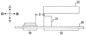
- FIG. 4 is an external view of the top, front, and side surfaces of the vehicle-mounted antenna device.
- FIG. 3 is a schematic diagram illustrating a structural example of an antenna unit of the vehicle-mounted antenna device.
- FIG. 2 is a side view, a top view, a front view, and a perspective view of a lateral element which is a first example of the capacitive loading element.
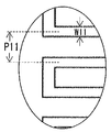
- FIG. 4 is a partially enlarged view of a broken line part in FIG. 3.
- FIG. 3 is an explanatory diagram for defining a direction and an elevation angle as viewed from a patch antenna.
- FIG. 4 is a side view of the lateral element according to the first embodiment and the lateral element according to Modification 1 in which the pitch is changed.
- FIG. 7 is a diagram illustrating a pitch-gain characteristic for each elevation angle of a patch antenna using the pitch of a lateral element as a parameter.
- FIG. 9 is a diagram illustrating a line width-gain characteristic for each elevation angle of a patch antenna using the line width of a lateral element as a parameter.
- FIG. 10 is a side view of the lateral element according to the embodiment and the lateral element according to Modification 2 in which the length in the front-rear direction is changed.
- FIG. 9 is an explanatory diagram of the length-gain characteristics of the patch antenna for each elevation angle, using the length of the lateral element in the front-rear direction as a parameter.
- FIG. 7 is an explanatory diagram of a maximum and minimum gain difference of the patch antenna at an elevation angle of 0 degree of the patch antenna using the length of the lateral element in the front-back direction as a parameter.
- FIG. 7 is a side view, a top view, a front view, and a perspective view of a vertical element according to a second embodiment of the capacitive loading element.
- FIG. 7 is a diagram illustrating a pitch-gain characteristic for each elevation angle of a patch antenna using the pitch of a vertical element as a parameter.
- FIG. 6 is a diagram illustrating frequency-gain characteristics of a patch antenna when a vertical element is present and when a comparative example element is present.
- the side view perspective view which shows the modification of 1st Example.
- FIG. 1 is an external view of an upper surface, a front surface, and a side surface of a vehicle-mounted antenna device according to an embodiment of the present invention.
- This in-vehicle antenna device is installed, for example, on a vehicle roof.
- the forward direction of the vehicle is referred to as “front” or “forward”
- the opposite direction is referred to as “rear” or “rearward”.
- the right side in the forward direction of the vehicle is referred to as “right” or “right direction”
- the left side in the forward direction is referred to as "left” or “left direction”.
- the direction of gravity of the vehicle is referred to as “down” or “down”
- the opposite direction is referred to as "up” or "up”.
- the in-vehicle antenna device includes a case portion 100 made of a synthetic resin having radio wave permeability in which a storage space for storing the antenna portion is formed, and an antenna base portion 30 attachable to a vehicle. Is done.
- the antenna base portion 30 has a substantially elliptical shape, and is mounted such that the central axis in the longitudinal direction is parallel to the traveling direction of the vehicle. That is, the front of the vehicle is in front of the antenna base 30 (the case 100), the rear of the vehicle is behind the antenna base 30 (the case 100), and the width direction of the vehicle is the width of the antenna base 30 (the case 100).
- the case part 100 is formed into a streamlined shape that is thinner and lower toward the front and has a curved side surface inward (toward the central axis in the longitudinal direction), and is fitted on the outer edge of the antenna base part 30. You.
- the length of the case portion 100 in the longitudinal direction is about 180 mm
- the length in the width direction is about 70 mm
- the upper length (height) is about 70 mm.
- the antenna base unit 30 is provided with a capture unit 31 for fixing to the vehicle roof and taking ground.
- FIG. 2 is a schematic diagram showing a structural example of the antenna unit of the vehicle-mounted antenna device.
- the antenna unit includes two elements installed on the antenna base unit 30 apart from each other.
- One element (first element) is a patch antenna 10 that can receive a SDARS (satellite digital audio service: a general term including XM and Sirius) band (first frequency band).
- the patch antenna 10 is a kind of a planar antenna and has a substantially circular polarization characteristic.
- the SDARS band is 2320 MHz to 2345 MHz, and one wavelength of 2332.5 MHz, which is the center frequency of the used (receivable) frequency band (hereinafter sometimes simply referred to as “used frequency”), is about 128 mm.
- the resonance frequency that is, the wavelength of the used frequency is referred to as “resonance length”.
- the resonance length corresponds to an integral multiple of 4 of the wavelength ⁇ of the working frequency. All wavelengths at frequencies other than the resonance frequency have a non-resonance length.
- a resonance type antenna such as an FM antenna or a patch antenna
- the conductor has a non-resonance length, it is impossible to receive a signal at a level to obtain a desired gain.
- another antenna arranged in the same case is configured with the resonance length of the patch antenna 10, the electric characteristics of the patch antenna 10 are affected.
- the other element is the capacity loading element 22.
- the capacitive loading element 22 resonates in the FM wave band when the helical element 21 as an inductor is connected, and becomes a part of the AM / FM antenna 20 that also receives the AM wave band.
- the distance D between the patch antenna 10 and the front end of the capacitive loading element 22 varies depending on the structure of the capacitive loading element 22, but is generally about 20 mm, which is about ⁇ of the wavelength ⁇ of the operating frequency of the patch antenna 10.
- the capacitance loading element 22 is a three-dimensional element that has an upper end (upper edge) and a lower end (lower edge) that are substantially parallel to the antenna base 30.
- the upper end and the lower end are each provided as a pair.
- Each upper end and each lower end face each other via a gap.
- the capacitive loading element 22 is, for example, a pair of linear conductors that repeat turns in a meander shape, and a linear connection in which the capacitive loading element 22 is formed into a three-dimensional shape by coupling these linear conductors. And a conductor.
- the capacity loading element 22 can be the following two types of elements depending on the direction of the turn.
- a pair of linear conductors each repeating a turn in the front-rear direction is connected by a connection conductor extending in the width direction. For example, after the turn is repeated in the front-rear direction and the direction approaching the antenna base 30, the direction is changed in the width direction, and then the turn is repeated in the front-rear direction so as to move away from the antenna base 30.
- a capacity loading element 22 is referred to as a “lateral element” for convenience.
- a pair of linear conductors that repeat turns in the vertical direction are connected by linear connecting conductors extending in the width direction. For example, after a turn is repeated in the vertical direction so as to extend in the forward or rearward direction, the direction is changed in the width direction, and then, the turn in the vertical direction is repeated so as to extend in the opposite direction from before the change in direction.
- the capacity loading element 22 in such an embodiment is referred to as a “longitudinal element” for convenience.
- the capacity loading element 22 is a horizontal element and a vertical element will be described.
- FIG. 3 is a side view, top view, front view, and perspective view of a lateral element.
- FIG. 4 is a partially enlarged view of a broken line portion in FIG.
- the horizontal element 221 is formed by connecting a pair of linear conductors in a meandering shape (hereinafter, referred to as a “meander element”; the same applies hereinafter) 2211 and 2212 by a connecting portion 2213 which is the above-described connecting conductor. It is formed into a three-dimensional shape.
- the length of the turned portion (turned portion) is the non-resonant length of the patch antenna 10.
- the length h1 of one side of the conductor extending in the vertical direction is 8 mm.
- the length L1 in the front-rear direction (the length in the longitudinal direction of the upper end portion and the lower end portion) is 50 mm, and the length of the connecting portion 2213 extending in the width direction is 15 mm. Therefore, the lateral element 221 has no effect on the patch antenna 10 or has little effect.
- the length H1 of each of the meander elements 2211 and 2212 in the vertical direction (the length between the upper end and the lower end) is 30 mm.
- H1 indicates, for example, the length of a specific point in the front-rear direction of the upper end, and the intersection of a virtual line along the shape of the element vertically from the specific point and the virtual line in the front-rear direction of the lower end.
- the length h1 of one side of the conductor extending in the up-down direction of each of the meander elements 2211 and 2212, the length L1 in the front-rear direction, and the length of the connecting portion 2213 are examples, and h1 (the portion where the capacitive loading element 22 turns)
- the length H1, the length L1, and the length of the connecting portion 2213 in the vertical direction can be changed as appropriate.
- the number of turns may be changed as necessary, and the length H1 in the up-down direction may be changed accordingly.
- the length outside the turning portion is h1 and this h1 is a non-resonance length, it is more preferable that the length inside the turning portion also has a non-resonance length.
- the line width W11 of the linear conductor (the outer diameter in the case of the linear conductor) and the pitch P11 of the distance between the center axes of the adjacent linear conductors are different from those of the patch antenna 10 and the AM / AM.
- the line width W11 is about 2 mm and the pitch P11 is about 6 mm.
- the connecting portion 2213 is the same wire as the helical element 21 and the meander elements 2211 and 2212.
- the helical element 21, the meander elements 2211 and 2212, and the connecting portion 2213 have the same cross-sectional shape and outer diameter, and are integrally formed. More specifically, the helical element 21, the meander elements 2211 and 2212, and the connecting portion 2213 are integrally formed from a single wire such as a copper wire.
- the helical element 21, the meander elements 2211 and 2212, and the connecting portion 2213 may be connected independently by soldering or the like.
- the helical element 21, the respective meander elements 2211 and 2212, and the connecting portion 2213 may be formed of wires of the same material, or may be formed of wires of the same cross-sectional shape and outer diameter but different materials. Is also good.
- the helical element 21 as an inductor may be formed of the same member as the meander elements 2211 and 2212 or a linear conductor having the same cross-sectional shape.
- the helical element 21 having the same cross-sectional shape and outer diameter may be connected to each of the meander elements 2211 and 2212 and the connecting portion 2213 formed by processing a metal part such as a sheet metal by soldering or the like.
- the pair of meander elements 2211 and 2212 that repeat the -turn form a symmetrical shape about a plane (virtual plane) orthogonal to the antenna base 30.
- a plane virtual plane
- it is formed in a C shape (a shape in which the lines are separated from each other in the inverted V shape) when viewed from the front.
- the distance from the virtual surface to the pair of upper ends is equal, and the distance from the virtual surface to the pair of lower ends is equal.
- the gap between the pair of lower ends is larger than the gap between the pair of upper ends.
- a metal plate may be arranged between the helical element 21 and the capacity loading element 22, and the helical element 21 and the capacity loading element 22 may be connected via the metal plate by, for example, soldering.
- FIG. 5 is an explanatory diagram for defining the elevation angle as viewed from the patch antenna 10.
- the upward direction is particularly referred to as the “zenith direction”.
- the elevation angle is 90 degrees.
- the elevation angles in the front-rear direction and the width direction are 0 degrees.
- An elevation angle of 0 degrees is for receiving terrestrial waves.
- FIG. 6 is a side view of a lateral element 221 and a lateral element 221 ′ according to a first modification in which the pitch P11 is changed.
- the meander element 2211 'of the horizontal element 221' has the same length (height) H1, vertical length L1, and line width W11 as the meander element 2211 of the embodiment shown in FIG. ,
- the pitch P12 is about 3 mm, which is half of the pitch P11 (about 6 mm).
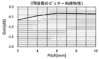
- FIG. 7A is a diagram showing the pitch-gain characteristics of the FM wave band when the pitch of the horizontal element 221 (P11: Pitch: mm) is used as a parameter.
- FIG. 7B is a diagram showing the line width (W11 : Mm) is a diagram showing a line width-gain characteristic of an FM wave band when a parameter is used.
- the gain (average gain: dB) of the lateral element 221 in the FM band increases as the pitch of the meander element 2211 increases and as the line width of the meander element 2211 increases. I do.
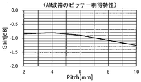
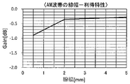
- FIG. 8A is a diagram showing a frequency-gain characteristic of the AM waveband using the pitch (P11: Pitch: mm) of the horizontal element 221 as a parameter
- FIG. 8B is a diagram showing a line width (W11: mm) of the horizontal element 221.
- FIG. 4 is a diagram showing frequency-gain characteristics of an AM waveband with parameters ()).
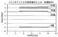
- FIG. 9A is a diagram illustrating a pitch-gain characteristic for each elevation angle of the patch antenna 10 using the pitch (P11: Pitch: mm) of the horizontal element 221 as a parameter
- FIG. FIG. 10 is a diagram illustrating a line width-gain characteristic for each elevation angle of the patch antenna 10 using W11: mm) as a parameter.
- the gain in the zenith direction (elevation angle 90 degrees) (average gain in horizontal plane Gain: dBic) is 4.4 when the pitch P11 of the meander element 2211 is 3 mm, 4.5 at 7.5 mm, and 4.6 at 10 mm.
- the gain (Gain: dBic) at an elevation angle of 60 degrees is 3.9 when the pitch P11 of the meander element 2211 is 3 mm to 10 mm.
- the gain (Gain: dBic) at an elevation angle of 30 degrees is 2.3 when the pitch P11 of the meander element 2211 is 3 mm to 10 mm.
- the elevation angle of 0 degree, that is, the gain in the horizontal direction (Gain: dBic) is -5.9 when the pitch P11 of the meander element 2211 is 3 mm to 10 mm.
- the pitch P11 and the line width W11 of the meander element 2211 have little effect on the gain in the SDARS band, and therefore, the pitch P11 and the line width for optimizing the gain of the AM wave band and the FM wave band. W11 is good.
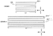
- FIG. 10 is a side view of the lateral element 221 and the lateral element 221 ′′ according to Modification 2 in which the length in the front-rear direction is changed.
- the meander element 2211 ′′ of the lateral element 221 ′′ has the same pitch (P11) and line width (W11) as the meander element 2211 according to the embodiment, but the length L2 in the front-rear direction is the length in the front-rear direction. It differs in that it is longer than L1.
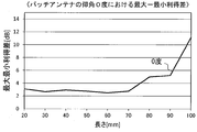
- FIG. 11A is an explanatory diagram of the length-gain characteristics of the patch antenna 10 at each elevation angle using the length of the lateral element 221 in the front-rear direction as a parameter.
- FIG. 11B is the maximum and minimum of the patch antenna 10 at the elevation angle of 0 degree.
- FIG. 4 is an explanatory diagram of a gain difference.
- the elevation angle of 0 degree is the front-rear direction and the width direction on a plane parallel to the antenna base 30.
- the gain at an elevation angle of 90 degrees (average gain in horizontal plane Gain: dBic) is 5.7 at 20 mm in the front-rear direction, 5.6 at 30 mm, 3.2 at 40 mm, 4.0 at 50 mm, and 4.0 at 60 mm. It is 4.9 at 5, 70 mm, 4.8 at 80 mm, 4.9 at 90 mm, and 5.2 at 100 mm. That is, it is substantially constant between 60 mm and 90 mm.
- the maximum / minimum gain difference at an elevation angle of 0 ° increases sharply when the length of the lateral element 221 in the front-rear direction is 90 mm or more. This length corresponds to about 3 of one wavelength of the working frequency of the SDARS waveband. Therefore, it is desirable that the length in the front-rear direction be set to a value other than the resonance length of the patch antenna 10 and not to exceed 90 mm. Even if the length in the front-rear direction is, for example, about 40 mm, the performance required in actual use is satisfied. Therefore, the length in the front-rear direction should be considered in optimizing the gain of the AM wave band and the FM wave band. Is enough.
- the inventors of the present application created a comparative example element in order to clarify the difference in the configuration and the operation and effect between the lateral element 221 having the configuration according to the first embodiment and the element disclosed in Patent Document 1.
- the antenna characteristics were simulated.
- the capacitive loading element 22 was formed into an umbrella shape having the shape and size shown in the side, top, front, and perspective appearance views of FIG. Things.
- the entire comparative example antenna is referred to as an “umbrella-shaped element”.
- the umbrella-shaped element 225 has a three-dimensional shape in which a pair of inclined portions 2251 and 252 continuously extend from a top portion 2253, as shown in the front and perspective structures in FIG. 12, and only the lower end portion is open.
- the inclined portions 2251 and 2252 have the same shape and size, and have a length L1 in the front-rear direction, a length H1 in the up-down direction, a point symmetrical with respect to a plane (virtual plane) orthogonal to the antenna base, and a virtual shape.
- the gradient with respect to the plane is the same as that of the lateral element 221 according to the first embodiment.
- the material, thickness, and the like are the same as those of the lateral element 221.
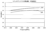
- FIG. 13 shows a comparison example of the frequency-gain characteristics of the patch antenna 10 when the lateral element 221 is present in the capacitive loading element 22 according to the first embodiment and when the umbrella element 225 is present.
- the horizontal axis in FIG. 13 is the frequency (2320 MHz to 2345 MHz) of the SDARS band, and the vertical axis is the average gain (dBic) in the horizontal plane at an elevation angle of 90 degrees.
- the solid line shows the characteristic when the horizontal element 221 is present, and the broken line shows the characteristic when the umbrella element 225 is present.
- the gain (dBic) of the patch antenna 10 is 3.51 at 2320 MHz in the low band, 3.98 at 2332.5 MHz of the used frequency, and 4.04 at 2345 MHz in the high band. .
- the gain (dBic) of the patch antenna 10 is 4.03 at 2320 MHz in the low band, 4.49 at 2332.5 MHz of the used frequency, and 449 at 2345 MHz in the high band. .70.
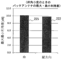
- FIG. 14A is a diagram illustrating a comparative example of the maximum / minimum gain difference (dB) of the patch antenna 10 at the used frequency (2332.5 MHz) in the SDARS band when the elevation angle is 0 degree
- FIG. FIG. 5 is a diagram illustrating a comparative example of the directivity characteristics of the patch antenna 10;
- the scale (0 to -20) of the directivity characteristic is a circular polarization gain (dBic), and the upper part of the figure is the front direction and the lower part of the figure is the rear direction.
- the maximum / minimum gain difference (dB) of the patch antenna 10 is 10.1 when the capacitive loading element 22 is the umbrella-shaped element 225, and is reduced to 2.5 when the capacitive element 22 is the lateral element 221.
- the gain in the width direction (left-right direction) is sharply reduced, whereas in the case of the horizontal element 221, the gain is obtained evenly in almost all directions. I understand. That is, when the lateral element 221 is used as the capacity loading element 22, the effect of reducing the maximum / minimum gain difference of the terrestrial wave is remarkably excellent.
- the effect regarding the maximum / minimum gain difference will be described in detail. If the length h1 of one side of the conductor extending in the vertical direction in the capacitive loading element 22 is the resonance length of the SDARS band, a vertical current is generated in the capacitive loading element 22. At this time, the directional characteristics become maximum in the front-back direction (horizontal direction) of the capacity loading element 22. This causes interference with the terrestrial (horizontal) directional characteristics of the patch antenna 10 and increases the maximum / minimum gain difference.
- the umbrella-shaped element 225 has a length h1 of 30 mm.
- the conductor has a meander structure in which the length h1 of one side of the conductor extending in the vertical direction is turned back so as not to be the resonance length of the SDARS band.
- the length h1 is about 8 mm. That is, the linear conductor of the capacitive loading element 22 repeats the turn in the front-rear direction of the antenna base portion, and the vertical length of the turned portion of the linear conductor is the non-resonant length of the patch antenna 10.
- the length h1 is the non-resonant length in the SDARS band, no vertical current is generated, and the terrestrial directivity of the patch antenna 10 is not affected.
- FIG. 15 is an external view of the side, top, front, and perspective views of the vertical element.
- the vertical element 222 is formed into a three-dimensional shape by connecting a pair of meander elements 2221 and 2222 with a connecting portion 2223 that is a connecting conductor.
- the vertical element 222 differs from the horizontal element 221 of the first embodiment only in the direction of the turn of the linear conductor, and has a length L1 in the front-rear direction, a length (H1) in the vertical direction, a line width, a pitch, and the like. ,
- the length H1 of each of the meander elements 2221 and 2222 in the vertical direction 222 is 30 mm.
- the length of the turned portion is the non-resonant length of the patch antenna 10.
- the length l1 of one side of the conductor extending in the front-rear direction at the portion where the capacitive loading element 22 turns is 8 mm.
- the length of the connecting portion 2223 is 15 mm, and each is the non-resonant length of the patch antenna 10. Therefore, the vertical element 222 has no effect on the patch antenna 10 or has little effect.
- the length L1 of each meander element 2221, 2222 in the front-rear direction is 50 mm.
- the length l1 of one side of the meander elements 2222 and 2222 extending in the front-rear direction and the length of the connecting portion 2223 are examples, and l1 (one side of the conductor extending in the front-rear direction in the portion where the capacitive loading element 22 turns) Is the non-resonant length of the patch antenna 10, the length H1 in the up-down direction, the length L1 in the front-rear direction, and the length of the connecting portion 2223 can be changed as appropriate. For example, the number of turns may be changed as necessary, and the length L1 in the front-rear direction may be changed accordingly.
- the length outside the turning portion is assumed to be l1 and this l1 is a non-resonance length, it is more preferable that the length inside the turning portion also has a non-resonance length.
- FIG. 16 is a side view of a vertical element 222 and a vertical element 222 ′ according to a third modification in which the pitch P21 of 6 mm is changed to the pitch P22 of 3 mm.
- FIG. 17 is a diagram illustrating a gain characteristic of the patch antenna 10 at each elevation angle using the pitch P21 of the vertical element 222 as a parameter.
- the gain in the zenith direction (elevation angle 90 degrees) (average gain in the horizontal plane Gain: dBic) is 5.5 when the pitch P21 of the vertical element 222 is 3 mm, 5.5 when the pitch is 5 mm, 5.6 and 7.5 mm when the pitch 6 mm is 6 mm.
- the gain at an elevation angle of 60 degrees (average gain in the horizontal plane Gain: dBic) is 4.5 at 5 mm, 4.5 at 6 mm, 4.5 at 6 mm, 4.5 at 7.5 mm, and 4.6 at 10 mm. It is.
- the gain at an elevation angle of 30 degrees (average gain in horizontal plane Gain: dBic) is 2.0 at 5 mm, 1.9 at 5 mm, 1.9 at 6 mm, 1.9 at 7.5 mm, 1.8 at 7.5 mm. It is.
- the gain at an elevation angle of 0 degree (average gain in horizontal plane Gain: dBic) is as follows: pitch P21 is -5.5 at 3 mm, -5.5 at 5 mm, -5.5 at 6 mm, -5.5 at 6 mm, -5.5, 10 mm at 7.5 mm Is -5.6. That is, also in the case of the vertical element 222, the pitch P21 has a small effect on the gain in the SDARS band, so that the pitch P21 that optimizes the gain in the AM wave band and the FM wave band is sufficient.
- FIG. 18 shows a comparison diagram of the frequency-gain characteristics of the patch antenna 10 when the vertical element 222 exists and when the umbrella element 225 exists.
- the horizontal axis of FIG. 18 indicates the frequency (2320 MHz to 2345 MHz) of the SDARS band, and the vertical axis indicates the average gain (dBic) in the horizontal plane at an elevation angle of 90 degrees.
- the solid line indicates the characteristic in the case of the vertical element 222, and the broken line indicates the characteristic in the case of the umbrella element 225.
- the gain (dBic) of the patch antenna 10 is 3.51 at 2320 MHz in the low band, 3.98 at 2332.5 MHz of the used frequency, and 4.04 at 2345 MHz in the high band. This is as described in the first embodiment.
- the gain (dBic) of the patch antenna 10 is 5.23 at 2320 MHz in the low band, 5.56 at 2332.5 MHz of the used frequency, and 556 at 2345 MHz in the high band. .51.
- the gain at the elevation angle of 90 degrees is improved over the entire frequency band.
- FIG. 19A is a diagram illustrating a comparative example of the maximum / minimum gain difference (dB) of the patch antenna 10 at the operating frequency (2332.5 MHz) in the SDARS band when the elevation angle is 0 degree
- FIG. FIG. 9 is a diagram illustrating a comparative example of the directivity characteristics of the antenna 10.
- the scale (0 to -20) of the directivity characteristic is a circular polarization gain (dBic), and the upper part of the figure is the front direction and the lower part of the figure is the rear direction.
- the maximum / minimum gain difference (dB) of the patch antenna 10 is 10.1 in the case of the umbrella-shaped element 225, and 9.8 in the vertical element 222, which are almost the same.
- the length l1 of one side of the conductor extending in the front-rear direction in the capacitive loading element 22 is the resonance length of the SDARS band
- a longitudinal current is generated in the capacitive loading element 22.
- the directional characteristics are maximum in the vertical direction (vertical direction) of the capacitive loading element 22. This causes interference with the directional characteristics of the patch antenna 10 in the vertical direction.
- a meander structure is formed by folding back so that the length l1 of one side of the conductor extending in the front-rear direction does not become the resonance length of the SDARS band.
- the length 11 is about 8 mm.
- the linear conductor of the capacitive loading element 22 repeats the vertical turn of the antenna base portion, and the length of the turned portion of the linear conductor in the front-rear direction is the non-resonant length of the patch antenna 10.
- the length 11 is the non-resonant length of the SDARS band, no current is generated in the front-rear direction, and the directivity of the patch antenna 10 in the vertical direction is not affected.
- the antenna unit having the horizontal element 221 according to the first embodiment (the former) and the antenna unit including the vertical element 222 according to the second embodiment (the latter) are substantially equivalent in the FM wave band and the AM wave band. It has been found that gain can be obtained. That is, the gain (average gain: dB) in the FM wave band is -0.35 for the former and -0.44 for the latter. The gain (average gain: dB) of the AM waveband at 500 kHz is -0.95 for the former and -0.81 for the latter.
- the meander element (horizontal element 221 or vertical element 222) is used as the capacitive loading element 22, the degree of coupling with the patch antenna 10 is reduced, and interference is further suppressed. Is done.
- the horizontal element 221 has a remarkable effect of reducing the elevation angle of 0 degree, that is, the maximum / minimum gain difference of the terrestrial wave
- the vertical element 222 has a remarkable effect of improving the gain in the zenith direction. Therefore, the horizontal element 221 and the vertical element 222 can be used properly according to the application.
- the length H1 in the vertical direction, the front and rear The length L1 in the direction and the length of the connecting portion 2213 may be the resonance length of the patch antenna 10.
- the length H1 in the vertical direction and the length of the connecting portion 2213 may be the resonance length of the patch antenna 10, but may be the resonance length of the patch antenna 10.
- the vertical length H1 The length L1 in the front-back direction and the length of the connecting portion 2213 may be the resonance length.
- the length L1 in the front-rear direction and the length of the connecting portion 2223 may be the resonance length of the patch antenna 10, but the vertical length L1 may be the resonance length of the patch antenna 10.
- the terrestrial directional characteristics of the patch antenna 10 can be improved.
- the vertical length H1, the front-back length L1, and the length of the connecting portion 2213 may be the non-resonant length.
- the length H1, the length L1 in the front-rear direction, and the length of the connecting portion 2213 may be the non-resonance length.
- the capacitance loading element 22 is such that at least one of the length of each of the pair of upper ends or the pair of lower ends and the length between the upper and lower ends is the non-resonant length of the patch antenna 10. There may be.
- the capacitance loading element 22 has a three-dimensional shape having a pair of upper ends and a pair of lower ends opposed to each other with a gap therebetween, and the length of each of the pair of upper ends or the pair of lower ends, and Since at least one of the lengths between the upper end and the lower end is the non-resonant length of the patch antenna 10, even when the capacitive loading element 22 exists near the patch antenna 10, mutual interference is suppressed.
- the capacity loading element 22 (the meander elements 2211 and 2212 and the connecting portion 2213 or the meander elements 2221 and 2222 and the connecting portion 2223) and the helical element 21 have the same cross-sectional shape and outer shape.
- the embodiments are not limited to this.
- the capacity loading element 22 and the helical element 21 may be different in at least one of the cross-sectional shape and the outer shape.
- FIG. 20 is a side perspective view showing a modification of the first embodiment.
- FIG. 20 shows an example of the lateral element 221.
- the meander elements 2211 and 2212 and the connecting portion 2213 are linear conductors formed by processing metal parts of the same material, and are fixed to the resin holder 22a.
- the helical element 21 is configured by winding one conductor wire around a resin holder 21a.
- the meander elements 2211 and 2212 and the connecting portion 2213 and the helical element 21 have different cross-sectional shapes and outer shapes.
- the connecting portion 2213 is provided with a structure that can tie one end of the helical element. For example, at a portion C in FIG.
- the capacity loading element 22 and the helical element 21 are electrically connected by soldering or the like. Also in such a modification, the length of each of the pair of upper ends or the pair of lower ends of the lateral element 221 is the non-resonant length of the patch antenna 10. The vertical length of the turning portion of the horizontal element 221 is the non-resonant length of the patch antenna 10.
- the vertical element 222 has a similar structure.
- the meander elements 2221 and 2222 and the connecting portion 2223 are linear conductors formed by processing metal parts of the same material, and are fixed to the resin holder 22a.
- the helical element 21 is configured by winding one conductor wire around the resin holder 21a.
- the meander elements 2221 and 2222 and the connecting portion 2223 and the helical element 21 have different cross-sectional shapes and outer shapes.
- the length of each of the pair of upper ends or the pair of lower ends of the vertical element 222 is the non-resonant length of the patch antenna 10.
- the length in the front-rear direction of the turning portion of the vertical element 222 is the non-resonant length of the patch antenna 10.
- the length of the upper end portion and the lower end portion of the capacitive loading element 22 is set to 3/4 or less of the wavelength ⁇ of the operating frequency of the patch antenna 10 has been described.
- the directional element 222 it can be less than 1 / of the wavelength ⁇ of the working frequency.
- the element may have a planar shape, a net shape, a fractal shape, or a zigzag shape.
- at least one of the length in the front-rear direction of the upper end, the length in the front-rear direction of the lower end, and the length between the upper end and the lower end of the capacitive loading element 22 is the non-resonance of the first antenna. Long.
- the meander element may be formed on a surface of a resin holder having a surface. In this way, the length in the horizontal direction and the length in the vertical direction can be reduced by the amount of the dielectric constant.
- a pattern such as a horizontal element, a vertical element, a net-like element, a fractal element, or a zigzag element is formed on the surface of the holder using a conductive paint.
- the shape of the holder may be a rectangular parallelepiped, a cube, or another shape.
- the example of the patch antenna 10 for receiving the SDARS band has been described as an example of the first antenna.
- the first antenna may be a frequency band other than the AM wave band and the FM wave band, for example, GNSS. (Global Navigation Satellite System) Other types of antennas that receive signals in the band may be used.
- the capacitive loading element 22 using the meander element is a horizontal element or a vertical element has been described, but the embodiment is not limited to this.
- the linear conductor in the capacitive loading element 22 may have a region that repeats a turn in the front-rear direction and a region that repeats a turn in the vertical direction.
- the capacitive loading element 22 has been described as having a shape in which the upper and lower ends of the three-dimensional element are open, the present invention can also be applied to an element in which the upper end of the three-dimensional element is not open. is there. That is, the capacity loading element 22 may be an umbrella-shaped element having a top. In such a case, the umbrella-shaped capacity loading element 22 has at least one of a length in the front-rear direction of the upper edge, a length in the front-rear direction of the lower edge, and a length between the upper edge and the lower edge. Is the non-resonant length of the first antenna.
Landscapes
- Engineering & Computer Science (AREA)
- Remote Sensing (AREA)
- Physics & Mathematics (AREA)
- Electromagnetism (AREA)
- Variable-Direction Aerials And Aerial Arrays (AREA)
- Waveguide Aerials (AREA)
- Details Of Aerials (AREA)
Abstract
互いに異なる周波数帯の信号を受信する複数のアンテナが近接する場合の干渉を抑制することができる車載アンテナ装置を提供する。 車両に取付可能なアンテナベース部30上に、互いに離れて設置されるパッチアンテナ10と容量装荷エレメント22とを有する。容量装荷エレメント22は、パッチアンテナ10と異なる使用周波数帯を受信可能なアンテナの一部となって、所定方向のターンを繰り返す一対の線状導体がアンテナベース部30の幅方向に延びる線状の連結導体で連結された立体状をなし容量装荷エレメント22において、線状導体の折り返し部分の長さは、パッチアンテナ10の非共振長である。
Description
本発明は、低背型の車載アンテナ装置に関する。
低背型の車載用アンテナ装置として、特許文献1に開示されたアンテナ装置が知られている。このアンテナ装置は、アンテナベース上に立設された絶縁性のエレメントホルダーと、エレメントホルダーの上部に固着されている傘型エレメントと、傘型エレメントと共にアンテナ部を構成するコイルとを備えている。傘型エレメントは、第1の傾斜部と頂部及び第2の傾斜部と頂部がそれぞれ連続する板状の導体であり、面積をできるだけ大きくすることで、利得が高くなるようにしている。
特許文献1に開示されているアンテナ装置は、傘型エレメントが板状で、かつ、第1の傾斜部と頂部及び第2の傾斜部と頂部がそれぞれ連続している。そのため、共通ケース内に配置される他アンテナのエレメントのアンテナ特性に影響を与えてしまうという問題がある。特に、パッチアンテナのような略円偏波で高周波の信号を受信するアンテナの場合は、傘型エレメントとの干渉による利得低下や水平面内指向性の最大最小利得差が大きくなる。
本発明は、他アンテナエレメントの利得低下や水平面内指向性の最大最小利得差の増加を抑制する車載アンテナ装置を提供することを主たる課題とする。
本発明は、他アンテナエレメントの利得低下や水平面内指向性の最大最小利得差の増加を抑制する車載アンテナ装置を提供することを主たる課題とする。
本発明の第1の態様に係る車載アンテナ装置は、車両に取付可能なアンテナベース部と、前記アンテナベース部上に互いに離れて設置される第1エレメントと第2エレメントとを有し、前記第1エレメントは、第1周波数帯用の第1アンテナであり、前記第2エレメントは、前記第1周波数帯と異なる第2周波数帯用の第2アンテナの一部となって、所定方向のターンを繰り返す一対の線状導体が前記アンテナベース部の幅方向に延びる線状の連結導体で連結された立体状をなし、前記第2エレメントにおいて、前記線状導体の折り返し部分の長さは、前記第1アンテナの非共振長であることを特徴とする。
また、本発明の第2の態様に係る車載アンテナ装置は、車両に取付可能なアンテナベース部と、前記アンテナベース部上に、互いに離れて設置される第1エレメントと第2エレメントとを有し、前記第1エレメントは、第1周波数帯用の第1アンテナであり、前記第2エレメントは、前記第1周波数帯と異なる第2周波数帯用の第2アンテナの一部となって、上縁部及び下縁部を有し、前記上縁部の前後方向の長さ、前記下縁部の前後方向の長さ、及び、前記上縁部と前記下縁部との間の上下方向の長さの少なくとも一つの長さが前記第1アンテナの非共振長であることを特徴とする。
また、本発明の第2の態様に係る車載アンテナ装置は、車両に取付可能なアンテナベース部と、前記アンテナベース部上に、互いに離れて設置される第1エレメントと第2エレメントとを有し、前記第1エレメントは、第1周波数帯用の第1アンテナであり、前記第2エレメントは、前記第1周波数帯と異なる第2周波数帯用の第2アンテナの一部となって、上縁部及び下縁部を有し、前記上縁部の前後方向の長さ、前記下縁部の前後方向の長さ、及び、前記上縁部と前記下縁部との間の上下方向の長さの少なくとも一つの長さが前記第1アンテナの非共振長であることを特徴とする。
本発明の上記態様によれば、第1アンテナと第2アンテナとの干渉が抑制されるので、第1アンテナ部の利得低下や水平面内指向性の最大最小利得差の増加を抑制することができる。
以下、図面を参照して本発明の実施の形態例を説明する。
図1は、本発明の一実施形態に係る車載アンテナ装置の上面、正面、側面の外観図である。
この車載アンテナ装置は、例えば車両ルーフに設置される。これらの図において、車両の前進方向を「前」又は「前方」、その反対方向を「後」又は「後方」といい、両者を区別する必要がない場合は「長手方向」という。また、車両の前進方向右側を「右」又は「右方向」、前進方向左側を「左」又は「左方向」といい、両者を区別する必要がない場合は「幅方向」という。また、車両の重力方向を「下」又は「下方」、その反対方向を「上」又は「上方」という。
図1は、本発明の一実施形態に係る車載アンテナ装置の上面、正面、側面の外観図である。
この車載アンテナ装置は、例えば車両ルーフに設置される。これらの図において、車両の前進方向を「前」又は「前方」、その反対方向を「後」又は「後方」といい、両者を区別する必要がない場合は「長手方向」という。また、車両の前進方向右側を「右」又は「右方向」、前進方向左側を「左」又は「左方向」といい、両者を区別する必要がない場合は「幅方向」という。また、車両の重力方向を「下」又は「下方」、その反対方向を「上」又は「上方」という。
本実施形態の車載アンテナ装置は、アンテナ部を収納するための収納空間が形成されている電波透過性を有する合成樹脂製のケース部100と、車両に取付可能なアンテナベース部30を備えて構成される。アンテナベース部30は、略楕円状であり、長手方向の中心軸線が車両の進行方向と平行になるように取り付けられる。つまり、車両の前方はアンテナベース部30(ケース部100)の前方、車両の後方はアンテナベース部30(ケース部100)の後方、車両の幅方向はアンテナベース部30(ケース部100)の幅方向となる。ケース部100は、前方へ向かうほど細くかつ低くなると共に、側面も内側に(長手方向の中心軸線に向かって)湾曲した曲面とされた流線型に成形され、アンテナベース部30の外縁に被嵌される。ケース部100の長手方向の長さは約180mm、幅方向の長さは約70mm、上方の長さ(高さ)は約70mmである。アンテナベース部30には、車両ルーフへ固定しつつグランドを取るためのキャプチャ部31が設けられている。
図2は、車載アンテナ装置のアンテナ部の構造例を示す模式図である。アンテナ部は、アンテナベース部30上に互いに離れて設置される二つのエレメントを含んで構成される。一つのエレメント(第1エレメント)は、SDARS(衛星デジタルオーディオサービス:XMやSiriusを含めた総称)帯(第1周波数帯)を受信可能なパッチアンテナ10である。パッチアンテナ10は、平面アンテナの一種であり、略円偏波特性をもつ。SDARS帯は、2320MHz~2345MHzであり、使用(受信可能な)周波数帯の中心周波数(以下、単に「使用周波数」という場合がある。)である2332.5MHzの1波長は約128mmである。共振周波数すなわち使用周波数の波長を「共振長」という。共振長は、使用周波数の波長λの1/4の整数倍が該当する。共振周波数以外の周波数の波長は全て非共振長となる。FMアンテナやパッチアンテナのような共振型アンテナの場合、導体の長さが非共振長では所望の利得を得るレベルの信号の受信ができない。また、同一ケース内に配置される他のアンテナがパッチアンテナ10の共振長で構成されている場合、パッチアンテナ10の電気特性に影響を及ぼす。
もう一つのエレメント(第2エレメント)は、容量装荷エレメント22である。容量装荷エレメント22は、インダクタとしてのヘリカルエレメント21が接続されることによりFM波帯で共振し、AM波帯も受信するAM/FMアンテナ20の一部となる。パッチアンテナ10と容量装荷エレメント22の前端との距離Dは、容量装荷エレメント22の構造によっても異なるが、概ね、パッチアンテナ10の使用周波数の波長λの約1/6となる約20mmである。
容量装荷エレメント22は、アンテナベース部30と略平行な上端部(上縁部)及び下端部(下縁部)が開口する立体状をなすエレメントである。上端部と下端部は、それぞれ一対ずつ存在する。各上端部及び各下端部は、それぞれ間隙を介して対向する。
より具体的には、容量装荷エレメント22は、例えばメアンダ状にターンを繰り返す一対の線状導体と、これらの線状導体を連結することにより容量装荷エレメント22を立体状となす、線状の連結導体と、で構成する。
容量装荷エレメント22は、ターンの方向によって以下の2種類の態様のエレメントとすることができる。一つの態様の容量装荷エレメント22は、それぞれ前後方向のターンを繰り返す一対の線状導体が幅方向に延びる連結導体で連結されている。例えば、前後方向かつアンテナベース部30に近づく方向にターンを繰り返した後、幅方向に向きを変え、その後にアンテナベース部30から遠ざかるように前後方向にターンを繰り返す。このような態様の容量装荷エレメント22を便宜上「横方向エレメント」と称する。
より具体的には、容量装荷エレメント22は、例えばメアンダ状にターンを繰り返す一対の線状導体と、これらの線状導体を連結することにより容量装荷エレメント22を立体状となす、線状の連結導体と、で構成する。
容量装荷エレメント22は、ターンの方向によって以下の2種類の態様のエレメントとすることができる。一つの態様の容量装荷エレメント22は、それぞれ前後方向のターンを繰り返す一対の線状導体が幅方向に延びる連結導体で連結されている。例えば、前後方向かつアンテナベース部30に近づく方向にターンを繰り返した後、幅方向に向きを変え、その後にアンテナベース部30から遠ざかるように前後方向にターンを繰り返す。このような態様の容量装荷エレメント22を便宜上「横方向エレメント」と称する。
もう一つの態様の容量装荷エレメント22は、それぞれ上下方向(上端部及び下端部の方向)にターンを繰り返す一対の線状導体が、幅方向に延びる線状の連結導体で連結されている。例えば、前方向又は後方向に延びるように上下方向にターンを繰り返した後、幅方向に向きを変え、その後に向きを変える前と反対方向に延びるように、上下方向のターンを繰り返す。このような態様の容量装荷エレメント22を便宜上「縦方向エレメント」と称する。以下、容量装荷エレメント22を横方向エレメント及び縦方向エレメントとした場合の実施例を説明する。
[第1実施例]
まず、容量装荷エレメント22の第1実施例について説明する。第1実施例は、横方向エレメントの例である。図3は、横方向エレメントの側面、上面、正面、斜視の外観図である。図4は、図3の破線部分の部分拡大図である。
横方向エレメント221は、一対の線状導体を例えばメアンダ状にターンしたエレメント(「メアンダエレメント」と称する。以下同じ)2211,2212が、上記の連結導体である連結部2213で連結されることで立体状に成形される。
ここで、容量装荷エレメント22において、ターンする部分(折り返し部分)の長さは、パッチアンテナ10の非共振長である。具体的には、容量装荷エレメント22がターンする部分において、上下方向に延びる導体の一辺の長さh1は8mmである。前後方向の長さ(上端部及び下端部の長手方向の長さ)L1は50mm、幅方向に延びる連結部2213の長さは15mmで、いずれもパッチアンテナ10の非共振長である。そのため、横方向エレメント221がパッチアンテナ10に与える影響は無いか、あっても小さいものとなる。このとき、各メアンダエレメント2211,2212の上下方向の長さ(上端部と下端部との間の長さ)H1は30mmである。H1は、例えば、上端部の前後方向における特定の一点と、その特定の一点から上下方向にエレメントの形状に沿う仮想線及び下端部の前後方向の仮想線の交点との長さを示す。なお、各メアンダエレメント2211,2212の上下方向に延びる導体の一辺の長さh1、前後方向の長さL1、及び連結部2213の長さは一例であり、h1(容量装荷エレメント22がターンする部分において、上下方向に延びる導体の一辺の長さ)がパッチアンテナ10の非共振長であれば上下方向の長さH1、前後方向の長さL1及び連結部2213の長さは、適宜変更可能である。例えば、折返し数を必要に応じて変えても良いし、それに応じて上下方向の長さH1が変化しても良い。なお、ターンする部分の外側の長さをh1としこのh1が非共振長であるものとして説明したが、ターンする部分の内側の長さも非共振長とすることがより望ましい。
まず、容量装荷エレメント22の第1実施例について説明する。第1実施例は、横方向エレメントの例である。図3は、横方向エレメントの側面、上面、正面、斜視の外観図である。図4は、図3の破線部分の部分拡大図である。
横方向エレメント221は、一対の線状導体を例えばメアンダ状にターンしたエレメント(「メアンダエレメント」と称する。以下同じ)2211,2212が、上記の連結導体である連結部2213で連結されることで立体状に成形される。
ここで、容量装荷エレメント22において、ターンする部分(折り返し部分)の長さは、パッチアンテナ10の非共振長である。具体的には、容量装荷エレメント22がターンする部分において、上下方向に延びる導体の一辺の長さh1は8mmである。前後方向の長さ(上端部及び下端部の長手方向の長さ)L1は50mm、幅方向に延びる連結部2213の長さは15mmで、いずれもパッチアンテナ10の非共振長である。そのため、横方向エレメント221がパッチアンテナ10に与える影響は無いか、あっても小さいものとなる。このとき、各メアンダエレメント2211,2212の上下方向の長さ(上端部と下端部との間の長さ)H1は30mmである。H1は、例えば、上端部の前後方向における特定の一点と、その特定の一点から上下方向にエレメントの形状に沿う仮想線及び下端部の前後方向の仮想線の交点との長さを示す。なお、各メアンダエレメント2211,2212の上下方向に延びる導体の一辺の長さh1、前後方向の長さL1、及び連結部2213の長さは一例であり、h1(容量装荷エレメント22がターンする部分において、上下方向に延びる導体の一辺の長さ)がパッチアンテナ10の非共振長であれば上下方向の長さH1、前後方向の長さL1及び連結部2213の長さは、適宜変更可能である。例えば、折返し数を必要に応じて変えても良いし、それに応じて上下方向の長さH1が変化しても良い。なお、ターンする部分の外側の長さをh1としこのh1が非共振長であるものとして説明したが、ターンする部分の内側の長さも非共振長とすることがより望ましい。
図4に示すように、線状導体の幅(線導体の場合は外径)である線幅W11と、隣り合う線状導体の中心軸間の距離であるピッチP11がパッチアンテナ10とAM/FMアンテナ20に与える影響については後述するが、図3の例では、線幅W11が約2mm、ピッチP11は約6mmである。
連結部2213は、ヘリカルエレメント21及び各メアンダエレメント2211,2212と同じ線材である。例えば、ヘリカルエレメント21、各メアンダエレメント2211,2212及び連結部2213は、断面形状及び外径は同じであり、一体に構成されている。より具体的には、ヘリカルエレメント21、各メアンダエレメント2211,2212及び連結部2213は、1本の銅線等の線材から一体的に構成される。
ヘリカルエレメント21、各メアンダエレメント2211,2212及び連結部2213は、それぞれ独立に構成されたものを半田付け等によって連結しても良い。かかる場合、ヘリカルエレメント21、各メアンダエレメント2211,2212及び連結部2213は、同じ材質の線材から各々構成されても良いし、断面形状及び外径が同じであり材質が異なる線材から各々構成されても良い。例えば、インダクタとしてのヘリカルエレメント21は、メアンダエレメント2211、2212と同じ部材又は同じ断面形状の線状導体で構成されてもよい。また、板金などの金属部品を加工して構成された各メアンダエレメント2211,2212及び連結部2213に、断面形状及び外径が同じであるヘリカルエレメント21を半田付け等によって連結しても良い。
ターンを繰り返す一対のメアンダエレメント2211,2212は、アンテナベース部30と直交する面(仮想面)を中心として対称の形状をなす。例えば、正面から見てハ字状(逆V字状のうち線が互いに離間している形状)に成形されている。この場合、仮想面から一対の上端部までの距離が等しく、かつ、仮想面から一対の下端部までの距離が等しい。また、一対の上端部間の間隙よりも一対の下端部間の間隙の方が大きいものとなっている。これにより、ヘリカルエレメント21に所定の容量を装荷することができる。
ヘリカルエレメント21と容量装荷エレメント22との間に金属プレートを配置し、たとえば半田付けなどで金属プレートを介して、ヘリカルエレメント21と容量装荷エレメント22を接続しても良い。
図5は、パッチアンテナ10から見た仰角を定義するための説明図である。車載アンテナ装置から見て上下方向のうち上方向を特に「天頂方向」と呼ぶ。天頂方向は、仰角が90度である。前後方向及び幅方向の仰角は0度となる。仰角が0度は、地上波の受信用となる。
横方向エレメント221は、様々なパターンで形成することができる。例えば図6は、横方向エレメント221とそのピッチP11を変更した変形例1に係る横方向エレメント221’の側面図である。横方向エレメント221’のメアンダエレメント2211’は、上下方向の長さ(高さ)H1、前後方向の長さL1、線幅W11は図3に示した実施例のメアンダエレメント2211と同じであるが、ピッチP12が上記のピッチP11(約6mm)の半分の約3mmとなっている。
図7Aは、横方向エレメント221のピッチ(P11:Pitch:mm)をパラメータとしたときのFM波帯のピッチ-利得特性を示す図であり、図7Bは、横方向エレメント221の線幅(W11:mm)をパラメータとしたときのFM波帯の線幅-利得特性を示す図である。これらの図から判るように、横方向エレメント221のFM波帯における利得(平均利得Gain:dB)は、メアンダエレメント2211のピッチが大きくなるにつれて、また、メアンダエレメント2211の線幅が大きくなるにつれて向上する。
図7Aは、横方向エレメント221のピッチ(P11:Pitch:mm)をパラメータとしたときのFM波帯のピッチ-利得特性を示す図であり、図7Bは、横方向エレメント221の線幅(W11:mm)をパラメータとしたときのFM波帯の線幅-利得特性を示す図である。これらの図から判るように、横方向エレメント221のFM波帯における利得(平均利得Gain:dB)は、メアンダエレメント2211のピッチが大きくなるにつれて、また、メアンダエレメント2211の線幅が大きくなるにつれて向上する。
図8Aは、横方向エレメント221のピッチ(P11:Pitch:mm)をパラメータとしたAM波帯の周波数-利得特性を示す図であり、図8Bは、横方向エレメント221の線幅(W11:mm)をパラメータとしたAM波帯の周波数-利得特性を示す図である。これらの図から判るように、横方向エレメント221のAM波帯における利得(平均利得Gain:dB)は、メアンダエレメント2211のピッチが小さくなるにつれて大きくなる。また、メアンダエレメント2211の線幅が大きくなるにつれて利得が向上する。
図9Aは、横方向エレメント221のピッチ(P11:Pitch:mm)をパラメータとしたパッチアンテナ10の仰角毎のピッチ-利得特性を示す図であり、図9Bは、横方向エレメント221の線幅(W11:mm)をパラメータとしたパッチアンテナ10の仰角毎の線幅-利得特性を示す図である。天頂方向(仰角90度)の利得(水平面内平均利得Gain:dBic)は、メアンダエレメント2211のピッチP11が3mmの場合4.4、7.5mmで4.5、10mmで4.6である。仰角60度の利得(Gain:dBic)は、メアンダエレメント2211のピッチP11が3mm~10mmのいずれの場合も3.9である。仰角30度の利得(Gain:dBic)は、メアンダエレメント2211のピッチP11が3mm~10mmのいずれの場合も2.3である。仰角0度すなわち水平方向の利得(Gain:dBic)は、メアンダエレメント2211のピッチP11が3mm~10mmのいずれの場合も-5.9である。
つまり、横方向エレメント221の場合、SDARS帯では、メアンダエレメント2211のピッチP11及び線幅W11が利得に与える影響は小さいので、AM波帯及びFM波帯の利得を最適化するピッチP11及び線幅W11であれば良いことになる。
図10は、横方向エレメント221とその前後方向の長さを変更した変形例2に係る横方向エレメント221’’の側面図である。横方向エレメント221’’のメアンダエレメント2211’’は、ピッチ(P11)、線幅(W11)は実施例に係るメアンダエレメント2211と同じであるが、前後方向の長さL2が前後方向の長さL1よりも長い点で異なる。
図11Aは、横方向エレメント221の前後方向の長さをパラメータとしたパッチアンテナ10の仰角毎の長さ-利得特性の説明図であり、図11Bは、仰角0度におけるパッチアンテナ10の最大最小利得差の説明図である。仰角0度は、アンテナベース部30と平行の平面における前後方向及び幅方向である。仰角90度の利得(水平面内平均利得Gain:dBic)は、前後方向の長さが20mmで5.7、30mmで5.6、40mmで3.2、50mmで4.0、60mmで4.5、70mmで4.9、80mmで4.8、90mmで4.9、100mmで5.2である。つまり、60mmから90mmの間でほぼ一定となる。
また、仰角0度の最大最小利得差は、横方向エレメント221の前後方向の長さが90mm以上で急激に大きくなる。この長さは、SDARS波帯の使用周波数の1波長の約3/4に相当する。そのため、前後方向の長さは、パッチアンテナ10の共振長以外で、かつ、90mmを超えないように設定することが望ましい。なお、前後方向の長さが例えば約40mmであっても、実使用上の要求性能は満たすことから、前後方向の長さについては、AM波帯及びFM波帯の利得の最適化を考慮すれば足りる。
<比較例エレメントとの比較>
本願発明者らは、第1実施例に係る構成の横方向エレメント221と、特許文献1に開示されているエレメントとの構成及び作用効果の相違を明確にするため、比較例エレメントを作成してそのアンテナ特性をシミュレーションした。比較例エレメントは、図2に示したアンテナ部の配置を維持した状態で、容量装荷エレメント22を図12の側面、上面、正面、斜視の外観図に示した形状・サイズの傘型に成形したものである。便宜上、比較例アンテナ全体を「傘型エレメント」と称する。
本願発明者らは、第1実施例に係る構成の横方向エレメント221と、特許文献1に開示されているエレメントとの構成及び作用効果の相違を明確にするため、比較例エレメントを作成してそのアンテナ特性をシミュレーションした。比較例エレメントは、図2に示したアンテナ部の配置を維持した状態で、容量装荷エレメント22を図12の側面、上面、正面、斜視の外観図に示した形状・サイズの傘型に成形したものである。便宜上、比較例アンテナ全体を「傘型エレメント」と称する。
傘型エレメント225は、図12の正面及び斜視の構造に示される通り、一対の傾斜部2251,2252が頂部2253から連続に延びる立体状であり、下端部のみが開口している。傾斜部2251,2252は同じ形状及びサイズであり、その前後方向の長さL1、上下方向の長さH1、アンテナベース部と直交する面(仮想面)を中心として対称の形状である点、仮想面に対する勾配などは、第1実施例に係る横方向エレメント221と同じである。材質、厚みなども横方向エレメント221と同じである。
第1実施例に係る容量装荷エレメント22に横方向エレメント221が存在する場合と傘型エレメント225が存在する場合のパッチアンテナ10の周波数-利得特性の比較例を図13に示す。図13の横軸はSDARS帯の周波数(2320MHz~2345MHz)、縦軸は仰角90度の水平面内平均利得(dBic)である。実線は横方向エレメント221が存在する場合の特性、破線は傘型エレメント225が存在する場合の特性を示す。
傘型エレメント225が存在する場合、パッチアンテナ10の利得(dBic)は、低域の2320MHzで3.51、使用周波数の2332.5MHzで、3.98、高域の2345MHzで4.04である。これに対して横方向エレメント221が存在する場合、パッチアンテナ10の利得(dBic)は、低域の2320MHzで4.03、使用周波数の2332.5MHzで、4.49、高域の2345MHzで4.70である。このように、パッチアンテナ10の近くに存在する容量装荷エレメント22が横方向エレメント221の場合は、傘型エレメント225の場合よりも、全周波数帯にわたって仰角90度における利得が向上することが判る。
図14Aは、仰角0度のときのSDARS帯の使用周波数(2332.5MHz)におけるパッチアンテナ10の最大最小利得差(dB)の比較例を示した図であり、図14Bは、仰角0度におけるパッチアンテナ10の指向特性の比較例を示した図である。指向特性の目盛り(0~-20)は円偏波利得(dBic)であり、図上部が前方向、図下部が後方向である。パッチアンテナ10の最大最小利得差(dB)は、容量装荷エレメント22が傘型エレメント225の場合は10.1であるのに対し、横方向エレメント221の場合は2.5まで小さくなっている。また、指向特性は、傘型エレメント225の場合、幅方向(左右方向)の利得が急激に低下するのに対し、横方向エレメント221の場合は、ほぼ全方向にわたって均等に利得が得られることが判る。
つまり、容量装荷エレメント22として横方向エレメント221を用いた場合、地上波の最大最小利得差を低減させる効果が格段に優れることが判る。
つまり、容量装荷エレメント22として横方向エレメント221を用いた場合、地上波の最大最小利得差を低減させる効果が格段に優れることが判る。
上記最大最小利得差に関する効果について詳しく説明する。容量装荷エレメント22において上下方向に延びる導体の一辺の長さh1がSDARS帯の共振長である場合、容量装荷エレメント22には上下方向の電流が発生する。このとき、指向特性は、容量装荷エレメント22の前後方向(水平方向)で最大となる。これにより、パッチアンテナ10の地上波(水平方向)指向特性と干渉し、最大最小利得差が増大する。
傘型エレメント225は、長さh1が30mmである。したがってSDARS帯の共振長となるため、傘型エレメント225の前後方向(水平方向)に不要電波が放射され、パッチアンテナ10の地上波指向特性と干渉が生じるために最大最小利得差が増大する。
第1実施例では、上下方向に延びる導体の一辺の長さh1がSDARS帯の共振長にならないよう折り返してメアンダ構造にしている。このとき上記長さh1は約8mmである。すなわち、容量装荷エレメント22の線状導体は、それぞれアンテナベース部の前後方向のターンを繰り返し、線状導体において、ターンする部分の上下方向の長さは、パッチアンテナ10の非共振長である。このように、第1実施例では上記長さh1がSDARS帯の非共振長であるため、上下方向の電流が発生せず、パッチアンテナ10の地上波指向特性へ影響を与えることがない。
傘型エレメント225は、長さh1が30mmである。したがってSDARS帯の共振長となるため、傘型エレメント225の前後方向(水平方向)に不要電波が放射され、パッチアンテナ10の地上波指向特性と干渉が生じるために最大最小利得差が増大する。
第1実施例では、上下方向に延びる導体の一辺の長さh1がSDARS帯の共振長にならないよう折り返してメアンダ構造にしている。このとき上記長さh1は約8mmである。すなわち、容量装荷エレメント22の線状導体は、それぞれアンテナベース部の前後方向のターンを繰り返し、線状導体において、ターンする部分の上下方向の長さは、パッチアンテナ10の非共振長である。このように、第1実施例では上記長さh1がSDARS帯の非共振長であるため、上下方向の電流が発生せず、パッチアンテナ10の地上波指向特性へ影響を与えることがない。
[第2実施例]
次に、容量装荷エレメント22の第2実施例について説明する。第2実施例は、縦方向エレメントの例である。図15は、縦方向エレメントの側面、上面、正面、斜視の外観図である。縦方向エレメント222は、一対のメアンダエレメント2221,2222が、連結導体である連結部2223で連結されることで立体状に成形されている。縦方向エレメント222は、線状導体のターンの方向が第1実施例の横方向エレメント221と違うだけで、前後方向の長さL1、上下方向の長さ(H1)、線幅、ピッチなどは、横方向エレメント221と同じである。
次に、容量装荷エレメント22の第2実施例について説明する。第2実施例は、縦方向エレメントの例である。図15は、縦方向エレメントの側面、上面、正面、斜視の外観図である。縦方向エレメント222は、一対のメアンダエレメント2221,2222が、連結導体である連結部2223で連結されることで立体状に成形されている。縦方向エレメント222は、線状導体のターンの方向が第1実施例の横方向エレメント221と違うだけで、前後方向の長さL1、上下方向の長さ(H1)、線幅、ピッチなどは、横方向エレメント221と同じである。
すなわち、縦方向エレメント222も、各メアンダエレメント2221,2222の上下方向の長さH1は30mmである。ここで、容量装荷エレメント22において、ターンする部分の長さは、パッチアンテナ10の非共振長である。具体的には、容量装荷エレメント22がターンする部分において前後方向に延びる導体の一辺の長さl1は8mmである。連結部2223の長さは15mmで、いずれもパッチアンテナ10の非共振長である。そのため、縦方向エレメント222がパッチアンテナ10に与える影響は無いか、あっても小さいものとなる。このとき、各メアンダエレメント2221,2222の前後方向の長さL1は50mmである。
なお、各メアンダエレメント2221,2222の前後方向に延びる一辺の長さl1、及び連結部2223の長さは一例であり、l1(容量装荷エレメント22がターンする部分において、前後方向に延びる導体の一辺の長さ)がパッチアンテナ10の非共振長であれば上下方向の長さH1、前後方向の長さL1及び連結部2223の長さは、適宜変更可能である。例えば、折返し数を必要に応じて変えても良いし、それに応じて前後方向の長さL1が変化しても良い。なお、ターンする部分の外側の長さをl1としこのl1が非共振長であるものとして説明したが、ターンする部分の内側の長さも非共振長とすることがより望ましい。
なお、各メアンダエレメント2221,2222の前後方向に延びる一辺の長さl1、及び連結部2223の長さは一例であり、l1(容量装荷エレメント22がターンする部分において、前後方向に延びる導体の一辺の長さ)がパッチアンテナ10の非共振長であれば上下方向の長さH1、前後方向の長さL1及び連結部2223の長さは、適宜変更可能である。例えば、折返し数を必要に応じて変えても良いし、それに応じて前後方向の長さL1が変化しても良い。なお、ターンする部分の外側の長さをl1としこのl1が非共振長であるものとして説明したが、ターンする部分の内側の長さも非共振長とすることがより望ましい。
縦方向エレメント222もまた、様々なパターンで形成することができる。例えば、図16は、縦方向エレメント222とその6mmのピッチP21を3mmのピッチP22に変更した変形例3に係る縦方向エレメント222’の側面図である。また、図17は、縦方向エレメント222のピッチP21をパラメータとしたパッチアンテナ10の仰角毎の利得特性を示す図である。
天頂方向(仰角90度)の利得(水平面内平均利得Gain:dBic)は、縦方向エレメント222のピッチP21が3mmの場合5.5、5mmで5.5、6mmで5.6、7.5mmで5.5、10mmで5.8である。仰角60度の利得(水平面内平均利得Gain:dBic)は、ピッチP21が3mmで4.5、5mmで4.5、6mmで4.5、7.5mmで4.5、10mmで4.6である。仰角30度の利得(水平面内平均利得Gain:dBic)は、ピッチP21が3mmで2.0、5mmで1.9、6mmで1.9、7.5mmで1.9、10mmで1.8である。仰角0度の利得(水平面内平均利得Gain:dBic)は、ピッチP21が3mmで-5.5、5mmで-5.5、6mmで-5.5、7.5mmで-5.5、10mmで-5.6である。
つまり、縦方向エレメント222の場合も、SDARS帯では、ピッチP21が利得に与える影響は小さいので、AM波帯及びFM波帯の利得を最適化するピッチP21であれば良いことになる。
天頂方向(仰角90度)の利得(水平面内平均利得Gain:dBic)は、縦方向エレメント222のピッチP21が3mmの場合5.5、5mmで5.5、6mmで5.6、7.5mmで5.5、10mmで5.8である。仰角60度の利得(水平面内平均利得Gain:dBic)は、ピッチP21が3mmで4.5、5mmで4.5、6mmで4.5、7.5mmで4.5、10mmで4.6である。仰角30度の利得(水平面内平均利得Gain:dBic)は、ピッチP21が3mmで2.0、5mmで1.9、6mmで1.9、7.5mmで1.9、10mmで1.8である。仰角0度の利得(水平面内平均利得Gain:dBic)は、ピッチP21が3mmで-5.5、5mmで-5.5、6mmで-5.5、7.5mmで-5.5、10mmで-5.6である。
つまり、縦方向エレメント222の場合も、SDARS帯では、ピッチP21が利得に与える影響は小さいので、AM波帯及びFM波帯の利得を最適化するピッチP21であれば良いことになる。
<比較例エレメントとの比較>
縦方向エレメント222のアンテナ特性を上記の比較例エレメント(図12に示した傘型エレメント225)と比較する。縦方向エレメント222が存在する場合と傘型エレメント225が存在する場合のパッチアンテナ10の周波数-利得特性比較図を図18に示す。図18の横軸はSDARS帯の周波数(2320MHz~2345MHz)、縦軸は仰角90度の水平面内平均利得(dBic)である。実線は縦方向エレメント222の場合の特性、破線は傘型エレメント225の場合の特性を示す。
縦方向エレメント222のアンテナ特性を上記の比較例エレメント(図12に示した傘型エレメント225)と比較する。縦方向エレメント222が存在する場合と傘型エレメント225が存在する場合のパッチアンテナ10の周波数-利得特性比較図を図18に示す。図18の横軸はSDARS帯の周波数(2320MHz~2345MHz)、縦軸は仰角90度の水平面内平均利得(dBic)である。実線は縦方向エレメント222の場合の特性、破線は傘型エレメント225の場合の特性を示す。
傘型エレメント225が存在する場合、パッチアンテナ10の利得(dBic)は、低域の2320MHzで3.51、使用周波数の2332.5MHzで、3.98、高域の2345MHzで4.04であることは、第1実施例で説明した通りである。
これに対して縦方向エレメント222が存在する場合のパッチアンテナ10の利得(dBic)は、低域の2320MHzで5.23、使用周波数の2332.5MHzで、5.56、高域の2345MHzで5.51である。このように、縦方向エレメント222の場合、全周波数帯にわたって仰角90度における利得が向上することが判る。
これに対して縦方向エレメント222が存在する場合のパッチアンテナ10の利得(dBic)は、低域の2320MHzで5.23、使用周波数の2332.5MHzで、5.56、高域の2345MHzで5.51である。このように、縦方向エレメント222の場合、全周波数帯にわたって仰角90度における利得が向上することが判る。
図19Aは、仰角0度のときのSDARS帯の使用周波数(2332.5MHz)におけるパッチアンテナ10の最大最小利得差(dB)の比較例を示す図であり、図19Bは、仰角0度におけるパッチアンテナ10の指向特性の比較例を示す図である。指向特性の目盛り(0~-20)は円偏波利得(dBic)であり、図上部が前方向、図下部が後方向である。パッチアンテナ10の最大最小利得差(dB)は、傘型エレメント225の場合は10.1で、縦方向エレメント222は9.8でほぼ同等である。
容量装荷エレメント22において前後方向に延びる導体の一辺の長さl1がSDARS帯の共振長である場合、容量装荷エレメント22には前後方向の電流が発生する。このとき、指向特性は、容量装荷エレメント22の上下方向(垂直方向)で最大となる。これにより、パッチアンテナ10の垂直方向の指向特性と干渉する。
第2実施例では、前後方向に延びる導体の一辺の長さl1がSDARS帯の共振長にならないよう折り返してメアンダ構造にしている。このときの上記長さl1は約8mmである。すなわち、容量装荷エレメント22の線状導体は、それぞれアンテナベース部の上下方向のターンを繰り返し、線状導体において、ターンする部分の前後方向の長さは、パッチアンテナ10の非共振長である。このように、長さl1がSDARS帯の非共振長であるため、前後方向の電流が発生せず、パッチアンテナ10の垂直方向の指向特性へ影響を与えることがない。
第2実施例では、前後方向に延びる導体の一辺の長さl1がSDARS帯の共振長にならないよう折り返してメアンダ構造にしている。このときの上記長さl1は約8mmである。すなわち、容量装荷エレメント22の線状導体は、それぞれアンテナベース部の上下方向のターンを繰り返し、線状導体において、ターンする部分の前後方向の長さは、パッチアンテナ10の非共振長である。このように、長さl1がSDARS帯の非共振長であるため、前後方向の電流が発生せず、パッチアンテナ10の垂直方向の指向特性へ影響を与えることがない。
[FM波帯及びAM波帯の特性について]
第1実施例に係る横方向エレメント221を有するアンテナ部(前者)と、第2実施例に係る縦方向エレメント222を有するアンテナ部(後者)は、FM波帯及びAM波帯において、ほぼ同等の利得が得られることが判明している。すなわち、FM波帯における利得(平均利得Gain:dB)は、前者が-0.35、後者が-0.44である。また、AM波帯の500kHzでの利得(平均利得Gain:dB)は、前者が-0.95、後者が-0.81である。
第1実施例に係る横方向エレメント221を有するアンテナ部(前者)と、第2実施例に係る縦方向エレメント222を有するアンテナ部(後者)は、FM波帯及びAM波帯において、ほぼ同等の利得が得られることが判明している。すなわち、FM波帯における利得(平均利得Gain:dB)は、前者が-0.35、後者が-0.44である。また、AM波帯の500kHzでの利得(平均利得Gain:dB)は、前者が-0.95、後者が-0.81である。
[実施形態による効果]
以上の説明の通り、本実施形態では、容量装荷エレメント22としてメアンダエレメント(横方向エレメント221又は縦方向エレメント222)を用いたので、パッチアンテナ10との結合の度合いも小さくなり、干渉がさらに抑制される。
また、横方向エレメント221では仰角0度すなわち地上波の最大最小利得差を低減させる効果が顕著であり、縦方向エレメント222では、天頂方向の利得を向上させる効果が顕著となる。そのため、用途に応じて横方向エレメント221と縦方向エレメント222とを使い分けることができる。
以上の説明の通り、本実施形態では、容量装荷エレメント22としてメアンダエレメント(横方向エレメント221又は縦方向エレメント222)を用いたので、パッチアンテナ10との結合の度合いも小さくなり、干渉がさらに抑制される。
また、横方向エレメント221では仰角0度すなわち地上波の最大最小利得差を低減させる効果が顕著であり、縦方向エレメント222では、天頂方向の利得を向上させる効果が顕著となる。そのため、用途に応じて横方向エレメント221と縦方向エレメント222とを使い分けることができる。
横方向エレメント221の場合、h1(容量装荷エレメント22がターンする部分において、上下方向に延びる導体の一辺の長さ)がパッチアンテナ10の非共振長であれば、上下方向の長さH1、前後方向の長さL1及び連結部2213の長さは、パッチアンテナ10の共振長であっても良い。そして、横方向エレメント221のh1がパッチアンテナ10の非共振長である場合、上下方向の長さH1及び連結部2213の長さは、パッチアンテナ10の共振長であっても良いが、前後方向の長さL1もパッチアンテナ10の非共振長とすることでパッチアンテナ10の垂直方向の指向特性を改善することができる。
また、縦方向エレメント222の場合、l1(容量装荷エレメント22がターンする部分において、前後方向に延びる導体の一辺の長さ)がパッチアンテナ10の非共振長であれば、上下方向の長さH1、前後方向の長さL1及び連結部2213の長さは、共振長であっても良い。そして、縦方向エレメント222のl1がパッチアンテナ10の非共振長である場合、前後方向の長さL1及び連結部2223の長さは、パッチアンテナ10の共振長であっても良いが、上下方向の長さH1もパッチアンテナ10の非共振長とすることでパッチアンテナ10の地上波指向特性を改善することができる。
なお、横方向エレメント221のh1がパッチアンテナ10の非共振長である場合、上下方向の長さH1、前後方向の長さL1及び連結部2213の長さを非共振長としてもよい。また、縦方向エレメント222のl1がパッチアンテナ10の非共振長である場合、上下方向の長さH1、前後方向の長さL1及び連結部2213の長さを非共振長としてもよい。
すなわち、容量装荷エレメント22は、一対の上端部又は一対の下端部の各々の長さ、及び、上端部及び下端部との間の各々の長さの少なくとも一方がパッチアンテナ10の非共振長であるようにしてもよい。このように、容量装荷エレメント22が、それぞれ間隙を介して対向する一対の上端部及び一対の下端部を有する立体状をなし、一対の上端部又は一対の下端部の各々の長さ、及び、上端部及び下端部との間の各々の長さの少なくとも一方がパッチアンテナ10の非共振長なので、パッチアンテナ10の近くに容量装荷エレメント22が存在しても、相互の干渉が抑制される。
また、縦方向エレメント222の場合、l1(容量装荷エレメント22がターンする部分において、前後方向に延びる導体の一辺の長さ)がパッチアンテナ10の非共振長であれば、上下方向の長さH1、前後方向の長さL1及び連結部2213の長さは、共振長であっても良い。そして、縦方向エレメント222のl1がパッチアンテナ10の非共振長である場合、前後方向の長さL1及び連結部2223の長さは、パッチアンテナ10の共振長であっても良いが、上下方向の長さH1もパッチアンテナ10の非共振長とすることでパッチアンテナ10の地上波指向特性を改善することができる。
なお、横方向エレメント221のh1がパッチアンテナ10の非共振長である場合、上下方向の長さH1、前後方向の長さL1及び連結部2213の長さを非共振長としてもよい。また、縦方向エレメント222のl1がパッチアンテナ10の非共振長である場合、上下方向の長さH1、前後方向の長さL1及び連結部2213の長さを非共振長としてもよい。
すなわち、容量装荷エレメント22は、一対の上端部又は一対の下端部の各々の長さ、及び、上端部及び下端部との間の各々の長さの少なくとも一方がパッチアンテナ10の非共振長であるようにしてもよい。このように、容量装荷エレメント22が、それぞれ間隙を介して対向する一対の上端部及び一対の下端部を有する立体状をなし、一対の上端部又は一対の下端部の各々の長さ、及び、上端部及び下端部との間の各々の長さの少なくとも一方がパッチアンテナ10の非共振長なので、パッチアンテナ10の近くに容量装荷エレメント22が存在しても、相互の干渉が抑制される。
[他の変形例]
上述した実施形態では、容量装荷エレメント22(メアンダエレメント2211、2212及び連結部2213、あるいは、メアンダエレメント2221、2222及び連結部2223)と、ヘリカルエレメント21とが断面形状及び外形が同じであるものとして説明したが、実施形態はこれに限定されるものではない。例えば、容量装荷エレメント22と、ヘリカルエレメント21とが、断面形状及び外形の少なくとも一方を異なるようにしても良い。
上述した実施形態では、容量装荷エレメント22(メアンダエレメント2211、2212及び連結部2213、あるいは、メアンダエレメント2221、2222及び連結部2223)と、ヘリカルエレメント21とが断面形状及び外形が同じであるものとして説明したが、実施形態はこれに限定されるものではない。例えば、容量装荷エレメント22と、ヘリカルエレメント21とが、断面形状及び外形の少なくとも一方を異なるようにしても良い。
図20は、第1実施例の変形例を示す側面視透視図である。図20には、横方向エレメント221の例が示されている。横方向エレメント221において、メアンダエレメント2211、2212及び連結部2213は、同じ材質の金属部品を加工して構成された線状導体であり、樹脂ホルダ22aへ固定されている。ヘリカルエレメント21は、1本の導体線を樹脂ホルダ21aに巻き付けて構成されている。
ここで、メアンダエレメント2211、2212及び連結部2213とヘリカルエレメント21とは、異なる断面形状及び外形を有する。そして、連結部2213にはヘリカルエレメントの一端を括り付けることができる構造が設けられている。例えば図20中の部位Cにおいて、半田付けなどにより容量装荷エレメント22とヘリカルエレメント21とが電気的に接続される。このような変形例においても、横方向エレメント221の一対の上端部又は一対の下端部の各々の長さがパッチアンテナ10の非共振長である。また、横方向エレメント221のターンする部分の上下方向の長さは、パッチアンテナ10の非共振長である。
ここで、メアンダエレメント2211、2212及び連結部2213とヘリカルエレメント21とは、異なる断面形状及び外形を有する。そして、連結部2213にはヘリカルエレメントの一端を括り付けることができる構造が設けられている。例えば図20中の部位Cにおいて、半田付けなどにより容量装荷エレメント22とヘリカルエレメント21とが電気的に接続される。このような変形例においても、横方向エレメント221の一対の上端部又は一対の下端部の各々の長さがパッチアンテナ10の非共振長である。また、横方向エレメント221のターンする部分の上下方向の長さは、パッチアンテナ10の非共振長である。
縦方向エレメント222においても同様の構造となる。縦方向エレメント222において、メアンダエレメント2221、2222及び連結部2223は同じ材質の金属部品を加工して構成された線状導体であり、樹脂ホルダ22aへ固定される。
また、ヘリカルエレメント21は、1本の導体線を樹脂ホルダ21aに巻き付けて構成される。そして、メアンダエレメント2221、2222及び連結部2223と、ヘリカルエレメント21とが異なる断面形状及び外形を有する。縦方向エレメント222の一対の上端部又は一対の下端部の各々の長さがパッチアンテナ10の非共振長である。また、縦方向エレメント222のターンする部分の前後方向の長さは、パッチアンテナ10の非共振長である。
また、ヘリカルエレメント21は、1本の導体線を樹脂ホルダ21aに巻き付けて構成される。そして、メアンダエレメント2221、2222及び連結部2223と、ヘリカルエレメント21とが異なる断面形状及び外形を有する。縦方向エレメント222の一対の上端部又は一対の下端部の各々の長さがパッチアンテナ10の非共振長である。また、縦方向エレメント222のターンする部分の前後方向の長さは、パッチアンテナ10の非共振長である。
また、本実施形態では、容量装荷エレメント22の上端部及び下端部の長さが、パッチアンテナ10の使用周波数の波長λの3/4以下とする場合について説明したが、容量装荷エレメント22に縦方向エレメント222を用いる場合、使用周波数の波長λの1/4未満とすることができる。
本実施形態では、また、容量装荷エレメント22としてメアンダエレメントを用いた場合の例について説明したが、それぞれ間隙を介して対向する一対の上端部及び一対の下端部を有する立体状をなす形状、すなわち、立体状のエレメントの上端部及び下端部が開口している形状であれば、面状、網状、フラクタル状、ジグザグ状であっても良い。かかる場合、容量装荷エレメント22は、上端部の前後方向の長さ、下端部の前後方向の長さ、及び、上端部と下端部との間の長さの少なくとも一方が第1アンテナの非共振長である。
また、メアンダエレメントを、面部を有する樹脂製のホルダの面部に形成しても良い。このようにすれば、誘電率の分だけ、水平方向の長さ及び上下方向の長さを短くすることができる。また、そのような樹脂製のホルダを用いる場合、その表面に横方向エレメント、縦方向エレメント、網状エレメント、フラクタルエレメント、ジグザグエレメントなどのパターンを導電性の塗料で形成することにより、容量装荷エレメント22を構成することもできる。なお、ホルダの形状は、直方体や立方体、その他の形状であっても良い。
また、メアンダエレメントを、面部を有する樹脂製のホルダの面部に形成しても良い。このようにすれば、誘電率の分だけ、水平方向の長さ及び上下方向の長さを短くすることができる。また、そのような樹脂製のホルダを用いる場合、その表面に横方向エレメント、縦方向エレメント、網状エレメント、フラクタルエレメント、ジグザグエレメントなどのパターンを導電性の塗料で形成することにより、容量装荷エレメント22を構成することもできる。なお、ホルダの形状は、直方体や立方体、その他の形状であっても良い。
本実施形態では、また、第1アンテナの例としてSDARS帯を受信するパッチアンテナ10の例を説明したが、第1アンテナは、AM波帯及びFM波帯以外の他の周波数帯、例えば、GNSS(Global Navigation Satellite System:全地球航法衛星システム)帯の信号を受信する他の形態のアンテナを用いても良い。
本実施形態では、メアンダエレメントを用いた容量装荷エレメント22として、横方向エレメント又は縦方向エレメントである場合について説明したが、実施形態はこれに限定されるものではない。例えば、容量装荷エレメント22において線状導体は、前後方向にターンを繰り返す領域と、上下方向にターンを繰り返す領域とを有するようにしてもよい。
容量装荷エレメント22は、立体状のエレメントの上端部及び下端部が開口している形状であるものとして説明したが、立体状のエレメントの上端部が開口していない形状のエレメントにも適用可能である。すなわち、容量装荷エレメント22は、頂部を有する傘型のエレメントであってもよい。かかる場合、傘型の容量装荷エレメント22は、上縁部の前後方向の長さ、下縁部の前後方向の長さ、及び、上縁部と下縁部との間の長さの少なくとも一方が第1アンテナの非共振長である。
Claims (15)
- 車両に取付可能なアンテナベース部と、
前記アンテナベース部上に互いに離れて設置される第1エレメントと第2エレメントとを備え、
前記第1エレメントは、第1周波数帯用の第1アンテナであり、
前記第2エレメントは、前記第1周波数帯と異なる第2周波数帯用の第2アンテナの一部となって、所定方向のターンを繰り返す一対の線状導体が前記アンテナベース部の幅方向に延びる線状の連結導体で連結された立体状をなし、
前記第2エレメントにおいて、前記線状導体の折り返し部分の長さは、前記第1アンテナの非共振長である、車載アンテナ装置。 - 前記第2エレメントは、それぞれ前記アンテナベース部の前後方向のターンを繰り返し、
前記第2エレメントにおいて、前記線状導体の折り返し部分の上下方向の長さは、前記第1アンテナの非共振長である、請求項1に記載の車載アンテナ装置。 - 前記第2エレメントは、それぞれ前記アンテナベース部の上下方向のターンを繰り返し、
前記第2エレメントにおいて、前記線状導体の折り返し部分の前後方向の長さは、前記第1アンテナの非共振長である、請求項1に記載の車載アンテナ装置。 - 車両に取付可能なアンテナベース部と、
前記アンテナベース部上に互いに離れて設置される第1エレメントと第2エレメントとを備え、
前記第1エレメントは、第1周波数帯用の第1アンテナであり、
前記第2エレメントは、前記第1周波数帯と異なる第2周波数帯用の第2アンテナの一部となって、上縁部及び下縁部を有し、前記上縁部の前後方向の長さ、前記下縁部の前後方向の長さ、及び、前記上縁部と前記下縁部との間上下方向の長さの少なくとも一つの長さが前記第1アンテナの非共振長である、車載アンテナ装置。 - 前記第2エレメントは、それぞれ間隙を介して対向する一対の前記上縁部及び一対の前記下縁部を有し、それぞれ前記アンテナベース部の前後方向のターンを繰り返す一対の線状導体が前記アンテナベース部の幅方向に延びる線状の連結導体で連結されている、請求項4に記載の車載アンテナ装置。
- 前記第2エレメントにおいて、前記線状導体の折り返し部分の上下方向の長さは、前記第1アンテナの非共振長である、請求項5に記載の車載アンテナ装置。
- 前記第2エレメントは、それぞれ間隙を介して対向する一対の前記上縁部及び一対の前記下縁部を有し、それぞれ前記アンテナベース部の上下方向のターンを繰り返す一対の線状導体が前記アンテナベース部の幅方向に延びる線状の連結導体で連結されている、請求項4に記載の車載アンテナ装置。
- 前記第2エレメントにおいて、前記線状導体の折り返し部分の前後方向の長さは、前記第1アンテナの非共振長である、請求項7に記載の車載アンテナ装置。
- 前記一対の線状導体と前記連結導体とが一体に構成されている、請求項1から3及び5から8のいずれか一項に記載の車載アンテナ装置。
- 前記ターンを繰り返す一対の線状導体が、前記アンテナベース部と直交する面を中心として対称の形状をなす、請求項1から3及び5から9のいずれか一項に記載の車載アンテナ装置。
- 前記上縁部及び前記下縁部の各々の長さが、前記第1アンテナの非共振長で、前記第1アンテナで使用する周波数の波長の3/4以下である、請求項4から8のいずれか一項に記載の車載アンテナ装置。
- 前記第2エレメントが面部を有する樹脂製のホルダの前記面部に形成されている、請求項1から11のいずれか一項に記載の車載アンテナ装置。
- 前記第2アンテナは、前記第2エレメントにインダクタが接続されることでFM波帯で共振し、AM波帯を受信可能である、請求項1から12のいずれか一項に記載の車載アンテナ装置。
- 前記インダクタが前記第2エレメントと同じ部材又は同じ断面形状の線状導体で構成される、請求項13に記載の車載アンテナ装置。
- 前記第1アンテナがパッチアンテナである、請求項1から14のいずれか一項に記載の車載アンテナ装置。
Priority Applications (2)
| Application Number | Priority Date | Filing Date | Title |
|---|---|---|---|
| JP2020527677A JP7293222B2 (ja) | 2018-06-29 | 2019-06-28 | 車載アンテナ装置 |
| US17/253,145 US11509044B2 (en) | 2018-06-29 | 2019-06-28 | Antenna device for vehicle |
Applications Claiming Priority (2)
| Application Number | Priority Date | Filing Date | Title |
|---|---|---|---|
| JP2018124048 | 2018-06-29 | ||
| JP2018-124048 | 2018-06-29 |
Publications (1)
| Publication Number | Publication Date |
|---|---|
| WO2020004612A1 true WO2020004612A1 (ja) | 2020-01-02 |
Family
ID=68986745
Family Applications (1)
| Application Number | Title | Priority Date | Filing Date |
|---|---|---|---|
| PCT/JP2019/025780 Ceased WO2020004612A1 (ja) | 2018-06-29 | 2019-06-28 | 車載アンテナ装置 |
Country Status (4)
| Country | Link |
|---|---|
| US (1) | US11509044B2 (ja) |
| JP (1) | JP7293222B2 (ja) |
| CN (1) | CN210040534U (ja) |
| WO (1) | WO2020004612A1 (ja) |
Cited By (1)
| Publication number | Priority date | Publication date | Assignee | Title |
|---|---|---|---|---|
| WO2023181978A1 (ja) * | 2022-03-25 | 2023-09-28 | 原田工業株式会社 | 低背型複合アンテナ装置 |
Families Citing this family (3)
| Publication number | Priority date | Publication date | Assignee | Title |
|---|---|---|---|---|
| JP6956650B2 (ja) * | 2018-02-19 | 2021-11-02 | 株式会社ヨコオ | 車載用アンテナ装置 |
| WO2021153179A1 (ja) * | 2020-01-28 | 2021-08-05 | 株式会社ヨコオ | 車載用アンテナ装置 |
| WO2022065514A1 (ja) * | 2020-09-28 | 2022-03-31 | 株式会社ヨコオ | 車載用アンテナ装置 |
Citations (2)
| Publication number | Priority date | Publication date | Assignee | Title |
|---|---|---|---|---|
| WO2009004451A2 (en) * | 2007-06-29 | 2009-01-08 | C-Mac Invotronics D/B/A Solectron | Antenna and splitter for receiving radio and remote keyless entry signals |
| WO2018105235A1 (ja) * | 2016-12-06 | 2018-06-14 | 株式会社ヨコオ | アンテナ装置 |
Family Cites Families (3)
| Publication number | Priority date | Publication date | Assignee | Title |
|---|---|---|---|---|
| JP5599098B2 (ja) * | 2010-07-30 | 2014-10-01 | 株式会社ヨコオ | アンテナ装置 |
| JP5654917B2 (ja) | 2011-03-24 | 2015-01-14 | 原田工業株式会社 | アンテナ装置 |
| JP6792406B2 (ja) * | 2016-10-21 | 2020-11-25 | 株式会社ヨコオ | 車載用アンテナ装置 |
-
2019
- 2019-06-28 CN CN201920993164.7U patent/CN210040534U/zh active Active
- 2019-06-28 WO PCT/JP2019/025780 patent/WO2020004612A1/ja not_active Ceased
- 2019-06-28 JP JP2020527677A patent/JP7293222B2/ja active Active
- 2019-06-28 US US17/253,145 patent/US11509044B2/en active Active
Patent Citations (2)
| Publication number | Priority date | Publication date | Assignee | Title |
|---|---|---|---|---|
| WO2009004451A2 (en) * | 2007-06-29 | 2009-01-08 | C-Mac Invotronics D/B/A Solectron | Antenna and splitter for receiving radio and remote keyless entry signals |
| WO2018105235A1 (ja) * | 2016-12-06 | 2018-06-14 | 株式会社ヨコオ | アンテナ装置 |
Cited By (4)
| Publication number | Priority date | Publication date | Assignee | Title |
|---|---|---|---|---|
| WO2023181978A1 (ja) * | 2022-03-25 | 2023-09-28 | 原田工業株式会社 | 低背型複合アンテナ装置 |
| JP2023143344A (ja) * | 2022-03-25 | 2023-10-06 | 原田工業株式会社 | 低背型複合アンテナ装置 |
| JP7498507B2 (ja) | 2022-03-25 | 2024-06-12 | 原田工業株式会社 | 低背型複合アンテナ装置 |
| US12316030B1 (en) | 2022-03-25 | 2025-05-27 | Harada Industry Co., Ltd. | Low-profile composite antenna device |
Also Published As
| Publication number | Publication date |
|---|---|
| US20210273320A1 (en) | 2021-09-02 |
| JP7293222B2 (ja) | 2023-06-19 |
| JPWO2020004612A1 (ja) | 2021-07-15 |
| US11509044B2 (en) | 2022-11-22 |
| CN210040534U (zh) | 2020-02-07 |
Similar Documents
| Publication | Publication Date | Title |
|---|---|---|
| US10249956B2 (en) | Method and apparatus for folded antenna components | |
| JP7293222B2 (ja) | 車載アンテナ装置 | |
| JP6855258B2 (ja) | 複合アンテナ装置 | |
| CA2985852A1 (en) | Patch antenna with peripheral parasitic monopole circular arrays | |
| US11342680B2 (en) | Antenna device | |
| US20220190489A1 (en) | Highly-integrated vehicle antenna configuration | |
| WO2012077389A1 (ja) | アンテナ装置 | |
| JP2003502894A (ja) | 多帯域アンテナ | |
| WO2020075744A1 (ja) | アンテナ、アンテナ装置、および車載用アンテナ装置 | |
| JP6792406B2 (ja) | 車載用アンテナ装置 | |
| JP7224716B2 (ja) | アンテナ装置 | |
| KR101633844B1 (ko) | 차량용 다중대역안테나 | |
| KR20110015407A (ko) | 2주파 안테나 | |
| WO2019027036A1 (ja) | 車載用アンテナ装置 | |
| JP4141979B2 (ja) | 自動車用高周波ガラスアンテナ | |
| JP2020096390A (ja) | アンテナ装置 | |
| EP3154126A1 (en) | Ground phase manipulation in a beam forming antenna | |
| JP4976511B2 (ja) | 円偏波対応アンテナ | |
| EP2355237B1 (en) | Glass antenna and vehicular window glass including the same | |
| JP6923826B2 (ja) | アンテナ及び窓ガラス | |
| JP5162789B2 (ja) | 小形単指向性アンテナ | |
| JP4473113B2 (ja) | 台形型エレメントアンテナ | |
| JP2024027192A (ja) | 車載用アンテナ装置 | |
| JP6440300B2 (ja) | 広帯域アンテナ | |
| JP4024634B2 (ja) | 車両用ガラスアンテナ |
Legal Events
| Date | Code | Title | Description |
|---|---|---|---|
| 121 | Ep: the epo has been informed by wipo that ep was designated in this application |
Ref document number: 19826092 Country of ref document: EP Kind code of ref document: A1 |
|
| ENP | Entry into the national phase |
Ref document number: 2020527677 Country of ref document: JP Kind code of ref document: A |
|
| NENP | Non-entry into the national phase |
Ref country code: DE |
|
| 122 | Ep: pct application non-entry in european phase |
Ref document number: 19826092 Country of ref document: EP Kind code of ref document: A1 |