WO2020004364A1 - Construction machine management system - Google Patents
Construction machine management system Download PDFInfo
- Publication number
- WO2020004364A1 WO2020004364A1 PCT/JP2019/025083 JP2019025083W WO2020004364A1 WO 2020004364 A1 WO2020004364 A1 WO 2020004364A1 JP 2019025083 W JP2019025083 W JP 2019025083W WO 2020004364 A1 WO2020004364 A1 WO 2020004364A1
- Authority
- WO
- WIPO (PCT)
- Prior art keywords
- storage device
- information
- excavator
- power storage
- construction machine
- Prior art date
Links
Images


Classifications
-
- H—ELECTRICITY
- H02—GENERATION; CONVERSION OR DISTRIBUTION OF ELECTRIC POWER
- H02J—CIRCUIT ARRANGEMENTS OR SYSTEMS FOR SUPPLYING OR DISTRIBUTING ELECTRIC POWER; SYSTEMS FOR STORING ELECTRIC ENERGY
- H02J7/00—Circuit arrangements for charging or depolarising batteries or for supplying loads from batteries
- H02J7/0013—Circuit arrangements for charging or depolarising batteries or for supplying loads from batteries acting upon several batteries simultaneously or sequentially
-
- G—PHYSICS
- G01—MEASURING; TESTING
- G01R—MEASURING ELECTRIC VARIABLES; MEASURING MAGNETIC VARIABLES
- G01R31/00—Arrangements for testing electric properties; Arrangements for locating electric faults; Arrangements for electrical testing characterised by what is being tested not provided for elsewhere
- G01R31/36—Arrangements for testing, measuring or monitoring the electrical condition of accumulators or electric batteries, e.g. capacity or state of charge [SoC]
- G01R31/392—Determining battery ageing or deterioration, e.g. state of health
-
- E—FIXED CONSTRUCTIONS
- E02—HYDRAULIC ENGINEERING; FOUNDATIONS; SOIL SHIFTING
- E02F—DREDGING; SOIL-SHIFTING
- E02F9/00—Component parts of dredgers or soil-shifting machines, not restricted to one of the kinds covered by groups E02F3/00 - E02F7/00
- E02F9/20—Drives; Control devices
- E02F9/2058—Electric or electro-mechanical or mechanical control devices of vehicle sub-units
- E02F9/2091—Control of energy storage means for electrical energy, e.g. battery or capacitors
-
- B—PERFORMING OPERATIONS; TRANSPORTING
- B60—VEHICLES IN GENERAL
- B60L—PROPULSION OF ELECTRICALLY-PROPELLED VEHICLES; SUPPLYING ELECTRIC POWER FOR AUXILIARY EQUIPMENT OF ELECTRICALLY-PROPELLED VEHICLES; ELECTRODYNAMIC BRAKE SYSTEMS FOR VEHICLES IN GENERAL; MAGNETIC SUSPENSION OR LEVITATION FOR VEHICLES; MONITORING OPERATING VARIABLES OF ELECTRICALLY-PROPELLED VEHICLES; ELECTRIC SAFETY DEVICES FOR ELECTRICALLY-PROPELLED VEHICLES
- B60L58/00—Methods or circuit arrangements for monitoring or controlling batteries or fuel cells, specially adapted for electric vehicles
- B60L58/10—Methods or circuit arrangements for monitoring or controlling batteries or fuel cells, specially adapted for electric vehicles for monitoring or controlling batteries
- B60L58/12—Methods or circuit arrangements for monitoring or controlling batteries or fuel cells, specially adapted for electric vehicles for monitoring or controlling batteries responding to state of charge [SoC]
-
- E—FIXED CONSTRUCTIONS
- E02—HYDRAULIC ENGINEERING; FOUNDATIONS; SOIL SHIFTING
- E02F—DREDGING; SOIL-SHIFTING
- E02F9/00—Component parts of dredgers or soil-shifting machines, not restricted to one of the kinds covered by groups E02F3/00 - E02F7/00
- E02F9/26—Indicating devices
-
- G—PHYSICS
- G01—MEASURING; TESTING
- G01R—MEASURING ELECTRIC VARIABLES; MEASURING MAGNETIC VARIABLES
- G01R19/00—Arrangements for measuring currents or voltages or for indicating presence or sign thereof
- G01R19/10—Measuring sum, difference or ratio
-
- G—PHYSICS
- G01—MEASURING; TESTING
- G01R—MEASURING ELECTRIC VARIABLES; MEASURING MAGNETIC VARIABLES
- G01R19/00—Arrangements for measuring currents or voltages or for indicating presence or sign thereof
- G01R19/30—Measuring the maximum or the minimum value of current or voltage reached in a time interval
-
- G—PHYSICS
- G01—MEASURING; TESTING
- G01R—MEASURING ELECTRIC VARIABLES; MEASURING MAGNETIC VARIABLES
- G01R31/00—Arrangements for testing electric properties; Arrangements for locating electric faults; Arrangements for electrical testing characterised by what is being tested not provided for elsewhere
- G01R31/36—Arrangements for testing, measuring or monitoring the electrical condition of accumulators or electric batteries, e.g. capacity or state of charge [SoC]
- G01R31/371—Arrangements for testing, measuring or monitoring the electrical condition of accumulators or electric batteries, e.g. capacity or state of charge [SoC] with remote indication, e.g. on external chargers
-
- G—PHYSICS
- G01—MEASURING; TESTING
- G01R—MEASURING ELECTRIC VARIABLES; MEASURING MAGNETIC VARIABLES
- G01R31/00—Arrangements for testing electric properties; Arrangements for locating electric faults; Arrangements for electrical testing characterised by what is being tested not provided for elsewhere
- G01R31/36—Arrangements for testing, measuring or monitoring the electrical condition of accumulators or electric batteries, e.g. capacity or state of charge [SoC]
- G01R31/382—Arrangements for monitoring battery or accumulator variables, e.g. SoC
-
- G—PHYSICS
- G07—CHECKING-DEVICES
- G07C—TIME OR ATTENDANCE REGISTERS; REGISTERING OR INDICATING THE WORKING OF MACHINES; GENERATING RANDOM NUMBERS; VOTING OR LOTTERY APPARATUS; ARRANGEMENTS, SYSTEMS OR APPARATUS FOR CHECKING NOT PROVIDED FOR ELSEWHERE
- G07C5/00—Registering or indicating the working of vehicles
- G07C5/02—Registering or indicating driving, working, idle, or waiting time only
-
- G—PHYSICS
- G08—SIGNALLING
- G08B—SIGNALLING OR CALLING SYSTEMS; ORDER TELEGRAPHS; ALARM SYSTEMS
- G08B21/00—Alarms responsive to a single specified undesired or abnormal condition and not otherwise provided for
- G08B21/18—Status alarms
-
- H—ELECTRICITY
- H01—ELECTRIC ELEMENTS
- H01M—PROCESSES OR MEANS, e.g. BATTERIES, FOR THE DIRECT CONVERSION OF CHEMICAL ENERGY INTO ELECTRICAL ENERGY
- H01M10/00—Secondary cells; Manufacture thereof
- H01M10/42—Methods or arrangements for servicing or maintenance of secondary cells or secondary half-cells
- H01M10/425—Structural combination with electronic components, e.g. electronic circuits integrated to the outside of the casing
-
- H—ELECTRICITY
- H01—ELECTRIC ELEMENTS
- H01M—PROCESSES OR MEANS, e.g. BATTERIES, FOR THE DIRECT CONVERSION OF CHEMICAL ENERGY INTO ELECTRICAL ENERGY
- H01M10/00—Secondary cells; Manufacture thereof
- H01M10/42—Methods or arrangements for servicing or maintenance of secondary cells or secondary half-cells
- H01M10/48—Accumulators combined with arrangements for measuring, testing or indicating the condition of cells, e.g. the level or density of the electrolyte
- H01M10/482—Accumulators combined with arrangements for measuring, testing or indicating the condition of cells, e.g. the level or density of the electrolyte for several batteries or cells simultaneously or sequentially
-
- H—ELECTRICITY
- H02—GENERATION; CONVERSION OR DISTRIBUTION OF ELECTRIC POWER
- H02J—CIRCUIT ARRANGEMENTS OR SYSTEMS FOR SUPPLYING OR DISTRIBUTING ELECTRIC POWER; SYSTEMS FOR STORING ELECTRIC ENERGY
- H02J13/00—Circuit arrangements for providing remote indication of network conditions, e.g. an instantaneous record of the open or closed condition of each circuitbreaker in the network; Circuit arrangements for providing remote control of switching means in a power distribution network, e.g. switching in and out of current consumers by using a pulse code signal carried by the network
- H02J13/00006—Circuit arrangements for providing remote indication of network conditions, e.g. an instantaneous record of the open or closed condition of each circuitbreaker in the network; Circuit arrangements for providing remote control of switching means in a power distribution network, e.g. switching in and out of current consumers by using a pulse code signal carried by the network characterised by information or instructions transport means between the monitoring, controlling or managing units and monitored, controlled or operated power network element or electrical equipment
-
- H—ELECTRICITY
- H02—GENERATION; CONVERSION OR DISTRIBUTION OF ELECTRIC POWER
- H02J—CIRCUIT ARRANGEMENTS OR SYSTEMS FOR SUPPLYING OR DISTRIBUTING ELECTRIC POWER; SYSTEMS FOR STORING ELECTRIC ENERGY
- H02J7/00—Circuit arrangements for charging or depolarising batteries or for supplying loads from batteries
- H02J7/00032—Circuit arrangements for charging or depolarising batteries or for supplying loads from batteries characterised by data exchange
-
- H—ELECTRICITY
- H02—GENERATION; CONVERSION OR DISTRIBUTION OF ELECTRIC POWER
- H02J—CIRCUIT ARRANGEMENTS OR SYSTEMS FOR SUPPLYING OR DISTRIBUTING ELECTRIC POWER; SYSTEMS FOR STORING ELECTRIC ENERGY
- H02J7/00—Circuit arrangements for charging or depolarising batteries or for supplying loads from batteries
- H02J7/0047—Circuit arrangements for charging or depolarising batteries or for supplying loads from batteries with monitoring or indicating devices or circuits
- H02J7/0048—Detection of remaining charge capacity or state of charge [SOC]
-
- B—PERFORMING OPERATIONS; TRANSPORTING
- B60—VEHICLES IN GENERAL
- B60L—PROPULSION OF ELECTRICALLY-PROPELLED VEHICLES; SUPPLYING ELECTRIC POWER FOR AUXILIARY EQUIPMENT OF ELECTRICALLY-PROPELLED VEHICLES; ELECTRODYNAMIC BRAKE SYSTEMS FOR VEHICLES IN GENERAL; MAGNETIC SUSPENSION OR LEVITATION FOR VEHICLES; MONITORING OPERATING VARIABLES OF ELECTRICALLY-PROPELLED VEHICLES; ELECTRIC SAFETY DEVICES FOR ELECTRICALLY-PROPELLED VEHICLES
- B60L2200/00—Type of vehicles
- B60L2200/40—Working vehicles
-
- E—FIXED CONSTRUCTIONS
- E02—HYDRAULIC ENGINEERING; FOUNDATIONS; SOIL SHIFTING
- E02F—DREDGING; SOIL-SHIFTING
- E02F9/00—Component parts of dredgers or soil-shifting machines, not restricted to one of the kinds covered by groups E02F3/00 - E02F7/00
- E02F9/20—Drives; Control devices
- E02F9/22—Hydraulic or pneumatic drives
- E02F9/2221—Control of flow rate; Load sensing arrangements
- E02F9/2225—Control of flow rate; Load sensing arrangements using pressure-compensating valves
- E02F9/2228—Control of flow rate; Load sensing arrangements using pressure-compensating valves including an electronic controller
-
- E—FIXED CONSTRUCTIONS
- E02—HYDRAULIC ENGINEERING; FOUNDATIONS; SOIL SHIFTING
- E02F—DREDGING; SOIL-SHIFTING
- E02F9/00—Component parts of dredgers or soil-shifting machines, not restricted to one of the kinds covered by groups E02F3/00 - E02F7/00
- E02F9/20—Drives; Control devices
- E02F9/22—Hydraulic or pneumatic drives
- E02F9/2278—Hydraulic circuits
- E02F9/2285—Pilot-operated systems
-
- E—FIXED CONSTRUCTIONS
- E02—HYDRAULIC ENGINEERING; FOUNDATIONS; SOIL SHIFTING
- E02F—DREDGING; SOIL-SHIFTING
- E02F9/00—Component parts of dredgers or soil-shifting machines, not restricted to one of the kinds covered by groups E02F3/00 - E02F7/00
- E02F9/20—Drives; Control devices
- E02F9/22—Hydraulic or pneumatic drives
- E02F9/2278—Hydraulic circuits
- E02F9/2296—Systems with a variable displacement pump
-
- H—ELECTRICITY
- H01—ELECTRIC ELEMENTS
- H01M—PROCESSES OR MEANS, e.g. BATTERIES, FOR THE DIRECT CONVERSION OF CHEMICAL ENERGY INTO ELECTRICAL ENERGY
- H01M10/00—Secondary cells; Manufacture thereof
- H01M10/42—Methods or arrangements for servicing or maintenance of secondary cells or secondary half-cells
- H01M10/425—Structural combination with electronic components, e.g. electronic circuits integrated to the outside of the casing
- H01M2010/4271—Battery management systems including electronic circuits, e.g. control of current or voltage to keep battery in healthy state, cell balancing
-
- H—ELECTRICITY
- H01—ELECTRIC ELEMENTS
- H01M—PROCESSES OR MEANS, e.g. BATTERIES, FOR THE DIRECT CONVERSION OF CHEMICAL ENERGY INTO ELECTRICAL ENERGY
- H01M10/00—Secondary cells; Manufacture thereof
- H01M10/42—Methods or arrangements for servicing or maintenance of secondary cells or secondary half-cells
- H01M10/425—Structural combination with electronic components, e.g. electronic circuits integrated to the outside of the casing
- H01M2010/4278—Systems for data transfer from batteries, e.g. transfer of battery parameters to a controller, data transferred between battery controller and main controller
-
- H—ELECTRICITY
- H01—ELECTRIC ELEMENTS
- H01M—PROCESSES OR MEANS, e.g. BATTERIES, FOR THE DIRECT CONVERSION OF CHEMICAL ENERGY INTO ELECTRICAL ENERGY
- H01M2220/00—Batteries for particular applications
- H01M2220/20—Batteries in motive systems, e.g. vehicle, ship, plane
-
- H—ELECTRICITY
- H02—GENERATION; CONVERSION OR DISTRIBUTION OF ELECTRIC POWER
- H02J—CIRCUIT ARRANGEMENTS OR SYSTEMS FOR SUPPLYING OR DISTRIBUTING ELECTRIC POWER; SYSTEMS FOR STORING ELECTRIC ENERGY
- H02J2310/00—The network for supplying or distributing electric power characterised by its spatial reach or by the load
- H02J2310/40—The network being an on-board power network, i.e. within a vehicle
- H02J2310/46—The network being an on-board power network, i.e. within a vehicle for ICE-powered road vehicles
-
- Y—GENERAL TAGGING OF NEW TECHNOLOGICAL DEVELOPMENTS; GENERAL TAGGING OF CROSS-SECTIONAL TECHNOLOGIES SPANNING OVER SEVERAL SECTIONS OF THE IPC; TECHNICAL SUBJECTS COVERED BY FORMER USPC CROSS-REFERENCE ART COLLECTIONS [XRACs] AND DIGESTS
- Y02—TECHNOLOGIES OR APPLICATIONS FOR MITIGATION OR ADAPTATION AGAINST CLIMATE CHANGE
- Y02E—REDUCTION OF GREENHOUSE GAS [GHG] EMISSIONS, RELATED TO ENERGY GENERATION, TRANSMISSION OR DISTRIBUTION
- Y02E60/00—Enabling technologies; Technologies with a potential or indirect contribution to GHG emissions mitigation
- Y02E60/10—Energy storage using batteries
-
- Y—GENERAL TAGGING OF NEW TECHNOLOGICAL DEVELOPMENTS; GENERAL TAGGING OF CROSS-SECTIONAL TECHNOLOGIES SPANNING OVER SEVERAL SECTIONS OF THE IPC; TECHNICAL SUBJECTS COVERED BY FORMER USPC CROSS-REFERENCE ART COLLECTIONS [XRACs] AND DIGESTS
- Y02—TECHNOLOGIES OR APPLICATIONS FOR MITIGATION OR ADAPTATION AGAINST CLIMATE CHANGE
- Y02T—CLIMATE CHANGE MITIGATION TECHNOLOGIES RELATED TO TRANSPORTATION
- Y02T10/00—Road transport of goods or passengers
- Y02T10/60—Other road transportation technologies with climate change mitigation effect
- Y02T10/70—Energy storage systems for electromobility, e.g. batteries
-
- Y—GENERAL TAGGING OF NEW TECHNOLOGICAL DEVELOPMENTS; GENERAL TAGGING OF CROSS-SECTIONAL TECHNOLOGIES SPANNING OVER SEVERAL SECTIONS OF THE IPC; TECHNICAL SUBJECTS COVERED BY FORMER USPC CROSS-REFERENCE ART COLLECTIONS [XRACs] AND DIGESTS
- Y02—TECHNOLOGIES OR APPLICATIONS FOR MITIGATION OR ADAPTATION AGAINST CLIMATE CHANGE
- Y02T—CLIMATE CHANGE MITIGATION TECHNOLOGIES RELATED TO TRANSPORTATION
- Y02T90/00—Enabling technologies or technologies with a potential or indirect contribution to GHG emissions mitigation
- Y02T90/10—Technologies relating to charging of electric vehicles
- Y02T90/16—Information or communication technologies improving the operation of electric vehicles
- Y02T90/167—Systems integrating technologies related to power network operation and communication or information technologies for supporting the interoperability of electric or hybrid vehicles, i.e. smartgrids as interface for battery charging of electric vehicles [EV] or hybrid vehicles [HEV]
-
- Y—GENERAL TAGGING OF NEW TECHNOLOGICAL DEVELOPMENTS; GENERAL TAGGING OF CROSS-SECTIONAL TECHNOLOGIES SPANNING OVER SEVERAL SECTIONS OF THE IPC; TECHNICAL SUBJECTS COVERED BY FORMER USPC CROSS-REFERENCE ART COLLECTIONS [XRACs] AND DIGESTS
- Y04—INFORMATION OR COMMUNICATION TECHNOLOGIES HAVING AN IMPACT ON OTHER TECHNOLOGY AREAS
- Y04S—SYSTEMS INTEGRATING TECHNOLOGIES RELATED TO POWER NETWORK OPERATION, COMMUNICATION OR INFORMATION TECHNOLOGIES FOR IMPROVING THE ELECTRICAL POWER GENERATION, TRANSMISSION, DISTRIBUTION, MANAGEMENT OR USAGE, i.e. SMART GRIDS
- Y04S30/00—Systems supporting specific end-user applications in the sector of transportation
- Y04S30/10—Systems supporting the interoperability of electric or hybrid vehicles
- Y04S30/12—Remote or cooperative charging
Definitions
- the present invention relates to a construction machine management system that manages (grasps and monitors) a construction machine such as a hydraulic shovel, a hydraulic crane, and a wheel loader at a position away from the construction machine.
- a hybrid hydraulic shovel (hybrid shovel) and an electric hydraulic shovel (battery shovel) operate using power stored (charged) in a power storage device as a power source.
- the power storage device is configured to include a storage battery (secondary battery), a control device (BCU), a relay, and the like.
- a storage battery for example, a lithium ion battery is used.
- Storage batteries (lithium-ion batteries) are often used, for example, in the form of an assembled battery that connects a plurality of battery cells (lithium-ion battery cells).
- the lithium ion battery is not preferable for a lithium ion battery to be overcharged or overdischarged. For this reason, it is preferable to use the lithium ion battery while managing it so as not to be in an overcharged or overdischarged state.
- the lithium ion battery is preferably used while monitoring the average remaining charge of the connected battery cells and the maximum and minimum cell voltages of all the battery cells. It is preferable to manage the lithium-ion battery by limiting charging and discharging as necessary and by equalizing (balancing) the voltage (cell voltage) of each battery cell.
- Patent Literature 1 discloses a technique in which the remaining amount of charge of a power storage device is transmitted from a hydraulic shovel to a management device installed outside the hydraulic shovel, and the management device manages the charge. According to the technique of Patent Document 1, the management device estimates the current and future remaining charge from the last received remaining charge, using the self-discharge characteristic data recorded in advance, Output the result.
- Patent Literature 1 does not describe, for example, managing a voltage difference between battery cells when a power storage device is configured by an assembled battery formed by combining a plurality of lithium ion battery cells, that is, a cell voltage difference. .
- the cell voltage difference is a difference (voltage difference) between the maximum value and the minimum value among the voltages (cell voltages) of the plurality of battery cells. That is, the cell voltage difference is the difference between the maximum cell voltage and the minimum cell voltage of all the battery cells used in the battery pack.
- the cell voltage difference occurs due to manufacturing variations of the battery cells.
- the cell voltage difference may increase with the progress of self-discharge during long-term storage because there is a difference in cell capacity (internal resistance) or a difference in cell self-discharge amount.
- the control device that controls the charge and discharge of the power storage device should, for example, always monitor the cell voltage difference during operation and take measures such as limiting the charge and discharge when a voltage difference exceeding a certain level occurs. Is preferred.
- An object of the present invention is to provide a construction machine management system capable of suppressing operation of a construction machine from being restricted due to a voltage difference (cell voltage difference) between a plurality of battery cells constituting a power storage device of the construction machine. It is in.
- the present invention is directed to a management device that is disposed at a position distant from a construction machine having a power storage device and a communication device, receives information on the power storage device transmitted from the construction machine via the communication device, and manages the power storage device.
- the information of the power storage device is information including a maximum value and a minimum value of respective voltages of a plurality of battery cells included in the power storage device, or the plurality of battery cells.
- the management device stores the maximum value, the minimum value, and the discharge characteristics of the power storage device, and is stored in the management device. In addition to the latest maximum value and the minimum value, taking into account the discharge characteristics stored in the management device, a current or future estimated maximum value and an estimated minimum value are calculated, and the calculated estimated maximum value and Previous And outputs the information based on the estimated minimum value.
- the present invention it is possible to suppress the operation of the construction machine from being restricted due to an increase in the voltage difference (cell voltage difference) between the plurality of battery cells constituting the power storage device of the construction machine.
- the management device has information on the power storage device transmitted from the construction machine, specifically, the maximum value and the minimum value of the voltages of the plurality of battery cells constituting the power storage device of the construction machine, or The maximum value and the minimum value of the respective charging rates of the plurality of battery cells are stored. Then, the management device calculates the current or future estimated maximum value and estimated minimum value in consideration of the discharge characteristics in addition to the latest maximum value and minimum value. For this reason, the management device can manage the battery state of the power storage device (for example, the voltage difference between the battery cells and the charging rate difference) even while the construction machine is not operating, based on the estimated maximum value and the estimated minimum value. . That is, the management device can estimate the voltage difference (or charging rate difference) of the battery cells even during long-term suspension, and based on the estimated voltage difference (or charging rate difference), changes the battery state of the power storage device. You can check.
- the management device outputs information based on the estimated maximum value and the estimated minimum value (for example, the estimated voltage difference, the estimated charging rate difference, or the suspension period calculated based on them). Thereby, it can be notified that the voltage difference (or the charging rate difference) between the battery cells is large, that the operation of the construction machine (for example, maintenance operation) is required, and the like. For this reason, based on this output (notification), the manager of the construction machine (for example, the owner, the user, the operator, and the maintenance person) performs construction based on the voltage difference (or charging rate difference) of the battery cells. Before the operation of the machine is restricted or cannot be operated, a countermeasure (for example, a maintenance operation) can be taken. As a result, it is possible to suppress the operation of the construction machine from being restricted or becoming unusable after a long-term suspension of the construction machine.
- a countermeasure for example, a maintenance operation
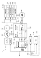
- FIG. 1 is an overall configuration diagram illustrating a construction machine management system including a hydraulic shovel and a management device according to an embodiment.
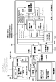
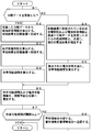
- FIG. 2 is a block diagram illustrating a hydraulic system and an electric system of the hydraulic shovel in FIG. 1. It is a block diagram of the hydraulic shovel and the management apparatus in FIG. 2 is a flowchart illustrating a control process performed by a management server (management device) in FIG. 1.
- FIG. 4 is a characteristic diagram illustrating an example of a cell voltage of a power storage device, a cell voltage difference, warning information, a vehicle suspension possible period, and a time change of daily report reception.
- FIGS. 1 to 5 show an embodiment.
- FIG. 1 shows a hydraulic excavator 1 as a construction machine and a management server 52 as a management device that transmits and receives information (data) to and from the hydraulic excavator 1.
- the hydraulic shovel 1 is a hybrid hydraulic shovel (hybrid shovel) including an engine 11, an assist generator motor 15 (see FIG. 2) as an electric motor, and a power storage device 19 (see FIG. 2). It is configured.
- the management server 52 is installed at a position away from the excavator 1.
- the management server 52 remotely manages (understands and monitors) the state of the excavator 1.
- the construction machine management system includes the management server 52 and the excavator 1.
- the construction machine management system is configured so that bidirectional communication can be performed between the excavator 1 and the management server 52 via the communication line 53 including the wireless communication line 53A. That is, the management server 52 and the remote excavator 1 can transmit and receive information (data) by connecting via the wireless communication line 53A.
- the excavator 1 uses information of the excavator 1 itself (eg, state information of the power storage device 19 and state information of each part of the vehicle body including warning information) as operation data (daily report data) at the end of operation (or in a specific case). At the same time) to the management server 52.
- the management server 52 can grasp the state of the excavator 1 by receiving the state information (operation data) from the excavator 1 via the communication line 53.
- the excavator 1 has a function of generating (collecting and acquiring) state information (vehicle state information) of each part of the vehicle body, and transmits the state information as operation data to the management server 52 via the communication line 53. It has the function to do.
- the excavator 1 is shipped from a factory of a manufacturer (manufacturer) of the excavator 1 and is operating at a work site (construction site) for civil engineering work, construction work, demolition work, dredging work, and the like.
- FIG. 1 shows only one excavator 1 for simplification of the drawing, but actually, a plurality of excavators 1 operate at various work sites.
- the management server 52 of the construction machine management system not only manages (understands and monitors) the state of one excavator 1 but also individually manages the states of the plurality of excavators 1, that is, the excavator 1. It is possible to manage each one. In this case, the management server 52 receives state information (operation data) from the plurality of excavators 1 and performs management for each excavator 1.
- the management center 51 includes a management server 52 that configures a construction machine management system.
- the management center 51 (that is, the management server 52) is installed at a position distant from the excavator 1, for example, at the head office, branch office, factory, or the like of the manufacturer of the excavator 1.
- the management center 51 is not limited to the facility of the manufacturer, and may be installed in, for example, a data center or the like that specializes in server operation.
- the management server 52 of the management center 51 is connected to the excavator 1 via a communication line 53 such as a dedicated line, a public line, an Internet line, an optical line, a telephone line, a wired line, a wireless line, a satellite line, and a mobile line. ing.
- the excavator 1 is connected to the management server 52 via a communication line 53 including, for example, a wireless communication line 53A and an Internet line 53B.
- the wireless communication line 53A is a communication line using radio waves according to wireless communication standards such as a mobile phone communication network, a satellite communication network, and a wireless LAN.
- the excavator 1 and the wireless base station 53C are connected by a wireless communication line 53A of a mobile phone communication network (mobile communication network).
- the wireless base station 53C is a relay station, and operates so that the wireless communication line 53A and the Internet line 53B can communicate with each other. Accordingly, the excavator 1 can transmit and receive information (data) (two-way communication) with the management server 52 via the wireless base station 53C.
- the management server 52 communicates with information terminals 54 and 55 such as a mobile phone, a smartphone, a tablet computer (tablet PC), a notebook computer (notebook PC), and a desktop computer (desktop PC) via a communication line 53. It is connected.
- information terminals 54 and 55 such as a mobile phone, a smartphone, a tablet computer (tablet PC), a notebook computer (notebook PC), and a desktop computer (desktop PC) via a communication line 53.
- one information terminal 54 is represented as a smartphone and the other information terminal 55 is represented as a notebook PC, but the present invention is not limited to these. That is, various computers and communication devices can be used as the information terminals 54 and 55 as long as they can serve as interfaces for inputting and outputting (transmitting and receiving) data (information) with the management server 52.
- the information terminals 54 and 55 are terminals capable of communicating via the Internet line 53B, and have, for example, a Web browser function.
- the one information terminal 54 in FIG. 1 is connected to the Internet line 53B via the wireless base station 53C and accesses the management server 52, whereby the hydraulic shovel 1 stored (stored) in the management server 52 is connected.
- the hydraulic shovel 1 stored (stored) in the management server 52 is connected.
- Examples of such an information terminal 54 include a mobile information terminal such as a smartphone and a tablet PC.
- the management server 52 accesses the management server 52, so that the information of the hydraulic shovel 1 stored (accumulated) in the management server 52 (for example, It is possible to browse the vehicle restable period, which is described later, and vehicle body state information including warning information based on the vehicle restable period.
- An example of such another information terminal 55 is a personal computer (PC).
- the information terminals 54 and 55 are used by a user (user) of the excavator 1 such as an operator, an owner (owning company), and a manager (management company) of the excavator 1.
- the information terminals 54 and 55 perform maintenance (maintenance and management) of the hydraulic shovel 1 at a store (agent) of the hydraulic shovel 1 or a service factory (maintenance factory) that performs maintenance of the hydraulic shovel 1. Used by service personnel (maintenance workers and maintenance staff).
- the information terminals 54 and 55 are used by a designer who manages, develops, designs, etc. the hydraulic excavator 1 in a manufacturer's office, such as the head office, branch office, factory, or branch office of the manufacturer.
- an administrator a person who directly manages the excavator 1 including a user of the excavator 1 is referred to as an administrator.
- the management server 52 is connected to the excavator 1 via the communication line 53. More specifically, the management server 52 is connectable (communicable) with the excavator 1 via a wireless communication line 53A such as a mobile communication line or a satellite communication line.
- a wireless communication line 53A such as a mobile communication line or a satellite communication line.
- the excavator 1 is provided with a communication device 24 including a communication antenna 24B, as shown in FIG. 2 described later.
- the management server 52 manages information (state information) of the vehicle body transmitted from the excavator 1. That is, the management server 52 stores (accumulates) information transmitted from the excavator 1 and outputs the information to the information terminals 54 and 55 as necessary. For example, the management server 52 receives (transmits) information transmitted from each of the plurality of excavators 1 operating in various places to grasp (manage) the state of each excavator 1 for each excavator 1.
- the management server 52 processes the state information of the excavator 1 so that the state information can be browsed with a Web browser.
- the management server 52 outputs information on the excavator 1 to the information terminals 54 and 55 based on the access (command) from the information terminals 54 and 55. That is, the administrator of the excavator 1 can browse the state information of the excavator 1 using the Web browser function of the information terminals 54 and 55.
- the information terminals 54 and 55 are terminals capable of performing mail communication via the Internet line 53B.
- the management server 52 can create warning information based on, for example, the state information of the excavator 1 and transmit the warning information to an e-mail address of an administrator of the excavator 1.
- the administrator of the excavator 1 can receive the warning information by the mail communication function of the owned information terminals 54 and 55.
- the management server 52 receives information on the power storage device 19 from the excavator 1.
- the management server 52 stores the received information on the power storage device 19, and based on the information, the suspension period of the hydraulic shovel 1, that is, the restriction on the use of the power storage device 19 of the hydraulic shovel 1 is started by self-discharge. Calculate the period of time until the intended use becomes impossible.
- the management server 52 outputs information on the vehicle suspension possible period or warning information based on the vehicle suspension available period to the information terminals 54 and 55 used by the administrator of the excavator 1 by e-mail transmission.
- the administrator of the excavator 1 can access the management server 52 using the information terminals 54 and 55 with a Web browser. Thereby, the administrator can browse the information on the period during which the excavator 1 can be suspended or the warning information based on the period during which the vehicle can be suspended.
- a hydraulic excavator 1 which is an example of a hybrid type construction machine, is capable of turning on a lower traveling body 2 of a crawler type capable of self-propelling via a turning device 3.
- the revolving superstructure 4 includes a mounted upper revolving unit 4 and a multi-joint structure working device 5 provided in front of the upper revolving unit 4 for performing excavation work and the like.
- the lower traveling body 2 and the upper revolving superstructure 4 constitute a vehicle body of the excavator 1.
- the lower traveling body 2 includes, for example, a crawler belt 2A and left and right traveling hydraulic motors 2B and 2C (see FIG. 2) for traveling the hydraulic shovel 1 by driving the crawler belt 2A around. I have.
- the lower traveling unit 2 is rotated by driving hydraulic motors 2B and 2C, which are hydraulic motors (hydraulic actuators), based on the supply of pressure oil from a hydraulic pump 12 (see FIG. 2) described later. 4 and the working device 5.
- the working device 5 which is also called a working machine or a front, is attached to the swing frame 6 of the upper swing body 4.
- the working device 5 includes, for example, a boom 5A, an arm 5B, a bucket 5C as a working tool, a boom cylinder 5D as a hydraulic cylinder (hydraulic actuator) for driving (rotating) these, an arm cylinder 5E, and a bucket cylinder (working tool). Cylinder) 5F.
- the working device 5 operates by expanding or contracting the cylinders 5D, 5E, and 5F, which are hydraulic cylinders, based on the supply of pressure oil from the hydraulic pump 12.
- the upper revolving unit 4 travels downward via a revolving device 3 including a revolving bearing, a speed reduction mechanism, a revolving hydraulic motor 3A (see FIG. 2), a later-described revolving electric motor 20 (see FIG. 2), and the like. It is mounted on the body 2.
- the turning hydraulic motor 3 ⁇ / b> A which is a hydraulic motor (hydraulic actuator), rotates based on supply of pressure oil from the hydraulic pump 12.
- the turning electric motor 20 rotates based on the supply of electric power from the power storage device 19.
- the upper swing body 4 swings on the lower traveling body 2 together with the working device 5 when the swing hydraulic motor 3A and / or the swing electric motor 20 rotate.
- the upper swing body 4 includes a swing frame 6 serving as a support structure (base frame) for the upper swing body 4, a cab 7 mounted on the swing frame 6, a counterweight 8, and the like.
- a swing frame 6 serving as a support structure (base frame) for the upper swing body 4, a cab 7 mounted on the swing frame 6, a counterweight 8, and the like.
- the turning frame 6 is attached to the lower traveling body 2 via the turning device 3.
- a cab 7 At the front left side of the turning frame 6, there is provided a cab 7 in which the inside is a cab.
- a counterweight 8 for balancing the weight with the working device 5 is provided.
- the engine 11, the assist generator motor 15, and the hydraulic pump 12 are provided on the turning frame 6 at a position forward of the counterweight 8.
- a driver's seat (not shown) on which an operator sits is provided in the cab 7.
- operating devices for operating the hydraulic excavator 1 (specifically, a driving lever / pedal operating device and a working lever operating device) are provided.
- the operating device outputs a pilot signal (pilot pressure) according to an operation (lever operation, pedal operation) by the operator to the control valve device 14.
- the operator can operate (drive) the traveling hydraulic motors 2B, 2C, the cylinders 5D, 5E, 5F of the working device 5, and the turning hydraulic motor 3A of the turning device 3.
- the hydraulic shovel 1 is equipped with an electric system for controlling the assist generator motor 15 and the like, and a hydraulic system for controlling the operation of the working device 5 and the like. Therefore, the system configuration of the excavator 1 will be described with reference to FIG. 2 in addition to FIG.
- the engine 11 is mounted on the turning frame 6, and is constituted by an internal combustion engine such as a diesel engine. On the output side of the engine 11, a hydraulic pump 12 and an assist power generation motor 15, which will be described later, are mechanically connected in series and mounted. The hydraulic pump 12 and the assist generator motor 15 are driven to rotate by the engine 11.
- the engine 11 is controlled by an engine control unit 11A (hereinafter, referred to as ECU 11A). That is, the ECU 11A is a controller (control device) for the engine that monitors and controls the state of the engine 11.
- the ECU 11A is constituted by, for example, a microcomputer or the like, and includes a CPU (central processing unit), a memory, and the like.
- the ECU 11A is connected to a main control unit 22 (to be referred to as an MCU 22 hereinafter).
- the ECU 11A variably controls a fuel injection amount into a cylinder (combustion chamber) of the engine 11 based on a control signal (command signal) from the MCU 22, for example, and controls a rotation speed (engine speed) of the engine 11. I do. That is, the ECU 11A controls the output torque, the rotation speed, and the like of the engine 11 based on the engine output command from the MCU 22.
- the maximum output of the engine 11 is smaller than the maximum power of the hydraulic pump 12, for example.
- the hydraulic pump 12 which is the main pump, is mechanically (that is, capable of transmitting power) to the engine 11.
- the hydraulic pump 12 can be driven by a single torque of the engine 11.
- the hydraulic pump 12 can also be driven by a composite torque (total torque) obtained by adding the assist torque of the assist power generation motor 15 to the torque of the engine 11.
- the hydraulic pump 12 is configured by, for example, a variable displacement hydraulic pump, more specifically, a variable displacement swash plate type, inclined axis type or radial piston type hydraulic pump.
- the hydraulic pump 12 pressurizes the hydraulic oil stored in the hydraulic oil tank 13 and discharges it as hydraulic oil to the traveling hydraulic motors 2B and 2C, the turning hydraulic motor 3A, the cylinders 5D to 5F of the working device 5, and the like.
- the hydraulic pump 12 is connected to hydraulic actuators, that is, the traveling hydraulic motors 2B and 2C, the turning hydraulic motor 3A, and the cylinders 5D to 5F of the working device 5 via a control valve device 14 called a control valve (C / V). Have been.
- the traveling hydraulic motors 2B and 2C, the turning hydraulic motor 3A, and the cylinders 5D to 5F of the working device 5 are driven by pressure oil from the hydraulic pump 12.
- the control valve device 14 is a control valve group including a plurality of directional control valves.
- the control valve device 14 applies the hydraulic oil discharged from the hydraulic pump 12 to the traveling hydraulic motors 2B, 2C, the turning hydraulic motor 2B, 2C according to the operation of an operating device (a traveling lever / pedal operating device, a working lever operating device).
- the hydraulic motor 3A is supplied to or discharged from the cylinders 5D to 5F of the working device 5.
- the assist generator motor 15 which is a generator motor (motor generator), is mechanically connected to the engine 11.
- the assist generator motor 15 is constituted by, for example, a synchronous motor.
- the assist power generation motor 15 generates power by being rotationally driven by the engine 11 or assists driving of the engine 11 by being supplied with electric power.
- the assist power generation motor 15 functions as a generator using the engine 11 as a power source to supply power to the power storage device 19 and the slewing electric motor 20, and uses the power from the power storage device 19 and the slewing electric motor 20 as a power source. It functions as a motor and performs power running to assist driving of the engine 11.
- the assist torque of the assist power generation motor 15 is added to the torque of the engine 11 according to the situation, and the hydraulic pump 12 is driven by the torque.
- the assist power generation motor 15 assists the driving of the hydraulic pump 12 and generates power using the surplus energy of the engine 11.
- the assist generator motor 15 is connected to a pair of DC buses 17A and 17B via a first inverter 16.
- the first inverter 16 forms an inverter unit 18 together with a second inverter 21 described later.
- the first inverter 16 is configured using a plurality of switching elements including, for example, a transistor, an insulated gate bipolar transistor (IGBT), and the like.
- ON / OFF of each switching element is controlled by a power control unit 18A (hereinafter, referred to as PCU 18A).
- PCU 18A a power control unit 18A for the inverter that monitors and controls the states of the first inverter 16 and a second inverter 21 described later.
- the PCU 18A is configured by, for example, a microcomputer or the like, and includes a CPU (central processing unit), a memory, and the like.
- the PCU 18A is connected to an MCU 22 described later.
- the DC buses 17A and 17B form a pair on the positive electrode side and the negative electrode side, and a DC voltage of, for example, about several hundred volts is applied.
- the first inverter 16 converts AC power from the assist power generation motor 15 into DC power and supplies the DC power to the power storage device 19 and the turning electric motor 20.
- the first inverter 16 converts the DC power of the DC buses 17 ⁇ / b> A and 17 ⁇ / b> B into AC power and supplies the AC power to the assist power generation motor 15.
- the PCU 18A controls ON / OFF of each switching element of the first inverter 16 based on a generator motor output command from the MCU 22 and the like. As a result, the PCU 18A controls the power generated by the assist power generation motor 15 during power generation and the drive power during power running.
- Power storage device 19 is connected to DC buses 17A and 17B. That is, the power storage device 19 is electrically connected to the assist generator motor 15 and the turning electric motor 20 via the DC buses 17A and 17B.
- the power storage device 19 includes, for example, an assembled battery (lithium ion battery unit) in which a plurality of lithium ion battery cells 19A, 19A are electrically connected in series and / or in parallel. More specifically, the storage battery main body of the power storage device 19 is configured by connecting a plurality of assembled batteries in which a plurality of lithium ion battery cells 19A, 19A are combined.
- the power storage device 19 includes a plurality of lithium ion battery cells 19A, 19A, a battery control unit 19B, and a relay circuit (not shown).
- the power storage device 19 stores power generated by the assist power generation motor 15 or supplies the stored power to the assist power generation motor 15. That is, the power storage device 19 charges the electric power supplied from the assist power generation motor 15 when the assist power generation motor 15 generates power, and supplies the driving power to the assist power generation motor 15 when the assist power generation motor 15 is running (assist driving). I do.
- the power storage device 19 charges regenerative power supplied from the swing electric motor 20 when the swing electric motor 20 is regenerating, and supplies drive power to the swing electric motor 20 when the swing electric motor 20 is running.
- the power storage device 19 stores the power generated by the assist power generation motor 15 and the regenerative power generated by the turning electric motor 20 during the turning braking of the excavator 1.
- power storage device 19 is controlled by battery control unit 19B (hereinafter, referred to as BCU 19B). That is, the BCU 19B is a controller (control device) for the power storage device that monitors and controls the state of the power storage device 19.
- the BCU 19B includes, for example, a microcomputer or the like, and includes a CPU (central processing unit), a memory, and the like.
- the BCU 19B is connected to an MCU 22 described later.
- the current, voltage, and temperature of the power storage device 19 are input to the BCU 19B.
- a current sensor, a voltage sensor, a temperature sensor, and the like are provided in the power storage device 19. These current sensor, voltage sensor, and temperature sensor are connected to the BCU 19B.
- the BCU 19B performs state determination, calculation, and control of the power storage device 19 by performing predetermined calculation processing based on the current, voltage, and temperature detected by the current sensor, the voltage sensor, and the temperature sensor.
- the BCU 19B calculates power that can be discharged from the power storage device 19 as battery discharge power based on current and voltage. Similarly, BCU 19B calculates power that can be charged in power storage device 19 as battery charging power.
- the BCU 19B outputs a battery storage rate (SOC), a battery discharge power, a battery charge power, and the like to the MCU 22.
- the BCU 19B monitors and estimates the state of the power storage device 19 based on a voltage, a current, a temperature, a power storage rate (SOC: State of Charge), a deterioration degree (SOH: State of Health), and the like.
- the BCU 19B transmits a signal to the MCU 22 when an index of any of the plurality of elements deviates or is likely to deviate from an appropriate use range, and issues a warning that the abnormality is abnormal.
- the MCU 22 can control the charging operation and the discharging operation of the power storage device 19 based on information from the BCU 19B.
- the turning electric motor 20 which is a turning electric motor, is driven by electric power from the assist generator motor 15 or the power storage device 19.
- the turning electric motor 20 is formed of, for example, a three-phase induction motor, and is provided on the turning frame 6 together with the turning hydraulic motor 3A.
- the turning electric motor 20 drives the turning device 3 in cooperation with the turning hydraulic motor 3A. That is, the turning device 3 is driven by the combined torque of the turning hydraulic motor 3 ⁇ / b> A and the turning electric motor 20, and drives the upper turning body 4 to turn.
- the turning electric motor 20 is connected to the DC buses 17A and 17B via the second inverter 21.
- the turning electric motor 20 has two roles: a power running that receives the electric power from the power storage device 19 and the assist power generation motor 15 to rotate and drives, and a regenerative operation that generates electric power with an extra torque at the time of turning braking and stores the power in the power storage device 19. Fulfill. For this reason, the electric power from the assist generator motor 15 and the like is supplied to the turning electric motor 20 during power running via the DC buses 17A and 17B.
- the turning electric motor 20 generates a rotation torque in accordance with the operation of the operating device by the operator, and assists the driving of the turning hydraulic motor 3A, thereby turning the upper turning body 4.
- the second inverter 21 is configured by using a plurality of switching elements, like the first inverter 16. The ON / OFF of each switching element of the second inverter 21 is also controlled by the PCU 18A.
- the second inverter 21 converts the DC power of the DC buses 17A and 17B into AC power and supplies the AC power to the turning electric motor 20.
- the swing electric motor 20 is regenerated, the second inverter 21 converts AC power from the swing electric motor 20 into DC power and supplies the DC power to the power storage device 19 and the like.
- the PCU 18A controls on / off of each switching element of the second inverter 21 based on a turning motor output command or the like from the MCU 22. As a result, the PCU 18A controls the generated power of the swing electric motor 20 during regeneration and the drive power during power running.
- the MCU 22 is a vehicle body controller that controls the operation of the excavator 1.
- the MCU 22 is communicably connected to the ECU 11A, the PCU 18A, the BCU 19B, and a communication controller 24A (hereinafter, referred to as CC 24A) via an on-vehicle network 23 called CAN (Controller Area Network), for example.
- CC 24A Controller Area Network
- the MCU 22 is a higher-level controller of the ECU 11A, the PCU 18A, the BCU 19B, and the CC 24A.
- the MCU 22 is configured by, for example, a microcomputer or the like, and includes a CPU (central processing unit), a memory, and the like.
- the MCU 22 sends various control signals (command signals) to the ECU 11A, the PCU 18A, and the BCU 19B based on, for example, the amount of lever operation by the operator, the amount of pedal operation, the number of revolutions of the engine 11, the state of charge (SOC) of the power storage device 19, and the like.
- the MCU 22 communicates with the ECU 11A, the PCU 18A, and the BCU 19B, and controls the engine 11, the assist power generation motor 15, the turning electric motor 20, and the power storage device 19.
- the MCU 22 communicates with the CC 24A as necessary, and controls a communication device 24 described later.
- the MCU 22 integrally controls various devices (the engine 11, the assist power generation motor 15, the turning electric motor 20, the power storage device 19, the communication device 24, and the like) mounted on the excavator 1.
- the communication device 24 transmits and receives information (data) to and from the management server 52 provided at a position distant from the excavator 1 via wireless communication.
- the communication device 24 includes a CC 24A and a communication antenna 24B.
- the CC 24A is a controller (control device) of the communication device 24.
- the CC 24A is configured by, for example, a microcomputer or the like, and includes a CPU (central processing unit), a memory, and the like.
- the CC 24A is connected to the MCU 22.
- the MCU 22 collects (acquires), for example, operation information of the excavator 1. That is, the MCU 22 aggregates the operation data of the excavator 1.
- the MCU 22 includes the number of revolutions of the engine 11, the pressure of hydraulic actuators (eg, the cylinders 5D, 5E, and 5F of the working device 5, the hydraulic motor 3A for turning of the turning device 3, and the hydraulic motors 2B and 2C for traveling), and the hydraulic pressure.
- Various operation information (operation data) such as the pressure of the pump 12, the operation amount of the operation device, and the oil temperature of the hydraulic oil is input from various sensors connected to the ECU 11A, the PCU 18A, the BCU 19B, and the MCU 22.
- the MCU 22 stores these various types of input information (data) in a memory in association with, for example, the date and time.
- the MCU 22 transmits the collected information (operation information stored in the memory) as operation data to the management server 52 via the communication device 24 when the operation of the excavator 1 ends, for example.
- the CC 24A of the communication device 24 transmits the information collected by the MCU 22 together with the machine information of the hydraulic excavator 1 (information for identifying the machine such as model, model, machine number, and identification number) of the management center 51.
- the information is transmitted (output) to the management server 52.
- the transmitted information is stored in the storage device 52A in the management server 52.
- the information on the hydraulic shovel 1 stored in the management server 52 can be read by the information terminals 54 and 55 via the communication line 53. That is, the operation status of the excavator 1 can be confirmed using the information terminals 54 and 55.
- the engine 11 drives the hydraulic pump 12 and the assist power generation motor 15.
- the pressure oil discharged from the hydraulic pump 12 is supplied to the traveling hydraulic pressure in accordance with the lever operation and the pedal operation of the operation device (travel lever / pedal operation device, work lever operation device) provided in the cab 7.
- the motors 2B and 2C, the turning hydraulic motor 3A, the boom cylinder 5D, the arm cylinder 5E, and the bucket cylinder 5F of the working device 5 are supplied.
- the hydraulic excavator 1 can perform a traveling operation by the lower traveling unit 2, a turning operation of the upper revolving unit 4, an excavation operation by the working device 5, and the like.
- the assist power generation motor 15 when the output torque of the engine 11 is larger than the drive torque of the hydraulic pump 12 during operation of the hydraulic excavator 1, the assist power generation motor 15 is driven as a generator by the surplus torque. As a result, the assist power generation motor 15 generates AC power, and the AC power is converted into DC power by the first inverter 16 and stored in the power storage device 19.
- assist power generation motor 15 when the output torque of engine 11 is smaller than the driving torque of hydraulic pump 12, assist power generation motor 15 is driven as an electric motor by the electric power from power storage device 19 to assist (assist) driving of engine 11.
- the lithium ion battery constituting the power storage device 19 needs to be managed so as not to be overcharged or overdischarged from the viewpoint of securing stability and suppressing performance deterioration.
- the power storage device 19 is configured as a battery pack formed by connecting a plurality of lithium ion battery cells 19A, 19A.
- charging and discharging may be performed while managing the average remaining charge of the connected battery cells 19A, 19A.
- overcharging or overdischarging may occur, for example, in a specific battery cell 19A having a high (or low) voltage.
- the power storage device 19 is managed by limiting charging and discharging, and equalizing (balancing) the voltage (cell voltage) of each battery cell 19A, 19A.
- the difference cell voltage difference between the maximum cell voltage and the minimum cell voltage of the battery cells 19A, 19A increases.
- the management server 52 is configured to accurately estimate the cell voltage difference (the maximum cell voltage and the minimum cell voltage) even when the excavator 1 is not operating, and to check the state of the power storage device 19. I have. Thereby, in the embodiment, it is possible to prevent the operation of the excavator 1 from being limited after a long-term suspension. Hereinafter, this point will be described in detail.
- the power storage device 19 includes a plurality of assembled batteries configured by combining a plurality of lithium ion battery cells 19A, 19A.
- the power storage device 19 includes a balancing discharge circuit (not shown) in addition to the plurality of battery cells 19A, 19A and the BCU 19B.
- the BCU 19B monitors the voltage state of each of the battery cells 19A, 19A so that the battery cells 19A, 19A do not become overcharged or overdischarged during the operation of the excavator 1.
- the voltage difference between the battery cells 19A, 19A that is, the maximum value (maximum cell voltage) and the minimum value (minimum cell voltage) among the voltages (cell voltages) of the plurality of battery cells 19A, 19A, respectively.
- the difference (cell voltage difference) is large, overcharging or overdischarging is likely to occur.
- the BCU 19B discharges the high-voltage battery cell 19A using the balancing discharge circuit, thereby making the voltage difference (cell voltage difference) between the battery cells 19A, 19A uniform.
- the BCU 19B prohibits charging and discharging of the power storage device 19 when the voltage difference between the battery cells 19A and 19A becomes larger than a certain voltage difference.
- the excavator 1 shifts to the degenerate operation mode in which only the engine 11 is operated as a power source.
- the MCU 22 compiles status information and warning information of each device (for example, the engine 11, the inverter unit 18, and the power storage device 19) reported by each controller (ECU 11A, PCU 18A, BCU 19B).
- the MCU 22 transmits the operation data to the management server 52 via the communication device 24 when the operation of the excavator 1 ends.
- the operation data includes the operation start time Tst and the operation end time Ted of the excavator 1, the maximum voltage Vstmax and the minimum voltage Vstmin of the voltages of the battery cells 19 A and 19 A constituting the power storage device 19 at the start of operation, Battery state information such as the maximum voltage Vedmax and the minimum voltage Vedmin at the time of termination is included.
- management server 52 will be described with reference to FIG. 3 in addition to FIG.
- the management server 52 is arranged at a place separated from the excavator 1.
- the management server 52 is configured by, for example, a server computer.
- the management server 52 grasps, monitors, and manages the state of the excavator 1 by receiving information (operation data) of the excavator 1 transmitted from the communication device 24 of the excavator 1 via wireless communication.
- the management server 52 is configured by a large computer such as a server computer, a host computer, a mainframe, and a general-purpose computer.
- the management server 52 stores information (operation data) output (transmitted) from the excavator 1 as information for each excavator 1.
- the management server 52 includes a storage device 52A formed of a large-capacity storage medium such as an HDD (hard disk drive) and forming a database.
- the storage device 52A stores (stores, saves, and registers) operation information of the excavator 1. Further, a processing program for executing a processing flow shown in FIG. 4 described later, that is, a processing program used for managing the power storage device 19 of the excavator 1 is stored in the storage device 52A in advance.
- the management server 52 includes a storage device 52A, a self-discharge characteristic calculating unit 52B, a management information creating unit 52C, which is an arithmetic function, and a battery state estimation calculating unit 52D, which is an estimating means and an arithmetic function. And a communication device 52E.
- the storage device 52A of the management server 52 records (stores) the battery state information 52A1 included in the operation data received from the excavator 1, that is, Tst, Ted, Vstmax, Vstmin, Vedmax, and Vedmin.
- the operation start time Tst, the operation end time Ted, the maximum voltage Vstmax at the start of operation, the minimum voltage Vstmin at the start of operation, the maximum voltage Vedmax at the end of operation, and the minimum voltage Vedmin at the end of operation are the battery state information 52A1. It is recorded in the storage device 52A.
- the battery state information at the time of receiving the n-th operation data is described as Tst (n), Ted (n), Vstmax (n), Vstmin (n), Vedmax (n), Vedmin (n). .
- the maximum cell voltage drop amount and the minimum cell voltage drop amount which are the discharge characteristics of the power storage device 19 used when estimating the battery state are also recorded as self-discharge characteristics. That is, the storage device 52A corresponds to a battery cell state storage unit in which the battery state information 52A1 is stored, and also corresponds to a discharge characteristic storage unit in which the self-discharge characteristic 52A2 is stored.
- the management server 52 performs calculations using various calculation functions, for example, every day at 24:00 (24:00), in other words, at 0:00 (AM 0:00).
- the self-discharge characteristic calculation unit 52B stores the received operation data, the past operation data recorded in the storage device 52A, and the past operation data recorded in the storage device 52A.
- the maximum cell voltage drop amount and the minimum cell voltage drop amount are calculated based on the maximum cell voltage drop amount and the minimum cell voltage drop amount calculated at the beginning or in the past.
- the self-discharge characteristic calculation unit 52B corresponds to a discharge characteristic update unit that updates the discharge characteristics.
- the following equation is an equation for calculating the maximum cell voltage drop amount Kmax (n) at the time of receiving the n-th operation data.
- the maximum cell voltage drop amount Kmax (n) is the difference (decrease amount) between the minimum voltage at the end of the (n-1) th operation and the minimum voltage at the start of the nth operation, which is n times from the end of the (n-1) th operation. It is obtained by dividing by the time (days) until the start of the second operation. That is, the maximum cell voltage drop Kmax (n) corresponds to the maximum cell voltage drop (voltage change) per day.
- the following equation 2 is an equation for calculating the minimum cell voltage drop amount Kmin (n) at the time of receiving the n-th operation data.
- the minimum cell voltage drop amount Kmin (n) is the difference (decrease amount) between the maximum voltage at the end of the (n-1) th operation and the maximum voltage at the start of the nth operation, which is n from the end of the (n-1) th operation. It is obtained by dividing by the time (days) until the start of the second operation. That is, the minimum cell voltage drop Kmin (n) corresponds to the minimum cell voltage drop (voltage change) per day.
- the maximum cell voltage drop Kmax and the minimum cell voltage drop Kmin used for estimating the battery state are calculated using the following equations (3) and (4). .
- the maximum cell voltage drop amount Kmax and the minimum cell voltage drop amount Kmin used for the estimation are calculated with respect to the voltage drop amounts from the second to n-th times and the initial voltage drop amount calculated by the equations (1) and (2). Calculated using a weighted average.
- the initial maximum cell voltage drop amount is Kmax (0)
- the initial minimum cell voltage drop amount is Kmin (0)
- the weight of the weighted average applied to the initial voltage drop amount is L0.
- the weight of the voltage drop amount based on each daily report data is the length of the non-operation period of the data. L0 is used with a large value when emphasizing the initial value, and a small value when emphasizing data during operation.
- the Kmax calculated using Equation 3 and the Kmin calculated using Equation 4 are recorded in the storage device 52A as the maximum cell voltage drop and the minimum cell voltage drop used for estimating the battery state. . That is, the maximum cell voltage drop Kmax and the minimum cell voltage drop Kmin are stored in the storage device 52A as the self-discharge characteristic 52A2.
- calculation and recording of the self-discharge characteristic 52A2 and recording of the battery state information 52A1 are managed for each individual power storage device 19. That is, the amount of voltage drop per hour differs depending on the manufacturing variation of the battery cells 19A, 19A.
- the voltage drop amount of the battery cell 19A having the largest voltage drop and the voltage drop amount of the battery cell 19A having the smallest voltage drop are different. The difference is determined by the combination of the battery cells 19A, 19A used during manufacture.
- the data at the time of operation is totaled and calculated based on the data, thereby updating the self-discharge characteristic 52A2 that is optimal for each individual power storage device 19.
- the self-discharge characteristic 52A2 is not updated.
- the storage device 52A stores the maximum cell voltage drop amount set from the specification value of the battery cell 19A and the manufacturing variation at the time of initial production. The minimum cell voltage drop is recorded.
- the maximum cell voltage drop amount can be set, for example, as the largest maximum voltage drop amount in the range of variation. Further, the minimum cell voltage drop amount can be set, for example, as the smallest minimum drop amount in the range of variation.
- the battery state estimation calculation unit 52D first estimates the battery state on a day when the operation data (daily report data) for estimating the battery state is not received, and then calculates the period during which the vehicle can be suspended. That is, the battery state estimation calculation unit 52D corresponds to the battery cell state calculation unit that estimates the battery state (calculation of the estimated maximum value and the estimated minimum value of the cell voltage), and calculates the hydraulic shovel suspension period. Corresponds to the vehicle suspension period calculation unit. In estimating the battery state, the latest maximum cell voltage drop Kmax and the minimum cell voltage drop Kmin stored in the storage device 52A, and the battery at the end of operation included in the operation data at time t0 when the operation data was last received.
- the battery state is estimated based on the maximum voltage Vedmax (t0) and the minimum voltage Vedmin (t0) of the cell 19A.
- the maximum value Vmax (t) and the minimum value Vmin (t) of the estimated cell voltage at the current time t are calculated using the following equations (5) and (6).
- the vehicle suspension possible period is calculated from Vmax (t) and the minimum voltage Vmin (t).
- the threshold value of the voltage difference between the maximum voltage and the minimum voltage of the battery cell 19A in which the excavator 1 restricts charging and discharging of the power storage device 19 and enters the degenerate operation mode is defined as Vref.
- the period until the current voltage difference of the battery cell 19A reaches the threshold value Vref is the vehicle suspension possible period Tres.
- the suspension period Trs is calculated by the following equation (7). If the daily report data has not been received, the available rest period Tres is calculated by the following equation (8).
- the management information creation unit 52C corresponds to an output unit that outputs information (more specifically, the suspension period Tres) based on the estimated battery state (the estimated maximum value and the estimated minimum value of the cell voltage). That is, the management information creation unit 52C processes the suspension period Tres of the excavator 1 into Web data. Specifically, it is processed so that it can be browsed from the information terminals 54 and 55 of the administrator of the excavator 1 via the Internet line 53B. In this case, the management information creation unit 52C may, for example, perform a data report (report) and a maintenance of the hydraulic excavator 1 in which the car suspension possible period Tres is collectively listed together with the operation data stored in the storage device 52A. You may process it into the maintenance information regarding time.
- the management information creation unit 52C may, for example, perform a data report (report) and a maintenance of the hydraulic excavator 1 in which the car suspension possible period Tres is collectively listed together with the operation data stored in the storage device 52A. You may process it into
- the management information creation unit 52C transmits the battery state information (the suspension period Tres) to the information terminal 54 via the communication device 52E. , 55.
- the management information creation unit 52C determines whether or not the suspension period is equal to or longer than a predetermined period (threshold).
- the management information creating unit 52C creates a countermeasure method stating that the warning information and the voltage equalization (balancing) of the battery cells are necessary.
- the management information creation unit 52C transmits (outputs) the warning information and the countermeasure method (for example, a maintenance operation instruction) to the information terminals 54 and 55 of the administrator of the excavator 1.
- the management server 52 (management information creation unit 52C) can output, for example, warning information and a countermeasure by mail transmission.
- the threshold (predetermined period) of the suspension period is set as a period during which countermeasures can be taken before the suspension period Tres becomes zero. That is, the threshold value of the vehicle suspension possible period is set until the voltage difference (cell voltage difference) of the battery cell 19A becomes equal to or more than the fixed threshold value Vref and charging and discharging of the power storage device 19 are limited (until the hydraulic shovel 1 enters the degenerate operation mode). ) Has a grace period sufficient to take action.
- control processing (operation flow) performed by the management server 52 will be described with reference to FIG.
- the control process of FIG. 4 is executed at a predetermined time, for example, every day at the end of the day. In the embodiment, for example, it is executed at 24:00 (midnight).
- the management server 52 starts the processing in FIG. In S1, it is determined (confirmed) whether or not daily report data (operation data) has been received from the excavator 1 on that day (that is, between 0:00 and 24:00). If “NO” in S1, that is, if it is determined that the daily report data has not been received, the process proceeds to S4. On the other hand, if "YES” in S1, that is, if it is determined that the daily report data has been received, the process proceeds to S2.
- battery state information including the maximum voltage and the minimum voltage of the battery cell 19A is extracted from the received daily report data, and the extracted battery information is recorded in the storage device 52A.
- a new self-discharge characteristic is calculated by the self-discharge characteristic calculation unit 52B based on the maximum voltage and the minimum voltage of the battery cell 19A on the current day and the past recorded in the storage device 52A. That is, of the battery cells 19A, 19A, the voltage drop amount of the battery cell 19A having the largest voltage drop per hour and the voltage drop amount of the battery cell 19A having the smallest voltage drop per hour are calculated, and this is calculated as a new self-discharge. Characteristics.
- the self-discharge characteristic is updated by recording the new self-discharge characteristic, which is the calculation result, in the storage device 52A.
- the battery state estimation calculation unit 52D calculates a car suspension possible period based on the maximum voltage and the minimum voltage of the battery cell 19A included in the battery state information of the received daily report data. After calculating the suspension period in S9, the process proceeds to S6.
- the maximum voltage and the minimum voltage (battery state) of the current battery cell 19A are calculated by the battery state estimation calculation unit 52D based on the “time elapsed since receiving the daily report data”. Thereby, the maximum voltage and the minimum voltage (battery state) of the battery cell 19A are estimated.
- the battery exemption period of the hydraulic shovel 1 is calculated by the battery state estimation calculation unit 52D based on the current maximum voltage and the minimum voltage (battery state) of the current battery cell estimated in S4. After calculating the suspension period in S5, the process proceeds to S6.
- step S6 the management information creating unit 52C updates the state information (vehicle suspension period, battery state information) of the excavator 1 that the administrator of the excavator 1 browses using the information terminals 54 and 55.
- the excavator suspension period is longer than a certain period (threshold). If “NO” in S7, that is, if it is determined that the suspension period is shorter than the threshold, the process proceeds to S8.
- the management information creation unit 52C creates warning information, and transmits the warning information to the information terminals 54 and 55 of the administrator of the excavator 1. After transmitting the warning information in S8, the process returns.
- “YES” in S7 that is, if it is determined that the suspension period is equal to or longer than the threshold, the process returns without going through S8.
- the excavator 1 transmits its own state information (daily report data) including the battery state information of the power storage device 19 to the management server 52 at the end of the operation.
- the management server 52 starts a series of operations (control processing and arithmetic processing).
- the self-discharge characteristic calculating unit 52B calculates the self-discharge characteristic based on the current and past battery state information recorded in the storage device 52A, and calculates the self-discharge characteristic recorded in the storage device 52A.
- the battery state estimation calculation unit 52D calculates the vehicle suspension possible period based on the battery state information included in the daily report data.
- the management information creation unit 52C creates warning information and transmits it to the information terminals 54 and 55 of the administrator of the excavator 1. If the value is equal to or larger than the threshold, nothing is performed (warning information is not transmitted).
- the excavator 1 when the excavator 1 is not operating, the excavator 1 does not transmit daily report data (operation data).
- the management server 52 On a day when the excavator 1 is not operating, the management server 52 cannot receive the daily report data, and at 24 o'clock (0:00), “the past battery state information stored (stored) in the storage device 52A” is displayed. ”,“ The self-discharge characteristics stored (stored) in the storage device 52A ”, and“ the elapsed time since the last day when the daily report data was received ”. Calculate information. Further, the battery state estimation calculation unit 52D calculates a car suspension possible period based on the estimated battery state information.
- the management information creation unit 52C creates warning information and transmits it to the information terminals 54 and 55 of the administrator of the excavator 1. If the value is equal to or greater than the threshold, nothing is performed (warning information is not transmitted).
- the self-discharge characteristic is continuously updated, so that the self-discharge characteristic is updated to a self-discharge characteristic optimized for the power storage device 19 mounted on the hydraulic shovel 1.
- the estimation accuracy of the battery state information is improved.
- the battery state is estimated every day in the management server 52, and this information can be viewed from the information terminals 54 and 55 used by the administrator of the excavator 1. .
- warning information is transmitted from the management server 52 to the information terminals 54 and 55 of the administrator of the excavator 1.
- the construction machine management system includes the management server 52 as a management device.
- the management server 52 is arranged at a position away from the hydraulic shovel 1 having the power storage device 19 and the communication device 24.
- the management server 52 receives the information of the power storage device 19 transmitted from the excavator 1 via the communication device 24, and manages the power storage device 19.
- the information of the power storage device 19 includes the maximum value (maximum cell voltage) and the minimum value (maximum cell voltage) among the voltages (cell voltages) of the plurality of battery cells 19A, 19A constituting the power storage device 19. (Minimum cell voltage).
- the information of the power storage device 19 is, for example, a state quantity having a correlation with the cell voltage instead of the maximum value and the minimum value of the cell voltage, specifically, each of the plurality of battery cells 19A, 19A.
- the maximum value (maximum cell charging rate) and the minimum value (minimum cell charging rate) of the charging rates (cell charging rates) may be used.
- the management server 52 includes a battery cell state storage unit, a discharge characteristic storage unit, a battery cell state calculation unit, and an output unit.
- the battery cell state storage unit and the discharge characteristic storage unit correspond to the storage device 52A of the management server 52.
- the storage device 52A battery cell state storage unit
- the storage device 52A discharge characteristics storage unit stores the self-discharge characteristics 52A2, that is, the discharge characteristics of the power storage device 19.
- the battery cell state calculation unit corresponds to the battery state estimation calculation unit 52D of the management server 52.
- the battery state estimation calculation unit 52D (battery cell state calculation unit) stores the maximum and minimum values of the latest cell voltage (or cell charging rate) stored in the storage device 52A (battery cell state storage unit) in the storage device 52A.
- the estimated maximum value and the estimated minimum value of the current or future cell voltage (or cell charging rate) are calculated in consideration of the discharge characteristics stored in the (discharge characteristic storage unit).
- the output unit corresponds to the management information creation unit 52C (and the communication device 52E).
- the management information creation unit 52C and the communication device 52E are based on the estimated maximum value and the estimated minimum value of the cell voltage (or cell charging rate) calculated by the battery state estimation calculation unit 52D (battery cell state calculation unit).
- Information (for example, a period during which the vehicle can be stopped) is output.
- the management server 52 further includes a discharge characteristic updating unit.
- the discharge characteristic updating unit corresponds to the self-discharge characteristic calculating unit 52B of the management server 52.
- the self-discharge characteristic calculation unit 52B discharge characteristic update unit calculates the discharge characteristic based on the past maximum value and minimum value of the cell voltage (or cell charge rate) stored in the storage device 52A (battery cell state storage unit). To update.
- the storage device 52A discharge characteristic storage unit
- the battery state estimation calculation unit 52D stores the maximum and minimum values of the latest cell voltage (or cell charging rate) stored in the storage device 52A (battery cell state storage unit) in the storage device 52A.
- the estimated maximum value and the estimated minimum value of the current or future cell voltage (or cell charging rate) are calculated in consideration of the updated discharge characteristics stored in the (discharge characteristic storage unit).
- the storage device 52A (battery cell state storage unit) stores the maximum value and the minimum value of the cell voltage (or the cell charging rate) for each power storage device 19. In the storage device 52A (discharge characteristic storage unit), discharge characteristics are stored for each individual power storage device 19.
- the management server 52 further includes a vehicle suspension period calculation unit.
- the suspension period calculation unit corresponds to the battery state estimation calculation unit 52D of the management server 52.
- the battery state estimating operation unit 52D includes an estimated maximum value and an estimated minimum value of the future cell voltage (or cell charging rate) calculated by the battery state estimating operation unit 52D (battery cell state operation unit). Based on the value, a period during which the hydraulic shovel 1 can be stopped until the restriction on the use of the power storage device 19 is started is calculated.
- the management information creation unit 52C and the communication device 52E output unit output information on the vehicle suspension possible period calculated by the battery state estimation calculation unit 52D (vehicle suspension possible period calculation unit).
- the management information creation unit 52C and the communication device 52E output a warning based on the vehicle suspension possible period calculated by the battery state estimation calculation unit 52D (vehicle suspension possible period calculation unit) or the vehicle suspension possible period.
- the information is output to the information terminals 54 and 55 used by the administrator of the excavator 1.
- the management server 52 has the above-described configuration. Next, the operation thereof will be described with reference to FIG. FIG. 5 shows an example of a cell voltage of the power storage device 19, a cell voltage difference, warning information, a vehicle suspension possible period, and a time change of daily report reception.
- the excavator 1 Since the excavator 1 has been operating on February 6, the excavator 1 transmits daily report data to the management server 52 at the end of the operation on February 6.
- the management server 52 that has received the daily report data reads “data of the maximum voltage and the minimum voltage of the battery cell 19A at the start of operation” and “data of the maximum voltage and the minimum voltage of the battery cell 19A at the end of operation” from the daily report data. It is extracted and recorded in the storage device 52A.
- the management server 52 starts calculation using various calculation functions.
- the self-discharge characteristic calculator 52B calculates the self-discharge characteristic.
- the hydraulic excavator 1 Prior to February 6, the hydraulic excavator 1 operates on February 1 (2/1), and the maximum voltage and the minimum voltage of the battery cell 19A extracted from the daily report data are recorded in the storage device 52A. I have.
- a three- or four-digit number is used to represent the month and day in the n part of the mathematical expression. The time is calculated by the number of days.
- the management server 52 calculates the vehicle suspension possible period from the difference between the maximum voltage and the minimum voltage of the battery cell 19A included in the received daily report data. That is, the suspension period is calculated from the equation (7).
- the management server 52 uses the management information creation unit 52C to compare the result of the vehicle suspension possible period of 90 days with the state information of the hydraulic shovel 1 that the administrator of the hydraulic shovel 1 uses the information terminals 54 and 55 to view. Update. Thereby, the administrator of the excavator 1 knows that the excavator 1 can be stored without operating for at least 90 days.
- the management information creation unit 52C determines whether there is a period equal to or longer than the threshold value for the 90-day suspension period. This threshold is set to 30 days in this example. At present, since there is a car suspension period of 30 days or more, the management server 52 does nothing (that is, does not transmit the warning information), and ends the operation on February 6.
- the management server 52 estimates the battery state by the battery state estimation calculation unit 52D. The last time the hydraulic excavator 1 was operated on February 6, and the battery state information at the end of the operation on that day is recorded in the storage device 52A.
- the management server 52 calculates the period during which the vehicle can be stopped from the difference between the maximum voltage and the minimum voltage of the battery cell 19A in the estimated battery state information. That is, the suspension period is calculated from the equation (8).
- Vmin (216) 3630.5 mV
- Vmax (216) 3670.5 mV
- Kmax ⁇ 4.95 mV / day
- Kmin ⁇ 2.95 mV / day
- Vref 200 mV
- the management server 52 uses the management information creating unit 52C to compare the result of the vehicle suspension possible period of 80 days with the state information of the hydraulic shovel 1 that the administrator of the hydraulic shovel 1 browses using the information terminals 54 and 55. Update. Accordingly, the administrator of the excavator 1 knows that the excavator 1 can be stored without operating for at least 80 days as of February 16.
- the management information creation unit 52C determines whether or not there is a period equal to or longer than the threshold for the 80-day suspension period. As of February 16, there is a car suspension period of 30 days or more, so the management server 52 does nothing (that is, does not transmit warning information) and ends the operation on February 16.
- the administrator of the excavator 1 can check the states of the battery cells 19A and 19A of the power storage device 19 and receive warning information. .
- the storage device 19 enters the degeneration mode.
- the estimation accuracy of the battery state information is improved.
- the present invention is not limited to this.
- the same management can be performed for the remaining charge, and management can be performed so as not to cause overdischarge. That is, the remaining charge is basically managed by a charge rate (SOC: State of Charge), but the battery cell voltage can be converted to the charge rate on a one-to-one basis. It can be converted to a voltage threshold. For this reason, it is possible to calculate a vehicle restable time that does not cause overdischarge from the difference between the minimum voltages of the battery cells, to post information based on the calculated time, and to transmit warning information.
- SOC State of Charge
- the management server 52 information on the power storage device 19 transmitted from the hydraulic shovel 1 as a construction machine is stored in the management server 52 as a management device.
- the storage device 52A (battery cell state storage unit) of the management server 52 stores the maximum value and the minimum value of the respective voltages of the plurality of battery cells 19A and 19A constituting the power storage device 19 of the excavator 1.
- the value or the maximum value and the minimum value of the charging rates of the plurality of battery cells 19A, 19A are stored.
- the management server 52 calculates the current or future estimated maximum value and estimated minimum value in consideration of the latest maximum value and minimum value with the discharge characteristics.
- the battery state estimation calculation unit 52D (battery cell state calculation unit) of the management server 52 stores the latest maximum value and the minimum value stored in the storage device 52A (battery cell state storage unit) in the storage device 52A (discharge characteristic).
- the current or future estimated maximum value and estimated minimum value are calculated in consideration of the discharge characteristics stored in the storage unit).
- the management server 52 determines the battery state of the power storage device 19 (for example, the voltage difference between the battery cells 19A, 19A and the charging rate difference) even while the excavator 1 is not operating, based on the estimated maximum value and the estimated minimum value.
- the management server 52 can estimate the voltage difference (or charging rate difference) between the battery cells 19A and 19A even during long-term suspension, and based on the estimated voltage difference (or charging rate difference), the power storage device. 19 battery states can be confirmed.
- the management server 52 outputs information based on the estimated maximum value and the estimated minimum value (for example, an estimated voltage difference, an estimated charging rate difference, or a suspension period calculated based on them). That is, the management information creation unit 52C of the management server 52 outputs the battery information calculated by the battery state estimation calculation unit 52D (battery cell state calculation unit). Thereby, it can be notified that the voltage difference (or the charging rate difference) between the battery cells 19A, 19A is large, that the operation of the hydraulic excavator 1 (for example, maintenance operation) is necessary, and the like.
- the management information creation unit 52C of the management server 52 outputs the battery information calculated by the battery state estimation calculation unit 52D (battery cell state calculation unit).
- the administrator for example, owner, user, operator, maintenance person
- the countermeasure for example, the maintenance operation
- the management server 52 updates the discharge characteristics based on the past maximum value and minimum value, and stores the updated updated discharge characteristics. That is, the self-discharge characteristic calculation unit 52B (discharge characteristic update unit) of the management server 52 updates the discharge characteristics based on the past maximum value and minimum value stored in the storage device 52A (battery cell state storage unit). .
- the storage device 52A (discharge characteristic storage unit) of the management server 52 stores the updated discharge characteristics updated by the self-discharge characteristic calculation unit 52B (discharge characteristic update unit). Then, the management server 52 calculates the current or future estimated maximum value and estimated minimum value in consideration of the updated maximum discharge characteristic in addition to the latest maximum value and minimum value.
- the battery state estimation calculation unit 52D (battery cell state calculation unit) of the management server 52 stores the latest maximum value and the minimum value stored in the storage device 52A (battery cell state storage unit) in the storage device 52A (discharge characteristic).
- the current or future estimated maximum value and estimated minimum value are calculated in consideration of the updated discharge characteristics stored in the storage unit). For this reason, by updating the self-discharge characteristic used for estimating (calculating) the battery state based on the battery state information during the operation of the excavator 1, the battery state information can be optimized. As a result, the estimation accuracy of the battery state can be improved.
- the management server 52 stores the maximum value, the minimum value, and the discharge characteristics for each power storage device 19. That is, the storage device 52 ⁇ / b> A (battery cell state storage unit) of the management server 52 stores the maximum value and the minimum value for each power storage device 19. The storage device 52 ⁇ / b> A (discharge characteristic storage unit) of the management server 52 stores discharge characteristics for each power storage device 19. For this reason, the battery state can be accurately estimated (calculated) for each power storage device 19 irrespective of the variation among the power storage devices 19.
- the management server 52 calculates the suspension period of the excavator 1 based on the computed future estimated maximum value and the estimated minimum value, and calculates the suspension period of the computed suspension period. Output information. That is, the battery state estimation calculation unit 52D (the suspension period calculation unit) of the management server 52 converts the estimated future maximum value and the estimated minimum value calculated by the battery state estimation calculation unit 52D (battery cell state calculation unit). Based on this, the vehicle suspension period of the hydraulic shovel 1 which is a period until the restriction on the use of the power storage device 19 is started is calculated.
- the management information creation unit 52C (output unit) of the management server 52 outputs the information on the vehicle suspension possible period calculated by the battery state estimation calculation unit 52D (vehicle suspension possible period calculation unit).
- the administrator for example, owner, user, operator, and maintenance person
- the excavator 1 Operation maintenance operation
- the management server 52 outputs the vehicle suspension possible period or the warning information based on the vehicle suspension possible period to the information terminals 54 and 55 used by the administrator of the excavator 1. That is, the management information creation unit 52C (output unit) of the management server 52 outputs the warning information based on the vehicle suspension possible period calculated by the battery state estimation calculation unit 52D (vehicle suspension possible period calculation unit) or the vehicle suspension possible period. Is output to the information terminals 54 and 55 used by the administrator of the excavator 1. For this reason, the manager of the excavator 1 has passed the suspension period based on the suspension period or the warning information based on the suspension period output from the management server 52 to the information terminals 54 and 55. It is possible to perform necessary measures beforehand, for example, operation of the excavator 1 (maintenance operation). Accordingly, it is possible to suppress the operation of the excavator 1 from being restricted or from being unusable.
- the suspension period or warning information based on the suspension period is output to the information terminals 54 and 55 used by the administrator of the excavator 1 by the management information creation unit 52C (output unit).
- the output unit (the management information creating unit 52C) may be configured to output information other than the vehicle suspension possible period or warning information based on the vehicle suspension possible period. That is, the output unit (the management information creation unit 52C) outputs the battery state information (for example, the estimated maximum value and the estimated minimum value of the cell voltage, etc.) calculated by the battery cell state calculation unit (battery state estimation calculation unit 52D). The information may be output to the information terminals (54, 55).
- the self-discharge characteristic calculation unit 52B uses the past maximum value and minimum value of the cell voltage (that is, the relationship between the maximum value and the minimum value of the cell voltage obtained up to the present time).
- the description has been given by taking as an example the case where the discharge characteristics are updated based on the above, and the estimated maximum value and the estimated minimum value of the cell voltage are calculated using the updated updated discharge characteristics.
- the present invention is not limited to this.
- a configuration may be employed in which the estimated maximum value and the estimated minimum value of the cell voltage are calculated using preset discharge characteristics without updating the discharge characteristics.
- the hybrid hydraulic shovel 1 in which the hydraulic pump 12 is driven by the engine 11 as an internal combustion engine and the assist generator motor 15 as an electric motor has been described as an example.
- the present invention is not limited to this, and may be applied to, for example, an electric hydraulic excavator that drives a hydraulic pump by an electric motor.
- a hydraulic actuator such as a hydraulic cylinder or a hydraulic motor
- the present invention is not limited to this.
- an electric actuator may be used instead of the hydraulic actuator.
- the crawler-type hydraulic excavator 1 has been described as an example of the construction machine.
- the present invention is not limited to this, and can be widely applied to various types of construction machines such as a wheel-type hydraulic excavator, a hydraulic crane, a wheel loader, a dump truck, and a bulldozer.
Landscapes
- Engineering & Computer Science (AREA)
- Power Engineering (AREA)
- Physics & Mathematics (AREA)
- General Physics & Mathematics (AREA)
- Chemical Kinetics & Catalysis (AREA)
- Electrochemistry (AREA)
- General Chemical & Material Sciences (AREA)
- Chemical & Material Sciences (AREA)
- Manufacturing & Machinery (AREA)
- Mechanical Engineering (AREA)
- General Engineering & Computer Science (AREA)
- Mining & Mineral Resources (AREA)
- Civil Engineering (AREA)
- Structural Engineering (AREA)
- Sustainable Energy (AREA)
- Sustainable Development (AREA)
- Life Sciences & Earth Sciences (AREA)
- Transportation (AREA)
- Business, Economics & Management (AREA)
- Emergency Management (AREA)
- Microelectronics & Electronic Packaging (AREA)
- Operation Control Of Excavators (AREA)
- Charge And Discharge Circuits For Batteries Or The Like (AREA)
- Tests Of Electric Status Of Batteries (AREA)
- Remote Monitoring And Control Of Power-Distribution Networks (AREA)
- Secondary Cells (AREA)
Abstract
According to the present invention, a management server (52) receives, from a hydraulic shovel (1), a maximum value and a minimum value among respective voltages (cell voltages) of a plurality of battery cells (19A, 19B) that form a power storage device (19) of the hydraulic shovel (1), and stores the same in a storage device (52A). The storage device (52A) of the management server (52) stores the discharge characteristics of the power storage device (19). A battery state estimation calculation unit (52D) of the management server (52) adds the discharge characteristics stored in the storage device (52A) to the latest maximum value and minimum value of the cell voltages stored in the storage device (52A), and calculates an estimated maximum value and an estimated minimum value of current or future cell voltages. A management information construction unit (52C) outputs information based on the estimated maximum value and the estimated minimum value of the cell voltages calculated in the battery state estimation calculation unit (52D).
Description
本発明は、例えば、油圧ショベル、油圧クレーン、ホイールローダ等の建設機械をこの建設機械から離れた位置で管理(把握、監視)する建設機械管理システムに関する。
The present invention relates to a construction machine management system that manages (grasps and monitors) a construction machine such as a hydraulic shovel, a hydraulic crane, and a wheel loader at a position away from the construction machine.
例えば、ハイブリッド式の油圧ショベル(ハイブリッドショベル)および電動式の油圧ショベル(バッテリショベル)は、蓄電装置に蓄電(充電)された電力を動力源として稼働する。蓄電装置は、蓄電池(二次電池)、制御装置(BCU)、リレー等を含んで構成されている。蓄電池としては、例えば、リチウムイオンバッテリが使用されている。蓄電池(リチウムイオンバッテリ)は、例えば、複数の電池セル(リチウムイオン電池セル)を接続してなる組電池の状態で使用される場合が多い。
For example, a hybrid hydraulic shovel (hybrid shovel) and an electric hydraulic shovel (battery shovel) operate using power stored (charged) in a power storage device as a power source. The power storage device is configured to include a storage battery (secondary battery), a control device (BCU), a relay, and the like. As the storage battery, for example, a lithium ion battery is used. Storage batteries (lithium-ion batteries) are often used, for example, in the form of an assembled battery that connects a plurality of battery cells (lithium-ion battery cells).
リチウムイオンバッテリは、安定性の確保や性能劣化の抑制の観点から、過充電や過放電を起こすことは好ましくない。このため、リチウムイオンバッテリは、過充電や過放電の状態にならないように管理しながら使用することが好ましい。例えば、リチウムイオンバッテリは、接続されている電池セルの平均充電残量と全ての電池セルの最大セル電圧および最小セル電圧とを監視しながら使用することが好ましい。そして、必要に応じて充電や放電の制限、各電池セルの電圧(セル電圧)の均一化(バランシング)を行うことにより、リチウムイオンバッテリを管理することが好ましい。
(4) From the viewpoint of securing stability and suppressing performance deterioration, it is not preferable for a lithium ion battery to be overcharged or overdischarged. For this reason, it is preferable to use the lithium ion battery while managing it so as not to be in an overcharged or overdischarged state. For example, the lithium ion battery is preferably used while monitoring the average remaining charge of the connected battery cells and the maximum and minimum cell voltages of all the battery cells. It is preferable to manage the lithium-ion battery by limiting charging and discharging as necessary and by equalizing (balancing) the voltage (cell voltage) of each battery cell.
一方、油圧ショベルにリチウムイオンバッテリを搭載した場合、油圧ショベルが稼働しない状態では、その電池状態を管理できない。このため、ユーザの使用状態によっては、電池状態の管理が長期間行われない可能性がある。これに対して、特許文献1には、蓄電装置の充電残量を油圧ショベルからこの油圧ショベル外に設置された管理装置へ送信し、管理装置にて管理を行う技術が記載されている。特許文献1の技術によれば、管理装置は、予め記録されている自己放電特性のデータを使用し、最後に受信した充電残量から現在と未来の充電残量を推測し、必要に応じその結果を出力する。
On the other hand, when a lithium-ion battery is mounted on the excavator, the state of the battery cannot be managed when the excavator is not operating. For this reason, depending on the usage state of the user, the battery state may not be managed for a long time. On the other hand, Patent Literature 1 discloses a technique in which the remaining amount of charge of a power storage device is transmitted from a hydraulic shovel to a management device installed outside the hydraulic shovel, and the management device manages the charge. According to the technique of Patent Document 1, the management device estimates the current and future remaining charge from the last received remaining charge, using the self-discharge characteristic data recorded in advance, Output the result.
特許文献1の技術によれば、油圧ショベルが非稼働中であっても、この油圧ショベルから離れた位置に配置(設置)された管理装置によって、油圧ショベルに搭載された蓄電装置の充電残量の管理が可能になる。しかし、特許文献1には、例えば、複数のリチウムイオン電池セルを組み合わせてなる組電池により蓄電装置を構成した場合の電池セルの電圧差、即ち、セル電圧差を管理する点は記載されていない。
According to the technique of Patent Document 1, even when the excavator is not operating, the remaining charge of the power storage device mounted on the excavator is managed by the management device arranged (installed) at a position away from the excavator. Can be managed. However, Patent Literature 1 does not describe, for example, managing a voltage difference between battery cells when a power storage device is configured by an assembled battery formed by combining a plurality of lithium ion battery cells, that is, a cell voltage difference. .
ここで、セル電圧差は、複数の電池セルのそれぞれの電圧(セル電圧)のうちの最大値と最小値との差(電圧差)である。即ち、セル電圧差は、組電池に使用されている全ての電池セルの最大セル電圧と最小セル電圧の差である。セル電圧差は、電池セルの製造バラツキが原因で生じる。セル電圧差は、セルの容量(内部抵抗)の差異またはセルの自己放電量の差異があることから、長期保管中に自己放電が進むことに伴って大きくなる可能性がある。そして、セル電圧差が生じた状態では、充電残量を管理しながら充放電を行っていても、電圧が高い(または低い)特定の電池セルで過充電(または過放電)を起こす可能性がある。このため、蓄電装置の充放電を制御する制御装置は、例えば、稼働中常にセル電圧差を監視する共に、一定以上の電圧差が生じた場合に、充放電を制限する等の対策を講じることが好ましい。
Here, the cell voltage difference is a difference (voltage difference) between the maximum value and the minimum value among the voltages (cell voltages) of the plurality of battery cells. That is, the cell voltage difference is the difference between the maximum cell voltage and the minimum cell voltage of all the battery cells used in the battery pack. The cell voltage difference occurs due to manufacturing variations of the battery cells. The cell voltage difference may increase with the progress of self-discharge during long-term storage because there is a difference in cell capacity (internal resistance) or a difference in cell self-discharge amount. Then, in the state where the cell voltage difference occurs, there is a possibility that overcharging (or overdischarging) may occur in a specific battery cell having a high (or low) voltage even if charging and discharging are performed while managing the remaining charge. is there. For this reason, the control device that controls the charge and discharge of the power storage device should, for example, always monitor the cell voltage difference during operation and take measures such as limiting the charge and discharge when a voltage difference exceeding a certain level occurs. Is preferred.
一方、油圧ショベル等の建設機械では、建設機械を長期間稼働させない長期休車後にセル電圧差が大きくなる可能性がある。この場合、即ち、セル電圧差が大きくなった場合、過充電(または過放電)を抑制すべく、蓄電装置の使用を制限することが考えられる。しかし、蓄電装置の使用を制限すると、例えば、ハイブリッド式の油圧ショベルの場合には、エンジンのみを動力源として動作する状態になり、その動作が制限される可能性がある。また、電動式の油圧ショベルの場合には、動作させることができない(即ち、使用することができない)状態になる可能性がある。
On the other hand, with construction machines such as hydraulic excavators, there is a possibility that the cell voltage difference will increase after a long period of suspension during which the construction machines are not operated for a long time. In this case, that is, when the cell voltage difference becomes large, it is conceivable to restrict the use of the power storage device in order to suppress overcharge (or overdischarge). However, when the use of the power storage device is restricted, for example, in the case of a hybrid hydraulic excavator, the operation is performed using only the engine as a power source, and the operation may be restricted. Further, in the case of an electric hydraulic excavator, there is a possibility that the electric excavator cannot be operated (that is, cannot be used).
本発明の目的は、建設機械の蓄電装置を構成する複数の電池セルの電圧差(セル電圧差)に起因して、建設機械の動作が制限されることを抑制できる建設機械管理システムを提供することにある。
An object of the present invention is to provide a construction machine management system capable of suppressing operation of a construction machine from being restricted due to a voltage difference (cell voltage difference) between a plurality of battery cells constituting a power storage device of the construction machine. It is in.
本発明は、蓄電装置および通信装置を有する建設機械から離れた位置に配置され、前記建設機械から前記通信装置を介して送信された前記蓄電装置の情報を受信して前記蓄電装置を管理する管理装置を備えた建設機械管理システムにおいて、前記蓄電装置の情報は、前記蓄電装置を構成する複数の電池セルのそれぞれの電圧のうちの最大値と最小値を含む情報、または、前記複数の電池セルのそれぞれの充電率のうちの最大値と最小値を含む情報であり、前記管理装置は、前記最大値と前記最小値と前記蓄電装置の放電特性とを記憶し、前記管理装置に記憶された最新の前記最大値と前記最小値に、前記管理装置に記憶された前記放電特性を加味して、現在または将来の推定最大値と推定最小値とを演算し、演算された前記推定最大値と前記推定最小値に基づく情報を出力する。
The present invention is directed to a management device that is disposed at a position distant from a construction machine having a power storage device and a communication device, receives information on the power storage device transmitted from the construction machine via the communication device, and manages the power storage device. In the construction machine management system including the device, the information of the power storage device is information including a maximum value and a minimum value of respective voltages of a plurality of battery cells included in the power storage device, or the plurality of battery cells. The management device stores the maximum value, the minimum value, and the discharge characteristics of the power storage device, and is stored in the management device. In addition to the latest maximum value and the minimum value, taking into account the discharge characteristics stored in the management device, a current or future estimated maximum value and an estimated minimum value are calculated, and the calculated estimated maximum value and Previous And outputs the information based on the estimated minimum value.
本発明によれば、建設機械の蓄電装置を構成する複数の電池セルの電圧差(セル電圧差)が大きくなることにより建設機械の動作が制限されることを抑制できる。
According to the present invention, it is possible to suppress the operation of the construction machine from being restricted due to an increase in the voltage difference (cell voltage difference) between the plurality of battery cells constituting the power storage device of the construction machine.
即ち、管理装置には、建設機械から送信された蓄電装置の情報、具体的には、建設機械の蓄電装置を構成する複数の電池セルのそれぞれの電圧のうちの最大値と最小値、または、複数の電池セルのそれぞれの充電率のうちの最大値と最小値が記憶される。そして、管理装置では、最新の最大値と最小値に放電特性を加味して現在または将来の推定最大値と推定最小値とが演算される。このため、管理装置は、推定最大値と推定最小値とに基づいて、建設機械の非稼動中も蓄電装置の電池状態(例えば、電池セルの電圧差、充電率差)を管理することができる。即ち、管理装置は、長期休車中も電池セルの電圧差(または充電率差)を推定することができ、この推定された電圧差(または充電率差)に基づいて蓄電装置の電池状態を確認することができる。
That is, the management device has information on the power storage device transmitted from the construction machine, specifically, the maximum value and the minimum value of the voltages of the plurality of battery cells constituting the power storage device of the construction machine, or The maximum value and the minimum value of the respective charging rates of the plurality of battery cells are stored. Then, the management device calculates the current or future estimated maximum value and estimated minimum value in consideration of the discharge characteristics in addition to the latest maximum value and minimum value. For this reason, the management device can manage the battery state of the power storage device (for example, the voltage difference between the battery cells and the charging rate difference) even while the construction machine is not operating, based on the estimated maximum value and the estimated minimum value. . That is, the management device can estimate the voltage difference (or charging rate difference) of the battery cells even during long-term suspension, and based on the estimated voltage difference (or charging rate difference), changes the battery state of the power storage device. You can check.
そして、管理装置は、推定最大値と推定最小値に基づく情報(例えば、推定電圧差、推定充電率差、または、これらにより演算される休車可能期間等)を出力する。これにより、電池セルの電圧差(または充電率差)が大きくなっている旨、建設機械の稼働(例えば、メンテナンス運転)が必要な旨等を報知することができる。このため、この出力(報知)に基づいて、建設機械の管理者(例えば、所有者、使用者、オペレータ、メンテナンス担当者)は、電池セルの電圧差(または充電率差)に起因して建設機械の動作が制限される前に、または、動作させることができなくなる前に、その対策(例えば、メンテナンス運転)を行うことができる。この結果、建設機械の長期休車後にその建設機械の動作が制限されること、または、使用できなくなることを抑制できる。
{Then, the management device outputs information based on the estimated maximum value and the estimated minimum value (for example, the estimated voltage difference, the estimated charging rate difference, or the suspension period calculated based on them). Thereby, it can be notified that the voltage difference (or the charging rate difference) between the battery cells is large, that the operation of the construction machine (for example, maintenance operation) is required, and the like. For this reason, based on this output (notification), the manager of the construction machine (for example, the owner, the user, the operator, and the maintenance person) performs construction based on the voltage difference (or charging rate difference) of the battery cells. Before the operation of the machine is restricted or cannot be operated, a countermeasure (for example, a maintenance operation) can be taken. As a result, it is possible to suppress the operation of the construction machine from being restricted or becoming unusable after a long-term suspension of the construction machine.
以下、本発明の実施の形態による建設機械管理システムを、建設機械の代表例としての油圧ショベルの管理システムに適用した場合を例に挙げ、添付図面を参照しつつ詳細に説明する。なお、図4に示す流れ図の各ステップは、それぞれ「S」という表記を用いる(例えば、ステップ1=「S1」とする)。
Hereinafter, a case in which the construction machine management system according to the embodiment of the present invention is applied to a management system of a hydraulic shovel as a typical example of a construction machine will be described in detail with reference to the accompanying drawings. Each step in the flowchart shown in FIG. 4 uses the notation “S” (for example, step 1 = “S1”).
図1ないし図5は、実施の形態を示している。このうちの図1は、建設機械としての油圧ショベル1と共に、この油圧ショベル1と情報(データ)の送受信を行う管理装置としての管理サーバ52を示している。実施の形態では、油圧ショベル1は、エンジン11と、電動機としてのアシスト発電モータ15(図2参照)と、蓄電装置19(図2参照)とを備えたハイブリッド式の油圧ショベル(ハイブリッドショベル)として構成されている。一方、管理サーバ52は、油圧ショベル1から離れた位置に設置されている。管理サーバ52は、油圧ショベル1の状態を遠隔で管理(把握、監視)する。建設機械管理システム(遠隔監視システム)は、管理サーバ52と油圧ショベル1とにより構成されている。
FIGS. 1 to 5 show an embodiment. FIG. 1 shows a hydraulic excavator 1 as a construction machine and a management server 52 as a management device that transmits and receives information (data) to and from the hydraulic excavator 1. In the embodiment, the hydraulic shovel 1 is a hybrid hydraulic shovel (hybrid shovel) including an engine 11, an assist generator motor 15 (see FIG. 2) as an electric motor, and a power storage device 19 (see FIG. 2). It is configured. On the other hand, the management server 52 is installed at a position away from the excavator 1. The management server 52 remotely manages (understands and monitors) the state of the excavator 1. The construction machine management system (remote monitoring system) includes the management server 52 and the excavator 1.
建設機械管理システムは、油圧ショベル1と管理サーバ52との間で無線通信回線53Aを含む通信回線53を介して双方向通信を行うことができるように構成されている。即ち、管理サーバ52と遠隔地の油圧ショベル1は、無線通信回線53Aを介して接続することにより、情報(データ)の送信、受信を行うことができる。例えば、油圧ショベル1は、油圧ショベル1自身の情報(例えば、蓄電装置19の状態量情報、警告情報を含む車体の各部の状態情報)を、稼働データ(日報データ)として稼働終了時(または特定の時刻)に管理サーバ52に送信する。管理サーバ52は、油圧ショベル1から通信回線53を介して状態情報(稼働データ)を受信することにより、油圧ショベル1の状態を把握することができる。このために、油圧ショベル1は、車体の各部の状態情報(車体状態情報)を生成(収集、取得)する機能、および、この状態情報を稼働データとして管理サーバ52に通信回線53を介して送信する機能を備えている。
The construction machine management system is configured so that bidirectional communication can be performed between the excavator 1 and the management server 52 via the communication line 53 including the wireless communication line 53A. That is, the management server 52 and the remote excavator 1 can transmit and receive information (data) by connecting via the wireless communication line 53A. For example, the excavator 1 uses information of the excavator 1 itself (eg, state information of the power storage device 19 and state information of each part of the vehicle body including warning information) as operation data (daily report data) at the end of operation (or in a specific case). At the same time) to the management server 52. The management server 52 can grasp the state of the excavator 1 by receiving the state information (operation data) from the excavator 1 via the communication line 53. For this purpose, the excavator 1 has a function of generating (collecting and acquiring) state information (vehicle state information) of each part of the vehicle body, and transmits the state information as operation data to the management server 52 via the communication line 53. It has the function to do.
図1において、油圧ショベル1は、油圧ショベル1の製造業者(メーカー)の工場から出荷され、土木作業、建設作業、解体作業、浚渫作業等の作業現場(工事現場)で稼働している。図1では、図面の簡略化のために、1台の油圧ショベル1のみを示しているが、実際には、複数の油圧ショベル1が様々な作業現場で稼働している。換言すれば、建設機械管理システムの管理サーバ52は、1台の油圧ショベル1の状態を管理(把握、監視)するだけでなく、複数の油圧ショベル1の状態をそれぞれ個別に、即ち、油圧ショベル1毎に管理することが可能である。この場合、管理サーバ52は、複数の油圧ショベル1からの状態情報(稼働データ)を受信し、それぞれの油圧ショベル1毎に管理を行う。
In FIG. 1, the excavator 1 is shipped from a factory of a manufacturer (manufacturer) of the excavator 1 and is operating at a work site (construction site) for civil engineering work, construction work, demolition work, dredging work, and the like. FIG. 1 shows only one excavator 1 for simplification of the drawing, but actually, a plurality of excavators 1 operate at various work sites. In other words, the management server 52 of the construction machine management system not only manages (understands and monitors) the state of one excavator 1 but also individually manages the states of the plurality of excavators 1, that is, the excavator 1. It is possible to manage each one. In this case, the management server 52 receives state information (operation data) from the plurality of excavators 1 and performs management for each excavator 1.
管理センタ51は、建設機械管理システムを構成する管理サーバ52を備えている。管理センタ51(即ち、管理サーバ52)は、油圧ショベル1から離れた位置、例えば、油圧ショベル1の製造業者の本社、支社、工場等に設置されている。なお、管理センタ51は、製造業者の施設に限らず、例えば、サーバの運営を専門的に行うデータセンタ等に設置してもよい。管理センタ51の管理サーバ52は、専用回線、公衆回線、インターネット回線、光回線、電話回線、有線回線、無線回線、衛星回線、移動回線等の通信回線53を介して、油圧ショベル1に接続されている。
The management center 51 includes a management server 52 that configures a construction machine management system. The management center 51 (that is, the management server 52) is installed at a position distant from the excavator 1, for example, at the head office, branch office, factory, or the like of the manufacturer of the excavator 1. The management center 51 is not limited to the facility of the manufacturer, and may be installed in, for example, a data center or the like that specializes in server operation. The management server 52 of the management center 51 is connected to the excavator 1 via a communication line 53 such as a dedicated line, a public line, an Internet line, an optical line, a telephone line, a wired line, a wireless line, a satellite line, and a mobile line. ing.
この場合、油圧ショベル1は、例えば、無線通信回線53Aとインターネット回線53Bとを含む通信回線53を介して管理サーバ52と接続されている。無線通信回線53Aは、例えば、携帯電話通信網、衛星通信網、無線LAN等の無線通信規格による電波を利用した通信回線である。図1では、例えば、油圧ショベル1と無線基地局53Cとが携帯電話通信網(移動通信網)の無線通信回線53Aで接続されている。この場合、無線基地局53Cは、中継局であり、無線通信回線53Aとインターネット回線53Bとの間で相互に通信ができるように動作する。これにより、油圧ショベル1は、無線基地局53Cを介して管理サーバ52との間で情報(データ)の送信、受信(双方向通信)を行うことができる。
In this case, the excavator 1 is connected to the management server 52 via a communication line 53 including, for example, a wireless communication line 53A and an Internet line 53B. The wireless communication line 53A is a communication line using radio waves according to wireless communication standards such as a mobile phone communication network, a satellite communication network, and a wireless LAN. In FIG. 1, for example, the excavator 1 and the wireless base station 53C are connected by a wireless communication line 53A of a mobile phone communication network (mobile communication network). In this case, the wireless base station 53C is a relay station, and operates so that the wireless communication line 53A and the Internet line 53B can communicate with each other. Accordingly, the excavator 1 can transmit and receive information (data) (two-way communication) with the management server 52 via the wireless base station 53C.
一方、管理サーバ52は、通信回線53を介して、携帯電話、スマートフォン、タブレットコンピュータ(タブレットPC)、ノートブックコンピュータ(ノートPC)、ディスクトップコンピュータ(ディスクトップPC)等の情報端末54,55と接続されている。なお、図1では、一方の情報端末54をスマートフォンとして表すと共に、他方の情報端末55をノートPCとして表しているが、これらに限定されるものではない。即ち、情報端末54,55は、管理サーバ52との間でデータ(情報)の入力、出力(送信、受信)を行うインターフェースとなり得るものであれば、各種のコンピュータ、通信機器を用いることができる。情報端末54,55は、インターネット回線53Bを介した通信が可能な端末であり、例えば、Webブラウザ機能を搭載している。
On the other hand, the management server 52 communicates with information terminals 54 and 55 such as a mobile phone, a smartphone, a tablet computer (tablet PC), a notebook computer (notebook PC), and a desktop computer (desktop PC) via a communication line 53. It is connected. In FIG. 1, one information terminal 54 is represented as a smartphone and the other information terminal 55 is represented as a notebook PC, but the present invention is not limited to these. That is, various computers and communication devices can be used as the information terminals 54 and 55 as long as they can serve as interfaces for inputting and outputting (transmitting and receiving) data (information) with the management server 52. . The information terminals 54 and 55 are terminals capable of communicating via the Internet line 53B, and have, for example, a Web browser function.
ここで、図1中の一方の情報端末54は、無線基地局53Cを介してインターネット回線53Bに接続し、管理サーバ52にアクセスすることにより、管理サーバ52に格納(蓄積)された油圧ショベル1の情報(例えば、後述の休車可能期間、休車可能期間に基づく警告情報等を含む車体の状態情報)を閲覧することができる。このような情報端末54としては、例えば、スマートフォン、タブレットPC等の携帯情報端末が挙げられる。また、図1中の別(他方)の情報端末55は、インターネット回線53Bに接続し、管理サーバ52にアクセスすることにより、管理サーバ52に格納(蓄積)された油圧ショベル1の情報(例えば、後述の休車可能期間、休車可能期間に基づく警告情報等を含む車体の状態情報)を閲覧することができる。このような別の情報端末55としては、例えば、パーソナルコンピュータ(PC)が挙げられる。
Here, the one information terminal 54 in FIG. 1 is connected to the Internet line 53B via the wireless base station 53C and accesses the management server 52, whereby the hydraulic shovel 1 stored (stored) in the management server 52 is connected. (For example, a vehicle rest state, which will be described later, and vehicle state information including warning information based on the vehicle rest state) can be viewed. Examples of such an information terminal 54 include a mobile information terminal such as a smartphone and a tablet PC. The other (the other) information terminal 55 in FIG. 1 is connected to the Internet line 53 </ b> B and accesses the management server 52, so that the information of the hydraulic shovel 1 stored (accumulated) in the management server 52 (for example, It is possible to browse the vehicle restable period, which is described later, and vehicle body state information including warning information based on the vehicle restable period. An example of such another information terminal 55 is a personal computer (PC).
情報端末54,55は、例えば、油圧ショベル1のオペレータ、所有者(所有会社)、管理者(管理会社)等、油圧ショベル1の使用者(ユーザ)が使用する。または、情報端末54,55は、例えば、油圧ショベル1の販売店(代理店)、油圧ショベル1のメンテナンスを行うサービス工場(メンテナンス工場)等で、油圧ショベル1のメンテナンス(保守、管理)を行うサービス員(メンテナンス作業員、メンテナンス担当者)が使用する。または、情報端末54,55は、例えば、製造業者の本社、支社、工場、支店等の製造業者の社内で、油圧ショベル1の管理、開発、設計等を行う設計者が使用する。なお、以下の説明では、油圧ショベル1の使用者等を含む油圧ショベル1を直接的に管理する者を管理者という。
The information terminals 54 and 55 are used by a user (user) of the excavator 1 such as an operator, an owner (owning company), and a manager (management company) of the excavator 1. Alternatively, the information terminals 54 and 55 perform maintenance (maintenance and management) of the hydraulic shovel 1 at a store (agent) of the hydraulic shovel 1 or a service factory (maintenance factory) that performs maintenance of the hydraulic shovel 1. Used by service personnel (maintenance workers and maintenance staff). Alternatively, the information terminals 54 and 55 are used by a designer who manages, develops, designs, etc. the hydraulic excavator 1 in a manufacturer's office, such as the head office, branch office, factory, or branch office of the manufacturer. In the following description, a person who directly manages the excavator 1 including a user of the excavator 1 is referred to as an administrator.
一方、管理サーバ52は、通信回線53を介して、油圧ショベル1と接続されている。より具体的には、管理サーバ52は、移動通信回線、衛星通信回線等の無線通信回線53Aを介して、油圧ショベル1と接続可能(通信可能)となっている。このために、油圧ショベル1は、後述の図2に示すように、通信アンテナ24Bを含んで構成される通信装置24を備えている。
On the other hand, the management server 52 is connected to the excavator 1 via the communication line 53. More specifically, the management server 52 is connectable (communicable) with the excavator 1 via a wireless communication line 53A such as a mobile communication line or a satellite communication line. For this purpose, the excavator 1 is provided with a communication device 24 including a communication antenna 24B, as shown in FIG. 2 described later.
管理サーバ52は、油圧ショベル1から送信される車体の情報(状態情報)を管理する。即ち、管理サーバ52は、油圧ショベル1から送信される情報を格納(蓄積)すると共に、この情報を必要に応じて情報端末54,55に出力する。例えば、管理サーバ52は、各地で稼働する複数の油圧ショベル1からそれぞれ送信される情報を受信することにより、油圧ショベル1の状態を油圧ショベル1毎に把握(管理)する。
The management server 52 manages information (state information) of the vehicle body transmitted from the excavator 1. That is, the management server 52 stores (accumulates) information transmitted from the excavator 1 and outputs the information to the information terminals 54 and 55 as necessary. For example, the management server 52 receives (transmits) information transmitted from each of the plurality of excavators 1 operating in various places to grasp (manage) the state of each excavator 1 for each excavator 1.
この場合、管理サーバ52は、油圧ショベル1の状態情報をWebブラウザで閲覧可能な状態に加工する。管理サーバ52は、情報端末54,55からのアクセス(指令)に基づいて、その情報端末54,55に油圧ショベル1の情報を出力する。即ち、油圧ショベル1の管理者は、情報端末54,55のWebブラウザ機能を使用して、油圧ショベル1の状態情報を閲覧することができる。また、情報端末54,55は、インターネット回線53Bを介したメール通信が可能な端末である。管理サーバ52は、例えば、油圧ショベル1の状態情報に基づき警告情報を作成し、油圧ショベル1の管理者のメールアドレス宛てに警告情報を送信することが可能である。油圧ショベル1の管理者は、所有する情報端末54,55のメール通信機能により警告情報を受信できる。
In this case, the management server 52 processes the state information of the excavator 1 so that the state information can be browsed with a Web browser. The management server 52 outputs information on the excavator 1 to the information terminals 54 and 55 based on the access (command) from the information terminals 54 and 55. That is, the administrator of the excavator 1 can browse the state information of the excavator 1 using the Web browser function of the information terminals 54 and 55. The information terminals 54 and 55 are terminals capable of performing mail communication via the Internet line 53B. The management server 52 can create warning information based on, for example, the state information of the excavator 1 and transmit the warning information to an e-mail address of an administrator of the excavator 1. The administrator of the excavator 1 can receive the warning information by the mail communication function of the owned information terminals 54 and 55.
後述するように、実施の形態では、管理サーバ52は、油圧ショベル1から蓄電装置19の情報を受信する。管理サーバ52は、受信した蓄電装置19の情報を記憶すると共に、その情報に基づいて油圧ショベル1の休車可能期間、即ち、油圧ショベル1の蓄電装置19が自己放電により使用の制限が開始される(所期の使用ができなくなる)までの期間を演算する。管理サーバ52は、休車可能期間の情報、または、この休車可能期間に基づく警告情報を油圧ショベル1の管理者の使用する情報端末54,55にメール送信により出力する。一方、油圧ショベル1の管理者は、情報端末54,55を用いて管理サーバ52にWebブラウザでアクセスすることができる。これにより、管理者は、油圧ショベル1の休車可能期間の情報、または、この休車可能期間に基づく警告情報を閲覧することができる。
As described later, in the embodiment, the management server 52 receives information on the power storage device 19 from the excavator 1. The management server 52 stores the received information on the power storage device 19, and based on the information, the suspension period of the hydraulic shovel 1, that is, the restriction on the use of the power storage device 19 of the hydraulic shovel 1 is started by self-discharge. Calculate the period of time until the intended use becomes impossible. The management server 52 outputs information on the vehicle suspension possible period or warning information based on the vehicle suspension available period to the information terminals 54 and 55 used by the administrator of the excavator 1 by e-mail transmission. On the other hand, the administrator of the excavator 1 can access the management server 52 using the information terminals 54 and 55 with a Web browser. Thereby, the administrator can browse the information on the period during which the excavator 1 can be suspended or the warning information based on the period during which the vehicle can be suspended.
次に、作業現場で稼働する油圧ショベル1について説明する。
Next, the hydraulic excavator 1 that operates at the work site will be described.
図1に示すように、ハイブリッド式の建設機械の代用例である油圧ショベル1は、自走可能なクローラ式の下部走行体2と、下部走行体2上に旋回装置3を介して旋回可能に搭載された上部旋回体4と、上部旋回体4の前側に設けられ掘削作業等を行う多関節構造の作業装置5とを含んで構成されている。この場合、下部走行体2と上部旋回体4は、油圧ショベル1の車体を構成している。
As shown in FIG. 1, a hydraulic excavator 1, which is an example of a hybrid type construction machine, is capable of turning on a lower traveling body 2 of a crawler type capable of self-propelling via a turning device 3. The revolving superstructure 4 includes a mounted upper revolving unit 4 and a multi-joint structure working device 5 provided in front of the upper revolving unit 4 for performing excavation work and the like. In this case, the lower traveling body 2 and the upper revolving superstructure 4 constitute a vehicle body of the excavator 1.
下部走行体2は、例えば、履帯2Aと、該履帯2Aを周回駆動させることにより油圧ショベル1を走行させる左,右の走行用油圧モータ2B,2C(図2参照)とを含んで構成されている。下部走行体2は、後述の油圧ポンプ12(図2参照)からの圧油の供給に基づいて、油圧モータ(油圧アクチュエータ)である走行用油圧モータ2B,2Cが回転することにより、上部旋回体4および作業装置5と共に走行する。
The lower traveling body 2 includes, for example, a crawler belt 2A and left and right traveling hydraulic motors 2B and 2C (see FIG. 2) for traveling the hydraulic shovel 1 by driving the crawler belt 2A around. I have. The lower traveling unit 2 is rotated by driving hydraulic motors 2B and 2C, which are hydraulic motors (hydraulic actuators), based on the supply of pressure oil from a hydraulic pump 12 (see FIG. 2) described later. 4 and the working device 5.
作業機またはフロントとも呼ばれる作業装置5は、上部旋回体4の旋回フレーム6に取付けられている。作業装置5は、例えば、ブーム5A、アーム5B、作業具としてのバケット5Cと、これらを駆動(回動)する油圧シリンダ(油圧アクチュエータ)としてのブームシリンダ5D、アームシリンダ5E、バケットシリンダ(作業具シリンダ)5Fとを含んで構成されている。作業装置5は、油圧ポンプ12からの圧油の供給に基づいて、油圧シリンダであるシリンダ5D,5E,5Fが伸長または縮小することにより動作する。
The working device 5, which is also called a working machine or a front, is attached to the swing frame 6 of the upper swing body 4. The working device 5 includes, for example, a boom 5A, an arm 5B, a bucket 5C as a working tool, a boom cylinder 5D as a hydraulic cylinder (hydraulic actuator) for driving (rotating) these, an arm cylinder 5E, and a bucket cylinder (working tool). Cylinder) 5F. The working device 5 operates by expanding or contracting the cylinders 5D, 5E, and 5F, which are hydraulic cylinders, based on the supply of pressure oil from the hydraulic pump 12.
上部旋回体4は、旋回軸受、減速機構、旋回用油圧モータ3A(図2参照)、後述の旋回電動モータ20(図2参照)等を含んで構成される旋回装置3を介して、下部走行体2上に搭載されている。油圧モータ(油圧アクチュエータ)である旋回用油圧モータ3Aは、油圧ポンプ12からの圧油の供給に基づいて回転する。旋回電動モータ20は、蓄電装置19からの電力の供給に基づいて回転する。上部旋回体4は、旋回用油圧モータ3Aおよび/または旋回電動モータ20が回転することにより、作業装置5と共に下部走行体2上で旋回する。
The upper revolving unit 4 travels downward via a revolving device 3 including a revolving bearing, a speed reduction mechanism, a revolving hydraulic motor 3A (see FIG. 2), a later-described revolving electric motor 20 (see FIG. 2), and the like. It is mounted on the body 2. The turning hydraulic motor 3 </ b> A, which is a hydraulic motor (hydraulic actuator), rotates based on supply of pressure oil from the hydraulic pump 12. The turning electric motor 20 rotates based on the supply of electric power from the power storage device 19. The upper swing body 4 swings on the lower traveling body 2 together with the working device 5 when the swing hydraulic motor 3A and / or the swing electric motor 20 rotate.
上部旋回体4は、上部旋回体4の支持構造体(ベースフレーム)となる旋回フレーム6と、旋回フレーム6上に搭載されたキャブ7、カウンタウエイト8等とを含んで構成されている。この場合、旋回フレーム6上には、図2に示すエンジン11、油圧ポンプ12、作動油タンク13、制御弁装置(C/V)14、アシスト発電モータ15、蓄電装置19等が搭載されている。旋回フレーム6は、旋回装置3を介して下部走行体2に取付けられている。旋回フレーム6の前部左側には、内部が運転室となったキャブ7が設けられている。旋回フレーム6の後端側には、作業装置5との重量バランスをとるためのカウンタウエイト8が設けられている。そして、エンジン11、アシスト発電モータ15および油圧ポンプ12は、カウンタウエイト8よりも前側に位置して旋回フレーム6上に設けられている。
The upper swing body 4 includes a swing frame 6 serving as a support structure (base frame) for the upper swing body 4, a cab 7 mounted on the swing frame 6, a counterweight 8, and the like. In this case, an engine 11, a hydraulic pump 12, a hydraulic oil tank 13, a control valve device (C / V) 14, an assist power generation motor 15, a power storage device 19, and the like shown in FIG. . The turning frame 6 is attached to the lower traveling body 2 via the turning device 3. At the front left side of the turning frame 6, there is provided a cab 7 in which the inside is a cab. At the rear end side of the revolving frame 6, a counterweight 8 for balancing the weight with the working device 5 is provided. The engine 11, the assist generator motor 15, and the hydraulic pump 12 are provided on the turning frame 6 at a position forward of the counterweight 8.
キャブ7内には、オペレータが着席する運転席(図示せず)が設けられている。運転席の周囲には、油圧ショベル1を操作するための操作装置(具体的には、走行用レバー・ペダル操作装置および作業用レバー操作装置)が設けられている。操作装置は、オペレータの操作(レバー操作、ペダル操作)に応じたパイロット信号(パイロット圧)を、制御弁装置14に出力する。これにより、オペレータは、走行用油圧モータ2B,2C、作業装置5のシリンダ5D,5E,5F、旋回装置3の旋回用油圧モータ3Aを動作(駆動)させることができる。
A driver's seat (not shown) on which an operator sits is provided in the cab 7. Around the driver's seat, operating devices for operating the hydraulic excavator 1 (specifically, a driving lever / pedal operating device and a working lever operating device) are provided. The operating device outputs a pilot signal (pilot pressure) according to an operation (lever operation, pedal operation) by the operator to the control valve device 14. Thus, the operator can operate (drive) the traveling hydraulic motors 2B, 2C, the cylinders 5D, 5E, 5F of the working device 5, and the turning hydraulic motor 3A of the turning device 3.
図2に示すように、油圧ショベル1は、アシスト発電モータ15等を制御する電動システムと、作業装置5等の動作を制御する油圧システムとを搭載している。そこで、油圧ショベル1のシステム構成について、図1に加え図2も参照しつつ説明する。
油 圧 As shown in FIG. 2, the hydraulic shovel 1 is equipped with an electric system for controlling the assist generator motor 15 and the like, and a hydraulic system for controlling the operation of the working device 5 and the like. Therefore, the system configuration of the excavator 1 will be described with reference to FIG. 2 in addition to FIG.
エンジン11は、旋回フレーム6に搭載されており、例えばディーゼルエンジン等の内燃機関によって構成されている。エンジン11の出力側には、後述の油圧ポンプ12とアシスト発電モータ15とが機械的に直列接続して取付けられている。これら油圧ポンプ12とアシスト発電モータ15は、エンジン11によって回転駆動される。エンジン11は、エンジンコントロールユニット11A(以下、ECU11Aという)によって制御される。即ち、ECU11Aは、エンジン11の状態を監視し制御するエンジン用のコントローラ(制御装置)である。
The engine 11 is mounted on the turning frame 6, and is constituted by an internal combustion engine such as a diesel engine. On the output side of the engine 11, a hydraulic pump 12 and an assist power generation motor 15, which will be described later, are mechanically connected in series and mounted. The hydraulic pump 12 and the assist generator motor 15 are driven to rotate by the engine 11. The engine 11 is controlled by an engine control unit 11A (hereinafter, referred to as ECU 11A). That is, the ECU 11A is a controller (control device) for the engine that monitors and controls the state of the engine 11.
ECU11Aは、例えば、マイクロコンピュータ等により構成され、CPU(中央処理演算部)、メモリ等を備えている。ECU11Aは、後述のメインコントロールユニット22(以下、MCU22という)に接続されている。ECU11Aは、例えば、MCU22からの制御信号(指令信号)に基づいて、エンジン11のシリンダ(燃焼室)内への燃料噴射量を可変に制御し、エンジン11の回転速度(エンジン回転数)を制御する。即ち、ECU11Aは、MCU22からのエンジン出力指令に基づいて、エンジン11の出力トルク、回転速度等を制御する。なお、エンジン11の最大出力は、例えば油圧ポンプ12の最大動力よりも小さくなっている。
The ECU 11A is constituted by, for example, a microcomputer or the like, and includes a CPU (central processing unit), a memory, and the like. The ECU 11A is connected to a main control unit 22 (to be referred to as an MCU 22 hereinafter). The ECU 11A variably controls a fuel injection amount into a cylinder (combustion chamber) of the engine 11 based on a control signal (command signal) from the MCU 22, for example, and controls a rotation speed (engine speed) of the engine 11. I do. That is, the ECU 11A controls the output torque, the rotation speed, and the like of the engine 11 based on the engine output command from the MCU 22. Note that the maximum output of the engine 11 is smaller than the maximum power of the hydraulic pump 12, for example.
メインポンプである油圧ポンプ12は、エンジン11に機械的に(即ち、動力伝達可能に)接続されている。油圧ポンプ12は、エンジン11の単独のトルクによって駆動可能である。また、油圧ポンプ12は、エンジン11のトルクにアシスト発電モータ15のアシストトルクを加えた複合トルク(合計トルク)によっても駆動可能である。油圧ポンプ12は、例えば、可変容量型の油圧ポンプ、より具体的には、可変容量型の斜板式、斜軸式またはラジアルピストン式油圧ポンプによって構成されている。油圧ポンプ12は、作動油タンク13内に貯溜された作動油を加圧し、走行用油圧モータ2B,2C、旋回用油圧モータ3A、作業装置5のシリンダ5D~5F等に圧油として吐出する。
The hydraulic pump 12, which is the main pump, is mechanically (that is, capable of transmitting power) to the engine 11. The hydraulic pump 12 can be driven by a single torque of the engine 11. The hydraulic pump 12 can also be driven by a composite torque (total torque) obtained by adding the assist torque of the assist power generation motor 15 to the torque of the engine 11. The hydraulic pump 12 is configured by, for example, a variable displacement hydraulic pump, more specifically, a variable displacement swash plate type, inclined axis type or radial piston type hydraulic pump. The hydraulic pump 12 pressurizes the hydraulic oil stored in the hydraulic oil tank 13 and discharges it as hydraulic oil to the traveling hydraulic motors 2B and 2C, the turning hydraulic motor 3A, the cylinders 5D to 5F of the working device 5, and the like.
油圧ポンプ12は、コントロールバルブ(C/V)と呼ばれる制御弁装置14を介して油圧アクチュエータ、即ち、走行用油圧モータ2B,2C、旋回用油圧モータ3A、作業装置5のシリンダ5D~5Fに接続されている。これら走行用油圧モータ2B,2C、旋回用油圧モータ3A、作業装置5のシリンダ5D~5Fは、油圧ポンプ12からの圧油によって駆動する。制御弁装置14は、複数の方向制御弁からなる制御弁群である。制御弁装置14は、油圧ポンプ12から吐出された圧油を、操作装置(走行用レバー・ペダル操作装置、作業用レバー操作装置)の操作に応じて、走行用油圧モータ2B,2C、旋回用油圧モータ3A、作業装置5のシリンダ5D~5Fに供給または排出する。
The hydraulic pump 12 is connected to hydraulic actuators, that is, the traveling hydraulic motors 2B and 2C, the turning hydraulic motor 3A, and the cylinders 5D to 5F of the working device 5 via a control valve device 14 called a control valve (C / V). Have been. The traveling hydraulic motors 2B and 2C, the turning hydraulic motor 3A, and the cylinders 5D to 5F of the working device 5 are driven by pressure oil from the hydraulic pump 12. The control valve device 14 is a control valve group including a plurality of directional control valves. The control valve device 14 applies the hydraulic oil discharged from the hydraulic pump 12 to the traveling hydraulic motors 2B, 2C, the turning hydraulic motor 2B, 2C according to the operation of an operating device (a traveling lever / pedal operating device, a working lever operating device). The hydraulic motor 3A is supplied to or discharged from the cylinders 5D to 5F of the working device 5.
発電電動機(モータジェネレータ)であるアシスト発電モータ15は、エンジン11に機械的に接続されている。アシスト発電モータ15は、例えば同期電動機等によって構成されている。アシスト発電モータ15は、エンジン11によって回転駆動されることにより発電を行い、または、電力が供給されることによりエンジン11の駆動を補助する。即ち、アシスト発電モータ15は、エンジン11を動力源に発電機として働き蓄電装置19や旋回電動モータ20への電力供給を行う発電と、蓄電装置19や旋回電動モータ20からの電力を動力源にモータとして働きエンジン11の駆動をアシストする力行とを行う。
ア シ ス ト The assist generator motor 15, which is a generator motor (motor generator), is mechanically connected to the engine 11. The assist generator motor 15 is constituted by, for example, a synchronous motor. The assist power generation motor 15 generates power by being rotationally driven by the engine 11 or assists driving of the engine 11 by being supplied with electric power. In other words, the assist power generation motor 15 functions as a generator using the engine 11 as a power source to supply power to the power storage device 19 and the slewing electric motor 20, and uses the power from the power storage device 19 and the slewing electric motor 20 as a power source. It functions as a motor and performs power running to assist driving of the engine 11.
従って、エンジン11のトルクには、状況に応じてアシスト発電モータ15のアシストトルクが追加され、これらのトルクによって油圧ポンプ12は駆動する。換言すれば、アシスト発電モータ15は、油圧ポンプ12の駆動をアシストし、エンジン11の余剰エネルギーで発電する。アシスト発電モータ15は、第1のインバータ16を介して一対の直流母線17A,17Bに接続されている。第1のインバータ16は、後述する第2のインバータ21と共にインバータユニット18を構成している。
Therefore, the assist torque of the assist power generation motor 15 is added to the torque of the engine 11 according to the situation, and the hydraulic pump 12 is driven by the torque. In other words, the assist power generation motor 15 assists the driving of the hydraulic pump 12 and generates power using the surplus energy of the engine 11. The assist generator motor 15 is connected to a pair of DC buses 17A and 17B via a first inverter 16. The first inverter 16 forms an inverter unit 18 together with a second inverter 21 described later.
第1のインバータ16は、例えばトランジスタ、絶縁ゲートバイポーラトランジスタ(IGBT)等からなる複数のスイッチング素子を用いて構成されている。第1のインバータ16は、パワーコントロールユニット18A(以下、PCU18Aという)によって各スイッチング素子のオン/オフが制御される。これにより、アシスト発電モータ15の発電時の発電電力(回生電力)、力行時の駆動電力が制御される。即ち、PCU18Aは、第1のインバータ16および後述する第2のインバータ21の状態を監視し制御するインバータ用のコントローラ(制御装置)である。PCU18Aは、例えば、マイクロコンピュータ等により構成され、CPU(中央処理演算部)、メモリ等を備えている。PCU18Aは、後述のMCU22に接続されている。
{Circle around (1)} The first inverter 16 is configured using a plurality of switching elements including, for example, a transistor, an insulated gate bipolar transistor (IGBT), and the like. In the first inverter 16, ON / OFF of each switching element is controlled by a power control unit 18A (hereinafter, referred to as PCU 18A). Thereby, the generated power (regenerated power) at the time of power generation of the assist power generation motor 15 and the driving power at the time of power running are controlled. That is, the PCU 18A is a controller (control device) for the inverter that monitors and controls the states of the first inverter 16 and a second inverter 21 described later. The PCU 18A is configured by, for example, a microcomputer or the like, and includes a CPU (central processing unit), a memory, and the like. The PCU 18A is connected to an MCU 22 described later.
直流母線17A,17Bは、正極側と負極側とで対をなし、例えば数百V程度の直流電圧が印加されている。アシスト発電モータ15の発電時には、第1のインバータ16は、アシスト発電モータ15からの交流電力を直流電力に変換して蓄電装置19や旋回電動モータ20に供給する。アシスト発電モータ15の力行時には、第1のインバータ16は、直流母線17A,17Bの直流電力を交流電力に変換してアシスト発電モータ15に供給する。この場合、PCU18Aは、MCU22からの発電電動機出力指令等に基づいて、第1のインバータ16の各スイッチング素子のオン/オフを制御する。これにより、PCU18Aは、アシスト発電モータ15の発電時の発電電力や力行時の駆動電力を制御する。
The DC buses 17A and 17B form a pair on the positive electrode side and the negative electrode side, and a DC voltage of, for example, about several hundred volts is applied. When the assist power generation motor 15 generates power, the first inverter 16 converts AC power from the assist power generation motor 15 into DC power and supplies the DC power to the power storage device 19 and the turning electric motor 20. At the time of power running of the assist power generation motor 15, the first inverter 16 converts the DC power of the DC buses 17 </ b> A and 17 </ b> B into AC power and supplies the AC power to the assist power generation motor 15. In this case, the PCU 18A controls ON / OFF of each switching element of the first inverter 16 based on a generator motor output command from the MCU 22 and the like. As a result, the PCU 18A controls the power generated by the assist power generation motor 15 during power generation and the drive power during power running.
蓄電装置19は、直流母線17A,17Bに接続されている。即ち、蓄電装置19は、直流母線17A,17Bを介してアシスト発電モータ15、旋回電動モータ20に電気的に接続されている。蓄電装置19は、例えば、複数のリチウムイオン電池セル19A,19Aを電気的に直列および/または並列に接続してなる組電池(リチウムイオンバッテリユニット)によって構成されている。より具体的には、蓄電装置19の蓄電池本体は、複数のリチウムイオン電池セル19A,19Aを組み合わせた組電池を複数接続することにより構成されている。この場合、蓄電装置19は、複数のリチウムイオン電池セル19A,19Aと、バッテリコントロールユニット19Bと、リレー回路(図示せず)とを含んで構成されている。
電 Power storage device 19 is connected to DC buses 17A and 17B. That is, the power storage device 19 is electrically connected to the assist generator motor 15 and the turning electric motor 20 via the DC buses 17A and 17B. The power storage device 19 includes, for example, an assembled battery (lithium ion battery unit) in which a plurality of lithium ion battery cells 19A, 19A are electrically connected in series and / or in parallel. More specifically, the storage battery main body of the power storage device 19 is configured by connecting a plurality of assembled batteries in which a plurality of lithium ion battery cells 19A, 19A are combined. In this case, the power storage device 19 includes a plurality of lithium ion battery cells 19A, 19A, a battery control unit 19B, and a relay circuit (not shown).
蓄電装置19は、アシスト発電モータ15による発電電力を蓄電し、または、蓄電された電力をアシスト発電モータ15に供給する。即ち、蓄電装置19は、アシスト発電モータ15の発電時にはアシスト発電モータ15から供給される電力を充電し、アシスト発電モータ15の力行時(アシスト駆動時)にはアシスト発電モータ15に駆動電力を供給する。また、蓄電装置19は、旋回電動モータ20の回生時には旋回電動モータ20から供給される回生電力を充電し、旋回電動モータ20の力行時には旋回電動モータ20に駆動電力を供給する。
(4) The power storage device 19 stores power generated by the assist power generation motor 15 or supplies the stored power to the assist power generation motor 15. That is, the power storage device 19 charges the electric power supplied from the assist power generation motor 15 when the assist power generation motor 15 generates power, and supplies the driving power to the assist power generation motor 15 when the assist power generation motor 15 is running (assist driving). I do. The power storage device 19 charges regenerative power supplied from the swing electric motor 20 when the swing electric motor 20 is regenerating, and supplies drive power to the swing electric motor 20 when the swing electric motor 20 is running.
このように、蓄電装置19は、アシスト発電モータ15によって発電された電力と、油圧ショベル1の旋回制動時に旋回電動モータ20が発生した回生電力を蓄電する。この場合、蓄電装置19は、バッテリコントロールユニット19B(以下、BCU19Bという)によって制御される。即ち、BCU19Bは、蓄電装置19の状態を監視し制御する蓄電装置用のコントローラ(制御装置)である。BCU19Bは、例えば、マイクロコンピュータ等により構成され、CPU(中央処理演算部)、メモリ等を備えている。BCU19Bは、後述のMCU22に接続されている。
As described above, the power storage device 19 stores the power generated by the assist power generation motor 15 and the regenerative power generated by the turning electric motor 20 during the turning braking of the excavator 1. In this case, power storage device 19 is controlled by battery control unit 19B (hereinafter, referred to as BCU 19B). That is, the BCU 19B is a controller (control device) for the power storage device that monitors and controls the state of the power storage device 19. The BCU 19B includes, for example, a microcomputer or the like, and includes a CPU (central processing unit), a memory, and the like. The BCU 19B is connected to an MCU 22 described later.
BCU19Bには、蓄電装置19の電流、電圧、温度が入力される。このために、例えば、蓄電装置19内には、電流センサ、電圧センサ、温度センサ等(いずれも図示せず)が設けられている。これら電流センサ、電圧センサ、温度センサは、BCU19Bに接続されている。BCU19Bは、これら電流センサ、電圧センサ、温度センサにより検出された電流、電圧、温度に基づいて所定の演算処理を行うことにより、蓄電装置19の状態判定、演算、制御を行う。
The current, voltage, and temperature of the power storage device 19 are input to the BCU 19B. For this purpose, for example, a current sensor, a voltage sensor, a temperature sensor, and the like (all not shown) are provided in the power storage device 19. These current sensor, voltage sensor, and temperature sensor are connected to the BCU 19B. The BCU 19B performs state determination, calculation, and control of the power storage device 19 by performing predetermined calculation processing based on the current, voltage, and temperature detected by the current sensor, the voltage sensor, and the temperature sensor.
例えば、BCU19Bは、電流、電圧に基づいて、蓄電装置19から放電可能な電力をバッテリ放電電力として算出する。同様に、BCU19Bは、蓄電装置19に充電可能な電力をバッテリ充電電力として算出する。BCU19Bは、バッテリ蓄電率(SOC)、バッテリ放電電力、バッテリ充電電力等をMCU22に出力する。これに加えて、BCU19Bは、電圧、電流、温度、蓄電率(SOC:State Of Charge)、劣化度(SOH:State Of Health)等に基づいて、蓄電装置19の状態を監視し、推定する。BCU19Bは、例えば、これらの複数の要素のいずれかの指標が適正な使用範囲を逸脱した場合または逸脱しそうな場合には、MCU22に信号を送信し、異常である旨の警告を発報する。MCU22は、BCU19Bからの情報に基づいて蓄電装置19の充電動作や放電動作を制御することができる。
For example, the BCU 19B calculates power that can be discharged from the power storage device 19 as battery discharge power based on current and voltage. Similarly, BCU 19B calculates power that can be charged in power storage device 19 as battery charging power. The BCU 19B outputs a battery storage rate (SOC), a battery discharge power, a battery charge power, and the like to the MCU 22. In addition, the BCU 19B monitors and estimates the state of the power storage device 19 based on a voltage, a current, a temperature, a power storage rate (SOC: State of Charge), a deterioration degree (SOH: State of Health), and the like. The BCU 19B, for example, transmits a signal to the MCU 22 when an index of any of the plurality of elements deviates or is likely to deviate from an appropriate use range, and issues a warning that the abnormality is abnormal. The MCU 22 can control the charging operation and the discharging operation of the power storage device 19 based on information from the BCU 19B.
旋回電動機である旋回電動モータ20は、アシスト発電モータ15または蓄電装置19からの電力によって駆動される。旋回電動モータ20は、例えば三相誘導電動機によって構成され、旋回用油圧モータ3Aと共に旋回フレーム6に設けられている。旋回電動モータ20は、旋回用油圧モータ3Aと協働して旋回装置3を駆動する。即ち、旋回装置3は、旋回用油圧モータ3Aと旋回電動モータ20の複合トルクによって駆動し、上部旋回体4を旋回駆動する。
The turning electric motor 20, which is a turning electric motor, is driven by electric power from the assist generator motor 15 or the power storage device 19. The turning electric motor 20 is formed of, for example, a three-phase induction motor, and is provided on the turning frame 6 together with the turning hydraulic motor 3A. The turning electric motor 20 drives the turning device 3 in cooperation with the turning hydraulic motor 3A. That is, the turning device 3 is driven by the combined torque of the turning hydraulic motor 3 </ b> A and the turning electric motor 20, and drives the upper turning body 4 to turn.
旋回電動モータ20は、第2のインバータ21を介して直流母線17A,17Bに接続されている。旋回電動モータ20は、蓄電装置19やアシスト発電モータ15からの電力を受けて回転駆動する力行と、旋回制動時の余分なトルクで発電して蓄電装置19を蓄電する回生との2通りの役割を果たす。このため、力行時の旋回電動モータ20には、アシスト発電モータ15等からの電力が直流母線17A,17Bを介して供給される。これにより、旋回電動モータ20は、オペレータによる操作装置の操作に応じて回転トルクを発生させて、旋回用油圧モータ3Aの駆動をアシストすることにより、上部旋回体4を旋回動作させる。
The turning electric motor 20 is connected to the DC buses 17A and 17B via the second inverter 21. The turning electric motor 20 has two roles: a power running that receives the electric power from the power storage device 19 and the assist power generation motor 15 to rotate and drives, and a regenerative operation that generates electric power with an extra torque at the time of turning braking and stores the power in the power storage device 19. Fulfill. For this reason, the electric power from the assist generator motor 15 and the like is supplied to the turning electric motor 20 during power running via the DC buses 17A and 17B. Thus, the turning electric motor 20 generates a rotation torque in accordance with the operation of the operating device by the operator, and assists the driving of the turning hydraulic motor 3A, thereby turning the upper turning body 4.
第2のインバータ21は、第1のインバータ16と同様に、複数のスイッチング素子を用いて構成されている。第2のインバータ21も、PCU18Aによって各スイッチング素子のオン/オフが制御される。旋回電動モータ20の力行時には、第2のインバータ21は、直流母線17A,17Bの直流電力を交流電力に変換して旋回電動モータ20に供給する。旋回電動モータ20の回生時には、第2のインバータ21は、旋回電動モータ20からの交流電力を直流電力に変換して蓄電装置19等に供給する。この場合、PCU18Aは、MCU22からの旋回電動機出力指令等に基づいて、第2のインバータ21の各スイッチング素子のオン/オフを制御する。これにより、PCU18Aは、旋回電動モータ20の回生時の発電電力や力行時の駆動電力を制御する。
2The second inverter 21 is configured by using a plurality of switching elements, like the first inverter 16. The ON / OFF of each switching element of the second inverter 21 is also controlled by the PCU 18A. When the turning electric motor 20 is running, the second inverter 21 converts the DC power of the DC buses 17A and 17B into AC power and supplies the AC power to the turning electric motor 20. When the swing electric motor 20 is regenerated, the second inverter 21 converts AC power from the swing electric motor 20 into DC power and supplies the DC power to the power storage device 19 and the like. In this case, the PCU 18A controls on / off of each switching element of the second inverter 21 based on a turning motor output command or the like from the MCU 22. As a result, the PCU 18A controls the generated power of the swing electric motor 20 during regeneration and the drive power during power running.
MCU22は、油圧ショベル1の動作を制御する車体制御コントローラである。MCU22は、例えば、CAN(Controller Area Network)と呼ばれる車載ネットワーク23を介してECU11A、PCU18A、BCU19B、および、後述の通信コントローラ24A(以下、CC24Aという)と互いに通信可能に接続されている。MCU22は、ECU11A、PCU18A、BCU19B、および、CC24Aの上位コントローラである。MCU22は、例えば、マイクロコンピュータ等により構成され、CPU(中央処理演算部)、メモリ等を備えている。
The MCU 22 is a vehicle body controller that controls the operation of the excavator 1. The MCU 22 is communicably connected to the ECU 11A, the PCU 18A, the BCU 19B, and a communication controller 24A (hereinafter, referred to as CC 24A) via an on-vehicle network 23 called CAN (Controller Area Network), for example. The MCU 22 is a higher-level controller of the ECU 11A, the PCU 18A, the BCU 19B, and the CC 24A. The MCU 22 is configured by, for example, a microcomputer or the like, and includes a CPU (central processing unit), a memory, and the like.
MCU22は、例えば、オペレータのレバー操作量、ペダル操作量、エンジン11の回転数、蓄電装置19の蓄電率(SOC)等に基づいて、各種の制御信号(指令信号)をECU11A、PCU18A、BCU19Bに送信する。これにより、MCU22は、ECU11A、PCU18A、BCU19Bと通信し、エンジン11、アシスト発電モータ15、旋回電動モータ20、蓄電装置19を制御する。また、MCU22は、必要に応じてCC24Aと通信し、後述の通信装置24を制御する。このように、MCU22は、油圧ショベル1に搭載された各種機器(エンジン11、アシスト発電モータ15、旋回電動モータ20、蓄電装置19、通信装置24等)を統合的に制御する。
The MCU 22 sends various control signals (command signals) to the ECU 11A, the PCU 18A, and the BCU 19B based on, for example, the amount of lever operation by the operator, the amount of pedal operation, the number of revolutions of the engine 11, the state of charge (SOC) of the power storage device 19, and the like. Send. Accordingly, the MCU 22 communicates with the ECU 11A, the PCU 18A, and the BCU 19B, and controls the engine 11, the assist power generation motor 15, the turning electric motor 20, and the power storage device 19. The MCU 22 communicates with the CC 24A as necessary, and controls a communication device 24 described later. As described above, the MCU 22 integrally controls various devices (the engine 11, the assist power generation motor 15, the turning electric motor 20, the power storage device 19, the communication device 24, and the like) mounted on the excavator 1.
通信装置24は、油圧ショベル1から離れた位置に設けられた管理サーバ52との間で無線通信を介して情報(データ)の送信および受信を行う。通信装置24は、CC24Aと、通信アンテナ24Bとを備えている。CC24Aは、通信装置24のコントローラ(制御装置)である。CC24Aは、例えば、マイクロコンピュータ等により構成され、CPU(中央処理演算部)、メモリ等を備えている。CC24Aは、MCU22に接続されている。
The communication device 24 transmits and receives information (data) to and from the management server 52 provided at a position distant from the excavator 1 via wireless communication. The communication device 24 includes a CC 24A and a communication antenna 24B. The CC 24A is a controller (control device) of the communication device 24. The CC 24A is configured by, for example, a microcomputer or the like, and includes a CPU (central processing unit), a memory, and the like. The CC 24A is connected to the MCU 22.
ここで、MCU22は、例えば、油圧ショベル1の稼働情報を収集(取得)する。即ち、MCU22は、油圧ショベル1の稼働データを集約する。例えば、MCU22には、エンジン11の回転数、油圧アクチュエータ(例えば、作業装置5のシリンダ5D,5E,5F、旋回装置3の旋回用油圧モータ3A、走行用油圧モータ2B,2C)の圧力、油圧ポンプ12の圧力、操作装置の操作量、作動油の油温等の各種の稼働情報(稼働データ)が、ECU11A、PCU18A、BCU19B、MCU22に接続された各種のセンサから入力される。MCU22は、これらの入力された各種の情報(データ)を、例えば、日時と対応させてメモリに記憶する。
Here, the MCU 22 collects (acquires), for example, operation information of the excavator 1. That is, the MCU 22 aggregates the operation data of the excavator 1. For example, the MCU 22 includes the number of revolutions of the engine 11, the pressure of hydraulic actuators (eg, the cylinders 5D, 5E, and 5F of the working device 5, the hydraulic motor 3A for turning of the turning device 3, and the hydraulic motors 2B and 2C for traveling), and the hydraulic pressure. Various operation information (operation data) such as the pressure of the pump 12, the operation amount of the operation device, and the oil temperature of the hydraulic oil is input from various sensors connected to the ECU 11A, the PCU 18A, the BCU 19B, and the MCU 22. The MCU 22 stores these various types of input information (data) in a memory in association with, for example, the date and time.
MCU22は、収集した情報(メモリに記憶された稼働情報)を、例えば、油圧ショベル1の稼働終了時に通信装置24を介して管理サーバ52に稼働データとして送信する。この場合、例えば、通信装置24のCC24Aは、MCU22が収集した情報を油圧ショベル1の機体情報(機種、型式、号機番号、識別番号等の機体を識別するための情報)と共に、管理センタ51の管理サーバ52に送信(出力)する。送信された情報は、管理サーバ52内の記憶装置52Aに記憶される。管理サーバ52に記憶された油圧ショベル1の情報は、通信回線53を介して情報端末54,55によって読み出すことができる。即ち、油圧ショベル1の稼働状況は、情報端末54,55を用いて確認することができる。
The MCU 22 transmits the collected information (operation information stored in the memory) as operation data to the management server 52 via the communication device 24 when the operation of the excavator 1 ends, for example. In this case, for example, the CC 24A of the communication device 24 transmits the information collected by the MCU 22 together with the machine information of the hydraulic excavator 1 (information for identifying the machine such as model, model, machine number, and identification number) of the management center 51. The information is transmitted (output) to the management server 52. The transmitted information is stored in the storage device 52A in the management server 52. The information on the hydraulic shovel 1 stored in the management server 52 can be read by the information terminals 54 and 55 via the communication line 53. That is, the operation status of the excavator 1 can be confirmed using the information terminals 54 and 55.
次に、油圧ショベル1の動作について説明する。
Next, the operation of the excavator 1 will be described.
キャブ7に搭乗したオペレータがエンジン11を起動させると、エンジン11によって油圧ポンプ12とアシスト発電モータ15が駆動される。これにより、油圧ポンプ12から吐出した圧油は、キャブ7内に設けられた操作装置(走行用レバー・ペダル操作装置、作業用レバー操作装置)のレバー操作、ペダル操作に応じて、走行用油圧モータ2B,2C、旋回用油圧モータ3A、作業装置5のブームシリンダ5D、アームシリンダ5E、バケットシリンダ5Fに供給される。これにより、油圧ショベル1は、下部走行体2による走行動作、上部旋回体4の旋回動作、作業装置5による掘削作業等を行うことができる。
When the operator on the cab 7 starts the engine 11, the engine 11 drives the hydraulic pump 12 and the assist power generation motor 15. Thereby, the pressure oil discharged from the hydraulic pump 12 is supplied to the traveling hydraulic pressure in accordance with the lever operation and the pedal operation of the operation device (travel lever / pedal operation device, work lever operation device) provided in the cab 7. The motors 2B and 2C, the turning hydraulic motor 3A, the boom cylinder 5D, the arm cylinder 5E, and the bucket cylinder 5F of the working device 5 are supplied. Thereby, the hydraulic excavator 1 can perform a traveling operation by the lower traveling unit 2, a turning operation of the upper revolving unit 4, an excavation operation by the working device 5, and the like.
ここで、例えば、油圧ショベル1の作動時にエンジン11の出力トルクが油圧ポンプ12の駆動トルクよりも大きいときには、余剰トルクによってアシスト発電モータ15が発電機として駆動される。これにより、アシスト発電モータ15は交流電力を発生し、この交流電力は、第1のインバータ16により直流電力に変換され、蓄電装置19に蓄えられる。一方、エンジン11の出力トルクが油圧ポンプ12の駆動トルクよりも小さいときには、アシスト発電モータ15は、蓄電装置19からの電力によって電動機として駆動され、エンジン11の駆動を補助(アシスト)する。
Here, for example, when the output torque of the engine 11 is larger than the drive torque of the hydraulic pump 12 during operation of the hydraulic excavator 1, the assist power generation motor 15 is driven as a generator by the surplus torque. As a result, the assist power generation motor 15 generates AC power, and the AC power is converted into DC power by the first inverter 16 and stored in the power storage device 19. On the other hand, when the output torque of engine 11 is smaller than the driving torque of hydraulic pump 12, assist power generation motor 15 is driven as an electric motor by the electric power from power storage device 19 to assist (assist) driving of engine 11.
ところで、蓄電装置19を構成するリチウムイオンバッテリは、安定性の確保や性能劣化の抑制の観点から、過充電や過放電の状態にならないように管理する必要がある。一方、蓄電装置19は、複数のリチウムイオン電池セル19A,19Aを接続してなる組電池として構成されている。ここで、例えば、接続されている電池セル19A,19Aの平均充電残量を管理しながら充放電を行うことが考えられる。しかし、平均充電残量を管理しながら充放電を行っていても、例えば、電圧が高い(または低い)特定の電池セル19Aで過充電(または過放電)が起きる可能性がある。
By the way, the lithium ion battery constituting the power storage device 19 needs to be managed so as not to be overcharged or overdischarged from the viewpoint of securing stability and suppressing performance deterioration. On the other hand, the power storage device 19 is configured as a battery pack formed by connecting a plurality of lithium ion battery cells 19A, 19A. Here, for example, charging and discharging may be performed while managing the average remaining charge of the connected battery cells 19A, 19A. However, even when charging and discharging are performed while managing the average remaining charge, overcharging (or overdischarging) may occur, for example, in a specific battery cell 19A having a high (or low) voltage.
このため、実施の形態では、蓄電装置19を構成する電池セル19A,19Aの平均充電残量だけでなく、全ての電池セル19A,19Aの最大セル電圧および最小セル電圧を監視し、必要に応じて充電や放電の制限、各電池セル19A,19Aの電圧(セル電圧)の均一化(バランシング)を行うことにより、蓄電装置19を管理する構成としている。一方、油圧ショベル1を稼働させない状態が長期間継続すると、即ち、油圧ショベル1を長期間休車すると、電池セル19A,19Aの最大セル電圧と最小セル電圧との差(セル電圧差)が大きくなる可能性がある。この場合、即ち、セル電圧差が大きくなった場合、過充電(または過放電)を抑制すべく、蓄電装置19の使用を制限する必要がある。しかし、蓄電装置19の使用を制限すると、例えば、ハイブリッド式の油圧ショベル1の場合には、エンジン11のみを動力源として動作する状態になり、その動作が制限される。
For this reason, in the embodiment, not only the average remaining charge of the battery cells 19A, 19A constituting the power storage device 19, but also the maximum cell voltage and the minimum cell voltage of all the battery cells 19A, 19A are monitored, and if necessary, The power storage device 19 is managed by limiting charging and discharging, and equalizing (balancing) the voltage (cell voltage) of each battery cell 19A, 19A. On the other hand, if the state in which the excavator 1 is not operated continues for a long period of time, that is, if the excavator 1 is taken out of service for a long period of time, the difference (cell voltage difference) between the maximum cell voltage and the minimum cell voltage of the battery cells 19A, 19A increases. Could be. In this case, that is, when the cell voltage difference becomes large, it is necessary to restrict the use of the power storage device 19 in order to suppress overcharge (or overdischarge). However, when the use of the power storage device 19 is limited, for example, in the case of the hybrid hydraulic excavator 1, the operation is performed using only the engine 11 as a power source, and the operation is limited.
そこで、実施の形態では、管理サーバ52によって油圧ショベル1の非稼動中も精度良くセル電圧差(最大セル電圧、最小セル電圧)を推定し、蓄電装置19の状態を確認できるように構成している。これにより、実施の形態では、長期休車後に油圧ショベル1の動作が制限されることを抑制できる。以下、この点について、詳しく説明する。
Therefore, in the embodiment, the management server 52 is configured to accurately estimate the cell voltage difference (the maximum cell voltage and the minimum cell voltage) even when the excavator 1 is not operating, and to check the state of the power storage device 19. I have. Thereby, in the embodiment, it is possible to prevent the operation of the excavator 1 from being limited after a long-term suspension. Hereinafter, this point will be described in detail.
即ち、実施の形態では、蓄電装置19は、複数のリチウムイオン電池セル19A,19Aを組み合わせて構成された組電池を複数備えている。また、蓄電装置19は、複数の電池セル19A,19AとBCU19Bとに加えて、バランシング放電回路(図示せず)を備えている。BCU19Bは、油圧ショベル1の稼働中に電池セル19A,19Aが過充電や過放電にならないように、それぞれの電池セル19A,19Aの電圧状態を監視する。ここで、各電池セル19A,19A間の電圧差、即ち、複数の電池セル19A,19Aのそれぞれの電圧(セル電圧)のうちの最大値(最大セル電圧)と最小値(最小セル電圧)との差(セル電圧差)が大きくなると、過充電や過放電になり易くなる。
That is, in the embodiment, the power storage device 19 includes a plurality of assembled batteries configured by combining a plurality of lithium ion battery cells 19A, 19A. The power storage device 19 includes a balancing discharge circuit (not shown) in addition to the plurality of battery cells 19A, 19A and the BCU 19B. The BCU 19B monitors the voltage state of each of the battery cells 19A, 19A so that the battery cells 19A, 19A do not become overcharged or overdischarged during the operation of the excavator 1. Here, the voltage difference between the battery cells 19A, 19A, that is, the maximum value (maximum cell voltage) and the minimum value (minimum cell voltage) among the voltages (cell voltages) of the plurality of battery cells 19A, 19A, respectively. When the difference (cell voltage difference) is large, overcharging or overdischarging is likely to occur.
このため、BCU19Bは、通常動作と並行して、バランシング放電回路を使用して電圧の高い電池セル19Aを放電することにより、電池セル19A,19Aの電圧差(セル電圧差)を均一化する。また、BCU19Bは、電池セル19A,19Aの電圧差が大きくなり一定以上の電圧差となった場合、蓄電装置19の充放電を禁止する。この場合、油圧ショベル1は、エンジン11のみを動力源として稼働する縮退運転モードへと移行する。
Therefore, in parallel with the normal operation, the BCU 19B discharges the high-voltage battery cell 19A using the balancing discharge circuit, thereby making the voltage difference (cell voltage difference) between the battery cells 19A, 19A uniform. In addition, the BCU 19B prohibits charging and discharging of the power storage device 19 when the voltage difference between the battery cells 19A and 19A becomes larger than a certain voltage difference. In this case, the excavator 1 shifts to the degenerate operation mode in which only the engine 11 is operated as a power source.
一方、MCU22は、各コントローラ(ECU11A、PCU18A、BCU19B)が報告する各機器(例えば、エンジン11、インバータユニット18、蓄電装置19)の状態情報や警告情報を集計する。MCU22は、油圧ショベル1の稼働終了時に通信装置24を介して管理サーバ52へ稼働データとして送信する。この稼働データには、油圧ショベル1の稼働開始時間Tst、稼働終了時間Ted、蓄電装置19を構成する各電池セル19A,19Aの電圧のうちの稼働開始時の最大電圧Vstmaxと最小電圧Vstmin、稼働終了時の最大電圧Vedmaxと最小電圧Vedmin等の電池状態情報が含まれている。
On the other hand, the MCU 22 compiles status information and warning information of each device (for example, the engine 11, the inverter unit 18, and the power storage device 19) reported by each controller (ECU 11A, PCU 18A, BCU 19B). The MCU 22 transmits the operation data to the management server 52 via the communication device 24 when the operation of the excavator 1 ends. The operation data includes the operation start time Tst and the operation end time Ted of the excavator 1, the maximum voltage Vstmax and the minimum voltage Vstmin of the voltages of the battery cells 19 A and 19 A constituting the power storage device 19 at the start of operation, Battery state information such as the maximum voltage Vedmax and the minimum voltage Vedmin at the time of termination is included.
次に、管理サーバ52について、図1に加え、図3も参照しつつ説明する。
Next, the management server 52 will be described with reference to FIG. 3 in addition to FIG.
管理サーバ52は、油圧ショベル1と離れた場所に配置されている。管理サーバ52は、例えばサーバコンピュータにより構成されている。管理サーバ52は、油圧ショベル1の通信装置24から無線通信を介して送信された油圧ショベル1の情報(稼働データ)を受信することにより、油圧ショベル1の状態を把握、監視、管理する。管理サーバ52は、例えば、サーバコンピュータ、ホストコンピュータ、メインフレーム、汎用コンピュータ等の大型コンピュータにより構成されている。管理サーバ52は、油圧ショベル1から出力(送信)された情報(稼働データ)を、それぞれの油圧ショベル1毎の情報として記憶する。
The management server 52 is arranged at a place separated from the excavator 1. The management server 52 is configured by, for example, a server computer. The management server 52 grasps, monitors, and manages the state of the excavator 1 by receiving information (operation data) of the excavator 1 transmitted from the communication device 24 of the excavator 1 via wireless communication. The management server 52 is configured by a large computer such as a server computer, a host computer, a mainframe, and a general-purpose computer. The management server 52 stores information (operation data) output (transmitted) from the excavator 1 as information for each excavator 1.
このために、管理サーバ52は、HDD(ハードディスクドライブ)等の大容量記憶媒体からなりデータベースを形成する記憶装置52Aを備えている。記憶装置52Aは、油圧ショベル1の稼働情報を記憶(格納、保存、登録)するものである。さらに、記憶装置52Aには、後述の図4に示す処理フローを実行するための処理プログラム、即ち、油圧ショベル1の蓄電装置19の管理に用いる処理プログラムが予め格納されている。
For this purpose, the management server 52 includes a storage device 52A formed of a large-capacity storage medium such as an HDD (hard disk drive) and forming a database. The storage device 52A stores (stores, saves, and registers) operation information of the excavator 1. Further, a processing program for executing a processing flow shown in FIG. 4 described later, that is, a processing program used for managing the power storage device 19 of the excavator 1 is stored in the storage device 52A in advance.
図3に示すように、管理サーバ52は、記憶装置52Aと、演算機能である自己放電特性演算部52B、管理情報作成部52C、および、推定手段であり演算機能である電池状態推定演算部52Dと、通信装置52Eとを含んで構成されている。管理サーバ52の記憶装置52Aには、油圧ショベル1より受信した稼働データに含まれる電池状態情報52A1、即ち、Tst、Ted、Vstmax、Vstmin、Vedmax、Vedminが記録(記憶)される。
As shown in FIG. 3, the management server 52 includes a storage device 52A, a self-discharge characteristic calculating unit 52B, a management information creating unit 52C, which is an arithmetic function, and a battery state estimation calculating unit 52D, which is an estimating means and an arithmetic function. And a communication device 52E. The storage device 52A of the management server 52 records (stores) the battery state information 52A1 included in the operation data received from the excavator 1, that is, Tst, Ted, Vstmax, Vstmin, Vedmax, and Vedmin.
即ち、稼働開始時間Tst、稼働終了時間Ted、稼働開始時の最大電圧Vstmax、稼働開始時の最小電圧Vstmin、稼働終了時の最大電圧Vedmax、稼働終了時の最小電圧Vedminは、電池状態情報52A1として記憶装置52Aに記録される。以降の説明では、n回目の稼働データ受信時の電池状態情報を、Tst(n)、Ted(n)、Vstmax(n)、Vstmin(n)、Vedmax(n)、Vedmin(n)と表記する。また、記憶装置52Aには、電池状態を推定する際に使用する蓄電装置19の放電特性である最大セル電圧降下量および最小セル電圧降下量も、自己放電特性として記録されている。即ち、記憶装置52Aは、電池状態情報52A1が記憶される電池セル状態記憶部に対応し、かつ、自己放電特性52A2が記憶される放電特性記憶部に対応する。
That is, the operation start time Tst, the operation end time Ted, the maximum voltage Vstmax at the start of operation, the minimum voltage Vstmin at the start of operation, the maximum voltage Vedmax at the end of operation, and the minimum voltage Vedmin at the end of operation are the battery state information 52A1. It is recorded in the storage device 52A. In the following description, the battery state information at the time of receiving the n-th operation data is described as Tst (n), Ted (n), Vstmax (n), Vstmin (n), Vedmax (n), Vedmin (n). . Further, in the storage device 52A, the maximum cell voltage drop amount and the minimum cell voltage drop amount which are the discharge characteristics of the power storage device 19 used when estimating the battery state are also recorded as self-discharge characteristics. That is, the storage device 52A corresponds to a battery cell state storage unit in which the battery state information 52A1 is stored, and also corresponds to a discharge characteristic storage unit in which the self-discharge characteristic 52A2 is stored.
管理サーバ52は、例えば、毎日24時(24:00)、換言すれば、午前0時(AM0:00)になると、各種演算機能による演算を行う。この場合、自己放電特性演算部52Bは、その日に稼働データを受信していた場合に、受信した稼働データと、記憶装置52Aに記録された過去の稼働データと、記憶装置52Aに記録されており初期または過去に算出した最大セル電圧降下量および最小セル電圧降下量を基に、最大セル電圧降下量と最小セル電圧降下量を算出する。自己放電特性演算部52Bは、放電特性を更新する放電特性更新部に対応する。
The management server 52 performs calculations using various calculation functions, for example, every day at 24:00 (24:00), in other words, at 0:00 (AM 0:00). In this case, when the operation data is received on that day, the self-discharge characteristic calculation unit 52B stores the received operation data, the past operation data recorded in the storage device 52A, and the past operation data recorded in the storage device 52A. The maximum cell voltage drop amount and the minimum cell voltage drop amount are calculated based on the maximum cell voltage drop amount and the minimum cell voltage drop amount calculated at the beginning or in the past. The self-discharge characteristic calculation unit 52B corresponds to a discharge characteristic update unit that updates the discharge characteristics.
下記の数1式は、n回目の稼働データ受信時の最大セル電圧降下量Kmax(n)の算出式である。最大セル電圧降下量Kmax(n)は、n-1回目の稼働終了時の最小電圧とn回目の稼働開始時の最小電圧の差(低下量)を、n-1回目の稼働終了時からn回目の稼働開始時までの時間(日数)で除算することにより求める。即ち、最大セル電圧降下量Kmax(n)は、一日当たりの最大セル電圧降下量(電圧変化量)に相当する。
The following equation is an equation for calculating the maximum cell voltage drop amount Kmax (n) at the time of receiving the n-th operation data. The maximum cell voltage drop amount Kmax (n) is the difference (decrease amount) between the minimum voltage at the end of the (n-1) th operation and the minimum voltage at the start of the nth operation, which is n times from the end of the (n-1) th operation. It is obtained by dividing by the time (days) until the start of the second operation. That is, the maximum cell voltage drop Kmax (n) corresponds to the maximum cell voltage drop (voltage change) per day.
また、下記の数2式は、n回目の稼働データ受信時の最小セル電圧降下量Kmin(n)の算出式である。最小セル電圧降下量Kmin(n)は、n-1回目の稼働終了時の最大電圧とn回目の稼働開始時の最大電圧の差(低下量)を、n-1回目の稼働終了時からn回目の稼働開始時までの時間(日数)で除算することにより求める。即ち、最小セル電圧降下量Kmin(n)は、一日当たりの最小セル電圧降下量(電圧変化量)に相当する。
The following equation 2 is an equation for calculating the minimum cell voltage drop amount Kmin (n) at the time of receiving the n-th operation data. The minimum cell voltage drop amount Kmin (n) is the difference (decrease amount) between the maximum voltage at the end of the (n-1) th operation and the maximum voltage at the start of the nth operation, which is n from the end of the (n-1) th operation. It is obtained by dividing by the time (days) until the start of the second operation. That is, the minimum cell voltage drop Kmin (n) corresponds to the minimum cell voltage drop (voltage change) per day.
電池状態の推定、即ち、セル電圧の推定最大値および推定最小値の演算に用いる最大セル電圧降下量Kmaxと最小セル電圧降下量Kminは、下記の数3式および数4式を用いて算出する。この場合、推定に用いる最大セル電圧降下量Kmaxと最小セル電圧降下量Kminは、数1式および数2式で算出された2回目~n回目までの電圧降下量と初期の電圧降下量に対して加重平均を使用して算出する。ここで、初期の最大セル電圧降下量をKmax(0)、初期の最小セル電圧降下量をKmin(0)、初期の電圧降下量に対してかける加重平均の重みをL0とする。それぞれの日報データに基づく電圧降下量の重みは、そのデータの非稼働期間の長さとする。L0は、初期値を重視する場合は大きな値で使用し、稼働時のデータを重視する場合は小さな値で使用する。
The maximum cell voltage drop Kmax and the minimum cell voltage drop Kmin used for estimating the battery state, that is, calculating the estimated maximum value and the estimated minimum value of the cell voltage, are calculated using the following equations (3) and (4). . In this case, the maximum cell voltage drop amount Kmax and the minimum cell voltage drop amount Kmin used for the estimation are calculated with respect to the voltage drop amounts from the second to n-th times and the initial voltage drop amount calculated by the equations (1) and (2). Calculated using a weighted average. Here, the initial maximum cell voltage drop amount is Kmax (0), the initial minimum cell voltage drop amount is Kmin (0), and the weight of the weighted average applied to the initial voltage drop amount is L0. The weight of the voltage drop amount based on each daily report data is the length of the non-operation period of the data. L0 is used with a large value when emphasizing the initial value, and a small value when emphasizing data during operation.
数3式を用いて算出したKmax、および、数4式を用いて算出したKminは、電池状態の推定に用いる最大のセル電圧降下量と最小のセル電圧降下量として、記憶装置52Aに記録する。即ち、最大のセル電圧降下量Kmaxおよび最小のセル電圧降下量Kminは、自己放電特性52A2として記憶装置52Aに記憶する。ここで、自己放電特性52A2の演算および記録、電池状態情報52A1の記録は、蓄電装置19の個体別に管理する。即ち、時間当たりの電圧降下量は、電池セル19A,19A毎の製造バラつきにより差異があり、最も電圧降下が大きい電池セル19Aの電圧降下量と最も電圧降下が小さい電池セル19Aの電圧降下量の差は、製造時に使用した電池セル19A,19Aの組み合わせによって決まる。
The Kmax calculated using Equation 3 and the Kmin calculated using Equation 4 are recorded in the storage device 52A as the maximum cell voltage drop and the minimum cell voltage drop used for estimating the battery state. . That is, the maximum cell voltage drop Kmax and the minimum cell voltage drop Kmin are stored in the storage device 52A as the self-discharge characteristic 52A2. Here, calculation and recording of the self-discharge characteristic 52A2 and recording of the battery state information 52A1 are managed for each individual power storage device 19. That is, the amount of voltage drop per hour differs depending on the manufacturing variation of the battery cells 19A, 19A. The voltage drop amount of the battery cell 19A having the largest voltage drop and the voltage drop amount of the battery cell 19A having the smallest voltage drop are different. The difference is determined by the combination of the battery cells 19A, 19A used during manufacture.
このため、稼働時のデータを集計し、これを基に演算することで、それぞれの蓄電装置19の個体に最適な自己放電特性52A2へ更新する。このとき、初回の稼働データの受信であった場合は、自己放電特性52A2の更新は行わない。また、一度も自己放電特性52A2の更新が行われていない初期の状態においては、記憶装置52Aには、電池セル19Aの仕様値と初期生産時の製造ばらつきから設定した最大のセル電圧降下量と最小のセル電圧降下量が記録されている。この場合、最大のセル電圧降下量は、例えば、ばらつきの範囲で最も大きい最大降下量として設定することができる。また、最小のセル電圧降下量は、例えば、ばらつきの範囲で最も小さい最小降下量として設定することができる。
た め Therefore, the data at the time of operation is totaled and calculated based on the data, thereby updating the self-discharge characteristic 52A2 that is optimal for each individual power storage device 19. At this time, if the first operation data is received, the self-discharge characteristic 52A2 is not updated. In the initial state in which the self-discharge characteristic 52A2 has never been updated, the storage device 52A stores the maximum cell voltage drop amount set from the specification value of the battery cell 19A and the manufacturing variation at the time of initial production. The minimum cell voltage drop is recorded. In this case, the maximum cell voltage drop amount can be set, for example, as the largest maximum voltage drop amount in the range of variation. Further, the minimum cell voltage drop amount can be set, for example, as the smallest minimum drop amount in the range of variation.
電池状態推定演算部52Dでは、まず、電池状態の推定を行う稼働データ(日報データ)の受信が無かった日においては電池状態の推定を行い、その後、休車可能期間を演算する。即ち、電池状態推定演算部52Dは、電池状態の推定(セル電圧の推定最大値と推定最小値の演算)を行う電池セル状態演算部に対応し、かつ、油圧ショベル休車可能期間を演算する休車可能期間演算部に対応する。電池状態の推定では、記憶装置52Aに記憶されている最新の最大セル電圧降下量Kmaxと最小セル電圧降下量Kmin、最後に稼働データを受信した時刻t0の稼働データに含まれる稼働終了時の電池セル19Aの最大電圧Vedmax(t0)と最小電圧Vedmin(t0)を基に、電池状態の推定を行う。現在時刻tにおける推定のセル電圧の最大値Vmax(t)、最小値Vmin(t)は、下記の数5式および数6式を用いて算出する。
The battery state estimation calculation unit 52D first estimates the battery state on a day when the operation data (daily report data) for estimating the battery state is not received, and then calculates the period during which the vehicle can be suspended. That is, the battery state estimation calculation unit 52D corresponds to the battery cell state calculation unit that estimates the battery state (calculation of the estimated maximum value and the estimated minimum value of the cell voltage), and calculates the hydraulic shovel suspension period. Corresponds to the vehicle suspension period calculation unit. In estimating the battery state, the latest maximum cell voltage drop Kmax and the minimum cell voltage drop Kmin stored in the storage device 52A, and the battery at the end of operation included in the operation data at time t0 when the operation data was last received. The battery state is estimated based on the maximum voltage Vedmax (t0) and the minimum voltage Vedmin (t0) of the cell 19A. The maximum value Vmax (t) and the minimum value Vmin (t) of the estimated cell voltage at the current time t are calculated using the following equations (5) and (6).
休車可能期間の演算では、直近n回目に受信した稼働データより抽出した電池セル19Aの最大電圧Vedmax(n)と最小電圧Vedmin(n)、または、推定した時刻tにおける電池セル19Aの最大電圧Vmax(t)と最小電圧Vmin(t)より休車可能期間を演算する。ここで、油圧ショベル1が蓄電装置19の充放電を制限し縮退運転モードになる電池セル19Aの最大電圧と最小電圧の電圧差の閾値を、Vrefとする。この場合、現在の電池セル19Aの電圧差がこの閾値Vrefに到達するまでの期間が、休車可能期間Tresとなる。日報データ(稼働データ)を受信している場合は、下記の数7式により、休車可能期間Tresを算出する。日報データを受信していない場合は、下記の数8式により、休車可能期間Tresを算出する。
In the calculation of the vehicle suspension possible period, the maximum voltage Vedmax (n) and the minimum voltage Vedmin (n) of the battery cell 19A extracted from the operation data received at the last n times, or the maximum voltage of the battery cell 19A at the estimated time t. The vehicle suspension possible period is calculated from Vmax (t) and the minimum voltage Vmin (t). Here, the threshold value of the voltage difference between the maximum voltage and the minimum voltage of the battery cell 19A in which the excavator 1 restricts charging and discharging of the power storage device 19 and enters the degenerate operation mode is defined as Vref. In this case, the period until the current voltage difference of the battery cell 19A reaches the threshold value Vref is the vehicle suspension possible period Tres. When the daily report data (operation data) is received, the suspension period Trs is calculated by the following equation (7). If the daily report data has not been received, the available rest period Tres is calculated by the following equation (8).
管理情報作成部52Cは、推定された電池状態(セル電圧の推定最大値と推定最小値)に基づく情報(より具体的には、休車可能期間Tres)を出力する出力部に対応する。即ち、管理情報作成部52Cでは、油圧ショベル1の休車可能期間TresをWebデータに加工する。具体的には、インターネット回線53Bを介して油圧ショベル1の管理者の情報端末54,55から閲覧可能な状態に加工する。この場合、管理情報作成部52Cは、例えば、休車可能期間Tresを、記憶装置52Aに記憶された稼働データと共にまとめてリスト(一覧表)としたデータレポート(報告書)や油圧ショベル1のメンテナンス時期に関するメンテナンス情報に加工してもよい。
The management information creation unit 52C corresponds to an output unit that outputs information (more specifically, the suspension period Tres) based on the estimated battery state (the estimated maximum value and the estimated minimum value of the cell voltage). That is, the management information creation unit 52C processes the suspension period Tres of the excavator 1 into Web data. Specifically, it is processed so that it can be browsed from the information terminals 54 and 55 of the administrator of the excavator 1 via the Internet line 53B. In this case, the management information creation unit 52C may, for example, perform a data report (report) and a maintenance of the hydraulic excavator 1 in which the car suspension possible period Tres is collectively listed together with the operation data stored in the storage device 52A. You may process it into the maintenance information regarding time.
管理情報作成部52Cは、管理者が情報端末54,55のWebブラウザ機能を用いて管理サーバ52にアクセスすると、通信装置52Eを介して電池状態の情報(休車可能期間Tres)を情報端末54,55に出力する。これにより、情報端末54,55に電池状態の情報(休車可能期間Tres)が表示される。また、管理情報作成部52Cは、休車可能期間が所定の期間(閾値)以上か否かを判定する。管理情報作成部52Cは、休車可能期間が所定の期間以上でないと判定した場合は、警告情報と電池セルの電圧の均一化(バランシング)が必要である旨を記した対策方法を作成する。
When the administrator accesses the management server 52 using the Web browser function of the information terminals 54 and 55, the management information creation unit 52C transmits the battery state information (the suspension period Tres) to the information terminal 54 via the communication device 52E. , 55. As a result, the information on the battery state (vehicle restable period Tres) is displayed on the information terminals 54 and 55. In addition, the management information creation unit 52C determines whether or not the suspension period is equal to or longer than a predetermined period (threshold). When the management information creating unit 52C determines that the vehicle suspension possible period is not longer than the predetermined period, the management information creating unit 52C creates a countermeasure method stating that the warning information and the voltage equalization (balancing) of the battery cells are necessary.
管理情報作成部52Cは、警告情報と対策方法(例えば、メンテナンス運転の指示)を、油圧ショベル1の管理者の情報端末54,55へ発信(出力)する。この場合、管理サーバ52(管理情報作成部52C)は、例えば、警告情報および対策方法をメール送信により出力することができる。また、休車可能期間の閾値(所定の期間)は、休車可能期間Tresが0になるまでに対策を行うことができるような期間として設定されている。即ち、休車可能期間の閾値は、電池セル19Aの電圧差(セル電圧差)が一定閾値Vref以上になり蓄電装置19の充放電が制限されるまで(油圧ショベル1が縮退運転モードになるまで)に対策を行うことができる十分な猶予期間が設定されている。
The management information creation unit 52C transmits (outputs) the warning information and the countermeasure method (for example, a maintenance operation instruction) to the information terminals 54 and 55 of the administrator of the excavator 1. In this case, the management server 52 (management information creation unit 52C) can output, for example, warning information and a countermeasure by mail transmission. The threshold (predetermined period) of the suspension period is set as a period during which countermeasures can be taken before the suspension period Tres becomes zero. That is, the threshold value of the vehicle suspension possible period is set until the voltage difference (cell voltage difference) of the battery cell 19A becomes equal to or more than the fixed threshold value Vref and charging and discharging of the power storage device 19 are limited (until the hydraulic shovel 1 enters the degenerate operation mode). ) Has a grace period sufficient to take action.
次に、管理サーバ52で行われる制御処理(動作フロー)について、図4を参照しつつ説明する。なお、図4の制御処理は、所定時刻、例えば、毎日その日の終わりに実行される。実施の形態では、例えば24時(午前0時)に実行する。
Next, control processing (operation flow) performed by the management server 52 will be described with reference to FIG. The control process of FIG. 4 is executed at a predetermined time, for example, every day at the end of the day. In the embodiment, for example, it is executed at 24:00 (midnight).
管理サーバ52は、所定時刻(例えば、24:00)になると、図4の処理を開始する。S1では、その日(即ち、0:00から24:00の間)に油圧ショベル1から日報データ(稼働データ)を受信したか否かを判定(確認)する。S1で「NO」、即ち、日報データの受信が無かったと判定された場合は、S4に進む。一方、S1で「YES」、即ち、日報データの受信があったと判定された場合は、S2に進む。
(4) At a predetermined time (for example, 24:00), the management server 52 starts the processing in FIG. In S1, it is determined (confirmed) whether or not daily report data (operation data) has been received from the excavator 1 on that day (that is, between 0:00 and 24:00). If “NO” in S1, that is, if it is determined that the daily report data has not been received, the process proceeds to S4. On the other hand, if "YES" in S1, that is, if it is determined that the daily report data has been received, the process proceeds to S2.
S2では、受信した日報データから電池セル19Aの最大電圧と最小電圧を含む電池状態情報を抽出し、抽出した電池情報を記憶装置52Aへ記録する。S2に続くS3では、記憶装置52Aに記録された当日と過去の電池セル19Aの最大電圧と最小電圧を基に、自己放電特性演算部52Bにて新たな自己放電特性を算出する。即ち、それぞれの電池セル19A,19Aのうちの時間当たりの最も電圧降下が大きい電池セル19Aの電圧降下量と最も電圧降下が小さい電池セル19Aの電圧降下量を演算し、これを新たな自己放電特性とする。そして、演算結果であるこの新たな自己放電特性を記憶装置52Aに記録することにより、自己放電特性を更新する。S3に続くS9では、受信した日報データの電池状態情報に含まれる電池セル19Aの最大電圧と最小電圧を基に、電池状態推定演算部52Dにて休車可能期間を算出する。S9で休車可能期間を算出したら、S6に進む。
In S2, battery state information including the maximum voltage and the minimum voltage of the battery cell 19A is extracted from the received daily report data, and the extracted battery information is recorded in the storage device 52A. In S3 following S2, a new self-discharge characteristic is calculated by the self-discharge characteristic calculation unit 52B based on the maximum voltage and the minimum voltage of the battery cell 19A on the current day and the past recorded in the storage device 52A. That is, of the battery cells 19A, 19A, the voltage drop amount of the battery cell 19A having the largest voltage drop per hour and the voltage drop amount of the battery cell 19A having the smallest voltage drop per hour are calculated, and this is calculated as a new self-discharge. Characteristics. Then, the self-discharge characteristic is updated by recording the new self-discharge characteristic, which is the calculation result, in the storage device 52A. In S9 subsequent to S3, the battery state estimation calculation unit 52D calculates a car suspension possible period based on the maximum voltage and the minimum voltage of the battery cell 19A included in the battery state information of the received daily report data. After calculating the suspension period in S9, the process proceeds to S6.
一方、S4では、「記憶装置52Aに記録された自己放電特性」と「記憶装置52Aに記録された最後に受信した日報データの電池セルの最大電圧と最小電圧(電池状態情報)」と「最後に日報データを受信してから経過した時間」とを基に、電池状態推定演算部52Dにて、現在の電池セル19Aの最大電圧と最小電圧(電池状態)を演算する。これにより、電池セル19Aの最大電圧と最小電圧(電池状態)を推定する。S4に続くS5では、S4で推定された現在の電池セルの最大電圧と最小電圧(電池状態)を基に、電池状態推定演算部52Dにて油圧ショベル1の休車可能期間を算出する。S5で休車可能期間を算出したら、S6に進む。
On the other hand, in S4, the “self-discharge characteristic recorded in the storage device 52A”, the “maximum voltage and the minimum voltage (battery state information) of the battery cell of the last received daily report data recorded in the storage device 52A”, and the “last , The maximum voltage and the minimum voltage (battery state) of the current battery cell 19A are calculated by the battery state estimation calculation unit 52D based on the “time elapsed since receiving the daily report data”. Thereby, the maximum voltage and the minimum voltage (battery state) of the battery cell 19A are estimated. In S5 following S4, the battery exemption period of the hydraulic shovel 1 is calculated by the battery state estimation calculation unit 52D based on the current maximum voltage and the minimum voltage (battery state) of the current battery cell estimated in S4. After calculating the suspension period in S5, the process proceeds to S6.
S6では、管理情報作成部52Cにて、油圧ショベル1の管理者が情報端末54,55を使用し閲覧する油圧ショベル1の状態情報(休車可能期間、電池状態情報)を更新する。続くS7では、油圧ショベル休車可能期間が一定期間(閾値)以上であるか否を判定する。S7で「NO」、即ち、休車可能期間が閾値よりも短いと判定された場合は、S8に進む。S8では、管理情報作成部52Cにて、警告情報を作成し、油圧ショベル1の管理者の情報端末54,55へ警告情報を送信する。S8で、警告情報を送信したら、リターンする。一方、S7で「YES」、即ち、休車可能期間が閾値以上であると判定された場合は、S8を介することなくリターンする。
In step S6, the management information creating unit 52C updates the state information (vehicle suspension period, battery state information) of the excavator 1 that the administrator of the excavator 1 browses using the information terminals 54 and 55. In subsequent S7, it is determined whether or not the excavator suspension period is longer than a certain period (threshold). If “NO” in S7, that is, if it is determined that the suspension period is shorter than the threshold, the process proceeds to S8. In S8, the management information creation unit 52C creates warning information, and transmits the warning information to the information terminals 54 and 55 of the administrator of the excavator 1. After transmitting the warning information in S8, the process returns. On the other hand, if “YES” in S7, that is, if it is determined that the suspension period is equal to or longer than the threshold, the process returns without going through S8.
以上より、油圧ショベル1は、稼働終了時に蓄電装置19の電池状態情報を含めた自身の状態情報(日報データ)を、管理サーバ52へ送信する。管理サーバ52は、毎日24時(0時)になると、一連の動作(制御処理、演算処理)を始める。この場合、日報データを受信していると、日報データに含まれる電池状態情報を抽出し、記憶装置52Aに保存する。その後、自己放電特性演算部52Bは、記憶装置52Aに記録されている当日と過去の電池状態情報を基に、自己放電特性を算出し、記憶装置52Aに記録されている自己放電特性を算出結果に更新する。また、電池状態推定演算部52Dにて、日報データに含まれる電池状態情報を基に休車可能期間を算出する。管理情報作成部52Cは、この休車可能期間が閾値以内であった場合、警告情報を作成し油圧ショベル1の管理者の情報端末54,55へ送信する。閾値以上であった場合は、何もしない(警告情報は送信しない)。
From the above, the excavator 1 transmits its own state information (daily report data) including the battery state information of the power storage device 19 to the management server 52 at the end of the operation. At 24:00 (0:00) every day, the management server 52 starts a series of operations (control processing and arithmetic processing). In this case, when the daily report data has been received, the battery state information included in the daily report data is extracted and stored in the storage device 52A. Thereafter, the self-discharge characteristic calculating unit 52B calculates the self-discharge characteristic based on the current and past battery state information recorded in the storage device 52A, and calculates the self-discharge characteristic recorded in the storage device 52A. Update to In addition, the battery state estimation calculation unit 52D calculates the vehicle suspension possible period based on the battery state information included in the daily report data. When the suspension period is within the threshold, the management information creation unit 52C creates warning information and transmits it to the information terminals 54 and 55 of the administrator of the excavator 1. If the value is equal to or larger than the threshold, nothing is performed (warning information is not transmitted).
ここで、油圧ショベル1が稼働していない状態では、油圧ショベル1から日報データ(稼働データ)が送信されない。油圧ショベル1が稼働していない日においては、管理サーバ52は、日報データを受信できず、24時(0時)になると、「記憶装置52Aに保存(記憶)されている過去の電池状態情報」と「記憶装置52Aに保存(記憶)されている自己放電特性」と「最後に日報データを受信した日からの経過時間」とを基に、電池状態推定演算部52Dにて現在の電池状態情報を算出する。また、電池状態推定演算部52Dは、推定された電池状態情報を基に、休車可能期間を算出する。管理情報作成部52Cは、この休車可能期間が閾値以内であった場合、警告情報を作成し油圧ショベル1の管理者の情報端末54,55へ送信する。閾値以上であった場合は、何もしない(警告情報は送信しない)。
Here, when the excavator 1 is not operating, the excavator 1 does not transmit daily report data (operation data). On a day when the excavator 1 is not operating, the management server 52 cannot receive the daily report data, and at 24 o'clock (0:00), “the past battery state information stored (stored) in the storage device 52A” is displayed. ”,“ The self-discharge characteristics stored (stored) in the storage device 52A ”, and“ the elapsed time since the last day when the daily report data was received ”. Calculate information. Further, the battery state estimation calculation unit 52D calculates a car suspension possible period based on the estimated battery state information. When the suspension period is within the threshold, the management information creation unit 52C creates warning information and transmits it to the information terminals 54 and 55 of the administrator of the excavator 1. If the value is equal to or greater than the threshold, nothing is performed (warning information is not transmitted).
油圧ショベル1の稼働が続いている状態では、自己放電特性が更新され続けるため、当該油圧ショベル1に搭載されている蓄電装置19固有に最適化された自己放電特性に更新されていく。これにより電池状態情報の推定精度が向上する。また、油圧ショベル1の稼働が長期間無い場合においても、管理サーバ52において、毎日電池状態の推定がされ、この情報を油圧ショベル1の管理者が使用する情報端末54,55から閲覧可能となる。また、休車可能期間が一定閾値以内の期間になった場合には、管理サーバ52から警告情報が油圧ショベル1の管理者の情報端末54,55へ送信される。
(5) While the operation of the hydraulic shovel 1 is continued, the self-discharge characteristic is continuously updated, so that the self-discharge characteristic is updated to a self-discharge characteristic optimized for the power storage device 19 mounted on the hydraulic shovel 1. Thereby, the estimation accuracy of the battery state information is improved. Even when the excavator 1 has not been operated for a long time, the battery state is estimated every day in the management server 52, and this information can be viewed from the information terminals 54 and 55 used by the administrator of the excavator 1. . Further, when the vehicle suspension possible period is within a certain threshold, warning information is transmitted from the management server 52 to the information terminals 54 and 55 of the administrator of the excavator 1.
このように、実施の形態の建設機械管理システム(蓄電装置管理システム)は、管理装置としての管理サーバ52を備えている。管理サーバ52は、蓄電装置19および通信装置24を有する油圧ショベル1から離れた位置に配置されている。管理サーバ52は、油圧ショベル1から通信装置24を介して送信された蓄電装置19の情報を受信して、蓄電装置19を管理する。ここで、実施の形態では、蓄電装置19の情報は、蓄電装置19を構成する複数の電池セル19A,19Aのそれぞれの電圧(セル電圧)のうちの最大値(最大セル電圧)と最小値(最小セル電圧)を含む情報である。なお、蓄電装置19の情報は、セル電圧の最大値と最小値に代えて、例えば、このセル電圧と相関関係を有す状態量、具体的には、複数の電池セル19A,19Aのそれぞれの充電率(セル充電率)のうちの最大値(最大セル充電率)と最小値(最小セル充電率)を用いてもよい。
As described above, the construction machine management system (power storage device management system) according to the embodiment includes the management server 52 as a management device. The management server 52 is arranged at a position away from the hydraulic shovel 1 having the power storage device 19 and the communication device 24. The management server 52 receives the information of the power storage device 19 transmitted from the excavator 1 via the communication device 24, and manages the power storage device 19. Here, in the embodiment, the information of the power storage device 19 includes the maximum value (maximum cell voltage) and the minimum value (maximum cell voltage) among the voltages (cell voltages) of the plurality of battery cells 19A, 19A constituting the power storage device 19. (Minimum cell voltage). The information of the power storage device 19 is, for example, a state quantity having a correlation with the cell voltage instead of the maximum value and the minimum value of the cell voltage, specifically, each of the plurality of battery cells 19A, 19A. The maximum value (maximum cell charging rate) and the minimum value (minimum cell charging rate) of the charging rates (cell charging rates) may be used.
管理サーバ52は、電池セル状態記憶部と、放電特性記憶部と、電池セル状態演算部と、出力部とを備えている。電池セル状態記憶部および放電特性記憶部は、管理サーバ52の記憶装置52Aに対応する。記憶装置52A(電池セル状態記憶部)には、電池状態情報52A1、即ち、セル電圧(またはセル充電率)の最大値と最小値が記憶される。記憶装置52A(放電特性記憶部)には、自己放電特性52A2、即ち、蓄電装置19の放電特性が記憶される。
The management server 52 includes a battery cell state storage unit, a discharge characteristic storage unit, a battery cell state calculation unit, and an output unit. The battery cell state storage unit and the discharge characteristic storage unit correspond to the storage device 52A of the management server 52. The storage device 52A (battery cell state storage unit) stores the battery state information 52A1, that is, the maximum value and the minimum value of the cell voltage (or the cell charging rate). The storage device 52A (discharge characteristics storage unit) stores the self-discharge characteristics 52A2, that is, the discharge characteristics of the power storage device 19.
電池セル状態演算部は、管理サーバ52の電池状態推定演算部52Dに対応する。電池状態推定演算部52D(電池セル状態演算部)は、記憶装置52A(電池セル状態記憶部)に記憶された最新のセル電圧(またはセル充電率)の最大値と最小値に、記憶装置52A(放電特性記憶部)に記憶された放電特性を加味して、現在または将来のセル電圧(またはセル充電率)の推定最大値と推定最小値とを演算する。
The battery cell state calculation unit corresponds to the battery state estimation calculation unit 52D of the management server 52. The battery state estimation calculation unit 52D (battery cell state calculation unit) stores the maximum and minimum values of the latest cell voltage (or cell charging rate) stored in the storage device 52A (battery cell state storage unit) in the storage device 52A. The estimated maximum value and the estimated minimum value of the current or future cell voltage (or cell charging rate) are calculated in consideration of the discharge characteristics stored in the (discharge characteristic storage unit).
出力部は、管理情報作成部52C(および通信装置52E)に相当する。管理情報作成部52Cおよび通信装置52E(出力部)は、電池状態推定演算部52D(電池セル状態演算部)で演算されたセル電圧(またはセル充電率)の推定最大値と推定最小値に基づく情報(例えば、休車可能期間)を出力する。
The output unit corresponds to the management information creation unit 52C (and the communication device 52E). The management information creation unit 52C and the communication device 52E (output unit) are based on the estimated maximum value and the estimated minimum value of the cell voltage (or cell charging rate) calculated by the battery state estimation calculation unit 52D (battery cell state calculation unit). Information (for example, a period during which the vehicle can be stopped) is output.
実施の形態では、管理サーバ52は、放電特性更新部をさらに備えている。放電特性更新部は、管理サーバ52の自己放電特性演算部52Bに対応する。自己放電特性演算部52B(放電特性更新部)は、記憶装置52A(電池セル状態記憶部)に記憶された過去のセル電圧(またはセル充電率)の最大値と最小値に基づいて、放電特性を更新する。記憶装置52A(放電特性記憶部)には、自己放電特性演算部52Bで更新された更新放電特性が記憶される。電池状態推定演算部52D(電池セル状態演算部)は、記憶装置52A(電池セル状態記憶部)に記憶された最新のセル電圧(またはセル充電率)の最大値と最小値に、記憶装置52A(放電特性記憶部)に記憶された更新放電特性を加味して、現在または将来のセル電圧(またはセル充電率)の推定最大値と推定最小値とを演算する。
In the embodiment, the management server 52 further includes a discharge characteristic updating unit. The discharge characteristic updating unit corresponds to the self-discharge characteristic calculating unit 52B of the management server 52. The self-discharge characteristic calculation unit 52B (discharge characteristic update unit) calculates the discharge characteristic based on the past maximum value and minimum value of the cell voltage (or cell charge rate) stored in the storage device 52A (battery cell state storage unit). To update. The storage device 52A (discharge characteristic storage unit) stores the updated discharge characteristics updated by the self-discharge characteristic calculation unit 52B. The battery state estimation calculation unit 52D (battery cell state calculation unit) stores the maximum and minimum values of the latest cell voltage (or cell charging rate) stored in the storage device 52A (battery cell state storage unit) in the storage device 52A. The estimated maximum value and the estimated minimum value of the current or future cell voltage (or cell charging rate) are calculated in consideration of the updated discharge characteristics stored in the (discharge characteristic storage unit).
実施の形態では、記憶装置52A(電池セル状態記憶部)には、セル電圧(またはセル充電率)の最大値と最小値が蓄電装置19の個体毎に記憶されている。記憶装置52A(放電特性記憶部)には、放電特性が蓄電装置19の個体毎に記憶されている。
In the embodiment, the storage device 52A (battery cell state storage unit) stores the maximum value and the minimum value of the cell voltage (or the cell charging rate) for each power storage device 19. In the storage device 52A (discharge characteristic storage unit), discharge characteristics are stored for each individual power storage device 19.
実施の形態では、管理サーバ52は、休車可能期間演算部をさらに備えている。休車可能期間演算部は、管理サーバ52の電池状態推定演算部52Dに対応する。電池状態推定演算部52D(休車可能期間演算部)は、電池状態推定演算部52D(電池セル状態演算部)で演算された将来のセル電圧(またはセル充電率)の推定最大値と推定最小値とに基づいて、蓄電装置19の使用の制限が開始されるまでの期間となる油圧ショベル1の休車可能期間を演算する。管理情報作成部52Cおよび通信装置52E(出力部)は、電池状態推定演算部52D(休車可能期間演算部)で演算された休車可能期間の情報を出力する。この場合、管理情報作成部52Cおよび通信装置52E(出力部)は、電池状態推定演算部52D(休車可能期間演算部)で演算された休車可能期間、または、休車可能期間に基づく警告情報を、油圧ショベル1の管理者の使用する情報端末54,55に出力する。
In the embodiment, the management server 52 further includes a vehicle suspension period calculation unit. The suspension period calculation unit corresponds to the battery state estimation calculation unit 52D of the management server 52. The battery state estimating operation unit 52D (permanent suspension period operation unit) includes an estimated maximum value and an estimated minimum value of the future cell voltage (or cell charging rate) calculated by the battery state estimating operation unit 52D (battery cell state operation unit). Based on the value, a period during which the hydraulic shovel 1 can be stopped until the restriction on the use of the power storage device 19 is started is calculated. The management information creation unit 52C and the communication device 52E (output unit) output information on the vehicle suspension possible period calculated by the battery state estimation calculation unit 52D (vehicle suspension possible period calculation unit). In this case, the management information creation unit 52C and the communication device 52E (output unit) output a warning based on the vehicle suspension possible period calculated by the battery state estimation calculation unit 52D (vehicle suspension possible period calculation unit) or the vehicle suspension possible period. The information is output to the information terminals 54 and 55 used by the administrator of the excavator 1.
実施の形態による管理サーバ52は、上述の如き構成を有するもので、次に、その動作について、図5を参照しつつ説明する。図5は、蓄電装置19のセル電圧、セル電圧差、警告情報、休車可能期間、日報受信の時間変化の一例を示している。
The management server 52 according to the embodiment has the above-described configuration. Next, the operation thereof will be described with reference to FIG. FIG. 5 shows an example of a cell voltage of the power storage device 19, a cell voltage difference, warning information, a vehicle suspension possible period, and a time change of daily report reception.
まず、2月6日(2/6)の例で説明する。油圧ショベル1は、2月6日に稼働をしているため、2月6日の稼働終了時に日報データを管理サーバ52へ送信する。日報データを受信した管理サーバ52は、日報データから「稼働開始時の電池セル19Aの最大電圧と最小電圧のデータ」と「稼働終了時の電池セル19Aの最大電圧と最小電圧のデータ」とを抽出しこれを記憶装置52Aへ記録する。管理サーバ52は、24時(0時)になると、各種演算機能にて演算を開始する。まず、自己放電特性演算部52Bにて自己放電特性の演算を行う。油圧ショベル1は、2月6日以前では、2月1日(2/1)に稼働しており、その日報データから抽出した電池セル19Aの最大電圧と最小電圧が記憶装置52Aに記録されている。以後、実施の形態では、数式内のnの部分に月日を3桁または4桁の数字を入れて表現する。また時刻は、日数で計算するものとする。
First, an example on February 6 (2/6) will be described. Since the excavator 1 has been operating on February 6, the excavator 1 transmits daily report data to the management server 52 at the end of the operation on February 6. The management server 52 that has received the daily report data reads “data of the maximum voltage and the minimum voltage of the battery cell 19A at the start of operation” and “data of the maximum voltage and the minimum voltage of the battery cell 19A at the end of operation” from the daily report data. It is extracted and recorded in the storage device 52A. At 24 o'clock (0 o'clock), the management server 52 starts calculation using various calculation functions. First, the self-discharge characteristic calculator 52B calculates the self-discharge characteristic. Prior to February 6, the hydraulic excavator 1 operates on February 1 (2/1), and the maximum voltage and the minimum voltage of the battery cell 19A extracted from the daily report data are recorded in the storage device 52A. I have. Hereinafter, in the embodiment, a three- or four-digit number is used to represent the month and day in the n part of the mathematical expression. The time is calculated by the number of days.
前記数1式から2月6日の電圧降下量を算出する。この場合、2月1日の稼働終了時の最小電圧は、Vedmin(201)=3680mVであり、2月6日の稼働開始時の最小電圧は、Vstmin(206)=3660mVである。また、T(206)-T(201)=5日間であることから、最小電圧の電圧降下量は、Kmax(206)=-4mV/dayとなる。同様に前記数2式を用いて電圧降下量を算出する。この場合、2月1日の稼働終了時の最大電圧は、Vedmax(201)=3700mVであり、2月6日の稼働開始時の最大電圧は、Vstmax(206)=3690mVである。また、T(206)-T(201)=5日間であることから、最大電圧の電圧降下量はKmin(206)=-2mV/dayとなる。
算出 Calculate the voltage drop amount on February 6 from the above equation (1). In this case, the minimum voltage at the end of operation on February 1 is Vedmin (201) = 3680 mV, and the minimum voltage at the start of operation on February 6 is Vstmin (206) = 3660 mV. Since T (206) -T (201) = 5 days, the minimum voltage drop amount is Kmax (206) =-4 mV / day. Similarly, the voltage drop amount is calculated using the above equation (2). In this case, the maximum voltage at the end of operation on February 1 is Vedmax (201) = 3700 mV, and the maximum voltage at the start of operation on February 6 is Vstmax (206) = 3690 mV. Since T (206) -T (201) = 5 days, the maximum voltage drop amount is Kmin (206) =-2 mV / day.
本例では、2月1日は、油圧ショベル1が初めて稼働した日であったとする。前記数3式および前記数4式から推定に用いる電圧降下量を算出する。この場合、初期の電圧降下量は、Kmax(0)=-5mV/day、Kmin(0)=-3mV/day、重みをL0=100とする。2月1日は、前回稼働データが無いため、自己放電特性の演算は行われていない。また、加重平均を取るうえでのデータの重みは、非稼働期間の長さを基にし、2月6日のデータの重みを5とした。結果、前記数3式より、Kmax=-4.95mV/day、前記数4式より、Kmin=-2.95mV/dayとなり、これを記憶装置52Aに記録する。
で は In this example, it is assumed that February 1 was the first day when the excavator 1 was operated. The voltage drop amount used for the estimation is calculated from the equations (3) and (4). In this case, the initial voltage drop amount is Kmax (0) = − 5 mV / day, Kmin (0) = − 3 mV / day, and the weight is L0 = 100. On February 1, the self-discharge characteristics were not calculated because there was no previous operation data. The weight of the data for taking the weighted average was based on the length of the non-operation period, and the weight of the data on February 6 was set to 5. As a result, Kmax = −4.95 mV / day from equation (3) and Kmin = −2.95 mV / day from equation (4), which are stored in the storage device 52A.
次に、管理サーバ52は、受信した日報データに含まれる電池セル19Aの最大電圧と最小電圧の差より、休車可能期間を算出する。即ち、前記数7式から、休車可能期間を算出する。2月6日の稼働終了時の最大電圧は、Vedmax(206)=3700mV、最小電圧は、Vedmin(206)=3680mVである。ここで、本例では、油圧ショベル1が蓄電装置19の充放電を制限し縮退運転モードなる電池セルの電圧差の閾値を、Vref=200mVとする。記憶装置52Aに記録された自己放電特性は、Kmax=-4.95mV/day、Kmin=-2.95mV/dayであることから、Tres=90日間となる。
Next, the management server 52 calculates the vehicle suspension possible period from the difference between the maximum voltage and the minimum voltage of the battery cell 19A included in the received daily report data. That is, the suspension period is calculated from the equation (7). The maximum voltage at the end of operation on February 6 is Vedmax (206) = 3700 mV, and the minimum voltage is Vedmin (206) = 3680 mV. Here, in the present example, the threshold value of the voltage difference between the battery cells in which the excavator 1 limits the charging and discharging of the power storage device 19 and enters the degenerate operation mode is set to Vref = 200 mV. Since the self-discharge characteristics recorded in the storage device 52A are Kmax = −4.95 mV / day and Kmin = −2.95 mV / day, Tres = 90 days.
管理サーバ52は、管理情報作成部52Cにて、この休車可能期間90日という結果を、油圧ショベル1の管理者が情報端末54,55を使用して閲覧する油圧ショベル1の状態情報に対し更新する。これにより、油圧ショベル1の管理者は油圧ショベル1が最低90日間は稼働せずに保管可能であることが分かる。また、この休車可能期間90日対して、閾値以上の期間があるかを管理情報作成部52Cで判定する。この閾値を、本例では30日とする。現時点では、30日以上の休車可能期間があるため、管理サーバ52は、何もせず(即ち、警告情報は送信せず)、2月6日の動作を終える。
The management server 52 uses the management information creation unit 52C to compare the result of the vehicle suspension possible period of 90 days with the state information of the hydraulic shovel 1 that the administrator of the hydraulic shovel 1 uses the information terminals 54 and 55 to view. Update. Thereby, the administrator of the excavator 1 knows that the excavator 1 can be stored without operating for at least 90 days. The management information creation unit 52C determines whether there is a period equal to or longer than the threshold value for the 90-day suspension period. This threshold is set to 30 days in this example. At present, since there is a car suspension period of 30 days or more, the management server 52 does nothing (that is, does not transmit the warning information), and ends the operation on February 6.
次に、2月16日(2/16)の例で説明する。2月16日では、油圧ショベル1は稼働していないため、日報データを送信していない。このため、管理サーバ52は、24時(0時)になると、電池状態推定演算部52Dにて電池状態の推定を行う。前回油圧ショベル1が稼働したのは、2月6日であり、その日の稼働終了時の電池状態情報が記憶装置52Aに記録されている。
Next, an example on February 16 (2/16) will be described. On February 16, the excavator 1 is not operating, so the daily report data is not transmitted. For this reason, at 24:00 (0:00), the management server 52 estimates the battery state by the battery state estimation calculation unit 52D. The last time the hydraulic excavator 1 was operated on February 6, and the battery state information at the end of the operation on that day is recorded in the storage device 52A.
前記数5式から2月16日のセル電圧の最大値を算出する。この場合、2月6日の電池状態情報は、Vedmax(206)=3700mVである。また、記憶装置52Aに記録されている最新の自己放電特性は、Kmin=-2.95mV/dayである。前回日報データを受信した日からの経過時間は10日間である。以上より、Vmax(216)=3670.5mVとなる。同様に、前記数6式から2月16日のセル電圧の最小値を算出する。この場合、2月6日の電池状態情報は、Vedmin(206)=3680mVである。また、記憶装置52Aに記録されている最新の自己放電特性は、Kmax=-4.95mV/dayである。前回日報データを受信した日からの経過時間は10日間である。以上より、Vmin(216)=3630.5mVとなる。これらの演算結果が、2月16日時点の推定電池状態情報となる。
最大 Calculate the maximum value of the cell voltage on February 16 from equation (5). In this case, the battery state information on February 6 is Vedmax (206) = 3700 mV. The latest self-discharge characteristic recorded in the storage device 52A is Kmin = −2.95 mV / day. The elapsed time from the date when the previous daily report data was received is 10 days. From the above, Vmax (216) = 3670.5 mV. Similarly, the minimum value of the cell voltage on February 16 is calculated from the above equation (6). In this case, the battery state information on February 6 is Vedmin (206) = 3680 mV. The latest self-discharge characteristic recorded in the storage device 52A is Kmax = −4.95 mV / day. The elapsed time from the date when the previous daily report data was received is 10 days. From the above, Vmin (216) = 3630.5 mV. These calculation results become the estimated battery state information as of February 16.
次に、管理サーバ52は、推定電池状態情報の電池セル19Aの最大電圧と最小電圧の差より、休車可能期間を算出する。即ち、前記数8式から、休車可能期間を算出する。この場合、Vmin(216)=3630.5mV、Vmax(216)=3670.5mVであり、Kmax=-4.95mV/day、Kmin=-2.95mV/dayあり、Vref=200mVであることから、休車可能期間はTres=80日間となる。
Next, the management server 52 calculates the period during which the vehicle can be stopped from the difference between the maximum voltage and the minimum voltage of the battery cell 19A in the estimated battery state information. That is, the suspension period is calculated from the equation (8). In this case, Vmin (216) = 3630.5 mV, Vmax (216) = 3670.5 mV, Kmax = −4.95 mV / day, Kmin = −2.95 mV / day, and Vref = 200 mV, The car suspension period is Tres = 80 days.
管理サーバ52は、管理情報作成部52Cにて、この休車可能期間80日という結果を、油圧ショベル1の管理者が情報端末54,55を使用して閲覧する油圧ショベル1の状態情報に対し更新する。これにより、油圧ショベル1の管理者は2月16日時点で、油圧ショベル1が最低80日間は稼働せずに保管可能であることが分かる。また、この休車可能期間80日対して、閾値以上の期間があるかを管理情報作成部52Cで判定する。2月16日時点では、30日以上の休車可能期間があるため、管理サーバ52は、何もせず(即ち、警告情報は送信せず)、2月16日の動作を終える。2月2日から2月15日についても、油圧ショベルの稼働がないが、2月16日の例と同様に動作が行われる。仮に4月5日まで油圧ショベル1の稼働が無い状態が続いたとする。そして、4月6日(4/6)の推定電池状態が、Vmin(405)=3378mV、Vmax(405)=3520mVであったとすると、休車可能期間がTres=29日となる。このとき、管理情報作成部52Cは、閾値30日以上ではないため、警告情報を作成し、油圧ショベル1の管理者の情報端末54,55へ警告情報を発信する。
The management server 52 uses the management information creating unit 52C to compare the result of the vehicle suspension possible period of 80 days with the state information of the hydraulic shovel 1 that the administrator of the hydraulic shovel 1 browses using the information terminals 54 and 55. Update. Accordingly, the administrator of the excavator 1 knows that the excavator 1 can be stored without operating for at least 80 days as of February 16. The management information creation unit 52C determines whether or not there is a period equal to or longer than the threshold for the 80-day suspension period. As of February 16, there is a car suspension period of 30 days or more, so the management server 52 does nothing (that is, does not transmit warning information) and ends the operation on February 16. From February 2 to February 15, the hydraulic shovel does not operate, but the operation is performed in the same manner as in the example of February 16. It is assumed that the excavator 1 has not been operated until April 5th. Then, assuming that the estimated battery state on April 6 (4/6) is Vmin (405) = 3378 mV and Vmax (405) = 3520 mV, the suspension period is Tres = 29 days. At this time, the management information creation unit 52C creates the warning information because the threshold value is not more than 30 days, and sends the warning information to the information terminals 54 and 55 of the administrator of the excavator 1.
このように、油圧ショベル1の稼働が無い状態が長期間続いた場合であっても、油圧ショベル1の管理者は蓄電装置19の電池セル19A,19Aの状態が確認でき、警告情報を受信できる。これにより、蓄電装置19の使用が制限され縮退モードとなる前に、対策を行うことが可能となる。また、普段の油圧ショベル1の稼働状態において情報収集することにより、電池状態情報の推定精度が向上する。
As described above, even when the excavator 1 is not operated for a long time, the administrator of the excavator 1 can check the states of the battery cells 19A and 19A of the power storage device 19 and receive warning information. . Thus, it is possible to take a countermeasure before the use of the power storage device 19 is restricted and the storage device 19 enters the degeneration mode. In addition, by collecting information in the normal operation state of the excavator 1, the estimation accuracy of the battery state information is improved.
なお、実施の形態では、電池セル電圧差について管理して、休車可能時間を算出し、警告情報を出す例を説明した。しかし、これに限らず、例えば、充電残量についても同様の管理が可能であり、過放電とならないように管理を行うことができる。即ち、充電残量は、基本的に充電率(SOC:State of Charge)で管理を行うが、電池セル電圧は充電率と一対一に換算可能であり、過放電と判定する充電率の閾値を電圧の閾値へ換算可能である。このため、電池セルの最小電圧の差から過放電にならないような休車可能時間を算出し、これに基づいた情報の掲載、警告情報の発信が可能である。
In the embodiment, an example has been described in which the battery cell voltage difference is managed, the vehicle suspension time is calculated, and warning information is output. However, the present invention is not limited to this. For example, the same management can be performed for the remaining charge, and management can be performed so as not to cause overdischarge. That is, the remaining charge is basically managed by a charge rate (SOC: State of Charge), but the battery cell voltage can be converted to the charge rate on a one-to-one basis. It can be converted to a voltage threshold. For this reason, it is possible to calculate a vehicle restable time that does not cause overdischarge from the difference between the minimum voltages of the battery cells, to post information based on the calculated time, and to transmit warning information.
以上のように、実施の形態によれば、管理装置としての管理サーバ52には、建設機械としての油圧ショベル1から送信された蓄電装置19の情報が記憶される。具体的には、管理サーバ52の記憶装置52A(電池セル状態記憶部)には、油圧ショベル1の蓄電装置19を構成する複数の電池セル19A,19Aのそれぞれの電圧のうちの最大値と最小値、または、複数の電池セル19A,19Aのそれぞれの充電率のうちの最大値と最小値が記憶される。そして、管理サーバ52では、最新の最大値と最小値に放電特性を加味して現在または将来の推定最大値と推定最小値とが演算される。即ち、管理サーバ52の電池状態推定演算部52D(電池セル状態演算部)では、記憶装置52A(電池セル状態記憶部)に記憶された最新の最大値と最小値に、記憶装置52A(放電特性記憶部)に記憶された放電特性を加味して、現在または将来の推定最大値と推定最小値とが演算される。このため、管理サーバ52は、推定最大値と推定最小値とに基づいて、油圧ショベル1の非稼動中も蓄電装置19の電池状態(例えば、電池セル19A,19Aの電圧差、充電率差)を管理することができる。即ち、管理サーバ52は、長期休車中も電池セル19A,19Aの電圧差(または充電率差)を推定することができ、この推定された電圧差(または充電率差)に基づいて蓄電装置19の電池状態を確認することができる。
As described above, according to the embodiment, information on the power storage device 19 transmitted from the hydraulic shovel 1 as a construction machine is stored in the management server 52 as a management device. Specifically, the storage device 52A (battery cell state storage unit) of the management server 52 stores the maximum value and the minimum value of the respective voltages of the plurality of battery cells 19A and 19A constituting the power storage device 19 of the excavator 1. The value or the maximum value and the minimum value of the charging rates of the plurality of battery cells 19A, 19A are stored. Then, the management server 52 calculates the current or future estimated maximum value and estimated minimum value in consideration of the latest maximum value and minimum value with the discharge characteristics. That is, the battery state estimation calculation unit 52D (battery cell state calculation unit) of the management server 52 stores the latest maximum value and the minimum value stored in the storage device 52A (battery cell state storage unit) in the storage device 52A (discharge characteristic). The current or future estimated maximum value and estimated minimum value are calculated in consideration of the discharge characteristics stored in the storage unit). For this reason, the management server 52 determines the battery state of the power storage device 19 (for example, the voltage difference between the battery cells 19A, 19A and the charging rate difference) even while the excavator 1 is not operating, based on the estimated maximum value and the estimated minimum value. Can be managed. That is, the management server 52 can estimate the voltage difference (or charging rate difference) between the battery cells 19A and 19A even during long-term suspension, and based on the estimated voltage difference (or charging rate difference), the power storage device. 19 battery states can be confirmed.
そして、管理サーバ52は、推定最大値と推定最小値に基づく情報(例えば、推定電圧差、推定充電率差、または、これらにより演算される休車可能期間等)を出力する。即ち、管理サーバ52の管理情報作成部52Cは、電池状態推定演算部52D(電池セル状態演算部)で演算された電池情報を出力する。これにより、電池セル19A,19Aの電圧差(または充電率差)が大きくなっている旨、油圧ショベル1の稼働(例えば、メンテナンス運転)が必要な旨等を報知することができる。このため、この出力(報知)に基づいて、油圧ショベル1の管理者(例えば、所有者、使用者、オペレータ、メンテナンス担当者)は、電池セル19A,19Aの電圧差(または充電率差)に起因して油圧ショベル1の動作が制限される前に、または、動作させることができなくなる前に、その対策(例えば、メンテナンス運転)を行うことができる。この結果、油圧ショベル1の長期休車後にその油圧ショベル1の動作が制限されること、または、使用できなくなることを抑制できる。
Then, the management server 52 outputs information based on the estimated maximum value and the estimated minimum value (for example, an estimated voltage difference, an estimated charging rate difference, or a suspension period calculated based on them). That is, the management information creation unit 52C of the management server 52 outputs the battery information calculated by the battery state estimation calculation unit 52D (battery cell state calculation unit). Thereby, it can be notified that the voltage difference (or the charging rate difference) between the battery cells 19A, 19A is large, that the operation of the hydraulic excavator 1 (for example, maintenance operation) is necessary, and the like. For this reason, based on this output (notification), the administrator (for example, owner, user, operator, maintenance person) of the excavator 1 recognizes the voltage difference (or charging rate difference) of the battery cells 19A, 19A. Before the operation of the excavator 1 is restricted due to the cause, or before the operation becomes impossible, the countermeasure (for example, the maintenance operation) can be performed. As a result, it is possible to suppress the operation of the excavator 1 from being restricted or becoming unusable after the excavator 1 has been suspended for a long time.
実施の形態によれば、管理サーバ52では、過去の最大値と最小値に基づいて放電特性が更新され、その更新された更新放電特性が記憶される。即ち、管理サーバ52の自己放電特性演算部52B(放電特性更新部)では、記憶装置52A(電池セル状態記憶部)に記憶された過去の最大値と最小値に基づいて放電特性が更新される。管理サーバ52の記憶装置52A(放電特性記憶部)には、自己放電特性演算部52B(放電特性更新部)で更新された更新放電特性が記憶される。そして、管理サーバ52では、最新の最大値と最小値に更新放電特性を加味して現在または将来の推定最大値と推定最小値とが演算される。即ち、管理サーバ52の電池状態推定演算部52D(電池セル状態演算部)では、記憶装置52A(電池セル状態記憶部)に記憶された最新の最大値と最小値に、記憶装置52A(放電特性記憶部)に記憶された更新放電特性を加味して、現在または将来の推定最大値と推定最小値とが演算される。このため、電池状態の推定(演算)に用いる自己放電特性を、油圧ショベル1の稼働中の電池状態情報を基に更新することにより、この電池状態情報を最適化することができる。この結果、電池状態の推定精度を向上できる。
According to the embodiment, the management server 52 updates the discharge characteristics based on the past maximum value and minimum value, and stores the updated updated discharge characteristics. That is, the self-discharge characteristic calculation unit 52B (discharge characteristic update unit) of the management server 52 updates the discharge characteristics based on the past maximum value and minimum value stored in the storage device 52A (battery cell state storage unit). . The storage device 52A (discharge characteristic storage unit) of the management server 52 stores the updated discharge characteristics updated by the self-discharge characteristic calculation unit 52B (discharge characteristic update unit). Then, the management server 52 calculates the current or future estimated maximum value and estimated minimum value in consideration of the updated maximum discharge characteristic in addition to the latest maximum value and minimum value. That is, the battery state estimation calculation unit 52D (battery cell state calculation unit) of the management server 52 stores the latest maximum value and the minimum value stored in the storage device 52A (battery cell state storage unit) in the storage device 52A (discharge characteristic). The current or future estimated maximum value and estimated minimum value are calculated in consideration of the updated discharge characteristics stored in the storage unit). For this reason, by updating the self-discharge characteristic used for estimating (calculating) the battery state based on the battery state information during the operation of the excavator 1, the battery state information can be optimized. As a result, the estimation accuracy of the battery state can be improved.
実施の形態によれば、管理サーバ52には、最大値と最小値と放電特性が蓄電装置19の個体毎に記憶されている。即ち、管理サーバ52の記憶装置52A(電池セル状態記憶部)には、最大値と最小値が蓄電装置19の個体毎に記憶されている。また、管理サーバ52の記憶装置52A(放電特性記憶部)には、放電特性が蓄電装置19の個体毎に記憶されている。このため、蓄電装置19の個体毎のばらつきに拘わらず、蓄電装置19の個体毎に電池状態の推定(演算)を精度よく行うことができる。
According to the embodiment, the management server 52 stores the maximum value, the minimum value, and the discharge characteristics for each power storage device 19. That is, the storage device 52 </ b> A (battery cell state storage unit) of the management server 52 stores the maximum value and the minimum value for each power storage device 19. The storage device 52 </ b> A (discharge characteristic storage unit) of the management server 52 stores discharge characteristics for each power storage device 19. For this reason, the battery state can be accurately estimated (calculated) for each power storage device 19 irrespective of the variation among the power storage devices 19.
実施の形態によれば、管理サーバ52は、演算された将来の推定最大値と推定最小値とに基づいて、油圧ショベル1の休車可能期間を演算し、この演算された休車可能期間の情報を出力する。即ち、管理サーバ52の電池状態推定演算部52D(休車可能期間演算部)では、電池状態推定演算部52D(電池セル状態演算部)で演算された将来の推定最大値と推定最小値とに基づいて、蓄電装置19の使用の制限が開始されるまでの期間となる油圧ショベル1の休車可能期間が演算される。そして、管理サーバ52の管理情報作成部52C(出力部)は、電池状態推定演算部52D(休車可能期間演算部)で演算された休車可能期間の情報を出力する。このため、油圧ショベル1の管理者(例えば、所有者、使用者、オペレータ、メンテナンス担当者)は、管理サーバ52から出力された休車可能期間が過ぎる前に必要な措置、例えば、油圧ショベル1の稼働(メンテナンス運転)を行うことができる。これにより、油圧ショベル1の動作が制限されること、または、使用できなくなることを抑制できる。
According to the embodiment, the management server 52 calculates the suspension period of the excavator 1 based on the computed future estimated maximum value and the estimated minimum value, and calculates the suspension period of the computed suspension period. Output information. That is, the battery state estimation calculation unit 52D (the suspension period calculation unit) of the management server 52 converts the estimated future maximum value and the estimated minimum value calculated by the battery state estimation calculation unit 52D (battery cell state calculation unit). Based on this, the vehicle suspension period of the hydraulic shovel 1 which is a period until the restriction on the use of the power storage device 19 is started is calculated. Then, the management information creation unit 52C (output unit) of the management server 52 outputs the information on the vehicle suspension possible period calculated by the battery state estimation calculation unit 52D (vehicle suspension possible period calculation unit). For this reason, the administrator (for example, owner, user, operator, and maintenance person) of the excavator 1 takes necessary measures before the suspension period outputted from the management server 52 elapses, for example, the excavator 1 Operation (maintenance operation) can be performed. Accordingly, it is possible to suppress the operation of the excavator 1 from being restricted or from being unusable.
実施の形態によれば、管理サーバ52は、休車可能期間、または、休車可能期間に基づく警告情報を、油圧ショベル1の管理者の使用する情報端末54,55に出力する。即ち、管理サーバ52の管理情報作成部52C(出力部)は、電池状態推定演算部52D(休車可能期間演算部)で演算された休車可能期間、または、休車可能期間に基づく警告情報を、油圧ショベル1の管理者の使用する情報端末54,55に出力する。このため、油圧ショベル1の管理者は、管理サーバ52から情報端末54,55に出力された休車可能期間、または、休車可能期間に基づく警告情報に基づいて、この休車可能期間が過ぎる前に必要な措置、例えば、油圧ショベル1の稼働(メンテナンス運転)を行うことができる。これにより、油圧ショベル1の動作が制限されること、または、使用できなくなることを抑制できる。
According to the embodiment, the management server 52 outputs the vehicle suspension possible period or the warning information based on the vehicle suspension possible period to the information terminals 54 and 55 used by the administrator of the excavator 1. That is, the management information creation unit 52C (output unit) of the management server 52 outputs the warning information based on the vehicle suspension possible period calculated by the battery state estimation calculation unit 52D (vehicle suspension possible period calculation unit) or the vehicle suspension possible period. Is output to the information terminals 54 and 55 used by the administrator of the excavator 1. For this reason, the manager of the excavator 1 has passed the suspension period based on the suspension period or the warning information based on the suspension period output from the management server 52 to the information terminals 54 and 55. It is possible to perform necessary measures beforehand, for example, operation of the excavator 1 (maintenance operation). Accordingly, it is possible to suppress the operation of the excavator 1 from being restricted or from being unusable.
なお、実施の形態では、管理情報作成部52C(出力部)により休車可能期間、または、この休車可能期間に基づく警告情報を油圧ショベル1の管理者の使用する情報端末54,55に出力する構成した場合を例に挙げて説明した。しかし、これに限らず、出力部(管理情報作成部52C)は、休車可能期間、または、この休車可能期間に基づく警告情報以外の情報を出力する構成としてもよい。即ち、出力部(管理情報作成部52C)は、電池セル状態演算部(電池状態推定演算部52D)で演算された電池状態の情報(例えば、セル電圧の推定最大値と推定最小値等)を情報端末(54,55)に出力する構成としてもよい。
In the embodiment, the suspension period or warning information based on the suspension period is output to the information terminals 54 and 55 used by the administrator of the excavator 1 by the management information creation unit 52C (output unit). The case of the configuration described above has been described as an example. However, the present invention is not limited to this, and the output unit (the management information creating unit 52C) may be configured to output information other than the vehicle suspension possible period or warning information based on the vehicle suspension possible period. That is, the output unit (the management information creation unit 52C) outputs the battery state information (for example, the estimated maximum value and the estimated minimum value of the cell voltage, etc.) calculated by the battery cell state calculation unit (battery state estimation calculation unit 52D). The information may be output to the information terminals (54, 55).
実施の形態では、自己放電特性演算部52B(放電特性更新部)により、過去のセル電圧の最大値と最小値(即ち、現時点までに得られたセル電圧の最大値と最小値との関係)に基づいて放電特性を更新し、この更新した更新放電特性を用いてセル電圧の推定最大値と推定最小値を演算する構成とした場合を例に挙げて説明した。しかし、これに限らず、例えば、放電特性を更新せずに、予め設定した放電特性を用いてセル電圧の推定最大値と推定最小値を演算する構成としてもよい。
In the embodiment, the self-discharge characteristic calculation unit 52B (discharge characteristic update unit) uses the past maximum value and minimum value of the cell voltage (that is, the relationship between the maximum value and the minimum value of the cell voltage obtained up to the present time). The description has been given by taking as an example the case where the discharge characteristics are updated based on the above, and the estimated maximum value and the estimated minimum value of the cell voltage are calculated using the updated updated discharge characteristics. However, the present invention is not limited to this. For example, a configuration may be employed in which the estimated maximum value and the estimated minimum value of the cell voltage are calculated using preset discharge characteristics without updating the discharge characteristics.
実施の形態では、内燃機関であるエンジン11と電動モータであるアシスト発電モータ15とにより油圧ポンプ12を駆動するハイブリッド式の油圧ショベル1を例に挙げて説明した。しかし、これに限らず、例えば、電動モータにより油圧ポンプを駆動する電動式の油圧ショベルに適用してもよい。また、油圧ショベル1を動作させるアクチュエータとして油圧シリンダ、油圧モータ等の油圧式のアクチュエータを用いる構成とした場合を例に挙げて説明した。しかし、これに限らず、例えば、油圧式のアクチュエータに代えて、電動式のアクチュエータを用いてもよい。
In the embodiment, the hybrid hydraulic shovel 1 in which the hydraulic pump 12 is driven by the engine 11 as an internal combustion engine and the assist generator motor 15 as an electric motor has been described as an example. However, the present invention is not limited to this, and may be applied to, for example, an electric hydraulic excavator that drives a hydraulic pump by an electric motor. Further, the case where the hydraulic excavator 1 is operated by using a hydraulic actuator such as a hydraulic cylinder or a hydraulic motor has been described as an example. However, the present invention is not limited to this. For example, an electric actuator may be used instead of the hydraulic actuator.
実施の形態では、建設機械として、クローラ式の油圧ショベル1を例に挙げて説明した。しかし、これに限らず、例えば、ホイール式の油圧ショベル、油圧クレーン、ホイールローダ、ダンプトラック、ブルドーザ等、各種の建設機械に広く適用することができる。
In the embodiment, the crawler-type hydraulic excavator 1 has been described as an example of the construction machine. However, the present invention is not limited to this, and can be widely applied to various types of construction machines such as a wheel-type hydraulic excavator, a hydraulic crane, a wheel loader, a dump truck, and a bulldozer.
1 油圧ショベル(建設機械)
19 蓄電装置
19A 電池セル
24 通信装置
52 管理サーバ(管理装置)
52A 記憶装置(電池セル状態記憶部、放電特性記憶部)
52B 自己放電特性演算部(放電特性更新部)
52C 管理情報作成部(出力部)
52D 電池状態推定演算部(電池セル状態演算部、休車可能期間演算部)
54,55 情報端末 1 Hydraulic excavator (construction equipment)
19power storage device 19A battery cell 24 communication device 52 management server (management device)
52A storage device (battery cell state storage unit, discharge characteristic storage unit)
52B Self-discharge characteristics calculation unit (discharge characteristics update unit)
52C management information creation unit (output unit)
52D Battery state estimation calculation unit (battery cell state calculation unit, vehicle suspension possible period calculation unit)
54,55 Information terminal
19 蓄電装置
19A 電池セル
24 通信装置
52 管理サーバ(管理装置)
52A 記憶装置(電池セル状態記憶部、放電特性記憶部)
52B 自己放電特性演算部(放電特性更新部)
52C 管理情報作成部(出力部)
52D 電池状態推定演算部(電池セル状態演算部、休車可能期間演算部)
54,55 情報端末 1 Hydraulic excavator (construction equipment)
19
52A storage device (battery cell state storage unit, discharge characteristic storage unit)
52B Self-discharge characteristics calculation unit (discharge characteristics update unit)
52C management information creation unit (output unit)
52D Battery state estimation calculation unit (battery cell state calculation unit, vehicle suspension possible period calculation unit)
54,55 Information terminal
Claims (5)
- 蓄電装置および通信装置を有する建設機械から離れた位置に配置され、前記建設機械から前記通信装置を介して送信された前記蓄電装置の情報を受信して前記蓄電装置を管理する管理装置を備えた建設機械管理システムにおいて、
前記蓄電装置の情報は、前記蓄電装置を構成する複数の電池セルのそれぞれの電圧のうちの最大値と最小値を含む情報、または、前記複数の電池セルのそれぞれの充電率のうちの最大値と最小値を含む情報であり、
前記管理装置は、
前記最大値と前記最小値と前記蓄電装置の放電特性とを記憶し、
前記管理装置に記憶された最新の前記最大値と前記最小値に、前記管理装置に記憶された前記放電特性を加味して、現在または将来の推定最大値と推定最小値とを演算し、
演算された前記推定最大値と前記推定最小値に基づく情報を出力することを特徴とする建設機械管理システム。 A management device is provided at a position away from the construction machine having the power storage device and the communication device, and receives the information of the power storage device transmitted from the construction machine via the communication device and manages the power storage device. In the construction equipment management system,
The information of the power storage device is information including a maximum value and a minimum value of respective voltages of a plurality of battery cells constituting the power storage device, or a maximum value of a charging rate of each of the plurality of battery cells. And information including the minimum value,
The management device,
Storing the maximum value, the minimum value, and the discharge characteristics of the power storage device,
The latest maximum value and the minimum value stored in the management device, taking into account the discharge characteristics stored in the management device, calculate the current or future estimated maximum value and estimated minimum value,
A construction machine management system that outputs information based on the calculated estimated maximum value and the estimated minimum value. - 請求項1に記載の建設機械管理システムにおいて、
前記管理装置は、
前記管理装置に記憶された過去の最大値と最小値に基づいて前記放電特性を更新し、
更新された更新放電特性を記憶し、
前記管理装置に記憶された最新の前記最大値と前記最小値に、前記管理装置に記憶された前記更新放電特性を加味して、現在または将来の推定最大値と推定最小値とを演算することを特徴とする建設機械管理システム。 The construction machine management system according to claim 1,
The management device,
Update the discharge characteristics based on the past maximum and minimum values stored in the management device,
Storing the updated updated discharge characteristics,
Calculating the current or future estimated maximum value and estimated minimum value in consideration of the updated discharge characteristics stored in the management device, in addition to the latest maximum value and minimum value stored in the management device. A construction machine management system. - 請求項2に記載の建設機械管理システムにおいて、
前記管理装置は、
前記最大値と前記最小値と前記更新放電特性とを、前記蓄電装置の個体毎に記憶することを特徴とする建設機械管理システム。 The construction machine management system according to claim 2,
The management device,
The construction machine management system according to claim 1, wherein the maximum value, the minimum value, and the updated discharge characteristic are stored for each power storage device. - 請求項1に記載の建設機械管理システムにおいて、
前記管理装置は、
演算された将来の推定最大値と推定最小値とに基づいて、前記蓄電装置の使用の制限が開始されるまでの期間となる前記建設機械の休車可能期間を演算し、
演算された休車可能期間の情報を出力することを特徴とする建設機械管理システム。 The construction machine management system according to claim 1,
The management device,
Based on the calculated future estimated maximum value and estimated minimum value, the suspension period of the construction machine, which is a period until the restriction on the use of the power storage device is started, is calculated,
A construction machine management system for outputting information on a calculated period during which a vehicle can be stopped. - 請求項4に記載の建設機械管理システムにおいて、
前記管理装置は、
演算された休車可能期間、または、休車可能期間に基づく警告情報を、前記建設機械の管理者の使用する情報端末に出力することを特徴とする建設機械管理システム。 The construction machine management system according to claim 4,
The management device,
A construction machine management system, wherein the calculated suspension period or warning information based on the suspension period is output to an information terminal used by a manager of the construction machine.
Priority Applications (4)
| Application Number | Priority Date | Filing Date | Title |
|---|---|---|---|
| US16/978,498 US20200399856A1 (en) | 2018-06-28 | 2019-06-25 | Construction Machine Management System |
| KR1020207025479A KR102515519B1 (en) | 2018-06-28 | 2019-06-25 | Construction Machinery Management System |
| EP19824621.7A EP3748800A4 (en) | 2018-06-28 | 2019-06-25 | Construction machine management system |
| CN201980017483.7A CN111837311A (en) | 2018-06-28 | 2019-06-25 | Construction machine management system |
Applications Claiming Priority (2)
| Application Number | Priority Date | Filing Date | Title |
|---|---|---|---|
| JP2018-122889 | 2018-06-28 | ||
| JP2018122889A JP6985216B2 (en) | 2018-06-28 | 2018-06-28 | Construction machinery management system |
Publications (1)
| Publication Number | Publication Date |
|---|---|
| WO2020004364A1 true WO2020004364A1 (en) | 2020-01-02 |
Family
ID=68987074
Family Applications (1)
| Application Number | Title | Priority Date | Filing Date |
|---|---|---|---|
| PCT/JP2019/025083 WO2020004364A1 (en) | 2018-06-28 | 2019-06-25 | Construction machine management system |
Country Status (6)
| Country | Link |
|---|---|
| US (1) | US20200399856A1 (en) |
| EP (1) | EP3748800A4 (en) |
| JP (1) | JP6985216B2 (en) |
| KR (1) | KR102515519B1 (en) |
| CN (1) | CN111837311A (en) |
| WO (1) | WO2020004364A1 (en) |
Families Citing this family (5)
| Publication number | Priority date | Publication date | Assignee | Title |
|---|---|---|---|---|
| JP6955524B2 (en) * | 2019-03-26 | 2021-10-27 | 株式会社日立建機ティエラ | Battery-powered work machine |
| US11858401B2 (en) * | 2020-03-13 | 2024-01-02 | Rustee Stubbs | Electrically driven dump system |
| JP2022147844A (en) * | 2021-03-23 | 2022-10-06 | パナソニックIpマネジメント株式会社 | Power storage device management system and power storage device management method |
| WO2023053794A1 (en) * | 2021-09-28 | 2023-04-06 | 株式会社日立製作所 | Rolling stock battery monitoring system, rolling stock onboard device, and rolling stock battery monitoring method |
| KR20230054191A (en) * | 2021-10-15 | 2023-04-24 | 주식회사 엘지에너지솔루션 | Battery control system for guiding soc level and method of the same |
Citations (3)
| Publication number | Priority date | Publication date | Assignee | Title |
|---|---|---|---|---|
| JP2007113953A (en) * | 2005-10-18 | 2007-05-10 | Panasonic Ev Energy Co Ltd | Controller for secondary cell and method for determining degradation of secondary cell |
| JP2016111808A (en) | 2014-12-05 | 2016-06-20 | 日立建機株式会社 | Electricity storage management system for construction machine |
| JP2017110969A (en) * | 2015-12-15 | 2017-06-22 | 横河電機株式会社 | Electricity storage service system |
Family Cites Families (18)
| Publication number | Priority date | Publication date | Assignee | Title |
|---|---|---|---|---|
| JPH0946916A (en) * | 1995-08-02 | 1997-02-14 | Honda Motor Co Ltd | Charging controller |
| JP3936542B2 (en) * | 2000-10-06 | 2007-06-27 | 矢崎総業株式会社 | Battery capacity calculation method and apparatus |
| JP4215152B2 (en) * | 2001-08-13 | 2009-01-28 | 日立マクセル株式会社 | Battery capacity detection method |
| JP2004301784A (en) * | 2003-03-31 | 2004-10-28 | Yazaki Corp | Dischargeable capacity estimating method and device for battery |
| JP2005278249A (en) * | 2004-03-23 | 2005-10-06 | Nissan Motor Co Ltd | Capacity adjustment device and adjusting method of battery pack |
| JP2007311255A (en) | 2006-05-19 | 2007-11-29 | Fuji Electric Systems Co Ltd | Battery pack status measuring device, battery pack deterioration determining method, and battery pack deterioration determining program |
| KR101065551B1 (en) * | 2010-01-08 | 2011-09-19 | 주식회사 엘지화학 | Battery capacity estimation device and method |
| JP5465119B2 (en) * | 2010-07-23 | 2014-04-09 | 本田技研工業株式会社 | Battery remaining capacity calculation device |
| KR20140101279A (en) * | 2013-02-08 | 2014-08-19 | 스미토모 겐키 가부시키가이샤 | Shovel and method for controlling shovel |
| JP6000883B2 (en) * | 2013-03-21 | 2016-10-05 | 住友建機株式会社 | Excavator |
| JP6356956B2 (en) * | 2013-11-13 | 2018-07-11 | 日立建機株式会社 | Hybrid construction machine |
| US10063066B2 (en) * | 2014-01-07 | 2018-08-28 | Utah State University | Battery control |
| FR3018360B1 (en) * | 2014-03-07 | 2016-02-26 | Renault Sas | METHOD OF ESTIMATING A CHARGE STATE OF A BATTERY COMPRISING MULTIPLE CELLS HAVING A VARIABLE CHARGE STATE UTILIZATION RANGE |
| JP6225856B2 (en) * | 2014-08-29 | 2017-11-08 | コベルコ建機株式会社 | Hybrid construction machinery |
| WO2016051722A1 (en) * | 2014-09-29 | 2016-04-07 | 日本電気株式会社 | Electric power storage device, control device, electric power storage system, method for controlling electric power storage device, and non-transitory computer-readable medium storing control program |
| JP6285852B2 (en) * | 2014-12-03 | 2018-02-28 | 日立建機株式会社 | Construction machinery |
| KR102530223B1 (en) * | 2015-03-03 | 2023-05-10 | 삼성전자주식회사 | Method and system for predicting remaining useful life(rul) of battery |
| JP2017156272A (en) | 2016-03-03 | 2017-09-07 | 大和製罐株式会社 | Deteriorated state estimating device for batteries, and deteriorated state estimating method for the device |
-
2018
- 2018-06-28 JP JP2018122889A patent/JP6985216B2/en active Active
-
2019
- 2019-06-25 US US16/978,498 patent/US20200399856A1/en active Pending
- 2019-06-25 KR KR1020207025479A patent/KR102515519B1/en active IP Right Grant
- 2019-06-25 CN CN201980017483.7A patent/CN111837311A/en active Pending
- 2019-06-25 WO PCT/JP2019/025083 patent/WO2020004364A1/en unknown
- 2019-06-25 EP EP19824621.7A patent/EP3748800A4/en active Pending
Patent Citations (3)
| Publication number | Priority date | Publication date | Assignee | Title |
|---|---|---|---|---|
| JP2007113953A (en) * | 2005-10-18 | 2007-05-10 | Panasonic Ev Energy Co Ltd | Controller for secondary cell and method for determining degradation of secondary cell |
| JP2016111808A (en) | 2014-12-05 | 2016-06-20 | 日立建機株式会社 | Electricity storage management system for construction machine |
| JP2017110969A (en) * | 2015-12-15 | 2017-06-22 | 横河電機株式会社 | Electricity storage service system |
Non-Patent Citations (1)
| Title |
|---|
| See also references of EP3748800A4 |
Also Published As
| Publication number | Publication date |
|---|---|
| KR102515519B1 (en) | 2023-03-29 |
| US20200399856A1 (en) | 2020-12-24 |
| JP6985216B2 (en) | 2021-12-22 |
| EP3748800A1 (en) | 2020-12-09 |
| EP3748800A4 (en) | 2021-10-13 |
| KR20200116983A (en) | 2020-10-13 |
| JP2020005407A (en) | 2020-01-09 |
| CN111837311A (en) | 2020-10-27 |
Similar Documents
| Publication | Publication Date | Title |
|---|---|---|
| WO2020004364A1 (en) | Construction machine management system | |
| JP6388285B2 (en) | Hybrid construction machine | |
| AU2012258455B2 (en) | Dynamic control of an industrial machine | |
| JP6232795B2 (en) | Hybrid construction machinery | |
| CN101966820A (en) | On-line monitoring method for self-adaptively correcting lithium ion battery state-of-charge | |
| JP2007155586A (en) | Working machine and method for starting operation of working machine | |
| JP2011064063A5 (en) | ||
| WO2014190057A1 (en) | Managed electric vehicle traction battery system | |
| JPWO2016060132A1 (en) | Hybrid construction machine | |
| JP6150821B2 (en) | Excavator and control method of excavator | |
| JP6267629B2 (en) | Power storage management system for construction machinery | |
| KR101988053B1 (en) | Energy storage device charging system for hybrid construction equipment and charging method | |
| WO2020137553A1 (en) | Power storage system and abnormality predictor diagnostic system | |
| US20220161682A1 (en) | A method for management of an energy storage system of a vehicle | |
| JP6341813B2 (en) | Hybrid construction machine | |
| CN107407073A (en) | Hybrid power engineering machinery | |
| KR20230028789A (en) | motorized working machine | |
| KR20190071888A (en) | Simulator for electric excavator having power control | |
| US20230382265A1 (en) | Battery consumption simulation of a machine based on fuel burn data of the machine | |
| KR20230138330A (en) | Battery charging apprartus for construction machinary and charging method using the same | |
| US20230136869A1 (en) | Determining component and service recommendations during an electric charge | |
| JP2022080512A (en) | Control device of work machine, work machine and program | |
| JP2019049416A (en) | Hybrid construction machine | |
| JP2023145994A (en) | battery diagnostic system |
Legal Events
| Date | Code | Title | Description |
|---|---|---|---|
| 121 | Ep: the epo has been informed by wipo that ep was designated in this application |
Ref document number: 19824621 Country of ref document: EP Kind code of ref document: A1 |
|
| ENP | Entry into the national phase |
Ref document number: 20207025479 Country of ref document: KR Kind code of ref document: A |
|
| ENP | Entry into the national phase |
Ref document number: 2019824621 Country of ref document: EP Effective date: 20200903 |
|
| NENP | Non-entry into the national phase |
Ref country code: DE |