WO2020004238A1 - マルチクラッド光ファイバ及びその製造方法 - Google Patents
マルチクラッド光ファイバ及びその製造方法 Download PDFInfo
- Publication number
- WO2020004238A1 WO2020004238A1 PCT/JP2019/024594 JP2019024594W WO2020004238A1 WO 2020004238 A1 WO2020004238 A1 WO 2020004238A1 JP 2019024594 W JP2019024594 W JP 2019024594W WO 2020004238 A1 WO2020004238 A1 WO 2020004238A1
- Authority
- WO
- WIPO (PCT)
- Prior art keywords
- optical fiber
- clad
- cladding layer
- core
- outer periphery
- Prior art date
- Legal status (The legal status is an assumption and is not a legal conclusion. Google has not performed a legal analysis and makes no representation as to the accuracy of the status listed.)
- Ceased
Links
Images










Classifications
-
- C—CHEMISTRY; METALLURGY
- C03—GLASS; MINERAL OR SLAG WOOL
- C03B—MANUFACTURE, SHAPING, OR SUPPLEMENTARY PROCESSES
- C03B37/00—Manufacture or treatment of flakes, fibres, or filaments from softened glass, minerals, or slags
- C03B37/01—Manufacture of glass fibres or filaments
- C03B37/012—Manufacture of preforms for drawing fibres or filaments
-
- G—PHYSICS
- G02—OPTICS
- G02B—OPTICAL ELEMENTS, SYSTEMS OR APPARATUS
- G02B6/00—Light guides; Structural details of arrangements comprising light guides and other optical elements, e.g. couplings
- G02B6/02—Optical fibres with cladding with or without a coating
-
- G—PHYSICS
- G02—OPTICS
- G02B—OPTICAL ELEMENTS, SYSTEMS OR APPARATUS
- G02B6/00—Light guides; Structural details of arrangements comprising light guides and other optical elements, e.g. couplings
- G02B6/02—Optical fibres with cladding with or without a coating
- G02B6/036—Optical fibres with cladding with or without a coating core or cladding comprising multiple layers
-
- H—ELECTRICITY
- H01—ELECTRIC ELEMENTS
- H01S—DEVICES USING THE PROCESS OF LIGHT AMPLIFICATION BY STIMULATED EMISSION OF RADIATION [LASER] TO AMPLIFY OR GENERATE LIGHT; DEVICES USING STIMULATED EMISSION OF ELECTROMAGNETIC RADIATION IN WAVE RANGES OTHER THAN OPTICAL
- H01S3/00—Lasers, i.e. devices using stimulated emission of electromagnetic radiation in the infrared, visible or ultraviolet wave range
- H01S3/05—Construction or shape of optical resonators; Accommodation of active medium therein; Shape of active medium
- H01S3/06—Construction or shape of active medium
- H01S3/063—Waveguide lasers, i.e. whereby the dimensions of the waveguide are of the order of the light wavelength
- H01S3/067—Fibre lasers
Definitions
- the present invention relates to a multi-clad optical fiber, a preform for an optical fiber, a method for producing a preform for an optical fiber, and a method for producing a multi-clad optical fiber, and more particularly to a method for producing a multi-clad optical fiber having a plurality of clad layers. Things.
- a double-clad optical fiber used in an optical amplifier, a fiber laser, or the like is known.
- this double clad optical fiber when excitation light propagating through the inner clad covered by the outer clad as a waveguide crosses the core, it excites rare earth ions in the core to amplify the signal light.
- the cross-sectional shape of the inner cladding is circular, a part of the excitation light spirals (skews) inside the inner cladding without passing through the core depending on the incident angle of the excitation light, and does not contribute to the excitation. It becomes skew mode light. If the skew mode light increases, the excitation efficiency deteriorates. Therefore, the cross-sectional shape of the inner cladding is made non-circular to scatter the skew mode light (for example, see Patent Document 1).
- the amount of rare earth elements added to the core tends to increase in order to increase the amount of amplification in such double clad optical fibers.
- the amount of the rare earth element is increased as described above, a component mainly composed of a rare earth oxide is crystallized in the core during the heat treatment for drawing the optical fiber base material during the production of the optical fiber, Separation phenomenon is likely to occur. When these phenomena occur, the structure of the core becomes inhomogeneous, so that light propagation loss increases. In order to suppress the crystallization and phase separation of such a rare earth oxide, it is necessary to sufficiently heat the core until it becomes homogeneous at the time of drawing.
- the present invention has been made in view of such problems of the related art, and has an effect of suppressing skew mode light in a cladding layer, and provides a multi-clad optical fiber having a small light transmission loss in a core. This is the first purpose.
- the present invention provides a method for producing a preform for an optical fiber, which has an effect of suppressing skew mode light in the cladding layer and can realize an optical fiber with small light transmission loss in the core. This is the third object.
- the present invention provides a method for manufacturing a multi-clad optical fiber which has an effect of suppressing skew mode light in the cladding layer and can obtain a multi-clad optical fiber having a small light transmission loss in the core. The purpose of.
- a multi-clad optical fiber having an effect of suppressing skew mode light in the cladding layer and having a small light transmission loss in the core.
- the multi-cladding optical fiber includes a core, a first cladding layer located outside the core, and a second cladding layer covering the outer periphery of the first cladding layer.
- the second cladding layer has a lower refractive index than that of the first cladding layer.
- On the outer periphery of the first cladding layer a plurality of concave portions that are recessed inward in the radial direction are formed so as to be separated from each other in the circumferential direction.
- a multi-clad optical fiber having an effect of suppressing skew mode light in a cladding layer and having a small light transmission loss in a core.
- the multi-cladding optical fiber includes a core, a first cladding layer located outside the core, and a second cladding layer covering the outer periphery of the first cladding layer.
- the second cladding layer has a lower refractive index than that of the first cladding layer.
- On the outer periphery of the first cladding layer a plurality of convex portions projecting outward in the radial direction are formed so as to be spaced apart from each other in the circumferential direction.
- an optical fiber preform that has an effect of suppressing skew mode light in a cladding layer and can realize an optical fiber with small light transmission loss in a core.
- This optical fiber preform includes a core portion and a clad portion located outside the core portion. A plurality of grooves depressed inward in the radial direction are formed on the outer periphery of the clad portion so as to be spaced apart from each other in the circumferential direction.
- an optical fiber preform having an effect of suppressing skew mode light in a cladding layer and capable of realizing an optical fiber having a small light transmission loss in a core.
- This optical fiber preform includes a core portion and a clad portion located outside the core portion. On the outer periphery of the clad portion, a plurality of projecting portions projecting outward in the radial direction are formed apart from each other in the circumferential direction.
- a preform for an optical fiber which has an effect of suppressing skew mode light in a cladding layer and can realize a multi-clad optical fiber with small light transmission loss in a core is manufactured.
- a method is provided. In this method, a glass material having a core portion and a clad portion located outside the core portion is prepared, and a plurality of grooves depressed inward in the radial direction are circumferentially separated from each other in the outer periphery of the glass material. Forming an optical fiber preform.
- a preform for an optical fiber which has an effect of suppressing skew mode light in a cladding layer and can realize a multi-clad optical fiber with small light transmission loss in a core is manufactured.
- a method is provided. In this method, a glass material having a core portion and a clad portion located outside the core portion is prepared, and the outer periphery of the glass material is processed into a polygonal column shape, and each side surface of the polygonal column of the glass material is formed. While leaving a part of the groove.
- the seventh aspect of the present invention there is provided a method of manufacturing a multi-clad optical fiber having an effect of suppressing skew mode light in a clad layer and capable of obtaining a multi-clad optical fiber having a small light transmission loss in a core.
- the optical fiber preform is manufactured by the method described above, and the manufactured optical fiber preform is heated and stretched, and the periphery of the clad portion of the stretched optical fiber preform is heated.
- a multi-clad optical fiber is manufactured by applying and curing a resin having a lower refractive index than the clad portion.
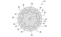
- FIG. 1 is a cross-sectional view schematically showing a double clad optical fiber according to the first embodiment of the present invention.
- FIG. 2 is a sectional view schematically showing a modification of the double clad optical fiber shown in FIG.
- FIG. 3 is a sectional view schematically showing another modified example of the double clad optical fiber shown in FIG.
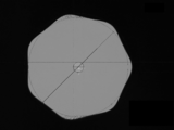
- FIG. 4 is a schematic diagram showing a cross-sectional shape perpendicular to the central axis of the inner cladding layer of the double clad optical fiber of FIG.
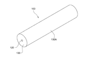
- FIG. 5 is a perspective view showing a glass material used for manufacturing the double clad optical fiber of FIG.
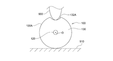
- FIG. 6 is a schematic view showing a step of forming a groove in the glass material of FIG. FIG.
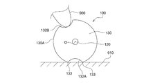
- FIG. 7 is a schematic diagram showing a state where the glass material is rotated after the process of FIG.
- FIG. 8 is a perspective view showing an optical fiber preform obtained by processing the glass material of FIG.
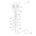
- FIG. 9 is a schematic diagram illustrating a drawing device used in the first embodiment of the present invention.
- FIG. 10 is a perspective view showing a glass material used for manufacturing a double clad optical fiber according to the second embodiment of the present invention.
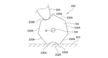
- FIG. 11 is a schematic view showing a step of forming a groove in the glass material of FIG.
- FIG. 12 is a schematic view showing a state where the glass material is rotated after the process of FIG.
- FIG. 13 is a perspective view schematically showing an optical fiber preform according to the second embodiment of the present invention.
- FIG. 14 is a schematic front view showing the optical fiber preform of FIG.
- FIG. 15 is a conceptual diagram for explaining the deepest groove that can be formed in the glass material shown in FIG.
- FIG. 16A is a micrograph showing a cross section of the double clad optical fiber according to the example of the present invention.
- FIG. 16B is a micrograph showing a cross section of the double clad optical fiber of Comparative Example 1.
- FIG. 16C is a micrograph showing a cross section of the double clad optical fiber of Comparative Example 2.
- FIGS. 1 to 16C a double clad optical fiber will be described as an example of a multi-clad optical fiber according to the present invention.
- the present invention can be applied to a multi-clad optical fiber having three or more clad layers.
- FIGS. 1 to 16C the same or corresponding components are denoted by the same reference numerals, and redundant description will be omitted. Also, in FIGS. 1 to 16C, the scale and size of each component may be exaggerated, or some components may be omitted.
- FIG. 1 is a cross-sectional view schematically showing a double clad optical fiber 10 according to the first embodiment of the present invention.
- the double clad optical fiber 10 according to the present embodiment includes a core 20 to which a rare earth element is added, an inner clad layer 30 (first clad layer) covering the outer periphery of the core 20, and an inner clad layer.
- An outer cladding layer (second cladding layer) that covers the outer periphery of the layer 30 and a coating layer that covers the outer periphery of the outer cladding layer are provided.
- the refractive index of the inner cladding layer 30 is lower than the refractive index of the core 20, so that the signal light propagates inside the core 20.
- the refractive index of the outer cladding layer 40 is lower than the refractive index of the inner cladding layer 30 so that the excitation light propagates inside the inner cladding layer 30.
- each recess 32 is formed by a curved surface, but may be formed by a plurality of planes (for example, in a V shape as shown in FIG. 2).
- each convex portion 34 is configured by a curved surface, but may be configured by a plurality of planes (for example, in an inverted V shape).
- the convex portion 34 protruding outward in the radial direction is formed between the adjacent concave portions 32, and the concave portion 32 concaved inward in the radial direction is formed between the adjacent convex portions 34.
- the space between the adjacent convex portions 34 may be formed by the flat surface 33 without forming the concave portion 32.
- the space between the adjacent concave portions 32 may be formed by a flat surface without forming the convex portions 34.
- the concave portions 32 are formed on the outer periphery of the inner clad layer 30, and the convex portions 34 are formed between these concave portions 32.
- the convex portions 34 are formed on the outer periphery of the inner cladding layer 30, and the concave portions 32 are formed between the convex portions 34. Therefore, the cross-sectional shape of the inner cladding layer 30 becomes non-circular. Therefore, it becomes difficult for the excitation light propagating in the inner cladding layer 30 to spiral spirally, and the propagation of the skew mode light in the inner cladding layer 30 is suppressed.
- the concave portion 32 and the convex portion 34 described above are maintained on the outer periphery of the inner clad layer even after the optical fiber base material is heated at a high temperature during manufacturing. Therefore, even when the amount of the rare earth element added to the core portion of the optical fiber preform is increased, it is possible to suppress the crystallization and phase separation of the rare earth oxide in the core 20 of the completed double clad optical fiber 10. As a result, light transmission loss is reduced.
- the convex portion 34 is formed by a curved surface, the portion formed by a plane in the inner cladding layer 30 is reduced, and cracks or chipping of the inner cladding layer 30 due to stress concentration that may occur on such a plane is eliminated. Can be suppressed.
- the protrusions 34 are formed between the adjacent recesses 32 so as to be continuous with the recesses 32.
- the convex portions 34 protruding outward in the radial direction are continuously formed in the adjacent concave portions 32, the convex portions 34 are smoothly connected to each other. And cracking or chipping of the inner cladding layer 30 due to stress concentration that can occur on such a plane can be suppressed.
- such a convex part 34 does not necessarily need to be formed continuously with the concave part 32.
- the concave portion 32 is formed between the adjacent convex portions 34 so as to be continuous with the convex portions 34.
- the convex portions 34 are smoothly connected to each other. It is possible to suppress cracking or chipping of the inner cladding layer 30 due to stress concentration that can occur on such a plane.
- such a concave portion 32 does not necessarily need to be formed continuously with the convex portion 34.
- FIG. 4 is a schematic diagram showing a cross-sectional shape of the inner cladding layer 30 perpendicular to the central axis O.
- a circle C1 inscribed in the outer shape of the cross section of the inner cladding layer 30 has a radius (radius R1) from the central axis O to a portion located inside the concave portion 32 of the inner cladding layer 30 in the most radial direction.
- the circle C2 circumscribing the outer shape of the cross section of the inner cladding layer 30 is a circle having a radius (radius R2) from the central axis O to a portion of the protrusion 34 of the inner cladding layer 30 located on the outermost side in the radial direction. .
- the ratio R1 / R2 of the radius R1 of the inscribed circle C1 to the radius R2 of the circumscribed circle C2 is large means that the cross-sectional shape of the inner cladding layer 30 approaches a circle, and as will be described later, In order to suppress the skew mode light propagating through 30, the smaller the radius ratio R1 / R2, the better.
- the radius ratio R1 / R2 is preferably 0.96 or less.
- a hollow quartz tube is prepared, and a necessary amount of a core component is deposited inside the quartz tube by, for example, an MCVD method to form a core portion.
- a cylindrical glass material 100 having the core part 120 and the clad part 130 located outside the core part 120 is obtained.
- the glass material 100 is fixed to a surface plate 910 of a machining center using hot wax or the like, and a diamond tool 900 having a curved end is set on the machining center.
- the groove 132A having a predetermined depth is formed along the longitudinal direction by moving in the axial direction while making contact with the cylindrical surface 130A.
- the glass material 100 is rotated around the central axis O so that the groove 132A faces the surface plate 910 of the machining center, and then the glass material 100 is again rotated. Is fixed to the surface plate 910. Then, the second groove 132B is formed by moving the diamond tool 900 in the axial direction while contacting the cylindrical surface 130A of the glass material 100.
- these steps of forming these grooves are performed seven times in total, and as shown in FIG. 8, the optical fiber preform 110 having seven grooves 132 recessed inward in the radial direction on the outer periphery is manufactured. These grooves 132 are formed at regular intervals in the circumferential direction, that is, at angular intervals of 2 ⁇ / 7.
- the preform 110 for an optical fiber is introduced into a drawing apparatus 800 as shown in FIG. 9 and drawn to manufacture the double clad optical fiber 10. That is, the optical fiber preform 110 is placed in a heating furnace 810 in a state where the optical fiber preform 110 is vertical, and the heating furnace 810 heats and melts the optical fiber preform 110. The optical fiber preform 110 that has been heated and melted is stretched in the vertical direction by its own weight to form a thread.
- the outer diameter of the fiber-shaped optical fiber material 111 is measured by the outer diameter monitor 820, it is introduced into the cooling pipe 830 and cooled.
- the cooled optical fiber material 112 is introduced into a first resin coating section 840, where a low refractive index resin is coated on the outer periphery.
- the optical fiber material 113 coated with the low-refractive-index resin is introduced into the first resin cured portion 850, where the low-refractive-index resin is cured by, for example, irradiation of ultraviolet rays, and the outer clad layer 40 (see FIG. 1). Is formed.
- the optical fiber material 114 on which the outer cladding layer 40 is formed is introduced into the second resin application section 860, where a coating resin is applied to the outer periphery.
- the optical fiber material 115 to which the coating resin has been applied is introduced into the second resin cured portion 870, where the coating resin is cured by, for example, irradiation of ultraviolet rays, and the coating layer 50 (see FIG. Ref) is formed.
- the optical fiber material 116 on which the coating layer 50 is formed is wound around the winding bobbin 890 at a predetermined speed by the capstan 880, and the double clad optical fiber 10 is completed.
- the optical fiber preform 110 Since a plurality of grooves 132 depressed inward in the radial direction are formed on the outer periphery of the optical fiber preform 110 manufactured by the above-described method, the optical fiber preform 110 is heated at a high temperature in the heating furnace 810. Even when heated, the concave portion 32 is formed in the inner clad layer 30 in the completed double clad optical fiber 10, and the cross-sectional shape of the inner clad layer 30 can be kept non-circular. In other words, the groove 132 of the optical fiber preform 110 changes into the concave portion 32 of the double clad optical fiber 10 by heating. Therefore, skew mode light in the inner cladding layer 30 can be effectively suppressed.
- the optical fiber preform 110 can be heated at a high temperature in this manner, even when the amount of the rare earth element added to the core portion 120 of the optical fiber preform 110 is increased, the completed double clad Crystallization and phase separation of the rare earth oxide in the core 20 of the optical fiber 10 can be suppressed, and light transmission loss can be reduced.
- a method for manufacturing a double-clad optical fiber according to the second embodiment of the present invention will be described.
- a necessary amount of a core component is deposited inside a hollow quartz tube by, for example, the MCVD method, and a glass material having a core portion 120 formed inside as shown in FIG.
- the cylindrical surface 130A of the glass material 100 is processed to obtain a regular heptagonal prism-shaped glass material 200 having seven side surfaces 230A as shown in FIG.
- Examples of the method of processing the cylindrical surface 130A of the glass material 100 include mechanical processing, laser processing, etching, and electrolytic polishing.
- the glass material 200 is fixed to the surface plate 910 using hot wax or the like while one side surface 230A of the glass material 200 is in contact with the surface plate 910 of the machining center.
- a groove 232A having a predetermined depth is formed along the longitudinal direction by moving in the axial direction while making contact with one side surface 230A of the glass material 200.
- the groove 232A may be formed in the side surface 230A while leaving a part of the side surface 230A of the glass material 200. In this case, the remaining side surface 230A is located on both sides of the formed groove 232A.
- the glass material 200 is rotated around the central axis O so that the groove 232A faces the surface plate 910 of the machining center, and then the glass material 200 is again formed. Is fixed to the surface plate 910.
- the second groove 232B is formed by moving the diamond tool 900 in the axial direction while making contact with another side surface 230A of the glass material 200.
- a groove 232B may be formed in the side surface 230A while leaving a part of the side surface 230A of the glass material 200.
- the step of forming these grooves is performed seven times in total, and as shown in FIGS. 13 and 14, the optical fiber base material 210 having seven grooves 232 recessed inward in the radial direction on the outer periphery is manufactured. .
- These grooves 232 are formed at regular intervals in the circumferential direction, that is, at angular intervals of 2 ⁇ / 7.
- optical fiber preform 210 is introduced into the drawing apparatus 800 shown in FIG. 9 and drawn in the same manner as in the first embodiment to manufacture a double clad optical fiber.
- the optical fiber preform 210 Since a plurality of grooves 232 recessed inward in the radial direction are formed on the outer periphery of the optical fiber preform 210 manufactured by the above-described method, the optical fiber preform 210 is heated at a high temperature in the heating furnace 810. Even when heated, a concave portion can be formed in the inner cladding layer of the completed double-clad optical fiber, and the cross-sectional shape of the inner cladding layer can be kept non-circular. In other words, the groove 232 of the optical fiber preform 210 changes into a concave portion of the double clad optical fiber by heating. Therefore, skew mode light in the inner cladding can be effectively suppressed.
- the optical fiber preform 210 can be heated at a high temperature in this manner, even when the amount of the rare earth element added to the core 220 of the optical fiber preform 210 is increased, the completed double clad Crystallization and phase separation of the rare earth oxide in the core of the optical fiber can be suppressed, and light transmission loss can be reduced.
- a plurality of protruding portions 234 protruding outward in the radial direction are formed on the outer periphery of the optical fiber preform 210 manufactured by the above-described method. Therefore, even if the optical fiber base material 210 is heated at a high temperature in the heating furnace 810, a convex portion is formed on the inner clad layer in the completed double-clad optical fiber, and the cross-sectional shape of the inner clad layer is kept non-circular. be able to. In other words, the protrusion 234 of the optical fiber preform 210 changes to a protrusion of the double clad optical fiber by heating. Therefore, skew mode light in the inner cladding layer can be effectively suppressed.
- the optical fiber preform can be heated at a high temperature in this manner, even when the amount of the rare earth element added to the core portion 120 of the optical fiber preform 210 is increased, the completed double clad light Crystallization and phase separation of the rare earth oxide in the fiber core can be suppressed, and light transmission loss can be reduced.
- the contact between the glass material 100 and the surface plate 910 makes contact with the edge 133 (FIG.
- the diamond tool 900 is pressed against the glass material 100 to perform grinding, stress concentrates on the edge 133 of the groove 132, and the glass material 100 is damaged or the completed double clad optical fiber is formed. It is considered that the strength of No. 10 is reduced.
- the cylindrical glass material 100 is formed into a regular heptagonal glass material 200 as shown in FIG. 10, while leaving a part of the side surface 230A of the regular heptagonal glass material 200, Since the groove 232 is formed on the side surface 230A, as shown in FIGS. 11 and 12, the contact between the glass material 200 and the surface plate 910 is caused by the entire side surface 230A or the side surface 230A remaining after the formation of the groove 232. Surface contact. Therefore, stress concentration when grinding is performed by pressing the diamond tool 900 against the glass material 100 is reduced, and damage to the glass material 200 and reduction in the strength of the double-clad optical fiber to be manufactured can be prevented.
- the side surface 230A remains after the groove 232 is formed on the side surface 230A of the glass material 200.
- the deepest groove 232 that can be formed in the glass material 200 is as shown in FIG.
- a circle C3 that forms the groove 232 in the cross section of the glass material 200 is formed when the vertices of the heptagon of the circle C3 pass through the central axis O.
- Equation (3) can be generalized to a preform for an optical fiber having an n prism, and the generalized equation is as shown in the following equation (4).
- R1 / R2 (1-sin ( ⁇ / n)) / cos ( ⁇ / n) (4)
- a double clad optical fiber was manufactured by the method according to the second embodiment described above.
- Yb was used as the rare earth element to be added to the core 20, and the addition amount was controlled so that the concentration of Yb was 3% by weight.
- the diamond tool 900 is pressed against each side surface 230A of the regular heptagonal prism-shaped glass material 200 to form the groove 232, the surface is deteriorated and roughened, so that it is cleaned by a chemical solution and processed by a flame.
- the surface was made transparent to produce an optical fiber preform 210.
- the groove 232 is formed by setting the ratio (side surface remaining ratio) of the side surface 230A of the glass material 100 to 2%, but the glass material 200 can be fixed on the surface plate 910 without any problem. did it. Also, no cracks or chips were found in the prepared optical fiber preform 210.
- the side surface residual ratio referred to here refers to the side surface of the glass material 200 after the formation of the groove 232 with respect to the region D1 (see FIG. 14) where the side surface 230A of the glass material 200 existed before the formation of the groove 232. It refers to the area ratio of the region (D1-D2) where 230A remains.
- D2 indicates a region where the side surface 230A of the glass material 200 does not exist after the groove 232 is formed.
- This optical fiber preform 210 was introduced into a drawing apparatus 800 and drawn to manufacture a double clad optical fiber. Specifically, the optical fiber preform 210 was placed in the heating furnace 810 in a vertical state, and the oxygen partial pressure in the heating furnace 810 was reduced by purging with an argon gas. Then, electric power of 20 kW was applied to the heating furnace 810 to heat and melt the distal end of the optical fiber preform 210. The melted optical fiber material was drawn at a predetermined tension and speed to obtain a double clad optical fiber.
- the first resin application section 840 an ultraviolet curable resin having a lower refractive index than that of the inner clad layer 30 is applied, and the first resin cured section 850 irradiates the ultraviolet curable resin with ultraviolet rays and cures the outer clad layer. Formed.
- the second resin application section 860 an ultraviolet curable resin was applied to the outside of the outer clad layer, and in the second resin cured section 870, the ultraviolet curable resin was irradiated with ultraviolet rays and cured to form a coating layer.
- the optical fiber material was rotated around the central axis to give a permanent twist to the optical fiber material.
- the rotation speed of the optical fiber material was controlled to be 4 rotations per 1 m of the length of the optical fiber material.
- Comparative Example 1 a double-clad optical fiber was manufactured using the heptagonal columnar glass material 200 shown in FIG. 10 as a base material for an optical fiber in the same manner as in the above-described example.
- the electric power supplied to the heating furnace 810 was set to 20 kW as in the above-described embodiment, and in Comparative Example 2, it was set to 18.5 kW.
- Example 2 For each of Example, Comparative Example 1, and Comparative Example 2, by measuring the optical transmission loss at a wavelength of 1180 nm using OTDR (Optical Time Domain Reflectometer) and measuring the absorption amount of the excitation light having a wavelength of 915 nm. The effect of suppressing skew mode light was evaluated. In the evaluation of the skew mode light suppressing effect, a skew suppressing index ⁇ calculated by the method described in Japanese Patent No. 6255532 was used. The larger the skew suppression index ⁇ , the more the occurrence of the skew mode is suppressed, and the maximum value is 1.
- FIGS. 16A, 16B, and 16C are photographs showing the cross sections of the double clad optical fibers of Example, Comparative Example 1, and Comparative Example 2, respectively. From these photographs, the radius R1 of the circle inscribed in the outer shape of the cross section perpendicular to the central axis of the inner cladding layer and the radius R2 of the circle circumscribed are obtained, and the ratio R1 / R1 of the radius R1 of the inscribed circle to the radius R2 of the circumscribed circle is obtained. R2 was calculated. In addition, R1 / R2 was similarly calculated for the optical fiber base material before drawing.
- the radius ratio R1 / R2 of the optical fiber preform was 0.901, but the completed optical fiber greatly increased to 0.972, and the skew suppression index ⁇ was increased. It has decreased to 0.92. This is presumably because the high-temperature heating by the heating furnace 810 rounded the corners of the heptagonal prism of the optical fiber preform, thereby reducing the radius R2 of the circumscribed circle and approaching R1 / R2 to one.
- the radius ratio R1 / R2 in the completed optical fiber was 0.959 in Comparative Example 2, which was processed at a lower temperature than that in Comparative Example 1, and did not increase as much as in Comparative Example 1.
- neither Comparative Example 1 nor Comparative Example 2 achieves both the reduction of the optical transmission loss and the effect of suppressing the skew.
- the embodiment realizes both the reduction of the optical transmission loss and the skew suppression effect. That is, in the embodiment, the optical transmission loss is reduced to 8 dB / km by increasing the temperature of the heating furnace 810, and the skew suppression index ⁇ is maintained at 1.00.
- the optical fiber base material 210 in the embodiment has the groove 232 recessed inward in the radial direction, so that the radius ratio R1 / R2 in the optical fiber base material 210 is reduced to 0.853. This is because even when the high-temperature heat treatment is performed, a concave portion is formed in the inner cladding layer in the completed optical fiber, so that the radius ratio R1 / R2 can be kept as small as 0.929.
- the radius ratio R1 / R2 in the manufactured optical fiber is preferably 0.96 or less.
- a base material for an optical fiber was manufactured with the side surface remaining rate of 0% when forming the groove 232 in the glass material 200, that is, without leaving the side surface 230A of the regular hexagonal prism.
- the ridge line of the prepared optical fiber preform was confirmed, cracks and chips having a size that could be visually confirmed were found in some places, but no cracks that propagated into the optical fiber preform were found.
- a double-clad optical fiber was manufactured from the optical fiber base material in the same manner as in the example.
- Example and Comparative Example 3 A 1% bending proof test was performed on a double-clad optical fiber having a length of 3 km. Although the double clad optical fiber of the example was broken twice, the morphology of the broken surface was a hackle pattern. As described above, in the example, a double-clad optical fiber having a sufficient length whose strength was guaranteed was obtained.
- the double clad optical fiber of Comparative Example 3 was frequently broken, and a mirror surface peculiar to the low-strength optical fiber was observed on the broken surface. In addition, it was confirmed that there was a fracture starting point at a portion corresponding to the ridge line of the heptagon.
- the side cladding ratio was set to 0% and the portion corresponding to the ridge of the heptagon was sharpened sharply, resulting in a low-strength, low-strength double-clad optical fiber. Conceivable.
- a double clad optical fiber was manufactured by drawing an optical fiber base material having a side surface residual ratio of 2% (the above example), 30%, 40%, and 100% (the above comparative example 1).
- the ratio R1 / R2 of the radius R1 of the inscribed circle to the radius R2 of the circumscribed circle and the skew suppression index ⁇ were calculated in the same manner as described above. Note that a power of 20 kW was supplied to the heating furnace 810.
- the grooves 132 and 232 are formed by mechanically processing the outer peripheral surfaces of the glass materials 100 and 200 using the diamond tool 900. A method of forming the grooves 132 and 232 is described. In addition to the mechanical processing, laser processing, etching, electrolytic polishing, and the like can be considered.
- the number of the concave portions 32 and the convex portions 34 formed in the inner cladding layer 30 and the number of the grooves 132 and 232 formed in the glass materials 100 and 200 are all seven. , These numbers may be 5, 6, 7, 8, or 9.
- a groove may be formed on each side surface of a pentagonal glass material, and five concave portions may be formed in an inner cladding layer of an optical fiber to be manufactured.
- the concave portions 32 and the convex portions described above may be provided on any clad layer disposed inside the clad layer having a relatively low refractive index.
- the part 34 can be formed.
- a multi-clad optical fiber having an effect of suppressing skew mode light in a cladding layer and having a small light transmission loss in a core.
- the multi-cladding optical fiber includes a core, a first cladding layer located outside the core, and a second cladding layer covering the outer periphery of the first cladding layer.
- the second cladding layer has a lower refractive index than that of the first cladding layer.
- On the outer periphery of the first cladding layer a plurality of concave portions that are recessed inward in the radial direction are formed so as to be separated from each other in the circumferential direction.
- the number of the plurality of recesses may be 5, 6, 7, 8, or 9.
- the recess may have a curved surface.
- the concave portion that is concave inward in the radial direction is formed on the outer periphery of the first cladding layer, the cross-sectional shape of the first cladding layer becomes non-circular. Therefore, the light propagating through the first cladding layer is less likely to spiral, and the propagation of the skew mode light through the first cladding layer is suppressed.
- the optical fiber preform is manufactured by heating at a high temperature, the above-described recess is maintained on the outer periphery of the first clad layer of the multi-clad optical fiber, and the skew mode light is suppressed.
- the amount of the rare earth element added to the core portion of the fiber preform is increased, the crystallization and phase separation of the rare earth oxide in the core of the multi-clad optical fiber can be suppressed by high-temperature heating. Therefore, light transmission loss in the multi-clad optical fiber is reduced.
- a convex portion having a curved surface and protruding outward in the radial direction is formed between the adjacent concave portions.
- the cross-sectional shape of the first cladding layer becomes more non-circular, so that propagation of skew mode light through the first cladding layer is more effectively suppressed.
- the convex portion has a curved surface, a portion formed by a plane in the first cladding layer is reduced, so that cracking or chipping of the first cladding layer due to stress concentration that can occur in such a plane can be suppressed.
- a convex portion protruding radially outward may be formed continuously with the adjacent concave portions.
- the convex portions projecting outward in the radial direction are continuously formed in the adjacent concave portions, the convex portions are smoothly connected to each other. Further, cracks and chipping of the first cladding layer due to stress concentration that can occur on such a plane can be suppressed.
- a multi-clad optical fiber having an effect of suppressing skew mode light in a cladding layer and having a small light transmission loss in a core.
- the multi-cladding optical fiber includes a core, a first cladding layer located outside the core, and a second cladding layer covering the outer periphery of the first cladding layer.
- the second cladding layer has a lower refractive index than that of the first cladding layer.
- On the outer periphery of the first cladding layer a plurality of convex portions projecting outward in the radial direction are formed so as to be spaced apart from each other in the circumferential direction.
- the number of the plurality of protrusions may be 5, 6, 7, 8, or 9.
- the convex portion projecting outward in the radial direction is formed on the outer periphery of the first clad layer, the cross-sectional shape of the first clad layer is non-circular. Therefore, the light propagating through the first cladding layer is less likely to spiral, and the propagation of the skew mode light through the first cladding layer is suppressed.
- the optical fiber preform is manufactured by heating at a high temperature, the above-described convex portion is maintained on the outer periphery of the first cladding layer of the multi-clad optical fiber, and the skew mode light is suppressed.
- the amount of the rare earth element added to the core of the optical fiber preform is increased, the crystallization and phase separation of the rare earth oxide in the core of the multi-clad optical fiber can be suppressed by high-temperature heating. Therefore, light transmission loss in the multi-clad optical fiber is reduced.
- a concave portion having a curved surface and concave inward in the radial direction is formed between the adjacent concave portions.
- Such a concave portion makes the cross-sectional shape of the first cladding layer more non-circular, so that the propagation of skew mode light through the first cladding layer is more effectively suppressed.
- a concave portion may be formed between the adjacent convex portions, the concave portion being recessed radially inward from the adjacent convex portion.
- the concave portion is smoothly connected to each other, so that the portion constituted by the flat surface in the first cladding layer is reduced. Further, cracks and chipping of the first cladding layer due to stress concentration that can occur on such a plane can be suppressed.
- the convex portion may have a curved surface.
- a portion formed by a plane in the first cladding layer is reduced, and cracking or chipping of the first cladding layer due to stress concentration that can occur in such a plane is suppressed. it can.
- a cross section perpendicular to the central axis of the first cladding layer is required.
- the ratio of the radius of the circle inscribed in the outer shape to the radius of the circle circumscribed in the outer shape is 0.96 or less.
- an optical fiber preform that has an effect of suppressing skew mode light in a cladding layer and can realize an optical fiber with small light transmission loss in a core.
- This optical fiber preform includes a core portion and a clad portion located outside the core portion. A plurality of grooves depressed inward in the radial direction are formed on the outer periphery of the clad portion so as to be spaced apart from each other in the circumferential direction.
- the optical fiber preform is heated at a high temperature during drawing.
- the completed optical fiber can hold a concave portion that is recessed radially inward in the clad layer, and the cross-sectional shape of the clad layer can be made non-circular. Therefore, it is difficult for the light propagating through the clad layer to spiral spirally, and the propagation of the skew mode light through the clad layer is suppressed.
- the optical fiber preform can be heated at a high temperature in this manner, even when the amount of the rare earth element added to the core portion of the optical fiber preform is increased, the finished optical fiber core can be heated. Crystallization and phase separation of the rare earth oxide can be suppressed, and light transmission loss can be reduced.
- the plurality of grooves may be composed of n grooves, and n may be 5, 6, 7, 8, or 9.
- the ratio of the radius of the circle circumscribed to the outer shape to the radius of the circle circumscribed to the outer shape of the cross section perpendicular to the center axis of the clad portion is (1-sin ( ⁇ / n)) / cos ( ⁇ / n) or more.
- an optical fiber preform having an effect of suppressing skew mode light in a cladding layer and capable of realizing an optical fiber having a small light transmission loss in a core.
- This optical fiber preform includes a core portion and a clad portion located outside the core portion. On the outer periphery of the clad portion, a plurality of projecting portions projecting outward in the radial direction are formed apart from each other in the circumferential direction.
- the optical fiber preform is heated at a high temperature during drawing.
- the completed optical fiber can hold the protrusion protruding radially outward on the cladding layer, and the cross-sectional shape of the cladding layer can be made non-circular. Therefore, it is difficult for the light propagating through the clad layer to spiral spirally, and the propagation of the skew mode light through the clad layer is suppressed.
- the optical fiber preform can be heated at a high temperature in this manner, even when the amount of the rare earth element added to the core portion of the optical fiber preform is increased, the finished optical fiber core can be heated. Crystallization and phase separation of the rare earth oxide can be suppressed, and light transmission loss can be reduced.
- the protruding portion is formed by a surface constituting a part of a side surface of the polygonal prism.
- the contact between the surface plate used for forming the protruding portion and the optical fiber preform can be a surface contact, and the stress concentration at the time of forming the protruding portion can be made. Can be alleviated. Therefore, it is possible to prevent the preform for the optical fiber from being damaged and the strength of the manufactured multi-clad optical fiber from being reduced.
- a preform for an optical fiber which has an effect of suppressing skew mode light in a cladding layer and can realize a multi-clad optical fiber with small light transmission loss in a core is manufactured.
- a method is provided. In this method, a glass material having a core portion and a clad portion located outside the core portion is prepared, and a plurality of grooves depressed inward in the radial direction are circumferentially separated from each other in the outer periphery of the glass material. Forming an optical fiber preform.
- the optical fiber preform can be heated at a high temperature in this manner, even when the amount of the rare earth element added to the core of the optical fiber preform is increased, the multi-clad optical fiber produced The crystallization and phase separation of the rare earth oxide in the core can be suppressed, and a multi-clad optical fiber with small light transmission loss can be obtained.
- the outer periphery of the glass material may be processed to have a polygonal column shape.
- the groove when forming the groove on the outer periphery of the glass material, the groove may be formed on the side surface while leaving a part of each side surface of the polygonal prism. In this way, when forming a groove on the outer periphery of the glass material, the contact between the surface plate used for forming the groove and the glass material becomes a surface contact, so that stress concentration when forming the groove is performed. Is reduced, and damage to the optical fiber base material and reduction in the strength of the double-clad optical fiber to be produced can be prevented.
- the groove When forming the groove on the outer periphery of the glass material, the groove may be formed on a cylindrical surface of the glass material.
- a preform for an optical fiber which has an effect of suppressing skew mode light in a cladding layer and can realize a multi-clad optical fiber with small light transmission loss in a core is manufactured.
- a method is provided. In this method, a glass material having a core portion and a clad portion located outside the core portion is prepared, and the outer periphery of the glass material is processed into a polygonal column shape, and each side surface of the polygonal column of the glass material is formed. While leaving a part of the groove.
- the optical fiber preform can be heated at a high temperature in this manner, even when the amount of the rare earth element added to the core of the optical fiber preform is increased, the multi-clad optical fiber produced The crystallization and phase separation of the rare earth oxide in the core can be suppressed, and a multi-clad optical fiber with small light transmission loss can be obtained.
- the seventh aspect of the present invention there is provided a method of manufacturing a multi-clad optical fiber having an effect of suppressing skew mode light in a clad layer and capable of obtaining a multi-clad optical fiber having a small light transmission loss in a core.
- the optical fiber preform is manufactured by the method described above, and the manufactured optical fiber preform is heated and stretched, and the periphery of the clad portion of the stretched optical fiber preform is heated.
- a multi-clad optical fiber is manufactured by applying and curing a resin having a lower refractive index than the clad portion.
- skew mode light in the cladding layer can be effectively suppressed, and light transmission loss in the core can be reduced.
- the present invention is suitably used for a multi-clad optical fiber having a plurality of clad layers.
- Double-clad optical fiber (multi-clad optical fiber) Reference Signs List 20 core 30 inner cladding layer 32 concave part 34 convex part 40 outer cladding layer 50 coating layer 100 glass material 110 optical fiber base material 120 core part 130 clad part 130A cylindrical surface 132 groove 200 glass material 210 optical fiber base material 220 core part 230A side surface 232 groove 800 wire drawing device 810 heating furnace 820 outer diameter monitor 830 cooling pipe 840 first resin coating section 850 first resin curing section 860 second resin coating section 870 second resin curing section 880 capstan 890 winding Taking bobbin 900 Diamond tool 910 Surface plate O Central axis
Landscapes
- Physics & Mathematics (AREA)
- Optics & Photonics (AREA)
- Engineering & Computer Science (AREA)
- General Physics & Mathematics (AREA)
- Electromagnetism (AREA)
- Chemical & Material Sciences (AREA)
- Life Sciences & Earth Sciences (AREA)
- General Life Sciences & Earth Sciences (AREA)
- Geochemistry & Mineralogy (AREA)
- Manufacturing & Machinery (AREA)
- Plasma & Fusion (AREA)
- Materials Engineering (AREA)
- Organic Chemistry (AREA)
- Lasers (AREA)
Abstract
本発明は、クラッド層におけるスキューモード光の抑制効果を有し、コアにおける光の伝送損失の少ないマルチクラッド光ファイバを提供する。ダブルクラッド光ファイバ10は、コア20と、コア20の外側に位置する内側クラッド層30と、内側クラッド層30の外周を被覆する外側クラッド層40とを備えている。外側クラッド層40は、内側クラッド層30の屈折率よりも低い屈折率を有している。内側クラッド層30の外周には、半径方向内側に凹んだ凹部32が周方向に互いに離間されて複数個形成されている。
Description
本発明は、マルチクラッド光ファイバ、光ファイバ用母材、光ファイバ用母材の製造方法、及びマルチクラッド光ファイバの製造方法に係り、特に複数のクラッド層を有するマルチクラッド光ファイバの製造方法に関するものである。
複数のクラッド層を有するマルチクラッド光ファイバとしては、例えば、光増幅器やファイバレーザなどで用いられるダブルクラッド光ファイバが知られている。このダブルクラッド光ファイバにおいては、外側クラッドに覆われた内側クラッドを導波路として伝搬する励起光がコアを横切る際にコア中の希土類イオンを励起して信号光を増幅する。しかしながら、内側クラッドの断面形状が円形である場合には、励起光の入射角度によって一部の励起光が、コアを通らずに内側クラッド内を螺旋状に旋回(スキュー)し、励起に寄与しないスキューモード光となってしまう。このようなスキューモード光が増えると励起効率が悪くなるため、内側クラッドの断面形状を非円形にしてスキューモード光を散乱させることもなされている(例えば、特許文献1参照)。
一方、近年のレーザ光の高出力化に伴い、このようなダブルクラッド光ファイバにおける増幅量を増やすために、コアに添加する希土類元素の量を増やす傾向にある。このように希土類元素の添加量が増えると、光ファイバを製造する際に、光ファイバ用母材を線引きするときの熱処理において、希土類酸化物を主体とする成分がコア内に結晶化したり、相分離したりする現象が生じやすくなる。これらの現象が起こると、コアの組織が不均質になるため、光の伝搬損失が大きくなってしまう。このような希土類酸化物の結晶化や相分離を抑制するためには、線引きの際に均質になるまでコアを十分に加熱することが必要とされる。
しかしながら、内側クラッドの断面形状が非円形のダブルクラッド光ファイバを製造する際に、断面形状が非円形の光ファイバ用母材を高温で線引きすると、熱によって非円形の断面形状の角部が丸くなって、内側クラッドの断面形状が円形に近づいてしまい、スキューモード光を抑制する効果が低減してしまう。
本発明は、このような従来技術の問題点に鑑みてなされたもので、クラッド層におけるスキューモード光の抑制効果を有し、コアにおける光の伝送損失の少ないマルチクラッド光ファイバを提供することを第1の目的とする。
また、本発明は、クラッド層におけるスキューモード光の抑制効果を有し、コアにおける光の伝送損失の少ない光ファイバを実現することができる光ファイバ用母材を提供することを第2の目的とする。
さらに、本発明は、クラッド層におけるスキューモード光の抑制効果を有し、コアにおける光の伝送損失の少ない光ファイバを実現することができる光ファイバ用母材を製造することができる方法を提供することを第3の目的とする。
また、本発明は、クラッド層におけるスキューモード光の抑制効果を有し、コアにおける光の伝送損失の少ないマルチクラッド光ファイバを得ることができるマルチクラッド光ファイバの製造方法を提供することを第4の目的とする。
本発明の第1の態様によれば、クラッド層におけるスキューモード光の抑制効果を有し、コアにおける光の伝送損失の少ないマルチクラッド光ファイバが提供される。このマルチクラッド光ファイバは、コアと、上記コアの外側に位置する第1のクラッド層と、上記第1のクラッド層の外周を被覆する第2のクラッド層とを備えている。上記第2のクラッド層は、上記第1のクラッド層の屈折率よりも低い屈折率を有している。上記第1のクラッド層の上記外周には、半径方向内側に凹んだ凹部が周方向に互いに離間されて複数個形成されている。
本発明の第2の態様によれば、クラッド層におけるスキューモード光の抑制効果を有し、コアにおける光の伝送損失の少ないマルチクラッド光ファイバが提供される。このマルチクラッド光ファイバは、コアと、上記コアの外側に位置する第1のクラッド層と、上記第1のクラッド層の外周を被覆する第2のクラッド層とを備えている。上記第2のクラッド層は、上記第1のクラッド層の屈折率よりも低い屈折率を有する。上記第1のクラッド層の上記外周には、半径方向外側に突出する凸部が周方向に互いに離間されて複数個形成されている。
本発明の第3の態様によれば、クラッド層におけるスキューモード光の抑制効果を有し、コアにおける光の伝送損失の少ない光ファイバを実現することができる光ファイバ用母材が提供される。この光ファイバ用母材は、コア部と、上記コア部の外側に位置するクラッド部とを備える。上記クラッド部の外周には、半径方向内側に凹んだ溝が周方向に互いに離間されて複数本形成されている。
本発明の第4の態様によれば、クラッド層におけるスキューモード光の抑制効果を有し、コアにおける光の伝送損失の少ない光ファイバを実現することができる光ファイバ用母材が提供される。この光ファイバ用母材は、コア部と、上記コア部の外側に位置するクラッド部とを備えている。上記クラッド部の外周には、半径方向外側に突出する突出部が周方向に互いに離間されて複数個形成されている。
本発明の第5の態様によれば、クラッド層におけるスキューモード光の抑制効果を有し、コアにおける光の伝送損失の少ないマルチクラッド光ファイバを実現することができる光ファイバ用母材を製造する方法が提供される。この方法では、コア部と該コア部の外側に位置するクラッド部とを有するガラス材を用意し、上記ガラス材の外周に、半径方向内側に凹んだ溝を周方向に互いに離間して複数本形成して光ファイバ用母材を形成する。
本発明の第6の態様によれば、クラッド層におけるスキューモード光の抑制効果を有し、コアにおける光の伝送損失の少ないマルチクラッド光ファイバを実現することができる光ファイバ用母材を製造する方法が提供される。この方法では、コア部と該コア部の外側に位置するクラッド部とを有するガラス材を用意し、上記ガラス材の外周を加工して多角柱状にし、上記ガラス材の上記多角柱のそれぞれの側面の一部を残しつつ、該側面に溝を形成する。
本発明の第7の態様によれば、クラッド層におけるスキューモード光の抑制効果を有し、コアにおける光の伝送損失の少ないマルチクラッド光ファイバを得ることができるマルチクラッド光ファイバの製造方法が提供される。この方法によれば、上述した方法により光ファイバ用母材を製造し、この製造された光ファイバ用母材を加熱して延伸し、上記延伸された光ファイバ用母材の上記クラッド部の周囲に該クラッド部よりも屈折率の低い樹脂を塗布して硬化させることにより、マルチクラッド光ファイバが製造される。
以下、本発明に係るマルチクラッド光ファイバ及びその製造方法の実施形態について図1から図16Cを参照して詳細に説明する。なお、以下の説明では、本発明に係るマルチクラッド光ファイバとしてダブルクラッド光ファイバを例として説明するが、本発明は3つ以上のクラッド層を有するマルチクラッド光ファイバにも適用できることは言うまでもない。図1から図16Cにおいて、同一又は相当する構成要素には、同一の符号を付して重複した説明を省略する。また、図1から図16Cにおいては、各構成要素の縮尺や寸法が誇張されて示されている場合や一部の構成要素が省略されている場合がある。
図1は、本発明の第1の実施形態におけるダブルクラッド光ファイバ10を模式的に示す断面図である。図1に示すように、本実施形態におけるダブルクラッド光ファイバ10は、希土類元素が添加されたコア20と、コア20の外周を被覆する内側クラッド層30(第1のクラッド層)と、内側クラッド層30の外周を被覆する外側クラッド層40(第2のクラッド層)と、外側クラッド層40の外周を被覆する被覆層50とを有している。内側クラッド層30の屈折率はコア20の屈折率よりも低くなっており、コア20の内部を信号光が伝搬するようになっている。外側クラッド層40の屈折率は内側クラッド層30の屈折率よりも低くなっており、内側クラッド層30の内部を励起光が伝搬するようになっている。
図1に示すように、内側クラッド層30の外周には、半径方向内側に凹んだ7つの凹部32が形成されている。これらの凹部32は、周方向に互いに離間されて形成されている。本実施形態では、これらの凹部32が周方向に等間隔で、すなわち2π/7の角度間隔で形成されているが、必ずしも周方向に一定の角度間隔で形成されている必要はない。本実施形態では、それぞれの凹部32は曲面により構成されているが、複数の平面により(例えば、図2に示すようにV字状に)構成されていてもよい。
また、内側クラッド層30の外周には、半径方向外側に突出する7つの凸部34が形成されている。これらの凸部34は、周方向に互いに離間されて形成されている。本実施形態では、これらの凸部34が周方向に等間隔で、すなわち2π/7の角度間隔で形成されているが、必ずしも周方向に一定の角度間隔で形成されている必要はない。本実施形態では、それぞれの凸部34は曲面により構成されているが、複数の平面により(例えば逆V字状に)構成されていてもよい。
このように、隣り合う凹部32の間には、半径方向外側に突出する凸部34が形成されており、隣り合う凸部34の間には、半径方向内側に凹んだ凹部32が形成されている。なお、図3に示すように、凹部32が形成されずに、隣り合う凸部34の間が平面33により構成されていてもよい。また、凸部34が形成されずに、隣り合う凹部32の間が平面により構成されていてもよい。
本実施形態のダブルクラッド光ファイバ10においては、内側クラッド層30の外周に凹部32が形成されており、また、これらの凹部32の間には凸部34が形成されている。換言すれば、内側クラッド層30の外周に凸部34が形成されており、また、これらの凸部34の間には凹部32が形成されている。このため、内側クラッド層30の断面形状が非円形となる。したがって、内側クラッド層30を伝搬する励起光が螺旋状に旋回しにくくなり、内側クラッド層30をスキューモード光が伝搬することが抑制される。
また、このようなダブルクラッド光ファイバ10は、製造する際に光ファイバ用母材を高温で加熱した後においても、内側クラッド層の外周に上述した凹部32及び凸部34が維持される。したがって、光ファイバ用母材のコア部に添加する希土類元素の量を増加させた場合においても、完成したダブルクラッド光ファイバ10のコア20における希土類酸化物の結晶化や相分離を抑制することができるので、光の伝送損失が低減される。さらに、本実施形態では、凸部34が曲面により構成されているので、内側クラッド層30において平面により構成される部分が減り、かかる平面において生じ得る応力集中による内側クラッド層30の割れや欠けを抑制することができる。
本実施形態では、隣り合う凹部32の間に、凸部34が凹部32に連続して形成されている。このように、半径方向外側に突出する凸部34を隣り合う凹部32に連続して形成することで、凸部34同士が滑らかに接続されるため、内側クラッド層30において平面により構成される部分が減り、かかる平面において生じ得る応力集中による内側クラッド層30の割れや欠けを抑制することができる。なお、このような凸部34は必ずしも凹部32に連続して形成されていなくてもよい。
また、本実施形態では、隣り合う凸部34の間に、凹部32が凸部34に連続して形成されている。このように、半径方向内側に凹む凹部32を隣り合う凸部34に連続して形成することで、凸部34同士が滑らかに接続されるため、内側クラッド層30において平面により構成される部分が減り、かかる平面において生じ得る応力集中による内側クラッド層30の割れや欠けを抑制することができる。なお、このような凹部32は必ずしも凸部34に連続して形成されていなくてもよい。
図4は、内側クラッド層30の中心軸Oに垂直な断面の形状を示す模式図である。図4に示すように、内側クラッド層30の断面の外形に内接する円C1は、中心軸Oから内側クラッド層30の凹部32の最も半径方向内側に位置する部分までを半径(半径R1)とする円となる。また、内側クラッド層30の断面の外形に外接する円C2は、中心軸Oから内側クラッド層30の凸部34の最も半径方向外側に位置する部分までを半径(半径R2)とする円となる。この外接円C2の半径R2に対する内接円C1の半径R1の比R1/R2が大きいことは、内側クラッド層30の断面形状が円形に近づくことを意味しており、後述するように内側クラッド層30を伝搬するスキューモード光を抑制するためには、この半径比R1/R2が小さい方がよい。特に、この半径比R1/R2は0.96以下であることが好ましい。
次に、このような構成のダブルクラッド光ファイバ10を製造する方法の一例について説明する。まず、中空の石英管を用意し、この石英管の内側に例えばMCVD法によりコア成分を必要な量だけ堆積させてコア部を形成する。これにより、図5に示すように、コア部120とコア部120の外側に位置するクラッド部130とを有する円筒状のガラス材100が得られる。
次に、図6に示すように、ガラス材100をマシニングセンタの定盤910にホットワックスなどを用いて固定し、先端が曲面のダイヤモンドツール900をマシニングセンタにセットし、このダイヤモンドツール900をガラス材100の円筒面130Aに接触させつつ、軸方向に移動させることで所定の深さの溝132Aを長手方向に沿って形成する。
1本目の溝132Aを形成した後、図7に示すように、この溝132Aがマシニングセンタの定盤910に対向するようにガラス材100を中心軸O周りに回転させた上で、再度ガラス材100を定盤910に固定する。そして、ダイヤモンドツール900をガラス材100の円筒面130Aに接触させつつ、軸方向に移動させることで2本目の溝132Bを形成する。
これらの溝を形成する工程を合計で7回行い、図8に示すように、外周に半径方向内側に凹んだ7本の溝132が形成された光ファイバ用母材110を作製する。これらの溝132は、周方向に等間隔で、すなわち2π/7の角度間隔で形成されている。
次に、この光ファイバ用母材110を図9に示すような線引き装置800に導入して線引きし、ダブルクラッド光ファイバ10を製造する。すなわち、光ファイバ用母材110を垂直にした状態で加熱炉810内に配置し、加熱炉810により光ファイバ用母材110を加熱溶融する。加熱溶融された光ファイバ用母材110は、自重により鉛直方向に延伸されて糸状になる。
糸状になった光ファイバ材料111は、その外径が外径モニタ820で測定された後、冷却管830に導入されて冷却される。冷却された光ファイバ材料112は、第1の樹脂塗布部840に導入され、ここで外周に低屈折率樹脂が塗布される。低屈折率樹脂が塗布された光ファイバ材料113は、第1の樹脂硬化部850に導入され、ここで例えば紫外線の照射などにより低屈折率樹脂が硬化し、外側クラッド層40(図1参照)が形成される。
外側クラッド層40が形成された光ファイバ材料114は、第2の樹脂塗布部860に導入され、ここで外周に被覆樹脂が塗布される。被覆樹脂が塗布された光ファイバ材料115は、第2の樹脂硬化部870に導入され、ここで例えば紫外線の照射などにより被覆樹脂が硬化し、外側クラッド層40の外周に被覆層50(図1参照)が形成される。
被覆層50が形成された光ファイバ材料116は、キャプスタン880により所定の速度で巻取ボビン890に巻き取られ、ダブルクラッド光ファイバ10が完成する。
上述した方法により作製された光ファイバ用母材110の外周には、半径方向内側に凹んだ複数本の溝132が形成されているため、この光ファイバ用母材110を加熱炉810において高温で加熱しても、完成したダブルクラッド光ファイバ10において内側クラッド層30に凹部32が形成され、内側クラッド層30の断面形状を非円形に維持することができる。換言すれば、光ファイバ用母材110の溝132が加熱によりダブルクラッド光ファイバ10の凹部32に変化する。したがって、内側クラッド層30におけるスキューモード光を効果的に抑制することができる。また、このように光ファイバ用母材110を高温で加熱することができるため、光ファイバ用母材110のコア部120に添加する希土類元素の量を増加させた場合においても、完成したダブルクラッド光ファイバ10のコア20における希土類酸化物の結晶化や相分離を抑制することができ、光の伝送損失を低減することができる。
次に、本発明の第2の実施形態におけるダブルクラッド光ファイバの製造方法について説明する。まず、第1の実施形態と同様に、中空の石英管の内側に例えばMCVD法によりコア成分を必要な量だけ堆積させて、図5に示すような内部にコア部120が形成されたガラス材100を得た後、ガラス材100の円筒面130Aを加工して、図10に示すように、7つの側面230Aを有する正七角柱状のガラス材200を得る。ガラス材100の円筒面130Aを加工する方法の例としては、機械的加工、レーザ加工、エッチング、電解研磨などが挙げられる。
図11に示すように、このガラス材200の1つの側面230Aをマシニングセンタの定盤910に当接させた状態でガラス材200をホットワックスなどを用いて定盤910に固定し、ダイヤモンドツール900をガラス材200の1つの側面230Aに接触させつつ、軸方向に移動させることで所定の深さの溝232Aを長手方向に沿って形成する。このとき、ガラス材200の側面230Aの一部を残しつつ、側面230Aに溝232Aを形成してもよい。この場合には、形成された溝232Aの両側に、残存した側面230Aが位置する。
1本目の溝232Aを形成した後、図12に示すように、この溝232Aがマシニングセンタの定盤910に対向するようにガラス材200を中心軸O周りに回転させた上で、再度ガラス材200を定盤910に固定する。そして、ダイヤモンドツール900をガラス材200の別の側面230Aに接触させつつ、軸方向に移動させることで2本目の溝232Bを形成する。このときも上記と同様に、ガラス材200の側面230Aの一部を残しつつ、側面230Aに溝232Bを形成してもよい。
これらの溝を形成する工程を合計で7回行い、図13及び図14に示すように、外周に半径方向内側に凹んだ7本の溝232が形成された光ファイバ用母材210を作製する。これらの溝232は、周方向に等間隔で、すなわち2π/7の角度間隔で形成されている。
図14に示すように、光ファイバ用母材210のクラッド部130に形成されたそれぞれの溝232の両側には、正七角柱のガラス材200の側面230Aの一部が残っており、隣り合う側面230Aによって半径方向外側に突出する突出部234が形成されている。
次に、この光ファイバ用母材210を第1の実施形態と同様に図9に示す線引き装置800に導入して線引きし、ダブルクラッド光ファイバを製造する。
上述した方法により作製された光ファイバ用母材210の外周には、半径方向内側に凹んだ複数本の溝232が形成されているため、この光ファイバ用母材210を加熱炉810において高温で加熱しても、完成したダブルクラッド光ファイバの内側クラッド層に凹部を形成することができ、内側クラッド層の断面形状を非円形に維持することができる。換言すれば、光ファイバ用母材210の溝232が加熱によりダブルクラッド光ファイバの凹部に変化する。したがって、内側クラッドにおけるスキューモード光を効果的に抑制することができる。また、このように光ファイバ用母材210を高温で加熱することができるため、光ファイバ用母材210のコア部220に添加する希土類元素の量を増加させた場合においても、完成したダブルクラッド光ファイバのコアにおける希土類酸化物の結晶化や相分離を抑制することができ、光の伝送損失を低減することができる。
また、上述した方法により作製された光ファイバ用母材210の外周には、半径方向外側に突出する複数の突出部234が形成されている。したがって、この光ファイバ用母材210を加熱炉810において高温で加熱しても、完成したダブルクラッド光ファイバにおいて内側クラッド層に凸部が形成され、内側クラッド層の断面形状を非円形に維持することができる。換言すれば、光ファイバ用母材210の突出部234が加熱によりダブルクラッド光ファイバの凸部に変化する。したがって、内側クラッド層におけるスキューモード光を効果的に抑制することができる。また、このように光ファイバ用母材を高温で加熱することができるため、光ファイバ用母材210のコア部120に添加する希土類元素の量を増加させた場合においても、完成したダブルクラッド光ファイバのコアにおける希土類酸化物の結晶化や相分離を抑制することができ、光の伝送損失を低減することができる。
ここで、上述した第1の実施形態では、溝132を形成する際に、図7に示すように、ガラス材100と定盤910との間の接触は、溝132の縁部133(図7)における線接触であるため、ダイヤモンドツール900をガラス材100に押し当てて研削を行うと、溝132の縁部133に応力が集中し、ガラス材100が破損したり、完成したダブルクラッド光ファイバ10の強度が低下したりすることが考えられる。
これに対して、本実施形態では、円筒状のガラス材100を図10に示すような正七角柱のガラス材200とした後に、この正七角柱のガラス材200の側面230Aの一部を残しつつ、この側面230Aに溝232を形成しているため、図11及び図12に示すように、ガラス材200と定盤910との間の接触は、側面230A全体又は溝232の形成後に残存した側面230Aにおける面接触となる。したがって、ダイヤモンドツール900をガラス材100に押し当てて研削を行った際の応力集中が緩和され、ガラス材200の破損や作製されるダブルクラッド光ファイバの強度の低下を防ぐことができる。
このように、ガラス材200の側面230Aに溝232を形成した後に側面230Aが残っていることがより好ましいが、理論上、ガラス材200に形成し得る最も深い溝232は、図15に示すように、ガラス材200の断面において溝232を形成する円C3が七角形の頂点を通過し、かつ円C3の七角形の頂点における接線が中心軸Oを通過するときに形成される。このとき、クラッド部130の断面の外形に内接する円C1の半径をR1、クラッド部130の断面の外形に外接する円C2の半径をR2、円C3の半径をrとすると、以下の式(1)及び(2)が成立する。
(R1+r)sinα=r ・・・(1)
(R1+r)cosα=R2 ・・・(2)
ここでα=π/7である。
(R1+r)sinα=r ・・・(1)
(R1+r)cosα=R2 ・・・(2)
ここでα=π/7である。
これらの式から以下の式(3)を得ることができる。
R1/R2=(1-sinα)/cosα ・・・(3)
ここで、α=π/7であるから、R1/R2=0.63となる。したがって、光ファイバ用母材210におけるR1/R2の最小値は0.63である。
R1/R2=(1-sinα)/cosα ・・・(3)
ここで、α=π/7であるから、R1/R2=0.63となる。したがって、光ファイバ用母材210におけるR1/R2の最小値は0.63である。
上記式(3)はn角柱の光ファイバ用母材に一般化することができ、その一般化式は以下の式(4)のようになる。
R1/R2=(1-sin(π/n))/cos(π/n) ・・・(4)
R1/R2=(1-sin(π/n))/cos(π/n) ・・・(4)
上述した第2の実施形態に係る方法によりダブルクラッド光ファイバを製造した。コア20に添加する希土類元素としてはYbを用い、Ybの濃度が3重量%となるように添加量を制御した。正七角柱状のガラス材200の各側面230Aにダイヤモンドツール900を押し当てて溝232を形成した後は表面が変質し、粗面化されているため、薬液による洗浄及び火炎を用いた加工処理により表面を透明化して、光ファイバ用母材210を作製した。
ここで、溝232を形成する際にガラス材100の側面230Aを残す割合(側面残存率)を2%として溝232を形成したが、ガラス材200を問題なく定盤910上に固定することができた。また、作製した光ファイバ用母材210にも割れや欠けが認められなかった。なお、ここでいう側面残存率とは、溝232を形成する前においてガラス材200の側面230Aが存在していた領域D1(図14参照)に対する、溝232を形成した後においてガラス材200の側面230Aが残存している領域(D1-D2)の面積比をいう。なお、ここで、D2は、溝232を形成した後においてガラス材200の側面230Aが存在していない領域を指す。
この光ファイバ用母材210を線引き装置800に導入して線引きし、ダブルクラッド光ファイバを製造した。具体的には、光ファイバ用母材210を垂直にした状態で加熱炉810内に配置し、アルゴンガスでパージして加熱炉810内の酸素分圧を下げた。そして、加熱炉810に20kWの電力を与え、光ファイバ用母材210の先端部を加熱溶融した。この溶融した光ファイバ材料を所定の張力及び速度で線引きして、ダブルクラッド光ファイバを得た。
第1の樹脂塗布部840では、内側クラッド層30よりも屈折率の低い紫外線硬化樹脂を塗布し、第1の樹脂硬化部850でこの紫外線硬化樹脂に紫外線を照射して硬化させ外側クラッド層を形成した。また、第2の樹脂塗布部860では、外側クラッド層の外側に紫外線硬化樹脂を塗布し、第2の樹脂硬化部870でこの紫外線硬化樹脂に紫外線を照射して硬化させ被覆層を形成した。
また、線引きの際は、光ファイバ材料を中心軸周りに回転させて光ファイバ材料に恒久的なねじれを与えた。この光ファイバ材料の回転速度は、光ファイバ材料の長さ1m当たり4回転となるように制御した。
比較例1として、図10に示す七角柱状のガラス材200を光ファイバ用母材として上述した実施例と同様に線引きを行い、ダブルクラッド光ファイバを製造した。比較例1では、加熱炉810に供給する電力を上記実施例と同様に20kWとし、比較例2では18.5kWとした。
実施例、比較例1、及び比較例2のそれぞれについて、OTDR(Optical Time Domain Reflectometer)を用いて波長1180nmでの光伝送損失を測定するとともに、波長915nmの励起光の吸収量を測定することによってスキューモード光の抑制効果を評価した。このスキューモード光の抑制効果の評価では、特許第6255532号に記載されている方法によって算出されるスキュー抑制指数γを用いた。スキュー抑制指数γが大きければ大きいほど、スキューモードの発生が抑制されていることを示しており、その最大値は1である。
図16A、図16B、及び図16Cは、それぞれ実施例、比較例1、及び比較例2のダブルクラッド光ファイバの断面を示す写真である。これらの写真から、内側クラッド層における中心軸に垂直な断面の外形に内接する円の半径R1と外接する円の半径R2を求め、外接円の半径R2に対する内接円の半径R1の比R1/R2を算出した。また、線引き前の光ファイバ用母材についても同様にしてR1/R2を算出した。
これらの結果を以下の表1に示す。

表1に示す結果から、加熱炉810に供給する電力を上げると、加熱炉810の温度が上昇し、希土類酸化物の結晶化や相分離が抑制されて光伝送損失が減少することがわかる。加熱炉810に20kWの電力を供給した実施例と比較例1では、光伝送損失が10dB/km以下と実用的なレベルになっている。
しかしながら、比較例1については、光ファイバ用母材における半径比R1/R2が0.901であったものが、完成した光ファイバにおいては0.972に大きく増加しており、スキュー抑制指数γが0.92と低下している。これは、加熱炉810による高温加熱により光ファイバ用母材の七角柱の角部が丸まり、これに伴い外接円の半径R2が小さくなってR1/R2が1に近づいたものと考えられる。比較例1に比べて低温で処理した比較例2においては、完成した光ファイバにおける半径比R1/R2が0.959となっており、比較例1ほど増加していない。
このように、比較例1及び比較例2は、いずれも光伝送損失の低減とスキュー抑制効果とを両立するものとはなっていない。これに対して、実施例は、光伝送損失の低減とスキュー抑制効果の双方を実現するものとなっている。すなわち、実施例では、加熱炉810の温度を上げることによって光伝送損失が8dB/kmに低減されており、スキュー抑制指数γも1.00が維持されている。これは、実施例における光ファイバ用母材210には、半径方向内側に凹んだ溝232が形成されているため、光ファイバ用母材210における半径比R1/R2を0.853と小さくすることができ、高温加熱処理を行っても、完成した光ファイバにおいて内側クラッド層に凹部が形成されるため、半径比R1/R2を0.929と小さく維持できることによるものである。
表1の結果から、スキュー抑制指数γを1.00に維持するためには、作製された光ファイバにおける半径比R1/R2が0.96以下であることが必要である。したがって、内側クラッド層を伝搬するスキューモード光を効果的に抑制するためには、作製された光ファイバにおける半径比R1/R2が0.96以下であることが好ましい。
また、比較例3として、ガラス材200に溝232を形成する際に側面残存率を0%として、すなわち正七角柱の側面230Aを残さずに光ファイバ用母材を作製した。作製された光ファイバ用母材の稜線を確認したところ、所々に目視で確認できる大きさの割れや欠けが認められたが、光ファイバ用母材の内部に進展する割れは認められなかった。この光ファイバ用母材から実施例と同様にしてダブルクラッド光ファイバを作製した。
実施例と比較例3の長さ3kmのダブルクラッド光ファイバに対して1%の曲げプルーフ試験を実施した。実施例のダブルクラッド光ファイバは2回破断したが、その破断面のモルフォロジはハックルパターンとなっていた。このように、実施例では、強度が保証された十分な長さのダブルクラッド光ファイバが得られた。
一方、比較例3のダブルクラッド光ファイバでは破断が頻発し、破断面には低強度光ファイバに特有のミラー面が観察された。また、七角柱の稜線に対応する部分に破断の起点があることが確認された。光ファイバ用母材を作製する際に、側面残存率を0%として七角柱の稜線に対応する部分を鋭く尖らせたことによって、信頼性の低い低強度のダブルクラッド光ファイバとなってしまったと考えられる。
また、側面残存率を変化させたときのスキューモード光の抑制効果を検証した。この検証に当たっては、側面残存率をそれぞれ2%(上記実施例)、30%、40%、100%(上記比較例1)とした光ファイバ用母材を線引きしてダブルクラッド光ファイバを製造し、上述と同様の方法により、外接円の半径R2に対する内接円の半径R1の比R1/R2と、スキュー抑制指数γを算出した。なお、加熱炉810には20kWの電力を供給した。
これらの結果を以下の表2に示す。

表2に示す結果から、側面残存率を2%から30%にすれば、上述したスキューモード光の抑制効果が十分に得られることがわかった。
上述した実施形態及び実施例においては、ダイヤモンドツール900を用いてガラス材100,200の外周面に機械的加工を施して溝132,232を形成しているが、溝132,232を形成する方法としては、機械的加工以外にも、レーザ加工、エッチング、電解研磨などが考えられる。
上述した実施形態及び実施例においては、内側クラッド層30に形成された凹部32、凸部34、及びガラス材100,200に形成された溝132,232の数がいずれも7つであったが、これらの数は、5、6、7、8、又は9であってもよい。例えば五角柱のガラス材のそれぞれの側面に溝を形成して、作製される光ファイバの内側クラッド層に5つの凹部を形成してもよい。
また、本発明を3層以上のクラッド層を有するマルチクラッド光ファイバに適用する場合には、相対的に屈折率の低いクラッド層の内側に配置される任意のクラッド層に上述した凹部32及び凸部34を形成することができる。
これまで本発明の好ましい実施形態について説明したが、本発明は上述の実施形態に限定されず、その技術的思想の範囲内において種々異なる形態にて実施されてよいことは言うまでもない。
以上述べたように、本発明の第1の態様によれば、クラッド層におけるスキューモード光の抑制効果を有し、コアにおける光の伝送損失の少ないマルチクラッド光ファイバが提供される。このマルチクラッド光ファイバは、コアと、上記コアの外側に位置する第1のクラッド層と、上記第1のクラッド層の外周を被覆する第2のクラッド層とを備えている。上記第2のクラッド層は、上記第1のクラッド層の屈折率よりも低い屈折率を有している。上記第1のクラッド層の上記外周には、半径方向内側に凹んだ凹部が周方向に互いに離間されて複数個形成されている。上記複数の凹部の数は、5、6、7、8、又は9であってもよい。上記凹部は曲面を有していてもよい。
このような構成によれば、第1のクラッド層の外周に半径方向内側に凹んだ凹部が形成されているので、第1のクラッド層の断面形状が非円形となる。したがって、第1のクラッド層を伝搬する光が螺旋状に旋回しにくくなり、第1のクラッド層をスキューモード光が伝搬することが抑制される。また、光ファイバ用母材を高温で加熱して製造した際にも、マルチクラッド光ファイバの第1のクラッド層の外周には上述した凹部が維持されてスキューモード光が抑制されるため、光ファイバ用母材のコア部に添加する希土類元素の量を増加させた場合においても、高温加熱によりマルチクラッド光ファイバのコアにおける希土類酸化物の結晶化や相分離を抑制することができる。したがって、マルチクラッド光ファイバにおける光の伝送損失が低減される。
また、隣り合う上記凹部の間には、曲面を有し、半径方向外側に突出する凸部が形成されていることが好ましい。このような凸部により、第1のクラッド層の断面形状がより非円形となるため、第1のクラッド層をスキューモードの光が伝搬することがより効果的に抑制される。また、凸部が曲面を有するため、第1のクラッド層において平面により構成される部分が減り、かかる平面において生じ得る応力集中による第1のクラッド層の割れや欠けを抑制することができる。
隣り合う上記凹部の間には、該隣り合う上記凹部に連続して半径方向外側に突出する凸部が形成されていてもよい。このように、半径方向外側に突出する凸部を隣り合う凹部に連続して形成することで、凸部同士が滑らかに接続されるため、第1のクラッド層において平面により構成される部分が減り、かかる平面において生じ得る応力集中による第1のクラッド層の割れや欠けを抑制することができる。
本発明の第2の態様によれば、クラッド層におけるスキューモード光の抑制効果を有し、コアにおける光の伝送損失の少ないマルチクラッド光ファイバが提供される。このマルチクラッド光ファイバは、コアと、上記コアの外側に位置する第1のクラッド層と、上記第1のクラッド層の外周を被覆する第2のクラッド層とを備えている。上記第2のクラッド層は、上記第1のクラッド層の屈折率よりも低い屈折率を有する。上記第1のクラッド層の上記外周には、半径方向外側に突出する凸部が周方向に互いに離間されて複数個形成されている。上記複数の凸部の数は、5、6、7、8、又は9であってもよい。
このような構成によれば、第1のクラッド層の外周に半径方向外側に突出する凸部が形成されているので、第1のクラッド層の断面形状が非円形となる。したがって、第1のクラッド層を伝搬する光が螺旋状に旋回しにくくなり、第1のクラッド層をスキューモード光が伝搬することが抑制される。また、光ファイバ用母材を高温で加熱して製造した際にも、マルチクラッド光ファイバの第1のクラッド層の外周には上述した凸部が維持されてスキューモード光が抑制されるため、光ファイバ用母材のコア部に添加する希土類元素の量を増加させた場合においても、高温加熱によりマルチクラッド光ファイバのコアにおける希土類酸化物の結晶化や相分離を抑制することができる。したがって、マルチクラッド光ファイバにおける光の伝送損失が低減される。
また、隣り合う上記凹部の間には、曲面を有し、半径方向内側に凹んだ凹部が形成されていることが好ましい。このような凹部により、第1のクラッド層の断面形状がより非円形となるため、第1のクラッド層をスキューモードの光が伝搬することがより効果的に抑制される。
隣り合う前記凸部の間には、該隣り合う前記凸部に連続して半径方向内側に凹んだ凹部が形成されていてもよい。このように、半径方向内側に凹んだ凹部を隣り合う凸部に連続して形成することで、凸部同士が滑らかに接続されるため、第1のクラッド層において平面により構成される部分が減り、かかる平面において生じ得る応力集中による第1のクラッド層の割れや欠けを抑制することができる。
上記凸部は曲面を有していてもよい。このように凸部が曲面を有する場合には、第1のクラッド層において平面により構成される部分が減り、かかる平面において生じ得る応力集中による第1のクラッド層の割れや欠けを抑制することができる。
上述した本発明の第1の態様及び第2の態様において、第1のクラッド層を伝搬するスキューモード光を効果的に抑制するためには、上記第1のクラッド層の中心軸に垂直な断面の外形に外接する円の半径に対する上記外形に内接する円の半径の比が0.96以下であることが好ましい。
本発明の第3の態様によれば、クラッド層におけるスキューモード光の抑制効果を有し、コアにおける光の伝送損失の少ない光ファイバを実現することができる光ファイバ用母材が提供される。この光ファイバ用母材は、コア部と、上記コア部の外側に位置するクラッド部とを備える。上記クラッド部の外周には、半径方向内側に凹んだ溝が周方向に互いに離間されて複数本形成されている。
このような構成によれば、光ファイバ用母材の外周に、半径方向内側に凹んだ複数本の溝が形成されているため、線引きの際に、光ファイバ用母材を高温で加熱しても、完成した光ファイバがクラッド層に半径方向内側に凹んだ凹部を保持することができ、クラッド層の断面形状を非円形とすることができる。したがって、このクラッド層を伝搬する光が螺旋状に旋回しにくくなり、このクラッド層をスキューモード光が伝搬することが抑制される。また、このように光ファイバ用母材を高温で加熱することができるため、光ファイバ用母材のコア部に添加する希土類元素の量を増加させた場合においても、完成した光ファイバのコアにおける希土類酸化物の結晶化や相分離を抑制することができ、光の伝送損失を低減することができる。
上記複数の溝はn本の溝からなっていてもよく、nは5、6、7、8、又は9であってもよい。この場合において、上記クラッド部の中心軸に垂直な断面の外形に外接する円の半径に対する上記外形に内接する円の半径の比は、(1-sin(π/n))/cos(π/n)以上であることが好ましい。
本発明の第4の態様によれば、クラッド層におけるスキューモード光の抑制効果を有し、コアにおける光の伝送損失の少ない光ファイバを実現することができる光ファイバ用母材が提供される。この光ファイバ用母材は、コア部と、上記コア部の外側に位置するクラッド部とを備えている。上記クラッド部の外周には、半径方向外側に突出する突出部が周方向に互いに離間されて複数個形成されている。
このような構成によれば、光ファイバ用母材の外周に、半径方向外側に突出する複数の突出部が形成されているため、線引きの際に、光ファイバ用母材を高温で加熱しても、完成した光ファイバがクラッド層に半径方向外側に突出する凸部を保持することができ、クラッド層の断面形状を非円形にすることができる。したがって、このクラッド層を伝搬する光が螺旋状に旋回しにくくなり、このクラッド層をスキューモード光が伝搬することが抑制される。また、このように光ファイバ用母材を高温で加熱することができるため、光ファイバ用母材のコア部に添加する希土類元素の量を増加させた場合においても、完成した光ファイバのコアにおける希土類酸化物の結晶化や相分離を抑制することができ、光の伝送損失を低減することができる。
上記突出部は、多角柱の側面の一部を構成する面によって形成されていることが好ましい。この場合には、突出部を形成する際に、突出部の形成に用いられる定盤と光ファイバ用母材との間の接触を面接触とすることができ、突出部の形成時の応力集中を緩和することができる。したがって、光ファイバ用母材の破損や作製されるマルチクラッド光ファイバの強度の低下を防ぐことができる。
また、上述したスキューモード光の抑制と伝送損失の低減の観点からは、上記多角柱の上記側面の全体の2%から30%が上記突出部として残存することが好ましい。
本発明の第5の態様によれば、クラッド層におけるスキューモード光の抑制効果を有し、コアにおける光の伝送損失の少ないマルチクラッド光ファイバを実現することができる光ファイバ用母材を製造する方法が提供される。この方法では、コア部と該コア部の外側に位置するクラッド部とを有するガラス材を用意し、上記ガラス材の外周に、半径方向内側に凹んだ溝を周方向に互いに離間して複数本形成して光ファイバ用母材を形成する。
このような方法により製造された光ファイバ用母材の外周には、半径方向内側に凹んだ複数本の溝が形成されているため、この光ファイバ用母材を高温で加熱しても、作製されるマルチクラッド光ファイバの内側クラッド層に凹部を形成することができ、内側クラッド層の断面形状を非円形に維持することができる。したがって、スキューモード光を効果的に抑制できる内側クラッド層を有するマルチクラッド光ファイバを得ることができる。また、このように光ファイバ用母材を高温で加熱することができるため、光ファイバ用母材のコア部に添加する希土類元素の量を増加させた場合においても、作製されるマルチクラッド光ファイバのコアにおける希土類酸化物の結晶化や相分離が抑制され、光の伝送損失の少ないマルチクラッド光ファイバを得ることができる。
上記ガラス材の外周に上記溝を形成する前に、上記ガラス材の外周を加工して多角柱状にしてもよい。この場合において、上記ガラス材の外周に上記溝を形成する際に、上記多角柱のそれぞれの側面の一部を残しつつ、該側面に上記溝を形成してもよい。このようにすることで、ガラス材の外周に溝を形成する際に、溝の形成に用いられる定盤とガラス材との間の接触が面接触となるため、溝を形成する際の応力集中が緩和され、光ファイバ用母材の破損や作製されるダブルクラッド光ファイバの強度の低下を防ぐことができる。
上記ガラス材の外周に上記溝を形成する際に、上記ガラス材の円筒面に上記溝を形成してもよい。
本発明の第6の態様によれば、クラッド層におけるスキューモード光の抑制効果を有し、コアにおける光の伝送損失の少ないマルチクラッド光ファイバを実現することができる光ファイバ用母材を製造する方法が提供される。この方法では、コア部と該コア部の外側に位置するクラッド部とを有するガラス材を用意し、上記ガラス材の外周を加工して多角柱状にし、上記ガラス材の上記多角柱のそれぞれの側面の一部を残しつつ、該側面に溝を形成する。
このような方法により製造された光ファイバ用母材の外周には、半径方向外側に突出した複数の突出部が形成されているため、この光ファイバ用母材を高温で加熱しても、作製されるマルチクラッド光ファイバの内側クラッド層に凸部を形成することができ、内側クラッド層の断面形状を非円形に維持することができる。したがって、スキューモード光を効果的に抑制できる内側クラッド層を有するマルチクラッド光ファイバを得ることができる。また、このように光ファイバ用母材を高温で加熱することができるため、光ファイバ用母材のコア部に添加する希土類元素の量を増加させた場合においても、作製されるマルチクラッド光ファイバのコアにおける希土類酸化物の結晶化や相分離が抑制され、光の伝送損失の少ないマルチクラッド光ファイバを得ることができる。
また、ガラス材に溝を形成する際に、多角柱の側面の一部を残しつつ、この側面に溝を形成しているため、溝の形成に用いられる定盤とガラス材との間の接触を面接触とすることができ、溝の形成時の応力集中を緩和することができる。したがって、光ファイバ用母材の破損や作製されるマルチクラッド光ファイバの強度の低下を防ぐことができる。
この場合において、上述したスキューモード光の抑制と伝送損失の低減の観点から、上記溝を形成する際に上記多角柱の上記側面を残す割合を2%から30%の範囲とすることが好ましい。
本発明の第7の態様によれば、クラッド層におけるスキューモード光の抑制効果を有し、コアにおける光の伝送損失の少ないマルチクラッド光ファイバを得ることができるマルチクラッド光ファイバの製造方法が提供される。この方法によれば、上述した方法により光ファイバ用母材を製造し、この製造された光ファイバ用母材を加熱して延伸し、上記延伸された光ファイバ用母材の上記クラッド部の周囲に該クラッド部よりも屈折率の低い樹脂を塗布して硬化させることにより、マルチクラッド光ファイバが製造される。
本発明によれば、クラッド層におけるスキューモード光を効果的に抑制し、コアにおける光の伝送損失を低減することができる。
本出願は、2018年6月25日に提出された日本国特許出願特願2018-119844号及び2018年6月25日に提出された日本国特許出願特願2018-119568号に基づくものであり、当該出願の優先権を主張するものである。当該出願の開示は参照によりその全体が本明細書に組み込まれる。
本発明は、複数のクラッド層を有するマルチクラッド光ファイバに好適に用いられる。
10 ダブルクラッド光ファイバ(マルチクラッド光ファイバ)
20 コア
30 内側クラッド層
32 凹部
34 凸部
40 外側クラッド層
50 被覆層
100 ガラス材
110 光ファイバ用母材
120 コア部
130 クラッド部
130A 円筒面
132 溝
200 ガラス材
210 光ファイバ用母材
220 コア部
230A 側面
232 溝
800 線引き装置
810 加熱炉
820 外径モニタ
830 冷却管
840 第1の樹脂塗布部
850 第1の樹脂硬化部
860 第2の樹脂塗布部
870 第2の樹脂硬化部
880 キャプスタン
890 巻取ボビン
900 ダイヤモンドツール
910 定盤
O 中心軸
20 コア
30 内側クラッド層
32 凹部
34 凸部
40 外側クラッド層
50 被覆層
100 ガラス材
110 光ファイバ用母材
120 コア部
130 クラッド部
130A 円筒面
132 溝
200 ガラス材
210 光ファイバ用母材
220 コア部
230A 側面
232 溝
800 線引き装置
810 加熱炉
820 外径モニタ
830 冷却管
840 第1の樹脂塗布部
850 第1の樹脂硬化部
860 第2の樹脂塗布部
870 第2の樹脂硬化部
880 キャプスタン
890 巻取ボビン
900 ダイヤモンドツール
910 定盤
O 中心軸
Claims (22)
- コアと、
前記コアの外側に位置する第1のクラッド層と、
前記第1のクラッド層の外周を被覆する第2のクラッド層であって、前記第1のクラッド層の屈折率よりも低い屈折率を有する第2のクラッド層と
を備え、
前記第1のクラッド層の前記外周には、半径方向内側に凹んだ凹部または半径方向外側に突出する凸部が周方向に互いに離間されて複数個形成されている、
マルチクラッド光ファイバ。 - 隣り合う前記凹部の間には、曲面を有し、半径方向外側に突出する凸部が形成されている、請求項1に記載のマルチクラッド光ファイバ。
- 隣り合う前記凹部の間には、該隣り合う前記凹部に連続して半径方向外側に突出する凸部が形成されている、請求項1又は2に記載のマルチクラッド光ファイバ。
- 前記複数の凹部の数は、5、6、7、8、又は9である、請求項1から3のいずれか一項に記載のマルチクラッド光ファイバ。
- 前記凹部は曲面を有する、請求項1から4のいずれか一項に記載のマルチクラッド光ファイバ。
- コアと、
前記コアの外側に位置する第1のクラッド層と、
前記第1のクラッド層の外周を被覆する第2のクラッド層であって、前記第1のクラッド層の屈折率よりも低い屈折率を有する第2のクラッド層と
を備え、
前記第1のクラッド層の前記外周には、半径方向外側に突出する凸部が周方向に互いに離間されて複数個形成されている、
マルチクラッド光ファイバ。 - 隣り合う前記凸部の間には、曲面を有し、半径方向内側に凹んだ凹部が形成されている、請求項6に記載のマルチクラッド光ファイバ。
- 隣り合う前記凸部の間には、該隣り合う前記凸部に連続して半径方向内側に凹んだ凹部が形成されている、請求項6又は7に記載のマルチクラッド光ファイバ。
- 前記複数の凸部の数は、5、6、7、8、又は9である、請求項6から8のいずれか一項に記載のマルチクラッド光ファイバ。
- 前記凸部は曲面を有する、請求項6から9のいずれか一項に記載のマルチクラッド光ファイバ。
- 前記第1のクラッド層の中心軸に垂直な断面の外形に外接する円の半径に対する前記外形に内接する円の半径の比は0.96以下である、請求項1から10のいずれか一項に記載のマルチクラッド光ファイバ。
- コア部と、
前記コア部の外側に位置するクラッド部と
を備え、
前記クラッド部の外周には、半径方向内側に凹んだ溝が周方向に互いに離間されて複数本形成されている、
光ファイバ用母材。 - 前記複数の溝はn本の溝からなり、
前記クラッド部の中心軸に垂直な断面の外形に外接する円の半径に対する前記外形に内接する円の半径の比は、(1-sin(π/n))/cos(π/n)以上である、
請求項12に記載の光ファイバ用母材。 - コア部と、
前記コア部の外側に位置するクラッド部と
を備え、
前記クラッド部の外周には、半径方向外側に突出する突出部が周方向に互いに離間されて複数個形成されている、
光ファイバ用母材。 - 前記突出部は、多角柱の側面の一部を構成する面によって形成される、請求項14に記載の光ファイバ用母材。
- 前記多角柱の前記側面の全体の2%から30%が前記突出部として残存する、請求項14又は15に記載の光ファイバ用母材。
- コア部と該コア部の外側に位置するクラッド部とを有するガラス材を用意し、
前記ガラス材の外周に、半径方向内側に凹んだ溝を周方向に互いに離間して複数本形成する、
光ファイバ用母材の製造方法。 - 前記ガラス材の外周に前記溝を形成する前に、前記ガラス材の外周を加工して多角柱状にし、
前記ガラス材の外周に前記溝を形成する際に、前記多角柱のそれぞれの側面の一部を残しつつ、該側面に前記溝を形成する、
請求項17に記載の光ファイバ用母材の製造方法。 - 前記ガラス材の外周に前記溝を形成する際に、前記ガラス材の円筒面に前記溝を形成する、請求項17に記載の光ファイバ用母材の製造方法。
- コア部と該コア部の外側に位置するクラッド部とを有するガラス材を用意し、
前記ガラス材の外周を加工して多角柱状にし、
前記ガラス材の前記多角柱のそれぞれの側面の一部を残しつつ、該側面に溝を形成する、
光ファイバ用母材の製造方法。 - 前記溝を形成する際に前記多角柱の前記側面を残す割合を2%から30%の範囲とする、請求項20に記載の光ファイバ用母材の製造方法。
- 請求項17から21のいずれか一項に記載の製造方法により光ファイバ用母材を製造し、
前記製造された光ファイバ用母材を加熱して延伸し、
前記延伸された光ファイバ用母材の前記クラッド部の周囲に該クラッド部よりも屈折率の低い樹脂を塗布して硬化させる、
マルチクラッド光ファイバの製造方法。
Applications Claiming Priority (4)
| Application Number | Priority Date | Filing Date | Title |
|---|---|---|---|
| JP2018-119568 | 2018-06-25 | ||
| JP2018119844 | 2018-06-25 | ||
| JP2018-119844 | 2018-06-25 | ||
| JP2018119568 | 2018-06-25 |
Publications (1)
| Publication Number | Publication Date |
|---|---|
| WO2020004238A1 true WO2020004238A1 (ja) | 2020-01-02 |
Family
ID=68984981
Family Applications (1)
| Application Number | Title | Priority Date | Filing Date |
|---|---|---|---|
| PCT/JP2019/024594 Ceased WO2020004238A1 (ja) | 2018-06-25 | 2019-06-20 | マルチクラッド光ファイバ及びその製造方法 |
Country Status (1)
| Country | Link |
|---|---|
| WO (1) | WO2020004238A1 (ja) |
Citations (9)
| Publication number | Priority date | Publication date | Assignee | Title |
|---|---|---|---|---|
| JPH02273728A (ja) * | 1989-04-17 | 1990-11-08 | Nippon Telegr & Teleph Corp <Ntt> | 機能性光導波媒体 |
| JPH09194225A (ja) * | 1995-11-22 | 1997-07-29 | Lucent Technol Inc | クラッディングポンプファイバとその製造方法 |
| JP2002055244A (ja) * | 2000-04-10 | 2002-02-20 | Lucent Technol Inc | 光ファイバおよびそれにおいて使用されるクラッド物品 |
| JP2002277647A (ja) * | 2001-03-19 | 2002-09-25 | Mitsubishi Cable Ind Ltd | ダブルクラッドファイバの製造方法及びダブルクラッドファイバ |
| JP2003226540A (ja) * | 2002-02-04 | 2003-08-12 | Mitsubishi Cable Ind Ltd | ダブルクラッドファイバの製造方法 |
| JP2003229617A (ja) * | 2002-02-04 | 2003-08-15 | Mitsubishi Cable Ind Ltd | ダブルクラッドファイバ及びその製造方法 |
| CN102183813A (zh) * | 2011-05-09 | 2011-09-14 | 北京交通大学 | 带有聚光层的光纤结构 |
| JP2013214699A (ja) * | 2012-03-05 | 2013-10-17 | Mitsubishi Cable Ind Ltd | ダブルクラッド光ファイバ |
| WO2018003574A1 (ja) * | 2016-06-30 | 2018-01-04 | 株式会社フジクラ | 増幅用光ファイバ、及び、レーザ装置 |
-
2019
- 2019-06-20 WO PCT/JP2019/024594 patent/WO2020004238A1/ja not_active Ceased
Patent Citations (9)
| Publication number | Priority date | Publication date | Assignee | Title |
|---|---|---|---|---|
| JPH02273728A (ja) * | 1989-04-17 | 1990-11-08 | Nippon Telegr & Teleph Corp <Ntt> | 機能性光導波媒体 |
| JPH09194225A (ja) * | 1995-11-22 | 1997-07-29 | Lucent Technol Inc | クラッディングポンプファイバとその製造方法 |
| JP2002055244A (ja) * | 2000-04-10 | 2002-02-20 | Lucent Technol Inc | 光ファイバおよびそれにおいて使用されるクラッド物品 |
| JP2002277647A (ja) * | 2001-03-19 | 2002-09-25 | Mitsubishi Cable Ind Ltd | ダブルクラッドファイバの製造方法及びダブルクラッドファイバ |
| JP2003226540A (ja) * | 2002-02-04 | 2003-08-12 | Mitsubishi Cable Ind Ltd | ダブルクラッドファイバの製造方法 |
| JP2003229617A (ja) * | 2002-02-04 | 2003-08-15 | Mitsubishi Cable Ind Ltd | ダブルクラッドファイバ及びその製造方法 |
| CN102183813A (zh) * | 2011-05-09 | 2011-09-14 | 北京交通大学 | 带有聚光层的光纤结构 |
| JP2013214699A (ja) * | 2012-03-05 | 2013-10-17 | Mitsubishi Cable Ind Ltd | ダブルクラッド光ファイバ |
| WO2018003574A1 (ja) * | 2016-06-30 | 2018-01-04 | 株式会社フジクラ | 増幅用光ファイバ、及び、レーザ装置 |
Similar Documents
| Publication | Publication Date | Title |
|---|---|---|
| JP7794792B2 (ja) | 中空コア光ファイバおよびレーザシステム | |
| JP7535557B2 (ja) | モード混合光ファイバ、ならびにそれを用いた方法及びシステム | |
| JP6402466B2 (ja) | マルチコア光ファイバの製造方法 | |
| US9352996B2 (en) | Optical fiber article for handling higher power and method of fabricating or using | |
| CA2956941C (en) | Optical fiber assembly with enhanced filtering of higher-order modes | |
| JP6417710B2 (ja) | 屈曲光ファイバ製造方法 | |
| US8031999B2 (en) | Photonic band-gap fiber | |
| RU2437129C1 (ru) | Способ изготовления двулучепреломляющего микроструктурного оптического волокна | |
| CN106458697B (zh) | 旋转的圆形芯部光纤 | |
| CN105765427A (zh) | 弯曲光纤的制造方法 | |
| CN113238385A (zh) | 旋转光束发生器 | |
| CN115136046A (zh) | 多芯光纤、多芯光纤带、多芯光纤的制造方法及处理方法 | |
| JP5676152B2 (ja) | 光ファイバ及びその製造方法 | |
| JP5949016B2 (ja) | 光ファイバ製造方法 | |
| JP2009129989A (ja) | ファイバレーザ用光ファイバ及びその製造方法、並びにファイバレーザ | |
| JP7584258B2 (ja) | 回転光ビーム発生装置 | |
| CN117023969B (zh) | 一种光纤预制棒、模式扰动光纤及其制备方法 | |
| WO2019031070A1 (ja) | シングルコア光ファイバ用母材の製造方法、及び、シングルコア光ファイバの製造方法 | |
| JP3836730B2 (ja) | 偏波保存フォトニッククリスタルファイバ及びその製造方法 | |
| JP3863025B2 (ja) | ダブルクラッドファイバの製造方法 | |
| Matějec et al. | Preparation and characterization of Bragg fibers with air cores for transfer of laser radiation | |
| JP2014148447A (ja) | 光ファイバの製造方法 | |
| RU2272002C2 (ru) | Способ изготовления волоконных световодов, сохраняющих поляризацию излучения | |
| JP3586248B2 (ja) | ダブルクラッドファイバの製造方法 | |
| CN114690308B (zh) | 光纤内到环形转换器的偏移 |
Legal Events
| Date | Code | Title | Description |
|---|---|---|---|
| 121 | Ep: the epo has been informed by wipo that ep was designated in this application |
Ref document number: 19825497 Country of ref document: EP Kind code of ref document: A1 |
|
| NENP | Non-entry into the national phase |
Ref country code: DE |
|
| 122 | Ep: pct application non-entry in european phase |
Ref document number: 19825497 Country of ref document: EP Kind code of ref document: A1 |
|
| NENP | Non-entry into the national phase |
Ref country code: JP |