WO2020004143A1 - ガラス物品の製造方法 - Google Patents
ガラス物品の製造方法 Download PDFInfo
- Publication number
- WO2020004143A1 WO2020004143A1 PCT/JP2019/024094 JP2019024094W WO2020004143A1 WO 2020004143 A1 WO2020004143 A1 WO 2020004143A1 JP 2019024094 W JP2019024094 W JP 2019024094W WO 2020004143 A1 WO2020004143 A1 WO 2020004143A1
- Authority
- WO
- WIPO (PCT)
- Prior art keywords
- molten glass
- stirring pot
- transfer
- glass
- cooling pipe
- Prior art date
- Legal status (The legal status is an assumption and is not a legal conclusion. Google has not performed a legal analysis and makes no representation as to the accuracy of the status listed.)
- Ceased
Links
Images







Classifications
-
- C—CHEMISTRY; METALLURGY
- C03—GLASS; MINERAL OR SLAG WOOL
- C03B—MANUFACTURE, SHAPING, OR SUPPLEMENTARY PROCESSES
- C03B7/00—Distributors for the molten glass; Means for taking-off charges of molten glass; Producing the gob, e.g. controlling the gob shape, weight or delivery tact
- C03B7/08—Feeder spouts, e.g. gob feeders
- C03B7/094—Means for heating, cooling or insulation
-
- C—CHEMISTRY; METALLURGY
- C03—GLASS; MINERAL OR SLAG WOOL
- C03B—MANUFACTURE, SHAPING, OR SUPPLEMENTARY PROCESSES
- C03B5/00—Melting in furnaces; Furnaces so far as specially adapted for glass manufacture
- C03B5/16—Special features of the melting process; Auxiliary means specially adapted for glass-melting furnaces
- C03B5/167—Means for preventing damage to equipment, e.g. by molten glass, hot gases, batches
-
- C—CHEMISTRY; METALLURGY
- C03—GLASS; MINERAL OR SLAG WOOL
- C03B—MANUFACTURE, SHAPING, OR SUPPLEMENTARY PROCESSES
- C03B5/00—Melting in furnaces; Furnaces so far as specially adapted for glass manufacture
- C03B5/16—Special features of the melting process; Auxiliary means specially adapted for glass-melting furnaces
- C03B5/42—Details of construction of furnace walls, e.g. to prevent corrosion; Use of materials for furnace walls
- C03B5/44—Cooling arrangements for furnace walls
Definitions
- the present invention relates to a method for manufacturing a glass article, and more particularly, to a method for setting a transfer device for transferring molten glass to an appropriate state when a forming unit is replaced.
- the molten glass that has flowed out of the melting furnace is supplied to a forming apparatus using a transfer apparatus.
- the transfer device has a transfer container for transferring the molten glass.
- Patent Document 1 discloses a transfer device including a plurality of transfer containers.
- a fining pipe, a stirring pot, a cooling pipe, a pot, and the like are listed in order from the upstream side.
- the transfer channel including these transfer containers at least a portion that comes into contact with the molten glass during operation is usually formed of a member made of a thin noble metal (for example, platinum or a platinum alloy).
- the document discloses a forming means (forming unit) including a formed body for forming the molten glass supplied from the transfer device into a plate shape.
- This type of forming means is used for forming a band-shaped sheet glass by a downdraw method, particularly an overflow downdraw method.
- this kind of forming means there is not only a method of forming the molten glass into a plate shape, but also a method of forming the molten glass into another shape corresponding to a finally obtained glass article.
- Patent Literature 2 discloses that a molded body is replaced when the molded body (molded member) is damaged, or when the type of the glass article to be molded (plate thickness in the literature) is changed. I have.
- the manufacturing apparatus including the compact disclosed in the document has a nozzle protruding from the melting furnace, and supplies the molten glass flowing out of the melting furnace to the compact through the nozzle.
- the transfer path for supplying the molten glass from the melting furnace to the molded body is constituted only by a nozzle having a short path length.
- This nozzle is positioned in this document as the outlet of the melting furnace.
- the document also discloses that the replacement operation can be easily performed by reducing the outflow speed of the molten glass from the nozzle during the replacement period of the forming means.
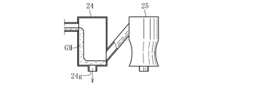
- the present inventors have applied the following method to a transfer device having a plurality of (two in the illustrated example) stirring pots 21 and 22 and a cooling pipe 23 as transfer containers. Tried.
- the molten glass is continuously discharged from the melting furnace to the transfer channel, and the discharged molten glass GM is continuously discharged only from the drain hole 22g of the stirring pot 22 on the downstream side as shown in FIG. It is like that.
- the present invention when the transfer device includes a plurality of transfer containers, the condition of each transfer container at the time of replacement of the forming means is good, so that the molten glass can be properly transferred at the time of restart.
- the task is to
- the present invention created to solve the above-described problems is directed to a transfer apparatus including a melting step of heating and melting glass raw materials in a melting furnace to generate molten glass, and a plurality of transfer containers each having an inlet and an outlet.
- a method of manufacturing a glass article wherein, in the exchanging step, while the forming step is interrupted, some of the plurality of transfer containers are brought into a state of holding molten glass, and the remaining It is characterized in that the transfer container is discharged so that it does not hold the molten glass and is brought into a temperature lowered state.
- the transfer device has, as the plurality of transfer containers, a stirring pot and a cooling pipe adjacent to a downstream side of the stirring pot, and in the exchange step, an outlet of the stirring pot in the transfer device. It is preferable that the upstream portion is in a state where the molten glass is retained, and the downstream portion of the cooling pipe in the transfer device is discharged so as not to retain the molten glass and the temperature is lowered. .
- the portion of the transfer device upstream of the outlet of the stirring pot in the transfer device holds the molten glass and does not go into the empty cooking state. Further, a portion of the transfer device downstream of the inlet of the cooling pipe is discharged so as not to hold the molten glass and is in a temperature-lowered state.
- the upstream side and the downstream side only distinguish between the presence or absence of the molten glass and the presence or absence of a temperature drop, and oxidize and re-react at both parts. Foreign matter can be prevented from entering the molten glass during operation. As a result, it is possible to easily perform temperature management, molten glass possession management, and the like over the entire length of the transfer channel.
- the transfer device include a plurality of the stirring pots as the plurality of transfer containers.
- the stirring pot 25 on the downstream side becomes empty, so that there is no internal pressure due to the molten glass GM. Therefore, after a while, as shown in FIG. 9B, a deformation occurs in which the peripheral wall of the downstream stirring pot 25 is depressed inward. As a result, even if an attempt is made to insert the stirring blade (stirrer) into the downstream stirring pot 25, it may be impossible to insert the stirring blade due to the above-mentioned deformation. The reason that such a problem becomes apparent is that only a small gap is provided between the outer peripheral end of the stirring blade and the inner peripheral surface of the stirring pot, so that even if the above deformation is slight, This is because the stirring blade cannot be inserted. In contrast, in the method according to the present invention, all of the plurality of stirring pots hold the molten glass, and there is no stirring pot that is empty. Therefore, the above-mentioned deformation does not occur in any of the stirring pots.
- the cooling pipe interrupts the molten glass at an outlet of the adjacent stirring pot, and discharges the molten glass from a drain hole opened on the inner bottom surface of the stirring pot. It is preferable to keep the state.
- the molten glass constantly flows in the stirring pot while the liquid level of the molten glass in the stirring pot is maintained at a desired height. Accordingly, the portion of the transfer device upstream of the stirring pot is always in a state of flowing while retaining the molten glass.
- the molten glass may be boiled down and may be transformed into a foreign glass.
- the molten glass always flows at a position upstream of the outlet of the stirring pot in the transfer device. For this reason, in this upstream portion, it is possible to prevent the molten glass from being changed into a foreign glass.
- the replacement of the forming means can be performed without any trouble.
- the flow passage area of the drain hole is smaller than the flow passage area of the outlet of the stirring pot.
- the molten pipe is discharged from a drain hole opened on the inner bottom surface of the nearest transfer container located on the upstream side of the stirring pot adjacent to the cooling pipe, so that the stirring pot is substantially empty.
- the blocking of the molten glass is performed by disposing a blocking member at the outlet of the stirring pot in this state, and thereafter, the stirring pot is preferably in a state of holding the molten glass.
- the stirring pot and the cooling pipe are made substantially empty by discharging the molten glass from a drain hole opened on the inner bottom surface of the transfer container. In this state, the stirring pot and the cooling pipe are cooled. It is preferable to separate the molten glass and then to perform the damming of the molten glass.
- the molten glass can be separated from both the stirring pot and the cooling pipe without leaking the molten glass. Thereby, the work of blocking the outlet of the stirring pot can be performed safely and smoothly.
- the temperature of the molten glass in the transfer container is lower than the temperature during operation.
- the flow speed of the molten glass in the plurality of transfer containers is appropriately reduced.
- the operation for holding and discharging the molten glass in each transfer container can be smoothly performed while finely adjusting the operation.
- the transfer device when the transfer device includes a plurality of transfer containers, the state of each transfer container at the time of replacement of the forming means is good, and the transfer of the molten glass can be appropriately performed at the time of restart.
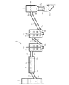
- BRIEF DESCRIPTION OF THE DRAWINGS It is a longitudinal side view which shows the transfer apparatus which is the principal part of the manufacturing apparatus for implementing the manufacturing method of the glass article which concerns on embodiment of this invention.
- It is a principal part schematic side view which shows the state which is performing the exchange process in the manufacturing method of the glass article which concerns on embodiment of this invention.
- It is a principal part schematic longitudinal side view which shows the state which is performing the replacement process in the manufacturing method of the glass article which concerns on embodiment of this invention.
- FIG. 1 illustrates an apparatus for producing a glass article used for carrying out the method according to the present invention.
- the manufacturing apparatus 1 is roughly divided into a melting furnace 2 which is provided at an upstream end and heats and melts a glass raw material, and transfers the molten glass flowing out of the melting furnace 2 toward a downstream side.
- the apparatus includes a transfer device 3 and forming means 4 for forming the molten glass Gm supplied from the transfer device 3 into a band-shaped plate glass Gp.
- the transfer device 3 has a fining pipe 5, a plurality of (two in the illustrated example) stirring pots 6 and 7, a cooling pipe 8, and a pot 9 in order from the upstream side as a transfer container.
- Each of these transfer containers 5 to 9 has an inlet into which the molten glass Gm flows, and an outlet through which the molten glass Gm flows out.
- the fining pipe 5 is for removing air bubbles in the molten glass
- the downstream side of the fining pipe 5 is provided with a first stirring pot 6 on the upstream side for homogenizing the molten glass and a second stirring pot on the downstream side.
- a pot 7 is provided.
- the stirring pots 6 and 7 accommodate stirring blades (stirrers) 6x and 7x that rotate around the axis.
- a cooling pipe 8 is disposed adjacently, and on the downstream side of the cooling pipe 8, a pot 9 serving as a volume part for mainly adjusting the viscosity of the molten glass is disposed adjacently. ing.
- the downstream side of the cooling pipe 8 is inclined upward.
- the forming means 4 has a formed body 10 that performs a forming operation by flowing down the molten glass by an overflow down draw method, and a large-diameter introduction pipe 11 that guides the molten glass GM to the formed body 10.
- the molten glass Gm is supplied to the introduction pipe 11 from the pot 9 of the transfer device 3.
- FIG. 2 is an enlarged vertical sectional view of the transfer device 3.
- the outflow port 2 b of the melting furnace 2 communicates with the inflow port 5 a of the fining pipe 5 via the upstream connection pipe 12.
- the outlet 5b of the fining pipe 5 communicates with the inlet 6a of the first stirring pot 6 via the intermediate connection pipe 13.
- the inflow port 6a of the first stirring pot 6 is provided at an upper portion of its peripheral wall.
- the outlet 6b of the first stirring pot 6 communicates with the inlet 7a of the second stirring pot 7 via the downstream connection pipe 14.
- the outlet 6b of the first stirring pot 6 is provided at a lower portion of the peripheral wall, and the inlet 7a of the second stirring pot 7 is provided at an upper portion of the peripheral wall.
- the downstream connection pipe 14 has a downstream side inclined upward.
- the outlet 7b of the second stirring pot 7 overlaps and communicates with the inlet 8a of the cooling pipe 8.
- the outlet 7b of the second stirring pot 7 is provided at a lower portion of the peripheral wall.
- the downstream side of the cooling pipe 8 is inclined upward.
- the outlet 8b of the cooling pipe 8 overlaps and communicates with the inlet 9a of the pot 9.
- the pot 9 has an upper large-diameter portion 9x and a lower small-diameter portion 9y.
- the inlet 9a of the pot 9 is provided on the peripheral wall of the large diameter portion 9x, and the outlet 9b is provided at the lower end of the small diameter portion 9y.
- the small diameter portion 9y of the pot 9 is inserted into the introduction pipe 11 of the forming means 4. The lower end of the small diameter portion 9y is immersed in the molten glass Gm in the introduction pipe 11.
- the transfer channel constituted by the transfer containers 5 to 9 and the connection pipes 12 to 14 at least a portion (in this embodiment, the entire inner surface of the transfer channel) in contact with the molten glass Gm has a thin noble metal (for example, it is formed of a member made of platinum or a platinum alloy. The periphery of those members is covered with a refractory (not shown).
- the transfer flow path is electrically heated so that the temperature can be adjusted for each of the transfer containers 5 to 9 and each of the connection pipes 12 to 14.
- the manufacturing apparatus 1 having the above configuration executes the following steps. That is, in the method for manufacturing a glass article according to the present invention, the melting step of heating and melting the glass raw material in the melting furnace 2 to generate the molten glass Gm, and transferring the molten glass Gm flowing out of the melting furnace 2 by the transfer device 3. A transfer step and a forming step of forming the molten glass Gm supplied from the transfer device 3 into a predetermined shape by the forming means 4 are provided. Further, this manufacturing method has an exchange step of exchanging the molding means 4. In the replacement process, the following is performed while the molding process is interrupted.
- the forming means 4 is separated from the transfer device 3 and separated as shown in FIG. In this state, the introduction pipe 11 of the molding means 4 is separated from the pot 9 of the transfer device 3, and the outlet 9b of the pot 9 is open to the outside air.
- FIG. 4 illustrates a state of the transfer device 3 during a period in which the replacement process is being performed.
- the transfer device 3 is separated at the boundary between the second stirring pot 7 and the cooling pipe 8. More specifically, the outlet 7b of the second stirring pot 7 is closed by the damming member 15, and the outflow of the molten glass Gm from the outlet 7b is prevented.
- the cooling pipe 8 is cut off from the second stirring pot 7, and its inflow port 8a is open to the outside air.
- the drain hole 7g opening on the inner bottom surface of the second stirring pot 7 is opened, and the molten glass Gm continues to be discharged downward through the drain hole 7g.
- the drain hole 6g opening on the inner bottom surface of the first stirring pot 6 is closed.
- the rotating blades 6x, 7x are removed from the first stirring pot 6 and the second stirring pot 7, but the rotating blades 6x, 7x may be attached.
- the molten glass Gm flows out of the melting furnace 2 continuously.
- the molten glass Gm that has flowed out flows through the fining pipe 5 and the first stirring pot 6, flows into the second stirring pot 7, and is discharged downward from the drain hole 7g.
- the flow passage area of the drain hole 6g of the first stirring pot 6 is smaller than the flow passage area of each of the inlet 6a and the outlet 6b of the first stirring pot 6.
- the flow passage area of the drain hole 7g of the second stirring pot 7 is smaller than the flow passage area of each of the inlet 7a and the outlet 7b of the second stirring pot 7.
- the flow rate of the molten glass Gm discharged from the drain hole 7g of the second stirring pot 7 can be easily adjusted.
- the molten glass Gm is discharged intermittently as droplets from the drain holes 7g, but the molten glass Gm may be discharged continuously as linear lines from the drain holes 7g.
- the fining pipe 5, the first stirring pot 6, and the second stirring pot 7 are all maintained in a state of holding the molten glass Gm.
- “holding the molten glass Gm” means that the liquid level height h1 (mm) of the molten glass Gm in each of the transfer containers 5 to 7 in the exchange process is determined when the manufacturing apparatus 1 is in operation (execution of the forming process).
- h1 / h0 can be 50% to 150%, preferably 75% to 125%, and more preferably 90 to 110%.
- the temperature of the molten glass Gm held by each of the transfer containers 5 to 7 is lower than the temperature of the molten glass held by each of the transfer containers 5 to 7 when the manufacturing apparatus 1 is operating, for example. It is set low by 25-150 ° C. Therefore, the flow rate of the molten glass Gm is appropriately reduced. As a result, possession and discharge of the molten glass Gm can be easily controlled.
- the temperature of the cooling pipe 8 is lowered as quickly as possible (for example, the temperature is lowered to room temperature). Further, the temperature of the pot 9 is also lowered as soon as possible after discharging the molten glass Gm (for example, the temperature is lowered to room temperature). Due to this temperature drop, the cooling pipe 8 and the pot 9 are not put in an empty state, and their oxidation is suppressed.
- the transfer container is discharged so as not to hold the molten glass and the temperature is lowered
- the temperature may be reduced to a temperature at which the oxidation of the noble metal constituting the transfer container is suppressed, and in this embodiment,
- the present invention is not limited to the case where the temperature of the transfer container is lowered until it reaches room temperature.
- the temperature is preferably lowered to 600 ° C. or lower, more preferably 300 ° C. or lower. From the viewpoint of reducing energy costs, it is preferable to lower the temperature to normal temperature.
- the above-described temperature reduction may be performed, for example, by allowing the transfer container to cool while the energization heating of the transfer container is stopped.
- the transfer container may be cooled using a fan or the like in a state in which the energization heating of the transfer container is stopped.
- the transfer container does not hold the molten glass means that all or most of the molten glass is discharged from the transfer container. That is, this includes a state in which a part of the molten glass remains in the transfer container.
- the mass of the molten glass held in the transfer container when the manufacturing apparatus 1 is operated (when the forming process is performed) is defined as m0 (kg), and the mass of the molten glass remaining after most of the molten glass is discharged from the transfer container.
- the portion A1 on the upstream side of the outlet 7b of the second stirring pot 7 in the transfer device 3 is in a state where the molten glass Gm is held while flowing. Further, a portion A2 downstream of the inlet 8a of the cooling pipe 8 in the transfer device 3 is discharged so as not to retain the molten glass Gm, and the temperature is lowered.
- the molten glass Gm is caused to flow not only in the fining pipe 5, the first stirring pot 6, and the second stirring pot 7 which are the transfer containers in the above example, but also in each of the connection pipes 12 to 14. While holding. Therefore, in this embodiment, the connection pipes 12 to 14 also belong to the class of the transfer container.
- FIG. 5 a shows the state at the start of the separation of the second stirring pot 7 and the cooling pipe 8.
- the forming means 4 is connected to the transfer device 3.
- the first stirring pot 6, the second stirring pot 7, and the cooling pipe 8 are in a state of holding the molten glass Gm.
- the three connection pipes 12 to 14 also hold the molten glass Gm.
- the molten glass G is discharged by opening the drain hole 6g of the first stirring pot 6 and the drain hole 7g of the second stirring pot 7, as shown in FIG.
- the supply of the molten glass to the first stirring pot 6 is stopped or reduced.
- the first stirring pot 6, the downstream connection pipe 14, the second stirring pot 7, the cooling pipe 8, the pot 9, and the introduction pipe 11 are substantially empty.
- the first stirring pot 6 and the downstream connection pipe 14 do not need to be substantially empty, and the liquid of the molten glass Gm can be suppressed to such an extent that the flow of the molten glass Gm into the second stirring pot 7 can be suppressed.
- the surface may be in a lowered state.
- the “substantially empty state” means the following state.
- the second stirring pot 7 in addition to the case where the internal space is completely empty, the case where the molten glass Gm remains and the liquid level thereof is lower than the lower end of the outlet 7b is also possible.
- the cooling pipe 8 includes a case where the internal flow path is completely empty and a case where the molten glass Gm slightly remains at the bottom of the internal flow path.
- the pot 9 also includes a case where the molten glass Gm slightly remains in a constricted portion of the internal space, in addition to a case where the internal space is completely empty.
- the first stirring pot 6 and the second stirring pot 7 hold the molten glass Gm. It is preferable that the temperature of the first stirring pot 6 and the second stirring pot 7 be maintained at a high temperature from the viewpoint of preventing deformation of the first stirring pot 6 and the second stirring pot 7 until the state is reached. At this time, the oxidation of the first stirring pot 6 and the second stirring pot 7 slightly progresses, but the oxidation is slight, and the generated platinum dust or the like is generated by the drain hole 6 g of the first stirring pot 6 or the second stirring pot 7. Is discharged from the drain hole 7g, so that the quality of the glass article is not substantially deteriorated.
- the most downstream stirring pot 18 and the cooling pipe 8 are connected.
- the procedure for disconnecting is as follows. That is, the most downstream stirring pot 18 performs the same operation as the above-described second stirring pot 7, and the nearest stirring pot 17 located on the upstream side of the most downstream stirring pot 18 performs the above-described operation. The same operation as that of the first stirring pot 6 is performed.
- the drain hole 16g of the stirring pot 16 located on the upstream side thereof is always kept closed.
- the outflow port 18b of the most downstream stirring pot 18 is closed by the dam member, and the molten glass Gm is continuously discharged only from the drain hole 18g.
- FIG. 7A and 7B illustrate a procedure for separating the stirring pot 19 and the cooling pipe 8 when the number of the stirring pot 19 is one.
- FIG. 7a illustrates the mode at the start of the separation of the two 19,8.
- the molten glass Gm starts to be discharged from the drain hole 19g of the stirring pot 19 from the state where the stirring pot 19 and the cooling pipe 8 hold the molten glass Gm.
- the flow rate of the molten glass Gm flowing into the stirring pot 19 has decreased. Therefore, as shown in FIG. 7B, the stirring pot 19 and the cooling pipe 8 are substantially empty.
- the “substantially empty state” here has the same meaning as described above.
- the molten glass Gm remains in the stirring pot 19, but the liquid level is lower than the outlet 19 b. Is lower than the lower end.
- the stirring pot 19 and the cooling pipe 8 are separated.
- the outlet 19b of the stirring pot 19 is closed by the dam member 20.
- the flow rate of the molten glass Gm flowing into the stirring pot 19 is increased.
- the upstream portion of the stirring pot 19 in the transfer device 3 is in a state where the molten glass Gm is held while flowing. Adjustment of the flow rate of the molten glass Gm flowing into the stirring pot 19 is performed by, for example, the fining pipe 5 and the intermediate connection pipe 13.
- the present invention is not limited to the above embodiment, and various variations are possible as exemplified below.
- the present invention can be similarly applied.
- the molten glass is continuously discharged from the drain hole of the stirring pot located on the most downstream side, so that the upstream side portion is held while flowing the molten glass.
- the molten glass may be continuously discharged from the outlet of the pot or both the outlet and the drain hole.
- the upstream-side portion and the downstream-side portion are divided with the boundary between the most downstream stirring pot and the cooling pipe as a boundary.
- the boundary between the transfer containers may be used.
- the cooling pipe may be divided into an upstream portion and a downstream portion with a boundary between the cooling pipe and the pot, and a blocking member may be disposed at an outlet of the cooling pipe.
- a blocking member may be disposed at an outlet of the cooling pipe.
- the molten glass is continuously discharged from any of the transport containers, so that the required transport container holds the molten glass while flowing the molten glass.
- the transfer container can be prevented from being oxidized.
- the upstream transfer section and the downstream transfer section are divided as the only boundary between the adjacent transfer containers.However, the transfer container holding the molten glass, and the discharge is performed so as not to hold the molten glass. As long as there is a transfer container in a state where the temperature is lowered, the number of the parts to be divided and the number of the parts to be divided are not particularly limited.
- the forming means is for forming a band-shaped plate glass, but may be for forming a glass sheet into another shape corresponding to the glass article.
Landscapes
- Chemical & Material Sciences (AREA)
- Engineering & Computer Science (AREA)
- Materials Engineering (AREA)
- Organic Chemistry (AREA)
- Glass Melting And Manufacturing (AREA)
- Glass Compositions (AREA)
- Seal Device For Vehicle (AREA)
- Re-Forming, After-Treatment, Cutting And Transporting Of Glass Products (AREA)
Abstract
Description
2 溶融炉
3 移送装置
4 成形手段
5 清澄パイプ
5a 流入口
5b 流出口
6 攪拌ポット
6a 流入口
6b 流出口
6g ドレン孔
7 攪拌ポット
7a 流入口
7b 流出口
7g ドレン孔
8 冷却パイプ
8a 流入口
8b 流出口
9 ポット
9a 流入口
9b 流出口
10 成形体
15 堰き止め部材
16 攪拌ポット
16g ドレン孔
17 攪拌ポット
18 攪拌ポット
19 攪拌ポット
20 堰き止め部材
A1 上流側部位
A2 下流側部位
Gm 溶融ガラス
Claims (8)
- 溶融炉でガラス原料を加熱溶融して溶融ガラスを生成する溶融工程と、流入口と流出口とをそれぞれ有する複数の移送容器を含む移送装置によって前記溶融炉から流出した溶融ガラスを移送する移送工程と、前記移送装置から供給された溶融ガラスを成形手段によって所定形状に成形する成形工程と、前記成形手段を交換する交換工程と、を備えたガラス物品の製造方法であって、
前記交換工程では、前記成形工程を中断した状態で、前記複数の移送容器のうちの一部の移送容器が溶融ガラスを保有した状態にすると共に、残りの移送容器が溶融ガラスを保有しないように排出して降温した状態にすることを特徴とするガラス物品の製造方法。 - 前記移送装置は、前記複数の移送容器として、攪拌ポットと、該攪拌ポットの下流側に隣接する冷却パイプとを有し、
前記交換工程では、前記移送装置における前記攪拌ポットの流出口よりも上流側部位が溶融ガラスを保有した状態にすると共に、前記移送装置における前記冷却パイプの流入口よりも下流側部位が溶融ガラスを保有しないように排出して降温した状態にすることを特徴とする請求項1に記載のガラス物品の製造方法。 - 前記移送装置は、前記複数の移送容器として、前記攪拌ポットを複数有することを特徴とする請求項2に記載のガラス物品の製造方法。
- 前記冷却パイプが隣接する前記攪拌ポットの流出口で溶融ガラスを堰き止めると共に、該攪拌ポットの内底面に開口するドレン孔から溶融ガラスを排出しつつ該攪拌ポットが溶融ガラスを保有した状態にすることを特徴とする請求項2または3に記載のガラス物品の製造方法。
- 前記攪拌ポットの流出口の流路面積よりも前記ドレン孔の流路面積の方が小さいことを特徴とする請求項4に記載のガラス物品の製造方法。
- 前記冷却パイプが隣接する前記攪拌ポットの上流側に位置する直近の移送容器の内底面に開口するドレン孔から溶融ガラスを排出させることで、該攪拌ポットを実質的に空の状態にし、この状態で該攪拌ポットの流出口に堰き止め部材を配置することで、溶融ガラスの前記堰き止めを行い、その後に、該攪拌ポットが溶融ガラスを保有した状態にすることを特徴とする請求項4または5に記載のガラス物品の製造方法。
- 前記移送容器の内底面に開口するドレン孔から溶融ガラスを排出させることで、前記攪拌ポットと前記冷却パイプとを実質的に空の状態にし、この状態で該攪拌ポットと該冷却パイプとを分離させ、然る後、溶融ガラスの前記堰き止めを行うことを特徴とする請求項6に記載のガラス物品の製造方法。
- 前記交換工程では、前記移送容器内の溶融ガラスの温度を操業時の温度よりも低下させることを特徴とする請求項1~7の何れかに記載のガラス物品の製造方法。
Priority Applications (3)
| Application Number | Priority Date | Filing Date | Title |
|---|---|---|---|
| KR1020207026415A KR102612688B1 (ko) | 2018-06-25 | 2019-06-18 | 유리 물품의 제조 방법 |
| JP2020527428A JP7167984B2 (ja) | 2018-06-25 | 2019-06-18 | ガラス物品の製造方法 |
| CN201980033227.7A CN112135800B (zh) | 2018-06-25 | 2019-06-18 | 玻璃物品的制造方法 |
Applications Claiming Priority (2)
| Application Number | Priority Date | Filing Date | Title |
|---|---|---|---|
| JP2018-119952 | 2018-06-25 | ||
| JP2018119952 | 2018-06-25 |
Publications (1)
| Publication Number | Publication Date |
|---|---|
| WO2020004143A1 true WO2020004143A1 (ja) | 2020-01-02 |
Family
ID=68986547
Family Applications (1)
| Application Number | Title | Priority Date | Filing Date |
|---|---|---|---|
| PCT/JP2019/024094 Ceased WO2020004143A1 (ja) | 2018-06-25 | 2019-06-18 | ガラス物品の製造方法 |
Country Status (5)
| Country | Link |
|---|---|
| JP (1) | JP7167984B2 (ja) |
| KR (1) | KR102612688B1 (ja) |
| CN (1) | CN112135800B (ja) |
| TW (1) | TWI814846B (ja) |
| WO (1) | WO2020004143A1 (ja) |
Citations (2)
| Publication number | Priority date | Publication date | Assignee | Title |
|---|---|---|---|---|
| JP2004262745A (ja) * | 2003-02-10 | 2004-09-24 | Nippon Electric Glass Co Ltd | 溶融ガラス供給装置 |
| JP2013512184A (ja) * | 2009-11-30 | 2013-04-11 | コーニング インコーポレイテッド | ガラス製造工程における凝縮物に関連する欠陥を減少させるための方法および装置 |
Family Cites Families (8)
| Publication number | Priority date | Publication date | Assignee | Title |
|---|---|---|---|---|
| JP2002167226A (ja) | 2000-11-29 | 2002-06-11 | Asahi Glass Co Ltd | 薄板ガラスの製造装置 |
| TW201116496A (en) * | 2003-02-10 | 2011-05-16 | Nippon Electric Glass Co | Molten glass supply device, glass formed product, and method of producing the glass formed product |
| KR101306065B1 (ko) * | 2006-01-05 | 2013-09-09 | 니폰 덴키 가라스 가부시키가이샤 | 용융 유리 공급 장치 및 유리 성형품의 제조 방법 |
| CN101935146B (zh) * | 2010-03-24 | 2012-07-04 | 东旭集团有限公司 | 铂金通道中玻璃液的处理方法 |
| WO2013073059A1 (ja) * | 2011-11-18 | 2013-05-23 | AvanStrate株式会社 | ガラスの製造方法、および、攪拌装置 |
| JP2014019629A (ja) * | 2012-07-20 | 2014-02-03 | Nippon Electric Glass Co Ltd | ガラス板製造装置及びその組立方法 |
| JP2014094843A (ja) * | 2012-11-07 | 2014-05-22 | Nippon Electric Glass Co Ltd | 溶融ガラス移送装置 |
| JP6110448B2 (ja) * | 2014-09-30 | 2017-04-05 | AvanStrate株式会社 | ガラス基板の製造方法、及び、攪拌装置 |
-
2019
- 2019-06-18 CN CN201980033227.7A patent/CN112135800B/zh active Active
- 2019-06-18 WO PCT/JP2019/024094 patent/WO2020004143A1/ja not_active Ceased
- 2019-06-18 KR KR1020207026415A patent/KR102612688B1/ko active Active
- 2019-06-18 JP JP2020527428A patent/JP7167984B2/ja active Active
- 2019-06-24 TW TW108121877A patent/TWI814846B/zh active
Patent Citations (2)
| Publication number | Priority date | Publication date | Assignee | Title |
|---|---|---|---|---|
| JP2004262745A (ja) * | 2003-02-10 | 2004-09-24 | Nippon Electric Glass Co Ltd | 溶融ガラス供給装置 |
| JP2013512184A (ja) * | 2009-11-30 | 2013-04-11 | コーニング インコーポレイテッド | ガラス製造工程における凝縮物に関連する欠陥を減少させるための方法および装置 |
Also Published As
| Publication number | Publication date |
|---|---|
| JP7167984B2 (ja) | 2022-11-09 |
| JPWO2020004143A1 (ja) | 2021-07-08 |
| KR20210022523A (ko) | 2021-03-03 |
| KR102612688B1 (ko) | 2023-12-12 |
| TWI814846B (zh) | 2023-09-11 |
| TW202012320A (zh) | 2020-04-01 |
| CN112135800B (zh) | 2022-08-23 |
| CN112135800A (zh) | 2020-12-25 |
Similar Documents
| Publication | Publication Date | Title |
|---|---|---|
| CN101506110B (zh) | 熔融玻璃的导管结构及采用该导管结构的减压脱泡装置 | |
| TWI408110B (zh) | 製造浮玻璃用之浮浴系統及其冷卻方法 | |
| KR101141231B1 (ko) | 용융유리 공급장치, 유리제품, 및 유리제품 제조방법 | |
| JP7223345B2 (ja) | ガラス物品の製造方法、製造装置及びガラス基板 | |
| JP7138843B2 (ja) | ガラス物品の製造方法 | |
| JP7167984B2 (ja) | ガラス物品の製造方法 | |
| CN112912348A (zh) | 玻璃物品的制造方法 | |
| CN113874331B (zh) | 玻璃物品的制造装置以及制造方法 | |
| CN113677634B (zh) | 玻璃移送装置 | |
| JP7063153B2 (ja) | ガラス物品の製造方法 | |
| JP7255337B2 (ja) | ガラス板の製造装置 | |
| CN109982979B (zh) | 板玻璃制造方法、澄清容器以及板玻璃制造装置 | |
| JP7547888B2 (ja) | ガラス板の製造方法及びその製造装置。 | |
| JP7810955B2 (ja) | ガラス物品の製造方法 | |
| TW201529504A (zh) | 玻璃液供應系統 | |
| WO2024038740A1 (ja) | ガラス物品の製造方法及びガラス物品の製造装置 | |
| WO2026034174A1 (ja) | ガラス物品の製造方法及びガラス物品の製造装置 | |
| WO2023100688A1 (ja) | ガラス物品の製造方法 | |
| JP2026054079A (ja) | ガラス物品の製造方法、及びガラス物品の製造装置 | |
| WO2023234083A1 (ja) | ガラス物品の製造装置及びガラス物品の製造方法 | |
| WO2024219246A1 (ja) | 清澄装置、ガラス物品の製造方法、及び管状部材 | |
| CN118139826A (zh) | 熔融玻璃移送装置、玻璃物品的制造装置以及玻璃物品的制造方法 | |
| TWM478686U (zh) | 玻璃液供應系統 |
Legal Events
| Date | Code | Title | Description |
|---|---|---|---|
| 121 | Ep: the epo has been informed by wipo that ep was designated in this application |
Ref document number: 19825383 Country of ref document: EP Kind code of ref document: A1 |
|
| ENP | Entry into the national phase |
Ref document number: 2020527428 Country of ref document: JP Kind code of ref document: A |
|
| ENP | Entry into the national phase |
Ref document number: 20207026415 Country of ref document: KR Kind code of ref document: A |
|
| NENP | Non-entry into the national phase |
Ref country code: DE |
|
| 122 | Ep: pct application non-entry in european phase |
Ref document number: 19825383 Country of ref document: EP Kind code of ref document: A1 |