WO2020004039A1 - 電池モジュール用緩衝シート - Google Patents
電池モジュール用緩衝シート Download PDFInfo
- Publication number
- WO2020004039A1 WO2020004039A1 PCT/JP2019/023306 JP2019023306W WO2020004039A1 WO 2020004039 A1 WO2020004039 A1 WO 2020004039A1 JP 2019023306 W JP2019023306 W JP 2019023306W WO 2020004039 A1 WO2020004039 A1 WO 2020004039A1
- Authority
- WO
- WIPO (PCT)
- Prior art keywords
- elastic
- battery cell
- buffer sheet
- battery
- target surface
- Prior art date
Links
Images


Classifications
-
- H—ELECTRICITY
- H01—ELECTRIC ELEMENTS
- H01M—PROCESSES OR MEANS, e.g. BATTERIES, FOR THE DIRECT CONVERSION OF CHEMICAL ENERGY INTO ELECTRICAL ENERGY
- H01M50/00—Constructional details or processes of manufacture of the non-active parts of electrochemical cells other than fuel cells, e.g. hybrid cells
- H01M50/20—Mountings; Secondary casings or frames; Racks, modules or packs; Suspension devices; Shock absorbers; Transport or carrying devices; Holders
- H01M50/204—Racks, modules or packs for multiple batteries or multiple cells
-
- H—ELECTRICITY
- H01—ELECTRIC ELEMENTS
- H01M—PROCESSES OR MEANS, e.g. BATTERIES, FOR THE DIRECT CONVERSION OF CHEMICAL ENERGY INTO ELECTRICAL ENERGY
- H01M10/00—Secondary cells; Manufacture thereof
- H01M10/04—Construction or manufacture in general
-
- H—ELECTRICITY
- H01—ELECTRIC ELEMENTS
- H01M—PROCESSES OR MEANS, e.g. BATTERIES, FOR THE DIRECT CONVERSION OF CHEMICAL ENERGY INTO ELECTRICAL ENERGY
- H01M10/00—Secondary cells; Manufacture thereof
- H01M10/60—Heating or cooling; Temperature control
- H01M10/61—Types of temperature control
- H01M10/613—Cooling or keeping cold
-
- H—ELECTRICITY
- H01—ELECTRIC ELEMENTS
- H01M—PROCESSES OR MEANS, e.g. BATTERIES, FOR THE DIRECT CONVERSION OF CHEMICAL ENERGY INTO ELECTRICAL ENERGY
- H01M10/00—Secondary cells; Manufacture thereof
- H01M10/60—Heating or cooling; Temperature control
- H01M10/62—Heating or cooling; Temperature control specially adapted for specific applications
- H01M10/625—Vehicles
-
- H—ELECTRICITY
- H01—ELECTRIC ELEMENTS
- H01M—PROCESSES OR MEANS, e.g. BATTERIES, FOR THE DIRECT CONVERSION OF CHEMICAL ENERGY INTO ELECTRICAL ENERGY
- H01M10/00—Secondary cells; Manufacture thereof
- H01M10/60—Heating or cooling; Temperature control
- H01M10/64—Heating or cooling; Temperature control characterised by the shape of the cells
- H01M10/647—Prismatic or flat cells, e.g. pouch cells
-
- H—ELECTRICITY
- H01—ELECTRIC ELEMENTS
- H01M—PROCESSES OR MEANS, e.g. BATTERIES, FOR THE DIRECT CONVERSION OF CHEMICAL ENERGY INTO ELECTRICAL ENERGY
- H01M10/00—Secondary cells; Manufacture thereof
- H01M10/60—Heating or cooling; Temperature control
- H01M10/65—Means for temperature control structurally associated with the cells
- H01M10/655—Solid structures for heat exchange or heat conduction
- H01M10/6556—Solid parts with flow channel passages or pipes for heat exchange
- H01M10/6557—Solid parts with flow channel passages or pipes for heat exchange arranged between the cells
-
- H—ELECTRICITY
- H01—ELECTRIC ELEMENTS
- H01M—PROCESSES OR MEANS, e.g. BATTERIES, FOR THE DIRECT CONVERSION OF CHEMICAL ENERGY INTO ELECTRICAL ENERGY
- H01M10/00—Secondary cells; Manufacture thereof
- H01M10/60—Heating or cooling; Temperature control
- H01M10/65—Means for temperature control structurally associated with the cells
- H01M10/656—Means for temperature control structurally associated with the cells characterised by the type of heat-exchange fluid
- H01M10/6561—Gases
-
- H—ELECTRICITY
- H01—ELECTRIC ELEMENTS
- H01M—PROCESSES OR MEANS, e.g. BATTERIES, FOR THE DIRECT CONVERSION OF CHEMICAL ENERGY INTO ELECTRICAL ENERGY
- H01M50/00—Constructional details or processes of manufacture of the non-active parts of electrochemical cells other than fuel cells, e.g. hybrid cells
- H01M50/20—Mountings; Secondary casings or frames; Racks, modules or packs; Suspension devices; Shock absorbers; Transport or carrying devices; Holders
- H01M50/289—Mountings; Secondary casings or frames; Racks, modules or packs; Suspension devices; Shock absorbers; Transport or carrying devices; Holders characterised by spacing elements or positioning means within frames, racks or packs
-
- Y—GENERAL TAGGING OF NEW TECHNOLOGICAL DEVELOPMENTS; GENERAL TAGGING OF CROSS-SECTIONAL TECHNOLOGIES SPANNING OVER SEVERAL SECTIONS OF THE IPC; TECHNICAL SUBJECTS COVERED BY FORMER USPC CROSS-REFERENCE ART COLLECTIONS [XRACs] AND DIGESTS
- Y02—TECHNOLOGIES OR APPLICATIONS FOR MITIGATION OR ADAPTATION AGAINST CLIMATE CHANGE
- Y02E—REDUCTION OF GREENHOUSE GAS [GHG] EMISSIONS, RELATED TO ENERGY GENERATION, TRANSMISSION OR DISTRIBUTION
- Y02E60/00—Enabling technologies; Technologies with a potential or indirect contribution to GHG emissions mitigation
- Y02E60/10—Energy storage using batteries
-
- Y—GENERAL TAGGING OF NEW TECHNOLOGICAL DEVELOPMENTS; GENERAL TAGGING OF CROSS-SECTIONAL TECHNOLOGIES SPANNING OVER SEVERAL SECTIONS OF THE IPC; TECHNICAL SUBJECTS COVERED BY FORMER USPC CROSS-REFERENCE ART COLLECTIONS [XRACs] AND DIGESTS
- Y02—TECHNOLOGIES OR APPLICATIONS FOR MITIGATION OR ADAPTATION AGAINST CLIMATE CHANGE
- Y02P—CLIMATE CHANGE MITIGATION TECHNOLOGIES IN THE PRODUCTION OR PROCESSING OF GOODS
- Y02P70/00—Climate change mitigation technologies in the production process for final industrial or consumer products
- Y02P70/50—Manufacturing or production processes characterised by the final manufactured product
Definitions
- the present invention relates to a buffer sheet for a battery module.
- Battery modules are applied to automobiles and the like, and batteries have been increasing in energy density to extend the mileage. It is known that a battery cell expands due to heat generation due to charging due to higher energy density and contracts as discharging. It is also known that the battery deteriorates due to repetition of charge and discharge, does not shrink completely to the original shape at the time of discharge, and gradually shifts to the expansion side even at the time of discharge. Therefore, a structure in which a stacked body of a plurality of battery cells is restrained by a pair of restraining members from both ends of the stacked body is disclosed in Japanese Patent No. 51222898, Japanese Patent Application Laid-Open No. 2017-212120, Japanese Patent No. 6277787, and It is described in 2006-253149.
- a sheet-like elastic member is disposed between the battery cell and the restraining member. Further, in the battery cell, a contact portion with the adjacent battery cell is formed in a rib shape, so that cooling air flows between the adjacent battery cells. Further, in the battery module described in JP-A-2006-253149, a partition having a plurality of protrusions is arranged between adjacent battery cells in order to allow cooling air to flow between adjacent battery cells. I have.
- the object of the present invention is to provide a buffer sheet for a battery module, which is applied to a battery module and can reliably elastically support a battery cell during charging and reliably apply a reaction force when discharging the battery cell.
- the buffer sheet for a battery module is applied to a battery module including a stacked body of a plurality of battery cells and a pair of restraining members for restraining the stacked body from both ends in the stacking direction of the stacked body, and a target surface of the battery cell. It is interposed between the restraining members or between target surfaces of the adjacent battery cells.
- the battery module buffer sheet is formed of a plate-shaped base having a first surface separated from the target surface of the battery cell by an elastic material, and is formed of an elastic material.
- the battery cell is formed so as to protrude toward the target surface, is arranged in a plurality in a cross section orthogonal to the target surface of the battery cell, and has a trapezoidal cross section in the arrangement direction, and has a curved shape accompanying the charging of the battery cell.
- An elastic protrusion that elastically supports the battery cell when expanded and applies a reaction force to the battery cell when contracted due to discharge of the battery cell.
- the cross-sectional shape of the elastic protrusions in the arrangement direction is a trapezoidal top that contacts the target surface of the battery cell, and a side that connects the trapezoidal top and the base, and is a buffer sheet for the battery module. And an outer trapezoidal hypotenuse facing outward in the arrangement direction.
- the target of the battery cell with respect to the stacking reference when the stacking direction of the battery cell is set as the stacking reference.
- the acute angle of inclination of the normal to the surface is defined as ⁇ . Then, it is set so as to satisfy the relationship of Expression (1). ⁇ a ⁇ ⁇ (1)
- the normal line of the target surface of the battery cell at the time of full charge is present inside the trapezoidal elastic protrusion at the portion where the predetermined elastic protrusion comes into contact with the target surface of the battery cell.
- the line of force that the elastic protrusion receives from the target surface of the battery cell is present inside the elastic protrusion. Therefore, when the target surface of the battery cell expands in a curved convex shape at the time of full charge, even if the elastic protrusion receives a force from the target surface of the battery cell, the elastic protrusion is only compressed, It is possible to prevent bending and falling.
- the elastic projections of the battery module buffer sheet can reliably support the elasticity when the battery cell is fully charged, and can reliably apply a reaction force when the battery cell is discharged.
- FIG. 6B is a cross-sectional view of the target surface of the battery cell in FIG. 6A.
- FIG. 6A It is sectional drawing of the buffer sheet in FIG. 6A. It is a perspective view of the 1st buffer sheet of a 2nd example. It is a perspective view of the 1st buffer sheet of the 3rd example. It is a perspective view of the 1st buffer sheet of the 4th example. It is a perspective view of the 1st buffer sheet of the 5th example. It is a figure of the 2nd buffer sheet of the first example.
- the battery module 1 of the first example will be described with reference to FIGS. As shown in FIG. 1, the battery module 1 is used, for example, as a battery of an automobile.
- the battery module 1 includes a stacked body 12 in which a plurality of battery cells 11 are stacked, a restraining member 13, and a first buffer sheet 14.
- Each of the battery cells 11 constituting the stacked body 12 is formed in a rectangular parallelepiped flat shape.
- the stacked body 12 is formed by stacking flat battery cells 11 in a direction (flat normal direction) orthogonal to the flat surface direction.
- the battery cell 11 is a secondary battery capable of charging and discharging power, and for example, a lithium ion secondary battery or the like is suitably used.
- the battery cell 11 includes a housing 11a formed in a rectangular parallelepiped flat box shape, and an electrode body 11b wound inside the housing 11a.
- the housing 11a is made of, for example, a metal such as aluminum or a hard resin.
- a surface of the housing 11a that is orthogonal to the flat surface direction is referred to as a target surface 11a1.
- the electrode body 11b includes a positive electrode, a negative electrode, and a separator sandwiched between the positive electrode and the negative electrode, and is wound in a flat shape.
- the electrode body 11b expands mainly in the direction of the flat normal line by generating heat with charging. Conversely, the electrode body 11b contracts with the discharge. Therefore, the housing 11a of the battery cell 11 that houses the electrode body 11b expands in the flat normal direction during charging.
- the housing 11a is formed in a rectangular parallelepiped flat box shape, the target surface 11a1 easily expands and deforms into a curved convex shape.
- the amount of expansion of the target surface 11a1 of the housing 11a becomes maximum.
- the target surface 11a1 of the housing 11a ideally returns to a planar shape as the electrode body 11b contracts.
- due to the deterioration of the electrode body 11b it does not gradually return to the original shape, and the battery performance decreases.
- the restraining member 13 restrains the stacked body 12 from both ends in the stacking direction of the stacked body 12. That is, the constraining member 13 returns the battery cell 11 to an initial state (non-expanded state) by applying a reaction force to each battery cell 11 when each battery cell 11 expands due to charging.
- the restraining member 13 includes a first restraining member 13a, a second restraining member 13b, and a connecting member 13c.
- the first restraining member 13a is formed in an L-shape, and includes a portion as a pedestal of the laminate 12 and a portion (end restraint portion) on the first end side (right side in FIG. 1) of the laminate 12. Be placed.
- the end constrained portion of the first constraining member 13a is arranged to face the target surface 11a1 of the battery cell 11 located at the first end of the stacked body 12. Further, the surface on the battery cell 11 side in the end constrained portion of the first constraining member 13a is formed in a planar shape.
- the second restraining member 13b is formed in a flat plate shape, and is arranged on the second end side (the left side in FIG. 1) opposite to the first end of the laminated body 12. Specifically, the second restraining member 13b is arranged to face the target surface 11a1 of the battery cell 11 located at the second end of the stacked body 12. Furthermore, the surface on the battery cell 11 side of the second restraining member 13b is formed in a planar shape.
- the stacked body 12 is sandwiched between the first restraining member 13a and the second restraining member 13b in the stacking direction.
- the connecting member 13c connects the first restraining member 13a and the second restraining member 13b.
- the members 13a, 13b, and 13c constituting the restraining member 13 are preferably made of metal in order to exhibit a sufficient restraining force, but hard resin can also be used.
- the first buffer sheet 14 is interposed between the target surface 11a1 of the battery cell 11 located at the second end of the stacked body 12 and the second restraining member 13b.
- the first buffer sheet 14 has the elastic body portion, thereby absorbing the deformation accompanying the expansion and contraction of the battery cell 11. Then, as shown in FIG. 1, the first buffer sheet 14 elastically supports the battery cells 11 when the battery cells 11 contract. Further, as shown in FIG. 2, the first buffer sheet 14 elastically supports the battery cell 11 when the battery cell 11 expands due to charging, and at the same time, contracts with the battery cell 11 when discharging the battery cell 11. Give reaction force.
- the first buffer sheet 14 having the elastic body portion suitably exhibits the above function.
- the first buffer sheet 14 includes a plate-shaped base portion 21 and an elastic protrusion 22.
- the first surface of the base portion 21 is arranged at a distance from the target surface 11a1 of the battery cell 11 located at the second end of the stacked body 12.
- the second surface of the base 21 contacts the second restraining member 13b.
- the elastic protrusion 22 is made of an elastic material, protrudes from the first surface of the base 21 in the surface normal direction, and contacts the target surface 11a1 of the battery cell 11.
- the elastic projection 22 elastically supports the battery cell 11 when the battery cell 11 expands in a curved convex shape due to charging. Further, the elastic protrusion 22 applies a reaction force to the battery cell 11 when the battery cell 11 contracts due to discharge.
- the battery module 2 of the second example will be described with reference to FIG.
- the battery module 2 includes a stacked body 12 in which a plurality of battery cells 11 are stacked, a restraining member 13, a first buffer sheet 14, and a second buffer sheet 15.
- the configuration other than the second buffer sheet 15 is the same as that of the battery module 1 of the first example, and thus the description is omitted.
- the second buffer sheet 15 is interposed between the target surfaces 11a1 and 11a1 of the two adjacent battery cells 11 and 11.
- the second buffer sheet 15, like the first buffer sheet 14, has an elastic body portion to absorb the deformation accompanying the expansion and contraction of the battery cell 11. That is, the second buffer sheet 15 elastically supports the battery cells 11 when the battery cells 11 expand due to charging, and applies a reaction force to the battery cells when the battery cells 11 contract due to discharging.
- the second buffer sheet 15 includes a plate-shaped base portion 31, a first elastic protrusion 32, and a second elastic protrusion 33.
- the first surface of the base portion 31 is arranged at a distance from the target surface 11a1 of one of the two adjacent battery cells 11, 11.
- the second surface of the base portion 31 is arranged at a distance from the target surface 11a1 of the other battery cell 11.
- the first elastic protrusion 32 is formed of an elastic material, protrudes from the first surface of the base 31 in the surface normal direction, and contacts the target surface 11a1 of one battery cell 11. Then, the first elastic protrusion 32 elastically supports the one battery cell 11 when the one battery cell 11 is in a curved convex expansion due to charging. Further, the first elastic projection 32 applies a reaction force to the one battery cell 11 when the one battery cell 11 contracts due to discharge.
- the second elastic projection 33 is formed of an elastic material, protrudes from the second surface of the base 31 in the surface normal direction, and contacts the target surface 11a1 of the other battery cell 11. Then, the second elastic projection 33 elastically supports the other battery cell 11 when the other battery cell 11 is in a curved convex expansion due to charging of the other battery cell 11. Further, the second elastic projection 33 applies a reaction force to the other battery cell 11 when the other battery cell 11 contracts due to discharge.
- FIG. 4 is a perspective view of the first buffer sheet 40
- FIG. 5 is a cross-sectional view of the first buffer sheet 40 in a state where the first buffer sheet 40 is not applied to the battery modules 1 and 2, that is, in a no-load state. is there.
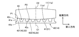
- the first buffer sheet 40 of the first example includes a base portion 41 and a plurality of elastic protrusions 42.
- the first buffer sheet 40 is formed integrally with a base portion 41 and an elastic protrusion 42, and is entirely formed of an elastomer as one of elastic materials.
- EPDM or the like is preferably used as an elastomer excellent in a low-temperature environment.
- the base portion 41 and the elastic protrusions 42 may be made of different materials and may be joined to each other.
- the base portion 41 may be formed of a metal plate such as aluminum
- the elastic protrusion 42 may be formed of an elastomer.
- the base portion 41 is formed in a flat plate shape, and has a first surface 41a separated from the target surface 11a1 of the battery cell 11 and a second surface 41b abutting on the second restraining member 13b. Since the base portion 41 is formed of an elastomer, the base portion 41 has flexibility when existing as the first buffer sheet 40 alone. However, in a state where the first buffer sheet 40 is applied to the battery modules 1 and 2, the second surface 41b of the base portion 41 is in contact with the second restraining member 13b. Is regulated along the surface shape of the second restraining member 13b. In the present embodiment, since the second restraining member 13b is formed in a planar shape, the base portion 41 has a flat plate shape.
- the plurality of elastic projections 42 are independent of each other, and are formed to project from the first surface 41 a of the base 41.
- the plurality of elastic projections 42 are formed in a ridge shape extending in the first direction. That is, the plurality of elastic protrusions 42 correspond to portions that are linearly raised in the first direction, and a slit 43 extending in the first direction is formed between the adjacent elastic protrusions 42. .
- the cross section of the first buffer sheet 40 orthogonal to the first direction in FIG. 4 and orthogonal to the target surface 11a1 (shown in FIG. 1) of the battery cell 11 is as shown in FIG. Therefore, in the cross section shown in FIG. 5, the plurality of elastic protrusions 42 are arranged in the second direction orthogonal to the first direction.
- the second direction is referred to as an arrangement direction
- the cross section illustrated in FIG. 5 is referred to as an arrangement direction cross section.
- the cross-sectional shape of the elastic projections 42 in the arrangement direction is formed in a trapezoidal shape as shown in FIG.
- the cross-sectional shape of the elastic protrusion 42 is formed in an equilateral trapezoidal shape.
- the cross-sectional shapes of the plurality of elastic projections 42 are formed in the same shape. However, as described later, the cross-sectional shapes of the plurality of elastic protrusions 42 may be formed in different shapes.
- the elastic projection 42 has a trapezoidal base 42a connected to the base 41, a trapezoidal top 42b abutting on the target surface 11a1 of the battery cell 11, and a side connecting the trapezoidal top 42b to the base 41 (trapezoidal base 42a).
- the outer trapezoidal oblique side 42c facing the outside in the arrangement direction of the first buffer sheet 40, and the side connecting the trapezoidal top side 42b and the base portion 41, and the center side in the arrangement direction of the first buffer sheet 40 is An inner trapezoidal hypotenuse 42d is provided.
- the projecting direction of the elastic projection 42 is defined as an elastic reference C1.
- the acute angle of inclination of the outer trapezoidal oblique side 42c with respect to the elasticity standard C1 in the elastic projection 42 is defined as ⁇ b.
- the acute acute angle ⁇ b of the outer trapezoidal oblique sides 42c in all the elastic projections 42 is the same.
- FIGS. 6A, 6B, and 6C show both the battery cell 11 and the first buffer sheet 40
- FIG. 6B shows only the battery cell 11 in FIG. 6A
- FIG. 6C shows only the first buffer sheet 40 in FIG. 6A.
- the battery cell 11 when the battery cell 11 is fully charged, the battery cell 11 is in the maximum expansion state. Specifically, the target surface 11a1 of the battery cell 11 expands and deforms in a curved convex shape. The target surface 11a1 expands and deforms into a substantially arc-shaped convex shape. Further, the stacked body 12 is configured by a plurality of battery cells 11. Therefore, when all the battery cells 11 are fully charged, the position of the target surface 11a1 of the battery cell 11 located at the second end slides toward the second restraining member 13b as compared with the time of discharging.
- the trapezoidal top 42b of the elastic projection 42 abuts on the target surface 11a1 of the battery cell 11, and the base 41 to which the trapezoidal bottom 42a of the elastic projection 42 is connected is restrained in a planar manner by the second restraining member 13b.
- the elastic projection 42 is in a state of receiving a compressive load, particularly, in a state of receiving the maximum compressive load when fully charged.
- the elastic protrusion 42 is compressed in the stacking direction of the stacked body 12, and the trapezoidal top side 42 b of the elastic protrusion 42 has a curved concave shape obtained by transferring the curved convex shape of the target surface 11 a 1 of the battery cell 11. Become.
- the deformation state of the elastic projection 42 differs depending on the position of the plurality of elastic projections 42 in the arrangement direction (second direction). Therefore, in the following description, among the plurality of elastic protrusions 42, the elastic protrusion 42 located outside in the arrangement direction (second direction) of the plurality of elastic protrusions 42 is referred to as an outer elastic protrusion 421, and the center side Is defined as an inner elastic projection 422.
- the stacking direction of the battery cells 11 is defined as a stacking reference C2. Then, when the plurality of elastic protrusions 42 are in the maximum compression load state, at the portion P of the target surface 11a1 of the battery cell 11 where the elastic protrusion 42 abuts, the target surface 11a1 of the battery cell 11 with respect to the stacking reference C2.
- the acute angle of inclination of the normal is defined as ⁇ .
- the acute inclination angle ⁇ of the battery cell 11 and the acute inclination angle ⁇ b of the elastic projection 42 in the no-load state have a relationship of the following equation (1). That is, the acute inclination angle ⁇ b of the elastic projection 42 in the no-load state is set to be equal to or greater than the acute inclination angle ⁇ of the battery cell 11. ⁇ b ⁇ ⁇ (1)
- the target surface 11a1 of the battery cell 11 expands in a curved convex shape as described above, the inclination acute angle ⁇ differs depending on the portion. Therefore, at a portion P1 of the target surface 11a1 of the battery cell 11 where the outer elastic projection 421 contacts, the acute inclination angle of the normal line of the target surface 11a1 of the battery cell 11 with respect to the stacking reference C2 is defined as ⁇ 1. In a portion P2 of the target surface 11a1 of the battery cell 11 where the inner elastic protrusion 422 contacts, the acute inclination angle of the normal line of the target surface 11a1 of the battery cell 11 with respect to the stacking reference C2 is defined as ⁇ 2.
- the acute inclination angle ⁇ 1 of the part P1 and the acute inclination angle ⁇ 2 of the part P2 have a relationship represented by Expression (2). ⁇ 1> ⁇ 2 (2)
- the acute inclination angle ⁇ 1 of the portion P1 of the battery cell 11 and the acute inclination angle ⁇ b of the elastic projection 42 in a no-load state have a relationship represented by Expression (3).
- the acute inclination angle ⁇ 2 of the portion P2 of the battery cell 11 and the acute inclination angle ⁇ b of the elastic projection 42 in the no-load state have a relationship of Expression (4). That is, the acute inclination angle ⁇ b of the elastic projection 42 in the no-load state is equal to or greater than the acute inclination angle ⁇ 1 of the part P1 and is equal to or greater than the acute inclination angle ⁇ 2 of the part P2.
- the acute acute angle of the outer trapezoidal oblique side 42c with respect to the elasticity standard C1 in the elastic protrusion 42 is defined as ⁇ a.
- the elastic projection 42 is compressed and deformed as compared with the unloaded state. Therefore, in the elastic protrusion 42, the acute inclination angle ⁇ b of the outer trapezoidal oblique side 42c in the no-load state and the acute inclination angle ⁇ a of the outer trapezoidal oblique side 42c in the maximum load state have a relationship represented by Expression (5).
- the acute angle of inclination ⁇ a differs depending on the portion of the elastic projection 42. Therefore, the acute inclination angle of the outer elastic projection 421 is defined as ⁇ a1, and the acute inclination angle of the inner elastic projection 422 is defined as ⁇ a2.
- the acute inclination angle ⁇ a1 of the outer elastic projection 421 in the maximum load state and the acute inclination angle ⁇ 1 of the portion P1 of the battery cell 11 have the relationship of Expression (6) from Expressions (3) and (5).
- the acute inclination angle ⁇ a1 is set to be larger than the acute inclination angle ⁇ 1.
- the acute inclination angle ⁇ a2 of the inner elastic projection 422 in the maximum load state and the acute inclination angle ⁇ 2 of the portion P2 of the battery cell 11 have a relationship of Expression (7) from Expressions (4) and (5).
- the acute inclination angle ⁇ a2 is set to be larger than the acute inclination angle ⁇ 2.
- the battery P at the time of full charge at the portions P1 and P2 of the target surface 11a1 of the battery cell 11 where the predetermined elastic protrusions 421 and 422 abut.
- the normal to the target surface 11a1 of the cell 11 is in a state of being present inside the trapezoidal elastic protrusions 421 and 422.
- the lines of force that the elastic protrusions 421 and 422 receive from the target surface 11a1 of the battery cell 11 are present inside the elastic protrusions 421 and 422.
- the elastic protrusions 421 and 422 can be prevented from buckling or falling only by being compressed.
- the elastic protrusions 421 and 422 of the first buffer sheet 40 can reliably support elastically when the battery cell 11 is fully charged, and can reliably apply a reaction force when the battery cell 11 is discharged.
- the elastic projections 421 and 422 are switched from the no-load state to the maximum load state by being set to have the relations of the equations (3) and (4) in addition to the relations of the equations (6) and (7).
- the lines of force that the elastic protrusions 421 and 422 receive from the target surface 11a1 of the battery cell 11 are reliably present inside the elastic protrusions 421 and 422. Therefore, it is possible to reliably prevent the elastic protrusions 421 and 422 from buckling or falling.
- the first buffer sheet 40 is formed such that the slit 43 extends in the first direction. Therefore, the slit 43 functions as a flow path that allows air to flow between the target surface 11a1 of the battery cell 11 and the first buffer sheet 40. Therefore, when the first buffer sheet 40 has the slit 43, the first buffer sheet 40 has a cooling function by the flowing air. As a result, the heat generation of the battery cell 11 can be suppressed, and the expansion can be suppressed.
- the cross-sectional shapes of the plurality of elastic protrusions 42 were formed to be the same.
- the present invention is not limited to this.
- the acute acute angle ⁇ b of the elastic projection 42 may be set to a different angle according to the portions P1 and P2 of the target surface 11a1. Good.
- the acute acute angle of the outer elastic protrusion 421 corresponding to the portion P1 is defined as ⁇ b1 (shown in FIG. 5), and the acute acute angle of the inner elastic protrusion 422 is defined as ⁇ b1. , ⁇ b2 (shown in FIG. 5).
- the acute angle of inclination ⁇ b1 of the outer elastic projection 421 and the acute angle of inclination ⁇ b2 of the inner elastic projection 422 are set so as to have the relationship of Expression (8). ⁇ b1> ⁇ b2 (8)
- the acute inclination angle ⁇ b1 of the outer elastic protrusion 421 is changed to the inner elastic protrusion in correspondence with the acute inclination angle ⁇ 1 of the portion P1 being larger than the acute inclination angle ⁇ 2 of the portion P2.
- 422 is set to be larger than the acute inclination angle ⁇ b2.
- an appropriate inclination acute angle ⁇ b1, ⁇ b2 is set according to each part.
- FIG. 7 is a perspective view of the first buffer sheet 50, which is a state where the first buffer sheet 50 is not applied to the battery modules 1 and 2, that is, a state where no load is applied.
- FIG. 5 corresponds to a cross-sectional shape passing through the recess 53 in FIG.
- the first buffer sheet 50 of the second example includes the base portion 41 and the elastic protrusion 52.
- the elastic protrusions 52 are formed in a lattice shape, and are integrally connected as a whole.
- a recess 53 is formed at the center of the lattice-like elastic projection 52. That is, the surface of the elastic projection 52 that contacts the target surface 11a1 of the battery cell 11 has a lattice shape.
- the cross-sectional shape of the elastic projection 52 passing through the recess 53 is as shown in FIG.
- the cross-sectional shape of the first buffer sheet 50 shown in FIG. 5 shows a cross-sectional shape of the first buffer sheet 50 in FIG. 7 that passes through the recess 53 and is parallel to the second direction. That is, a plurality of elastic projections 52 are arranged in the cross section. Therefore, in the elastic projection 52, the direction of the cross section (second direction) is referred to as a second arrangement direction.
- a plurality of elastic projections 52 are arranged in a cross section passing through the recess 53 and parallel to the first direction. Therefore, in the elastic projection 52, the first direction of the cross section is referred to as a first arrangement direction. That is, the plurality of elastic protrusions 52 are arranged in the first arrangement direction and a plurality of elastic protrusions are arranged in the second arrangement direction.
- each cross-sectional shape of the elastic protrusion 52 is formed in a trapezoidal shape as shown in FIG. That is, the elastic projection 52 includes a trapezoidal base 42a, a trapezoidal top 42b, an outer trapezoidal oblique side 42c, and an inner trapezoidal oblique side 42d.
- Each side 42a, 42b, 42c, 42d is substantially the same as in the first example, and a description thereof will be omitted. Therefore, the first buffer sheet 50 exhibits substantially the same function as the first example. However, in the first buffer sheet 50 of the second example, since the elastic projections 52 are in a lattice shape, the supporting force of the battery cells 11 can be increased.
- FIG. 8 is a perspective view of the first buffer sheet 60, which is a state where the first buffer sheet 60 is not applied to the battery modules 1 and 2, that is, a state where no load is applied.
- FIG. 5 corresponds to a cross-sectional shape that passes through the recess 63 in FIG. 8 and is parallel to the second direction.
- the first cushioning sheet 60 of the third example includes the base portion 41 and the elastic protrusion 62.
- the elastic projections 62 are formed in a lattice like the elastic projections 52 of the first buffer sheet 50 of the second example, and are integrally connected as a whole.
- a recess 63 is formed in the center of the lattice-like elastic projection 62.
- the elastic projection 62 has an air communication groove 64 that communicates adjacent recesses 63 in the first direction. That is, the portion of the air communication groove 64 has a gap with the target surface 11a1 of the battery cell 11.
- the air communication groove 64 is formed in all the portions of the elastic projection 62 extending in the second direction.
- the air communication groove 64 exhibits the same function as the slit 43 of the first buffer sheet 40 of the first example. That is, since the first buffer sheet 60 has the air communication groove 64, it has a cooling function by the air flowing through the air communication groove 64. As a result, the heat generation of the battery cell 11 can be suppressed, and the expansion can be suppressed.
- the elastic projections 62 are formed in a lattice shape while having a difference in height. Therefore, the first buffer sheet 60 of the third example can increase the supporting force of the battery cells 11 as compared with the first buffer sheet 40 of the first example.
- FIG. 9 is a perspective view of the first buffer sheet 70, which is a state where the first buffer sheet 70 is not applied to the battery modules 1 and 2, that is, a state where no load is applied.
- FIG. 5 corresponds to a cross-sectional shape that passes through the recess 73 in FIG. 9 and is parallel to the second direction.
- the first buffer sheet 70 of the fourth example includes the base portion 41 and the elastic protrusion 72.
- the elastic projections 72 are formed in a lattice like the elastic projections 52 of the first buffer sheet 50 of the second example, and are integrally connected as a whole.
- a recess 73 is formed at the center of the lattice-shaped elastic projection 72.
- the elastic projection 72 has an air communication hole 74 that connects the adjacent recesses 73 in the first direction.
- the air communication holes 74 are formed in all the portions of the elastic protrusions 72 extending in the second direction.
- the air communication hole 74 exhibits the same function as the slit 43 of the first buffer sheet 40 of the first example. That is, since the first buffer sheet 70 has the air communication holes 74, the first buffer sheet 70 has a cooling function by the air flowing through the air communication holes 74. As a result, the heat generation of the battery cell 11 can be suppressed, and the expansion can be suppressed.
- the air communication hole 74 is formed at a position apart from the contact surface of the elastic projection 72 with the target surface 11a1 of the battery cell 11. Therefore, the surface of the elastic projection 72 that contacts the target surface 11a1 of the battery cell 11 has a lattice shape. Therefore, the first buffer sheet 70 of the fourth example can increase the supporting force of the battery cells 11 as compared with the first buffer sheet 40 of the first example.
- FIG. 10 is a perspective view of the first buffer sheet 80, which is a state where the first buffer sheet 80 is not applied to the battery modules 1 and 2, that is, a state where no load is applied.
- FIG. 5 corresponds to a cross-sectional shape passing through the elastic projection 82 in FIG.
- the first buffer sheet 80 of the fifth example includes the base portion 41 and a plurality of elastic projections 82.
- the plurality of elastic projections 82 are independent of each other, and are formed to project from the first surface 41 a of the base 41.
- the plurality of elastic projections 82 are erected in a column shape from the first surface 41a toward the target surface 11a1 of the battery cell 11.
- each elastic projection 82 is formed in a truncated cone shape.
- each of the elastic projections 82 is not limited to the truncated cone shape, and may be a truncated pyramid shape or another polygonal truncated cone shape.
- the plurality of elastic projections 82 are independently arranged in the first direction (first arrangement direction) and are independently arranged in the second direction (second arrangement direction).
- FIG. 10 shows an example in which the plurality of elastic protrusions 82 are arranged in the first direction and the second direction orthogonal to each other. That is, the four adjacent elastic projections 82 are arranged so as to be the vertices of a rectangle.
- a plurality may be independently arranged in a direction having an angle with respect to the first direction and the second direction. That is, the four adjacent elastic projections 82 may be arranged so as to be the vertices of a parallelogram. That is, the first direction and the second direction may be any directions as long as they intersect.
- the cross-sectional shape passing through the elastic projection 82 is formed in a trapezoidal shape as shown in FIG. That is, the elastic projection 82 includes a trapezoidal base 42a, a trapezoidal top 42b, an outer trapezoidal oblique side 42c, and an inner trapezoidal oblique side 42d.
- Each side 42a, 42b, 42c, 42d is substantially the same as in the first example, and a description thereof will be omitted. Therefore, the first buffer sheet 80 exhibits substantially the same function as the first example.
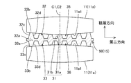
- the second cushioning sheet 90 of the first example includes a base portion 31, a plurality of first elastic protrusions 32, and a plurality of second elastic protrusions 33.
- the second buffer sheet 90 of the first example is different from the first buffer sheet 40 of the first example in that not only the first surface 41a side of the base portion 41 but also a plurality of elastic This corresponds to a configuration including the protrusion 42.
- the base portion 31 is formed in a flat plate shape, and the first surface 31 a at a distance from the target surface 11 a 1 of one battery cell 11 and the other battery cell 11 Has a second surface 31b separated from the target surface 11a1.
- the plurality of first elastic projections 32 are independent of each other, and are formed to project from the first surface 31 a of the base 31.
- the plurality of first elastic projections 32 are formed in a ridge shape extending in a first direction (a direction orthogonal to the second direction).
- the first elastic projection 32 includes a trapezoidal base 32a, a trapezoidal top 32b, an outer trapezoidal oblique side 32c, and an inner trapezoidal oblique side 32d, similarly to the elastic projections 42 of the first example.
- a slit 35 extending in the first direction is formed between adjacent first elastic projections 32.
- the plurality of second elastic projections 33 are independent of each other, and are formed to project from the second surface 31 b of the base 31.
- the plurality of second elastic projections 33 are formed in a ridge shape extending in a first direction (a direction orthogonal to the second direction).
- the second elastic projection 33 includes a trapezoidal base 33a, a trapezoidal top 33b, an outer trapezoidal oblique side 33c, and an inner trapezoidal oblique side 33d, similarly to the elastic projections 42 of the first example.
- a slit 36 extending in the first direction is formed between the adjacent second elastic projections 33.
- the second buffer sheet 90 is sandwiched between the adjacent battery cells 11 and 11.
- the second cushioning sheet 90 includes a first elastic protrusion 32 and a second elastic protrusion 33 on both side surfaces of the base portion 31. Therefore, the second buffer sheet 90 exhibits the same function as the first buffer sheet 40 of the first example with respect to the adjacent battery cells 11 sandwiching the second buffer sheet 90.
- the configuration of the first buffer sheets 50, 60, 70, 80 of the second to fifth examples can be applied to the second buffer sheet 90 of the first example.
Landscapes
- Chemical & Material Sciences (AREA)
- Chemical Kinetics & Catalysis (AREA)
- Electrochemistry (AREA)
- General Chemical & Material Sciences (AREA)
- Engineering & Computer Science (AREA)
- Manufacturing & Machinery (AREA)
- Secondary Cells (AREA)
- Battery Mounting, Suspending (AREA)
Abstract
電池モジュール用緩衝シートは、電池セル(11)の満充電時に対応する所定の弾性突部(42)が最大負荷状態である場合において、所定の弾性突部(42)において、弾性突部(42)の突出方向を弾性基準(C1)とした場合に弾性基準(C1)に対する外側台形斜辺(42c)の傾斜鋭角度を、(φa)と定義する。電池セル(11)の対象面(11a1)のうち所定の弾性突部(42)が当接する部位(P1,P2)において、電池セル(11)の満充電時において、電池セル(11)の積層方向を積層基準(C2)とした場合に積層基準(C2)に対する電池セル(11)の対象面(11a1)の法線の傾斜鋭角度を、θと定義する。そして、「φa ≧ θ」の関係を満たすように設定されている。
Description
本発明は、電池モジュール用緩衝シートに関するものである。
電池モジュールは、自動車等に適用されており、走行距離の延長化のため、電池の高エネルギー密度化が進んできている。電池セルは、高エネルギー密度化によって、充電に伴う発熱によって膨張し、放電に伴って収縮することが知られている。また、充放電の繰り返しにより電池が劣化し、放電時において完全に元の形状まで収縮せず、放電時においても徐々に膨張側にシフトすることも知られている。そこで、複数の電池セルの積層体を、積層体の両端から、一対の拘束部材によって拘束する構造が、特許第5122898号公報、特開2017-212120号公報、特許第6277987号公報、及び特開2006-253149号公報に記載されている。
特許第5122898号公報に記載の電池モジュールにおいては、電池セルと拘束部材との間に、複数個の弾性体を点在して配置することが記載されている。特開2017-212120号公報に記載の電池モジュールにおいては、電池セルの膨張を抑制するために、隣り合う電池セルの間に、低ばね定数凸部および高ばね定数凸部を有するスペーサが配置されている。
特許第6277987号公報に記載の電池モジュールにおいては、電池セルと拘束部材との間に、シート状の弾性部材が配置されている。さらに、当該電池セルは、隣り合う電池セルとの当接部位を、リブ状に形成することにより、隣り合う電池セルの間に冷却空気を流通させている。また、特開2006-253149号公報に記載の電池モジュールにおいては、隣り合う電池セルの間に冷却空気を流通させるために、隣り合う電池セルの間に、複数の突起を有する隔壁が配置されている。
特許第5122898号公報、特開2017-212120号公報、及び特許第6277987号公報に記載の電池モジュールのように、弾性部材を介在させることによって、電池セルの大変位に対しても吸収することができる。また、弾性部材は、電池セルの積層数の変化にも対応が容易であることからも有用である。
ただし、特許第6277987号公報に記載の弾性部材のように、突起を有しない形状に比べて、特許第5122898号公報及び特開2017-212120号公報に記載の弾性部材のように、突起を有する形状の方が、電池セルの変位の吸収力が高くなる。しかしながら、弾性部材を突起形状とする場合には、座屈や倒れが生じるおそれがある。突起状の弾性部材に座屈や倒れが生じると、突起状の弾性部材は、電池セルに対して十分な反力を発揮することができず、結果として電池セルの長寿命化の効果を効果的に発揮することができないおそれがある。
本発明は、電池モジュールに適用され、電池セルの充電時に確実に弾性支持し、電池セルの放電時に確実に反力を付与することができる電池モジュール用緩衝シートを提供することを目的とする。
電池モジュール用緩衝シートは、複数の電池セルの積層体と前記積層体の積層方向の両端から前記積層体を拘束する一対の拘束部材とを備える電池モジュールに適用され、前記電池セルの対象面と前記拘束部材との間、または、隣接する前記電池セルの対象面の間に介在される。
電池モジュール用緩衝シートは、前記電池セルの前記対象面から距離を隔てた第一面を有する板状のベース部と、弾性材料により形成され、前記ベース部の前記第一面から前記電池セルの前記対象面に向かって突出形成され、前記電池セルの前記対象面に直交する断面において複数配列され、配列方向の断面形状が台形形状に形成されており、前記電池セルの充電に伴う湾曲状の膨張時に前記電池セルを弾性支持し、且つ、前記電池セルの放電に伴う収縮時に前記電池セルに対して反力を付与する弾性突部とを備える。
前記弾性突部の前記配列方向の断面形状は、前記電池セルの前記対象面に当接する台形頂辺と、前記台形頂辺と前記ベース部とを接続する辺であって前記電池モジュール用緩衝シートの前記配列方向の外側を向く外側台形斜辺とを備える。前記電池セルの満充電時に対応する所定の前記弾性突部が最大負荷状態である場合において、前記所定の前記弾性突部において、前記弾性突部の突出方向を弾性基準とした場合に前記弾性基準に対する前記外側台形斜辺の傾斜鋭角度を、φaと定義する。前記対象面のうち前記所定の前記弾性突部が当接する部位において、前記電池セルの満充電時において、前記電池セルの積層方向を積層基準とした場合に前記積層基準に対する前記電池セルの前記対象面の法線の傾斜鋭角度を、θと定義する。そして、式(1)の関係を満たすように設定されている。
φa ≧ θ ・・・ (1)
φa ≧ θ ・・・ (1)
上記により、電池セルの対象面のうち所定の弾性突部が当接する部位において、満充電時における電池セルの対象面の法線が、台形形状の弾性突部の内部に存在する状態となる。換言すると、満充電時において、弾性突部が電池セルの対象面から受ける力線が、弾性突部の内部に存在する状態となる。従って、満充電時において、電池セルの対象面が湾曲凸状に膨張した場合に、弾性突部が電池セルの対象面から力を受けたとしても、弾性突部は圧縮されるだけで、座屈や倒れを生じることを防止できる。その結果、電池モジュール用緩衝シートの弾性突部は、電池セルの満充電時に確実に弾性支持し、電池セルの放電時に確実に反力を付与することができる。
(1.電池モジュールの全体構成)
(1-1.第一例の電池モジュール1)
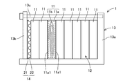
第一例の電池モジュール1について、図1および図2を参照して説明する。図1に示すように、電池モジュール1は、例えば、自動車のバッテリ等として用いられる。電池モジュール1は、複数の電池セル11を積層された積層体12と、拘束部材13と、第一緩衝シート14とを備える。
(1-1.第一例の電池モジュール1)
第一例の電池モジュール1について、図1および図2を参照して説明する。図1に示すように、電池モジュール1は、例えば、自動車のバッテリ等として用いられる。電池モジュール1は、複数の電池セル11を積層された積層体12と、拘束部材13と、第一緩衝シート14とを備える。
積層体12を構成する各電池セル11は、直方体形状の扁平状に形成されている。積層体12は、扁平状の電池セル11を、扁平面方向に直交する方向(扁平法線方向)に積層されている。電池セル11は、電力を充放電可能な二次電池であり、例えば、リチウムイオン二次電池等が好適に用いられる。
電池セル11は、直方体形状の扁平箱形状に形成された筐体11aと、筐体11aの内部に巻回された電極体11bとを備える。筐体11aは、例えばアルミニウム等の金属、または、硬質樹脂等により形成されている。以下において、筐体11aにおいて、扁平面方向に直交する面を対象面11a1と称する。電極体11bは、正極電極と、負極電極と、正極電極と負極電極との間に挟まれたセパレータとを備え、扁平状に巻回されている。
図2に示すように、電極体11bは、充電に伴って発熱することによって、主として扁平法線方向に膨張する。反対に、電極体11bは、放電に伴って収縮する。従って、電極体11bを収容する電池セル11の筐体11aは、充電時には、扁平法線方向に膨張する。特に、筐体11aが直方体形状の扁平箱形状に形成されているため、対象面11a1が湾曲凸状に膨張変形しやすい。特に、電池セル11の満充電時には、筐体11aの対象面11a1の膨張量が最大となる。電池セル11の放電時には、電極体11bの収縮すること伴って、筐体11aの対象面11a1は、理想的には、平面状に復帰する。ただし、電極体11bの劣化によって、徐々に元の形状にまで戻らなくなり、電池性能が低下していく。
拘束部材13は、積層体12を、積層体12の積層方向の両端から拘束する。つまり、拘束部材13は、各電池セル11が充電によって膨張した場合に各電池セル11に対して反力を付与することにより、電池セル11を初期状態(膨張していない状態)に戻すように作用する。
拘束部材13は、第一拘束部材13a、第二拘束部材13b、および、連結部材13cを備える。第一拘束部材13aは、L字状に形成されており、積層体12の台座としての部分と、積層体12の第一端側(図1の右側)の部分(端部拘束部分)とに配置される。詳細には、第一拘束部材13aの端部拘束部分は、積層体12の第一端に位置する電池セル11の対象面11a1に対向するように配置される。さらに、第一拘束部材13aの端部拘束部分における電池セル11側の面は、平面状に形成されている。
第二拘束部材13bは、平板状に形成されており、積層体12の第一端の反対である第二端側(図1の左側)に配置される。詳細には、第二拘束部材13bは、積層体12の第二端に位置する電池セル11の対象面11a1に対向するように配置される。さらに、第二拘束部材13bにおける電池セル11側の面は、平面状に形成されている。
従って、積層体12は、第一拘束部材13aと第二拘束部材13bとによって、積層方向に挟まれる状態となる。連結部材13cは、第一拘束部材13aと第二拘束部材13bとを連結する。拘束部材13を構成する各部材13a,13b,13cは、十分な拘束力を発揮するために、金属が好適に用いられるが、硬質樹脂を適用することも可能である。
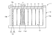
第一緩衝シート14は、積層体12の第二端に位置する電池セル11の対象面11a1と、第二拘束部材13bとの間に介在される。第一緩衝シート14は、弾性体部分を有することにより、電池セル11の膨張および収縮に伴う変形を吸収する。そして、第一緩衝シート14は、図1に示すように、電池セル11の収縮時において、電池セル11を弾性支持する。さらに、第一緩衝シート14は、図2に示すように、電池セル11の充電に伴う膨張時において、電池セル11を弾性支持すると共に、電池セル11の放電に伴う収縮時に電池セルに対して反力を付与する。
特に、積層体12を構成する電池セル11の数が多いほど、電池セル11の膨張および収縮に伴う積層体12の全長の変化は大きくなる。従って、積層体12の全長の変化を確実に吸収するために、弾性体部分を有する第一緩衝シート14が上記機能を好適に発揮する。
第一緩衝シート14は、板状のベース部21と、弾性突部22とを備える。ベース部21の第一面は、積層体12の第二端に位置する電池セル11の対象面11a1から距離を隔てて配置される。ベース部21の第二面は、第二拘束部材13bに当接する。弾性突部22は、弾性材料により形成されており、ベース部21の第一面から面法線方向に突出し、電池セル11の対象面11a1に当接する。そして、弾性突部22は、電池セル11の充電に伴う湾曲凸状の膨張時に、電池セル11を弾性支持する。さらに、弾性突部22は、電池セル11の放電に伴う収縮時に、電池セル11に対して反力を付与する。
(1-2.第二例の電池モジュール2)
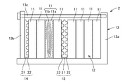
第二例の電池モジュール2について、図3を参照して説明する。電池モジュール2は、複数の電池セル11を積層された積層体12と、拘束部材13と、第一緩衝シート14と、第二緩衝シート15とを備える。第二例の電池モジュール2において、第二緩衝シート15以外の構成は、第一例の電池モジュール1と同一構成であるため、説明を省略する。
第二例の電池モジュール2について、図3を参照して説明する。電池モジュール2は、複数の電池セル11を積層された積層体12と、拘束部材13と、第一緩衝シート14と、第二緩衝シート15とを備える。第二例の電池モジュール2において、第二緩衝シート15以外の構成は、第一例の電池モジュール1と同一構成であるため、説明を省略する。
第二緩衝シート15は、隣接する2つの電池セル11,11の対象面11a1,11a1の間に介在される。第二緩衝シート15は、第一緩衝シート14と同様に、弾性体部分を有することにより、電池セル11の膨張および収縮に伴う変形を吸収する。つまり、第二緩衝シート15は、電池セル11の充電に伴う膨張時において、電池セル11を弾性支持すると共に、電池セル11の放電に伴う収縮時に電池セルに対して反力を付与する。
第二緩衝シート15は、板状のベース部31と、第一弾性突部32と、第二弾性突部33とを備える。ベース部31の第一面は、隣り合う2つの電池セル11,11のうち一方の電池セル11の対象面11a1から距離を隔てて配置される。ベース部31の第二面は、他方の電池セル11の対象面11a1から距離を隔てて配置される。
第一弾性突部32は、弾性材料により形成されており、ベース部31の第一面から面法線方向に突出し、一方の電池セル11の対象面11a1に当接する。そして、第一弾性突部32は、当該一方の電池セル11の充電に伴う湾曲凸状の膨張時に、当該一方の電池セル11を弾性支持する。さらに、第一弾性突部32は、当該一方の電池セル11の放電に伴う収縮時に、当該一方の電池セル11に対して反力を付与する。
第二弾性突部33は、弾性材料により形成されており、ベース部31の第二面から面法線方向に突出し、他方の電池セル11の対象面11a1に当接する。そして、第二弾性突部33は、当該他方の電池セル11の充電に伴う湾曲凸状の膨張時に、当該他方の電池セル11を弾性支持する。さらに、第二弾性突部33は、当該他方の電池セル11の放電に伴う収縮時に、当該他方の電池セル11に対して反力を付与する。
(2.第一例の第一緩衝シート40)
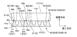
(2-1.第一例の第一緩衝シート40の構成)
第一緩衝シート14の一例としての第一例の第一緩衝シート40について図4および図5を参照して説明する。図4は、第一緩衝シート40の斜視図を示し、図5は、第一緩衝シート40の断面図であって、電池モジュール1,2に適用していない状態、すなわち無負荷状態の図である。
(2-1.第一例の第一緩衝シート40の構成)
第一緩衝シート14の一例としての第一例の第一緩衝シート40について図4および図5を参照して説明する。図4は、第一緩衝シート40の斜視図を示し、図5は、第一緩衝シート40の断面図であって、電池モジュール1,2に適用していない状態、すなわち無負荷状態の図である。
第一例の第一緩衝シート40は、ベース部41と、複数の弾性突部42とを備える。第一緩衝シート40は、ベース部41と弾性突部42とを一体的に形成されており、全体が弾性材料の一つとしてのエラストマーにより形成されている。第一緩衝シート40には、例えば、低温環境下に優れたエラストマーとして、EPDM等が好適に用いられる。
なお、第一緩衝シート40において、ベース部41と弾性突部42とを異なる材質として、両者を接合することも可能である。例えば、ベース部41をアルミニウム等の金属板材とし、弾性突部42をエラストマーにより形成することも可能である。また、ベース部41および弾性突部42に、異なる種類のエラストマーを用いて、2色成形により第一緩衝シート40を形成することも可能である。
ベース部41は、平板状に形成されており、電池セル11の対象面11a1から距離を隔てた第一面41a、および、第二拘束部材13bに当接する第二面41bを有する。ベース部41は、エラストマーにより形成されているため、第一緩衝シート40単体として存在する場合には、可撓性を有する。ただし、第一緩衝シート40が電池モジュール1,2に適用されている状態においては、ベース部41の第二面41bが第二拘束部材13bに当接しているため、ベース部41は、実質的に第二拘束部材13bの面形状に沿った状態で規制される。本実施形態においては、第二拘束部材13bは、平面状に形成されているため、ベース部41は、平板状となる。
複数の弾性突部42は、それぞれ独立しており、ベース部41の第一面41aから突出形成されている。複数の弾性突部42は、第一方向に延びる畝状に形成されている。つまり、複数の弾性突部42は、第一方向に向かって直線状に盛り上げられた部位に相当し、隣り合う弾性突部42の間には、第一方向に延びるスリット43が形成されている。
ここで、第一緩衝シート40について、図4の第一方向に直交し、且つ、電池セル11の対象面11a1(図1に示す)に直交する断面は、図5に示すようになる。従って、図5に示す断面において、複数の弾性突部42は、第一方向に直交する第二方向に、複数配列されていることになる。以下、第二方向を、配列方向と称し、図5に示す断面を、配列方向の断面と称する。
弾性突部42の配列方向の断面形状は、図5に示すように、台形形状に形成されている。本実施形態においては、弾性突部42の当該断面形状は、等脚台形に形成されている。さらに、複数の弾性突部42の当該断面形状は、同一形状に形成されている。ただし、後述するが、複数の弾性突部42の当該断面形状は、異なる形状に形成されるようにしてもよい。弾性突部42は、ベース部41に接続される台形底辺42a、電池セル11の対象面11a1に当接する台形頂辺42b、台形頂辺42bとベース部41(台形底辺42a)とを接続する辺であって第一緩衝シート40の配列方向の外側を向く外側台形斜辺42c、および、台形頂辺42bとベース部41とを接続する辺であって第一緩衝シート40の配列方向の中央側を向く内側台形斜辺42dを備える。
ここで、弾性突部42の突出方向を弾性基準C1とする。そして、弾性突部42が無負荷状態である場合に、当該弾性突部42において、弾性基準C1に対する外側台形斜辺42cの傾斜鋭角度を、φbと定義する。本実施形態においては、全ての弾性突部42における外側台形斜辺42cの傾斜鋭角度φbが、同一とされている。
(2-2.満充電時における電池セル11と第一緩衝シート40の形状)
次に、全ての電池セル11が満充電時における電池セル11と第一緩衝シート40の形状について、図6A、図6B、図6Cを参照して説明する。図6Aは、電池セル11と第一緩衝シート40の両者を示し、図6Bは、図6Aにおける電池セル11のみを示し、図6Cは、図6Aにおける第一緩衝シート40のみを示す。
次に、全ての電池セル11が満充電時における電池セル11と第一緩衝シート40の形状について、図6A、図6B、図6Cを参照して説明する。図6Aは、電池セル11と第一緩衝シート40の両者を示し、図6Bは、図6Aにおける電池セル11のみを示し、図6Cは、図6Aにおける第一緩衝シート40のみを示す。
図6Aに示すように、電池セル11の満充電時においては、電池セル11が最大膨張状態となる。詳細には、電池セル11の対象面11a1は、湾曲凸状に膨張変形する。対象面11a1は、略円弧凸状に膨張変形する。また、積層体12は、複数の電池セル11により構成されている。従って、全ての電池セル11の満充電時においては、第二端に位置する電池セル11の対象面11a1の位置は、放電時に比べて、第二拘束部材13b側にスライドする。
弾性突部42の台形頂辺42bは、電池セル11の対象面11a1に当接し、弾性突部42の台形底辺42aが接続されているベース部41は、第二拘束部材13bによって平面状に拘束されている。そのため、弾性突部42は、圧縮負荷を受ける状態、特に、満充電時には最大の圧縮負荷を受ける状態となる。詳細には、弾性突部42は、積層体12の積層方向に圧縮されると共に、弾性突部42の台形頂辺42bは、電池セル11の対象面11a1の湾曲凸状を転写した湾曲凹状となる。
ただし、弾性突部42は、複数の弾性突部42の配列方向(第二方向)の位置に応じて変形状態が異なる。そこで、以下の説明において、複数の弾性突部42のうち、複数の弾性突部42の配列方向(第二方向)において、外側に位置する弾性突部42を外側弾性突部421とし、中央側に位置する弾性突部42を内側弾性突部422とする。
図6Bに示すように、電池セル11の積層方向を積層基準C2とする。そして、複数の弾性突部42が最大圧縮負荷状態である場合に、電池セル11の対象面11a1のうち弾性突部42が当接する部位Pにおいて、積層基準C2に対する電池セル11の対象面11a1の法線の傾斜鋭角度を、θと定義する。
ここで、電池セル11の傾斜鋭角度θと、無負荷状態における弾性突部42の傾斜鋭角度φbとは、式(1)の関係を有する。つまり、無負荷状態における弾性突部42の傾斜鋭角度φbは、電池セル11の傾斜鋭角度θ以上に設定されている。
φb ≧ θ ・・・ (1)
φb ≧ θ ・・・ (1)
ただし、電池セル11の対象面11a1は、上述したように、湾曲凸状に膨張するため、部位によって傾斜鋭角度θが異なる。そこで、電池セル11の対象面11a1のうち外側弾性突部421が当接する部位P1において、積層基準C2に対する電池セル11の対象面11a1の法線の傾斜鋭角度を、θ1と定義する。電池セル11の対象面11a1のうち内側弾性突部422が当接する部位P2において、積層基準C2に対する電池セル11の対象面11a1の法線の傾斜鋭角度を、θ2と定義する。部位P1の傾斜鋭角度θ1と部位P2の傾斜鋭角度θ2とは、式(2)の関係を有する。
θ1 > θ2 ・・・ (2)
θ1 > θ2 ・・・ (2)
そして、電池セル11の部位P1の傾斜鋭角度θ1と、無負荷状態における弾性突部42の傾斜鋭角度φbとは、式(3)の関係を有する。また、電池セル11の部位P2の傾斜鋭角度θ2と、無負荷状態における弾性突部42の傾斜鋭角度φbとは、式(4)の関係を有する。つまり、無負荷状態における弾性突部42の傾斜鋭角度φbは、部位P1の傾斜鋭角度θ1以上であり、部位P2の傾斜鋭角度θ2以上に設定されている。
φb ≧ θ1 ・・・ (3)
φb ≧ θ2 ・・・ (4)
φb ≧ θ1 ・・・ (3)
φb ≧ θ2 ・・・ (4)
次に、図6Cに示すように、弾性突部42が最大圧縮負荷状態である場合に、当該弾性突部42において、弾性基準C1に対する外側台形斜辺42cの傾斜鋭角度を、φaと定義する。ここで、弾性突部42は、無負荷状態に比べて、圧縮変形している。そのため、弾性突部42において、無負荷状態における外側台形斜辺42cの傾斜鋭角度φbと、最大負荷状態における外側台形斜辺42cの傾斜鋭角度φaとは、式(5)の関係を有する。
φa > φb ・・・ (5)
φa > φb ・・・ (5)
ただし、電池セル11の対象面11a1が湾曲凸状に膨張するため、弾性突部42の部位によって傾斜鋭角度φaが異なる。そこで、外側弾性突部421の傾斜鋭角度を、φa1と定義し、内側弾性突部422の傾斜鋭角度を、φa2と定義する。
そして、最大負荷状態における外側弾性突部421の傾斜鋭角度φa1と、電池セル11の部位P1の傾斜鋭角度θ1とは、式(3)(5)より、式(6)の関係を有する。傾斜鋭角度φa1は、傾斜鋭角度θ1より大きく設定されている。
φa1 > θ1 ・・・ (6)
φa1 > θ1 ・・・ (6)
また、最大負荷状態における内側弾性突部422の傾斜鋭角度φa2と、電池セル11の部位P2の傾斜鋭角度θ2とは、式(4)(5)より、式(7)の関係を有する。傾斜鋭角度φa2は、傾斜鋭角度θ2より大きく設定されている。
φa2 > θ2 ・・・ (7)
φa2 > θ2 ・・・ (7)
式(6)(7)の関係を有するように設定されることより、電池セル11の対象面11a1のうち所定の弾性突部421,422が当接する部位P1,P2において、満充電時における電池セル11の対象面11a1の法線が、台形形状の弾性突部421,422の内部に存在する状態となる。換言すると、満充電時において、弾性突部421,422が電池セル11の対象面11a1から受ける力線が、弾性突部421,422の内部に存在する状態となる。従って、満充電時において、電池セル11の対象面11a1が湾曲凸状に膨張した場合に、弾性突部421,422が電池セル11の対象面11a1から力を受けたとしても、弾性突部421,422は圧縮されるだけで、座屈や倒れを生じることを防止できる。その結果、第一緩衝シート40の弾性突部421,422は、電池セル11の満充電時に確実に弾性支持し、電池セル11の放電時に確実に反力を付与することができる。
さらに、式(6)(7)の関係に加えて、式(3)(4)の関係を有するように設定されることにより、弾性突部421,422が無負荷状態から最大負荷状態に至るまで、確実に、弾性突部421,422が電池セル11の対象面11a1から受ける力線が、弾性突部421,422の内部に存在する状態となる。従って、確実に、弾性突部421,422に座屈や倒れを生じることを防止できる。
さらに、第一緩衝シート40は、スリット43が第一方向に延びるように形成されている。そのため、スリット43が、電池セル11の対象面11a1と第一緩衝シート40との間に、空気を流通させる流路として機能する。従って、第一緩衝シート40がスリット43を有することにより、流通する空気による冷却機能を有することになる。その結果、電池セル11の発熱を抑制し、ひいては膨張を抑制することができる。
(3.第一例の第一緩衝シート40の変形態様)
第一例の第一緩衝シート40において、複数の弾性突部42の当該断面形状は、同一形状に形成した。これに限られず、弾性突部42が無負荷状態である場合において、弾性突部42に関する傾斜鋭角度φbは、対象面11a1の部位P1,P2に応じて異なる角度に設定されるようにしてもよい。
第一例の第一緩衝シート40において、複数の弾性突部42の当該断面形状は、同一形状に形成した。これに限られず、弾性突部42が無負荷状態である場合において、弾性突部42に関する傾斜鋭角度φbは、対象面11a1の部位P1,P2に応じて異なる角度に設定されるようにしてもよい。
弾性突部42が無負荷状態である場合に、部位P1に対応する外側弾性突部421の傾斜鋭角度を、φb1(図5に示す)と定義し、内側弾性突部422の傾斜鋭角度を、φb2(図5に示す)と定義する。そして、外側弾性突部421の傾斜鋭角度φb1と、内側弾性突部422の傾斜鋭角度φb2とは、式(8)の関係を有するように設定される。
φb1 > φb2 ・・・ (8)
φb1 > φb2 ・・・ (8)
つまり、式(2)のように、部位P1の傾斜鋭角度θ1が、部位P2の傾斜鋭角度θ2より大きくなることに対応させて、外側弾性突部421の傾斜鋭角度φb1を内側弾性突部422の傾斜鋭角度φb2より大きくなるように設定されている。これにより、各部位に応じて、適切な傾斜鋭角度φb1,φb2に設定している。
(4.第二例の第一緩衝シート50)
第一緩衝シート14の一例としての第二例の第一緩衝シート50について図7および図5を参照して説明する。図7は、第一緩衝シート50の斜視図を示し、電池モジュール1,2に適用していない状態、すなわち無負荷状態の図である。図5は、図7における凹所53を通る断面形状に相当する。
第一緩衝シート14の一例としての第二例の第一緩衝シート50について図7および図5を参照して説明する。図7は、第一緩衝シート50の斜視図を示し、電池モジュール1,2に適用していない状態、すなわち無負荷状態の図である。図5は、図7における凹所53を通る断面形状に相当する。
第二例の第一緩衝シート50は、ベース部41と、弾性突部52とを備える。弾性突部52は、格子状に形成されており、全体が一体的に接続されている。格子状の弾性突部52の中央には、凹所53が形成されている。つまり、弾性突部52において、電池セル11の対象面11a1と当接する面は、格子状となる。
弾性突部52の凹所53を通る断面形状は、図5に示すようになる。ここで、図5に示す第一緩衝シート50の断面形状は、図7における第一緩衝シート50において、凹所53を通り、且つ、第二方向に平行な方向の断面形状を示す。つまり、弾性突部52は、当該断面において、複数配列されている状態となる。そこで、弾性突部52において、当該断面の方向(第二方向)を、第二配列方向と称する。
また、弾性突部52は、凹所53を通り、且つ、第一方向に平行な方向の断面において、第二方向と同様に、複数配列されている状態となる。そこで、弾性突部52において、当該断面の第一方向を、第一配列方向と称する。つまり、弾性突部52は、第一配列方向において複数配列されると共に、第二配列方向において複数配列される。
そして、弾性突部52の各断面形状は、図5に示すように、台形形状に形成されている。つまり、弾性突部52は、台形底辺42a、台形頂辺42b、外側台形斜辺42c、および、内側台形斜辺42dを備える。各辺42a,42b,42c,42dは、第一例と実質的に同様であるため、説明を省略する。従って、第一緩衝シート50は、第一例と実質的に同様の機能を発揮する。ただし、第二例の第一緩衝シート50においては、弾性突部52が格子状であるため、電池セル11の支持力を大きくすることができる。
(5.第三例の第一緩衝シート60)
第一緩衝シート14の一例としての第三例の第一緩衝シート60について図8および図5を参照して説明する。図8は、第一緩衝シート60の斜視図を示し、電池モジュール1,2に適用していない状態、すなわち無負荷状態の図である。図5は、図8における凹所63を通り、且つ、第二方向に平行な断面形状に相当する。
第一緩衝シート14の一例としての第三例の第一緩衝シート60について図8および図5を参照して説明する。図8は、第一緩衝シート60の斜視図を示し、電池モジュール1,2に適用していない状態、すなわち無負荷状態の図である。図5は、図8における凹所63を通り、且つ、第二方向に平行な断面形状に相当する。
第三例の第一緩衝シート60は、ベース部41と、弾性突部62とを備える。弾性突部62は、第二例の第一緩衝シート50の弾性突部52のように格子状に形成されており、全体が一体的に接続されている。そして、格子状の弾性突部62の中央には、凹所63が形成されている。さらに、弾性突部62は、第一方向において、隣り合う凹所63,63同士を連通する空気連通溝64を有する。つまり、空気連通溝64の部分は、電池セル11の対象面11a1との間に隙間を有する状態となる。空気連通溝64は、弾性突部62における第二方向に延びる部分の全てに形成されている。
従って、空気連通溝64は、第一例の第一緩衝シート40のスリット43と同様の機能を発揮する。すなわち、第一緩衝シート60が空気連通溝64を有することにより、空気連通溝64を流通する空気による冷却機能を有することになる。その結果、電池セル11の発熱を抑制し、ひいては膨張を抑制することができる。
さらに、第三例の第一緩衝シート60は、弾性突部62が、高さの違いを有しつつも、格子状に形成されている。従って、第三例の第一緩衝シート60は、第一例の第一緩衝シート40に比べて、電池セル11の支持力を大きくすることができる。
(6.第四例の第一緩衝シート70)
第一緩衝シート14の一例としての第四例の第一緩衝シート70について図9および図5を参照して説明する。図9は、第一緩衝シート70の斜視図を示し、電池モジュール1,2に適用していない状態、すなわち無負荷状態の図である。図5は、図9における凹所73を通り、且つ、第二方向に平行な断面形状に相当する。
第一緩衝シート14の一例としての第四例の第一緩衝シート70について図9および図5を参照して説明する。図9は、第一緩衝シート70の斜視図を示し、電池モジュール1,2に適用していない状態、すなわち無負荷状態の図である。図5は、図9における凹所73を通り、且つ、第二方向に平行な断面形状に相当する。
第四例の第一緩衝シート70は、ベース部41と、弾性突部72とを備える。弾性突部72は、第二例の第一緩衝シート50の弾性突部52と同様に格子状に形成されており、全体が一体的に接続されている。そして、格子状の弾性突部72の中央には、凹所73が形成されている。さらに、弾性突部72は、第一方向において、隣り合う凹所73,73同士を連通する空気連通孔74を有する。空気連通孔74は、弾性突部72における第二方向に延びる部分の全てに形成されている。
従って、空気連通孔74は、第一例の第一緩衝シート40のスリット43と同様の機能を発揮する。すなわち、第一緩衝シート70が空気連通孔74を有することにより、空気連通孔74を流通する空気による冷却機能を有することになる。その結果、電池セル11の発熱を抑制し、ひいては膨張を抑制することができる。
また、空気連通孔74は、弾性突部72における電池セル11の対象面11a1との当接面から離れた位置に形成されている。従って、弾性突部72において、電池セル11の対象面11a1と当接する面は、格子状となる。従って、第四例の第一緩衝シート70は、第一例の第一緩衝シート40に比べて、電池セル11の支持力を大きくすることができる。
(7.第五例の第一緩衝シート80)
第一緩衝シート14の一例としての第五例の第一緩衝シート80について図10および図5を参照して説明する。図10は、第一緩衝シート80の斜視図を示し、電池モジュール1,2に適用していない状態、すなわち無負荷状態の図である。図5は、図10における弾性突部82を通る断面形状に相当する。
第一緩衝シート14の一例としての第五例の第一緩衝シート80について図10および図5を参照して説明する。図10は、第一緩衝シート80の斜視図を示し、電池モジュール1,2に適用していない状態、すなわち無負荷状態の図である。図5は、図10における弾性突部82を通る断面形状に相当する。
第五例の第一緩衝シート80は、ベース部41と、複数の弾性突部82とを備える。複数の弾性突部82は、それぞれ独立しており、ベース部41の第一面41aから突出形成されている。特に、複数の弾性突部82は、第一面41aから電池セル11の対象面11a1に向かって、柱状に立設されている。図10においては、各弾性突部82は、円錐台形状に形成されている。ただし、各弾性突部82は、円錐台形状に限られず、四角錐台形状、その他の多角形錐台形状とすることもできる。
従って、複数の弾性突部82は、第一方向(第一配列方向)に複数個独立して配列されると共に、第二方向(第二配列方向)に複数個独立して配列される。また、図10においては、複数の弾性突部82は、直交する第一方向と第二方向のそれぞれに配列する例を示す。つまり、近接する4個の弾性突部82が、長方形の頂点となるように配置されている。この他に、第一方向に代えて、第一方向および第二方向に対して角度を有する方向に複数個独立して配列するようにしてもよい。つまり、近接する4個の弾性突部82が、平行四辺形の頂点となるように配置してもよい。すなわち、第一方向と第二方向とは、交差する方向であればよい。
そして、弾性突部82を通る断面形状は、図5に示すように、台形形状に形成されている。つまり、弾性突部82は、台形底辺42a、台形頂辺42b、外側台形斜辺42c、および、内側台形斜辺42dを備える。各辺42a,42b,42c,42dは、第一例と実質的に同様であるため、説明を省略する。従って、第一緩衝シート80は、第一例と実質的に同様の機能を発揮する。
(8.第一例の第二緩衝シート90)
第二緩衝シート15の一例としての第一例の第二緩衝シート90について図11を参照して説明する。第一例の第二緩衝シート90は、ベース部31と、複数の第一弾性突部32と、複数の第二弾性突部33とを備える。ここで、第一例の第二緩衝シート90は、第一例の第一緩衝シート40に対して、ベース部41の第一面41a側に加えて第二面41b側にも、複数の弾性突部42を備える構成に相当する。
第二緩衝シート15の一例としての第一例の第二緩衝シート90について図11を参照して説明する。第一例の第二緩衝シート90は、ベース部31と、複数の第一弾性突部32と、複数の第二弾性突部33とを備える。ここで、第一例の第二緩衝シート90は、第一例の第一緩衝シート40に対して、ベース部41の第一面41a側に加えて第二面41b側にも、複数の弾性突部42を備える構成に相当する。
第一例の第二緩衝シート90において、ベース部31は、平板状に形成されており、一方の電池セル11の対象面11a1から距離を隔てた第一面31a、および、他方の電池セル11の対象面11a1から距離を隔てた第二面31bを有する。
複数の第一弾性突部32は、それぞれ独立しており、ベース部31の第一面31aから突出形成されている。複数の第一弾性突部32は、第一方向(第二方向に直交する方向)に延びる畝状に形成されている。第一弾性突部32は、第一例の弾性突部42と同様に、台形底辺32a、台形頂辺32b、外側台形斜辺32c、および、内側台形斜辺32dを備える。隣り合う第一弾性突部32の間には、第一方向に延びるスリット35が形成されている。
複数の第二弾性突部33は、それぞれ独立しており、ベース部31の第二面31bから突出形成されている。複数の第二弾性突部33は、第一方向(第二方向に直交する方向)に延びる畝状に形成されている。第二弾性突部33は、第一例の弾性突部42と同様に、台形底辺33a、台形頂辺33b、外側台形斜辺33c、および、内側台形斜辺33dを備える。隣り合う第二弾性突部33の間には、第一方向に延びるスリット36が形成されている。
第二緩衝シート90は、隣り合う電池セル11,11の間に挟まれている。そして、第二緩衝シート90は、ベース部31の両側面のそれぞれに、第一弾性突部32および第二弾性突部33を備えている。従って、第二緩衝シート90は、当該第二緩衝シート90を挟む隣り合う電池セル11,11に対して、第一例の第一緩衝シート40と同様に機能を発揮する。なお、第一例の第二緩衝シート90は、第二例から第五例の第一緩衝シート50,60,70,80の構成を適用することもできる。
1,2:電池モジュール、 11:電池セル、 11a:筐体、 11a1:対象面、 11b:電極体、 12:電池セルの積層体、 13:拘束部材、 13a:第一拘束部材、 13b:第二拘束部材、 13c:連結部材、 14:第一緩衝シート、 15:第二緩衝シート、 21:ベース部、 22:弾性突部、 31:ベース部、 31a:第一面、 31b:第二面、 32:第一弾性突部、 32a:台形底辺、 32b:台形頂辺、 32c:外側台形斜辺、 32d:内側台形斜辺、 33:第二弾性突部、 33a:台形底辺、 33b:台形頂辺、 33c:外側台形斜辺、 33d:内側台形斜辺、 35,36:スリット、 40:第一緩衝シート、 41:ベース部、 41a:第一面、 41b:第二面、 42:弾性突部、 42a:台形底辺、 42b:台形頂辺、 42c:外側台形斜辺、 42d:内側台形斜辺、 43:スリット、 50:第一緩衝シート、 52:弾性突部、 53:凹所、 60:第一緩衝シート、 62:弾性突部、 63:凹所、 64:空気連通溝、 70:第一緩衝シート、 72:弾性突部、 73:凹所、 74:空気連通孔、 80:第一緩衝シート、 82:弾性突部、 90:第二緩衝シート、 421:外側弾性突部、 422:内側弾性突部、 C1:弾性基準、 C2:積層基準、 P,P1,P2:電池セルの対象面の部位、 θ,θ1,θ2:電池セルの対象面の法線の傾斜鋭角度、 φa,φa1,φa2:最大負荷状態における弾性突部の外側台形斜辺の傾斜鋭角度、 φb,φb1,φb2:無負荷状態における弾性突部の外側台形斜辺の傾斜鋭角度
Claims (9)
- 複数の電池セルの積層体と前記積層体の積層方向の両端から前記積層体を拘束する拘束部材とを備える電池モジュールに適用され、
前記電池セルの対象面と前記拘束部材との間、または、隣接する前記電池セルの対象面の間に介在される、電池モジュール用緩衝シートであって、
前記電池セルの前記対象面から距離を隔てた第一面を有する板状のベース部と、
弾性材料により形成され、前記ベース部の前記第一面から前記電池セルの前記対象面に向かって突出形成され、前記電池セルの前記対象面に直交する断面において複数配列され、配列方向の断面形状が台形形状に形成されており、前記電池セルの充電に伴う湾曲状の膨張時に前記電池セルを弾性支持し、且つ、前記電池セルの放電に伴う収縮時に前記電池セルに対して反力を付与する弾性突部と、
を備え、
前記弾性突部の前記配列方向の断面形状は、
前記電池セルの前記対象面に当接する台形頂辺と、
前記台形頂辺と前記ベース部とを接続する辺であって前記電池モジュール用緩衝シートの前記配列方向の外側を向く外側台形斜辺と、
を備え、
前記電池セルの満充電時に対応する所定の前記弾性突部が最大負荷状態である場合において、前記所定の前記弾性突部において、前記弾性突部の突出方向を弾性基準とした場合に前記弾性基準に対する前記外側台形斜辺の傾斜鋭角度を、φaと定義し、
前記対象面のうち前記所定の前記弾性突部が当接する部位において、前記電池セルの満充電時において、前記電池セルの積層方向を積層基準とした場合に前記積層基準に対する前記電池セルの前記対象面の法線の傾斜鋭角度を、θと定義し、
式(1)の関係を満たすように設定されている、電池モジュール用緩衝シート。
φa ≧ θ ・・・ (1) - 前記所定の前記弾性突部が無負荷状態である場合において、前記弾性基準に対する前記外側台形斜辺の傾斜鋭角度を、φbとし、
式(2)の関係を満たすように設定されている、請求項1に記載の電池モジュール用緩衝シート。
φb ≧ θ ・・・ (2) - 前記電池セルは、電極巻回体と、前記電極巻回体を収容し前記対象面を有する筐体と、を備え、
前記対象面は、充電時に湾曲凸状に膨張変形する、請求項1または2に記載の電池モジュール用緩衝シート。 - 前記所定の前記弾性突部が無負荷状態である場合において、前記弾性突部に関する前記傾斜鋭角度φbは、前記対象面の位置に応じて異なる角度に設定されている、請求項1-3の何れか一項に記載の電池モジュール用緩衝シート。
- 前記弾性突部は、前記配列方向に直交する方向に延びる畝状に形成され、
隣り合う前記弾性突部の間には、スリットが形成される、請求項1-4の何れか一項に記載の電池モジュール用緩衝シート。 - 前記弾性突部は、格子状に形成され、
前記格子状の前記弾性突部の中央には、凹所が形成され、
前記弾性突部の前記配列方向の前記断面形状は、前記凹所を通る断面形状である、請求項1-4の何れか一項に記載の電池モジュール用緩衝シート。 - 前記弾性突部は、隣り合う前記凹所同士を連通する空気連通溝を有する、請求項6に記載の電池モジュール用緩衝シート。
- 前記弾性突部は、隣り合う前記凹所同士を連通する空気連通孔を有する、請求項6に記載の電池モジュール用緩衝シート。
- 前記弾性突部は、前記ベース部の前記第一面から前記電池セルの前記対象面に向かって柱状に立設され、
前記弾性突部は、第一の前記配列方向に複数個独立して配列されると共に、前記第一の前記配列方向に交差する第二の前記配列方向に複数個独立して配列される、請求項1-4の何れか一項に記載の電池モジュール用緩衝シート。
Applications Claiming Priority (2)
| Application Number | Priority Date | Filing Date | Title |
|---|---|---|---|
| JP2018121487A JP7063744B2 (ja) | 2018-06-27 | 2018-06-27 | 電池モジュール用緩衝シート |
| JP2018-121487 | 2018-06-27 |
Publications (1)
| Publication Number | Publication Date |
|---|---|
| WO2020004039A1 true WO2020004039A1 (ja) | 2020-01-02 |
Family
ID=68987082
Family Applications (1)
| Application Number | Title | Priority Date | Filing Date |
|---|---|---|---|
| PCT/JP2019/023306 WO2020004039A1 (ja) | 2018-06-27 | 2019-06-12 | 電池モジュール用緩衝シート |
Country Status (2)
| Country | Link |
|---|---|
| JP (1) | JP7063744B2 (ja) |
| WO (1) | WO2020004039A1 (ja) |
Cited By (5)
| Publication number | Priority date | Publication date | Assignee | Title |
|---|---|---|---|---|
| CN112234294A (zh) * | 2020-11-09 | 2021-01-15 | 湖南宝特瑞能新能源有限责任公司 | 基于多角度减震的锂电池安装稳定结构 |
| CN114824605A (zh) * | 2021-01-27 | 2022-07-29 | 丰田自动车株式会社 | 载荷施加装置以及蓄电装置 |
| CN115244773A (zh) * | 2020-08-05 | 2022-10-25 | 株式会社Lg新能源 | 具有能够吸收电池膨胀的结构的电池模块、以及包括电池模块的电池组和的车辆 |
| WO2023001464A1 (fr) * | 2021-07-22 | 2023-01-26 | Renault S.A.S. | Cellule électrochimique de stockage d'énergie électrique |
| DE102022130024A1 (de) | 2022-11-14 | 2024-05-16 | Dr. Ing. H.C. F. Porsche Aktiengesellschaft | Batteriemodul mit einem Kühlmodul sowie Kühlmodul |
Families Citing this family (6)
| Publication number | Priority date | Publication date | Assignee | Title |
|---|---|---|---|---|
| KR20220052111A (ko) * | 2020-10-20 | 2022-04-27 | 주식회사 엘지에너지솔루션 | 배터리 모듈, 이를 포함하는 배터리 팩 및 자동차 |
| KR20220053251A (ko) * | 2020-10-22 | 2022-04-29 | 주식회사 엘지에너지솔루션 | 전지 모듈 및 이를 포함하는 전지 팩 |
| KR102629554B1 (ko) | 2021-06-18 | 2024-01-26 | 진양오토모티브 (주) | 세이프티 패드 그리고, 이를 구비하는 배터리셀 및 배터리모듈 |
| JP7475550B2 (ja) | 2021-08-17 | 2024-04-26 | Nok株式会社 | バッテリー用緩衝材 |
| CN114824617A (zh) * | 2022-05-18 | 2022-07-29 | 中创新航科技股份有限公司 | 一种电池包、电池包的组装方法及电池簇 |
| JP7323233B1 (ja) * | 2022-12-16 | 2023-08-08 | 東和化学株式会社 | シート状緩衝構造体及びその製造方法 |
Citations (4)
| Publication number | Priority date | Publication date | Assignee | Title |
|---|---|---|---|---|
| JPH09199094A (ja) * | 1996-01-17 | 1997-07-31 | Matsushita Electric Ind Co Ltd | 蓄電池用電槽および蓄電池 |
| JP2006049054A (ja) * | 2004-08-04 | 2006-02-16 | Toyota Motor Corp | シート材型電池、シート材型電池を組み合わせた組電池及びシート材型電池の製造方法 |
| JP2006253149A (ja) * | 2005-03-11 | 2006-09-21 | Samsung Sdi Co Ltd | 二次電池モジュール |
| JP2018006058A (ja) * | 2016-06-29 | 2018-01-11 | トヨタ自動車株式会社 | 電池モジュール |
Family Cites Families (4)
| Publication number | Priority date | Publication date | Assignee | Title |
|---|---|---|---|---|
| JP5504554B2 (ja) * | 2006-11-06 | 2014-05-28 | ソニー株式会社 | 電池パックの製造方法及び電池パック |
| JP6201301B2 (ja) * | 2012-11-19 | 2017-09-27 | 株式会社Gsユアサ | 電池モジュール及び中間部材 |
| JP2014238924A (ja) * | 2013-06-06 | 2014-12-18 | トヨタ自動車株式会社 | 電池パック |
| JP6500554B2 (ja) * | 2015-03-27 | 2019-04-17 | 株式会社豊田自動織機 | 電池モジュール |
-
2018
- 2018-06-27 JP JP2018121487A patent/JP7063744B2/ja active Active
-
2019
- 2019-06-12 WO PCT/JP2019/023306 patent/WO2020004039A1/ja active Application Filing
Patent Citations (4)
| Publication number | Priority date | Publication date | Assignee | Title |
|---|---|---|---|---|
| JPH09199094A (ja) * | 1996-01-17 | 1997-07-31 | Matsushita Electric Ind Co Ltd | 蓄電池用電槽および蓄電池 |
| JP2006049054A (ja) * | 2004-08-04 | 2006-02-16 | Toyota Motor Corp | シート材型電池、シート材型電池を組み合わせた組電池及びシート材型電池の製造方法 |
| JP2006253149A (ja) * | 2005-03-11 | 2006-09-21 | Samsung Sdi Co Ltd | 二次電池モジュール |
| JP2018006058A (ja) * | 2016-06-29 | 2018-01-11 | トヨタ自動車株式会社 | 電池モジュール |
Cited By (8)
| Publication number | Priority date | Publication date | Assignee | Title |
|---|---|---|---|---|
| CN115244773A (zh) * | 2020-08-05 | 2022-10-25 | 株式会社Lg新能源 | 具有能够吸收电池膨胀的结构的电池模块、以及包括电池模块的电池组和的车辆 |
| EP4142029A4 (en) * | 2020-08-05 | 2024-03-27 | Lg Energy Solution Ltd | BATTERY MODULE HAVING A STRUCTURE CAPABLE OF ABSORBING CELL SWELLING, AND BATTERY PACK AND VEHICLE COMPRISING SAME |
| CN112234294A (zh) * | 2020-11-09 | 2021-01-15 | 湖南宝特瑞能新能源有限责任公司 | 基于多角度减震的锂电池安装稳定结构 |
| CN114824605A (zh) * | 2021-01-27 | 2022-07-29 | 丰田自动车株式会社 | 载荷施加装置以及蓄电装置 |
| CN114824605B (zh) * | 2021-01-27 | 2024-05-03 | 丰田自动车株式会社 | 载荷施加装置以及蓄电装置 |
| WO2023001464A1 (fr) * | 2021-07-22 | 2023-01-26 | Renault S.A.S. | Cellule électrochimique de stockage d'énergie électrique |
| FR3125633A1 (fr) * | 2021-07-22 | 2023-01-27 | Renault S.A.S. | Cellule électrochimique de stockage d’énergie électrique |
| DE102022130024A1 (de) | 2022-11-14 | 2024-05-16 | Dr. Ing. H.C. F. Porsche Aktiengesellschaft | Batteriemodul mit einem Kühlmodul sowie Kühlmodul |
Also Published As
| Publication number | Publication date |
|---|---|
| JP7063744B2 (ja) | 2022-05-09 |
| JP2020004556A (ja) | 2020-01-09 |
Similar Documents
| Publication | Publication Date | Title |
|---|---|---|
| WO2020004039A1 (ja) | 電池モジュール用緩衝シート | |
| JP7174923B2 (ja) | 蓄電装置 | |
| JP6319332B2 (ja) | 組電池 | |
| US8852789B2 (en) | Battery module having battery cell holder | |
| EP2416431A2 (en) | Battery module having flexibility in design structure of module and medium to large sized battery pack including the same | |
| JP6571577B2 (ja) | 組電池 | |
| JP2014501022A (ja) | 強化された安全性を有する電池モジュール | |
| CN108140769B (zh) | 弹性板及包括弹性板的电池单元组件 | |
| WO2014024409A1 (ja) | 組電池 | |
| US20090061294A1 (en) | Battery case and battery pack using the same | |
| JP2017195018A (ja) | 電池パック | |
| JP7208273B2 (ja) | 電池モジュール | |
| CN111180622B (zh) | 电池组 | |
| JP2018018629A (ja) | 電池モジュール | |
| CN113924687A (zh) | 缓冲构件、蓄电模块以及缓冲构件的制造方法 | |
| EP3373360B1 (en) | Battery module | |
| WO2020235279A1 (ja) | バスバープレート | |
| JP6589543B2 (ja) | 電池モジュール | |
| US20170271628A1 (en) | Secondary battery | |
| US20220285773A1 (en) | Buffer member and power storage module | |
| JP6031388B2 (ja) | 組電池 | |
| JP7309588B2 (ja) | 組電池 | |
| US20230170573A1 (en) | Battery module | |
| US11289764B2 (en) | Battery pack | |
| US20220384838A1 (en) | Battery module for a traction battery of an electric vehicle |
Legal Events
| Date | Code | Title | Description |
|---|---|---|---|
| 121 | Ep: the epo has been informed by wipo that ep was designated in this application |
Ref document number: 19824512 Country of ref document: EP Kind code of ref document: A1 |
|
| NENP | Non-entry into the national phase |
Ref country code: DE |
|
| 122 | Ep: pct application non-entry in european phase |
Ref document number: 19824512 Country of ref document: EP Kind code of ref document: A1 |