WO2020003834A1 - Position detection device - Google Patents
Position detection device Download PDFInfo
- Publication number
- WO2020003834A1 WO2020003834A1 PCT/JP2019/020721 JP2019020721W WO2020003834A1 WO 2020003834 A1 WO2020003834 A1 WO 2020003834A1 JP 2019020721 W JP2019020721 W JP 2019020721W WO 2020003834 A1 WO2020003834 A1 WO 2020003834A1
- Authority
- WO
- WIPO (PCT)
- Prior art keywords
- phase value
- value
- corrected
- phase
- calculation
- Prior art date
Links
Images


Classifications
-
- G—PHYSICS
- G01—MEASURING; TESTING
- G01D—MEASURING NOT SPECIALLY ADAPTED FOR A SPECIFIC VARIABLE; ARRANGEMENTS FOR MEASURING TWO OR MORE VARIABLES NOT COVERED IN A SINGLE OTHER SUBCLASS; TARIFF METERING APPARATUS; MEASURING OR TESTING NOT OTHERWISE PROVIDED FOR
- G01D5/00—Mechanical means for transferring the output of a sensing member; Means for converting the output of a sensing member to another variable where the form or nature of the sensing member does not constrain the means for converting; Transducers not specially adapted for a specific variable
- G01D5/12—Mechanical means for transferring the output of a sensing member; Means for converting the output of a sensing member to another variable where the form or nature of the sensing member does not constrain the means for converting; Transducers not specially adapted for a specific variable using electric or magnetic means
- G01D5/244—Mechanical means for transferring the output of a sensing member; Means for converting the output of a sensing member to another variable where the form or nature of the sensing member does not constrain the means for converting; Transducers not specially adapted for a specific variable using electric or magnetic means influencing characteristics of pulses or pulse trains; generating pulses or pulse trains
Definitions
- the present invention relates to a position detecting device.
- an encoder for detecting the position of the motor there is known an encoder that outputs a sinusoidal A-phase signal and a B-phase signal that differ in phase by approximately 90 °.
- the A and B phase signals output from such an encoder usually include an error (all or part of an offset error, an amplitude error, and a phase error).
- the position of the motor can be accurately obtained from the A and B phase signals including the error.
- each coefficient of an elliptic equation approximating the A and B phase signals is obtained from a plurality of combinations of the instantaneous values of the A and B phase signals. For this reason, the above-described technology has a problem that a complicated operation is required and that real-time performance is poor (response to a time change of an error is poor).
- the present invention has been made in view of the above situation, and is a position detecting device that performs error correction to detect a position of a position detection target of an encoder.
- An object is to provide a good position detection device.
- a position detection device includes: an acquisition unit that repeatedly acquires an A-phase value and a B-phase value that are instantaneous values of each signal from an A-phase signal and a B-phase signal from an encoder; Each time the A-phase value and the B-phase value are obtained, the corrected A-phase value and the corrected B-phase value from which the Lissajous waveform is closer to a perfect circle are obtained from the obtained A-phase value and the B-phase value.
- a correction unit that calculates the corrected A-phase value using a first calculation expression that is a linear expression of the A-phase value, and calculates a second calculation expression that is a linear expression of the B-phase value.
- a correction unit that calculates the corrected B-phase value by using the correction unit, and calculates each coefficient value of the first calculation expression and the second calculation expression used in the current calculation by the correction unit in the previous calculation by the correction unit.
- Each used coefficient value, the corrected A-phase value previously calculated by the correction unit, and the correction From the B-phase value and the coefficient calculation unit that calculates from the A-phase value and the B-phase value corrected in the current calculation, and from the corrected A-phase value and the corrected B-phase value calculated by the correction unit,
- a position calculation unit for calculating a position of the position detection target of the encoder.
- the positions detecting device functions as a position detecting device having a smaller calculation load and good real-time performance than the existing device.
- the coefficient calculation unit various calculation units having different specific calculation procedures can be employed.
- ““ the square value of the corrected A-phase value + the square value of the corrected B-phase value ⁇ 1 ” Calculates the coefficient values of the first and second arithmetic expressions used in the next arithmetic operation by the correction unit by the steepest descent method so that the square value of becomes the minimum value.
- a position detecting device which performs error correction to detect a position of an object to be detected by an encoder, and has a smaller calculation load and a better real-time property than an existing device. Can be.
- FIG. 1 is an explanatory diagram of a configuration and a use form of a position detection device according to a first embodiment of the present invention.
- FIG. 2 is an explanatory diagram of a configuration of a motor control device including a position detection device.
- FIG. 3 is an explanatory diagram of the error correction performance of the position detection device.
- FIG. 4 is an explanatory diagram of a configuration and a use form of a position detection device according to a second embodiment of the present invention.
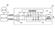
- FIG. 1 is an explanatory diagram of a configuration and a usage pattern of a position detecting device 10 according to a first embodiment of the present invention
- FIG. 2 is an explanatory diagram of a configuration of a motor control device 20 including the position detecting device 10. .
- the position detection device 10 is a device that calculates the position ⁇ of the motor 30 based on the A-phase signal and the B-phase signal including an error from the encoder 31. Further, as shown in FIG. 2, the position detecting device 10 is a device realized as one function of the control unit 23 in the motor control device 20 for controlling the motor 30.
- the motor drive circuit 22 in the motor control device 20 is an inverter circuit that supplies a drive current to the motor 30 under the control of the control unit 23.
- the control unit 23 is a unit configured of a processor such as a microcontroller, a CPU, and the like, and its peripheral elements, and controls the motor 30 (motor drive circuit 22) using the position ⁇ output from the position detection device 10.
- the control unit 23 controls the motor 30 according to a command input from a host device 35 such as a PLC.
- the position detection device 10 includes two A / D converters 11a and 11b, a correction unit 12, a coefficient calculation unit 13, and a position calculation unit 14.
- the A / D converter 11a is a device for digitizing the A-phase signal.
- the A / D converter 11b is a device for digitizing a B-phase signal.
- the A / D converters 11a and 11b simultaneously sample an input signal at a predetermined cycle and output a sampling result (that is, an instantaneous value of each signal).
- a sampling result that is, an instantaneous value of each signal.
- the instantaneous value of the A-phase signal output from the A / D converter 11a and the instantaneous value of the B-phase signal output from the A / D converter 11b are expressed as x and y, respectively.
- the correction unit 12 is a unit that performs error correction on x and y by the following calculation every time x and y are input.
- corrected x and corrected y x and corrected y after the error correction by the correction unit 12 (x and y with hat symbols in the above formulas (1) and (2)) will be referred to as corrected x and corrected y.
- the coefficient calculating unit 13 calculates each of the coefficient values of the equations (1) and (2) used in the current calculation by the correcting unit 12 as x and y for which the error is to be corrected, and Is a unit that calculates from each coefficient value used in the calculation of (i) and the corrected x and the corrected y previously calculated by the correction unit 12. More specifically, the coefficient calculation unit 13 is a unit that calculates each coefficient value used in the current calculation by the correction unit 12 using the following equation.
- a n, b n, c n, d n, f n is the coefficient values used in the n-th operation by the correcting unit 12. Further, a n + 1 , b n + 1 , c n + 1 , d n + 1 , and f n + 1 are coefficient values used in n + 1 operations by the correction unit 12, and ⁇ is the stability of the search for the best coefficient value by the above recurrence formula. It is a value (> 0) determined in advance in consideration of the performance and convergence.
- the position calculator 14 is a unit that calculates the position ⁇ defined by the following equation (9).
- the instantaneous values x and y of the A-phase signal and the B-phase signal of the encoder 31 can be expressed as cos ⁇ and sin ⁇ . Therefore, the instantaneous values x and y when the offset error, the amplitude error and the phase error are included can be expressed by the following equations (10) and (11).
- Cos ⁇ is a value to be obtained (corrected x)
- the above equation (1) expresses the coefficient and constant term of x in the equation (12) as a and b, respectively. Therefore, if appropriate a and b values are used, the corrected x can be calculated from x by the above equation (1).
- equation (14) is obtained.
- the corrected y is the value to be determined (corrected y), and the above equation (2) expresses the coefficient of y, the constant term, and the coefficient of x in equation (14) as c, d, and f, respectively. . Therefore, by using appropriate c, d, and f values, the corrected y can be calculated from x and y by the above equation (2).
- the position detection device 10 uses the following evaluation function Q.
- the evaluation function Q which is a square value of “square value of x after correction + square value of y after correction ⁇ 1”, takes the minimum value 0 when each coefficient value is an optimum value.
- the coefficient calculation unit 13 is changed to the above-described equations (3) to (8). It is configured to perform the operation of the content specified by
- the correction unit 12 sets the x, y as shown in the upper part of FIG. 3 (that is, the x, y in which the Lissajous waveform does not have a perfect circular shape). Is input, the correction unit 12 outputs the corrected x and the corrected y in which the Lissajous waveform becomes a perfect circle as shown in the lower part of FIG. Therefore, according to the position detection device 10, it is possible to prevent the accuracy of the calculation result of the position ⁇ from deteriorating due to errors included in the A-phase signal and the B-phase signal from the encoder 31.
- the position detection device 10 is a device that has a smaller computational load and better real-time performance than an existing device, and is a device that can be realized (manufactured) without using a high-performance CPU, MPU, or the like. Can be said.
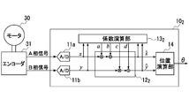
- Figure 4 shows a second implementation and usage of the position detecting device 10 2 according to the embodiment of the present invention.
- Figure 4 shows a second implementation and usage of the position detecting device 10 2 according to the embodiment of the present invention.
- parts different from the position detecting device 10 illustrating the position configuration and function of the detection device 10 2 according to the present embodiment.
- the position detecting device 10 2 is almost no A-phase signal and the B-phase signal phase error has been developed to be inputted. 4 and As is apparent from the comparison between FIG. 1, the position detecting device 10 2, the correction unit 12 of the position detecting device 10 (FIG. 1), the coefficient calculator 13, respectively, the correction unit 12 2, the coefficient calculation It has become a substituted device part 13 2.
- Correcting unit 12 2 is a unit that performs the following operations.
- Coefficient calculator 13. 2 is a unit obtained by modifying the coefficient calculator 13 so as not to perform the calculation of f values.
- the above equation (21) can be used instead of the above equation (2).
- the equations (3) to (6) are equations that can be used as they are for calculating the optimum values of the coefficients of the equations (20) and (21). Accordingly, the correction unit 12 2 having the above functions, according to the position detecting device 10 2 having a coefficient calculator 13 2, can be satisfactorily corrected offset errors and amplitude errors of the A-phase signal and the B-phase signal from the encoder 31 .
- the position detection device (10, 10 2 ) can be variously deformed. For example, when the A-phase signal has almost no offset error, b may be set to “0”, and when the B-phase signal has almost no offset error, d may be set to “0”. Similarly, when there is almost no amplitude error in the A-phase signal and / or the B-phase signal, a and / or c may be set to “1”.
- the position detection target of the encoder 31 may not be the motor 30, and the position detection device may be a device in a device (such as a PLC) that requires ⁇ other than the motor control device 20 or a device that requires ⁇ . It is a matter of course that it may be realized as a device that is used by being connected.
- a correction unit (12) for calculating the post-A-phase value and the corrected B-phase value wherein the correction unit (12) calculates the post-correction A-phase value using a first calculation expression that is a linear expression of the A-phase value;
- the coefficient values of the first calculation expression and the second calculation expression used in the current calculation by the correction unit (12) are calculated by using the respective coefficient values used in the previous calculation by the correction unit (12).
Abstract
This position detection device for subjecting a signal from an encoder to error correction and detecting the position of a part of the encoder to have the position thereof detected comprises a correction unit for correcting A and B phase signals from the encoder using first-order equations for each signal and a coefficient calculation unit for calculating coefficients for the first-order equations for each signal from, for example, previous signal correction coefficients. This position detection device has less computational load than conventional devices and low delay.
Description
本発明は、位置検出装置に関する。
The present invention relates to a position detecting device.
モータの位置を検出するためのエンコーダとして、略90°位相が異なる、正弦波状のA相信号及びB相信号を出力するエンコーダが知られている。そのようなエンコーダから出力されるA、B相信号には、通常、誤差(オフセット誤差,振幅誤差及び位相誤差の全て又は一部)が含まれる。
As an encoder for detecting the position of the motor, there is known an encoder that outputs a sinusoidal A-phase signal and a B-phase signal that differ in phase by approximately 90 °. The A and B phase signals output from such an encoder usually include an error (all or part of an offset error, an amplitude error, and a phase error).
そして、誤差が含まれるA、B相信号からでは、モータの位置を正確に演算することができない。そのため、A、B相信号に含まれるオフセット誤差,振幅誤差及び位相誤差を特定し、特定結果に基づき、A、B相信号を補正した上で、モータの位置を求める技術(例えば、特許文献1)が開発されている。
Then, the position of the motor cannot be accurately calculated from the A and B phase signals including the error. Therefore, an offset error, an amplitude error, and a phase error included in the A and B phase signals are specified, and the A and B phase signals are corrected based on the specified result, and then the position of the motor is determined (for example, Patent Document 1). ) Has been developed.
上記技術によれば、誤差を含むA、B相信号からモータの位置を正確に求めることが可能となる。ただし、上記技術は、各誤差を特定するために、A、B相信号の瞬時値の複数の組み合わせからA、B相信号を近似する楕円の方程式の各係数を求めるものとなっている。そのため、上記技術には、複雑な演算が必要とされる、リアルタイム性が悪い(誤差の時間変化への応答性が悪い)、といった問題があった。
According to the above technique, the position of the motor can be accurately obtained from the A and B phase signals including the error. However, in the above technique, in order to specify each error, each coefficient of an elliptic equation approximating the A and B phase signals is obtained from a plurality of combinations of the instantaneous values of the A and B phase signals. For this reason, the above-described technology has a problem that a complicated operation is required and that real-time performance is poor (response to a time change of an error is poor).
本発明は、上記現状に鑑みなされたものであり、誤差補正を行ってエンコーダの位置検出対象の位置を検出する位置検出装置であって、既存の装置よりも、演算負荷が少なく、リアルタイム性も良い位置検出装置を提供することを目的とする。
The present invention has been made in view of the above situation, and is a position detecting device that performs error correction to detect a position of a position detection target of an encoder. An object is to provide a good position detection device.
本発明の一観点に係る位置検出装置は、エンコーダからのA相信号及びB相信号から、各信号の瞬時値であるA相値及びB相値を繰り返し取得する取得部と、前記取得部により前記A相値及び前記B相値が取得される度に、取得された前記A相値及び前記B相値から、リサージュ波形の形状がより真円に近づく補正後A相値及び補正後B相値を演算する補正部であって、前記A相値の一次式である第1演算式を用いて前記補正後A相値を演算し、前記B相値の一次式である第2演算式を用いて補正後B相値を演算する補正部と、前記補正部による今回の演算で使用される前記第1演算式及び前記第2演算式の各係数値を、前記補正部による前回の演算で使用された各係数値と前記補正部により前回演算された前記補正後A相値及び前記補正後B相値と今回の演算で補正される前記A相値及び前記B相値から演算する係数演算部と、前記補正部により演算された前記補正後A相値及び前記補正後B相値から、前記エンコーダの位置検出対象の位置を演算する位置演算部と、を備える。
A position detection device according to one aspect of the present invention includes: an acquisition unit that repeatedly acquires an A-phase value and a B-phase value that are instantaneous values of each signal from an A-phase signal and a B-phase signal from an encoder; Each time the A-phase value and the B-phase value are obtained, the corrected A-phase value and the corrected B-phase value from which the Lissajous waveform is closer to a perfect circle are obtained from the obtained A-phase value and the B-phase value. A correction unit that calculates the corrected A-phase value using a first calculation expression that is a linear expression of the A-phase value, and calculates a second calculation expression that is a linear expression of the B-phase value. A correction unit that calculates the corrected B-phase value by using the correction unit, and calculates each coefficient value of the first calculation expression and the second calculation expression used in the current calculation by the correction unit in the previous calculation by the correction unit. Each used coefficient value, the corrected A-phase value previously calculated by the correction unit, and the correction From the B-phase value and the coefficient calculation unit that calculates from the A-phase value and the B-phase value corrected in the current calculation, and from the corrected A-phase value and the corrected B-phase value calculated by the correction unit, A position calculation unit for calculating a position of the position detection target of the encoder.
この位置検出装置の補正部及び係数演算部が行う演算は、上記定義から明らかなように、極めて簡単なものである。また、補正部及び係数演算部のいずれが行う演算も、複数組のA相値及びB相値を必要としないものとなっている。従って、本発明の上記観点に係る位置検出装置は、既存の装置よりも、演算負荷が少なく、リアルタイム性も良い位置検出装置として機能する。
The operations performed by the correction unit and the coefficient operation unit of this position detection device are extremely simple, as is clear from the above definition. Further, the calculations performed by either the correction unit or the coefficient calculation unit do not require a plurality of sets of A-phase values and B-phase values. Therefore, the position detecting device according to the above aspect of the present invention functions as a position detecting device having a smaller calculation load and good real-time performance than the existing device.
なお、第1演算式、第2演算式としては、通常、定数項がある(つまり、定数項が“0”ではない)式が使用される。ただし、オフセット誤差が殆どない場合には、各演算式として、定数項がない(定数項が“0”の)一次式を採用しても良い。また、第2演算式として、前記B相値及び前記A相値のそれぞれについての一次式を採用しておけば、位相誤差も補正可能な位置検出装置を得ることができる。
Note that, as the first and second arithmetic expressions, an expression having a constant term (that is, the constant term is not “0”) is usually used. However, when there is almost no offset error, a linear equation having no constant term (the constant term is “0”) may be used as each arithmetic expression. In addition, if a linear expression for each of the B-phase value and the A-phase value is adopted as the second arithmetic expression, it is possible to obtain a position detection device capable of correcting a phase error.
また、係数演算部としては、具体的な演算手順が異なる様々なものを採用することができるが、『“前記補正後A相値の二乗値+前記補正後B相値の二乗値-1”の二乗値が、最小値となるように、最急降下法により、前記補正部による次回の演算で使用される前記第1演算式及び前記第2演算式の各係数値を演算する』係数演算部を採用しておけば、演算負荷が特に少ない位置検出装置を得ることができる。
Further, as the coefficient calculation unit, various calculation units having different specific calculation procedures can be employed. However, ““ the square value of the corrected A-phase value + the square value of the corrected B-phase value−1 ” Calculates the coefficient values of the first and second arithmetic expressions used in the next arithmetic operation by the correction unit by the steepest descent method so that the square value of becomes the minimum value. " Is adopted, it is possible to obtain a position detection device with a particularly small calculation load.
本発明によれば、誤差補正を行ってエンコーダの位置検出対象の位置を検出する位置検出装置であって、既存の装置よりも、演算負荷が少なく、リアルタイム性も良い位置検出装置を提供することができる。
According to the present invention, there is provided a position detecting device which performs error correction to detect a position of an object to be detected by an encoder, and has a smaller calculation load and a better real-time property than an existing device. Can be.
以下、図面に基づいて、本発明の実施の形態を説明する。
Hereinafter, embodiments of the present invention will be described with reference to the drawings.
《第1実施形態》
図1に、本発明の第1実施形態に係る位置検出装置10の構成及び使用形態の説明図を示し、図2に、位置検出装置10を備えたモータ制御装置20の構成の説明図を示す。 << 1st Embodiment >>
FIG. 1 is an explanatory diagram of a configuration and a usage pattern of aposition detecting device 10 according to a first embodiment of the present invention, and FIG. 2 is an explanatory diagram of a configuration of a motor control device 20 including the position detecting device 10. .
図1に、本発明の第1実施形態に係る位置検出装置10の構成及び使用形態の説明図を示し、図2に、位置検出装置10を備えたモータ制御装置20の構成の説明図を示す。 << 1st Embodiment >>
FIG. 1 is an explanatory diagram of a configuration and a usage pattern of a
図1に示してあるように、本実施形態に係る位置検出装置10は、エンコーダ31からの、誤差を含むA相信号及びB相信号に基づき、モータ30の位置θを演算する装置である。また、位置検出装置10は、図2に示してあるように、モータ30を制御するためのモータ制御装置20内の制御部23の一機能として実現された装置となっている。なお、このモータ制御装置20内のモータ駆動回路22は、制御部23の制御下、モータ30に駆動電流を供給するインバータ回路である。制御部23は、マイクロコントローラ、CPU等のプロセッサとその周辺素子から構成された、位置検出装置10が出力する位置θを利用してモータ30(モータ駆動回路22)を制御するユニットである。この制御部23は、PLC等の上位装置35から入力される指令に従ってモータ30を制御する。
As shown in FIG. 1, the position detection device 10 according to the present embodiment is a device that calculates the position θ of the motor 30 based on the A-phase signal and the B-phase signal including an error from the encoder 31. Further, as shown in FIG. 2, the position detecting device 10 is a device realized as one function of the control unit 23 in the motor control device 20 for controlling the motor 30. The motor drive circuit 22 in the motor control device 20 is an inverter circuit that supplies a drive current to the motor 30 under the control of the control unit 23. The control unit 23 is a unit configured of a processor such as a microcontroller, a CPU, and the like, and its peripheral elements, and controls the motor 30 (motor drive circuit 22) using the position θ output from the position detection device 10. The control unit 23 controls the motor 30 according to a command input from a host device 35 such as a PLC.
図1に示してあるように、位置検出装置10は、2つのA/Dコンバータ11a及び11bと、補正部12と、係数演算部13と、位置演算部14とを備える。
As shown in FIG. 1, the position detection device 10 includes two A / D converters 11a and 11b, a correction unit 12, a coefficient calculation unit 13, and a position calculation unit 14.
A/Dコンバータ11aは、A相信号をデジタル化するためのデバイスである。A/Dコンバータ11bは、B相信号をデジタル化するためのデバイスである。A/Dコンバータ11a及び11bは、所定周期で同時に入力信号のサンプリングを行って、サンプリング結果(すなわち、各信号の瞬時値)を出力する。以下、A/Dコンバータ11aが出力するA相信号の瞬時値、A/Dコンバータ11bが出力するB相信号の瞬時値のことを、それぞれ、x、yと表記する。
The A / D converter 11a is a device for digitizing the A-phase signal. The A / D converter 11b is a device for digitizing a B-phase signal. The A / D converters 11a and 11b simultaneously sample an input signal at a predetermined cycle and output a sampling result (that is, an instantaneous value of each signal). Hereinafter, the instantaneous value of the A-phase signal output from the A / D converter 11a and the instantaneous value of the B-phase signal output from the A / D converter 11b are expressed as x and y, respectively.
補正部12は、x及びyが入力される度に、以下の演算により、x、yに対して誤差補正を施すユニットである。
The correction unit 12 is a unit that performs error correction on x and y by the following calculation every time x and y are input.

以下、補正部12による誤差補正後のx、y(上記(1)式、(2)式におけるハット記号付きのx、y)のことを、補正後x、補正後yと表記する。
Hereinafter, x and y after the error correction by the correction unit 12 (x and y with hat symbols in the above formulas (1) and (2)) will be referred to as corrected x and corrected y.
係数演算部13は、補正部12による今回の演算で使用される上記(1)式及び(2)式の各係数値を、誤差補正対象となっているx及びyと、補正部12による前回の演算で使用された各係数値と、補正部12により前回演算された補正後x及び補正後yとから算出するユニットである。より具体的には、係数演算部13は、以下の式により、補正部12による今回の演算で使用される各係数値を算出するユニットとなっている。
The coefficient calculating unit 13 calculates each of the coefficient values of the equations (1) and (2) used in the current calculation by the correcting unit 12 as x and y for which the error is to be corrected, and Is a unit that calculates from each coefficient value used in the calculation of (i) and the corrected x and the corrected y previously calculated by the correction unit 12. More specifically, the coefficient calculation unit 13 is a unit that calculates each coefficient value used in the current calculation by the correction unit 12 using the following equation.
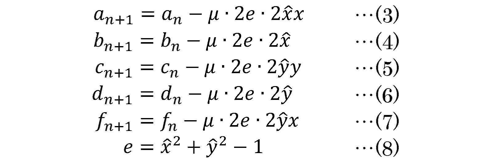
上記式において、an、bn、cn、dn、fnは、補正部12によるn回目の演算で使用された係数値である。また、an+1、bn+1、cn+1、dn+1、fn+1は、補正部12によるn+1回の演算で使用される係数値であり、μは、上記漸化式による最良係数値の探索の安定性及び収束性を考慮して予め定められる値(>0)である。
In the above formula, a n, b n, c n, d n, f n is the coefficient values used in the n-th operation by the correcting unit 12. Further, a n + 1 , b n + 1 , c n + 1 , d n + 1 , and f n + 1 are coefficient values used in n + 1 operations by the correction unit 12, and μ is the stability of the search for the best coefficient value by the above recurrence formula. It is a value (> 0) determined in advance in consideration of the performance and convergence.
なお、係数演算部13は、補正部12による1回目の演算時には、各係数値として、予め設定されている値(例えば、a1=1、c1=1、b1=d1=f1=0)を出力する。
In addition, at the time of the first calculation by the correction unit 12, the coefficient calculation unit 13 sets, as each coefficient value, a preset value (for example, a 1 = 1, c 1 = 1, b 1 = d 1 = f 1). = 0).
位置演算部14は、以下の(9)式で定義される位置θを演算するユニットである。
The position calculator 14 is a unit that calculates the position θ defined by the following equation (9).

ここで、本実施形態に係る位置検出装置10に、上記構成を採用している理由を説明しておくことにする。
Here, the reason why the above configuration is employed in the position detection device 10 according to the present embodiment will be described.
誤差が含まれない場合の、エンコーダ31のA相信号、B相信号の瞬時値x、yは、cosθ、sinθと表記することができる。従って、オフセット誤差,振幅誤差及び位相誤差を含む場合の瞬時値x、yを、以下の(10)式、(11)式で表せることになる。
瞬時 When no error is included, the instantaneous values x and y of the A-phase signal and the B-phase signal of the encoder 31 can be expressed as cos θ and sin θ. Therefore, the instantaneous values x and y when the offset error, the amplitude error and the phase error are included can be expressed by the following equations (10) and (11).

(10)式をcosθについての式に変形すると、以下の(12)式が得られる。
変 形 By transforming equation (10) into an equation for cos θ, the following equation (12) is obtained.

cosθが求めたい値(補正後x)であり、上記(1)式は、この(12)式におけるxの係数、定数項を、それぞれ、a、bと表記したものである。従って、適切なa、b値を用いれば、上記(1)式により、xから、補正後xを算出することができる。
Cosθ is a value to be obtained (corrected x), and the above equation (1) expresses the coefficient and constant term of x in the equation (12) as a and b, respectively. Therefore, if appropriate a and b values are used, the corrected x can be calculated from x by the above equation (1).
また、(11)式を、以下の(13)式(三角関数の加法定理)及び上記(12)式を用いて、sinθについての式に変形すると、以下の(14)式が得られる。
変 形 Also, by transforming equation (11) into an equation for sinθ using equation (13) (addition theorem of trigonometric function) and equation (12), equation (14) is obtained.

sinθが求めたい値(補正後y)であり、上記(2)式は、(14)式におけるyの係数、定数項、xの係数を、それぞれ、c、d、fと表記したものである。従って、適切なc、d、f値を用いれば、上記(2)式によって、x及びyから、補正後yを算出することができる。
is the value to be determined (corrected y), and the above equation (2) expresses the coefficient of y, the constant term, and the coefficient of x in equation (14) as c, d, and f, respectively. . Therefore, by using appropriate c, d, and f values, the corrected y can be calculated from x and y by the above equation (2).
そして、適切な各係数値の求め方には様々なものがあるが、各係数値が最適値である場合に最小値(極小値)を取る、各種偏微分値を求めやすい評価関数Qを定めて、最急降下法により各係数値が求められるようにしておけば、演算負荷を低減できる。
There are various methods for obtaining appropriate coefficient values, and an evaluation function Q for easily obtaining various partial differential values, which takes a minimum value (minimum value) when each coefficient value is an optimum value, is determined. The calculation load can be reduced by determining each coefficient value by the steepest descent method.
そのように考えに基づき、想到されたのが、係数演算部13の上記演算である。
具体的には、本実施形態に係る位置検出装置10は、以下の評価関数Qが用いられたものとなっている。 Based on such an idea, the above-described calculation of thecoefficient calculation unit 13 has been conceived.
Specifically, theposition detection device 10 according to the present embodiment uses the following evaluation function Q.
具体的には、本実施形態に係る位置検出装置10は、以下の評価関数Qが用いられたものとなっている。 Based on such an idea, the above-described calculation of the
Specifically, the

誤差補正が適切に行われている場合、“補正後xの二乗値+補正後yの二乗値”は、“1”となる。従って、“補正後xの二乗値+補正後yの二乗値-1”の二乗値である上記評価関数Qは、各係数値が最適値である場合に最小値0をとる。また、最急降下法により各係数値を算出する場合、以下の演算(つまり、偏微分値を必要とする演算)が行われることになる。
If the error correction is properly performed, “square value of x after correction + square value of y after correction” is “1”. Therefore, the evaluation function Q, which is a square value of “square value of x after correction + square value of y after correction−1”, takes the minimum value 0 when each coefficient value is an optimum value. When calculating each coefficient value by the steepest descent method, the following calculation (that is, a calculation requiring a partial differential value) is performed.
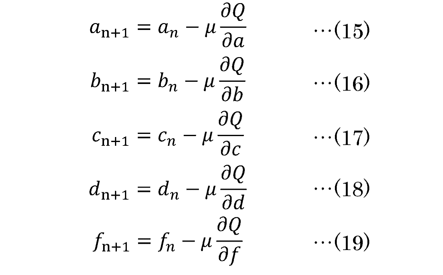
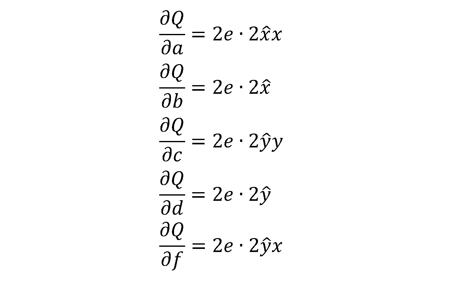
上記評価関数Qは、以下の各式から明らかなように、各偏微分値が極めて簡単に算出できるものとなっている。
評 価 As is clear from the following equations, each partial differential value of the evaluation function Q can be calculated very easily.
このように、評価関数Qを、『“補正後xの二乗値+補正後yの二乗値-1”の二乗値』とすれば、各偏微分値が簡単に演算できる。そして、その結果として、各係数値も簡単に演算できることになる。そのため、評価関数Qとして、『“補正後xの二乗値+補正後yの二乗値-1”の二乗値』を採用した上で、係数演算部13を、上記(3)~(8)式で規定される内容の演算を行うように構成しているのである。
Thus, if the evaluation function Q is “the square value of“ squared value of x after correction + square value of y after correction−1 ””, each partial differential value can be easily calculated. As a result, each coefficient value can be easily calculated. Therefore, after adopting “square value of“ square value of x after correction + square value of y after correction−1 ”” as the evaluation function Q, the coefficient calculation unit 13 is changed to the above-described equations (3) to (8). It is configured to perform the operation of the content specified by
以上、説明した構成を有する本実施形態に係る位置検出装置10では、補正部12に、図3の上段に示したようなx、y(すなわち、リサージュ波形が真円形状とならないx、y)が入力されても、補正部12からは、図3の下段に示したように、リサージュ波形が真円形状となる補正後x及び補正後yが出力される。従って、位置検出装置10によれば、エンコーダ31からのA相信号及びB相信号に含まれる誤差に因り位置θの演算結果の精度が劣化することを防止できる。
In the position detection device 10 according to the present embodiment having the above-described configuration, the correction unit 12 sets the x, y as shown in the upper part of FIG. 3 (that is, the x, y in which the Lissajous waveform does not have a perfect circular shape). Is input, the correction unit 12 outputs the corrected x and the corrected y in which the Lissajous waveform becomes a perfect circle as shown in the lower part of FIG. Therefore, according to the position detection device 10, it is possible to prevent the accuracy of the calculation result of the position θ from deteriorating due to errors included in the A-phase signal and the B-phase signal from the encoder 31.
また、位置検出装置10の補正部12及び係数演算部13が行う演算は、極めて簡単な、複数組のx、yを必要としないものとなっている。従って、位置検出装置10は、既存の装置よりも、演算負荷が少なく、リアルタイム性も良い装置であると共に、高機能なCPU、MPU等を用いることなく実現(製造)可能な装置となっていると言うことができる。
The calculations performed by the correction unit 12 and the coefficient calculation unit 13 of the position detection device 10 are extremely simple and do not require a plurality of sets of x and y. Therefore, the position detection device 10 is a device that has a smaller computational load and better real-time performance than an existing device, and is a device that can be realized (manufactured) without using a high-performance CPU, MPU, or the like. Can be said.
《第2実施形態》
図4に、本発明の第2実施形態に係る位置検出装置102の構成及び使用形態を示す。以下、この図を用いて、位置検出装置10と異なっている部分を中心に、本実施形態に係る位置検出装置102の構成及び機能を説明する。 << 2nd Embodiment >>
Figure 4 shows a second implementation and usage of theposition detecting device 10 2 according to the embodiment of the present invention. Hereinafter, with reference to this figure, mainly to parts different from the position detecting device 10, illustrating the position configuration and function of the detection device 10 2 according to the present embodiment.
図4に、本発明の第2実施形態に係る位置検出装置102の構成及び使用形態を示す。以下、この図を用いて、位置検出装置10と異なっている部分を中心に、本実施形態に係る位置検出装置102の構成及び機能を説明する。 << 2nd Embodiment >>
Figure 4 shows a second implementation and usage of the
本実施形態に係る位置検出装置102は、位相誤差が殆どないA相信号及びB相信号が入力されることを想定して開発したものである。図4と図1とを比較すれば明らかなように、位置検出装置102は、位置検出装置10(図1)の補正部12、係数演算部13を、それぞれ、補正部122、係数演算部132に置換した装置となっている。
The position detecting device 10 2 according to the present embodiment is almost no A-phase signal and the B-phase signal phase error has been developed to be inputted. 4 and As is apparent from the comparison between FIG. 1, the position detecting device 10 2, the correction unit 12 of the position detecting device 10 (FIG. 1), the coefficient calculator 13, respectively, the correction unit 12 2, the coefficient calculation It has become a substituted device part 13 2.
補正部122は、以下の演算を行うユニットである。
Correcting unit 12 2 is a unit that performs the following operations.

係数演算部132は、f値の演算を行わないように係数演算部13を変形したユニットである。
Coefficient calculator 13. 2 is a unit obtained by modifying the coefficient calculator 13 so as not to perform the calculation of f values.
すなわち、位相誤差が殆どないA相信号及びB相信号が入力される場合、上記(2)式の代わりに、上記(21)式を用いることができる。そして、上記した(3)~(6)式は、(20)式及び(21)式の各係数の最適値の算出に、そのまま使用できる式である。従って、上記機能を有する補正部122、係数演算部132を備えた位置検出装置102によれば、エンコーダ31からのA相信号及びB相信号のオフセット誤差及び振幅誤差を良好に補正できる。
That is, when an A-phase signal and a B-phase signal having almost no phase error are input, the above equation (21) can be used instead of the above equation (2). The equations (3) to (6) are equations that can be used as they are for calculating the optimum values of the coefficients of the equations (20) and (21). Accordingly, the correction unit 12 2 having the above functions, according to the position detecting device 10 2 having a coefficient calculator 13 2, can be satisfactorily corrected offset errors and amplitude errors of the A-phase signal and the B-phase signal from the encoder 31 .
《変形形態》
上記した各実施形態に係る位置検出装置(10、102)は、各種の変形が可能なものである。例えば、A相信号にオフセット誤差が殆どない場合には、bを“0”としておいても良く、B相信号にオフセット誤差が殆どない場合には、dを“0”としておいても良い。同様に、A相信号及び/又はB相信号に振幅誤差が殆どない場合には、a及び/又はcを“1”としておいても良い。 《Modified form》
The position detection device (10, 10 2 ) according to each of the embodiments described above can be variously deformed. For example, when the A-phase signal has almost no offset error, b may be set to “0”, and when the B-phase signal has almost no offset error, d may be set to “0”. Similarly, when there is almost no amplitude error in the A-phase signal and / or the B-phase signal, a and / or c may be set to “1”.
エンコーダ31の位置検出対象がモータ30ではなくても良いことや、位置検出装置を、モータ制御装置20以外の、θを必要とする装置(PLC等)内の装置や、θを必要とする装置と接続されて使用される装置として実現しても良いことなどは当然のことである。
The position detection target of the encoder 31 may not be the motor 30, and the position detection device may be a device in a device (such as a PLC) that requires θ other than the motor control device 20 or a device that requires θ. It is a matter of course that it may be realized as a device that is used by being connected.
《付記》
1. エンコーダ(31)からのA相信号及びB相信号から、各信号の瞬時値であるA相値及びB相値を繰り返し取得する取得部(11a、11b)と、
前記取得部(11a、11b)により前記A相値及び前記B相値が取得される度に、取得された前記A相値及び前記B相値から、リサージュ波形の形状がより真円に近づく補正後A相値及び補正後B相値を演算する補正部(12)であって、前記A相値の一次式である第1演算式を用いて前記補正後A相値を演算し、前記B相値の一次式である第2演算式を用いて補正後B相値を演算する補正部(12)と、
前記補正部(12)による今回の演算で使用される前記第1演算式及び前記第2演算式の各係数値を、前記補正部(12)による前回の演算で使用された各係数値と前記補正部(12)により前回演算された前記補正後A相値及び前記補正後B相値と今回の演算で補正される前記A相値及び前記B相値から演算する係数演算部(13)と、
前記補正部(12)により演算された前記補正後A相値及び前記補正後B相値から、前記エンコーダの位置検出対象の位置を演算する位置演算部(14)と、
を備えることを特徴とする位置検出装置(10)。 《Note》
1. An acquisition unit (11a, 11b) for repeatedly acquiring an A-phase value and a B-phase value that are instantaneous values of each signal from the A-phase signal and the B-phase signal from the encoder (31);
Each time the acquisition unit (11a, 11b) acquires the A-phase value and the B-phase value, a correction is made from the acquired A-phase value and the B-phase value so that the shape of the Lissajous waveform becomes closer to a perfect circle. A correction unit (12) for calculating the post-A-phase value and the corrected B-phase value, wherein the correction unit (12) calculates the post-correction A-phase value using a first calculation expression that is a linear expression of the A-phase value; A correction unit (12) that calculates a corrected B-phase value using a second calculation expression that is a linear expression of a phase value;
The coefficient values of the first calculation expression and the second calculation expression used in the current calculation by the correction unit (12) are calculated by using the respective coefficient values used in the previous calculation by the correction unit (12). A coefficient calculator (13) for calculating from the corrected A-phase value and the corrected B-phase value previously calculated by the correction unit (12) and the A-phase value and the B-phase value corrected in the current calculation; ,
A position calculation unit (14) that calculates a position of a position detection target of the encoder from the corrected A-phase value and the corrected B-phase value calculated by the correction unit (12);
A position detection device (10), comprising:
10、102 位置検出装置
11a、11b A/Dコンバータ
12、122 補正部
13、132 係数演算部
14 位置演算部
20 モータ制御装置
22 モータ駆動回路
23 制御部
30 モータ
31 エンコーダ
35 上位装置 10, 10 2 Position detecting device 11a, 11b A / D converter 12, 12 2 correcting unit 13, 13 2 coefficient calculating unit 14 Position calculating unit 20 Motor control device 22 Motor drive circuit 23 Control unit 30 Motor 31 Encoder 35 Host device
11a、11b A/Dコンバータ
12、122 補正部
13、132 係数演算部
14 位置演算部
20 モータ制御装置
22 モータ駆動回路
23 制御部
30 モータ
31 エンコーダ
35 上位装置 10, 10 2
Claims (3)
- エンコーダからのA相信号及びB相信号から、各信号の瞬時値であるA相値及びB相値を繰り返し取得する取得部と、
前記取得部により前記A相値及び前記B相値が取得される度に、取得された前記A相値及び前記B相値から、リサージュ波形の形状がより真円に近づく補正後A相値及び補正後B相値を演算する補正部であって、前記A相値の一次式である第1演算式を用いて前記補正後A相値を演算し、前記B相値の一次式である第2演算式を用いて補正後B相値を演算する補正部と、
前記補正部による今回の演算で使用される前記第1演算式及び前記第2演算式の各係数値を、前記補正部による前回の演算で使用された各係数値と前記補正部により前回演算された前記補正後A相値及び前記補正後B相値と今回の演算で補正される前記A相値及び前記B相値から演算する係数演算部と、
前記補正部により演算された前記補正後A相値及び前記補正後B相値から、前記エンコーダの位置検出対象の位置を演算する位置演算部と、
を備えることを特徴とする位置検出装置。 An acquisition unit that repeatedly acquires an A-phase value and a B-phase value that are instantaneous values of each signal from the A-phase signal and the B-phase signal from the encoder;
Each time the A-phase value and the B-phase value are acquired by the acquisition unit, the corrected A-phase value and the Lissajous waveform shape become closer to a perfect circle from the acquired A-phase value and the B-phase value. A correction unit that calculates a corrected B-phase value, wherein the correction unit calculates the corrected A-phase value using a first calculation expression that is a linear expression of the A-phase value, and calculates a first expression that is a linear expression of the B-phase value. A correction unit that calculates a corrected B-phase value using two arithmetic expressions;
The coefficient values of the first calculation expression and the second calculation expression used in the current calculation by the correction unit are calculated by using the respective coefficient values used in the previous calculation by the correction unit and the previous calculation by the correction unit. A coefficient calculator for calculating from the corrected A-phase value and the corrected B-phase value and the A-phase value and the B-phase value corrected in the current calculation;
From the corrected A-phase value and the corrected B-phase value calculated by the correction unit, a position calculation unit that calculates the position of the position detection target of the encoder,
A position detecting device comprising: - 前記補正部により用いられる前記第2演算式が、前記B相値及び前記A相値のそれぞれについての一次式である、
を備えることを特徴とする請求項1に記載の位置検出装置。 The second arithmetic expression used by the correction unit is a linear expression for each of the B-phase value and the A-phase value.
The position detecting device according to claim 1, further comprising: - 前記係数演算部は、“前記補正後A相値の二乗値+前記補正後B相値の二乗値-1”の二乗値が、最小値となるように、最急降下法により、前記補正部による次回の演算で使用される前記第1演算式及び前記第2演算式の各係数値を演算する、
ことを特徴とする請求項1又は2に記載の位置検出装置。 The coefficient calculation unit performs the steepest descent method so that the square value of “the square value of the corrected A-phase value + the square value of the corrected B-phase value−1” becomes the minimum value. Calculating each coefficient value of the first operation expression and the second operation expression used in the next operation;
The position detecting device according to claim 1 or 2, wherein:
Applications Claiming Priority (2)
| Application Number | Priority Date | Filing Date | Title |
|---|---|---|---|
| JP2018120734A JP2020003254A (en) | 2018-06-26 | 2018-06-26 | Position detector |
| JP2018-120734 | 2018-06-26 |
Publications (1)
| Publication Number | Publication Date |
|---|---|
| WO2020003834A1 true WO2020003834A1 (en) | 2020-01-02 |
Family
ID=68986196
Family Applications (1)
| Application Number | Title | Priority Date | Filing Date |
|---|---|---|---|
| PCT/JP2019/020721 WO2020003834A1 (en) | 2018-06-26 | 2019-05-24 | Position detection device |
Country Status (2)
| Country | Link |
|---|---|
| JP (1) | JP2020003254A (en) |
| WO (1) | WO2020003834A1 (en) |
Citations (6)
| Publication number | Priority date | Publication date | Assignee | Title |
|---|---|---|---|---|
| JPH06119454A (en) * | 1992-10-08 | 1994-04-28 | Babcock Hitachi Kk | Method and device for detecting abnormality |
| JPH1185728A (en) * | 1997-09-10 | 1999-03-30 | Hitachi Ltd | Minimal/minimum value searching method |
| JP2003254784A (en) * | 2002-02-28 | 2003-09-10 | Mitsutoyo Corp | Method and device for calibrating displacement |
| JP2004219333A (en) * | 2003-01-16 | 2004-08-05 | Matsushita Electric Ind Co Ltd | Encoder output signal correcting device |
| US20100050731A1 (en) * | 2008-09-02 | 2010-03-04 | Infineon Technologies Ag | Angle measurement system |
| JP2014025871A (en) * | 2012-07-30 | 2014-02-06 | Mitsutoyo Corp | Encoder output signal correction apparatus |
-
2018
- 2018-06-26 JP JP2018120734A patent/JP2020003254A/en active Pending
-
2019
- 2019-05-24 WO PCT/JP2019/020721 patent/WO2020003834A1/en active Application Filing
Patent Citations (6)
| Publication number | Priority date | Publication date | Assignee | Title |
|---|---|---|---|---|
| JPH06119454A (en) * | 1992-10-08 | 1994-04-28 | Babcock Hitachi Kk | Method and device for detecting abnormality |
| JPH1185728A (en) * | 1997-09-10 | 1999-03-30 | Hitachi Ltd | Minimal/minimum value searching method |
| JP2003254784A (en) * | 2002-02-28 | 2003-09-10 | Mitsutoyo Corp | Method and device for calibrating displacement |
| JP2004219333A (en) * | 2003-01-16 | 2004-08-05 | Matsushita Electric Ind Co Ltd | Encoder output signal correcting device |
| US20100050731A1 (en) * | 2008-09-02 | 2010-03-04 | Infineon Technologies Ag | Angle measurement system |
| JP2014025871A (en) * | 2012-07-30 | 2014-02-06 | Mitsutoyo Corp | Encoder output signal correction apparatus |
Also Published As
| Publication number | Publication date |
|---|---|
| JP2020003254A (en) | 2020-01-09 |
Similar Documents
| Publication | Publication Date | Title |
|---|---|---|
| TWI413780B (en) | The phase correction circuit of the encoder signal | |
| KR101664567B1 (en) | Apparatus and Method for Compensating Position Information Error of Resolver | |
| JP2016527520A5 (en) | ||
| US8775117B2 (en) | Encoder, servo unit, and method including calculating position data | |
| JP2008002904A (en) | Device and program for calculating amplitude of output signal of encoder | |
| JP2014025871A (en) | Encoder output signal correction apparatus | |
| JP7391341B2 (en) | Electrical angle acquisition system, electrical angle acquisition method, and electrical angle acquisition program | |
| JP4515120B2 (en) | Resolver digital angle conversion apparatus and method, and program | |
| JP4508103B2 (en) | Position detection method | |
| WO2020003834A1 (en) | Position detection device | |
| JP2009025068A (en) | Resolver/digital conversion method, and resolver/digital conversion circuit | |
| US8355010B2 (en) | Load cell touch control device | |
| US7460979B2 (en) | Method and system for enhanced resolution, automatically-calibrated position sensor | |
| JP5162739B2 (en) | Encoder signal processing method, encoder device, and servo motor | |
| JP6305573B2 (en) | Angular error correction device and angular error correction method for position detector | |
| JP5799314B2 (en) | Interface circuit | |
| JP4518786B2 (en) | Interpolation error correction method and apparatus | |
| JP2006090741A (en) | Output signal correction apparatus and method of encoder | |
| JP2009244022A (en) | Phase detection circuit | |
| WO2018146844A1 (en) | Zero-crossing detection device and zero-crossing detection method | |
| JPH0496131A (en) | Signal calibrating device | |
| JP2002243501A (en) | Automatic adjustment device for encoder output signal | |
| JP6152806B2 (en) | Biological information measurement method | |
| US11512983B2 (en) | Encoder and encoder control method | |
| KR101931440B1 (en) | Phase correction circuit having low-area for rotary variable differential transformer |
Legal Events
| Date | Code | Title | Description |
|---|---|---|---|
| 121 | Ep: the epo has been informed by wipo that ep was designated in this application |
Ref document number: 19826898 Country of ref document: EP Kind code of ref document: A1 |
|
| NENP | Non-entry into the national phase |
Ref country code: DE |
|
| 122 | Ep: pct application non-entry in european phase |
Ref document number: 19826898 Country of ref document: EP Kind code of ref document: A1 |