WO2020003773A1 - フィルタ清掃ユニット及び空気調和機 - Google Patents
フィルタ清掃ユニット及び空気調和機 Download PDFInfo
- Publication number
- WO2020003773A1 WO2020003773A1 PCT/JP2019/018939 JP2019018939W WO2020003773A1 WO 2020003773 A1 WO2020003773 A1 WO 2020003773A1 JP 2019018939 W JP2019018939 W JP 2019018939W WO 2020003773 A1 WO2020003773 A1 WO 2020003773A1
- Authority
- WO
- WIPO (PCT)
- Prior art keywords
- shaft
- nut
- filter
- brush
- along
- Prior art date
- Legal status (The legal status is an assumption and is not a legal conclusion. Google has not performed a legal analysis and makes no representation as to the accuracy of the status listed.)
- Ceased
Links
Images




Classifications
-
- B—PERFORMING OPERATIONS; TRANSPORTING
- B01—PHYSICAL OR CHEMICAL PROCESSES OR APPARATUS IN GENERAL
- B01D—SEPARATION
- B01D46/00—Filters or filtering processes specially modified for separating dispersed particles from gases or vapours
- B01D46/10—Particle separators, e.g. dust precipitators, using filter plates, sheets or pads having plane surfaces
-
- B—PERFORMING OPERATIONS; TRANSPORTING
- B01—PHYSICAL OR CHEMICAL PROCESSES OR APPARATUS IN GENERAL
- B01D—SEPARATION
- B01D46/00—Filters or filtering processes specially modified for separating dispersed particles from gases or vapours
- B01D46/42—Auxiliary equipment or operation thereof
-
- F—MECHANICAL ENGINEERING; LIGHTING; HEATING; WEAPONS; BLASTING
- F24—HEATING; RANGES; VENTILATING
- F24F—AIR-CONDITIONING; AIR-HUMIDIFICATION; VENTILATION; USE OF AIR CURRENTS FOR SCREENING
- F24F1/00—Room units for air-conditioning, e.g. separate or self-contained units or units receiving primary air from a central station
- F24F1/0007—Indoor units, e.g. fan coil units
- F24F1/0071—Indoor units, e.g. fan coil units with means for purifying supplied air
- F24F1/0073—Indoor units, e.g. fan coil units with means for purifying supplied air characterised by the mounting or arrangement of filters
-
- F—MECHANICAL ENGINEERING; LIGHTING; HEATING; WEAPONS; BLASTING
- F24—HEATING; RANGES; VENTILATING
- F24F—AIR-CONDITIONING; AIR-HUMIDIFICATION; VENTILATION; USE OF AIR CURRENTS FOR SCREENING
- F24F13/00—Details common to, or for air-conditioning, air-humidification, ventilation or use of air currents for screening
- F24F13/28—Arrangement or mounting of filters
Definitions
- the present invention relates to a filter cleaning unit and an air conditioner.
- Some indoor units of the ceiling-mounted air conditioner include a filter cleaning unit that cleans dust attached to a filter installed at the suction port with a brush.
- the brush has a length equal to the width of the filter, and is moved along one direction of the filter by a driving mechanism having a motor.
- Patent Literature 1 discloses a technology in which a cleaning unit includes a brush unit that moves along a filter to clean the filter, and a driving unit that drives the brush unit, and the cleaning unit removes dust attached to the filter. It has been disclosed. Further, Patent Document 2 describes that a nut is engaged with a shaft, and the nut moves along the axial direction of the shaft.
- Some of the drive mechanisms for moving the brush include a nut connected to the end of the brush and fixed to the brush, a shaft that meshes with the nut, and a motor that rotates the shaft around the axis.
- the shaft has a male screw formed on the outer peripheral surface of the shaft member, and the nut has a female screw meshed with the male screw of the shaft.
- the shaft has an external thread formed on the outer peripheral surface of the shaft, and the nut has an internal thread which meshes with the external thread of the shaft.
- the pitch of the formed screw is fine. In such a combination of the shaft and the nut having the male screw and the female screw, the moving speed of the nut is low.
- the present invention has been made in view of such circumstances, and provides a filter cleaning unit and an air conditioner capable of reducing the time required for a brush to reach one end of a filter from the other end. With the goal.
- a filter cleaning unit and an air conditioner of the present invention employ the following means. That is, the filter cleaning unit according to one embodiment of the present invention is provided such that the brush, the motor, and the axial direction are arranged along one direction of the filter, and the axial direction is perpendicular to the one direction of the filter.
- a linear member, and a projection disposed between the pitches of the linear member is formed on an inner peripheral surface of the nut.
- the brush and the brush fixing portion to which the brush is fixed are installed along one direction of the filter.
- the shaft is installed such that the axial direction of the shaft is perpendicular to one direction of the filter.
- the shaft has a shaft member and a linear member, and the linear member is spirally wound around the outer peripheral surface of the shaft member.
- a projection is formed on the inner peripheral surface of the nut, and the projection is disposed between the pitches of the linear members wound on the outer peripheral surface of the shaft.
- the protrusion may have a longer length along the axial direction of the shaft than a length along the circumferential direction of the shaft.
- the protrusion may be formed at an axially intermediate portion of the nut.
- the nut is less likely to tilt to one of the axial ends, so that the nut can easily move stably along the shaft.
- the protrusion may have a longer length along the circumferential direction of the shaft than a length along the axial direction of the shaft.
- the nut is stably supported on the outer peripheral surface of the shaft.
- a plurality of the protrusions may be arranged along a circumferential direction of the inner peripheral surface of the nut.
- the nut is stably supported on the outer peripheral surface of the shaft during rotation of the shaft.
- the filter cleaning unit according to the present invention is provided such that a brush installed along one direction of the filter, a motor, and an axial direction are perpendicular to the one direction of the filter, and are connected to the motor.
- a shaft that is rotated around an axis by the motor, a nut that is coupled to the shaft, and moves along the axial direction of the shaft by rotation around the axis of the shaft, and along the one direction of the filter.
- the shaft has a trapezoidal screw formed on an outer peripheral surface.
- the trapezoidal screw is formed on the outer peripheral surface of the shaft, and the width of the valley portion of the trapezoidal screw is wider than the width of the crest portion. Since the pitch is wider than when a triangular screw is formed on the outer peripheral surface of the shaft member, the axial movement speed of the nut can be increased even when the number of rotations around the shaft axis is the same as in the conventional case. it can.
- the air conditioner according to the present invention includes the above filter cleaning unit.
- the ceiling-embedded air conditioner (hereinafter, referred to as “air conditioner”) includes an indoor unit 1, an outdoor unit (not shown), and a refrigerant pipe (not shown) connecting the indoor unit 1 and the outdoor unit. And so on.
- the indoor unit 1 is installed with the case body 2 embedded in the ceiling.
- a heat exchanger 7, a drain pan 10, a motor 5, a blower 6, a bell mouth 12, and the like are built in the case body 2, and a lower part of the case body 2 is exposed to a ceiling surface.
- the panel section 8 is mounted.
- a suction port 3 is formed at the center of the lower surface of the indoor unit 1, and is long in one direction along the outer peripheral portion of the lower surface of the indoor unit 1 at a position adjacent to the suction port 3.
- An outlet 4 is formed.
- a suction grille 11 and a filter 13 are installed above the suction grille 11 at the suction opening 3.
- the drain pan 10 is provided below the heat exchanger 7 and receives drain water dropped from the heat exchanger 7.
- the bellmouth 12 is provided below the drain pan 10.
- the louver 14 is long in one direction according to the shape of the outlet 4, and the louver 14 rotates around an axis parallel to the longitudinal direction. As a result, when the direction of the louver 14 is changed, the airflow blown out from the blowout port 4 becomes upward or downward.
- the filter 13 removes dust and the like contained in the inhaled air.
- the filter 13 has a square shape like the suction port 3, and is arranged near the center of the suction port 3. Further, wires 15 for raising and lowering the suction grill 11 are arranged at four corners of the frame of the suction grill 11.
- the indoor unit 1 includes the filter cleaning unit 16.
- the filter cleaning unit 16 is provided on the panel section 8 on the lower surface of the filter 13, and has a brush 17 which is equal to or longer than one side of the filter 13 in one direction. By moving the brush 17 of the filter cleaning unit 16 from one side of the filter 13 to the other side while contacting the surface of the filter 13, dust attached to the filter 13 is removed.
- the filter cleaning unit 16 starts operation based on a control signal related to operation control.
- the filter cleaning unit 16 includes a frame section 9 detachably mounted on the panel section 8, a brush 17, a brush fixing section 21, and a motor 24 installed on the frame section 9.
- the frame portion 9 has a square shape like the suction port 3 and is disposed near the center of the suction port 3.
- a filter 13 is provided on the frame unit 9, and the frame unit 9 can be attached to or detached from the panel unit 8.
- the brush 17 has a shaft member that is long in one direction, and a large number of hairs are arranged from one end to the other end in the axial direction on the outer peripheral surface of the shaft member.
- the brush 17 is provided with a brush rotation gear (not shown) that meshes with the pinion gear at each end.
- the brush 17 is supported at both ends by the brush fixing portions 21.
- the brush fixing portion 21 is a member that is long in a direction parallel to the axial direction of the brush 17 and accommodates the brush 17 inside.
- the brush fixing portion 21 has a shape surrounding the brush 17 and exposes the brush 17 on the filter 13 side.
- a total of two pinion gears (not shown) are rotatably installed at both ends in the longitudinal direction of the brush fixing portion 21.
- the brush fixing portion 21 is supported by a rack gear (not shown) via a pinion gear. As the brush fixing portion 21 moves along the rack gear, the brush fixing portion 21 and the brush 17 move along the surface of the filter 13 from one side of the filter 13 to the other side.
- Pinion gears are respectively installed at both ends of the brush fixing portion 21.
- the pinion gear meshes with the rack gear.
- the rack gear is installed outside the filter 13 so that the axial direction is perpendicular to the axial direction of the brush 17.
- the length of the rack gear is equal to or longer than the length of one side of the filter 13.
- Brush rotation gears are provided one for each pinion gear, and mesh with the pinion gears.
- the brush rotation gear is driven to rotate by the force transmitted from the pinion gear.
- the brush 17 installed on the brush rotation gear rotates, and the brush 17 rotates with the movement of the brush 17.
- the pinion gear is a member that is not connected to the motor 24 and operates in a driven manner.
- the pinion gear is provided on the brush fixing portion 21, unlike the Patent Document 1, a propulsion shaft connecting the two pinion gears is unnecessary.
- the motor 24 is fixedly installed on the frame 9 of the filter cleaning unit 16.
- the motor 24 is connected to a shaft 25, and the motor 25 drives the shaft 25 to rotate around the axis.
- the shaft 25 is a shaft member that is long in one direction, a male screw is formed on the outer peripheral surface of the shaft member, and a nut 26 is engaged with the shaft member.
- the shaft 25 is installed so that the axial direction is perpendicular to the axial direction of the brush 17, that is, in a direction parallel to the rack gear.
- the shaft 25 is equal to or longer than the length of one side of the filter 13 in one direction.
- the nut 26 has an internal thread formed on the inner peripheral surface thereof that meshes with the external thread of the shaft 25.
- the nut 26 is connected to the brush fixing part 21 so as not to rotate around the axis of the shaft 25.
- the nut 26 is not fixed to the brush fixing part 21, but the nut 26 is connected to the brush fixing part 21 so that the brush fixing part 21 can be pushed.
- the rotation of the shaft 25 causes the nut 26 to move, and the nut 26 pushes the brush fixing portion 21 to move along the axial direction of the shaft 25.
- the traveling direction of the nut 26 and the brush fixing portion 21 can be changed.
- the male screw is formed on the shaft 25 and the female screw is formed on the nut 26, and the present invention is not limited to this example.
- the shaft 25 and the nut 26 may be configured such that a combination of the shaft 25 and the nut 26 provides a ball screw mechanism.
- the shaft 25 includes a shaft member 27, a wire 28, a fastener 29, and the like.
- the shaft member 27 has, for example, a circular cross section, and a wire 28 is wound around the outer peripheral surface.
- a portion of the outer peripheral surface of the shaft member 27 around which the wire 28 is wound has substantially the same thickness from one end to the other end.
- the wire 28 is a linear member having a smaller diameter than the shaft member 27, and is spirally wound around the outer peripheral surface of the shaft member 27 and arranged.
- the wire 28 is wound so that the pitch is longer than the diameter of the wire 28. Since the pitch is wider than when a triangular screw is formed on the outer peripheral surface of the shaft member 27, the axial movement speed of the nut 26 can be increased even when the number of rotations around the shaft of the shaft 25 is the same as the conventional case. Can be.
- the fastener 29 is a member for fixing the wire 28 to the shaft member 27, and is installed at both ends of the wire 28. The end of the shaft member 27 and the wire 28 are firmly fixed to each other by the fastener 29.
- the wire 28 is fixed to the shaft member 27 only at both ends, and is not fixed except at both ends. Note that the wire 28 may be fixed to the shaft member 27 at all portions along one axial direction from one end to the other end. In this case, the wire 28 is fixed to the shaft member 27 along the axial direction by an adhesive or the like.
- the nut 26 is a cylindrical member, and has a through hole 26A penetrating from one end to the other end.
- the shaft 25 is disposed inside the nut 26, that is, inside the through hole 26A.
- ⁇ ⁇ ⁇ ⁇ Flange 30 protruding in the radial direction of nut 26 may be provided on the outer peripheral surface of nut 26.
- the flange 30 is a plate-shaped member and is used for connection with the brush fixing part 21.
- a projection 31 arranged between the pitches of the wires 28 is formed on the inner peripheral surface of the nut 26.
- the wire 28 spirally provided on the shaft 25 meshes with a projection 31 formed on the inner peripheral surface of the nut 26.
- the length of the protrusion 31 along the axial direction of the shaft 25 is longer than the length of the protrusion 31 along the circumferential direction, for example. Accordingly, since the circumferential length of the protrusion 31 is short, the friction at the contact portion between the outer peripheral surface of the shaft member 27 of the shaft 25 and the tip of the protrusion 31 can be reduced when the shaft 25 rotates.
- a plurality of protrusions 31 may be provided on the inner peripheral surface of the through hole 26A of the nut 26.
- each projection 31 is arranged at 90 ° intervals along the circumferential direction of the inner peripheral surface.
- the respective projections 31 are spirally arranged on the inner peripheral surface of the nut 26 in accordance with the angle of the wire 28 with respect to the axial direction of the shaft 25. That is, the protrusions 31 are arranged at different positions in the axial direction of the nut 26.
- the nut 26 is supported by the shaft 25 at a plurality of positions, and the nut 26 is stably supported on the outer peripheral surface of the shaft 25.
- the protrusion 31 may be formed such that the length along the circumferential direction of the shaft 25 is longer than the length along the axial direction. Accordingly, the nut 26 is stably supported on the outer peripheral surface of the shaft 25 because the contact length is long in the rotation direction of the shaft 25.
- the pitch is wider than when the triangular screw is formed on the outer peripheral surface of the shaft member 27. Therefore, even when the number of rotations of the shaft 25 around the axis is the same as that of the related art, the nut 26 Can be increased in the axial direction.
- the shaft 25 is installed spirally on the outer peripheral surface of the shaft member 27 in order to increase the pitch as compared with the case where a triangular screw is formed on the outer peripheral surface of the shaft member 27.
- the present invention is not limited to this example.
- the shaft 25 may be formed with a trapezoidal screw with a wider pitch on the outer peripheral surface than when a triangular screw is formed.
- the width of the trough is wider than the width of the crest.
- the axial movement speed of the nut 26 can be increased even when the number of rotations around the axis of the shaft 25 is the same as that of the related art.
Landscapes
- Chemical & Material Sciences (AREA)
- Engineering & Computer Science (AREA)
- Combustion & Propulsion (AREA)
- Mechanical Engineering (AREA)
- General Engineering & Computer Science (AREA)
- Chemical Kinetics & Catalysis (AREA)
- Filtering Of Dispersed Particles In Gases (AREA)
- Air Filters, Heat-Exchange Apparatuses, And Housings Of Air-Conditioning Units (AREA)
Abstract
ブラシがフィルタの一端から他端に到達するまでの時間を短縮させることを目的とする。フィルタ清掃ユニットは、フィルタの一方向に沿って設置されたブラシと、モータと、軸方向がフィルタの一方向に対して垂直方向となるように設置され、モータと接続されて、モータによって軸周りに回転するシャフト(25)と、シャフト(25)と結合され、シャフト(25)の軸周りの回転によってシャフト(25)の軸方向に沿って移動するナット(26)と、フィルタの一方向に沿って設置され、ナット(26)と接続されつつ、ブラシが固定されたブラシ固定部とを備え、シャフト(25)は、軸部材(27)と、軸部材(27)の外周面に螺旋状に巻回されたワイヤ(28)とを有し、ナット(26)の内周面には、ワイヤ(28)のピッチ間に配置される突起部(31)が形成されている。
Description
本発明は、フィルタ清掃ユニット及び空気調和機に関するものである。
天井埋込み型空気調和機の室内機には、吸込み口に設置されたフィルタに付着した塵埃を、ブラシによって清掃するフィルタ清掃ユニットを備えるものがある。ブラシは、フィルタの幅と同等の長さを有し、モータを有する駆動機構によって、フィルタの一方向に沿って移動する。
下記の特許文献1には、清掃ユニットがフィルタに沿って移動してフィルタの清掃を行うブラシユニットと、ブラシユニットを駆動する駆動部を備え、清掃ユニットがフィルタに付着した塵埃を除去する技術が開示されている。また、特許文献2には、シャフトにナットが噛み合わされ、ナットがシャフトの軸方向に沿って移動することが記載されている。
ブラシを移動させる駆動機構が、ブラシの端部と接続され、ブラシ側に固定されたナットと、ナットと噛み合うシャフトと、シャフトを軸周りに回転させるモータを備えるものがある。シャフトは、軸材の外周面に雄ねじが形成され、ナットは、シャフトの雄ねじに噛み合う雌ねじが形成されている。モータによってシャフトが回転することによって、ブラシ側に接続されたナットがシャフトの軸方向に沿って移動する。
シャフトは、軸材の外周面に雄ねじが形成され、ナットは、シャフトの雄ねじに噛み合う雌ねじが形成されている。通常の製造方法で軸材に三角ねじを形成すると、形成されたねじのピッチは細かい。このような雄ねじと雌ねじを有するシャフトとナットの組み合わせでは、ナットの移動速度が遅い。
フィルタ清掃ユニットに上記の雄ねじ及び雌ねじを有するシャフト及びナットを適用すると、ブラシがフィルタの一端から他端に到達するまでの時間、すなわち、フィルタの清掃にかかる時間が長時間化するという問題がある。特に、空気調和機の据付時やメンテナンスサービス時において試運転を行う場合に、ブラシが一端から他端に到達するまでの時間が長いと、作業員による作業効率が低下してしまう。
本発明は、このような事情に鑑みてなされたものであって、ブラシがフィルタの一端から他端に到達するまでの時間を短縮させることが可能なフィルタ清掃ユニット及び空気調和機を提供することを目的とする。
上記課題を解決するために、本発明のフィルタ清掃ユニット及び空気調和機は以下の手段を採用する。
すなわち、本発明の一態様に係るフィルタ清掃ユニットは、フィルタの一方向に沿って設置されたブラシと、モータと、軸方向が前記フィルタの前記一方向に対して垂直方向となるように設置され、前記モータと接続されて、前記モータによって軸周りに回転するシャフトと、前記シャフトと結合され、前記シャフトの軸周りの回転によって前記シャフトの軸方向に沿って移動するナットと、前記フィルタの前記一方向に沿って設置され、前記ナットと接続されつつ、前記ブラシが固定されたブラシ固定部とを備え、前記シャフトは、軸部材と、前記軸部材の外周面に螺旋状に巻回された線状部材とを有し、前記ナットの内周面には、前記線状部材のピッチ間に配置される突起部が形成されている。
すなわち、本発明の一態様に係るフィルタ清掃ユニットは、フィルタの一方向に沿って設置されたブラシと、モータと、軸方向が前記フィルタの前記一方向に対して垂直方向となるように設置され、前記モータと接続されて、前記モータによって軸周りに回転するシャフトと、前記シャフトと結合され、前記シャフトの軸周りの回転によって前記シャフトの軸方向に沿って移動するナットと、前記フィルタの前記一方向に沿って設置され、前記ナットと接続されつつ、前記ブラシが固定されたブラシ固定部とを備え、前記シャフトは、軸部材と、前記軸部材の外周面に螺旋状に巻回された線状部材とを有し、前記ナットの内周面には、前記線状部材のピッチ間に配置される突起部が形成されている。
この構成によれば、ブラシと、ブラシが固定されたブラシ固定部とがフィルタの一方向に沿って設置される。また、シャフトが、シャフトの軸方向がフィルタの一方向に対して垂直方向となるように設置される。
モータが回転することによってシャフトが軸周りに回転し、シャフトと結合されたナットが、シャフトの軸周りの回転によってシャフトの軸方向に沿って移動する。これにより、ナットが接続されたブラシ固定部が、シャフトの軸方向に沿って、フィルタの一方向に対して垂直方向に移動する。
シャフトは、軸部材と線状部材とを有し、軸部材の外周面に線状部材が螺旋状に巻回されている。また、ナットの内周面には突起部が形成され、突起部は、シャフトの外周面に巻回された線状部材のピッチ間に配置される。これにより、シャフトが軸周りに回転することによって、シャフトの線状部材に沿って、ナットの突起部がスライドすることから、ナットがシャフトの軸方向に沿って移動する。軸部材の外周面に三角ねじを形成した場合に比べてピッチが広くなるため、シャフトの軸周りの回転数を従来と同一にした場合でも、ナットの軸方向の移動速度を高めることができる。
上記発明の一態様において、前記突起部は、前記シャフトの周方向に沿った長さよりも前記シャフトの軸方向に沿った長さが長くてもよい。
この構成によれば、突起部の周方向の長さが短いことから、シャフトの回転時において、シャフトの外周面と突起部の先端部との接触部分における摩擦を低減できる。
上記発明の一態様において、前記突起部は、前記ナットの軸方向中間部分に形成されてもよい。
この構成によれば、ナットが軸方向の端部のいずれか一方に傾きにくくなるため、ナットがシャフトに沿って安定して移動しやすい。
上記発明の一態様において、前記突起部は、前記シャフトの軸方向に沿った長さよりも前記シャフトの周方向に沿った長さが長くてもよい。
この構成によれば、突起部の周方向の長さが長く、シャフトの回転方向において、接触長さが長いため、ナットがシャフトの外周面に対して安定的に支持される。
上記発明の一態様において、前記突起部は、前記ナットの前記内周面の周方向に沿って複数配置されてもよい。
この構成によれば、複数の突起部が内周面の周方向に沿って配置されるため、シャフトの回転時において、ナットがシャフトの外周面に対して安定的に支持される。
本発明に係るフィルタ清掃ユニットは、フィルタの一方向に沿って設置されたブラシと、モータと、軸方向が前記フィルタの前記一方向に対して垂直方向となるように設置され、前記モータと接続されて、前記モータによって軸周りに回転するシャフトと、前記シャフトと結合され、前記シャフトの軸周りの回転によって前記シャフトの軸方向に沿って移動するナットと、前記フィルタの前記一方向に沿って設置され、前記ナットと接続されつつ、前記ブラシが固定されたブラシ固定部とを備え、前記シャフトは、外周面に台形ねじが形成されている。
この構成によれば、シャフトの外周面に台形ねじが形成され、台形ねじは山部の幅に比べて谷部の幅が広い。そして、軸部材の外周面に三角ねじを形成した場合に比べてピッチが広くなるため、シャフトの軸周りの回転数を従来と同一にした場合でも、ナットの軸方向の移動速度を高めることができる。
本発明に係る空気調和機は、上記のフィルタ清掃ユニットを備える。
ブラシがフィルタの一端から他端に到達するまでの時間を短縮させることができる。
以下に、本発明の一実施形態に係る天井埋込み型空気調和機について、図面を参照して説明する。
天井埋込み型空気調和機(以下「空気調和機」という。)は、室内ユニット1と、室外ユニット(図示せず。)と、室内ユニット1及び室外ユニットとを結ぶ冷媒配管(図示せず。)などを備える。
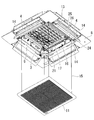
室内ユニット1は、ケース本体2が天井に埋込まれて設置される。ケース本体2の内部には、図1に示すように、熱交換器7、ドレンパン10、モータ5、送風機6、ベルマウス12等が内蔵され、このケース本体2の下部には天井面に露出するパネル部8が装着される。
天井埋込み型空気調和機(以下「空気調和機」という。)は、室内ユニット1と、室外ユニット(図示せず。)と、室内ユニット1及び室外ユニットとを結ぶ冷媒配管(図示せず。)などを備える。
室内ユニット1は、ケース本体2が天井に埋込まれて設置される。ケース本体2の内部には、図1に示すように、熱交換器7、ドレンパン10、モータ5、送風機6、ベルマウス12等が内蔵され、このケース本体2の下部には天井面に露出するパネル部8が装着される。
図1及び図2に示すように、室内ユニット1の下面中央部には吸込み口3が形成され、この吸込み口3に隣接した位置に、室内ユニット1の下面外周部に沿って一方向に長い吹出し口4が形成される。吸込み口3には、吸込みグリル11と、吸込みグリル11の上方にフィルタ13とが設置される。ドレンパン10は、熱交換器7の下部に設けられ、熱交換器7から滴下するドレン水を受ける。ベルマウス12は、ドレンパン10の下部に設けられる。
空気調和機が運転すると、図示しない室外ユニットからの冷媒が熱交換器7を循環し、モータ5によって送風機6が駆動される。送風機6の駆動によって、室内空気が吸込み口3から吸込みグリル11、フィルタ13を通り、ベルマウス12に案内されて送風機6へ吸入される。そして、送風機6から吹き出された空気は、熱交換器7を通過することで、冷却又は加熱され、その後、吹出し口4から室内へ吹き出される。
ルーバ14は、吹出し口4の形状に合わせて一方向に長く、ルーバ14は、長手方向に対して平行な軸周りに回動する。これにより、ルーバ14の向きが変更されることによって、吹出し口4から吹き出される空気流が上向きとなったり又は下向きとなったりする。
フィルタ13は、吸入される空気に含まれる塵埃等を除去する。フィルタ13は、吸込み口3と同様に四角形状を有し、吸込み口3の中央付近に配置される。また、吸込みグリル11の枠部の四隅には、吸込みグリル11を昇降させるワイヤ15が配置されている。
本実施形態に係る室内ユニット1は、フィルタ清掃ユニット16を備える。図2に示すように、フィルタ清掃ユニット16は、フィルタ13の下面においてパネル部8に設置されており、フィルタ13における一方向の1辺の長さと同等又はそれよりも長いブラシ17を有する。フィルタ清掃ユニット16のブラシ17がフィルタ13の一端側の辺から他端側の辺へフィルタ13の表面に接触ながら移動することで、フィルタ13に付着した塵埃を除去する。フィルタ清掃ユニット16は、運転制御に関する制御信号に基づいて運転を開始する。
図2に示すように、フィルタ清掃ユニット16は、パネル部8に着脱可能に設置されるフレーム部9と、フレーム部9に設置されたブラシ17、ブラシ固定部21及びモータ24等を備える。
フレーム部9は、吸込み口3と同様に四角形状を有し、吸込み口3の中央付近に配置される。フレーム部9には、フィルタ13が設置され、フレーム部9は、パネル部8に取り付けられたり、パネル部8から取り外されたりすることができる。
ブラシ17は、一方向に長い軸材を有し、軸材の外周面において軸方向の一端から他端にかけて多数の毛が配置される。ブラシ17は、両端部のそれぞれに、ピニオンギアと噛み合うブラシ回転用ギア(図示せず。)が設置されている。また、ブラシ17は、両端部おいてブラシ固定部21によって支持される。
図2に示すように、ブラシ固定部21は、ブラシ17の軸方向と平行な方向に長い部材であり、内側にブラシ17を収容する。ブラシ固定部21は、ブラシ17を囲む形状を有しており、フィルタ13側にてブラシ17を露出させる。ブラシ固定部21には、長手方向両端部に一つずつ合計二つのピニオンギア(図示せず。)が回転可能に設置されている。ブラシ固定部21は、ピニオンギアを介してラックギア(図示せず。)に支持される。ブラシ固定部21がラックギアに沿って移動することによって、ブラシ固定部21及びブラシ17がフィルタ13の表面に沿ってフィルタ13の一端側の辺から他端側の辺にかけて移動する。
ブラシ固定部21は、フィルタ13の一方向の両側でピニオンギアとラックギアによって支持されているため、ブラシ固定部21とブラシ17が確実に移動する。
ピニオンギアは、ブラシ固定部21の両端部にそれぞれ設置されている。ピニオンギアは、ラックギアと噛み合う。ブラシ固定部21が移動することによって、ピニオンギアは、ラックギア上を移動してラックギアから伝達された力によって従動的に回転する。ラックギアは、フィルタ13の外側において、軸方向がブラシ17の軸方向とは垂直方向になるように設置される。ラックギアの長さは、フィルタ13の1辺の長さと同等又はそれよりも長い。
ブラシ回転用ギアは、各ピニオンギアに対応して一つずつ設けられ、ピニオンギアに噛み合っている。ピニオンギアが回転することによって、ブラシ回転用ギアがピニオンギアから伝達された力によって従動的に回転する。その結果、ブラシ回転用ギアに設置されたブラシ17が回転し、ブラシ17の移動と共にブラシ17が回転する。
また、ピニオンギアは、モータ24と連結されておらず、従動的に動作する部材である。本実施形態では、ピニオンギアがブラシ固定部21に設置されているため、特許文献1と異なり、二つのピニオンギアを連結する推進軸が不要である。
図2に示すように、モータ24、シャフト25及びナット26などからなる駆動機構は、フィルタ13の1辺に沿って1組のみ設置されればよい。
モータ24は、フィルタ清掃ユニット16のフレーム部9に固定設置される。モータ24は、シャフト25と連結されており、モータ24が駆動することによってシャフト25が軸周りに回転する。シャフト25は、一方向に長い軸材であり、軸材の外周面に雄ねじが形成され、ナット26が噛み合わされている。シャフト25は、軸方向がブラシ17の軸方向に対して垂直方向となるように、すなわち、ラックギアと平行方向に設置される。シャフト25は、フィルタ13における一方向の1辺の長さと同等又はそれよりも長い。
ナット26は、内周面にシャフト25の雄ねじと噛み合う雌ねじが形成されている。ナット26は、シャフト25の軸周りに回転しないようにブラシ固定部21と接続されている。ナット26は、ブラシ固定部21に対して固定されていないが、ナット26はブラシ固定部21を押すことができるようにブラシ固定部21と接続されている。これにより、シャフト25が回転することによって、ナット26が移動し、ナット26がブラシ固定部21を押し、シャフト25の軸方向に沿って移動する。シャフト25の回転方向を変更することによって、ナット26及びブラシ固定部21の進行方向を変更できる。
なお、上述した例では、シャフト25に雄ねじが形成され、ナット26に雌ねじが形成されて組み合わされた例について説明したが、本発明はこの例に限定されない。例えば、シャフト25とナット26の組み合わせによってボールねじ機構となるように、シャフト25とナット26が構成されてもよい。
本実施形態において、モータ24は一つのみ設置すればよく、簡易な構造でブラシ17を移動させることができる。
次に、図3~図9を参照してシャフト25及びナット26について説明する。
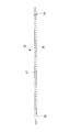
図3に示すように、シャフト25は、軸部材27と、ワイヤ28と、留め具29などを備える。
図3に示すように、シャフト25は、軸部材27と、ワイヤ28と、留め具29などを備える。
軸部材27は、断面が例えば円形状であり、外周面においてワイヤ28が巻回される。軸部材27の外周面においてワイヤ28が巻回される部分は、一端から他端にかけてほぼ同一の太さを有する。
ワイヤ28は、軸部材27よりも直径が細い線状部材であり、軸部材27の外周面に螺旋状に巻回されて配置される。ワイヤ28のピッチは、ワイヤ28の直径よりも長くなるように巻回される。軸部材27の外周面に三角ねじを形成した場合に比べてピッチが広くなるため、シャフト25の軸周りの回転数を従来と同一にした場合でも、ナット26の軸方向の移動速度を高めることができる。
留め具29は、ワイヤ28を軸部材27に対して固定する部材であり、ワイヤ28の両端部にそれぞれ設置される。留め具29によって、軸部材27の端部とワイヤ28が互いに強固に固定される。
ワイヤ28は、軸部材27に対して両端部のみにおいて固定され、両端部以外では固定されずに設置される。なお、ワイヤ28は、軸部材27に対して一端から他端にかけて軸方向に沿って全ての部分で固定されてもよい。この場合、ワイヤ28は、接着剤等によって軸部材27に対して軸方向に沿って固定される。
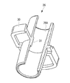
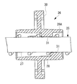
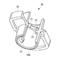
図4及び図5に示すように、ナット26は、円筒状部材であり、一端から他端にかけて貫通した貫通孔26Aが形成される。ナット26の内部、すなわち、貫通孔26Aの内部には、シャフト25が配置される。
ナット26の外周面には、ナット26の径方向に突出したフランジ30が設けられてもよい。フランジ30は、板状部材であり、ブラシ固定部21との接続に用いられる。
ナット26の内周面には、ワイヤ28のピッチ間に配置される突起部31が形成されている。シャフト25に螺旋状に設けられたワイヤ28は、ナット26の内周面に形成された突起部31と噛み合う。これにより、シャフト25が軸周りに回転することによって、ワイヤ28に沿って、ナット26の突起部31がスライドすることから、ナット26がシャフト25の軸方向に沿って移動する。その結果、ナット26が接続されたブラシ固定部21が、シャフト25の軸方向に沿って、フィルタ13の一方向に対して垂直方向に移動する。
突起部31は、例えばシャフト25の周方向に沿った長さよりもシャフト25の軸方向に沿った長さのほうが長い。これにより、突起部31の周方向の長さが短いことから、シャフト25の回転時において、シャフト25の軸部材27の外周面と突起部31の先端部との接触部分における摩擦を低減できる。
また、突起部31は、ナット26の軸方向中間部分に一つのみ形成されている。これにより、ナット26は、突起部31によって、軸方向中間部分でシャフト25に支持される。その結果、ナット26がバランス良く支持されて、ナット26が軸方向の端部のいずれか一方に傾きにくくなる。そのため、シャフト25が軸周りに回転したとき、ナット26がシャフト25に沿って安定して移動しやすい。
図6~図9に示すように、ナット26の貫通孔26Aの内周面には、複数の突起部31が設けられてもよい。例えば、4つの突起部31が設けられる場合、それぞれの突起部31は内周面の周方向に沿って90°間隔で配置される。また、シャフト25の軸方向に対するワイヤ28の角度に合わせて、それぞれの突起部31がナット26の内周面において螺旋状に配置される。すなわち、突起部31は、ナット26の軸方向において異なる位置に配置される。これにより、ナット26は、複数の位置でシャフト25に支持され、ナット26がシャフト25の外周面に対して安定的に支持される。
また、図4~図7で示した上記実施形態及び変形例では、突起部31がシャフト25の軸方向に沿った長さが周方向に沿った長さに比べて長い場合について説明したが、図8及び図9に示すように、突起部31は、シャフト25の周方向に沿った長さが軸方向に沿った長さに比べて長く形成されてもよい。これにより、シャフト25の回転方向において、接触長さが長いため、ナット26がシャフト25の外周面に対して安定的に支持される。
以上、本実施形態によれば、軸部材27の外周面に三角ねじを形成した場合に比べてピッチが広くなるため、シャフト25の軸周りの回転数を従来と同一にした場合でも、ナット26の軸方向の移動速度を高めることができる。
上記実施形態及び変形例では、軸部材27の外周面に三角ねじを形成した場合に比べてピッチを広くするため、シャフト25は、軸部材27と、軸部材27の外周面に螺旋状に設置されるワイヤ28などを備えるとしたが、本発明はこの例に限定されない。例えば、シャフト25は、三角ねじを形成した場合に比べてピッチが広い台形ねじが外周面に形成されてもよい。本発明に係る台形ねじは、山部の幅に比べて谷部の幅が広い。この場合も、シャフト25の軸周りの回転数を従来と同一にした場合でも、ナット26の軸方向の移動速度を高めることができる。
1 :室内ユニット
2 :ケース本体
3 :吸込み口
4 :吹出し口
5 :モータ
6 :送風機
7 :熱交換器
8 :パネル部
9 :フレーム部
10 :ドレンパン
11 :吸込みグリル
12 :ベルマウス
13 :フィルタ
14 :ルーバ
15 :ワイヤ
16 :フィルタ清掃ユニット
17 :ブラシ
21 :ブラシ固定部
24 :モータ
25 :シャフト
26 :ナット
26A :貫通孔
27 :軸部材
28 :ワイヤ
29 :留め具
30 :フランジ
31 :突起部
2 :ケース本体
3 :吸込み口
4 :吹出し口
5 :モータ
6 :送風機
7 :熱交換器
8 :パネル部
9 :フレーム部
10 :ドレンパン
11 :吸込みグリル
12 :ベルマウス
13 :フィルタ
14 :ルーバ
15 :ワイヤ
16 :フィルタ清掃ユニット
17 :ブラシ
21 :ブラシ固定部
24 :モータ
25 :シャフト
26 :ナット
26A :貫通孔
27 :軸部材
28 :ワイヤ
29 :留め具
30 :フランジ
31 :突起部
Claims (7)
- フィルタの一方向に沿って設置されたブラシと、
モータと、
軸方向が前記フィルタの前記一方向に対して垂直方向となるように設置され、前記モータと接続されて、前記モータによって軸周りに回転するシャフトと、
前記シャフトと結合され、前記シャフトの軸周りの回転によって前記シャフトの軸方向に沿って移動するナットと、
前記フィルタの前記一方向に沿って設置され、前記ナットと接続されつつ、前記ブラシが固定されたブラシ固定部と、
を備え、
前記シャフトは、
軸部材と、
前記軸部材の外周面に螺旋状に巻回された線状部材と、
を有し、
前記ナットの内周面には、前記線状部材のピッチ間に配置される突起部が形成されているフィルタ清掃ユニット。 - 前記突起部は、前記シャフトの周方向に沿った長さよりも前記シャフトの軸方向に沿った長さが長い請求項1に記載のフィルタ清掃ユニット。
- 前記突起部は、前記ナットの軸方向中間部分に形成されている請求項2に記載のフィルタ清掃ユニット。
- 前記突起部は、前記シャフトの軸方向に沿った長さよりも前記シャフトの周方向に沿った長さが長い請求項1に記載のフィルタ清掃ユニット。
- 前記突起部は、前記ナットの前記内周面の周方向に沿って複数配置されている請求項1から4のいずれか1項に記載のフィルタ清掃ユニット。
- フィルタの一方向に沿って設置されたブラシと、
モータと、
軸方向が前記フィルタの前記一方向に対して垂直方向となるように設置され、前記モータと接続されて、前記モータによって軸周りに回転するシャフトと、
前記シャフトと結合され、前記シャフトの軸周りの回転によって前記シャフトの軸方向に沿って移動するナットと、
前記フィルタの前記一方向に沿って設置され、前記ナットと接続されつつ、前記ブラシが固定されたブラシ固定部と、
を備え、
前記シャフトは、外周面に台形ねじが形成されているフィルタ清掃ユニット。 - 請求項1から6のいずれか1項に記載のフィルタ清掃ユニットを備える空気調和機。
Applications Claiming Priority (2)
| Application Number | Priority Date | Filing Date | Title |
|---|---|---|---|
| JP2018124771A JP7330674B2 (ja) | 2018-06-29 | 2018-06-29 | フィルタ清掃ユニット及び空気調和機 |
| JP2018-124771 | 2018-06-29 |
Publications (1)
| Publication Number | Publication Date |
|---|---|
| WO2020003773A1 true WO2020003773A1 (ja) | 2020-01-02 |
Family
ID=68986302
Family Applications (1)
| Application Number | Title | Priority Date | Filing Date |
|---|---|---|---|
| PCT/JP2019/018939 Ceased WO2020003773A1 (ja) | 2018-06-29 | 2019-05-13 | フィルタ清掃ユニット及び空気調和機 |
Country Status (2)
| Country | Link |
|---|---|
| JP (1) | JP7330674B2 (ja) |
| WO (1) | WO2020003773A1 (ja) |
Families Citing this family (1)
| Publication number | Priority date | Publication date | Assignee | Title |
|---|---|---|---|---|
| JP7661111B2 (ja) * | 2021-04-30 | 2025-04-14 | 三菱重工サーマルシステムズ株式会社 | フィルタ清掃ユニット及び空気調和機 |
Citations (3)
| Publication number | Priority date | Publication date | Assignee | Title |
|---|---|---|---|---|
| JP2010096499A (ja) * | 2005-07-04 | 2010-04-30 | Mitsubishi Heavy Ind Ltd | 室内機ユニットおよび空気調和機 |
| JP2012032080A (ja) * | 2010-07-30 | 2012-02-16 | Mitsubishi Electric Corp | エアフィルタ、このエアフィルタの清掃装置及びこれらを備えた空気調和機 |
| JP2013053846A (ja) * | 2012-11-12 | 2013-03-21 | Mitsubishi Heavy Ind Ltd | 室内機ユニットおよび空気調和機 |
Family Cites Families (5)
| Publication number | Priority date | Publication date | Assignee | Title |
|---|---|---|---|---|
| JP2693602B2 (ja) * | 1989-11-17 | 1997-12-24 | アスモ株式会社 | 送りねじ装置 |
| JP2548123Y2 (ja) * | 1991-02-01 | 1997-09-17 | 富士ゼロックス株式会社 | コロトロンのクリーニング装置 |
| JP2005069430A (ja) * | 2003-08-27 | 2005-03-17 | Kokuei Kogyo:Kk | 直線移動装置 |
| JP4756987B2 (ja) * | 2005-10-18 | 2011-08-24 | 京セラミタ株式会社 | 帯電器のワイヤー清掃装置 |
| JP5520878B2 (ja) * | 2011-04-28 | 2014-06-11 | 京セラドキュメントソリューションズ株式会社 | 移動体の往復機構、清掃機構、露光装置および画像形成装置 |
-
2018
- 2018-06-29 JP JP2018124771A patent/JP7330674B2/ja active Active
-
2019
- 2019-05-13 WO PCT/JP2019/018939 patent/WO2020003773A1/ja not_active Ceased
Patent Citations (3)
| Publication number | Priority date | Publication date | Assignee | Title |
|---|---|---|---|---|
| JP2010096499A (ja) * | 2005-07-04 | 2010-04-30 | Mitsubishi Heavy Ind Ltd | 室内機ユニットおよび空気調和機 |
| JP2012032080A (ja) * | 2010-07-30 | 2012-02-16 | Mitsubishi Electric Corp | エアフィルタ、このエアフィルタの清掃装置及びこれらを備えた空気調和機 |
| JP2013053846A (ja) * | 2012-11-12 | 2013-03-21 | Mitsubishi Heavy Ind Ltd | 室内機ユニットおよび空気調和機 |
Also Published As
| Publication number | Publication date |
|---|---|
| JP7330674B2 (ja) | 2023-08-22 |
| JP2020003168A (ja) | 2020-01-09 |
Similar Documents
| Publication | Publication Date | Title |
|---|---|---|
| JP7679164B2 (ja) | フィルタ清掃ユニット及び空気調和機 | |
| EP2574859B1 (en) | Indoor unit and air conditioner | |
| CN1246647C (zh) | 空调机 | |
| JP4523578B2 (ja) | 空気調和機のフィルタ清掃機構 | |
| JP7490330B2 (ja) | フィルタ清掃ユニット及び空気調和機 | |
| WO2020004042A1 (ja) | フィルタ清掃ユニット及び空気調和機 | |
| EP3587942A1 (en) | Filter cleaning unit and air conditioner | |
| EP3587940A1 (en) | Filter cleaning unit and conditioner | |
| JP7330674B2 (ja) | フィルタ清掃ユニット及び空気調和機 | |
| JP5108674B2 (ja) | 空調装置 | |
| EP1878976A1 (en) | Air conditioner | |
| JP7661111B2 (ja) | フィルタ清掃ユニット及び空気調和機 | |
| JP2016125704A (ja) | 空気調和機 | |
| WO2019244750A1 (ja) | フィルタ清掃ユニット及び空気調和機 | |
| JP7539759B2 (ja) | フィルタ清掃ユニット及び空気調和機 | |
| WO2019244545A1 (ja) | フィルタ清掃ユニット及び空気調和機 | |
| CN211400009U (zh) | 空调室内机及具有其的空调系统 | |
| JP5062115B2 (ja) | 空気調和装置の室内機 | |
| JP2020146648A (ja) | 室内機ユニットおよび空気調和機 | |
| JP7739036B2 (ja) | フィルタ清掃ユニット及び空気調和機 | |
| CN120627392B (zh) | 一种出风量稳定的新风交换机 | |
| CN216522059U (zh) | 滤网装置、室内机和空调器 | |
| JP2008134056A (ja) | 空気調和機 | |
| JP2007315653A (ja) | 空気調和機用回転ロータと空気調和機 |
Legal Events
| Date | Code | Title | Description |
|---|---|---|---|
| 121 | Ep: the epo has been informed by wipo that ep was designated in this application |
Ref document number: 19826366 Country of ref document: EP Kind code of ref document: A1 |
|
| NENP | Non-entry into the national phase |
Ref country code: DE |
|
| 32PN | Ep: public notification in the ep bulletin as address of the adressee cannot be established |
Free format text: NOTING OF LOSS OF RIGHTS PURSUANT TO RULE 112(1) EPC (EPO FORM 1205A DATED 29/03/2021) |
|
| 122 | Ep: pct application non-entry in european phase |
Ref document number: 19826366 Country of ref document: EP Kind code of ref document: A1 |