WO2020003703A1 - 画像符号化装置、画像復号装置、画像符号化方法、画像復号方法、コンピュータプログラム - Google Patents
画像符号化装置、画像復号装置、画像符号化方法、画像復号方法、コンピュータプログラム Download PDFInfo
- Publication number
- WO2020003703A1 WO2020003703A1 PCT/JP2019/016614 JP2019016614W WO2020003703A1 WO 2020003703 A1 WO2020003703 A1 WO 2020003703A1 JP 2019016614 W JP2019016614 W JP 2019016614W WO 2020003703 A1 WO2020003703 A1 WO 2020003703A1
- Authority
- WO
- WIPO (PCT)
- Prior art keywords
- dimensional vector
- quantization
- decoding
- encoding
- vector
- Prior art date
- Legal status (The legal status is an assumption and is not a legal conclusion. Google has not performed a legal analysis and makes no representation as to the accuracy of the status listed.)
- Ceased
Links
Images




















Classifications
-
- H—ELECTRICITY
- H04—ELECTRIC COMMUNICATION TECHNIQUE
- H04N—PICTORIAL COMMUNICATION, e.g. TELEVISION
- H04N19/00—Methods or arrangements for coding, decoding, compressing or decompressing digital video signals
- H04N19/10—Methods or arrangements for coding, decoding, compressing or decompressing digital video signals using adaptive coding
- H04N19/102—Methods or arrangements for coding, decoding, compressing or decompressing digital video signals using adaptive coding characterised by the element, parameter or selection affected or controlled by the adaptive coding
- H04N19/124—Quantisation
- H04N19/126—Details of normalisation or weighting functions, e.g. normalisation matrices or variable uniform quantisers
-
- H—ELECTRICITY
- H04—ELECTRIC COMMUNICATION TECHNIQUE
- H04N—PICTORIAL COMMUNICATION, e.g. TELEVISION
- H04N19/00—Methods or arrangements for coding, decoding, compressing or decompressing digital video signals
- H04N19/46—Embedding additional information in the video signal during the compression process
- H04N19/463—Embedding additional information in the video signal during the compression process by compressing encoding parameters before transmission
-
- H—ELECTRICITY
- H04—ELECTRIC COMMUNICATION TECHNIQUE
- H04N—PICTORIAL COMMUNICATION, e.g. TELEVISION
- H04N19/00—Methods or arrangements for coding, decoding, compressing or decompressing digital video signals
- H04N19/60—Methods or arrangements for coding, decoding, compressing or decompressing digital video signals using transform coding
- H04N19/61—Methods or arrangements for coding, decoding, compressing or decompressing digital video signals using transform coding in combination with predictive coding
-
- H—ELECTRICITY
- H04—ELECTRIC COMMUNICATION TECHNIQUE
- H04N—PICTORIAL COMMUNICATION, e.g. TELEVISION
- H04N19/00—Methods or arrangements for coding, decoding, compressing or decompressing digital video signals
- H04N19/70—Methods or arrangements for coding, decoding, compressing or decompressing digital video signals characterised by syntax aspects related to video coding, e.g. related to compression standards
-
- H—ELECTRICITY
- H04—ELECTRIC COMMUNICATION TECHNIQUE
- H04N—PICTORIAL COMMUNICATION, e.g. TELEVISION
- H04N19/00—Methods or arrangements for coding, decoding, compressing or decompressing digital video signals
- H04N19/90—Methods or arrangements for coding, decoding, compressing or decompressing digital video signals using coding techniques not provided for in groups H04N19/10-H04N19/85, e.g. fractals
- H04N19/94—Vector quantisation
Definitions
- the present invention relates to an image encoding / decoding technique.
- HEVC High Efficiency Video Coding
- HEVC High Efficiency Video Coding
- a basic block having a size larger than that of a conventional macroblock (16 ⁇ 16 pixels) is employed to improve coding efficiency.
- This large-sized basic block is called CTU (Coding @ Tree @ Unit), and its size is 64 ⁇ 64 pixels at the maximum.
- the CTU is further divided into sub-blocks that are units for performing prediction and conversion.
- Patent Literature 1 discloses a technique for encoding such a quantization matrix.
- VVC Very Video Coding
- HEVC High Efficiency Video Coding
- HEVC supports only four types of orthogonal transforms, 4 ⁇ 4, 8 ⁇ 8, 16 ⁇ 16, and 32 ⁇ 32, but VVC subdivides these into binary and ternary trees. Blocks and orthogonal transforms are under consideration and need to support more types.
- the optimal quantization matrix differs depending on the shape of the orthogonal transform. Therefore, in order to realize encoding with optimal image quality, it is necessary to set a quantization matrix suitable for each orthogonal transform.
- the present invention provides a technique for reducing the amount of data for obtaining a quantization matrix suitable for orthogonal transform.
- One embodiment of the present invention provides a first one-dimensional vector having M (M is an integer of 2 or more) elements and a second one-dimensional vector having N (N is an integer of 2 or more) elements.
- the amount of data for obtaining a quantization matrix suitable for orthogonal transform can be reduced.
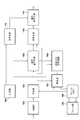
- FIG. 2 is a block diagram illustrating a functional configuration example of the image encoding device.
- FIG. 3 is a block diagram illustrating a functional configuration example of the image decoding device. 9 is a flowchart of an encoding process. 15 is a flowchart of a decoding process.
- FIG. 2 is a block diagram illustrating a hardware configuration example of a computer device.
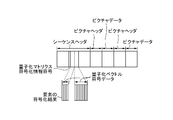
- FIG. 3 is a diagram showing a configuration example of a bit stream.
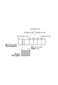
- FIG. 3 is a diagram showing a configuration example of a bit stream.
- FIG. 3 is a diagram showing a configuration example of a bit stream.
- FIG. 3 is a diagram showing a configuration example of a bit stream.
- FIG. 5 is a diagram illustrating an example of a quantization vector for generating a quantization matrix.
- FIG. 5 is a diagram illustrating an example of a quantization vector for generating a quantization matrix.
- FIG. 5 is a diagram illustrating an example of a quantization vector for generating a quantization matrix.
- FIG. 5 is a diagram illustrating an example of a quantization vector for generating a quantization matrix.
- FIG. 5 is a diagram illustrating an example of a quantization vector for generating a quantization matrix.
- FIG. 5 is a diagram illustrating an example of a quantization vector for generating a quantization matrix.
- FIG. 5 is a diagram illustrating an example of a quantization vector for generating a quantization matrix.
- FIG. 5 is a diagram illustrating an example of a quantization vector for generating a quantization matrix.
- FIG. 5 is a diagram illustrating an example of a quantization vector for generating a quantization matrix.
- FIG. 5 is a diagram illustrating an example of a quantization vector for generating a quantization matrix.
- FIG. 5 is a diagram illustrating an example of a quantization vector for generating a quantization matrix.
- FIG. 5 is a diagram illustrating an example of a quantization vector for generating a quantization matrix.
- FIG. 5 is a diagram illustrating an example of a quantization vector for generating a quantization matrix.
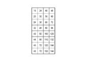
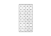
- the figure which shows an example of a quantization matrix. The figure which shows an example of a quantization matrix.
- the figure which shows an example of a quantization matrix. which shows an example of a quantization matrix.
- the figure which shows an example of a quantization matrix The figure which shows an example of a quantization matrix.
- the dividing unit 102 divides an input image into a plurality of basic blocks (CTU).
- the input image may be an image of each frame that constitutes a moving image captured by the imaging device, may be a still image that is periodically or irregularly captured by the imaging device, or may be a single image. Image. Further, such an input image may be obtained directly or indirectly from an imaging device, or may be obtained from a device holding an input image group.
- the size of the basic block is not limited to a specific size, and may be an arbitrary size having a maximum size of, for example, 64 pixels ⁇ 64 pixels.
- the prediction unit 104 divides the basic block into a plurality of sub-blocks (blocks smaller in size than the basic block), and performs intra-frame prediction (intra prediction), inter-frame prediction (inter prediction), and the like on a sub-block basis. Generate a prediction image. Then, the prediction unit 104 obtains a difference between the input image newly input from the division unit 102 and the prediction image in units of sub-blocks as a prediction error, and calculates the prediction error and information necessary for prediction (for example, a sub-block division method, Prediction mode, motion vector, etc.).
- the generation unit 103 includes a one-dimensional vector (quantized vector) having M (M is an integer of 2 or more) elements and a one-dimensional vector (quantized vector) having N (N is an integer of 2 or more) elements. ) Is used to generate a quantization matrix having a size of M ⁇ N.
- the quantization vector used to generate the quantization matrix may be acquired by any acquisition method.
- the quantization matrix refers to a matrix having a component for weighting a transform coefficient after performing an orthogonal transform according to a frequency component. Note that the quantization matrix may be called a quantization scaling list.
- the generation unit 103 may obtain the quantization vector generated by the user specifying the value of each element, or may obtain the quantization vector generated according to the image characteristics of the input image. , A quantization vector having an element for which an initial value is set may be obtained.
- Transform / quantization section 105 generates a transform coefficient group for each sub-block by performing orthogonal transform on the prediction error for each sub-block. Then, the transform / quantization unit 105 performs quantization on the transform coefficient group of each sub-block using the quantization matrix generated by the generation unit 103, thereby obtaining a quantized transform coefficient group for each sub-block.
- the inverse quantization / inverse transform unit 106 performs inverse quantization on the quantized transform coefficient group for each sub-block using the quantization matrix generated by the generation unit 103, and thereby obtains the transform coefficient for each sub-block. Create a group. Then, the inverse quantization / inverse transform unit 106 performs an inverse orthogonal transform on the transform coefficient group of each sub-block, thereby generating a prediction error of each sub-block.
- the reproduction unit 107 uses the prediction information output from the prediction unit 104 to generate a predicted image by appropriately referring to a reproduced image group stored in the frame memory 108. Then, the reproducing unit 107 generates (reproduces) a reproduced image from the predicted image and the prediction error of each sub-block obtained by the inverse quantization / inverse transforming unit 106, and stores the generated reproduced image in the frame memory 108. Store.
- the filter unit 109 performs an in-loop filter process such as a deblocking filter and a sample adaptive offset on each of the reproduced images stored in the frame memory 108, and outputs the processed images to the frame memory 108.
- the output destination of the reproduced image by the filter unit 109 is not limited to a specific output destination.
- the reproduced image may be output to an external device via a network to which the image encoding device is connected.
- the encoding unit 110 encodes the quantized transform coefficient group quantized by the transform / quantization unit 105 and the prediction information output from the prediction unit 104, thereby obtaining the quantized transform coefficient group. Encoded data including an encoding result and an encoding result of prediction information is generated.
- the encoding unit 113 encodes and encodes the quantization vectors (the quantization vector having M elements and the quantization vector having N elements) used by the generation unit 103 to generate the quantization matrix. Generate data.
- the integrated encoding unit 111 generates a bit stream in which the encoded data generated by the encoding unit 110 and the encoded data generated by the encoding unit 113 are integrated, and outputs the generated bit stream. .
- the output destination of the bit stream is not limited to a specific output destination.
- the bit stream may be output to a memory included in the image encoding device, may be output to an external device via a network to which the image encoding device is connected, or may be used for broadcasting. It may be transmitted to the outside.
- the generation unit 103 generates a quantization matrix prior to the encoding process on the input image (for example, prior to the quantization process using the quantization matrix).
- the generation unit 103 generates a quantization matrix having a size corresponding to the size of the sub-block to be coded.
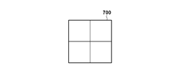
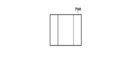
- FIGS. 7A to 7F show an example of the types of sub-block division.
- FIG. 7B shows an example of a conventional square sub-block division, in which a basic block 700 of 8 ⁇ 8 pixels is divided into sub-blocks of 4 ⁇ 4 pixels.
- FIGS. 7C to 7F show examples of the types of rectangular sub-block division.
- the basic block 700 of 8 pixels ⁇ 8 pixels is divided into sub-blocks of 4 pixels (horizontal direction) ⁇ 8 pixels (vertical direction).
- the basic block 700 of 8 pixels ⁇ 8 pixels is divided into units of 8 pixels (horizontal direction) ⁇ 4 pixels (vertical direction).
- a basic block 700 of 8 pixels ⁇ 8 pixels is a sub-block of 2 pixels (horizontal direction) ⁇ 8 pixels (vertical direction), a sub-block of 4 pixels (horizontal direction) ⁇ 8 pixels (vertical direction), It is divided into sub-blocks of pixels (horizontal direction) ⁇ 8 pixels (vertical direction).
- a basic block 700 of 8 pixels ⁇ 8 pixels is a sub-block of 8 pixels (horizontal direction) ⁇ 2 pixels (vertical direction), a sub-block of 8 pixels (horizontal direction) ⁇ 4 pixels (vertical direction), and 8 sub-blocks. It is divided into sub-blocks of pixels (horizontal direction) ⁇ 2 pixels (vertical direction).
- the encoding process is performed using not only a square but also a rectangular sub-block.
- the generation unit 103 obtains a quantization vector having M elements and a quantization vector having N elements, and uses these quantization vectors to obtain M ⁇ N Is generated.
- the dividing unit 102 divides a basic block of 8 pixels ⁇ 8 pixels into units of vertically long sub-blocks of 4 pixels (horizontal direction) ⁇ 8 pixels (vertical direction) as shown in FIG. 7C. .
- the generation unit 103 to generate a quantization matrix in which the number of elements in the horizontal direction is “4” and the number of elements in the vertical direction is “8”, the generation unit 103 generates a quantization vector having four elements, And a quantization vector having the elements of Using a quantization vector having four elements and a quantization vector having eight elements, a quantization matrix in which the number of elements in the horizontal direction is “4” and the number of elements in the vertical direction is “8”
- the method for generating the will be described with reference to FIGS. 8A to 8L.
- FIGS. 8A, 8C, 8E, 8G, 8I, and 8K show an example of a quantization vector 800 having four elements
- FIGS. 8B, 8D, 8F, 8H, 8J, and 8L show eight elements.
- An example of the quantization vector 801 having the following is shown.
- the numerical value described in each rectangle is the value of each element in the quantization vector.
- FIGS. 8A to 8L several examples of a method of generating a quantization matrix will be described with reference to FIGS. 8A to 8L.
- the generation unit 103 calculates the value of the i-th (1 ⁇ i ⁇ 4) element from the left in the quantization vector 800 and the value of the j-th (1 ⁇ j ⁇ 8) element in the quantization vector 801 from the left. Find the product value (product value). Then, the generation unit 103 calculates the obtained product value as the position (i, j) in the quantization matrix (the horizontal position i and the vertical position when the position of the upper left corner of the quantization matrix is (1, 1)). j) is the value of the element.
- the product value of the value of the i-th element from the left in the quantization vector 800 of FIG. 8A and the value of the j-th element from the left in the quantization vector 801 of FIG. 8B is the element at the position (i, j).
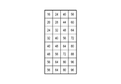
- FIG. 9A shows a quantization matrix having the value of.
- the generation unit 103 calculates the value of the i-th (1 ⁇ i ⁇ 4) element from the left in the quantization vector 800 and the value of the j-th (1 ⁇ j ⁇ 8) element in the quantization vector 801 from the left. Find the total value. Then, the generation unit 103 sets the sum as the value of the element at the position (i, j) in the quantization matrix.
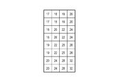
- the sum of the value of the i-th element from the left in the quantization vector 800 of FIG. 8C and the value of the j-th element from the left in the quantization vector 801 of FIG. FIG. 9B shows a quantization matrix used as the value of.
- the generation unit 103 calculates the value of the i-th (1 ⁇ i ⁇ 4) element from the left in the quantization vector 800 and the value of the j-th (1 ⁇ j ⁇ 8) element in the quantization vector 801 from the left. Find the total value. Then, the generation unit 103 sets the value obtained by adding the specified value to the total value as the value of the element at the position (i, j) in the quantization matrix.
- the prescribed value “16” is added to the sum of the value of the i-th element from the left of the quantization vector 800 in FIG. 8E and the value of the j-th element from the left of the quantization vector 801 in FIG. 8F.
- FIG. 9C shows a quantization matrix in which the value is the value of the element at the position (i, j).
- the generation unit 103 calculates the value of the i-th (1 ⁇ i ⁇ 4) element from the left in the quantization vector 800 and the value of the j-th (1 ⁇ j ⁇ 8) element in the quantization vector 801 from the left. Find the product value (product value). Then, the generation unit 103 calculates the value obtained by adding the specified value to the obtained product value to the position (i, j) in the quantization matrix (the horizontal It is the value of the element at the directional position i and the vertical position j).
- FIG. 9D shows a quantization matrix in which the values are the values of the elements at the position (i, j).
- the encoding unit 113 encodes each of the quantization vectors acquired by the generation unit 103 to generate the quantization matrix, and generates encoded data including an encoding result of each of the quantization vectors.
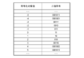
- the value of the element at the head (the leftmost element) and the difference value between the value of the element of interest other than the leftmost element and the value of the element on the left of the element of interest are encoded.
- the generation unit 103 encodes the quantization vector 800 in FIG. 8A
- the following values are acquired as encoding target values.
- the encoding unit 113 refers to the encoding table illustrated in FIG. 10A or the encoding table illustrated in FIG. 10B, specifies a binary code corresponding to each encoding target value, and specifies the specified binary code. Encode the sign.
- the configuration of the encoding table used for encoding is not limited to the encoding tables shown in FIGS. 10A and 10B.
- the value “4” of the leftmost element is used as the encoding target value.
- the present invention is not limited to this, and the difference between the value “4” of the leftmost element and a prescribed initial value (for example, 4) is calculated. It may be an encoding target value.
- the quantization vector having the number of elements “4” and the quantization vector having the number of elements “8” are encoded. Therefore, the code amount of data necessary for obtaining the quantization matrix can be reduced.
- the dividing unit 102 divides an input image into a plurality of basic blocks
- the prediction unit 104 divides a basic block into a plurality of sub-blocks, and performs intra prediction such as horizontal prediction and vertical prediction in sub-block units. Determine the prediction mode. Then, the prediction unit 104 generates a prediction image from the determined intra prediction mode and the encoded pixels, generates a prediction error from the input image and the prediction image, and outputs the prediction error to the transform / quantization unit 105. Output. On the other hand, the prediction unit 104 outputs “information necessary for prediction” such as sub-block division and intra prediction mode to the encoding unit 110 and the reproduction unit 107 as prediction information.
- the transform / quantization unit 105 generates a group of transform coefficients for each sub-block, and quantizes the group of transform coefficients using the quantization matrix generated by the generation unit 103. Generate a group of quantized transform coefficients for. For example, a quantized transform coefficient group is generated by performing a quantization process using the quantization matrix shown in FIG. 9A on the transform coefficient group of each sub-block shown in FIG. 7C.
- the inverse quantization / inverse transform unit 106 performs inverse quantization on the quantized transform coefficient group for each sub-block using the quantization matrix generated by the generation unit 103, and thereby obtains the transform coefficient for each sub-block. Create a group. Then, the inverse quantization / inverse transform unit 106 performs an inverse orthogonal transform on the transform coefficient group of each sub-block, thereby generating a prediction error of each sub-block.
- the reproduction unit 107 uses the prediction information output from the prediction unit 104 to generate a predicted image by appropriately referring to a reproduced image group stored in the frame memory 108. Then, the reproducing unit 107 generates a reproduced image from the predicted image and the prediction error of each sub-block obtained by the inverse quantization / inverse transforming unit 106, and stores the generated reproduced image in the frame memory 108.
- the filter unit 109 performs in-loop filter processing such as a deblocking filter and a sample adaptive offset on each of the reproduced images stored in the frame memory 108, and outputs the reproduced images.
- the encoding unit 110 performs entropy encoding on the quantized transform coefficient group quantized by the transform / quantization unit 105 and the prediction information output from the prediction unit 104 to obtain a quantized transform coefficient group. And coded data including the coding result of the prediction information and the coding result of the prediction information.
- the type of entropy coding is not limited to a specific type, and Golomb coding, arithmetic coding, Huffman coding, or the like can be used.
- the integrated encoding unit 111 multiplexes the encoded data generated by the encoding unit 110 and the encoded data generated by the encoding unit 113 to generate a bit stream, and outputs the generated bit stream. I do.
- FIG. 6A shows a configuration example of the bit stream according to the present embodiment.
- the sequence header includes encoded data of the quantization vector used to generate the quantization matrix, and is configured by encoding results of each element of the quantization vector.
- the quantization vector in FIG. 8A and the quantization vector in FIG. 8B have been encoded.
- the position in the bit stream of the encoded data of the quantization vector is not limited to the position shown in FIG. 8A, but may be a position in a picture header or another header.
- the quantization matrix corresponding to the quantization matrix can be updated by newly encoding the quantization vector.
- the bit stream (for example, in the sequence header) also includes information indicating a method of generating a quantization matrix from the quantization vector (for example, any of the above-described generation methods 1 to 4).
- step S301 the generation unit 103 generates a quantization matrix having a size of M ⁇ N by using a quantization vector having M elements and a quantization vector having N elements.
- step S302 the encoding unit 113 encodes each of the quantization vectors used to generate the quantization matrix in step S301 to generate encoded data.
- step S304 the dividing unit 102 divides the input image into a plurality of basic blocks.
- step S305 the prediction unit 104 selects an unselected basic block from among the plurality of basic blocks as a selected basic block. Then, the prediction unit 104 divides the selected basic block into a plurality of sub-blocks, performs prediction coding in sub-block units, obtains a prediction error, and acquires prediction information.
- step S306 the transform / quantization unit 105 generates a group of transform coefficients for each sub-block, and quantizes the group of transform coefficients using the quantization matrix generated in step S301. Generate a quantized transform coefficient group for the block.
- step S307 the inverse quantization / inverse transform unit 106 performs inverse quantization on the quantized transform coefficient group for each sub-block using the quantization matrix generated in step S301, thereby obtaining each sub-block. Is generated. Then, the inverse quantization / inverse transform unit 106 performs an inverse orthogonal transform on the transform coefficient group of each sub-block, thereby generating a prediction error of each sub-block.
- step S308 the reproducing unit 107 generates a predicted image by appropriately referring to the reproduced image group stored in the frame memory 108 using the prediction information obtained by the prediction unit 104 in step S305. Then, the reproducing unit 107 generates a reproduced image from the predicted image and the prediction error of each sub-block obtained by the inverse quantization / inverse transforming unit 106, and stores the generated reproduced image in the frame memory 108.
- step S309 the encoding unit 110 performs entropy encoding on the quantized transform coefficient group quantized in step S306 and the prediction information acquired by the prediction unit 104 in step S305, and performs encoding. Generate encrypted data. Then, the integrated encoding unit 111 multiplexes the encoded data generated by the encoding unit 110 and the encoded data such as the quantization vector generated by the encoding unit 113 in step S302 to generate a bit stream. I do.
- step S305 If the unselected basic block remains among the plurality of basic blocks, the process proceeds to step S305 via step S310. On the other hand, when all of the plurality of basic blocks have been selected as the selected basic block, the process proceeds to step S311 via step S310.
- step S311 the filter unit 109 performs in-loop filter processing such as a deblocking filter and a sample adaptive offset on each of the reproduced images stored in the frame memory 108, and outputs the processed images.
- in-loop filter processing such as a deblocking filter and a sample adaptive offset
- step S302 the one-dimensional quantization vector is encoded instead of the two-dimensional quantization matrix, thereby reducing the code amount of information necessary to obtain the quantization matrix. be able to. As a result, the data amount of the entire generated bit stream is reduced, so that the compression efficiency can be improved.
- FIG. 7C a case has been described in which a basic block of 8 pixels ⁇ 8 pixels is divided into units of vertically long sub-blocks of 4 pixels (horizontal direction) ⁇ 8 pixels (vertical direction).
- the sub-block division method is not limited to this.
- quad-tree division as shown in FIG. 7B, ternary tree division as shown in FIGS. 7E and 7F, or non-division as shown in FIG. 7A may be used.
- the generation unit 103 generates a quantization vector for a quantization matrix corresponding to the sub-block.
- the quantization vectors shown in FIGS. 8A to 8L may be applied to other types of sub-blocks. For example, for a sub-block of 8 pixels (horizontal direction) ⁇ 8 pixels (vertical direction) in FIG. 7A, the quantization vector having eight coefficients in FIG. 8B is applied for the horizontal direction and the vertical direction, respectively. That is, the vector of FIG. 8B is used twice.
- the quantization vector having four coefficients in FIG. 8A is applied for the horizontal direction and the vertical direction, respectively. That is, the vector of FIG. 8A is used twice.
- the quantization vector having eight coefficients in FIG. 8B is applied in the horizontal direction of the sub-block.
- the quantization vector having the four coefficients of FIG. 8A is applied in the vertical direction of the sub-block.
- a combination of arbitrary two coefficients among the quantization vectors having four coefficients in FIG. Apply to For example, the first two coefficients of the four coefficients in FIG. 8A may be selected. Then, the quantization vector having eight coefficients in FIG. 8B is applied in the vertical direction of the sub-block.
- information on a method of generating a quantization vector applied to each type of sub-block is also encoded so as to be generated by an image decoding device described later.
- quantized vector groups (2, 4, 8, 16, and 32) of different numbers of coefficients may be prepared in the horizontal and vertical directions, respectively, and may be encoded. In this case, an identifiable index is given to each vector. Then, the indexes of the horizontal quantization vector and the vertical quantization vector are associated with each sub-block so that the desired vector is applied to the sub-block.
- ⁇ Modification> all the quantization vectors used for generating the quantization matrix are encoded. This is to notify the decoding side of the quantization vector required for generating the quantization matrix on the encoding side.
- the decoding side decodes the other quantized vector, generates one quantized vector from the decoded other quantized vector, and generates a quantized vector from the one quantized vector and the other quantized vector.
- a matrix can be generated.
- the decoding side may be notified of the quantization vector in FIG. 8I. That is, the decoding side can generate the quantization vector of FIG. 8J from the quantization vector of FIG. 8I, and generate, for example, the quantization matrix of FIG. 9E from the quantization vector of FIG. 8J and the quantization vector of FIG. 8I. it can.
- the quantization vector in FIG. 8I is encoded without encoding the quantization vector in FIG. 8J. This makes it possible to further reduce the code amount of data required to obtain the quantization matrix of FIG. 9E. Since the quantization vector of FIG. 8I can be generated from the quantization vector of FIG. 8J by a process reverse to the above-described interpolation process, the quantization vector of FIG. May be encoded. In this case, although the amount of code applied to the quantization matrix slightly increases, finer control of the quantization matrix can be performed.
- the method of generating one quantization vector from the other quantization vector is not limited to the above-described interpolation processing.
- the quantization matrix of FIG. 9F is generated by the above-described generation method 1 using the quantization vector of FIG. 8K and the quantization vector of FIG. 8L.
- the quantization vector of FIG. 8L may not be encoded, and the quantization vector of FIG. 8K may be encoded, whereby the code amount of data necessary to obtain the quantization matrix of FIG. 9F is obtained. Can be further reduced. Since the quantization vector in FIG. 8K can be generated from the quantization vector in FIG. 8L, the quantization vector in FIG. 8K is not encoded, and the quantization vector in FIG. 8L is encoded. May be. In this case, although the amount of code applied to the quantization matrix slightly increases, finer control of the quantization matrix can be performed.
- the quantization matrix is encoded without encoding the quantization matrix.
- the quantization matrix may be selectively encoded.
- the quantization vector coding according to the present embodiment and the conventional quantization matrix coding are selectively performed by newly introducing a quantization matrix coding information code. For example, when the quantization matrix coding information code indicates “0”, the one-dimensional quantization vector coding of the present embodiment is used, and the bit stream in FIG. 6B is generated. On the other hand, when the quantization matrix coding information code indicates “1”, the conventional two-dimensional quantization matrix coding is used, and the bit stream in FIG. 6C is generated.
- the quantization matrix coding information code indicates “0”, it may indicate that “quantization matrix is not used”. In this case, neither the quantization vector nor the quantization matrix is encoded. In such an example, when the quantization matrix coding information code indicates “1”, the one-dimensional quantization vector coding of the present embodiment is used, and the bit stream of FIG. 6B is generated. . When the quantization matrix coding information code indicates “2”, the conventional two-dimensional quantization matrix coding is used, and the bit stream in FIG. 6C is generated.
- the configuration may be such that the quantization vector coding of the present embodiment and the conventional quantization matrix coding can be switched for each quantization matrix. This makes it possible to selectively realize the quantization matrix code amount reduction and the quantization matrix control.
- one-dimensional quantization vector coding may be selected when the code amount at the time of coding of a conventional two-dimensional quantization matrix is expected to be reduced by a predetermined amount or more.
- a two-dimensional quantization matrix may be employed when a quantization vector cannot completely represent a high-resolution image or the like.
- an image decoding device that decodes a bit stream generated by the image encoding device in FIG. 1 will be described.
- the image decoding device according to the present embodiment may be a device integrated with the image encoding device in FIG. 1 or may be a separate device.
- an example of a functional configuration of the image decoding device according to the present embodiment will be described with reference to the block diagram of FIG.
- the separation unit 201 obtains the bit stream generated by the image encoding device, and separates each piece of the information included in the bit stream from the bit stream. That is, the demultiplexing unit 201 separates each piece of the information included in the bit stream by performing an operation reverse to the operation performed by the unified encoding unit 111.
- bit stream may be a bit stream of an image of each frame constituting a moving image, or a bit stream of each still image that is periodically or irregularly captured by the imaging device. Alternatively, it may be a bit stream of one image. Further, such a bit stream may be obtained directly or indirectly from an image encoding device, or may be obtained from a device that holds a group of bit streams.
- the reproduction unit 209 decodes the encoded data of the quantization vector to restore (reproduce) the quantization vector, and generates a quantization matrix from the restored quantization vector.
- Information indicating a method of generating the quantization matrix from the quantization vector (for example, any of the above-described generation methods 1 to 4) is stored in the header of the above-described bit stream. Therefore, the reproducing unit 209 generates a quantization matrix from the quantization vector according to the method indicated by this information. If a method of generating a quantization vector from a quantization vector is known in advance between the image encoding device and the image decoding device, information indicating a method of generating a quantization matrix from the quantization vector is included in a header or the like. You do not need to include it.
- the decoding unit 203 decodes the encoded data including the encoding result of the quantized transform coefficient group and the encoding result of the prediction information by performing an operation reverse to the operation performed by the encoding unit 110, Acquire the quantized transform coefficient group and prediction information.
- the inverse quantization / inverse transformation unit 204 operates in the same manner as the above-described inverse quantization / inverse transformation unit 106, and performs the quantization generated by the reproduction unit 209 on the quantized transform coefficient group acquired by the decoding unit 203. By performing inverse quantization using a matrix, a group of transform coefficients for each sub-block is generated. Then, the inverse quantization / inverse transform unit 204 generates a prediction error of each sub-block by performing an inverse orthogonal transform on the transform coefficient group of each sub-block.
- the reproducing unit 205 operates in the same manner as the above-described reproducing unit 107, and generates a predicted image by appropriately referring to the reproduced image group stored in the frame memory 206 using the prediction information decoded by the decoding unit 203. Then, the reproducing unit 205 generates (reproduces) a reproduced image from the predicted image and the prediction error of each subblock obtained by the inverse quantization / inverse transforming unit 204, and stores the generated reproduced image in the frame memory 206. Store.
- the filter unit 207 operates in the same manner as the filter unit 109 described above. That is, the filter unit 207 performs in-loop filter processing such as a deblocking filter and a sample adaptive offset on each of the reproduced images stored in the frame memory 206, and outputs the reproduced images to the frame memory 206.
- the output destination of the reproduced image by the filter unit 207 is not limited to a specific output destination.
- the reproduced image may be output to an external device via a network to which the image decoding device is connected.
- the separation unit 201 obtains the bit stream in FIG. 6A and separates each piece of the information included in the bit stream from the bit stream. As a result, the separation unit 201 acquires a sequence header, encoded data including the encoded result of the quantized transform coefficient group and the encoded result of the prediction information, encoded data of the quantized vector, and the like.
- the encoded data of the quantized vector is the encoded data of the quantized vector of FIG. 8A and the encoded data of the quantized vector of FIG. 8B.
- the reproducing unit 209 decodes the encoded data of the quantized vector and restores the quantized vector of FIG. 8A and the quantized vector of FIG. 8B.
- the decoding a process opposite to the encoding of the quantization vector is performed, and the encoding target value corresponding to the binary code is specified with reference to the encoding table illustrated in FIG. 10A and the encoding table illustrated in FIG. 10B.
- the reproduction unit 209 acquires “information indicating a method of generating a quantization matrix from a quantization vector (here, the above-described generation method 1)” from the sequence header.
- the reproducing unit 209 generates the quantization matrix of FIG. 9A from the quantization vector of FIG. 8A and the quantization vector of FIG. 8B according to the generation method 1 indicated by the information.
- the encoding table used for decoding the quantization vector only needs to be used for encoding the quantization vector, and is not limited to the encoding tables shown in FIGS. 10A and 10B.
- FIGS. 8A to 8L When the quantization vectors shown in FIGS. 8A to 8L are applied to sub-blocks other than 4 pixels (horizontal direction) ⁇ 8 pixels (vertical direction), first, a method of generating a quantization vector applied to each type of sub-block is described. Decrypts information about A quantization vector for each sub-block is generated based on the quantization vector generation method. Similarly to a sub-block of 4 pixels (horizontal direction) ⁇ 8 pixels (vertical direction), a quantization matrix corresponding to each sub-block is generated from a bit stream based on information on a generation method based on a quantization vector. .
- the operation of the decoding unit 203 is as described above.
- the inverse quantization / inverse transform unit 204 performs inverse quantization on the quantized transform coefficient group acquired by the decoding unit 203 using the quantization matrix of FIG. A transform coefficient group for each sub-block of 7C is generated. Then, the inverse quantization / inverse transform unit 204 generates a prediction error of each sub-block by performing an inverse orthogonal transform on the transform coefficient group of each sub-block.
- the operations of the reproduction unit 205 and the filter unit 207 are as described above.
- step S401 the separation unit 201 acquires a bit stream, and separates each piece of the information included in the bit stream from the bit stream.
- step S402 the reproducing unit 209 decodes the encoded data of the quantization vector to restore the quantization vector, and generates a quantization matrix from the restored quantization vector.
- step S403 the decoding unit 203 decodes the encoded data including the encoded result of the quantized transform coefficient group and the encoded result of the prediction information, and acquires the quantized transform coefficient group and the prediction information.
- step S404 the inverse quantization / inverse transformation unit 204 performs inverse quantization on the quantized transform coefficient group acquired in step S403 using the quantization matrix generated in step S402, and Generate a group of transform coefficients for the block. Then, the inverse quantization / inverse transform unit 204 generates a prediction error of each sub-block by performing an inverse orthogonal transform on the transform coefficient group of each sub-block.
- step S405 the reproducing unit 205 generates a predicted image by appropriately referring to the reproduced image group stored in the frame memory 206 using the prediction information acquired in step S403. Then, the reproducing unit 205 generates (reproduces) a reproduced image from the predicted image and the prediction error of each sub-block generated in step S404, and stores the generated reproduced image in the frame memory 206.
- step S407 the filter unit 207 performs an in-loop filter process such as a deblocking filter or a sample adaptive offset on each of the reproduced images stored in the frame memory 206, and outputs the processed images to the frame memory 206.
- an in-loop filter process such as a deblocking filter or a sample adaptive offset
- ⁇ Modification> As described above, when one of the quantization vectors required for generating the quantization matrix on the encoding side can be generated from the other, it is not necessary to encode both quantization vectors. That is, it is not necessary to encode one quantized vector and encode the other quantized vector.
- the decoding side generates another quantization vector from the decoded quantization vector, and performs quantization using the decoded quantization vector and the quantization vector generated from the decoded quantization vector. Generate a matrix.
- the encoded data of the quantized vector of FIG. 8I is obtained as the encoded data of the quantized vector
- the encoded data is decoded to obtain the quantized vector of FIG. 8I.
- the quantization vector of FIG. 8J is generated from the quantization vector of FIG. 8I by the above-described interpolation processing, and the quantization matrix of FIG. 9E is generated from the quantization vector of FIG. 8I and the quantization vector of FIG. 8J.
- the quantized vector of FIG. 8I and the encoded data of the quantized vector of FIG. 8J are obtained as the encoded data of the quantized vector. If even the quantized vector of FIG. A quantization vector can be generated.
- the configuration is such that the encoded data of the quantization vector of FIG. 8J is acquired as the encoded data of the quantization vector. It is good.
- the encoded data of the quantization vector of FIG. 8J is decoded to obtain the quantization vector
- the quantization vector of FIG. 8I is generated from the quantization vector
- the quantization matrix of FIG. 9E is generated from the quantization vector. This is the same when the encoded data of the quantized vector of FIG. 8I and the encoded data of the quantized vector of FIG. 8J are obtained as the encoded data of the quantized vector.
- the encoded data of the quantized vector of FIG. 8K is obtained as the encoded data of the quantized vector
- the encoded data is decoded to obtain the quantized vector of FIG. 8K.
- the quantization vector of FIG. 8L is generated from the quantization vector of FIG. 8K by the above-described duplicate copy
- the quantization matrix of FIG. 9F is generated from the quantization vector of FIG. 8K and the quantization vector of FIG. 8L.
- the quantized vector of FIG. 8K and the encoded data of the quantized vector of FIG. 8L are obtained as the quantized vector encoded data. If even the quantized vector of FIG. A quantization vector can be generated.
- the quantization vector of FIG. 8K can be generated from the quantization vector of FIG. 8L, the configuration for acquiring the encoded data of the quantization vector of FIG. 8L as the encoded data of the quantization vector. It is good.
- the coded data of the quantization vector of FIG. 8L is decoded to obtain the quantization vector
- the quantization vector of FIG. 8K is generated from the quantization vector
- the quantization matrix of FIG. 9F is generated from the quantization vector. This is the same also when the encoded data of the quantized vector of FIG. 8K and the encoded data of the quantized vector of FIG. 8L are acquired as the encoded data of the quantized vector.
- the quantization matrix is not encoded and the bit stream obtained by encoding the quantization vector is decoded.
- the bit stream obtained by selectively encoding the quantization matrix is decoded. No problem.
- the quantization matrix coding information code (included in the sequence header) indicates “0”, the quantization vector coding of the present embodiment is used, and the bit stream of FIG. 6B is generated. Therefore, the decoding operation as described above is performed. Thereby, the bit stream of FIG. 6B is decoded.
- the quantization matrix coding information code indicates “1”
- the conventional quantization matrix coding is used and the bit stream shown in FIG. 6C is generated. Perform the operation.
- the above-mentioned different code assignment may be used. That is, when the quantization matrix coding information code indicates “0”, it may indicate that “quantization matrix is not used”. In this case, neither the quantization vector nor the quantization matrix is encoded. In such an example, when the quantization matrix coding information code indicates “1”, the one-dimensional quantization vector coding of the present embodiment is used, and the bit stream of FIG. 6B is generated. . When the quantization matrix coding information code indicates “2”, the conventional two-dimensional quantization matrix coding is used, and the bit stream in FIG. 6C is generated.
- the configuration may be such that the quantization vector decoding of the present embodiment and the conventional quantization matrix decoding can be switched in units of quantization matrix. In this case, the decoding operation is switched in units of quantization matrix. . As a result, it is possible to decode a bit stream in which quantization matrix code amount reduction and quantization matrix control are selectively realized.
- Each functional unit shown in FIG. 1 and each functional unit shown in FIG. 2 may be implemented by hardware, but each functional unit except the frame memories 108 and 206 may be implemented by software (computer program). good.
- a computer device that can execute the computer program is applicable to the above-described image encoding device and image decoding device.
- An example of a hardware configuration of a computer device applicable to the above-described image encoding device and image decoding device will be described with reference to the block diagram of FIG.
- the CPU 501 executes various processes using computer programs and data stored in the RAM 502 and the ROM 503. Accordingly, the CPU 501 controls the operation of the entire computer device, and executes or controls the processes described above as performed by the image encoding device and the image decoding device to which the computer device is applied.
- the RAM 502 has an area for storing computer programs and data loaded from the ROM 503 and the external storage device 506, and data (such as an input image and a bit stream) externally received via an I / F (interface) 507. Further, the RAM 502 has a work area used when the CPU 501 executes various processes. As described above, the RAM 502 can appropriately provide various areas.
- the ROM 503 stores information that does not need to be rewritten, such as setting data of a computer device and a startup program.
- the operation unit 504 is configured by a user interface such as a keyboard, a mouse, and a touch panel, and can input various instructions to the CPU 501 by operating the user.
- a user interface such as a keyboard, a mouse, and a touch panel
- the display unit 505 includes a liquid crystal screen, a touch panel screen, and the like, and can display a processing result of the CPU 501 as an image, characters, or the like.
- the display unit 505 may be a projection device that projects images and characters.
- the external storage device 506 is a large-capacity information storage device such as a hard disk drive.
- the external storage device 506 stores an OS (Operating System), a computer program and data for causing the CPU 501 to execute or control each of the above-described processes performed by the image encoding device and the image decoding device.
- the computer programs stored in the external storage device 506 include computer programs for causing the CPU 501 to realize the functions of the functional units (excluding the frame memories 108 and 206) illustrated in FIGS.
- the data stored in the external storage device 506 includes information handled as known information in the above description.
- the computer programs and data stored in the external storage device 506 are appropriately loaded into the RAM 502 under the control of the CPU 501, and are processed by the CPU 501.
- the frame memories 108 and 206 can be implemented by the RAM 502 and the external storage device 506.
- the I / F 507 is an interface for performing data communication with an external device. For example, an input image or a bit stream is received via the I / F 507 and stored in the RAM 502 or the external storage device 506. You. Also, the bit stream generated by the image encoding device or the image decoded by the image decoding device is transmitted to an external device (display device, server device, or the like) via the I / F 507. good.
- the CPU 501, the RAM 502, the ROM 503, the operation unit 504, the display unit 505, the external storage device 506, and the I / F 507 are all connected to the bus 508.
- the configuration illustrated in FIG. 5 is merely an example of a hardware configuration of a computer device that can be applied to the above-described image encoding device and image decoding device, and can be appropriately changed or modified.
- the numerical values and the processing order used in the description of each of the above-described embodiments and the modified examples are merely examples.
- the encoding / decoding processing of each of the above-described embodiments and modifications is an example of encoding / decoding processing including processing of quantizing / dequantizing a sub-block using a quantization matrix.
- the present invention is not limited to the encoding / decoding processing described in each of the above embodiments and modifications.
- the present invention supplies a program for realizing one or more functions of the above-described embodiments to a system or an apparatus via a network or a storage medium, and one or more processors in a computer of the system or the apparatus read and execute the program. It can also be realized by the following processing. Further, it can be realized by a circuit (for example, an ASIC) that realizes one or more functions.
- a circuit for example, an ASIC
Landscapes
- Engineering & Computer Science (AREA)
- Multimedia (AREA)
- Signal Processing (AREA)
- Compression Or Coding Systems Of Tv Signals (AREA)
Applications Claiming Priority (2)
| Application Number | Priority Date | Filing Date | Title |
|---|---|---|---|
| JP2018-123523 | 2018-06-28 | ||
| JP2018123523A JP7090490B2 (ja) | 2018-06-28 | 2018-06-28 | 画像符号化装置、画像復号装置、画像符号化方法、画像復号方法 |
Publications (1)
| Publication Number | Publication Date |
|---|---|
| WO2020003703A1 true WO2020003703A1 (ja) | 2020-01-02 |
Family
ID=68987035
Family Applications (1)
| Application Number | Title | Priority Date | Filing Date |
|---|---|---|---|
| PCT/JP2019/016614 Ceased WO2020003703A1 (ja) | 2018-06-28 | 2019-04-18 | 画像符号化装置、画像復号装置、画像符号化方法、画像復号方法、コンピュータプログラム |
Country Status (3)
| Country | Link |
|---|---|
| JP (1) | JP7090490B2 (enExample) |
| TW (1) | TW202002634A (enExample) |
| WO (1) | WO2020003703A1 (enExample) |
Citations (2)
| Publication number | Priority date | Publication date | Assignee | Title |
|---|---|---|---|---|
| WO2007094100A1 (ja) * | 2006-02-13 | 2007-08-23 | Kabushiki Kaisha Toshiba | 動画像符号化/復号化方法及び装置並びにプログラム |
| JP2012186617A (ja) * | 2011-01-31 | 2012-09-27 | Sony Corp | 画像処理装置および方法 |
-
2018
- 2018-06-28 JP JP2018123523A patent/JP7090490B2/ja active Active
-
2019
- 2019-04-18 WO PCT/JP2019/016614 patent/WO2020003703A1/ja not_active Ceased
- 2019-04-30 TW TW108115008A patent/TW202002634A/zh unknown
Patent Citations (2)
| Publication number | Priority date | Publication date | Assignee | Title |
|---|---|---|---|---|
| WO2007094100A1 (ja) * | 2006-02-13 | 2007-08-23 | Kabushiki Kaisha Toshiba | 動画像符号化/復号化方法及び装置並びにプログラム |
| JP2012186617A (ja) * | 2011-01-31 | 2012-09-27 | Sony Corp | 画像処理装置および方法 |
Also Published As
| Publication number | Publication date |
|---|---|
| JP2020005143A (ja) | 2020-01-09 |
| JP7090490B2 (ja) | 2022-06-24 |
| TW202002634A (zh) | 2020-01-01 |
Similar Documents
| Publication | Publication Date | Title |
|---|---|---|
| KR102782659B1 (ko) | 화상 부호화 장치, 화상 부호화 방법 및 저장 매체 | |
| JP7610690B2 (ja) | 画像復号装置及び方法及びプログラム | |
| JP2023080359A (ja) | 画像復号装置、画像復号方法、及びプログラム | |
| JP2023113858A (ja) | 画像復号装置、画像復号方法、及びプログラム | |
| JP2024149754A (ja) | 画像符号化装置及び画像復号装置及びそれらの制御方法及びプログラム | |
| WO2020129489A1 (ja) | 画像符号化装置及び画像復号装置及びそれらの制御方法及びプログラム | |
| JP2025013665A (ja) | 画像符号化装置、画像符号化方法、画像復号装置、画像復号方法 | |
| WO2023181546A1 (ja) | 画像符号化装置、画像復号装置、画像符号化方法、および画像復号方法 | |
| JP7090490B2 (ja) | 画像符号化装置、画像復号装置、画像符号化方法、画像復号方法 | |
| JP7403246B2 (ja) | 画像復号装置、画像復号方法 | |
| JP2020010320A (ja) | 画像符号化装置及び画像復号装置及びそれらの制御方法及びプログラム | |
| WO2025069744A1 (ja) | 画像符号化装置、画像符号化方法、画像復号装置、画像復号方法、コンピュータプログラム | |
| JP2021150723A (ja) | 画像符号化装置、画像符号化方法、及びプログラム、画像復号装置、画像復号方法、及びプログラム | |
| WO2020183859A1 (ja) | 画像符号化装置、画像復号装置、画像符号化方法、画像復号方法、及びプログラム |
Legal Events
| Date | Code | Title | Description |
|---|---|---|---|
| 121 | Ep: the epo has been informed by wipo that ep was designated in this application |
Ref document number: 19826675 Country of ref document: EP Kind code of ref document: A1 |
|
| NENP | Non-entry into the national phase |
Ref country code: DE |
|
| 122 | Ep: pct application non-entry in european phase |
Ref document number: 19826675 Country of ref document: EP Kind code of ref document: A1 |