WO2020003685A1 - 静電容量型伸びセンサシステム - Google Patents
静電容量型伸びセンサシステム Download PDFInfo
- Publication number
- WO2020003685A1 WO2020003685A1 PCT/JP2019/015078 JP2019015078W WO2020003685A1 WO 2020003685 A1 WO2020003685 A1 WO 2020003685A1 JP 2019015078 W JP2019015078 W JP 2019015078W WO 2020003685 A1 WO2020003685 A1 WO 2020003685A1
- Authority
- WO
- WIPO (PCT)
- Prior art keywords
- elongation
- sensor
- capacitance
- sensor system
- dielectric layer
- Prior art date
- Legal status (The legal status is an assumption and is not a legal conclusion. Google has not performed a legal analysis and makes no representation as to the accuracy of the status listed.)
- Ceased
Links
Images



Classifications
-
- G—PHYSICS
- G01—MEASURING; TESTING
- G01B—MEASURING LENGTH, THICKNESS OR SIMILAR LINEAR DIMENSIONS; MEASURING ANGLES; MEASURING AREAS; MEASURING IRREGULARITIES OF SURFACES OR CONTOURS
- G01B7/00—Measuring arrangements characterised by the use of electric or magnetic techniques
- G01B7/16—Measuring arrangements characterised by the use of electric or magnetic techniques for measuring the deformation in a solid, e.g. by resistance strain gauge
Definitions
- the present invention relates to a capacitance-type elongation sensor system including a base material having elasticity and a flexible sensor element.
- a capacitance type sensor is attached to a living body or clothes, and the movement of the living body such as a respiratory rate and bending and stretching of a joint is measured.
- the capacitance type sensor when the thickness of the dielectric layer is reduced and the distance between the electrode layers is reduced by extension, the capacitance increases. At the same time, when the area of the electrode layer increases, the capacitance increases. According to the capacitance type sensor, the movement of the living body can be measured based on the change in capacitance due to expansion and contraction of the sensor.
- the capacitance of the capacitance type sensor is measured by applying an AC voltage between the electrodes.
- the measurement frequency is increased, the leakage current increases, which increases the power consumption and is not economical. If the power consumption is large, the battery is quickly consumed when driven by a battery, which is inconvenient. Conversely, when the measurement frequency is lowered, the power consumption is reduced, but it is difficult to measure the rapid movement of the living body. Therefore, it is desirable to change the measurement frequency according to the movement to be measured.
- an elastomer is used for the dielectric layer from the viewpoint of making the capacitance type sensor flexible.
- the dielectric constant of the dielectric layer changes.
- the dielectric constant of the dielectric layer is affected by a polarization structure such as electronic polarization, orientation polarization, and ionic polarization.
- additives such as a cross-linking agent, a cross-linking accelerator, and a dispersant are blended with the elastomer. When these residues are ionized by an electric field, the ions are inverted and polarization occurs (ion polarization).
- the present invention has been made in view of such circumstances, and includes a sensor element having a dielectric layer in which a change in relative dielectric constant due to a measurement frequency is small even if it contains an elastomer, and can measure movement of a living body and the like.
- An object of the present invention is to provide a simple capacitance-type elongation sensor system.
- the capacitance-type elongation sensor system of the present invention is a capacitance-type elongation sensor system including a base material having elasticity and an elongation sensor disposed on the base material, wherein the elongation sensor is an elastomer. And a sensor element having a plurality of electrode layers disposed with the dielectric layer interposed therebetween.
- the maximum relative permittivity of the dielectric layer is It is characterized by being not more than 10 times the minimum relative permittivity.
- the sensor element constituting the capacitance-type elongation sensor system of the present invention includes a dielectric layer having an elastomer and having a small change in relative dielectric constant in a measurement frequency range of 0.1 Hz to 10 kHz.
- the measurement frequency used to measure the movement of the living body is appropriately about 1 Hz to 100 Hz.
- the relative permittivity of the dielectric layer is hard to change in a range including the frequency, so that even if the measurement frequency is changed according to the movement of the living body, the capacitance is hard to change. Therefore, it is possible to set the optimum measurement frequency for the movement to be measured without changing the components of the measurement circuit, and it is possible to accurately measure various movements of the living body.
- setting the measurement frequency while avoiding the frequency at which noise is desired to be reduced facilitates compliance with EMC regulations. That is, the fact that the measurement frequency can be easily changed is also effective for noise suppression.
- the elongation sensor is arranged on a stretchable base material.
- the substrate is a supporter or the like
- the body movement can be easily measured only by wearing it, or when the substrate is clothing, by simply wearing it.
- the relative permittivity at the measurement frequency of 0.1 Hz is 10 times or less than the relative permittivity at the time of 10 kHz (10000 Hz), "in the range of 0.1 Hz to 10 kHz, The maximum relative permittivity of the dielectric layer is 10 times or less of the minimum relative permittivity.
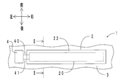
- FIG. 1 is a top view of an embodiment of a capacitance type elongation sensor system of the present invention.
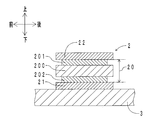
- FIG. 2 is a sectional view taken along the line II-II of FIG. 1. It is a top view of the extension sensor arranged in the substrate. It is a cross-sectional schematic diagram in the front-back direction of the stretch sensor.
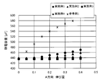
- 5 is a graph showing a change in capacitance with respect to an amount of elongation in an A direction.
- 6 is a graph showing a change in capacitance with respect to an elongation amount in a B direction.
- FIG. 1 shows a top view of the capacitance type elongation sensor system of the present embodiment.
- FIG. 2 is a sectional view taken along line II-II of FIG. In FIG. 2, the vertical direction corresponds to the thickness direction of the elongation sensor.
- the capacitance type elongation sensor system 1 includes an elongation sensor 2, a base material 3, and a control device 4.
- the left-right direction of the substrate 3 is defined as a measurement direction
- the front-rear direction is defined as a vertical direction perpendicular to the measurement direction.
- the base material 3 is compression wear (cloth using elastic fibers) and has elasticity.
- the elongation sensor 2 is disposed on the upper surface of the base member 3 so as to extend in a band shape in the left-right direction.
- the Young's modulus of the elongation sensor 2 is 20 MPa or less.
- the value of “Young's modulus ⁇ thickness” of the elongation sensor 2 is 10 times or more the value of “Young's modulus ⁇ thickness” of the substrate 3.
- the elongation sensor 2 includes a sensor element 20, an adhesive layer 21, and a protective layer 22.
- the sensor element 20 has a rectangular thin film shape.
- the length of the long side (length in the left-right direction) of the sensor element 20 is at least five times the length of the short side (length in the front-rear direction).
- the sensor element 20 includes a dielectric layer 200 and a pair of electrode layers 201 and 202.
- the dielectric layer 200 is formed of a crosslinked product obtained by crosslinking a polymer of a carboxyl group-modified hydrogenated nitrile rubber with a metal alkoxide compound, tetrakis (2-ethylhexyloxy) titanium.
- the crosslinked product is included in the concept of the elastomer in the present invention.
- the relative permittivity of the dielectric layer 200 is 13 (measurement frequency 100 Hz), and the maximum relative permittivity in the range of the measurement frequency of 0.1 Hz or more and 10 kHz or less is 10 times or less of the minimum relative permittivity.
- Electrode layers 201 and 202 each have a crosslinked product obtained by crosslinking an acrylic rubber polymer with a metal alkoxide compound, tetrakis (2-ethylhexyloxy) titanium, and thin graphite.
- the crosslinked product is included in the concept of the elastomer in the present invention.
- the electrode layer 201 is disposed on the upper surface of the dielectric layer 200.
- the wiring 40 is connected to the left end of the electrode layer 201.
- the electrode layer 202 is disposed on the lower surface of the dielectric layer 200.
- the wiring 41 is connected to the left end of the electrode layer 202.
- the adhesive layer 21 is disposed between the base material 3 and the sensor element 20.
- the adhesive layer 21 is made of a urethane-based thermoplastic elastomer having a softening point of about 100 ° C.
- the base material 3 and the sensor element 20 are adhered by the adhesive layer 21.
- the adhesive layer 21 has a Young's modulus of 50 MPa or less and a breaking elongation of 10% or more.
- the protective layer 22 is disposed so as to cover the sensor element 20 and forms the outermost layer of the stretch sensor 2.
- the protective layer 22 is made of the same urethane-based thermoplastic elastomer as the adhesive layer 21.
- the control device 4 includes a battery and a capacitance detection unit.
- the battery applies an AC voltage between the electrode layers 201 and 202 via the wirings 40 and 41.
- the capacitance detection unit detects the capacitance based on the amplitude of the flowing current and the phase difference with respect to the voltage.
- the elongation sensor 2 when the base member 3 expands with the movement of the human body, the elongation sensor 2 also expands together with the base member 3. Then, the dielectric layer 200 is stretched and the distance between the electrode layers 201 and 202 is reduced, and the area of the electrode layers 201 and 202 is increased. As a result, the capacitance of the sensor element 20 increases.
- the control device 4 stores in advance a map indicating the relationship between the change in the capacitance and the amount of extension of the sensor element 20. Therefore, the extension amount of the sensor element 20, that is, the extension amount of the measurement site is calculated from the change amount of the capacitance before and after the extension.
- the sensor element 20 of the present embodiment includes the dielectric layer 200 having a small change in the relative dielectric constant when the measurement frequency is in the range of 0.1 Hz to 10 kHz. Therefore, even if the measurement frequency is changed, the capacitance does not easily change. Therefore, it is possible to set the optimum measurement frequency for the movement to be measured without changing the components of the control device 4, and it is possible to accurately measure various movements of the living body. Further, since the measurement frequency can be easily changed, it is also effective for noise suppression.
- the base material 3 of the present embodiment is compression wear. Therefore, the body movement can be easily measured only by wearing the compression wear.
- the sensor element 20 has a rectangular shape in which the ratio (aspect ratio) between the long side and the short side is 5 times or more.
- the long side of the sensor element 20 is made to coincide with the measurement direction of the elongation, and the flexibility of the elongation sensor 2 with respect to the base material 3 is set in a predetermined range. 3 extend together, and in the vertical direction, mainly only the substrate 3 extends. In this way, the amount of elongation in the measurement direction can be measured selectively and without hindering the movement of the body.
- the elongation sensor 2 of the present embodiment is adhered to the base material 3 by the adhesive layer 21.
- the adhesive layer 21 is not an essential component, but by using a flexible and heat-pressable thermoplastic elastomer, the extension sensor 2 can be easily fixed to the substrate 3 while maintaining the flexibility of the extension sensor 2.
- the outermost layer of the elongation sensor 2 is formed of the protective layer 22.
- the protective layer 22 is not an essential component, but by arranging the protective layer 22, various functions such as insulation, moisture resistance, and durability can be imparted to the elongation sensor 2.
- the capacitance-type elongation sensor system of the present invention is not limited to the above-described embodiment, and may be implemented in various forms with modifications and improvements that can be made by those skilled in the art without departing from the gist of the present invention. be able to. Next, individual members constituting the capacitance type extension sensor system of the present invention will be described.
- the type of the substrate is not particularly limited as long as it has elasticity.
- a cloth, a polymer sheet, a cloth combining a cloth and a polymer, and the like can be given.
- the cloth may be any of a woven fabric, a knitted fabric, and a nonwoven fabric using synthetic fibers such as elastic fibers or natural fibers.
- the polymer an elastomer or a foam thereof is suitable.
- the combination of the cloth and the polymer include a laminate obtained by laminating a cloth and a polymer sheet, and a coating obtained by applying a polymer solution to the cloth or dipping the cloth in the polymer solution.
- the base material be capable of stretching 10% or more.
- a supporter, compression wear, or the like is selected as a base material, the movement of a living body can be easily measured simply by wearing them.
- the elongation sensor includes a sensor element having a dielectric layer having an elastomer and a plurality of electrode layers disposed with the dielectric layer interposed therebetween.
- the dielectric layer has an elastomer.
- the elastomer includes a crosslinked rubber and a thermoplastic elastomer, and one of these can be used alone, or two or more can be used in combination.
- the elastomer is preferably an elastomer having a large relative dielectric constant. Specifically, those having a relative dielectric constant of 10 or more (measurement frequency 100 Hz) are preferable.
- elastomer having a large relative dielectric constant examples include nitrile rubber (NBR), hydrogenated nitrile rubber (H-NBR), acrylic rubber, natural rubber, isoprene rubber, ethylene-vinyl acetate copolymer, ethylene-vinyl acetate-acryl. Acid ester copolymers, butyl rubber, styrene-butadiene rubber (SBR), fluorine rubber, epichlorohydrin rubber, chloroprene rubber, chlorinated polyethylene, chlorosulfonated polyethylene, and the like. Further, an elastomer modified by introducing a functional group or the like may be used.
- modified elastomer examples include carboxyl group-modified nitrile rubber (X-NBR) and carboxyl group-modified hydrogenated nitrile rubber (XH-NBR). Since the thermoplastic elastomer does not use a crosslinking agent, impurities are less likely to enter.
- thermoplastic elastomer examples include styrene-based (SBS, SEBS, SEPS), olefin-based (TPO), PVC-based (TPVC), urethane-based (TPU), ester-based (TPEE), amide-based (TPAE), and a combination thereof. Examples include polymers and blends.
- nitrile rubber and hydrogenated nitrile rubber are preferable because of their excellent relative durability and high relative dielectric constant, and carboxyl group-modified nitrile rubber because of their ability to react and crosslink with a metal alkoxide compound described below.
- Carboxyl group-modified hydrogenated nitrile rubber is preferred.
- the maximum relative permittivity of the dielectric layer is 10 times or less the minimum relative permittivity. More preferably, it is 8 times or less, and more preferably 5 times or less.
- impurities and ionic components contained in the dielectric layer it is desirable to reduce impurities and ionic components contained in the dielectric layer as much as possible.
- decomposition products such as sulfur and vulcanization accelerator often remain in the elastomer after cross-linking, in addition to unreacted sulfur and vulcanization accelerator.
- metal alkoxide compounds include tetra-n-butoxytitanium, tetra-n-butoxyzirconium, tetra-n-butoxysilane, acetoalkoxyaluminum diisopropylate, tetra-i-propoxytitanium, tetraethoxysilane, tetrakis (2-ethylhexyl) Oxy) titanium, titanium butoxide dimer and the like.
- a dielectric substance may be added to the elastomer.
- dielectric substance dielectric particles, semiconductors and the like are suitable.
- the dielectric layer may be formed using a dispersion obtained by mixing the powder of the washed dielectric particles with the polymer solution of the elastomer.
- a liquid forming a metal complex such as acetylacetone may be used as the cleaning liquid.
- impurities in the metal oxide can be easily removed.
- barium titanate potassium niobate, potassium sodium niobate, potassium sodium lithium niobate, lead zirconate titanate, lanthanum-doped lead zirconate titanate, strontium titanate, bismuth titanate, bismuth titanate Inorganic particles such as barium are preferred.
- the relative dielectric constant can be increased while maintaining high electrical resistance.
- Semiconductors include inorganic semiconductors described later and organic semiconductors such as polyaniline and polythiophene. Inorganic semiconductor particles are preferable from the viewpoint of increasing the carrier concentration and preventing impurities from entering the semiconductor.
- PAs the inorganic semiconductor particles, p-type or n-type semiconductor particles made of an inorganic material may be used.
- the p-type or n-type semiconductor may be any of a material obtained by doping an intrinsic semiconductor with a small amount of a predetermined element, and a material exhibiting p-type or n-type such as an oxide and chalcogenide.
- Chalcogenides include sulfides, selenides, and tellurides. Among these, from the viewpoints of stability and safety, oxides or sulfides, particularly metal oxides or metal sulfides, are preferred.
- Examples of the p-type metal oxide and metal sulfide include a compound containing nickel, a compound containing monovalent copper, and a compound containing cobalt. Specific examples include nickel oxide, copper oxide, and a composite oxide of cobalt and sodium (for example, Na x CoO 4 ).
- n-type metal oxide examples include zinc oxide, titanium oxide, zirconium oxide, indium oxide, bismuth oxide, vanadium oxide, tantalum oxide, niobium oxide, tungsten oxide, tin oxide, iron oxide, potassium tantalate, and barium titanate. , Calcium titanate and strontium titanate.
- Metal sulfides include cadmium sulfide, zinc sulfide, indium sulfide, and the like.
- metal oxides and metal sulfides are those in which elements are partially substituted or those in which a predetermined element is slightly doped. Is desirable. Above all, barium titanate doped with La, Nb, Ta, Y, Ca, Mg, Mn, titanium oxide doped with Nb, Ta, Sb, P, N, tin oxide with P, Sb , Al doped, zinc oxide doped with Al and Ga, and indium oxide doped with Sn are preferable. Alternatively, a material doped with a plurality of elements may be used. In addition, oxygen vacancies may be generated by reduction annealing or the like to increase the carrier concentration.
- the doping amount is 0.01 mol% or more and 20 mol% or less.
- the doping amount is less than 0.01 mol%, the effect of improving the relative dielectric constant is small, and when the doping amount exceeds 20 mol%, the relative dielectric constant is rather reduced. More preferably, it is 0.5 mol% or more and 10 mol% or less.
- the content of the dielectric substance may be appropriately determined so that the dielectric layer has desired dielectric constant, volume resistivity, flexibility, and the like.
- the content of the dielectric substance may be 5 parts by mass or more and 100 parts by mass or less based on 100 parts by mass of the elastomer.
- the volume resistivity of the dielectric layer be 10 10 ⁇ ⁇ cm or more. 10 12 ⁇ ⁇ cm or more is preferable.
- the thickness of the dielectric layer is desirably 1 ⁇ m or more and 200 ⁇ m or less, and more desirably 100 ⁇ m or less, from the viewpoint that the movement of the living body is not easily inhibited.
- Electrode layer The material of the electrode layer is not particularly limited, but the electrode layer is desirably flexible so as to follow the deformation of the dielectric layer.
- the electrode layer may be formed from a conductive paint in which a conductive material is mixed with a binder such as an oil or an elastomer.
- the electrode layer may be formed by knitting carbon fibers or metal fibers in a mesh shape.
- the former conductive paint it is desirable to use an elastomer as a binder from the viewpoint of forming an electrode layer whose electric resistance is hardly increased even when stretched.
- the elastomer examples include silicone rubber, NBR, ethylene-propylene-diene rubber (EPDM), natural rubber, SBR, acrylic rubber, urethane rubber, epichlorohydrin rubber, crosslinked rubber such as chlorosulfonated polyethylene, chlorinated polyethylene, and styrene-based rubber. And olefin-based, PVC-based, urethane-based, ester-based, and amide-based thermoplastic elastomers. Further, an elastomer modified by introducing a functional group, such as an epoxy group-modified acrylic rubber and a carboxyl group-modified hydrogenated nitrile rubber, may be used.
- a functional group such as an epoxy group-modified acrylic rubber and a carboxyl group-modified hydrogenated nitrile rubber
- Examples of conductive materials include carbon materials such as carbon black, Ketjen black, carbon nanotubes, and thin graphite, and silver, gold, copper, nickel, rhodium, palladium, chromium, titanium, platinum, iron, and alloys thereof. Metal powder may be used.
- the electric resistance of the electrode layer can be reduced, so that the capacitance does not easily decrease even when the measurement frequency is high. Further, even if the length of the electrode layer is increased, the electric resistance is hardly increased, so that the sensor element can be elongated in a strip shape. Furthermore, since the electrode layer can be made thin, it can be made more flexible.
- Thin graphite is graphite that has been delaminated in advance and thinned.
- Graphene is one layer of graphite (graphite) and has a structure in which six-membered rings of carbon atoms are connected in a plane.
- Thin graphite is a stacked body of a plurality of graphenes, and the number of stacked graphenes in the thin graphite is smaller than that of graphite, and is preferably several to several hundred layers.
- the electrode layer may contain additives such as a crosslinking agent, a dispersant, a reinforcing agent, a plasticizer, an antioxidant, and a coloring agent, if necessary, in addition to the binder and the conductive material. It is desirable that the electrode layer also has a small amount of impurities and ion components so that the ion components do not move to the dielectric layer. Therefore, when an elastomer is used as the binder, it is desirable to use a metal alkoxide compound as the crosslinking agent from the viewpoint of reducing the ionic component contained in the electrode layer.
- the metal alkoxide compound is as described in (1) above.
- the elongation sensor is flexible. For example, if the elongation sensor is hardened and hardly deformed, elongation of the electrode layer in the surface direction can be suppressed. However, if the flexibility of the elongation sensor is reduced, not only does it not follow the movement of the living body, but rather it may hinder the movement. In this case, the elongation amount cannot be accurately measured.
- the sensor main body is integrated with an anisotropic cloth (a cloth that easily stretches in one direction and hardly expands in a direction orthogonal to the one direction).
- an anisotropic cloth a cloth that easily stretches in one direction and hardly expands in a direction orthogonal to the one direction.
- the direction of expansion and contraction of the sensor main body is restricted to one direction which is the direction of easy expansion and contraction of the cloth, and the amount of expansion of the sensor main body is proportional to the change in the area of the electrode layer.
- using a cloth that stretches in only one direction impedes the movement of the living body in the direction in which the cloth is difficult to stretch (the direction of difficulty in stretching), so the amount of elongation in one direction can be accurately determined without restricting the movement of the living body. It is not possible to solve the problem of measurement in a short time.
- the aspect ratio of the sensor element is defined according to the direction to be measured, the Young's modulus of the elongation sensor is defined, and the relationship with the Young's modulus of the substrate is defined. That is, in the capacitance-type elongation sensor system of the present invention, when one of the directions in which the base material expands and contracts is defined as a measurement direction and a direction perpendicular to the measurement direction is defined as a vertical direction, the measurement in the sensor element is performed.
- the length in the direction is at least 5 times the length in the vertical direction, the Young's modulus of the elongation sensor is 20 MPa or less, the Young's modulus of the elongation sensor is E 1 (MPa), and the thickness is T 1 (mm). ),
- E 1 MPa
- T 2 mm
- the elongation direction of the sensor element coincides with the measurement direction, and the flexibility of the elongation sensor with respect to the base material is set in a predetermined range, so that the elongation sensor and the base material expand together in the measurement direction.
- the substrate In the vertical direction, only the substrate mainly expands. That is, since the extension sensor does not extend, it is not necessary to detect the extension in the vertical direction. By doing so, only the amount of elongation in the measurement direction can be accurately measured without inhibiting the movement of the living body.
- the value obtained by dividing the stress at 5% elongation by the strain at that time in the stress-strain curve obtained by a tensile test in accordance with JIS K6251: 2017 is defined as the Young's modulus.
- the test piece is a strip-shaped No. 2 shape, and the tensile speed is 500 mm / min.
- the elongation sensor with respect to the substrate is not particularly limited.
- the sensor element may be directly fixed to the base such that the electrode layer of the sensor element is in contact with the base.
- the sensor element may be indirectly fixed to the base material with an adhesive, a thermoplastic elastomer sheet, or the like. That is, the elongation sensor may have another member such as an adhesive layer between the substrate and the sensor element.
- a protective layer may be disposed outside the sensor element (on the side opposite to the base material) so as to cover the sensor element. . That is, the elongation sensor may have another member such as a protective layer on the outermost layer.
- the Young's modulus of the elongation sensor in the formulas (i) and (ii) is, as shown in an example described later, the Young's modulus of each member, Is calculated by adding the values obtained by multiplying the ratio of the thickness to the total.
- the adhesive layer and the protective layer will be described.
- the material of the adhesive layer is not particularly limited as long as the electrode layer of the sensor element and the substrate can be bonded. From the viewpoint of not lowering the flexibility of the elongation sensor, it is desirable to use a thermoplastic elastomer as the adhesive layer. If the softening point of the thermoplastic elastomer is too low, environmental durability is poor. Therefore, for example, when a thermoplastic elastomer having a softening point of 60 ° C. or more and 150 ° C. or less is used, the sensor element can be easily fixed to the substrate by heating and pressing with an iron or the like while satisfying environmental durability. it can. Suitable thermoplastic elastomers include ether-based urethane and ester-based urethane from the viewpoint of flexibility.
- the Young's modulus of the adhesive layer is 50 MPa or less and the breaking elongation is 10% or more.
- the elongation at break measured by a tensile test in accordance with JIS K6251: 2017 is defined as the elongation at break.
- a dumbbell-shaped No. 2 test piece was used, and the tensile speed was 500 mm / min.
- the material of the protective layer may be appropriately determined in consideration of insulation, moisture resistance, durability, and the like. From the viewpoint of not lowering the flexibility of the elongation sensor, it is desirable to use a thermoplastic elastomer also for the protective layer.
- the material of the protective layer may be the same as or different from that of the adhesive layer. As with the adhesive layer, from the viewpoint of following the expansion and contraction of the sensor element and ensuring the flexibility of the elongation sensor, it is desirable that the Young's modulus of the protective layer be 50 MPa or less and the breaking elongation be 10% or more.
- the capacitance type extension sensor system of the present invention includes, in addition to the extension sensor arranged on the base material, a control device for processing an output signal from the extension sensor, a display device for displaying a measurement result, and the like. What is necessary is just to comprise. For example, as shown in the above embodiment, when the battery is driven, troublesome connection by wire can be eliminated, which is suitable for wearable use. When the measurement frequency is reduced, the operation time can be increased while suppressing the power consumption of the battery. According to the sensor element of the present invention, the relative permittivity of the dielectric layer hardly changes even in a low-frequency region, and thus the sensor element is suitable for battery driving.
- tin oxide (SnO 2 ) powder doped with phosphorus (P) (“EPSP2” manufactured by Mitsubishi Materials Corporation) was dispersed in acetylacetone to prepare a dispersion having a concentration of 12% by mass.
- the powder used is a powder of n-type inorganic semiconductor particles.
- 100 parts by mass of the same polymer solution as that of the dielectric layer 1 was mixed with 13 parts by mass of the prepared dispersion to prepare a mixed solution.
- 5 parts by mass of an acetylacetone solution (concentration: 20% by mass) of tetrakis (2-ethylhexyloxy) titanium as a crosslinking agent was added to the prepared mixture.
- the mixed solution was applied on a substrate, dried, and then heated at 150 ° C. for 60 minutes to produce the dielectric layer 2.
- the powder used is a powder of n-type inorganic semiconductor particles.
- 100 parts by mass of the same polymer solution as that of the dielectric layer 1 was mixed with 13 parts by mass of the prepared dispersion to prepare a mixed solution.
- a dielectric layer 6 was manufactured in the same manner as the dielectric layer 3, except that the barium titanate powder was used without washing.
- [Dielectric layer 7] Carboxyl group-modified hydrogenated nitrile rubber polymer (same as above), sulfur, silica (“Aerosil (registered trademark) 380” manufactured by Nippon Aerosil Co., Ltd.), plasticizer (tricresyl phosphate), antioxidant, etc. Sanshin Chemical Industry Co., Ltd. “Suncellar (registered trademark) CZ-G” and “Suncellar 22C”, Tsurumi Chemical Industry Co., Ltd. “Sulfax (registered trademark) T10”, Ouchi Shinko Chemical Industry Co., Ltd. “ Noctizer (registered trademark) SS ”) and kneaded with a roll to produce an unvulcanized rubber. This unvulcanized rubber was formed into a sheet shape by a press machine to produce a dielectric layer 7.
- the manufactured dielectric layers 1 to 7 are placed on a sample holder (manufactured by Solartron, model 12962A), and a dielectric constant measurement interface (manufactured by the company, model 1296) and a frequency response analyzer (manufactured by the company, model 1255B) are used in combination. And the relative permittivity were measured. Table 1 shows the measurement results of the relative permittivity. As shown in Table 1, according to the dielectric layers 1 to 4, the relative dielectric constant at a measurement frequency of 0.1 Hz was 10 times or less the relative dielectric constant at 10,000 Hz.
- the dielectric layers 1 to 4 satisfy the requirement that “the maximum relative permittivity of the dielectric layer is 10 times or less the minimum relative permittivity when the measurement frequency is in the range of 0.1 Hz to 10 kHz”.
- the dielectric layers 1 to 4 correspond to an embodiment of the present invention.
- the dielectric layers 5 to 7 the relative dielectric constant sharply increased when the measurement frequency decreased to 1 to 0.1 Hz.
- the dielectric layers 5 to 7 correspond to comparative examples of the present invention.
- the ionic component contributes to polarization in a low frequency region, and has an effect of increasing the dielectric constant. Therefore, the reason why the frequency dependence of the relative dielectric constant in the dielectric layers 1 to 4 is small is that the impurities and the ionic components contained in the dielectric layers are small.
- a metal alkoxide compound from which a cross-linking residue hardly appears was used as a cross-linking agent.
- an n-type inorganic semiconductor powder having a small ionic component was blended as a dielectric substance.
- dielectric layer 3 dielectric particles from which ionic components were removed by washing were blended.
- the effect of the ionic component in the low frequency region is clear.
- the dielectric layer 5 using urethane rubber and the dielectric layer 6 using sulfur as a cross-linking agent it is considered that there are many impurities and ionic components.
- the dielectric layers 2 to 4 contain a dielectric substance. For this reason, as can be seen by comparing the case where the measurement frequency is 100 Hz, for example, the relative dielectric constant is higher than that of the other dielectric layers. Therefore, when the dielectric layers 2 to 4 are used, a capacitance sensor having a large capacitance and high sensitivity can be realized.
- Table 1 also shows the Young's modulus and elongation at break of each dielectric layer. According to the dielectric layers 1 to 4, since the value of the elongation at break is large, the amount of elongation can be measured without obstructing the movement of the object to be measured.
- Electrode layer 1 a conductive material dispersion was prepared by adding 18 parts by weight of a dispersant and a solvent to 50 parts by weight of a conductive material. Next, the prepared conductive material dispersion was pulverized by a wet jet mill ("NanoVita (registered trademark)" manufactured by Yoshida Kikai Kogyo Co., Ltd.). By the pass operation, the pulverization process was performed three times in total (three pass process).
- the first pass was performed with a straight nozzle (nozzle diameter of 170 ⁇ m) and a processing pressure of 90 MPa, and the second and subsequent passes were performed with a cross nozzle (nozzle diameter of 170 ⁇ m) and a processing pressure of 130 MPa.
- a polymer solution obtained by dissolving 82 parts by mass of a polymer in a solvent was added to the conductive material dispersion liquid after the pulverization treatment and mixed to prepare a liquid composition.
- the obtained liquid composition was applied on a PET substrate at a target thickness of 15 ⁇ m by a bar coating method, and the coating was cured by heating at 150 ° C. for 2 hours.
- the materials used for manufacturing the electrode layer 1 are as follows.
- Polymer carboxyl group-modified hydrogenated nitrile rubber ("Terban XT8888” manufactured by LANXESS)
- Conductive material Thin graphite (i-Tech “iGurafen- ⁇ ")
- Dispersant high molecular weight polyester acid amidoamine salt (Kusumoto Kasei Co., Ltd. "Disparon (registered trademark) DA7301")
- Solvent acetylacetone (2) Elongation sensor First, the manufactured electrode layer is superimposed on a urethane-based thermoplastic elastomer thin film (“UH370” manufactured by Nippon Matai Co., Ltd., thickness 25 ⁇ m, elongation at break 320%), and vacuum pressed. Glued.
- the dielectric layer 1 was overlaid on the upper surface of the electrode layer, and bonded by a vacuum press. Further, the manufactured electrode layer was superimposed on the upper surface of the dielectric layer 1 and bonded by a vacuum press. Finally, a thermoplastic elastomer thin film (same as above) was overlaid on the upper surface of the electrode layer, and bonded by a vacuum press. In this way, an elongation sensor composed of “thermoplastic elastomer thin film / electrode layer / dielectric layer 1 / electrode layer / thermoplastic elastomer thin film” was manufactured.
- Capacitance type elongation sensor system The manufactured elongation sensor is placed on the upper surface of compression wear (manufactured by TESLA, all-season long-sleeved, 0.4 mm thick) as a base material, and heated with an iron from above. The elongation sensor and the substrate were bonded by melting the thermoplastic elastomer thin film. Then, a connector was attached to the end of the upper surface of the base material, and the electrode layer of the elongation sensor and a control device (not shown) were electrically connected by wiring. Thus, a capacitance type elongation sensor system was manufactured.
- FIG. 3 shows a top view of the elongation sensor arranged on the base material. In FIG.
- FIG. 4 shows a schematic cross-sectional view in the front-rear direction of the stretch sensor. 3 and 4, members corresponding to those in FIGS. 1 and 2 are denoted by the same reference numerals.
- the elongation sensor 2 is adhered to the upper surface of the base material 3.
- the elongation sensor 2 includes a sensor element 20, an adhesive layer 21, and a protective layer 22.
- the sensor element 20 includes a dielectric layer 200 and a pair of electrode layers 201 and 202.
- the dielectric layer 200 has a rectangular thin film shape having a length (length in the front-rear direction) of 10 mm, a width (length in the left-right direction) of 60 mm, and a thickness of 98 ⁇ m.
- Each of the electrode layers 201 and 202 has a rectangular thin film shape having a length of 8 mm, a width of 50 mm, and a thickness of 15 ⁇ m.
- the size of the pressure sensitive portion where the dielectric layer 200 and the electrode layers 201 and 202 overlap in the thickness direction is 8 mm long and 50 mm wide.
- the adhesive layer 21 is made of a thermoplastic elastomer thin film, and has a rectangular thin film shape having a length of 10 mm, a width of 60 mm, and a thickness of 25 ⁇ m.
- the protective layer 22 is also made of a thermoplastic elastomer thin film, and has a rectangular thin film shape of 10 mm long, 60 mm wide and 25 ⁇ m thick.
- a connector 42 is attached to the left end of the extension sensor 2.
- the electrode layers 201 and 202 of the extension sensor 2 and a control device (not shown) are electrically connected to each other via a connector 42 by wiring.
- Example 2 An elongation sensor was manufactured in the same manner as in Example 1 except that the thicknesses of the adhesive layer and the protective layer laminated on both sides of the sensor element were each changed to twice. Specifically, two thermoplastic elastomer thin films were arranged on both sides of the sensor element.
- Example 3 An elongation sensor was manufactured in the same manner as in Example 1, except that the thicknesses of the adhesive layer and the protective layer laminated on both sides of the sensor element were each changed to four times. Specifically, four thermoplastic elastomer thin films were arranged on both sides of the sensor element.
- Example 4 An elongation sensor was manufactured in the same manner as in Example 1 except that the electrode layer 2 was disposed instead of the electrode layer 1.
- the manufacturing method of the electrode layer 2 is as follows. First, 23 parts by mass of Ketjen black as a conductive material was added to a polymer solution obtained by dissolving 100 parts by mass of a carboxyl group-modified hydrogenated nitrile rubber (same as the electrode layer 1) in acetylacetone, and kneaded. Next, the kneaded material was repeatedly passed through three rolls five times to obtain a slurry.
- thermoplastic elastomer thin film a polyamide-based thermoplastic elastomer thin film (“NT140” manufactured by Nippon Matai Co., Ltd., thickness 25 ⁇ m, elongation at break 300%) was used for the adhesive layer and the protective layer.
- NT140 polyamide-based thermoplastic elastomer thin film
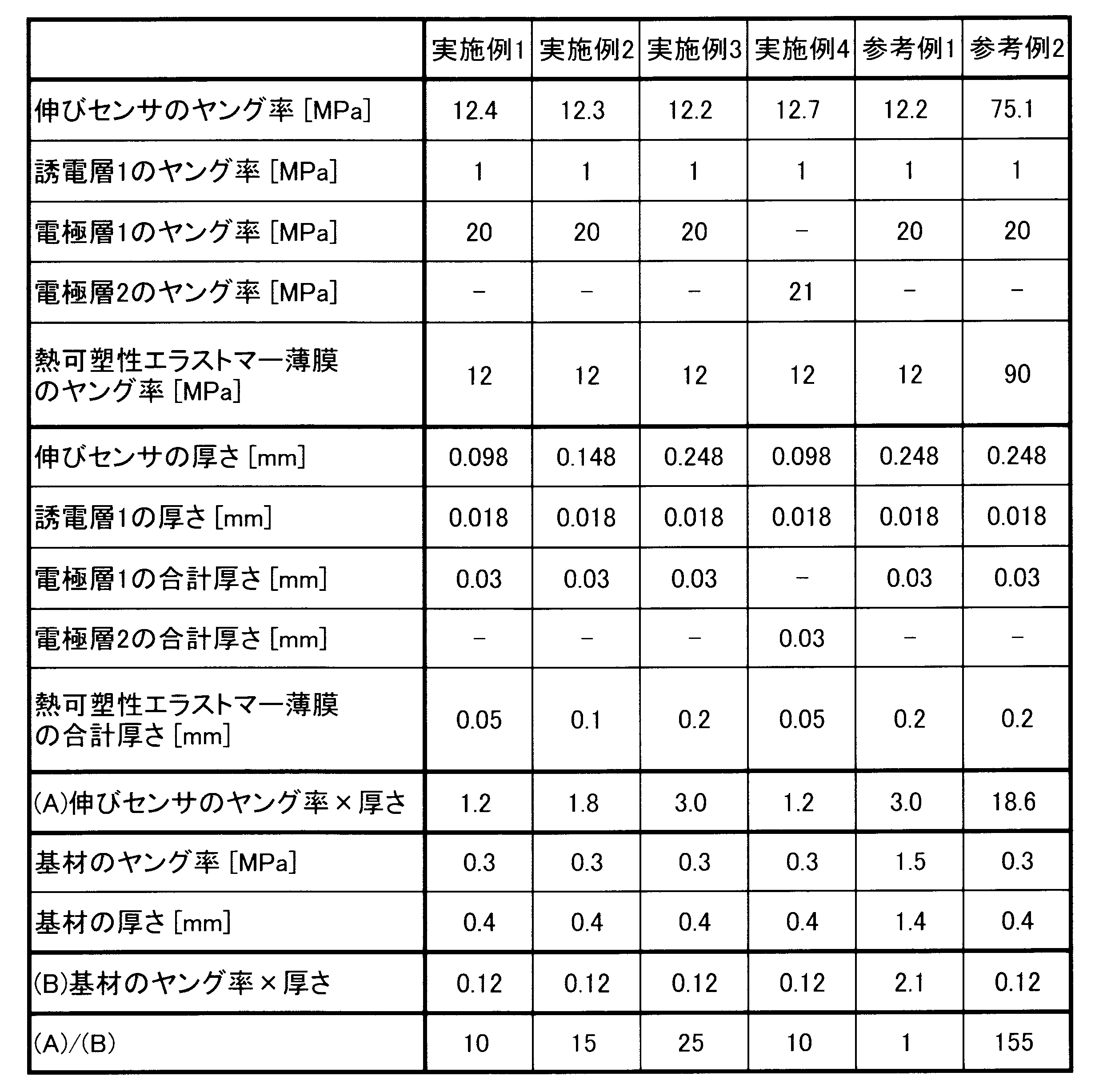
- Table 2 summarizes the specifications of the elongation sensor and the base material in each capacitance type elongation sensor system.
- FIG. 3 the rear direction of the expansion and contraction direction of the base material was set as the A direction, and the right direction was set as the B direction.
- the direction A corresponds to the short direction of the extension sensor, and the direction B corresponds to the longitudinal direction of the extension sensor.
- FIG. 5 shows a change in capacitance with respect to the amount of elongation in the A direction.
- the capacitance was measured when the center of the right side of the base material was gripped and the base material was extended in the B direction.
- the base material was stretched, and when the elongation sensor was slightly deformed, the capacitance increased accordingly.
- the capacitance increased even in a region where the amount of elongation was small.
- the adhesive layer and the protective layer are hard (Young's modulus 90 MPa) and do not have elasticity and do not satisfy the following requirement (2), when the elongation sensor is expanded, Since it does not return to the state, continuous operation cannot be measured. Therefore, the elongation sensor system of Reference Example 2 is not suitable for use in measuring continuous movement of a living body.
- the length of the sensor element in the longitudinal direction (B direction) is at least 5 times the length in the lateral direction (A direction).
- the Young's modulus of the elongation sensor is 20 MPa or less.
- the Young's modulus of the elongation sensor is E 1 (MPa)
- the thickness is T 1 (mm)
- the Young's modulus of the substrate is E 2 (MPa)
- the thickness is T 2 (mm)
- the value of 1 ⁇ T 1 / (E 2 ⁇ T 2 ) (the value of (A) / (B) in Table 2) is 10 or more.
- the difference in flexibility between the base material and the elongation sensor and the fact that the elongation sensor is difficult to elongate in the lateral direction are used to increase the elongation. Only the amount of elongation of the sensor in the longitudinal direction can be selectively detected. Therefore, according to the elongation sensor systems of Examples 1 to 4, by setting the direction in which the elongation is to be measured to the longitudinal direction (B direction) of the elongation sensor, the elongation in the direction to be measured can be accurately measured. .
- the capacitance-type stretch sensor system of the present invention is suitable for measurement of biological information such as respiratory status and heart rate, and measurement of various actions such as bending and stretching of a joint and holding and opening a hand.
- biological information such as respiratory status and heart rate
- various actions such as bending and stretching of a joint and holding and opening a hand.
- the capacitance type stretch sensor system of the present invention is useful in medical, nursing, health care, training, and other fields.
- Capacitance type elongation sensor sensor system 2: elongation sensor, 3: base material, 4: control device, 20: sensor element, 21: adhesive layer, 22: protective layer, 40, 41: wiring, 42: connector , 200: dielectric layer, 201, 202: electrode layer
Landscapes
- Physics & Mathematics (AREA)
- General Physics & Mathematics (AREA)
- Measurement Of Length, Angles, Or The Like Using Electric Or Magnetic Means (AREA)
Abstract
静電容量型伸びセンサシステム(1)は、伸縮性を有する基材(3)と、基材(3)に配置される伸びセンサ(2)と、を備える。伸びセンサ(2)は、エラストマーを有する誘電層(200)と、誘電層(200)を挟んで配置される複数の電極層(201、202)と、を有するセンサ素子(20)を備え、測定周波数が0.1Hz以上10kHz以下の範囲において、誘電層(200)の最大比誘電率は最小比誘電率の10倍以下である。
Description
本発明は、伸縮性を有する基材と柔軟なセンサ素子とを備える静電容量型伸びセンサシステムに関する。
例えば特許文献1に記載されているように、静電容量型センサを生体または衣服などに貼り付けて、呼吸数や関節の曲げ伸ばしなどの生体の動きを測定している。次式(a)で表されるように、静電容量型センサにおいては、伸張されて誘電層の厚さが小さくなり電極層間距離が小さくなると、静電容量が大きくなる。同時に、電極層の面積が大きくなると、静電容量が大きくなる。静電容量型センサによると、センサの伸縮による静電容量の変化に基づいて、生体の動きを測定することができる。
C=ε0εrS/d ・・・(a)
[C:静電容量、ε0:真空の誘電率、εr:誘電層の比誘電率、S:電極層の面積、d:電極層間距離]
C=ε0εrS/d ・・・(a)
[C:静電容量、ε0:真空の誘電率、εr:誘電層の比誘電率、S:電極層の面積、d:電極層間距離]
静電容量型センサの静電容量は、電極間に交流電圧を印加して測定される。生体の素早い動きを測定するためには、測定周波数を高くする方がよい。しかし、測定周波数を高くすると、漏れ電流が大きくなるため、消費電力が大きくなり経済的ではない。消費電力が大きいと、バッテリーで駆動させる場合にバッテリーの消耗が速くなり使い勝手が悪い。反対に、測定周波数を低くすると、消費電力は小さくなるが、生体の素早い動きを測定しにくくなる。したがって、測定したい動きに応じて、測定周波数を変更することが望ましい。
特許文献1~3に記載されているように、静電容量型センサを柔軟にするという観点から、誘電層にはエラストマーが使用される。この場合、測定周波数が変わると、誘電層の誘電率が変わってしまうことが問題になる。誘電層の誘電率は、電子分極、配向分極、イオン分極などの分極構造に影響を受ける。通常エラストマーには、架橋剤、架橋促進剤、分散剤などの多くの添加剤が配合される。これらの残渣が電界によりイオン化すると、当該イオンが反転して分極が発生する(イオン分極)。すなわち、誘電層にイオン成分が存在すると、イオン分極により多くの電荷が発生し誘電率が大きくなる。しかし、イオン分極には、イオン自体の反転が必要であるため、周波数が高くなると、イオンの反転する速度が周波数に追いつかなくなる。よって、低周波数領域ではイオン分極による誘電率の上昇が大きくなるのに対して、高周波数領域では誘電率の上昇はほとんど見られない。したがって、誘電層にイオン成分が含まれると、特に100Hz以下の低周波数領域でイオン分極による影響が大きくなることから、測定周波数の高低による誘電率の変化が顕著になる。先の式(a)に示されるように、誘電層の誘電率が変化すると、静電容量が変化するため、センサの感度が大きく変わってしまう。したがって、誘電層にエラストマーを用いる場合、測定したい動きに応じて測定周波数を変えることは難しい。また、EMC(電磁環境両立性)の観点から、電磁波ノイズを減らすために測定周波数を変更する必要がある場合には、静電容量の測定回路の部品を変更するなどの対策が必要になる。
本発明は、このような実情に鑑みてなされたものであり、エラストマーを含んでいても、測定周波数による比誘電率の変化が小さい誘電層を有するセンサ素子を備え、生体の動きなどを測定可能な静電容量型伸びセンサシステムを提供することを課題とする。
本発明の静電容量型伸びセンサシステムは、伸縮性を有する基材と、該基材に配置される伸びセンサと、を備える静電容量型伸びセンサシステムであって、該伸びセンサは、エラストマーを有する誘電層と、該誘電層を挟んで配置される複数の電極層と、を有するセンサ素子を備え、測定周波数が0.1Hz以上10kHz以下の範囲において、該誘電層の最大比誘電率は最小比誘電率の10倍以下であることを特徴とする。
本発明の静電容量型伸びセンサシステムを構成するセンサ素子は、エラストマーを有し、かつ、測定周波数が0.1Hz以上10kHz以下の範囲における比誘電率の変化が小さい誘電層を備える。例えば、生体の動きを測定するために使用される測定周波数は、1Hz~100Hz程度が適当である。本発明におけるセンサ素子によると、誘電層の比誘電率が当該周波数を含む範囲において変化しにくいため、生体の動きに応じて測定周波数を変更しても、静電容量が変化しにくい。したがって、測定回路の部品を変更することなく測定したい動きに最適な測定周波数を設定することができ、生体の様々な動きを精度良く測定することができる。また、ノイズを減らしたい周波数を避けて測定周波数を設定することにより、EMC規制にも対応しやすい。すなわち、測定周波数を変更しやすいことは、ノイズ対策にも有効である。
本発明の静電容量型伸びセンサシステムによると、伸びセンサは伸縮性を有する基材に配置される。例えば、基材がサポーターなどの場合にはそれを装着するだけで、あるいは基材が衣服の場合は着るだけで、容易に体の動きを測定することができる。
なお、比誘電率は測定周波数が低くなるにつれて大きくなる傾向にある。したがって、測定周波数が0.1Hzの時の比誘電率が、10kHz(10000Hz)の時の比誘電率に対して10倍以下であれば、「測定周波数が0.1Hz以上10kHz以下の範囲において、誘電層の最大比誘電率は最小比誘電率の10倍以下である」という要件を満足するといってよい。
以下、本発明の静電容量型伸びセンサシステムの実施の形態について説明する。まず、図面を参照しながら本発明の静電容量型伸びセンサシステムの一形態を説明する。図1に、本実施形態の静電容量型伸びセンサシステムの上面図を示す。図2に、図1のII-II断面図を示す。図2においては、上下方向が伸びセンサの厚さ方向に対応している。図1、図2に示すように、静電容量型伸びセンサシステム1は、伸びセンサ2と、基材3と、制御装置4と、を備えている。本実施形態においては、基材3の左右方向を測定方向、前後方向を測定方向に垂直な垂直方向と定義する。
基材3は、コンプレッションウエア(弾性繊維を使用した布)であり、伸縮性を有している。伸びセンサ2は、基材3の上面に左右方向に帯状に延在して配置されている。伸びセンサ2のヤング率は、20MPa以下である。伸びセンサ2の「ヤング率×厚さ」の値は、基材3の「ヤング率×厚さ」の値の10倍以上である。伸びセンサ2は、センサ素子20と、接着層21と、保護層22と、を備えている。
センサ素子20は、長方形薄膜状を呈している。センサ素子20の長辺の長さ(左右方向長さ)は短辺の長さ(前後方向長さ)の5倍以上である。センサ素子20は、誘電層200と、一対の電極層201、202と、を備えている。
誘電層200は、カルボキシル基変性水素化ニトリルゴムのポリマーが金属アルコキシド化合物のテトラキス(2-エチルヘキシルオキシ)チタンで架橋された架橋物からなる。当該架橋物は、本発明におけるエラストマーの概念に含まれる。誘電層200の比誘電率は13(測定周波数100Hz)であり、測定周波数が0.1Hz以上10kHz以下の範囲における最大比誘電率は最小比誘電率の10倍以下である。
電極層201、202は、いずれもアクリルゴムのポリマーが金属アルコキシド化合物のテトラキス(2-エチルヘキシルオキシ)チタンで架橋された架橋物と薄層黒鉛とを有している。当該架橋物は、本発明におけるエラストマーの概念に含まれる。電極層201は、誘電層200の上面に配置されている。電極層201の左端には、配線40が接続されている。電極層202は、誘電層200の下面に配置されている。電極層202の左端には、配線41が接続されている。
接着層21は、基材3とセンサ素子20との間に配置されている。接着層21は、軟化点が100℃程度のウレタン系熱可塑性エラストマーからなる。接着層21により、基材3とセンサ素子20とが接着されている。接着層21のヤング率は50MPa以下、破断伸びは10%以上である。
保護層22は、センサ素子20を被覆するように配置され、伸びセンサ2の最外層を形成している。保護層22は、接着層21と同じウレタン系熱可塑性エラストマーからなる。
制御装置4は、バッテリーと、静電容量検出部と、を備えている。バッテリーは、配線40、41を介して、電極層201、202間に交流電圧を印加する。静電容量検出部は、流れる電流の振り幅と電圧に対する位相差に基づいて、静電容量を検出する。
例えば、基材3が人の体の動きに伴い伸張すると、伸びセンサ2も基材3と共に伸張する。すると、誘電層200が伸張されて電極層201、202間の距離が小さくなると共に、電極層201、202の面積が大きくなる。これにより、センサ素子20の静電容量は大きくなる。制御装置4には、静電容量の変化とセンサ素子20の伸び量との関係を示すマップが予め格納されている。したがって、伸張前後の静電容量の変化量から、センサ素子20の伸び量、すなわち測定部位の伸び量が算出される。
本実施形態のセンサ素子20は、測定周波数が0.1Hz以上10kHz以下の範囲における比誘電率の変化が小さい誘電層200を備えている。よって、測定周波数を変更しても、静電容量が変化しにくい。したがって、制御装置4の部品を変更することなく、測定したい動きに最適な測定周波数を設定することができ、生体の様々な動きを精度良く測定することができる。また、測定周波数を変更しやすいため、ノイズ対策にも有効である。
本実施形態の基材3は、コンプレッションウエアである。よって、コンプレッションウエアを着るだけで、容易に体の動きを測定することができる。ここで、センサ素子20は、長辺と短辺との比(アスペクト比)が5倍以上の長方形状を呈している。詳細は後述するが、センサ素子20の長辺を伸びの測定方向に一致させ、基材3に対する伸びセンサ2の柔軟性を所定の範囲にすることで、測定方向においては伸びセンサ2と基材3とが一緒に伸張し、垂直方向においては主に基材3のみが伸張する。こうすることにより、測定方向における伸び量を選択的に、かつ体の動きを阻害することなく測定することができる。
本実施形態の伸びセンサ2は、接着層21により基材3に接着されている。接着層21は必須の構成要素ではないが、柔軟かつ加熱圧着可能な熱可塑性エラストマーを用いることにより、伸びセンサ2の柔軟性を維持しつつ、基材3への伸びセンサ2の固定が容易になる。また、伸びセンサ2の最外層は、保護層22からなる。保護層22は必須の構成要素ではないが、保護層22を配置することにより、伸びセンサ2に絶縁性、耐湿性、耐久性など様々な機能を付与することができる。
本発明の静電容量型伸びセンサシステムは上記形態に限定されるものではなく、本発明の要旨を逸脱しない範囲において、当業者が行い得る変更、改良などを施した種々の形態にて実施することができる。次に、本発明の静電容量型伸びセンサシステムを構成する個々の部材について説明する。
<基材>
基材は、伸縮性を有すればその種類は特に限定されない。例えば、布、ポリマーシート、布とポリマーとを組み合わせた生地などが挙げられる。布は、弾性繊維などの合成繊維や天然繊維を用いた織物、編物、不織布のいずれでもよい。ポリマーとしては、エラストマーやその発泡体が好適である。布とポリマーとの組合せは、布とポリマーシートとを積層した積層体、布にポリマー溶液を塗布したり、布をポリマー溶液に浸漬するなどしてコーティング処理したものが挙げられる。生体の動きに追従できるという観点から、基材は、10%以上伸張できるものが望ましい。例えば、基材としてサポーター、コンプレッションウエアなどを選択すれば、それらを身につけるだけで簡単に生体の動きを測定することができる。
基材は、伸縮性を有すればその種類は特に限定されない。例えば、布、ポリマーシート、布とポリマーとを組み合わせた生地などが挙げられる。布は、弾性繊維などの合成繊維や天然繊維を用いた織物、編物、不織布のいずれでもよい。ポリマーとしては、エラストマーやその発泡体が好適である。布とポリマーとの組合せは、布とポリマーシートとを積層した積層体、布にポリマー溶液を塗布したり、布をポリマー溶液に浸漬するなどしてコーティング処理したものが挙げられる。生体の動きに追従できるという観点から、基材は、10%以上伸張できるものが望ましい。例えば、基材としてサポーター、コンプレッションウエアなどを選択すれば、それらを身につけるだけで簡単に生体の動きを測定することができる。
<伸びセンサ>
伸びセンサは、エラストマーを有する誘電層と、該誘電層を挟んで配置される複数の電極層と、を有するセンサ素子を備える。
伸びセンサは、エラストマーを有する誘電層と、該誘電層を挟んで配置される複数の電極層と、を有するセンサ素子を備える。
[センサ素子]
(1)誘電層
誘電層はエラストマーを有する。エラストマーには、架橋ゴムおよび熱可塑性エラストマーが含まれ、これらの一種を単独で、または二種以上を組み合わせて用いることができる。エラストマーとしては、静電容量を大きくして測定感度を向上させるという観点から、比誘電率が大きいものが望ましい。具体的には、比誘電率が10以上(測定周波数100Hz)のものが好適である。比誘電率が大きいエラストマーとしては、例えば、ニトリルゴム(NBR)、水素化ニトリルゴム(H-NBR)、アクリルゴム、天然ゴム、イソプレンゴム、エチレン-酢酸ビニル共重合体、エチレン-酢酸ビニル-アクリル酸エステル共重合体、ブチルゴム、スチレン-ブタジエンゴム(SBR)、フッ素ゴム、エピクロルヒドリンゴム、クロロプレンゴム、塩素化ポリエチレン、クロロスルホン化ポリエチレンなどが挙げられる。また、官能基を導入するなどして変性されたエラストマーを用いてもよい。変性エラストマーとしては、例えば、カルボキシル基変性ニトリルゴム(X-NBR)、カルボキシル基変性水素化ニトリルゴム(XH-NBR)などが挙げられる。熱可塑性エラストマーは、架橋剤を使用しないため、不純物が入りにくい。熱可塑性エラストマーとしては、スチレン系(SBS、SEBS、SEPS)、オレフィン系(TPO)、塩ビ系(TPVC)、ウレタン系(TPU)、エステル系(TPEE)、アミド系(TPAE)、およびこれらの共重合体やブレンド体が挙げられる。なかでも、耐久性に優れる、比誘電率が大きいという理由から、ニトリルゴム、水素化ニトリルゴムが好適であり、後述する金属アルコキシド化合物と反応して架橋できるという理由から、カルボキシル基変性ニトリルゴム、カルボキシル基変性水素化ニトリルゴムが好適である。
(1)誘電層
誘電層はエラストマーを有する。エラストマーには、架橋ゴムおよび熱可塑性エラストマーが含まれ、これらの一種を単独で、または二種以上を組み合わせて用いることができる。エラストマーとしては、静電容量を大きくして測定感度を向上させるという観点から、比誘電率が大きいものが望ましい。具体的には、比誘電率が10以上(測定周波数100Hz)のものが好適である。比誘電率が大きいエラストマーとしては、例えば、ニトリルゴム(NBR)、水素化ニトリルゴム(H-NBR)、アクリルゴム、天然ゴム、イソプレンゴム、エチレン-酢酸ビニル共重合体、エチレン-酢酸ビニル-アクリル酸エステル共重合体、ブチルゴム、スチレン-ブタジエンゴム(SBR)、フッ素ゴム、エピクロルヒドリンゴム、クロロプレンゴム、塩素化ポリエチレン、クロロスルホン化ポリエチレンなどが挙げられる。また、官能基を導入するなどして変性されたエラストマーを用いてもよい。変性エラストマーとしては、例えば、カルボキシル基変性ニトリルゴム(X-NBR)、カルボキシル基変性水素化ニトリルゴム(XH-NBR)などが挙げられる。熱可塑性エラストマーは、架橋剤を使用しないため、不純物が入りにくい。熱可塑性エラストマーとしては、スチレン系(SBS、SEBS、SEPS)、オレフィン系(TPO)、塩ビ系(TPVC)、ウレタン系(TPU)、エステル系(TPEE)、アミド系(TPAE)、およびこれらの共重合体やブレンド体が挙げられる。なかでも、耐久性に優れる、比誘電率が大きいという理由から、ニトリルゴム、水素化ニトリルゴムが好適であり、後述する金属アルコキシド化合物と反応して架橋できるという理由から、カルボキシル基変性ニトリルゴム、カルボキシル基変性水素化ニトリルゴムが好適である。
測定周波数が0.1Hz以上10kHz以下の範囲において、誘電層の最大比誘電率は最小比誘電率の10倍以下である。8倍以下、さらには5倍以下であるとより好適である。測定周波数により比誘電率が変化しにくい誘電層を実現するには、できるだけ誘電層に含まれる不純物やイオン成分を少なくすることが望ましい。例えば、架橋剤として硫黄を用いると、架橋後のエラストマー中に、未反応の硫黄、加硫促進剤などに加えて、硫黄や加硫促進剤などの分解物が残存することが多い。これらの反応残渣は、イオン化してイオン分極を発生させる成分になる。したがって、誘電層に含まれるイオン成分を少なくするためには、架橋剤に金属アルコキシド化合物を用いることが望ましい。金属アルコキシド化合物としては、テトラ-n-ブトキシチタン、テトラ-n-ブトキシジルコニウム、テトラ-n-ブトキシシラン、アセトアルコキシアルミニウムジイソプロピレート、テトラ-i-プロポキシチタン、テトラエトキシシラン、テトラキス(2-エチルヘキシルオキシ)チタン、チタンブトキシドダイマーなどが挙げられる。
また、誘電層の比誘電率を大きくするという観点から、エラストマーに誘電性物質を加えるとよい。誘電性物質としては、誘電性粒子、半導体などが好適である。
エラストマーに誘電性粒子を加える場合、予め洗浄するなどして誘電性粒子から不純物やイオン成分を除去しておくことが望ましい。すなわち、エラストマーのポリマー溶液に、洗浄済みの誘電性粒子の粉末を配合した分散液を用いて、誘電層を形成すればよい。誘電性粒子を洗浄する場合、洗浄液としては、アセチルアセトンなどの金属錯体を形成する液などを用いればよい。金属錯体を形成する液を用いると、金属酸化物中の不純物を容易に除去することができる。誘電性粒子としては、チタン酸バリウム、ニオブ酸カリウム、ニオブ酸カリウムナトリウム、ニオブ酸カリウムナトリウムリチウム、チタン酸ジルコン酸鉛、ランタンドープチタン酸ジルコン酸鉛、チタン酸ストロンチウム、チタン酸ビスマス、チタン酸ビスマスバリウムなどの無機粒子が好適である。
エラストマーに半導体を加えると、高い電気抵抗を維持したまま比誘電率を大きくすることができる。半導体には、後述する無機半導体と、ポリアニリン、ポリチオフェンなどの有機半導体とがあるが、キャリア濃度を高くする、不純物が入りにくいという観点から、無機半導体の粒子が好適である。
無機半導体の粒子としては、無機物からなるp型またはn型半導体の粒子を用いればよい。p型またはn型半導体は、真性半導体に所定の元素を微量ドーピングした材料、酸化物およびカルコゲナイドなどのp型またはn型を示す材料、のいずれでもよい。カルコゲナイドは、硫化物、セレン化物、およびテルル化物を含む。これらのうち、安定性および安全性の観点から、酸化物または硫化物、なかでも金属酸化物または金属硫化物が好適である。
p型を示す金属酸化物、金属硫化物としては、ニッケルを含む化合物、1価の銅を含む化合物、コバルトを含む化合物が挙げられる。具体的には、酸化ニッケル、酸化銅、コバルトとナトリウムとの複合酸化物(例えばNaxCoO4)などが挙げられる。
n型を示す金属酸化物としては、酸化亜鉛、酸化チタン、酸化ジルコニウム、酸化インジウム、酸化ビスマス、酸化バナジウム、酸化タンタル、酸化ニオブ、酸化タングステン、酸化スズ、酸化鉄、タンタル酸カリウム、チタン酸バリウム、チタン酸カルシウムおよびチタン酸ストロンチウムなどが挙げられる。金属硫化物としては、硫化カドミウム、硫化亜鉛、および硫化インジウムなどが挙げられる。
粒子内のキャリア濃度を増加して、比誘電率向上効果を高めるという観点から、金属酸化物および金属硫化物としては、元素が一部置換されたものや、所定の元素が微量ドーピングされたものが望ましい。なかでも、チタン酸バリウムにLa、Nb、Ta、Y、Ca、Mg、Mnがドーピングされたもの、酸化チタンにNb、Ta、Sb、P、Nがドーピングされたもの、酸化スズにP、Sb、Alがドーピングされたもの、酸化亜鉛にAl、Gaがドーピングされたもの、酸化インジウムにSnがドーピングされたものが、好適である。また、複数の元素がドーピングされたものを用いてもよい。また、還元アニーリングなどにより、酸素欠損を生成して、キャリア濃度を増加させてもよい。元素のドーピング量は、ドーピングする母粒子により最適値が異なるため、適宜決定すればよい。例えば、ドーピング量は、0.01mol%以上20mol%以下であることが望ましい。ドーピング量が0.01mol%未満の場合には、比誘電率向上効果が少なく、20mol%を超えると、かえって比誘電率が小さくなる。より好適には、0.5mol%以上10mol%以下である。
誘電性物質の含有量は、誘電層が所望の比誘電率、体積抵抗率、柔軟性などを有するように、適宜決定すればよい。例えば、誘電性物質の含有量を、エラストマー100質量部に対して、5質量部以上100質量部以下にするとよい。消費電力を小さくするという観点から、誘電層の体積抵抗率は、1010Ω・cm以上であることが望ましい。1012Ω・cm以上が好適である。生体の動きを阻害しにくいという観点から、誘電層の厚さは、1μm以上200μm以下、さらには100μm以下であることが望ましい。
(2)電極層
電極層の材質は特に限定されないが、電極層は誘電層の変形に追従できるよう柔軟であることが望ましい。例えば、オイル、エラストマーなどのバインダーに導電材を混合した導電性塗料から電極層を形成すればよい。あるいは、炭素繊維や金属繊維をメッシュ状に編んで電極層を形成してもよい。前者の導電性塗料を採用する場合、伸張しても電気抵抗が増加しにくい電極層を形成するという観点から、バインダーとしてエラストマーを用いることが望ましい。エラストマーとしては、シリコーンゴム、NBR、エチレン-プロピレン-ジエンゴム(EPDM)、天然ゴム、SBR、アクリルゴム、ウレタンゴム、エピクロロヒドリンゴム、クロロスルホン化ポリエチレン、塩素化ポリエチレンなどの架橋ゴム、およびスチレン系、オレフィン系、塩ビ系、ウレタン系、エステル系、アミド系などの熱可塑性エラストマーが挙げられる。また、エポキシ基変性アクリルゴム、カルボキシル基変性水素化ニトリルゴムなどのように、官能基を導入するなどして変性したエラストマーを用いてもよい。導電材としては、カーボンブラック、ケッチェンブラック、カーボンナノチューブ、薄層黒鉛などの炭素材料や、銀、金、銅、ニッケル、ロジウム、パラジウム、クロム、チタン、白金、鉄、およびこれらの合金などの金属粉末を使用すればよい。
電極層の材質は特に限定されないが、電極層は誘電層の変形に追従できるよう柔軟であることが望ましい。例えば、オイル、エラストマーなどのバインダーに導電材を混合した導電性塗料から電極層を形成すればよい。あるいは、炭素繊維や金属繊維をメッシュ状に編んで電極層を形成してもよい。前者の導電性塗料を採用する場合、伸張しても電気抵抗が増加しにくい電極層を形成するという観点から、バインダーとしてエラストマーを用いることが望ましい。エラストマーとしては、シリコーンゴム、NBR、エチレン-プロピレン-ジエンゴム(EPDM)、天然ゴム、SBR、アクリルゴム、ウレタンゴム、エピクロロヒドリンゴム、クロロスルホン化ポリエチレン、塩素化ポリエチレンなどの架橋ゴム、およびスチレン系、オレフィン系、塩ビ系、ウレタン系、エステル系、アミド系などの熱可塑性エラストマーが挙げられる。また、エポキシ基変性アクリルゴム、カルボキシル基変性水素化ニトリルゴムなどのように、官能基を導入するなどして変性したエラストマーを用いてもよい。導電材としては、カーボンブラック、ケッチェンブラック、カーボンナノチューブ、薄層黒鉛などの炭素材料や、銀、金、銅、ニッケル、ロジウム、パラジウム、クロム、チタン、白金、鉄、およびこれらの合金などの金属粉末を使用すればよい。
なかでも、導電材に薄層黒鉛を用いると、電極層の電気抵抗を小さくすることができるため、測定周波数が高周波数であっても静電容量が低下しにくい。また、電極層の長さを長くしても電気抵抗が増加しにくいため、センサ素子を帯状に長くすることもできる。さらに、電極層を薄くすることができるため、より柔軟にすることができる。薄層黒鉛は、予め層間剥離され薄層化された黒鉛である。グラフェンは、黒鉛(グラファイト)の1層分であり、炭素原子の六員環が平面状に連なった構造を有する。薄層黒鉛は、複数のグラフェンの積層体であり、薄層黒鉛におけるグラフェンの積層数は、黒鉛よりも少なく、数層~数百層であることが望ましい。
電極層は、バインダーおよび導電材に加えて、必要に応じて架橋剤、分散剤、補強剤、可塑剤、老化防止剤、着色剤などの添加剤を含んでいてもよい。イオン成分が誘電層に移動しないように、電極層においても不純物やイオン成分が少ないことが望ましい。このため、バインダーにエラストマーを用いる場合、電極層に含まれるイオン成分を少なくするという観点から、架橋剤には金属アルコキシド化合物を用いることが望ましい。金属アルコキシド化合物については、先の(1)において述べたとおりである。
<基材と伸びセンサとの関係>
前出の式(a)C=ε0εrS/dで表されるように、伸びセンサの静電容量は、電極層の面積に比例して変化する。例えば、生体の動作におけるある一方向の伸び量を測定したい場合、基材および伸びセンサの柔軟性が高く、生体の動作により電極層が面方向に伸張すると、測定したい一方向の面積変化ではなく、面全体の面積変化に基づいて静電容量が算出されるため、当該一方向の伸び量を正確に測定することができない。すなわち、測定したい一方向だけでなく他の方向の伸びも検出してしまうため、測定精度が低下する。これは、伸びセンサが柔軟であるが故に生じることであるから、例えば伸びセンサを硬くして変形しにくくすれば、電極層の面方向の伸張を抑制することはできる。しかし、伸びセンサの柔軟性を低下させると、生体の動きに追従しないばかりか、むしろ動きを阻害するおそれがある。これでは、伸び量を正確に測定することにはならない。
前出の式(a)C=ε0εrS/dで表されるように、伸びセンサの静電容量は、電極層の面積に比例して変化する。例えば、生体の動作におけるある一方向の伸び量を測定したい場合、基材および伸びセンサの柔軟性が高く、生体の動作により電極層が面方向に伸張すると、測定したい一方向の面積変化ではなく、面全体の面積変化に基づいて静電容量が算出されるため、当該一方向の伸び量を正確に測定することができない。すなわち、測定したい一方向だけでなく他の方向の伸びも検出してしまうため、測定精度が低下する。これは、伸びセンサが柔軟であるが故に生じることであるから、例えば伸びセンサを硬くして変形しにくくすれば、電極層の面方向の伸張を抑制することはできる。しかし、伸びセンサの柔軟性を低下させると、生体の動きに追従しないばかりか、むしろ動きを阻害するおそれがある。これでは、伸び量を正確に測定することにはならない。
この点、上記特許文献1に記載されているセンサ装置によると、センサ本体を異方性を有する布(一方向に伸びやすく、当該一方向に直交する方向には伸びにくい布)に一体化することにより、センサ本体の伸縮方向を布の易伸縮方向である一方向に規制して、センサ本体の伸び量と電極層の面積変化とを比例させている。しかし、一方向にしか伸びない布を用いると、布が伸びにくい方向(難伸縮方向)への生体の動きを阻害してしまうため、生体の動きを規制することなく一方向の伸び量を正確に測定するという課題を解消するには至らない。
そこで、本発明の好適な態様は、測定したい方向に合わせてセンサ素子のアスペクト比を規定すると共に、伸びセンサのヤング率を規定し、基材のヤング率との関係を規定した。すなわち、本発明の静電容量型伸びセンサシステムにおいて、基材が伸縮する方向のうちの一方向を測定方向、該測定方向に垂直な方向を垂直方向と定義した場合に、センサ素子における該測定方向の長さは該垂直方向の長さに対して5倍以上であり、伸びセンサのヤング率は20MPa以下であり、伸びセンサのヤング率をE1(MPa)、厚さをT1(mm)、基材のヤング率をE2(MPa)、厚さをT2(mm)とした場合に、次式(i)を満足することが望ましい。より好適には、次式(ii)を満足することが望ましい。
10≦(E1×T1)/(E2×T2) ・・・(i)
15≦(E1×T1)/(E2×T2) ・・・(ii)
本態様においては、センサ素子の長手方向を測定方向に一致させ、基材に対する伸びセンサの柔軟性を所定の範囲にすることで、測定方向においては伸びセンサと基材とが一緒に伸張するが、垂直方向においては主に基材のみが伸張する。すなわち、伸びセンサが伸張しないため、垂直方向の伸びを検出しないで済む。こうすることにより、測定方向における伸び量のみを、生体の動きを阻害することなく正確に測定することができる。
10≦(E1×T1)/(E2×T2) ・・・(i)
15≦(E1×T1)/(E2×T2) ・・・(ii)
本態様においては、センサ素子の長手方向を測定方向に一致させ、基材に対する伸びセンサの柔軟性を所定の範囲にすることで、測定方向においては伸びセンサと基材とが一緒に伸張するが、垂直方向においては主に基材のみが伸張する。すなわち、伸びセンサが伸張しないため、垂直方向の伸びを検出しないで済む。こうすることにより、測定方向における伸び量のみを、生体の動きを阻害することなく正確に測定することができる。
本明細書においては、JIS K 6251:2017に準拠した引張試験により得られた応力-歪み曲線において、5%伸びの応力をその時の歪みで除した値をヤング率とする。試験片は短冊状2号形を用い、引張速度は500mm/分とする。
基材に対する伸びセンサの配置形態は特に限定されない。例えば、センサ素子の電極層と基材とが接するように、センサ素子を基材に直接的に固定してもよい。あるいは、上記実施形態に示したように、センサ素子を接着剤、熱可塑性エラストマーシートなどにより基材に間接的に固定してもよい。すなわち、伸びセンサは、基材とセンサ素子との間に接着層などの別部材を有していてもよい。一方、上記実施形態に示したように、センサ素子を絶縁し、保護するという観点から、センサ素子の外側(基材とは反対側)にセンサ素子を覆うように保護層を配置してもよい。すなわち、伸びセンサは、最外層に保護層などの別部材を有していてもよい。
伸びセンサがセンサ素子以外の部材を有する場合、先の式(i)、(ii)における伸びセンサのヤング率は、後述する実施例に示すように、部材ごとのヤング率に当該部材が伸びセンサに占める厚さの割合を乗じたものを足し合わせて算出される。以下、接着層および保護層について説明する。
[接着層]
接着層の材質は、センサ素子の電極層と基材とを接着できれば特に限定されない。伸びセンサの柔軟性を低下させないという観点から、接着層としては熱可塑性エラストマーを用いることが望ましい。熱可塑性エラストマーの軟化点が低すぎると、環境耐久性に劣る。よって、例えば軟化点が60℃以上150℃以下の熱可塑性エラストマーを用いると、環境耐久性を満足しつつ、アイロンなどで加熱して圧着することにより容易にセンサ素子を基材に固定することができる。好適な熱可塑性エラストマーは、柔軟であるという観点から、エーテル系ウレタン、エステル系ウレタンなどが挙げられる。
接着層の材質は、センサ素子の電極層と基材とを接着できれば特に限定されない。伸びセンサの柔軟性を低下させないという観点から、接着層としては熱可塑性エラストマーを用いることが望ましい。熱可塑性エラストマーの軟化点が低すぎると、環境耐久性に劣る。よって、例えば軟化点が60℃以上150℃以下の熱可塑性エラストマーを用いると、環境耐久性を満足しつつ、アイロンなどで加熱して圧着することにより容易にセンサ素子を基材に固定することができる。好適な熱可塑性エラストマーは、柔軟であるという観点から、エーテル系ウレタン、エステル系ウレタンなどが挙げられる。
センサ素子の伸縮に追従し、伸びセンサの柔軟性を確保するという観点から、接着層のヤング率は50MPa以下、破断伸びは10%以上であることが望ましい。本明細書においては、JIS K 6251:2017に準拠した引張試験により測定された切断時伸びを破断伸びとする。試験片はダンベル状2号形を用い、引張速度は500mm/分とする。
[保護層]
保護層の材質は、絶縁性、耐湿性、耐久性などを考慮して適宜決定すればよい。伸びセンサの柔軟性を低下させないという観点から、保護層にも熱可塑性エラストマーを用いることが望ましい。保護層の材質は接着層のそれと同じでも異なっていてもよい。接着層と同様に、センサ素子の伸縮に追従し、伸びセンサの柔軟性を確保するという観点から、保護層のヤング率は50MPa以下、破断伸びは10%以上であることが望ましい。
保護層の材質は、絶縁性、耐湿性、耐久性などを考慮して適宜決定すればよい。伸びセンサの柔軟性を低下させないという観点から、保護層にも熱可塑性エラストマーを用いることが望ましい。保護層の材質は接着層のそれと同じでも異なっていてもよい。接着層と同様に、センサ素子の伸縮に追従し、伸びセンサの柔軟性を確保するという観点から、保護層のヤング率は50MPa以下、破断伸びは10%以上であることが望ましい。
<制御装置>
本発明の静電容量型伸びセンサシステムは、基材に配置された伸びセンサの他に、伸びセンサからの出力信号を処理するための制御装置や、測定結果を表示するための表示装置などを備えて構成すればよい。例えば、上記形態に示したように、バッテリー駆動にすると、有線で接続する煩わしさを解消することができるため、ウエアラブルな用途に好適である。なお、測定周波数を低くすると、バッテリーの消費電力を抑えて動作時間を増やすことができる。本発明におけるセンサ素子によると、低周波数領域でも誘電層の比誘電率が変化しにくいため、バッテリー駆動の場合に好適である。
本発明の静電容量型伸びセンサシステムは、基材に配置された伸びセンサの他に、伸びセンサからの出力信号を処理するための制御装置や、測定結果を表示するための表示装置などを備えて構成すればよい。例えば、上記形態に示したように、バッテリー駆動にすると、有線で接続する煩わしさを解消することができるため、ウエアラブルな用途に好適である。なお、測定周波数を低くすると、バッテリーの消費電力を抑えて動作時間を増やすことができる。本発明におけるセンサ素子によると、低周波数領域でも誘電層の比誘電率が変化しにくいため、バッテリー駆動の場合に好適である。
次に、実施例を挙げて本発明をより具体的に説明する。
(1)比誘電率の測定
材料が異なる七種類の誘電層を製造し、測定周波数0.1~10000Hzの範囲における比誘電率を測定した。
材料が異なる七種類の誘電層を製造し、測定周波数0.1~10000Hzの範囲における比誘電率を測定した。
<誘電層の製造>
[誘電層1]
まず、カルボキシル基変性水素化ニトリルゴム(XH-NBR)のポリマー(ランクセス社製「テルバン(登録商標)XT8889」)を、アセチルアセトンに溶解して、固形分濃度が12質量%のポリマー溶液を調製した。次に、調製したポリマー溶液100質量部に、架橋剤のテトラキス(2-エチルヘキシルオキシ)チタン(TOT)のアセチルアセトン溶液(濃度20質量%)を5質量部添加した。そして、当該ポリマー溶液をポリエチレンテレフタレート(PET)製の基板(以下同じ)上に塗布し、乾燥させた後、150℃で60分間加熱して、誘電層1を製造した。
[誘電層1]
まず、カルボキシル基変性水素化ニトリルゴム(XH-NBR)のポリマー(ランクセス社製「テルバン(登録商標)XT8889」)を、アセチルアセトンに溶解して、固形分濃度が12質量%のポリマー溶液を調製した。次に、調製したポリマー溶液100質量部に、架橋剤のテトラキス(2-エチルヘキシルオキシ)チタン(TOT)のアセチルアセトン溶液(濃度20質量%)を5質量部添加した。そして、当該ポリマー溶液をポリエチレンテレフタレート(PET)製の基板(以下同じ)上に塗布し、乾燥させた後、150℃で60分間加熱して、誘電層1を製造した。
[誘電層2]
まず、リン(P)をドーピングした酸化スズ(SnO2)粉末(三菱マテリアル(株)製「EPSP2」)をアセチルアセトンへ分散して、濃度12質量%の分散液を調製した。使用した粉末は、n型無機半導体粒子の粉末である。次に、誘電層1と同じポリマー溶液100質量部に、調製した分散液13質量部を混合して、混合液を調製した。続いて、調製した混合液に、架橋剤のテトラキス(2-エチルヘキシルオキシ)チタンのアセチルアセトン溶液(濃度20質量%)を5質量部添加した。そして、当該混合液を基板上に塗布し、乾燥させた後、150℃で60分間加熱して、誘電層2を製造した。
まず、リン(P)をドーピングした酸化スズ(SnO2)粉末(三菱マテリアル(株)製「EPSP2」)をアセチルアセトンへ分散して、濃度12質量%の分散液を調製した。使用した粉末は、n型無機半導体粒子の粉末である。次に、誘電層1と同じポリマー溶液100質量部に、調製した分散液13質量部を混合して、混合液を調製した。続いて、調製した混合液に、架橋剤のテトラキス(2-エチルヘキシルオキシ)チタンのアセチルアセトン溶液(濃度20質量%)を5質量部添加した。そして、当該混合液を基板上に塗布し、乾燥させた後、150℃で60分間加熱して、誘電層2を製造した。
[誘電層3]
まず、チタン酸バリウム粉末をアセチルアセトンに投入し、撹拌した後に24時間静置した。その後、粉末をろ別し、真空乾燥して、洗浄済みチタン酸バリウム粉末を製造した。洗浄済みチタン酸バリウム粉末は、誘電性粒子の概念に含まれる。次に、誘電層1と同じ架橋剤溶液が添加されたポリマー溶液に、洗浄済みチタン酸バリウム粉末を加えて、分散液を調製した。洗浄済みチタン酸バリウム粉末は、ポリマー溶液のポリマー分100質量部に対して80質量部になるように加えた。そして、当該分散液を基板上に塗布し、乾燥させた後、150℃で60分間加熱して、誘電層3を製造した。
まず、チタン酸バリウム粉末をアセチルアセトンに投入し、撹拌した後に24時間静置した。その後、粉末をろ別し、真空乾燥して、洗浄済みチタン酸バリウム粉末を製造した。洗浄済みチタン酸バリウム粉末は、誘電性粒子の概念に含まれる。次に、誘電層1と同じ架橋剤溶液が添加されたポリマー溶液に、洗浄済みチタン酸バリウム粉末を加えて、分散液を調製した。洗浄済みチタン酸バリウム粉末は、ポリマー溶液のポリマー分100質量部に対して80質量部になるように加えた。そして、当該分散液を基板上に塗布し、乾燥させた後、150℃で60分間加熱して、誘電層3を製造した。
[誘電層4]
まず、アンチモン(Sb)をドーピングした酸化スズ(SnO2)と酸化チタン(TiO2)とからなる粉末(石原産業(株)製「FT-1000」)をアセチルアセトンへ分散して、濃度12質量%の分散液を調製した。使用した粉末は、n型無機半導体粒子の粉末である。次に、誘電層1と同じポリマー溶液100質量部に、調製した分散液13質量部を混合して、混合液を調製した。続いて、調製した混合液に、架橋剤のテトラキス(2-エチルヘキシルオキシ)チタンのアセチルアセトン溶液(濃度20質量%)を5質量部添加した。そして、当該混合液を基板上に塗布し、乾燥させた後、150℃で60分間加熱して、誘電層4を製造した。
まず、アンチモン(Sb)をドーピングした酸化スズ(SnO2)と酸化チタン(TiO2)とからなる粉末(石原産業(株)製「FT-1000」)をアセチルアセトンへ分散して、濃度12質量%の分散液を調製した。使用した粉末は、n型無機半導体粒子の粉末である。次に、誘電層1と同じポリマー溶液100質量部に、調製した分散液13質量部を混合して、混合液を調製した。続いて、調製した混合液に、架橋剤のテトラキス(2-エチルヘキシルオキシ)チタンのアセチルアセトン溶液(濃度20質量%)を5質量部添加した。そして、当該混合液を基板上に塗布し、乾燥させた後、150℃で60分間加熱して、誘電層4を製造した。
[誘電層5]
まず、反応容器にポリカーボネートジオール(旭化成(株)製「デュラノ-ル(登録商標)T5650J」、分子量800)を30.0質量部入れ、攪拌しながら減圧脱水を2時間実施した。次に、反応容器内を窒素置換した。それから、反応容器内にヘキサメチレンジイソシアネート(旭化成(株)製「デュラネート(登録商標)D201)46.6質量部、および1,4-フェニレンジイソシアナート(東京化成工業(株)製)6.05質量部を滴下し、窒素気流下100℃にて4時間攪拌して、イソシアネート末端プレポリマーAを合成した。続いて、ポリカーボネートジオール(同上)20.0質量部と、合成したイソシアネート末端プレポリマーA18.6質量部と、トリエチレンジアミン0.01質量部と、を配合し、攪拌後に減圧脱泡してウレタン反応液を調製した。調製したウレタン反応液を基板上に塗布し、乾燥させた後、150℃で3時間加熱して、ウレタンゴムからなる誘電層5を製造した。
まず、反応容器にポリカーボネートジオール(旭化成(株)製「デュラノ-ル(登録商標)T5650J」、分子量800)を30.0質量部入れ、攪拌しながら減圧脱水を2時間実施した。次に、反応容器内を窒素置換した。それから、反応容器内にヘキサメチレンジイソシアネート(旭化成(株)製「デュラネート(登録商標)D201)46.6質量部、および1,4-フェニレンジイソシアナート(東京化成工業(株)製)6.05質量部を滴下し、窒素気流下100℃にて4時間攪拌して、イソシアネート末端プレポリマーAを合成した。続いて、ポリカーボネートジオール(同上)20.0質量部と、合成したイソシアネート末端プレポリマーA18.6質量部と、トリエチレンジアミン0.01質量部と、を配合し、攪拌後に減圧脱泡してウレタン反応液を調製した。調製したウレタン反応液を基板上に塗布し、乾燥させた後、150℃で3時間加熱して、ウレタンゴムからなる誘電層5を製造した。
[誘電層6]
チタン酸バリウム粉末を洗浄せずに用いた点以外は、誘電層3と同様にして、誘電層6を製造した。
チタン酸バリウム粉末を洗浄せずに用いた点以外は、誘電層3と同様にして、誘電層6を製造した。
[誘電層7]
カルボキシル基変性水素化ニトリルゴムのポリマー(同上)に、硫黄、シリカ(日本アエロジル(株)製「アエロジル(登録商標)380」)、可塑剤(トリクレジルフォスフェート)、および老化防止剤など(三新化学工業(株)「サンセラー(登録商標)CZ-G」および「サンセラー22C」、鶴見化学工業(株)製「サルファックス(登録商標)T10」、大内新興化学工業(株)製「ノクタイザー(登録商標)SS」)を加えて、ロールにて混練し、未加硫ゴムを製造した。この未加硫ゴムをプレス機にてシート状に成形して、誘電層7を製造した。
カルボキシル基変性水素化ニトリルゴムのポリマー(同上)に、硫黄、シリカ(日本アエロジル(株)製「アエロジル(登録商標)380」)、可塑剤(トリクレジルフォスフェート)、および老化防止剤など(三新化学工業(株)「サンセラー(登録商標)CZ-G」および「サンセラー22C」、鶴見化学工業(株)製「サルファックス(登録商標)T10」、大内新興化学工業(株)製「ノクタイザー(登録商標)SS」)を加えて、ロールにて混練し、未加硫ゴムを製造した。この未加硫ゴムをプレス機にてシート状に成形して、誘電層7を製造した。
<比誘電率の測定結果>
製造した誘電層1~7をサンプルホルダー(ソーラトロン社製、12962A型)に設置して、誘電率測定インターフェイス(同社製、1296型)、および周波数応答アナライザー(同社製、1255B型)を併用して、比誘電率を測定した。表1に、比誘電率の測定結果を示す。

表1に示すように、誘電層1~4によると、測定周波数が0.1Hzの時の比誘電率が、10000Hzの時の比誘電率に対して10倍以下であった。すなわち、誘電層1~4は、「測定周波数が0.1Hz以上10kHz以下の範囲において、誘電層の最大比誘電率は最小比誘電率の10倍以下である」という要件を満足するといえる。この点において、誘電層1~4は、本発明の実施例に相当する。これに対して、誘電層5~7によると、測定周波数が1~0.1Hzと低くなると比誘電率が急激に大きくなった。この点において、誘電層5~7は、本発明の比較例に相当する。
製造した誘電層1~7をサンプルホルダー(ソーラトロン社製、12962A型)に設置して、誘電率測定インターフェイス(同社製、1296型)、および周波数応答アナライザー(同社製、1255B型)を併用して、比誘電率を測定した。表1に、比誘電率の測定結果を示す。
上述したように、イオン成分は低周波数領域で分極に寄与し、誘電率を上げる効果を発揮する。よって、誘電層1~4において比誘電率の周波数依存性が小さい理由として、誘電層に含まれる不純物やイオン成分が少ないことが挙げられる。具体的には、誘電層1~4においては、架橋剤として、架橋残渣が出にくい金属アルコキシド化合物を使用した。誘電層2、4においては、誘電性物質として、イオン成分の少ないn型無機半導体粉末を配合した。誘電層3においては、誘電性物質として、洗浄してイオン成分を除去した誘電性粒子を配合した。配合した誘電性粒子の洗浄の有無のみが異なる誘電層3と誘電層6とを比較すれば、低周波数領域におけるイオン成分の影響は明らかである。なお、ウレタンゴムを用いた誘電層5、架橋剤として硫黄を使用した誘電層6においては、不純物やイオン成分が多いと考えられる。
誘電層2~4は、誘電性物質を含有する。このため、例えば測定周波数が100Hzの場合を比較してわかるように、他の誘電層より比誘電率が大きくなった。したがって、誘電層2~4を用いると、静電容量が大きく、感度の高い静電容量型センサを実現することができる。
表1には、各誘電層のヤング率と破断伸びの値も示している。誘電層1~4によると、破断伸びの値が大きいため、測定対象の動きを阻害することなく伸び量を測定することができる。
(2)静電容量の測定
比誘電率の測定で製造した誘電層1を用いて伸びセンサを構成し、それを基材に接着して静電容量型伸びセンサシステムを製造した。そして、一方向に基材を伸ばした時の静電容量の変化を測定した。
比誘電率の測定で製造した誘電層1を用いて伸びセンサを構成し、それを基材に接着して静電容量型伸びセンサシステムを製造した。そして、一方向に基材を伸ばした時の静電容量の変化を測定した。
<静電容量型伸びセンサシステムの製造>
[実施例1]
(1)電極層1
まず、導電材50質量部に分散剤18質量部および溶剤を添加して導電材分散液を調製した。次に、調製した導電材分散液を、湿式ジェットミル(吉田機械興業(株)製「ナノヴェイタ(登録商標)」)により粉砕処理した。パス運転により、粉砕処理を合計3回行った(3パス処理)。1パス目は、ストレート型ノズル(ノズル径170μm)、処理圧力90MPaで行い、2パス目以降は、クロス型ノズル(ノズル径170μm)、処理圧力130MPaで行った。それから、粉砕処理後の導電材分散液に、ポリマー82質量部を溶剤に溶解したポリマー溶液を添加、混合して液状組成物を調製した。得られた液状組成物をバーコート法によりPET製の基板上に厚さ狙い値15μmにて塗布し、150℃下で2時間加熱することにより塗膜を硬化させた。このようにして電極層1を製造した。電極層1の製造に使用した材料は以下のとおりである。
ポリマー:カルボキシル基変性水素化ニトリルゴム(ランクセス社製「テルバンXT8889」)
導電材:薄層黒鉛((株)アイテック「iGurafen-α」)
分散剤:高分子量ポリエステル酸アミドアミン塩(楠本化成(株)「ディスパロン(登録商標)DA7301」)
溶剤:アセチルアセトン
(2)伸びセンサ
まず、ウレタン系の熱可塑性エラストマー薄膜(日本マタイ(株)製「UH370」、厚さ25μm、破断伸び320%)に、製造した電極層を重ねて、真空プレスで接着させた。次に、電極層の上面に誘電層1を重ねて、真空プレスで接着させた。さらに、誘電層1の上面に製造した電極層を重ねて、真空プレスで接着させた。最後に、電極層の上面に熱可塑性エラストマー薄膜(同上)を重ねて、真空プレスで接着させた。このようにして、「熱可塑性エラストマー薄膜/電極層/誘電層1/電極層/熱可塑性エラストマー薄膜」からなる伸びセンサを製造した。
[実施例1]
(1)電極層1
まず、導電材50質量部に分散剤18質量部および溶剤を添加して導電材分散液を調製した。次に、調製した導電材分散液を、湿式ジェットミル(吉田機械興業(株)製「ナノヴェイタ(登録商標)」)により粉砕処理した。パス運転により、粉砕処理を合計3回行った(3パス処理)。1パス目は、ストレート型ノズル(ノズル径170μm)、処理圧力90MPaで行い、2パス目以降は、クロス型ノズル(ノズル径170μm)、処理圧力130MPaで行った。それから、粉砕処理後の導電材分散液に、ポリマー82質量部を溶剤に溶解したポリマー溶液を添加、混合して液状組成物を調製した。得られた液状組成物をバーコート法によりPET製の基板上に厚さ狙い値15μmにて塗布し、150℃下で2時間加熱することにより塗膜を硬化させた。このようにして電極層1を製造した。電極層1の製造に使用した材料は以下のとおりである。
ポリマー:カルボキシル基変性水素化ニトリルゴム(ランクセス社製「テルバンXT8889」)
導電材:薄層黒鉛((株)アイテック「iGurafen-α」)
分散剤:高分子量ポリエステル酸アミドアミン塩(楠本化成(株)「ディスパロン(登録商標)DA7301」)
溶剤:アセチルアセトン
(2)伸びセンサ
まず、ウレタン系の熱可塑性エラストマー薄膜(日本マタイ(株)製「UH370」、厚さ25μm、破断伸び320%)に、製造した電極層を重ねて、真空プレスで接着させた。次に、電極層の上面に誘電層1を重ねて、真空プレスで接着させた。さらに、誘電層1の上面に製造した電極層を重ねて、真空プレスで接着させた。最後に、電極層の上面に熱可塑性エラストマー薄膜(同上)を重ねて、真空プレスで接着させた。このようにして、「熱可塑性エラストマー薄膜/電極層/誘電層1/電極層/熱可塑性エラストマー薄膜」からなる伸びセンサを製造した。
(3)静電容量型伸びセンサシステム
製造した伸びセンサを、基材であるコンプレッションウェア(TESLA社製、オールシーズン長袖、厚さ0.4mm)の上面に配置して、上からアイロンで加熱して熱可塑性エラストマー薄膜を溶融することにより、伸びセンサと基材とを接着させた。それから、基材の上面端部にコネクタを取り付け、伸びセンサの電極層と図示しない制御装置とを、配線で電気的に接続した。このようにして、静電容量型伸びセンサシステムを製造した。図3に、基材に配置された伸びセンサの上面図を示す。図3においては、説明の便宜上、伸びセンサにハッチングを施して示す。図4に、同伸びセンサの前後方向の断面模式図を示す。図3、図4中、前出図1、図2と対応する部材については同じ符号で示す。
製造した伸びセンサを、基材であるコンプレッションウェア(TESLA社製、オールシーズン長袖、厚さ0.4mm)の上面に配置して、上からアイロンで加熱して熱可塑性エラストマー薄膜を溶融することにより、伸びセンサと基材とを接着させた。それから、基材の上面端部にコネクタを取り付け、伸びセンサの電極層と図示しない制御装置とを、配線で電気的に接続した。このようにして、静電容量型伸びセンサシステムを製造した。図3に、基材に配置された伸びセンサの上面図を示す。図3においては、説明の便宜上、伸びセンサにハッチングを施して示す。図4に、同伸びセンサの前後方向の断面模式図を示す。図3、図4中、前出図1、図2と対応する部材については同じ符号で示す。
図3、図4に示すように、伸びセンサ2は、基材3の上面に接着されている。伸びセンサ2は、センサ素子20と、接着層21と、保護層22と、を備えている。センサ素子20は、誘電層200と、一対の電極層201、202と、を備えている。誘電層200は、縦(前後方向長さ)10mm、横(左右方向長さ)60mm、厚さ98μmの長方形薄膜状を呈している。電極層201、202は、各々、縦8mm、横50mm、厚さ15μmの長方形薄膜状を呈している。誘電層200と電極層201、202とが厚さ方向に重なる感圧部の大きさは、縦8mm、横50mmである。接着層21は、熱可塑性エラストマー薄膜からなり、縦10mm、横60mm、厚さ25μmの長方形薄膜状を呈している。保護層22も同様に、熱可塑性エラストマー薄膜からなり、縦10mm、横60mm、厚さ25μmの長方形薄膜状を呈している。伸びセンサ2の左端には、コネクタ42が取り付けられている。コネクタ42を介して、伸びセンサ2の電極層201、202と、図示しない制御装置とが、配線で電気的に接続されている。
[実施例2]
センサ素子の両側に積層される接着層および保護層の厚さを各々2倍に変更した点以外は、実施例1と同様にして伸びセンサを製造した。具体的には、センサ素子の両側に、熱可塑性エラストマー薄膜を二枚ずつ配置した。
センサ素子の両側に積層される接着層および保護層の厚さを各々2倍に変更した点以外は、実施例1と同様にして伸びセンサを製造した。具体的には、センサ素子の両側に、熱可塑性エラストマー薄膜を二枚ずつ配置した。
[実施例3]
センサ素子の両側に積層される接着層および保護層の厚さを各々4倍に変更した点以外は、実施例1と同様にして伸びセンサを製造した。具体的には、センサ素子の両側に、熱可塑性エラストマー薄膜を四枚ずつ配置した。
センサ素子の両側に積層される接着層および保護層の厚さを各々4倍に変更した点以外は、実施例1と同様にして伸びセンサを製造した。具体的には、センサ素子の両側に、熱可塑性エラストマー薄膜を四枚ずつ配置した。
[実施例4]
電極層1に代えて電極層2を配置した点以外は、実施例1と同様にして伸びセンサを製造した。電極層2の製造方法は以下のとおりである。まず、カルボキシル基変性水素化ニトリルゴム(電極層1と同じ)100質量部をアセチルアセトンに溶解したポリマー溶液に、導電材としてのケッチェンブラック23質量部を加えて混練した。次に、混練物を三本ロールに五回繰り返し通して、スラリーを得た。そして、得られたスラリーに、架橋剤のテトラキス(2-エチルヘキシルオキシ)チタン5質量部を加えてエア攪拌機で混練した後、スラリーをバーコート法によりPET製の基板上に厚さ狙い値15μmにて塗布した。これを150℃下で1時間加熱し、塗膜を硬化させて電極層2を製造した。
電極層1に代えて電極層2を配置した点以外は、実施例1と同様にして伸びセンサを製造した。電極層2の製造方法は以下のとおりである。まず、カルボキシル基変性水素化ニトリルゴム(電極層1と同じ)100質量部をアセチルアセトンに溶解したポリマー溶液に、導電材としてのケッチェンブラック23質量部を加えて混練した。次に、混練物を三本ロールに五回繰り返し通して、スラリーを得た。そして、得られたスラリーに、架橋剤のテトラキス(2-エチルヘキシルオキシ)チタン5質量部を加えてエア攪拌機で混練した後、スラリーをバーコート法によりPET製の基板上に厚さ狙い値15μmにて塗布した。これを150℃下で1時間加熱し、塗膜を硬化させて電極層2を製造した。
[参考例1]
基材の種類を変更した点以外は、実施例3と同様にして静電容量型伸びセンサシステムを製造した。基材には、Darchen社製のトレーニングインナーの腰部ゴム部分(厚さ1.4mm)を使用した。
基材の種類を変更した点以外は、実施例3と同様にして静電容量型伸びセンサシステムを製造した。基材には、Darchen社製のトレーニングインナーの腰部ゴム部分(厚さ1.4mm)を使用した。
[参考例2]
熱可塑性エラストマー薄膜の種類を変更した点以外は、実施例3と同様にして伸びセンサを製造した。すなわち、接着層および保護層には、ポリアミド系の熱可塑性エラストマー薄膜(日本マタイ(株)製「NT140」、厚さ25μm、破断伸び300%)を使用した。
熱可塑性エラストマー薄膜の種類を変更した点以外は、実施例3と同様にして伸びセンサを製造した。すなわち、接着層および保護層には、ポリアミド系の熱可塑性エラストマー薄膜(日本マタイ(株)製「NT140」、厚さ25μm、破断伸び300%)を使用した。
表2に、各静電容量型伸びセンサシステムにおける伸びセンサ、基材の仕様をまとめて示す。
<静電容量の測定結果>
図3に示すように、基材の伸縮方向のうち後方向をA方向、右方向をB方向と設定した。A方向は伸びセンサの短手方向に一致し、B方向は伸びセンサの長手方向に一致する。まず、基材の後辺中央部を把持し、基材をA方向に伸ばした時の静電容量を測定した。図5に、A方向の伸び量に対する静電容量の変化を示す。次に、基材の右辺中央部を把持し、基材をB方向に伸ばした時の静電容量を測定した。図6に、B方向の伸び量に対する静電容量の変化を示す。なお、参考例2の伸びセンサシステムについては、伸びセンサが硬く(ヤング率75.1MPa>20MPa)、伸縮性に乏しかったため、伸び量に対する静電容量の測定は行わなかった。
図3に示すように、基材の伸縮方向のうち後方向をA方向、右方向をB方向と設定した。A方向は伸びセンサの短手方向に一致し、B方向は伸びセンサの長手方向に一致する。まず、基材の後辺中央部を把持し、基材をA方向に伸ばした時の静電容量を測定した。図5に、A方向の伸び量に対する静電容量の変化を示す。次に、基材の右辺中央部を把持し、基材をB方向に伸ばした時の静電容量を測定した。図6に、B方向の伸び量に対する静電容量の変化を示す。なお、参考例2の伸びセンサシステムについては、伸びセンサが硬く(ヤング率75.1MPa>20MPa)、伸縮性に乏しかったため、伸び量に対する静電容量の測定は行わなかった。
図6に示すように、伸びセンサの長手方向と同じB方向に基材を伸ばした場合には、静電容量の変化に、伸びセンサシステムの違いはほとんど現れなかった。これに対して、図5に示すように、伸びセンサの短手方向と同じA方向に基材を伸ばした場合には、静電容量の変化に、伸びセンサシステムの違いが顕著に現れた。以下の(1)~(3)の要件を満足する実施例1~4の伸びセンサシステムでは、基材に対して伸びセンサが硬いため、伸び量が小さい領域(20%以下)では、主に基材のみが変形し、伸びセンサはほとんど変形しない。このため、伸び量が小さい領域では、静電容量の値にほとんど変化が見られなかった。さらに基材を伸ばしていき、伸びセンサが若干変形するとその分だけ静電容量は大きくなった。一方、基材が硬く、以下の(3)の要件を満足しない参考例1の伸びセンサシステムでは、伸び量が小さい領域においても静電容量は増加した。また、接着層および保護層が硬く(ヤング率90MPa)伸縮性を有さず、以下の(2)の要件を満足しない参考例2の伸びセンサシステムにおいては、伸びセンサが伸張されると元の状態に戻らないため、連続した動作を測定することができない。よって、参考例2の伸びセンサシステムは、生体の連続した動作を測定する用途には適していない。
(1)センサ素子における長手方向(B方向)の長さは短手方向(A方向)の長さに対して5倍以上。
(2)伸びセンサのヤング率は20MPa以下。
(3)伸びセンサのヤング率をE1(MPa)、厚さをT1(mm)、基材のヤング率をE2(MPa)、厚さをT2(mm)とした場合、(E1×T1)/(E2×T2)の値(表2中、(A)/(B)の値)が10以上。
(1)センサ素子における長手方向(B方向)の長さは短手方向(A方向)の長さに対して5倍以上。
(2)伸びセンサのヤング率は20MPa以下。
(3)伸びセンサのヤング率をE1(MPa)、厚さをT1(mm)、基材のヤング率をE2(MPa)、厚さをT2(mm)とした場合、(E1×T1)/(E2×T2)の値(表2中、(A)/(B)の値)が10以上。
このように、(1)~(3)の要件を満足する場合には、基材と伸びセンサとの柔軟性の違いと、伸びセンサが短手方向に伸張しにくいことを利用して、伸びセンサの長手方向の伸び量のみを選択的に検出することが可能になる。したがって、実施例1~4の伸びセンサシステムによると、伸び量を測定したい方向を伸びセンサの長手方向(B方向)に設定することにより、測定したい方向の伸び量を正確に測定することができる。
本発明の静電容量型伸びセンサシステムは、呼吸状態や心拍数などの生体情報の測定、関節の曲げ伸ばしや手を握ったり開いたりするなどの各種動作の測定に好適である。本発明の静電容量型伸びセンサシステムは、医療、介護、健康管理、トレーニングなどの現場で有用である。
1:静電容量型伸びセンサセンサシステム、2:伸びセンサ、3:基材、4:制御装置、20:センサ素子、21:接着層、22:保護層、40、41:配線、42:コネクタ、200:誘電層、201、202:電極層
Claims (11)
- 伸縮性を有する基材と、該基材に配置される伸びセンサと、を備える静電容量型伸びセンサシステムであって、
該伸びセンサは、エラストマーを有する誘電層と、該誘電層を挟んで配置される複数の電極層と、を有するセンサ素子を備え、
測定周波数が0.1Hz以上10kHz以下の範囲において、該誘電層の最大比誘電率は最小比誘電率の10倍以下であることを特徴とする静電容量型伸びセンサシステム。 - 前記基材が伸縮する方向のうちの一方向を測定方向、該測定方向に垂直な方向を垂直方向と定義して、
前記センサ素子における該測定方向の長さは該垂直方向の長さに対して5倍以上であり、
前記伸びセンサのヤング率は20MPa以下であり、
該伸びセンサのヤング率をE1(MPa)、厚さをT1(mm)、該基材のヤング率をE2(MPa)、厚さをT2(mm)とした場合に、次式(i)を満足する請求項1に記載の静電容量型伸びセンサシステム。
10≦(E1×T1)/(E2×T2) ・・・(i) - 前記伸びセンサは、前記センサ素子と前記基材との間に配置される接着層を備える請求項1または請求項2に記載の静電容量型伸びセンサシステム。
- 前記接着層は、熱可塑性エラストマーを有する請求項3に記載の静電容量型伸びセンサシステム。
- 前記接着層のヤング率は50MPa以下、破断伸びは10%以上である請求項3または請求項4に記載の静電容量型伸びセンサシステム。
- 前記誘電層の前記エラストマーは、金属アルコキシド化合物で架橋されてなる請求項1ないし請求項5のいずれかに記載の静電容量型伸びセンサシステム。
- 前記誘電層の前記エラストマーは、ニトリルゴム、水素化ニトリルゴム、カルボキシル基変性ニトリルゴム、カルボキシル基変性水素化ニトリルゴムから選ばれる一種以上である請求項1ないし請求項6のいずれかに記載の静電容量型伸びセンサシステム。
- 前記電極層は、エラストマーおよび導電材を有する請求項1ないし請求項7のいずれかに記載の静電容量型伸びセンサシステム。
- 前記電極層の前記エラストマーは、金属アルコキシド化合物で架橋されてなる請求項8に記載の静電容量型伸びセンサシステム。
- 前記導電材は、薄層黒鉛を含む請求項8または請求項9に記載の静電容量型伸びセンサシステム。
- 前記基材は布である請求項1ないし請求項10のいずれかに記載の静電容量型伸びセンサシステム。
Applications Claiming Priority (2)
| Application Number | Priority Date | Filing Date | Title |
|---|---|---|---|
| JP2018-122813 | 2018-06-28 | ||
| JP2018122813A JP6666958B2 (ja) | 2018-06-28 | 2018-06-28 | 静電容量型伸びセンサシステム |
Publications (1)
| Publication Number | Publication Date |
|---|---|
| WO2020003685A1 true WO2020003685A1 (ja) | 2020-01-02 |
Family
ID=68986990
Family Applications (1)
| Application Number | Title | Priority Date | Filing Date |
|---|---|---|---|
| PCT/JP2019/015078 Ceased WO2020003685A1 (ja) | 2018-06-28 | 2019-04-05 | 静電容量型伸びセンサシステム |
Country Status (2)
| Country | Link |
|---|---|
| JP (1) | JP6666958B2 (ja) |
| WO (1) | WO2020003685A1 (ja) |
Cited By (1)
| Publication number | Priority date | Publication date | Assignee | Title |
|---|---|---|---|---|
| JP2023548702A (ja) * | 2020-11-03 | 2023-11-20 | 智能容電(北京)科技有限公司 | フレキシブル可変コンデンサ及びその製造方法 |
Families Citing this family (1)
| Publication number | Priority date | Publication date | Assignee | Title |
|---|---|---|---|---|
| JP2023023773A (ja) * | 2021-08-06 | 2023-02-16 | セーレン株式会社 | センサ用電極 |
Citations (5)
| Publication number | Priority date | Publication date | Assignee | Title |
|---|---|---|---|---|
| JPH0412403A (ja) * | 1990-04-27 | 1992-01-17 | Nissan Motor Co Ltd | 複合誘電体材料の製造方法 |
| JP2015059845A (ja) * | 2013-09-19 | 2015-03-30 | バンドー化学株式会社 | 静電容量型センサ、及び伸縮変形歪み量、伸縮変形歪み分布又は面圧分布の計測方法 |
| JP2015187931A (ja) * | 2014-03-26 | 2015-10-29 | 住友理工株式会社 | 誘電膜およびその製造方法、並びにそれを用いたトランスデューサ |
| JP2016501303A (ja) * | 2012-12-05 | 2016-01-18 | ダンマルクス テクニスケ ウニベルシテット | イオン性超分子構造を含む誘電性電場応答性高分子 |
| JP2016153729A (ja) * | 2015-02-20 | 2016-08-25 | 住友理工株式会社 | 変形量測定構造体 |
Family Cites Families (1)
| Publication number | Priority date | Publication date | Assignee | Title |
|---|---|---|---|---|
| JP2006340944A (ja) * | 2005-06-10 | 2006-12-21 | Hiroshima Univ | 大変形センサ及びこれを用いた座席者挙動検知センサ・監視装置、遊技・訓練装置 |
-
2018
- 2018-06-28 JP JP2018122813A patent/JP6666958B2/ja active Active
-
2019
- 2019-04-05 WO PCT/JP2019/015078 patent/WO2020003685A1/ja not_active Ceased
Patent Citations (5)
| Publication number | Priority date | Publication date | Assignee | Title |
|---|---|---|---|---|
| JPH0412403A (ja) * | 1990-04-27 | 1992-01-17 | Nissan Motor Co Ltd | 複合誘電体材料の製造方法 |
| JP2016501303A (ja) * | 2012-12-05 | 2016-01-18 | ダンマルクス テクニスケ ウニベルシテット | イオン性超分子構造を含む誘電性電場応答性高分子 |
| JP2015059845A (ja) * | 2013-09-19 | 2015-03-30 | バンドー化学株式会社 | 静電容量型センサ、及び伸縮変形歪み量、伸縮変形歪み分布又は面圧分布の計測方法 |
| JP2015187931A (ja) * | 2014-03-26 | 2015-10-29 | 住友理工株式会社 | 誘電膜およびその製造方法、並びにそれを用いたトランスデューサ |
| JP2016153729A (ja) * | 2015-02-20 | 2016-08-25 | 住友理工株式会社 | 変形量測定構造体 |
Non-Patent Citations (1)
| Title |
|---|
| TSUTSUNI, KAZUYUKI ET AL: "Distortion Measurement Method for Resin Foams for Sublimation Pattern Forging", 161ST MEETING OF THE JAPAN FOUNDRY ENGINEERING SOCIETY, 1 October 2012 (2012-10-01), pages 149 * |
Cited By (3)
| Publication number | Priority date | Publication date | Assignee | Title |
|---|---|---|---|---|
| JP2023548702A (ja) * | 2020-11-03 | 2023-11-20 | 智能容電(北京)科技有限公司 | フレキシブル可変コンデンサ及びその製造方法 |
| EP4243042A4 (en) * | 2020-11-03 | 2024-01-03 | Zhi Neng Rong Dian (Beijing) Technology Co., Ltd | FLEXIBLE VARIABLE CAPACITOR AND PRODUCTION METHOD THEREOF |
| US12542244B2 (en) | 2020-11-03 | 2026-02-03 | Zhi Neng Rong Dian (Beijing) Technology Co., Ltd | Flexible variable capacitor and method for preparation thereof |
Also Published As
| Publication number | Publication date |
|---|---|
| JP6666958B2 (ja) | 2020-03-18 |
| JP2020003332A (ja) | 2020-01-09 |
Similar Documents
| Publication | Publication Date | Title |
|---|---|---|
| JP5633769B1 (ja) | 柔軟なトランスデューサ | |
| JP6696885B2 (ja) | 圧電センサ | |
| TWI491862B (zh) | Electrostatic Capacitive Sensing Sheet, Electrostatic Capacitive Sensing Sheet Manufacturing Method and Sensor | |
| JP2016153729A (ja) | 変形量測定構造体 | |
| JP7060847B2 (ja) | 伸縮性コンデンサ、変形センサ、変位センサ、呼吸状態のセンシング方法およびセンシングウェア | |
| KR20170074914A (ko) | 정전 용량형 센서 | |
| CN112284239A (zh) | 静电电容型感测片的使用方法 | |
| US11737710B2 (en) | Piezoelectric sensor and method for manufacturing the same | |
| JP2017168438A (ja) | 伸縮性導体形成用ペースト、伸縮性導体シートおよび生体情報計測用プローブ | |
| KR20160053079A (ko) | 압전성 섬유사, 이의 제조방법 및 이를 이용한 직물, 의류 제품 및 피복형 압전 센서 | |
| JP6666958B2 (ja) | 静電容量型伸びセンサシステム | |
| EP3056547A1 (en) | Conductive material and transducer using same | |
| JP5290107B2 (ja) | 張力センサ | |
| WO2018159374A1 (ja) | 導電性ペーストおよびそれを用いた伸縮性配線、伸縮性配線を有する衣服型電子機器 | |
| WO2021065085A1 (ja) | 圧電センサおよび生体情報取得用衣服 | |
| JP2018059042A (ja) | 誘電エラストマー材料およびそれを用いたトランスデューサ | |
| WO2019044318A1 (ja) | 生体情報検出装置 | |
| WO2019150850A1 (ja) | トランスデューサおよびそれを用いた発電システム | |
| JP6996214B2 (ja) | 着用型生体情報計測装置および生体情報計測方法 | |
| WO2018061393A1 (ja) | 誘電エラストマー材料およびそれを用いたトランスデューサ | |
| JP5916270B2 (ja) | 誘電膜およびそれを用いたトランスデューサ | |
| KR102738675B1 (ko) | 에너지 저장이 가능한 플렉서블 전기변색소자를 구비하는 웨어러블 디바이스, 이의 제조 및 구동 방법 | |
| JP2021159221A (ja) | 無電源微弱電流デバイス |
Legal Events
| Date | Code | Title | Description |
|---|---|---|---|
| 121 | Ep: the epo has been informed by wipo that ep was designated in this application |
Ref document number: 19826993 Country of ref document: EP Kind code of ref document: A1 |
|
| NENP | Non-entry into the national phase |
Ref country code: DE |
|
| 122 | Ep: pct application non-entry in european phase |
Ref document number: 19826993 Country of ref document: EP Kind code of ref document: A1 |