WO2020003682A1 - 基地局、端末、受信方法及び送信方法 - Google Patents
基地局、端末、受信方法及び送信方法 Download PDFInfo
- Publication number
- WO2020003682A1 WO2020003682A1 PCT/JP2019/014990 JP2019014990W WO2020003682A1 WO 2020003682 A1 WO2020003682 A1 WO 2020003682A1 JP 2019014990 W JP2019014990 W JP 2019014990W WO 2020003682 A1 WO2020003682 A1 WO 2020003682A1
- Authority
- WO
- WIPO (PCT)
- Prior art keywords
- orthogonal
- signal
- access
- base station
- terminals
- Prior art date
- Legal status (The legal status is an assumption and is not a legal conclusion. Google has not performed a legal analysis and makes no representation as to the accuracy of the status listed.)
- Ceased
Links
Images









Classifications
-
- H—ELECTRICITY
- H04—ELECTRIC COMMUNICATION TECHNIQUE
- H04L—TRANSMISSION OF DIGITAL INFORMATION, e.g. TELEGRAPHIC COMMUNICATION
- H04L27/00—Modulated-carrier systems
- H04L27/26—Systems using multi-frequency codes
-
- H—ELECTRICITY
- H04—ELECTRIC COMMUNICATION TECHNIQUE
- H04L—TRANSMISSION OF DIGITAL INFORMATION, e.g. TELEGRAPHIC COMMUNICATION
- H04L27/00—Modulated-carrier systems
- H04L27/26—Systems using multi-frequency codes
- H04L27/2601—Multicarrier modulation systems
-
- H—ELECTRICITY
- H04—ELECTRIC COMMUNICATION TECHNIQUE
- H04J—MULTIPLEX COMMUNICATION
- H04J1/00—Frequency-division multiplex systems
-
- H—ELECTRICITY
- H04—ELECTRIC COMMUNICATION TECHNIQUE
- H04J—MULTIPLEX COMMUNICATION
- H04J11/00—Orthogonal multiplex systems, e.g. using WALSH codes
-
- H—ELECTRICITY
- H04—ELECTRIC COMMUNICATION TECHNIQUE
- H04J—MULTIPLEX COMMUNICATION
- H04J13/00—Code division multiplex systems
- H04J13/0003—Code application, i.e. aspects relating to how codes are applied to form multiplexed channels
-
- H—ELECTRICITY
- H04—ELECTRIC COMMUNICATION TECHNIQUE
- H04J—MULTIPLEX COMMUNICATION
- H04J13/00—Code division multiplex systems
- H04J13/0007—Code type
- H04J13/004—Orthogonal
-
- H—ELECTRICITY
- H04—ELECTRIC COMMUNICATION TECHNIQUE
- H04J—MULTIPLEX COMMUNICATION
- H04J99/00—Subject matter not provided for in other groups of this subclass
-
- H—ELECTRICITY
- H04—ELECTRIC COMMUNICATION TECHNIQUE
- H04L—TRANSMISSION OF DIGITAL INFORMATION, e.g. TELEGRAPHIC COMMUNICATION
- H04L1/00—Arrangements for detecting or preventing errors in the information received
- H04L1/02—Arrangements for detecting or preventing errors in the information received by diversity reception
-
- H—ELECTRICITY
- H04—ELECTRIC COMMUNICATION TECHNIQUE
- H04W—WIRELESS COMMUNICATION NETWORKS
- H04W4/00—Services specially adapted for wireless communication networks; Facilities therefor
- H04W4/70—Services for machine-to-machine communication [M2M] or machine type communication [MTC]
-
- H—ELECTRICITY
- H04—ELECTRIC COMMUNICATION TECHNIQUE
- H04J—MULTIPLEX COMMUNICATION
- H04J11/00—Orthogonal multiplex systems, e.g. using WALSH codes
- H04J2011/0003—Combination with other multiplexing techniques
- H04J2011/0006—Combination with other multiplexing techniques with CDM/CDMA
-
- H—ELECTRICITY
- H04—ELECTRIC COMMUNICATION TECHNIQUE
- H04W—WIRELESS COMMUNICATION NETWORKS
- H04W88/00—Devices specially adapted for wireless communication networks, e.g. terminals, base stations or access point devices
- H04W88/08—Access point devices
-
- Y—GENERAL TAGGING OF NEW TECHNOLOGICAL DEVELOPMENTS; GENERAL TAGGING OF CROSS-SECTIONAL TECHNOLOGIES SPANNING OVER SEVERAL SECTIONS OF THE IPC; TECHNICAL SUBJECTS COVERED BY FORMER USPC CROSS-REFERENCE ART COLLECTIONS [XRACs] AND DIGESTS
- Y02—TECHNOLOGIES OR APPLICATIONS FOR MITIGATION OR ADAPTATION AGAINST CLIMATE CHANGE
- Y02D—CLIMATE CHANGE MITIGATION TECHNOLOGIES IN INFORMATION AND COMMUNICATION TECHNOLOGIES [ICT], I.E. INFORMATION AND COMMUNICATION TECHNOLOGIES AIMING AT THE REDUCTION OF THEIR OWN ENERGY USE
- Y02D30/00—Reducing energy consumption in communication networks
- Y02D30/70—Reducing energy consumption in communication networks in wireless communication networks
Definitions
- the present disclosure relates to a base station, a terminal, a receiving method, and a transmitting method.
- MTC Machine Type Communication
- LTE Long Term Evolution
- LPWA Low Power Wide Area
- IoT Internet of Things
- NB-IoT Near @ Band @ IoT
- MTC and NB-IoT mainly support functions for realizing cost reduction, power saving, extension of coverage, and the like of a terminal (also referred to as UE: User @ Equipment) (for example, Non-Patent References 1-3).
- the MMTC massive MTC
- eMBB enhanced mobile broadband
- URLLC ultra-reliable low-latency communication
- 3GPP TS 36.211 “Evolved Universal Terrestrial Radio Access (E-UTRA); Physical channels and modulation (Release 14),” V14.3.0, June 2017.
- 3GPP TS 36.212 “Evolved Universal Terrestrial Radio Access (E-UTRA); Multiplexing and channel coding (Release 14),” V14.3.0, June 2017.
- 3GPP TS 36.213 “Evolved Universal Terrestrial Radio Access (E-UTRA); Physical layer procedure for control (Release 14),” V14.3.0, June 2017. RP-171043, “Revision of Study on 5G Non-orthogonal Multiple Access,” ZTE, RAN # 76, June 2017.
- R1-163993 “Non-orthogonal multiple access considerations for NR,” Samsung, RAN1 # 85, May 2016. K. Kusume, G. Bauch, and W. Utschick, IDIDMAIDvs. CDMA: Analysis and comparison of two multiple access schemes, IEEE Trans. Wireless Commun., Vol.11, No. 1, January 2012.
- R1-162517 “Considerations on DL / UL multiple access for NR,” LG Electronics, RAN1 # 84bis, April 2016.
- R1-165019 “Non-orthogonal multiple access for New Radio,” Nokia, Alcatel-Lucent Shanghai Bell, RAN1 # 85, May 2016.
- R1-167535 “New uplink non-orthogonal multiple access schemes for NR,” MediaTek, RAN1 # 86, August 2016.
- R1-164329 “Initial LLS results for UL for non-orthogonal multiple access,” Fujitsu, RAN1 # 85, May 2016.
- R1-162385 “Multiple access schemes for new radio interface,” Intel, RAN1 # 84bis, April 2016.
- the non-limiting embodiment of the present disclosure contributes to providing a base station, a terminal, a receiving method, and a transmitting method that can improve the frequency use efficiency in the uplink.
- a base station is a receiver that receives a transmission signal repeatedly transmitted over a plurality of allocation units, a non-orthogonal multi-access in which signals of a plurality of terminals are not orthogonal to each other, and a plurality of terminals.
- a terminal is based on a combination of non-orthogonal multi-access in which signals of a plurality of terminals are not orthogonal to each other and orthogonal multi-access in which signals of a plurality of terminals are orthogonal to each other, over a plurality of allocation units.
- the circuit includes a circuit that generates a transmission signal that is repeatedly transmitted, and a transmitter that transmits the transmission signal.
- the reception method receives a transmission signal repeatedly transmitted over a plurality of allocation units, non-orthogonal multi-access in which signals of a plurality of terminals are not orthogonal to each other, and signals of a plurality of terminals are mutually
- the transmission signal is demodulated based on a combination of orthogonal multiple access orthogonal.
- the transmission method is based on a combination of non-orthogonal multi-access in which signals of a plurality of terminals are not orthogonal to each other and orthogonal multi-access in which signals of a plurality of terminals are orthogonal to each other. To generate a transmission signal to be repeatedly transmitted, and transmit the transmission signal.
- FIG. 2 is a block diagram showing a configuration of a part of the base station according to Embodiment 1.
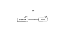
- FIG. 2 is a block diagram showing a partial configuration of a terminal according to Embodiment 1.
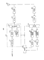
- FIG. 3 is a block diagram showing a configuration of a base station according to Embodiment 1.
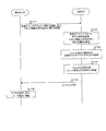
- FIG. 2 is a block diagram showing a configuration of a terminal according to Embodiment 1. Sequence diagram showing processing of a base station and a terminal according to Embodiment 1.
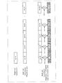
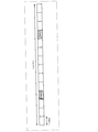
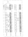
- FIG. 4 is a diagram showing an example of generation of a Repetition signal according to the first embodiment.
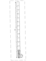
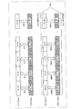
- FIG. 14 is a diagram showing another example of generation of the Repetition signal according to the first embodiment.
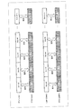
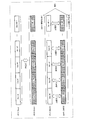
- FIG. 11 is a diagram illustrating an example of generating a Repetition signal according to Option # 1-3 of the second embodiment.
- FIG. 11 is a diagram illustrating an example of generating a Repetition signal according to Option # 1-3 of the second embodiment.
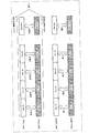
- FIG. 14 is a diagram illustrating an example of generating a Repetition signal according to Option # 2-3 according to the second embodiment.
- FIG. 14 is a diagram illustrating an example of generating a Repetition signal according to Option # 3-3 of the second embodiment.
- FIG. 14 is a diagram illustrating an example (two-stage processing) of user detection and demodulation processing according to Embodiment 3.
- FIG. 19 is a diagram showing another example (collective processing) of the user detection and demodulation processing according to the third embodiment.
- non-overload multiplex transmission is performed by transmitting more signals than the number of wireless resources in multi-access in order to improve the frequency utilization efficiency for mMTC.
- Orthogonal multiple access for example, NOMA: Non-Orthogonal @ Multiple @ Access
- NOMA Non-Orthogonal @ Multiple @ Access
- the LTE MTC and NB-IoT wireless interfaces support a repetition function as a coverage extension function.
- the same signal is repeatedly transmitted, and the reception side combines the signals to improve the received signal-to-noise power ratio (SNR) and extend the coverage.
- SNR signal-to-noise power ratio
- a plurality of radio resources for example, a plurality of slots or a plurality of subframes
- radio resource allocation within a single slot or a single subframe is assumed.
- Repetition supported as a basic function in LTE MTC and NB-IoT that is, radio resource allocation of multiple slots or multiple subframes is not assumed.
- the size of a signature for example, a spreading code or a codebook
- a signature for example, a spreading code or a codebook
- the size of the Signature increases, so that the amount of processing such as user detection or demodulation calculation processing on the receiving side may significantly increase.
- a case will be described where a maximum of U terminals are multiplexed using X radio resources (for example, resource elements (RE: Resource @ Element)) for non-orthogonal multiple access in the case of single slot allocation.
- X radio resources for example, resource elements (RE: Resource @ Element)
- the size of the factor graph matrix for performing MPA is X * XU.
- R Repetition in which the number of Repetitions (or Repetition size or Repetition Factor) is R, simply expanding radio resources for non-orthogonal multi-access by a plurality of slots, a factor graph for performing MPA
- the matrix size is R (X ⁇ U).
- the frequency utilization efficiency is reduced to 1 / R by Repetition
- the number of multiplexed terminals can be increased by R times, so that the number of multiplexed terminals per radio resource is U / X overall, Does not occur.
- the amount of arithmetic processing of the MPA increases exponentially as the number of multiplexed terminals increases.
- the communication system includes base station 100 and terminal 200.
- FIG. 1 is a block diagram showing a partial configuration of base station 100 according to the present embodiment.
- receiving section 112 receives a transmission signal repeatedly transmitted over a plurality of allocation units (for example, slots), and reception signal processing section 114 transmits signals from a plurality of terminals to each other.
- the transmission signal is demodulated based on a combination of non-orthogonal non-orthogonal multi-access and signals of a plurality of terminals that are orthogonal to each other.
- FIG. 2 is a block diagram showing a partial configuration of terminal 200 according to the present embodiment.
- signal generation section 210 performs multiple allocation units based on a combination of non-orthogonal multi-access in which signals of a plurality of terminals are not orthogonal to each other and orthogonal multi-access in which signals of a plurality of terminals are orthogonal to each other.
- the transmission unit 216 generates a transmission signal repeatedly transmitted over (for example, a slot), and the transmission unit 216 transmits the transmission signal.
- FIG. 3 is a block diagram showing a configuration of base station 100 according to Embodiment 1.
- base station 100 includes control section 101, higher control signal generation section 102, coding section 103, modulation section 104, downlink control signal generation section 105, coding section 106, and modulation section 107.
- IFFT Inverse Fast Fourier Transform
- the control unit 101 determines control information on uplink transmission of the terminal 200 and outputs the determined control information to the upper control signal generation unit 102, the downlink control signal generation unit 105, and the reception signal processing unit 114.
- the information on uplink transmission includes, for example, information on non-orthogonal multiple access, information on code sequences orthogonal to each other in a plurality of slots to which Repetition signals are allocated (hereinafter, referred to as an inter-slot orthogonal code sequence), information on Repetition, code
- the information includes information on the modulation / modulation scheme, information on the radio resource allocation, and the like.
- the information output to the higher control signal generation unit 102 includes, for example, information related to non-orthogonal multiple access, information related to an inter-slot orthogonal code sequence, and the like.
- the information output to the downlink control signal generation unit 105 includes, for example, information related to non-orthogonal multi-access, information related to an inter-slot orthogonal code sequence, or a transmission instruction by UL grant.
- Information related to uplink transmission for example, information indicating coding and modulation schemes, or information indicating radio resource allocation
- the present invention is not limited to the above example, and information on uplink transmission may be included in any of the upper control signal and the downlink control signal.
- control section 101 determines radio resource allocation for a downlink signal for transmitting an upper control signal or a downlink control signal, and outputs downlink resource allocation information for instructing resource allocation of the downlink signal to signal allocating section 108. I do.
- the higher-level control signal generator 102 generates a control information bit sequence using the control information input from the controller 101, and outputs the generated control information bit sequence to the encoder 103.
- Encoding section 103 performs error correction encoding on the control information bit sequence input from higher-level control signal generation section 102, and outputs the encoded control signal to modulation section 104.
- Modulating section 104 modulates a control signal (control information bit sequence) input from encoding section 103 and outputs a modulated control signal (modulated signal sequence) to signal allocating section 108.
- the downlink control signal generation unit 105 generates a control information bit sequence using the control information input from the control unit 101, and outputs the generated control information bit sequence to the encoding unit 106.
- control information may be transmitted to a plurality of terminals 200.
- the downlink control signal generation unit 105 includes, in the control information for each terminal 200 (for example, information indicating the coding and modulation scheme of the uplink transmission instructed to transmit by UL @ grant or radio resource allocation information, etc.), A bit string may be generated including the terminal ID of the terminal 200 (or information for identifying each terminal).
- Encoding section 106 performs error correction encoding on the control information bit sequence input from downlink control signal generation section 105, and outputs the encoded control signal to modulation section 107.
- Modulation section 107 modulates a control signal (control information bit sequence) input from encoding section 106 and outputs a modulated control signal (modulated signal sequence) to signal allocation section 108.
- Signal allocating section 108 maps a control signal input from modulation section 104 or modulation section 107 to a radio resource based on downlink resource allocation information input from control section 101.
- Signal allocating section 108 outputs the downlink signal on which the signal is mapped to IFFT section 109.
- the IFFT section 109 performs transmission waveform generation processing such as OFDM (Orthogonal Frequency Division Multiplexing) on the signal input from the signal allocating section 108.
- IFFT section 109 adds a CP (not shown) in the case of OFDM transmission to which a CP (Cyclic @ Prefix) is added.
- IFFT section 109 outputs the generated transmission waveform to transmitting section 110.
- Transmitting section 110 performs RF processing such as D / A (Digital-to-Analog) conversion and up-conversion on the signal input from IFFT section 109 and transmits a radio signal to terminal 200 via antenna 111.
- RF processing such as D / A (Digital-to-Analog) conversion and up-conversion on the signal input from IFFT section 109 and transmits a radio signal to terminal 200 via antenna 111.
- the reception unit 112 performs RF processing such as down-conversion or A / D (Analog-to-Digital) conversion on the uplink signal waveform received from the terminal 200 via the antenna 111, and performs the reception processing.
- the uplink signal waveform is output to FFT section 113.
- FFT section 113 performs an FFT process on the uplink signal waveform input from receiving section 112 to convert a time domain signal into a frequency domain signal. FFT section 113 outputs the frequency domain signal obtained by the FFT processing to reception signal processing section 114.
- the received signal processing unit 114 performs, for example, channel estimation, user detection, demodulation processing, and decoding processing on the received signal input from the FFT unit 113.
- the reception signal processing unit 114 includes, for example, an extraction unit 115, a channel estimation unit 116, a user detection / demodulation unit 117, and a decoding unit 118.
- extraction section 115 Based on information received from control section 101, extraction section 115 extracts a radio resource portion including, for example, an uplink data signal or a reference signal (for example, DMRS: Demodulation Reference Signal) from a signal input from FFT section 113. Extract each. Extraction section 115 outputs a radio resource component including the extracted reference signal to channel estimation section 116 and outputs a radio resource component including the extracted uplink data signal to user detection / demodulation section 117.
- DMRS Demodulation Reference Signal
- Channel estimation section 116 performs channel estimation using the reference signal input from extraction section 115, and outputs the channel estimation value to user detection / demodulation section 117.
- the user detection / demodulation unit 117 detects the signal of each terminal 200 from the signal input from the extraction unit 115 using the channel estimation value input from the channel estimation unit 116 (in other words, detects the user).
- User detection / demodulation section 117 demodulates the detected signal of each terminal 200 and outputs the demodulation result to decoding section 118.
- Decoding section 118 performs error correction decoding using the demodulation result input from user detection / demodulation section 117, and outputs the decoded bit sequence to determination section 119.
- the determination unit 119 performs error detection on the bit sequence input from the decoding unit 118. If there is no error in the bit sequence, determination section 119 outputs the bit sequence (received data). If there is an error in the bit sequence, base station 100 may generate a response signal (ACK / NACK signal) and request retransmission to terminal 200 (not shown).
- FIG. 4 is a block diagram showing a configuration of terminal 200 according to Embodiment 1.
- terminal 200 includes antenna 201, receiving section 202, FFT section 203, extracting section 204, downlink control signal demodulating section 205, decoding section 206, upper control signal demodulating section 207, decoding section 208, a control unit 209, a signal generation unit 210, an IFFT unit 215, and a transmission unit 216.
- the receiving unit 202 performs down conversion or A / D (Analog-to-Digital) conversion on a signal waveform of a downlink signal (for example, a control signal) received from the base station 100 via the antenna 201. RF processing is performed, and the obtained reception signal (baseband signal) is output to FFT section 203.
- a / D Analog-to-Digital
- the FFT unit 203 performs an FFT process on the signal (time domain signal) input from the receiving unit 202 to convert the time domain signal into a frequency domain signal.
- FFT section 203 outputs the frequency domain signal obtained by the FFT processing to extraction section 204.
- Extraction section 204 extracts a reception signal including a downlink control signal from a signal input from FFT section 203 based on control information (for example, radio resource allocation information) input from control section 209, and performs downlink control. Output to the signal demodulation unit 205. Further, extraction section 204 extracts a received signal including a higher control signal based on control information (for example, radio resource allocation information) input from control section 209, and outputs the received signal to higher control signal demodulation section 207.
- control information for example, radio resource allocation information
- Downlink control signal demodulation section 205 performs blind decoding on the received signal input from extraction section 204 and, when determining that the received signal is a control signal addressed to terminal 200, demodulates the control signal and decodes the demodulation result to decoding section 206. Output to
- the decoding unit 206 performs error correction decoding on the demodulation result input from the downlink control signal demodulation unit 205 to obtain control information (for example, a downlink control signal). Decoding section 206 outputs the obtained control information to control section 209.
- ⁇ High-order control signal demodulation section 207 demodulates the received signal input from extraction section 204 and outputs the demodulation result to decoding section 208.
- Decoding section 208 performs error correction decoding on the demodulation result input from higher control signal demodulation section 207 to obtain control information (for example, higher control signals). Decoding section 208 outputs the obtained control information to control section 209.
- the control unit 209 acquires, for example, control information indicating radio resource allocation for a downlink signal for transmitting an upper control signal or a downlink control signal, and outputs the control information to the extraction unit 204.
- ⁇ Controller 209 also acquires information on the uplink transmission of terminal 200, which is obtained from the downlink control signal input from decoding unit 206 or the higher control signal input from decoding unit 208, respectively.
- the control unit 209 calculates, for example, the coding and modulation scheme of the uplink transmission or the radio resource allocation using the information on the uplink transmission, and outputs the calculated information to the signal generation unit 210.
- control unit 209 determines the setting of non-orthogonal multiple access, the inter-slot orthogonal code sequence, or the setting related to Repetition for the data signal and the reference signal by a method described later, and sends the determined information to the signal generation unit 210. Output.
- the signal generation unit 210 generates a signal for non-orthogonal multiple access or Repetition, which will be described later, based on information input from the control unit 209.
- the signal generator 210 includes an encoder 211, a modulator 212, a reference signal generator 213, and a signal allocator 214.
- Encoding section 211 performs error correction encoding on the transmission bit sequence (transmission data), and outputs the encoded bit sequence to modulation section 212.
- Modulation section 212 modulates the bit sequence input from encoding section 211 to generate a modulation symbol sequence, and outputs the modulation symbol sequence to signal allocation section 214.
- Reference signal generating section 213 generates a reference signal sequence, and outputs it to signal allocating section 214.
- Signal allocating section 214 maps a signal input from modulating section 212 or reference signal generating section 213 to a radio resource specified by control section 209.
- the mapping of the signal to the radio resource in the signal allocating unit 214 includes, for example, a repetition process or a multiplication process of an inter-slot code.
- Signal allocating section 214 outputs the uplink signal on which the signal is mapped to IFFT section 215.
- the encoding unit 211, the modulation unit 212, the reference signal generation unit 213, or the signal allocation unit 214 generates a non-orthogonal multi-access signal.
- IFFT section 215 performs transmission waveform generation processing such as OFDM on the signal input from signal allocation section 214. IFFT section 215 outputs the generated transmission waveform to transmitting section 216. IFOF section 215 adds a CP (not shown) in the case of OFDM transmission to which a CP (Cyclic @ Prefix) is added. Alternatively, when the IFFT section 215 generates a single carrier waveform (for example, a DFT-s-OFDM waveform), the modulation symbol sequence output from the modulation section 212 is obtained by applying DFT (Discrete Fourier Transform) to the frequency domain. (Not shown).
- DFT Discrete Fourier Transform
- the transmission unit 216 performs RF (Radio Frequency) processing such as transmission power control, D / A (Digital-to-Analog) conversion, or up-conversion on the signal input from the IFFT unit 215, And transmits a wireless signal to the base station 100 via the.
- RF Radio Frequency
- FIG. 5 shows a processing flow of base station 100 and terminal 200 according to the present embodiment.
- the base station 100 determines, for example, information on non-orthogonal multiple access and information on an inter-slot orthogonal code sequence, and transmits the information to the terminal 200 (ST101).
- Terminal 200 acquires information on non-orthogonal multiple access and information on an inter-slot orthogonal code sequence notified from base station 100 (ST102).
- Terminal 200 generates a signal per slot (signal for non-orthogonal multi-access) based on information on non-orthogonal multi-access (ST103).
- Terminal 200 applies Repetition to the signal in slot units to generate a Repetition signal (ST104). Specifically, terminal 200 multiplies the Repetition signal by the inter-slot orthogonal code sequence based on information on the inter-slot orthogonal code sequence.
- Terminal 200 transmits an uplink signal including the generated Repetition signal to base station 100 (ST105).
- base station 100 After receiving the uplink signal transmitted from terminal 200, base station 100 performs channel estimation processing, user detection processing, and demodulation processing (ST106). For example, the base station 100 performs a user detection process based on the information on non-orthogonal multiple access notified to the terminal 200 and the information on an inter-slot orthogonal code sequence.
- terminal 200 when applying Repetition over a plurality of slots, terminal 200 first generates a signal in slot units based on non-orthogonal multiple access as in the case of single slot allocation (ST103 in FIG. 5). processing). After that, when the generated signal in slot units is repetitioned over a plurality of slots, the terminal 200 multiplies the signal in slot units by an inter-slot orthogonal code sequence in a plurality of slots (ST104 in FIG. 5). processing).
- the inter-slot orthogonal code sequence is, for example, a code sequence in which terminals using the same time or the same frequency resource are orthogonal between slots. That is, a signal to which Repetition over a plurality of slots is applied is spread in a plurality of slots by an inter-slot orthogonal code sequence.
- FIG. 6 shows an example of signal generation processing in terminal 200.
- terminal 200 performs Repetition of a signal in a single slot unit over R slots (for example, slots # 0 to # R-1).
- terminal 200 transmits an inter-slot orthogonal code sequence ⁇ C (0), C (1), C (2),. -1) Multiply by ⁇ .
- sequence length Y of the inter-slot orthogonal code sequence and the number of R of Repetition times are the same value.
- the Repetition signal generated in terminal 200 is different from a signal generated based on non-orthogonal multi-access in a single slot, in a code sequence of orthogonal multi-access (inter-slot orthogonal) in each of a plurality of slots. (Code sequence).
- a maximum of U terminals can be multiplexed using X radio resources (for example, resource elements (RE)) for non-orthogonal multiple access in the case of single slot allocation
- X radio resources for example, resource elements (RE)
- RE resource elements
- a plurality of terminals 200 can be multiplexed in each slot using the inter-orthogonal code sequence.
- the terminal multiplexing number is R ⁇ U.
- the base station 100 on the receiving side first performs despreading processing of the inter-slot orthogonal code, and separates the signal of the terminal 200 multiplexed by the inter-slot orthogonal code. Thereafter, the base station 100 executes the same non-orthogonal multi-access user detection and demodulation processing as in the case of single slot allocation.
- the amount of arithmetic processing in user detection and demodulation processing includes the amount of arithmetic processing required for non-orthogonal multi-access user detection and demodulation processing in the case of single slot allocation, and the amount of arithmetic processing required for despreading of orthogonal codes between slots. Processing volume is added.
- the calculation processing on the receiving side is accompanied by an increase in the number of multiplexed terminals.
- the amount increases exponentially.
- FIG. 6 by increasing the number of multiplexed terminals by applying the interslot orthogonal code, it is possible to suppress an increase in the amount of calculation processing on the receiving side.
- the amount of computation required for despreading is the inter-slot orthogonal code sequence length Y or the order of the first power of the number of multiplexed terminals. is there.
- Option # 1 and Option # 2 will be described as examples of the method of notifying the inter-slot orthogonal code sequence.
- the inter-slot orthogonal code sequence is dynamically notified to the terminal 200 using the DCI transmitted on the downlink control channel (PDCCH: Physical Downlink Control Channel) for scheduling uplink transmission.
- PDCCH Physical Downlink Control Channel
- the inter-slot orthogonal code sequence notified by the DCI may be any one of sequence candidates predetermined by the standard, and is notified by a cell-specific (or group-specific) or terminal-specific upper layer signal. Any one of the sequence candidates may be used.
- the inter-slot orthogonal code sequence is not limited to being explicitly reported by DCI, and may be implicitly reported from other information (parameters) reported by DCI. For example, when the signature used for non-orthogonal multiple access in units of slots is notified to the terminal 200 by DCI, the inter-slot orthogonal code sequence may be associated with the signature in a one-to-one correspondence. When the inter-slot orthogonal code sequence is implicitly notified, overhead for notifying the inter-slot orthogonal code sequence can be reduced.
- the inter-slot orthogonal code sequence is semi-statically notified to the terminal 200 using a cell-specific (or group-specific) or terminal-specific upper layer signal.
- the inter-slot orthogonal code sequence is not limited to being explicitly notified by an upper layer signal, and may be implicitly notified from other information (parameters) notified by an upper layer signal.
- inter-slot orthogonal code sequence length Y may be associated with the signature on a one-to-one basis.
- the inter-slot orthogonal code sequence may be associated with a terminal ID (for example, RNTI: Radio Network Temporary Identifier).
- RNTI Radio Network Temporary Identifier
- terminal 200 is configured based on a combination of non-orthogonal multiple access in which signals of multiple terminals 200 are not orthogonal to each other and orthogonal multiple access in which signals of multiple terminals 200 are orthogonal to each other.
- a transmission signal that is repeatedly transmitted over the slot is generated.
- base station 100 demodulates a transmission signal transmitted from terminal 200 based on a combination of non-orthogonal multiple access and orthogonal multiple access.
- terminal 200 generates a signal in slot units based on non-orthogonal multi-access, and generates an inter-slot orthogonal code sequence in a plurality of slots (in other words, , A plurality of signals in each of the plurality of slots), and transmit the resulting signal to the base station 100.
- base station 100 performs despreading of the inter-slot orthogonal code sequence on the transmission signal transmitted from terminal 200, and performs user detection and demodulation processing based on non-orthogonal multi-access on the signal in slot units. .
- base station 100 In the user detection and demodulation processing can be suppressed from increasing.
- the inter-slot orthogonal code sequence length and the number of repetitions do not have to be the same value.
- the sequence length Y of the inter-slot orthogonal code sequence may be a value smaller than the number of times of repetition.
- FIG. 7 shows an example in which the inter-slot orthogonal code sequence length is 2 and the number of repetitions is R (> 2).
- the terminal 200 multiplies a signal of two slots, slot # 0 and slot # 1, by an inter-slot orthogonal code sequence ⁇ C (0), C (1) ⁇ .
- terminal 200 multiplies the two-slot signal of slot # 2 and slot # 3 by the inter-slot orthogonal code sequence ⁇ C (0), C (1) ⁇ .
- Terminal 200 similarly multiplies the signal by the inter-slot orthogonal code sequence ⁇ C (0), C (1) ⁇ in other slots used for Repetition.
- the inter-slot orthogonal code sequence for the two-slot signal of slot # 0 and slot # 1 and the inter-slot orthogonal code sequence for the two-slot signal of slot # 2 and slot # 3 may not be the same.
- the sequence length Using two inter-slot orthogonal codes a plurality of terminals 200 can be multiplexed in each slot.
- the terminal multiplexing number is 2 ⁇ U.
- the increase in the number of multiplexed terminals due to the application of the inter-slot orthogonal code is limited to the sequence length of the inter-slot orthogonal code sequence, the increase in the amount of user detection and demodulation calculation processing is suppressed. Can be. In particular, when the number of repetitions is very large, the effect of suppressing an increase in the amount of user detection and demodulation calculation processing is further increased.
- the sequence length Y of the inter-slot orthogonal code sequence may be predetermined by a standard as a cell-specific value (or a group-specific value), and the terminal length may be determined using a cell-specific (or group-specific) upper layer signal. 200 may be notified. Also, the sequence length Y of the inter-slot orthogonal code sequence may be reported as a terminal-specific value in a semi-static manner using a terminal-specific upper layer signal, or dynamically using a downlink control signal (DCI). The notification may be sent to the terminal 200.
- DCI downlink control signal
- a plurality of candidates for the sequence length Y of the inter-slot orthogonal code sequence are notified to the terminal 200 in a semi-static manner by a cell-specific (or group-specific) or terminal-specific upper layer signal, and further, the sequence length Any one of the candidates may be dynamically notified to the terminal 200 by DCI.
- FIG. 8 shows an example of a subframe configuration including 14 symbols of an LTE uplink data channel (LTE PUSCH: Physical Uplink Shared Channel).
- FIG. 9 shows an example of a slot configuration including 14 symbols of the NR PUSCH (referred to as NR PUSCH).
- the multi-access applied to each of the reference signal and the data signal may be different.
- the Signature used for non-orthogonal multi-access applied to each of the reference signal and the data signal or the code sequence used for orthogonal multi-access may be different.
- the base station and the terminal according to the present embodiment have the same basic configuration as base station 100 and terminal 200 according to the first embodiment, and thus will be described with reference to FIGS.
- FIG. 10 shows a processing flow of base station 100 and terminal 200 according to the present embodiment.
- Base station 100 transmits, for example, information on multi-access of a data signal and a reference signal to terminal 200 (ST201).
- the information on the multi-access includes, for example, information (for example, a code sequence or a Signature) on the setting of the multi-access (orthogonal multi-access or non-orthogonal multi-access) applied to each of the data signal and the reference signal.
- the information related to the multi-access of the data signal and the reference signal is notified to the terminal 200 using the higher control signal or the downlink control information.
- Terminal 200 acquires information on multi-access of the data signal and the reference signal notified from base station 100 (ST202).
- Terminal 200 generates a data signal based on the information on multi-access of the data signal (ST203).
- Terminal 200 generates a reference signal based on information related to multiple access of the reference signal (ST204). The details of the method of generating the data signal and the reference signal in ST203 and ST204 will be described later.
- Terminal 200 transmits an uplink signal including the generated data signal and reference signal to base station 100 (ST205).
- base station 100 After receiving the uplink signal transmitted from terminal 200, base station 100 performs channel estimation processing, user detection processing, and demodulation processing based on, for example, information on multi-access of the data signal and the reference signal (ST206). .
- the terminal 200 (transmission side) generates, for example, a Repetition signal including a data signal and a reference signal according to any of the following Option # 1 to Option # 3.
- Option 1 In general, a scenario that requires Repetition (particularly, a scenario with a large number of Repetitions) is assumed to be an environment with a low received SNR or SINR (Signal to Interference and Noise power Ratio). In such an environment, it is important to obtain a highly accurate channel estimation value in order to accurately demodulate a data signal on the receiving side (for example, the base station 100). On the other hand, when non-orthogonal multiple access is applied to the reference signal, the influence of interference increases when performing channel estimation, and a sufficiently accurate channel estimation result cannot be obtained to demodulate a data signal. There is fear.
- SINR Signal to Interference and Noise power Ratio
- Option # 1 non-orthogonal multiple access is not applied to the reference signal.
- Option # 1 orthogonal multiple access is applied to the reference signal. Therefore, in Option # 1, the reference signal is orthogonal between multiple terminals both within and between slots.
- terminal 200 when applying Repetition over a plurality of slots to the reference signal, terminal 200 first generates a signal for orthogonal multiple access in the same manner as in the case of single slot allocation.
- the terminal 200 performs Repetition of the generated slot-based signal over a plurality of slots
- the terminals using the same time resource or the same frequency resource are orthogonal to each other in a code sequence (inter-slot orthogonal code sequence).
- the signal for orthogonal multiple access includes frequency division multiplexing (FDM: ⁇ Frequency Division Multiplexing) using different frequency resources among a plurality of terminals 200, and time division multiplexing (TDM: ⁇ Time) using different time resources between terminals 200.
- FDM frequency division multiplexing
- TDM time division multiplexing
- CDM Code Division Multiplexing
- the receiving side (for example, base station 100) can obtain a highly accurate channel estimation result even in an environment where the reception SNR or SINR is low. Can be obtained, and the data signal can be accurately demodulated.
- Option 1-1 non-orthogonal multiple access is not applied to the data signal, as in the case of the reference signal.
- orthogonal multiple access is applied to the data signal. Therefore, the data signal is orthogonal between the multiple terminals both within the slot and between the slots.
- the terminal 200 first applies Repetition over a plurality of slots (for example, R slots) to both a data signal (Data) and a reference signal (for example, DMRS).
- a data signal for example, DMRS
- a reference signal for example, DMRS
- terminal 200 generates an inter-slot orthogonal code sequence (in other words, a terminal using the same time resource or the same frequency resource) when performing repetition of the generated slot-based signal over a plurality of slots.
- an inter-slot orthogonal code sequence in other words, a terminal using the same time resource or the same frequency resource
- terminal 200 generates an inter-slot orthogonal code sequence (in other words, a terminal using the same time resource or the same frequency resource) when performing repetition of the generated slot-based signal over a plurality of slots.
- an inter-slot orthogonal code sequence in other words, a terminal using the same time resource or the same frequency resource
- FDM FDM, TDM, CDM, or the like may be applied between the terminals 200 (UE1 and UE2 in FIG. 11) to the signal for orthogonal multiple access.
- a multiplexing method for generating a signal for orthogonal multi-access and an inter-slot orthogonal code sequence may be the same for a data signal and a reference signal, and at least one of them may be different. You may.
- ⁇ Option ⁇ 1-1 is a method suitable for an environment where, for example, SNR or SINR is poor and non-orthogonal multiple access cannot be applied to both the reference signal and the data signal.
- non-orthogonal multiple access is applied to a data signal.
- a data signal is non-orthogonal between multiple terminals both within a slot and between slots.
- Option # 1-2 the combination of multi-access applied to a data signal and the combination of multi-access applied to a reference signal are different within and between slots.
- the signature size in non-orthogonal multiple access is increased according to the number of repetitions, and the number of multiplexed terminals is increased. As a result, it is possible to prevent a reduction in the frequency use efficiency of the data signal due to Repetition.
- ⁇ Option ⁇ 1-2 is a method suitable for a case where, for example, the amount of orthogonal resources that can be allocated to a reference signal is sufficiently larger than the amount of orthogonal resources that can be allocated to a data signal.
- the base station 100 uses a reference signal orthogonal between multiplexed terminals to transmit data.
- the signal can be demodulated with high accuracy.
- Option 1-3 non-orthogonal multiple access is applied to a data signal.
- the data signal is non-orthogonal between multiple terminals within a slot, as described in Embodiment 1 (see, for example, FIG. 6). Are orthogonal between multiple terminals.
- Option # 1-3 the combination of multi-access applied to a data signal and the combination of multi-access applied to a reference signal are different within and between slots.
- the method of generating a data signal is the same as in Embodiment 1, and the method of generating the reference signal is the same as in Option # 1-1 or Option # 1-2.
- Option 1-3 is a method suitable for, for example, a case where the orthogonal resource amount that can be assigned to the reference signal is sufficiently larger than the orthogonal resource amount that can be assigned to the data signal.
- the data signal can be accurately demodulated in base station 100 while increasing the number of multiplexed terminals even in an environment where the SNR or SINR is low.
- Option # 1-3 as in Embodiment 1, by increasing the number of multiplexed terminals by applying the interslot orthogonal code, it is possible to prevent a decrease in frequency use efficiency due to Repetition and to perform user detection or demodulation calculation. An increase in the processing amount can be suppressed.
- non-orthogonal multiple access is applied to the reference signal.
- the reference signal is non-orthogonal between multiple terminals both within a slot and between slots.
- the signature size in non-orthogonal multi-access is increased according to the number of repetitions, and the number of multiplexed terminals is increased. As a result, it is possible to prevent a decrease in frequency use efficiency due to Repetition with respect to the reference signal.
- ⁇ Option ⁇ 2 is a method suitable, for example, when the orthogonal resource amount that can be allocated to the reference signal is sufficiently smaller than the orthogonal resource amount that can be allocated to the data signal.
- Option # 2 the number of multiplexed reference signals can be secured by non-orthogonal multiple access, and the number of multiplexed terminals can be increased.
- Option # 2 can improve uplink frequency utilization efficiency in an environment with a high SNR or SINR.
- Option 2-1 non-orthogonal multiple access is not applied to the data signal.
- orthogonal multiple access is applied to the data signal. Therefore, the data signal is orthogonal between the multiple terminals both within the slot and between the slots.
- Option # 2-1 the combination of multi-access applied to a data signal and the combination of multi-access applied to a reference signal are different within and between slots.
- the terminal 200 when the terminal 200 applies Repetition over a plurality of slots (for example, R slots) to a data signal, the terminal 200 first performs orthogonal multiplication in a manner similar to the case of single slot allocation.
- Generate a data signal for access For example, FDM, TDM, CDM, or the like may be applied to a signal for orthogonal multiple access.
- the terminal 200 multiplies the generated signal in slot units by an inter-slot orthogonal code sequence when performing Repetition over a plurality of slots.
- ⁇ Option ⁇ 2-1 can increase the number of multiplexed terminals, for example, when the orthogonal resource amount that can be allocated to the reference signal is sufficiently smaller than the orthogonal resource amount that can be allocated to the data signal.
- Option 2-2 non-orthogonal multiple access is applied to a data signal.
- the data signal and the reference signal are non-orthogonal between the multiple terminals both within and between slots.
- the method of generating a signal for non-orthogonal orthogonal multi-access may be the same for both the reference signal and the data signal, or may be different.
- ⁇ Option ⁇ 2-2 is a method suitable for an environment with a high SNR or SINR, for example. By applying Option # 2-2 in an environment with a high SNR or SINR, it is possible to improve uplink frequency utilization efficiency.
- Option 2-3 non-orthogonal multiple access is applied to data signals.
- the data signal is non-orthogonal between multiple terminals in a slot as described in Embodiment 1 (see, for example, FIG. 6). Are orthogonal between multiple terminals.
- the reference signal is non-orthogonal between multiple terminals between slots
- the data signal is orthogonal between multiple terminals between slots. Therefore, in Option # 2-3, the combination of multi-access applied to the data signal and the combination of multi-access applied to the reference signal are different within and between slots.
- ⁇ Option ⁇ 2-3 the method of generating a data signal is the same as in Embodiment 1, and the method of generating the reference signal is the same as in Option # 2-1 or Option # 2-2.
- ⁇ Option ⁇ 2-3 is a method suitable for an environment having a high SNR or SINR, for example.
- Option # 2-3 By applying Option # 2-3 in an environment with a high SNR or SINR, it is possible to improve the frequency use efficiency of the uplink.
- the user detection or demodulation can be performed while increasing the number of multiplexed terminals in the same manner as in the first embodiment, thereby preventing a decrease in frequency use efficiency due to Repetition. It is possible to suppress an increase in the amount of processing such as calculation.
- non-orthogonal multiple access is applied to a reference signal.
- the reference signal is non-orthogonal between multiple terminals in a slot and orthogonal between multiple terminals in a slot, as described in Embodiment 1 (for example, see FIG. 6).
- the method of generating the reference signal is the same as the method described in the first embodiment (for example, see FIG. 6).
- Option 3 can, for example, suppress the increase in the amount of computation required for user detection and channel estimation with respect to a reference signal, similarly to Embodiment 1, in addition to the same effect as Option 2.
- Option 3-1 non-orthogonal multiple access is not applied to the data signal.
- orthogonal multiple access is applied to the data signal. Therefore, the data signal is orthogonal between the multiple terminals both within the slot and between the slots.
- Option # 3-1 the combination of multi-access applied to a data signal and the combination of multi-access applied to a reference signal are different within and between slots.
- terminal 200 when applying Repetition over a plurality of slots (for example, R slots) to a data signal, terminal 200 first performs orthogonal multiplication in the same manner as single slot allocation. Generate a data signal for access. For example, FDM, TDM, CDM, or the like may be applied to a signal for orthogonal multiple access.
- R slots for example, R slots
- FDM, TDM, CDM, or the like may be applied to a signal for orthogonal multiple access.
- the terminal 200 multiplies the inter-slot orthogonal code sequence when the generated slot-based signal is repetitioned over a plurality of slots.
- ⁇ Option ⁇ 3-1 can increase the number of multiplexed terminals, for example, when the orthogonal resource amount that can be allocated to the reference signal is sufficiently smaller than the orthogonal resource amount that can be allocated to the data signal.
- non-orthogonal multiple access is applied to a data signal.
- the data signal is non-orthogonal between multiple terminals both within and between slots.
- the reference signal is orthogonal between multiple terminals between slots, and the data signal is non-orthogonal between multiple terminals between slots. Therefore, in Option # 3-2, the combination of multi-access applied to a data signal and the combination of multi-access applied to a reference signal are different within and between slots.
- the signature size in non-orthogonal multi-access is increased according to the number of repetitions, and the number of multiplexed terminals is increased. As a result, it is possible to prevent a decrease in frequency use efficiency due to Repetition for a data signal.
- ⁇ Option ⁇ 3-2 is a method suitable for an environment having a high SNR or SINR, for example. By applying Option # 3-2 in an environment with a high SNR or SINR, it is possible to improve the frequency use efficiency of the uplink.
- Option 3-3 non-orthogonal multiple access is applied to a data signal.
- the data signal and the reference signal are non-orthogonal between multiple terminals within a slot as described in Embodiment 1 (for example, see FIG. 6). Yes, the slots are orthogonal between multiple terminals.
- the method of generating a data signal is the same as the method described in the first embodiment.
- the method for generating a signal for non-orthogonal orthogonal multi-access and the inter-slot orthogonal code sequence may be the same for the data signal and the reference signal, or at least one of them may be different.
- ⁇ Option ⁇ 3-3 is a method suitable for an environment having a high SNR or SINR, for example. By applying Option # 3-3 in an environment with a high SNR or SINR, it is possible to improve the frequency utilization efficiency of the uplink.
- Option # 3-3 by applying the inter-slot orthogonal code to the data signal, the user detection or demodulation can be performed while increasing the number of multiplexed terminals in the same manner as in the first embodiment, thereby preventing a decrease in frequency use efficiency due to Repetition. It is possible to suppress an increase in the amount of computation.
- Option # 1 and Option # 2 will be described as examples of the notification method of the multi-access method.
- the multi-access scheme is dynamically notified to the terminal 200 using the DCI transmitted on the downlink control channel (PDCCH) that schedules uplink transmission.
- PDCCH downlink control channel
- the information notified by the DCI may be information indicating both the slot-based multi-access scheme and the inter-slot multi-access scheme, and may be a combination of the slot-based multi-access scheme and the inter-slot multi-access scheme. May be indicated.
- information indicating the multi-access scheme for the data signal and information indicating the multi-access scheme for the reference signal may be separately notified by the DCI, and information indicating the combination of the multi-access schemes for the data signal and the reference signal. May be notified.
- the multi-access scheme notified by DCI may be any one of the candidates predetermined by the standard, and may be one of the candidates notified by a cell-specific (or group-specific) or terminal-specific higher layer signal. Any one of these may be used.
- the multi-access scheme is not limited to the case where it is explicitly notified by DCI, and may be implicitly notified from other information (parameters) notified by DCI.
- the multi-access scheme may be implicitly determined from the inter-slot orthogonal code sequence notified as in the first embodiment. In this case, the overhead for the notification of the multi-access scheme can be reduced.
- the multi-access scheme is notified semi-statically to the terminal 200 using a cell-specific (or group-specific) or terminal-specific upper layer signal.
- the information notified by the upper layer signal may be information indicating a multi-access scheme in a slot unit and information indicating a multi-access scheme between slots, and may be a multi-access scheme in a slot unit and a multi-access scheme in a slot. May be information indicating a combination with.
- the information indicating the multi-access scheme for the data signal and the information indicating the multi-access scheme for the reference signal may be separately notified by the upper layer signal, and a combination of the multi-access scheme for the data signal and the reference signal may be notified.
- the indicated information may be notified.
- the multi-access scheme is not limited to the case in which it is explicitly notified by an upper layer signal, and may be implicitly notified from other information (parameters) notified by an upper layer signal.
- the multi-access scheme may be implicitly determined from the inter-slot orthogonal code sequence notified as in the first embodiment. In this case, the overhead for the notification of the multi-access scheme can be reduced.
- the notification method of the multi-access method has been described above.
- multiple access is set for each of the data signal and the reference signal (for example, DMRS).
- the reference signal for example, DMRS
- the combination of multi-access applied to a data signal and the combination of multi-access applied to a reference signal are different within and between slots. For this reason, for example, in an environment where the SNR or SINR is low, to obtain a highly accurate channel estimation value, apply orthogonal multi-access to the reference signal, and to improve the frequency use efficiency, Non-orthogonal multiple access can be applied.
- data signals can be accurately demodulated in base station 100 while increasing the number of multiplexed terminals.
- the setting example of the multi-access for the data signal and the reference signal is not limited to the examples shown in Option # 1 to Option # 3.
- multi-access in which at least one of a data signal and a reference signal is orthogonal between multiple terminals in a slot and non-orthogonal between multiple terminals in a slot may be applied.
- the base station and the terminal according to the present embodiment have the same basic configuration as base station 100 and terminal 200 according to the first embodiment, and thus will be described with reference to FIGS.
- the base station 100 on the receiving side detects a user by despreading the interslot orthogonal code and Single-slot non-orthogonal multi-access user detection and demodulation are performed in two stages.
- a combination of non-orthogonal multi-access applied to single slot allocation and an inter-slot orthogonal code sequence can be regarded as one non-orthogonal multi-access code sequence.
- the base station 100 performs the user detection and demodulation collectively on the Repetition signal generated in the terminal 200 as shown in FIG. You can also.
- the advantage of performing user detection and demodulation collectively is that, especially when the number of multiplexed terminals is large, a diversity effect can be obtained by using a plurality of radio resources, and the possibility of improving user detection characteristics can be improved. There is that.
- the calculation amount of user detection and demodulation processing in the base station 100 may increase.
- base station 100 switches the method of user detection and demodulation processing (FIG. 20 or FIG. 21) according to, for example, the number of multiplexed terminals.
- control unit 101 of the base station 100 determines the number of multiplexed terminals in the scheduling for the plurality of terminals 200, and outputs information indicating the number of multiplexed terminals to the user detection / demodulation unit 117.
- the user detection / demodulation unit 117 of the base station 100 performs despreading of the interslot orthogonal code according to the number of multiplexed terminals in the Repetition signal.
- a method of performing reception processing (for example, user detection) and reception processing based on non-orthogonal multiple access of a single slot (for example, user detection and demodulation processing) in two stages for example, see FIG.
- the user detection / demodulation unit 117 may set the terminal multiplex number X to a threshold value.
- the user detection / demodulation unit 117 applies a method of performing user detection and demodulation processing in two stages as shown in FIG. .
- the base station 100 can suppress an increase in the processing amount of the user detection and demodulation processing.
- the user detection / demodulation unit 117 applies a method of performing user detection and demodulation processing collectively as shown in FIG. This allows the base station 100 to improve the user detection characteristics.
- the criteria for switching between user detection and demodulation are not limited to the number of multiplexed terminals.
- the criterion for switching between the user detection and demodulation processing may be a target transmission quality (for example, a target block error rate).
- a relatively high target error rate is set (for example, target block error rate 10 -1 ). Therefore, in the case of eMBB or mMTC (in other words, when the target block error rate is larger than a predetermined threshold), the user detection / demodulation unit 117 performs a user detection and demodulation process in two stages as shown in FIG. Apply This allows the base station 100 to avoid an increase in the amount of user detection and demodulation processing.
- a relatively low target error rate is set (for example, a target block error rate of 10 ⁇ 5 ). Therefore, in the case of URLLC (in other words, when the target block error rate is equal to or less than a predetermined threshold), the user detection / demodulation unit 117 applies a method of performing user detection and demodulation processing collectively as shown in FIG. . This allows the base station 100 to improve the user detection characteristics.
- the uplink transmission waveform may be OFDM or DFT-s-OFDM.
- slot units used in the above embodiment can be applied by substituting in other allocation units such as subframe units, symbol units, resource element (RE) units, or resource unit units.
- a slot is a time resource unit consisting of 14 symbols.
- a subframe is a time resource unit composed of 14 symbols.
- a resource unit is a set of time / frequency resources composed of a plurality of slots, a plurality of subframes, a plurality of symbols, or a plurality of REs.
- the unit of Repetition is not limited to the slot unit, and may be another allocation unit.
- the unit of Repetition may be any one of subframe units, symbol units, RE units, or resource unit units, or a combination thereof.
- the inter-slot orthogonal code sequence may be replaced with an inter-subframe, inter-symbol, inter-RE, or inter-resource unit orthogonal code sequence according to the unit of Repetition.
- ⁇ Signature for generating a signal for non-orthogonal multi-access is not limited to a spread code or a codebook, and may have any characteristic for distinguishing a plurality of terminals.
- Signature may be represented by radio resources or power.
- PD-NOMA Power Domain Non-Orthogonal Multiple Access
- SCMA Separatse Code Multiple Access
- MUSA Multi-User Shared Access
- Non-Patent Document 9 PDMA (Pattern Division Multiple Access)
- Non-Patent Document 10 LSSA (Low code rate and Signature-based Shared Access)
- RSMA Resource Spread Multiple Access
- IGMA Interleave-Grid Multiple Access
- IDMA Interleaver Division Multiple Access
- NCMA Non-orthogonal Coded Multiple Access
- Non-Patent Document 19 See, for example, Non-Patent Document 19
- LCRS Low-Code-Rate-Spreading
- the non-orthogonal multi-access scheme is not limited to the above-described method, and may be any multi-access scheme in which radio resources to which a plurality of multiplexed terminals are assigned are not orthogonal in the time domain, the frequency domain, or the code domain.
- each functional block used in the description of the above-described embodiment is partially or entirely realized as an LSI which is an integrated circuit, and each process described in the above-described embodiment is partially or entirely performed. It may be controlled by one LSI or a combination of LSIs.
- the LSI may be composed of individual chips, or may be composed of one chip so as to include some or all of the functional blocks.
- the LSI may have data input and output.
- the LSI may be called an IC, a system LSI, a super LSI, or an ultra LSI depending on the degree of integration.
- the method of circuit integration is not limited to LSI, and may be realized by a dedicated circuit, a general-purpose processor, or a dedicated processor. Further, a programmable FPGA (Field Programmable Gate Array) or a reconfigurable processor capable of reconfiguring connection and setting of circuit cells inside the LSI after manufacturing the LSI may be used.
- the present disclosure may be implemented as digital processing or analog processing. Furthermore, if an integrated circuit technology that replaces the LSI appears due to the progress of the semiconductor technology or another technology derived therefrom, the functional blocks may be naturally integrated using the technology. Application of biotechnology, etc. is possible.
- Non-limiting examples of communication devices include phones (mobile phones, smartphones, etc.), tablets, personal computers (PCs) (laptops, desktops, notebooks, etc.), cameras (digital still / video cameras, etc.). ), Digital players (digital audio / video players, etc.), wearable devices (wearable cameras, smart watches, tracking devices, etc.), game consoles, digital book readers, telehealth telemedicine (remote health) Care / medicine prescription) devices, vehicles or vehicles with communication capabilities (automobiles, airplanes, ships, etc.), and combinations of the various devices described above.
- communication devices include phones (mobile phones, smartphones, etc.), tablets, personal computers (PCs) (laptops, desktops, notebooks, etc.), cameras (digital still / video cameras, etc.). ), Digital players (digital audio / video players, etc.), wearable devices (wearable cameras, smart watches, tracking devices, etc.), game consoles, digital book readers, telehealth telemedicine (remote health) Care / medicine prescription) devices, vehicles
- the communication device is not limited to a portable or movable device, and may be any type of device, device, system, such as a smart home device (a home appliance, a lighting device, a smart meter, Measurement equipment, control panels, etc.), vending machines, and any other "things" that can exist on an IoT (Internet of Things) network.
- a smart home device a home appliance, a lighting device, a smart meter, Measurement equipment, control panels, etc.
- vending machines and any other "things” that can exist on an IoT (Internet of Things) network.
- IoT Internet of Things
- Communication includes not only data communication by cellular systems, wireless LAN systems, communication satellite systems, etc., but also data communication by combinations of these.
- the communication device also includes a device such as a controller or a sensor that is connected or connected to a communication device that performs the communication function described in the present disclosure.
- a controller or a sensor that generates a control signal or a data signal used by a communication device that performs a communication function of the communication device is included.
- the communication device includes infrastructure equipment such as a base station, an access point, and any other device, device, or system that communicates with or controls the above-described various devices. .
- a base station includes a receiver that receives a transmission signal that is repeatedly transmitted over a plurality of allocation units, non-orthogonal multi-access in which signals of a plurality of terminals are not orthogonal to each other, and signals of a plurality of terminals. And a circuit for demodulating the transmission signal based on a combination of orthogonal multiple access orthogonal to each other.
- the transmission signal is a signal generated based on the non-orthogonal multiple access in a single allocation unit and the orthogonal multiplication in each of the plurality of allocation units. This is a signal multiplied by the access code sequence.
- the sequence length of the code sequence is the same value as the number of the plurality of allocation units.
- the sequence length of the code sequence is a value smaller than the number of the plurality of allocation units.
- the code sequence is dynamically notified to a terminal using a downlink control signal.
- the code sequence notified using the downlink control signal is any one of a plurality of candidates for the code sequence.
- the plurality of candidates are notified by higher layer signaling or are defined in advance.
- the code sequence is associated with another parameter notified to the terminal by the downlink control signal.
- the code sequence is reported to the terminal using higher layer signaling.
- the code sequence is associated with another parameter notified to the terminal by the higher layer signaling.
- the transmission signal includes a data signal and a reference signal, and the combination applied to the data signal is different from the combination applied to the reference signal.
- the circuit according to the number of terminals multiplexed in the received transmission signal, a first reception process by despreading using the code sequence, A first method of performing a second reception process based on the non-orthogonal multiple access in a single allocation unit in two stages, and a second method of performing the first and second processes collectively, Switch.
- the circuit is configured to perform first reception processing by despreading using the code sequence according to a target transmission quality of the transmission signal, and in the single allocation unit A first method for performing the second reception processing based on the non-orthogonal multiple access in two stages and a second method for performing the first processing and the second processing collectively are switched.
- a terminal is based on a combination of non-orthogonal multi-access in which signals of a plurality of terminals are not orthogonal to each other and orthogonal multi-access in which signals of a plurality of terminals are orthogonal to each other, and repeats over a plurality of allocation units.
- a circuit for generating a transmission signal to be transmitted, and a transmitter for transmitting the transmission signal are provided.
- a non-orthogonal multi-access in which signals transmitted from a plurality of terminals are repeatedly transmitted over a plurality of allocation units and signals from a plurality of terminals are not orthogonal to each other and signals from a plurality of terminals are orthogonal to each other.
- the transmission signal is demodulated based on a combination of orthogonal multiple access.
- the transmission method is based on a combination of non-orthogonal multi-access in which signals of a plurality of terminals are not orthogonal to each other and orthogonal multi-access in which signals of a plurality of terminals are orthogonal to each other, over a plurality of allocation units.
- a transmission signal to be repeatedly transmitted is generated, and the transmission signal is transmitted.
- One embodiment of the present disclosure is useful for a mobile communication system.
- Reference Signs List 100 base station 101, 209 control unit 102 upper control signal generation unit 103, 106, 211 coding unit 104, 107, 212 modulation unit 105 downlink control signal generation unit 108, 214 signal allocation unit 109, 215 IFFT unit 110, 216 transmission Units 111 and 201 Antennas 112 and 202 Receiving units 113 and 203 FFT units 114 Received signal processing units 115 and 204 Extraction units 116 Channel estimation units 117 User detection / demodulation units 118 Decoding units 119 Judgment units 200 Terminals 205 Downlink control signal demodulation units 206 , 208 Decoding section 207 Upper control signal demodulation section 210 Signal generation section 213 Reference signal generation section
Landscapes
- Engineering & Computer Science (AREA)
- Computer Networks & Wireless Communication (AREA)
- Signal Processing (AREA)
- Mobile Radio Communication Systems (AREA)
Abstract
上りリンクにおいて周波数利用効率を向上させることができる基地局。基地局(100)において、受信部(112)は、複数の割当単位に渡って繰り返し送信される送信信号を受信し、受信信号処理部(114)は、複数の端末の信号が互いに直交しない非直交マルチアクセス及び複数の端末の信号が互いに直交する直交マルチアクセスの組み合わせに基づいて、送信信号を復調する。
Description
本開示は、基地局、端末、受信方法及び送信方法に関する。
3GPP(3rd Generation Partnership Project)では、Release 15までにIoT(Internet of Things)を利用するLPWA(Low Power Wide Area)ユースケースを想定したLTE(Long Term Evolution)無線インタフェースとして、MTC(Machine Type Communication)及びNB-IoT(Narrow Band IoT)の仕様化を行ってきた。MTC及びNB-IoTでは、主に、端末(UE:User Equipmentと呼ぶこともある)の低コスト化、省電力化、及び、カバレッジ拡張などを実現する機能がサポートされている(例えば、非特許文献1-3を参照)。
現在仕様化が進んでいる第5世代移動通信システム(5G:5th Generation mobile communication systems)では、周波数利用効率を向上させ、多数端末の同時接続をサポートするシナリオであるmMTC(massive MTC)が、モバイルブロードバンドの高度化(eMBB: enhanced Mobile Broadband)及び超高信頼低遅延通信(URLLC: Ultra Reliable and Low Latency Communication)と同様、重要なユースケースの1つのとして挙げられている。
3GPP TS 36.211, "Evolved Universal Terrestrial Radio Access (E-UTRA); Physical channels and modulation (Release 14)," V14.3.0, June 2017.
3GPP TS 36.212, "Evolved Universal Terrestrial Radio Access (E-UTRA); Multiplexing and channel coding (Release 14)," V14.3.0, June 2017.
3GPP TS 36.213, "Evolved Universal Terrestrial Radio Access (E-UTRA); Physical layer procedure for control (Release 14)," V14.3.0, June 2017.
RP-171043, "Revision of Study on 5G Non-orthogonal Multiple Access," ZTE, RAN#76, June 2017.
RP-180581, "Interim conclusions on IoT for Rel-16," Ericsson, RAN#79, March 2018.
L. Dai, B. Wang, Y. Yuan, S. Han. C.L. I, Z. Wang, "Non-orthogonal multiple access for 5G: solutions, challenges, opportunities, and future research trends," IEEE Communications Magazine, Vol. 53, No. 9, September 2015.
X. Chen, A. Benjebbour, A. Li. and A. Harada, "Multi-user proportional fair scheduling for uplink non-orthogonal multiple access (NOMA)," Proc. IEEE Vehicular Technology Conference (IEEE VTC 2014 Fall), May 2014.
H. Nikopour and H. Baligh, "Sparse code multiple access," Proc. IEEE 24th International Symposium on Personal Indoor and Mobile Radio Communications (IEEE PIMRC 2013), September 2013.
Z. Yuan, G. Yu, and W. Li, "Multi-user shared access for 5G," Telecommunications Network Technology," Vol. 5, No. 5, May 2015.
S. Kang, X. Dai, and B. Ren, "Pattern division multiple access for 5G," Telecommunications Network Technology, Vol. 5, No. 5, May 2015.
R1-164869, "Low code rate and signature based multiple access scheme for New Radio," ETRI, RAN1#85, May 2016.
R1-162202, "Candidate NR multiple access schemes," Qualcomm, RAN1#84bis, April 2016.
R1-163993, "Non-orthogonal multiple access considerations for NR," Samsung, RAN1#85, May 2016.
K. Kusume, G. Bauch, and W. Utschick, "IDMA vs. CDMA: Analysis and comparison of two multiple access schemes," IEEE Trans. Wireless Commun., Vol. 11, No. 1, January 2012.
R1-162517, "Considerations on DL/UL multiple access for NR," LG Electronics, RAN1#84bis, April 2016.
R1-165019, "Non-orthogonal multiple access for New Radio," Nokia, Alcatel-Lucent Shanghai Bell, RAN1#85, May 2016.
R1-167535, "New uplink non-orthogonal multiple access schemes for NR," MediaTek, RAN1#86, August 2016.
R1-164329, "Initial LLS results for UL non-orthogonal multiple access," Fujitsu, RAN1#85, May 2016.
R1-162385, "Multiple access schemes for new radio interface," Intel, RAN1#84bis, April 2016.
上りリンクにおいて周波数利用効率を向上させる方法については更なる検討が必要である。
本開示の非限定的な実施例は、上りリンクにおいて周波数利用効率を向上できる基地局、端末、受信方法及び送信方法の提供に資する。
本開示の一実施例に係る基地局は、複数の割当単位に渡って繰り返し送信される送信信号を受信する受信機と、複数の端末の信号が互いに直交しない非直交マルチアクセス及び複数の端末の信号が互いに直交する直交マルチアクセスの組み合わせに基づいて、前記送信信号を復調する回路と、を具備する。
本開示の一実施例に係る端末は、複数の端末の信号が互いに直交しない非直交マルチアクセス及び複数の端末の信号が互いに直交する直交マルチアクセスの組み合わせに基づいて、複数の割当単位に渡って繰り返し送信される送信信号を生成する回路と、前記送信信号を送信する送信機と、を具備する。
本開示の一実施例に係る受信方法は、複数の割当単位に渡って繰り返し送信される送信信号を受信し、複数の端末の信号が互いに直交しない非直交マルチアクセス及び複数の端末の信号が互いに直交する直交マルチアクセスの組み合わせに基づいて、前記送信信号を復調する。
本開示の一実施例に係る送信方法は、複数の端末の信号が互いに直交しない非直交マルチアクセス及び複数の端末の信号が互いに直交する直交マルチアクセスの組み合わせに基づいて、複数の割当単位に渡って繰り返し送信される送信信号を生成し、前記送信信号を送信する。
なお、これらの包括的または具体的な態様は、システム、装置、方法、集積回路、コンピュータプログラム、または、記録媒体で実現されてもよく、システム、装置、方法、集積回路、コンピュータプログラムおよび記録媒体の任意な組み合わせで実現されてもよい。
本開示の一実施例によれば、上りリンクにおいて周波数利用効率を向上できる。
本開示の一実施例における更なる利点および効果は、明細書および図面から明らかにされる。かかる利点および/または効果は、いくつかの実施形態並びに明細書および図面に記載された特徴によってそれぞれ提供されるが、1つまたはそれ以上の同一の特徴を得るために必ずしも全てが提供される必要はない。
以下、本開示の実施の形態について図面を参照して詳細に説明する。
3GPPにおけるNR(New Radio access technology)無線インタフェースのStudy Itemでは、mMTC向けの周波数利用効率の向上を目的に、マルチアクセスにおいて無線リソース数よりも多い信号を伝送することで過負荷多重伝送を行う非直交マルチアクセス(例えば、NOMA:Non-Orthogonal Multiple Access)が検討されている(例えば、非特許文献4を参照)。
また、3GPP Release 16において、LPWAユースケースを対象として、NRベースではなく、MTC及びNB-IoTをベースに無線インタフェースの拡張が継続して検討される予定である(例えば、非特許文献5を参照)。
LTE MTC及びNB-IoT無線インタフェースでは、カバレッジ拡張機能としてRepetition機能がサポートされている。Repetitionでは、同一信号が繰り返し送信され、受信側でそれらの信号を合成することにより、受信信号対雑音電力比(SNR:Signal to Noise power Ratio)を向上させ、カバレッジを拡張する。Repetitionでは、同一信号の送信のために複数の無線リソース(例えば、複数スロット又は複数サブフレーム)が必要となるため、周波数利用効率が低下する。
また、LTE MTC及びNB-IoTにおいて、NRにて検討されている非直交マルチアクセスを適用することで、上りリンクの周波数利用効率を向上できる。
ただし、NRにて検討されている非直交マルチアクセスでは、単一スロット又は単一サブフレーム内の無線リソース割り当てを想定している。換言すると、NRにおける非直交マルチアクセスでは、LTE MTC及びNB-IoTにおいて基本機能としてサポートされているRepetition、つまり、複数スロット又は複数サブフレームの無線リソース割り当ては想定されていない。
ここで、Repetition適用時に非直交マルチアクセスを実現するには、非直交マルチアクセスのための信号を生成するSignature(例えば、拡散符号又はコードブック)のサイズを、単純に、単一スロットから複数スロットへ拡張する方法が考えられる。しかし、この方法では、Repetition数(例えば、スロット数)が増加するにつれて、Signatureのサイズが増加することにより、受信側におけるユーザ検出又は復調演算処理等の処理量が大幅に増加する恐れがある。
一例として、単一スロット割り当ての場合に非直交マルチアクセスのためにX個の無線リソース(例えば、リソースエレメント(RE:Resource Element))を用いて、最大U個の端末を多重する場合について説明する。例えば、ユーザ検出処理にMPA(Message Passing algorithm)の適用を仮定すると、MPAを行うためのファクタグラフ行列サイズは、X × Uとなる。例えば、Repetition回数(または、Repetitionサイズ又はRepetition Factorと呼ぶ)をRとするRepetition適用時に、単純に、非直交マルチアクセスのための無線リソースを複数のスロット分拡張すると、MPAを行うためのファクタグラフ行列サイズは、R(X × U)となる。この場合、Repetitionにより周波数利用効率が1/Rに低下するものの、端末多重数をR倍に向上できるので、全体的には1無線リソースあたりの端末多重数は、U/Xとなり、周波数利用効率の低下は発生しない。ただし、MPAの演算処理量は、端末多重数が増えると指数関数的に増加する。
また、MPAに限らず、非直交マルチアクセスにおけるユーザ検出では、一般に、端末多重数の増加に伴い、演算処理量が大幅に増加する(例えば、非特許文献6を参照)。このため、Repetition適用時にSignatureサイズを増加させ、端末多重数を増やすことにより、Repetitionによる周波数利用効率の低下を防ぐことには限界がある。
そこで、本開示の一実施例では、Repetition適用時に、受信側のユーザ検出又は復調演算等の処理量の増加を回避しつつ、周波数利用効率を向上できる方法について説明する。
(実施の形態1)
[通信システムの概要]
本実施の形態に係る通信システムは、基地局100及び端末200を備える。
[通信システムの概要]
本実施の形態に係る通信システムは、基地局100及び端末200を備える。
図1は、本実施の形態に係る基地局100の一部の構成を示すブロック図である。図1に示す基地局100において、受信部112は、複数の割当単位(例えば、スロット)に渡って繰り返し送信される送信信号を受信し、受信信号処理部114は、複数の端末の信号が互いに直交しない非直交マルチアクセス及び複数の端末の信号が互いに直交する直交マルチアクセスの組み合わせに基づいて、送信信号を復調する。
図2は、本実施の形態に係る端末200の一部の構成を示すブロック図である。図2に示す端末200において、信号生成部210は、複数の端末の信号が互いに直交しない非直交マルチアクセス及び複数の端末の信号が互いに直交する直交マルチアクセスの組み合わせに基づいて、複数の割当単位(例えば、スロット)に渡って繰り返し送信される送信信号を生成し、送信部216は、送信信号を送信する。
[基地局の構成]
図3は、実施の形態1に係る基地局100の構成を示すブロック図である。図3において、基地局100は、制御部101と、上位制御信号生成部102と、符号化部103と、変調部104と、下り制御信号生成部105と、符号化部106と、変調部107と、信号割当部108と、IFFT(Inverse Fast Fourier Transform)部109と、送信部110と、アンテナ111と、受信部112と、FFT(Fast Fourier Transform)部113と、受信信号処理部114と、判定部119と、を有する。
図3は、実施の形態1に係る基地局100の構成を示すブロック図である。図3において、基地局100は、制御部101と、上位制御信号生成部102と、符号化部103と、変調部104と、下り制御信号生成部105と、符号化部106と、変調部107と、信号割当部108と、IFFT(Inverse Fast Fourier Transform)部109と、送信部110と、アンテナ111と、受信部112と、FFT(Fast Fourier Transform)部113と、受信信号処理部114と、判定部119と、を有する。
制御部101は、端末200の上りリンク送信に関する制御情報を決定し、決定した制御情報を、上位制御信号生成部102、下り制御信号生成部105及び受信信号処理部114に出力する。
上りリンク送信に関する情報には、例えば、非直交マルチアクセスに関する情報、Repetition信号が割り当てられる複数のスロットにおいて互いに直交する符号系列(以下、スロット間直交符号系列と呼ぶ)に関する情報、Repetitionに関する情報、符号化・変調方式に関する情報、又は、無線リソース割当に関する情報等が含まれる。
また、上りリンク送信に関する情報のうち、上位制御信号生成部102へ出力される情報には、例えば、非直交マルチアクセスに関する情報及びスロット間直交符号系列に関する情報等が含まれる。また、上りリンク送信に関する情報のうち、下り制御信号生成部105へ出力される情報には、例えば、非直交マルチアクセスに関する情報、スロット間直交符号系列に関する情報、又は、UL grantによって送信を指示する上りリンク送信に関する情報(例えば、符号化及び変調方式を示す情報、又は、無線リソース割り当てを示す情報)などが含まれる。なお、上記例に限定されず、上りリンク送信に関する情報は、上位制御信号及び下り制御信号の何れに含まれてもよい。
また、制御部101は、上位制御信号又は下り制御信号を送信するための下りリンク信号に対する無線リソース割当を決定し、下りリンク信号のリソース割当を指示する下りリソース割当情報を信号割当部108へ出力する。
上位制御信号生成部102は、制御部101から入力される制御情報を用いて、制御情報ビット列を生成し、生成した制御情報ビット列を符号化部103へ出力する。
符号化部103は、上位制御信号生成部102から入力される制御情報ビット列に対して誤り訂正符号化を行い、符号化後の制御信号を変調部104へ出力する。
変調部104は、符号化部103から入力される制御信号(制御情報ビット列)を変調して、変調後の制御信号(変調信号系列)を信号割当部108へ出力する。
下り制御信号生成部105は、制御部101から入力される制御情報を用いて、制御情報ビット列を生成し、生成した制御情報ビット列を符号化部106へ出力する。
なお、制御情報が複数の端末200向けに送信される場合もある。この場合、下り制御信号生成部105は、各端末200向けの制御情報(例えば、UL grantによって送信指示される上りリンク送信の符号化及び変調方式を示す情報又は無線リソース割当情報など)に、各端末200の端末ID(又は、各端末を識別する情報)を含めてビット列を生成してもよい。
符号化部106は、下り制御信号生成部105から入力される制御情報ビット列に対して誤り訂正符号化を行い、符号化後の制御信号を変調部107へ出力する。
変調部107は、符号化部106から入力される制御信号(制御情報ビット列)を変調して、変調後の制御信号(変調信号系列)を信号割当部108へ出力する。
信号割当部108は、制御部101から入力される下りリソース割当情報に基づいて、変調部104又は変調部107から入力される制御信号を無線リソースにマッピングする。信号割当部108は、信号がマッピングされた下りリンクの信号をIFFT部109へ出力する。
IFFT部109は、信号割当部108から入力される信号に対して、例えば、OFDM(Orthogonal Frequency Division Multiplexing)等の送信波形生成処理を施す。IFFT部109は、CP(Cyclic Prefix)を付加するOFDM伝送の場合には、CPを付加する(図示せず)。IFFT部109は、生成した送信波形を送信部110へ出力する。
送信部110は、IFFT部109から入力される信号に対してD/A(Digital-to-Analog)変換、アップコンバート等のRF処理を行い、アンテナ111を介して端末200に無線信号を送信する。
受信部112は、アンテナ111を介して受信された端末200からの上りリンク信号波形に対して、ダウンコンバート又はA/D(Analog-to-Digital)変換などのRF処理を行い、受信処理後の上りリンク信号波形をFFT部113に出力する。
FFT部113は、受信部112から入力される上りリンク信号波形に対して、時間領域信号を周波数領域信号に変換するFFT処理を施す。FFT部113は、FFT処理により得られた周波数領域信号を受信信号処理部114へ出力する。
受信信号処理部114は、FFT部113から入力される受信信号に対して、例えば、チャネル推定、ユーザ検出、復調処理及び復号処理を行う。受信信号処理部114は、例えば、抽出部115と、チャネル推定部116と、ユーザ検出/復調部117と、復号部118と、を有する。
抽出部115は、制御部101から受け取る情報に基づいて、FFT部113から入力される信号から、例えば、上りリンクデータ信号又は参照信号(例えば、DMRS:Demodulation Reference Signal)が含まれる無線リソース部分をそれぞれ抽出する。抽出部115は、抽出した参照信号が含まれる無線リソース成分をチャネル推定部116へ出力し、抽出した上りリンクデータ信号が含まれる無線リソース成分をユーザ検出/復調部117へ出力する。
チャネル推定部116は、抽出部115から入力される参照信号を用いてチャネル推定を行い、チャネル推定値をユーザ検出/復調部117へ出力する。
ユーザ検出/復調部117は、チャネル推定部116から入力されるチャネル推定値を用いて、抽出部115から入力される信号から、各端末200の信号を検出(換言すると、ユーザ検出)する。ユーザ検出/復調部117は、検出した各端末200の信号を復調し、復調結果を復号部118に出力する。
復号部118は、ユーザ検出/復調部117から入力される復調結果を用いて誤り訂正復号を行い、復号後のビット系列を判定部119へ出力する。
判定部119は、復号部118から入力されるビット系列に対して誤り検出を行う。ビット系列に誤りが無い場合、判定部119は、ビット系列(受信データ)を出力する。また、ビット系列に誤りが有る場合、基地局100は、応答信号(ACK/NACK信号)を生成し、端末200に対して再送要求を行ってもよい(図示せず)。
[端末の構成]
図4は、実施の形態1に係る端末200の構成を示すブロック図である。図4において、端末200は、アンテナ201と、受信部202と、FFT部203と、抽出部204と、下り制御信号復調部205と、復号部206と、上位制御信号復調部207と、復号部208と、制御部209と、信号生成部210と、IFFT部215と、送信部216と、を有する。
図4は、実施の形態1に係る端末200の構成を示すブロック図である。図4において、端末200は、アンテナ201と、受信部202と、FFT部203と、抽出部204と、下り制御信号復調部205と、復号部206と、上位制御信号復調部207と、復号部208と、制御部209と、信号生成部210と、IFFT部215と、送信部216と、を有する。
受信部202は、アンテナ201を介して受信された基地局100からの下りリンク信号(例えば、制御信号)の信号波形に対して、ダウンコンバート又はA/D(Analog-to-Digital)変換などのRF処理を行い、得られる受信信号(ベースバンド信号)をFFT部203へ出力する。
FFT部203は、受信部202から入力される信号(時間領域信号)に対して、時間領域信号を周波数領域信号に変換するFFT処理を施す。FFT部203は、FFT処理により得られた周波数領域信号を抽出部204へ出力する。
抽出部204は、制御部209から入力される制御情報(例えば、無線リソース割当情報)に基づいて、FFT部203から入力される信号から、下り制御信号が含まれる受信信号を抽出し、下り制御信号復調部205へ出力する。また、抽出部204は、制御部209から入力される制御情報(例えば、無線リソース割当情報)に基づいて、上位制御信号を含む受信信号を抽出し、上位制御信号復調部207へ出力する。
下り制御信号復調部205は、抽出部204から入力される受信信号をブラインド復号して、端末200宛ての制御信号であると判断した場合、当該制御信号を復調して、復調結果を復号部206へ出力する。
復号部206は、下り制御信号復調部205から入力される復調結果に対して誤り訂正復号を行い、制御情報(例えば、下り制御信号)を得る。復号部206は、得られた制御情報を制御部209へ出力する。
上位制御信号復調部207は、抽出部204から入力される受信信号を復調し、復調結果を復号部208へ出力する。
復号部208は、上位制御信号復調部207から入力される復調結果に対して誤り訂正復号を行い、制御情報(例えば、上位制御信号)を得る。復号部208は、得られた制御情報を制御部209へ出力する。
制御部209は、例えば、上位制御信号又は下り制御信号を送信するための下りリンク信号に対する無線リソース割当を示す制御情報を取得し、抽出部204へ出力する。
また、制御部209は、復号部206から入力される下り制御信号又は復号部208から入力される上位制御信号からそれぞれ得られる端末200の上りリンク送信に関する情報を取得する。制御部209は、上りリンク送信に関する情報を用いて、例えば、上りリンク送信の符号化及び変調方式、又は、無線リソース割当を算出し、算出した情報を、信号生成部210へ出力する。
また、制御部209は、後述する方法により、データ信号及び参照信号に対する、非直交マルチアクセスの設定、スロット間直交符号系列、又は、Repetitionに関する設定を決定し、決定した情報を信号生成部210へ出力する。
信号生成部210は、制御部209から入力される情報に基づいて、後述する、非直交マルチアクセス又はRepetitionのための信号を生成する。例えば、信号生成部210は、符号化部211、変調部212、参照信号生成部213及び信号割当部214を有する。
符号化部211は、送信ビット列(送信データ)を誤り訂正符号化し、符号化後のビット系列を変調部212へ出力する。
変調部212は、符号部211から入力されるビット列を変調して、変調シンボル列を生成し、信号割当部214へ出力する。
参照信号生成部213は、参照信号系列を生成し、信号割当部214へ出力する。
信号割当部214は、変調部212又は参照信号生成部213から入力される信号を、制御部209から指示される無線リソースにマッピングする。信号割当部214における信号の無線リソースへのマッピングには、例えば、Repetition処理、又は、スロット間符号の乗算処理が含まれる。信号割当部214は、信号がマッピングされた上りリンク信号をIFFT部215へ出力する。
なお、符号化部211、変調部212、参照信号生成部213又は、信号割当部214において、非直交マルチアクセス信号が生成される場合もある。
IFFT部215は、信号割当部214から入力される信号に対して、OFDM等の送信波形生成処理を施す。IFFT部215は、生成した送信波形を送信部216へ出力する。IFFT部215は、CP(Cyclic Prefix)を付加するOFDM伝送の場合には、CPを付加する(図示せず)。または、IFFT部215がシングルキャリア波形(例えば、DFT-s-OFDM波形)を生成する場合には、変調部212から出力される変調シンボル列は、DFT(Discrete Fourier Transform)を適用して周波数領域のシンボル列に変換されてもよい(図示せず)。
送信部216は、IFFT部215から入力される信号に対して、送信電力制御、D/A(Digital-to-Analog)変換、又は、アップコンバート等のRF(Radio Frequency)処理を行い、アンテナ201を介して基地局100に無線信号を送信する。
[基地局100及び端末200の動作]
以上の構成を有する基地局100及び端末200における動作について詳細に説明する。
以上の構成を有する基地局100及び端末200における動作について詳細に説明する。
図5は、本実施の形態に係る基地局100及び端末200の処理のフローを示す。
基地局100は、例えば、非直交マルチアクセスに関する情報、及び、スロット間直交符号系列に関する情報を決定し、端末200に送信する(ST101)。端末200は、基地局100から通知された、非直交マルチアクセスに関する情報、及び、スロット間直交符号系列に関する情報を取得する(ST102)。
端末200は、非直交マルチアクセスに関する情報に基づいて、スロット単位の信号(非直交マルチアクセスのための信号)を生成する(ST103)。
端末200は、スロット単位の信号に対してRepetitionを適用し、Repetition信号を生成する(ST104)。具体的には、端末200は、スロット間直交符号系列に関する情報に基づいて、Repetition信号に対して、スロット間直交符号系列を乗算する。
端末200は、生成したRepetition信号を含む上りリンク信号を基地局100へ送信する(ST105)。
基地局100は、端末200から送信される上りリンク信号を受信した後、チャネル推定処理、ユーザ検出処理及び復調処理を行う(ST106)。例えば、基地局100は、端末200へ通知した非直交マルチアクセスに関する情報、及び、スロット間直交符号系列に関する情報に基づいて、ユーザ検出処理を行う。
次に、本実施の形態に係る端末200における上りリンク送信に関する動作の制御方法について詳細に説明する。
上述したように、端末200は、複数スロットに渡るRepetitionを適用する場合、まず、単一スロット割り当ての場合と同様、非直交マルチアクセスに基づくスロット単位の信号を生成する(図5に示すST103の処理)。その後、端末200は、生成されたスロット単位の信号を複数スロットに渡りRepetitionする際に、当該スロット単位の信号に対して、複数スロットにおいてスロット間直交符号系列を乗算する(図5に示すST104の処理)。
スロット間直交符号系列は、例えば、同一時間又は同一周波数リソースを用いる端末同士がスロット間で直交する符号系列である。すなわち、複数スロットに渡るRepetitionが適用される信号は、スロット間直交符号系列によって複数スロットにおいて拡散される。
図6は、端末200における信号生成処理の一例を示す。
一例として、図6に示すように、端末200は、単一スロット単位の信号を、R個のスロット(例えば、スロット#0~#R-1)に渡りRepetitionする。
この場合、図6に示すように、端末200は、単一スロット単位の信号に対して、スロット間直交符号系列{C(0),C(1),C(2),…,C(R-1)}を乗算する。図6では、例えば、スロット間直交符号系列の系列長Yと、Repetition回R数とが同一の値である。
このように、端末200において生成されるRepetition信号は、単一のスロットにおいて非直交マルチアクセスに基づいて生成された信号に対して、複数のスロットの各々において直交マルチアクセスの符号系列(スロット間直交符号系列)が乗算された信号である。
例えば、単一スロット割り当ての場合に非直交マルチアクセスのためにX個の無線リソース(例えばリソースエレメント(RE))を用いて最大U個の端末を多重できる場合、Repetition回数Rと同一長のスロット間直交符号系列を用いて、各スロットでも複数の端末200を多重できる。例えば、図6では、端末多重数は、R×Uである。
一方、受信側である基地局100は、ユーザ検出及び復調処理において、まず、スロット間直交符号の逆拡散処理を行い、スロット間直交符号により多重された端末200の信号を分離する。その後、基地局100は、単一スロット割り当ての場合と同様の非直交マルチアクセスのユーザ検出・復調処理を実行する。
この場合、ユーザ検出及び復調処理における演算処理量には、単一スロット割り当ての場合の非直交マルチアクセスのユーザ検出及び復調処理に必要な演算処理量に、スロット間直交符号の逆拡散に要する演算処理量が加わる。
上述したように、仮に、Repetition適用時に、非直交マルチアクセスにおけるSignatureサイズをRepetition回数に応じて増加させて端末多重数を増加する方法では、端末多重数の増加に伴い、受信側での演算処理量が指数関数的に増加する。これに対して、図6に示すように、スロット間直交符号の適用によって端末多重数を増加させることで、受信側での演算処理量の増加を抑えることができる。例えば、スロット間直交符号において、例えば、Walsh系列のような直交符号系列を用いる場合、逆拡散に必要な演算量は、スロット間直交符号系列長Y、又は、端末多重数の1乗のオーダーである。
これにより、本実施の形態では、Repetitionによる周波数利用効率の低下を防ぎつつ、ユーザ検出又は復調演算処理量の増加を抑えることができる。
<スロット間直交符号系列の通知>
次に、基地局100が端末200に対して、使用するスロット間直交符号系列を通知する方法について説明する。これにより、受信側(基地局100)と送信側(端末200)との間において、どの直交符号系列が用いられているかを共有する。
次に、基地局100が端末200に対して、使用するスロット間直交符号系列を通知する方法について説明する。これにより、受信側(基地局100)と送信側(端末200)との間において、どの直交符号系列が用いられているかを共有する。
以下、スロット間直交符号系列の通知方法の一例として、Option 1及びOption 2について説明する。
[Option 1]
Option 1では、スロット間直交符号系列は、上りリンク送信をスケジューリングする下りリンク制御チャネル(PDCCH: Physical Downlink Control Channel)において送信されるDCIを用いてdynamicに端末200へ通知される。
Option 1では、スロット間直交符号系列は、上りリンク送信をスケジューリングする下りリンク制御チャネル(PDCCH: Physical Downlink Control Channel)において送信されるDCIを用いてdynamicに端末200へ通知される。
この場合、DCIによって通知されるスロット間直交符号系列は、規格で予め決められた系列候補のうちの何れか1つでもよく、セル固有(又はグループ固有)又は端末固有の上位レイヤ信号によって通知された系列候補のうちの何れか1つでもよい。
また、スロット間直交符号系列は、DCIにより明示的(explicit)に通知される場合に限らず、DCIによって通知されるその他の情報(パラメータ)から黙示的(implicit)に通知されてもよい。例えば、DCIによりスロット単位の非直交マルチアクセスに用いられるSignatureが端末200へ通知される場合、スロット間直交符号系列は、当該Signatureと1対1に対応付けられてもよい。スロット間直交符号系列が黙示的に通知される場合、スロット間直交符号系列の通知のためのオーバヘッドを削減できる。
[Option 2]
Option 2では、スロット間直交符号系列は、セル固有(又はグループ固有)又は端末固有の上位レイヤ信号を用いて端末200へSemi-staticに通知される。
Option 2では、スロット間直交符号系列は、セル固有(又はグループ固有)又は端末固有の上位レイヤ信号を用いて端末200へSemi-staticに通知される。
この場合、スロット間直交符号系列は、上位レイヤ信号により明示的に通知される場合に限らず、上位レイヤ信号によって通知されるその他の情報(パラメータ)から黙示的に通知されてもよい。例えば、上位レイヤ信号によりスロット単位の非直交マルチアクセスに用いられるSignatureが端末200へ通知される場合、スロット間直交符号系列長Yは、当該Signatureと1対1に対応付けられてもよい。または、スロット間直交符号系列は、端末ID(例えば、RNTI:Radio Network Temporary Identifier)と対応付けられてもよい。スロット間直交符号系列が黙示的に通知される場合、スロット間直交符号系列の通知のためのオーバヘッドを削減できる。
以上、スロット間直交符号系列の通知方法について説明した。
以上より、本実施の形態によれば、端末200は、複数の端末200の信号が互いに直交しない非直交マルチアクセス及び複数の端末200の信号が互いに直交する直交マルチアクセスの組み合わせに基づいて、複数のスロットに渡って繰り返し送信される送信信号を生成する。また、基地局100は、非直交マルチアクセス及び直交マルチアクセスの組み合わせに基づいて、端末200から送信される送信信号を復調する。
具体的には、本実施の形態では、端末200は、非直交マルチアクセスに基づいてスロット単位の信号を生成し、スロット単位の信号に対して、複数のスロットにおいてスロット間直交符号系列(換言すると、複数のスロットの各々において複数の信号が直交する符号系列)を乗算し、基地局100へ送信する。一方、基地局100は、端末200から送信される送信信号に対して、スロット間直交符号系列の逆拡散を行い、スロット単位の信号に対して非直交マルチアクセスに基づくユーザ検出及び復調処理を行う。
これにより、本実施の形態では、Repetition適用時に非直交マルチアクセスを実現するために、非直交マルチアクセスのための信号を生成するSignatureサイズを複数スロットへ拡張する方法と比較して、基地局100におけるユーザ検出及び復調処理の演算処理量の増加を抑えることができる。
また、本実施の形態では、Repetitionが適用される場合でも、非直交マルチアクセスに基づいてスロット単位の信号が生成されるので、単一スロット割り当ての場合と同様、上りリンクの周波数利用効率を向上できる。
よって、本実施の形態によれば、Repetition適用時に、基地局100(受信側)のユーザ検出又は復調演算等の処理量の増加を回避しつつ、上りリンクの周波数利用効率を向上できる。
<実施の形態1の変形例>
なお、本実施の形態において、スロット間直交符号系列長と、Repetition回数とは同一の値でなくてもよい。例えば、図7に示すように、スロット間直交符号系列の系列長Yは、Repetition回数よりも小さい値でもよい。
なお、本実施の形態において、スロット間直交符号系列長と、Repetition回数とは同一の値でなくてもよい。例えば、図7に示すように、スロット間直交符号系列の系列長Yは、Repetition回数よりも小さい値でもよい。
図7では、スロット間直交符号系列長を2とし、Repetition回数をR(>2)の例を示す。
例えば、図7に示すように、端末200は、スロット#0及びスロット#1の2スロットの信号に対して、スロット間直交符号系列{C(0),C(1)}を乗算する。同様に、端末200は、スロット#2及びスロット#3の2スロットの信号に対して、スロット間直交符号系列{C(0),C(1)}を乗算する。端末200は、Repetitionに用いる他のスロットでも同様にして、信号にスロット間直交符号系列{C(0),C(1)}を乗算する。なお、スロット#0及びスロット#1の2スロットの信号に対するスロット間直交符号系列とスロット#2及びスロット#3の2スロットの信号に対するスロット間直交符号系列は、同一でなくてもよい。
図7の場合、例えば、単一スロット割り当ての場合に非直交マルチアクセスのためにX個の無線リソース(例えば、リソースエレメント(RE))を用いて最大U個の端末を多重できる場合、系列長2のスロット間直交符号を用いて、各スロットで複数の端末200を多重できる。例えば、図7では、端末多重数は、2×Uとなる。
図7に示す方法によれば、スロット間直交符号の適用による端末多重数の増加は、スロット間直交符号系列の系列長分に制限されるものの、ユーザ検出及び復調演算処理量の増加を抑えることができる。特に、Repetition回数が非常に多い場合に、ユーザ検出及び復調演算処理量の増加を抑える効果がより大きくなる。
また、スロット間直交符号系列の系列長Yの単位で端末200間がスロット間直交するので、異なるRepetition回数の端末200同士の多重が容易になる。
なお、スロット間直交符号系列の系列長Yは、セル固有の値(又はグループ固有の値)として、規格で予め決められてもよく、セル固有(又はグループ固有)の上位レイヤ信号を用いて端末200へ通知されてもよい。また、スロット間直交符号系列の系列長Yは、端末固有の値として、端末固有の上位レイヤ信号を用いてSemi-staticに通知されてもよく、下りリンク制御信号(DCI)を用いてdynamicに端末200へ通知されてもよい。また、例えば、セル固有(又はグループ固有)、又は、端末固有の上位レイヤ信号によりSemi-staticに、スロット間直交符号系列の系列長Yの複数の候補が端末200へ通知され、さらに、系列長候補の何れか1つがDCIによりdynamicに端末200へ通知されてもよい。
(実施の形態2)
一般に、無線通信システムでは、データ信号を復調するために送受信間の通信路(チャネル)を予め推定(チャネル推定)する必要がある。このため、各スロット又は各サブフレームには、複数のデータシンボルと、復調用参照信号(DMRS: Demodulation Reference Signal)とが多重される。
一般に、無線通信システムでは、データ信号を復調するために送受信間の通信路(チャネル)を予め推定(チャネル推定)する必要がある。このため、各スロット又は各サブフレームには、複数のデータシンボルと、復調用参照信号(DMRS: Demodulation Reference Signal)とが多重される。
例えば、図8は、LTEの上りリンクデータチャネル(LTE PUSCH: Physical Uplink Shared Channel)の14シンボルからなるサブフレーム構成例を示す。また、図9は、NRのPUSCH(NR PUSCHと呼ぶ)の14シンボルからなるスロット構成例を示す。
本実施の形態では、複数のスロットに渡るRepetitionを適用する場合の非直交マルチアクセスにおける、参照信号の生成、及び、データ信号の生成について説明する。
例えば、本実施の形態では、複数のスロットに渡るRepetitionを適用する場合に、非直交マルチアクセス及び直交マルチアクセスのうち、参照信号及びデータ信号のそれぞれに対して適用されるマルチアクセスは異なってもよい。換言すると、参照信号及びデータ信号のそれぞれに適用される非直交マルチアクセスに用いられるSignature、または直交マルチアクセスに用いられる符号系列が異なってもよい。
なお、本実施の形態に係る基地局及び端末は、実施の形態1に係る基地局100及び端末200と基本構成が共通するので、図3及び図4を援用して説明する。
図10は、本実施の形態に係る基地局100及び端末200の処理のフローを示す。
基地局100は、端末200に対して、例えば、データ信号及び参照信号のマルチアクセスに関する情報を送信する(ST201)。マルチアクセスに関する情報には、例えば、データ信号及び参照信号の各々に対して適用されるマルチアクセス(直交マルチアクセス又は非直交マルチアクセス)の設定に関する情報(例えば、符号系列又はSignature等)が含まれる。なお、データ信号及び参照信号のマルチアクセスに関する情報は、上位制御信号又は下りリンク制御情報を用いて端末200へ通知される。
端末200は、基地局100から通知された、データ信号及び参照信号のマルチアクセスに関する情報を取得する(ST202)。
端末200は、データ信号のマルチアクセスに関する情報に基づいて、データ信号を生成する(ST203)。端末200は、参照信号のマルチアクセスに関する情報に基づいて、参照信号を生成する(ST204)。なお、ST203及びST204におけるデータ信号及び参照信号の生成方法の詳細については後述する。
端末200は、生成したデータ信号及び参照信号を含む上りリンク信号を基地局100へ送信する(ST205)。
基地局100は、端末200から送信される上りリンク信号を受信した後、例えば、データ信号及び参照信号のマルチアクセスに関する情報に基づいて、チャネル推定処理、ユーザ検出処理及び復調処理を行う(ST206)。
次に、データ信号及び参照信号の生成方法について説明する。端末200(送信側)は、例えば、以下のOption 1~Option 3の何れかに従って、データ信号及び参照信号を含むRepetition信号を生成する。
[Option 1]
一般に、Repetitionが必要なシナリオ(特に、Repetition回数が多いシナリオ)は、受信SNR又はSINR(Signal to Interference and Noise power Ratio)が低い環境であることが想定される。このような環境では、受信側(例えば、基地局100)においてデータ信号を精度良く復調するために、高精度のチャネル推定値を得ることが重要である。これに対して、参照信号に非直交マルチアクセスが適用されると、チャネル推定を行う際に干渉の影響が増加し、データ信号を復調するために十分に高精度のチャネル推定結果を得られない恐れがある。
一般に、Repetitionが必要なシナリオ(特に、Repetition回数が多いシナリオ)は、受信SNR又はSINR(Signal to Interference and Noise power Ratio)が低い環境であることが想定される。このような環境では、受信側(例えば、基地局100)においてデータ信号を精度良く復調するために、高精度のチャネル推定値を得ることが重要である。これに対して、参照信号に非直交マルチアクセスが適用されると、チャネル推定を行う際に干渉の影響が増加し、データ信号を復調するために十分に高精度のチャネル推定結果を得られない恐れがある。
そこで、Option 1では、参照信号に対して非直交マルチアクセスが適用されない。換言すると、Option 1では、参照信号に対して直交マルチアクセスが適用される。よって、Option 1では、参照信号は、スロット内及びスロット間の何れにおいても多重端末間で直交する。
具体的には、参照信号について、複数スロットに渡るRepetitionを適用する場合、端末200は、まず、単一スロット割り当ての場合と同様にして、直交マルチアクセスのための信号を生成する。
その後、端末200は、生成されたスロット単位の信号を、複数スロットに渡りRepetitionする際に、同一時間リソース又は同一周波数リソースを用いる端末同士がスロット間で直交する符号系列(スロット間直交符号系列)を乗算する。
なお、直交マルチアクセスのための信号には、複数の端末200間において異なる周波数リソースを用いる周波数分割多重(FDM: Frequency Division Multiplexing)、端末200間において異なる時間リソースを用いる時間分割多重(TDM: Time Division Multiplexing)、又は、端末200間において同一の時間・周波数リソースを用い、かつ、異なる直交符号系列を適用する符号分割多重(CDM: Code Division Multiplexing)等が適用されてもよい。
Option 1では、参照信号は、スロット内及びスロット間の何れでも多重端末間で直交されるので、受信側(例えば、基地局100)は、受信SNR又はSINRが低い環境でも高精度のチャネル推定結果を得ることができ、データ信号を精度良く復調できる。
次に、Option 1におけるデータ信号の生成方法(Option 1-1~Option 1-3)について説明する。
{Option 1-1}
Option 1-1では、データ信号に対して、参照信号と同様、非直交マルチアクセスが適用されない。換言すると、Option 1-1では、データ信号に対して、直交マルチアクセスが適用される。よって、データ信号は、スロット内及びスロット間の何れにおいても多重端末間で直交する。
Option 1-1では、データ信号に対して、参照信号と同様、非直交マルチアクセスが適用されない。換言すると、Option 1-1では、データ信号に対して、直交マルチアクセスが適用される。よって、データ信号は、スロット内及びスロット間の何れにおいても多重端末間で直交する。
すなわち、Option 1-1では、スロット内及びスロット間において、データ信号に適用されるマルチアクセスの組み合わせと参照信号に適用されるマルチアクセスの組み合わせとは同一である。
例えば、端末200は、図11に示すように、データ信号(Data)及び参照信号(例えば、DMRS)の何れについても、複数スロット(例えば、R個のスロット)に渡るRepetitionを適用する場合、まず、単一スロット割り当ての場合と同様にして、直交マルチアクセスのための信号(データ信号及び参照信号)を生成する。
その後、端末200は、図11に示すように、生成されたスロット単位の信号を、複数スロットに渡りRepetitionする際に、スロット間直交符号系列(換言すると、同一時間リソース又は同一周波数リソースを用いる端末同士がスロット間で直交する符号系列)を乗算する。
なお、直交マルチアクセスのための信号には、端末200(図11ではUE1及びUE2)の間においてFDM、TDM又はCDM等が適用されてもよい。
また、直交マルチアクセスのための信号を生成するための多重方法(例えば、FDM、TDM、又はCDM)及びスロット間直交符号系列は、データ信号及び参照信号に対して同一でもよく、少なくとも一方が異なってもよい。
Option 1-1は、例えば、SNR又はSINRが劣悪な環境であり、参照信号及びデータ信号の双方に対して非直交マルチアクセスが適用できない環境に適した方法である。
{Option 1-2}
Option 1-2では、データ信号に対して、非直交マルチアクセスが適用される。具体的には、データ信号は、スロット内及びスロット間の何れにおいても多重端末間で非直交である。
Option 1-2では、データ信号に対して、非直交マルチアクセスが適用される。具体的には、データ信号は、スロット内及びスロット間の何れにおいても多重端末間で非直交である。
すなわち、Option 1-2では、スロット内及びスロット間において、データ信号に適用されるマルチアクセスの組み合わせと参照信号に適用されるマルチアクセスの組み合わせとは異なる。
データ信号について、複数スロットに渡るRepetitionを適用する場合、図12に示すように、Repetition回数に応じて非直交マルチアクセスにおけるSignatureサイズを増加させ、端末多重数を増加させる。これにより、データ信号に対して、Repetitionによる周波数利用効率の低下を防止できる。
Option 1-2は、例えば、参照信号に割り当て可能な直交リソース量が、データ信号に割り当て可能な直交リソース量と比較して十分多い場合に適した方法である。このような場合、SNR又はSINRが低い環境においても、Option 1-2を適用することにより、端末多重数を増加させつつ、基地局100において、多重端末間で直交する参照信号を用いて、データ信号を精度良く復調できる。
{Option 1-3}
Option 1-3では、データ信号に対して、非直交マルチアクセスが適用される。また、Option 1-3では、図13に示すように、データ信号は、実施の形態1(例えば、図6を参照)において説明したように、スロット内では多重端末間で非直交であり、スロット間では多重端末間で直交する。
Option 1-3では、データ信号に対して、非直交マルチアクセスが適用される。また、Option 1-3では、図13に示すように、データ信号は、実施の形態1(例えば、図6を参照)において説明したように、スロット内では多重端末間で非直交であり、スロット間では多重端末間で直交する。
すなわち、Option 1-3では、スロット内及びスロット間において、データ信号に適用されるマルチアクセスの組み合わせと参照信号に適用されるマルチアクセスの組み合わせとは異なる。
Option 1-3において、データ信号の生成方法は、実施の形態1と同様であり、参照信号の生成方法は、Option 1-1又はOption 1-2と同様である。
Option 1-3は、Option 1-2と同様、例えば、参照信号に割り当て可能な直交リソース量が、データ信号に割り当て可能な直交リソース量と比較して十分多い場合に適した方法である。Option 1-3を適用することにより、SNR又はSINRが低い環境においても、端末多重数を増加させつつ、基地局100においてデータ信号を精度良く復調できる。
また、Option 1-3では、実施の形態1と同様、スロット間直交符号の適用により、端末多重数を増加することで、Repetitionによる周波数利用効率の低下を防ぎつつ、ユーザ検出又は復調演算等の処理量の増加を抑えることができる。
[Option 2]
Option 2では、参照信号に対して非直交マルチアクセスが適用される。また、Option 2では、参照信号は、スロット内及びスロット間の何れにおいても多重端末間で非直交である。
Option 2では、参照信号に対して非直交マルチアクセスが適用される。また、Option 2では、参照信号は、スロット内及びスロット間の何れにおいても多重端末間で非直交である。
例えば、参照信号について、複数スロットに渡るRepetitionを適用する場合、Repetition回数に応じて非直交マルチアクセスにおけるSignatureサイズを増加させ、端末多重数を増加させる。これにより、参照信号に対して、Repetitionによる周波数利用効率の低下を防止できる。
Option 2は、例えば、参照信号に割り当て可能な直交リソース量が、データ信号に割り当て可能な直交リソース量と比較して十分少ない場合に適した方法である。このような場合、Option 2を適用することにより、非直交マルチアクセスによって参照信号の多重数を確保し、端末多重数を増加できる。また、Option 2では、SNR又はSINRが高い環境において、上りリンクの周波数利用効率を向上できる。
次に、Option 2におけるデータ信号の生成方法(Option 2-1~Option 2-3)について説明する。
{Option 2-1}
Option 2-1では、データ信号に対して非直交マルチアクセスが適用されない。換言すると、Option 2-1では、データ信号に対して、直交マルチアクセスが適用される。よって、データ信号は、スロット内及びスロット間の何れにおいても多重端末間で直交する。
Option 2-1では、データ信号に対して非直交マルチアクセスが適用されない。換言すると、Option 2-1では、データ信号に対して、直交マルチアクセスが適用される。よって、データ信号は、スロット内及びスロット間の何れにおいても多重端末間で直交する。
すなわち、Option 2-1では、スロット内及びスロット間において、データ信号に適用されるマルチアクセスの組み合わせと参照信号に適用されるマルチアクセスの組み合わせとは異なる。
例えば、端末200は、図14に示すように、データ信号について、複数スロット(例えば、R個のスロット)に渡るRepetitionを適用する場合、まず、単一スロット割り当ての場合と同様にして、直交マルチアクセスのためのデータ信号を生成する。例えば、直交マルチアクセスのための信号には、FDM、TDM又はCDM等が適用されてもよい。
その後、端末200は、図14に示すように、生成されたスロット単位の信号を、複数スロットに渡りRepetitionする際に、スロット間直交符号系列を乗算する。
Option 2-1は、例えば、参照信号に割り当て可能な直交リソース量が、データ信号に割り当て可能な直交リソース量と比較して十分少ない場合に、端末多重数を増加できる。
{Option 2-2}
Option 2-2では、データ信号に対して、非直交マルチアクセスが適用される。具体的には、Option 2-2では、データ信号及び参照信号は、スロット内及びスロット間の何れにおいても多重端末間で非直交である。
Option 2-2では、データ信号に対して、非直交マルチアクセスが適用される。具体的には、Option 2-2では、データ信号及び参照信号は、スロット内及びスロット間の何れにおいても多重端末間で非直交である。
すなわち、Option 2-2では、スロット内及びスロット間において、データ信号に適用されるマルチアクセスの組み合わせと参照信号に適用されるマルチアクセスの組み合わせとは同一である。
データ信号及び参照信号について、複数スロットに渡るRepetitionを適用する場合、図15に示すように、Repetition回数に応じて非直交マルチアクセスにおけるSignatureサイズを増加させ、端末多重数を増加させる。これにより、データ信号及び参照信号に対して、Repetitionによる周波数利用効率の低下を防止できる。
なお、非直交直交マルチアクセスのための信号を生成する方法は、参照信号及びデータ信号の双方に対して同一でもよく、異なってもよい。
Option 2-2は、例えば、SNR又はSINRが高い環境において適した方法である。SNR又はSINRが高い環境においてOption 2-2を適用することにより、上りリンクの周波数利用効率を向上できる。
{Option 2-3}
Option 2-3では、データ信号に対して非直交マルチアクセスが適用される。また、Option 2-3では、図16に示すように、データ信号は、実施の形態1(例えば、図6を参照)において説明したように、スロット内では多重端末間で非直交であり、スロット間では多重端末間で直交する。
Option 2-3では、データ信号に対して非直交マルチアクセスが適用される。また、Option 2-3では、図16に示すように、データ信号は、実施の形態1(例えば、図6を参照)において説明したように、スロット内では多重端末間で非直交であり、スロット間では多重端末間で直交する。
すなわち、Option 2-3では、参照信号がスロット間では多重端末間で非直交であり、データ信号がスロット間では多重端末間で直交する。よって、Option 2-3では、スロット内及びスロット間において、データ信号に適用されるマルチアクセスの組み合わせと参照信号に適用されるマルチアクセスの組み合わせとは異なる。
Option 2-3において、データ信号の生成方法は、実施の形態1と同様であり、参照信号の生成方法は、Option 2-1又はOption 2-2と同様である。
Option 2-3は、例えば、SNR又はSINRが高い環境において適した方法である。SNR又はSINRが高い環境においてOption 2-3を適用することにより、上りリンクの周波数利用効率を向上できる。
また、Option 2-3では、データ信号に対するスロット間直交符号の適用により、実施の形態1と同様、端末多重数を増加することで、Repetitionによる周波数利用効率の低下を防ぎつつ、ユーザ検出又は復調演算等の処理量の増加を抑えることができる。
[Option 3]
Option 3では、参照信号に対して、非直交マルチアクセスが適用される。また、Option 3では、参照信号は、実施の形態1(例えば、図6を参照)で説明したように、スロット内では多重端末間で非直交となり、スロット間では多重端末間で直交する。
Option 3では、参照信号に対して、非直交マルチアクセスが適用される。また、Option 3では、参照信号は、実施の形態1(例えば、図6を参照)で説明したように、スロット内では多重端末間で非直交となり、スロット間では多重端末間で直交する。
Option 3において、参照信号の生成方法は、実施の形態1(例えば、図6を参照)で説明した方法と同様である。
Option 3は、例えば、Option 2と同様の効果に加え、参照信号について、実施の形態1と同様、ユーザ検出及びチャネル推定に必要な演算処理量の増加を抑えることができる。
次に、Option 3におけるデータ信号の生成方法(Option 3-1~Option 3-3)について説明する。
{Option 3-1}
Option 3-1では、データ信号に対して非直交マルチアクセスが適用されない。換言すると、Option 3-1では、データ信号に対して、直交マルチアクセスが適用される。よって、データ信号は、スロット内及びスロット間の何れにおいても多重端末間で直交する。
Option 3-1では、データ信号に対して非直交マルチアクセスが適用されない。換言すると、Option 3-1では、データ信号に対して、直交マルチアクセスが適用される。よって、データ信号は、スロット内及びスロット間の何れにおいても多重端末間で直交する。
すなわち、Option 3-1では、スロット内及びスロット間において、データ信号に適用されるマルチアクセスの組み合わせと参照信号に適用されるマルチアクセスの組み合わせとは異なる。
例えば、端末200は、図17に示すように、データ信号について、複数スロット(例えば、R個のスロット)に渡るRepetitionを適用する場合、まず、単一スロット割り当ての場合と同様にして、直交マルチアクセスのためのデータ信号を生成する。例えば、直交マルチアクセスのための信号には、FDM、TDM又はCDM等が適用されてもよい。
その後、端末200は、図17に示すように、生成されたスロット単位の信号を複数スロットに渡りRepetitionする際に、スロット間直交符号系列を乗算する。
Option 3-1は、例えば、参照信号に割り当て可能な直交リソース量が、データ信号に割り当て可能な直交リソース量と比較して十分少ない場合に、端末多重数を増加できる。
{Option 3-2}
Option 3-2では、データ信号に対して、非直交マルチアクセスが適用される。具体的には、Option 3-2では、データ信号は、スロット内及びスロット間の何れにおいても多重端末間で非直交である。
Option 3-2では、データ信号に対して、非直交マルチアクセスが適用される。具体的には、Option 3-2では、データ信号は、スロット内及びスロット間の何れにおいても多重端末間で非直交である。
すなわち、Option 3-2では、参照信号がスロット間では多重端末間で直交し、データ信号がスロット間では多重端末間で非直交である。よって、Option 3-2では、スロット内及びスロット間において、データ信号に適用されるマルチアクセスの組み合わせと参照信号に適用されるマルチアクセスの組み合わせとは異なる。
データ信号について、複数スロットに渡るRepetitionを適用する場合、図18に示すように、Repetition回数に応じて非直交マルチアクセスにおけるSignatureサイズを増加させ、端末多重数を増加させる。これにより、データ信号に対して、Repetitionによる周波数利用効率の低下を防止できる。
Option 3-2は、例えば、SNR又はSINRが高い環境において適した方法である。SNR又はSINRが高い環境においてOption 3-2を適用することにより、上りリンクの周波数利用効率を向上できる。
{Option 3-3}
Option 3-3では、データ信号に対して非直交マルチアクセスが適用される。また、Option 3-3では、図19に示すように、データ信号及び参照信号は、実施の形態1(例えば、図6を参照)で説明したように、スロット内では多重端末間で非直交であり、スロット間では多重端末間で直交する。
Option 3-3では、データ信号に対して非直交マルチアクセスが適用される。また、Option 3-3では、図19に示すように、データ信号及び参照信号は、実施の形態1(例えば、図6を参照)で説明したように、スロット内では多重端末間で非直交であり、スロット間では多重端末間で直交する。
すなわち、Option 3-3では、スロット内及びスロット間において、データ信号に適用されるマルチアクセスの組み合わせと参照信号に適用されるマルチアクセスの組み合わせとは同一である。
Option 3-3において、データ信号の生成方法は、実施の形態1で説明した方法と同様である。なお、非直交直交マルチアクセスのための信号を生成するための方法及びスロット間直交符号系列は、データ信号と参照信号とで同一でもよく、少なくとも一方が異なってもよい。
Option 3-3は、例えば、SNR又はSINRが高い環境において適した方法である。SNR又はSINRが高い環境においてOption 3-3を適用することにより、上りリンクの周波数利用効率を向上できる。
また、Option 3-3では、データ信号に対するスロット間直交符号の適用により、実施の形態1と同様、端末多重数を増加することで、Repetitionによる周波数利用効率の低下を防ぎつつ、ユーザ検出又は復調演算の処理量の増加を抑えることができる。
以上、Option 1~Option 3について説明した。
<直交・非直交マルチアクセス方式の通知>
次に、基地局100が端末200に対して、データ信号及び参照信号のマルチアクセス方式を通知する方法について説明する。これにより、受信側(基地局100)と送信側(端末200)との間において、データ信号及び参照信号に対してどのマルチアクセス方式が用いられているかを共有する。
次に、基地局100が端末200に対して、データ信号及び参照信号のマルチアクセス方式を通知する方法について説明する。これにより、受信側(基地局100)と送信側(端末200)との間において、データ信号及び参照信号に対してどのマルチアクセス方式が用いられているかを共有する。
以下、マルチアクセス方式の通知方法の一例として、Option 1及びOption 2について説明する。
[Option 1]
Option 1では、マルチアクセス方式は、上りリンク送信をスケジューリングする下りリンク制御チャネル(PDCCH)において送信されるDCIを用いてdynamicに端末200へ通知される。
Option 1では、マルチアクセス方式は、上りリンク送信をスケジューリングする下りリンク制御チャネル(PDCCH)において送信されるDCIを用いてdynamicに端末200へ通知される。
この場合、DCIによって通知される情報は、スロット単位のマルチアクセス方式、及び、スロット間のマルチアクセス方式の双方を示す情報でもよく、スロット単位のマルチアクセス方式とスロット間のマルチアクセス方式との組み合わせを示す情報でもよい。
また、DCIによって、データ信号に対するマルチアクセス方式を示す情報と、参照信号に対するマルチアクセス方式を示す情報とが別々に通知されてもよく、データ信号と参照信号とに対するマルチアクセス方式の組み合わせを示す情報が通知されてもよい。
また、DCIによって通知されるマルチアクセス方式は、規格で予め決められた候補のうちの何れか1つでもよく、セル固有(又はグループ固有)又は端末固有の上位レイヤ信号によって通知された候補のうちの何れか1つでもよい。
また、マルチアクセス方式は、DCIにより明示的に通知される場合に限らず、DCIによって通知されるその他の情報(パラメータ)から黙示的に通知されてもよい。例えば、スロット間直交符号を用いる場合、実施の形態1のように通知されたスロット間直交符号系列から、マルチアクセス方式が黙示的に決定されてもよい。この場合、マルチアクセス方式の通知のためのオーバヘッドを削減できる。
[Option 2]
Option 2では、マルチアクセス方式は、セル固有(又はグループ固有)又は端末固有の上位レイヤ信号を用いて端末200へSemi-staticに通知される。
Option 2では、マルチアクセス方式は、セル固有(又はグループ固有)又は端末固有の上位レイヤ信号を用いて端末200へSemi-staticに通知される。
この場合、上位レイヤ信号によって通知される情報は、スロット単位のマルチアクセス方式を示す情報、及び、スロット間のマルチアクセス方式を示す情報でもよく、スロット単位のマルチアクセス方式とスロット間のマルチアクセス方式との組み合わせを示す情報でもよい。
また、上位レイヤ信号によって、データ信号に対するマルチアクセス方式を示す情報と、参照信号に対するマルチアクセス方式を示す情報とが別々に通知されてもよく、データ信号と参照信号とに対するマルチアクセス方式の組み合わせを示す情報が通知されてもよい。
また、マルチアクセス方式は、上位レイヤ信号により明示的に通知される場合に限らず、上位レイヤ信号によって通知されるその他の情報(パラメータ)から黙示的に通知されてもよい。例えば、スロット間直交符号を用いる場合、実施の形態1のように通知されたスロット間直交符号系列から、マルチアクセス方式が黙示的に決定されてもよい。この場合、マルチアクセス方式の通知のためのオーバヘッドを削減できる。
以上、マルチアクセス方式の通知方法について説明した。
このように、本実施の形態では、データ信号及び参照信号(例えば、DMRS)に対して、マルチアクセスがそれぞれ設定される。
例えば、スロット内及びスロット間において、データ信号に適用されるマルチアクセスの組み合わせと参照信号に適用されるマルチアクセスの組み合わせとは異なる。このため、例えば、SNR又はSINRが低い環境において、高精度のチャネル推定値を得るために、参照信号に対して直交マルチアクセスを適用し、周波数利用効率を向上するために、データ信号に対して非直交マルチアクセスを適用できる。
よって、本実施の形態によれば、端末多重数を増加させつつ、基地局100において、データ信号を精度良く復調できる。
なお、本実施の形態において、データ信号及び参照信号に対するマルチアクセスの設定例は、Option 1~Option 3に示した例に限定されない。例えば、データ信号及び参照信号の少なくとも一方が、スロット内では多重端末間で直交し、スロット間では多重端末間で非直交であるマルチアクセスが適用されてもよい。
(実施の形態3)
本実施の形態に係る基地局及び端末は、実施の形態1に係る基地局100及び端末200と基本構成が共通するので、図3及び図4を援用して説明する。
本実施の形態に係る基地局及び端末は、実施の形態1に係る基地局100及び端末200と基本構成が共通するので、図3及び図4を援用して説明する。
実施の形態1では、複数スロットに渡るRepetitionを適用する場合に、例えば、図20に示すように、送信側の端末200は、まず、単一スロット割り当ての場合と同様にして、非直交マルチアクセスのための信号を生成し、その後、スロット単位の信号を複数スロットに渡りRepetitionする際に、スロット間直交符号系列を乗算する場合について説明した。
また、実施の形態1では、受信側の基地局100は、演算処理量の増加を抑えるために、例えば、図20に示すように、スロット間直交符号の逆拡散によるユーザ検出と、合成後の単一スロットの非直交マルチアクセスのユーザ検出及び復調と、を2段階で行う。
ここで、単一スロット割り当てに適用した非直交マルチアクセスと、スロット間直交符号系列との組み合わせは、1つの非直交マルチアクセス符号系列と見なすことも可能である。
よって、図21に示すように、図20と同様にして、端末200において生成されたRepetition信号に対して、基地局100は、図21に示すように、ユーザ検出と復調とを一括で行うこともできる。
図21に示すように、ユーザ検出と復調を一括で行う利点は、特に、端末多重数が多い場合に、複数の無線リソースを用いることによるダイバーシチ効果が得られ、ユーザ検出特性を改善できる可能性があることである。ただし、ユーザ検出と復調を一括で行う場合には、基地局100におけるユーザ検出及び復調処理の演算量が増加する恐れがある。
そこで、本実施の形態では、基地局100は、例えば、端末多重数に応じて、ユーザ検出及び復調処理の方法(図20又は図21)を切り替える。
具体的には、基地局100の制御部101は、複数の端末200に対するスケジューリングにおいて端末多重数を決定し、端末多重数を示す情報をユーザ検出/復調部117に出力する。
そして、基地局100のユーザ検出/復調部117は、複数の端末200から、複数スロットに渡るRepetition信号を受信した場合、当該Repetition信号における端末多重数に応じて、スロット間直交符号の逆拡散による受信処理(例えば、ユーザ検出)と、単一スロットの非直交マルチアクセスに基づく受信処理(例えば、ユーザ検出及び復調処理)とを2段階で行う方法(例えば、図20を参照)と、単一スロット割り当てに適用した非直交マルチアクセスとスロット間の直交符号系列との組み合わせを1つの非直交マルチアクセス符号系列と見なしてユーザ検出及び復調処理を一括で行う方法(例えば、図21を参照)と、を切り替える。
例えば、ユーザ検出/復調部117は、端末多重数Xを閾値に設定してもよい。
この場合、ユーザ検出/復調部117は、Repetition信号にX個以下の端末200が多重されている場合には、図20に示すように、ユーザ検出及び復調処理を2段階で行う方法を適用する。これにより、基地局100では、ユーザ検出及び復調処理の処理量の増加を抑えることができる。
一方、ユーザ検出/復調部117は、Repetition信号にX個より多い端末200が多重されている場合には、図21に示すように、ユーザ検出及び復調処理を一括で行う方法を適用する。これにより、基地局100では、ユーザ検出特性を改善できる。
また、ユーザ検出及び復調処理の切り替え基準は、端末多重数に限定されない。例えば、ユーザ検出及び復調処理の切り替え基準は、目標伝送品質(例えば、目標ブロック誤り率)でもよい。
例えば、eMBB又はmMTCでは、比較的高い目標誤り率が設定されている(例えば、目標ブロック誤り率10-1)。そこで、ユーザ検出/復調部117は、eMBB又はmMTCの場合(換言すると、目標ブロック誤り率が所定の閾値より大きい場合)、図20に示すように、ユーザ検出及び復調処理を2段階で行う方法を適用する。これにより、基地局100では、ユーザ検出及び復調処理の処理量の増加を回避できる。
一方、URLLCでは、比較的低い目標誤り率が設定されている(例えば、目標ブロック誤り率10-5)。そこで、ユーザ検出/復調部117は、URLLCの場合(換言すると、目標ブロック誤り率が所定の閾値以下の場合)、図21に示すように、ユーザ検出及び復調処理を一括で行う方法を適用する。これにより、基地局100では、ユーザ検出特性を改善できる。
以上、本開示の各実施の形態について説明した。
なお、上記実施の形態は、いかなる上りリンク送信波形にも適用できる。例えば、上りリンク送信波形は、OFDMでもよく、DFT-s-OFDMでもよい。
また、上記実施の形態において用いたスロット単位の動作は、サブフレーム単位、シンボル単位、リソースエレメント(RE)単位、又は、リソースユニット単位等の他の割当単位に置き換えて適用することができる。例えば、NRでは、スロットは14シンボルからなる時間リソース単位である。また、LTEでは、サブフレームは14シンボルからなる時間リソース単位である。また、リソースユニットは、複数のスロット、複数のサブフレーム、複数のシンボル、又は、複数のREから構成される、時間・周波数リソースの集合である。
また、上記実施の形態では、スロット単位のRepetitionを用いた場合について説明した。しかし、Repetitionの単位はスロット単位に限定されず、他の割当単位でもよい。例えば、Repetitionの単位は、サブフレーム単位、シンボル単位、RE単位、又は、リソースユニット単位の何れか、又は、これらの組み合わせでもよい。この場合、スロット間直交符号系列は、それぞれ、Repetitionの単位に応じて、サブフレーム間、シンボル間、RE間、又は、リソースユニット間の直交符号系列に置き換えればよい。
また、非直交マルチアクセスのための信号を生成するSignatureは、拡散符号又はコードブックに限定されず、複数の端末を区別するための特性を有していればよい。例えば、Signatureは、無線リソース又は電力で表されてもよい。
本開示の一実施例における非直交マルチアクセスのための信号生成には、以下に示す方法を適用することができる。PD-NOMA(Power Domain Non-Orthogonal Multiple Access)(例えば、非特許文献7を参照),SCMA (Sparse Code Multiple Access)(例えば、非特許文献8を参照),MUSA(Multi-User Shared Access)(例えば、非特許文献9を参照),PDMA(Pattern Division Multiple Access)(例えば、非特許文献10を参照),LSSA(Low code rate and Signature based Shared Access)(例えば、非特許文献11を参照),RSMA(Resource Spread Multiple Access)(例えば、非特許文献12を参照),IGMA(Interleave-Grid Multiple Access)(例えば、非特許文献13を参照),IDMA(Interleaver Division Multiple Access)(例えば、非特許文献14を参照),NCMA(Non-orthogonal Coded Multiple Access)(例えば、非特許文献15を参照),NOCA(Non-orthogonal Coded Access)(例えば、非特許文献16を参照),GOCA(Group Orthogonal Coded Access)(例えば、非特許文献17を参照),RDMA(Repetition Division Multiple Access)(例えば、非特許文献17を参照),LDS-SVE(LDS-Signature Vector Extension)(例えば、非特許文献18を参照),FDS(Frequency Domain Spreading)(例えば、非特許文献19を参照),LCRS(Low Code Rate Spreading)(例えば、非特許文献19を参照)。なお、非直交マルチアクセス方式は、複数の多重端末の割り当てられた無線リソースが時間領域、周波数領域又は符号領域において直交しないマルチアクセス方式であればよく、上記方法に限らない。
また、本開示はソフトウェア、ハードウェア、又は、ハードウェアと連携したソフトウェアで実現することが可能である。上記実施の形態の説明に用いた各機能ブロックは、部分的に又は全体的に、集積回路であるLSIとして実現され、上記実施の形態で説明した各プロセスは、部分的に又は全体的に、一つのLSI又はLSIの組み合わせによって制御されてもよい。LSIは個々のチップから構成されてもよいし、機能ブロックの一部または全てを含むように一つのチップから構成されてもよい。LSIはデータの入力と出力を備えてもよい。LSIは、集積度の違いにより、IC、システムLSI、スーパーLSI、ウルトラLSIと呼称されることもある。集積回路化の手法はLSIに限るものではなく、専用回路、汎用プロセッサ又は専用プロセッサで実現してもよい。また、LSI製造後に、プログラムすることが可能なFPGA(Field Programmable Gate Array)や、LSI内部の回路セルの接続や設定を再構成可能なリコンフィギュラブル・プロセッサを利用してもよい。本開示は、デジタル処理又はアナログ処理として実現されてもよい。さらには、半導体技術の進歩または派生する別技術によりLSIに置き換わる集積回路化の技術が登場すれば、当然、その技術を用いて機能ブロックの集積化を行ってもよい。バイオ技術の適用等が可能性としてありえる。
本開示は、通信機能を持つあらゆる種類の装置、デバイス、システム(通信装置と総称)において実施可能である。通信装置の、非限定的な例としては、電話機(携帯電話、スマートフォン等)、タブレット、パーソナル・コンピューター(PC)(ラップトップ、デスクトップ、ノートブック等)、カメラ(デジタル・スチル/ビデオ・カメラ等)、デジタル・プレーヤー(デジタル・オーディオ/ビデオ・プレーヤー等)、着用可能なデバイス(ウェアラブル・カメラ、スマートウオッチ、トラッキングデバイス等)、ゲーム・コンソール、デジタル・ブック・リーダー、テレヘルス・テレメディシン(遠隔ヘルスケア・メディシン処方)デバイス、通信機能付きの乗り物又は移動輸送機関(自動車、飛行機、船等)、及び上述の各種装置の組み合わせがあげられる。
通信装置は、持ち運び可能又は移動可能なものに限定されず、持ち運びできない又は固定されている、あらゆる種類の装置、デバイス、システム、例えば、スマート・ホーム・デバイス(家電機器、照明機器、スマートメーター又は計測機器、コントロール・パネル等)、自動販売機、その他IoT(Internet of Things)ネットワーク上に存在し得るあらゆる「モノ(Things)」をも含む。
通信には、セルラーシステム、無線LANシステム、通信衛星システム等によるデータ通信に加え、これらの組み合わせによるデータ通信も含まれる。
また、通信装置には、本開示に記載される通信機能を実行する通信デバイスに接続又は連結される、コントローラやセンサー等のデバイスも含まれる。例えば、通信装置の通信機能を実行する通信デバイスが使用する制御信号やデータ信号を生成するような、コントローラやセンサーが含まれる。
また、通信装置には、上記の非限定的な各種装置と通信を行う、あるいはこれら各種装置を制御する、インフラストラクチャ設備、例えば、基地局、アクセスポイント、その他あらゆる装置、デバイス、システムが含まれる。
本開示の一実施例における基地局は、複数の割当単位に渡って繰り返し送信される送信信号を受信する受信機と、複数の端末の信号が互いに直交しない非直交マルチアクセス及び複数の端末の信号が互いに直交する直交マルチアクセスの組み合わせに基づいて、前記送信信号を復調する回路と、を具備する。
本開示の一実施例における基地局において、前記送信信号は、単一の前記割当単位において前記非直交マルチアクセスに基づいて生成された信号に対して、前記複数の割当単位の各々において前記直交マルチアクセスの符号系列が乗算された信号である。
本開示の一実施例における基地局において、前記符号系列の系列長は、前記複数の割当単位の数と同一の値である。
本開示の一実施例における基地局において、前記符号系列の系列長は、前記複数の割当単位の数よりも小さい値である。
本開示の一実施例における基地局において、前記符号系列は、下り制御信号を用いてダイナミックに端末へ通知される。
本開示の一実施例における基地局において、前記下り制御信号を用いて通知される前記符号系列は、前記符号系列に対する複数の候補のうちの何れか1つである。
本開示の一実施例における基地局において、前記複数の候補は、上位レイヤシグナリングによって通知されている、又は、予め規定されている。
本開示の一実施例における基地局において、前記符号系列は、前記下り制御信号によって前記端末へ通知される他のパラメータに対応付けられている。
本開示の一実施例における基地局において、前記符号系列は、上位レイヤシグナリングを用いて端末へ通知される。
本開示の一実施例における基地局において、前記符号系列は、前記上位レイヤシグナリングによって前記端末へ通知される他のパラメータに対応付けられている。
本開示の一実施例における基地局において、前記送信信号は、データ信号及び参照信号を含み、前記データ信号に適用される前記組み合わせと前記参照信号に適用される前記組み合わせとが異なる。
本開示の一実施例における基地局において、前記回路は、前記受信された送信信号において多重されている端末数に応じて、前記符号系列を用いた逆拡散による第1の受信処理、及び、前記単一の割当単位における前記非直交マルチアクセスに基づく第2の受信処理を2段階で行う第1の方法と、前記第1の処理及び第2の処理を一括で行う第2の方法とを、切り替える。
本開示の一実施例における基地局において、前記回路は、前記送信信号の目標伝送品質に応じて、前記符号系列を用いた逆拡散による第1の受信処理、及び、前記単一の割当単位における前記非直交マルチアクセスに基づく第2の受信処理を2段階で行う第1の方法と、前記第1の処理及び第2の処理を一括で行う第2の方法とを、切り替える。
本開示の一実施例における端末は、複数の端末の信号が互いに直交しない非直交マルチアクセス及び複数の端末の信号が互いに直交する直交マルチアクセスの組み合わせに基づいて、複数の割当単位に渡って繰り返し送信される送信信号を生成する回路と、前記送信信号を送信する送信機と、を具備する。
本開示の一実施例における受信方法は、複数の割当単位に渡って繰り返し送信される送信信号を受信し、複数の端末の信号が互いに直交しない非直交マルチアクセス及び複数の端末の信号が互いに直交する直交マルチアクセスの組み合わせに基づいて、前記送信信号を復調する。
本開示の一実施例における送信方法は、複数の端末の信号が互いに直交しない非直交マルチアクセス及び複数の端末の信号が互いに直交する直交マルチアクセスの組み合わせに基づいて、複数の割当単位に渡って繰り返し送信される送信信号を生成し、前記送信信号を送信する。
2018年6月25日出願の特願2018-119672の日本出願に含まれる明細書、図面および要約書の開示内容は、すべて本願に援用される。
本開示の一実施例は、移動通信システムに有用である。
100 基地局
101,209 制御部
102 上位制御信号生成部
103,106,211 符号化部
104,107,212 変調部
105 下り制御信号生成部
108,214 信号割当部
109,215 IFFT部
110,216 送信部
111,201 アンテナ
112,202 受信部
113,203 FFT部
114 受信信号処理部
115,204 抽出部
116 チャネル推定部
117 ユーザ検出/復調部
118 復号部
119 判定部
200 端末
205 下り制御信号復調部
206,208 復号部
207 上位制御信号復調部
210 信号生成部
213 参照信号生成部
101,209 制御部
102 上位制御信号生成部
103,106,211 符号化部
104,107,212 変調部
105 下り制御信号生成部
108,214 信号割当部
109,215 IFFT部
110,216 送信部
111,201 アンテナ
112,202 受信部
113,203 FFT部
114 受信信号処理部
115,204 抽出部
116 チャネル推定部
117 ユーザ検出/復調部
118 復号部
119 判定部
200 端末
205 下り制御信号復調部
206,208 復号部
207 上位制御信号復調部
210 信号生成部
213 参照信号生成部
Claims (16)
- 複数の割当単位に渡って繰り返し送信される送信信号を受信する受信機と、
複数の端末の信号が互いに直交しない非直交マルチアクセス及び複数の端末の信号が互いに直交する直交マルチアクセスの組み合わせに基づいて、前記送信信号を復調する回路と、
を具備する基地局。 - 前記送信信号は、単一の前記割当単位において前記非直交マルチアクセスに基づいて生成された信号に対して、前記複数の割当単位の各々において前記直交マルチアクセスの符号系列が乗算された信号である、
請求項1に記載の基地局。 - 前記符号系列の系列長は、前記複数の割当単位の数と同一の値である、
請求項2に記載の基地局。 - 前記符号系列の系列長は、前記複数の割当単位の数よりも小さい値である、
請求項2に記載の基地局。 - 前記符号系列は、下り制御信号を用いてダイナミックに端末へ通知される、
請求項2に記載の基地局。 - 前記下り制御信号を用いて通知される前記符号系列は、前記符号系列に対する複数の候補のうちの何れか1つである、
請求項5に記載の基地局。 - 前記複数の候補は、上位レイヤシグナリングによって通知されている、又は、予め規定されている、
請求項6に記載の基地局。 - 前記符号系列は、前記下り制御信号によって前記端末へ通知される他のパラメータに対応付けられている、
請求項5に記載の基地局。 - 前記符号系列は、上位レイヤシグナリングを用いて端末へ通知される、
請求項2に記載の基地局。 - 前記符号系列は、前記上位レイヤシグナリングによって前記端末へ通知される他のパラメータに対応付けられている、
請求項9に記載の基地局。 - 前記送信信号は、データ信号及び参照信号を含み、
前記データ信号に適用される前記組み合わせと前記参照信号に適用される前記組み合わせとが異なる、
請求項1に記載の基地局。 - 前記回路は、前記受信された送信信号において多重されている端末数に応じて、
前記符号系列を用いた逆拡散による第1の受信処理、及び、前記単一の割当単位における前記非直交マルチアクセスに基づく第2の受信処理を2段階で行う第1の方法と、前記第1の処理及び第2の処理を一括で行う第2の方法とを、切り替える、
請求項2に記載の基地局。 - 前記回路は、前記送信信号の目標伝送品質に応じて、
前記符号系列を用いた逆拡散による第1の受信処理、及び、前記単一の割当単位における前記非直交マルチアクセスに基づく第2の受信処理を2段階で行う第1の方法と、前記第1の処理及び第2の処理を一括で行う第2の方法とを、切り替える、
請求項2に記載の基地局。 - 複数の端末の信号が互いに直交しない非直交マルチアクセス及び複数の端末の信号が互いに直交する直交マルチアクセスの組み合わせに基づいて、複数の割当単位に渡って繰り返し送信される送信信号を生成する回路と、
前記送信信号を送信する送信機と、
を具備する端末。 - 複数の割当単位に渡って繰り返し送信される送信信号を受信し、
複数の端末の信号が互いに直交しない非直交マルチアクセス及び複数の端末の信号が互いに直交する直交マルチアクセスの組み合わせに基づいて、前記送信信号を復調する、
受信方法。 - 複数の端末の信号が互いに直交しない非直交マルチアクセス及び複数の端末の信号が互いに直交する直交マルチアクセスの組み合わせに基づいて、複数の割当単位に渡って繰り返し送信される送信信号を生成し、
前記送信信号を送信する、
送信方法。
Priority Applications (2)
| Application Number | Priority Date | Filing Date | Title |
|---|---|---|---|
| JP2020527220A JP7216089B2 (ja) | 2018-06-25 | 2019-04-04 | 基地局、端末、受信方法及び送信方法 |
| US17/251,710 US11502885B2 (en) | 2018-06-25 | 2019-04-04 | Base station, terminal, reception method and transmission method |
Applications Claiming Priority (2)
| Application Number | Priority Date | Filing Date | Title |
|---|---|---|---|
| JP2018119672 | 2018-06-25 | ||
| JP2018-119672 | 2018-06-25 |
Publications (1)
| Publication Number | Publication Date |
|---|---|
| WO2020003682A1 true WO2020003682A1 (ja) | 2020-01-02 |
Family
ID=68986991
Family Applications (1)
| Application Number | Title | Priority Date | Filing Date |
|---|---|---|---|
| PCT/JP2019/014990 Ceased WO2020003682A1 (ja) | 2018-06-25 | 2019-04-04 | 基地局、端末、受信方法及び送信方法 |
Country Status (3)
| Country | Link |
|---|---|
| US (1) | US11502885B2 (ja) |
| JP (1) | JP7216089B2 (ja) |
| WO (1) | WO2020003682A1 (ja) |
Families Citing this family (5)
| Publication number | Priority date | Publication date | Assignee | Title |
|---|---|---|---|---|
| KR102685897B1 (ko) * | 2019-09-02 | 2024-07-19 | 삼성전자주식회사 | 무선 통신 시스템에서 비동기적 신호를 송신 및 수신하기 위한 장치 및 방법 |
| JP7701180B2 (ja) * | 2021-04-08 | 2025-07-01 | トヨタ自動車株式会社 | 送信電力制御方法、端末、及び、無線通信システム |
| US11930389B2 (en) * | 2021-12-17 | 2024-03-12 | Qualcomm Incorporated | Target BLER change request |
| CN114339884B (zh) * | 2021-12-27 | 2024-04-26 | 绍兴文理学院 | 一种两用户双向传输协作非正交多址接入方法和系统 |
| CN114173222B (zh) * | 2022-02-11 | 2022-04-15 | 上海英哈科技有限公司 | 物联网设备、物联网数据服务器及相应的操作方法 |
Citations (2)
| Publication number | Priority date | Publication date | Assignee | Title |
|---|---|---|---|---|
| WO2015170435A1 (ja) * | 2014-05-09 | 2015-11-12 | パナソニック インテレクチュアル プロパティ コーポレーション オブ アメリカ | 端末、基地局、送信方法及び受信方法 |
| WO2017139005A1 (en) * | 2016-02-09 | 2017-08-17 | Intel IP Corporation | Spreading options for non-orthogonal multiple access |
Family Cites Families (2)
| Publication number | Priority date | Publication date | Assignee | Title |
|---|---|---|---|---|
| WO2017135693A1 (ko) * | 2016-02-02 | 2017-08-10 | 엘지전자 주식회사 | Nb-iot를 지원하는 무선 통신 시스템에서 dmrs를 전송하기 위한 방법 및 이를 위한 장치 |
| WO2017135799A1 (en) * | 2016-02-05 | 2017-08-10 | Samsung Electronics Co., Ltd. | Multiple access method, and corresponding transmission method, receiver and transmitter |
-
2019
- 2019-04-04 WO PCT/JP2019/014990 patent/WO2020003682A1/ja not_active Ceased
- 2019-04-04 JP JP2020527220A patent/JP7216089B2/ja active Active
- 2019-04-04 US US17/251,710 patent/US11502885B2/en active Active
Patent Citations (2)
| Publication number | Priority date | Publication date | Assignee | Title |
|---|---|---|---|---|
| WO2015170435A1 (ja) * | 2014-05-09 | 2015-11-12 | パナソニック インテレクチュアル プロパティ コーポレーション オブ アメリカ | 端末、基地局、送信方法及び受信方法 |
| WO2017139005A1 (en) * | 2016-02-09 | 2017-08-17 | Intel IP Corporation | Spreading options for non-orthogonal multiple access |
Also Published As
| Publication number | Publication date |
|---|---|
| JPWO2020003682A1 (ja) | 2021-08-05 |
| US20210144037A1 (en) | 2021-05-13 |
| US11502885B2 (en) | 2022-11-15 |
| JP7216089B2 (ja) | 2023-01-31 |
Similar Documents
| Publication | Publication Date | Title |
|---|---|---|
| US12034666B2 (en) | Communication device and communication method | |
| US20230048332A1 (en) | Radio commnication device and response signal diffusion method | |
| RU2770685C1 (ru) | Терминал и способ передачи | |
| JP7216089B2 (ja) | 基地局、端末、受信方法及び送信方法 | |
| JP7579244B2 (ja) | 基地局、端末、及び、通信方法 | |
| JP2017520129A (ja) | 端末、通信方法及び集積回路 | |
| US12127206B2 (en) | Terminal and communication method | |
| CN107006010B (zh) | 基站、终端、接收方法及发送方法 | |
| KR20200015513A (ko) | 단말 및 통신 방법 | |
| JP2023541984A (ja) | 通信のための方法、装置及びコンピュータ可読媒体 | |
| WO2015170435A1 (ja) | 端末、基地局、送信方法及び受信方法 | |
| US10122502B2 (en) | Communication device, transmitting method, and receiving method | |
| WO2017000900A1 (zh) | 传输信息的方法和设备 | |
| WO2019215956A1 (ja) | 端末及び送信方法 | |
| WO2018230138A1 (ja) | 端末及び通信方法 | |
| JP2019071640A (ja) | 基地局、端末、受信方法及び送信方法 | |
| CN112997434B (zh) | 基于交织模式的noma技术 | |
| JP2018191357A (ja) | 基地局、通信方法及び集積回路 |
Legal Events
| Date | Code | Title | Description |
|---|---|---|---|
| 121 | Ep: the epo has been informed by wipo that ep was designated in this application |
Ref document number: 19827444 Country of ref document: EP Kind code of ref document: A1 |
|
| ENP | Entry into the national phase |
Ref document number: 2020527220 Country of ref document: JP Kind code of ref document: A |
|
| NENP | Non-entry into the national phase |
Ref country code: DE |
|
| 122 | Ep: pct application non-entry in european phase |
Ref document number: 19827444 Country of ref document: EP Kind code of ref document: A1 |