WO2020003652A1 - Production system, production method, control device, and production process analysis method - Google Patents
Production system, production method, control device, and production process analysis method Download PDFInfo
- Publication number
- WO2020003652A1 WO2020003652A1 PCT/JP2019/011589 JP2019011589W WO2020003652A1 WO 2020003652 A1 WO2020003652 A1 WO 2020003652A1 JP 2019011589 W JP2019011589 W JP 2019011589W WO 2020003652 A1 WO2020003652 A1 WO 2020003652A1
- Authority
- WO
- WIPO (PCT)
- Prior art keywords
- production
- groups
- combination
- control device
- information
- Prior art date
Links
Images


Classifications
-
- G—PHYSICS
- G05—CONTROLLING; REGULATING
- G05B—CONTROL OR REGULATING SYSTEMS IN GENERAL; FUNCTIONAL ELEMENTS OF SUCH SYSTEMS; MONITORING OR TESTING ARRANGEMENTS FOR SUCH SYSTEMS OR ELEMENTS
- G05B19/00—Programme-control systems
- G05B19/02—Programme-control systems electric
- G05B19/418—Total factory control, i.e. centrally controlling a plurality of machines, e.g. direct or distributed numerical control [DNC], flexible manufacturing systems [FMS], integrated manufacturing systems [IMS], computer integrated manufacturing [CIM]
- G05B19/41875—Total factory control, i.e. centrally controlling a plurality of machines, e.g. direct or distributed numerical control [DNC], flexible manufacturing systems [FMS], integrated manufacturing systems [IMS], computer integrated manufacturing [CIM] characterised by quality surveillance of production
-
- G—PHYSICS
- G05—CONTROLLING; REGULATING
- G05B—CONTROL OR REGULATING SYSTEMS IN GENERAL; FUNCTIONAL ELEMENTS OF SUCH SYSTEMS; MONITORING OR TESTING ARRANGEMENTS FOR SUCH SYSTEMS OR ELEMENTS
- G05B2219/00—Program-control systems
- G05B2219/30—Nc systems
- G05B2219/32—Operator till task planning
- G05B2219/32368—Quality control
-
- Y—GENERAL TAGGING OF NEW TECHNOLOGICAL DEVELOPMENTS; GENERAL TAGGING OF CROSS-SECTIONAL TECHNOLOGIES SPANNING OVER SEVERAL SECTIONS OF THE IPC; TECHNICAL SUBJECTS COVERED BY FORMER USPC CROSS-REFERENCE ART COLLECTIONS [XRACs] AND DIGESTS
- Y02—TECHNOLOGIES OR APPLICATIONS FOR MITIGATION OR ADAPTATION AGAINST CLIMATE CHANGE
- Y02P—CLIMATE CHANGE MITIGATION TECHNOLOGIES IN THE PRODUCTION OR PROCESSING OF GOODS
- Y02P80/00—Climate change mitigation technologies for sector-wide applications
- Y02P80/40—Minimising material used in manufacturing processes
-
- Y—GENERAL TAGGING OF NEW TECHNOLOGICAL DEVELOPMENTS; GENERAL TAGGING OF CROSS-SECTIONAL TECHNOLOGIES SPANNING OVER SEVERAL SECTIONS OF THE IPC; TECHNICAL SUBJECTS COVERED BY FORMER USPC CROSS-REFERENCE ART COLLECTIONS [XRACs] AND DIGESTS
- Y02—TECHNOLOGIES OR APPLICATIONS FOR MITIGATION OR ADAPTATION AGAINST CLIMATE CHANGE
- Y02P—CLIMATE CHANGE MITIGATION TECHNOLOGIES IN THE PRODUCTION OR PROCESSING OF GOODS
- Y02P90/00—Enabling technologies with a potential contribution to greenhouse gas [GHG] emissions mitigation
- Y02P90/02—Total factory control, e.g. smart factories, flexible manufacturing systems [FMS] or integrated manufacturing systems [IMS]
Definitions
- the present invention relates to a production system, a production method, a control device, and a production process analysis method.
- control target values, upper limit values, and lower limit values for various processes are determined in order to maintain product quality.
- control target values of a granulator or a dryer that performs various treatments on a granular material are determined so that a tablet as a final product has a predetermined solute.
- Such a control target value in the production process is determined by various methods (for example, see Patent Documents 1-2).
- JP 2009-021348 A JP-T-2012-515984
- the devices that perform various processes such as mixing, granulation, and drying are prepared, and the movement of raw materials (hereinafter, also referred to as “intermediate products”) between the processes is performed using piping. Performed continuously or intermittently using a container. Therefore, the state of the raw material flowing into each process is inevitably affected by various effects such as the content of the processing performed in the upper-level process and the characteristics of the raw material when shipped from the raw material maker. Therefore, the control target value of the device that performs each process is not uniquely determined, and may be dynamically adjusted based on experience or estimation.
- the state of the final product is a result of a number of processes performed in various processes interacting with each other. It is not easy to improve the overall process while trying to change certain control target values.
- an object of the present invention is to stabilize the quality of a product manufactured through a plurality of steps.
- the present invention provides a method for controlling production equipment based on information on a combination of groups specified according to the superiority of the route of the manufacturing conditions traced when each lot goes through a production process in the past. I decided to determine the value.
- the present invention is a production system for producing a product from a raw material by a production process having a plurality of steps, and determines a plurality of production facilities that carry out the steps and a control target value set for each of the plurality of production facilities.
- a control device that, when acquiring the information on the characteristics of the raw materials supplied to the production process, controls the plurality of groups classified for each raw material characteristic including a combination of characteristics of a plurality of items in one or more raw materials.
- a control device that, when acquiring the information on the characteristics of the raw materials supplied to the production process, controls the plurality of groups classified for each raw material characteristic including a combination of characteristics of a plurality of items in one or more raw materials.
- the manufacturing condition is a concept including various measured values, control amounts, and other information in the production process, and is not limited to a threshold such as an upper limit or a lower limit.
- acquiring information is not limited to a mode in which the control device actively acquires information.
- the control device passively acquires information, such as when an operator manually inputs information. This is a concept that includes a mode of acquiring.
- control target value is determined based on past production results based on information on the characteristics of the raw materials supplied to the production process. Therefore, the quality of the product can be further stabilized as compared with a case where a fixed control target value is uniformly set for each device regardless of the manufacturing state.
- control device refers to information of any combination that satisfies at least the condition of the quality of the product among the combinations of the groups, determines the control target value set in at least one of the plurality of production facilities, Is also good. If the control target value is determined in this way, it is possible to produce a product that satisfies the quality condition.
- the control device may set the determined control target value in at least one of the plurality of production facilities. If the control target value is set in this manner, for example, the control target value can be autonomously changed according to a change in the manufacturing state.
- the control device acquires the information of the manufacturing condition indicating the state of at least one of the plurality of processes, and based on the acquired information, the lot number of the product. It may be determined whether or not is in line with the manufacturing conditions of the route. If such a determination is made, it is possible to detect the occurrence of a lot that does not meet the manufacturing conditions.
- data including manufacturing conditions indicating the state of each process and quality items indicating the quality of the product are collected for each lot of the production process, and each process is divided into a plurality of groups according to the manufacturing conditions of the process. Sorting, dividing the lot into a plurality of routes for each combination of groups, judging the superiority of the route according to the quality item of the route, and information on a suitable combination of the group specified according to the superiority of the route. Is also good.
- the production process is a continuous production process for continuously producing a product from raw material powder
- the plurality of production facilities include a first processing device that performs first processing on the raw material powder and a first processing device.
- the device performs inspection of the powder in the inspection room after closing the path leading from the first processing device to the inspection room, and when the inspection is completed, the powder is removed from the inspection room.
- the control device refers to the combination information when the information of the characteristics of the powder in the inspection room is acquired by the inspection selection device, and the control target set in the second processing device.
- the value may be determined.
- the control device does not cause the inspection selection device to discharge the powder in the inspection room to the second processing device. Is also good. With such a production system, it is possible to prevent a lot deviating from the route from being sent to the second processing apparatus.
- the present invention can also be grasped from the aspect of a method.
- the present invention is a production method for producing a product from a raw material by a production process having a plurality of steps, wherein a step of operating a plurality of production facilities for performing the steps and a control set for each of the plurality of production facilities are provided.
- a step of causing the control device to determine the target value and in the step of causing the control device to determine, when acquiring information on the characteristics of the raw materials supplied to the production process, a combination of characteristics of a plurality of items in one or more raw materials
- These are routes that are set for each of a plurality of groups that are classified according to the raw material characteristics, and that include the quality items of each lot classified for each combination between the processes of the plurality of groups that are classified for each manufacturing condition in each process.
- the priority of the group is determined based on the superiority of the route of the manufacturing conditions followed when each lot goes through the production process.
- the information in the combined look may be configured to determine the control target value set to at least one of said plurality of production facilities.
- the present invention can also be grasped from the aspect of the control device.
- the present invention is a control device of a production system that produces a product from raw materials by a production process having a plurality of processes, and performs a process of determining a control target value that is set for each of a plurality of production facilities that perform the process.
- a processing unit to be executed, and an output unit that outputs a control target value determined by the processing unit, and the processing unit obtains information on characteristics of the raw material to be input to the production process. Routes set for each of a plurality of groups classified for each raw material characteristic composed of a combination of characteristics, and each lot classified for each combination between a plurality of groups of processes classified for each manufacturing condition in each process.
- Combination of groups specified according to the superiority of the route of the manufacturing conditions followed when each lot goes through the production process, with superiority judged based on the quality item of The information in the allowed, may be configured to determine the control target value set to at least one of the plurality of production facilities.
- the present invention can also be grasped from the aspect of the analysis method.
- the present invention is a method of analyzing a production process that includes a plurality of steps and produces a product from a raw material, and includes information on characteristics of a raw material input to the production process and at least one of the plurality of steps.
- Information on the manufacturing conditions indicating the state of the process, the step of obtaining for each lot of the production process, and according to the characteristics of the raw materials and the manufacturing conditions of the process, the raw materials are obtained from a combination of the characteristics of a plurality of items in one or more raw materials.
- the method for analyzing a production process may include a step and a step of specifying a suitable combination of groups according to the priority of the route. .
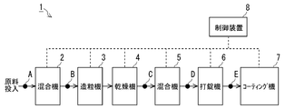
- FIG. 1 is a diagram illustrating a continuous production system according to an embodiment.
- FIG. 2 is a diagram illustrating an example of an inspection and sorting device provided in the continuous production system.
- FIG. 3 is an operation explanatory diagram of the inspection and sorting device.
- FIG. 4 is a flowchart showing the procedure of the production process analysis method according to the present embodiment. It is a graph which shows the principal component score and group for every lot in a 1st process. It is a graph which shows the principal component score and group for every lot in a 2nd process. It is a graph which shows the principal component score and group for every lot in a 3rd process. It is a graph which shows the principal component score and group for every lot in a 4th process.
- FIG. 12 is a diagram illustrating a combination of groups of respective processes corresponding to Cases 4 to 7 in FIG. 11.
- FIG. 13 is a diagram illustrating an example of a process performed by the control device.
- FIG. 14 is a diagram illustrating an example of raw materials classified into a plurality of groups according to characteristics.
- FIG. 15 is a diagram showing an example of a route that appears when the raw material data is taken into the analysis of the production process.
- FIG. 16 is a diagram illustrating a state in which a specific lot follows a scheduled route.
- FIG. 17 is a diagram illustrating a state in which a specific lot deviates from a planned route.
- FIG. 1 is a diagram illustrating a continuous production system 1 according to the embodiment.
- the case where the product is continuously produced from the powder of the raw material will be described as an example. is there.
- a case where a pharmaceutical is manufactured will be described as an example, but the present invention is also applicable to, for example, manufacturing of food and other various products.
- a case where a product is continuously produced from powder will be described as an example.For example, a raw material containing a substance other than powder, or a case where a product is continuously produced from a raw material other than powder, Applicable.
- the continuous production system 1 is a system for producing tablets from a powdery raw material, and as shown in FIG. 1, a mixer 2, a granulator 3, a dryer 4, a mixer 5, a tableting machine 6, a coating machine. 7, a control device 8 for controlling these.
- the mixer 2 has an input port into which the raw material of the powder is input, and mixes various powders and liquids which are the raw materials of the tablet.
- the granulator 3 binds the raw materials mixed by the mixer 2 to a group of small particles to make them into a granular form.
- the dryer 4 adds various additional raw materials to the raw material granulated by the granulator 3 and dries the raw material.
- the mixer 5 mixes the granular raw materials dried by the dryer 4.
- the tableting machine 6 puts the granular raw materials mixed by the mixing machine 5 into a mold and compresses them into tablets.
- the coating machine 7 applies a coating to the tablets solidified by the tableting machine 6.
- a series of equipment from the mixer 2 to the coating machine 7 is connected. Therefore, in the continuous production system 1, various processes performed in a series of facilities from the mixer 2 to the coating machine 7 are continuously performed on the raw material input to the mixer 2.
- FIG. 1 a series of equipment from the mixer 2 to the coating machine 7 is illustrated one by one, but the continuous production system 1 is not limited to such a form.
- one or more mixers 2, granulators 3, and dryers 4 may be prepared, and a plurality of types of raw materials may be mixed by the mixer 5.
- the control device 8 includes a CPU (Central Processing Unit) (an example of a “processing unit”), a memory, and an input / output interface (an example of an “output unit” in the present application) that perform various arithmetic processes.
- the control target value of the machine 7 is determined.
- the measurement values referred to by the control device 8 include, for example, values obtained from each device from the mixer 2 to the coating machine 7 such as a rotation speed of a screw feeder provided in the mixer 2 and a temperature of the dryer 4, and other devices.
- route which connects is included.
- the control device 8 may control the granulator 3 or the granulator 3 according to the properties of the raw material exiting the dryer 4, for example.
- the operation amount of the mixer 5 can be changed.
- control device 8 responds, for example, according to the properties of the raw material leaving the mixer 2.
- the destination of the raw material can be changed to a destination other than the granulator 3.
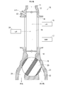
- FIG. 2 is a diagram showing an example of the inspection and sorting device 10 provided in the continuous production system 1.
- the inspection and sorting device 10 can be provided at an appropriate place in the continuous production system 1.
- the inspection and sorting device 10 is provided, for example, in the middle of a path connecting each device from the mixer 2 to the coating machine 7 as shown by reference numerals A to E in FIG.
- the sensors provided in the continuous production system 1 are not limited to those indicated by reference numerals A to E in FIG. 1, but are also provided in each device constituting the continuous production system 1, for example. Then, the control device 8 obtains the temperature, the stirring speed, and various other various measurement values in the device for performing various processes such as the input amount of the raw material, the flow rate, and the heating from the sensors provided at the various places as described above.
- the inspection and sorting apparatus 10 includes an inflow path 11 into which raw materials sent from equipment connected to the upstream side of the inspection and selection apparatus 10 flows, an inlet gate valve 12 installed at a lower end of the inflow path 11, and a lower part of the inlet gate valve 12.
- An inspection chamber 16 formed on the side, an air blowing path 13 provided in the vicinity of the inlet-side gate valve 12, a sight glass 14 which constitutes a wall surface of the inspection room 16 and allows the inside of the inspection room 16 to be seen through from the surroundings,
- An outlet-side gate valve 18 is provided below the glass 14.
- the inspection and sorting device 10 in a state where the inlet-side gate valve 12 is in the open state and the outlet-side gate valve 18 is in the closed state, when raw materials are sent from a device connected to the upstream side of the inspection and sorting device 10, the inspection room 16 is moved to the inspection room 16. Accumulates the raw material. Then, when the laser sensor 15 detects that a predetermined amount of raw material has accumulated in the inspection chamber 16, the inlet-side gate valve 12 is closed, and the raw material is inspected using the spectrometer 17. A flow path switching valve 21 having valve holes 19 and 20 is provided below the outlet-side gate valve 18, and the raw material after the inspection is sent to an outflow path 22 or an outflow path 23 according to the inspection result.
- the presence or absence of the raw material remaining in the inspection room 16 is inspected by the laser sensor 24.
- an example using a near-infrared sensor as an example of the spectrometer 17 will be described.
- the continuous production system disclosed in the present application is not limited to such an embodiment.
- a so-called diverter valve will be described as an example of the flow path switching valve 21.
- the continuous production system disclosed in the present application is not limited to such a form, and the flow of other methods is not limited.
- a device using a road switching mechanism may be used.
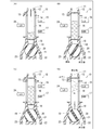
- FIG. 3 is an explanatory diagram of the operation of the inspection and sorting apparatus 10.
- the inspection and sorting device 10 is connected to the control device 8 of the continuous production system 1. Then, the inspection and sorting device 10 operates as follows according to a control signal sent from the control device 8 of the continuous production system 1. That is, in the inspection and sorting device 10, when the raw material is sent from a device connected to the upstream side of the inspection and sorting device 10 in a state where the inlet-side gate valve 12 is in the open state and the outlet-side gate valve 18 is in the closed state, FIG. As shown in (A), raw materials accumulate in the inspection room 16.
- the inlet-side gate valve 12 is closed as shown in FIG.
- the inlet-side gate valve 12 closes, the flow of new raw material from the inflow path 11 to the inspection room 16 stops. While the flow of new raw material from the inflow path 11 to the inspection room 16 is stopped, the bulk density of the raw material in the inspection room 16 is kept constant. Therefore, after the inlet gate valve 12 is closed, the inspection of the raw material in the inspection chamber 16 using the spectrometer 17 is started.
- the switching operation of the flow path switching valve 21 is performed according to the inspection result. For example, when the inspection result of the raw material stored in the inspection room 16 is good, as shown in FIG. 3 (C), the outflow path 22 to which the equipment that performs the next process on the raw material stored in the inspection room 16 is connected. The direction of the flow path switching valve 21 is switched so that is communicated with the valve hole 20. Further, for example, when the inspection result of the raw material accumulated in the inspection room 16 is defective, the direction of the flow path switching valve 21 is set so that the outflow path 23 for discarding the raw material accumulated in the inspection room 16 communicates with the valve hole 19. Switches.
- the inspection chamber is moved from the air blowing path 13 to the inspection room.
- the air blow into the test chamber 16 is started, and the raw material in the test chamber 16 is quickly discharged from the test chamber 16.
- the outlet gate valve 18 is closed, and the optical inspection of the residual raw material is performed using the laser sensor 24.
- the inlet-side gate valve 12 is opened again.
- the inlet-side gate valve 12 When the inlet-side gate valve 12 is opened, the raw material sent from the equipment on the upstream side of the inspection and sorting device 10 and stored above the inlet-side gate valve 12 while the inlet-side gate valve 12 is closed is stored in the inspection chamber 16. Flows into.
- the above-described series of operations described with reference to FIGS. 3A to 3D are repeatedly performed in units of several tens of seconds to several minutes. Therefore, there is almost no possibility that the continuous operation of the devices connected to the upstream and downstream sides of the inspection and sorting apparatus 10 will be substantially hindered.
- Inspection of the raw material using the spectrophotometer 17 is performed with the inlet gate valve 12 closed at a predetermined height detected by the laser sensor 15, so that the bulk density of the raw material is kept constant every time. Will be done. Therefore, there is almost no possibility that the measurement value of the spectrometer 17 fluctuates depending on the bulk density of the powder.
- the inspection selection device 10 even in the continuous production system 1 that continuously produces tablets from a powdery raw material, a measurement value that fluctuates depending on the bulk density of the powder can be obtained with high accuracy. It is possible.
- all of the raw materials that are continuously handled in the continuous production system 1 can be inspected in the inspection room 16 and sorted by the flow path switching valve 21. Even if a defective product is temporarily generated in step 1, it is possible to separate the non-defective product from the non-defective product in the unit of the amount accumulated in the inspection room 16, thereby reducing the amount of discarded raw materials as much as possible. It is possible to do.
- the operation of the continuous production system 1 realized by the control device 8 will be described.
- the following description of the operation content is mainly divided into the content of the preparation stage and the content of the main operation stage.
- the control device 8 determines the control target value of each device based on the information. Information is prepared.
- the control device 8 determines the control target value of each device based on the basic information obtained in the preparation stage.
- the control target value determined by the control device 8 may be automatically set to each device through a control communication path connecting the control device 8 and each device, or may be manually set to each device by an operator. May be set.
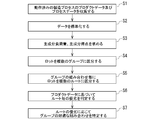
- FIG. 4 is a flowchart showing the procedure of the production process analysis method according to the present embodiment.
- control device 8 collects information on the manufacturing conditions (process data and product data) measured by the sensor (step S1). In this step S1, the process data and product data for each lot are stored in the control device 8.
- step S2 the process data and product data collected in step S1 are standardized and converted into intermediate variables (step S2).
- step S2 The data standardization process performed in step S2 is a known process, and specifically, the control device 8 calculates based on Equation 1.
- step S3 a principal component load and a principal component score are determined based on the intermediate variables determined in step S2 (step S3).
- step 3 first, a correlation coefficient matrix for the intermediate variables is created, and eigenvalues and eigenvectors of the correlation coefficient matrix are derived.
- the first principal component PC1 is expressed as shown in Expression 2.
- the Nth principal component PCn is represented as shown in Expression 3.
- the coefficients a11, a12, a13,... Are used as elements in the first row, and the coefficients an1, an2, an3,.
- the principal component score is obtained from the eigenvector of the correlation coefficient matrix. Further, the contribution rate of each principal component is obtained from the eigenvalue of the correlation coefficient matrix. The contribution ratio of the principal component is obtained by dividing the eigenvalue by the sum of the eigenvalues.
- the first principal component, the second principal component,..., The Nth principal component are determined in descending order of the eigenvalue.
- the control device 8 determines the values of the first principal component PC1, the second principal component PC2,... Based on the intermediate variables x1, x2, x3 of each lot and each coefficient of the correlation coefficient matrix. , Calculate the principal component score.
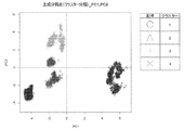
- FIG. 5 is a graph in which the principal component scores are plotted in a coordinate system having the first principal component on the horizontal axis and the second principal component on the vertical axis for the manufacturing conditions in the first step.
- Cluster analysis is a method of classifying analysis target data (clusters) into a plurality of groups by focusing on similarity, and hierarchical clustering, classification optimization clustering, and the like are known.
- the “similarity” of interest in the cluster analysis in the present embodiment refers to the distance between the principal component scores of each lot.
- cohesive hierarchical clustering which is one of hierarchical clustering, is used.
- a Ward method that can stably obtain a solution was used as a method for calculating the distance between clusters.
- the “Ward method” is to select a cluster that minimizes the increase in the sum of squares of deviation when two clusters are merged. For example, when the clusters C are generated by merging the clusters A and B, the sums of squares of deviations Sa, Sb, and Sc in the clusters A, B, and C are represented by Equations 4 to 6, respectively.
- ⁇ ⁇ Sab in equation 7 means the increment of the sum of squared deviations when clusters A and B are merged to generate cluster C. Therefore, clustering is advanced by selecting and merging clusters such that ⁇ Sab is minimized at each merging stage.
- the data is divided into six groups 1 to 6 in a five-dimensional space including first to fifth eigenvectors.
- groups 1 to 6 correspond to clusters 1 to 6 in FIG. 5, respectively.
- the number of groups is not limited to six, and may be five or less or seven or more as long as the number is easy to handle.
- the principal component scores are plotted on a graph and divided into a plurality of groups.
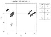
- 6 to 10 are graphs showing principal component scores and groups (clusters) for the manufacturing conditions in the second to sixth steps.
- the lot generation process is divided into a plurality of routes for each combination of the groups in the first to sixth steps (step S5).
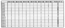
- the routes are classified into 16 routes.
- FIG. 11 shows a breakdown of all routes. Note that “Case” in FIG. 11 corresponds to the above-described route, and the numbers in FIG. 11 correspond to the numbers of the groups in the first to sixth steps.
- FIG. 12 shows routes corresponding to Cases 4 to 7 as an example of combinations of groups constituting the routes.
- step S6 the control device 8 calls an intermediate variable obtained from the product data (such as the appearance inspection failure rate) for each lot belonging to Cases 1 to 16 in FIG. 11 and determines the superiority or inferiority of these product data.
- the control device 8 calls an intermediate variable obtained from the product data (such as the appearance inspection failure rate) for each lot belonging to Cases 1 to 16 in FIG. 11 and determines the superiority or inferiority of these product data.
- the superiority or inferiority of the product data is determined based on an average value in a plurality of lots (lot groups) divided for each route. As a result, the variation of the product data of the lot group in the route is leveled, and the tendency of the quality of the product data between the routes can be grasped globally.
- the superiority of the product data may be determined based on the magnitude of the deviation of the product data in the route or the magnitude of the difference (range) between the maximum value and the minimum value, or two values such as an average value, a deviation, or an R value. The determination may be made in combination of the above. As an example of judging the superiority of the product data by combining the average value and the deviation, for example, when the average value in the route is the same, it is conceivable to determine the one with the smaller deviation in the route as superior. This makes it possible to globally grasp the tendency of the product data between routes taking into account the variation of the product data within the route.
- control device 8 compares the product data for each route and determines the superiority or inferiority.
- the failure rate of appearance inspection as product data in each route is evaluated in three levels of excellent, good, and acceptable according to their superiority.
- a suitable combination of the groups of the first to sixth steps is specified according to the superiority of the product data for each route (step S7). For example, comparing Cases 4 and 5 determined to be excellent with Cases 6 and 7 determined to be good, these are the same group in the first, second, fourth, and sixth steps, The third step is a different group. Further, it is assumed that the fifth step does not significantly affect the product data in any of groups 1 and 2. In other words, it can be seen that it is preferable to combine the third step group 1 with the route that has passed through the first step group 2 and the second step group 2.
- Case 14 determined to be excellent indicates that although the first to fourth and sixth steps belong to the same group, they differ in the fifth step. It is. That is, group 5 of the first step, group 3 of the second step, group 4 of the third step, group 2 of the fourth step, group 1 of the fifth step, and group 1 of the sixth step It turns out that a combination is preferable.
- the “suitable combination” in the present embodiment means a combination that contributes to the improvement of the product data, and does not intend only the combination having the best product data.
- the average value of the process data of each group is set to the initial value of the manufacturing conditions, and the quality of the product data at this time is checked. It is preferable to finely adjust the manufacturing conditions while doing so.
- the average value of the process data is set to the initial value, a preferable combination of the first to sixth process groups can be reproduced without departing from the past state, that is, without imposing an excessive load on the manufacturing equipment. can do.
- the continuous production system In the continuous production system 1, when a powdery raw material is put into the mixer 2, mixing of powder and liquid of the raw material is performed in the mixer 2, and the raw material mixed by the mixer 2 is bound to a small particle group.
- the granulating process is performed in the granulator 3, the raw material granulated by the granulator 3 is dried in the dryer 4, and the raw material dried in the dryer 4 is mixed in the mixer 5.
- the process of compressing the raw materials mixed by the mixer 5 into tablets is performed in the tableting machine 6, and the process of coating the tablets is performed in the coating machine 7.
- the control device 8 executes a process of changing the control target value of each device and a process of switching a valve provided in the middle of the path so that a series of devices from the mixer 2 to the coating machine 7 operate properly. At that time, the control device 8 executes a process of changing the control target value of each device and a process of switching a valve provided in the middle of the path based on the basic information obtained in the above-described preparation
- FIG. 13 is a diagram illustrating an example of a process performed by the control device 8.
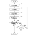
- the control device 8 executes the processing flow shown in FIG. That is, when each facility of the continuous production system 1 operates, the control device 8 acquires information on current manufacturing conditions of each process (S11). Then, the control device 8 selects any one of the plurality of routes created in the preparation stage (S12). The selection of the route is performed based on the acquired information on the current manufacturing conditions.
- the first step in the processes realized in the continuous production system 1 is performed by the mixer 2. Therefore, the control device 8 transmits the information on the current manufacturing conditions acquired from the mixer 2. Make a route selection based on that.
- the control device 8 From among the two routes (Cases 14 to 15) that can be taken by the group 5, the route of Case 14 in which the quality of the final product is relatively good is selected.
- the control device 8 sets the control target value of each device of the continuous production system 1 so that the manufacturing conditions are along the selected route (S13).
- the control device 8 setting the control target value of each device, each device of the continuous production system 1 performs an operation according to the control target value set by the control device 8.
- the control device 8 sets the control target value of each device of the continuous production system 1 that performs each process to the default value of each process in the case of Case 14 illustrated in FIG.
- a control target value for each device is set so that the manufacturing conditions are satisfied. Thereby, each device of the continuous production system 1 performs an operation according to the control target value set by the control device 8. If there is no particular abnormality, each lot follows predetermined manufacturing conditions as indicated by a specific route in FIG.
- the controller 8 acquires the current manufacturing conditions in each process (S14), and acquires the current manufacturing conditions in each process. (S15) to determine whether or not the manufacturing conditions specified by the route selected in step S12 are being met. Then, when a negative determination is made in step S15, the control device 8 executes a process (S16) of determining whether to change the route selected in step S12.
- step S15 the difference between the allowable manufacturing conditions is set for each of the manufacturing conditions specified for each route in FIG. 12, and the current manufacturing condition acquired in step S14 is set to the difference. May be performed depending on whether or not it is within the range, or the manufacturing conditions defined for each route in FIG. 12 may define an upper limit value and a lower limit value in advance. The process may be performed depending on whether or not the current manufacturing condition acquired in S14 is between the upper limit value and the lower limit value.
- step S16 may be, for example, a process in which an operator is notified that the current manufacturing conditions deviate from the route, and the operator is required to determine whether or not the route can be changed.
- the control device 8 refers to information on a plurality of routes as shown in FIG. 12 and determines whether there is another alternative route different from the route selected in step S12. Good.
- the above-described series of processing is executed by the control device 8, and the production conditions of some routes that have already been confirmed to be able to maintain quality by past production results Is performed for each lot so as to meet the requirements. That is, in the continuous production system 1, by executing the above-described processing by the control device 8, the optimal control target value based on the past production results is set according to the current production state. The quality of the product can be further stabilized as compared with a case where a fixed control target value is uniformly set for each device regardless of the manufacturing state as conventionally performed.
- the continuous production system 1 is a system for continuously producing tablets, which are pharmaceuticals, from powdery raw materials, if a positive determination is made in step S15, the corresponding lot flows to the next process. Preventive processing may be performed.
- the process of preventing a specific lot from flowing to the next process can be realized, for example, by using the inspection and sorting device 10 arranged at an appropriate place in the continuous production system 1 as follows.
- an example of an entire control flow that can be realized by the continuous production system 1 when the inspection and sorting device 10 is installed at reference numeral C in FIG. 1 will be described.
- the dryer 4 of the continuous production system 1 shown in FIG. 1 various additional raw materials are added to the raw material granulated by the granulator 3 and drying is performed.
- the dryer 4 is provided with one or more heaters for performing heating and drying, and the control device 8 adjusts the amount of current supplied to the heaters so as to obtain an appropriate drying temperature.
- the dryer 4 is provided with a variable speed blower, and the rotation speed of the blower is controlled by the controller 8 so that the raw material granulated by the granulator 3 passes through the dryer 4 at an appropriate wind speed. It is adjusted by.
- the above-described inspection and sorting device 10 is installed in the middle of the path connecting the dryer 4 and the mixer 5, that is, at the site indicated by the symbol C in FIG. In the case of deviation, it is possible to prevent the raw material to be continuously processed from flowing to the mixer 5 which is responsible for the next step. Therefore, it is possible to transfer the raw material to equipment other than the mixer 5 to perform appropriate processing, or to discharge the raw material to the outside of the continuous production system 1.
- the control device 8 collects information on the manufacturing conditions (process data and product data) for the operated production process (step S1). At this time, in the above embodiment, the information on the manufacturing conditions measured by the sensor is collected. However, in this modification, in addition to the process data measured by the sensor, the raw material data (physical properties, composition, and the like of the raw material) are also obtained. Collected.
- the raw material data is provided from, for example, a raw material maker.
- step S2 a process of standardizing data (step S2) and a process of calculating a principal component load and a principal component score based on intermediate variables (step S3)
- step S4 Processing for dividing a lot into a plurality of groups (step S4), processing for dividing a lot generation process into a plurality of routes for each combination of groups (step S5), and processing for judging the superiority of product data for each route (step S5) S6), a process of specifying a suitable combination of groups (step S7) is performed.
- step S2 data standardization processing based on the above-described formula 1 is performed. Further, in step S3, after the creation of the correlation coefficient matrix for the intermediate variables and the derivation of the eigenvalues and eigenvectors of the correlation coefficient matrix, a principal component score is obtained from the eigenvectors of the correlation coefficient matrix. The contribution ratio of each principal component is obtained from the eigenvalues of the numerical matrix. In step S4, a process of applying a cluster analysis to the principal component scores to divide each lot into a plurality of groups is performed.
- step S6 after the processing in step S5, the intermediate variables obtained from the product data (such as the appearance inspection failure rate) are called for each lot, and the superiority or inferiority of these product data is determined, so that each route is determined. Of product data is judged. Further, in step S7, by comparing the superiority and the inferiority of the product data for each route, the combination of the groups of the respective processes whose quality is relatively good is specified.
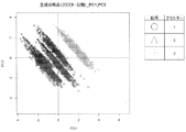
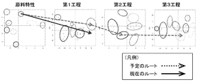
- FIG. 14 is a diagram showing an example of raw materials classified into a plurality of groups according to characteristics.
- various raw materials such as powders have some variation in characteristics depending on lots, even for the same product purchased from a specific manufacturer. Therefore, in this modification, such information on the characteristics of the raw material is incorporated into the analysis of the production process as raw material data. Therefore, when a production process is analyzed based on past production results, there may be cases where there are some routes according to the raw material characteristics, in which the quality of the final product is relatively good.
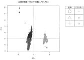
- FIG. 15 is a diagram showing an example of a route that appears when the raw material data is taken into the analysis of the production process. Since the characteristics of various raw materials such as powders vary slightly depending on the lot, the raw material data is standardized and converted into intermediate variables, and the principal component score is obtained. As shown in the “Characteristics” graph, variations in the raw material characteristics appear on the graph. In the present modification, a process is performed in which each raw material is divided into a plurality of groups by applying cluster analysis to the principal component scores indicating variations in raw material characteristics.
- the superiority of the product data is determined for each route, As shown in FIG. 15, several routes starting from the raw material characteristics are extracted.
- control device 8 of this modification when each facility of the continuous production system 1 operates, a processing flow equivalent to that shown in FIG. 13 is executed. That is, when each facility of the continuous production system 1 operates, the control device 8 acquires the manufacturing conditions (S11). At this time, the control device 8 acquires raw material data as manufacturing conditions. The raw material data is input, for example, by an operation of an operator. Then, the control device 8 selects any one of the plurality of routes created in the preparation stage (S12). The route is selected based on the acquired raw material data. Then, after selecting the route, the control device 8 sets the control target value of each device of the continuous production system 1 so that the manufacturing conditions are along the selected route (S13).
- each device of the continuous production system 1 the operation according to the control target value set by the control device 8 is performed, and if there is no special abnormality, as shown in FIG. Will be traced by the current lot.
- the process of acquiring the information on the current manufacturing conditions in each process (S14) and the obtained current manufacturing conditions are selected in step S12.
- the process (S15) of determining whether or not the manufacturing condition is set according to the route is determined.
- step S15 when the current lot deviates from the selected scheduled route, a negative determination is made in step S15. Then, a process (S16) of determining whether to change the route selected in step S12 is executed.
- the above-described series of processing is executed by the control device 8 of the present modified example.
- Each lot is processed so as to meet the manufacturing conditions of some routes for which it has been confirmed that the quality can be maintained by the production results. Therefore, for example, the quality of the product can be further stabilized as compared with a case where a fixed control target value is uniformly set for each device regardless of the characteristics of the raw materials and the manufacturing state.
Abstract
The present invention addresses the problem of stabilizing the qualities of products which are manufactured by a plurality of steps. The present invention is a production system for producing products from raw materials by a production process including a plurality of steps, and is provided with: a plurality of production facilities that perform the steps; and a control device that determines control target values which are respectively set for the plurality of production facilities. When information about the properties of a raw material which is charged in the production process is acquired, the control device determines a control target value to be set for at least any one of the plurality of production facilities, by referring to information about group combinations specified in accordance with the relative merits of the manufacturing condition routes followed by respective lots during the production process, the routes being respectively set for a plurality of groups which are classified on the basis of raw material properties each formed of a combination of a plurality of property items of one or more types of raw materials, the relative merits of the routes being determined on the basis of quality items of the lots, classified for each of inter-step combinations of a plurality of groups which are classified on the basis of manufacturing conditions at the steps.
Description
本発明は、生産システム、生産方法、制御装置、及び生産プロセスの解析方法に関する。
The present invention relates to a production system, a production method, a control device, and a production process analysis method.
医薬品や食品の製造においては、製品の品質を維持するために各種工程の制御目標値や上限値、下限値が決定されている。例えば、医薬品の錠剤の製造においては、最終製品となる錠剤が所定の溶質性となるように、粉粒体に各種処理を施す造粒機や乾燥機の制御目標値が決定される。生産プロセスにおけるこのような制御目標値は、様々な方法で決定される(例えば、特許文献1-2を参照)。
In the production of pharmaceuticals and foods, control target values, upper limit values, and lower limit values for various processes are determined in order to maintain product quality. For example, in the manufacture of pharmaceutical tablets, control target values of a granulator or a dryer that performs various treatments on a granular material are determined so that a tablet as a final product has a predetermined solute. Such a control target value in the production process is determined by various methods (for example, see Patent Documents 1-2).
例えば、粉体の原料を取り扱う製造現場では、混合や造粒、乾燥といった各工程を担う装置がそれぞれ用意され、各工程間における原料(以下、「中間製品」も含む)の移動が配管を用いて連続的に行われたり、或いは、容器を用いて間欠的に行われたりする。よって、各工程に流入する原料の状態は、上位工程で行われた処理の内容や、原料メーカーから出荷された際の原料の特性といった各種の影響を不可避的に受けることとなる。したがって、各工程を担う装置の制御目標値は、一意的に定まるものでなく、経験や推測に基づいて動的に調整される場合がある。
For example, at a manufacturing site that handles powdered raw materials, devices that perform various processes such as mixing, granulation, and drying are prepared, and the movement of raw materials (hereinafter, also referred to as “intermediate products”) between the processes is performed using piping. Performed continuously or intermittently using a container. Therefore, the state of the raw material flowing into each process is inevitably affected by various effects such as the content of the processing performed in the upper-level process and the characteristics of the raw material when shipped from the raw material maker. Therefore, the control target value of the device that performs each process is not uniquely determined, and may be dynamically adjusted based on experience or estimation.
しかしながら、様々な工程を有する生産システムの場合、最終製品の状態は、様々な工程で行われた多数の処理内容が相互に影響し合った結果であるため、例えば、特定の工程で用いられている制御目標値の変更を試みながらプロセス全体を改善することは容易でない。
However, in the case of a production system having various processes, the state of the final product is a result of a number of processes performed in various processes interacting with each other. It is not easy to improve the overall process while trying to change certain control target values.
そこで、本発明は、複数の工程を経て製造される製品の品質を安定化させることを解決課題とする。
Therefore, an object of the present invention is to stabilize the quality of a product manufactured through a plurality of steps.
上記課題を解決するため、本発明では、過去に各ロットが生産プロセスを経る際に辿った製造条件のルートの優劣に応じて特定されたグループの組み合わせの情報を基に、生産設備の制御目標値を決定することにした。
In order to solve the above-mentioned problems, the present invention provides a method for controlling production equipment based on information on a combination of groups specified according to the superiority of the route of the manufacturing conditions traced when each lot goes through a production process in the past. I decided to determine the value.
また、本発明は、複数の工程を有する生産プロセスによって、原料から製品を生産する生産システムであって、工程を担う複数の生産設備と、複数の生産設備に各々設定される制御目標値を決定する制御装置と、を備え、制御装置は、生産プロセスに投入される原料の特性の情報を取得すると、一種以上の原料における複数項目の特性の組み合わせからなる原料特性毎に区分された複数のグループに各々設定されるルートであり、各工程において製造条件毎に区分された複数のグループの工程間における組み合わせ毎に区分された各ロットの品質項目に基づいて優劣が判定された、各ロットが生産プロセスを経る際に辿った製造条件のルートの優劣に応じて特定されたグループの組み合わせの情報を参照し、複数の生産設備のうち少なくとも何れかに設定される制御目標値を決定する、生産システムである。
Further, the present invention is a production system for producing a product from a raw material by a production process having a plurality of steps, and determines a plurality of production facilities that carry out the steps and a control target value set for each of the plurality of production facilities. And a control device that, when acquiring the information on the characteristics of the raw materials supplied to the production process, controls the plurality of groups classified for each raw material characteristic including a combination of characteristics of a plurality of items in one or more raw materials. Are determined based on the quality item of each lot classified for each combination between the processes of a plurality of groups classified for each manufacturing condition in each process. Refer to the information of the combination of groups specified according to the superiority of the route of the manufacturing conditions followed during the process, and at least Determining a control target value that is set to any a production system.
ここで、製造条件とは、生産プロセスにおける各種の計測値、制御量、その他の情報を含む概念であり、例えば、上限値や下限値といった閾値に限定されるものではない。また、情報を取得するとは、制御装置が情報を能動的に取得する態様に限定されるものでなく、例えば、オペレータが手動で情報を入力する場合のように、制御装置が情報を受動的に取得する態様も含まれる概念である。
Here, the manufacturing condition is a concept including various measured values, control amounts, and other information in the production process, and is not limited to a threshold such as an upper limit or a lower limit. Further, acquiring information is not limited to a mode in which the control device actively acquires information. For example, the control device passively acquires information, such as when an operator manually inputs information. This is a concept that includes a mode of acquiring.
上記の生産システムであれば、生産プロセスに投入される原料の特性の情報を基に、過去の生産実績に基づいた制御目標値の決定が行われる。よって、製造状態に関わり無く一律に固定の制御目標値を各機器に設定する場合に比べると、製品の品質をより安定化させることができる。
で あ れ ば In the above-described production system, the control target value is determined based on past production results based on information on the characteristics of the raw materials supplied to the production process. Therefore, the quality of the product can be further stabilized as compared with a case where a fixed control target value is uniformly set for each device regardless of the manufacturing state.
なお、制御装置は、グループの組み合わせのうち少なくとも製品の品質の条件が満たされる何れかの組み合わせの情報を参照し、複数の生産設備のうち少なくとも何れかに設定される制御目標値を決定してもよい。制御目標値がこのようにして決定されれば、品質の条件を満たす製品の生産が可能となる。
In addition, the control device refers to information of any combination that satisfies at least the condition of the quality of the product among the combinations of the groups, determines the control target value set in at least one of the plurality of production facilities, Is also good. If the control target value is determined in this way, it is possible to produce a product that satisfies the quality condition.
また、制御装置は、決定した制御目標値を複数の生産設備のうち少なくとも何れかに設定してもよい。制御目標値の設定がこのように行われれば、例えば、制御目標値を製造状態の変化に応じて自律的に変更させることが可能となる。
The control device may set the determined control target value in at least one of the plurality of production facilities. If the control target value is set in this manner, for example, the control target value can be autonomously changed according to a change in the manufacturing state.
また、制御装置は、生産プロセスで製品が生産されている状態において、複数の工程のうち少なくとも何れかの工程の状態を示す製造条件の情報を取得すると、取得した情報を基に、製品のロットがルートの製造条件に沿っているか否かの判定を行ってもよい。このような判定が行われれば、製造条件に沿っていないロットの発生を検知することが可能となる。
Further, in a state where the product is being produced in the production process, the control device acquires the information of the manufacturing condition indicating the state of at least one of the plurality of processes, and based on the acquired information, the lot number of the product. It may be determined whether or not is in line with the manufacturing conditions of the route. If such a determination is made, it is possible to detect the occurrence of a lot that does not meet the manufacturing conditions.
また、組み合わせの情報は、工程毎の状態を示す製造条件及び製品の品質を示す品質項目を含むデータを生産プロセスのロット毎に収集し、工程の製造条件に応じて各工程を複数のグループに区分し、グループの組み合わせ毎にロットを複数のルートに区分し、ルートの品質項目に応じてルートの優劣を判定し、ルートの優劣に応じて特定されたグループの好適な組み合わせの情報であってもよい。このようにして作成された組み合わせの情報であれば、過去の生産実績により製品の品質の優劣が把握されたルートで制御目標値の決定が可能となる。
In addition, as for the information of the combination, data including manufacturing conditions indicating the state of each process and quality items indicating the quality of the product are collected for each lot of the production process, and each process is divided into a plurality of groups according to the manufacturing conditions of the process. Sorting, dividing the lot into a plurality of routes for each combination of groups, judging the superiority of the route according to the quality item of the route, and information on a suitable combination of the group specified according to the superiority of the route. Is also good. With the information of the combination created in this way, it is possible to determine the control target value on a route in which the quality of the product is determined based on past production results.
また、生産プロセスは、原料の粉体から製品を連続生産する連続生産プロセスであり、複数の生産設備は、原料の粉体に第1の処理を行う第1処理装置と、第1処理装置が第1の処理を行った粉体へ第2の処理を行う第2処理装置と、第1処理装置から送られた粉体が流入する検査室を有する検査選別装置と、を有し、検査選別装置は、検査室に所定量の粉体が溜まると、第1処理装置から検査室へ繋がる経路を閉鎖した後に検査室内の粉体の検査を実行し、検査を終えると、検査室内から粉体を排出した後に閉鎖を解除する装置であり、制御装置は、検査選別装置で検査室内の粉体の特性の情報を取得すると、組み合わせの情報を参照し、第2処理装置に設定される制御目標値を決定するものであってもよい。このような生産システムであれば、例えば、粉状の原料から製品を連続的に生産する場合においても粉体の特性の情報が精度良く得られるため、過去の生産実績に基づいた制御目標値の決定を適切に行うことができる。
Further, the production process is a continuous production process for continuously producing a product from raw material powder, and the plurality of production facilities include a first processing device that performs first processing on the raw material powder and a first processing device. A second processing apparatus for performing the second processing on the powder that has been subjected to the first processing, and an inspection and sorting apparatus having an inspection chamber into which the powder sent from the first processing apparatus flows, and the inspection and sorting are performed. When a predetermined amount of powder accumulates in the inspection room, the device performs inspection of the powder in the inspection room after closing the path leading from the first processing device to the inspection room, and when the inspection is completed, the powder is removed from the inspection room. The control device refers to the combination information when the information of the characteristics of the powder in the inspection room is acquired by the inspection selection device, and the control target set in the second processing device. The value may be determined. With such a production system, for example, even in the case of continuously producing a product from a powdery raw material, information on the characteristics of the powder can be obtained with high accuracy, so that a control target value based on past production results can be obtained. The decision can be made appropriately.
また、制御装置は、組み合わせの情報を参照した結果、検査室内の粉体が何れのグループにも区分されない場合、検査選別装置に検査室内の粉体を第2処理装置へ排出させないものであってもよい。このような生産システムであれば、ルートから逸脱したロットが第2処理装置へ送られるのを防ぐことが可能となる。
Further, as a result of referring to the information on the combination, if the powder in the inspection room is not classified into any group, the control device does not cause the inspection selection device to discharge the powder in the inspection room to the second processing device. Is also good. With such a production system, it is possible to prevent a lot deviating from the route from being sent to the second processing apparatus.
また、本発明は、方法の側面から捉えることもできる。例えば、本発明は、複数の工程を有する生産プロセスによって、原料から製品を生産する生産方法であって、工程を担う複数の生産設備を作動させる工程と、複数の生産設備に各々設定される制御目標値を制御装置に決定させる工程と、を有し、制御装置に決定させる工程では、前記生産プロセスに投入される原料の特性の情報を取得すると、一種以上の原料における複数項目の特性の組み合わせからなる原料特性毎に区分された複数のグループに各々設定されるルートであり、各工程において製造条件毎に区分された複数のグループの工程間における組み合わせ毎に区分された各ロットの品質項目に基づいて優劣が判定された、前記各ロットが前記生産プロセスを経る際に辿った製造条件のルートの優劣に応じて特定された前記グループの組み合わせの情報を参照し、前記複数の生産設備のうち少なくとも何れかに設定される制御目標値を決定するものであってもよい。
本 The present invention can also be grasped from the aspect of a method. For example, the present invention is a production method for producing a product from a raw material by a production process having a plurality of steps, wherein a step of operating a plurality of production facilities for performing the steps and a control set for each of the plurality of production facilities are provided. A step of causing the control device to determine the target value, and in the step of causing the control device to determine, when acquiring information on the characteristics of the raw materials supplied to the production process, a combination of characteristics of a plurality of items in one or more raw materials These are routes that are set for each of a plurality of groups that are classified according to the raw material characteristics, and that include the quality items of each lot classified for each combination between the processes of the plurality of groups that are classified for each manufacturing condition in each process. The priority of the group is determined based on the superiority of the route of the manufacturing conditions followed when each lot goes through the production process. The information in the combined look, may be configured to determine the control target value set to at least one of said plurality of production facilities.
また、本発明は、制御装置の側面から捉えることもできる。例えば、本発明は、複数の工程を有する生産プロセスによって、原料から製品を生産する生産システムの制御装置であって、工程を担う複数の生産設備に各々設定される制御目標値を決定する処理を実行する処理部と、処理部が決定した制御目標値を出力する出力部と、を備え、処理部は、生産プロセスに投入される原料の特性の情報を取得すると、一種以上の原料における複数項目の特性の組み合わせからなる原料特性毎に区分された複数のグループに各々設定されるルートであり、各工程において製造条件毎に区分された複数のグループの工程間における組み合わせ毎に区分された各ロットの品質項目に基づいて優劣が判定された、各ロットが生産プロセスを経る際に辿った製造条件のルートの優劣に応じて特定されたグループの組み合わせの情報を参照し、複数の生産設備のうち少なくとも何れかに設定される制御目標値を決定するものであってもよい。
The present invention can also be grasped from the aspect of the control device. For example, the present invention is a control device of a production system that produces a product from raw materials by a production process having a plurality of processes, and performs a process of determining a control target value that is set for each of a plurality of production facilities that perform the process. A processing unit to be executed, and an output unit that outputs a control target value determined by the processing unit, and the processing unit obtains information on characteristics of the raw material to be input to the production process. Routes set for each of a plurality of groups classified for each raw material characteristic composed of a combination of characteristics, and each lot classified for each combination between a plurality of groups of processes classified for each manufacturing condition in each process. Combination of groups specified according to the superiority of the route of the manufacturing conditions followed when each lot goes through the production process, with superiority judged based on the quality item of The information in the allowed, may be configured to determine the control target value set to at least one of the plurality of production facilities.
また、本発明は、解析方法の側面から捉えることもできる。例えば、本発明は、複数の工程で構成され、原料から製品を生産する生産プロセスの解析方法であって、生産プロセスに投入される原料の特性の情報と、複数の工程のうち少なくとも何れかの工程の状態を示す製造条件の情報とを、生産プロセスのロット毎に取得するステップと、原料の特性及び工程の製造条件に応じて、前記原料を一種以上の原料における複数項目の特性の組み合わせからなる原料特性毎のグループ、及び、各工程を複数のグループに区分するステップと、グループの組み合わせ毎にロットを複数のルートに区分するステップと、ルートの品質項目に応じてルートの優劣を判定するステップと、ルートの優劣に応じて、グループの好適な組み合わせを特定するステップと、を有する、生産プロセスの解析方法であってもよい。
本 The present invention can also be grasped from the aspect of the analysis method. For example, the present invention is a method of analyzing a production process that includes a plurality of steps and produces a product from a raw material, and includes information on characteristics of a raw material input to the production process and at least one of the plurality of steps. Information on the manufacturing conditions indicating the state of the process, the step of obtaining for each lot of the production process, and according to the characteristics of the raw materials and the manufacturing conditions of the process, the raw materials are obtained from a combination of the characteristics of a plurality of items in one or more raw materials. Grouping each raw material characteristic and each process into a plurality of groups; dividing each lot into a plurality of routes for each combination of groups; and judging the superiority of the routes according to the quality items of the routes. The method for analyzing a production process may include a step and a step of specifying a suitable combination of groups according to the priority of the route. .
上記の生産システム、生産方法、制御装置、及び生産プロセスの解析方法であれば、複数の工程を経て製造される製品の品質を安定化させることが可能である。
With the above-described production system, production method, control device, and production process analysis method, it is possible to stabilize the quality of products manufactured through a plurality of steps.
以下、実施形態について説明する。以下に示す実施形態は、単なる例示であり、本開示の技術的範囲を以下の態様に限定するものではない。
Hereinafter, embodiments will be described. The embodiments described below are merely examples, and do not limit the technical scope of the present disclosure to the following aspects.
<ハードウェア構成>
図1は、実施形態に係る連続生産システム1を示した図である。本実施形態では、原料の粉体から製品を連続生産する場合を例に説明するが、例えば、各工程を担う装置間で原料が容器等により間欠的に移動されるバッチ式にも適用可能である。また、本実施形態では、医薬品を製造する場合を例に説明するが、例えば、食品やその他各種製品の製造にも適用可能である。また、本実施形態では、粉体から製品を連続生産する場合を例に説明するが、例えば、粉体以外の物質を含む原料、或いは、粉体以外の原料から製品を連続生産する場合にも適用可能である。 <Hardware configuration>
FIG. 1 is a diagram illustrating acontinuous production system 1 according to the embodiment. In the present embodiment, the case where the product is continuously produced from the powder of the raw material will be described as an example. is there. Further, in the present embodiment, a case where a pharmaceutical is manufactured will be described as an example, but the present invention is also applicable to, for example, manufacturing of food and other various products. Further, in the present embodiment, a case where a product is continuously produced from powder will be described as an example.For example, a raw material containing a substance other than powder, or a case where a product is continuously produced from a raw material other than powder, Applicable.
図1は、実施形態に係る連続生産システム1を示した図である。本実施形態では、原料の粉体から製品を連続生産する場合を例に説明するが、例えば、各工程を担う装置間で原料が容器等により間欠的に移動されるバッチ式にも適用可能である。また、本実施形態では、医薬品を製造する場合を例に説明するが、例えば、食品やその他各種製品の製造にも適用可能である。また、本実施形態では、粉体から製品を連続生産する場合を例に説明するが、例えば、粉体以外の物質を含む原料、或いは、粉体以外の原料から製品を連続生産する場合にも適用可能である。 <Hardware configuration>
FIG. 1 is a diagram illustrating a
連続生産システム1は、粉状の原料から錠剤を生産するシステムであり、図1に示すように、混合機2、造粒機3、乾燥機4、混合機5、打錠機6、コーティング機7、これらを制御する制御装置8を備える。混合機2は、粉体の原料が投入される投入口を有し、錠剤の原料である各種の粉や液体を混合する。造粒機3は、混合機2で混合された原料を小粒子群に結着させて粒状にする。乾燥機4は、造粒機3で造粒された原料に各種の追加原料を加えて乾燥させる。混合機5は、乾燥機4で乾燥された粒状の原料を混合する。打錠機6は、混合機5で混合された粒状の原料を型枠に入れて圧縮し、錠剤にする。コーティング機7は、打錠機6で固化された錠剤にコーティングを施す。連続生産システム1では、混合機2からコーティング機7へ至る一連の設備が繋がっている。よって、連続生産システム1では、混合機2に投入された原料に対し、混合機2からコーティング機7へ至る一連の設備でそれぞれ行われる様々な処理が連続的に行われる。
The continuous production system 1 is a system for producing tablets from a powdery raw material, and as shown in FIG. 1, a mixer 2, a granulator 3, a dryer 4, a mixer 5, a tableting machine 6, a coating machine. 7, a control device 8 for controlling these. The mixer 2 has an input port into which the raw material of the powder is input, and mixes various powders and liquids which are the raw materials of the tablet. The granulator 3 binds the raw materials mixed by the mixer 2 to a group of small particles to make them into a granular form. The dryer 4 adds various additional raw materials to the raw material granulated by the granulator 3 and dries the raw material. The mixer 5 mixes the granular raw materials dried by the dryer 4. The tableting machine 6 puts the granular raw materials mixed by the mixing machine 5 into a mold and compresses them into tablets. The coating machine 7 applies a coating to the tablets solidified by the tableting machine 6. In the continuous production system 1, a series of equipment from the mixer 2 to the coating machine 7 is connected. Therefore, in the continuous production system 1, various processes performed in a series of facilities from the mixer 2 to the coating machine 7 are continuously performed on the raw material input to the mixer 2.
なお、図1では、混合機2からコーティング機7へ至る一連の機器が1つずつ図示されているが、連続生産システム1はこのような形態に限定されるものではない。例えば、混合機2や造粒機3、乾燥機4が1乃至複数用意されており、複数種の原料が混合機5で混合されるようにしてもよい。
In FIG. 1, a series of equipment from the mixer 2 to the coating machine 7 is illustrated one by one, but the continuous production system 1 is not limited to such a form. For example, one or more mixers 2, granulators 3, and dryers 4 may be prepared, and a plurality of types of raw materials may be mixed by the mixer 5.
混合機2からコーティング機7へ至る一連の設備は、制御装置8によって制御される。制御装置8は、各種の演算処理を担うCPU(Central Processing Unit)(本願でいう「処理部」の一例である)やメモリ、入出力インターフェース(本願でいう「出力部」の一例である)を有しており、連続生産システム1において実現される生産プロセスの各工程における製造条件の情報を基に、混合機2や造粒機3、乾燥機4、混合機5、打錠機6、コーティング機7の制御目標値を決定する。制御装置8が参照する計測値としては、例えば、混合機2に備わるスクリューフィーダーの回転速度や乾燥機4の温度といった混合機2からコーティング機7までの各機器から得られる値の他、各機器を繋ぐ経路の途中に設けられたセンサから得られる値が含まれる。各機器を繋ぐ経路の途中に設けられるセンサの位置としては、例えば、図1において符号A~Eで示されるような位置が挙げられる。乾燥機4と混合機5とを繋ぐ経路の途中にある符号Cにセンサが設置されていれば、制御装置8は、例えば、乾燥機4を出た原料の性状に応じて造粒機3や混合機5の操作量を変更することができる。また、例えば、混合機2と造粒機3とを繋ぐ経路の途中にある符号Bにセンサが設置されていれば、制御装置8は、例えば、混合機2を出た原料の性状に応じて当該原料の行先を造粒機3以外へ変更することが可能となる。
一連 A series of equipment from the mixer 2 to the coating machine 7 is controlled by the controller 8. The control device 8 includes a CPU (Central Processing Unit) (an example of a “processing unit”), a memory, and an input / output interface (an example of an “output unit” in the present application) that perform various arithmetic processes. The mixer 2, the granulator 3, the dryer 4, the mixer 5, the tableting machine 6, the coating machine, etc., based on the information on the manufacturing conditions in each step of the production process realized in the continuous production system 1. The control target value of the machine 7 is determined. The measurement values referred to by the control device 8 include, for example, values obtained from each device from the mixer 2 to the coating machine 7 such as a rotation speed of a screw feeder provided in the mixer 2 and a temperature of the dryer 4, and other devices. The value obtained from the sensor provided in the middle of the path | route which connects is included. As the position of the sensor provided in the middle of the path connecting the devices, for example, the positions indicated by reference numerals A to E in FIG. If a sensor is installed at the symbol C in the middle of the path connecting the dryer 4 and the mixer 5, the control device 8 may control the granulator 3 or the granulator 3 according to the properties of the raw material exiting the dryer 4, for example. The operation amount of the mixer 5 can be changed. Further, for example, if a sensor is installed at the symbol B in the middle of the path connecting the mixer 2 and the granulator 3, the control device 8 responds, for example, according to the properties of the raw material leaving the mixer 2. The destination of the raw material can be changed to a destination other than the granulator 3.
図2は、連続生産システム1に備わる検査選別装置10の一例を示した図である。検査選別装置10は、連続生産システム1の適宜の箇所に設けることが可能である。検査選別装置10は、例えば、図1において符号A~Eで示されるような、混合機2からコーティング機7へ至る各機器を繋ぐ経路の途中に設けられる。
FIG. 2 is a diagram showing an example of the inspection and sorting device 10 provided in the continuous production system 1. The inspection and sorting device 10 can be provided at an appropriate place in the continuous production system 1. The inspection and sorting device 10 is provided, for example, in the middle of a path connecting each device from the mixer 2 to the coating machine 7 as shown by reference numerals A to E in FIG.
なお、連続生産システム1に備わるセンサは、図1において符号A~Eで示されるような箇所に限定されるものでなく、例えば、連続生産システム1を構成する各機器にも備わっている。そして、制御装置8は、このように各所に設けられたセンサから、原料の投入量、流量、加熱等の各種処理を行う装置内の温度、攪拌速度、その他の多種多様な測定値を得る。
The sensors provided in the continuous production system 1 are not limited to those indicated by reference numerals A to E in FIG. 1, but are also provided in each device constituting the continuous production system 1, for example. Then, the control device 8 obtains the temperature, the stirring speed, and various other various measurement values in the device for performing various processes such as the input amount of the raw material, the flow rate, and the heating from the sensors provided at the various places as described above.
検査選別装置10は、検査選別装置10の上流側に繋がる機器から送られた原料が流入する流入経路11、流入経路11の下端に設置された入口側仕切弁12、入口側仕切弁12の下側に形成された検査室16、入口側仕切弁12付近に設けられたエアー吹込み経路13、検査室16の壁面を構成すると共に検査室16内を周囲から透視可能にするサイトグラス14、サイトグラス14の下部に設置された出口側仕切弁18を備える。検査室16の周囲には、サイトグラス14を通して検査室16内の光学的な測定を行うレーザーセンサ15,24と分光分析計17が設けられている。検査選別装置10では、入口側仕切弁12が開弁状態にあり且つ出口側仕切弁18が閉弁状態において、検査選別装置10の上流側に繋がる機器から原料が送られると、検査室16には当該原料が溜まる。そして、検査室16に所定の量の原料が溜まったことがレーザーセンサ15に検知されると入口側仕切弁12が閉じ、分光分析計17を使った原料の検査が行われる。出口側仕切弁18の下側には弁孔19,20を有する流路切替弁21が設けられており、検査を終えた原料は検査結果に応じて流出経路22或いは流出経路23へ送られる。そして、検査室16に残留する原料の有無がレーザーセンサ24で検査される。なお、本実施形態では、分光分析計17の一例として近赤外線センサを用いたものを例に説明するが、本願で開示する連続生産システムはこのような形態に限定されるものではない。また、本実施形態では、流路切替弁21の一例としていわゆるダイバーダ弁を例に説明するが、本願で開示する連続生産システムはこのような形態に限定されるものでなく、その他の方式の流路切替機構を用いたものであってもよい。
The inspection and sorting apparatus 10 includes an inflow path 11 into which raw materials sent from equipment connected to the upstream side of the inspection and selection apparatus 10 flows, an inlet gate valve 12 installed at a lower end of the inflow path 11, and a lower part of the inlet gate valve 12. An inspection chamber 16 formed on the side, an air blowing path 13 provided in the vicinity of the inlet-side gate valve 12, a sight glass 14 which constitutes a wall surface of the inspection room 16 and allows the inside of the inspection room 16 to be seen through from the surroundings, An outlet-side gate valve 18 is provided below the glass 14. Around the inspection room 16, there are provided laser sensors 15 and 24 and a spectrometer 17 for optically measuring the inside of the inspection room 16 through the sight glass 14. In the inspection and sorting device 10, in a state where the inlet-side gate valve 12 is in the open state and the outlet-side gate valve 18 is in the closed state, when raw materials are sent from a device connected to the upstream side of the inspection and sorting device 10, the inspection room 16 is moved to the inspection room 16. Accumulates the raw material. Then, when the laser sensor 15 detects that a predetermined amount of raw material has accumulated in the inspection chamber 16, the inlet-side gate valve 12 is closed, and the raw material is inspected using the spectrometer 17. A flow path switching valve 21 having valve holes 19 and 20 is provided below the outlet-side gate valve 18, and the raw material after the inspection is sent to an outflow path 22 or an outflow path 23 according to the inspection result. Then, the presence or absence of the raw material remaining in the inspection room 16 is inspected by the laser sensor 24. In the present embodiment, an example using a near-infrared sensor as an example of the spectrometer 17 will be described. However, the continuous production system disclosed in the present application is not limited to such an embodiment. Further, in the present embodiment, a so-called diverter valve will be described as an example of the flow path switching valve 21. However, the continuous production system disclosed in the present application is not limited to such a form, and the flow of other methods is not limited. A device using a road switching mechanism may be used.
図3は、検査選別装置10の動作説明図である。検査選別装置10は、連続生産システム1の制御装置8に接続されている。そして、検査選別装置10は、連続生産システム1の制御装置8から送られる制御信号に従い、以下のように動作する。すなわち、検査選別装置10では、入口側仕切弁12が開弁状態にあり且つ出口側仕切弁18が閉弁状態において、検査選別装置10の上流側に繋がる機器から原料が送られると、図3(A)に示されるように、検査室16内に原料が溜まる。そして、検査室16内に溜まる原料が所定の高さに達したことがレーザーセンサ15によって検知されると、図3(B)に示されるように、入口側仕切弁12が閉じる。入口側仕切弁12が閉じると、流入経路11から検査室16への新たな原料の流入が停止する。流入経路11から検査室16への新たな原料の流入が停止されている間、検査室16内の原料の嵩密度は一定に保たれる。そこで、入口側仕切弁12が閉じられた後は、分光分析計17を使った検査室16内の原料の検査が開始される。分光分析計17を使った検査が入口側仕切弁12の閉弁状態で行われれば、検査室16内に溜まる原料の高さの増大に起因する原料の嵩密度の変化が無いため、安定した検査結果を得ることが可能となる。
FIG. 3 is an explanatory diagram of the operation of the inspection and sorting apparatus 10. The inspection and sorting device 10 is connected to the control device 8 of the continuous production system 1. Then, the inspection and sorting device 10 operates as follows according to a control signal sent from the control device 8 of the continuous production system 1. That is, in the inspection and sorting device 10, when the raw material is sent from a device connected to the upstream side of the inspection and sorting device 10 in a state where the inlet-side gate valve 12 is in the open state and the outlet-side gate valve 18 is in the closed state, FIG. As shown in (A), raw materials accumulate in the inspection room 16. Then, when the laser sensor 15 detects that the raw material accumulated in the inspection chamber 16 has reached a predetermined height, the inlet-side gate valve 12 is closed as shown in FIG. When the inlet-side gate valve 12 closes, the flow of new raw material from the inflow path 11 to the inspection room 16 stops. While the flow of new raw material from the inflow path 11 to the inspection room 16 is stopped, the bulk density of the raw material in the inspection room 16 is kept constant. Therefore, after the inlet gate valve 12 is closed, the inspection of the raw material in the inspection chamber 16 using the spectrometer 17 is started. If the inspection using the spectrometer 17 is performed with the inlet-side gate valve 12 closed, there is no change in the bulk density of the raw material due to the increase in the height of the raw material that accumulates in the inspection chamber 16, so that the inspection is stable. Inspection results can be obtained.
検査室16内に溜まる原料の検査が完了した後は、検査結果に応じ流路切替弁21の切替動作が行われる。例えば、検査室16内に溜まる原料の検査結果が良好な場合、図3(C)に示されるように、検査室16内に溜まる原料に対して次に行う処理を担う機器が繋がる流出経路22が弁孔20と連通するように流路切替弁21の向きが切り替わる。また、例えば、検査室16内に溜まる原料の検査結果が不良の場合、検査室16内に溜まる原料を廃棄するための流出経路23が弁孔19と連通するように流路切替弁21の向きが切り替わる。流路切替弁21の切替動作が完了した後は、図3(D)に示されるように、出口側仕切弁18が開くと同時もしくは開いてから一定時間経過後にエアー吹込み経路13から検査室16内へのエアーブローが開始され、検査室16内にあった原料は検査室16内から速やかに排出される。原料の排出が完了した後は、エアー吹込み経路13から検査室16内へのエアーブローが停止されると同時に出口側仕切弁18が閉じ、レーザーセンサ24を使って残留原料の光学的な検査が行われ、洗浄効果が確認された後、入口側仕切弁12が再び開く。入口側仕切弁12が開くと、入口側仕切弁12が閉じている間に検査選別装置10の上流側の機器から送られて入口側仕切弁12の上側に溜まっていた原料が検査室16内に流入する。
After the inspection of the raw materials accumulated in the inspection chamber 16 is completed, the switching operation of the flow path switching valve 21 is performed according to the inspection result. For example, when the inspection result of the raw material stored in the inspection room 16 is good, as shown in FIG. 3 (C), the outflow path 22 to which the equipment that performs the next process on the raw material stored in the inspection room 16 is connected. The direction of the flow path switching valve 21 is switched so that is communicated with the valve hole 20. Further, for example, when the inspection result of the raw material accumulated in the inspection room 16 is defective, the direction of the flow path switching valve 21 is set so that the outflow path 23 for discarding the raw material accumulated in the inspection room 16 communicates with the valve hole 19. Switches. After the switching operation of the flow path switching valve 21 is completed, as shown in FIG. 3 (D), at the same time as opening of the outlet-side gate valve 18 or after a certain period of time has elapsed since opening, the inspection chamber is moved from the air blowing path 13 to the inspection room. The air blow into the test chamber 16 is started, and the raw material in the test chamber 16 is quickly discharged from the test chamber 16. After the discharge of the raw material is completed, the air blowing from the air blowing path 13 into the inspection chamber 16 is stopped, and at the same time, the outlet gate valve 18 is closed, and the optical inspection of the residual raw material is performed using the laser sensor 24. After the cleaning effect is confirmed, the inlet-side gate valve 12 is opened again. When the inlet-side gate valve 12 is opened, the raw material sent from the equipment on the upstream side of the inspection and sorting device 10 and stored above the inlet-side gate valve 12 while the inlet-side gate valve 12 is closed is stored in the inspection chamber 16. Flows into.
検査選別装置10では、図3(A)~(D)を使って説明した上記一連の動作が数十秒から数分単位で繰り返し行われる。よって、検査選別装置10の上流側や下流側に繋がる機器の連続的な動作に実質的な支障を与える可能性は殆ど無い。そして、分光分析計17を使った原料の検査は、レーザーセンサ15によって検知される所定の高さで入口側仕切弁12が閉弁状態で行われるため、原料の嵩密度が毎回一定の状態で行われることになる。よって、粉体の嵩密度次第で分光分析計17の計測値が変動する可能性も殆ど無い。したがって、検査選別装置10を使った検査であれば、粉状の原料から錠剤を連続的に生産する連続生産システム1においても、粉体の嵩密度次第で変動するような計測値を精度良く得ることが可能である。また、検査選別装置10であれば、連続生産システム1で連続的に取り扱われる原料の全てを検査室16で検査し、流路切替弁21で選別することが可能であるため、仮に連続生産システム1で不良品が一時的に発生した場合であっても、検査室16内に溜まる量の単位で良品と不良品とに分別することが可能であり、廃棄される原料を可及的に低減することが可能となる。
In the inspection and sorting apparatus 10, the above-described series of operations described with reference to FIGS. 3A to 3D are repeatedly performed in units of several tens of seconds to several minutes. Therefore, there is almost no possibility that the continuous operation of the devices connected to the upstream and downstream sides of the inspection and sorting apparatus 10 will be substantially hindered. Inspection of the raw material using the spectrophotometer 17 is performed with the inlet gate valve 12 closed at a predetermined height detected by the laser sensor 15, so that the bulk density of the raw material is kept constant every time. Will be done. Therefore, there is almost no possibility that the measurement value of the spectrometer 17 fluctuates depending on the bulk density of the powder. Therefore, if the inspection is performed using the inspection selection device 10, even in the continuous production system 1 that continuously produces tablets from a powdery raw material, a measurement value that fluctuates depending on the bulk density of the powder can be obtained with high accuracy. It is possible. In addition, with the inspection and sorting device 10, all of the raw materials that are continuously handled in the continuous production system 1 can be inspected in the inspection room 16 and sorted by the flow path switching valve 21. Even if a defective product is temporarily generated in step 1, it is possible to separate the non-defective product from the non-defective product in the unit of the amount accumulated in the inspection room 16, thereby reducing the amount of discarded raw materials as much as possible. It is possible to do.
<処理フロー>
以下、制御装置8によって実現される連続生産システム1の動作内容について説明する。以下の動作内容の説明は、主に、準備段階の内容と本稼働段階の内容とに大別される。準備段階では、連続生産システム1の各機器を動作させた際に観測された各工程の状態を示す製造条件の情報を基に、制御装置8に各機器の制御目標値を決定させる際の基礎的な情報の用意が行われる。そして、本稼働段階では、準備段階で得られた基礎的な情報を基に、制御装置8が各機器の制御目標値の決定を行う。制御装置8によって決定された制御目標値は、制御装置8と各機器との間を繋ぐ制御用の通信経路を通じて自動的に各機器へ設定されてもよいし、或いは、オペレータにより各機器に手動で設定されてもよい。 <Processing flow>
Hereinafter, the operation of thecontinuous production system 1 realized by the control device 8 will be described. The following description of the operation content is mainly divided into the content of the preparation stage and the content of the main operation stage. In the preparatory stage, based on the information on the manufacturing conditions indicating the state of each process observed when each device of the continuous production system 1 is operated, the control device 8 determines the control target value of each device based on the information. Information is prepared. Then, in the main operation stage, the control device 8 determines the control target value of each device based on the basic information obtained in the preparation stage. The control target value determined by the control device 8 may be automatically set to each device through a control communication path connecting the control device 8 and each device, or may be manually set to each device by an operator. May be set.
以下、制御装置8によって実現される連続生産システム1の動作内容について説明する。以下の動作内容の説明は、主に、準備段階の内容と本稼働段階の内容とに大別される。準備段階では、連続生産システム1の各機器を動作させた際に観測された各工程の状態を示す製造条件の情報を基に、制御装置8に各機器の制御目標値を決定させる際の基礎的な情報の用意が行われる。そして、本稼働段階では、準備段階で得られた基礎的な情報を基に、制御装置8が各機器の制御目標値の決定を行う。制御装置8によって決定された制御目標値は、制御装置8と各機器との間を繋ぐ制御用の通信経路を通じて自動的に各機器へ設定されてもよいし、或いは、オペレータにより各機器に手動で設定されてもよい。 <Processing flow>
Hereinafter, the operation of the
<準備段階>
図4は、本実施形態に係る生産プロセスの解析方法の手順を示すフローチャートである。 <Preparation stage>
FIG. 4 is a flowchart showing the procedure of the production process analysis method according to the present embodiment.
図4は、本実施形態に係る生産プロセスの解析方法の手順を示すフローチャートである。 <Preparation stage>
FIG. 4 is a flowchart showing the procedure of the production process analysis method according to the present embodiment.
まず、動作済みの生産プロセスについて、制御装置8は、センサが測定した製造条件の情報(プロセスデータとプロダクトデータ)を収集する(ステップS1)。このステップS1では、ロット毎のプロセスデータ及びプロダクトデータを制御装置8に記憶する。
First, for the operated production process, the control device 8 collects information on the manufacturing conditions (process data and product data) measured by the sensor (step S1). In this step S1, the process data and product data for each lot are stored in the control device 8.
次に、ステップS1で収集したプロセスデータ及びプロダクトデータを標準化して中間変数に変換する(ステップS2)。
Next, the process data and product data collected in step S1 are standardized and converted into intermediate variables (step S2).
ステップS2で行うデータの標準化処理は、公知のものであり、具体的には、数式1に基づいて制御装置8が演算する。

The data standardization process performed in step S2 is a known process, and specifically, the control device 8 calculates based on Equation 1.
次に、ステップS2で求めた中間変数に基づいて主成分負荷量及び主成分得点を求める(ステップS3)。ステップ3では、まず、中間変数における相関係数行列を作成し、相関係数行列の固有値と固有ベクトルを導出する。相関係数行列は、中間変数がx1、x2、x3・・のときに、第1主成分PC1は、数式2で示すように表される。また、第N主成分PCnは、数式3で示すように表される。そして、係数a11、a12、a13・・を1行目の要素、係数an1、an2、an3・・をn行目の要素に用いることにより、相関係数行列が形成される。


Next, a principal component load and a principal component score are determined based on the intermediate variables determined in step S2 (step S3). In step 3, first, a correlation coefficient matrix for the intermediate variables is created, and eigenvalues and eigenvectors of the correlation coefficient matrix are derived. In the correlation coefficient matrix, when the intermediate variables are x1, x2, x3,..., The first principal component PC1 is expressed as shown in Expression 2. Further, the Nth principal component PCn is represented as shown in Expression 3. The coefficients a11, a12, a13,... Are used as elements in the first row, and the coefficients an1, an2, an3,.
次に、相関係数行列の固有ベクトルから主成分得点を求める。また、相関係数行列の固有値から各主成分の寄与率を求める。主成分の寄与率は、固有値を固有値の総和で割ることで得られる。ここで、固有値の大きい方から、第1主成分、第2主成分・・第N主成分を決定する。
Next, the principal component score is obtained from the eigenvector of the correlation coefficient matrix. Further, the contribution rate of each principal component is obtained from the eigenvalue of the correlation coefficient matrix. The contribution ratio of the principal component is obtained by dividing the eigenvalue by the sum of the eigenvalues. Here, the first principal component, the second principal component,..., The Nth principal component are determined in descending order of the eigenvalue.
具体的には、制御装置8が、各ロットの中間変数x1、x2、x3と相関係数行列の各係数とに基づいて、第1主成分PC1、第2主成分PC2・・の値、即ち、主成分得点を算出する。図5は、第1の工程の製造条件について、第1主成分を横軸、第2主成分を縦軸とする座標系に主成分得点をプロットしたグラフである。
Specifically, the control device 8 determines the values of the first principal component PC1, the second principal component PC2,... Based on the intermediate variables x1, x2, x3 of each lot and each coefficient of the correlation coefficient matrix. , Calculate the principal component score. FIG. 5 is a graph in which the principal component scores are plotted in a coordinate system having the first principal component on the horizontal axis and the second principal component on the vertical axis for the manufacturing conditions in the first step.
次に、制御装置8は、図5に示す主成分得点にクラスター分析を適用して、各ロットを複数のグループに区分する(ステップS4)。「クラスター分析」とは、解析対象データ(クラスター)を類似性に着目して複数のグループに分類する方法であり、階層的クラスタリングや分類最適化クラスタリング等が知られている。本実施例におけるクラスター分析が着目する「類似性」とは、各ロットの主成分得点同士の距離をいう。本実施例では、階層的クラスタリングの一つである凝集型階層的クラスタリングを用いた。また、クラスター間の距離算出方法として、安定して解を得られるウォード法を用いた。「ウォード法」とは、2つのクラスターを併合した際の偏差平方和の増加量が最小になるクラスターを選択するものである。例えば、クラスターA、Bを併合してクラスターCを生成する場合、クラスターA、B、C内の偏差平方和Sa、Sb、Scは、それぞれ数式4~6のように表される。
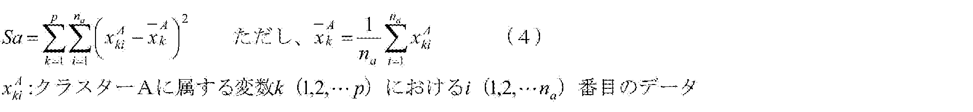

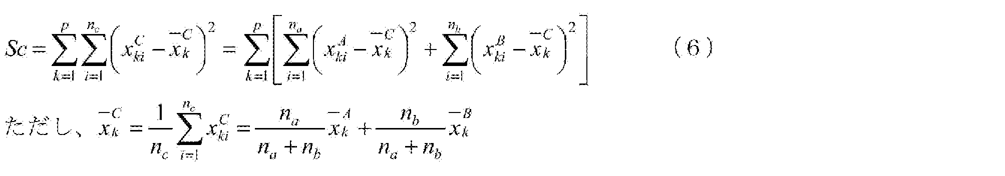
Next, the control device 8 applies the cluster analysis to the principal component scores shown in FIG. 5 to divide each lot into a plurality of groups (step S4). “Cluster analysis” is a method of classifying analysis target data (clusters) into a plurality of groups by focusing on similarity, and hierarchical clustering, classification optimization clustering, and the like are known. The “similarity” of interest in the cluster analysis in the present embodiment refers to the distance between the principal component scores of each lot. In the present embodiment, cohesive hierarchical clustering, which is one of hierarchical clustering, is used. In addition, as a method for calculating the distance between clusters, a Ward method that can stably obtain a solution was used. The “Ward method” is to select a cluster that minimizes the increase in the sum of squares of deviation when two clusters are merged. For example, when the clusters C are generated by merging the clusters A and B, the sums of squares of deviations Sa, Sb, and Sc in the clusters A, B, and C are represented by Equations 4 to 6, respectively.
数式4~6により、クラスターC内の偏差平方和Scは、以下のようになる。

From Equations 4 to 6, the sum of squares of deviation Sc in the cluster C is as follows.
数式7のΔSabは、クラスターA、Bを併合してクラスターCを生成した際の偏差平方和の増分であることを意味する。したがって、各併合段階でΔSabが最小になるようにクラスターを選択して併合することにより、クラスタリングを進めていく。
Δ ΔSab in equation 7 means the increment of the sum of squared deviations when clusters A and B are merged to generate cluster C. Therefore, clustering is advanced by selecting and merging clusters such that ΔSab is minimized at each merging stage.
本実施形態では、図5に示すように、第1~第5の固有ベクトルまでの5次元空間で6つのグループ1~6に区分した。なお、グループ1~6は、図5中のクラスター1~6にそれぞれ対応する。また、グループの数は、6つに眼定されるものではなく、ハンドリングし易い数であれば5つ以下でも7つ以上であっても構わない。
In the present embodiment, as shown in FIG. 5, the data is divided into six groups 1 to 6 in a five-dimensional space including first to fifth eigenvectors. Note that groups 1 to 6 correspond to clusters 1 to 6 in FIG. 5, respectively. The number of groups is not limited to six, and may be five or less or seven or more as long as the number is easy to handle.
同様にして、第2~第6の工程についても、主成分得点をグラフ上にプロットし、複数のグループに区分する。図6~10は、第2~第6の工程の製造条件について、主成分得点及びグループ(クラスター)を示すグラフである。
Similarly, in the second to sixth steps, the principal component scores are plotted on a graph and divided into a plurality of groups. 6 to 10 are graphs showing principal component scores and groups (clusters) for the manufacturing conditions in the second to sixth steps.
次に、第1~第6の工程における各グループの組み合わせ毎にロットの生成過程を複数のルートに区分する(ステップS5)。本実施形態では、過去の生産実績に基づいて16種類のルートが存在することが判明したため、16のルートに区分した。図11に、全ルートの内訳を示す。なお、図11における「Case」は、上述したルートに相当し、図11中の数字は、第1~第6の工程におけるグループの数字に対応する。また、図12に、ルートを構成するグループの組み合わせの例として、Case4~7に対応するルートを示す。
Next, the lot generation process is divided into a plurality of routes for each combination of the groups in the first to sixth steps (step S5). In the present embodiment, it has been found that there are 16 types of routes based on the past production results, and thus the routes are classified into 16 routes. FIG. 11 shows a breakdown of all routes. Note that “Case” in FIG. 11 corresponds to the above-described route, and the numbers in FIG. 11 correspond to the numbers of the groups in the first to sixth steps. FIG. 12 shows routes corresponding to Cases 4 to 7 as an example of combinations of groups constituting the routes.
次に、ルート毎にプロダクトデータの優劣を判定する(ステップS6)。このステップS6では、制御装置8は、プロダクトデータ(外観検査不良率等)から得られる中間変数を図11のCase1~16に属するロット毎に呼び出し、これらプロダクトデータの優劣を判定する。
Next, the superiority of the product data is determined for each route (step S6). In step S6, the control device 8 calls an intermediate variable obtained from the product data (such as the appearance inspection failure rate) for each lot belonging to Cases 1 to 16 in FIG. 11 and determines the superiority or inferiority of these product data.
なお、プロダクトデータの優劣は、ルート毎に区分された複数のロット(ロット群)内の平均値に基づいて行うのが好ましい。これにより、ルート内のロット群のプロダクトデータのばらつきが平準化され、ルート間のプロダクトデータの良否の傾向を大局的に把握することができる。
プ ロ ダ ク ト In addition, it is preferable that the superiority or inferiority of the product data is determined based on an average value in a plurality of lots (lot groups) divided for each route. As a result, the variation of the product data of the lot group in the route is leveled, and the tendency of the quality of the product data between the routes can be grasped globally.
また、プロダクトデータの優劣は、ルート内におけるプロダクトデータの偏差の大小や最大値及び最小値の差(範囲)の大小に基づいて判定しでも構わないし、平均値、偏差又はR値等を2つ以上組み合わせて判定しでも構わない。平均値と偏差とを組み合わせてプロダクトデータの優劣を判定するものとして、例えば、ルート内の平均値が同一の場合には、ルート内の偏差が小さいものを優と判断することが考えられる。これにより、ルート内でのプロダクトデータのばらつきを考慮したルート間のプロダクトデータの優劣の傾向を大局的に把握することができる。
The superiority of the product data may be determined based on the magnitude of the deviation of the product data in the route or the magnitude of the difference (range) between the maximum value and the minimum value, or two values such as an average value, a deviation, or an R value. The determination may be made in combination of the above. As an example of judging the superiority of the product data by combining the average value and the deviation, for example, when the average value in the route is the same, it is conceivable to determine the one with the smaller deviation in the route as superior. This makes it possible to globally grasp the tendency of the product data between routes taking into account the variation of the product data within the route.
そして、制御装置8は、ルート毎のプロダクトデータを比較してその優劣を決定する。図11では、各ルートにおけるプロダクトデータとしての外観検査不良率をそれらの優劣に応じて優、良、可の3段階で評価した。
{Circle around (5)} Then, the control device 8 compares the product data for each route and determines the superiority or inferiority. In FIG. 11, the failure rate of appearance inspection as product data in each route is evaluated in three levels of excellent, good, and acceptable according to their superiority.
次に、ルート毎のプロダクトデータの優劣に応じて、第1~第6の工程のグループの好適な組み合わせを特定する(ステップS7)。例えば、優と判定されたCase4、5と、良と判定されたCase6、7とを比較すると、これらは、第1、第2、第4、第6の工程は同ーのグループであるものの、第3の工程では異なるグループである。また、第5の工程はグループ1、2の何れであってもプロダクトデータには大きく影響しないものと推測される。すなわち、第1の工程のグループ2、第2の工程のグループ2を経たルートでは、第3の工程のグループ1を組み合わせることが好ましいと分かる。
Next, a suitable combination of the groups of the first to sixth steps is specified according to the superiority of the product data for each route (step S7). For example, comparing Cases 4 and 5 determined to be excellent with Cases 6 and 7 determined to be good, these are the same group in the first, second, fourth, and sixth steps, The third step is a different group. Further, it is assumed that the fifth step does not significantly affect the product data in any of groups 1 and 2. In other words, it can be seen that it is preferable to combine the third step group 1 with the route that has passed through the first step group 2 and the second step group 2.
また、優と判定されたCase14と、良と判定されたCase15とを比較すると、これらは、第1~第4、第6の工程は同ーのグループであるものの、第5の工程では異なるグループである。すなわち、第1の工程のグループ5、第2の工程のグループ3、第3の工程のグループ4、第4の工程のグループ2、第5の工程のグループ1、第6の工程のグループ1の組み合わせが好ましいことが分かる。なお、本実施形態における「好適な組み合わせ」とは、プロダクトデータの改善に寄与する組み合わせを意味するものであり、プロダクトデータが最も優れた組み合わせのみを意図するものではない。
In addition, a comparison between Case 14 determined to be excellent and Case 15 determined to be good indicates that although the first to fourth and sixth steps belong to the same group, they differ in the fifth step. It is. That is, group 5 of the first step, group 3 of the second step, group 4 of the third step, group 2 of the fourth step, group 1 of the fifth step, and group 1 of the sixth step It turns out that a combination is preferable. Note that the “suitable combination” in the present embodiment means a combination that contributes to the improvement of the product data, and does not intend only the combination having the best product data.
ステップS7で選定された組み合わせに基づいて、各工程の製造条件を設定する場合には、各グループのプロセスデータの平均値を製造条件の初期値に設定し、このときのプロダクトデータの良否を確認しながら製造条件を微調整するのが好ましい。プロセスデータの平均値を初期値に設定することにより、過去の状態を逸脱することなく、すなわち製造設備等に過度な負荷をかけることなく、第1~第6の工程のグループの好ましい組み合わせを再現することができる。
When setting the manufacturing conditions of each process based on the combination selected in step S7, the average value of the process data of each group is set to the initial value of the manufacturing conditions, and the quality of the product data at this time is checked. It is preferable to finely adjust the manufacturing conditions while doing so. By setting the average value of the process data to the initial value, a preferable combination of the first to sixth process groups can be reproduced without departing from the past state, that is, without imposing an excessive load on the manufacturing equipment. can do.
<本稼働段階>
次に、上記の準備段階で得られた基礎的な情報を基にして行われる制御装置8の処理を説明する。 <Production stage>
Next, the processing of thecontrol device 8 performed based on the basic information obtained in the above-described preparation stage will be described.
次に、上記の準備段階で得られた基礎的な情報を基にして行われる制御装置8の処理を説明する。 <Production stage>
Next, the processing of the
連続生産システム1では、粉状の原料が混合機2に投入されると、原料の粉や液体の混合が混合機2において行われ、混合機2で混合された原料を小粒子群に結着させて粒状にする処理が造粒機3において行われ、造粒機3で造粒された原料の乾燥が乾燥機4において行われ、乾燥機4で乾燥された原料の混合が混合機5において行われ、混合機5で混合された原料を圧縮して錠剤にする処理が打錠機6において行われ、当該錠剤にコーティングを施す処理がコーティング機7において行われる。制御装置8は、混合機2からコーティング機7へ至る一連の機器が適切に動作するよう、各機器の制御目標値の変更や経路の途中に設けられた弁の切替処理を実行する。その際、制御装置8は、上記の準備段階で得られた基礎的な情報を基に、各機器の制御目標値の変更や経路の途中に設けられた弁の切替処理を実行する。
In the continuous production system 1, when a powdery raw material is put into the mixer 2, mixing of powder and liquid of the raw material is performed in the mixer 2, and the raw material mixed by the mixer 2 is bound to a small particle group. The granulating process is performed in the granulator 3, the raw material granulated by the granulator 3 is dried in the dryer 4, and the raw material dried in the dryer 4 is mixed in the mixer 5. The process of compressing the raw materials mixed by the mixer 5 into tablets is performed in the tableting machine 6, and the process of coating the tablets is performed in the coating machine 7. The control device 8 executes a process of changing the control target value of each device and a process of switching a valve provided in the middle of the path so that a series of devices from the mixer 2 to the coating machine 7 operate properly. At that time, the control device 8 executes a process of changing the control target value of each device and a process of switching a valve provided in the middle of the path based on the basic information obtained in the above-described preparation stage.
図13は、制御装置8で行われる処理の一例を示した図である。連続生産システム1の各設備が稼働すると、制御装置8では、図13に示される処理フローが実行される。すなわち、連続生産システム1の各設備が稼働すると、制御装置8は、各工程の現在の製造条件の情報を取得する(S11)。そして、制御装置8は、準備段階で作成された複数のルートのうち何れかのルートを選択する(S12)。ルートの選択は、取得した現在の製造条件の情報を基にして行われる。連続生産システム1では、連続生産システム1において実現されるプロセスのうち最初の工程を担うのは混合機2であるため、制御装置8は、混合機2から取得された現在の製造条件の情報を基にしてルートの選択を行う。
FIG. 13 is a diagram illustrating an example of a process performed by the control device 8. When each facility of the continuous production system 1 operates, the control device 8 executes the processing flow shown in FIG. That is, when each facility of the continuous production system 1 operates, the control device 8 acquires information on current manufacturing conditions of each process (S11). Then, the control device 8 selects any one of the plurality of routes created in the preparation stage (S12). The selection of the route is performed based on the acquired information on the current manufacturing conditions. In the continuous production system 1, the first step in the processes realized in the continuous production system 1 is performed by the mixer 2. Therefore, the control device 8 transmits the information on the current manufacturing conditions acquired from the mixer 2. Make a route selection based on that.
例えば、図11に示した16のルートが準備段階で用意されており、第1の工程を担う混合機2から取得された製造条件がグループ5に属するものであった場合、制御装置8は、グループ5が採り得る2つのルート(Case14~15)のうち最終製品の品質が比較的良好なCase14のルートを選択する。
For example, when 16 routes shown in FIG. 11 are prepared in the preparation stage, and the manufacturing conditions acquired from the mixer 2 that performs the first process belong to the group 5, the control device 8 From among the two routes (Cases 14 to 15) that can be taken by the group 5, the route of Case 14 in which the quality of the final product is relatively good is selected.
そして、制御装置8は、ルートの選択を行った後、選択したルートに沿った製造条件となるように連続生産システム1の各機器の制御目標値を設定する(S13)。制御装置8が各機器の制御目標値を設定することにより、連続生産システム1の各機器では、制御装置8が設定した制御目標値に沿った動作が行われる。
Then, after selecting the route, the control device 8 sets the control target value of each device of the continuous production system 1 so that the manufacturing conditions are along the selected route (S13). By the control device 8 setting the control target value of each device, each device of the continuous production system 1 performs an operation according to the control target value set by the control device 8.
例えば、ステップS12でCase14のルートが選択された場合、制御装置8は、各工程を担う連続生産システム1の各機器の制御目標値が、図11に示されたCase14の場合における各工程の既定の製造条件となるように、ステップS13において各機器に対する制御目標値の設定を行う。これにより、連続生産システム1の各機器では、制御装置8が設定した制御目標値に沿った動作が行われる。そして、特段の異常が無ければ、図12において特定のルートで示されるような既定の製造条件を各ロットが辿ることになる。
For example, when the route of Case 14 is selected in step S12, the control device 8 sets the control target value of each device of the continuous production system 1 that performs each process to the default value of each process in the case of Case 14 illustrated in FIG. In step S13, a control target value for each device is set so that the manufacturing conditions are satisfied. Thereby, each device of the continuous production system 1 performs an operation according to the control target value set by the control device 8. If there is no particular abnormality, each lot follows predetermined manufacturing conditions as indicated by a specific route in FIG.
そこで、制御装置8は、各ロットが特段の異常無く予定のルートを辿っていることを監視するために、各工程における現在の製造条件を取得する処理(S14)と、取得した現在の製造条件が、ステップS12で選択したルートで既定されている製造条件に沿っているか否かを判定する処理(S15)とを実行する。そして、制御装置8は、ステップS15で否定判定を行った場合、ステップS12で選択したルートを変更するか否かを判定する処理(S16)を実行する。
In order to monitor that each lot follows a scheduled route without any particular abnormality, the controller 8 acquires the current manufacturing conditions in each process (S14), and acquires the current manufacturing conditions in each process. (S15) to determine whether or not the manufacturing conditions specified by the route selected in step S12 are being met. Then, when a negative determination is made in step S15, the control device 8 executes a process (S16) of determining whether to change the route selected in step S12.
なお、ステップS15の判定処理は、例えば、図12において各ルートに既定される製造条件に対し、許容される製造条件の差分が各々設定されており、ステップS14で取得した現在の製造条件が差分の範囲内にあるか否かに応じて行われるものであってもよいし、或いは、図12において各ルートに既定される製造条件が予め上限値と下限値とを既定するものであり、ステップS14で取得した現在の製造条件が上限値と下限値との間にあるか否かに応じて行われるものであってもよい。
In the determination process in step S15, for example, the difference between the allowable manufacturing conditions is set for each of the manufacturing conditions specified for each route in FIG. 12, and the current manufacturing condition acquired in step S14 is set to the difference. May be performed depending on whether or not it is within the range, or the manufacturing conditions defined for each route in FIG. 12 may define an upper limit value and a lower limit value in advance. The process may be performed depending on whether or not the current manufacturing condition acquired in S14 is between the upper limit value and the lower limit value.
また、ステップS16の判定処理は、例えば、現在の製造条件がルートを逸脱していることをオペレータに対して通知し、当該オペレータに対しルート変更の可否の判断を要求するものであってもよいし、或いは、図12に示したような複数あるルートの情報を制御装置8が参照し、ステップS12で選択したルートとは異なる他の代替ルートがあるか否かによって判定するものであってもよい。
In addition, the determination process of step S16 may be, for example, a process in which an operator is notified that the current manufacturing conditions deviate from the route, and the operator is required to determine whether or not the route can be changed. Alternatively, the control device 8 refers to information on a plurality of routes as shown in FIG. 12 and determines whether there is another alternative route different from the route selected in step S12. Good.
連続生産システム1の各設備が稼働している間、制御装置8によって上記一連の処理が実行されることにより、過去の生産実績によって品質を維持できることが既に確認された幾つかのルートの製造条件に沿うように各ロットへの処理が行われる。すなわち、連続生産システム1では、制御装置8による上記処理が実行されることにより、過去の生産実績を基にした最適な制御目標値の設定が現在の製造状態に応じて行われるため、例えば、従来行われているような、製造状態に関わり無く一律に固定の制御目標値を各機器に設定する場合に比べると、製品の品質をより安定化させることができる。
While the respective facilities of the continuous production system 1 are operating, the above-described series of processing is executed by the control device 8, and the production conditions of some routes that have already been confirmed to be able to maintain quality by past production results Is performed for each lot so as to meet the requirements. That is, in the continuous production system 1, by executing the above-described processing by the control device 8, the optimal control target value based on the past production results is set according to the current production state. The quality of the product can be further stabilized as compared with a case where a fixed control target value is uniformly set for each device regardless of the manufacturing state as conventionally performed.
なお、連続生産システム1では、医薬品である錠剤を粉状の原料から連続的に生産するシステムであるため、ステップS15で肯定判定が行われた場合に、該当するロットが次工程へ流れるのを防止する処理を行うようにしてもよい。特定のロットが次工程へ流れるのを防止する処理は、例えば、連続生産システム1の適宜の箇所に配置された検査選別装置10を以下のように用いることで実現可能である。以下、検査選別装置10が図1の符号Cに設置された場合に連続生産システム1で実現可能となる全体の制御フローの一例について説明する。
Since the continuous production system 1 is a system for continuously producing tablets, which are pharmaceuticals, from powdery raw materials, if a positive determination is made in step S15, the corresponding lot flows to the next process. Preventive processing may be performed. The process of preventing a specific lot from flowing to the next process can be realized, for example, by using the inspection and sorting device 10 arranged at an appropriate place in the continuous production system 1 as follows. Hereinafter, an example of an entire control flow that can be realized by the continuous production system 1 when the inspection and sorting device 10 is installed at reference numeral C in FIG. 1 will be described.
図1に示した連続生産システム1の乾燥機4では、造粒機3で造粒された原料に各種の追加原料が加えられて乾燥が行われる。乾燥機4には、加熱乾燥を行うための1以上のヒータが設けられており、適切な乾燥温度となるようにヒータの通電量が制御装置8で調整される。また、乾燥機4には、可変速のブロワーが設けられており、造粒機3で造粒された原料が乾燥機4内を適切な風速で通過するようにブロワーの回転速度が制御装置8で調整される。
で は In the dryer 4 of the continuous production system 1 shown in FIG. 1, various additional raw materials are added to the raw material granulated by the granulator 3 and drying is performed. The dryer 4 is provided with one or more heaters for performing heating and drying, and the control device 8 adjusts the amount of current supplied to the heaters so as to obtain an appropriate drying temperature. The dryer 4 is provided with a variable speed blower, and the rotation speed of the blower is controlled by the controller 8 so that the raw material granulated by the granulator 3 passes through the dryer 4 at an appropriate wind speed. It is adjusted by.
ここで、乾燥機4と混合機5を繋ぐ経路の途中、すなわち、図1の符号Cに示される部位に上記の検査選別装置10が設置されていれば、乾燥機4における製造条件がルートから逸脱した場合に、連続的に処理される原料が、次工程を担う混合機5へ流れるのを防止することができる。よって、当該原料を混合機5以外の機器へ移送して適切な処理を施したり、或いは、連続生産システム1の系外へ排出したりすることが可能となる。
Here, if the above-described inspection and sorting device 10 is installed in the middle of the path connecting the dryer 4 and the mixer 5, that is, at the site indicated by the symbol C in FIG. In the case of deviation, it is possible to prevent the raw material to be continuously processed from flowing to the mixer 5 which is responsible for the next step. Therefore, it is possible to transfer the raw material to equipment other than the mixer 5 to perform appropriate processing, or to discharge the raw material to the outside of the continuous production system 1.
<変形例>
以下、上記実施形態の変形例について説明する。上記実施形態では、本稼働段階におけるルートの選択が、第1の工程を担う混合機2から取得された製造条件の情報を用いて行われていたが、連続生産システム1は、例えば、原料の特性を基にしてルートの選択を行うようにしてもよい。以下、本変形例の詳細について説明する。 <Modification>
Hereinafter, a modified example of the above embodiment will be described. In the above-described embodiment, the selection of the route in the actual operation stage is performed using the information on the manufacturing conditions acquired from themixer 2 that performs the first process. The route may be selected based on the characteristics. Hereinafter, details of the present modified example will be described.
以下、上記実施形態の変形例について説明する。上記実施形態では、本稼働段階におけるルートの選択が、第1の工程を担う混合機2から取得された製造条件の情報を用いて行われていたが、連続生産システム1は、例えば、原料の特性を基にしてルートの選択を行うようにしてもよい。以下、本変形例の詳細について説明する。 <Modification>
Hereinafter, a modified example of the above embodiment will be described. In the above-described embodiment, the selection of the route in the actual operation stage is performed using the information on the manufacturing conditions acquired from the
本変形例のハードウェア構成は、基本的に上記実施形態の連続生産システム1と同様であるため、上記実施形態の連続生産システム1と同一の符号を用いて説明することとし、各機器の詳細な説明については省略する。また、本変形例も上記実施形態と同様、原料の粉体から製品を連続生産する場合を例に説明するが、例えば、各工程を担う装置間で原料が容器等により間欠的に移動されるバッチ式にも適用可能である。また、本変形例では、医薬品を製造する場合を例に説明するが、例えば、食品やその他各種製品の製造にも適用可能である。
Since the hardware configuration of this modification is basically the same as that of the continuous production system 1 of the above embodiment, it will be described using the same reference numerals as those of the continuous production system 1 of the above embodiment, and details of each device will be described. Detailed description is omitted. Also, in the present modification, similarly to the above-described embodiment, a case in which a product is continuously produced from a raw material powder will be described as an example. For example, the raw material is intermittently moved by a container or the like between apparatuses performing each process. It is also applicable to a batch type. Further, in the present modified example, a case where a pharmaceutical is manufactured will be described as an example, but the present invention is also applicable to the manufacture of food and other various products.
<処理フロー>
以下、本変形例において制御装置8によって実現される連続生産システム1の動作内容について説明する。本変形例においても、上記実施形態と同様、制御装置8によって実現される連続生産システム1の動作内容の説明は、主に、準備段階の内容と本稼働段階の内容とに大別される。そこで、まず、準備段階の内容の説明を行った後、本稼働段階の内容の説明を行う。 <Processing flow>
Hereinafter, the operation of thecontinuous production system 1 realized by the control device 8 in the present modified example will be described. Also in the present modified example, as in the above embodiment, the description of the operation content of the continuous production system 1 realized by the control device 8 is mainly divided into the content of the preparation stage and the content of the main operation stage. Therefore, first, the contents of the preparation stage will be described, and then the contents of the main operation stage will be described.
以下、本変形例において制御装置8によって実現される連続生産システム1の動作内容について説明する。本変形例においても、上記実施形態と同様、制御装置8によって実現される連続生産システム1の動作内容の説明は、主に、準備段階の内容と本稼働段階の内容とに大別される。そこで、まず、準備段階の内容の説明を行った後、本稼働段階の内容の説明を行う。 <Processing flow>
Hereinafter, the operation of the
<準備段階>
本変形例における生産プロセスの解析方法の手順を、図4に示すフローチャートを用いて説明する。 <Preparation stage>
The procedure of the production process analysis method according to the present modification will be described with reference to the flowchart shown in FIG.
本変形例における生産プロセスの解析方法の手順を、図4に示すフローチャートを用いて説明する。 <Preparation stage>
The procedure of the production process analysis method according to the present modification will be described with reference to the flowchart shown in FIG.
上記実施形態と同様、まず、動作済みの生産プロセスについて、制御装置8は、製造条件の情報(プロセスデータとプロダクトデータ)を収集する(ステップS1)。この際、上記実施形態では、センサが測定した製造条件の情報を収集していたが、本変形例では、センサが測定したプロセスデータの他に、原料データ(原料の物性、組成等)についても収集される。原料データは、例えば、原料メーカーから提供される。
{Circle around (1)} As in the above embodiment, first, the control device 8 collects information on the manufacturing conditions (process data and product data) for the operated production process (step S1). At this time, in the above embodiment, the information on the manufacturing conditions measured by the sensor is collected. However, in this modification, in addition to the process data measured by the sensor, the raw material data (physical properties, composition, and the like of the raw material) are also obtained. Collected. The raw material data is provided from, for example, a raw material maker.
そして、本変形例の制御装置8では、上記実施形態と同様、データを標準化する処理(ステップS2)や、中間変数に基づいて主成分負荷量及び主成分得点を求める処理(ステップS3)、各ロットを複数のグループに区分する処理(ステップS4)、各グループの組み合わせ毎にロットの生成過程を複数のルートに区分する処理(ステップS5)、ルート毎にプロダクトデータの優劣を判定する処理(ステップS6)、グループの好適な組み合わせを特定する処理(ステップS7)が行われる。
Then, in the control device 8 of this modified example, similarly to the above embodiment, a process of standardizing data (step S2) and a process of calculating a principal component load and a principal component score based on intermediate variables (step S3) Processing for dividing a lot into a plurality of groups (step S4), processing for dividing a lot generation process into a plurality of routes for each combination of groups (step S5), and processing for judging the superiority of product data for each route (step S5) S6), a process of specifying a suitable combination of groups (step S7) is performed.
例えば、ステップS2においては、既述した数式1に基づいたデータの標準化処理が行われる。また、ステップS3においては、中間変数における相関係数行列の作成や、相関係数行列の固有値と固有ベクトルの導出が行われた後、相関係数行列の固有ベクトルから主成分得点が求められ、相関係数行列の固有値から各主成分の寄与率が求められる。また、ステップS4においては、主成分得点にクラスター分析を適用して、各ロットを複数のグループに区分する処理が行われる。そして、ステップS5の処理が行われた後のステップS6においては、プロダクトデータ(外観検査不良率等)から得られる中間変数をロット毎に呼び出し、これらプロダクトデータの優劣を判定することにより、ルート毎のプロダクトデータの優劣の判定が行われる。また、ステップS7においては、ルート毎のプロダクトデータの優劣を比較することにより、品質が比較的良好となる各工程のグループの組み合わせが特定される。
{For example, in step S2, data standardization processing based on the above-described formula 1 is performed. Further, in step S3, after the creation of the correlation coefficient matrix for the intermediate variables and the derivation of the eigenvalues and eigenvectors of the correlation coefficient matrix, a principal component score is obtained from the eigenvectors of the correlation coefficient matrix. The contribution ratio of each principal component is obtained from the eigenvalues of the numerical matrix. In step S4, a process of applying a cluster analysis to the principal component scores to divide each lot into a plurality of groups is performed. Then, in step S6 after the processing in step S5, the intermediate variables obtained from the product data (such as the appearance inspection failure rate) are called for each lot, and the superiority or inferiority of these product data is determined, so that each route is determined. Of product data is judged. Further, in step S7, by comparing the superiority and the inferiority of the product data for each route, the combination of the groups of the respective processes whose quality is relatively good is specified.
図14は、特性に応じて複数のグループに分類された原料の一例を示した図である。粉体等の各種原料には、特定のメーカーから仕入れた同一の製品であっても、図14に示されるように、ロットによって特性に多少のばらつきがある。そこで、本変形例では、このような原料の特性に関する情報を原料データとして生産プロセスの解析に取り込んでいる。よって、過去の生産実績に基づく生産プロセスの解析を行うと、最終製品の品質が比較的良好となるルートが原料特性に応じて幾つか存在する場合が生じる。
FIG. 14 is a diagram showing an example of raw materials classified into a plurality of groups according to characteristics. As shown in FIG. 14, various raw materials such as powders have some variation in characteristics depending on lots, even for the same product purchased from a specific manufacturer. Therefore, in this modification, such information on the characteristics of the raw material is incorporated into the analysis of the production process as raw material data. Therefore, when a production process is analyzed based on past production results, there may be cases where there are some routes according to the raw material characteristics, in which the quality of the final product is relatively good.
図15は、原料データを生産プロセスの解析に取り込んだ場合に出現するルートの一例を示した図である。粉体等の各種原料には、ロットによって特性に多少のばらつきがあるため、原料データを標準化して中間変数に変換し、主成分得点を求めると、主成分得点をプロットした図15の「原料特性」のグラフにも示されるように、原料特性のばらつきがグラフ上に出現する。本変形例では、原料特性のばらつきを示す主成分得点にクラスター分析を適用して、各原料を複数のグループに区分する処理が行われる。
FIG. 15 is a diagram showing an example of a route that appears when the raw material data is taken into the analysis of the production process. Since the characteristics of various raw materials such as powders vary slightly depending on the lot, the raw material data is standardized and converted into intermediate variables, and the principal component score is obtained. As shown in the “Characteristics” graph, variations in the raw material characteristics appear on the graph. In the present modification, a process is performed in which each raw material is divided into a plurality of groups by applying cluster analysis to the principal component scores indicating variations in raw material characteristics.
また、本変形例では、各原料を複数のグループに区分する処理の他に、各工程についても主成分得点を複数のグループに区分する処理が行われる。図15の「第1工程」から「第n工程」までに示される幾つかのグラフは、各工程の製造条件について、主成分得点及びグループ(クラスター)を示したグラフである。
In addition, in this modification, in addition to the process of dividing each raw material into a plurality of groups, the process of dividing the principal component score into a plurality of groups is also performed in each step. Some graphs shown from “first step” to “n-th step” in FIG. 15 are graphs showing principal component scores and groups (clusters) for the manufacturing conditions of each step.
そして、本変形例では、原料特性及び各工程における各グループの組み合わせ毎にロットの生成過程を複数のルートに区分する処理が行われた後、ルート毎にプロダクトデータの優劣の判定が行われ、図15に示されるように、原料特性を起点とした幾つかのルートが抽出される。
Then, in the present modification, after the process of dividing the lot generation process into a plurality of routes is performed for each combination of the raw material characteristics and each group in each process, the superiority of the product data is determined for each route, As shown in FIG. 15, several routes starting from the raw material characteristics are extracted.
<本稼働段階>
次に、上記の準備段階で得られた基礎的な情報を基にして本変形例における制御装置8で行われる処理を説明する。なお、本変形例における制御装置8で行われる処理は、基本的には上記実施形態の場合と同様であるため、上記実施形態との相違点を中心に説明する。 <Production stage>
Next, a process performed by thecontrol device 8 in the present modified example based on the basic information obtained in the above-described preparation stage will be described. Note that the processing performed by the control device 8 in this modified example is basically the same as that in the above-described embodiment, and therefore a description will be given focusing on differences from the above-described embodiment.
次に、上記の準備段階で得られた基礎的な情報を基にして本変形例における制御装置8で行われる処理を説明する。なお、本変形例における制御装置8で行われる処理は、基本的には上記実施形態の場合と同様であるため、上記実施形態との相違点を中心に説明する。 <Production stage>
Next, a process performed by the
本変形例の制御装置8では、連続生産システム1の各設備が稼働すると、図13に示されたのと同等の処理フローが実行される。すなわち、連続生産システム1の各設備が稼働すると、制御装置8は、製造条件を取得する(S11)。この際、制御装置8は、原料データを製造条件として取得する。原料データは、例えば、オペレータの操作により入力される。そして、制御装置8は、準備段階で作成された複数のルートのうち何れかのルートを選択する(S12)。ルートの選択は、取得した原料データを基にして行われる。そして、制御装置8は、ルートの選択を行った後、選択したルートに沿った製造条件となるように連続生産システム1の各機器の制御目標値を設定する(S13)。これにより、連続生産システム1の各機器では、制御装置8が設定した制御目標値に沿った動作が行われ、特段の異常が無ければ、図16に示されるように、選択された予定のルートを現在のロットが辿ることになる。選択された予定のルートを現在のロットが辿っていることの確認は、各工程における現在の製造条件の情報を取得する処理(S14)と、取得した現在の製造条件が、ステップS12で選択したルートで既定されている製造条件に沿っているか否かを判定する処理(S15)とによって行われる。
In the control device 8 of this modification, when each facility of the continuous production system 1 operates, a processing flow equivalent to that shown in FIG. 13 is executed. That is, when each facility of the continuous production system 1 operates, the control device 8 acquires the manufacturing conditions (S11). At this time, the control device 8 acquires raw material data as manufacturing conditions. The raw material data is input, for example, by an operation of an operator. Then, the control device 8 selects any one of the plurality of routes created in the preparation stage (S12). The route is selected based on the acquired raw material data. Then, after selecting the route, the control device 8 sets the control target value of each device of the continuous production system 1 so that the manufacturing conditions are along the selected route (S13). Thereby, in each device of the continuous production system 1, the operation according to the control target value set by the control device 8 is performed, and if there is no special abnormality, as shown in FIG. Will be traced by the current lot. To confirm that the current lot is following the selected scheduled route, the process of acquiring the information on the current manufacturing conditions in each process (S14) and the obtained current manufacturing conditions are selected in step S12. The process (S15) of determining whether or not the manufacturing condition is set according to the route is determined.
ここで、図17に示されるように、選択された予定のルートを現在のロットが外れた場合、ステップS15では否定判定が行われる。そして、ステップS12で選択したルートを変更するか否かを判定する処理(S16)が実行される。
Here, as shown in FIG. 17, when the current lot deviates from the selected scheduled route, a negative determination is made in step S15. Then, a process (S16) of determining whether to change the route selected in step S12 is executed.
連続生産システム1の各設備が稼働している間、本変形例の制御装置8によって上記一連の処理が実行されることにより、連続生産システム1に投入された原料の特性に応じて、過去の生産実績によって品質を維持できることが既に確認された幾つかのルートの製造条件に沿うように各ロットへの処理が行われる。よって、例えば、原料の特性や製造状態に関わり無く一律に固定の制御目標値を各機器に設定する場合に比べると、製品の品質をより安定化させることができる。
While the equipment of the continuous production system 1 is operating, the above-described series of processing is executed by the control device 8 of the present modified example. Each lot is processed so as to meet the manufacturing conditions of some routes for which it has been confirmed that the quality can be maintained by the production results. Therefore, for example, the quality of the product can be further stabilized as compared with a case where a fixed control target value is uniformly set for each device regardless of the characteristics of the raw materials and the manufacturing state.
なお、特定のロットが次工程へ流れるのを防止する処理については、前述の実施形態の説明と同様に本変形例へ適用可能である。
Note that the process of preventing a specific lot from flowing to the next process can be applied to the present modified example as in the description of the above-described embodiment.
1・・連続生産システム
2・・混合機
3・・造粒機
4・・乾燥機
5・・混合機
6・・打錠機
7・・コーティング機
8・・制御装置
10・・検査選別装置
11・・流入経路
12・・入口側仕切弁
13・・エアー吹込み経路
14・・サイトグラス
15,24・・レーザーセンサ
16・・検査室
17・・分光分析計
18・・出口側仕切弁
19,20・・弁孔
21・・流路切替弁
22,23・・流出経路 1.Continuous production system 2. Mixer 3. Granulator 4. Dryer 5. Mixer 6. Tableting machine 7. Coating machine 8. Control device 10. Inspection / sorting device 11. ··· Inflow path 12 ··· Inlet gate valve 13 ··· Air blowing path 14 ··· Sight glass 15 and 24 ··· Laser sensor 16 ··· Inspection room 17 · · · Spectrometer 18 · · · Exit side gate valve 19 20, valve hole 21, flow path switching valve 22, 23, outflow path
2・・混合機
3・・造粒機
4・・乾燥機
5・・混合機
6・・打錠機
7・・コーティング機
8・・制御装置
10・・検査選別装置
11・・流入経路
12・・入口側仕切弁
13・・エアー吹込み経路
14・・サイトグラス
15,24・・レーザーセンサ
16・・検査室
17・・分光分析計
18・・出口側仕切弁
19,20・・弁孔
21・・流路切替弁
22,23・・流出経路 1.
Claims (10)
- 複数の工程を有する生産プロセスによって、原料から製品を生産する生産システムであって、
前記工程を担う複数の生産設備と、
前記複数の生産設備に各々設定される制御目標値を決定する制御装置と、を備え、
前記制御装置は、前記生産プロセスに投入される原料の特性の情報を取得すると、一種以上の原料における複数項目の特性の組み合わせからなる原料特性毎に区分された複数のグループに各々設定されるルートであり、各工程において製造条件毎に区分された複数のグループの工程間における組み合わせ毎に区分された各ロットの品質項目に基づいて優劣が判定された、前記各ロットが前記生産プロセスを経る際に辿った製造条件のルートの優劣に応じて特定された前記グループの組み合わせの情報を参照し、前記複数の生産設備のうち少なくとも何れかに設定される制御目標値を決定する、
生産システム。 A production system that produces products from raw materials by a production process having a plurality of steps,
A plurality of production facilities for carrying out the process,
A control device that determines a control target value that is set for each of the plurality of production facilities,
When the control device obtains information on the characteristics of the raw materials to be input to the production process, routes set in a plurality of groups that are divided for each of the raw material characteristics including a combination of characteristics of a plurality of items in one or more raw materials. When each lot goes through the production process, the superiority or the inferiority is determined based on the quality item of each lot divided for each combination among a plurality of groups of steps divided for each manufacturing condition in each step. Referring to the information of the combination of the groups specified according to the superiority of the route of the manufacturing conditions followed to determine a control target value set to at least one of the plurality of production equipment,
Production system. - 前記制御装置は、前記グループの組み合わせのうち少なくとも製品の品質の条件が満たされる何れかの組み合わせの情報を参照し、前記複数の生産設備のうち少なくとも何れかに設定される制御目標値を決定する、
請求項1に記載の生産システム。 The control device refers to information on any combination that satisfies at least the condition of product quality among the combinations of the groups, and determines a control target value set in at least one of the plurality of production facilities. ,
The production system according to claim 1. - 前記制御装置は、決定した制御目標値を前記複数の生産設備のうち少なくとも何れかに設定する、
請求項1または2に記載の生産システム。 The control device sets the determined control target value in at least one of the plurality of production facilities,
The production system according to claim 1. - 前記制御装置は、前記生産プロセスで前記製品が生産されている状態において、前記複数の工程のうち少なくとも何れかの工程の状態を示す製造条件の情報を取得すると、取得した情報を基に、前記製品のロットが前記ルートの製造条件に沿っているか否かの判定を行う、
請求項1から3の何れか一項に記載の生産システム。 The control device, in a state where the product is being produced in the production process, when acquiring information on manufacturing conditions indicating a state of at least one of the plurality of steps, based on the acquired information, Determine whether the product lot is in line with the manufacturing conditions of the route,
The production system according to claim 1. - 前記組み合わせの情報は、前記工程毎の状態を示す製造条件及び前記製品の品質を示す品質項目を含むデータを前記生産プロセスのロット毎に収集し、前記工程の製造条件に応じて各工程を複数のグループに区分し、前記グループの組み合わせ毎に前記ロットを複数のルートに区分し、前記ルートの品質項目に応じて前記ルートの優劣を判定し、前記ルートの優劣に応じて特定された前記グループの好適な組み合わせの情報である、
請求項1から4の何れか一項に記載の生産システム。 The combination information is obtained by collecting, for each lot of the production process, data including a manufacturing condition indicating a state of each process and a quality item indicating a quality of the product, and a plurality of processes according to the manufacturing conditions of the process. The lot is divided into a plurality of routes for each combination of the groups, the superiority of the route is determined according to the quality item of the route, and the group specified according to the superiority of the route is determined. Information of a suitable combination of
The production system according to claim 1. - 前記生産プロセスは、原料の粉体から製品を連続生産する連続生産プロセスであり、
前記複数の生産設備は、原料の粉体に第1の処理を行う第1処理装置と、前記第1処理装置が前記第1の処理を行った粉体へ第2の処理を行う第2処理装置と、前記第1処理装置から送られた粉体が流入する検査室を有する検査選別装置と、を有し、
前記検査選別装置は、前記検査室に所定量の粉体が溜まると、前記第1処理装置から前記検査室へ繋がる経路を閉鎖した後に前記検査室内の粉体の検査を実行し、前記検査を終えると、前記検査室内から粉体を排出した後に前記閉鎖を解除する装置であり、
前記制御装置は、前記検査選別装置で前記検査室内の粉体の特性の情報を取得すると、前記組み合わせの情報を参照し、前記第2処理装置に設定される制御目標値を決定する、
請求項1から5の何れか一項に記載の生産システム。 The production process is a continuous production process for continuously producing a product from raw material powder,
The plurality of production facilities include a first processing apparatus that performs a first processing on the raw material powder, and a second processing that performs a second processing on the powder that has been subjected to the first processing by the first processing apparatus. An apparatus and an inspection and sorting apparatus having an inspection room into which the powder sent from the first processing apparatus flows,
When a predetermined amount of powder accumulates in the inspection room, the inspection and sorting device closes a path leading from the first processing device to the inspection room, executes inspection of the powder in the inspection room, and performs the inspection. When finished, is a device for releasing the closure after discharging the powder from the inspection room,
The control device, when acquiring the information on the characteristics of the powder in the inspection chamber by the inspection and sorting device, refers to the information on the combination, and determines a control target value to be set in the second processing device.
The production system according to claim 1. - 前記制御装置は、前記組み合わせの情報を参照した結果、前記検査室内の粉体が前記何れのグループにも区分されない場合、前記検査選別装置に前記検査室内の粉体を前記第2処理装置へ排出させない、
請求項6に記載の生産システム。 As a result of referring to the information of the combination, if the powder in the inspection room is not classified into any of the groups, the control device discharges the powder in the inspection room to the inspection and sorting device to the second processing device. Don't let me
The production system according to claim 6. - 複数の工程を有する生産プロセスによって、原料から製品を生産する生産方法であって、
前記工程を担う複数の生産設備を作動させる工程と、
前記複数の生産設備に各々設定される制御目標値を制御装置に決定させる工程と、を有し、
前記制御装置に決定させる工程では、前記生産プロセスに投入される原料の特性の情報を取得すると、一種以上の原料における複数項目の特性の組み合わせからなる原料特性毎に区分された複数のグループに各々設定されるルートであり、各工程において製造条件毎に区分された複数のグループの工程間における組み合わせ毎に区分された各ロットの品質項目に基づいて優劣が判定された、前記各ロットが前記生産プロセスを経る際に辿った製造条件のルートの優劣に応じて特定された前記グループの組み合わせの情報を参照し、前記複数の生産設備のうち少なくとも何れかに設定される制御目標値を決定する、
生産方法。 A production method for producing a product from raw materials by a production process having a plurality of steps,
Activating a plurality of production facilities responsible for the process,
Causing a control device to determine a control target value set for each of the plurality of production facilities,
In the step of allowing the control device to determine, when acquiring information on the characteristics of the raw materials to be input to the production process, each of the plurality of groups is divided into a plurality of groups each classified as a raw material characteristic including a combination of characteristics of a plurality of items in one or more raw materials. A route to be set, wherein each lot is determined to be superior or inferior based on a quality item of each lot classified for each combination among a plurality of groups of processes classified for each manufacturing condition in each process. Referring to the information of the combination of the groups specified according to the superiority of the route of the manufacturing conditions followed during the process, to determine a control target value set to at least one of the plurality of production equipment,
Production method. - 複数の工程を有する生産プロセスによって、原料から製品を生産する生産システムの制御装置であって、
前記工程を担う複数の生産設備に各々設定される制御目標値を決定する処理を実行する処理部と、
前記処理部が決定した制御目標値を出力する出力部と、を備え、
前記処理部は、前記生産プロセスに投入される原料の特性の情報を取得すると、一種以上の原料における複数項目の特性の組み合わせからなる原料特性毎に区分された複数のグループに各々設定されるルートであり、各工程において製造条件毎に区分された複数のグループの工程間における組み合わせ毎に区分された各ロットの品質項目に基づいて優劣が判定された、前記各ロットが前記生産プロセスを経る際に辿った製造条件のルートの優劣に応じて特定された前記グループの組み合わせの情報を参照し、前記複数の生産設備のうち少なくとも何れかに設定される制御目標値を決定する、
制御装置。 A control device for a production system that produces a product from raw materials by a production process having a plurality of steps,
A processing unit that performs a process of determining a control target value that is set for each of a plurality of production facilities that perform the process,
An output unit that outputs the control target value determined by the processing unit,
When the processing unit obtains information on the characteristics of the raw materials supplied to the production process, routes set in a plurality of groups classified for each raw material characteristic composed of a combination of characteristics of a plurality of items of one or more raw materials are set. When each lot goes through the production process, the superiority or the inferiority is determined based on the quality item of each lot divided for each combination among a plurality of groups of steps divided for each manufacturing condition in each step. Referring to the information of the combination of the groups specified according to the superiority of the route of the manufacturing conditions followed to determine a control target value set to at least one of the plurality of production equipment,
Control device. - 複数の工程で構成され、原料から製品を生産する生産プロセスの解析方法であって、
前記生産プロセスに投入される原料の特性の情報と、前記複数の工程のうち少なくとも何れかの工程の状態を示す製造条件の情報とを、前記生産プロセスのロット毎に取得するステップと、
前記原料の特性及び前記工程の製造条件に応じて、前記原料を一種以上の原料における複数項目の特性の組み合わせからなる原料特性毎のグループ、及び、各工程を複数のグループに区分するステップと、
前記グループの組み合わせ毎に前記ロットを複数のルートに区分するステップと、
前記ルートの品質項目に応じて前記ルートの優劣を判定するステップと、
前記ルートの優劣に応じて、前記グループの好適な組み合わせを特定するステップと、を有する、
生産プロセスの解析方法。 An analysis method for a production process that includes a plurality of steps and produces a product from raw materials,
Information of the characteristics of the raw material to be supplied to the production process, and information of the manufacturing conditions indicating the state of at least one of the plurality of steps, and acquiring for each lot of the production process;
According to the characteristics of the raw material and the manufacturing conditions of the process, the raw material is a group for each raw material characteristic composed of a combination of characteristics of a plurality of items in one or more raw materials, and a step of dividing each process into a plurality of groups,
Dividing the lot into a plurality of routes for each combination of the groups;
Determining the priority of the route according to the quality item of the route;
Identifying a suitable combination of the groups according to the priority of the route.
Analysis method of production process.
Priority Applications (2)
| Application Number | Priority Date | Filing Date | Title |
|---|---|---|---|
| EP19824686.0A EP3816747A4 (en) | 2018-06-26 | 2019-03-19 | Production system, production method, control device, and production process analysis method |
| US17/255,660 US11675343B2 (en) | 2018-06-26 | 2019-03-19 | Production system, production method, control device, and production process analysis method |
Applications Claiming Priority (2)
| Application Number | Priority Date | Filing Date | Title |
|---|---|---|---|
| JP2018-121056 | 2018-06-26 | ||
| JP2018121056A JP6481916B1 (en) | 2018-06-26 | 2018-06-26 | Production system, production method and control device |
Publications (1)
| Publication Number | Publication Date |
|---|---|
| WO2020003652A1 true WO2020003652A1 (en) | 2020-01-02 |
Family
ID=65718218
Family Applications (1)
| Application Number | Title | Priority Date | Filing Date |
|---|---|---|---|
| PCT/JP2019/011589 WO2020003652A1 (en) | 2018-06-26 | 2019-03-19 | Production system, production method, control device, and production process analysis method |
Country Status (4)
| Country | Link |
|---|---|
| US (1) | US11675343B2 (en) |
| EP (1) | EP3816747A4 (en) |
| JP (1) | JP6481916B1 (en) |
| WO (1) | WO2020003652A1 (en) |
Families Citing this family (5)
| Publication number | Priority date | Publication date | Assignee | Title |
|---|---|---|---|---|
| EP3757566A4 (en) * | 2018-02-22 | 2021-09-08 | Mitsubishi Chemical Engineering Corporation | Continuous manufacturing system and method |
| WO2019220481A1 (en) * | 2018-05-14 | 2019-11-21 | 富士通株式会社 | Judgment rule acquisition device, judgment rule acquisition method, and judgment rule acquisition program |
| AT521576B1 (en) * | 2018-08-21 | 2022-05-15 | Wittmann Tech Gmbh | Method for quality control and/or follow-up of an injection molded part produced in a production cycle, and plastics industry installation therefor |
| JP7419955B2 (en) * | 2020-04-27 | 2024-01-23 | 横河電機株式会社 | Data analysis system, data analysis method, and program |
| JP2023174448A (en) * | 2022-05-27 | 2023-12-07 | ニプロ株式会社 | Powder inspection device and powder inspection method |
Citations (5)
| Publication number | Priority date | Publication date | Assignee | Title |
|---|---|---|---|---|
| JP2007157007A (en) * | 2005-12-08 | 2007-06-21 | Ricoh Co Ltd | Monitoring and controlling device for manufacturing process, monitoring and control method, and storage medium |
| JP2009021348A (en) | 2007-07-11 | 2009-01-29 | Sharp Corp | Fault factor identification method and system, program for making computer execute above fault factor identification method, and recording medium in which above program is recorded, capable of being read by computer |
| JP2016177794A (en) * | 2015-03-10 | 2016-10-06 | 三菱化学エンジニアリング株式会社 | Production process analysis method |
| JP2018034113A (en) * | 2016-08-31 | 2018-03-08 | フロイント産業株式会社 | Deviation treatment device and deviation treatment method |
| JP2018072969A (en) * | 2016-10-26 | 2018-05-10 | 三菱ケミカルエンジニアリング株式会社 | Analysis method for production process |
Family Cites Families (12)
| Publication number | Priority date | Publication date | Assignee | Title |
|---|---|---|---|---|
| JP3099932B2 (en) * | 1993-12-14 | 2000-10-16 | 株式会社東芝 | Intelligent test line system |
| JP3738738B2 (en) | 2002-03-08 | 2006-01-25 | Jfeスチール株式会社 | Steel product quality control equipment |
| JP3913715B2 (en) * | 2003-06-18 | 2007-05-09 | 株式会社東芝 | Defect detection method |
| US7477958B2 (en) * | 2005-05-11 | 2009-01-13 | International Business Machines Corporation | Method of release and product flow management for a manufacturing facility |
| JP2008276428A (en) * | 2007-04-27 | 2008-11-13 | Yokogawa Electric Corp | Distributed control system |
| US9069345B2 (en) | 2009-01-23 | 2015-06-30 | Mks Instruments, Inc. | Controlling a manufacturing process with a multivariate model |
| US9134711B2 (en) * | 2010-05-04 | 2015-09-15 | Frito-Lay North America, Inc. | Advanced batch control |
| US10290088B2 (en) * | 2014-02-14 | 2019-05-14 | Kla-Tencor Corporation | Wafer and lot based hierarchical method combining customized metrics with a global classification methodology to monitor process tool condition at extremely high throughput |
| JP2016167205A (en) | 2015-03-10 | 2016-09-15 | 三菱化学エンジニアリング株式会社 | Monitoring method of manufacturing process |
| JP6561682B2 (en) * | 2015-08-24 | 2019-08-21 | 株式会社Sumco | Silicon wafer process planning system, process planning apparatus, process planning method and program |
| DE112016005697T5 (en) * | 2016-01-15 | 2018-09-06 | Mitsubishi Electric Corporation | Device, method and program for plan generation |
| JP6747810B2 (en) * | 2016-01-21 | 2020-08-26 | 株式会社神戸製鋼所 | Control device and control method for waste incineration plant |
-
2018
- 2018-06-26 JP JP2018121056A patent/JP6481916B1/en active Active
-
2019
- 2019-03-19 WO PCT/JP2019/011589 patent/WO2020003652A1/en unknown
- 2019-03-19 US US17/255,660 patent/US11675343B2/en active Active
- 2019-03-19 EP EP19824686.0A patent/EP3816747A4/en active Pending
Patent Citations (5)
| Publication number | Priority date | Publication date | Assignee | Title |
|---|---|---|---|---|
| JP2007157007A (en) * | 2005-12-08 | 2007-06-21 | Ricoh Co Ltd | Monitoring and controlling device for manufacturing process, monitoring and control method, and storage medium |
| JP2009021348A (en) | 2007-07-11 | 2009-01-29 | Sharp Corp | Fault factor identification method and system, program for making computer execute above fault factor identification method, and recording medium in which above program is recorded, capable of being read by computer |
| JP2016177794A (en) * | 2015-03-10 | 2016-10-06 | 三菱化学エンジニアリング株式会社 | Production process analysis method |
| JP2018034113A (en) * | 2016-08-31 | 2018-03-08 | フロイント産業株式会社 | Deviation treatment device and deviation treatment method |
| JP2018072969A (en) * | 2016-10-26 | 2018-05-10 | 三菱ケミカルエンジニアリング株式会社 | Analysis method for production process |
Non-Patent Citations (1)
| Title |
|---|
| See also references of EP3816747A4 |
Also Published As
| Publication number | Publication date |
|---|---|
| EP3816747A1 (en) | 2021-05-05 |
| JP2020003940A (en) | 2020-01-09 |
| US11675343B2 (en) | 2023-06-13 |
| EP3816747A4 (en) | 2022-03-23 |
| US20210263507A1 (en) | 2021-08-26 |
| JP6481916B1 (en) | 2019-03-13 |
Similar Documents
| Publication | Publication Date | Title |
|---|---|---|
| WO2020003652A1 (en) | Production system, production method, control device, and production process analysis method | |
| WO2020003651A1 (en) | Production system, production method, and control device | |
| JP2020004411A (en) | Production system, production method, and control device | |
| Singh et al. | Implementation of an advanced hybrid MPC–PID control system using PAT tools into a direct compaction continuous pharmaceutical tablet manufacturing pilot plant | |
| TWI628525B (en) | Manufacturing method analysis method | |
| Markl et al. | Supervisory control system for monitoring a pharmaceutical hot melt extrusion process | |
| Singh et al. | Closed-loop feedback control of a continuous pharmaceutical tablet manufacturing process via wet granulation | |
| US10189054B2 (en) | Deviation handling apparatus and deviation handling method | |
| JP6578456B1 (en) | Continuous production system, method and inspection and sorting apparatus | |
| JP5918808B2 (en) | Tablet manufacturing module and tablet continuous manufacturing method | |
| Sacher et al. | PAT implementation for advanced process control in solid dosage manufacturing–a practical guide | |
| WO2020130088A1 (en) | Continuous production system and continuous production method | |
| JP2020004367A (en) | Production system, production method, and control device | |
| Liu et al. | A process optimization strategy of a pulsed-spray fluidized bed granulation process based on predictive three-stage population balance model | |
| KR20230070215A (en) | Chemical Production Monitoring | |
| Singh et al. | Advanced control of continuous pharmaceutical tablet manufacturing processes | |
| McAfee et al. | A novel approach to dynamic modelling of polymer extrusion for improved process control | |
| Kugler et al. | Robust soft sensor based on an artificial neural network for real-time determination of the melt viscosity of polymers | |
| Singh et al. | Integrated process control | |
| Djuris et al. | Chemometric methods in pharmaceutical technology | |
| Vieth et al. | Improving Accuracy of Optical Sorters Using Closed-Loop Control of Material Recirculation | |
| Kok | A statistical model of an ammonium nitrate fluidised bed granulator | |
| Sacher et al. | ANUSCRIPT | |
| Gupta et al. | Process Analytical Technology-Recent Advances |
Legal Events
| Date | Code | Title | Description |
|---|---|---|---|
| 121 | Ep: the epo has been informed by wipo that ep was designated in this application |
Ref document number: 19824686 Country of ref document: EP Kind code of ref document: A1 |
|
| NENP | Non-entry into the national phase |
Ref country code: DE |
|
| ENP | Entry into the national phase |
Ref document number: 2019824686 Country of ref document: EP Effective date: 20210126 |