WO2020003517A1 - 極端紫外光生成装置、極端紫外光生成方法、及び電子デバイスの製造方法 - Google Patents
極端紫外光生成装置、極端紫外光生成方法、及び電子デバイスの製造方法 Download PDFInfo
- Publication number
- WO2020003517A1 WO2020003517A1 PCT/JP2018/024902 JP2018024902W WO2020003517A1 WO 2020003517 A1 WO2020003517 A1 WO 2020003517A1 JP 2018024902 W JP2018024902 W JP 2018024902W WO 2020003517 A1 WO2020003517 A1 WO 2020003517A1
- Authority
- WO
- WIPO (PCT)
- Prior art keywords
- chamber
- ultraviolet light
- extreme ultraviolet
- gas
- light generation
- Prior art date
- Legal status (The legal status is an assumption and is not a legal conclusion. Google has not performed a legal analysis and makes no representation as to the accuracy of the status listed.)
- Ceased
Links
Images






Classifications
-
- G—PHYSICS
- G03—PHOTOGRAPHY; CINEMATOGRAPHY; ANALOGOUS TECHNIQUES USING WAVES OTHER THAN OPTICAL WAVES; ELECTROGRAPHY; HOLOGRAPHY
- G03F—PHOTOMECHANICAL PRODUCTION OF TEXTURED OR PATTERNED SURFACES, e.g. FOR PRINTING, FOR PROCESSING OF SEMICONDUCTOR DEVICES; MATERIALS THEREFOR; ORIGINALS THEREFOR; APPARATUS SPECIALLY ADAPTED THEREFOR
- G03F7/00—Photomechanical, e.g. photolithographic, production of textured or patterned surfaces, e.g. printing surfaces; Materials therefor, e.g. comprising photoresists; Apparatus specially adapted therefor
- G03F7/70—Microphotolithographic exposure; Apparatus therefor
- G03F7/70483—Information management; Active and passive control; Testing; Wafer monitoring, e.g. pattern monitoring
- G03F7/7055—Exposure light control in all parts of the microlithographic apparatus, e.g. pulse length control or light interruption
-
- H—ELECTRICITY
- H05—ELECTRIC TECHNIQUES NOT OTHERWISE PROVIDED FOR
- H05G—X-RAY TECHNIQUE
- H05G2/00—Apparatus or processes specially adapted for producing X-rays, not involving X-ray tubes, e.g. involving generation of a plasma
- H05G2/001—Production of X-ray radiation generated from plasma
- H05G2/008—Production of X-ray radiation generated from plasma involving an energy-carrying beam in the process of plasma generation
- H05G2/0082—Production of X-ray radiation generated from plasma involving an energy-carrying beam in the process of plasma generation the energy-carrying beam being a laser beam
- H05G2/0086—Optical arrangements for conveying the laser beam to the plasma generation location
-
- G—PHYSICS
- G03—PHOTOGRAPHY; CINEMATOGRAPHY; ANALOGOUS TECHNIQUES USING WAVES OTHER THAN OPTICAL WAVES; ELECTROGRAPHY; HOLOGRAPHY
- G03F—PHOTOMECHANICAL PRODUCTION OF TEXTURED OR PATTERNED SURFACES, e.g. FOR PRINTING, FOR PROCESSING OF SEMICONDUCTOR DEVICES; MATERIALS THEREFOR; ORIGINALS THEREFOR; APPARATUS SPECIALLY ADAPTED THEREFOR
- G03F7/00—Photomechanical, e.g. photolithographic, production of textured or patterned surfaces, e.g. printing surfaces; Materials therefor, e.g. comprising photoresists; Apparatus specially adapted therefor
- G03F7/20—Exposure; Apparatus therefor
-
- G—PHYSICS
- G03—PHOTOGRAPHY; CINEMATOGRAPHY; ANALOGOUS TECHNIQUES USING WAVES OTHER THAN OPTICAL WAVES; ELECTROGRAPHY; HOLOGRAPHY
- G03F—PHOTOMECHANICAL PRODUCTION OF TEXTURED OR PATTERNED SURFACES, e.g. FOR PRINTING, FOR PROCESSING OF SEMICONDUCTOR DEVICES; MATERIALS THEREFOR; ORIGINALS THEREFOR; APPARATUS SPECIALLY ADAPTED THEREFOR
- G03F7/00—Photomechanical, e.g. photolithographic, production of textured or patterned surfaces, e.g. printing surfaces; Materials therefor, e.g. comprising photoresists; Apparatus specially adapted therefor
- G03F7/70—Microphotolithographic exposure; Apparatus therefor
- G03F7/70008—Production of exposure light, i.e. light sources
- G03F7/70025—Production of exposure light, i.e. light sources by lasers
-
- G—PHYSICS
- G03—PHOTOGRAPHY; CINEMATOGRAPHY; ANALOGOUS TECHNIQUES USING WAVES OTHER THAN OPTICAL WAVES; ELECTROGRAPHY; HOLOGRAPHY
- G03F—PHOTOMECHANICAL PRODUCTION OF TEXTURED OR PATTERNED SURFACES, e.g. FOR PRINTING, FOR PROCESSING OF SEMICONDUCTOR DEVICES; MATERIALS THEREFOR; ORIGINALS THEREFOR; APPARATUS SPECIALLY ADAPTED THEREFOR
- G03F7/00—Photomechanical, e.g. photolithographic, production of textured or patterned surfaces, e.g. printing surfaces; Materials therefor, e.g. comprising photoresists; Apparatus specially adapted therefor
- G03F7/70—Microphotolithographic exposure; Apparatus therefor
- G03F7/70008—Production of exposure light, i.e. light sources
- G03F7/70033—Production of exposure light, i.e. light sources by plasma extreme ultraviolet [EUV] sources
-
- H—ELECTRICITY
- H05—ELECTRIC TECHNIQUES NOT OTHERWISE PROVIDED FOR
- H05G—X-RAY TECHNIQUE
- H05G2/00—Apparatus or processes specially adapted for producing X-rays, not involving X-ray tubes, e.g. involving generation of a plasma
- H05G2/001—Production of X-ray radiation generated from plasma
- H05G2/009—Auxiliary arrangements not involved in the plasma generation
- H05G2/0092—Housing of the apparatus for producing X-rays; Environment inside the housing
Definitions
- the present disclosure relates to an extreme ultraviolet light generation device, an extreme ultraviolet light generation method, and a method for manufacturing an electronic device.
- an LPP Laser-Produced-Plasma
- DPP discharge-Produced-Plasma
- Three types of devices have been proposed: a device of the type and an SR (Synchrotron @ Radiation) type using orbital radiation.
- An extreme ultraviolet light generation device is an extreme ultraviolet light generation device that generates extreme ultraviolet light inside a chamber, and includes a piezo element provided inside the chamber and a pressure inside the chamber.
- a pressure sensor that detects the pressure
- a gas introduction unit that introduces gas into the chamber
- an exhaust unit that exhausts gas inside the chamber to the outside of the chamber
- a control unit that controls voltage application to the piezo element.
- the control unit is an extreme ultraviolet light generation device that determines whether to apply a voltage to the piezo element based on information on the pressure inside the chamber acquired by the pressure sensor.
- An extreme ultraviolet light generation method is an extreme ultraviolet light generation method that generates extreme ultraviolet light inside a chamber, and a pressure obtaining step of obtaining information on a pressure inside the chamber. Switching between a gas introducing step of introducing a gas into the chamber, an exhausting step of discharging a gas inside the chamber to the outside of the chamber, and application and non-application of a voltage to a piezo element provided inside the chamber. Control step, wherein the control step determines whether voltage can be applied to a piezo element provided inside the chamber based on the information on the pressure inside the chamber obtained in the pressure obtaining step, It is a generation method.
- a method for manufacturing an electronic device is a method for manufacturing an electronic device, comprising: a chamber; a piezo element provided inside the chamber; and a pressure sensor for detecting a pressure inside the chamber.
- a gas introduction unit that introduces gas into the chamber, an exhaust unit that exhausts gas inside the chamber to the outside of the chamber, and a control unit that controls voltage application to the piezo element.
- the extreme ultraviolet light generation device Based on the information on the pressure inside the chamber obtained by the pressure sensor, the extreme ultraviolet light generation device that determines whether or not to apply a voltage to the piezo element, the target material supplied to the inside of the chamber, By irradiating the introduced laser light, the target material is turned into plasma to generate extreme ultraviolet light, and the extreme ultraviolet light is output to the exposure apparatus, and the inside of the exposure apparatus is exposed. Exposing the extreme ultraviolet light to the photosensitive substrate, a method of manufacturing an electronic device including a.
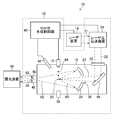
- FIG. 1 is a diagram schematically illustrating a configuration of an exemplary LPP type EUV light generation system.
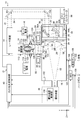
- FIG. 2 is a diagram schematically illustrating a configuration of an exemplary LPP type EUV light generation apparatus.
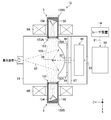
- FIG. 3 is a diagram schematically showing a configuration of an EUV light generation device including an ion catcher.
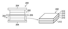
- FIG. 4 is a diagram schematically showing a configuration of a piezo actuator.
- FIG. 5 is a diagram illustrating a schematic configuration example of a vibration unit.
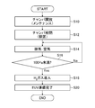
- FIG. 6 is a flowchart illustrating an example of processing contents of the operation preparation of the chamber.
- FIG. 7 is a flowchart showing an example of processing contents of the maintenance preparation of the chamber.
- FIG. 1 is a diagram schematically illustrating a configuration of an exemplary LPP type EUV light generation system.
- FIG. 2 is a diagram schematically illustrating a configuration of an exemplary LPP type EUV light generation apparatus.
- FIG. 3 is a diagram schematically showing a
- FIG. 8 is a graph showing the relationship between the internal pressure of the chamber and the breakdown voltage of the piezo element.
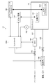
- FIG. 9 is a diagram schematically illustrating a configuration related to an interlock in the EUV light generation apparatus according to the first embodiment.
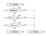
- FIG. 10 is a flowchart illustrating an example of processing contents when a voltage is not applied to the piezo actuator in the interlock according to the first embodiment.
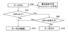
- FIG. 11 is a flowchart illustrating an example of processing contents when a voltage is applied to the piezo actuator in the interlock according to the first embodiment.
- FIG. 12 is a diagram schematically illustrating a configuration related to an interlock in the EUV light generation apparatus according to the second embodiment.
- FIG. 13 is a flowchart illustrating an example of processing contents when a voltage is not applied to the piezo actuator in the interlock according to the second embodiment.
- FIG. 14 is a flowchart illustrating an example of processing contents when a voltage is applied to the piezo actuator in the interlock according to the second embodiment.
- FIG. 15 is a diagram schematically showing a configuration of an exposure apparatus connected to the EUV light generation apparatus.
- Embodiment 1 7.1 Configuration 7.2 Operation 7.3 Function / Effect 8.
- Embodiment 2 8.1 Configuration 8.2 Operation 8.3 Function / Effect 9.
- Combinations of embodiments Example of Manufacturing Method of Electronic Device Using EUV Light Generation Apparatus will be described in detail with reference to the drawings.
- the embodiments described below show some examples of the present disclosure and do not limit the content of the present disclosure.
- all of the configurations and operations described in each embodiment are not necessarily essential as the configurations and operations of the present disclosure.
- the same components are denoted by the same reference numerals, and redundant description will be omitted.
- FIG. 1 schematically illustrates a configuration of an exemplary LPP type EUV light generation system 10.
- the EUV light generation device 12 is used together with at least one laser device 14.
- a system including the EUV light generation device 12 and the laser device 14 is referred to as an EUV light generation system 10.
- the EUV light generation device 12 includes a chamber 16 and a target supply unit 18.
- the chamber 16 is a sealable container.
- the target supply unit 18 is configured to supply a target material to the inside of the chamber 16, and is attached, for example, so as to penetrate a wall of the chamber 16.
- the material of the target substance may include, but is not limited to, tin, terbium, gadolinium, lithium, xenon, or a combination of any two or more thereof.
- At least one through hole is provided in the wall of the chamber 16.
- the through hole is closed by the window 20, and the pulse laser beam 22 output from the laser device 14 passes through the window 20.
- An EUV light focusing mirror 24 having, for example, a spheroidal reflecting surface is arranged inside the chamber 16.
- the EUV light focusing mirror 24 has a first focus and a second focus.
- the EUV light focusing mirror 24 is arranged, for example, such that its first focal point is located at the plasma generation region 26 and its second focal point is located at an intermediate focusing point (IF: Intermediate Focusing point) 28. .
- a through hole 30 is provided at the center of the EUV light focusing mirror 24, and the pulsed laser light 23 passes through the through hole 30.
- the EUV light generation device 12 includes an EUV light generation control unit 40, a target sensor 42, and the like.
- the target sensor 42 is configured to detect one or more of the presence, trajectory, position, and speed of the target 44.
- the target sensor 42 may have an imaging function.
- the EUV light generation device 12 includes a connection unit 48.
- the connection part 48 communicates the inside of the chamber 16 with the inside of the exposure apparatus 46.
- a wall 52 on which an aperture 50 is formed is provided inside the connection portion 48. The wall 52 is arranged such that its aperture 50 is located at the second focal position of the EUV light focusing mirror 24.
- the EUV light generation device 12 further includes a laser light transmission device 54, a laser light focusing mirror 56, a target collection unit 58, and the like.
- the laser light transmission device 54 includes an optical element and an actuator.
- the optical element defines the transmission state of the laser light.
- the actuator adjusts the position and orientation of the optical element.
- the target collecting unit 58 collects the target 44.
- the target collection unit 58 is disposed on an extension of the direction in which the target 44 output into the chamber 16 advances.
- the laser device 14 may be a MOPA (Master Oscillator Power Amplifier) system.
- the laser device 14 can be configured to include a master oscillator (not shown), an optical isolator (not shown), and a CO 2 laser amplifier (not shown).
- the laser device 14 may include a plurality of CO 2 laser amplifier.
- the wavelength of the laser light output from the master oscillator is, for example, 10.59 ⁇ m, and the repetition frequency of the pulse oscillation is, for example, 100 kHz.
- the operation of the exemplary LPP-type EUV light generation system 10 will be described with reference to FIG.
- the interior of chamber 16 is maintained at a pressure lower than atmospheric pressure, and may preferably be a vacuum.
- a gas having a high EUV light transmittance exists inside the chamber 16.
- the gas existing inside the chamber 16 may be, for example, hydrogen gas.
- the pulsed laser light 21 output from the laser device 14 passes through the window 20 as the pulsed laser light 22 via the laser light transmission device 54 and enters the inside of the chamber 16.
- the pulsed laser light 22 travels inside the chamber 16 along at least one laser light path, is reflected by a laser light focusing mirror 56, and is irradiated as at least one target 44 as pulsed laser light 23.
- the target supply unit 18 is configured to output a target 44 formed of a target material toward the plasma generation region 26 inside the chamber 16.
- the target supply unit 18 forms droplets by, for example, a continuous jet method.
- the nozzle is vibrated to periodically vibrate the flow of the target material ejected in a jet form from the nozzle hole to periodically separate the target material.
- the separated target material may form a free interface by its own surface tension to form a droplet.
- the target 44 is irradiated with at least one pulse included in the pulse laser beam 23.
- the target 44 irradiated with the pulsed laser light 23 is turned into plasma, and the emitted light 60 is emitted from the plasma.
- the EUV light 62 included in the emitted light 60 is selectively reflected by the EUV light focusing mirror 24.
- the EUV light 62 reflected by the EUV light focusing mirror 24 is focused at the intermediate focusing point 28 and output to the exposure device 46.
- one target 44 may be irradiated with a plurality of pulses included in the pulsed laser light 23.
- the EUV light generation controller 40 is configured to control the overall control of the EUV light generation system 10.
- the EUV light generation controller 40 processes the detection result of the target sensor 42.
- the EUV light generation controller 40 controls, for example, the timing at which the target 44 is output, the output direction of the target 44, and the like, based on the detection result of the target sensor 42.
- the EUV light generation control unit 40 controls, for example, the oscillation timing of the laser device 14, the traveling direction of the pulsed laser light 22, the focusing position of the pulsed laser light 23, and the like.
- the various controls described above are merely examples, and other controls may be added as needed.
- Target is an object to be irradiated with laser light introduced into the chamber.
- the target irradiated with the laser light is turned into plasma and emits EUV light.
- the target is a source of plasma.
- Droplet is a form of target supplied to the interior of the chamber.
- a droplet can mean a droplet-shaped target that has become substantially spherical due to the surface tension of a molten target material.
- the path along which the droplet travels inside the chamber is called a “droplet trajectory”.
- Pulse laser light can mean laser light including a plurality of pulses. “Laser light” can mean not only pulsed laser light but also general laser light. “Laser optical path” means the optical path of the laser light.
- Pulsma light is radiation emitted from a plasmatized target.
- the emitted light includes EUV light.
- EUV light is an abbreviation for “extreme ultraviolet light”.
- Extreme ultraviolet light generator is described as “EUV light generator”.
- piezo element is synonymous with piezoelectric element.
- a piezo element used as a vibrating element for generating a droplet by applying vibration to a liquid target material may be referred to as “vibrating piezo”.
- piezo actuator means an actuator to which a piezo element is applied as a drive source.
- “Servo-on” includes a voltage application state to the piezo actuator when a desired operation of the piezo actuator is realized.
- the voltage application state to the piezo actuator may be “servo-on”, and the voltage interruption state to the piezo actuator may be “servo-off”.
- the state where a voltage equal to or higher than the specified value is applied to the piezo actuator is set to “servo-on”, and the voltage lower than the specified value is set to the piezo actuator.
- the state applied to the actuator may be “servo-off”.
- Voltage application may include switching from non-voltage supply to voltage supply to the piezo actuator under control of the controller between the power supply device and the piezo actuator in a state where the power supply device is operated.
- No voltage application may include switching from voltage supply to the piezo actuator to non-voltage supply under control of the controller between the power supply device and the piezo actuator in a state where the power supply device is operated.
- Voltage application may include a voltage increase from a voltage less than a predetermined value to a voltage equal to or more than a specified value
- voltage not applied may include a voltage decrease from a voltage equal to or more than a specified value to a voltage less than a specified value.
- Voltage application and “voltage non-application” can also be applied to the vibration piezo.
- FIG. 2 is a diagram schematically showing a configuration of the EUV light generation device.
- XYZ orthogonal coordinate axes are introduced for convenience of description regarding directions.
- the direction in which EUV light is led from the chamber 16 toward the exposure device 46 is defined as the Z-axis direction.
- the X axis and the Y axis are axes orthogonal to the Z axis and orthogonal to each other.
- the central axis direction of the nozzle 126 that outputs the target material is defined as the direction of the Y axis.
- the direction of the Y axis is the trajectory direction of the droplet.
- the direction perpendicular to the paper surface of FIG. 2 is defined as the direction of the X axis.
- 3 and subsequent drawings are the same as the coordinate axes introduced in FIG.
- the EUV light generation device 12 includes the chamber 16, the laser light transmission device 54, and the EUV light generation control unit 40.
- the EUV light generation device 12 may include a laser device 14.
- the chamber 16 includes the target supply unit 18, the stage 66, the timing sensor 80, the window 20, the laser light focusing optical system 90, the EUV light focusing mirror 24, the target recovery unit 58, and the pressure sensor 102.
- the target supply unit 18 includes a droplet generator 110, a pressure regulator 112, a piezo power supply 114, and a heater power supply 116.
- Each of the pressure regulator 112, the piezo power supply 114, and the heater power supply 116 is connected to the EUV light generation controller 40.
- the droplet generator 110 includes a tank 120, a nozzle 126, a vibrating piezo 128, and a heater 130.
- the tank 120 stores the target material.
- the nozzle 126 includes a nozzle hole 124.
- the nozzle holes 124 output droplets 122 of the target material.
- the excitation piezo 128 is arranged near the nozzle 126.
- the vibration piezo 128 is an example of the “piezo element provided inside the chamber” in the present disclosure.
- the heater 130 is disposed on the outer side surface of the tank 120.
- the target material is, for example, tin (Sn).
- At least the inside of the tank 120 is made of a material that does not easily react with the target substance.
- Examples of a material that does not easily react with tin which is an example of the target material include, for example, silicon carbide (SiC), silicon dioxide (SiO 2 ), aluminum oxide (Al 2 O 3 ), molybdenum (Mo), tungsten (W), and tantalum. Any of (Ta) can be used.
- the pressure regulator 112 is connected to the tank 120 via the pipe line 113.
- the pressure regulator 112 is disposed in a pipe between an inert gas introduction unit (not shown) and the tank 120.
- the inert gas inlet may include a gas cylinder filled with an inert gas such as helium, argon, or the like.
- the inert gas introduction unit may introduce an inert gas into the tank 120 via the pressure regulator 112.
- the pressure regulator 112 can be connected to an exhaust pump (not shown).
- the pressure regulator 112 includes a solenoid valve (not shown) for introduction and exhaust, a pressure sensor (not shown), and the like inside.
- the pressure regulator 112 can detect the internal pressure of the tank 120 using a pressure sensor (not shown).
- the pressure regulator 112 can operate an exhaust pump (not shown) to exhaust gas inside the tank 120.
- the pressure regulator 112 outputs a detection signal of the detected pressure to the EUV light generation controller 40.
- the EUV light generation controller 40 outputs a control signal for controlling the operation of the pressure regulator 112 based on the detection signal output from the pressure regulator 112 so that the inside of the tank 120 has a target pressure. It is supplied to the controller 112.
- the piezo power supply 114 is connected to the excitation piezo 128.
- the heater power supply 116 is connected to the heater 130.
- the stage 66 moves the droplet generator 110 to at least a designated position on the XZ plane based on a command from the EUV light generation controller 40.
- the chamber 16 includes a first container 16A and a second container 16B.
- the second container 16B is a container that communicates with the first container 16A, and is connected to the first container 16A via the stage 66 and the support plate 67.
- the second container 16B is fixed to the stage 66.
- the droplet generator 110 is fixed to the second container 16B. That is, the droplet generator 110 is fixed to the stage 66 via the second container 16B.
- the support plate 67 is fixed to the first container 16A.
- the stage 66 is configured to move on the support plate 67 at least in the XZ plane.
- the first container 16A fixed to the support plate 67 is a fixed container fixedly arranged at a predetermined position.
- the second container 16B fixed to the stage 66 is a movable container that can move on the support plate 67.
- the timing sensor 80 includes a light source unit 81 and a light receiving unit 82.
- the light source unit 81 and the light receiving unit 82 are arranged so as to face each other with a droplet trajectory 140 that is a traveling path of the droplet 122 interposed therebetween.
- the light source unit 81 includes a light source 83 and an illumination optical system 84.
- the light source unit 81 is arranged so as to illuminate a droplet in the detection region 142 on the droplet trajectory 140 between the nozzle hole 124 of the droplet generator 110 and the plasma generation region 26.
- the light source 83 may be a monochromatic laser light source or a lamp that emits a plurality of wavelengths. Further, the light source 83 may include an optical fiber, and the optical fiber is connected to the illumination optical system 84.
- the illumination optical system 84 includes a condenser lens.
- the illumination optical system 84 includes a window 85. Window 85 is located on the wall of chamber 16.
- the light receiving section 82 includes a light receiving optical system 86 and an optical sensor 87.
- the light receiving unit 82 is arranged to receive the illumination light that is at least a part of the illumination light output from the light source unit 81 and has passed through the detection region 142.
- the light receiving optical system 86 includes a condenser lens.
- the light receiving optical system 86 includes a window 88. Window 88 is located on the wall of chamber 16.
- the optical sensor 87 includes one or a plurality of light receiving surfaces.
- the optical sensor 87 can be configured by any one of a photodiode, a photodiode array, an avalanche photodiode, a photomultiplier, a multi-pixel photon counter, and an image intensifier.
- the optical sensor 87 outputs an electric signal according to the amount of received light.
- the window 85 of the light source unit 81 and the window 88 of the light receiving unit 82 are arranged at positions facing each other with the droplet trajectory 140 interposed therebetween.
- the facing direction of the light source unit 81 and the light receiving unit 82 may be orthogonal to the droplet trajectory 140, or may be non-orthogonal to the droplet trajectory 140.
- the timing sensor 80 is an example of the target sensor 42 shown in FIG.
- the laser light transmission device 54 includes a first high-reflection mirror 151 and a second high-reflection mirror 152 as optical elements for defining the traveling direction of the laser light.
- the laser light focusing optical system 90 is arranged so that the pulsed laser light 22 output from the laser light transmission device 54 is input.
- the laser beam focusing optical system 90 is configured to focus the pulsed laser beam 23 incident on the chamber 16 through the window 20 to the plasma generation region 26.
- the laser light focusing optical system 90 includes a laser light focusing mirror 56, a high reflection flat mirror 93, and a laser light manipulator 94.
- the laser light focusing optical system 90 is an example of the “laser focusing optical unit” in the present disclosure.
- the laser light focusing mirror 56 is, for example, a high reflection off-axis parabolic mirror.
- the laser light focusing mirror 56 is held by a mirror holder 56A.
- the mirror holder 56A is fixed to the plate 95.
- the high reflection flat mirror 93 is held by a mirror holder 93A.
- the mirror holder 93A is fixed to the plate 95.
- the laser light manipulator 94 is configured using, for example, a stage that can move the plate 95 in directions of three axes orthogonal to each other, that is, the X axis, the Y axis, and the Z axis.
- the laser light manipulator 94 is configured to be able to move the laser irradiation position in the chamber 16 to a position designated by the EUV light generation controller 40 in the directions of the X axis, the Y axis, and the Z axis.
- the laser light manipulator 94 includes a piezo actuator 94A as a driving source of the stage.
- the piezo actuator 94A is connected to a piezo actuator controller 98.
- the EUV light focusing mirror 24 is held by an EUV light focusing mirror holder 96.
- the EUV light focusing mirror holder 96 is fixed to the plate 97.
- the plate 97 is a member that holds the laser light focusing optical system 90 and the EUV light focusing mirror 24.
- the plate 97 is fixed to the inner wall of the chamber 16.
- the chamber 16 is connected to the exhaust passage 103 via an exhaust port (not shown).
- the exhaust passage 103 is provided with an exhaust valve 104 and a vacuum pump 106.
- the chamber 16 is connected to a gas introduction channel 107 via a gas introduction port (not shown).
- the gas introduction flow path 107 is provided with a mass flow controller (MFC) 108 and an introduction valve 109.
- the gas introduction flow path 107 is connected to a gas introduction source (not shown).
- the purge gas shown in FIG. 2 represents a general term for a gas introduced into the chamber 16 at the time of purging. Examples of the purge gas include an argon gas (Ar gas) and a nitrogen gas (N 2 gas).
- the EUV light generation controller 40 is connected to each of the stage 66, the timing sensor 80, and the piezo actuator controller 98. Further, the EUV light generation controller 40 is connected to the pressure sensor 102, the exhaust valve 104, the vacuum pump 106, the mass flow controller 108, the introduction valve 109, and the exposure device controller 156.
- the exposure device control section 156 is a control device that controls the exposure device 46. The exposure device control section 156 may be included in the exposure device 46.
- the control device such as the EUV light generation controller 40 and the processing unit can be realized by a combination of hardware and software of one or more computers.
- the computer may be configured to include a CPU (Central Processing Unit) and a memory.
- Software is synonymous with program.
- a programmable controller is included in the concept of a computer.
- a part or all of the processing functions of the control device such as the EUV light generation controller 40 may be realized by using an integrated circuit represented by an FPGA (Field Programmable Gate Array).
- An ASIC Application Specialized Integrated Circuit
- FPGA Field Programmable Gate Array
- control devices may be connected to each other via a communication network such as a local area network or the Internet.
- program units may be stored in both local and remote memory storage devices.
- the EUV light generation controller 40 controls the exhaust valve 104 and the vacuum pump 106 so that the inside of the chamber 16 is in a vacuum state.
- the EUV light generation controller 40 controls the exhaust from the chamber 16 based on the detection value of the pressure sensor 102 so that the inside of the chamber 16 is within a predetermined pressure range.
- the EUV light generation controller 40 controls gas introduction into the chamber 16 based on the detection value of the pressure sensor 102 so that the inside of the chamber 16 is within a predetermined pressure range.
- the UVEUV light generation controller 40 controls the opening and closing of the exhaust valve 104 and the number of revolutions of the vacuum pump 106, and exhausts gas until the inside of the chamber 16 becomes lower than a predetermined pressure.
- the EUV light generation controller 40 controls the operation of the mass flow controller 108 and the opening and closing of the vacuum pump 106, and introduces gas until the inside of the chamber 16 has a predetermined pressure or more.
- the predetermined pressure may be, for example, 1 Pascal [Pa].
- the exhaust valve 104 and the vacuum pump 106 are examples of components of the “exhaust unit that exhausts gas inside the chamber 16 to the outside of the chamber 16” in the present disclosure.
- the mass flow controller 108 and the introduction valve 109 are examples of components of the “gas introduction unit that introduces gas into the chamber” in the present disclosure.
- the gas introduction may include a gas introduction source.
- the EUV light generation control unit 40 drives the heater 130 via the heater power supply 116 to heat the target material inside the tank 120 to a predetermined temperature equal to or higher than the melting point while monitoring the temperature with a temperature sensor (not shown). Control to maintain.
- the predetermined temperature may be, for example, a temperature in the range of 250 ° C. to 290 ° C.
- the target material stored in the tank 120 is melted by heating using the heater 130 to become a liquid.
- the molten tin is an example of the “liquid target material” in the present disclosure.
- the UVEUV light generation controller 40 controls the pressure regulator 112 so that the inside of the tank 120 has a predetermined pressure in order to discharge the liquid target material from the nozzle hole 124.
- the predetermined pressure inside the tank 120 may be, for example, 3 megapascal [MPa] or more.
- the pressure regulator 112 introduces gas into the tank 120 based on a control signal from the EUV light generation controller 40, or exhausts the gas inside the tank 120 and pressurizes or depressurizes the inside of the tank 120. I can do it.
- the pressure inside the tank 120 is adjusted by the pressure adjuster 112 to a target pressure value.
- the gas introduced into the tank 120 is preferably an inert gas.
- the pressure regulator 112 adjusts the internal pressure of the tank 120 to a predetermined value so that the droplet 122 reaches the plasma generation region 26 at a predetermined speed according to an instruction from the EUV light generation controller 40.
- the predetermined speed of the droplet may be, for example, a speed in a range from 60 m / s to 120 m / s.
- the predetermined value of the internal pressure of the tank 120 may be, for example, a pressure in a range from several MPa to 40 MPa.
- the EUV light generation control unit 40 supplies a voltage having a predetermined waveform from the piezo power supply 114 to the excitation piezo 128, and the liquid target material output from the nozzle hole 124 regularly drops the droplet 122 at a predetermined piezo driving frequency. Is adjusted so as to generate. By performing the duty adjustment, an appropriate duty value suitable for generating the droplet 122 is set.
- the EUV light generation controller 40 supplies a predetermined piezo drive frequency and a predetermined duty voltage to the vibrating piezo 128 via the piezo power supply 114 so that the liquid target substance output from the nozzle hole 124 generates the droplet 122. I do. That is, the EUV light generation controller 40 transmits a piezo drive voltage waveform signal to the piezo power supply 114.
- the piezo power supply 114 supplies a voltage to the vibrating piezo 128 in accordance with an instruction from the EUV light generation controller 40.
- a voltage is applied to the excitation piezo 128, the excitation piezo 128 vibrates.
- the vibration of the excitation piezo 128 is transmitted to the nozzle 126, and the liquid target material vibrates through the nozzle hole 124.
- the jet of the liquid target material output from the nozzle hole 124 advances while breaking up into droplets.
- the droplets coalesce and the droplets 122 having substantially the same volume are periodically generated. Then, the droplet 122 can be supplied to the plasma generation region 26.
- the pulsed laser light output from the laser device 14 is guided to the plasma generation region 26 via the first high-reflection mirror 151, the second high-reflection mirror 152, and the laser light focusing optical system 90, and is transmitted to the droplet 122. Irradiated.
- the illumination light to the droplet 122 output from the light source unit 81 is received by the light receiving unit 82.
- the intensity of light received by the light receiving unit 82 may decrease in synchronization with the passage of the droplet 122 through the detection region 142.
- the change in light intensity is detected by the optical sensor 87.
- the optical sensor 87 outputs the detection result to the EUV light generation controller 40 as a passage timing signal.
- the EUV light generation controller 40 When the pulse laser beam 23 is applied to the droplet 122, the EUV light generation controller 40 generates a droplet detection signal indicating the passage timing of the droplet at a timing when the passage timing signal exceeds a predetermined threshold voltage.
- the detection region 142 may be a region where a droplet detection signal is generated when the droplet 122 passes between the light source unit 81 and the light receiving unit 82.
- the EUV light generation control unit 40 generates a light emission trigger signal by adding a predetermined delay time to the droplet detection signal. That is, the EUV light generation controller 40 can generate a light emission trigger signal by adding a delay time to the droplet detection signal by a delay circuit (not shown). The EUV light generation controller 40 inputs a light emission trigger signal to the laser device 14.
- the delay time of the delay circuit is set so that the emission trigger signal is input to the laser device 14 before the droplet 122 passes through the detection region 142 and reaches the plasma generation region 26.
- the delay time is set such that the pulse laser light output from the laser device 14 is irradiated on the droplet 122 when the droplet reaches the plasma generation region 26.
- the laser device 14 When the light emission trigger signal is input to the laser device 14, the laser device 14 outputs a pulse laser beam 21.
- the pulsed laser light 21 output from the laser device 14 is input to the laser light focusing optical system 90 via the laser light transmission device 54 and the window 20.
- the EUV light generation controller 40 may control the stage 66 to move the droplet generator 110 so that the droplet 122 passes through the plasma generation region 26.
- the EUV light generation controller 40 controls the piezo actuator 94A so that the pulsed laser light 23 is focused on the plasma generation region 26.
- the pulse laser beam 23 is focused and irradiated on the droplet 122 in the plasma generation region 26 by the laser beam focusing optical system 90.
- the target is turned into plasma and the EUV light 62 is generated by condensing and irradiating the droplet 122 with the pulse laser light 23.
- the EUV light 62 may be periodically generated by condensing and irradiating the pulse laser light 23 to the droplet 122 supplied from the target supply unit 18 to the plasma generation region 26 at a predetermined cycle.
- the EUV light 62 generated from the plasma generation region 26 is collected by the EUV light collecting mirror 24, condensed at the intermediate converging point 28, and then input to the exposure device 46.
- the droplet 122 that has not been irradiated with the pulse laser beam 23 passes through the plasma generation region 26 and enters the target collection unit 58.
- the droplets 122 collected in the target collection unit 58 can be stored as a liquid target material.
- the plasma generation region 26 may be moved by a command from the exposure device 46.
- the output position of the droplet 122 is changed by the stage 66, and the irradiation position of the pulse laser light 23 is changed by the piezo actuator 94A.
- the EUV light generation apparatus 12 illustrated in FIG. 2 is an example of an apparatus that can execute the “extreme ultraviolet light generation method” in the present disclosure.
- FIG. 3 is a diagram schematically illustrating a configuration of an EUV light generation device including the ion catcher.
- the EUV light generation device 12 includes the ion catcher 5.
- the ion catcher 5 includes a tubular member 150, a first collision unit 153, and a second collision unit 154.
- the first end 150A of the tubular member 150 is an end closer to the plasma generation region 26.
- the first end 150A is open in a direction along the magnetic field 155.
- the first end portion 150A is provided with a first collision portion 153.
- the second end 150B of the tubular member 150 is an end farther from the plasma generation region 26.
- the second end 150B is provided with a second collision portion 154.
- the first collision section 153 includes a plurality of plate members 153A.
- the plurality of plate members 153A are arranged diagonally at intervals.
- Each of the plurality of plate members 153A has a collision surface against which ions or neutral particles collide.
- the second collision portion 154 has a conical or polygonal pyramid surface.
- the cylindrical member 150 is arranged at a position penetrating the bores of the coils constituting the magnets 6A and 6B. Therefore, a strong magnetic field 155 is formed inside the cylindrical member 150.
- an electromagnet including a coil can be applied as each of the magnets 6A and 6B.
- the magnet 6A and the magnet 6B are arranged at positions facing each other across the chamber 16 so that the center axes of the coils coincide.
- the magnet 6A and the magnet 6B are configured so as to form a magnetic field inside the chamber 16.
- the magnetic field formed by the magnets 6A and 6B may be strongest near the center of the bore of each coil and slightly weaker between the magnets 6A and 6B.
- the first collision unit 153 captures the ions or neutral particles.
- ions or neutral particles may enter inside the tubular member 150 without being collected.
- the ions are decelerated.
- Neutral particles are also decelerated when reflected by the first collision unit 153. Therefore, the ions or neutral particles are not reflected by the second collision portion 154, and easily adhere to the second collision portion 154.
- the inside of the cylindrical member 150 becomes a relaxation space for decelerating ions or neutral particles, and can efficiently collect ions or neutral particles.
- ⁇ ⁇ ⁇ Ions contained in the plasma may experience Lorentz force perpendicular to both the direction of the magnetic field and the moving direction of the ions when trying to diffuse from the plasma generation region 26. Due to the Lorentz force, the movement trajectory of the ions when viewed from a direction parallel to the magnetic field may have a substantially circular shape. That is, the ions may move spirally along the magnetic field.
- FIG. 4 is a diagram schematically showing a configuration of a piezo actuator.
- the piezo actuator 200 shown in FIG. 4 can be applied to the piezo actuator 94A shown in FIG.
- the piezo actuator 200 includes a piezo element 202, a stator 204, and a mover 206.
- each of the plurality of piezo elements 202 is supported by the stator 204. Further, a plurality of piezo elements 202 are connected to one mover 206.
- a piezo element that operates so as to expand and contract in the direction of an electric field can be applied.
- a piezo element that operates so as to generate a shear strain perpendicular to an electric field can be applied.
- the piezoelectric element 202 has a structure in which a piezoelectric body 210 is sandwiched between two electrodes 212.
- FIG. 4 illustrates a laminated piezo element as the piezo element 202, but a single-layer piezo element may be applied to the piezo element 202.
- Piezo element 202 shown in FIG. 4 undergoes bending deformation when a voltage is applied to electrode 212.
- the mover 206 connected to the piezo element 202 moves according to the voltage application.
- the piezoelectric actuator 200 can apply pressure to the mover by applying a predetermined voltage, and can maintain the position of the mover 206.
- the piezo actuator 200 can move the mover 206 according to a change in the voltage applied to the piezo element 202.
- the piezo element 202 applied to the piezo actuator 200 is an example of the “piezo element provided inside the chamber” in the present disclosure.
- FIG. 5 is a diagram illustrating a schematic configuration example of an exciting unit.
- FIG. 5 is a cross-sectional view of a plane including the central axis of the two first bolts 308 of the vibration unit 310, and shows a schematic configuration when the nozzle hole 124 and the vibration unit 310 are viewed from the output direction of the target.
- FIG. 5 is a diagram illustrating a schematic configuration example of an exciting unit.
- FIG. 5 is a cross-sectional view of a plane including the central axis of the two first bolts 308 of the vibration unit 310, and shows a schematic configuration when the nozzle hole 124 and the vibration unit 310 are viewed from the output direction of the target.
- FIG. 5 is a diagram illustrating a schematic configuration example of an exciting unit.
- FIG. 5 is a cross-sectional view of a plane including the central axis of the two first bolts 308 of the vibration unit 310, and shows a schematic configuration when the nozzle hole 124 and the vibration unit 310
- the vibration unit 310 shown in FIG. 5 is an example of a structure for attaching the vibration piezo 128 shown in FIG.
- the nozzle holder 127 shown in FIG. 5 is a member for attaching the nozzle 126 shown in FIG.
- the vibration unit 310 includes two first bolts 308, a second bolt 306, a pressurizing frame 307, a pressing member 315, a piezo element 314, and a vibration transmitting member 311.
- the vibration unit 310 further includes an electrode 312 and an insulating member 313.
- the pressurizing frame 307 is a frame member of the vibration unit 310.
- the pressurizing frame 307 includes arm portions 307b located on both sides, the other arm portion 307b, and a central beam portion 307a connecting them.
- the vibration transmitting member 311 is disposed between the pressurizing frame 307 and the nozzle holder 127. At the center of the vibration transmitting member 311, a truncated cone-shaped protrusion 302 having a thin tip is provided. The tip of the protrusion 302 contacts the side surface of the nozzle holder 127.
- Two first bolts 308 fix the pressurizing frame 307 and the vibration transmitting member 311 to the side surface of the nozzle holder 127.
- the second bolt 306 presses the piezo element 314 and the vibration transmitting member 311 to the nozzle holder 127 via the pressing member 315.
- the electrode 312 and the insulating member 313 are arranged between the second bolt 306 and the piezo element 314. At this time, the electrode 312 and the piezo element 314 are in contact.
- the electrode 312 and the second bolt 306 are electrically insulated by the insulating member 313.
- the vibration transmitting member 311 can function as an electrode of the piezo element 314 that forms a pair with the electrode 312.
- any member that is electrically connected to the vibration transmission member 311 may be grounded.
- FIG. 5 shows a case where the vibration transmission member 311 is grounded.
- the electrode 312 is connected to a piezo power supply 114 shown in FIG. 2 via a connection line (not shown).
- the frequency of the voltage supplied from the piezo power supply 114 to the electrode 312 may be lower than the resonance frequency of the piezo element 314.
- the piezo element 314 may be a composite piezo element.
- the composite piezo element is a piezo element formed by solidifying integrated minute bulk piezos with a resin.
- the resonance frequency of the piezo element 314 may be, for example, 4 MHz or more.
- a bulk piezo element may be used as the piezo element 314.
- the above preload can be adjusted by adjusting the screwing torque of the first bolt 308 and the second bolt 306. At this time, the screwing torque of the first bolt 308 and the second bolt 306 is adjusted so that the vibration generated by the piezo element 314 reaches the target material inside the tank 120 via the protrusion 302 of the vibration transmitting member 311. It may be adjusted.
- the piezo element 314 can generate vibration by expanding and contracting based on a voltage having a predetermined waveform applied from the piezo power supply 114.
- the generated vibration may be transmitted to the target material inside the target channel via the protrusion 302 of the vibration transmission member 311, the nozzle holder 127, the nozzle 126, the tank 120, and the like. Accordingly, the jet of the target material discharged from the nozzle hole 124 can be changed to a droplet having a predetermined size and a predetermined period.
- the vibration transmitting member 311 is cooled by the cooling water flowing through the cooling water pipe 303. This can prevent the temperature of the piezo element 314 from becoming equal to or higher than the Curie point due to heat from the heater 130 transmitted through the tank 120, the nozzle holder 127, and the like.
- the Curie point of the piezo element 314 may be in a range of 150 ° C. to 350 ° C.
- a voltage is applied to the piezo element 314 from the piezo power supply 114.
- the frequency of the voltage may be lower than the resonance frequency of the piezo element 314, for example, less than 4 MHz.
- the frequency of the voltage may be, for example, 3 MHz.
- the piezo element 314 can vibrate at a frequency equal to or lower than the resonance frequency. Thereby, generation of vibration noise can be suppressed.
- Composite piezo elements having a resonance frequency of 3 MHz to 6 MHz may be relatively easily available. Therefore, the frequency of the voltage applied to the piezo element 314 may be set in a range from 2 MHz to 5 MHz.
- ⁇ Vibration can also be amplified by the resonance of a component when its frequency generally matches the natural frequency of the component on the vibration transmission path. Therefore, in order to suppress the amplification of the vibration noise by the components on the vibration transmission path including the vibration transmission member 311, it is preferable that the frequency of the vibration noise that can be generated does not match the natural frequency of the component.
- the piezo element 314 illustrated in FIG. 5 is an example of the “piezo element provided inside the chamber” in the present disclosure.
- FIG. 6 is a flowchart showing an example of processing contents for preparation for operation of the chamber. 6 includes a chamber opening step S10, a chamber closing step S12, an exhaust step S14, an exhaust pressure determination step S16, a gas introduction step S18, and an operation preparation completion processing step S20.
- the chamber opening step S10 for example, the chamber 16 disposed in the EUV light generation device 12 shown in FIG.
- the chamber opening step S10 after the chamber 16 is opened to the atmosphere, maintenance or the like inside the chamber 16 can be performed.
- the chamber sealing step S12 for example, the inside of the chamber 16 after the maintenance is performed is sealed.
- the maintenance includes, for example, replacement of an optical member such as the EUV light focusing mirror 24 shown in FIG. 2, replacement of the droplet generator 110, adjustment of the optical axis of the pulse laser light 23 irradiating the droplet 122, and the like.
- the EUV light generation controller 40 shown in FIG. 2 opens the evacuation valve 104, operates the vacuum pump 106, and performs evacuation of the inside of the chamber 16. Thereby, gas such as air inside the chamber 16 can be discharged to the outside of the chamber 16.
- the EUV light generation controller 40 determines whether the internal pressure of the chamber 16 is less than 100 Pa based on the value detected by the pressure sensor 102. If the detection value of the pressure sensor 102 is 100 Pa or more, the determination is No, and the EUV light generation controller 40 continues the exhaust process S14.
- the EUV light generation controller 40 closes the exhaust valve 104, stops the operation of the vacuum pump 106, and ends the exhaust of the chamber 16. I do. Thereafter, the process proceeds to the gas introduction step S18.
- the EUV light generation controller 40 introduces hydrogen gas into the interior of the chamber 16 from a hydrogen gas introduction port (not shown) via a hydrogen gas (H 2 gas) introduction flow path (not shown).
- a hydrogen gas (H 2 gas) introduction flow path not shown.
- the same configuration as the purge gas introduction channel can be applied to the hydrogen gas introduction channel.
- the internal pressure of the chamber 16 can be specified to be less than 100 Pa.
- the internal pressure of the chamber 16 may be set to 70 Pa.
- the operation preparation completion processing step S20 after the inside of the chamber 16 reaches a predetermined pressure, the operation proceeds to the operation preparation completion processing step S20.
- the EUV light generation controller 40 performs operation preparation of the chamber 16 necessary for emission of EUV light. After the operation preparation completion processing step S20, the EUV light generation device 12 can emit EUV light.
- FIG. 7 is a flowchart showing an example of processing contents of chamber maintenance preparation.
- the flowchart of the maintenance preparation of the chamber shown in FIG. 7 includes a gas introduction stopping step S30, a gas exhausting step S32, a purge gas introducing step S34, a purge gas exhausting step S36, a purge gas reintroducing step S38, and a chamber opening step S40.
- the EUV light generation controller 40 stops the introduction of hydrogen gas into the chamber 16.
- the EUV light generation controller 40 opens the exhaust valve 104, operates the vacuum pump 106, and exhausts the hydrogen gas inside the chamber 16. After the pressure inside the chamber 16 becomes equal to or lower than the predetermined pressure, the EUV light generation controller 40 closes the exhaust valve 104 and stops the operation of the vacuum pump 106. Thereafter, the process proceeds to the purge gas introduction step S34.
- the EUV light generation controller 40 opens the introduction valve 109, operates the mass flow controller 108, and introduces a purge gas from the gas introduction source into the chamber 16.
- a purge gas argon gas or nitrogen gas may be applied.
- the pressure inside the chamber 16 becomes equal to or higher than the predetermined pressure, the process proceeds to a purge gas exhausting step S36.
- the EUV light generation controller 40 discharges the purge gas inside the chamber 16 to the outside of the chamber 16. That is, the EUV light generation controller 40 closes the introduction valve 109 and stops the operation of the mass flow controller 108. Further, the EUV light generation controller 40 opens the exhaust valve 104 and operates the vacuum pump 106. When the pressure inside the chamber 16 becomes equal to or lower than the predetermined pressure, the process proceeds to the purge gas re-introduction step S38.
- the purge gas introduction step S34 and the purge gas exhaust step S36 are components of the gas replacement step.
- the EUV light generation controller 40 may execute the purge gas re-introduction step S38 after performing the gas replacement step a plurality of times.
- the EUV light generation controller 40 introduces a purge gas into the chamber 16 until the inside of the chamber 16 reaches the atmospheric pressure. That is, the EUV light generation controller 40 closes the exhaust valve 104 and stops the operation of the vacuum pump 106. Further, the EUV light generation controller 40 opens the introduction valve 109 and operates the mass flow controller 108. After the purge gas re-introduction step S38, the process proceeds to the chamber opening step S40.
- the chamber 16 is opened to the atmosphere. Thereby, maintenance of the chamber 16 becomes possible.
- a piezo actuator for adjusting the positions of the laser light focusing mirror 56 and the high-reflection flat mirror 93 in order to adjust the irradiation position of the pulse laser light 23 irradiating the droplet 122 inside the chamber 16 shown in FIG. 94A is provided. Further, a vibration piezo 128 for discharging droplets is provided inside the chamber 16.
- the piezo element 202 shown in FIG. 4 can be applied to the piezo actuator 94A.
- the piezoelectric element 314 shown in FIG. 5 can be applied to the excitation piezo 128.
- the rotary motor when a rotary motor is used to move the stage to which the piezo actuator 94A is applied, the rotary motor may be affected by the magnetic field 155 shown in FIG. Also, the magnetic field generated by the rotary motor can affect the magnetic field 155 shown in FIG. Therefore, a piezo element that is hardly affected by the magnetic field 155 and does not generate a magnetic field that affects the magnetic field 155 is applied to the piezo actuator 94A.
- the piezo actuator 94A is driven when the internal pressure of the chamber 16 is within a specific range, such as a vacuum, for example, the piezo element, which is the driving source of the piezo actuator 94A, is broken by dielectric breakdown.
- the analysis of breakdown voltage in vacuum can refer to Paschen's law.
- Paschen's law spark discharge in a vacuum occurs when electrons accelerated by an electric field collide with gas molecules and ionize the gas. Therefore, the collision becomes less likely to occur when the amount of gas decreases, and the voltage required for spark discharge increases. Further, when the amount of gas increases, it becomes difficult for electrons to be sufficiently accelerated before collision, so that the voltage required for spark discharge increases. The voltage required for spark discharge has the lowest value in between.
- the Paschen curve representing the voltage required for spark discharge with respect to the value obtained by multiplying the gas pressure by the distance between the electrodes has the above tendency regardless of the type of gas.
- the voltage required for spark discharge differs for each value obtained by multiplying the gas pressure by the distance between the electrodes, depending on the type of gas.
- FIG. 8 is a graph showing the relationship between the internal pressure of the chamber and the breakdown voltage of the piezo element.
- a curve 350 shown in FIG. 8 shows an example in which an argon gas is introduced into the chamber 16.
- the inventors have derived a relationship between the internal pressure of the chamber 16 and the breakdown voltage of the piezo element shown in FIG.
- VV1 shown in FIG. 8 is the operating voltage of the piezo element applied to the piezo actuator 94A shown in FIG. V2 is the operating voltage of the vibrating piezo 128.
- the “operating voltage” indicates a voltage applied to the piezo element when the piezo element performs a predetermined operation.
- P1 represents the lower pressure limit of the voltage application prohibition pressure range applied to the piezo actuator 94A.
- the voltage application prohibition pressure range is a pressure range in which dielectric breakdown occurs when a voltage is applied.
- P2 represents the upper pressure limit of the voltage application prohibition pressure range applied to the piezo actuator 94A.
- P11 represents the lower pressure limit of the voltage application prohibition pressure range applied to the vibration piezo 128.
- P12 represents the upper pressure limit of the voltage application prohibition pressure range applied to the vibration piezo 128.
- the lower pressure limit P1 of the voltage application prohibition pressure range in the argon gas atmosphere is 100 Pa
- the upper pressure limit P2 of the voltage application prohibition pressure range is 400 kPa [kPa]. is there.
- the breakdown voltage is 150 V
- the lower pressure limit P11 of the voltage application prohibition pressure range in the argon gas atmosphere is 150 Pa
- the upper pressure limit P22 of the voltage application prohibition pressure range is 300 kPa.
- the voltage application prohibition pressure range can be set to 100 Pa or more and 400 kPa or less. Further, when the applied voltage of the piezo element is 150 V, the voltage application prohibition pressure range may be 150 Pa or more and 300 kPa or less.
- Table 1 shows the relationship between the type of gas introduced into the chamber 16 and the voltage application prohibition pressure range.
- Table 1 shows the pressure lower limit value P1 and the pressure upper limit value P2 of the voltage application prohibition pressure range when the applied voltage of the piezo element is 250V.
- the pressure lower limit value P1 of the voltage application prohibition pressure range is 100 Pa.
- the pressure upper limit value P2 of the voltage application prohibition pressure range is 50 kPa.
- the pressure upper limit value P2 of the voltage application prohibition pressure range is 10 kPa.
- the voltage application prohibition pressure range of the piezo actuator shown in FIG. 8 is an example of the “first range” in the present disclosure.
- the pressure application prohibition pressure range of the excitation piezo is an example of the “first range” in the present disclosure.
- the voltage application prohibition pressure range that is equal to or more than the lower pressure limit and equal to or less than the upper pressure limit for each type of gas shown in Table 1 is an example of the “first range” in the present disclosure.
- the internal pressure of the chamber 16 varies from atmospheric pressure to vacuum.
- the internal pressure of the chamber 16 passes through the piezo actuator voltage application prohibition pressure range and the excitation piezo voltage application prohibition pressure range shown in FIG.
- an impurity such as an argon gas or a nitrogen gas is removed.
- An active gas is introduced into the chamber 16.
- an argon gas or a nitrogen gas is exhausted to the outside of the chamber 16.
- an argon gas or a nitrogen gas is introduced into the chamber 16 until the inside of the chamber 16 becomes the atmospheric pressure.
- the chamber opening step S40 air is released when the chamber 16 is opened. Inflow.
- the internal pressure of the chamber 16 varies from vacuum to atmospheric pressure.
- the internal pressure of the chamber 16 passes through the piezo actuator voltage application prohibition pressure range and the excitation piezo voltage application prohibition pressure range shown in FIG.
- the internal pressure of the chamber 16 passes through the voltage application prohibition pressure range of the piezo actuator and the voltage application prohibition pressure range of the vibrating piezo.
- An interlock is required to prohibit the application of voltage to the power supply. The same applies to the process in which the internal pressure of the chamber 16 changes from vacuum to atmospheric pressure.
- the internal pressure of the chamber 16 may fall within the voltage application prohibition pressure range of the piezo actuator and the voltage application prohibition pressure range of the vibrating piezo. It is necessary to interlock properly.
- Embodiment 1 7.1 Configuration First, the interlock during normal operation of the EUV light generation device 12 will be described. Note that “during normal operation” indicates a period during which normal operation is performed.
- the normal operation includes a period during which EUV light is emitted.
- the normal operation may include, for example, a period during which the chamber is ready for operation before the emission of the EUV light illustrated in FIG. 6.
- the exhaust step S14 of the processing for preparing the operation of the chamber shown in FIG. 6 is a step that particularly requires an interlock.
- FIG. 9 is a diagram schematically illustrating a configuration related to an interlock in the EUV light generation apparatus according to the first embodiment.
- FIG. 9 shows some components of the EUV light generation device 12 shown in FIG.
- the controller 40A controls the piezo actuator 94A via the piezo actuator controller 98 based on the detection value of the pressure sensor 102. Further, the controller 40 ⁇ / b> A controls the vibration piezo 128 via the piezo power supply 114 based on the detection value of the pressure sensor 102.
- the EUV light generation device 12 includes a storage unit (not shown).
- the storage unit (not shown) stores the relationship between the applied voltage of the piezo element and the voltage application prohibition pressure range for each gas introduced into the chamber 16.
- the controller 40A can read information on the voltage application prohibition pressure range from a storage unit (not shown) with reference to the type of gas introduced into the chamber 16 and the applied voltage of the piezo element.
- the EUV light generation apparatus 12 prevents the piezo element provided inside the chamber 16 from operating within the voltage application prohibition pressure range set for each gas introduced into the chamber 16.
- the piezo actuator 94A and the like are controlled so that no voltage is applied to the piezo element. That is, the interlock is applied to the piezo element when the internal pressure of the chamber 16 falls within the voltage application prohibition pressure range of the piezo element. With this interlock, it is possible to switch between enabling servo-on and inhibiting servo-on. Permitting servo-on is synonymous with enabling servo-on.
- the EUV light generation system 10 enables servo-on when the internal pressure of the chamber 16 is less than 100 Pa.
- the EUV light generation system 10 turns off the servo when the internal pressure of the chamber 16 is 100 Pa or more. Further, in the EUV light generation system 10, during servo-on when the internal pressure of the chamber 16 is less than 100 Pa, the internal pressure of the chamber 16 may increase, and the internal pressure of the chamber 16 may enter the voltage application prohibition pressure range. .
- the chamber purge operation for introducing the purge gas into the chamber 16 is prohibited. That is, during servo-on when the internal pressure of the chamber 16 is less than 100 Pa, control to open the introduction valve 109 shown in FIG. 2 is prohibited.
- “servo-on” indicates that the servo is on. Also, the period during which the servo is turned on is an example of “voltage being applied” in the present disclosure.
- the internal pressure of the chamber 16 may enter the voltage application prohibition pressure range. In this case, servo-on is prohibited. During the servo-on, the introduction of the purge gas into the chamber 16 is prohibited.
- the chamber purge represents a purge process of the chamber 16. During the chamber purge, it indicates a period during which the chamber 16 is purged. Note that, during the chamber purge, it is an example of “during introduction of a gas from the outside of the chamber into the inside of the chamber by the gas introduction unit” in the present disclosure.
- the servo-on command is a signal output by the EUV light generation controller 40 shown in FIG.
- the servo-on command includes, for example, a signal transmitted from the EUV light generation controller 40 to the piezo actuator controller 98 when adjusting the focusing position of the pulse laser light 23.
- the gas introduced into the chamber 16 during the normal operation of the EUV light generation device 12 is hydrogen gas.
- the gas introduced into the chamber 16 during the maintenance of the chamber 16 is an argon gas or a nitrogen gas.
- the voltage application prohibition pressure range when hydrogen gas is introduced into the chamber 16 is included in the voltage application prohibition pressure range when argon gas is introduced into the chamber 16.
- FIG. 10 is a flowchart illustrating an example of processing contents when no voltage is applied to the piezo actuator in the interlock according to the first embodiment.
- FIG. 10 shows a control flow during normal operation of the EUV light generation device 12.
- the interlock during normal operation of the EUV light generation device 12 shown in FIG. 10 includes a servo-on command acquisition step S50, a first chamber state determination step S52, a second chamber state determination step S54, and a first pressure determination step S56.
- the interlock during the normal operation of the EUV light generation device 12 includes a servo-on prohibition setting step S58 and a servo-on permission setting step S60.
- the controller 40A shown in FIG. 9 acquires a servo-on command during servo-off.
- a servo-on command for example, a servo-on command input by operating an input device can be acquired.
- the EUV light generation controller 40 may generate the servo-on command by itself, for example, to change the irradiation position of the pulsed laser beam 23.
- servo-off indicates a period during which the servo is off.
- the EUV light generation controller 40 determines whether the chamber 16 is being evacuated. That is, in the first chamber state determination step S52, the controller 40A determines whether or not the exhaust valve 104 is open and the vacuum pump 106 is operating. In the first chamber state determination step S52, the controller 40A determines whether the exhaust valve 104 is open or the vacuum pump 106 is operating. You may.
- the controller 40A determines whether the chamber is being purged. That is, in the second chamber state determination step S54, the controller 40A determines whether the introduction valve 109 is open and the mass flow controller 108 is operating. In the second chamber state determination step S54, the controller 40A determines whether the introduction valve 109 is open or the mass flow controller 108 is operating. You may.
- the determination is Yes, and the process proceeds to the servo-on prohibition setting step S58.
- the determination is No, and the process proceeds to the first pressure determination step S56.
- the controller 40A determines whether or not the internal pressure of the chamber 16 is 100 Pa or more based on the detection value of the pressure sensor 102. In the first pressure determination step S56, if the internal pressure of the chamber 16 is 100 Pa or more, a Yes determination is made, and the process proceeds to the servo-on prohibition setting step S58.
- the controller 40A executes a process for prohibiting servo-on.
- the process of prohibiting servo-on includes, for example, a process of transmitting a command to the piezo actuator controller 98 to prohibit voltage application to the piezo actuator 94A.
- the first pressure determination step S56 if the internal pressure of the chamber 16 is less than 100 Pa, the determination is No, and the process proceeds to the servo-on permission setting step S60.
- the controller 40A transmits a voltage application command to the piezo actuator 94A to the piezo actuator controller 98. That is, after the servo-on permission setting step S60, the piezo actuator 94A becomes operable.
- the first pressure determination step S56 is an example of a step including a “pressure acquisition step of acquiring information on the pressure inside the chamber” in the present disclosure.
- the servo-on prohibition setting step S58 and the servo-on permission setting step S60 are examples of the “control step for switching between application and non-application of a voltage to the piezo element” in the present disclosure.
- the interlock to the piezo actuator 94A shown in FIG. 10 can be applied to the vibration piezo 128 shown in FIG. That is, during the evacuation of the chamber 16, during the chamber purging, and when the internal pressure of the chamber 16 corresponds to at least one of 100 Pa or more, the controller 40A prohibits the voltage application from the piezo power supply 114 to the vibrating piezo 128. I can do it.
- the interlock to the piezo actuator 94A shown in FIGS. 11, 13 and 14 can also be applied to the vibrating piezo 128.
- FIG. 11 is a flowchart illustrating an example of processing in the case of applying a voltage to the piezo actuator in the interlock according to the first embodiment.
- the interlock during normal operation of the EUV light generation device 12 shown in FIG. 11 includes a servo-on permission setting step S70, a second pressure determination step S72, a servo-on continuation permission step S74, and a servo-off processing step S76.
- the controller 40A shown in FIG. 9 transmits a voltage application command to the piezo actuator 94A to the piezo actuator controller 98.
- the servo-on permission setting step S70 shown in FIG. 11 can be performed when the servo-on is permitted in the servo-on permission setting step S60 shown in FIG.
- the controller 40A determines whether the internal pressure of the chamber 16 is 100 Pa or more. In the second pressure determination step S72, if the internal pressure of the chamber 16 is less than 100 Pa, the determination is No, and the process proceeds to the servo-on continuation permission step S74. In the servo-on continuation permission step S74, the controller 40A continues the servo-on. In the servo-on continuation permission step S74, the controller 40A may transmit a command to continue the voltage application to the piezo actuator 94A to the piezo actuator controller 98.
- the second pressure determination step S72 when the internal pressure of the chamber 16 is 100 Pa or more, the determination is Yes, and the process proceeds to the servo-off processing step S76.
- the controller 40A performs a servo-off process.
- the controller 40A transmits to the piezo actuator controller 98 a command to apply no voltage to the piezo actuator 94A.
- the controller 40A acquires the servo-on command during the servo-off, the interlock shown in FIG. 10 is performed.
- the second pressure determination step S72 is an example of a step including the “pressure acquisition step of acquiring information on the pressure inside the chamber” in the present disclosure.
- the servo-on continuation permission step S74 and the servo-off processing step S76 are examples of the “control step of switching between applying and not applying a voltage to the piezo element” in the present disclosure.
- the interlock for prohibiting the voltage application to the piezo actuator 94A is set. Is done. That is, it is determined whether or not a voltage can be applied to the piezo actuator 94A. This can prevent the piezo actuator 94A from being damaged by driving the piezo actuator 94A when the internal pressure of the chamber 16 is within the voltage application prohibition pressure range during the normal operation of the EUV light generation device 12.
- the internal pressure of the chamber 16 is in the voltage application prohibition pressure range, and the piezo actuator 94A can be prevented from being damaged by driving the piezo actuator 94A.
- FIG. 12 is a diagram schematically illustrating a configuration related to an interlock in the EUV light generation apparatus according to the second embodiment.
- the EUV light generation device 12A shown in FIG. 12 has a display device 160 and an input device 162 added to the EUV light generation device 12 shown in FIG.
- the display device 160 and the input device 162 are connected to the controller 40A.
- the controller 40A can function as a display driver that controls the display device 160. Further, the controller 40A functions as a driver of the input device 162.
- the display device 160 can display information related to the interlock of the EUV light generation device 12 according to a command transmitted from the controller 40A.
- the input device 162 can apply an operation member such as a keyboard.
- the display device 160 and the input device 162 may be shared by applying a touch panel type monitor device.
- the display device 160 is an example of the “display unit” in the present disclosure.
- the controller 40 ⁇ / b> A acquires a servo-on command, and when the internal pressure of the chamber 16 exceeds 50 kPa, the display device 160 displays the type of gas inside the chamber 16.
- the controller 40A waits for input of information indicating that the type of gas inside the chamber 16 has been confirmed, and determines whether servo-on is possible based on the type of gas introduced into the chamber 16. For example, when information that confirms that the type of gas inside the chamber 16 is air is input, the controller 40A can permit servo-on. That is, in the EUV light generation apparatus 12A according to the second embodiment, the voltage application prohibition pressure range can be changed according to the type of gas introduced into the chamber 16.
- FIG. 13 is a flowchart showing an example of processing contents when a voltage is not applied to the piezo actuator in the interlock according to the second embodiment.
- the interlock shown in FIG. 13 is different from the interlock shown in FIG. 10 in that a third pressure determination step S80, a display step S82, and a gas determination step S84 are added.
- the controller 40A operates the input device 162 to acquire the servo-on command input. Thereafter, the controller 40A performs a first chamber state determination step S52, a second chamber state determination step S54, and a first pressure determination step S56. If the determination is No in the first pressure determination step S56, the process proceeds to the third pressure determination step S80.
- the controller 40A determines whether the internal pressure of the chamber 16 exceeds 50 kPa based on the detection value of the pressure sensor 102. In the third pressure determination step S80, if the internal pressure of the chamber 16 is 50 kPa or less, the determination is No, and the process proceeds to the servo-on prohibition setting step S58.
- the third pressure determination step S80 if the internal pressure of the chamber 16 exceeds 50 kPa, the determination is Yes, and the process proceeds to the display step S82.
- the controller 40A displays the type of gas introduced into the chamber 16 on the display device 160.
- the third pressure determination step S80 is an example of a step including the “pressure acquisition step of acquiring information on the pressure inside the chamber” in the present disclosure.
- the controller 40A waits for input of information from the input device 162, acquires information indicating that the type of gas introduced into the chamber 16 has been confirmed from the input device 162, and then performs the gas determination step S84. Proceed to.
- the controller 40A determines whether the gas introduced into the chamber 16 is air. If it is determined in the gas determination step S84 that the gas introduced into the chamber 16 is not air, the determination is No, and the process proceeds to the servo-on prohibition setting step S58. That is, when the gas inside the chamber 16 is argon gas, servo-on is prohibited.
- the process proceeds to the servo-on permission setting step S60. That is, when the gas inside the chamber 16 is air, servo-on can be permitted.
- FIG. 14 is a flowchart illustrating an example of processing contents when a voltage is applied to the piezo actuator in the interlock according to the second embodiment.
- a fourth pressure determination step S90 is added to the interlock shown in FIG.
- the process proceeds to the fourth pressure determination step S90.
- the controller 40A determines whether the internal pressure of the chamber 16 exceeds 50 kPa based on the detection value of the pressure sensor 102.
- the fourth pressure determination step S90 if the internal pressure of the chamber 16 is 50 kPa or less, the determination is No, and the process proceeds to the servo-off processing step S76. On the other hand, in the fourth pressure determination step S90, if the internal pressure of the chamber 16 exceeds 50 kPa, the determination is Yes, and the process proceeds to the servo-on continuation permission step S74.
- the fourth pressure determination step S90 is an example of the “pressure acquisition step of acquiring information on the pressure inside the chamber” in the present disclosure.
- the EUV light generation apparatus 12A when the internal pressure of the chamber 16 exceeds 50 kPa during the maintenance of the chamber 16, the type of gas introduced into the chamber 16 If is air, servo-on is permitted. This can prevent the piezo actuator 94A from being damaged by driving the piezo actuator 94A when the internal pressure of the chamber 16 is within the voltage application prohibition pressure range during the maintenance of the chamber 16.
- the display device 160 displays the type of gas introduced into the chamber 16.
- the controller 40A can permit servo-on.
- Embodiment 1 and Embodiment 2 described above can be appropriately combined. For example, it may be determined whether the EUV light generation device 12 is under normal operation or under maintenance, and the first and second embodiments may be switched based on the determination result.
- FIG. 15 is a diagram illustrating a schematic configuration of an exposure apparatus connected to the EUV light generation apparatus.
- the exposure device 46 includes a mask irradiation unit 462 and a workpiece irradiation unit 464.
- the mask irradiation unit 462 illuminates the mask pattern on the mask table MT via the reflection optical system 463 with the EUV light 62 incident from the EUV light generation device 12.
- the EUV light generation device 12 includes at least one configuration described in the first and second embodiments.
- the workpiece irradiation unit 464 forms an image of the EUV light 62 reflected by the mask table MT on a workpiece (not shown) arranged on the workpiece table WT via the reflection optical system 465.
- the workpiece is a photosensitive substrate such as a semiconductor wafer coated with a photoresist.
- the exposure device 46 exposes the work piece to EUV light reflecting the mask pattern by synchronizing and translating the mask table MT and the work piece table WT.
- a semiconductor device can be manufactured by transferring a device pattern onto a semiconductor wafer by the above-described exposure process.
- On the work piece is an example of “on the photosensitive substrate” in the present disclosure.
- a semiconductor device is an example of the “electronic device” in the present disclosure.
Landscapes
- Physics & Mathematics (AREA)
- Optics & Photonics (AREA)
- Engineering & Computer Science (AREA)
- Plasma & Fusion (AREA)
- General Physics & Mathematics (AREA)
- Exposure And Positioning Against Photoresist Photosensitive Materials (AREA)
- X-Ray Techniques (AREA)
Abstract
本開示の一観点に係る極端紫外光生成装置は、チャンバの内部において極端紫外光を生成する極端紫外光生成装置であって、チャンバの内部に設けられたピエゾ素子と、チャンバの内部の圧力を検出する圧力センサと、チャンバの内部へガスを導入するガス導入部と、チャンバの内部のガスをチャンバの外部へ排気する排気部と、ピエゾ素子への電圧印加を制御する制御部と、を備え、制御部は、圧力センサにより取得したチャンバの内部の圧力の情報に基づきピエゾ素子への電圧印加の可否を判定する。
Description
本開示は、極端紫外光生成装置、極端紫外光生成方法、及び電子デバイスの製造方法に関する。
近年、半導体プロセスの微細化に伴って、半導体プロセスの光リソグラフィにおける転写パターンの微細化が急速に進展している。次世代においては、20nm以下の微細加工が要求されるようになる。このため、波長13nm程度の極端紫外(EUV:Extreme Ultra Violet)光を生成するための装置と縮小投影反射光学系とを組み合わせた露光装置の開発が期待されている。
EUV光生成装置としては、ターゲット物質にレーザ光を照射することによって生成されるプラズマが用いられるLPP(Laser Produced Plasma)式の装置と、放電によって生成されるプラズマが用いられるDPP(Discharge Produced Plasma)式の装置と、軌道放射光が用いられるSR(Synchrotron Radiation)式の装置との3種類の装置が提案されている。
本開示の1つの観点に係る極端紫外光生成装置は、チャンバの内部において極端紫外光を生成する極端紫外光生成装置であって、チャンバの内部に設けられたピエゾ素子と、チャンバの内部の圧力を検出する圧力センサと、チャンバの内部へガスを導入するガス導入部と、チャンバの内部のガスをチャンバの外部へ排気する排気部と、ピエゾ素子への電圧印加を制御する制御部と、を備え、制御部は、圧力センサにより取得したチャンバの内部の圧力の情報に基づきピエゾ素子への電圧印加の可否を判定する、極端紫外光生成装置である。
本開示の他の1つの観点に係る極端紫外光生成方法は、チャンバの内部において極端紫外光を生成する極端紫外光生成方法であって、チャンバの内部の圧力の情報を取得する圧力取得工程と、チャンバの内部へガスを導入するガス導入工程と、チャンバの内部のガスをチャンバの外部へ排出する排気工程と、チャンバの内部に設けられたピエゾ素子への電圧の印加と非印加とを切り替える制御工程と、を含み、制御工程は、圧力取得工程において取得したチャンバの内部の圧力の情報に基づいて、チャンバの内部に設けられたピエゾ素子への電圧印加の可否を判定する、極端紫外光生成方法である。
本開示の他の1つの観点に係る電子デバイスの製造方法は、電子デバイスの製造方法であって、チャンバと、チャンバの内部に設けられたピエゾ素子と、チャンバの内部の圧力を検出する圧力センサと、チャンバの内部へガスを導入するガス導入部と、チャンバの内部のガスをチャンバの外部へ排気する排気部と、ピエゾ素子への電圧印加を制御する制御部と、を備え、制御部は、圧力センサにより取得したチャンバの内部の圧力の情報に基づいて、ピエゾ素子への電圧印加の可否を判定する極端紫外光生成装置によって、チャンバの内部に供給されたターゲット物質に、チャンバの内部に導入されたレーザ光を照射することにより、ターゲット物質をプラズマ化して極端紫外光を生成し、極端紫外光を露光装置に出力し、露光装置の内部で感光基板上に極端紫外光を露光すること、を含む電子デバイスの製造方法である。
-目次-
1.極端紫外光生成システムの全体説明
1.1 構成
1.2 動作
2.用語の説明
3.EUV光生成装置の説明
3.1 構成
3.2 動作
3.3 イオンキャッチャーを含むEUV光生成装置の構成
3.4 磁石
3.5 イオンキャッチャーの動作
4.ピエゾ素子の説明
4.1 ピエゾアクチュエータに適用されるピエゾ素子の構成
4.2 ピエゾアクチュエータに適用されるピエゾ素子の動作
4.3 加振ピエゾの構成
4.4 加振ピエゾの動作
5.チャンバの稼働準備、及びメンテナンス準備の説明
5.1 チャンバの稼働準備の処理内容
5.2 チャンバのメンテナンス準備の処理内容
6.課題
7.実施形態1
7.1 構成
7.2 動作
7.3 作用・効果
8.実施形態2
8.1 構成
8.2 動作
8.3 作用・効果
9.実施形態の組み合わせについて
10.EUV光生成装置を用いた電子デバイスの製造方法の例
以下、本開示の実施形態について、図面を参照しながら詳しく説明する。以下に説明される実施形態は、本開示のいくつかの例を示すものであって、本開示の内容を限定するものではない。また、各実施形態で説明される構成及び動作の全てが本開示の構成及び動作として必須であるとは限らない。なお、同一の構成要素には同一の参照符号を付して、重複する説明を省略する。
1.極端紫外光生成システムの全体説明
1.1 構成
1.2 動作
2.用語の説明
3.EUV光生成装置の説明
3.1 構成
3.2 動作
3.3 イオンキャッチャーを含むEUV光生成装置の構成
3.4 磁石
3.5 イオンキャッチャーの動作
4.ピエゾ素子の説明
4.1 ピエゾアクチュエータに適用されるピエゾ素子の構成
4.2 ピエゾアクチュエータに適用されるピエゾ素子の動作
4.3 加振ピエゾの構成
4.4 加振ピエゾの動作
5.チャンバの稼働準備、及びメンテナンス準備の説明
5.1 チャンバの稼働準備の処理内容
5.2 チャンバのメンテナンス準備の処理内容
6.課題
7.実施形態1
7.1 構成
7.2 動作
7.3 作用・効果
8.実施形態2
8.1 構成
8.2 動作
8.3 作用・効果
9.実施形態の組み合わせについて
10.EUV光生成装置を用いた電子デバイスの製造方法の例
以下、本開示の実施形態について、図面を参照しながら詳しく説明する。以下に説明される実施形態は、本開示のいくつかの例を示すものであって、本開示の内容を限定するものではない。また、各実施形態で説明される構成及び動作の全てが本開示の構成及び動作として必須であるとは限らない。なお、同一の構成要素には同一の参照符号を付して、重複する説明を省略する。
1.極端紫外光生成システムの全体説明
1.1 構成
図1に、例示的なLPP式のEUV光生成システム10の構成を概略的に示す。EUV光生成装置12は、少なくとも1つのレーザ装置14と共に用いられる。本開示においては、EUV光生成装置12及びレーザ装置14を含むシステムを、EUV光生成システム10と称する。EUV光生成装置12は、チャンバ16、及びターゲット供給部18を含む。
1.1 構成
図1に、例示的なLPP式のEUV光生成システム10の構成を概略的に示す。EUV光生成装置12は、少なくとも1つのレーザ装置14と共に用いられる。本開示においては、EUV光生成装置12及びレーザ装置14を含むシステムを、EUV光生成システム10と称する。EUV光生成装置12は、チャンバ16、及びターゲット供給部18を含む。
チャンバ16は、密閉可能な容器である。ターゲット供給部18は、ターゲット物質をチャンバ16の内部に供給するよう構成され、例えば、チャンバ16の壁を貫通するように取り付けられる。ターゲット物質の材料は、スズ、テルビウム、ガドリニウム、リチウム、キセノン、又は、それらの内のいずれか2つ以上の組み合わせを含んでもよいが、これらに限定されない。
チャンバ16の壁には、少なくとも1つの貫通孔が設けられている。その貫通孔は、ウインドウ20によって塞がれ、ウインドウ20をレーザ装置14から出力されるパルスレーザ光22が透過する。チャンバ16の内部には、例えば、回転楕円面形状の反射面を有するEUV光集光ミラー24が配置される。EUV光集光ミラー24は、第1の焦点及び第2の焦点を有する。EUV光集光ミラー24の表面には、例えば、モリブデンとシリコンとが交互に積層された多層反射膜が形成される。EUV光集光ミラー24は、例えば、その第1の焦点がプラズマ生成領域26に位置し、その第2の焦点が中間集光点(IF:Intermediate Focusing point)28に位置するように配置される。EUV光集光ミラー24の中央部には貫通孔30が設けられ、貫通孔30をパルスレーザ光23が通過する。
EUV光生成装置12は、EUV光生成制御部40及びターゲットセンサ42等を含む。ターゲットセンサ42は、ターゲット44の存在、軌跡、位置、及び速度のうちいずれか、又は複数を検出するよう構成される。ターゲットセンサ42は撮像機能を備えてもよい。
また、EUV光生成装置12は接続部48を含む。接続部48は、チャンバ16の内部と露光装置46の内部とを連通させる。接続部48の内部には、アパーチャ50が形成された壁52が設けられる。壁52は、そのアパーチャ50がEUV光集光ミラー24の第2の焦点位置に位置するように配置される。
さらに、EUV光生成装置12は、レーザ光伝送装置54、レーザ光集光ミラー56、及びターゲット回収部58等を含む。レーザ光伝送装置54は、光学素子及びアクチュエータを含む。光学素子はレーザ光の伝送状態を規定する。アクチュエータは、光学素子の位置及び姿勢等を調整する。ターゲット回収部58は、ターゲット44を回収する。ターゲット回収部58は、チャンバ16の内部に出力されたターゲット44が進行する方向の延長線上に配置される。
レーザ装置14は、MOPA(Master Oscillator Power Amplifier)システムであってよい。レーザ装置14は、図示せぬマスターオシレータと、図示せぬ光アイソレータと、図示せぬCO2レーザ増幅器とを含んで構成され得る。レーザ装置14は、複数台のCO2レーザ増幅器を含み得る。マスターオシレータが出力するレーザ光の波長は、例えば10.59μmであり、パルス発振の繰り返し周波数は、例えば100kHzである。
1.2 動作
図1を参照して、例示的なLPP式のEUV光生成システム10の動作を説明する。チャンバ16の内部は大気圧よりも低圧に保持され、好ましくは真空であってよい。或いは、チャンバ16の内部にはEUV光の透過率が高いガスが存在する。チャンバ16の内部に存在するガスは、例えば、水素ガスであってよい。
図1を参照して、例示的なLPP式のEUV光生成システム10の動作を説明する。チャンバ16の内部は大気圧よりも低圧に保持され、好ましくは真空であってよい。或いは、チャンバ16の内部にはEUV光の透過率が高いガスが存在する。チャンバ16の内部に存在するガスは、例えば、水素ガスであってよい。
レーザ装置14から出力されたパルスレーザ光21は、レーザ光伝送装置54を経て、パルスレーザ光22としてウインドウ20を透過してチャンバ16の内部に入射する。パルスレーザ光22は、少なくとも1つのレーザ光路に沿ってチャンバ16の内部を進み、レーザ光集光ミラー56で反射されて、パルスレーザ光23として少なくとも1つのターゲット44に照射される。
ターゲット供給部18は、ターゲット物質によって形成されたターゲット44をチャンバ16の内部のプラズマ生成領域26に向けて出力するよう構成される。ターゲット供給部18は、例えば、コンティニュアスジェット方式によりドロップレットを形成する。コンティニュアスジェット方式では、ノズルを振動させて、ノズル孔からジェット状に噴出したターゲット物質の流れに周期的振動を与え、ターゲット物質を周期的に分離する。分離されたターゲット物質は、自己の表面張力によって自由界面を形成してドロップレットを形成し得る。
ターゲット44には、パルスレーザ光23に含まれる少なくとも1つのパルスが照射される。パルスレーザ光23が照射されたターゲット44はプラズマ化し、そのプラズマから放射光60が放射される。放射光60に含まれるEUV光62は、EUV光集光ミラー24によって選択的に反射される。EUV光集光ミラー24によって反射されたEUV光62は、中間集光点28で集光され、露光装置46に出力さる。なお、1つのターゲット44に、パルスレーザ光23に含まれる複数のパルスが照射されてもよい。
EUV光生成制御部40は、EUV光生成システム10全体の制御を統括するよう構成される。EUV光生成制御部40は、ターゲットセンサ42の検出結果を処理する。EUV光生成制御部40は、ターゲットセンサ42の検出結果に基づいて、例えば、ターゲット44が出力されるタイミング、ターゲット44の出力方向等を制御する。さらに、EUV光生成制御部40は、例えば、レーザ装置14の発振タイミング、パルスレーザ光22の進行方向、パルスレーザ光23の集光位置等を制御する。上述の様々な制御は単なる例示に過ぎず、必要に応じて他の制御が追加される。
2.用語の説明
「ターゲット」は、チャンバに導入されたレーザ光の被照射物である。レーザ光が照射されたターゲットは、プラズマ化してEUV光を放射する。ターゲットは、プラズマの発生源となる。
「ターゲット」は、チャンバに導入されたレーザ光の被照射物である。レーザ光が照射されたターゲットは、プラズマ化してEUV光を放射する。ターゲットは、プラズマの発生源となる。
「ドロップレット」は、チャンバの内部へ供給されたターゲットの一形態である。ドロップレットは、溶融したターゲット物質の表面張力によってほぼ球状となった滴状のターゲットを意味し得る。チャンバの内部においてドロップレットが進行する経路を「ドロップレット軌道」という。
「パルスレーザ光」は、複数のパルスを含むレーザ光を意味し得る。「レーザ光」は、パルスレーザ光に限らずレーザ光一般を意味し得る。「レーザ光路」は、レーザ光の光路を意味する。
「プラズマ光」は、プラズマ化したターゲットから放射された放射光である。当該放射光にはEUV光が含まれる。
「EUV光」という表記は、「極端紫外光」の略語表記である。「極端紫外光生成装置」は「EUV光生成装置」と表記される。
「ピエゾ素子」は、圧電素子と同義である。液体のターゲット物質に振動を与えてドロップレットを生成させる加振素子として用いるピエゾ素子のことを「加振ピエゾ」と表記する場合がある。
「ピエゾアクチュエータ」は、駆動源としてピエゾ素子が適用されたアクチュエータを意味する。
「サーボオン」は、ピエゾアクチュエータの所望の動作を実現する際のピエゾアクチュエータへの電圧印加状態を含む。例えば、ピエゾアクチュエータへの電圧印加状態を「サーボオン」とし、ピエゾアクチュエータへの電圧遮断状態を「サーボオフ」とし得る。また、ピエゾアクチュエータの所望の動作を実現する電圧値の範囲が規定されている場合は、規定値以上の電圧がピエゾアクチュエータへ印加されている状態を「サーボオン」とし、規定値未満の電圧がピエゾアクチュエータへ印加されている状態を「サーボオフ」とし得る。
「電圧印加」とは、電源装置を動作させた状態において、電源装置とピエゾアクチュエータとの間のコントローラの制御によるピエゾアクチュエータへの電圧非供給から電圧供給への切換を含み得る。
「電圧非印加」とは、電源装置を動作させた状態において、電源装置とピエゾアクチュエータとの間のコントローラの制御によるピエゾアクチュエータへの電圧供給から電圧非供給との切り替えを含み得る。「電圧印加」は、既定値未満の電圧から規定値以上の電圧への電圧上昇を含み、「電圧非印加」は、規定値以上の電圧から規定値未満の電圧への電圧低下を含み得る。
「電圧印加」及び「電圧非印加」は加振ピエゾにも適用され得る。
3.EUV光生成装置の説明
3.1 構成
図2は、EUV光生成装置の構成を概略的に示す図である。図2において、方向に関する説明の便宜上、XYZ直交座標軸を導入する。チャンバ16から露光装置46に向かってEUV光を導出する方向をZ軸の方向とする。X軸及びY軸は、Z軸に直交し、かつ、互いに直交する軸である。ターゲット物質を出力するノズル126の中心軸方向をY軸の方向とする。Y軸の方向は、ドロップレットの軌道方向である。図2の紙面に垂直な方向をX軸の方向とする。図3以降の図面でも図2で導入した座標軸と同様とする。
3.1 構成
図2は、EUV光生成装置の構成を概略的に示す図である。図2において、方向に関する説明の便宜上、XYZ直交座標軸を導入する。チャンバ16から露光装置46に向かってEUV光を導出する方向をZ軸の方向とする。X軸及びY軸は、Z軸に直交し、かつ、互いに直交する軸である。ターゲット物質を出力するノズル126の中心軸方向をY軸の方向とする。Y軸の方向は、ドロップレットの軌道方向である。図2の紙面に垂直な方向をX軸の方向とする。図3以降の図面でも図2で導入した座標軸と同様とする。
EUV光生成装置12は、チャンバ16、レーザ光伝送装置54、及びEUV光生成制御部40を含む。EUV光生成装置12は、レーザ装置14を含んでもよい。
チャンバ16は、ターゲット供給部18、ステージ66、タイミングセンサ80、ウインドウ20、レーザ光集光光学系90、EUV光集光ミラー24、ターゲット回収部58、及び圧力センサ102を含む。
ターゲット供給部18は、ドロップレット生成器110、圧力調節器112、ピエゾ電源114、及びヒータ電源116を含む。圧力調節器112、ピエゾ電源114、及びヒータ電源116の各々は、EUV光生成制御部40に接続されている。
ドロップレット生成器110は、タンク120、ノズル126、加振ピエゾ128、及びヒータ130を含む。タンク120はターゲット物質を貯蔵する。ノズル126はノズル孔124を含む。ノズル孔124はターゲット物質のドロップレット122を出力する。加振ピエゾ128はノズル126の近傍に配置される。なお、加振ピエゾ128は、本開示における「チャンバの内部に設けられたピエゾ素子」の一例である。ヒータ130はタンク120の外側側面部に配置される。
ターゲット物質は、例えば、スズ(Sn)である。タンク120の少なくとも内部は、ターゲット物質と反応し難い材料で構成される。ターゲット物質の一例であるスズと反応し難い材料として、例えば、炭化ケイ素(SiC)、二酸化ケイ素(SiO2)、酸化アルミニウム(Al2O3)、モリブデン(Mo)、タングステン(W)、及びタンタル(Ta)のうちのいずれかを用いることができる。
圧力調節器112は、管路113を介してタンク120に接続されている。圧力調節器112は、図示せぬ不活性ガス導入部とタンク120との間の配管に配置される。不活性ガス導入部は、ヘリウム、アルゴン等の不活性ガスが充填されているガスボンベを含み得る。不活性ガス導入部は、圧力調節器112を介してタンク120の内部に不活性ガスを導入し得る。圧力調節器112は、図示せぬ排気ポンプに接続され得る。圧力調節器112は、導入用及び排気用の図示せぬ電磁弁や図示せぬ圧力センサ等を内部に含む。圧力調節器112は、図示せぬ圧力センサを用いてタンク120の内部圧力を検出し得る。圧力調節器112は、図示せぬ排気ポンプを動作させてタンク120の内部のガスを排気し得る。
圧力調節器112は、検出した圧力の検出信号をEUV光生成制御部40に出力する。EUV光生成制御部40は、圧力調節器112から出力された検出信号に基づいて、タンク120の内部が目標とする圧力になるように圧力調節器112の動作を制御するための制御信号を圧力調節器112に供給する。ピエゾ電源114は加振ピエゾ128に接続される。ヒータ電源116はヒータ130に接続される。
ステージ66は、EUV光生成制御部40からの指令に基づき、ドロップレット生成器110を、少なくともX-Z平面の指定された位置に移動させる。
チャンバ16は、第1の容器16A及び第2の容器16Bを含む。第2の容器16Bは、第1の容器16Aと連通する容器であり、ステージ66及び支持プレート67を介して第1の容器16Aと連結される。第2の容器16Bは、ステージ66に固定される。
ドロップレット生成器110は、第2の容器16Bに固定される。すなわち、ドロップレット生成器110は、第2の容器16Bを介してステージ66に固定される。
支持プレート67は、第1の容器16Aに固定される。ステージ66は、支持プレート67上で、少なくともX-Z平面内で移動できるように構成される。支持プレート67に固定された第1の容器16Aは、所定の位置に固定して配置される固定容器である。ステージ66に固定された第2の容器16Bは、支持プレート67上で移動可能な可動容器である。ステージ66が支持プレート67上で移動することにより、ドロップレット生成器110をEUV光生成制御部40から指定された位置に移動し得る。
タイミングセンサ80は、光源部81及び受光部82を含む。光源部81と受光部82とは、ドロップレット122の進行経路であるドロップレット軌道140を挟んで互いに対向するように配置される。
光源部81は、光源83及び照明光学系84を含む。光源部81は、ドロップレット生成器110のノズル孔124とプラズマ生成領域26との間のドロップレット軌道140上の検出領域142のドロップレットを照明するように配置される。光源83は、単色光のレーザ光源又は複数波長を出射するランプでもよい。また、光源83は光ファイバを含んでもよく、光ファイバは照明光学系84に接続される。照明光学系84は集光レンズを含む。照明光学系84はウインドウ85を含む。ウインドウ85はチャンバ16の壁に配置される。
受光部82は、受光光学系86、及び光センサ87を含む。受光部82は、光源部81から出力された照明光の少なくとも一部であって検出領域142を通った照明光を受光するように配置される。受光光学系86は集光レンズを含む。受光光学系86は、ウインドウ88を含む。ウインドウ88は、チャンバ16の壁に配置される。
光センサ87は、1つ又は複数の受光面を含む。光センサ87は、フォトダイオード、フォトダイオードアレイ、アバランシェフォトダイオード、光電子増倍管、マルチピクセルフォトンカウンター、及びイメージインテンシファイアのうちのいずれかによって構成し得る。光センサ87は受光量に応じた電気信号を出力する。
光源部81のウインドウ85と受光部82のウインドウ88とは、ドロップレット軌道140を挟んで互いに対向する位置に配置される。光源部81と受光部82との対向方向は、ドロップレット軌道140と直交してもよいし、ドロップレット軌道140と非直交であってもよい。タイミングセンサ80は、図1に示すターゲットセンサ42の一例である。
レーザ光伝送装置54は、レーザ光の進行方向を規定するための光学素子として、第1の高反射ミラー151及び第2の高反射ミラー152を含む。
レーザ光集光光学系90は、レーザ光伝送装置54から出力されるパルスレーザ光22が入力されるように配置される。レーザ光集光光学系90は、ウインドウ20を介してチャンバ16に入射したパルスレーザ光23をプラズマ生成領域26に集光するよう構成されている。レーザ光集光光学系90は、レーザ光集光ミラー56、高反射平面ミラー93、及びレーザ光マニュピレータ94を含む。なお、レーザ光集光光学系90は、本開示における「レーザ集光光学部」の一例である。
レーザ光集光ミラー56は、例えば、高反射軸外放物面ミラーである。レーザ光集光ミラー56は、ミラーホルダ56Aに保持される。ミラーホルダ56Aは、プレート95に固定される。高反射平面ミラー93はミラーホルダ93Aに保持される。ミラーホルダ93Aはプレート95に固定される。
レーザ光マニュピレータ94は、例えば、X軸、Y軸、及びZ軸の互いに直交する三軸の方向にプレート95を移動可能なステージを用いて構成される。レーザ光マニュピレータ94は、チャンバ16内のレーザ照射位置を、EUV光生成制御部40から指定された位置にX軸、Y軸、及びZ軸の各軸の方向において移動できるよう構成される。レーザ光マニュピレータ94は、ステージの駆動源としてピエゾアクチュエータ94Aを備える。ピエゾアクチュエータ94Aはピエゾアクチュエータコントローラ98と接続される。
EUV光集光ミラー24は、EUV光集光ミラーホルダ96に保持される。EUV光集光ミラーホルダ96は、プレート97に固定される。プレート97は、レーザ光集光光学系90とEUV光集光ミラー24とを保持する部材である。プレート97は、チャンバ16の内壁に固定される。
チャンバ16は、図示せぬ排気口を介して排気流路103と接続される。排気流路103は、排気バルブ104及び真空ポンプ106が設けられる。チャンバ16は、図示せぬガス導入口を介してガス導入流路107と接続される。ガス導入流路107は、マスフローコントローラ(MFC:mass flow controller)108及び導入バルブ109が設けられる。ガス導入流路107は、図示せぬガス導入源と接続される。図2に示すパージガスは、パージの際にチャンバ16へ導入されるガスの総称を表す。パージガスの例として、アルゴンガス(Arガス)、及び窒素ガス(N2ガス)等が挙げられる。
EUV光生成制御部40は、ステージ66、タイミングセンサ80、及びピエゾアクチュエータコントローラ98の各々と接続されている。さらにEUV光生成制御部40は、圧力センサ102、排気バルブ104、真空ポンプ106、マスフローコントローラ108、導入バルブ109、及び露光装置制御部156と接続されている。露光装置制御部156は、露光装置46を制御する制御装置である。露光装置制御部156は、露光装置46に含まれていてもよい。
EUV光生成制御部40等の制御装置並びに処理部は、1台又は複数台のコンピュータのハードウェア及びソフトウェアの組み合わせによって実現することが可能である。コンピュータは、CPU(Central Processing Unit)及びメモリを含んで構成され得る。ソフトウェアはプログラムと同義である。プログラマブルコントローラはコンピュータの概念に含まれる。
また、EUV光生成制御部40等の制御装置の処理機能の一部又は全部は、FPGA(Field Programmable Gate Array)に代表される集積回路を用いて実現してもよい。FPGAに代わり、又は併用してASIC(Application Specific Integrated Circuit)を用いてもよい。
また、これら複数の制御装置の機能を1台の制御装置で実現することも可能である。さらに、これらの複数の制御装置は、ローカルエリアネットワークやインターネットといった通信ネットワークを介して互いに接続されてもよい。分散コンピューティング環境において、プログラムユニットは、ローカル及びリモート両方のメモリストレージデバイスに保存されてよい。
3.2 動作
図2を参照して、例示的なEUV光生成装置12の動作を説明する。EUV光生成制御部40は、チャンバ16の内部が真空状態となるように、排気バルブ104及び真空ポンプ106を制御する。EUV光生成制御部40は、圧力センサ102の検出値に基づいて、チャンバ16の内部が所定圧力範囲内となるように、チャンバ16からの排気を制御する。EUV光生成制御部40は、圧力センサ102の検出値に基づいて、チャンバ16の内部が所定圧力範囲内となるように、チャンバ16へのガスの導入を制御する。
図2を参照して、例示的なEUV光生成装置12の動作を説明する。EUV光生成制御部40は、チャンバ16の内部が真空状態となるように、排気バルブ104及び真空ポンプ106を制御する。EUV光生成制御部40は、圧力センサ102の検出値に基づいて、チャンバ16の内部が所定圧力範囲内となるように、チャンバ16からの排気を制御する。EUV光生成制御部40は、圧力センサ102の検出値に基づいて、チャンバ16の内部が所定圧力範囲内となるように、チャンバ16へのガスの導入を制御する。
EUV光生成制御部40は、排気バルブ104の開閉、及び真空ポンプ106の回転数を制御し、チャンバ16の内部が所定圧力以下になるまでガスを排気する。EUV光生成制御部40は、マスフローコントローラ108の動作、及び真空ポンプ106の開閉を制御し、チャンバ16の内部が所定圧力以上になるまでガスを導入する。所定圧力は、例えば、1パスカル[Pa]であってもよい。
なお、排気バルブ104及び真空ポンプ106は、本開示における「チャンバ16の内部のガスをチャンバ16の外部へ排気する排気部」の構成要素の一例である。マスフローコントローラ108及び導入バルブ109は、本開示における「チャンバの内部へガスを導入するガス導入部」の構成要素の一例である。ガス導入部はガス導入源を含み得る。
また、EUV光生成制御部40は、ヒータ電源116を介してヒータ130を駆動し、図示せぬ温度センサによって温度を監視しながら、タンク120の内部のターゲット物質を融点以上の所定温度に加熱及び維持する制御を行う。ターゲット物質がスズである場合の所定温度は、例えば250℃から290℃の範囲の温度であってよい。融点が232℃であるスズの場合、タンク120の内部に貯蔵されたターゲット物質は、ヒータ130を用いた加熱によって融解して液体となる。なお、融解したスズは、本開示における「液体のターゲット物質」の一例である。
EUV光生成制御部40は、液体のターゲット物質をノズル孔124から吐出するために、タンク120の内部が所定圧力となるように圧力調節器112を制御する。タンク120の内部の所定圧力は、例えば、3メガパスカル[MPa]以上であってもよい。
圧力調節器112は、EUV光生成制御部40からの制御信号に基づいてタンク120の内部にガスを導入するか、又はタンク120の内部のガスを排気してタンク120の内部を加圧又は減圧し得る。圧力調節器112によってタンク120の内部圧力は、目標とする圧力値に調節される。タンク120の内部に導入されるガスは、不活性ガスであることが好ましい。
圧力調節器112は、EUV光生成制御部40からの指示に応じて、ドロップレット122が所定の速度でプラズマ生成領域26に到達するように、タンク120の内部圧力を所定値に調節する。
ドロップレットの所定の速度は、例えば、60m/sから120m/sまでの範囲の速度であってよい。タンク120の内部圧力の所定値は、例えば、数MPaから40MPaまでの範囲の圧力であってよい。その結果、ノズル孔124から所定の速度で液体のターゲット物質のジェットが噴出され得る。
EUV光生成制御部40は、加振ピエゾ128にピエゾ電源114からの所定波形の電圧を供給し、ノズル孔124から出力された液体のターゲット物質が所定のピエゾ駆動周波数で規則的にドロップレット122を生成するように、デューティ調整を行う。デューティ調整を実施することによって、ドロップレット122の生成に適した適切なデューティ値が設定される。
EUV光生成制御部40は、ノズル孔124から出力された液体のターゲット物質がドロップレット122を生成するよう、ピエゾ電源114を介して加振ピエゾ128に所定のピエゾ駆動周波数及びデューティの電圧を供給する。すなわち、EUV光生成制御部40は、ピエゾ電源114にピエゾ駆動用の電圧波形信号を送信する。
ピエゾ電源114は、EUV光生成制御部40からの指示に従い、加振ピエゾ128に対し電圧を供給する。加振ピエゾ128に電圧が印加されることにより、加振ピエゾ128が振動する。加振ピエゾ128の振動がノズル126に伝わり、ノズル孔124を介して液体のターゲット物質が振動する。ノズル孔124から出力される液体のターゲット物質のジェットは液滴に分裂しながら進行する。このとき、液体のターゲット物質にドロップレット合体を促進する規則的な振動が与えられることにより、液滴が合体して各々ほぼ同じ体積のドロップレット122が周期的に生成される。そして、プラズマ生成領域26にドロップレット122を供給し得る。
レーザ装置14から出力されたパルスレーザ光は、第1の高反射ミラー151、第2の高反射ミラー152及びレーザ光集光光学系90を介してプラズマ生成領域26に導かれ、ドロップレット122に照射される。
光源部81から出力されたドロップレット122への照明光は、受光部82にて受光される。ドロップレット122の検出領域142の通過に同期して受光部82に受光される光強度が低下し得る。光強度の変化は、光センサ87によって検出される。光センサ87は検出結果を通過タイミング信号としてEUV光生成制御部40へ出力する。
ドロップレット122にパルスレーザ光23を照射する場合、EUV光生成制御部40は、通過タイミング信号が所定の閾値電圧を超えたタイミングで、ドロップレットの通過タイミングを示すドロップレット検出信号を生成する。検出領域142は、光源部81と受光部82との間をドロップレット122が通過した際に、ドロップレット検出信号が生成される領域であってよい。
EUV光生成制御部40は、ドロップレット検出信号に対して所定の遅延時間を付加して発光トリガ信号を生成する。すなわち、EUV光生成制御部40は、図示せぬ遅延回路によりドロップレット検出信号に遅延時間を付加して発光トリガ信号を生成し得る。EUV光生成制御部40は、発光トリガ信号をレーザ装置14に入力する。
遅延回路の遅延時間は、ドロップレット122が検出領域142を通過して、プラズマ生成領域26に到達する前に、レーザ装置14に発光トリガ信号が入力されるように設定する。つまり、遅延時間は、ドロップレットがプラズマ生成領域26に到達した時に、レーザ装置14から出力されたパルスレーザ光がドロップレット122に照射されるように設定する。
発光トリガ信号がレーザ装置14に入力されると、レーザ装置14はパルスレーザ光21を出力する。レーザ装置14から出力されたパルスレーザ光21は、レーザ光伝送装置54とウインドウ20を経由して、レーザ光集光光学系90に入力する。
EUV光生成制御部40は、ドロップレット122がプラズマ生成領域26を通るように、ステージ66を制御してドロップレット生成器110を移動させてもよい。
EUV光生成制御部40は、パルスレーザ光23がプラズマ生成領域26で集光するように、ピエゾアクチュエータ94Aを制御する。パルスレーザ光23は、レーザ光集光光学系90によって、プラズマ生成領域26でドロップレット122に集光照射される。こうして、パルスレーザ光23をドロップレット122に集光照射することにより、ターゲットをプラズマ化してEUV光62を発生させる。ターゲット供給部18から所定周期でプラズマ生成領域26に供給されるドロップレット122にパルスレーザ光23を集光照射することにより、EUV光62を周期的に発生させてもよい。
プラズマ生成領域26から発生したEUV光62は、EUV光集光ミラー24によって集められ、中間集光点28で集光した後に露光装置46に入力される。一方、パルスレーザ光23が照射されなかったドロップレット122は、プラズマ生成領域26を通過してターゲット回収部58に入る。ターゲット回収部58に回収されたドロップレット122は、液体のターゲット物質として貯蔵され得る。
露光装置46からの指令によって、プラズマ生成領域26を移動させる場合がある。プラズマ生成領域26をX-Y平面内で移動させる場合は、ステージ66によってドロップレット122の出力位置を変更し、ピエゾアクチュエータ94Aによってパルスレーザ光23の照射位置を変更する。
プラズマ生成領域26をY方向に移動させる場合は、ドロップレット検出信号から発光トリガ信号までの遅延時間を変更する。なお、図2に示すEUV光生成装置12は、本開示における「極端紫外光生成方法」を実施し得る装置の一例である。
3.3 イオンキャッチャーを含むEUV光生成装置の構成
図3は、イオンキャッチャーを含むEUV光生成装置の構成を概略的に示す図である。なお、図3では、レーザ光伝送装置54、及びレーザ光集光光学系90の構成要素の図示を省略する。図3に示すように、EUV光生成装置12はイオンキャッチャー5を含む。イオンキャッチャー5は、筒状部材150、第1の衝突部153、及び第2の衝突部154を含む。筒状部材150の第1の端部150Aは、プラズマ生成領域26に近い側の端部である。第1の端部150Aは、磁場155に沿った方向に開口している。第1の端部150Aは、第1の衝突部153が設けられる。
図3は、イオンキャッチャーを含むEUV光生成装置の構成を概略的に示す図である。なお、図3では、レーザ光伝送装置54、及びレーザ光集光光学系90の構成要素の図示を省略する。図3に示すように、EUV光生成装置12はイオンキャッチャー5を含む。イオンキャッチャー5は、筒状部材150、第1の衝突部153、及び第2の衝突部154を含む。筒状部材150の第1の端部150Aは、プラズマ生成領域26に近い側の端部である。第1の端部150Aは、磁場155に沿った方向に開口している。第1の端部150Aは、第1の衝突部153が設けられる。
筒状部材150の第2の端部150Bは、プラズマ生成領域26から遠い側の端部である。第2の端部150Bは、第2の衝突部154が設けられる。
第1の衝突部153は、複数の板部材153Aを含む。複数の板部材153Aは互いに間隔をあけて斜めに並べられている。複数の板部材153Aの各々は、イオン又は中性粒子が衝突する衝突面を有している。第2の衝突部154は、円錐状又は多角錐状の面を有している。
筒状部材150は、磁石6A及び磁石6Bを構成するコイルのボアを貫通する位置に配置される。このため、筒状部材150の内部には、強い磁場155が形成される。
3.4 磁石
磁石6A及び磁石6Bの各々は、コイルを含む電磁石を適用し得る。磁石6A及び磁石6Bは、チャンバ16を挟んで対向する位置に、コイルの中心軸が一致するように配置される。磁石6A及び磁石6Bは、チャンバ16の内部に磁場を形成できるように構成される。磁石6A及び磁石6Bによって形成される磁場は、それぞれのコイルのボアの中心付近で最も強く、磁石6Aと磁石6Bとの間では若干弱くなっていてもよい。
磁石6A及び磁石6Bの各々は、コイルを含む電磁石を適用し得る。磁石6A及び磁石6Bは、チャンバ16を挟んで対向する位置に、コイルの中心軸が一致するように配置される。磁石6A及び磁石6Bは、チャンバ16の内部に磁場を形成できるように構成される。磁石6A及び磁石6Bによって形成される磁場は、それぞれのコイルのボアの中心付近で最も強く、磁石6Aと磁石6Bとの間では若干弱くなっていてもよい。
3.5 イオンキャッチャーの動作
イオン又は中性粒子が第1の衝突部153の複数の衝突面のいずれかに衝突し、反射した際に、第1の衝突部153ではイオン又は中性粒子を捕集しきれずに、イオン又は中性粒子が筒状部材150の内部に入ってくる可能性がある。このとき、筒状部材150の内部には強い磁場が形成されているため、イオンは減速される。中性粒子も、第1の衝突部153で反射される際に減速される。したがって、イオン又は中性粒子は、第2の衝突部154では反射されずに、第2の衝突部154に付着しやすくなる。イオン又は中性粒子は、第2の衝突部154で反射されたとしても、さらに減速されるので、再び第1の衝突部153の間をすり抜けてチャンバ16の内部に戻る可能性は低くなり得る。すなわち、筒状部材150の内部がイオン又は中性粒子を減速させる緩和空間となり、効率的にイオン又は中性粒子の捕集を行い得る。
イオン又は中性粒子が第1の衝突部153の複数の衝突面のいずれかに衝突し、反射した際に、第1の衝突部153ではイオン又は中性粒子を捕集しきれずに、イオン又は中性粒子が筒状部材150の内部に入ってくる可能性がある。このとき、筒状部材150の内部には強い磁場が形成されているため、イオンは減速される。中性粒子も、第1の衝突部153で反射される際に減速される。したがって、イオン又は中性粒子は、第2の衝突部154では反射されずに、第2の衝突部154に付着しやすくなる。イオン又は中性粒子は、第2の衝突部154で反射されたとしても、さらに減速されるので、再び第1の衝突部153の間をすり抜けてチャンバ16の内部に戻る可能性は低くなり得る。すなわち、筒状部材150の内部がイオン又は中性粒子を減速させる緩和空間となり、効率的にイオン又は中性粒子の捕集を行い得る。
プラズマに含まれるイオンは、プラズマ生成領域26から拡散しようとするときに、磁場の方向と、イオンの移動方向と、の両方に垂直なローレンツ力を受け得る。このローレンツ力により、磁場と平行な方向から見たときのイオンの移動軌跡は、ほぼ円の形状となってもよい。すなわち、イオンは磁場に沿って、らせん状に移動してもよい。
4.ピエゾ素子の説明
4.1 ピエゾアクチュエータに適用されるピエゾ素子の構成
図4は、ピエゾアクチュエータの構成を概略的に示す図である。図4に示すピエゾアクチュエータ200は、図2に示すピエゾアクチュエータ94Aに適用し得る。ピエゾアクチュエータ200は、ピエゾ素子202、固定子204、及び可動子206を含む。ピエゾアクチュエータ200は、複数のピエゾ素子202の各々が固定子204に支持される。また、複数のピエゾ素子202が1つの可動子206に連結される。
4.1 ピエゾアクチュエータに適用されるピエゾ素子の構成
図4は、ピエゾアクチュエータの構成を概略的に示す図である。図4に示すピエゾアクチュエータ200は、図2に示すピエゾアクチュエータ94Aに適用し得る。ピエゾアクチュエータ200は、ピエゾ素子202、固定子204、及び可動子206を含む。ピエゾアクチュエータ200は、複数のピエゾ素子202の各々が固定子204に支持される。また、複数のピエゾ素子202が1つの可動子206に連結される。
固定子204に支持されるピエゾ素子202は、電界の方向に伸縮を生じるように動作するピエゾ素子を適用し得る。可動子206と連結されるピエゾ素子202は、電界に対して垂直なせん断歪みを生じるように動作するピエゾ素子を適用し得る。
ピエゾ素子202は、圧電体210が2枚の電極212に挟まれた構造を有している。図4には、ピエゾ素子202として積層型ピエゾ素子を例示したが、ピエゾ素子202は単層型ピエゾ素子を適用してもよい。
4.2 ピエゾアクチュエータに適用されるピエゾ素子の動作
図4に示すピエゾ素子202は、電極212に電圧が印加されると撓み変形を生じる。電圧印加に応じてピエゾ素子202に連結された可動子206が移動する。
図4に示すピエゾ素子202は、電極212に電圧が印加されると撓み変形を生じる。電圧印加に応じてピエゾ素子202に連結された可動子206が移動する。
ピエゾアクチュエータ200は、所定の電圧印加により可動子に対して与圧を付与し、可動子206の位置を保持し得る。ピエゾアクチュエータ200は、ピエゾ素子202の印加電圧の変化に応じて、可動子206を移動させ得る。ピエゾアクチュエータ200に適用されるピエゾ素子202は、本開示における「チャンバの内部に設けられたピエゾ素子」の一例である。
4.3 加振ピエゾの構成
図5は、加振ユニットの概略構成例を示す図である。図5は加振ユニット310の2本の第1のボルト308の中心軸を含む面における断面図であり、ノズル孔124及び加振ユニット310をターゲットの出力方向から見たときの概略構成を示す図である。
図5は、加振ユニットの概略構成例を示す図である。図5は加振ユニット310の2本の第1のボルト308の中心軸を含む面における断面図であり、ノズル孔124及び加振ユニット310をターゲットの出力方向から見たときの概略構成を示す図である。
図5に示す加振ユニット310は、図2に図示す加振ピエゾ128をノズル126へ取り付けるための構造体の一例である。図5に示すノズルホルダ127は、図2に示すノズル126をタンク120に取り付けるための部材である。
加振ユニット310は、2本の第1のボルト308、第2のボルト306、与圧用フレーム307、押さえ部材315、ピエゾ素子314、及び振動伝達部材311を含む。加振ユニット310は、電極312及び絶縁部材313をさらに含む。
与圧用フレーム307は、加振ユニット310のフレーム部材である。与圧用フレーム307は、両側に位置するアーム部307b、他方のアーム部307b、及びそれらを連結する中央の梁部307aを含む。
振動伝達部材311は、与圧用フレーム307とノズルホルダ127との間に配置される。振動伝達部材311の中央部には、先端側が細い円錐台状の突起部302が設けられる。突起部302の先端は、ノズルホルダ127の側面に接触する。
2本の第1のボルト308は、与圧用フレーム307と振動伝達部材311とを、ノズルホルダ127の側面に固定する。第2のボルト306は、押さえ部材315を介してピエゾ素子314及び振動伝達部材311をノズルホルダ127に押し付ける。
電極312と絶縁部材313とは、第2のボルト306とピエゾ素子314との間に配置される。その際、電極312とピエゾ素子314とは接触する。電極312と第2のボルト306とは、絶縁部材313によって電気的に絶縁される。
振動伝達部材311は、電極312と対をなすピエゾ素子314の電極として機能し得る。加振ユニット310において、振動伝達部材311と電気的に繋がっているいずれかの部材は接地されていてもよい。図5には、振動伝達部材311が接地されている場合が示されている。
電極312は、図示せぬ接続ラインを介して、図2に示すピエゾ電源114と接続される。ピエゾ電源114から電極312に供給される電圧の周波数は、ピエゾ素子314の共振周波数未満であってもよい。
ピエゾ素子314は、コンポジットピエゾ素子を適用し得る。コンポジットピエゾ素子は、集積された微小なバルクピエゾを樹脂で固めることで形成されたピエゾ素子である。ピエゾ素子314の共振周波数は、例えば、4MHz以上であってもよい。コンポジットピエゾ素子の代わりに、バルクピエゾ素子がピエゾ素子314として用いられてもよい。
4.4 加振ピエゾの動作
図5に示す加振ユニット310においては、振動伝達部材311の突起部302をノズルホルダ127へ押し付ける与圧、及びピエゾ素子314を押さえ部材315と振動伝達部材311とで挟み込む与圧が、第2のボルト306によって与えられる。
図5に示す加振ユニット310においては、振動伝達部材311の突起部302をノズルホルダ127へ押し付ける与圧、及びピエゾ素子314を押さえ部材315と振動伝達部材311とで挟み込む与圧が、第2のボルト306によって与えられる。
上記の与圧は、第1のボルト308及び第2のボルト306のねじ込みトルクを調整することによって調整され得る。その際、ピエゾ素子314で発生した振動が振動伝達部材311の突起部302を介してタンク120の内部のターゲット物質に到達するように、第1のボルト308及び第2のボルト306のねじ込みトルクが調整されてもよい。
ピエゾ素子314は、ピエゾ電源114から印加された所定波形の電圧に基づいて伸縮することで、振動を発生し得る。発生した振動は、振動伝達部材311の突起部302、ノズルホルダ127、ノズル126、タンク120等を介して、ターゲット流路の内部のターゲット物質に伝達してもよい。これにより、ノズル孔124から吐出するターゲット物質のジェットが所定サイズ及び所定周期のドロップレットに変化し得る。
振動伝達部材311は、冷却水配管303を流れる冷却水で冷却される。これにより、タンク120、ノズルホルダ127等を介して伝達するヒータ130からの熱によってピエゾ素子314の温度がキュリー点以上になることが抑制され得る。なお、ピエゾ素子314のキュリー点は、150℃から350℃の範囲であってもよい。
ピエゾ素子314には、ピエゾ電源114から電圧が印加される。電圧の周波数は、上述したように、ピエゾ素子314の共振周波数、例えば4MHz未満であってもよい。電圧の周波数は、例えば3MHzであってもよい。電圧の周波数をピエゾ素子314の共振周波数、例えば4MHz未満とすることで、ピエゾ素子314が共振周波数以下の周波数で振動し得る。それにより、振動ノイズの発生が抑制され得る。共振周波数が3MHzから6MHzまでのコンポジットピエゾ素子は、比較的入手が容易であり得る。そのため、ピエゾ素子314に印加される電圧の周波数は、2MHzから5MHzまでの範囲内で設定されてもよい。
また、振動は、一般的にその周波数が振動伝達経路上の部品の固有振動数と一致した場合に部品の共振によって増幅され得る。したがって、振動伝達部材311を含む振動伝達経路上の部品による振動ノイズの増幅を抑制するためには、発生し得る振動ノイズの周波数と部品の固有振動数とが一致していないことが好ましい。なお、図5に示すピエゾ素子314は、本開示における「チャンバの内部に設けられたピエゾ素子」の一例である。
5.チャンバの稼働準備、及びメンテナンス準備の説明
5.1 チャンバの稼働準備の処理内容
図6は、チャンバの稼働準備の処理内容の例を示すフローチャートである。図6に示すチャンバの稼働準備のフローチャートは、チャンバ開放工程S10、チャンバ密閉工程S12、排気工程S14、排気圧力判定工程S16、ガス導入工程S18、及び稼働準備完了処理工程S20を含む。
5.1 チャンバの稼働準備の処理内容
図6は、チャンバの稼働準備の処理内容の例を示すフローチャートである。図6に示すチャンバの稼働準備のフローチャートは、チャンバ開放工程S10、チャンバ密閉工程S12、排気工程S14、排気圧力判定工程S16、ガス導入工程S18、及び稼働準備完了処理工程S20を含む。
チャンバ開放工程S10では、例えば、図2に示すEUV光生成装置12に配置されているチャンバ16が大気開放される。チャンバ開放工程S10において、チャンバ16が大気開放された後に、チャンバ16の内部のメンテナンス等を実施し得る。
チャンバ密閉工程S12では、例えば、メンテナンスが実施された後のチャンバ16の内部を密閉する。チャンバ密閉工程S12では、工場等のEUV光生成装置12の配置場所と異なる場所から輸送されたチャンバ16をEUV光生成装置12に配置し得る。メンテナンスは、例えば、図2に示すEUV光集光ミラー24等の光学部材の交換、ドロップレット生成器110の交換、及びドロップレット122に照射するパルスレーザ光23の光軸調整等が挙げられる。
排気工程S14では、図2に示すEUV光生成制御部40は、排気バルブ104を開き、真空ポンプ106を動作させて、チャンバ16の内部の排気を実施する。これにより、チャンバ16の内部の空気等のガスをチャンバ16の外部へ排出し得る。
排気圧力判定工程S16では、EUV光生成制御部40は、圧力センサ102の検出値に基づいてチャンバ16の内部圧力が100Pa未満であるか否かを判定する。圧力センサ102の検出値が100Pa以上の場合はNo判定となり、EUV光生成制御部40は排気工程S14を継続する。
一方、圧力センサ102の検出値が100Pa未満の場合はYes判定となり、EUV光生成制御部40は、排気バルブ104を閉じ、真空ポンプ106の動作を停止させて、チャンバ16の内部の排気を終了する。その後、ガス導入工程S18へ進む。
ガス導入工程S18では、EUV光生成制御部40は、図示しない水素ガス(H2ガス)の導入流路を介して、図示しない水素ガスの導入口からチャンバ16の内部へ水素ガスを導入する。なお、水素ガスの導入流路は、パージガスの導入流路と同様の構成を適用し得る。ガス導入工程S18では、チャンバ16の内部圧力を100Pa未満に規定し得る。例えば、チャンバ16の内部圧力を70Paとしてもよい。ガス導入工程S18において、チャンバ16の内部が所定圧力に達した後に、稼働準備完了処理工程S20へ進む。
稼働準備完了処理工程S20では、EUV光生成制御部40は、EUV光の発光に必要なチャンバ16の稼働準備を実施する。稼働準備完了処理工程S20の後に、EUV光生成装置12はEUV光の発光が可能となる。
5.2 チャンバのメンテナンス準備の処理内容
図7は、チャンバのメンテナンス準備の処理内容の例を示すフローチャートである。図7に示す、チャンバのメンテナンス準備のフローチャートは、ガス導入停止工程S30、ガス排気工程S32、パージガス導入工程S34、パージガス排気工程S36、パージガス再導入工程S38、及びチャンバ開放工程S40を含む。
図7は、チャンバのメンテナンス準備の処理内容の例を示すフローチャートである。図7に示す、チャンバのメンテナンス準備のフローチャートは、ガス導入停止工程S30、ガス排気工程S32、パージガス導入工程S34、パージガス排気工程S36、パージガス再導入工程S38、及びチャンバ開放工程S40を含む。
ガス導入停止工程S30では、EUV光生成制御部40は、チャンバ16の内部への水素ガスの導入を停止させる。ガス排気工程S32では、EUV光生成制御部40は、排気バルブ104を開き、真空ポンプ106を動作させて、チャンバ16の内部の水素ガスを排気する。チャンバ16の内部が所定圧力以下となった後に、EUV光生成制御部40は、排気バルブ104を閉じ、真空ポンプ106の動作を停止させる。その後、パージガス導入工程S34へ進む。
パージガス導入工程S34では、EUV光生成制御部40は、導入バルブ109を開き、マスフローコントローラ108を動作させて、ガス導入源からチャンバ16の内部へパージガスを導入する。パージガスは、アルゴンガス、又は窒素ガスを適用し得る。チャンバ16の内部が所定圧力以上になると、パージガス排気工程S36へ進む。
パージガス排気工程S36では、EUV光生成制御部40はチャンバ16の内部のパージガスをチャンバ16の外部へ排出させる。すなわち、EUV光生成制御部40は導入バルブ109を閉じ、マスフローコントローラ108の動作を停止させる。さらに、EUV光生成制御部40は排気バルブ104を開き、真空ポンプ106を動作させる。チャンバ16の内部が所定圧力以下になると、パージガス再導入工程S38へ進む。
パージガス導入工程S34及びパージガス排気工程S36は、ガス置換工程の構成要素である。EUV光生成制御部40は、ガス置換工程を複数回実行した後にパージガス再導入工程S38を実施してもよい。
パージガス再導入工程S38では、EUV光生成制御部40はチャンバ16の内部が大気圧になるまで、チャンバ16の内部へパージガスを導入する。すなわち、EUV光生成制御部40は排気バルブ104を閉じ、真空ポンプ106の動作を停止させる。さらに、EUV光生成制御部40は導入バルブ109を開き、マスフローコントローラ108を動作させる。パージガス再導入工程S38の後に、チャンバ開放工程S40へ進む。
チャンバ開放工程S40では、チャンバ16が大気開放される。これにより、チャンバ16のメンテナンスが可能となる。
6.課題
図2に示すチャンバ16の内部には、ドロップレット122に照射するパルスレーザ光23の照射位置を調整するために、レーザ光集光ミラー56及び高反射平面ミラー93の位置を調整するピエゾアクチュエータ94Aが設けられる。また、チャンバ16の内部には、ドロップレットを吐出させる加振ピエゾ128が設けられている。ピエゾアクチュエータ94Aは、図4に示すピエゾ素子202が適用され得る。また、加振ピエゾ128は、図5に示すピエゾ素子314が適用され得る。
図2に示すチャンバ16の内部には、ドロップレット122に照射するパルスレーザ光23の照射位置を調整するために、レーザ光集光ミラー56及び高反射平面ミラー93の位置を調整するピエゾアクチュエータ94Aが設けられる。また、チャンバ16の内部には、ドロップレットを吐出させる加振ピエゾ128が設けられている。ピエゾアクチュエータ94Aは、図4に示すピエゾ素子202が適用され得る。また、加振ピエゾ128は、図5に示すピエゾ素子314が適用され得る。
例えば、ピエゾアクチュエータ94Aが適用されるステージの移動に回転型モータを適用した場合、回転型モータは、図3に示す磁場155の影響を受ける可能性があり得る。また、回転型モータが発生させる磁場は、図3に示す磁場155へ影響し得る。そこで、ピエゾアクチュエータ94Aは、磁場155の影響を受けにくく、磁場155へ影響を与える磁場を発生させないピエゾ素子が適用される。
チャンバ16の内部圧力が、例えば、真空のように特定範囲にある場合にピエゾアクチュエータ94Aを駆動すると、ピエゾアクチュエータ94Aの駆動源であるピエゾ素子が絶縁破壊により破損する。
真空中での絶縁破壊電圧の解析はパッシェンの法則を参照し得る。パッシェンの法則によれば、真空中での火花放電は、電界で加速された電子が気体分子と衝突し、気体を電離させることにより起こる。そのため、気体が少なくなると衝突が起こりにくくなるので、火花放電に必要な電圧は大きくなる。また、気体が多くなると電子が衝突までに十分に加速されにくくなるので、火花放電に必要な電圧は大きくなる。火花放電に必要な電圧はその中間で最低値を持つ。
気体の圧力と電極間の距離を乗算した値に対する火花放電に必要な電圧を表すパッシェン曲線は、気体の種類によらず上記の傾向を有している。一方、気体の種類によって、気体の圧力と電極間の距離を乗算した値ごとの火花放電に必要な電圧は相違する。
図8は、チャンバの内部圧力とピエゾ素子の絶縁破壊電圧との関係を示すグラフである。図8に示す曲線350は、チャンバ16の内部にアルゴンガスを導入した場合の例を示す。発明者らは、図8に示すチャンバ16の内部圧力とピエゾ素子の絶縁破壊電圧との関係を導出した。
図8に示すV1は、図2に示したピエゾアクチュエータ94Aに適用されるピエゾ素子の動作電圧である。V2は、加振ピエゾ128の動作電圧である。「動作電圧」とは、ピエゾ素子に所定の動作をさせる際にピエゾ素子に印加される電圧を表す。
P1は、ピエゾアクチュエータ94Aに適用される電圧印加禁止圧力範囲の圧力下限値を表す。電圧印加禁止圧力範囲とは、すなわち、電圧を印加すると絶縁破壊が生じる圧力の範囲である。P2は、ピエゾアクチュエータ94Aに適用される電圧印加禁止圧力範囲の圧力上限値を表す。P11は、加振ピエゾ128に適用される電圧印加禁止圧力範囲の圧力下限値を表す。P12は、加振ピエゾ128に適用される電圧印加禁止圧力範囲の圧力上限値を表す。
絶縁破壊電圧が250ボルト[V]の場合、アルゴンガス雰囲気中の電圧印加禁止圧力範囲の圧力下限値P1は100Paであり、電圧印加禁止圧力範囲の圧力上限値P2は400キロパスカル[kPa]である。また、絶縁破壊電圧が150Vの場合、アルゴンガス雰囲気中の電圧印加禁止圧力範囲の圧力下限値P11は150Paであり、電圧印加禁止圧力範囲の圧力上限値P22は300kPaである。
すなわち、チャンバ16の内部にアルゴンガスが導入される場合、ピエゾ素子の印加電圧が250Vの場合、電圧印加禁止圧力範囲は100Pa以上400kPa以下とし得る。また、ピエゾ素子の印加電圧が150Vの場合、電圧印加禁止圧力範囲は150Pa以上300kPa以下とし得る。
表1は、チャンバ16の内部に導入されるガスの種類と電圧印加禁止圧力範囲との関係を示す。表1はピエゾ素子の印加電圧が250Vの場合の電圧印加禁止圧力範囲の圧力下限値P1及び圧力上限値P2を示す。

チャンバ16へ導入されるガスが空気、アルゴンガス、及び窒素ガスの場合はいずれも、電圧印加禁止圧力範囲の圧力下限値P1は100Paである。一方、チャンバ16へ導入されるガスが空気の場合、電圧印加禁止圧力範囲の圧力上限値P2は50kPaである。また、チャンバ16へ導入されるガスが窒素ガスの場合、電圧印加禁止圧力範囲の圧力上限値P2は10kPaである。
なお、図8に示すピエゾアクチュエータの電圧印加禁止圧力範囲は、本開示における「第1の範囲」の一例である。加振ピエゾの電圧印加禁止圧力範囲は、本開示における「第1の範囲」の一例である。さらに、表1に示すガスの種類ごとの圧力下限値以上、圧力上限値以下の範囲である電圧印加禁止圧力範囲は、本開示における「第1の範囲」の一例である。
例えば、図6に示す排気工程S14のように、チャンバ16から空気を排気する場合、チャンバ16の内部圧力は大気圧から真空まで変動する。その過程でチャンバ16の内部圧力は図8に示すピエゾアクチュエータの電圧印加禁止圧力範囲、及び加振ピエゾの電圧印加禁止圧力範囲を通過する。
また、図7に示すガス排気工程S32において、チャンバ16の内部の水素ガスを排気した後に、チャンバ16の内部の不純物を取り除くために、パージガス導入工程S34において、アルゴンガス、又は窒素ガス等の不活性ガスをチャンバ16の内部へ導入する。さらに、パージガス排気工程S36において、アルゴンガス、又は窒素ガスをチャンバ16の外部へ排気する。
その後、パージガス再導入工程S38において、チャンバ16の内部が大気圧になるまで、アルゴンガス、又は窒素ガスをチャンバ16の内部へ導入し、チャンバ開放工程S40において、チャンバ16を開放する際に空気が流入する。
その際に、チャンバ16の内部圧力は、真空から大気圧まで変動する。その過程でチャンバ16の内部圧力は図8に示すピエゾアクチュエータの電圧印加禁止圧力範囲、及び加振ピエゾの電圧印加禁止圧力範囲を通過する。
上記した工程以外の工程においても、チャンバ16の内部に予期せぬ圧力変動が生じた場合に、チャンバ16の内部圧力は図8に示すピエゾアクチュエータの電圧印加禁止圧力範囲、及び加振ピエゾの電圧印加禁止圧力範囲に入る可能性がある。
すなわち、チャンバ16の内部圧力が大気圧から真空まで変動する過程において、チャンバ16の内部圧力はピエゾアクチュエータの電圧印加禁止圧力範囲、及び加振ピエゾの電圧印加禁止圧力範囲を通過するため、ピエゾ素子への電圧印加を禁止するインターロックが必要となる。チャンバ16の内部圧力が真空から大気圧まで変動する過程も同様である。
さらに、チャンバ16の内部に予期せぬ圧力変動が発生した際に、チャンバ16の内部圧力が、ピエゾアクチュエータの電圧印加禁止圧力範囲、及び加振ピエゾの電圧印加禁止圧力範囲に入る場合があるため、インターロックを適宜かけておく必要がある。
7.実施形態1
7.1 構成
まず、EUV光生成装置12の通常運転中におけるインターロックについて説明する。なお、通常運転中とは、通常運転を実施する期間中を表す。通常運転中は、EUV光を発光させる期間中が含まれる。通常運転中は、例えば、図6に示すEUV光の発光の前段階のチャンバの稼働準備期間中が含まれ得る。
7.1 構成
まず、EUV光生成装置12の通常運転中におけるインターロックについて説明する。なお、通常運転中とは、通常運転を実施する期間中を表す。通常運転中は、EUV光を発光させる期間中が含まれる。通常運転中は、例えば、図6に示すEUV光の発光の前段階のチャンバの稼働準備期間中が含まれ得る。
図6に示すチャンバの稼働準備の処理のうち排気工程S14は、インターロックが特に必要となる工程である。
図9は、実施形態1に係るEUV光生成装置におけるインターロックに関連する構成を概略的に示す図である。図9は、図2に示すEUV光生成装置12の一部の構成要素を抽出して示している。
コントローラ40Aは、圧力センサ102の検出値に基づいて、ピエゾアクチュエータコントローラ98を介してピエゾアクチュエータ94Aの制御を行う。また、コントローラ40Aは、圧力センサ102の検出値に基づいて、ピエゾ電源114を介して加振ピエゾ128の制御を行う。
EUV光生成装置12は、図示せぬ記憶部を備える。図示せぬ記憶部は、チャンバ16に導入されるガスごとに、ピエゾ素子の印加電圧と電圧印加禁止圧力範囲との関係が記憶される。コントローラ40Aは、チャンバ16に導入されるガスの種類、及びピエゾ素子の印加電圧を参照して、図示せぬ記憶部から電圧印加禁止圧力範囲の情報を読み出し得る。
7.2 動作
実施形態1に係るEUV光生成装置12は、チャンバ16の内部に導入されたガスごとに設定した電圧印加禁止圧力範囲内でチャンバ16の内部に設けられたピエゾ素子が動作しないように制限を設ける。また、ピエゾ素子に電圧が印加されないように、ピエゾアクチュエータ94A等を制御する。すなわち、チャンバ16の内部圧力がピエゾ素子の電圧印加禁止圧力範囲に入る場合に、ピエゾ素子に対してインターロックをかける。このインターロックにより、サーボオンの許可、及びサーボオンの禁止の切り替えが可能となる。サーボオンの許可はサーボオン可能と同義である。
実施形態1に係るEUV光生成装置12は、チャンバ16の内部に導入されたガスごとに設定した電圧印加禁止圧力範囲内でチャンバ16の内部に設けられたピエゾ素子が動作しないように制限を設ける。また、ピエゾ素子に電圧が印加されないように、ピエゾアクチュエータ94A等を制御する。すなわち、チャンバ16の内部圧力がピエゾ素子の電圧印加禁止圧力範囲に入る場合に、ピエゾ素子に対してインターロックをかける。このインターロックにより、サーボオンの許可、及びサーボオンの禁止の切り替えが可能となる。サーボオンの許可はサーボオン可能と同義である。
実施形態1に係るEUV光生成システム10は、チャンバ16の内部圧力が100Pa未満の場合にサーボオンを可能とする。また、EUV光生成システム10は、チャンバ16の内部圧力が100Pa以上の場合はサーボオフとする。さらに、EUV光生成システム10は、チャンバ16の内部圧力が100Pa未満の場合のサーボオン中は、チャンバ16の内部圧力が上昇し、チャンバ16の内部圧力が電圧印加禁止圧力範囲へ入る可能性がある。この場合、チャンバ16の内部へパージガスを導入するチャンバパージ動作を禁止する。すなわち、チャンバ16の内部圧力が100Pa未満の場合のサーボオン中は、図2に示す導入バルブ109を開く制御を禁止する。なお、サーボオン中はサーボオンの期間中を表す。また、サーボオン中は、本開示における「電圧印加中」の一例である。
排気バルブ104を開き、真空ポンプ106を動作させて実施する真空排気中は、チャンバ16の内部の圧力変動により、チャンバ16の内部圧力が電圧印加禁止圧力範囲へ入る可能性がある。この場合、サーボオンを禁止する。なお、真空排気中とはチャンバ16の真空排気が実施される期間中を表す。真空排気中は、本開示における「チャンバの内部からチャンバの外部へのガスの排出中」の一例である。
導入バルブを開き、マスフローコントローラ108を動作させて実施するチャンバパージ中は、チャンバ16の内部圧力が電圧印加禁止圧力範囲へ入る可能性がある。この場合、サーボオンを禁止する。また、サーボオン中は、チャンバ16の内部へのパージガスの導入を禁止する。なお、チャンバパージはチャンバ16のパージ処理を表す。チャンバパージ中はチャンバ16のパージが実施される期間中を表す。なお、チャンバパージ中は、本開示における「ガス導入部によるチャンバの外部からチャンバの内部へのガスの導入中」の一例である。
サーボオン指令は、図2に示すEUV光生成制御部40が出力する信号である。サーボオン指令は、例えば、パルスレーザ光23の集光位置を調整する際に、EUV光生成制御部40からピエゾアクチュエータコントローラ98へ送信される信号を含む。
EUV光生成装置12の通常運転中におけるチャンバ16の内部に導入されるガスは水素ガスである。一方、チャンバ16のメンテナンスの際にチャンバ16へ導入されるガスはアルゴンガス、又は窒素ガスである。チャンバ16へ水素ガスが導入される場合の電圧印加禁止圧力範囲は、チャンバ16へアルゴンガスが導入される場合の電圧印加禁止圧力範囲に含まれている。
また、チャンバ16へアルゴンガスが導入される場合は、チャンバ16へ水素ガスが導入される場合よりも電圧印加禁止圧力範囲が広範囲となる。したがって、チャンバ16へ水素ガスが導入される場合について、チャンバ16へアルゴンガスが導入される場合の電圧印加禁止圧力範囲を設定し得る。
図10は、実施形態1に係るインターロックにおける、ピエゾアクチュエータに電圧を印加していない場合の処理内容の例を示すフローチャートである。図10にはEUV光生成装置12の通常運転中の制御フローを示す。図10に示すEUV光生成装置12の通常運転中のインターロックは、サーボオン指令取得工程S50、第1のチャンバ状態判定工程S52、第2のチャンバ状態判定工程S54、第1の圧力判定工程S56を含む。また、EUV光生成装置12の通常運転中のインターロックは、サーボオン禁止設定工程S58及びサーボオン許可設定工程S60を含む。
サーボオン指令取得工程S50では、サーボオフ中において、図9に示すコントローラ40Aはサーボオン指令を取得する。サーボオン指令は、例えば、入力装置を操作して入力されたサーボオン指令を取得し得る。サーボオン指令は、例えば、パルスレーザ光23の照射位置の変更のため、EUV光生成制御部40が自己で生成し得る。なお、サーボオフ中はサーボオフの期間中を表す。
第1のチャンバ状態判定工程S52では、EUV光生成制御部40はチャンバ16が真空排気中であるか否かを判定する。すなわち、第1のチャンバ状態判定工程S52においてコントローラ40Aは、排気バルブ104が開かれた状態であり、真空ポンプ106が動作している状態であるか否かを判定する。なお、第1のチャンバ状態判定工程S52においてコントローラ40Aは、排気バルブ104が開かれた状態であるか否か、又は真空ポンプ106が動作している状態であるか否かのいずれかを判定してもよい。
第1のチャンバ状態判定工程S52において、真空排気中の場合はYes判定となり、サーボオン禁止設定工程S58へ進む。一方、真空排気中でない場合はNo判定となり、第2のチャンバ状態判定工程S54へ進む。
第2のチャンバ状態判定工程S54では、コントローラ40Aはチャンバパージ中であるか否かを判定する。すなわち、第2のチャンバ状態判定工程S54においてコントローラ40Aは、導入バルブ109が開かれた状態であり、マスフローコントローラ108が動作している状態であるか否かを判定する。なお、第2のチャンバ状態判定工程S54においてコントローラ40Aは、導入バルブ109が開かれた状態であるか否か、又はマスフローコントローラ108が動作している状態であるか否かのいずれかを判定してもよい。
第2のチャンバ状態判定工程S54において、チャンバパージ中の場合はYes判定となり、サーボオン禁止設定工程S58へ進む。一方、チャンバパージ中でない場合はNo判定となり、第1の圧力判定工程S56へ進む。
第1の圧力判定工程S56では、コントローラ40Aは、圧力センサ102の検出値に基づいてチャンバ16の内部圧力が100Pa以上であるか否かを判定する。第1の圧力判定工程S56において、チャンバ16の内部圧力が100Pa以上の場合はYes判定となり、サーボオン禁止設定工程S58へ進む。
サーボオン禁止設定工程S58では、コントローラ40Aはサーボオンを禁止する処理を実行する。サーボオンを禁止する処理は、例えば、ピエゾアクチュエータコントローラ98へピエゾアクチュエータ94Aへの電圧印加を禁止する指令を送信する処理を含む。
一方、第1の圧力判定工程S56において、チャンバ16の内部圧力が100Pa未満の場合はNo判定となり、サーボオン許可設定工程S60へ進む。サーボオン許可設定工程S60では、コントローラ40Aは、ピエゾアクチュエータコントローラ98へピエゾアクチュエータ94Aへの電圧印加指令を送信する。すなわち、サーボオン許可設定工程S60の後に、ピエゾアクチュエータ94Aは動作可能となる。なお、第1の圧力判定工程S56は、本開示における「チャンバの内部の圧力の情報を取得する圧力取得工程」を含む工程の一例である。サーボオン禁止設定工程S58、及びサーボオン許可設定工程S60は、本開示における「ピエゾ素子への電圧の印加と非印加とを切り替える制御工程」の一例である。
図10に示すピエゾアクチュエータ94Aへのインターロックは、図9に示す加振ピエゾ128へ適用し得る。すなわち、チャンバ16の真空排気中、チャンバパージ中、及びチャンバ16の内部圧力が100Pa以上の少なくともいずれかに該当する場合に、コントローラ40Aは、ピエゾ電源114から加振ピエゾ128への電圧印加を禁止し得る。図11、図13、及び図14に示すピエゾアクチュエータ94Aへのインターロックもまた、加振ピエゾ128へ適用し得る。
なお、図10に示す第1のチャンバ状態判定工程S52、第2のチャンバ状態判定工程S54、及び第1の圧力判定工程S56の各々における判定は、本開示における「ピエゾ素子への電圧印加の可否の判定」の一例である。
図11は、実施形態1に係るインターロックにおける、ピエゾアクチュエータに電圧を印加している場合の処理内容の例を示すフローチャートである。
図11に示すEUV光生成装置12の通常運転中のインターロックは、サーボオン許可設定工程S70、第2の圧力判定工程S72、サーボオン継続許可工程S74、及びサーボオフ処理工程S76を含む。
サーボオン許可設定工程S70では、図9に示すコントローラ40Aは、ピエゾアクチュエータコントローラ98へピエゾアクチュエータ94Aへの電圧印加指令を送信する。図11に示すサーボオン許可設定工程S70は、図10に示すサーボオン許可設定工程S60においてサーボオンが許可された場合に実施し得る。
サーボオン中は、真空排気及びチャンバパージが禁止される。真空排気及びチャンバパージを実施する際は、サーボオフを実施する。さらに、サーボオン中は、第2の圧力判定工程S72においてチャンバ16の内部圧力が監視される。
第2の圧力判定工程S72では、コントローラ40Aはチャンバ16の内部圧力が100Pa以上であるか否かを判定する。第2の圧力判定工程S72において、チャンバ16の内部圧力が100Pa未満の場合はNo判定となり、サーボオン継続許可工程S74へ進む。サーボオン継続許可工程S74では、コントローラ40Aはサーボオンを継続する。サーボオン継続許可工程S74においてコントローラ40Aは、ピエゾアクチュエータ94Aへの電圧印加を継続する指令をピエゾアクチュエータコントローラ98へ送信してもよい。
一方、第2の圧力判定工程S72において、チャンバ16の内部圧力が100Pa以上の場合はYes判定となり、サーボオフ処理工程S76へ進む。サーボオフ処理工程S76では、コントローラ40Aはサーボオフ処理を実施する。サーボオフ処理工程S76においてコントローラ40Aは、ピエゾアクチュエータ94Aへの電圧を非印加とする指令をピエゾアクチュエータコントローラ98へ送信する。サーボオフ中において、コントローラ40Aがサーボオン指令を取得した場合は、図10に示すインターロックが実施される。なお、第2の圧力判定工程S72は、本開示における「チャンバの内部の圧力の情報を取得する圧力取得工程」を含む工程の一例である。サーボオン継続許可工程S74及びサーボオフ処理工程S76は、本開示における「ピエゾ素子への電圧の印加と非印加とを切り替える制御工程」の一例である。
7.3 作用・効果
実施形態1に係るEUV光生成装置12によれば、チャンバ16の内部圧力が電圧印加禁止圧力範囲内の場合に、ピエゾアクチュエータ94Aへの電圧印加を禁止するインターロックが設定される。すなわち、ピエゾアクチュエータ94Aへの電圧印加の可否を判断する。これにより、EUV光生成装置12の通常運転時において、チャンバ16の内部圧力が電圧印加禁止圧力範囲内の場合にピエゾアクチュエータ94Aを駆動することによる、ピエゾアクチュエータ94Aの破損を防止し得る。
実施形態1に係るEUV光生成装置12によれば、チャンバ16の内部圧力が電圧印加禁止圧力範囲内の場合に、ピエゾアクチュエータ94Aへの電圧印加を禁止するインターロックが設定される。すなわち、ピエゾアクチュエータ94Aへの電圧印加の可否を判断する。これにより、EUV光生成装置12の通常運転時において、チャンバ16の内部圧力が電圧印加禁止圧力範囲内の場合にピエゾアクチュエータ94Aを駆動することによる、ピエゾアクチュエータ94Aの破損を防止し得る。
サーボオフ中においてサーボオン指令を取得した場合に、チャンバ16の真空排気中、及びチャンバパージ中はサーボオンが禁止される。これにより、チャンバ16の真空排気中、又はチャンバパージ中においてピエゾアクチュエータ94Aを駆動することによる、ピエゾアクチュエータ94Aの破損を防止し得る。
サーボオン中は、チャンバ16の真空排気、及びチャンバパージが禁止される。これにより、チャンバ16の真空排気中、又はチャンバパージ中において、チャンバ16の内部圧力が電圧印加禁止圧力範囲となり、ピエゾアクチュエータ94Aを駆動することによるピエゾアクチュエータ94Aの破損を防止し得る。
サーボオン中は、チャンバ16の内部圧力が100Pa以上となる場合はサーボオフが実施される。これにより、チャンバ16の内部圧力が電圧印加禁止圧力範囲内の場合にピエゾアクチュエータ94Aを駆動することによる、ピエゾアクチュエータ94Aの破損を防止し得る。
8.実施形態2
8.1 構成
次に、チャンバ16のメンテナンス中におけるインターロックについて説明する。図7に示すチャンバのメンテナンス準備の処理のうち、パージガス導入工程S34、パージガス排気工程S36、及びパージガス再導入工程S38はインターロックが特に必要となる。図12は、実施形態2に係るEUV光生成装置におけるインターロックに関連する構成を概略的に示す図である。
8.1 構成
次に、チャンバ16のメンテナンス中におけるインターロックについて説明する。図7に示すチャンバのメンテナンス準備の処理のうち、パージガス導入工程S34、パージガス排気工程S36、及びパージガス再導入工程S38はインターロックが特に必要となる。図12は、実施形態2に係るEUV光生成装置におけるインターロックに関連する構成を概略的に示す図である。
図12に示すEUV光生成装置12Aは、図9に示すEUV光生成装置12に対して表示装置160及び入力装置162が追加されている。表示装置160及び入力装置162は、コントローラ40Aと接続される。コントローラ40Aは表示装置160を制御するディスプレイドライバーとして機能し得る。また、コントローラ40Aは、入力装置162のドライバーとして機能する。
表示装置160は、コントローラ40Aから送信される指令により、EUV光生成装置12のインターロックに関する情報を表示し得る。入力装置162はキーボード等の操作部材を適用し得る。
タッチパネル方式のモニタ装置を適用して、表示装置160と入力装置162とを兼用してもよい。なお、表示装置160は、本開示における「表示部」の一例である。
8.2 動作
実施形態2に係るEUV光生成装置12Aは、チャンバ16のメンテナンス中に、チャンバ16の内部圧力が50kPaを超える圧力となり、その際にサーボオンする可能性がある。そこで、チャンバ16のメンテナンス中は、コントローラ40Aがサーボオン指令を取得し、チャンバ16の内部圧力が50kPaを超える場合に、表示装置160にチャンバ16の内部のガスの種類を表示させる。
実施形態2に係るEUV光生成装置12Aは、チャンバ16のメンテナンス中に、チャンバ16の内部圧力が50kPaを超える圧力となり、その際にサーボオンする可能性がある。そこで、チャンバ16のメンテナンス中は、コントローラ40Aがサーボオン指令を取得し、チャンバ16の内部圧力が50kPaを超える場合に、表示装置160にチャンバ16の内部のガスの種類を表示させる。
さらに、コントローラ40Aは、チャンバ16の内部のガスの種類を確認したことを表す情報の入力を待ち、チャンバ16の内部に導入されたガスの種類に基づいて、サーボオンの可否判定を行う。例えば、チャンバ16の内部のガスの種類が空気であることを確認した情報が入力された場合に、コントローラ40Aはサーボオンを許可し得る。すなわち、実施形態2に係るEUV光生成装置12Aは、チャンバ16の内部に導入されるガスの種類に応じて、電圧印加禁止圧力範囲が変更され得る。
図13は、実施形態2に係る、インターロックにおけるピエゾアクチュエータに電圧を印加していない場合の処理内容の例を示すフローチャートである。図13に示すインターロックは、図10に示すインターロックに対して、第3の圧力判定工程S80、表示工程S82、及びガス判定工程S84が追加されている。
サーボオン指令取得工程S50では、コントローラ40Aは入力装置162を操作して入力されたサーボオン指令を取得する。その後、コントローラ40Aは第1のチャンバ状態判定工程S52、第2のチャンバ状態判定工程S54、及び第1の圧力判定工程S56を実施する。第1の圧力判定工程S56におけるNo判定の場合に第3の圧力判定工程S80へ進む。
第3の圧力判定工程S80では、コントローラ40Aは圧力センサ102の検出値に基づいて、チャンバ16の内部圧力が50kPaを超えるか否かを判定する。第3の圧力判定工程S80において、チャンバ16の内部圧力が50kPa以下の場合はNo判定となり、サーボオン禁止設定工程S58へ進む。
すなわち、チャンバ16の内部圧力が100Pa以上、50kPa以下の場合は、チャンバ16の内部にアルゴンガス、又は空気のいずれが導入されていても、ピエゾ素子の印加電圧が250Vの場合の電圧印加禁止圧力範囲内であり、サーボオンが禁止される。
一方、第3の圧力判定工程S80において、チャンバ16の内部圧力が50kPaを超える場合はYes判定となり、表示工程S82へ進む。表示工程S82では、コントローラ40Aは、表示装置160にチャンバ16の内部の導入されているガスの種類を表示する。これにより、操作者はチャンバ16の内部に導入されているガスの種類を把握し得る。なお、第3の圧力判定工程S80は、本開示における「チャンバの内部の圧力の情報を取得する圧力取得工程」を含む工程の一例である。
表示工程S82において、コントローラ40Aは入力装置162からの情報の入力を待ち、入力装置162からチャンバ16の内部に導入されたガスの種類を確認したことを表す情報を取得した後に、ガス判定工程S84へ進む。
ガス判定工程S84では、コントローラ40Aはチャンバ16の内部に導入されているガスが空気であるか否かを判定する。ガス判定工程S84においてチャンバ16の内部に導入されているガスが空気でないと判定された場合はNo判定となり、サーボオン禁止設定工程S58へ進む。すなわち、チャンバ16の内部のガスがアルゴンガスの場合はサーボオンが禁止される。
一方、ガス判定工程S84においてチャンバ16の内部に導入されているガスが空気であると判定された場合はYes判定となり、場合はサーボオン許可設定工程S60へ進む。すなわち、チャンバ16の内部のガスが空気の場合はサーボオンが許可され得る。
図14は、実施形態2に係る、インターロックにおけるピエゾアクチュエータに電圧を印加している場合の処理内容の例を示すフローチャートである。図14に示すインターロックは、図11に示すインターロックに対して、第4の圧力判定工程S90が追加されている。
第2の圧力判定工程S72においてYes判定の場合は、第4の圧力判定工程S90へ進む。第4の圧力判定工程S90では、コントローラ40Aは圧力センサ102の検出値に基づいて、チャンバ16の内部圧力が50kPaを超えるか否かを判定する。
第4の圧力判定工程S90において、チャンバ16の内部圧力が50kPa以下の場合はNo判定となり、サーボオフ処理工程S76へ進む。一方、第4の圧力判定工程S90において、チャンバ16の内部圧力が50kPaを超える場合はYes判定となり、サーボオン継続許可工程S74へ進む。
すなわち、チャンバ16の内部圧力が100Pa未満、又は50kPaを超える場合はサーボオンが継続される。一方、チャンバ16の内部圧力が100Pa以上50kPa以下の場合はサーボオフが実施される。なお、第4の圧力判定工程S90は、本開示における「チャンバの内部の圧力の情報を取得する圧力取得工程」の一例である。
8.3 作用・効果
実施形態2に係るEUV光生成装置12Aによれば、チャンバ16のメンテナンス中において、チャンバ16の内部圧力が50kPaを超える場合、チャンバ16の内部に導入されているガスの種類が空気であれば、サーボオンが許可される。これにより、チャンバ16のメンテナンス中において、チャンバ16の内部圧力が電圧印加禁止圧力範囲内の場合に、ピエゾアクチュエータ94Aを駆動することによる、ピエゾアクチュエータ94Aの破損を防止し得る。
実施形態2に係るEUV光生成装置12Aによれば、チャンバ16のメンテナンス中において、チャンバ16の内部圧力が50kPaを超える場合、チャンバ16の内部に導入されているガスの種類が空気であれば、サーボオンが許可される。これにより、チャンバ16のメンテナンス中において、チャンバ16の内部圧力が電圧印加禁止圧力範囲内の場合に、ピエゾアクチュエータ94Aを駆動することによる、ピエゾアクチュエータ94Aの破損を防止し得る。
表示装置160は、チャンバ16の内部に導入されているガスの種類を表示する。コントローラ40Aは、チャンバ16の内部に導入されているガスの種類が空気であることを確認したことを表す情報が入力された場合に、サーボオンを許可し得る。
サーボオン中にチャンバ16の内部圧力が100Pa以上50kPa以下の場合は、チャンバ16の内部に導入されているガスの種類が空気であっても、サーボオフを実施する。これにより、チャンバ16の内部圧力が電圧印加禁止圧力範囲内の場合に、ピエゾアクチュエータ94Aを駆動することによる、ピエゾアクチュエータ94Aの破損を防止し得る。
9.実施形態の組み合わせについて
上述した実施形態1及び実施形態2は、適宜組み合わせることができる。例えば、EUV光生成装置12が通常運転中であるか、メンテナンス中であるかを判定し、判定結果に基づいて実施形態1と実施形態2とを切り替え可能としてもよい。
上述した実施形態1及び実施形態2は、適宜組み合わせることができる。例えば、EUV光生成装置12が通常運転中であるか、メンテナンス中であるかを判定し、判定結果に基づいて実施形態1と実施形態2とを切り替え可能としてもよい。
10.EUV光生成装置を用いた電子デバイスの製造方法の例
図15は、EUV光生成装置と接続された露光装置の概略構成を示す図である。図15において、露光装置46は、マスク照射部462とワークピース照射部464とを含む。マスク照射部462は、EUV光生成装置12から入射したEUV光62によって、反射光学系463を介してマスクテーブルMTのマスクパターンを照明する。EUV光生成装置12は、実施形態1及び実施形態2で説明した少なくとも一形態の構成を含む。
図15は、EUV光生成装置と接続された露光装置の概略構成を示す図である。図15において、露光装置46は、マスク照射部462とワークピース照射部464とを含む。マスク照射部462は、EUV光生成装置12から入射したEUV光62によって、反射光学系463を介してマスクテーブルMTのマスクパターンを照明する。EUV光生成装置12は、実施形態1及び実施形態2で説明した少なくとも一形態の構成を含む。
ワークピース照射部464は、マスクテーブルMTによって反射されたEUV光62を、反射光学系465を介してワークピーステーブルWT上に配置された図示せぬワークピース上に結像させる。
ワークピースはフォトレジストが塗布された半導体ウエハ等の感光基板である。露光装置46は、マスクテーブルMTとワークピーステーブルWTとを同期して平行移動させることにより、マスクパターンを反映したEUV光をワークピースに露光する。
以上のような露光工程によって半導体ウエハにデバイスパターンを転写することで半導体デバイスを製造し得る。ワークピース上は、本開示における「感光基板上」の一例である。半導体デバイスは、本開示における「電子デバイス」の一例である。
上記の説明は、制限ではなく単なる例示を意図している。したがって、添付の特許請求の範囲を逸脱することなく本開示の実施形態に変更を加えることができることは、当業者には明らかであろう。
本明細書及び添付の特許請求の範囲全体で使用される用語は、「限定的でない」用語と解釈されるべきである。例えば、「含む」又は「含まれる」という用語は、「含まれるものとして記載されたものに限定されない」と解釈されるべきである。「有する」という用語は、「有するものとして記載されたものに限定されない」と解釈されるべきである。また、本明細書、及び添付の特許請求の範囲に記載される不定冠詞「1つの」は、「少なくとも1つ」又は「1又はそれ以上」を意味すると解釈されるべきである。また、「A、B及びCの少なくとも1つ」という用語は、「A」「B」「C」「A+B」「A+C」「B+C」又は「A+B+C」と解釈されるべきである。さらに、それらと「A」「B」「C」以外のものとの組み合わせも含むと解釈されるべきである。
Claims (15)
- チャンバの内部において極端紫外光を生成する極端紫外光生成装置であって、
前記チャンバの内部に設けられたピエゾ素子と、
前記チャンバの内部の圧力を検出する圧力センサと、
前記チャンバの内部へガスを導入するガス導入部と、
前記チャンバの内部のガスを前記チャンバの外部へ排気する排気部と、
前記ピエゾ素子への電圧印加を制御する制御部と、
を備え、
前記制御部は、前記圧力センサにより取得した前記チャンバの内部の圧力の情報に基づき前記ピエゾ素子への電圧印加の可否を判定する、
極端紫外光生成装置。 - 請求項1に記載の極端紫外光生成装置であって、
前記制御部は、前記チャンバの内部の圧力が第1の範囲の場合に、前記ピエゾ素子への電圧を非印加とする、
極端紫外光生成装置。 - 請求項2に記載の極端紫外光生成装置であって、
前記第1の範囲は、100Pa以上である、
極端紫外光生成装置。 - 請求項2に記載の極端紫外光生成装置であって、
前記チャンバの内部のガスが空気の場合、前記第1の範囲は、100Pa以上50kPa以下である、
極端紫外光生成装置。 - 請求項1に記載の極端紫外光生成装置であって、
前記制御部は、前記排気部により前記チャンバの内部から前記チャンバの外部へのガスの排出中は、前記ピエゾ素子への電圧を非印加とする、
極端紫外光生成装置。 - 請求項1に記載の極端紫外光生成装置であって、
前記ガス導入部は、前記チャンバの内部へアルゴンを導入する、
極端紫外光生成装置。 - 請求項1に記載の極端紫外光生成装置であって、
前記制御部は、前記ガス導入部による前記チャンバの内部へのガスの導入中は、前記ピエゾ素子への電圧を非印加とする、
極端紫外光生成装置。 - 請求項1に記載の極端紫外光生成装置であって、
前記排気部は、前記ピエゾ素子への電圧印加中における前記チャンバの内部から前記チャンバの外部へガスの排出が禁止される、
極端紫外光生成装置。 - 請求項1に記載の極端紫外光生成装置であって、
前記ガス導入部は、前記ピエゾ素子への電圧印加中における前記チャンバの内部へのガスの導入が禁止される、
極端紫外光生成装置。 - 請求項2に記載の極端紫外光生成装置であって、
前記制御部は、前記ガス導入部により前記チャンバの内部へ導入されるガスの種類に応じて、前記第1の範囲を変更する、
極端紫外光生成装置。 - 請求項1に記載の極端紫外光生成装置であって、
前記ガス導入部により前記チャンバの内部へ導入されたガスの種類を表示する表示部を備える、
極端紫外光生成装置。 - 請求項1に記載の極端紫外光生成装置であって、
前記チャンバの内部へ導入されたレーザ光の照射位置を調整するレーザ集光光学部を備え、
前記レーザ集光光学部は、
レーザ光集光ミラーと、
レーザ光集光ミラーの位置を移動させるピエゾアクチュエータを備え、
前記ピエゾ素子は、前記ピエゾアクチュエータに適用される、
極端紫外光生成装置。 - 請求項1に記載の極端紫外光生成装置であって、
前記チャンバの内部へターゲット物質を供給するターゲット供給部を備え、
前記ターゲット供給部は、
液体の前記ターゲット物質を出力するノズルと、
前記ノズルに供給された前記ターゲット物質に振動を加える加振ユニットと、を備え、
前記ピエゾ素子は、前記加振ユニットに適用される、
極端紫外光生成装置。 - チャンバの内部において極端紫外光を生成する極端紫外光生成方法であって、
前記チャンバの内部の圧力の情報を取得する圧力取得工程と、
前記チャンバの内部へガスを導入するガス導入工程と、
前記チャンバの内部のガスを前記チャンバの外部へ排出する排気工程と、
前記チャンバの内部に設けられたピエゾ素子への電圧の印加と非印加とを切り替える制御工程と、
を含み、
前記制御工程は、前記圧力取得工程において取得した前記チャンバの内部の圧力の情報に基づいて、前記チャンバの内部に設けられたピエゾ素子への電圧印加の可否を判定する、
極端紫外光生成方法。 - 電子デバイスの製造方法であって、
チャンバと、
前記チャンバの内部に設けられたピエゾ素子と、
前記チャンバの内部の圧力を検出する圧力センサと、
前記チャンバの内部へガスを導入するガス導入部と、
前記チャンバの内部のガスを前記チャンバの外部へ排気する排気部と、
前記ピエゾ素子への電圧印加を制御する制御部と、
を備え、
前記制御部は、前記圧力センサにより取得した前記チャンバの内部の圧力の情報に基づいて、前記ピエゾ素子への電圧印加の可否を判定する極端紫外光生成装置によって、前記チャンバの内部に供給されたターゲット物質に、前記チャンバの内部に導入されたレーザ光を照射することにより、前記ターゲット物質をプラズマ化して極端紫外光を生成し、
前記極端紫外光を露光装置に出力し、
前記露光装置の内部で感光基板上に前記極端紫外光を露光すること、
を含む電子デバイスの製造方法。
Priority Applications (3)
| Application Number | Priority Date | Filing Date | Title |
|---|---|---|---|
| PCT/JP2018/024902 WO2020003517A1 (ja) | 2018-06-29 | 2018-06-29 | 極端紫外光生成装置、極端紫外光生成方法、及び電子デバイスの製造方法 |
| JP2020527148A JPWO2020003517A1 (ja) | 2018-06-29 | 2018-06-29 | 極端紫外光生成装置、極端紫外光生成方法、及び電子デバイスの製造方法 |
| US17/089,289 US11307501B2 (en) | 2018-06-29 | 2020-11-04 | Extreme ultraviolet light generating apparatus, extreme ultraviolet light generating method, and electronic device manufacturing method |
Applications Claiming Priority (1)
| Application Number | Priority Date | Filing Date | Title |
|---|---|---|---|
| PCT/JP2018/024902 WO2020003517A1 (ja) | 2018-06-29 | 2018-06-29 | 極端紫外光生成装置、極端紫外光生成方法、及び電子デバイスの製造方法 |
Related Child Applications (1)
| Application Number | Title | Priority Date | Filing Date |
|---|---|---|---|
| US17/089,289 Continuation US11307501B2 (en) | 2018-06-29 | 2020-11-04 | Extreme ultraviolet light generating apparatus, extreme ultraviolet light generating method, and electronic device manufacturing method |
Publications (1)
| Publication Number | Publication Date |
|---|---|
| WO2020003517A1 true WO2020003517A1 (ja) | 2020-01-02 |
Family
ID=68986341
Family Applications (1)
| Application Number | Title | Priority Date | Filing Date |
|---|---|---|---|
| PCT/JP2018/024902 Ceased WO2020003517A1 (ja) | 2018-06-29 | 2018-06-29 | 極端紫外光生成装置、極端紫外光生成方法、及び電子デバイスの製造方法 |
Country Status (3)
| Country | Link |
|---|---|
| US (1) | US11307501B2 (ja) |
| JP (1) | JPWO2020003517A1 (ja) |
| WO (1) | WO2020003517A1 (ja) |
Families Citing this family (1)
| Publication number | Priority date | Publication date | Assignee | Title |
|---|---|---|---|---|
| US11275317B1 (en) * | 2021-02-26 | 2022-03-15 | Taiwan Semiconductor Manufacturing Co., Ltd. | Droplet generator and method of servicing a photolithographic tool |
Citations (3)
| Publication number | Priority date | Publication date | Assignee | Title |
|---|---|---|---|---|
| JPH01205581A (ja) * | 1988-02-12 | 1989-08-17 | Omron Tateisi Electron Co | 圧電素子の絶縁破壊防止装置 |
| JP2012212655A (ja) * | 2011-03-23 | 2012-11-01 | Gigaphoton Inc | ターゲット供給装置及び極端紫外光生成装置 |
| WO2016175031A1 (ja) * | 2015-04-28 | 2016-11-03 | ギガフォトン株式会社 | チャンバ装置、ターゲット生成方法および極端紫外光生成システム |
Family Cites Families (2)
| Publication number | Priority date | Publication date | Assignee | Title |
|---|---|---|---|---|
| JP3977114B2 (ja) | 2002-03-25 | 2007-09-19 | 株式会社ルネサステクノロジ | プラズマ処理装置 |
| JP2014109232A (ja) | 2012-12-03 | 2014-06-12 | Shimadzu Corp | 真空ポンプ |
-
2018
- 2018-06-29 WO PCT/JP2018/024902 patent/WO2020003517A1/ja not_active Ceased
- 2018-06-29 JP JP2020527148A patent/JPWO2020003517A1/ja active Pending
-
2020
- 2020-11-04 US US17/089,289 patent/US11307501B2/en active Active
Patent Citations (3)
| Publication number | Priority date | Publication date | Assignee | Title |
|---|---|---|---|---|
| JPH01205581A (ja) * | 1988-02-12 | 1989-08-17 | Omron Tateisi Electron Co | 圧電素子の絶縁破壊防止装置 |
| JP2012212655A (ja) * | 2011-03-23 | 2012-11-01 | Gigaphoton Inc | ターゲット供給装置及び極端紫外光生成装置 |
| WO2016175031A1 (ja) * | 2015-04-28 | 2016-11-03 | ギガフォトン株式会社 | チャンバ装置、ターゲット生成方法および極端紫外光生成システム |
Also Published As
| Publication number | Publication date |
|---|---|
| JPWO2020003517A1 (ja) | 2021-08-02 |
| US11307501B2 (en) | 2022-04-19 |
| US20210072646A1 (en) | 2021-03-11 |
Similar Documents
| Publication | Publication Date | Title |
|---|---|---|
| KR101431748B1 (ko) | 플라즈마 광원과 플라즈마 광의 발생 방법 | |
| US12273986B2 (en) | Target delivery system | |
| CN1272989C (zh) | 产生x-光的方法和装置 | |
| US8530870B2 (en) | Extreme ultraviolet light source apparatus | |
| JP2007266234A (ja) | ターゲット供給装置 | |
| CN110771268B (zh) | 用于极紫外光源的供应系统 | |
| TWI889668B (zh) | 在極紫外光源中用於源材料調節的雷射系統之裝置以及將多個脈衝施加至大量源材料之方法 | |
| WO2017121573A1 (en) | Droplet generator for lithographic apparatus, euv source and lithographic apparatus | |
| WO2018203370A1 (ja) | ターゲット供給装置、極端紫外光生成装置、及びターゲット供給方法 | |
| US11307501B2 (en) | Extreme ultraviolet light generating apparatus, extreme ultraviolet light generating method, and electronic device manufacturing method | |
| CN112753285B (zh) | 目标形成装置 | |
| JP2007134166A (ja) | 極端紫外光光源装置 | |
| WO2019167234A1 (ja) | ターゲット供給装置、極端紫外光生成装置及び電子デバイスの製造方法 | |
| US11395398B2 (en) | Extreme ultraviolet light generation apparatus and electronic device manufacturing method | |
| WO2019180826A1 (ja) | ターゲット供給装置、極端紫外光生成装置及び電子デバイスの製造方法 | |
| JP7368984B2 (ja) | 極端紫外光生成装置、及び電子デバイスの製造方法 | |
| WO2018206244A1 (en) | Laser produced plasma source |
Legal Events
| Date | Code | Title | Description |
|---|---|---|---|
| 121 | Ep: the epo has been informed by wipo that ep was designated in this application |
Ref document number: 18923947 Country of ref document: EP Kind code of ref document: A1 |
|
| ENP | Entry into the national phase |
Ref document number: 2020527148 Country of ref document: JP Kind code of ref document: A |
|
| NENP | Non-entry into the national phase |
Ref country code: DE |
|
| 122 | Ep: pct application non-entry in european phase |
Ref document number: 18923947 Country of ref document: EP Kind code of ref document: A1 |