WO2020003401A1 - Peripheral information acquisition device and vehicle - Google Patents
Peripheral information acquisition device and vehicle Download PDFInfo
- Publication number
- WO2020003401A1 WO2020003401A1 PCT/JP2018/024349 JP2018024349W WO2020003401A1 WO 2020003401 A1 WO2020003401 A1 WO 2020003401A1 JP 2018024349 W JP2018024349 W JP 2018024349W WO 2020003401 A1 WO2020003401 A1 WO 2020003401A1
- Authority
- WO
- WIPO (PCT)
- Prior art keywords
- vehicle
- imaging unit
- stay
- information acquisition
- width direction
- Prior art date
Links
- 230000002093 peripheral effect Effects 0.000 title claims abstract description 31
- 238000003384 imaging method Methods 0.000 claims abstract description 54
- 238000012986 modification Methods 0.000 description 6
- 230000004048 modification Effects 0.000 description 6
- 238000010586 diagram Methods 0.000 description 5
- 208000019901 Anxiety disease Diseases 0.000 description 3
- 230000036506 anxiety Effects 0.000 description 3
- 238000000034 method Methods 0.000 description 3
- 230000035807 sensation Effects 0.000 description 2
- 230000000295 complement effect Effects 0.000 description 1
- 238000001514 detection method Methods 0.000 description 1
- 230000010354 integration Effects 0.000 description 1
- 239000004973 liquid crystal related substance Substances 0.000 description 1
- 229910044991 metal oxide Inorganic materials 0.000 description 1
- 150000004706 metal oxides Chemical class 0.000 description 1
- 230000003287 optical effect Effects 0.000 description 1
- 239000004065 semiconductor Substances 0.000 description 1
- 238000006467 substitution reaction Methods 0.000 description 1
Images


Classifications
-
- B—PERFORMING OPERATIONS; TRANSPORTING
- B60—VEHICLES IN GENERAL
- B60R—VEHICLES, VEHICLE FITTINGS, OR VEHICLE PARTS, NOT OTHERWISE PROVIDED FOR
- B60R1/00—Optical viewing arrangements; Real-time viewing arrangements for drivers or passengers using optical image capturing systems, e.g. cameras or video systems specially adapted for use in or on vehicles
- B60R1/20—Real-time viewing arrangements for drivers or passengers using optical image capturing systems, e.g. cameras or video systems specially adapted for use in or on vehicles
- B60R1/22—Real-time viewing arrangements for drivers or passengers using optical image capturing systems, e.g. cameras or video systems specially adapted for use in or on vehicles for viewing an area outside the vehicle, e.g. the exterior of the vehicle
- B60R1/23—Real-time viewing arrangements for drivers or passengers using optical image capturing systems, e.g. cameras or video systems specially adapted for use in or on vehicles for viewing an area outside the vehicle, e.g. the exterior of the vehicle with a predetermined field of view
- B60R1/25—Real-time viewing arrangements for drivers or passengers using optical image capturing systems, e.g. cameras or video systems specially adapted for use in or on vehicles for viewing an area outside the vehicle, e.g. the exterior of the vehicle with a predetermined field of view to the sides of the vehicle
-
- B—PERFORMING OPERATIONS; TRANSPORTING
- B60—VEHICLES IN GENERAL
- B60R—VEHICLES, VEHICLE FITTINGS, OR VEHICLE PARTS, NOT OTHERWISE PROVIDED FOR
- B60R11/00—Arrangements for holding or mounting articles, not otherwise provided for
- B60R11/04—Mounting of cameras operative during drive; Arrangement of controls thereof relative to the vehicle
-
- B—PERFORMING OPERATIONS; TRANSPORTING
- B60—VEHICLES IN GENERAL
- B60R—VEHICLES, VEHICLE FITTINGS, OR VEHICLE PARTS, NOT OTHERWISE PROVIDED FOR
- B60R11/00—Arrangements for holding or mounting articles, not otherwise provided for
- B60R11/02—Arrangements for holding or mounting articles, not otherwise provided for for radio sets, television sets, telephones, or the like; Arrangement of controls thereof
- B60R11/0229—Arrangements for holding or mounting articles, not otherwise provided for for radio sets, television sets, telephones, or the like; Arrangement of controls thereof for displays, e.g. cathodic tubes
- B60R11/0235—Arrangements for holding or mounting articles, not otherwise provided for for radio sets, television sets, telephones, or the like; Arrangement of controls thereof for displays, e.g. cathodic tubes of flat type, e.g. LCD
-
- H—ELECTRICITY
- H04—ELECTRIC COMMUNICATION TECHNIQUE
- H04N—PICTORIAL COMMUNICATION, e.g. TELEVISION
- H04N23/00—Cameras or camera modules comprising electronic image sensors; Control thereof
- H04N23/50—Constructional details
- H04N23/54—Mounting of pick-up tubes, electronic image sensors, deviation or focusing coils
-
- H—ELECTRICITY
- H04—ELECTRIC COMMUNICATION TECHNIQUE
- H04N—PICTORIAL COMMUNICATION, e.g. TELEVISION
- H04N7/00—Television systems
- H04N7/18—Closed-circuit television [CCTV] systems, i.e. systems in which the video signal is not broadcast
-
- B—PERFORMING OPERATIONS; TRANSPORTING
- B60—VEHICLES IN GENERAL
- B60R—VEHICLES, VEHICLE FITTINGS, OR VEHICLE PARTS, NOT OTHERWISE PROVIDED FOR
- B60R11/00—Arrangements for holding or mounting articles, not otherwise provided for
- B60R2011/0001—Arrangements for holding or mounting articles, not otherwise provided for characterised by position
- B60R2011/0003—Arrangements for holding or mounting articles, not otherwise provided for characterised by position inside the vehicle
- B60R2011/0019—Side or rear panels
- B60R2011/0021—Doors
-
- B—PERFORMING OPERATIONS; TRANSPORTING
- B60—VEHICLES IN GENERAL
- B60R—VEHICLES, VEHICLE FITTINGS, OR VEHICLE PARTS, NOT OTHERWISE PROVIDED FOR
- B60R11/00—Arrangements for holding or mounting articles, not otherwise provided for
- B60R2011/0001—Arrangements for holding or mounting articles, not otherwise provided for characterised by position
- B60R2011/004—Arrangements for holding or mounting articles, not otherwise provided for characterised by position outside the vehicle
-
- B—PERFORMING OPERATIONS; TRANSPORTING
- B60—VEHICLES IN GENERAL
- B60R—VEHICLES, VEHICLE FITTINGS, OR VEHICLE PARTS, NOT OTHERWISE PROVIDED FOR
- B60R11/00—Arrangements for holding or mounting articles, not otherwise provided for
- B60R2011/0042—Arrangements for holding or mounting articles, not otherwise provided for characterised by mounting means
- B60R2011/0049—Arrangements for holding or mounting articles, not otherwise provided for characterised by mounting means for non integrated articles
-
- B—PERFORMING OPERATIONS; TRANSPORTING
- B60—VEHICLES IN GENERAL
- B60R—VEHICLES, VEHICLE FITTINGS, OR VEHICLE PARTS, NOT OTHERWISE PROVIDED FOR
- B60R2300/00—Details of viewing arrangements using cameras and displays, specially adapted for use in a vehicle
- B60R2300/10—Details of viewing arrangements using cameras and displays, specially adapted for use in a vehicle characterised by the type of camera system used
- B60R2300/103—Details of viewing arrangements using cameras and displays, specially adapted for use in a vehicle characterised by the type of camera system used using camera systems provided with artificial illumination device, e.g. IR light source
-
- B—PERFORMING OPERATIONS; TRANSPORTING
- B60—VEHICLES IN GENERAL
- B60R—VEHICLES, VEHICLE FITTINGS, OR VEHICLE PARTS, NOT OTHERWISE PROVIDED FOR
- B60R2300/00—Details of viewing arrangements using cameras and displays, specially adapted for use in a vehicle
- B60R2300/80—Details of viewing arrangements using cameras and displays, specially adapted for use in a vehicle characterised by the intended use of the viewing arrangement
- B60R2300/802—Details of viewing arrangements using cameras and displays, specially adapted for use in a vehicle characterised by the intended use of the viewing arrangement for monitoring and displaying vehicle exterior blind spot views
-
- B—PERFORMING OPERATIONS; TRANSPORTING
- B60—VEHICLES IN GENERAL
- B60R—VEHICLES, VEHICLE FITTINGS, OR VEHICLE PARTS, NOT OTHERWISE PROVIDED FOR
- B60R2300/00—Details of viewing arrangements using cameras and displays, specially adapted for use in a vehicle
- B60R2300/80—Details of viewing arrangements using cameras and displays, specially adapted for use in a vehicle characterised by the intended use of the viewing arrangement
- B60R2300/8046—Details of viewing arrangements using cameras and displays, specially adapted for use in a vehicle characterised by the intended use of the viewing arrangement for replacing a rear-view mirror system
Definitions
- the present invention relates to a peripheral information acquisition device and a vehicle.
- Patent Document 1 ⁇ Technology to replace the side mirrors by eliminating the side mirrors of vehicles and displaying images taken by cameras is being studied.
- a technique described in Patent Document 1 is known.
- the technique described in Patent Literature 1 is to arrange a camera below a side mirror to capture an image of a side area of a vehicle, and to display an image obtained by the imaging on a display unit.
- a camera is arranged on a side mirror, and in addition to a field of view of a mirror image obtained by the side mirror, an auxiliary field of view is obtained by using an image obtained by imaging with the camera. However, it is not considered to abolish the side mirror.
- the present invention has been made in view of such circumstances, and an object of the present invention is to provide a peripheral information acquisition device and a vehicle that do not give a driver a sense of incompatibility with the vehicle.
- a peripheral information acquisition device includes: an imaging unit that images a front side or a rear side of a vehicle; and a stay that supports the imaging unit on the vehicle.
- the stay is formed so that the imaging unit projects outward from a side surface of the vehicle with respect to a width direction of the vehicle, and the structure including the imaging unit and the stay includes A peripheral information acquisition device, wherein the outermost part of the structure is disposed inside the outermost part in the width direction of the vehicle with respect to the outermost part in the width direction of the vehicle.
- the imaging unit is disposed in a blind spot area of the driver's seat of the vehicle from a predetermined position in an upper area of the seat via the stay. It is.
- the imaging unit may be, through the stay, a blind spot when viewed from each position included in a predetermined region in a region above a seat in a driver's seat of the vehicle. It is arranged in.
- the imaging unit may be attached to the vehicle without a side mirror via the stay, and a rear side surface of the vehicle. The image of the rear side including is captured.
- the imaging unit is disposed on a pillar adjacent to a front window of the vehicle via the stay.
- the imaging unit is arranged on the pillar via the stay in a blind spot area generated by the pillar.
- the imaging unit is arranged on a non-perpendicular inclined surface of a fender at a front part of the vehicle via the stay. .
- a vehicle includes: an imaging unit that images a front side or a rear side of a vehicle body; and a stay for supporting the imaging unit on the vehicle body.
- the imaging unit is formed so as to protrude outward from the side surface of the vehicle body in the width direction of the vehicle body, and the structure including the imaging unit and the stay is a structure of the structure body in the width direction of the vehicle body.
- the vehicle, wherein the outermost part is disposed on the inner side in the width direction of the vehicle body than the outermost part in the width direction of the vehicle body.
- the field of view from the driver's seat can be secured.
- the driver can be given a vehicle sense in the vehicle width direction.
- FIG. 2 is a block diagram illustrating an example of a configuration of a peripheral information acquisition device 1. It is a front view showing an example of the structural composition of peripheral information acquisition device 1.
- FIG. 2 is a plan view showing an example of a structural configuration of the peripheral information acquisition device 1.
- It is a top view showing an example of the 1st field R1.
- It is the front view which illustrated the pattern of the attachment position of structure Q.
- It is the perspective view which illustrated the pattern of the attachment position of structure Q.
- FIG. 4 is a diagram illustrating an example of an image IM1 displayed on a display unit 40. It is a top view showing an example of an attachment position of structure Q concerning a modification.
- the vehicle will be described as being a right-hand drive vehicle, but the left-hand drive vehicle may be replaced with left and right as appropriate in the following description.
- FIG. 1 is a block diagram showing an example of the configuration of the peripheral information acquisition device 1.
- the peripheral information acquisition device 1 includes an imaging unit 10, an information acquisition unit 30, a display unit 40, and a display control unit 50.
- the imaging unit 10 captures an image of a space including a front side or a rear side of the vehicle M by a camera.
- the imaging unit 10 outputs data of the captured image to the information acquisition unit 30.
- the information acquisition unit 30 outputs the data of the image acquired from the imaging unit 10 to the display control unit 50.
- the display control unit 50 causes the display unit 40 to display an image based on the image captured by the imaging unit 10 based on the image data acquired from the information acquisition unit 30.
- the display control unit 50 is realized by a processor such as a CPU (Central Processing Unit) executing a program (software).
- the display control unit 50 may be realized by hardware such as an LSI (Large Scale Integration), an ASIC (Application Specific Integrated Circuit), or an FPGA (Field-Programmable Gate Array), or realized by cooperation of software and hardware. May be done.
- the display unit 40 is realized by, for example, a liquid crystal display, an organic EL display, or the like.
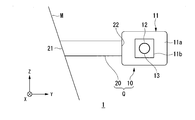
- FIG. 2 is a front view showing an example of the structural configuration of the peripheral information acquisition device 1.
- FIG. 3 is a plan view showing an example of a structural configuration of the peripheral information acquisition device 1.
- the structural arrangement of the peripheral information acquisition device 1 will be described with reference to FIGS.
- peripheral information acquisition device 1 on the driver's seat side (right side) will be described.
- the same thing is provided on the passenger seat side (left side) at a symmetrical position in the width direction of the vehicle M.
- the peripheral information acquisition device 1 includes, for example, an imaging unit 10 and a stay 20.
- the imaging unit 10 includes, for example, a camera housing 11 and a camera 12 built in the camera housing 11.
- the camera housing 11 is a housing for housing the camera 12.
- the camera housing 11 is formed, for example, in a streamlined shape or a shape with rounded corners so that air resistance is reduced in the traveling direction of the vehicle M.
- the camera housing 11 may be formed integrally with the stay 20. In this case, a portion of the camera housing 11 existing between the camera 10 and the vehicle may be integrally referred to as a stay 20.
- the camera housing 11 is not formed integrally with the stay 20, but is joined to the stay 20 by some means.
- the camera 12 is a digital camera using a solid-state imaging device such as a CCD (Charge Coupled Device) and a CMOS (Complementary Metal Oxide Semiconductor).
- the camera 12 may be an infrared camera that mainly detects infrared rays and forms an image.
- An opening 11d is provided on the rear surface 11c side of the camera housing 11 when viewed from the front side (forward direction side) of the vehicle M.
- the camera 12 is attached to the camera housing 11 so that the camera lens 13 can be visually recognized from the outside via the opening 11d.
- the camera 12 captures an image of the rear side of the vehicle M (hereinafter, the vehicle M may mean the vehicle body), for example.
- the rear side is, for example, a direction having an angle equal to or more than a predetermined angle (for example, about 10 degrees) from the side (side) of the vehicle M to the rear.
- the camera 12 is mounted in the camera housing 11 so that the optical axis faces rearward.
- the camera 12 captures an image of the inside of the space on the rear side at a predetermined viewing angle.
- the region captured by the camera 12 does not include a region on the side (left and right direction) of the vehicle M.
- the area on the side of the vehicle M may be monitored by another sensing device such as LIDAR (Light Detection and Ranging).
- FIG. 4 is a plan view illustrating an example of the first region R1.
- the first region R1 includes, for example, a part of the side surface MS of the vehicle M.
- the first region R1 includes, for example, blind spot regions X1 and X2 that become blind spots when viewed from the viewpoint E of the driver's seat.
- the blind spot areas X1 and X2 are generated by, for example, a B pillar between a front seat and a rear seat or a C pillar adjacent to a rear window.
- the first region R1 also includes a region that can be the blind spot XS of the side mirror viewed from the position of the driver's viewpoint E in the driver's seat S, assuming that the side mirror is installed.
- the first region R1 can be set with a wider viewing angle than the field of view obtained by the camera 12 with the side mirror.
- the camera 12 shows a blind spot generated by a pillar or the like of the vehicle M, but the viewing angle of the camera 12 is set to be wide in the vertical direction, and the driver side door D1 is provided in the first region R1.
- a blind spot generated by the side door D2 on the rear seat side may be included.
- the image captured by the camera 12 is displayed on the display unit 40.
- the camera 12 may be configured to image the front side of the vehicle M.
- the front side is, for example, a direction having an angle equal to or more than a predetermined angle (for example, about 10 degrees) from the side of the vehicle M (side) to the front side.
- the stay 20 is a support member for fixing the imaging unit 10 to the vehicle M.
- the base end 21 of the stay 20 is attached to an exterior part of the vehicle body of the vehicle M.
- the stay 20 is formed to have a streamlined cross section or a rounded corner so that air resistance is reduced in the traveling direction of the vehicle M.
- the camera housing 11 is attached to the tip 22 of the stay 20.
- the stay 20 is formed so that the camera housing 11 projects outward in the width direction (Y-axis direction) of the vehicle M.
- the camera housing 11 is fixed away from the vehicle M by the stay 20.
- the stay 20 comes into contact exclusively with the air flow on the surface of the vehicle M without disturbing the air flow on the surface of the vehicle M in the camera housing 11.
- the stay 20 since the stay 20 is formed in such a shape that the air resistance is reduced, the air resistance of the vehicle M can be reduced by these structures.
- the camera housing 11 can secure a field of view close to the door mirror by separating the stay 20 from the vehicle M, so that image processing of an image displayed on the display unit 40 becomes unnecessary or processing load is reduced. Can be done.
- structure Q A structure in which the imaging unit 10 and the stay 20 are combined (hereinafter, “structure Q”) can be attached to the vehicle M at various attachment positions. Hereinafter, this will be described.
- the structure Q is arranged on the vehicle M such that the outermost part of the structure Q is arranged inside the outermost part of the vehicle M.
- the outermost part of the structure Q is a position farthest from the center plane of the vehicle M in the width direction of the vehicle M. That is, the outermost part of the structure Q does not protrude outward from the outermost part in the width direction of the vehicle M.
- FIG. 5 is a front view illustrating a pattern of an attachment position of the structure Q.
- FIG. 6 is a perspective view illustrating a pattern of an attachment position of the structure Q.
- Q is attached to the A pillar MA of the vehicle M, for example.
- the A pillar MA is a pillar adjacent to the front window, among pillars connecting the vehicle body and the roof.
- the A-pillar MA is inclined, for example, in a direction in which the A-pillar MA falls behind the vehicle M when viewed from the side of the vehicle M.
- the A pillar MA is inclined, for example, in a direction in which the A pillar MA falls toward the center of the vehicle M when viewed from the front of the vehicle M.
- the first position W1 is located in the A-pillar MA, for example, near the base end of the A-pillar MA.
- the base end of the A-pillar MA is the root of the A-pillar MA standing upright from the frame of the vehicle M.
- a corner at the lower portion of the front window adjacent to the A-pillar MA or the side window P adjacent to the A-pillar MA Is a portion in contact with a corner at the lower part in the front direction of the front side.
- the vicinity of the base end of the A pillar MA includes the A pillar MA, the window frame of the side door, the side door, and the front fender F.
- the structure Q is visually recognized through the side window P from the viewpoint E at the seat S position.
- the viewpoint E is set so as to be included in a predetermined area above the seat S in consideration of, for example, individual differences between drivers.
- the predetermined area above the seat S is, for example, at a position overlapping the area of the headrest S1 of the seat S when viewed from the front side.
- the field of view and the blind spot from the viewpoint E at the position of the driver's seat are set to have a predetermined range width in a range viewed from each position within a predetermined region above the seat S. Therefore, the structure Q is disposed at a position that is visually recognized when viewed from each position included in a predetermined region in the region above the seat S in the driver's seat of the vehicle M.
- the structure Q is provided so as not to protrude from the outermost part in the width direction of the vehicle M.
- the structure Q is provided at a position visible to the driver, the driver can visually recognize the structure Q in the same manner as the current side mirror and can perform width adjustment and the like.
- M may protrude from the outermost part in the width direction of M.
- the structure Q may be provided so as to protrude from the outermost portion in the width direction of the vehicle M by giving priority to ensuring a view close to the side mirror of the camera 10.
- the driver When the driver performs a driving operation such as moving the vehicle M to the side of the wall, the driver can drive the vehicle M with the same feeling as looking at the side mirror with the visible structure Q as a mark. .
- the structure Q is attached to the second position W2.
- the second position W2 is, for example, a position lower than the first position W1 at the base end of the A pillar MA of the vehicle M.
- the second position W2 is disposed, for example, on the front fender F or the side door D1.
- the second position W2 is, for example, a position overlapping the fender F at the front of the vehicle M as viewed from the side.
- the fender F is, for example, a side panel at a front portion of the vehicle M on which a front wheel arch F1 is formed.
- an inclined surface having a non-perpendicular gradient is formed so as to cover the front wheel.
- the second position W2 is arranged, for example, in a region of the fender F where the inclined surface is formed.
- the outermost portion of the structure Q in the vehicle width direction is inside the outermost portion of the vehicle M in the vehicle width direction.
- the gradient is formed.
- the second position W2 is not limited to the region where the inclined surface is formed in the fender F, but may be disposed in another region.
- the second position W2 may be arranged on the driver's seat side door D1 or the rear seat side door D2, for example, if the outermost part of the structure Q does not exceed the outermost part of the vehicle M. Since the structure Q arranged at the second position W2 is arranged at a position where the driver becomes a blind spot from the viewpoint E of the driver, the structure Q is not visually recognized through the side window P.
- the structure Q is attached to the third position W3.
- the third position W3 is, for example, a position overlapping the fender F of the vehicle M as viewed from the side of the vehicle M.
- the third position W3 is located, for example, on the fender F on the front side of the vehicle M from the second position W2.
- the third position W3 is disposed on an inclined surface formed around the wheel arch F1 in the fender F, for example.
- the third position W3 is arranged in a blind spot area that is not visible from each position in the predetermined area including the viewpoint E. Since the structure Q arranged at the third position W3 is arranged at a position where the driver's viewpoint E becomes a blind spot, the structure Q is not visually recognized through the side window P.
- FIG. 7 is a diagram showing an example of an arrangement position of the structure Q as viewed from the driver's viewpoint E.
- FIG. 7 shows a first position W1, a second position W2, and a third position W3 in a state where the passenger seat side is viewed from the driver's seat.
- the display unit 40 is attached, for example, near the base end of the A-pillar MA in the vehicle interior. With such an arrangement, the display unit 40 can provide the driver with a driving sensation similar to a side mirror.
- the driver visually checks the display unit 40 so as to look at the side mirror and checks the environment on the rear side of the vehicle M. By visually recognizing the display content of the display unit 40, the driver can check the surrounding situation of the vehicle M with a feeling similar to that of the side mirror.
- the driver is given a sense of the position of the structure Q projecting in the width direction of the vehicle M. is necessary.
- the driver drives the vehicle M without the side mirror
- the driver can move the vehicle M to the wall side by the amount without the side mirror as compared with driving the vehicle M with the side mirror. It has been empirically known that a driver who drives a vehicle having no vehicle has anxiety when the image capturing unit 10 and the like are installed at a position where the vehicle cannot be seen because there is no outermost vehicle visible.
- the driver can adjust the width as compared with the case where there is a side mirror without feeling the above-mentioned feeling of anxiety.
- a mark as described later is displayed to make the driver aware of the outermost part of the vehicle M, anxiety of the driver can be reduced.
- FIG. 8 is a diagram showing an example of the image IM1 displayed on the display unit 40.
- the image IM1 is displayed on the display unit 40 including the outermost part of the vehicle M on the image to assist the driver in the sense of the vehicle. For example, when the outermost part of the vehicle M is the wheel arch of the rear fender, the display unit 40 displays the first region R1 so as to include the wheel arch.
- the display unit 40 displays the position on the outermost image in the width direction of the vehicle M in order to assist the driver in the vehicle sense. May be displayed together with the image IM1.
- the display unit 40 displays an image IM1 in which auxiliary marks are superimposed on the image captured by the imaging unit 10.
- the display of the auxiliary mark is, for example, a display in which a position corresponding to the outermost part of the vehicle M is superimposed on a road surface in an image captured by the imaging unit 10 with a straight line L or the like.
- the auxiliary mark may be displayed in any display form as long as the outermost position of the vehicle M can be determined, such as not only the straight line L, but also a point, an arrow, and a colored area.
- auxiliary mark such as a straight line offset by a predetermined width from the outermost part may be displayed on the display unit 40.
- the other auxiliary mark may be arbitrarily displayed on the display unit 40 according to the setting of the user.
- auxiliary marks such as the outermost part of the vehicle M and the straight line L on the image of the display unit 40
- the driver cannot visually recognize the outermost part in the width direction of the vehicle M.
- This also makes it easy to adjust the width, and can perform a driving operation such as adjusting the width without feeling uneasy about the distance between the vehicle M and the wall or the like.
- peripheral information acquisition device 1 it is possible to provide a driving environment in which the driver does not feel uncomfortable with the vehicle.
- the peripheral information acquisition device 1 when the structure Q is arranged at a position where the side mirror is arranged, it is possible to provide a driving environment equivalent to that of the side mirror.
- the peripheral information acquisition device 1 when the structure Q is arranged at a position that cannot be seen from the driver's seat, a wider field of view of the driver from the side window P can be secured.
- the peripheral information acquisition device 1 by displaying auxiliary marks such as the outermost part of the vehicle M and the straight line L on the display unit 40, a driving environment that supports the driver's driving feeling is provided. can do.
- FIG. 9 is a plan view illustrating an example of an attachment position of a structure Q according to a modification.
- a vehicle M in which the fender F and the side door D1 are nearly vertical it may be difficult to determine the position where the structure Q is attached to the fender F or the side door D1.
- the width of the fender F and the side door D1 may be the outermost of the vehicle or a width close thereto.
- the structure Q on the fender F and the side door D1 of the vehicle M so as not to protrude from the outermost portion of the vehicle. Therefore, in the vehicle M as described above, it is necessary to arrange the structure Q at a position other than the fender F and the side door D1.
- the structure Q according to the modification is attached to the A pillar MA.
- the A pillar MA is inclined rearward as seen from the side of the vehicle M, and is inclined in a direction falling inward as seen from the front of the vehicle M.
- the structure Q is arranged in the middle of the A pillar MA. In such a position, the structure Q is arranged so as not to protrude from the outermost part of the vehicle M. Further, the structure Q is disposed in a blind spot area XP generated by the A pillar MA when viewed from the viewpoint E of the driver in the vehicle. The structure Q is set to a position in the blind spot area XP that is not visible from each position in the predetermined area including the viewpoint E.
- the stay 20 is attached to the A-pillar MA to support the imaging unit 10, and is formed so that the structure Q is accommodated in the blind spot area XP.
- the field of view of the side window P is ensured when viewed from the driver's viewpoint E.
- the imaging unit 10 can image the surrounding environment on the front side and the rear side of the vehicle M without the structure Q protruding outside the vehicle M.
- the structure Q arranged at the first position W1 is visible from the driver's viewpoint E.
- the structure Q is arranged in a blind spot area from the viewpoint E, not in an area visible from the viewpoint E of the driver, and a head-up display or the like is provided so as to assist the driver in the sense of vehicle width.
- a virtual image of a mark such as an auxiliary line may be displayed at a position visible from the driver's viewpoint through the side window P.
- the virtual image of the mark corresponds to the outermost position in the width direction of the vehicle M when viewed from a predetermined area including the viewpoint E, and is displayed so as to be superimposed on the field of view seen through the side window P.
- the driver can perform the driving operation with the mark appearing in the side window P as a target.
- DESCRIPTION OF SYMBOLS 1 Peripheral information acquisition device, 10 ... Imaging part, 11 ... Camera housing, 11c ... Back surface, 11d ... Opening, 12 ... Camera, 13 ... Camera lens, 20 ... Stay, 21 ... Base end, 22 ... Front end, 30 ... Information acquisition unit, 40 display unit, 50 display control unit, D1 side door, D2 side door, EL organic, F fender, F1 wheel arch, IM1 image, L line, M vehicle MA A pillar, MB B pillar, MC C pillar, P side window, Q structure, S seat, S2 headrest, W1 first position, W2 second position, W3 third position
Abstract
This invention is a peripheral information acquisition device comprising an imaging unit for imaging the area frontward or rearward of a vehicle, and a stay for supporting the imaging unit on the vehicle. The stay is formed so as to cause the imaging unit to project outwards in the width direction of the vehicle from a side surface of the vehicle. A structure that includes the imaging unit and the stay is such that the outermost part of the structure in the width direction of the vehicle is disposed more inward in the width direction of the vehicle than the outermost part of the vehicle in the width direction.
Description
本発明は、周辺情報取得装置および車両に関する。
The present invention relates to a peripheral information acquisition device and a vehicle.
車両のサイドミラーを廃止して、カメラにより撮像された画像を表示することで、サイドミラーの代替とする技術が検討されている。これに関連する技術として、特許文献1に記載された技術が知られている。特許文献1に記載された技術は、サイドミラーの下部にカメラを配置して車両の側方領域を撮像し、撮像により得られた画像を表示部に表示するものである。
技術 Technology to replace the side mirrors by eliminating the side mirrors of vehicles and displaying images taken by cameras is being studied. As a technique related to this, a technique described in Patent Document 1 is known. The technique described in Patent Literature 1 is to arrange a camera below a side mirror to capture an image of a side area of a vehicle, and to display an image obtained by the imaging on a display unit.
サイドミラーを廃止してカメラ画像のみを用いる場合、サイドミラーが取り付けられていた位置以外に、カメラをどのように配置するか、検討が十分になされていない。
廃 止 In the case where the side mirror is abolished and only the camera image is used, not enough consideration has been given to how to arrange the camera except for the position where the side mirror was attached.
この点、特許文献1に記載された技術では、サイドミラーにカメラを配置して、サイドミラーで得られる鏡像の視界に加えて、カメラによって撮像されて得られた映像を用いて補助的な視界を確保しているが、サイドミラーを廃止することについては考慮されていない。
In this regard, in the technology described in Patent Literature 1, a camera is arranged on a side mirror, and in addition to a field of view of a mirror image obtained by the side mirror, an auxiliary field of view is obtained by using an image obtained by imaging with the camera. However, it is not considered to abolish the side mirror.
本発明は、このような事情を考慮してなされたものであり、運転者の車両感覚に違和感を与えない周辺情報取得装置および車両を提供することを目的の一つとする。
The present invention has been made in view of such circumstances, and an object of the present invention is to provide a peripheral information acquisition device and a vehicle that do not give a driver a sense of incompatibility with the vehicle.
この発明に係る周辺情報取得装置は、以下の構成を採用した。
(1):この発明の一態様に係る周辺情報取得装置は、車両の前側方または後側方を撮像する撮像部と、前記撮像部を前記車両に支持するためのステイと、を備え、前記ステイは、前記撮像部を、前記車両の側面から前記車両の幅方向に関して外方に向かって突出させるように形成され、前記撮像部および前記ステイを含む構造体は、前記車両の幅方向に関する前記構造体の最外部が前記車両の幅方向に関する最外部よりも前記車両の幅方向に関して内側に配置される、周辺情報取得装置である。 The peripheral information acquisition device according to the present invention employs the following configuration.
(1): A peripheral information acquisition device according to an aspect of the present invention includes: an imaging unit that images a front side or a rear side of a vehicle; and a stay that supports the imaging unit on the vehicle. The stay is formed so that the imaging unit projects outward from a side surface of the vehicle with respect to a width direction of the vehicle, and the structure including the imaging unit and the stay includes A peripheral information acquisition device, wherein the outermost part of the structure is disposed inside the outermost part in the width direction of the vehicle with respect to the outermost part in the width direction of the vehicle.
(2):上記(1)の態様において、前記撮像部は、前記ステイを介して、前記車両の運転席におけるシート上部の領域にある所定の位置から見て死角となる領域に配置されるものである。
(2): In the aspect of (1), the imaging unit is disposed in a blind spot area of the driver's seat of the vehicle from a predetermined position in an upper area of the seat via the stay. It is.
(3):上記(2)の態様において、前記撮像部は、前記ステイを介して、前記車両の運転席におけるシート上部の領域にある所定領域内に含まれる各位置から見て死角となる領域に配置されるものである。
(3): In the above aspect (2), the imaging unit may be, through the stay, a blind spot when viewed from each position included in a predetermined region in a region above a seat in a driver's seat of the vehicle. It is arranged in.
(4):上記(1)から(3)のうちいずれか一つの態様において、前記撮像部は、前記ステイを介して、サイドミラーを有さない前記車両に取り付けられ、前記車両の後部の側面を含む後側方を撮像するものである。
(4): In any one of the above aspects (1) to (3), the imaging unit may be attached to the vehicle without a side mirror via the stay, and a rear side surface of the vehicle. The image of the rear side including is captured.
(5):上記(1)から(4)のうちいずれか一つの態様において、前記撮像部は、前記ステイを介して、前記車両のフロントウィンドウに隣接するピラーに配置されるものである。
(5): In any one of the above modes (1) to (4), the imaging unit is disposed on a pillar adjacent to a front window of the vehicle via the stay.
(6):上記(5)の態様において、前記撮像部は、前記ステイを介して、前記ピラーにより生じる死角領域内において前記ピラーに配置されるものである。
(6): In the aspect of the above (5), the imaging unit is arranged on the pillar via the stay in a blind spot area generated by the pillar.
(7):上記(1)から(4)のうちいずれかの態様において、前記撮像部は、前記ステイを介して、前記車両の前部のフェンダーにおける垂直でない傾斜面に配置されるものである。
(7): In any one of the above aspects (1) to (4), the imaging unit is arranged on a non-perpendicular inclined surface of a fender at a front part of the vehicle via the stay. .
(9):上記(1)から(7)のうちいずれかの態様において、前記撮像部により撮像された画像を表示する表示部を更に備え、前記表示部は、前記車両の側面の一部または前記車両の幅方向に関する最外部の画像上の位置を示す目印を、前記画像と共に表示するものである。
(9): In any one of the above aspects (1) to (7), further comprising a display unit that displays an image captured by the imaging unit, wherein the display unit is a part of a side surface of the vehicle or A mark indicating a position on the outermost image in the width direction of the vehicle is displayed together with the image.
(9):この発明の一態様に係る車両は、車体の前側方または後側方を撮像する撮像部と、前記撮像部を前記車体に支持するためのステイと、を備え、前記ステイは、前記撮像部を、前記車体の側面から前記車体の幅方向に関して外方に向かって突出させるように形成され、前記撮像部および前記ステイを含む構造体は、前記車体の幅方向に関する前記構造体の最外部が前記車体の幅方向に関する最外部よりも前記車体の幅方向に関して内側に配置される、車両。
(9): A vehicle according to one aspect of the present invention includes: an imaging unit that images a front side or a rear side of a vehicle body; and a stay for supporting the imaging unit on the vehicle body. The imaging unit is formed so as to protrude outward from the side surface of the vehicle body in the width direction of the vehicle body, and the structure including the imaging unit and the stay is a structure of the structure body in the width direction of the vehicle body. The vehicle, wherein the outermost part is disposed on the inner side in the width direction of the vehicle body than the outermost part in the width direction of the vehicle body.
(1)~(9)によれば、運転者の車両感覚に違和感を与えない運転環境を提供することができる。
According to (1) to (9), it is possible to provide a driving environment in which the driver does not feel uncomfortable with the vehicle.
(2)、(3)、(6)、(7)によれば、運転席からの視界を確保することができる。
According to (2), (3), (6), and (7), the field of view from the driver's seat can be secured.
(4)、(8)によれば、運転者に車幅方向の車両感覚を与えることができる。
According to (4) and (8), the driver can be given a vehicle sense in the vehicle width direction.
以下、図面を参照し、本発明の周辺情報取得装置の実施形態について説明する。以下、車両は右ハンドル車であるものとして説明するが、左ハンドル車については以下の説明内容において適宜、左右を読み替えればよい。
Hereinafter, an embodiment of the peripheral information acquisition device of the present invention will be described with reference to the drawings. Hereinafter, the vehicle will be described as being a right-hand drive vehicle, but the left-hand drive vehicle may be replaced with left and right as appropriate in the following description.
図1は、周辺情報取得装置1の構成の一例を示すブロック図である。周辺情報取得装置1は、撮像部10と、情報取得部30と、表示部40と、表示制御部50とを備える。撮像部10は、カメラにより車両Mの前側方または後側方を含む空間を撮像する。撮像部10は、撮像した画像のデータを情報取得部30に出力する。
FIG. 1 is a block diagram showing an example of the configuration of the peripheral information acquisition device 1. The peripheral information acquisition device 1 includes an imaging unit 10, an information acquisition unit 30, a display unit 40, and a display control unit 50. The imaging unit 10 captures an image of a space including a front side or a rear side of the vehicle M by a camera. The imaging unit 10 outputs data of the captured image to the information acquisition unit 30.
情報取得部30は、撮像部10から取得した画像のデータを表示制御部50に出力する。表示制御部50は、情報取得部30から取得した画像のデータに基づいて表示部40に撮像部10が撮像した画像に基づく画像を表示させる。
The information acquisition unit 30 outputs the data of the image acquired from the imaging unit 10 to the display control unit 50. The display control unit 50 causes the display unit 40 to display an image based on the image captured by the imaging unit 10 based on the image data acquired from the information acquisition unit 30.
表示制御部50は、CPU(Central Processing Unit)などのプロセッサがプログラム(ソフトウェア)を実行することで実現される。表示制御部50は、LSI(Large Scale Integration)やASIC(Application Specific Integrated Circuit)、FPGA(Field-Programmable Gate Array)などのハードウェアによって実現されてもよいし、ソフトウェアとハードウェアの協働によって実現されてもよい。
The display control unit 50 is realized by a processor such as a CPU (Central Processing Unit) executing a program (software). The display control unit 50 may be realized by hardware such as an LSI (Large Scale Integration), an ASIC (Application Specific Integrated Circuit), or an FPGA (Field-Programmable Gate Array), or realized by cooperation of software and hardware. May be done.
表示部40は、例えば、液晶ディスプレイ、有機ELディスプレイなどにより実現される。
The display unit 40 is realized by, for example, a liquid crystal display, an organic EL display, or the like.
図2は、周辺情報取得装置1の構造的な構成の一例を示す正面図である。図3は、周辺情報取得装置1の構造的な構成の一例を示す平面図である。以下、図2および図3を参照して周辺情報取得装置1の構造的な配置関係について説明する。
FIG. 2 is a front view showing an example of the structural configuration of the peripheral information acquisition device 1. FIG. 3 is a plan view showing an example of a structural configuration of the peripheral information acquisition device 1. Hereinafter, the structural arrangement of the peripheral information acquisition device 1 will be described with reference to FIGS.
以下、運転席側(右側)の周辺情報取得装置1について説明するが、助手席側(左側)にも、車両Mの幅方向に関する対称の位置に同様のものが設けられる。
Hereinafter, the peripheral information acquisition device 1 on the driver's seat side (right side) will be described. The same thing is provided on the passenger seat side (left side) at a symmetrical position in the width direction of the vehicle M.
周辺情報取得装置1は、例えば、撮像部10と、ステイ20とを備える。
The peripheral information acquisition device 1 includes, for example, an imaging unit 10 and a stay 20.
撮像部10は、例えば、カメラハウジング11と、カメラハウジング11に内蔵されたカメラ12とを備える。カメラハウジング11は、カメラ12を内蔵するための筐体である。カメラハウジング11は、例えば、車両Mの進行方向に対して空気抵抗が軽減されるように流線型形状や、角部に丸みを持たせた形状に形成されている。カメラハウジング11は、ステイ20と一体に形成されていてもよい。この場合、カメラハウジング11のカメラ10と車両間に存在する部分を一体にしてステイ20と呼んでもよい。
The imaging unit 10 includes, for example, a camera housing 11 and a camera 12 built in the camera housing 11. The camera housing 11 is a housing for housing the camera 12. The camera housing 11 is formed, for example, in a streamlined shape or a shape with rounded corners so that air resistance is reduced in the traveling direction of the vehicle M. The camera housing 11 may be formed integrally with the stay 20. In this case, a portion of the camera housing 11 existing between the camera 10 and the vehicle may be integrally referred to as a stay 20.
以下の説明では、カメラハウジング11は、ステイ20と一体に形成されておらず、何らかの手段でステイ20と接合されているものとする。
In the following description, it is assumed that the camera housing 11 is not formed integrally with the stay 20, but is joined to the stay 20 by some means.
カメラ12は、例えば、CCD(Charge Coupled Device)やCMOS(Complementary Metal Oxide Semiconductor)等の固体撮像素子を利用したデジタルカメラである。カメラ12は、主に赤外線を検出して画像化する赤外線カメラであってもよい。
The camera 12 is a digital camera using a solid-state imaging device such as a CCD (Charge Coupled Device) and a CMOS (Complementary Metal Oxide Semiconductor). The camera 12 may be an infrared camera that mainly detects infrared rays and forms an image.
車両Mの正面側(前進方向側)から見てカメラハウジング11の背面11c側には、開口部11dが設けられている。カメラ12は、カメラレンズ13が開口部11dを介して外部から視認可能なようにカメラハウジング11に取り付けられている。
An opening 11d is provided on the rear surface 11c side of the camera housing 11 when viewed from the front side (forward direction side) of the vehicle M. The camera 12 is attached to the camera housing 11 so that the camera lens 13 can be visually recognized from the outside via the opening 11d.
カメラ12は、例えば、車両M(以下、車両Mは車体を意味する場合もある)の後側方を撮像する。後側方とは、例えば、車両Mの真横(側方)から後方側に所定角度(例えば10度程度)以上の角度をもった方向である。カメラ12は、光軸が後側方を向くようにカメラハウジング11内に取り付けられている。
The camera 12 captures an image of the rear side of the vehicle M (hereinafter, the vehicle M may mean the vehicle body), for example. The rear side is, for example, a direction having an angle equal to or more than a predetermined angle (for example, about 10 degrees) from the side (side) of the vehicle M to the rear. The camera 12 is mounted in the camera housing 11 so that the optical axis faces rearward.
カメラ12は、後側方における空間内を所定の視野角で撮像する。カメラ12が撮像する領域には、車両Mの側方(左右方向)の領域は含まれない。車両Mの側方の領域は、例えば、LIDAR(Light Detection and Ranging)等の他のセンシング機器により監視されてよい。
The camera 12 captures an image of the inside of the space on the rear side at a predetermined viewing angle. The region captured by the camera 12 does not include a region on the side (left and right direction) of the vehicle M. The area on the side of the vehicle M may be monitored by another sensing device such as LIDAR (Light Detection and Ranging).
カメラ12が撮像する後側方の範囲を第1領域R1とする。図4は、第1領域R1の一例を示す平面図である。第1領域R1は、例えば、車両Mの側面MSの一部を含む。
後 A rear side range where the camera 12 captures an image is defined as a first region R1. FIG. 4 is a plan view illustrating an example of the first region R1. The first region R1 includes, for example, a part of the side surface MS of the vehicle M.
第1領域R1は、例えば、運転席の視点Eから見て死角となる死角領域X1,X2を含む。死角領域X1,X2は、例えば、前部座席と後部座席の間にあるBピラーや、リヤウィンドウに隣接したCピラーにより生じるものである。第1領域R1には、サイドミラーが設置されていると仮定した場合に、運転席のシートSにおける運転者の視点Eの位置から見たサイドミラーの死角XSとなり得る領域も含まれる。
The first region R1 includes, for example, blind spot regions X1 and X2 that become blind spots when viewed from the viewpoint E of the driver's seat. The blind spot areas X1 and X2 are generated by, for example, a B pillar between a front seat and a rear seat or a C pillar adjacent to a rear window. The first region R1 also includes a region that can be the blind spot XS of the side mirror viewed from the position of the driver's viewpoint E in the driver's seat S, assuming that the side mirror is installed.
第1領域R1は、カメラ12によりサイドミラーにより得られる視界よりも広い視野角で設定可能である。例えば、図4では、カメラ12は、車両Mのピラー等により生じる死角を示していたが、カメラ12の視野角を上下方向に広く設定して、第1領域R1に運転席側のサイドドアD1や、後席側のサイドドアD2により生じる死角も含められるようにしてもよい。カメラ12により撮像された画像は、表示部40に表示される。
The first region R1 can be set with a wider viewing angle than the field of view obtained by the camera 12 with the side mirror. For example, in FIG. 4, the camera 12 shows a blind spot generated by a pillar or the like of the vehicle M, but the viewing angle of the camera 12 is set to be wide in the vertical direction, and the driver side door D1 is provided in the first region R1. Alternatively, a blind spot generated by the side door D2 on the rear seat side may be included. The image captured by the camera 12 is displayed on the display unit 40.
カメラ12は、車両Mの前側方を撮像するものであってもよい。前側方とは、例えば、車両Mの真横(側方)から前方側に所定角度(例えば10度程度)以上の角度をもった方向である。
The camera 12 may be configured to image the front side of the vehicle M. The front side is, for example, a direction having an angle equal to or more than a predetermined angle (for example, about 10 degrees) from the side of the vehicle M (side) to the front side.
ステイ20は、撮像部10を車両Mに固定するための支持部材である。ステイ20の基端21は、車両Mの車体の外装部分に取り付けられている。ステイ20は、車両Mの進行方向に対して空気抵抗が軽減されるように、断面が流線型形状や、角部に丸みを持たせた形状となるように形成されている。
The stay 20 is a support member for fixing the imaging unit 10 to the vehicle M. The base end 21 of the stay 20 is attached to an exterior part of the vehicle body of the vehicle M. The stay 20 is formed to have a streamlined cross section or a rounded corner so that air resistance is reduced in the traveling direction of the vehicle M.
ステイ20の先端22には、カメラハウジング11が取り付けられている。ステイ20は、カメラハウジング11を、車両Mの幅方向(Y軸方向)に関して外方に向かって突出させるように形成されている。カメラハウジング11は、ステイ20により、車両Mから離間して固定される。
The camera housing 11 is attached to the tip 22 of the stay 20. The stay 20 is formed so that the camera housing 11 projects outward in the width direction (Y-axis direction) of the vehicle M. The camera housing 11 is fixed away from the vehicle M by the stay 20.
これにより、カメラハウジング11は、車両Mの表面の空気の流れを乱すことなく、専らステイ20が車両Mの表面の空気の流れに接することになる。前述したように、ステイ20は空気抵抗が軽減されるような形状に形成されているため、これらの構造によって、車両Mの空気抵抗を低減することができる。さらにカメラハウジング11は、車両Mからステイ20を離間させることにより、ドアミラーに近い視界を確保することが可能であり、表示部40に表示される画像の画像処理を不要とし、または処理負荷を低減させることができる。
Accordingly, the stay 20 comes into contact exclusively with the air flow on the surface of the vehicle M without disturbing the air flow on the surface of the vehicle M in the camera housing 11. As described above, since the stay 20 is formed in such a shape that the air resistance is reduced, the air resistance of the vehicle M can be reduced by these structures. Further, the camera housing 11 can secure a field of view close to the door mirror by separating the stay 20 from the vehicle M, so that image processing of an image displayed on the display unit 40 becomes unnecessary or processing load is reduced. Can be done.
撮像部10とステイ20とを合わせた構造体(以下、「構造体Q」)は、車両Mにおいて様々な取り付け位置に取り付け可能である。以下、これについて説明する。
構造 A structure in which the imaging unit 10 and the stay 20 are combined (hereinafter, “structure Q”) can be attached to the vehicle M at various attachment positions. Hereinafter, this will be described.
構造体Qは、自体の最外部が、車両Mの最外部よりも内側に配置されるよう車両Mに配置される。構造体Qの最外部とは、車両Mの幅方向に関して、車両Mの中心面から最も遠い位置である。つまり、構造体Qの最外部は、車両Mの幅方向に関する最外部から外側にはみ出さない。
The structure Q is arranged on the vehicle M such that the outermost part of the structure Q is arranged inside the outermost part of the vehicle M. The outermost part of the structure Q is a position farthest from the center plane of the vehicle M in the width direction of the vehicle M. That is, the outermost part of the structure Q does not protrude outward from the outermost part in the width direction of the vehicle M.
図5は、構造体Qの取り付け位置のパターンを例示した正面図である。図6は、構造体Qの取り付け位置のパターンを例示した斜視図である。
FIG. 5 is a front view illustrating a pattern of an attachment position of the structure Q. FIG. 6 is a perspective view illustrating a pattern of an attachment position of the structure Q.
第1の例では、Qは、例えば、車両MのAピラーMAに取り付けられる。AピラーMAは、車体とルーフを接続するピラーのうち、フロントウィンドウに隣接するピラーである。AピラーMAは、例えば、車両Mの側面方向から見て車両Mの後ろ側に倒れる方向に傾斜している。AピラーMAは、例えば、車両Mの正面方向から見て車両Mの中央側に倒れる方向に傾斜している。
で は In the first example, Q is attached to the A pillar MA of the vehicle M, for example. The A pillar MA is a pillar adjacent to the front window, among pillars connecting the vehicle body and the roof. The A-pillar MA is inclined, for example, in a direction in which the A-pillar MA falls behind the vehicle M when viewed from the side of the vehicle M. The A pillar MA is inclined, for example, in a direction in which the A pillar MA falls toward the center of the vehicle M when viewed from the front of the vehicle M.
第1位置W1は、AピラーMAにおいて、例えば、AピラーMAの基端の近傍に配置される。AピラーMAの基端とは、車両Mのフレームから起立したAピラーMAの根本であり、例えば、AピラーMAに隣接するフロントウィンドウの下部における角部や、AピラーMAに隣接するサイドウィンドウPの前方向の下部における角部に接する部分である。
The first position W1 is located in the A-pillar MA, for example, near the base end of the A-pillar MA. The base end of the A-pillar MA is the root of the A-pillar MA standing upright from the frame of the vehicle M. For example, a corner at the lower portion of the front window adjacent to the A-pillar MA or the side window P adjacent to the A-pillar MA Is a portion in contact with a corner at the lower part in the front direction of the front side.
AピラーMAの基端の近傍とは、例えば、基端から所定範囲内(例えば数十[cm]以内)をいう。この結果、AピラーMAの基端の近傍には、AピラーMA、サイドドアの窓枠、サイドドア、および前部のフェンダーFが含まれる。
近 傍 Near the base end of the A pillar MA means, for example, within a predetermined range (for example, within several tens [cm]) from the base end. As a result, the vicinity of the base end of the A pillar MA includes the A pillar MA, the window frame of the side door, the side door, and the front fender F.
第1位置W1に構造体Qが取り付けられた場合、構造体Qは、シートS位置における視点Eから、サイドウィンドウP越しに視認される。視点Eは、例えば、運転者の個人差を考慮して、シートS上部の所定領域に含まれるように設定される。シートS上部の所定領域は、例えば、正面側から見てシートSのヘッドレストS1の領域に重なる位置にある。
場合 When the structure Q is attached to the first position W1, the structure Q is visually recognized through the side window P from the viewpoint E at the seat S position. The viewpoint E is set so as to be included in a predetermined area above the seat S in consideration of, for example, individual differences between drivers. The predetermined area above the seat S is, for example, at a position overlapping the area of the headrest S1 of the seat S when viewed from the front side.
運転席の位置における視点Eからの視界および死角は、シートS上部の所定領域内の各位置から見た範囲において、所定範囲の幅をもって設定される。従って、構造体Qは、車両Mの運転席におけるシートS上部の領域にある所定領域内に含まれる各位置から見て視認される位置に配置される。
視 The field of view and the blind spot from the viewpoint E at the position of the driver's seat are set to have a predetermined range width in a range viewed from each position within a predetermined region above the seat S. Therefore, the structure Q is disposed at a position that is visually recognized when viewed from each position included in a predetermined region in the region above the seat S in the driver's seat of the vehicle M.
第1の例において、構造体Qは、車両Mの幅方向に関する最外部からはみ出さないように設けられているものとした。しかし、運転者から視認できる位置に構造体Qが設けられているのであれば、運転者は現状のサイドミラーと同様に視認でき、幅寄せ等を行うことができるため、構造体Qは、車両Mの幅方向に関する最外部からはみ出して設けられていてもよい。また、構造体Qは、カメラ10がサイドミラーと近い視界を確保することを優先することにより、車両Mの幅方向に関する最外部からはみ出して設けられていてもよい。
In the first example, the structure Q is provided so as not to protrude from the outermost part in the width direction of the vehicle M. However, if the structure Q is provided at a position visible to the driver, the driver can visually recognize the structure Q in the same manner as the current side mirror and can perform width adjustment and the like. M may protrude from the outermost part in the width direction of M. In addition, the structure Q may be provided so as to protrude from the outermost portion in the width direction of the vehicle M by giving priority to ensuring a view close to the side mirror of the camera 10.
運転者は、車両Mを壁際に幅寄せさせる等の運転操作を行う場合、視認可能な構造体Qを目印にして、サイドミラーを見る感覚と同じような感覚で車両Mを運転することができる。
When the driver performs a driving operation such as moving the vehicle M to the side of the wall, the driver can drive the vehicle M with the same feeling as looking at the side mirror with the visible structure Q as a mark. .
第2の例では、構造体Qは、第2位置W2に取り付けられている。第2位置W2は、例えば、車両MのAピラーMAの基端の第1位置W1よりも低い位置にある。第2位置W2は、例えば、前部のフェンダーFやサイドドアD1に配置される。
で は In the second example, the structure Q is attached to the second position W2. The second position W2 is, for example, a position lower than the first position W1 at the base end of the A pillar MA of the vehicle M. The second position W2 is disposed, for example, on the front fender F or the side door D1.
第2位置W2は、例えば、側面から見て車両Mの前部のフェンダーFに重なる位置にある。フェンダーFは、例えば、フロントのホイールアーチF1が形成された車両Mの前部における側面のパネルである。フェンダーFは、例えば、フロントホイールを覆うように垂直でない勾配を有する傾斜面が形成されている。第2位置W2は、例えば、フェンダーFにおいて傾斜面が形成された領域に配置される。
The second position W2 is, for example, a position overlapping the fender F at the front of the vehicle M as viewed from the side. The fender F is, for example, a side panel at a front portion of the vehicle M on which a front wheel arch F1 is formed. In the fender F, for example, an inclined surface having a non-perpendicular gradient is formed so as to cover the front wheel. The second position W2 is arranged, for example, in a region of the fender F where the inclined surface is formed.
フェンダーFの傾斜面には、構造体Qが第2位置W2に取り付けられた状態において、構造体Qの車幅方向の最外部が、車両Mの車幅方向の最外部よりも内側になるような勾配が形成されている。
On the inclined surface of the fender F, when the structure Q is attached to the second position W2, the outermost portion of the structure Q in the vehicle width direction is inside the outermost portion of the vehicle M in the vehicle width direction. The gradient is formed.
第2位置W2は、フェンダーFにおいて傾斜面が形成された領域にされるのではなく、他の領域に配置されてもよい。第2位置W2は、例えば、構造体Qの最外部が車両Mの最外部を超えないのであれば、運転席側のサイドドアD1や後席のサイドドアD2に配置されてもよい。第2位置W2に配置された構造体Qは、運転者の視点Eから死角となる位置に配置されるため、サイドウィンドウP越しに視認されない。
The second position W2 is not limited to the region where the inclined surface is formed in the fender F, but may be disposed in another region. The second position W2 may be arranged on the driver's seat side door D1 or the rear seat side door D2, for example, if the outermost part of the structure Q does not exceed the outermost part of the vehicle M. Since the structure Q arranged at the second position W2 is arranged at a position where the driver becomes a blind spot from the viewpoint E of the driver, the structure Q is not visually recognized through the side window P.
第2位置W2に構造体Qが取り付けられた場合、サイドウィンドウPからの視界は、構造体Qによって遮られずに広くなる。
場合 When the structure Q is attached to the second position W2, the field of view from the side window P is widened without being blocked by the structure Q.
第3の例では、構造体Qは第3位置W3に取り付けられている。第3位置W3は、例えば、車両Mの側方から見て車両MのフェンダーFに重なる位置にある。第3位置W3は、例えば、フェンダーFにおいて第2位置W2より車両Mの前方側に配置されている。
で は In the third example, the structure Q is attached to the third position W3. The third position W3 is, for example, a position overlapping the fender F of the vehicle M as viewed from the side of the vehicle M. The third position W3 is located, for example, on the fender F on the front side of the vehicle M from the second position W2.
第3位置W3は、例えば、フェンダーFにおいてホイールアーチF1の周囲に形成された傾斜面に配置される。第3位置W3は、視点Eが含まれる所定領域における各位置から視認されない死角領域内に配置される。第3位置W3に配置された構造体Qは、運転者の視点Eから死角となる位置に配置されるため、サイドウィンドウP越しに視認されない。
The third position W3 is disposed on an inclined surface formed around the wheel arch F1 in the fender F, for example. The third position W3 is arranged in a blind spot area that is not visible from each position in the predetermined area including the viewpoint E. Since the structure Q arranged at the third position W3 is arranged at a position where the driver's viewpoint E becomes a blind spot, the structure Q is not visually recognized through the side window P.
第3位置W3に構造体Qが取り付けられた場合、サイドウィンドウPからの視界は、構造体Qによって遮られずに広くなる。
場合 When the structure Q is attached to the third position W3, the field of view from the side window P is widened without being blocked by the structure Q.
図7は、運転者の視点Eから見た構造体Qの配置位置の一例を示す図である。図7には、運転席から助手席側を見た状態における第1位置W1、第2位置W2および第3位置W3が示されている。
FIG. 7 is a diagram showing an example of an arrangement position of the structure Q as viewed from the driver's viewpoint E. FIG. 7 shows a first position W1, a second position W2, and a third position W3 in a state where the passenger seat side is viewed from the driver's seat.
表示部40は、例えば、車室内においてAピラーMAの基端の近傍に取り付けられている。係る配置により、表示部40は、運転者にサイドミラーと似た運転感覚を提供することができる。運転者はサイドミラーを見るように表示部40を視認して車両Mの後側方の環境を確認する。運転者は、表示部40の表示内容を視認することにより、サイドミラーと同じような感覚で車両Mの周辺状況を確認することができる。
The display unit 40 is attached, for example, near the base end of the A-pillar MA in the vehicle interior. With such an arrangement, the display unit 40 can provide the driver with a driving sensation similar to a side mirror. The driver visually checks the display unit 40 so as to look at the side mirror and checks the environment on the rear side of the vehicle M. By visually recognizing the display content of the display unit 40, the driver can check the surrounding situation of the vehicle M with a feeling similar to that of the side mirror.
上述したように、第2位置W2または第3位置W3においては構造体QがサイドウィンドウPから視認されないので、運転者に、車両Mの幅方向に突出した構造体Qの位置の感覚を与えることが必要である。
As described above, since the structure Q is not visible from the side window P at the second position W2 or the third position W3, the driver is given a sense of the position of the structure Q projecting in the width direction of the vehicle M. is necessary.
特に、車両Mを壁際に寄せる等の幅寄せ運転をする際、サイドミラーの有無が運転者の運転感覚に与える影響を考慮する必要がある。運転者が、サイドミラーの無い車両Mを運転する際、サイドミラーがある車両Mを運転する場合に比してサイドミラーが無い分、車両Mを壁側に寄せることができるが、サイドミラーが無い車両を運転する運転者は、視認可能な車両最外部が無いことにより、撮像部10等が見えない位置に設置されていると不安感を感じるということが経験的に知られている。
Especially, it is necessary to consider the influence of the presence or absence of the side mirror on the driving sensation of the driver when driving the vehicle M to the side of the wall, for example. When the driver drives the vehicle M without the side mirror, the driver can move the vehicle M to the wall side by the amount without the side mirror as compared with driving the vehicle M with the side mirror. It has been empirically known that a driver who drives a vehicle having no vehicle has anxiety when the image capturing unit 10 and the like are installed at a position where the vehicle cannot be seen because there is no outermost vehicle visible.
構造体Qは、車両Mの最外部から外側にはみ出さないので、運転者は上述したような不安感を感じることなく、サイドミラーが有る場合に比べて幅寄せを行うことができる。また後述するような目印を表示することで運転者に車両Mの最外部を意識させることができれば運転者の不安感を低減することができる。
Since the structure Q does not protrude from the outermost part of the vehicle M to the outside, the driver can adjust the width as compared with the case where there is a side mirror without feeling the above-mentioned feeling of anxiety. In addition, if a mark as described later is displayed to make the driver aware of the outermost part of the vehicle M, anxiety of the driver can be reduced.
図8は、表示部40に表示される画像IM1の一例を示す図である。画像IM1は、運転者の車両感覚を補助するために、画像上に車両Mの最外部を含んで表示部40に表示される。例えば、車両Mの最外部が後部のフェンダーのホイールアーチである場合、表示部40は、ホイールアーチが含まれるように第1領域R1を表示する。
FIG. 8 is a diagram showing an example of the image IM1 displayed on the display unit 40. The image IM1 is displayed on the display unit 40 including the outermost part of the vehicle M on the image to assist the driver in the sense of the vehicle. For example, when the outermost part of the vehicle M is the wheel arch of the rear fender, the display unit 40 displays the first region R1 so as to include the wheel arch.
但し、車両Mの最外部は後部のフェンダーのホイールアーチ等とは限らないので、表示部40は、運転者の車両感覚を補助するために、車両Mの幅方向の最外部の画像上の位置を示す補助的な目印を、画像IM1と共に表示してもよい。表示部40は、撮像部10により撮像された画像に補助的な目印を重畳した画像IM1を表示する。
However, since the outermost part of the vehicle M is not always the wheel arch of the rear fender, the display unit 40 displays the position on the outermost image in the width direction of the vehicle M in order to assist the driver in the vehicle sense. May be displayed together with the image IM1. The display unit 40 displays an image IM1 in which auxiliary marks are superimposed on the image captured by the imaging unit 10.
補助的な目印の表示とは、例えば、撮像部10により撮像された画像における路面上に、車両Mの最外部に相当する位置を直線L等で重畳して表示するものである。補助的な目印は、直線Lだけでなく、点や矢印、色彩が付けられた領域等、車両Mの最外部の位置が判別できればどのような表示形態で表示されてもよい。
The display of the auxiliary mark is, for example, a display in which a position corresponding to the outermost part of the vehicle M is superimposed on a road surface in an image captured by the imaging unit 10 with a straight line L or the like. The auxiliary mark may be displayed in any display form as long as the outermost position of the vehicle M can be determined, such as not only the straight line L, but also a point, an arrow, and a colored area.
また、車両Mの最外部に加えて、または代えて最外部から所定幅オフセットした直線等の他の補助的な目印を表示部40に表示させてもよい。他の補助的な目印は、ユーザの設定により任意に表示部40に表示されるものであってもよい。
In addition, in addition to or instead of the outermost part of the vehicle M, another auxiliary mark such as a straight line offset by a predetermined width from the outermost part may be displayed on the display unit 40. The other auxiliary mark may be arbitrarily displayed on the display unit 40 according to the setting of the user.
サイドミラーがある車両では、サイドミラーを視認することによって車両Mの幅方向の最外部を意識して幅寄せ等の運転操作が行われていたが、視認可能なサイドミラーを無くしたことにより、運転者は、車両Mの幅方向の最外部を視認できず、幅寄せが困難となる可能性がある。
In vehicles with side mirrors, driving operations such as width adjustment were performed with the outermost side of the vehicle M being conscious by looking at the side mirrors, but by eliminating the visible side mirrors, The driver may not be able to visually recognize the outermost portion of the vehicle M in the width direction, and it may be difficult to adjust the width.
上述したように、表示部40の画像上に車両Mの最外部や直線Lのような補助的な目印を表示することで、運転者は、車両Mの幅方向の最外部を視認できなくても幅寄せが容易となり、車両Mと壁等との間の距離に不安感を感じることなく幅寄せ等の運転操作を行うことができる。
As described above, by displaying auxiliary marks such as the outermost part of the vehicle M and the straight line L on the image of the display unit 40, the driver cannot visually recognize the outermost part in the width direction of the vehicle M. This also makes it easy to adjust the width, and can perform a driving operation such as adjusting the width without feeling uneasy about the distance between the vehicle M and the wall or the like.
上述した周辺情報取得装置1によれば、運転者の車両感覚に違和感を与えない運転環境を提供することができる。周辺情報取得装置1によれば、サイドミラーが配置される位置に構造体Qを配置する場合、サイドミラーと同等の運転環境を提供することができる。
According to the peripheral information acquisition device 1 described above, it is possible to provide a driving environment in which the driver does not feel uncomfortable with the vehicle. According to the peripheral information acquisition device 1, when the structure Q is arranged at a position where the side mirror is arranged, it is possible to provide a driving environment equivalent to that of the side mirror.
更に、周辺情報取得装置1によれば、運転席から見て視認できない位置に構造体Qを配置する場合、サイドウィンドウPからの運転者の視界をより広く確保することができる。この他、周辺情報取得装置1によれば、表示部40に車両Mの最外部部分や直線Lのような補助的な目印を表示することで、運転者の運転感覚を支援する運転環境を提供することができる。
Furthermore, according to the peripheral information acquisition device 1, when the structure Q is arranged at a position that cannot be seen from the driver's seat, a wider field of view of the driver from the side window P can be secured. In addition, according to the peripheral information acquisition device 1, by displaying auxiliary marks such as the outermost part of the vehicle M and the straight line L on the display unit 40, a driving environment that supports the driver's driving feeling is provided. can do.
[変形例]
図9は、変形例に係る構造体Qの取り付け位置の一例を示す平面図である。フェンダーFやサイドドアD1が垂直に近い形状の車両Mでは、フェンダーFやサイドドアD1に構造体Qを取り付ける位置を決定することが難しい場合がある。 [Modification]
FIG. 9 is a plan view illustrating an example of an attachment position of a structure Q according to a modification. In a vehicle M in which the fender F and the side door D1 are nearly vertical, it may be difficult to determine the position where the structure Q is attached to the fender F or the side door D1.
具体的には、ワンボックスカーのようにフェンダーF、サイドドアD1が垂直や垂直に近い形状に形成された車両Mでは、フェンダーF、サイドドアD1が車両最外部またはそれに近い幅である場合が多い。このような車両MのフェンダーF、サイドドアD1には、構造体Qを車両最外部からはみ出さないように配置することが難しい。従って、上記のような車両Mでは、フェンダーF、サイドドアD1以外の位置に構造体Qを配置する必要がある。
Specifically, in a vehicle M in which the fender F and the side door D1 are formed in a vertical or nearly vertical shape like a one-box car, the width of the fender F and the side door D1 may be the outermost of the vehicle or a width close thereto. Many. It is difficult to arrange the structure Q on the fender F and the side door D1 of the vehicle M so as not to protrude from the outermost portion of the vehicle. Therefore, in the vehicle M as described above, it is necessary to arrange the structure Q at a position other than the fender F and the side door D1.
変形例にかかる構造体Qは、AピラーMAに取り付けられている。AピラーMAは、車両Mの側面から見て後方向に傾斜すると共に、車両Mの正面から見て内側に倒れる方向に傾斜している。
構造 The structure Q according to the modification is attached to the A pillar MA. The A pillar MA is inclined rearward as seen from the side of the vehicle M, and is inclined in a direction falling inward as seen from the front of the vehicle M.
構造体Qは、AピラーMAの途中に配置される。かかる位置では、構造体Qが車両Mの最外部をはみ出さないように配置される。更に構造体Qは、車内の運転者の視点Eから見てAピラーMAによって生じる死角領域XP内に配置される。構造体Qは、視点Eが含まれる所定領域における各位置から視認されない死角領域XP内の位置にされる。
The structure Q is arranged in the middle of the A pillar MA. In such a position, the structure Q is arranged so as not to protrude from the outermost part of the vehicle M. Further, the structure Q is disposed in a blind spot area XP generated by the A pillar MA when viewed from the viewpoint E of the driver in the vehicle. The structure Q is set to a position in the blind spot area XP that is not visible from each position in the predetermined area including the viewpoint E.
ステイ20は、AピラーMAに取り付けられて撮像部10を支持すると共に、死角領域XP内に構造体Qが収まるように形成されている。
The stay 20 is attached to the A-pillar MA to support the imaging unit 10, and is formed so that the structure Q is accommodated in the blind spot area XP.
上述した変形例によれば、運転者の視点Eから見てサイドウィンドウPの視界が確保される。構造体Qが車両Mの最外部をはみ出すことなく、撮像部10は、車両Mの前側方および後側方の周辺環境を撮像することができる。
According to the above-described modification, the field of view of the side window P is ensured when viewed from the driver's viewpoint E. The imaging unit 10 can image the surrounding environment on the front side and the rear side of the vehicle M without the structure Q protruding outside the vehicle M.
以上、本発明を実施するための形態について実施形態を用いて説明したが、本発明はこうした実施形態に何等限定されるものではなく、本発明の要旨を逸脱しない範囲内において種々の変形及び置換を加えることができる。
As described above, the embodiments for carrying out the present invention have been described using the embodiments. However, the present invention is not limited to such embodiments at all, and various modifications and substitutions may be made without departing from the gist of the present invention. Can be added.
例えば、第1位置W1に配置される構造体Qは、運転者の視点Eから視認可能である。これに対して、構造体Qを運転者の視点Eから視認可能な領域でなく、視点Eからの死角領域に配置すると共に、運転者の車幅感覚を補助するように、ヘッドアップディスプレイ等を用いて、運転者の視点からサイドウィンドウP越しに見える位置に補助線等の目印の虚像を表示させてもよい。この目印の虚像は、視点Eを含む所定領域からみて車両Mの幅方向の最外部の位置に対応し、サイドウィンドウP越しに見える視界に重畳するように表示される。運転者は、サイドウィンドウPに現れた目印を目標にして運転操作を行うことができる。
For example, the structure Q arranged at the first position W1 is visible from the driver's viewpoint E. On the other hand, the structure Q is arranged in a blind spot area from the viewpoint E, not in an area visible from the viewpoint E of the driver, and a head-up display or the like is provided so as to assist the driver in the sense of vehicle width. Alternatively, a virtual image of a mark such as an auxiliary line may be displayed at a position visible from the driver's viewpoint through the side window P. The virtual image of the mark corresponds to the outermost position in the width direction of the vehicle M when viewed from a predetermined area including the viewpoint E, and is displayed so as to be superimposed on the field of view seen through the side window P. The driver can perform the driving operation with the mark appearing in the side window P as a target.
1…周辺情報取得装置、10…撮像部、11…カメラハウジング、11c…背面、11d…開口部、12…カメラ、13…カメラレンズ、20…ステイ、21…基端、22…先端、30…情報取得部、40…表示部、50…表示制御部、D1…サイドドア、D2…サイドドア、EL…有機、F…フェンダー、F1…ホイールアーチ、IM1…画像、L…直線、M…車両、MA…Aピラー、MB…Bピラー、MC…Cピラー、P…サイドウィンドウ、Q…構造体、S…シート、S2…ヘッドレスト、W1…第1位置、W2…第2位置、W3…第3位置
DESCRIPTION OF SYMBOLS 1 ... Peripheral information acquisition device, 10 ... Imaging part, 11 ... Camera housing, 11c ... Back surface, 11d ... Opening, 12 ... Camera, 13 ... Camera lens, 20 ... Stay, 21 ... Base end, 22 ... Front end, 30 ... Information acquisition unit, 40 display unit, 50 display control unit, D1 side door, D2 side door, EL organic, F fender, F1 wheel arch, IM1 image, L line, M vehicle MA A pillar, MB B pillar, MC C pillar, P side window, Q structure, S seat, S2 headrest, W1 first position, W2 second position, W3 third position
Claims (9)
- 車両の前側方または後側方を撮像する撮像部と、
前記撮像部を前記車両に支持するためのステイと、を備え、
前記ステイは、前記撮像部を、前記車両の側面から前記車両の幅方向に関して外方に向かって突出させるように形成され、
前記撮像部および前記ステイを含む構造体は、前記車両の幅方向に関する前記構造体の最外部が前記車両の幅方向に関する最外部よりも前記車両の幅方向に関して内側に配置される、
周辺情報取得装置。 An imaging unit for imaging the front side or the rear side of the vehicle,
And a stay for supporting the imaging unit on the vehicle,
The stay is formed to project the imaging unit outward from a side surface of the vehicle in a width direction of the vehicle,
The structure including the imaging unit and the stay, the outermost portion of the structure in the width direction of the vehicle is disposed more inward in the width direction of the vehicle than the outermost portion in the width direction of the vehicle,
Peripheral information acquisition device. - 前記撮像部は、前記ステイを介して、前記車両の運転席におけるシート上部の領域にある所定の位置から見て死角となる領域に配置される、
請求項1に記載の周辺情報取得装置。 The imaging unit, via the stay, is disposed in a blind spot when viewed from a predetermined position in a region above the seat in the driver's seat of the vehicle,
The peripheral information acquisition device according to claim 1. - 前記撮像部は、前記ステイを介して、前記車両の運転席におけるシート上部の領域にある所定領域内に含まれる各位置から見て死角となる領域に配置される、
請求項2に記載の周辺情報取得装置。 The imaging unit, via the stay, is disposed in an area that becomes a blind spot when viewed from each position included in a predetermined area in the area above the seat in the driver's seat of the vehicle,
The peripheral information acquisition device according to claim 2. - 前記撮像部は、前記ステイを介して、サイドミラーを有さない前記車両に取り付けられ、前記車両の後部の側面を含む後側方を撮像する、
請求項1から3のうちいずれか1項に記載の周辺情報取得装置。 The imaging unit is attached to the vehicle having no side mirror via the stay, and captures an image of a rear side including a rear side surface of the vehicle.
The peripheral information acquisition device according to claim 1. - 前記撮像部は、前記ステイを介して、前記車両のフロントウィンドウに隣接するピラーに配置される、
請求項1から4のうちいずれか1項に記載の周辺情報取得装置。 The imaging unit is disposed on a pillar adjacent to a front window of the vehicle via the stay,
The peripheral information acquisition device according to claim 1. - 前記撮像部は、前記ステイを介して、前記ピラーにより生じる死角領域内において前記ピラーに配置される、
請求項5に記載の周辺情報取得装置。 The imaging unit, via the stay, is arranged on the pillar in a blind spot region generated by the pillar,
The peripheral information acquisition device according to claim 5. - 前記撮像部は、前記ステイを介して、前記車両の前部のフェンダーにおける垂直でない傾斜面に配置される、
請求項1から4のうちいずれか1項に記載の周辺情報取得装置。 The imaging unit is disposed on a non-vertical inclined surface of a front fender of the vehicle via the stay,
The peripheral information acquisition device according to claim 1. - 前記撮像部により撮像された画像を表示する表示部を更に備え、
前記表示部は、前記車両の側面の一部または前記車両の幅方向に関する最外部の画像上の位置を示す目印を、前記画像と共に表示する、
請求項1から7のうちいずれか1項に記載の周辺情報取得装置。 A display unit that displays an image captured by the imaging unit,
The display unit displays a mark indicating a part of a side surface of the vehicle or a position on an outermost image in a width direction of the vehicle together with the image,
The peripheral information acquisition device according to claim 1. - 車体の前側方または後側方を撮像する撮像部と、
前記撮像部を前記車体に支持するためのステイと、を備え、
前記ステイは、前記撮像部を、前記車体の側面から前記車体の幅方向に関して外方に向かって突出させるように形成され、
前記撮像部および前記ステイを含む構造体は、前記車体の幅方向に関する前記構造体の最外部が前記車体の幅方向に関する最外部よりも前記車体の幅方向に関して内側に配置される、
車両。 An imaging unit for imaging the front side or the rear side of the vehicle body,
A stay for supporting the imaging unit on the vehicle body,
The stay is formed to project the imaging unit outward from a side surface of the vehicle body in a width direction of the vehicle body,
The structure including the imaging unit and the stay, the outermost portion of the structure in the width direction of the vehicle body is disposed more inward in the width direction of the vehicle body than the outermost portion in the width direction of the vehicle body,
vehicle.
Priority Applications (5)
| Application Number | Priority Date | Filing Date | Title |
|---|---|---|---|
| US17/057,135 US20210122293A1 (en) | 2018-06-27 | 2018-06-27 | Peripheral information acquisition device and vehicle |
| DE112018007768.3T DE112018007768T5 (en) | 2018-06-27 | 2018-06-27 | PERIPHERAL INFORMATION CAPTURE DEVICE AND VEHICLE |
| CN201880093799.XA CN112203896B (en) | 2018-06-27 | 2018-06-27 | Surrounding information acquisition device and vehicle |
| JP2020526772A JP7022213B2 (en) | 2018-06-27 | 2018-06-27 | Peripheral information acquisition device and vehicle |
| PCT/JP2018/024349 WO2020003401A1 (en) | 2018-06-27 | 2018-06-27 | Peripheral information acquisition device and vehicle |
Applications Claiming Priority (1)
| Application Number | Priority Date | Filing Date | Title |
|---|---|---|---|
| PCT/JP2018/024349 WO2020003401A1 (en) | 2018-06-27 | 2018-06-27 | Peripheral information acquisition device and vehicle |
Publications (1)
| Publication Number | Publication Date |
|---|---|
| WO2020003401A1 true WO2020003401A1 (en) | 2020-01-02 |
Family
ID=68986136
Family Applications (1)
| Application Number | Title | Priority Date | Filing Date |
|---|---|---|---|
| PCT/JP2018/024349 WO2020003401A1 (en) | 2018-06-27 | 2018-06-27 | Peripheral information acquisition device and vehicle |
Country Status (5)
| Country | Link |
|---|---|
| US (1) | US20210122293A1 (en) |
| JP (1) | JP7022213B2 (en) |
| CN (1) | CN112203896B (en) |
| DE (1) | DE112018007768T5 (en) |
| WO (1) | WO2020003401A1 (en) |
Families Citing this family (1)
| Publication number | Priority date | Publication date | Assignee | Title |
|---|---|---|---|---|
| CA3129866A1 (en) * | 2019-03-01 | 2020-09-10 | Kodiak Robotics, Inc. | Sensor assembly for autonomous vehicles |
Citations (4)
| Publication number | Priority date | Publication date | Assignee | Title |
|---|---|---|---|---|
| JPH10166943A (en) * | 1996-12-05 | 1998-06-23 | Horigome Tatsuro | External monitoring device for vehicle |
| JP2003259356A (en) * | 2002-03-05 | 2003-09-12 | Nissan Motor Co Ltd | Apparatus for monitoring surrounding of vehicle |
| JP2004196208A (en) * | 2002-12-20 | 2004-07-15 | Murakami Corp | Automobile surroundings recognizing device |
| JP2018058521A (en) * | 2016-10-06 | 2018-04-12 | コニカミノルタ株式会社 | Virtual display mirror device |
Family Cites Families (10)
| Publication number | Priority date | Publication date | Assignee | Title |
|---|---|---|---|---|
| US5289321A (en) * | 1993-02-12 | 1994-02-22 | Secor James O | Consolidated rear view camera and display system for motor vehicle |
| KR100475960B1 (en) | 2002-04-18 | 2005-03-10 | 기아자동차주식회사 | Apparatus for Recognizing the Rear of Vehicle |
| WO2005039926A2 (en) * | 2003-09-04 | 2005-05-06 | Joaquin Fermin Gomez Monzon | Rear view device for vehicles |
| JP4645985B2 (en) | 2005-09-06 | 2011-03-09 | 株式会社ホンダアクセス | Vehicle corner camera |
| US20150042797A1 (en) | 2013-08-06 | 2015-02-12 | GM Global Technology Operations LLC | Motor vehicle rear side view display system |
| JP6502100B2 (en) | 2015-01-16 | 2019-04-17 | 株式会社小糸製作所 | Turn signal lamp |
| WO2016125405A1 (en) * | 2015-02-02 | 2016-08-11 | 本田技研工業株式会社 | Side mirror device for vehicle |
| KR102309316B1 (en) * | 2015-06-02 | 2021-10-05 | 엘지전자 주식회사 | Display apparatus for vhhicle and vehicle including the same |
| US9908472B2 (en) | 2015-08-14 | 2018-03-06 | Toyota Motor Engineering & Manufacturing North America, Inc. | Heads up display for side mirror display |
| US20190031102A1 (en) | 2016-01-28 | 2019-01-31 | Hon Hai Precision Industry Co., Ltd. | Image display system for vehicle use and vehicle equipped with the image display system |
-
2018
- 2018-06-27 DE DE112018007768.3T patent/DE112018007768T5/en active Pending
- 2018-06-27 CN CN201880093799.XA patent/CN112203896B/en active Active
- 2018-06-27 US US17/057,135 patent/US20210122293A1/en not_active Abandoned
- 2018-06-27 WO PCT/JP2018/024349 patent/WO2020003401A1/en active Application Filing
- 2018-06-27 JP JP2020526772A patent/JP7022213B2/en active Active
Patent Citations (4)
| Publication number | Priority date | Publication date | Assignee | Title |
|---|---|---|---|---|
| JPH10166943A (en) * | 1996-12-05 | 1998-06-23 | Horigome Tatsuro | External monitoring device for vehicle |
| JP2003259356A (en) * | 2002-03-05 | 2003-09-12 | Nissan Motor Co Ltd | Apparatus for monitoring surrounding of vehicle |
| JP2004196208A (en) * | 2002-12-20 | 2004-07-15 | Murakami Corp | Automobile surroundings recognizing device |
| JP2018058521A (en) * | 2016-10-06 | 2018-04-12 | コニカミノルタ株式会社 | Virtual display mirror device |
Also Published As
| Publication number | Publication date |
|---|---|
| JPWO2020003401A1 (en) | 2021-04-01 |
| JP7022213B2 (en) | 2022-02-17 |
| CN112203896A (en) | 2021-01-08 |
| DE112018007768T5 (en) | 2021-03-11 |
| US20210122293A1 (en) | 2021-04-29 |
| CN112203896B (en) | 2024-03-19 |
Similar Documents
| Publication | Publication Date | Title |
|---|---|---|
| CN108621937B (en) | In-vehicle display apparatus, control method of in-vehicle display apparatus, and storage medium storing control program of in-vehicle display apparatus | |
| CN107635830B (en) | Rear visual recognition device | |
| JPH11338074A (en) | Surrounding monitoring device for vehicle | |
| JP2005199934A (en) | Vehicular view supporting device | |
| JP6072470B2 (en) | In-vehicle imaging system | |
| JP2011213186A (en) | Electronic side mirror device | |
| WO2015013311A1 (en) | Vehicle imaging system | |
| JP4461397B2 (en) | Vehicle driving support device | |
| JP4496503B2 (en) | Vehicle driving support device | |
| CA2928170C (en) | Vehicle system for providing indirect view around commercial vehicle | |
| JP2008155701A (en) | Vehicular visual field auxiliary device | |
| WO2020003401A1 (en) | Peripheral information acquisition device and vehicle | |
| KR20190091629A (en) | Observing Appratus for Displaying Front-Side Blind Spot by A-Pillar of Vehicle | |
| JP2015074316A (en) | Display device for vehicle | |
| CN210852234U (en) | In-vehicle display device and automobile | |
| WO2013144998A1 (en) | Visual recognition assistance apparatus for vehicle | |
| JP5119675B2 (en) | Vehicle periphery monitoring device | |
| JP2006137209A (en) | Anti-glare device for vehicle | |
| JP6672565B2 (en) | Display device | |
| JP7037896B2 (en) | Visual assistance device | |
| JP6332331B2 (en) | Electronic mirror device | |
| KR20190001893U (en) | A display device for securing a front view of a blind spot of an automobile | |
| JP2019193031A (en) | Vehicle periphery display device | |
| JP2019043317A (en) | vehicle | |
| CN110861585B (en) | Arrangement structure of imaging unit for vehicle |
Legal Events
| Date | Code | Title | Description |
|---|---|---|---|
| 121 | Ep: the epo has been informed by wipo that ep was designated in this application |
Ref document number: 18923861 Country of ref document: EP Kind code of ref document: A1 |
|
| ENP | Entry into the national phase |
Ref document number: 2020526772 Country of ref document: JP Kind code of ref document: A |
|
| 122 | Ep: pct application non-entry in european phase |
Ref document number: 18923861 Country of ref document: EP Kind code of ref document: A1 |