WO2019245053A1 - Welding method and welding device - Google Patents
Welding method and welding device Download PDFInfo
- Publication number
- WO2019245053A1 WO2019245053A1 PCT/JP2019/025007 JP2019025007W WO2019245053A1 WO 2019245053 A1 WO2019245053 A1 WO 2019245053A1 JP 2019025007 W JP2019025007 W JP 2019025007W WO 2019245053 A1 WO2019245053 A1 WO 2019245053A1
- Authority
- WO
- WIPO (PCT)
- Prior art keywords
- beams
- processing target
- laser
- welding
- laser light
- Prior art date
Links
Images


Classifications
-
- B—PERFORMING OPERATIONS; TRANSPORTING
- B23—MACHINE TOOLS; METAL-WORKING NOT OTHERWISE PROVIDED FOR
- B23K—SOLDERING OR UNSOLDERING; WELDING; CLADDING OR PLATING BY SOLDERING OR WELDING; CUTTING BY APPLYING HEAT LOCALLY, e.g. FLAME CUTTING; WORKING BY LASER BEAM
- B23K26/00—Working by laser beam, e.g. welding, cutting or boring
- B23K26/02—Positioning or observing the workpiece, e.g. with respect to the point of impact; Aligning, aiming or focusing the laser beam
- B23K26/06—Shaping the laser beam, e.g. by masks or multi-focusing
- B23K26/062—Shaping the laser beam, e.g. by masks or multi-focusing by direct control of the laser beam
- B23K26/0626—Energy control of the laser beam
-
- B—PERFORMING OPERATIONS; TRANSPORTING
- B23—MACHINE TOOLS; METAL-WORKING NOT OTHERWISE PROVIDED FOR
- B23K—SOLDERING OR UNSOLDERING; WELDING; CLADDING OR PLATING BY SOLDERING OR WELDING; CUTTING BY APPLYING HEAT LOCALLY, e.g. FLAME CUTTING; WORKING BY LASER BEAM
- B23K26/00—Working by laser beam, e.g. welding, cutting or boring
- B23K26/02—Positioning or observing the workpiece, e.g. with respect to the point of impact; Aligning, aiming or focusing the laser beam
- B23K26/06—Shaping the laser beam, e.g. by masks or multi-focusing
- B23K26/064—Shaping the laser beam, e.g. by masks or multi-focusing by means of optical elements, e.g. lenses, mirrors or prisms
- B23K26/0648—Shaping the laser beam, e.g. by masks or multi-focusing by means of optical elements, e.g. lenses, mirrors or prisms comprising lenses
-
- B—PERFORMING OPERATIONS; TRANSPORTING
- B23—MACHINE TOOLS; METAL-WORKING NOT OTHERWISE PROVIDED FOR
- B23K—SOLDERING OR UNSOLDERING; WELDING; CLADDING OR PLATING BY SOLDERING OR WELDING; CUTTING BY APPLYING HEAT LOCALLY, e.g. FLAME CUTTING; WORKING BY LASER BEAM
- B23K26/00—Working by laser beam, e.g. welding, cutting or boring
- B23K26/02—Positioning or observing the workpiece, e.g. with respect to the point of impact; Aligning, aiming or focusing the laser beam
- B23K26/06—Shaping the laser beam, e.g. by masks or multi-focusing
- B23K26/067—Dividing the beam into multiple beams, e.g. multifocusing
- B23K26/0676—Dividing the beam into multiple beams, e.g. multifocusing into dependently operating sub-beams, e.g. an array of spots with fixed spatial relationship or for performing simultaneously identical operations
-
- B—PERFORMING OPERATIONS; TRANSPORTING
- B23—MACHINE TOOLS; METAL-WORKING NOT OTHERWISE PROVIDED FOR
- B23K—SOLDERING OR UNSOLDERING; WELDING; CLADDING OR PLATING BY SOLDERING OR WELDING; CUTTING BY APPLYING HEAT LOCALLY, e.g. FLAME CUTTING; WORKING BY LASER BEAM
- B23K26/00—Working by laser beam, e.g. welding, cutting or boring
- B23K26/20—Bonding
- B23K26/21—Bonding by welding
-
- B—PERFORMING OPERATIONS; TRANSPORTING
- B23—MACHINE TOOLS; METAL-WORKING NOT OTHERWISE PROVIDED FOR
- B23K—SOLDERING OR UNSOLDERING; WELDING; CLADDING OR PLATING BY SOLDERING OR WELDING; CUTTING BY APPLYING HEAT LOCALLY, e.g. FLAME CUTTING; WORKING BY LASER BEAM
- B23K2103/00—Materials to be soldered, welded or cut
- B23K2103/08—Non-ferrous metals or alloys
- B23K2103/12—Copper or alloys thereof
-
- Y—GENERAL TAGGING OF NEW TECHNOLOGICAL DEVELOPMENTS; GENERAL TAGGING OF CROSS-SECTIONAL TECHNOLOGIES SPANNING OVER SEVERAL SECTIONS OF THE IPC; TECHNICAL SUBJECTS COVERED BY FORMER USPC CROSS-REFERENCE ART COLLECTIONS [XRACs] AND DIGESTS
- Y02—TECHNOLOGIES OR APPLICATIONS FOR MITIGATION OR ADAPTATION AGAINST CLIMATE CHANGE
- Y02E—REDUCTION OF GREENHOUSE GAS [GHG] EMISSIONS, RELATED TO ENERGY GENERATION, TRANSMISSION OR DISTRIBUTION
- Y02E60/00—Enabling technologies; Technologies with a potential or indirect contribution to GHG emissions mitigation
- Y02E60/10—Energy storage using batteries
Definitions
- the present invention relates to a welding method and a welding device.
- Laser welding is known as one of the techniques for welding a workpiece made of a metal material.
- Laser welding is a welding method in which a laser beam is applied to a welding portion to be processed and the welding portion is melted by the energy of the laser beam.
- a liquid pool of a molten metal material called a molten pool is formed in the welded portion irradiated with the laser beam, and thereafter, the molten pool is solidified to perform welding.
- the metal foil When the metal foil is overlapped and welded using laser welding, the metal foil is extremely thin, so if the power density of the laser beam is too high, holes or tears will occur in the metal foil, causing more than acceptable damage. There is. On the other hand, if the power density of the laser beam is too low, the energy of the laser beam may not reach the lowermost layer of the superposed metal foil, and the welding process may not proceed. These phenomena cause the quality of the weld to deteriorate.
- the present invention has been made in view of the above, and an object of the present invention is to provide a welding method and a welding apparatus capable of realizing higher quality lap welding.
- a processing target in which a plurality of metal foils are overlapped is irradiated with a laser beam including a plurality of beams.
- each of the plurality of beams is set to have a power density that does not open a hole in the metal foil, Further, irradiation is performed by setting the power densities of the plurality of beams and dispersing the irradiation positions so that the plurality of beams form a molten pool penetrating the object to be processed.
- At least one of the number of the plurality of beams, the peak power, the arrangement of the irradiation positions, and the shape of the predetermined region is set according to the characteristics of the processing target. .
- the laser light and the processing target are relatively moved while irradiating the laser light toward the processing target, and the laser light is swept over the processing target. .
- the metal foil includes copper.
- the plurality of beams that irradiate the object to be processed are generated by a beam shaper capable of dividing laser light into a plurality of beams.
- the beam shaper is a diffractive optical element.
- the energy (J / ( ⁇ m * mm) of the laser beam applied to the processing target per unit thickness ( ⁇ m) and unit welding length (mm) of the processing target is provided. ) Is 0.02 or more and 1.67 or less.
- the energy (J / ( ⁇ m * mm) of the laser beam applied to the processing target per unit thickness ( ⁇ m) and unit welding length (mm) of the processing target is provided. ) Is 0.04 or more and 1.46 or less.
- a welding device includes a laser device, and an optical device that irradiates a laser beam output from the laser device toward a processing target, melts the irradiated portion of the processing target, and performs welding.
- a head wherein the object to be processed is configured by stacking a plurality of metal foils, and a laser beam applied to the object to be processed is configured by a plurality of beams, and the surface of the object to be processed is The plurality of beams are irradiated in a predetermined area on the surface such that the centers of the plurality of beams do not overlap with each other, and each of the plurality of beams has a power density that does not cause a hole in the metal foil. And setting the power densities of the plurality of beams and irradiating the irradiation positions in a dispersed manner so as to form a molten pool penetrating the object to be processed by the plurality of beams.
- the welding device sets at least one of the number of the plurality of beams, the peak power, the arrangement of the irradiation positions, and the shape of the predetermined region according to the characteristics of the processing target. .
- the welding apparatus wherein the optical head is configured such that the plurality of beams and the processing target are relatively movable, and sweeps the plurality of beams on the processing target.
- the welding is performed by performing the melting.
- the metal foil includes copper.
- the welding apparatus further includes a beam shaper capable of dividing the laser beam into a plurality of beams and generating the plurality of beams for irradiating the processing target.
- the beam shaper is a diffractive optical element.
- the welding apparatus is configured such that the laser beam energy (J / ( ⁇ m * mm)) applied to the processing target per unit thickness ( ⁇ m) and unit welding length (mm) of the processing target ) Is 0.02 or more and 1.67 or less.
- the welding apparatus is configured such that the laser beam energy (J / ( ⁇ m * mm)) applied to the processing target per unit thickness ( ⁇ m) and unit welding length (mm) of the processing target ) Is 0.04 or more and 1.46 or less.
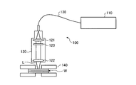
- FIG. 1 is a schematic diagram illustrating a schematic configuration of the laser welding apparatus according to the first embodiment.
- FIG. 2 is a schematic diagram illustrating a diffractive optical element.
- FIG. 3 is a schematic diagram illustrating a plurality of beams.
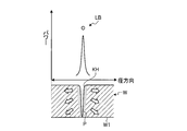
- FIG. 4A is a schematic diagram illustrating a state of a laser beam and a corresponding molten state of a processing target.
- FIG. 4B is a schematic diagram illustrating a state of a laser beam and a corresponding molten state of a processing target.
- FIG. 4C is a schematic diagram illustrating the state of the laser beam and the corresponding molten state of the processing target.
- FIG. 4D is a schematic diagram illustrating the state of the laser beam and the corresponding molten state of the processing target.
- FIG. 4A is a schematic diagram illustrating a state of a laser beam and a corresponding molten state of a processing target.
- FIG. 4B is a schematic diagram illustrating a state of
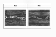
- FIG. 5 is a diagram showing photographs of the front surface and the back surface of the lap welded copper foil of Example 1.
- FIG. 6 is a diagram showing a photograph of the cross section of FIG.
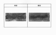
- FIG. 7 is a diagram showing photographs of the front and back surfaces of the lap welded copper foil of Example 2.
- FIG. 8 is a partially enlarged view of FIG.
- FIG. 9 is a diagram showing a photograph of the cross section of FIG.
- FIG. 10A is a schematic diagram illustrating an example in which a diffractive optical element divides a laser beam into a plurality of beams.
- FIG. 10B is a schematic diagram illustrating an example in which a diffractive optical element divides a laser beam into a plurality of beams.
- FIG. 10A is a schematic diagram illustrating an example in which a diffractive optical element divides a laser beam into a plurality of beams.
- FIG. 10B is a schematic diagram illustrating an example in which a diffractive optical element divides a
- FIG. 10C is a schematic diagram illustrating an example in which a diffractive optical element divides a laser beam into a plurality of beams.
- FIG. 10D is a schematic diagram illustrating an example in which a diffractive optical element divides a laser beam into a plurality of beams.
- FIG. 10E is a schematic diagram illustrating an example in which a diffractive optical element divides a laser beam into a plurality of beams.
- FIG. 10F is a schematic diagram illustrating an example in which a diffractive optical element divides a laser beam into a plurality of beams.
- FIG. 10G is a schematic diagram illustrating an example in which a diffractive optical element divides a laser beam into a plurality of beams.
- FIG. 10H is a schematic diagram illustrating an example in which a diffractive optical element divides a laser beam into a plurality of beams.
- FIG. 11 is a schematic diagram illustrating a schematic configuration of the laser welding apparatus according to the second embodiment.
- FIG. 12 is a schematic diagram illustrating a schematic configuration of the laser welding apparatus according to the third embodiment.
- FIG. 13 is a schematic diagram illustrating a schematic configuration of a laser welding apparatus according to the fourth embodiment.
- FIG. 14 is a schematic diagram illustrating a schematic configuration of a laser welding apparatus according to the fifth embodiment.
- FIG. 15 is a schematic diagram illustrating a schematic configuration of a laser welding apparatus according to the sixth embodiment.
- FIG. 16A is a diagram illustrating a configuration example of an optical fiber.
- FIG. 16B is a diagram illustrating a configuration example of an optical fiber.
- FIG. 1 is a schematic diagram illustrating a schematic configuration of the laser welding apparatus according to the first embodiment.
- the laser welding device 100 includes a laser device 110, an optical head 120, an optical fiber 130 connecting the laser device 110 and the optical head 120, and a fixing device 140.
- the processing target W is configured by laminating a plurality of metal foils.
- the thickness of each metal foil is, for example, 2 ⁇ m to 20 ⁇ m, but is not particularly limited.
- the number of metal foils is, for example, 10 to 100, but is not particularly limited.
- the metal foil includes copper and aluminum, but the material of the metal foil is not particularly limited.
- the laser device 110 is configured to output a laser beam having a power of several kW, for example.
- the laser device 110 may include a plurality of semiconductor laser elements therein, and may be configured to output a multi-mode laser beam having a power of several kW as a total output of the plurality of semiconductor laser elements.
- the laser device 110 may include various laser light sources such as a fiber laser, a YAG laser, and a disk laser.
- the optical fiber 130 guides the laser light output from the laser device 110 and inputs the laser light to the optical head 120.
- the fixing device 140 is a device that fixes the processing target W by sandwiching it from the front side and the back side.
- the surface side is the side of the main surface to which the laser light is irradiated.
- the fixing device 140 is provided with an opening such as a hole or a groove so that a portion to be irradiated with laser light in a processing target and its periphery are exposed. It is preferable that the fixing device 140 can fix the processing target W such that the gap between the metal foils is as small as possible.
- the optical head 120 is an optical device for irradiating the laser light input from the laser device 110 toward the processing target W.
- the optical head 120 includes a collimator lens 121 and a condenser lens 122.
- the collimator lens 121 is an optical system for converting the input laser light into parallel light.
- the condensing lens 122 is an optical system for condensing the parallelized laser light and irradiating the laser light L to the processing target W.
- the optical head 120 is configured to be able to change the relative position with respect to the processing target W in order to sweep the laser light L while irradiating the processing target W with the laser light L.
- the method of changing the relative position with respect to the processing target W includes moving the optical head 120 itself, moving the processing target W, and the like. That is, the optical head 120 may be configured to be able to sweep the laser light L with respect to the fixed processing target W.
- the irradiation position of the laser light L from the optical head 120 may be fixed, and the processing target W may be held movably with respect to the fixed laser light L.
- the optical head 120 includes a diffractive optical element 123 as an example of a beam shaper disposed between the collimator lens 121 and the condenser lens 122.
- the diffractive optical element 123 here includes a plurality of diffraction gratings 123a having different periods integrally formed.
- the diffractive optical element 123 can shape the beam shape by bending or overlapping the input laser light in a direction affected by each diffraction grating.
- the diffractive optical element 123 is disposed between the collimator lens 121 and the condenser lens 122.
- the diffractive optical element 123 is disposed on the optical fiber 130 side from the collimator lens 121 and on the processing target W side from the condenser lens 122. Is also good.
- the diffractive optical element 123 divides the laser light input from the collimator lens 121 into a plurality of beams. Specifically, the diffractive optical element 123 disperses the position of the optical head 120 with respect to the surface of the processing target W such that the centers of the plurality of beams do not overlap within a predetermined region on the surface. The laser beam is divided so that a plurality of beams can be irradiated.
- FIG. 3 is a schematic diagram illustrating a plurality of beams.
- the laser light L includes a plurality of beams B split by the diffractive optical element 123.
- the diameter of the circle representing the beam B is the beam diameter.
- the circular area A is a predetermined area on the surface of the processing target W, and a plurality (16 in this embodiment) of the beams B are dispersed in the area A so that their centers do not overlap each other. Is applied to the region A of the processing target W.
- the beam B is arranged in a ring shape having a diameter D in the region A.
- the region A has a shape corresponding to the shape of the outer contour of the arrangement of the beam B.
- Each beam B has a Gaussian power distribution in the radial direction of the beam cross section.
- the power distribution of the beam B is not limited to the Gaussian shape.
- the Gaussian shape in this specification is not limited to a shape that is exactly a Gaussian shape, but also includes a shape that can be approximated by a Gaussian shape.
- the beam diameter of the beam B is defined as a diameter of a region including a peak and having an intensity of 1 / e 2 or more of the peak intensity.
- the length of a region perpendicular to the sweep direction and having an intensity of 1 / e 2 or more of the peak intensity is defined as the beam diameter.
- the processing target W When performing welding using the laser welding apparatus 100, first, the processing target W is arranged in an area irradiated with the laser beam L. Subsequently, while irradiating the processing target W with the laser light L including the plurality of beams B split by the diffractive optical element 123, the laser light L and the processing target W are relatively moved to sweep the laser light L. While welding, the processing target W in the portion irradiated with the laser light L is melted and welded.
- the power distribution of the laser beam LA for welding is a Gaussian distribution, but the peak power is low and the power density at the peak is low.
- Such laser light LA can be realized, for example, by irradiating the processing target W with the laser light in a defocused state. Defocusing is to shift the focusing position of the laser beam by the focusing lens of the optical head from the surface position of the processing target W. In this case, when the surface of the processing target W is irradiated with the laser beam LA, a molten pool P is formed on the processing target W, but no keyhole is formed.
- the molten pool P may not spread so much and the welding process may not proceed.
- the defocus state is adjusted so that the peak power is increased in order to appropriately expand the molten pool P, poor welding is likely to occur.
- the energy supplied by the laser beam LA the energy that does not contribute to welding increases, which is inefficient. Therefore, it is difficult to suitably perform welding even when the laser light having a Gaussian distribution is in a defocused state.
- the laser beam L is as shown in FIG. 4B, even if each beam has a single-peak power distribution such as a Gaussian distribution, their peak powers are relatively low. As a result, so-called heat conduction type welding in which no keyhole is formed can be realized. Moreover, the individual beams have a higher power density than in the case of FIG. 4A. Therefore, the molten pool P spreads more than in the case of FIG. 4A, and it is relatively easy to reach the back surface W1 of the processing target W.
- the back surface W1 is a surface on the opposite side to the surface on which the laser light L is irradiated. As a result, higher quality lap welding can be realized for the processing target W.
- a keyhole may be formed by each beam.
- the laser beam L is set so that the keyhole is made shallow and dispersed at a plurality of locations. If so, heat conduction type welding is dominant as a result.
- FIG. 4D shows a case where a laser beam LC having a shape having a beam at the center of a circle formed by the beam of the laser beam L is used.
- a molten pool P and a keyhole KH are formed in the processing target W.
- a keyhole KH of an appropriate size is formed by the center beam to secure the depth (penetration depth) of the molten pool P and the periphery thereof. May be used to melt the metal foil of the processing target W. Thereby, welding without breaking of the metal foil can be realized.
- each of the beams B is processed. It is preferable to set so that each metal foil constituting the target W has a power density that does not open a hole. Then, it is preferable to set the power density of the beam B and irradiate the irradiation position in a dispersed manner so as to form a molten pool penetrating the processing target W to the back surface W1 by the beam B. However, it is preferable to set the power density and the irradiation position of the beam B so that the molten metal does not drop from the back surface W1 side.
- the characteristics of the processing target W (the material and thickness of the metal foil, the number of superimpositions, and the like), the number of the beams B, the peak power, and the arrangement of the irradiation positions are set. It is preferable to set the shape. By setting at least one of these items, higher-quality lap welding can be realized, but by appropriately combining and setting two or more, higher-quality lap welding can be achieved. , And can be stably realized without variation.
- Example 1 An object to be processed was formed by laminating 20 copper foils each having a thickness of 8 ⁇ m, and a laser beam was irradiated to this to perform laser welding.
- Laser light output from the laser device has a Gaussian distribution, and its wavelength is 1070 nm.
- the power of the laser beam was 600 W, 700 W, or 800 W.
- this laser beam was divided into 16 beams arranged in a ring shape with a diameter of 466 ⁇ m as shown in FIG.
- the sweep speed of the laser beam with respect to the processing target was 3 mm / s, 5 mm / s, or 10 mm / s.
- FIG. 5 is a diagram showing photographs of the front and back surfaces of the lap welded copper foil of Example 1.
- FIG. 6 is a diagram showing a photograph of the cross section of FIG. 5 and 6 show the case where the power of the laser beam is 700 W and the sweep speed is 5 mm / s. As shown in FIGS. 5 and 6, high-quality lap welding without holes or tears on the front and back surfaces was realized.
- Example 2 An object to be processed was formed by laminating 50 pieces of copper foil having a thickness of 8 ⁇ m, and laser irradiation was performed on the object to perform laser welding.
- Laser light output from the laser device has a Gaussian distribution, and its wavelength is 1070 nm.
- the power of the laser light was 1000 W.
- the laser light is divided by the diffractive optical element into 16 beams arranged in a ring shape having a diameter of 466 ⁇ m as shown in FIG. Irradiated.
- the ratio of the power of the center beam to the total power of the 16 ring-shaped beams was 5: 5.
- the sweep speed of the laser beam with respect to the processing target was 5 mm / s.
- FIG. 7 is a view showing photographs of the front and back surfaces of the lap welded copper foil of Example 2.
- FIG. 8 is a partially enlarged view of FIG. 7 and shows a weld bead in an enlarged manner.
- FIG. 9 is a diagram showing a photograph of the cross section of FIG. As shown in FIGS. 7, 8, and 9, high-quality lap welding without holes or tears on the front and back surfaces was realized.
- high-quality lap welding could be realized under the conditions where the power of the laser beam and the sweep speed were appropriately combined.
- the power of the laser beam is increased when the sweep speed is increased, and the power of the laser beam is decreased when the sweep speed is decreased. It has been confirmed that it is preferable to set the energy of the laser light to be applied to the target within an appropriate range.
- the manner of dividing the laser beam is not limited to that shown in FIG. 10A to 10H are schematic diagrams illustrating an example in which the diffractive optical element 123 divides a laser beam into a plurality of beams. It is assumed that the sweep direction SD faces upward in the drawing.
- the laser beam L1 applied to the processing target W includes 17 beams B1 each having a Gaussian shape.
- the circular area A1 which is a predetermined area on the surface of the processing target W, 16 beams B1 are arranged in a ring shape, and one beam B1 is arranged in the center of the ring and is irradiated on the area A1.
- the ratio of the power of the center beam B1 to the total power of the 16 ring-shaped beams B1 is, for example, 1: 9.
- the laser light L2 applied to the processing target W includes nine beams B2 each having a Gaussian shape, and has a rectangular shape as a predetermined region on the surface of the processing target W. Within the area A2, the area A2 is irradiated in a rectangular shape.
- the laser beam L3 applied to the processing target W includes six beams B3 each having a Gaussian shape, and has a triangular shape that is a predetermined region on the surface of the processing target W. In the area A3, the light is radiated to the area A3 while being arranged in a triangular shape.
- the laser beam L4 applied to the processing target W includes 21 beams B4 each having a Gaussian shape.
- the circular area A4 which is a predetermined area on the surface of the processing target W
- 12 of these beams B4 are arranged in a first ring shape at the outermost circumference, and 8 beams are formed in the first ring shape.
- the second ring is arranged on the peripheral side, and one of them is arranged at the center of the ring to irradiate the area A4.
- the laser beam L5 applied to the processing target W includes 13 beams B5 each having a Gaussian shape.
- the circular area A5 which is a predetermined area on the surface of the processing target W
- eight of these beams B5 are arranged in the outermost periphery in a first ring shape, and four are in the first ring shape.
- the second ring is arranged on the peripheral side, and one of them is arranged at the center of the ring to irradiate the area A5.
- the first ring-shaped beam B5 and the second ring-shaped beam B5 overlap.
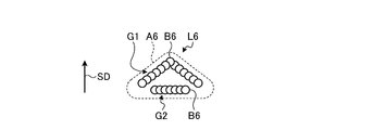
- the laser beam L6 applied to the processing target W includes 20 beams B6 each having a Gaussian shape.
- Each beam B6 is included in one of the beam groups G1 and G2.
- the beam group G1 has a mountain shape whose apex is directed in the sweep direction SD, and the beam group G2 is located behind the beam group G1 and forms a straight line.
- the beam groups G1 and G2 are arranged in a triangular area A6, which is a predetermined area on the surface of the processing target W, and are irradiated on the area A6.
- the laser beam L7 applied to the processing target W includes 13 beams B7 each having a Gaussian shape.
- the beam B7 has the same mountain shape as the beam group G1 in FIG.
- the beam B7 is arranged in a triangular area A7, which is a predetermined area on the surface of the processing target W, and is irradiated on the area A7.
- the laser beam L8 includes 17 beams B8.
- the 16 beams B8 are positioned so as to form a substantially ring shape or a substantially octagonal shape with one beam B8 as a center.
- the 17 beams B8 are arranged so as to fill the rectangular grid when the matrix M is defined.
- the beams may be arranged to fill the grid or may be arranged more freely.
- the predetermined area has a shape corresponding to the outer contour of the shape formed by the dispersed beams.
- FIGS. 10A to 10H can be realized by appropriately designing the characteristics of the diffraction grating constituting the diffractive optical element 123.
- a first object to be processed was formed by laminating 20 pieces of 8 ⁇ m thick copper foil.
- a second processing target was configured by laminating 50 copper foils each having a thickness of 8 ⁇ m. These were irradiated with laser light to perform laser welding.
- Laser light output from the laser device has a Gaussian distribution, and its wavelength is 1070 nm.
- the power of the laser beam was set to 600 W, 700 W, or 800 W for the first processing target, and set to 1000 W, 1300 W, or 1500 W for the second processing target.
- this laser light is divided by a diffractive optical element into 16 beams arranged in a ring shape with a diameter of 600 ⁇ m as shown in FIG. Irradiated.
- the ratio between the power of the center beam and the sum of the powers of the 16 ring-shaped beams was 1: 9 for the first processing object and 5: 5 for the second processing object.
- the sweep speed of the laser beam for the processing target is 3 mm / s, 5 mm / s, or 10 mm / s for the first processing target, and 3 mm / s, 5 mm / s, 10 mm / s for the second processing target.
- the welding length 1 was 10 mm.
- Table 1 shows the relationship between welding energy and welding energy per unit thickness (mm) and unit thickness ( ⁇ m) in other examples.
- the symbol “A” indicates that the welding condition is good over the entire length of the welding length
- the symbol “B” indicates that the welding condition is good over ⁇ or more of the welding length
- “C” indicates that the welding state is good over 2 of the welding length.
- the input energy per unit welding length (mm) and unit thickness ( ⁇ m) is 0.02 (J / ( ⁇ m * mm)) or more and 1.67 (J / ( ⁇ m * mm)).
- the following was preferable, and it was confirmed that 0.04 (J / ( ⁇ m * mm)) or more and 1.46 or less (J / ( ⁇ m * mm)) were more preferable.
- FIG. 11 is a diagram illustrating a schematic configuration of a laser welding apparatus according to the second embodiment.
- the laser welding device 200 irradiates the processing target W with the laser beam L to perform welding on the processing target W.
- the laser welding device 200 realizes welding by the same operation principle as the laser welding device 100. Therefore, only the device configuration of the laser welding device 200 will be described below.
- the laser welding device 200 includes a laser device 210, an optical head 220, an optical fiber 230, and a fixing device 240.
- the laser device 210 has the same configuration as the laser device 110, and is configured to output, for example, a laser beam having a power of several kW.
- the optical fiber 230 guides the laser light output from the laser device 210 and inputs the laser light to the optical head 220.
- the fixing device 240 fixes the processing target W.
- the optical head 220 is an optical device for irradiating a laser beam input from the laser device 210 toward the processing target W, like the optical head 120.
- the optical head 220 includes a collimator lens 221 and a condenser lens 222.
- the optical head 220 has a galvano scanner arranged between the condenser lens 222 and the processing target W.
- the galvano scanner is a device that can control the angle of the two mirrors 224a and 224b to move the irradiation position of the laser beam L without moving the optical head 220 and sweep the laser beam L. is there.
- the laser welding apparatus 200 includes a mirror 226 for guiding the laser light L emitted from the condenser lens 222 to a galvano scanner.
- the angles of the mirrors 224a and 224b of the galvano scanner are changed by motors 225a and 225b, respectively.
- the motors 225a and 225b are driven by a driver (not shown).
- the optical head 220 includes a diffractive optical element 223 as a beam shaper, disposed between the collimator lens 221 and the condenser lens 222. Like the diffractive optical element 123, the diffractive optical element 223 splits the laser beam input from the collimator lens 221 into a plurality of beams having the same peak power. Specifically, the diffractive optical element 223 causes the optical head 220 to disperse the position of the surface of the processing target W such that the centers of the plurality of beams do not overlap within a predetermined region on the surface. The laser beam is divided so that a plurality of beams can be irradiated.
- the diffractive optical element 223 is designed to split the laser beam into a plurality of beams as shown in, for example, FIG. 3 and FIGS. 10A to 10G. Thereby, the laser welding apparatus 200 can perform the overlap welding of the processing target W with higher quality.
- the diffractive optical element 223 is disposed between the collimating lens 221 and the condenser lens 222 as in the first embodiment, the diffractive optical element 223 is located closer to the optical fiber 230 than the collimating lens 221 and closer to the processing target W than the condenser lens 222. May be installed.
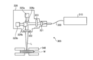
- FIG. 12 is a schematic diagram illustrating a schematic configuration of the laser welding apparatus according to the third embodiment.
- the laser welding apparatus 300 irradiates the processing target W with the laser beam L to perform welding on the processing target W.
- the laser welding device 300 realizes welding by the same operation principle as the laser welding devices 100 and 200.
- the components other than the optical head 320 (the laser device 310, the optical fiber 330, and the fixing device 340) have the same configurations as the corresponding components of the laser welding devices 100 and 200. Therefore, only the device configuration of the optical head 320 will be described below.
- the optical head 320 is an optical device for irradiating the laser light input from the laser device 310 toward the processing target W, similarly to the optical heads 120 and 220.
- the optical head 320 includes a collimator lens 321 and a condenser lens 322.
- the optical head 320 has a galvano scanner disposed between the collimator lens 321 and the condenser lens 322.
- the angles of the mirrors 324a and 324b of the galvano scanner are changed by motors 325a and 325b, respectively.
- the motors 325a and 325b are driven by a driver (not shown).
- a galvano scanner is provided at a position different from that of the optical head 220.
- the irradiation position of the laser light L is moved and the laser light L is swept without moving the optical head 320. Can be.
- the optical head 320 includes a diffractive optical element 323 as a beam shaper disposed between the collimator lens 321 and the condenser lens 322.
- the diffractive optical element 323 divides the laser beam input from the collimator lens 321 into a plurality of beams having the same peak power. Specifically, the diffractive optical element 323 disperses the position of the optical head 320 so that the center of the plurality of beams does not overlap the surface of the processing target W within a predetermined area on the surface. The laser beam is divided so that a plurality of beams can be irradiated.
- the diffractive optical element 323 is designed to split the laser beam into a plurality of beams as shown in, for example, FIG. 3 and FIGS. 10A to 10G. Accordingly, the laser welding apparatus 300 can perform the overlap welding of the processing target W with higher quality.
- the diffractive optical element 323 is disposed between the collimating lens 321 and the condenser lens 322 as in the first embodiment, the diffractive optical element 323 is located closer to the optical fiber 330 than the collimator lens 321 and closer to the processing target W than the condenser lens 322. May be installed.
- FIG. 13 is a diagram illustrating a schematic configuration of a laser welding apparatus according to the fourth embodiment.
- the laser welding device 400 irradiates a laser beam to the processing target W to perform welding on the processing target W.
- the laser welding apparatus 400 realizes a welding method by the same operation principle as the laser welding apparatus 100. Therefore, only the device configuration of the laser welding device 400 will be described below.
- the laser welding apparatus 400 includes a plurality of laser devices that output laser light, an optical head 420 that irradiates the laser light to the processing target W, and a plurality of optical fibers that guide the laser light output from the laser device to the optical head 420. It has. In the drawing, two laser devices 411 and 412 are shown among a plurality of laser devices, and optical fibers 431 and 432 are shown among a plurality of optical fibers.
- the laser device 411 has the same configuration as the laser device 110, and is configured to output, for example, a multi-mode laser beam L11 having an output of several kW.
- the laser device 412 has the same configuration as the laser device 110, and has an output of, for example, several kW, and is configured to output a laser beam L12, which is a plurality of multi-mode laser beams. Other laser devices are configured similarly to the laser device 110.
- the optical fibers 431 and 432 guide the laser beams L11 and L12 to the optical head 420, respectively.
- the plurality of optical fibers may be replaced with a multi-core fiber.
- the optical head 420 is an optical device for irradiating a laser beam such as laser beams L11 and L12 guided from a plurality of laser devices including the laser devices 411 and 412 toward the processing target W.
- the optical head 420 includes a collimator lens 421a and a condenser lens 422a for the laser beam L11, a collimator lens 421b and a condenser lens 422b for the laser beam L12, and a collimator lens and a condenser lens for other laser beams.
- Collimating lenses such as the collimating lenses 421a and 421b are optical systems for temporarily collimating the laser light guided by the optical fibers 431 and 432, respectively.
- the collimating lens and the condensing lens may each be constituted by a plurality of lenses for collimating or condensing a plurality of laser beams.
- the optical head 420 irradiates the processing target W with a plurality of laser beams including the laser beams L11 and L12. That is, the laser light irradiated toward the processing target W is constituted by a plurality of beams. It is preferable that each of the beams is set so as to have a power density that does not open a hole in each metal foil constituting the processing target W. It is preferable to set the power density of the beam and irradiate the irradiation position in a dispersed manner so as to form a molten pool penetrating the processing target W to the back surface by the beam. However, it is preferable to set the beam power density, the irradiation position, and the like so that the molten metal does not drop from the back side of the processing target.
- the arrangements illustrated in FIGS. 3, 10A to 10H can be realized. Note that the number of beams may be appropriately increased or decreased.
- FIG. 12 is a diagram illustrating a schematic configuration of a laser welding apparatus according to the fifth embodiment.
- the laser welding device 500 irradiates the processing target W with a laser beam to perform welding on the processing target W.
- the laser welding device 500 realizes a welding method by the same operation principle as the laser welding device 100. Therefore, only the device configuration of the laser welding device 500 will be described below.
- the laser welding device 500 includes a laser device 510 that outputs laser light, an optical head 520 that irradiates the laser light to the processing target W, and a plurality of optical fibers that guide the laser light output from the laser device 510 to the optical head 520. Have. In the drawing, among the plurality of optical fibers, optical fibers 531, 533 and 534 are shown.
- the laser device 510 has the same configuration as the laser device 110, and is configured to output, for example, a multi-mode laser beam having an output of several kW.
- the laser device 510 is used to output a plurality of laser lights that irradiate the processing target W. Therefore, in the optical fiber for guiding the laser light output from the laser device 510 to the optical head 520, a branch unit 532 is provided between the optical fiber 531 and the plurality of optical fibers including the optical fibers 533 and 534. I have.
- the laser device 510 is configured to split the laser light output from the laser device 510 into a plurality of laser lights and then guide the laser light to the optical head 520.
- the plurality of optical fibers including the optical fibers 531 and 533 guide the laser light to the optical head 520, respectively.
- the plurality of optical fibers may be replaced with a multi-core fiber.
- the optical head 520 is an optical device for irradiating the processing target W with a plurality of laser beams including the laser beams L11 and L12, which are branched by the branch unit 532 and guided by the plurality of optical fibers including the optical fibers 531 and 533. It is. Therefore, the optical head 520 includes a collimating lens 521a and a condenser lens 522a for the laser beam L11, a collimating lens 521b and a condenser lens 522b for the laser beam L12, and a collimating lens for other laser beams. And a condenser lens. The collimating lenses 521a, 521b, etc.
- the collimating lens and the condensing lens may each be constituted by a plurality of lenses for collimating or condensing a plurality of laser beams.
- the optical head 520 irradiates a plurality of laser beam processing targets W including the laser beams L11 and L12. That is, the laser light irradiated toward the processing target W is constituted by a plurality of beams. It is preferable to set the power density of the beam and irradiate the irradiation position in a dispersed manner so as to form a molten pool penetrating the processing target W to the back surface by the beam. However, it is preferable to set the beam power density, the irradiation position, and the like so that the molten metal does not drop from the back side of the processing target.
- the arrangements illustrated in FIGS. 3, 10A to 10H can be realized.
- the number of beams may be appropriately increased or decreased.
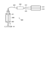
- FIG. 15 is a diagram illustrating a schematic configuration of a laser welding apparatus according to the sixth embodiment.
- the laser welding apparatus 600 irradiates the processing target W with the laser beam L to perform welding on the processing target W.
- the laser welding apparatus 600 realizes a welding method based on the same operation principle as the laser welding apparatus 100. Therefore, hereinafter, only the configuration of the laser welding apparatus 600 will be described.
- the laser welding device 600 includes a plurality of laser devices that output laser light, an optical head 620 that irradiates the laser light to the processing target W, and a plurality of lights that guide the laser light output from the plurality of laser devices to the optical head 620. With fiber.
- the laser devices 611 and 612 are shown, and among the plurality of optical fibers, the optical fibers 631, 632 and 635 are shown.
- the laser device 611 has the same configuration as the laser device 110, and is configured to output, for example, a multi-mode laser beam having an output of several kW.
- the laser device 612 has the same configuration as the laser device 110, for example, has an output of several kW, and is configured to output a plurality of multi-mode laser beams. Other laser devices are configured similarly to the laser device 110.
- laser beams output from a plurality of laser apparatuses including the laser apparatuses 611 and 612 are combined before being guided to the optical head 620.
- a coupling portion 634 is provided between the optical fiber 635 and a plurality of optical fibers including the optical fibers 631 and 632 for guiding the laser beams output from the plurality of laser devices including the laser devices 611 and 612 to the optical head 620.
- Laser beams output from a plurality of laser devices including the laser devices 611 and 612 are guided in parallel in the optical fiber 635.
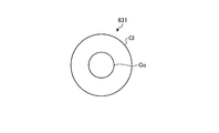
- the optical fiber 631 (and 632) is a normal optical fiber. That is, the optical fiber 631 (and 632) is an optical fiber in which a clad Cl having a lower refractive index than the core region Co is formed around one core region Co. Note that the other optical fibers provided between the laser unit 611 and the laser unit 612 other than the laser unit 634 and the coupling unit 634 are also ordinary optical fibers like the optical fiber 631.
- the optical fiber 635 is a multi-core fiber.
- the optical fiber 635 has a plurality of core regions, and a clad Cl having a lower refractive index than the core region is formed around the plurality of core regions.
- a clad Cl having a lower refractive index than the core region is formed around the plurality of core regions.
- two core regions Co1 and Co2 are shown.
- the core region Co2 includes a plurality of core regions.
- the coupling section 634 the core region of the optical fiber connected to each of the plurality of laser devices and each of the core regions of the optical fiber 635 are coupled.
- Each of the laser beams output from the plurality of laser devices is guided by each of the plurality of core regions of the core region Co2.
- the optical head 620 is an optical device for irradiating the processing target W with the laser light L combined by the combining unit 634.
- the optical head 620 includes a plurality of collimating lenses including a collimating lens 621 therein and a plurality of focusing lenses including a focusing lens 622.
- the laser welding apparatus 600 has an optical head 620 that does not include a diffractive optical element and does not have an independent optical system for a plurality of laser lights, but the laser light output from each laser apparatus is It is combined before being guided to the optical head 620.
- the laser beam L irradiated toward the processing target W is constituted by a plurality of beams. It is preferable to set the power density of the beam and irradiate the irradiation position in a dispersed manner so as to form a molten pool penetrating the processing target W to the back surface by the beam. However, it is preferable to set the beam power density, the irradiation position, and the like so that the molten metal does not drop from the back side of the processing target.
- the arrangements illustrated in FIGS. 3, 10A to 10H can be realized. Note that the number of beams may be appropriately increased or decreased.
- the diffractive optical element divides the laser light into a plurality of beams having the same peak power.
- the peak powers of the multiple beams need not be equal. That is, it is only necessary that the metal foil does not include a beam having a peak protruding to such an extent that a hole or breakage is generated.
- the power distribution of each beam is not limited to the Gaussian shape, but may be another single-peak shape.
- the sweep may be performed by known wobbling or weaving.
- the object to be processed is composed of only a plurality of metal foils. However, a plurality of metal foils are superimposed, and a metal plate having a thickness of 100 ⁇ m or more is further superimposed thereon to constitute the object to be processed. May be.
- the metal plate contains, for example, copper or aluminum.
- the laser light used is not limited to the multi-mode, and a single-mode laser light may be used.
- the laser beam is composed of a plurality of beams, each of the plurality of beams is set so as to have a power density that does not open a hole in the metal foil, and the plurality of beams form a molten pool that penetrates a processing target. Setting the power densities of a plurality of beams so as to form them and irradiating the irradiation positions in a dispersed manner is also effective in the case of welding in which laser light is not swept onto a processing target, such as spot welding. It is.
- the present invention is not limited by the above embodiments.
- the present invention also includes a configuration obtained by appropriately combining the components of the above-described embodiments. Further, further effects and modifications can be easily derived by those skilled in the art. Therefore, the broader aspects of the present invention are not limited to the above-described embodiments, and various modifications are possible.
- the present invention is suitable for application to lap welding of metal foils.
Abstract
In this welding method, a workpiece in which a plurality of metal foils overlap each other is arranged in a region irradiated with laser light constituted by a plurality of beams, and the plurality of beams of the laser light are emitted onto the surface of the workpiece by distributing the positions to be irradiated with the beams in a predetermined region on the surface such that the centers of the beams do not overlap, whereby the irradiated portion of the workpiece is melted and welded. Each of the plurality of beams is set to have a power density insufficient to form a hole in the metal foils, while the power density of the plurality of beams are set so that a molten pool passing through the workpiece is formed by the plurality of beams. Moreover, the irradiation positions of the beams are distributed.
Description
本発明は、溶接方法および溶接装置に関する。
The present invention relates to a welding method and a welding device.
金属材料からなる加工対象を溶接する手法の一つとして、レーザ溶接が知られている。レーザ溶接とは、レーザ光を加工対象の溶接部分に照射し、レーザ光のエネルギーで溶接部分を溶融させる溶接方法である。レーザ光が照射された溶接部分には、溶融池と呼ばれる溶融した金属材料の液溜りが形成され、その後、溶融池が固化することによって溶接が行われる。
レ ー ザ Laser welding is known as one of the techniques for welding a workpiece made of a metal material. Laser welding is a welding method in which a laser beam is applied to a welding portion to be processed and the welding portion is melted by the energy of the laser beam. A liquid pool of a molten metal material called a molten pool is formed in the welded portion irradiated with the laser beam, and thereafter, the molten pool is solidified to perform welding.
一方、金属箔を重ね合わせて溶接したものは、様々な技術分野において使用されている。例えば、銅箔を重ね合わせて溶接したものは、リチウムイオン電池の電極として用いられている。金属箔の重ね合わせ溶接について、品質が安定した溶接技術が広く求められている。金属箔の重ね合わせ溶接に関する技術としては、例えば特許文献1に開示されているものがある。
On the other hand, those obtained by overlapping and welding metal foils are used in various technical fields. For example, a copper foil that has been overlapped and welded is used as an electrode of a lithium ion battery. For lap welding of metal foils, welding technology with stable quality is widely demanded. As a technique relating to lap welding of metal foil, for example, there is a technique disclosed in Patent Document 1.
レーザ溶接を用いて金属箔を重ね合わせ溶接する場合は、金属箔はきわめて薄いため、レーザ光のパワー密度が高すぎると金属箔に孔や破れ等が発生し、許容程度以上のダメージを与える場合がある。一方、レーザ光のパワー密度が低すぎると、重ね合わせた金属箔の最下層までレーザ光のエネルギーが届かず、溶接プロセスが進まない場合がある。これらの現象は、溶接を品質の低下させる原因となる。
When the metal foil is overlapped and welded using laser welding, the metal foil is extremely thin, so if the power density of the laser beam is too high, holes or tears will occur in the metal foil, causing more than acceptable damage. There is. On the other hand, if the power density of the laser beam is too low, the energy of the laser beam may not reach the lowermost layer of the superposed metal foil, and the welding process may not proceed. These phenomena cause the quality of the weld to deteriorate.
本発明は、上記に鑑みてなされたものであって、その目的は、より品質の高い重ね合わせ溶接を実現することができる溶接方法および溶接装置を提供することにある。
The present invention has been made in view of the above, and an object of the present invention is to provide a welding method and a welding apparatus capable of realizing higher quality lap welding.
上述した課題を解決し、目的を達成するために、本発明の一態様に係る溶接方法は、複数の金属箔を重ね合わせた加工対象を、複数のビームによって構成されるレーザ光が照射される領域に配置し、前記レーザ光の複数のビームを、前記加工対象の表面に対して、前記表面上の所定の領域内で前記複数のビームの互いの中心が重ならないように位置を分散させて、前記複数のビームを照射し、照射された部分の前記加工対象を溶融して溶接を行い、前記複数のビームのそれぞれを、前記金属箔に孔が開かないパワー密度を有するように設定し、かつ、前記複数のビームによって、前記加工対象を貫通する溶融池を形成するように、前記複数のビームのパワー密度を設定するとともに照射位置を分散させて照射する。
In order to solve the above-described problem and achieve the object, in a welding method according to one embodiment of the present invention, a processing target in which a plurality of metal foils are overlapped is irradiated with a laser beam including a plurality of beams. Arranged in a region, a plurality of beams of the laser light, with respect to the surface of the processing target, dispersing the position such that the centers of the plurality of beams do not overlap within a predetermined region on the surface Irradiating the plurality of beams, performing welding by melting the processing target of the irradiated portion, each of the plurality of beams is set to have a power density that does not open a hole in the metal foil, Further, irradiation is performed by setting the power densities of the plurality of beams and dispersing the irradiation positions so that the plurality of beams form a molten pool penetrating the object to be processed.
本発明の一態様に係る溶接方法は、前記加工対象の特性に応じて、前記複数のビームの数、ピークパワー、および照射位置の配置、ならびに前記所定の領域の形状の少なくとも一つを設定する。
In the welding method according to one aspect of the present invention, at least one of the number of the plurality of beams, the peak power, the arrangement of the irradiation positions, and the shape of the predetermined region is set according to the characteristics of the processing target. .
本発明の一態様に係る溶接方法は、前記レーザ光を前記加工対象に向かって照射しながら前記レーザ光と前記加工対象とを相対的に移動させ、前記レーザ光を前記加工対象上で掃引する。
In the welding method according to one aspect of the present invention, the laser light and the processing target are relatively moved while irradiating the laser light toward the processing target, and the laser light is swept over the processing target. .
本発明の一態様に係る溶接方法は、前記金属箔が銅を含む。
溶 接 In the welding method according to one aspect of the present invention, the metal foil includes copper.
本発明の一態様に係る溶接方法は、レーザ光を複数のビームに分割可能であるビームシェイパによって、前記加工対象に照射する前記複数のビームを生成する。
溶 接 In the welding method according to one embodiment of the present invention, the plurality of beams that irradiate the object to be processed are generated by a beam shaper capable of dividing laser light into a plurality of beams.
本発明の一態様に係る溶接方法は、前記ビームシェイパが回折光学素子である。
In the welding method according to one aspect of the present invention, the beam shaper is a diffractive optical element.
本発明の一態様に係る溶接方法は、前記加工対象の単位厚さ(μm)、単位溶接長(mm)当たりの前記加工対象に照射される前記レーザ光のエネルギー(J/(μm*mm))が、0.02以上1.67以下である。
In the welding method according to one aspect of the present invention, the energy (J / (μm * mm) of the laser beam applied to the processing target per unit thickness (μm) and unit welding length (mm) of the processing target is provided. ) Is 0.02 or more and 1.67 or less.
本発明の一態様に係る溶接方法は、前記加工対象の単位厚さ(μm)、単位溶接長(mm)当たりの前記加工対象に照射される前記レーザ光のエネルギー(J/(μm*mm))が、0.04以上1.46以下である。
In the welding method according to one aspect of the present invention, the energy (J / (μm * mm) of the laser beam applied to the processing target per unit thickness (μm) and unit welding length (mm) of the processing target is provided. ) Is 0.04 or more and 1.46 or less.
本発明の一態様に係る溶接装置は、レーザ装置と、前記レーザ装置から出力されたレーザ光を、加工対象に向かって照射し、照射された部分の前記加工対象を溶融して溶接を行う光学ヘッドと、を備え、前記加工対象は、複数の金属箔を重ね合わせて構成され、前記加工対象に照射されるレーザ光は、複数のビームによって構成され、前記加工対象の表面に対して、前記表面上の所定の領域内で前記複数のビームの互いの中心が重ならないように位置を分散されて照射され、前記複数のビームのそれぞれを、前記金属箔に孔が開かないパワー密度を有するように設定し、かつ、前記複数のビームによって、前記加工対象を貫通する溶融池を形成するように、前記複数のビームのパワー密度を設定するとともに照射位置を分散させて照射する。
A welding device according to one embodiment of the present invention includes a laser device, and an optical device that irradiates a laser beam output from the laser device toward a processing target, melts the irradiated portion of the processing target, and performs welding. And a head, wherein the object to be processed is configured by stacking a plurality of metal foils, and a laser beam applied to the object to be processed is configured by a plurality of beams, and the surface of the object to be processed is The plurality of beams are irradiated in a predetermined area on the surface such that the centers of the plurality of beams do not overlap with each other, and each of the plurality of beams has a power density that does not cause a hole in the metal foil. And setting the power densities of the plurality of beams and irradiating the irradiation positions in a dispersed manner so as to form a molten pool penetrating the object to be processed by the plurality of beams.
本発明の一態様に係る溶接装置は、前記加工対象の特性に応じて、前記複数のビームの数、ピークパワー、および照射位置の配置、ならびに前記所定の領域の形状の少なくとも一つを設定する。
The welding device according to one aspect of the present invention sets at least one of the number of the plurality of beams, the peak power, the arrangement of the irradiation positions, and the shape of the predetermined region according to the characteristics of the processing target. .
本発明の一態様に係る溶接装置は、前記光学ヘッドは、前記複数のビームと前記加工対象とが相対的に移動可能なように構成され、前記複数のビームを前記加工対象上で掃引しつつ、前記溶融を行なって溶接を行う。
The welding apparatus according to one aspect of the present invention, wherein the optical head is configured such that the plurality of beams and the processing target are relatively movable, and sweeps the plurality of beams on the processing target. The welding is performed by performing the melting.
本発明の一態様に係る溶接装置は、前記金属箔が銅を含む。
溶 接 In the welding device according to one aspect of the present invention, the metal foil includes copper.
本発明の一態様に係る溶接装置は、レーザ光を複数のビームに分割可能であり、前記加工対象に照射する前記複数のビームを生成するビームシェイパをさらに備える。
溶 接 The welding apparatus according to one aspect of the present invention further includes a beam shaper capable of dividing the laser beam into a plurality of beams and generating the plurality of beams for irradiating the processing target.
本発明の一態様に係る溶接装置は、前記ビームシェイパが回折光学素子である。
溶 接 In the welding apparatus according to one aspect of the present invention, the beam shaper is a diffractive optical element.
本発明の一態様に係る溶接装置は、前記加工対象の単位厚さ(μm)、単位溶接長(mm)当たりの前記加工対象に照射される前記レーザ光のエネルギー(J/(μm*mm))が、0.02以上1.67以下である。
The welding apparatus according to one aspect of the present invention is configured such that the laser beam energy (J / (μm * mm)) applied to the processing target per unit thickness (μm) and unit welding length (mm) of the processing target ) Is 0.02 or more and 1.67 or less.
本発明の一態様に係る溶接装置は、前記加工対象の単位厚さ(μm)、単位溶接長(mm)当たりの前記加工対象に照射される前記レーザ光のエネルギー(J/(μm*mm))が、0.04以上1.46以下である。
The welding apparatus according to one aspect of the present invention is configured such that the laser beam energy (J / (μm * mm)) applied to the processing target per unit thickness (μm) and unit welding length (mm) of the processing target ) Is 0.04 or more and 1.46 or less.
本発明によれば、より品質の高い重ね合わせ溶接を実現することができるという効果を奏する。
According to the present invention, there is an effect that higher quality lap welding can be realized.
以下、添付図面を参照しながら、本発明の実施形態を詳細に説明する。なお、以下に説明する実施形態により本発明が限定されるものではない。また、図面の記載において、同一または対応する要素には適宜同一の符号を付している。
Hereinafter, embodiments of the present invention will be described in detail with reference to the accompanying drawings. The present invention is not limited by the embodiments described below. In the description of the drawings, the same or corresponding elements are denoted by the same reference numerals as appropriate.
(実施形態1)
図1は、実施形態1に係るレーザ溶接装置の概略構成を示す模式図である。レーザ溶接装置100は、レーザ装置110と、光学ヘッド120と、レーザ装置110と光学ヘッド120とを接続する光ファイバ130と、固定装置140とを備えている。加工対象Wは、金属箔を複数枚重ね合わせて構成されている。個々の金属箔の厚さは例えば2μm~20μmであるが特に限定はされない。また、金属箔の枚数は例えば10~100であるが特に限定はされない。金属箔は銅やアルミニウムを含むが、金属箔の材料は特に限定はされない。 (Embodiment 1)
FIG. 1 is a schematic diagram illustrating a schematic configuration of the laser welding apparatus according to the first embodiment. Thelaser welding device 100 includes a laser device 110, an optical head 120, an optical fiber 130 connecting the laser device 110 and the optical head 120, and a fixing device 140. The processing target W is configured by laminating a plurality of metal foils. The thickness of each metal foil is, for example, 2 μm to 20 μm, but is not particularly limited. The number of metal foils is, for example, 10 to 100, but is not particularly limited. The metal foil includes copper and aluminum, but the material of the metal foil is not particularly limited.
図1は、実施形態1に係るレーザ溶接装置の概略構成を示す模式図である。レーザ溶接装置100は、レーザ装置110と、光学ヘッド120と、レーザ装置110と光学ヘッド120とを接続する光ファイバ130と、固定装置140とを備えている。加工対象Wは、金属箔を複数枚重ね合わせて構成されている。個々の金属箔の厚さは例えば2μm~20μmであるが特に限定はされない。また、金属箔の枚数は例えば10~100であるが特に限定はされない。金属箔は銅やアルミニウムを含むが、金属箔の材料は特に限定はされない。 (Embodiment 1)
FIG. 1 is a schematic diagram illustrating a schematic configuration of the laser welding apparatus according to the first embodiment. The
レーザ装置110は、例えば数kWのパワーのレーザ光を出力できるように構成されている。例えば、レーザ装置110は、内部に複数の半導体レーザ素子を備え、当該複数の半導体レーザ素子の合計の出力として数kWのパワーのマルチモードのレーザ光を出力できるように構成することとしてもよい。また、レーザ装置110は、ファイバレーザ、YAGレーザ、ディスクレーザ等様々なレーザ光源を備えていてもよい。光ファイバ130は、レーザ装置110から出力されたレーザ光を導波し、光学ヘッド120に入力させる。固定装置140は、加工対象Wを表面側および裏面側から挟んで固定する装置である。ここで、表面側とはレーザ光が照射される主表面の側である。固定装置140は、加工対象においてレーザ光を照射する予定の箇所とその周囲が露出するように、孔や溝などの開口が設けられている。固定装置140は、金属箔の間にできるだけ隙間が無いように加工対象Wを固定できることが好ましい。
The laser device 110 is configured to output a laser beam having a power of several kW, for example. For example, the laser device 110 may include a plurality of semiconductor laser elements therein, and may be configured to output a multi-mode laser beam having a power of several kW as a total output of the plurality of semiconductor laser elements. Further, the laser device 110 may include various laser light sources such as a fiber laser, a YAG laser, and a disk laser. The optical fiber 130 guides the laser light output from the laser device 110 and inputs the laser light to the optical head 120. The fixing device 140 is a device that fixes the processing target W by sandwiching it from the front side and the back side. Here, the surface side is the side of the main surface to which the laser light is irradiated. The fixing device 140 is provided with an opening such as a hole or a groove so that a portion to be irradiated with laser light in a processing target and its periphery are exposed. It is preferable that the fixing device 140 can fix the processing target W such that the gap between the metal foils is as small as possible.
光学ヘッド120は、レーザ装置110から入力されたレーザ光を、加工対象Wに向かって照射するための光学装置である。光学ヘッド120は、コリメートレンズ121と集光レンズ122とを備えている。コリメートレンズ121は、入力されたレーザ光を平行光にするための光学系である。集光レンズ122は、平行光化されたレーザ光を集光し、レーザ光Lとして加工対象Wに照射するための光学系である。
The optical head 120 is an optical device for irradiating the laser light input from the laser device 110 toward the processing target W. The optical head 120 includes a collimator lens 121 and a condenser lens 122. The collimator lens 121 is an optical system for converting the input laser light into parallel light. The condensing lens 122 is an optical system for condensing the parallelized laser light and irradiating the laser light L to the processing target W.
光学ヘッド120は、加工対象W上でレーザ光Lの照射を行いながらレーザ光Lを掃引するために、加工対象Wとの相対位置を変更可能に構成されている。加工対象Wとの相対位置を変更する方法としては、光学ヘッド120自身を移動することや、加工対象Wを移動することなどが含まれる。すなわち、光学ヘッド120は、レーザ光Lを、固定されている加工対象Wに対して掃引可能に構成されてもよい。または、光学ヘッド120からのレーザ光Lの照射位置は固定され、加工対象Wが、固定されたレーザ光Lに対して移動可能に保持されてもよい。
The optical head 120 is configured to be able to change the relative position with respect to the processing target W in order to sweep the laser light L while irradiating the processing target W with the laser light L. The method of changing the relative position with respect to the processing target W includes moving the optical head 120 itself, moving the processing target W, and the like. That is, the optical head 120 may be configured to be able to sweep the laser light L with respect to the fixed processing target W. Alternatively, the irradiation position of the laser light L from the optical head 120 may be fixed, and the processing target W may be held movably with respect to the fixed laser light L.
光学ヘッド120は、コリメートレンズ121と集光レンズ122との間に配置された、ビームシェイパの一例としての回折光学素子123を備えている。ここでいう回折光学素子123は、図2に概念的に示すように、周期の異なる複数の回折格子123aを一体に構成したものである。回折光学素子123は、入力されたレーザ光を、各回折格子の影響を受けた方向に曲げたり、重ね合わせたりして、ビーム形状を成型することができる。本実施形態では回折光学素子123は、コリメートレンズ121と集光レンズ122の間に配置しているが、コリメートレンズ121より光ファイバ130側や、集光レンズ122より加工対象W側に設置してもよい。
The optical head 120 includes a diffractive optical element 123 as an example of a beam shaper disposed between the collimator lens 121 and the condenser lens 122. As shown conceptually in FIG. 2, the diffractive optical element 123 here includes a plurality of diffraction gratings 123a having different periods integrally formed. The diffractive optical element 123 can shape the beam shape by bending or overlapping the input laser light in a direction affected by each diffraction grating. In the present embodiment, the diffractive optical element 123 is disposed between the collimator lens 121 and the condenser lens 122. However, the diffractive optical element 123 is disposed on the optical fiber 130 side from the collimator lens 121 and on the processing target W side from the condenser lens 122. Is also good.
回折光学素子123は、コリメートレンズ121から入力されたレーザ光を複数のビームに分割する。具体的には、回折光学素子123は、光学ヘッド120が、加工対象Wの表面に対して、その表面上の所定の領域内で複数のビームの互いの中心が重ならないように位置を分散させて、複数のビームを照射可能な様に、レーザ光を分割する。
The diffractive optical element 123 divides the laser light input from the collimator lens 121 into a plurality of beams. Specifically, the diffractive optical element 123 disperses the position of the optical head 120 with respect to the surface of the processing target W such that the centers of the plurality of beams do not overlap within a predetermined region on the surface. The laser beam is divided so that a plurality of beams can be irradiated.
図3は、複数のビームを説明する模式図である。レーザ光Lは、回折光学素子123によって分割された複数のビームBを含んでいる。ビームBを表す円の直径がビーム径である。円形の領域Aは加工対象Wの表面上の所定の領域であり、複数(本実施形態では16)のビームBは、領域A内で、互いの中心が重ならないように位置が分散された状態で加工対象Wの領域Aに照射される。本実施形態1では、具体的にはビームBは領域A内で直径Dのリング状に配置される。領域AはビームBの配置の外輪郭の形状に相当する形状である。個々のビームBは、そのビーム断面の径方向においてガウシアン形状のパワー分布を有する。ただし、ビームBのパワー分布はガウシアン形状に限定されない。なお、本明細書におけるガウシアン形状とは、正確にガウシアン形状である形状に限られず、ガウシアン形状で近似できる形状も含む。
FIG. 3 is a schematic diagram illustrating a plurality of beams. The laser light L includes a plurality of beams B split by the diffractive optical element 123. The diameter of the circle representing the beam B is the beam diameter. The circular area A is a predetermined area on the surface of the processing target W, and a plurality (16 in this embodiment) of the beams B are dispersed in the area A so that their centers do not overlap each other. Is applied to the region A of the processing target W. In the first embodiment, specifically, the beam B is arranged in a ring shape having a diameter D in the region A. The region A has a shape corresponding to the shape of the outer contour of the arrangement of the beam B. Each beam B has a Gaussian power distribution in the radial direction of the beam cross section. However, the power distribution of the beam B is not limited to the Gaussian shape. Note that the Gaussian shape in this specification is not limited to a shape that is exactly a Gaussian shape, but also includes a shape that can be approximated by a Gaussian shape.
なお、ビームBのビーム径は、ピークを含み、ピーク強度の1/e2以上の強度の領域の径として定義する。円形でないビームの場合は、本明細書に於いては掃引方向とは垂直方向における、ピーク強度の1/e2以上の強度となる領域の長さをビーム径と定義する。
Note that the beam diameter of the beam B is defined as a diameter of a region including a peak and having an intensity of 1 / e 2 or more of the peak intensity. In the case of a non-circular beam, in this specification, the length of a region perpendicular to the sweep direction and having an intensity of 1 / e 2 or more of the peak intensity is defined as the beam diameter.
レーザ溶接装置100を用いて溶接を行う場合、まず、加工対象Wを、レーザ光Lが照射される領域に配置する。つづいて、回折光学素子123によって分割された複数のビームBを含むレーザ光Lを加工対象Wに照射しながら、レーザ光Lと加工対象Wとを相対的に移動させてレーザ光Lの掃引をしつつ、レーザ光Lが照射された部分の加工対象Wを溶融して溶接を行う。
When performing welding using the laser welding apparatus 100, first, the processing target W is arranged in an area irradiated with the laser beam L. Subsequently, while irradiating the processing target W with the laser light L including the plurality of beams B split by the diffractive optical element 123, the laser light L and the processing target W are relatively moved to sweep the laser light L. While welding, the processing target W in the portion irradiated with the laser light L is melted and welded.
ここで、溶接の際に、加工対象Wの表面に照射されるレーザ光が加工対象Wを溶融する状態を説明する。ここでは、図4A~4Dを参照して、4つの場合についてレーザ光の状態とそれに対応する加工対象の溶融状態との説明を行う。なお、図4A~4Dにおいて、白い矢印はレーザ光による熱の伝達を模式的に示すものである。
Here, a state in which the laser light applied to the surface of the processing target W melts the processing target W during welding will be described. Here, with reference to FIGS. 4A to 4D, a description will be given of the state of the laser beam and the corresponding molten state of the processing target in four cases. 4A to 4D, white arrows schematically show the transfer of heat by laser light.
図4Aのように、溶接のためのレーザ光LAのパワー分布がガウシアン分布であるが、そのピークパワーが低く、ピークにおけるパワー密度が低い場合を考える。このようなレーザ光LAは、例えばレーザ光をデフォーカスの状態にして加工対象Wに照射することで実現できる。デフォーカスとは、光学ヘッドの集光レンズによるレーザ光の集光位置を、加工対象Wの表面位置からずらすことである。この場合、加工対象Wの表面にレーザ光LAを照射すると、加工対象Wには溶融池Pが形成されるが、キーホールは形成されない。しかしながら、この場合は、レーザ光LAのパワー密度が低いため、溶融池Pがあまり広がらず、溶接プロセスが進まない場合がある。しかしながら、溶融池Pを適正に広げるためにピークパワーが高くなるようにデフォーカスの状態を調整すると、溶接不良が発生し易くなる。また、このようなデフォーカスの状態にすると、レーザ光LAによって与えられルエネルギーのうち、溶接に寄与しないエネルギーが多くなり、非効率的である。したがって、ガウシアン分布のレーザ光をデフォーカスの状態にしても溶接を好適に行うことは困難である。
考 え る As shown in FIG. 4A, consider the case where the power distribution of the laser beam LA for welding is a Gaussian distribution, but the peak power is low and the power density at the peak is low. Such laser light LA can be realized, for example, by irradiating the processing target W with the laser light in a defocused state. Defocusing is to shift the focusing position of the laser beam by the focusing lens of the optical head from the surface position of the processing target W. In this case, when the surface of the processing target W is irradiated with the laser beam LA, a molten pool P is formed on the processing target W, but no keyhole is formed. However, in this case, since the power density of the laser beam LA is low, the molten pool P may not spread so much and the welding process may not proceed. However, if the defocus state is adjusted so that the peak power is increased in order to appropriately expand the molten pool P, poor welding is likely to occur. Further, in such a defocused state, of the energy supplied by the laser beam LA, the energy that does not contribute to welding increases, which is inefficient. Therefore, it is difficult to suitably perform welding even when the laser light having a Gaussian distribution is in a defocused state.
これらに対して、図4Bのようなレーザ光Lとすると、個々のビームはガウシアン分布のような単峰型のパワー分布を有していても、それらのピークパワーは比較的低い。その結果、キーホールが形成されない、いわゆる熱伝導型溶接を実現できる。しかも、個々のビームは図4Aの場合よりもパワー密度が高い。そのため、溶融池Pは図4Aの場合よりも広がり、加工対象Wの裏面W1にまで到達させる状態とすることが、比較的に容易にできる。ここで、裏面W1は、レーザ光Lが照射される表面とは反対側の面である。その結果、加工対象Wに対して、より品質の高い重ね合わせ溶接を実現することができる。なお、図4Bのようなレーザ光Lとした場合に、個々のビームによってキーホールが形成される場合もあるが、そのキーホールを浅くし、複数箇所に分散させるようにレーザ光Lを設定すれば、結果的に熱伝導型溶接が支配的となる。
に 対 し て On the other hand, if the laser beam L is as shown in FIG. 4B, even if each beam has a single-peak power distribution such as a Gaussian distribution, their peak powers are relatively low. As a result, so-called heat conduction type welding in which no keyhole is formed can be realized. Moreover, the individual beams have a higher power density than in the case of FIG. 4A. Therefore, the molten pool P spreads more than in the case of FIG. 4A, and it is relatively easy to reach the back surface W1 of the processing target W. Here, the back surface W1 is a surface on the opposite side to the surface on which the laser light L is irradiated. As a result, higher quality lap welding can be realized for the processing target W. When the laser beam L as shown in FIG. 4B is used, a keyhole may be formed by each beam. However, the laser beam L is set so that the keyhole is made shallow and dispersed at a plurality of locations. If so, heat conduction type welding is dominant as a result.
一方、図4Cのように、溶接のためのレーザ光LBのパワー分布が、ピークパワーの高いガウシアン分布の場合、ピークにおけるパワー密度が高い。この場合、図4Cのように、加工対象Wの表面にレーザ光LBを照射すると、加工対象Wには溶融池PとキーホールKHとが形成され、いわゆるキーホール型溶接が支配的となる。キーホール型溶接の場合は、加工対象Wの構成材料が急激に蒸発したり、スパッタとなって飛散したりする場合がある。その結果、加工対象Wを構成する金属箔の質量が失われるため、金属箔に孔が開いたり破れたりし、溶接不良となる場合がある。また、キーホールKHが加工対象Wの裏面W1の近くに到達すると、溶融金属が少なくなるため金属箔が破れ、溶接が困難になる。
On the other hand, as shown in FIG. 4C, when the power distribution of the laser beam LB for welding is a Gaussian distribution having a high peak power, the power density at the peak is high. In this case, as shown in FIG. 4C, when the surface of the processing target W is irradiated with the laser beam LB, a molten pool P and a keyhole KH are formed on the processing target W, so-called keyhole type welding becomes dominant. In the case of the keyhole type welding, the constituent material of the processing target W may rapidly evaporate or scatter as spatter. As a result, since the mass of the metal foil constituting the processing target W is lost, holes may be opened or broken in the metal foil, resulting in poor welding. In addition, when the keyhole KH reaches near the back surface W1 of the processing target W, the amount of molten metal is reduced, so that the metal foil is broken and welding becomes difficult.
なお、図4Dでは、レーザ光Lのビームが形成する円の中心にさらにビームを有する形状のレーザ光LCを用いた場合を示している。図4Dでは、加工対象Wには溶融池PとキーホールKHとが形成されている。たとえば、加工対象Wの厚さが厚いなどの場合には、中心のビームによって適切な大きさのキーホールKHを形成して溶融池Pの深さ(溶け込み深さ)を確保しつつ、その周囲のビームによって加工対象Wの金属箔を溶融させてもよい。これにより金属箔の破れの無い溶接が実現できる。
FIG. 4D shows a case where a laser beam LC having a shape having a beam at the center of a circle formed by the beam of the laser beam L is used. In FIG. 4D, a molten pool P and a keyhole KH are formed in the processing target W. For example, in the case where the thickness of the processing target W is large, a keyhole KH of an appropriate size is formed by the center beam to secure the depth (penetration depth) of the molten pool P and the periphery thereof. May be used to melt the metal foil of the processing target W. Thereby, welding without breaking of the metal foil can be realized.
図4Bのような熱伝導型溶接となる状態、または図4DのようにキーホールKHが形成されるが熱伝導型溶接が支配的な状態を実現するためには、ビームBのそれぞれを、加工対象Wを構成する各金属箔に孔が開かないパワー密度を有するように設定することが好ましい。そして、ビームBによって加工対象Wを裏面W1まで貫通する溶融池を形成するように、ビームBのパワー密度を設定するとともにその照射位置を分散させて照射することが好ましい。ただし、溶融金属が裏面W1側から滴下しないようにビームBのパワー密度や照射位置などを設定することが好ましい。
In order to realize a state where the heat conduction type welding is performed as shown in FIG. 4B or a state where the key hole KH is formed as shown in FIG. 4D but the heat conduction type welding is dominant, each of the beams B is processed. It is preferable to set so that each metal foil constituting the target W has a power density that does not open a hole. Then, it is preferable to set the power density of the beam B and irradiate the irradiation position in a dispersed manner so as to form a molten pool penetrating the processing target W to the back surface W1 by the beam B. However, it is preferable to set the power density and the irradiation position of the beam B so that the molten metal does not drop from the back surface W1 side.
さらには、加工対象Wの特性(金属箔の材質、厚さ、重ね合わせの枚数等)に応じて、複数のビームBの数、ピークパワー、および照射位置の配置を設定したり、領域Aの形状を設定したりすることが好ましい。これらの項目のうち少なくとも一つを設定することによって、より品質の高い重ね合わせ溶接を実現することができるが、二つ以上を適宜組み合わせて設定することによって、より一層品質の高い重ね合わせ溶接を、ばらつき無く安定して実現することができる。
Further, according to the characteristics of the processing target W (the material and thickness of the metal foil, the number of superimpositions, and the like), the number of the beams B, the peak power, and the arrangement of the irradiation positions are set. It is preferable to set the shape. By setting at least one of these items, higher-quality lap welding can be realized, but by appropriately combining and setting two or more, higher-quality lap welding can be achieved. , And can be stably realized without variation.
(実施例1)
厚さ8μmの銅箔を20枚重ね合わせて加工対象を構成し、これに対してレーザ光を照射してレーザ溶接を行った。レーザ装置から出力されるレーザ光は、ガウシアン分布を有し、その波長は1070nmである。レーザ光のパワーは600W、700W、または800Wとした。そして、このレーザ光を、回折光学素子にて、図3に示すように直径466μmのリング状に配列した16本のビームに分割し、加工対象に照射した。加工対象に対するレーザ光の掃引速度は、3mm/s、5mm/s、または10mm/sとした。 (Example 1)
An object to be processed was formed by laminating 20 copper foils each having a thickness of 8 μm, and a laser beam was irradiated to this to perform laser welding. Laser light output from the laser device has a Gaussian distribution, and its wavelength is 1070 nm. The power of the laser beam was 600 W, 700 W, or 800 W. Then, this laser beam was divided into 16 beams arranged in a ring shape with a diameter of 466 μm as shown in FIG. The sweep speed of the laser beam with respect to the processing target was 3 mm / s, 5 mm / s, or 10 mm / s.
図5は、実施例1の重ね合わせ溶接した銅箔の表面および裏面の写真を示す図である。図6は、図5の断面の写真を示す図である。図5、6は、レーザ光のパワーを700W、掃引速度を5mm/sとした場合を示している。図5、6に示すように、表面および裏面において孔や破れが無い、品質の高い重ね合わせ溶接が実現できた。
FIG. 5 is a diagram showing photographs of the front and back surfaces of the lap welded copper foil of Example 1. FIG. 6 is a diagram showing a photograph of the cross section of FIG. 5 and 6 show the case where the power of the laser beam is 700 W and the sweep speed is 5 mm / s. As shown in FIGS. 5 and 6, high-quality lap welding without holes or tears on the front and back surfaces was realized.
(実施例2)
厚さ8μmの銅箔を50枚重ね合わせて加工対象を構成し、これに対してレーザ光を照射してレーザ溶接を行った。レーザ装置から出力されるレーザ光は、ガウシアン分布を有し、その波長は1070nmである。レーザ光のパワーは1000Wとした。そして、このレーザ光を、回折光学素子にて、図4Dに示すような直径466μmのリング状に配列した16本のビームと、その中心に配置した1本のビームとに分割し、加工対象に照射した。中心のビームのパワーと、16本のリング状のビームのパワーの合計との比は、5:5とした。加工対象に対するレーザ光の掃引速度は、5mm/sとした。 (Example 2)
An object to be processed was formed by laminating 50 pieces of copper foil having a thickness of 8 μm, and laser irradiation was performed on the object to perform laser welding. Laser light output from the laser device has a Gaussian distribution, and its wavelength is 1070 nm. The power of the laser light was 1000 W. Then, the laser light is divided by the diffractive optical element into 16 beams arranged in a ring shape having a diameter of 466 μm as shown in FIG. Irradiated. The ratio of the power of the center beam to the total power of the 16 ring-shaped beams was 5: 5. The sweep speed of the laser beam with respect to the processing target was 5 mm / s.
図7は、実施例2の重ね合わせ溶接した銅箔の表面および裏面の写真を示す図である。図8は、図7の一部拡大図であり、溶接ビードを拡大して示している。図9は、図7の断面の写真を示す図である。図7,8、9に示すように、表面および裏面において孔や破れが無い、品質の高い重ね合わせ溶接が実現できた。
FIG. 7 is a view showing photographs of the front and back surfaces of the lap welded copper foil of Example 2. FIG. 8 is a partially enlarged view of FIG. 7 and shows a weld bead in an enlarged manner. FIG. 9 is a diagram showing a photograph of the cross section of FIG. As shown in FIGS. 7, 8, and 9, high-quality lap welding without holes or tears on the front and back surfaces was realized.
同様に、上述したレーザ光のパワーと掃引速度とを適正に組み合わせた条件において、品質の高い重ね合わせ溶接が実現できることを確認した。例えば、品質の高い重ね合わせ溶接のためには、掃引速度を高くする場合にはレーザ光のパワーを高くし、掃引速度を低くする場合にはレーザ光のパワーを低くし、単位時間当たりに加工対象に投入するレーザ光のエネルギーを適正な範囲にすることが好ましいことを確認した。
Similarly, it was confirmed that high-quality lap welding could be realized under the conditions where the power of the laser beam and the sweep speed were appropriately combined. For example, for high-quality lap welding, the power of the laser beam is increased when the sweep speed is increased, and the power of the laser beam is decreased when the sweep speed is decreased. It has been confirmed that it is preferable to set the energy of the laser light to be applied to the target within an appropriate range.
(レーザ光の分割)
レーザ光の分割の態様については、図3に示すものに限定されない。図10A~図10Hは、回折光学素子123がレーザ光を複数のビームに分割する例を説明する模式図である。なお、掃引方向SDは紙面上方を向いているとする。図10Aに示す例では、図4Dの場合と同様に、加工対象Wに照射されるレーザ光L1は、それぞれがガウシアン形状である17本のビームB1を含んでいる。ビームB1は、加工対象Wの表面上の所定の領域である円形の領域A1内で、16本がリング状に配置され、1本がリングの中心に配置されて領域A1に照射される。中心のビームB1のパワーと、16本のリング状のビームB1のパワーの合計との比は、例えば1:9である。図10Bに示す例では、加工対象Wに照射されるレーザ光L2は、それぞれがガウシアン形状である9本のビームB2を含んでおり、加工対象Wの表面上の所定の領域である四角形状の領域A2内で、四角形状に配置されて領域A2に照射される。図10Cに示す例では、加工対象Wに照射されるレーザ光L3は、それぞれがガウシアン形状である6本のビームB3を含んでおり、加工対象Wの表面上の所定の領域である三角形状の領域A3内で、三角形状に配置されて領域A3に照射される。 (Division of laser beam)
The manner of dividing the laser beam is not limited to that shown in FIG. 10A to 10H are schematic diagrams illustrating an example in which the diffractiveoptical element 123 divides a laser beam into a plurality of beams. It is assumed that the sweep direction SD faces upward in the drawing. In the example illustrated in FIG. 10A, similarly to the case of FIG. 4D, the laser beam L1 applied to the processing target W includes 17 beams B1 each having a Gaussian shape. In the circular area A1 which is a predetermined area on the surface of the processing target W, 16 beams B1 are arranged in a ring shape, and one beam B1 is arranged in the center of the ring and is irradiated on the area A1. The ratio of the power of the center beam B1 to the total power of the 16 ring-shaped beams B1 is, for example, 1: 9. In the example illustrated in FIG. 10B, the laser light L2 applied to the processing target W includes nine beams B2 each having a Gaussian shape, and has a rectangular shape as a predetermined region on the surface of the processing target W. Within the area A2, the area A2 is irradiated in a rectangular shape. In the example illustrated in FIG. 10C, the laser beam L3 applied to the processing target W includes six beams B3 each having a Gaussian shape, and has a triangular shape that is a predetermined region on the surface of the processing target W. In the area A3, the light is radiated to the area A3 while being arranged in a triangular shape.
レーザ光の分割の態様については、図3に示すものに限定されない。図10A~図10Hは、回折光学素子123がレーザ光を複数のビームに分割する例を説明する模式図である。なお、掃引方向SDは紙面上方を向いているとする。図10Aに示す例では、図4Dの場合と同様に、加工対象Wに照射されるレーザ光L1は、それぞれがガウシアン形状である17本のビームB1を含んでいる。ビームB1は、加工対象Wの表面上の所定の領域である円形の領域A1内で、16本がリング状に配置され、1本がリングの中心に配置されて領域A1に照射される。中心のビームB1のパワーと、16本のリング状のビームB1のパワーの合計との比は、例えば1:9である。図10Bに示す例では、加工対象Wに照射されるレーザ光L2は、それぞれがガウシアン形状である9本のビームB2を含んでおり、加工対象Wの表面上の所定の領域である四角形状の領域A2内で、四角形状に配置されて領域A2に照射される。図10Cに示す例では、加工対象Wに照射されるレーザ光L3は、それぞれがガウシアン形状である6本のビームB3を含んでおり、加工対象Wの表面上の所定の領域である三角形状の領域A3内で、三角形状に配置されて領域A3に照射される。 (Division of laser beam)
The manner of dividing the laser beam is not limited to that shown in FIG. 10A to 10H are schematic diagrams illustrating an example in which the diffractive
図10Dに示す例では、加工対象Wに照射されるレーザ光L4は、それぞれがガウシアン形状である21本のビームB4を含んでいる。これらのビームB4は、加工対象Wの表面上の所定の領域である円形の領域A4内で、12本が最外周で第1のリング状に配置され、8本が第1のリング状の内周側で第2のリング状に配置され、1本がリングの中心に配置されて、領域A4に照射される。図10Eに示す例では、加工対象Wに照射されるレーザ光L5は、それぞれがガウシアン形状である13本のビームB5を含んでいる。これらのビームB5は、加工対象Wの表面上の所定の領域である円形の領域A5内で、8本が最外周で第1のリング状に配置され、4本が第1のリング状の内周側で第2のリング状に配置され、1本がリングの中心に配置されて、領域A5に照射される。なお、第1のリング状を成すビームB5と第2のリング状を成すビームB5とは重なっているものがある。
DIn the example shown in FIG. 10D, the laser beam L4 applied to the processing target W includes 21 beams B4 each having a Gaussian shape. In the circular area A4, which is a predetermined area on the surface of the processing target W, 12 of these beams B4 are arranged in a first ring shape at the outermost circumference, and 8 beams are formed in the first ring shape. The second ring is arranged on the peripheral side, and one of them is arranged at the center of the ring to irradiate the area A4. In the example shown in FIG. 10E, the laser beam L5 applied to the processing target W includes 13 beams B5 each having a Gaussian shape. In the circular area A5, which is a predetermined area on the surface of the processing target W, eight of these beams B5 are arranged in the outermost periphery in a first ring shape, and four are in the first ring shape. The second ring is arranged on the peripheral side, and one of them is arranged at the center of the ring to irradiate the area A5. In some cases, the first ring-shaped beam B5 and the second ring-shaped beam B5 overlap.
図10Fに示す例では、加工対象Wに照射されるレーザ光L6は、それぞれがガウシアン形状である20本のビームB6を含んでいる。各ビームB6はビーム群G1とビーム群G2のいずれかに含まれる。ビーム群G1は掃引方向SDに頂部が向いている山型の形状を成しており、ビーム群G2はビーム群G1の後方に位置し、直線を成している。ビーム群G1、G2は、加工対象Wの表面上の所定の領域である三角形状の領域A6内に配置されて領域A6に照射される。
In the example shown in FIG. 10F, the laser beam L6 applied to the processing target W includes 20 beams B6 each having a Gaussian shape. Each beam B6 is included in one of the beam groups G1 and G2. The beam group G1 has a mountain shape whose apex is directed in the sweep direction SD, and the beam group G2 is located behind the beam group G1 and forms a straight line. The beam groups G1 and G2 are arranged in a triangular area A6, which is a predetermined area on the surface of the processing target W, and are irradiated on the area A6.
図10Gに示す例では、加工対象Wに照射されるレーザ光L7は、それぞれがガウシアン形状である13本のビームB7を含んでいる。ビームB7は図6(g)のビーム群G1と同様の山型の形状を成している。ビームB7は、加工対象Wの表面上の所定の領域である三角形状の領域A7内に配置されて領域A7に照射される。
GIn the example shown in FIG. 10G, the laser beam L7 applied to the processing target W includes 13 beams B7 each having a Gaussian shape. The beam B7 has the same mountain shape as the beam group G1 in FIG. The beam B7 is arranged in a triangular area A7, which is a predetermined area on the surface of the processing target W, and is irradiated on the area A7.
図10Hに示す例では、レーザ光L8は、17本のビームB8を含んでいる。16本のビームB8は、1本のビームB8を中心として、略リング形状または略八角形状を成すように位置している。また、17本のビームB8は、マトリクスMを定義した場合に、その矩形のグリッドを埋めるように配置されている。このように、ビームは、グリッドを埋めるように配置してもよいし、より自由に配置してもよい。
HIn the example shown in FIG. 10H, the laser beam L8 includes 17 beams B8. The 16 beams B8 are positioned so as to form a substantially ring shape or a substantially octagonal shape with one beam B8 as a center. The 17 beams B8 are arranged so as to fill the rectangular grid when the matrix M is defined. Thus, the beams may be arranged to fill the grid or may be arranged more freely.
図10A~10Hいずれにおいても、所定の領域は、分散配置された複数のビームが成す形状の外輪郭に相当する形状である。
AIn each of FIGS. 10A to 10H, the predetermined area has a shape corresponding to the outer contour of the shape formed by the dispersed beams.
また、図3、図10A、10D、10E、10Hでは、複数のビームが等方的に配置されているので、掃引方向を任意に変更しても、加工対象Wに対する溶融特性が変わらないという効果がある。
Further, in FIGS. 3, 10A, 10D, 10E, and 10H, since a plurality of beams are isotropically arranged, even if the sweep direction is arbitrarily changed, the effect that the melting characteristic for the processing target W does not change is obtained. There is.
図10A~10Hに示す例は、回折光学素子123を構成する回折格子の特性を適宜設計することによって実現できる。
The examples shown in FIGS. 10A to 10H can be realized by appropriately designing the characteristics of the diffraction grating constituting the diffractive optical element 123.
(その他の実施例)
その他の実施例として、様々な条件を組み合わせて溶接を行った。まず、厚さ8μmの銅箔を20枚重ね合わせて第1加工対象を構成した。また、厚さ8μmの銅箔を50枚重ね合わせて第2加工対象を構成した。これらに対してレーザ光を照射してレーザ溶接を行った。レーザ装置から出力されるレーザ光は、ガウシアン分布を有し、その波長は1070nmである。レーザ光のパワーは、第1加工対象に対しては、600W、700W、または800Wとし、第2加工対象に対しては、1000W、1300W、または1500Wとした。そして、このレーザ光を、回折光学素子にて、図10Aに示すような直径600μmのリング状に配列した16本のビームと、その中心に配置した1本のビームとに分割し、加工対象に照射した。中心のビームのパワーと、16本のリング状のビームのパワーの合計との比は、第1加工対象に対しては1:9とし、第2加工対象に対しては5:5とした。加工対象に対するレーザ光の掃引速度は、第1加工対象に対しては3mm/s、5mm/s、または10mm/sとし、第2加工対象に対しては3mm/s、5mm/s、10mm/s、20mm/s、30mm/s、60mm/s、または100mm/sとした。そして、レーザ光の掃引方向における長さである溶接長l(mm)、レーザ光のパワーp(W)、掃引速度v(mm/s)、および銅箔の厚さと枚数から算出される加工対象の厚さd(μm)から、単位溶接長(mm)、単位厚さ(μm)当たりの、加工対象に照射されるレーザ光のエネルギー(投入エネルギー)E=(l/v)*(p/d)(J/(μm*mm))を計算した。なお、本実施例では溶接長lは10mmとした。 (Other Examples)
As other examples, welding was performed under a combination of various conditions. First, a first object to be processed was formed by laminating 20 pieces of 8 μm thick copper foil. In addition, a second processing target was configured by laminating 50 copper foils each having a thickness of 8 μm. These were irradiated with laser light to perform laser welding. Laser light output from the laser device has a Gaussian distribution, and its wavelength is 1070 nm. The power of the laser beam was set to 600 W, 700 W, or 800 W for the first processing target, and set to 1000 W, 1300 W, or 1500 W for the second processing target. Then, this laser light is divided by a diffractive optical element into 16 beams arranged in a ring shape with a diameter of 600 μm as shown in FIG. Irradiated. The ratio between the power of the center beam and the sum of the powers of the 16 ring-shaped beams was 1: 9 for the first processing object and 5: 5 for the second processing object. The sweep speed of the laser beam for the processing target is 3 mm / s, 5 mm / s, or 10 mm / s for the first processing target, and 3 mm / s, 5 mm / s, 10 mm / s for the second processing target. s, 20 mm / s, 30 mm / s, 60 mm / s, or 100 mm / s. The welding length l (mm), which is the length in the sweep direction of the laser beam, the power p (W) of the laser beam, the sweep speed v (mm / s), and the processing target calculated from the thickness and the number of copper foils From the thickness d (μm) of the laser beam, the energy (input energy) E = (l / v) * (p /) of the laser beam applied to the workpiece per unit welding length (mm) and unit thickness (μm) d) (J / (μm * mm)) was calculated. In this example, the welding length 1 was 10 mm.
表1は、その他の実施例において、単位溶接長(mm)、単位厚さ(μm)当たりの投入エネルギーと溶接結果との関係を示している。なお、溶接結果は、記号「A」は溶接長の全長にわたって良好な溶接状態であることを示し、記号「B」は溶接長の2/3以上にわたって良好な溶接状態であることを示し、記号「C」は溶接長の2/3以下にわたって良好な溶接状態であることを示す。なお、銅箔に孔が開いて貫通している場合、貫通しないまでも孔がある等表面に欠陥が見える場合、裏面に溶接痕がない場合すなわち溶接されていない金属箔がある場合など、の場合は、溶接状態が良好でないと判断した。表1に示すように、単位溶接長(mm)、単位厚さ(μm)当たりの投入エネルギーは0.02(J/(μm*mm))以上1.67(J/(μm*mm))以下が好ましく、0.04(J/(μm*mm))以上1.46以下(J/(μm*mm))がより好ましいことが確認された。

Table 1 shows the relationship between welding energy and welding energy per unit thickness (mm) and unit thickness (μm) in other examples. In the welding results, the symbol “A” indicates that the welding condition is good over the entire length of the welding length, and the symbol “B” indicates that the welding condition is good over の or more of the welding length. “C” indicates that the welding state is good over 2 of the welding length. In addition, when a hole is opened in the copper foil, there is a hole even if it does not penetrate, when defects are visible on the surface, when there is no welding mark on the back surface, that is, when there is a metal foil that is not welded, etc. In this case, it was determined that the welding condition was not good. As shown in Table 1, the input energy per unit welding length (mm) and unit thickness (μm) is 0.02 (J / (μm * mm)) or more and 1.67 (J / (μm * mm)). The following was preferable, and it was confirmed that 0.04 (J / (μm * mm)) or more and 1.46 or less (J / (μm * mm)) were more preferable.
(実施形態2)
図11は、実施形態2に係るレーザ溶接装置の概略構成を示す図である。レーザ溶接装置200は、加工対象Wにレーザ光Lを照射して加工対象Wの溶接を行う。レーザ溶接装置200は、レーザ溶接装置100と同様の作用原理によって溶接を実現するものである。したがって、以下では、レーザ溶接装置200の装置構成の説明のみを行う。 (Embodiment 2)
FIG. 11 is a diagram illustrating a schematic configuration of a laser welding apparatus according to the second embodiment. Thelaser welding device 200 irradiates the processing target W with the laser beam L to perform welding on the processing target W. The laser welding device 200 realizes welding by the same operation principle as the laser welding device 100. Therefore, only the device configuration of the laser welding device 200 will be described below.
図11は、実施形態2に係るレーザ溶接装置の概略構成を示す図である。レーザ溶接装置200は、加工対象Wにレーザ光Lを照射して加工対象Wの溶接を行う。レーザ溶接装置200は、レーザ溶接装置100と同様の作用原理によって溶接を実現するものである。したがって、以下では、レーザ溶接装置200の装置構成の説明のみを行う。 (Embodiment 2)
FIG. 11 is a diagram illustrating a schematic configuration of a laser welding apparatus according to the second embodiment. The
レーザ溶接装置200は、レーザ装置210と、光学ヘッド220と、光ファイバ230と固定装置240とを備えている。
The laser welding device 200 includes a laser device 210, an optical head 220, an optical fiber 230, and a fixing device 240.
レーザ装置210は、レーザ装置110と同様に構成されており、例えば数kWのパワーのレーザ光を出力できるように構成されている。光ファイバ230は、レーザ装置210から出力されたレーザ光を導波し、光学ヘッド220に入力させる。固定装置240は、加工対象Wを固定する。
The laser device 210 has the same configuration as the laser device 110, and is configured to output, for example, a laser beam having a power of several kW. The optical fiber 230 guides the laser light output from the laser device 210 and inputs the laser light to the optical head 220. The fixing device 240 fixes the processing target W.
光学ヘッド220は、光学ヘッド120と同様に、レーザ装置210から入力されたレーザ光を、加工対象Wに向かって照射するための光学装置である。光学ヘッド220は、コリメートレンズ221と集光レンズ222とを備えている。
The optical head 220 is an optical device for irradiating a laser beam input from the laser device 210 toward the processing target W, like the optical head 120. The optical head 220 includes a collimator lens 221 and a condenser lens 222.
さらに、光学ヘッド220は、集光レンズ222と加工対象Wとの間に配置された、ガルバノスキャナを有している。ガルバノスキャナとは、2枚のミラー224a,224bの角度を制御することで、光学ヘッド220を移動させることなく、レーザ光Lの照射位置を移動させ、レーザ光Lを掃引することができる装置である。レーザ溶接装置200では、集光レンズ222から出射したレーザ光Lをガルバノスキャナへ導くためにミラー226を備えている。また、ガルバノスキャナのミラー224a,224bは、それぞれモータ225a,225bによって角度が変更される。モータ225a,225bは不図示のドライバによって駆動される。
光学 Furthermore, the optical head 220 has a galvano scanner arranged between the condenser lens 222 and the processing target W. The galvano scanner is a device that can control the angle of the two mirrors 224a and 224b to move the irradiation position of the laser beam L without moving the optical head 220 and sweep the laser beam L. is there. The laser welding apparatus 200 includes a mirror 226 for guiding the laser light L emitted from the condenser lens 222 to a galvano scanner. The angles of the mirrors 224a and 224b of the galvano scanner are changed by motors 225a and 225b, respectively. The motors 225a and 225b are driven by a driver (not shown).
光学ヘッド220は、コリメートレンズ221と集光レンズ222との間に配置された、ビームシェイパとしての回折光学素子223を備えている。回折光学素子223は、回折光学素子123と同様に、コリメートレンズ221から入力されたレーザ光を、ピークパワーが等しい複数のビームに分割する。具体的には、回折光学素子223は、光学ヘッド220が、加工対象Wの表面に対して、その表面上の所定の領域内で複数のビームの互いの中心が重ならないように位置を分散させて、複数のビームを照射可能な様に、レーザ光を分割する。なお、回折光学素子223は、レーザ光を、例えば図3や図10A~10Gのように複数のビームに分割するように設計される。これにより、レーザ溶接装置200は、加工対象Wをより品質高く重ね合わせ溶接することができる。尚、実施形態1と同様に回折光学素子223はコリメートレンズ221と集光レンズ222の間に配置しているが、コリメートレンズ221より光ファイバ230側や、集光レンズ222より加工対象W側に設置してもよい。
The optical head 220 includes a diffractive optical element 223 as a beam shaper, disposed between the collimator lens 221 and the condenser lens 222. Like the diffractive optical element 123, the diffractive optical element 223 splits the laser beam input from the collimator lens 221 into a plurality of beams having the same peak power. Specifically, the diffractive optical element 223 causes the optical head 220 to disperse the position of the surface of the processing target W such that the centers of the plurality of beams do not overlap within a predetermined region on the surface. The laser beam is divided so that a plurality of beams can be irradiated. The diffractive optical element 223 is designed to split the laser beam into a plurality of beams as shown in, for example, FIG. 3 and FIGS. 10A to 10G. Thereby, the laser welding apparatus 200 can perform the overlap welding of the processing target W with higher quality. Although the diffractive optical element 223 is disposed between the collimating lens 221 and the condenser lens 222 as in the first embodiment, the diffractive optical element 223 is located closer to the optical fiber 230 than the collimating lens 221 and closer to the processing target W than the condenser lens 222. May be installed.
(実施形態3)
図12は、実施形態3に係るレーザ溶接装置の概略構成を示す模式図である。レーザ溶接装置300は、加工対象Wにレーザ光Lを照射して加工対象Wの溶接を行う。レーザ溶接装置300は、レーザ溶接装置100、200と同様の作用原理によって溶接を実現するものである。光学ヘッド320以外の要素(レーザ装置310、光ファイバ330および固定装置340)の構成は、レーザ溶接装置100、200の対応する要素と同様である。したがって、以下では、光学ヘッド320の装置構成の説明のみを行う。 (Embodiment 3)
FIG. 12 is a schematic diagram illustrating a schematic configuration of the laser welding apparatus according to the third embodiment. Thelaser welding apparatus 300 irradiates the processing target W with the laser beam L to perform welding on the processing target W. The laser welding device 300 realizes welding by the same operation principle as the laser welding devices 100 and 200. The components other than the optical head 320 (the laser device 310, the optical fiber 330, and the fixing device 340) have the same configurations as the corresponding components of the laser welding devices 100 and 200. Therefore, only the device configuration of the optical head 320 will be described below.
図12は、実施形態3に係るレーザ溶接装置の概略構成を示す模式図である。レーザ溶接装置300は、加工対象Wにレーザ光Lを照射して加工対象Wの溶接を行う。レーザ溶接装置300は、レーザ溶接装置100、200と同様の作用原理によって溶接を実現するものである。光学ヘッド320以外の要素(レーザ装置310、光ファイバ330および固定装置340)の構成は、レーザ溶接装置100、200の対応する要素と同様である。したがって、以下では、光学ヘッド320の装置構成の説明のみを行う。 (Embodiment 3)
FIG. 12 is a schematic diagram illustrating a schematic configuration of the laser welding apparatus according to the third embodiment. The
光学ヘッド320は、光学ヘッド120、220と同様に、レーザ装置310から入力されたレーザ光を、加工対象Wに向かって照射するための光学装置である。光学ヘッド320は、コリメートレンズ321と集光レンズ322とを備えている。
The optical head 320 is an optical device for irradiating the laser light input from the laser device 310 toward the processing target W, similarly to the optical heads 120 and 220. The optical head 320 includes a collimator lens 321 and a condenser lens 322.
さらに、光学ヘッド320は、コリメートレンズ321と集光レンズ322との間に配置された、ガルバノスキャナを有している。ガルバノスキャナのミラー324a,324bは、それぞれモータ325a,325bによって角度が変更される。モータ325a,325bは不図示のドライバによって駆動される。光学ヘッド320では、光学ヘッド220と異なる位置にガルバノスキャナを設けている。しかしながら、光学ヘッド220と同様に、2枚のミラー324a,324bの角度を制御することで、光学ヘッド320を移動させることなく、レーザ光Lの照射位置を移動させ、レーザ光Lを掃引することができる。
Furthermore, the optical head 320 has a galvano scanner disposed between the collimator lens 321 and the condenser lens 322. The angles of the mirrors 324a and 324b of the galvano scanner are changed by motors 325a and 325b, respectively. The motors 325a and 325b are driven by a driver (not shown). In the optical head 320, a galvano scanner is provided at a position different from that of the optical head 220. However, similarly to the optical head 220, by controlling the angles of the two mirrors 324a and 324b, the irradiation position of the laser light L is moved and the laser light L is swept without moving the optical head 320. Can be.
光学ヘッド320は、コリメートレンズ321と集光レンズ322との間に配置された、ビームシェイパとしての回折光学素子323を備えている。回折光学素子323は、回折光学素子123、223と同様に、コリメートレンズ321から入力されたレーザ光を、ピークパワーが等しい複数のビームに分割する。具体的には、回折光学素子323は、光学ヘッド320が、加工対象Wの表面に対して、その表面上の所定の領域内で複数のビームの互いの中心が重ならないように位置を分散させて、複数のビームを照射可能な様に、レーザ光を分割する。なお、回折光学素子323は、レーザ光を、例えば図3や図10A~10Gのように複数のビームに分割するように設計される。これにより、レーザ溶接装置300は、加工対象Wをより品質高く重ね合わせ溶接することができる。尚、実施形態1と同様に回折光学素子323はコリメートレンズ321と集光レンズ322の間に配置しているが、コリメートレンズ321より光ファイバ330側や、集光レンズ322より加工対象W側に設置してもよい。
The optical head 320 includes a diffractive optical element 323 as a beam shaper disposed between the collimator lens 321 and the condenser lens 322. Like the diffractive optical elements 123 and 223, the diffractive optical element 323 divides the laser beam input from the collimator lens 321 into a plurality of beams having the same peak power. Specifically, the diffractive optical element 323 disperses the position of the optical head 320 so that the center of the plurality of beams does not overlap the surface of the processing target W within a predetermined area on the surface. The laser beam is divided so that a plurality of beams can be irradiated. The diffractive optical element 323 is designed to split the laser beam into a plurality of beams as shown in, for example, FIG. 3 and FIGS. 10A to 10G. Accordingly, the laser welding apparatus 300 can perform the overlap welding of the processing target W with higher quality. Although the diffractive optical element 323 is disposed between the collimating lens 321 and the condenser lens 322 as in the first embodiment, the diffractive optical element 323 is located closer to the optical fiber 330 than the collimator lens 321 and closer to the processing target W than the condenser lens 322. May be installed.
(実施形態4)
図13は、実施形態4に係るレーザ溶接装置の概略構成を示す図である。レーザ溶接装置400は、加工対象Wにレーザ光を照射して加工対象Wの溶接を行う。レーザ溶接装置400は、レーザ溶接装置100と同様の作用原理によって溶接方法を実現するものである。したがって、以下では、レーザ溶接装置400の装置構成の説明のみを行う。 (Embodiment 4)
FIG. 13 is a diagram illustrating a schematic configuration of a laser welding apparatus according to the fourth embodiment. Thelaser welding device 400 irradiates a laser beam to the processing target W to perform welding on the processing target W. The laser welding apparatus 400 realizes a welding method by the same operation principle as the laser welding apparatus 100. Therefore, only the device configuration of the laser welding device 400 will be described below.
図13は、実施形態4に係るレーザ溶接装置の概略構成を示す図である。レーザ溶接装置400は、加工対象Wにレーザ光を照射して加工対象Wの溶接を行う。レーザ溶接装置400は、レーザ溶接装置100と同様の作用原理によって溶接方法を実現するものである。したがって、以下では、レーザ溶接装置400の装置構成の説明のみを行う。 (Embodiment 4)
FIG. 13 is a diagram illustrating a schematic configuration of a laser welding apparatus according to the fourth embodiment. The
レーザ溶接装置400は、レーザ光を出力する複数のレーザ装置と、レーザ光を加工対象Wに照射する光学ヘッド420と、レーザ装置から出力されたレーザ光を光学ヘッド420へ導く複数の光ファイバとを備えている。なお、図では、複数のレーザ装置のうち、2つのレーザ装置411,412を示し、複数の光ファイバのうち、光ファイバ431,432を示している。
The laser welding apparatus 400 includes a plurality of laser devices that output laser light, an optical head 420 that irradiates the laser light to the processing target W, and a plurality of optical fibers that guide the laser light output from the laser device to the optical head 420. It has. In the drawing, two laser devices 411 and 412 are shown among a plurality of laser devices, and optical fibers 431 and 432 are shown among a plurality of optical fibers.
レーザ装置411は、レーザ装置110と同様に構成されており、例えば数kWの出力のマルチモードのレーザ光L11を出力できるように構成されている。レーザ装置412は、レーザ装置110と同様に構成されており、例えば数kWの出力であり、それぞれがマルチモードの複数のレーザ光であるレーザ光L12を出力できるように構成されている。その他のレーザ装置もレーザ装置110と同様に構成されている。
The laser device 411 has the same configuration as the laser device 110, and is configured to output, for example, a multi-mode laser beam L11 having an output of several kW. The laser device 412 has the same configuration as the laser device 110, and has an output of, for example, several kW, and is configured to output a laser beam L12, which is a plurality of multi-mode laser beams. Other laser devices are configured similarly to the laser device 110.
光ファイバ431,432は、レーザ光L11,L12をそれぞれ光学ヘッド420に導く。その他の光ファイバについても同様である。複数の光ファイバは、マルチコアファイバに置き換えてもよい。
The optical fibers 431 and 432 guide the laser beams L11 and L12 to the optical head 420, respectively. The same applies to other optical fibers. The plurality of optical fibers may be replaced with a multi-core fiber.
光学ヘッド420は、レーザ装置411,412を含む複数のレーザ装置から導かれたそれぞれのレーザ光L11,L12などのレーザ光を、加工対象Wに向かって照射するための光学装置である。光学ヘッド420は、レーザ光L11のためのコリメートレンズ421aと集光レンズ422aと、レーザ光L12のためのコリメートレンズ421bと集光レンズ422bと、その他のレーザ光のためのコリメートレンズおよび集光レンズとを備えている。コリメートレンズ421a,421bなどのコリメートレンズは、それぞれ、光ファイバ431,432などによって導かれたレーザ光を一旦平行光化するための光学系であり、集光レンズ422a,422bなどの集光レンズは、平行光化されたレーザ光を加工対象Wに集光させるための光学系である。なお、コリメートレンズと集光レンズとは、それぞれ、複数のレーザ光を平行光化または集光するために、複数のレンズで構成されていてもよい。
The optical head 420 is an optical device for irradiating a laser beam such as laser beams L11 and L12 guided from a plurality of laser devices including the laser devices 411 and 412 toward the processing target W. The optical head 420 includes a collimator lens 421a and a condenser lens 422a for the laser beam L11, a collimator lens 421b and a condenser lens 422b for the laser beam L12, and a collimator lens and a condenser lens for other laser beams. And Collimating lenses such as the collimating lenses 421a and 421b are optical systems for temporarily collimating the laser light guided by the optical fibers 431 and 432, respectively. , An optical system for converging the parallelized laser light on the processing target W. The collimating lens and the condensing lens may each be constituted by a plurality of lenses for collimating or condensing a plurality of laser beams.
光学ヘッド420は、レーザ光L11,L12を含む複数のレーザ光を加工対象Wに照射する。すなわち、加工対象Wに向かって照射されるレーザ光は、複数のビームによって構成される。ビームのそれぞれを、加工対象Wを構成する各金属箔に孔が開かないパワー密度を有するように設定することが好ましい。そして、ビームによって加工対象Wを裏面まで貫通する溶融池を形成するように、ビームのパワー密度を設定するとともにその照射位置を分散させて照射することが好ましい。ただし、溶融金属が加工対象の裏面側から滴下しないようにビームのパワー密度や照射位置などを設定することが好ましい。
The optical head 420 irradiates the processing target W with a plurality of laser beams including the laser beams L11 and L12. That is, the laser light irradiated toward the processing target W is constituted by a plurality of beams. It is preferable that each of the beams is set so as to have a power density that does not open a hole in each metal foil constituting the processing target W. It is preferable to set the power density of the beam and irradiate the irradiation position in a dispersed manner so as to form a molten pool penetrating the processing target W to the back surface by the beam. However, it is preferable to set the beam power density, the irradiation position, and the like so that the molten metal does not drop from the back side of the processing target.
レーザ溶接装置400によれば、図3、10A~10Hに例示される配置を実現することができる。なお、ビームの数は適宜増減してもよい。
According to the laser welding apparatus 400, the arrangements illustrated in FIGS. 3, 10A to 10H can be realized. Note that the number of beams may be appropriately increased or decreased.
(実施形態5)
図12は、実施形態5に係るレーザ溶接装置の概略構成を示す図である。レーザ溶接装置500は、加工対象Wにレーザ光を照射して加工対象Wの溶接を行う。レーザ溶接装置500は、レーザ溶接装置100と同様の作用原理によって溶接方法を実現するものである。したがって、以下では、レーザ溶接装置500の装置構成の説明のみを行う。 (Embodiment 5)
FIG. 12 is a diagram illustrating a schematic configuration of a laser welding apparatus according to the fifth embodiment. Thelaser welding device 500 irradiates the processing target W with a laser beam to perform welding on the processing target W. The laser welding device 500 realizes a welding method by the same operation principle as the laser welding device 100. Therefore, only the device configuration of the laser welding device 500 will be described below.
図12は、実施形態5に係るレーザ溶接装置の概略構成を示す図である。レーザ溶接装置500は、加工対象Wにレーザ光を照射して加工対象Wの溶接を行う。レーザ溶接装置500は、レーザ溶接装置100と同様の作用原理によって溶接方法を実現するものである。したがって、以下では、レーザ溶接装置500の装置構成の説明のみを行う。 (Embodiment 5)
FIG. 12 is a diagram illustrating a schematic configuration of a laser welding apparatus according to the fifth embodiment. The
レーザ溶接装置500は、レーザ光を出力するレーザ装置510と、レーザ光を加工対象Wに照射する光学ヘッド520と、レーザ装置510から出力されたレーザ光を光学ヘッド520へ導く複数の光ファイバを備えている。なお、図では、複数の光ファイバのうち、光ファイバ531,533,534を示している。
The laser welding device 500 includes a laser device 510 that outputs laser light, an optical head 520 that irradiates the laser light to the processing target W, and a plurality of optical fibers that guide the laser light output from the laser device 510 to the optical head 520. Have. In the drawing, among the plurality of optical fibers, optical fibers 531, 533 and 534 are shown.
レーザ装置510は、レーザ装置110と同様に構成されており、例えば数kWの出力のマルチモードのレーザ光を出力できるように構成されている。レーザ装置510は、加工対象Wに照射する複数のレーザ光を出力するために用いられる。そのために、レーザ装置510から出力されたレーザ光を光学ヘッド520へ導く光ファイバにおいて、光ファイバ531と、光ファイバ533,534を含む複数の光ファイバとの間には分岐ユニット532が設けられている。レーザ装置510は、レーザ装置510から出力されたレーザ光を複数のレーザ光に分岐してから光学ヘッド520へ導くように構成されている。
The laser device 510 has the same configuration as the laser device 110, and is configured to output, for example, a multi-mode laser beam having an output of several kW. The laser device 510 is used to output a plurality of laser lights that irradiate the processing target W. Therefore, in the optical fiber for guiding the laser light output from the laser device 510 to the optical head 520, a branch unit 532 is provided between the optical fiber 531 and the plurality of optical fibers including the optical fibers 533 and 534. I have. The laser device 510 is configured to split the laser light output from the laser device 510 into a plurality of laser lights and then guide the laser light to the optical head 520.
光ファイバ531,533を含む複数の光ファイバは、レーザ光をそれぞれ光学ヘッド520に導く。複数の光ファイバは、マルチコアファイバに置き換えてもよい。
The plurality of optical fibers including the optical fibers 531 and 533 guide the laser light to the optical head 520, respectively. The plurality of optical fibers may be replaced with a multi-core fiber.
光学ヘッド520は、分岐ユニット532によって分岐され、光ファイバ531,533を含む複数の光ファイバによって導かれた、レーザ光L11,L12を含む複数のレーザ光を加工対象Wに照射するための光学装置である。そのために、光学ヘッド520は、レーザ光L11のためのコリメートレンズ521aと集光レンズ522aと、レーザ光L12のためのコリメートレンズ521bと集光レンズ522bと、その他のレーザ光のためのコリメートレンズおよび集光レンズとを備えている。コリメートレンズ521a,521bなどは、それぞれ、光ファイバ533,534などによって導かれたレーザ光を一旦平行光化するための光学系であり、集光レンズ522a,522bなどは、平行光化されたレーザ光を加工対象Wに集光させるための光学系である。なお、コリメートレンズと集光レンズとは、それぞれ、複数のレーザ光を平行光化または集光するために、複数のレンズで構成されていてもよい。
The optical head 520 is an optical device for irradiating the processing target W with a plurality of laser beams including the laser beams L11 and L12, which are branched by the branch unit 532 and guided by the plurality of optical fibers including the optical fibers 531 and 533. It is. Therefore, the optical head 520 includes a collimating lens 521a and a condenser lens 522a for the laser beam L11, a collimating lens 521b and a condenser lens 522b for the laser beam L12, and a collimating lens for other laser beams. And a condenser lens. The collimating lenses 521a, 521b, etc. are optical systems for once collimating the laser light guided by the optical fibers 533, 534, etc., and the condensing lenses 522a, 522b, etc. are collimated lasers. This is an optical system for condensing light on the processing target W. The collimating lens and the condensing lens may each be constituted by a plurality of lenses for collimating or condensing a plurality of laser beams.
光学ヘッド520は、レーザ光L11,L12を含む複数のレーザ光加工対象Wに照射する。すなわち、加工対象Wに向かって照射されるレーザ光は、複数のビームによって構成される。そして、ビームによって加工対象Wを裏面まで貫通する溶融池を形成するように、ビームのパワー密度を設定するとともにその照射位置を分散させて照射することが好ましい。ただし、溶融金属が加工対象の裏面側から滴下しないようにビームのパワー密度や照射位置などを設定することが好ましい。
The optical head 520 irradiates a plurality of laser beam processing targets W including the laser beams L11 and L12. That is, the laser light irradiated toward the processing target W is constituted by a plurality of beams. It is preferable to set the power density of the beam and irradiate the irradiation position in a dispersed manner so as to form a molten pool penetrating the processing target W to the back surface by the beam. However, it is preferable to set the beam power density, the irradiation position, and the like so that the molten metal does not drop from the back side of the processing target.
レーザ溶接装置500によれば、図3、10A~10Hに例示される配置を実現することができる。なお、図に示される例は、なお、ビームの数は適宜増減してもよい。
According to the laser welding apparatus 500, the arrangements illustrated in FIGS. 3, 10A to 10H can be realized. In the example shown in the figure, the number of beams may be appropriately increased or decreased.
(実施形態6)
図15は、実施形態6に係るレーザ溶接装置の概略構成を示す図である。レーザ溶接装置600は、加工対象Wにレーザ光Lを照射して加工対象Wの溶接を行う。レーザ溶接装置600は、レーザ溶接装置100と同様の作用原理によって溶接方法を実現するものである。したがって、以下では、レーザ溶接装置600の装置構成の説明のみを行う。 (Embodiment 6)
FIG. 15 is a diagram illustrating a schematic configuration of a laser welding apparatus according to the sixth embodiment. Thelaser welding apparatus 600 irradiates the processing target W with the laser beam L to perform welding on the processing target W. The laser welding apparatus 600 realizes a welding method based on the same operation principle as the laser welding apparatus 100. Therefore, hereinafter, only the configuration of the laser welding apparatus 600 will be described.
図15は、実施形態6に係るレーザ溶接装置の概略構成を示す図である。レーザ溶接装置600は、加工対象Wにレーザ光Lを照射して加工対象Wの溶接を行う。レーザ溶接装置600は、レーザ溶接装置100と同様の作用原理によって溶接方法を実現するものである。したがって、以下では、レーザ溶接装置600の装置構成の説明のみを行う。 (Embodiment 6)
FIG. 15 is a diagram illustrating a schematic configuration of a laser welding apparatus according to the sixth embodiment. The
レーザ溶接装置600は、レーザ光を出力する複数のレーザ装置と、レーザ光を加工対象Wに照射する光学ヘッド620と、複数のレーザ装置から出力されたレーザ光を光学ヘッド620へ導く複数の光ファイバを備えている。なお、図では、複数のレーザ装置のうち、レーザ装置611,612を示しており、複数の光ファイバのうち、光ファイバ631,632,635を示している。
The laser welding device 600 includes a plurality of laser devices that output laser light, an optical head 620 that irradiates the laser light to the processing target W, and a plurality of lights that guide the laser light output from the plurality of laser devices to the optical head 620. With fiber. In the drawing, among the plurality of laser devices, the laser devices 611 and 612 are shown, and among the plurality of optical fibers, the optical fibers 631, 632 and 635 are shown.
レーザ装置611は、レーザ装置110と同様に構成されており、例えば数kWの出力のマルチモードのレーザ光を出力できるように構成されている。レーザ装置612は、レーザ装置110と同様に構成されており、例えば数kWの出力であり、それぞれがマルチモードの複数のレーザ光を出力できるように構成されている。その他のレーザ装置もレーザ装置110と同様に構成されている。
The laser device 611 has the same configuration as the laser device 110, and is configured to output, for example, a multi-mode laser beam having an output of several kW. The laser device 612 has the same configuration as the laser device 110, for example, has an output of several kW, and is configured to output a plurality of multi-mode laser beams. Other laser devices are configured similarly to the laser device 110.
レーザ溶接装置600では、レーザ装置611,612を含む複数のレーザ装置から出力されたレーザ光は、光学ヘッド620へ導かれる前に結合される。そのために、レーザ装置611,612を含む複数のレーザ装置から出力されたレーザ光を光学ヘッド620へ導く光ファイバ631,632を含む複数の光ファイバと、光ファイバ635との間には結合部634が設けられている。レーザ装置611,612を含む複数のレーザ装置から出力されたレーザ光は、光ファイバ635中を並列して導波されることになる。
In the laser welding apparatus 600, laser beams output from a plurality of laser apparatuses including the laser apparatuses 611 and 612 are combined before being guided to the optical head 620. For this purpose, a coupling portion 634 is provided between the optical fiber 635 and a plurality of optical fibers including the optical fibers 631 and 632 for guiding the laser beams output from the plurality of laser devices including the laser devices 611 and 612 to the optical head 620. Is provided. Laser beams output from a plurality of laser devices including the laser devices 611 and 612 are guided in parallel in the optical fiber 635.
ここで、図15A、15Bを参照しながら、光ファイバ631(および632)および光ファイバ635の構成例を説明する。図15Aに示すように、光ファイバ631(および632)は、通常の光ファイバである。すなわち、光ファイバ631(および632)は、1つのコア領域Coの周囲にコア領域Coよりも屈折率が低いクラッドClが形成された光ファイバである。なお、レーザ装置611,612以外のレーザ装置と結合部634との間に設けられたその他の光ファイバも、光ファイバ631と同様に通常の光ファイバである。一方、図15Bに示すように、光ファイバ635は、マルチコアファイバである。すなわち、光ファイバ635は、複数のコア領域を有し、この複数のコア領域の周囲にコア領域よりも屈折率が低いクラッドClが形成されている。なお、図では、2つのコア領域Co1,Co2を示している。さらに、コア領域Co2は複数のコア領域を含んでいる。そして、結合部634では、複数のレーザ装置のそれぞれと接続された光ファイバのコア領域と、光ファイバ635のコア領域のそれぞれとが結合されることになる。複数のレーザ装置から出力されたレーザ光のそれぞれは、コア領域Co2の複数のコア領域のそれぞれによって導波される。
Here, a configuration example of the optical fiber 631 (and 632) and the optical fiber 635 will be described with reference to FIGS. 15A and 15B. As shown in FIG. 15A, the optical fiber 631 (and 632) is a normal optical fiber. That is, the optical fiber 631 (and 632) is an optical fiber in which a clad Cl having a lower refractive index than the core region Co is formed around one core region Co. Note that the other optical fibers provided between the laser unit 611 and the laser unit 612 other than the laser unit 634 and the coupling unit 634 are also ordinary optical fibers like the optical fiber 631. On the other hand, as shown in FIG. 15B, the optical fiber 635 is a multi-core fiber. That is, the optical fiber 635 has a plurality of core regions, and a clad Cl having a lower refractive index than the core region is formed around the plurality of core regions. In the figure, two core regions Co1 and Co2 are shown. Further, the core region Co2 includes a plurality of core regions. Then, in the coupling section 634, the core region of the optical fiber connected to each of the plurality of laser devices and each of the core regions of the optical fiber 635 are coupled. Each of the laser beams output from the plurality of laser devices is guided by each of the plurality of core regions of the core region Co2.
図15の参照に戻る。光学ヘッド620は、結合部634によって結合されたレーザ光Lを加工対象Wに照射するための光学装置である。そのために、光学ヘッド620は、内部にコリメートレンズ621を含む複数のコリメートレンズと、集光レンズ622を含む複数の集光レンズとを備えている。
に Return to FIG. The optical head 620 is an optical device for irradiating the processing target W with the laser light L combined by the combining unit 634. To this end, the optical head 620 includes a plurality of collimating lenses including a collimating lens 621 therein and a plurality of focusing lenses including a focusing lens 622.
レーザ溶接装置600は、光学ヘッド620が回折光学素子を備えておらず、また、複数のレーザ光のための独立した光学系も有していないが、各レーザ装置から出力されたレーザ光は、光学ヘッド620へ導かれる前に結合されている。これにより、加工対象Wに向かって照射されるレーザ光Lは、複数のビームによって構成される。そして、ビームによって加工対象Wを裏面まで貫通する溶融池を形成するように、ビームのパワー密度を設定するとともにその照射位置を分散させて照射することが好ましい。ただし、溶融金属が加工対象の裏面側から滴下しないようにビームのパワー密度や照射位置などを設定することが好ましい。
The laser welding apparatus 600 has an optical head 620 that does not include a diffractive optical element and does not have an independent optical system for a plurality of laser lights, but the laser light output from each laser apparatus is It is combined before being guided to the optical head 620. Thereby, the laser beam L irradiated toward the processing target W is constituted by a plurality of beams. It is preferable to set the power density of the beam and irradiate the irradiation position in a dispersed manner so as to form a molten pool penetrating the processing target W to the back surface by the beam. However, it is preferable to set the beam power density, the irradiation position, and the like so that the molten metal does not drop from the back side of the processing target.
レーザ溶接装置600によれば、図3、10A~10Hに例示される配置を実現することができる。なお、ビームの数は適宜増減してもよい。
According to the laser welding apparatus 600, the arrangements illustrated in FIGS. 3, 10A to 10H can be realized. Note that the number of beams may be appropriately increased or decreased.
なお、上記実施形態では、回折光学素子は、レーザ光を、ピークパワーが等しい複数のビームに分割する。しかしながら、複数のビームのピークパワーは等しくなくてもよい。すなわち、金属箔に孔や破れ等を発生させる程度に突出したピークを持つビームが含まれていなければよい。また、各ビームのパワー分布はガウシアン形状に限られず、他の単峰型の形状であってもよい。
In the above embodiment, the diffractive optical element divides the laser light into a plurality of beams having the same peak power. However, the peak powers of the multiple beams need not be equal. That is, it is only necessary that the metal foil does not include a beam having a peak protruding to such an extent that a hole or breakage is generated. The power distribution of each beam is not limited to the Gaussian shape, but may be another single-peak shape.
また、加工対象Wに対してレーザ光Lを掃引する場合には、公知のウォブリングやウィービングにより掃引を行ってもよい。
In the case where the laser beam L is swept over the processing target W, the sweep may be performed by known wobbling or weaving.
なお、上記実施形態では、加工対象は複数の金属箔のみで構成されているが、複数の金属箔を重ね合わせ、これにさらに厚さが100μm以上の金属板を重ねて、加工対象を構成してもよい。金属板は、例えば銅やアルミニウムを含む。
In the above embodiment, the object to be processed is composed of only a plurality of metal foils. However, a plurality of metal foils are superimposed, and a metal plate having a thickness of 100 μm or more is further superimposed thereon to constitute the object to be processed. May be. The metal plate contains, for example, copper or aluminum.
また、使用するレーザ光はマルチモードに限らずシングルモードのレーザ光を使用してもよい。
The laser light used is not limited to the multi-mode, and a single-mode laser light may be used.
また、上記では、レーザ光を加工対象に対して掃引する場合について説明した。ただし、レーザ光を複数のビームによって構成し、複数のビームのそれぞれを、金属箔に孔が開かないパワー密度を有するように設定し、かつ、複数のビームによって、加工対象を貫通する溶融池を形成するように、複数のビームのパワー密度を設定するとともに照射位置を分散させて照射することは、たとえばスポット溶接のように、レーザ光を加工対象に対して掃引しない溶接の場合にも効果的である。
In the above description, the case where the laser beam is swept over the processing target has been described. However, the laser beam is composed of a plurality of beams, each of the plurality of beams is set so as to have a power density that does not open a hole in the metal foil, and the plurality of beams form a molten pool that penetrates a processing target. Setting the power densities of a plurality of beams so as to form them and irradiating the irradiation positions in a dispersed manner is also effective in the case of welding in which laser light is not swept onto a processing target, such as spot welding. It is.
また、上記実施形態により本発明が限定されるものではない。上述した各実施形態の構成要素を適宜組み合わせて構成したものも本発明に含まれる。また、さらなる効果や変形例は、当業者によって容易に導き出すことができる。よって、本発明のより広範な態様は、上記の実施の形態に限定されるものではなく、様々な変更が可能である。
The present invention is not limited by the above embodiments. The present invention also includes a configuration obtained by appropriately combining the components of the above-described embodiments. Further, further effects and modifications can be easily derived by those skilled in the art. Therefore, the broader aspects of the present invention are not limited to the above-described embodiments, and various modifications are possible.
本発明は、金属箔の重ね合わせ溶接に適用して好適なものである。
The present invention is suitable for application to lap welding of metal foils.
100、200、300 レーザ溶接装置
110、210、310 レーザ装置
120、220、320 光学ヘッド
121、221、321 コリメートレンズ
122、222、322 集光レンズ
123、223、323 回折光学素子
123a 回折格子
130、230、330 光ファイバ
140、240、340 固定装置
224a、224b、226、324a、324b ミラー
225a、225b、325a、325b モータ
A、A1、A2、A3、A4、A5、A6、A7 領域
B、B1、B2、B3、B4、B5、B6、B7、B8 ビーム
G1、G2 ビーム群
L、L1、L2、L3、L4、L5、L6、L7、L8 レーザ光
P 溶融池
SD 掃引方向
W 加工対象
W1 裏面 100, 200, 300 Laser welding device 110, 210, 310 Laser device 120, 220, 320 Optical head 121, 221, 321 Collimating lens 122, 222, 322 Condensing lens 123, 223, 323 Diffractive optical element 123a Diffraction grating 130, 230, 330 Optical fibers 140, 240, 340 Fixing devices 224a, 224b, 226, 324a, 324b Mirrors 225a, 225b, 325a, 325b Motors A, A1, A2, A3, A4, A5, A6, A7 Areas B, B1, B2, B3, B4, B5, B6, B7, B8 Beam G1, G2 Beam group L, L1, L2, L3, L4, L5, L6, L7, L8 Laser beam P Molten pool SD Sweep direction W Processing target W1 Back surface
110、210、310 レーザ装置
120、220、320 光学ヘッド
121、221、321 コリメートレンズ
122、222、322 集光レンズ
123、223、323 回折光学素子
123a 回折格子
130、230、330 光ファイバ
140、240、340 固定装置
224a、224b、226、324a、324b ミラー
225a、225b、325a、325b モータ
A、A1、A2、A3、A4、A5、A6、A7 領域
B、B1、B2、B3、B4、B5、B6、B7、B8 ビーム
G1、G2 ビーム群
L、L1、L2、L3、L4、L5、L6、L7、L8 レーザ光
P 溶融池
SD 掃引方向
W 加工対象
W1 裏面 100, 200, 300
Claims (16)
- 複数の金属箔を重ね合わせた加工対象を、複数のビームによって構成されるレーザ光が照射される領域に配置し、
前記レーザ光の複数のビームを、前記加工対象の表面に対して、前記表面上の所定の領域内で前記複数のビームの互いの中心が重ならないように位置を分散させて、前記複数のビームを照射し、
照射された部分の前記加工対象を溶融して溶接を行い、
前記複数のビームのそれぞれを、前記金属箔に孔が開かないパワー密度を有するように設定し、かつ、前記複数のビームによって、前記加工対象を貫通する溶融池を形成するように、前記複数のビームのパワー密度を設定するとともに照射位置を分散させて照射する、
溶接方法。 A processing object in which a plurality of metal foils are superimposed is arranged in a region irradiated with a laser beam constituted by a plurality of beams,
The plurality of beams of the laser light are dispersed with respect to the surface of the processing target such that the centers of the plurality of beams do not overlap each other within a predetermined region on the surface, and the plurality of beams Irradiate,
Weld and melt the processed part of the irradiated part,
Each of the plurality of beams is set so as to have a power density that does not cause a hole in the metal foil, and the plurality of beams form a molten pool that penetrates the object to be processed. Irradiation by setting the power density of the beam and dispersing the irradiation position,
Welding method. - 前記加工対象の特性に応じて、前記複数のビームの数、ピークパワー、および照射位置の配置、ならびに前記所定の領域の形状の少なくとも一つを設定する、
請求項1に記載の溶接方法。 According to the characteristics of the processing target, the number of the plurality of beams, the peak power, and the arrangement of the irradiation position, and set at least one of the shape of the predetermined region,
The welding method according to claim 1. - 前記レーザ光を前記加工対象に向かって照射しながら前記レーザ光と前記加工対象とを相対的に移動させ、前記レーザ光を前記加工対象上で掃引する、
請求項1または2に記載の溶接方法。 The laser light and the processing target are relatively moved while irradiating the laser light toward the processing target, and the laser light is swept on the processing target.
The welding method according to claim 1. - 前記金属箔が銅を含む、
請求項1~3のいずれか一つに記載の溶接方法。 The metal foil includes copper,
The welding method according to any one of claims 1 to 3. - レーザ光を複数のビームに分割可能であるビームシェイパによって、前記加工対象に照射する前記複数のビームを生成する、
請求項1~4のいずれか一つに記載の溶接方法。 By a beam shaper capable of splitting laser light into a plurality of beams, the plurality of beams to be irradiated on the object to be processed are generated.
The welding method according to any one of claims 1 to 4. - 前記ビームシェイパが回折光学素子である、
請求項5に記載の溶接方法。 The beam shaper is a diffractive optical element,
The welding method according to claim 5. - 前記加工対象の単位厚さ(μm)、単位溶接長(mm)当たりの前記加工対象に照射される前記レーザ光のエネルギー(J/(μm*mm))が、0.02以上1.67以下である、
請求項1~6のいずれか一つに記載の溶接方法。 The energy (J / (μm * mm)) of the laser beam irradiated on the processing target per unit thickness (μm) and unit welding length (mm) of the processing target is 0.02 or more and 1.67 or less. Is,
The welding method according to any one of claims 1 to 6. - 前記加工対象の単位厚さ(μm)、単位溶接長(mm)当たりの前記加工対象に照射される前記レーザ光のエネルギー(J/(μm*mm))が、0.04以上1.46以下である、
請求項1~6のいずれか一つに記載の溶接方法。 The energy (J / (μm * mm)) of the laser beam irradiated on the processing target per unit thickness (μm) and unit welding length (mm) of the processing target is 0.04 or more and 1.46 or less. Is,
The welding method according to any one of claims 1 to 6. - レーザ装置と、
前記レーザ装置から出力されたレーザ光を、加工対象に向かって照射し、照射された部分の前記加工対象を溶融して溶接を行う光学ヘッドと、
を備え、
前記加工対象は、複数の金属箔を重ね合わせて構成され、
前記加工対象に照射されるレーザ光は、複数のビームによって構成され、前記加工対象の表面に対して、前記表面上の所定の領域内で前記複数のビームの互いの中心が重ならないように位置を分散されて照射され、
前記複数のビームのそれぞれを、前記金属箔に孔が開かないパワー密度を有するように設定し、かつ、前記複数のビームによって、前記加工対象を貫通する溶融池を形成するように、前記複数のビームのパワー密度を設定するとともに照射位置を分散させて照射する、
溶接装置。 A laser device;
An optical head that irradiates laser light output from the laser device toward a processing target, and melts and welds the processing target in the irradiated portion,
With
The processing object is configured by overlapping a plurality of metal foils,
The laser beam applied to the processing target is constituted by a plurality of beams, and is positioned such that the centers of the plurality of beams do not overlap with each other within a predetermined area on the surface of the processing target. Is dispersed and irradiated,
Each of the plurality of beams is set so as to have a power density that does not cause a hole in the metal foil, and the plurality of beams form a molten pool that penetrates the object to be processed. Irradiation by setting the power density of the beam and dispersing the irradiation position,
Welding equipment. - 前記加工対象の特性に応じて、前記複数のビームの数、ピークパワー、および照射位置の配置、ならびに前記所定の領域の形状の少なくとも一つを設定する、
請求項9に記載の溶接装置。 According to the characteristics of the processing target, the number of the plurality of beams, the peak power, and the arrangement of the irradiation position, and set at least one of the shape of the predetermined region,
The welding device according to claim 9. - 前記光学ヘッドは、前記複数のビームと前記加工対象とが相対的に移動可能なように構成され、前記複数のビームを前記加工対象上で掃引しつつ、前記溶融を行なって溶接を行う、
請求項9または10に記載の溶接装置。 The optical head is configured such that the plurality of beams and the object to be processed are relatively movable, and sweeps the plurality of beams on the object to be processed while performing the melting and welding.
The welding device according to claim 9. - 前記金属箔が銅を含む、
請求項9~11のいずれか一つに記載の溶接装置。 The metal foil includes copper,
The welding device according to any one of claims 9 to 11. - レーザ光を複数のビームに分割可能であり、前記加工対象に照射する前記複数のビームを生成するビームシェイパをさらに備える、
請求項9~12のいずれか一つに記載の溶接装置。 Laser light can be divided into a plurality of beams, further comprising a beam shaper to generate the plurality of beams to irradiate the processing object,
The welding device according to any one of claims 9 to 12. - 前記ビームシェイパが回折光学素子である、
請求項13に記載の溶接装置。 The beam shaper is a diffractive optical element,
The welding device according to claim 13. - 前記加工対象の単位厚さ(μm)、単位溶接長(mm)当たりの前記加工対象に照射される前記レーザ光のエネルギー(J/(μm*mm))が、0.02以上1.67以下である、
請求項9~14のいずれか一つに記載の溶接装置。 The energy (J / (μm * mm)) of the laser beam irradiated on the processing target per unit thickness (μm) and unit welding length (mm) of the processing target is 0.02 or more and 1.67 or less. Is,
The welding device according to any one of claims 9 to 14. - 前記加工対象の単位厚さ(μm)、単位溶接長(mm)当たりの前記加工対象に照射される前記レーザ光のエネルギー(J/(μm*mm))が、0.04以上1.46以下である、
請求項9~14のいずれか一つに記載の溶接装置。
The energy (J / (μm * mm)) of the laser beam irradiated on the processing target per unit thickness (μm) and unit welding length (mm) of the processing target is 0.04 or more and 1.46 or less. Is,
The welding device according to any one of claims 9 to 14.
Priority Applications (5)
| Application Number | Priority Date | Filing Date | Title |
|---|---|---|---|
| EP19822704.3A EP3812078A4 (en) | 2018-06-22 | 2019-06-24 | Welding method and welding device |
| CN201980041174.3A CN112368104A (en) | 2018-06-22 | 2019-06-24 | Welding method and welding device |
| JP2020525835A JP7269237B2 (en) | 2018-06-22 | 2019-06-24 | Welding method and welding equipment |
| KR1020207036592A KR102578698B1 (en) | 2018-06-22 | 2019-06-24 | Welding method and welding device |
| US17/115,013 US20210086295A1 (en) | 2018-06-22 | 2020-12-08 | Welding method and welding apparatus |
Applications Claiming Priority (2)
| Application Number | Priority Date | Filing Date | Title |
|---|---|---|---|
| JP2018119177 | 2018-06-22 | ||
| JP2018-119177 | 2018-06-22 |
Related Child Applications (1)
| Application Number | Title | Priority Date | Filing Date |
|---|---|---|---|
| US17/115,013 Continuation US20210086295A1 (en) | 2018-06-22 | 2020-12-08 | Welding method and welding apparatus |
Publications (1)
| Publication Number | Publication Date |
|---|---|
| WO2019245053A1 true WO2019245053A1 (en) | 2019-12-26 |
Family
ID=68983214
Family Applications (1)
| Application Number | Title | Priority Date | Filing Date |
|---|---|---|---|
| PCT/JP2019/025007 WO2019245053A1 (en) | 2018-06-22 | 2019-06-24 | Welding method and welding device |
Country Status (6)
| Country | Link |
|---|---|
| US (1) | US20210086295A1 (en) |
| EP (1) | EP3812078A4 (en) |
| JP (1) | JP7269237B2 (en) |
| KR (1) | KR102578698B1 (en) |
| CN (1) | CN112368104A (en) |
| WO (1) | WO2019245053A1 (en) |
Cited By (1)
| Publication number | Priority date | Publication date | Assignee | Title |
|---|---|---|---|---|
| CN114643417A (en) * | 2020-12-21 | 2022-06-21 | 通快激光与系统工程有限公司 | Method and system for laser welding multiple foils |
Families Citing this family (3)
| Publication number | Priority date | Publication date | Assignee | Title |
|---|---|---|---|---|
| DE102021206490A1 (en) | 2021-06-23 | 2022-12-29 | Trumpf Laser- Und Systemtechnik Gmbh | Method and device for generating a welding contour with several laser spots via a scanner optics |
| DE102021206486A1 (en) | 2021-06-23 | 2022-12-29 | Trumpf Laser- Und Systemtechnik Gmbh | Process for media-tight welding of components containing aluminum |
| DE102021126749A1 (en) | 2021-10-15 | 2023-04-20 | Trumpf Laser- Und Systemtechnik Gmbh | laser welding process |
Citations (3)
| Publication number | Priority date | Publication date | Assignee | Title |
|---|---|---|---|---|
| JP2014136242A (en) | 2013-01-17 | 2014-07-28 | Amada Miyachi Co Ltd | Lap-welding method and welding structure |
| JP2015205327A (en) * | 2014-04-22 | 2015-11-19 | パナソニックIpマネジメント株式会社 | Laser welding method and laser welding equipment |
| JP2018051607A (en) * | 2016-09-29 | 2018-04-05 | トヨタ自動車株式会社 | Laser weld device |
Family Cites Families (23)
| Publication number | Priority date | Publication date | Assignee | Title |
|---|---|---|---|---|
| CA2199355A1 (en) * | 1997-03-06 | 1998-09-06 | Bob Bishop | Multiple beam laser welding apparatus |
| JP3596326B2 (en) * | 1999-02-09 | 2004-12-02 | 日産自動車株式会社 | Welding method of aluminum alloy |
| WO2000066314A1 (en) * | 1999-04-30 | 2000-11-09 | Edison Welding Insitute | Coated material welding with multiple energy beams |
| JP2001071162A (en) * | 1999-09-09 | 2001-03-21 | Fuji Xerox Co Ltd | Method for laser beam welding of steel plate |
| US6433303B1 (en) * | 2000-03-31 | 2002-08-13 | Matsushita Electric Industrial Co., Ltd. | Method and apparatus using laser pulses to make an array of microcavity holes |
| FR2830477B1 (en) * | 2001-10-09 | 2004-02-06 | Usinor | METHOD AND DEVICE FOR COVERING WELDING USING A HIGH ENERGY DENSITY BEAM OF TWO COATED SHEETS |
| JP3978066B2 (en) * | 2002-04-08 | 2007-09-19 | 新日本製鐵株式会社 | Laser processing equipment |
| CN101011779A (en) * | 2003-02-03 | 2007-08-08 | 精工爱普生株式会社 | Laser processing method, laser soldering method, and laser processing apparatus |
| KR20060061123A (en) * | 2004-12-01 | 2006-06-07 | 한국기계연구원 | Method and apparatus for laser beam machining making a minute three-dimensional part |
| JP2010135651A (en) * | 2008-12-05 | 2010-06-17 | Chiba Inst Of Technology | Connection structure of metal foil, connecting method of metal foil, and capacitor |
| CN201371340Y (en) * | 2009-03-27 | 2009-12-30 | 青岛港(集团)有限公司 | Special clamp for stitch welding of section steel |
| JP5570396B2 (en) * | 2010-11-22 | 2014-08-13 | パナソニック株式会社 | Welding method and welding apparatus |
| EP2478990B1 (en) * | 2011-01-21 | 2019-04-17 | Leister Technologies AG | Method for adjusting a laser light spot for laser processing of workpieces and laser assembly for carrying out the method |
| JP6101513B2 (en) * | 2012-12-27 | 2017-03-22 | 株式会社アマダミヤチ | Metal foil lap joint method and joint structure |
| US20150136840A1 (en) * | 2013-11-21 | 2015-05-21 | Medtronic, Inc. | Method of joining stacks of thin metal foil layers |
| JP6331079B2 (en) * | 2014-05-19 | 2018-05-30 | パナソニックIpマネジメント株式会社 | Laser welding method and laser welding apparatus |
| JP6108178B2 (en) * | 2014-06-16 | 2017-04-05 | トヨタ自動車株式会社 | Laser welding apparatus and laser welding method |
| JP2016030280A (en) * | 2014-07-29 | 2016-03-07 | physical photon 株式会社 | Method and apparatus for laser welding of metal foil |
| DE112014007256T5 (en) * | 2014-12-15 | 2017-09-07 | Toyota Motor Europe | Systems and methods of welding using jet forming means and shielding means |
| CN111531272B (en) * | 2015-05-26 | 2022-08-09 | Ipg光子公司 | Multi-beam laser system and welding method |
| JP6834982B2 (en) * | 2015-12-21 | 2021-02-24 | 株式会社豊田自動織機 | Manufacturing method of electrode assembly |
| JP6369454B2 (en) * | 2015-12-24 | 2018-08-08 | トヨタ自動車株式会社 | Laser welding equipment |
| CN205587848U (en) * | 2016-04-13 | 2016-09-21 | 上海普睿玛智能科技有限公司 | Laser welding frock that varies thick plate |
-
2019
- 2019-06-24 KR KR1020207036592A patent/KR102578698B1/en active IP Right Grant
- 2019-06-24 JP JP2020525835A patent/JP7269237B2/en active Active
- 2019-06-24 EP EP19822704.3A patent/EP3812078A4/en active Pending
- 2019-06-24 CN CN201980041174.3A patent/CN112368104A/en active Pending
- 2019-06-24 WO PCT/JP2019/025007 patent/WO2019245053A1/en unknown
-
2020
- 2020-12-08 US US17/115,013 patent/US20210086295A1/en active Pending
Patent Citations (3)
| Publication number | Priority date | Publication date | Assignee | Title |
|---|---|---|---|---|
| JP2014136242A (en) | 2013-01-17 | 2014-07-28 | Amada Miyachi Co Ltd | Lap-welding method and welding structure |
| JP2015205327A (en) * | 2014-04-22 | 2015-11-19 | パナソニックIpマネジメント株式会社 | Laser welding method and laser welding equipment |
| JP2018051607A (en) * | 2016-09-29 | 2018-04-05 | トヨタ自動車株式会社 | Laser weld device |
Cited By (1)
| Publication number | Priority date | Publication date | Assignee | Title |
|---|---|---|---|---|
| CN114643417A (en) * | 2020-12-21 | 2022-06-21 | 通快激光与系统工程有限公司 | Method and system for laser welding multiple foils |
Also Published As
| Publication number | Publication date |
|---|---|
| JP7269237B2 (en) | 2023-05-08 |
| JPWO2019245053A1 (en) | 2021-06-24 |
| US20210086295A1 (en) | 2021-03-25 |
| EP3812078A1 (en) | 2021-04-28 |
| CN112368104A (en) | 2021-02-12 |
| KR102578698B1 (en) | 2023-09-15 |
| EP3812078A4 (en) | 2022-03-16 |
| KR20210021481A (en) | 2021-02-26 |
Similar Documents
| Publication | Publication Date | Title |
|---|---|---|
| WO2019245053A1 (en) | Welding method and welding device | |
| JP7269226B2 (en) | Welding method and welding equipment | |
| EP3037246B1 (en) | Composite beam generator and powder melting or sintering method using the same | |
| WO2019189927A1 (en) | Welding method and welding device | |
| WO2020050320A1 (en) | Welding method and welding device | |
| US6411759B1 (en) | Method for connecting optical fiber and optical waveguide | |
| JP7366429B2 (en) | Welding method and welding equipment | |
| JP7470639B2 (en) | Welding method and welding equipment | |
| CN115453767A (en) | Point-ring distributed laser optical system and using method | |
| JP7246922B2 (en) | welding equipment | |
| WO2021193855A1 (en) | Welding method and welding apparatus | |
| CN112975113B (en) | Device and method for processing transparent material by using asymmetric beam splitting laser | |
| JP2024057044A (en) | Welding method and welding equipment | |
| WO2023131466A1 (en) | Scanner welding apparatus and method for scanner welding at least two workpieces |
Legal Events
| Date | Code | Title | Description |
|---|---|---|---|
| 121 | Ep: the epo has been informed by wipo that ep was designated in this application |
Ref document number: 19822704 Country of ref document: EP Kind code of ref document: A1 |
|
| ENP | Entry into the national phase |
Ref document number: 2020525835 Country of ref document: JP Kind code of ref document: A |
|
| NENP | Non-entry into the national phase |
Ref country code: DE |
|
| ENP | Entry into the national phase |
Ref document number: 2019822704 Country of ref document: EP Effective date: 20210122 |