WO2019239559A1 - 光ファイバユニット、照明装置、及び内視鏡システム - Google Patents
光ファイバユニット、照明装置、及び内視鏡システム Download PDFInfo
- Publication number
- WO2019239559A1 WO2019239559A1 PCT/JP2018/022802 JP2018022802W WO2019239559A1 WO 2019239559 A1 WO2019239559 A1 WO 2019239559A1 JP 2018022802 W JP2018022802 W JP 2018022802W WO 2019239559 A1 WO2019239559 A1 WO 2019239559A1
- Authority
- WO
- WIPO (PCT)
- Prior art keywords
- optical fiber
- holding
- fiber unit
- unit
- vibration member
- Prior art date
- Legal status (The legal status is an assumption and is not a legal conclusion. Google has not performed a legal analysis and makes no representation as to the accuracy of the status listed.)
- Ceased
Links
Images








Classifications
-
- A—HUMAN NECESSITIES
- A61—MEDICAL OR VETERINARY SCIENCE; HYGIENE
- A61B—DIAGNOSIS; SURGERY; IDENTIFICATION
- A61B1/00—Instruments for performing medical examinations of the interior of cavities or tubes of the body by visual or photographical inspection, e.g. endoscopes; Illuminating arrangements therefor
- A61B1/06—Instruments for performing medical examinations of the interior of cavities or tubes of the body by visual or photographical inspection, e.g. endoscopes; Illuminating arrangements therefor with illuminating arrangements
- A61B1/07—Instruments for performing medical examinations of the interior of cavities or tubes of the body by visual or photographical inspection, e.g. endoscopes; Illuminating arrangements therefor with illuminating arrangements using light-conductive means, e.g. optical fibres
-
- G—PHYSICS
- G02—OPTICS
- G02B—OPTICAL ELEMENTS, SYSTEMS OR APPARATUS
- G02B27/00—Optical systems or apparatus not provided for by any of the groups G02B1/00 - G02B26/00, G02B30/00
- G02B27/48—Laser speckle optics
-
- G—PHYSICS
- G02—OPTICS
- G02B—OPTICAL ELEMENTS, SYSTEMS OR APPARATUS
- G02B6/00—Light guides; Structural details of arrangements comprising light guides and other optical elements, e.g. couplings
Definitions
- the present invention relates to an optical fiber unit, an illumination device, and an endoscope system.
- the illumination light When illuminating light on an object with irregularities on the surface, the illumination light is scattered by the irregularities.
- the unevenness is about the wavelength of light and the illumination light is laser light, random interference occurs due to the scattered laser light.
- a spotted pattern is formed on the surface of the object.
- speckle pattern or simply speckle.
- An illumination device using an optical fiber is known as a device for illuminating an object with laser light. Speckle also occurs in an illumination device using an optical fiber. Therefore, it is necessary to reduce speckle.
- Patent Document 1 discloses an illumination device using an optical fiber.
- a piezoelectric body is attached along the axial direction of the optical fiber. By vibrating the piezoelectric body, the optical fiber vibrates. As a result, speckle is reduced.
- an optical fiber having a predetermined length is attached to a piezoelectric body.
- the response of the optical fiber to the vibration of the piezoelectric body is reduced. Therefore, speckle cannot be reduced sufficiently.
- the present invention has been made in view of such a problem, and an object thereof is to provide an optical fiber unit, an illumination device, and an endoscope system in which speckle is sufficiently reduced.
- an optical fiber unit includes: Optical fiber, A vibration member that vibrates in the vibration direction; A holding member for holding the vibration member; A fixing portion for fixing the optical fiber to the holding member,
- the vibration member has a first end and a second end, The first end and the second end are located apart in the excitation direction,
- the holding member includes a first holding portion that contacts the first end portion, and a second holding portion that contacts the second end portion,
- the optical fiber extends in the axial direction of the optical fiber by the vibration member.
- a lighting device includes: Laser, And an optical fiber unit as described above.
- An endoscope system includes: An endoscope with an insertion portion; An imager placed in the insertion section; The above-mentioned illumination device is provided.
- an optical fiber unit an illumination device, and an endoscope system in which speckle is sufficiently reduced.
- FIG. 4 is a diagram showing a first holding unit. These are figures which show the optical fiber unit of the modification 2.
- FIG. These are figures which show the optical fiber unit of the modification 3.
- FIG. 5 is a diagram showing another first holding unit. These are figures which show the optical fiber unit of the modification 4.
- FIG. These are figures which show the optical fiber unit of the modification 5.
- FIG. These are figures which show the optical fiber unit of 1st Embodiment. These are figures which show the optical fiber unit of the modification 6.
- FIG. are figures which show the optical fiber unit of the modification 7.
- FIG. are figures which show the pattern of the voltage applied to a vibration member. These are figures which show the endoscope system of this embodiment. These are figures which show the timing of illumination and imaging.
- the optical fiber unit of the present embodiment includes, as a basic configuration, an optical fiber, a vibration member that vibrates in the vibration direction, a holding member that holds the vibration member, and a fixing portion that fixes the optical fiber to the holding member.
- the excitation member has a first end and a second end, the first end and the second end are located apart in the excitation direction, and the holding member is The first holding portion is in contact with the first end portion, and the second holding portion is in contact with the second end portion, and the optical fiber extends in the axial direction of the optical fiber by the vibration member.
- the optical fiber unit of the first embodiment has the above-described basic configuration, and the fixing portion is provided in at least one of the first holding portion and the second holding portion.
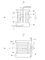
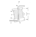
- FIG. 1 shows an optical fiber unit according to the first embodiment.
- FIG. 1A is a front view of the optical fiber unit
- FIG. 1B is a side view of the optical fiber unit.
- the optical fiber unit 1 includes an optical fiber 2, a vibration member 3 that vibrates in a vibration direction, a holding member 4, and a fixing portion 5.
- the vibration member 3 has a first end 3a and a second end 3b.
- the optical fiber 2 is fixed to the holding member 4 by the fixing portion 5.
- the entire length of the vibrating member 3 (hereinafter referred to as “full length”) changes.
- the change in the total length occurs in a direction A indicated by an arrow (hereinafter, “excitation direction A”). Examples of the change in the total length include the following (A), (B), and (C).
- (A) changes in the total length between the L SO and L LO.
- (B) the change in total length between the L NA and L LO.
- (C) Change in total length between LNA and LSO .
- LNA is the total length when no voltage is applied.
- L LO and L SO are the total lengths when a voltage is applied. Also, L SO ⁇ L NA ⁇ L LO . Total length in the voltage when the voltage and the total length of the case to be L SO of L LO, the sign of the voltage is reversed.
- the vibration member 3 expands and contracts in the vibration direction A. Stretching the optical fiber unit 1 is the change in the total length between the L NA and L LO.
- the first end 3a and the second end 3b are located away from each other in the excitation direction A.
- the vibration member 3 expands and contracts in the vibration direction A. Due to this expansion and contraction, vibration occurs in the excitation direction A. As a result, in the excitation direction A, the interval between the first end 3a and the second end 3b changes.
- the first holding part 4a is in contact with the first end part 3a.
- the second holding portion 4b is in contact with the second end portion 3b. Therefore, in the excitation direction A, the interval between the first holding unit 4a and the second holding unit 4b changes.
- the optical fiber 2 is fixed to the holding member 4.
- the fixing part 5 includes a first fixing part 5a and a second fixing part 5b.
- fixed part 5a is provided in the 1st holding
- fixed part 5b is provided in the 2nd holding
- the optical fiber 2 is fixed to the holding member 4 by adhesion, for example.
- the first fixing portion 5a and the second fixing portion 5b are each formed of a solidified adhesive.
- the optical fiber 2 is fixed to the first holding part 4a and the second holding part 4b. Therefore, the optical fiber 2 extends in the axial direction of the optical fiber 2 by the vibration member 3. As a result, the optical fiber 2 expands and contracts in the direction B indicated by the arrow. That is, the optical fiber 2 vibrates.
- coherent light The light from the coherent light source (hereinafter referred to as “coherent light”) can be incident on the optical fiber 2. Coherent light incident from one end of the optical fiber 2 exits from the other end of the optical fiber 2.
- the coherent light emitted from the optical fiber 2 can be used as illumination light, for example.
- the optical fiber 2 vibrates. Therefore, speckle can be reduced. As a result, even when coherent light is used as illumination light, illumination with little brightness unevenness can be achieved.
- the optical fiber 2 is fixed to the holding member 4 instead of the vibration member 3.
- the optical fiber 2 is fixed to the vibration member 3 with an adhesive, for example.
- the adhesive also adheres to the vibration member 3.
- the width of vibration is reduced as compared with the case where the adhesive is not attached.
- the optical fiber 2 is fixed to the vibration member 3.
- the elasticity of expansion / contraction with respect to the input signal is deteriorated. Therefore, speckle cannot be reduced sufficiently.
- illumination with very little unevenness in brightness cannot be achieved.
- the adhesive does not adhere to the vibration member 3 even if the optical fiber 2 is fixed with an adhesive. In this case, the width of vibration does not become small. Further, the optical fiber 2 is not fixed to the vibration member 3. In this case, the responsiveness of expansion / contraction with respect to the input signal does not deteriorate. Therefore, in the optical fiber unit 1, speckle can be sufficiently reduced. As a result, even if coherent light is used as illumination light, illumination with very little unevenness in brightness can be achieved.
- the optical fiber unit according to the second embodiment includes the above-described basic configuration, the holding member includes a third holding unit, and the third holding unit is positioned between the first holding unit and the second holding unit. And the fixing
- FIG. 2 shows an optical fiber unit according to the second embodiment.
- 2A is a front view of the optical fiber unit
- FIG. 2B is a side view of the optical fiber unit.
- the same components as those of the optical fiber unit 1 are denoted by the same reference numerals, and detailed description thereof is omitted.
- the optical fiber unit 10 has a third holding part 4c.
- the third holding part 4c is located between the first holding part 4a and the second holding part 4b.
- the first holding part 4a, the second holding part 4b, and the third holding part 4c may be integrally formed.
- a fixing portion 11 is provided on the third holding portion 4c.
- the third holding part 4c expands and contracts in the excitation direction A.
- the optical fiber 2 is fixed to the third holding part 4c. For this reason, the optical fiber 2 expands and contracts in the direction B. That is, the optical fiber 2 vibrates.
- the optical fiber 2 vibrates. Therefore, speckle can be reduced. As a result, even when coherent light is used as illumination light, illumination with little brightness unevenness can be achieved.
- the optical fiber 2 is fixed to the holding member 4 instead of the vibration member 3.
- the responsiveness of the optical fiber 2 to the vibration of the vibration member 3 does not deteriorate. Therefore, speckle can be further reduced.
- illumination light illumination with very little unevenness in brightness can be achieved.
- one fixed portion is provided in the third holding portion 4c.
- two fixing portions may be provided in the third holding portion 4c.
- the first holding unit has a first plane and a first side, the first plane is in contact with the first end, and the first side is the first plane. It is preferable that a fixed portion is provided on the first side surface in contact with the outer periphery of the first side surface and parallel to the excitation direction.
- the second holding unit has a second plane and a second side, the second plane is in contact with the second end, and the second side is the second side. It is preferable that a fixed portion is provided on the second side surface in contact with the outer periphery of the two planes and parallel to the excitation direction.
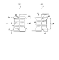
- FIG. 3 shows a perspective view of the optical fiber unit of the first embodiment.
- the first holding unit 4 a includes a first plane 12 and a first side surface 13.
- the first plane 12 is in contact with the first end 3a.
- the first side surface 13 is in contact with the outer periphery of the first plane 12 and is parallel to the excitation direction A.
- a first fixing portion 5 a is provided on the first side surface 13.
- the second holding portion 4 b has a second plane 14 and a second side surface 15.
- the second plane 14 is in contact with the second end 3b.
- the second side surface 15 is in contact with the outer periphery of the second plane 14 and is parallel to the excitation direction A.
- a second fixing portion 5 b is provided on the second side surface 15.
- maintenance part 4b is a cylinder.
- the first plane 12 and the second plane 14 are cylindrical bottom surfaces.
- the first side surface 13 and the second side surface 15 are cylindrical side surfaces.
- the shapes of the first holding part 4a and the second holding part 4b may be prisms.
- the first holding unit has a first plane and a first side, the first plane is in contact with the first end, and the first side is the first plane. It is preferable that the optical fiber is in contact with the first side surface in an arc and the fixing portion is provided on the first side surface.
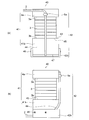
- FIG. 4A is a front view of the optical fiber unit
- FIG. 4B is a side view of the optical fiber unit.
- the same components as those of the optical fiber unit 1 are denoted by the same reference numerals, and detailed description thereof is omitted.
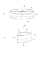
- the first holding unit is shown in FIG. Fig.5 (a) is a figure which shows an elliptic cylinder
- FIG.5 (b) is a perspective view of a 1st holding
- the optical fiber unit 20 includes a holding member 21 and a fixing portion 22.
- the holding member 21 includes a first holding part 21a and a second holding part 4b.
- the fixing part 22 includes a first fixing part 22a and a second fixing part 5b.
- maintenance part 21a is demonstrated using FIG.
- the elliptic cylinder 30 has a bottom surface 31, a bottom surface 32, and a side surface 33.
- maintenance part 21a is obtained by dividing the elliptic cylinder 30 into 4 equal parts.
- the first holding portion 21 a has a first plane 23 and a first side surface 24.
- the first plane 23 is a cut surface when the elliptic cylinder 30 is divided into four equal parts.
- the first side surface 24 is a part of the side surface 33.
- the first side surface 24 is in contact with the outer periphery 25.
- the outer periphery 25 is a part of the outer periphery of the first plane 23.
- the optical fiber 2 is in contact with the first side surface 24.
- the optical fiber 2 is not shown. Instead, an alternate long and short dash line is illustrated.
- the alternate long and short dash line indicates a tangent line between the optical fiber 2 and the first side surface 24. As indicated by the alternate long and short dash line, the optical fiber 2 is in contact with the first side surface 24 in an arc.
- the distance between the first flat surface 23 and the first side surface 24 increases as the distance from the outer periphery 25 increases. Therefore, the direction of the optical fiber 2 changes as the distance from the outer periphery 25 increases. Further, at the end portion 27, the distance between the first flat surface 23 and the first side surface 24 is maximized.
- the first side surface 24 is provided with a first fixing portion 22a.
- the optical fiber 2 is pressed between the first side face 24 and the first fixing part 22a.
- the first fixing portion 22a is fixed to the first holding portion 21a with the screw 26.
- the optical fiber 2 is fixed to the 1st holding
- the optical fiber unit 20 pressing and adhesion are used for fixing the optical fiber 2.
- the optical fiber 2 is fixed by pressing.
- the optical fiber 2 is fixed by adhesion.
- the vibration of the vibration member 3 cannot be efficiently applied to the optical fiber 2.
- the angle formed by the axial direction of the optical fiber 2 and the excitation direction A is approximately 0 °. In this case, slipping easily occurs between the optical fiber 2 and the first fixing portion 22a.
- the angle formed by the axial direction of the optical fiber 2 and the excitation direction A is approximately 90 °.
- the optical fiber 2 is pressed against each point by the pulling force from the vibration member 3 at each point from the outer periphery 25 to the end portion 27.
- an outward drag is generated in the optical fiber 2.
- slippage is unlikely to occur between the optical fiber 2 and the first fixing portion 22a. Therefore, the vibration of the vibrating member 3 can be efficiently applied to the optical fiber 2.
- the fixing portion is preferably disposed at a position where the angle formed by the axial direction of the optical fiber and the excitation direction is close to 90 °.
- the second holding unit has a second plane and a second side, the second plane is in contact with the second end, and the second side is the second plane. It is preferable that the optical fiber is in contact with a part of the outer periphery of the optical fiber, is in contact with the second side surface in an arc, and a fixing part is provided on the second side surface.
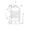
- FIG. 6A is a front view of the optical fiber unit
- FIG. 6B is a side view of the optical fiber unit.
- the same components as those of the optical fiber unit 1 are denoted by the same reference numerals, and detailed description thereof is omitted.
- the optical fiber unit 40 includes a holding member 41 and a fixing portion 42.
- the holding member 41 includes a first holding part 4a and a second holding part 41b.
- the fixing part 42 includes a first fixing part 5a and a second fixing part 42b.
- the second holding part 41 b is the same as the first holding part 21 a of the optical fiber unit 20.
- the second holding portion 41 b has a second flat surface 43 and a second side surface 44.
- the second plane 43 is a cut surface when the elliptic cylinder 30 is divided into four equal parts.
- the second side surface 44 is a part of the side surface 33.
- the second side surface 44 is in contact with the outer periphery 45.
- the outer periphery 45 is a part of the outer periphery of the second plane 43.
- the optical fiber 2 is in contact with the second side surface 44. Similar to the optical fiber unit 20, in the optical fiber unit 40, the optical fiber 2 is in contact with the second side surface 44 while drawing an arc.
- the distance between the second flat surface 43 and the second side surface 44 increases as the distance from the outer periphery 45 increases. Therefore, the direction of the optical fiber 2 changes as the distance from the outer periphery 45 increases. Further, the distance between the second flat surface 43 and the second side surface 44 is maximized at the end portion 47.
- the second side surface 44 is provided with a second fixing portion 42b.
- the optical fiber 2 is pressed between the second side surface 44 and the second fixing portion 42b.
- the second fixing portion 42 b is fixed to the second holding portion 41 b with the screw 46.
- the optical fiber 2 is fixed to the 2nd holding
- the optical fiber unit 40 pressing and adhesion are used for fixing the optical fiber 2.
- the optical fiber 2 is fixed by adhesion.
- the optical fiber 2 is fixed by pressing.
- the second fixing portion 42b is disposed in the vicinity of the end portion 47. Therefore, the angle formed by the axial direction of the optical fiber 2 and the excitation direction A is approximately 90 °. In this case, the optical fiber 2 is pressed against each point by the pulling force from the vibration member 3 at each point from the outer periphery 45 to the end portion 47. As a result, an outward drag is generated in the optical fiber 2. When an outward drag is generated, slippage is unlikely to occur between the optical fiber 2 and the second fixing portion 42b. Therefore, the vibration of the vibrating member 3 can be efficiently applied to the optical fiber 2.
- Fig. 7 shows an optical fiber unit of Modification 3.
- the same components as those of the optical fiber unit 20 and the same components as those of the optical fiber unit 40 are denoted by the same reference numerals, and detailed description thereof is omitted.
- the optical fiber unit 50 includes a holding member 51 and a fixing portion 52.
- the holding member 51 includes a first holding part 21a and a second holding part 41b.
- the fixing part 52 includes a first fixing part 22a and a second fixing part 42b.
- the angle formed by the axial direction of the optical fiber 2 and the excitation direction A is approximately 90 °.
- the optical fiber 2 is pressed against each point by the pulling force from the vibration member 3 at each point from the outer periphery 45 to the end portion 47.
- an outward drag is generated in the optical fiber 2.
- slipping is less likely to occur between the optical fiber 2 and the first fixing portion 22a or between the optical fiber 2 and the second fixing portion 42b. Therefore, the vibration of the vibrating member 3 can be efficiently applied to the optical fiber 2.
- FIG. 8A is a diagram of a first example of the first holding unit
- FIG. 8B is a diagram of a second example of the first holding unit.
- the first holding part of the first example and the first holding part of the second example can be used as the second holding part.
- the first side surface 24 of the optical fiber unit 40 and the second side surface 44 of the optical fiber unit 40 are smooth surfaces. However, as long as the optical fiber 2 draws an arc in contact with the surface, the surface in contact with the optical fiber 2 may not be a smooth surface.
- the holding member 60 has a side surface 61.
- the side surface 61 has minute irregularities on the surface.
- the side surface 61 is not a smooth surface.
- the side surface 61 is curved like the first side surface 24 and the second side surface 44.
- the optical fiber 2 contacts the side surface 61 while drawing an arc. Therefore, the side surface 61 can be used in place of the first side surface 24 and the second side surface 44.
- the interval between the irregularities varies irregularly.
- the depth of the concave portion and the height of the convex portion change irregularly.
- the interval between the irregularities, the depth of the concave portions, and the height of the convex portions may be changed regularly.
- the holding member 62 has a side surface 63.
- a curved groove 64 is formed on the side surface 63 as indicated by a broken line.
- the width and depth of the groove 64 may be any width and depth that does not cause the optical fiber 2 to be displaced. If the width of the groove 64 and the depth of the groove 64 are slightly larger than the diameter of the optical fiber 2, the optical fiber 2 can be stably held by the groove 64.
- the slip of the optical fiber 2 can be suppressed by the curved portion of the groove 64. Therefore, the vibration of the vibration member 3 can be efficiently applied to the optical fiber 2.
- the groove formed on the side surface 63 may be a linear groove.
- the side surface 63 is a curved surface like the first side surface 24 and the second side surface 44.
- the optical fiber 2 contacts the side surface 63 in an arc. Therefore, the side surface 63 can be used in place of the first side surface 24 and the second side surface 44.
- the first holding part has a first fixing part
- the second holding part has a second fixing part
- the space between the first fixing part and the second fixing part is preferably different from the excitation direction.
- FIG. 9 shows an optical fiber unit of Modification 4.
- the same components as those of the optical fiber unit 1 are denoted by the same reference numerals, and detailed description thereof is omitted.
- the excitation direction A and the direction B were parallel.
- the excitation direction A and the direction B are non-parallel. Therefore, the axial direction of the optical fiber 2 is different from the excitation direction A between the first fixing portion 5a and the second fixing portion 5b.
- the vibration of the vibrating member 3 can be applied to the optical fiber 2. Therefore, in the optical fiber unit 70, even if coherent light is used as illumination light, illumination with very little unevenness in brightness can be achieved.
- the first holding part has a first fixing part
- the second holding part has a second fixing part
- the optical fiber has the first fixing part or the second fixing part.
- the part is preferably fixed at least twice.
- FIG. 10 shows an optical fiber unit of Modification 5.
- the same components as those of the optical fiber unit 1 are denoted by the same reference numerals, and detailed description thereof is omitted.
- the optical fiber unit 80 includes a holding member 81 and a fixing portion 82.
- the holding member 81 includes a first holding part 81a and a second holding part 81b.
- the fixing part 82 includes a first fixing part 82a and a second fixing part 82b.
- the first holding portion 81a serves as the first fixing portion 82a.
- the second holding part 81b has a second fixing part 82b.
- the optical fiber may be fixed at least twice by the first fixing portion 82a or the second fixing portion 82b. By doing in this way, in the optical fiber unit 80, the length of the optical fiber 2 in which expansion and contraction occurs can be made longer than that of the optical fiber unit 1.
- speckles can be further reduced in the optical fiber unit 80 compared to the fiber unit 1. As a result, even if coherent light is used as illumination light, illumination with very little unevenness in brightness can be achieved.
- the optical fiber 2 is fixed twice by the first fixing portion 82a and fixed twice by the second fixing portion 82b. In this case, the optical fiber 2 makes one and a half rounds around the optical fiber unit 80. One end of the optical fiber 2 is located on the first holding portion 81a side, and the other end is located on the second holding portion 81b side.
- the optical fiber 2 may be fixed once by the first fixing portion 82a and fixed twice by the second fixing portion 82b. In this case, the optical fiber 2 goes around the optical fiber unit 80 once. One end and the other end of the optical fiber 2 are both positioned on the first holding portion 81a side or on the second holding portion 81b side.
- the optical fiber unit of the first embodiment it is preferable that the optical fiber is fixed in a state where tension is applied in the axial direction of the optical fiber.
- the optical fiber unit of Modification 6 the optical fiber is fixed in a state where tension is applied in the axial direction. Before describing the optical fiber unit of Modification 6, the optical fiber unit of the first embodiment will be described.
- FIG. 11 shows the optical fiber unit of the first embodiment.
- 11 (a) and 11 (c) are diagrams showing a state when no voltage is applied to the vibration member
- FIG. 11 (b) is a diagram showing a state when the entire length is extended.
- (D) is a figure which shows a mode when the full length has shrunk
- the same components as those of the optical fiber unit 1 are denoted by the same reference numerals, and detailed description thereof is omitted.
- a first fixing portion 5 a and a second fixing portion 5 b are illustrated as fixing portions of the optical fiber 2.
- the first fixing portion 5a and the second fixing portion 5b are not shown. Instead, arrows 90 and 91 are shown.
- An arrow 90 indicates a fixing point of the optical fiber 2 in the first holding unit 4a.
- An arrow 91 indicates a fixed point of the optical fiber 2 in the second holding unit 4b.
- the “fixed section” is between the arrow 90 and the arrow 91.
- the “section length” is the length of the optical fiber 2 in the fixed section.
- the “natural length” is a section length when the optical fiber 2 is fixed linearly in a state where no tension is applied in the axial direction.
- FIG. 11A the optical fiber 2 is fixed in a state in which no voltage is applied to the vibration member 3 and no tension is applied in the axial direction.
- the arrow 90 also moves by ⁇ 1 in the direction of the arrow A1.
- the second holding portion 4b does not move, the arrow 91 does not move. Therefore, the length M1 of the fixed section is M0 + ⁇ 1.
- the section length When the length M1 of the fixed section becomes L + ⁇ 1, the section length also becomes L + ⁇ 1. As described above, L represents the natural length. Therefore, when a voltage that extends the entire length is applied to the vibration member 3, the section length becomes longer by ⁇ 1 than the natural length.
- the optical fiber unit 1 when a voltage that extends the entire length is applied to the vibration member 3, a tension that tries to extend by ⁇ 1 in the direction of arrow A 1 is applied to the optical fiber 2. Due to this tension, the optical fiber 2 extends by ⁇ 1 in the direction of the arrow A1.
- a voltage that shortens the overall length is applied to the vibration member 3 from the state in which the optical fiber 2 is extended.
- the tension applied in the axial direction gradually decreases. Therefore, the optical fiber 2 gradually shrinks until the section length returns to the natural length L.
- the optical fiber 2 is fixed in a state where no voltage is applied to the vibration member 3 and in a state where no tension is applied in the axial direction.
- the arrow 90 As the first holding portion 4a moves, the arrow 90 also moves by ⁇ 2 in the direction of the arrow A2. On the other hand, since the second holding portion 4b does not move, the arrow 91 does not move. Therefore, the length M2 of the fixed section is M0 ⁇ 2. In this case, the length M2 of the fixed section is shorter than the natural length L.
- the length M2 of the fixed section becomes shorter than the natural length L.
- a compressive force that tends to shrink by ⁇ 2 in the direction of the arrow A2 is applied to the optical fiber 2.
- the optical fiber 2 is not fixed anywhere between the first holding part 4a and the second holding part 4b. For this reason, even if a compressive force is applied, the optical fiber 2 does not shrink and deforms between the first holding part 4a and the second holding part 4b.
- the optical fiber unit 1 when a voltage that reduces the overall length is applied to the vibration member 3 from a state in which no voltage is applied to the vibration member 3, the optical fiber 2 does not contract and the first holding unit It will deform
- FIG. 12A is a diagram illustrating the optical fiber unit of the first embodiment
- FIG. 12B is a diagram illustrating the optical fiber unit of Modification 6.
- the same components as those of the optical fiber unit 1 are denoted by the same reference numerals, and detailed description thereof is omitted.
- FIG. 12 (a) is the same as FIG. 11 (a) and FIG. 11 (c).
- the optical fiber 2 is fixed in a state where no voltage is applied to the vibration member 3 and no tension is applied in the axial direction.
- the optical fiber 2 is fixed to the first holding unit 4a and the second holding unit 4b.
- the optical fiber 2 is fixed in a state where no voltage is applied to the vibration member 3.
- the optical fiber 2 is fixed with tension applied in the axial direction. Specifically, as shown in FIG. 12 (b), tension is applied to the optical fiber 2 to extend it by ⁇ 2 in the direction of the arrow A1.
- the point 101 on the fiber 2 moves in the direction of the arrow A1.
- the point to which the point 101 has moved is a point 102 in FIG.
- the optical fiber 2 is fixed in a state in which no voltage is applied to the vibration member 3 and tension is applied in the axial direction.
- the arrow 90 As the first holding portion 4a moves, the arrow 90 also moves by ⁇ 2 in the direction of the arrow A2. On the other hand, since the second holding portion 4b does not move, the arrow 91 does not move. Therefore, the length M ′ of the fixed section is M0 ⁇ 2. In this case, similarly to the optical fiber unit 1, the length M ′ of the fixed section is shorter than the natural length L.
- the optical fiber 2 is fixed with tension applied in the axial direction. Further, the natural length L ′ in the optical fiber unit 100 is shorter than the natural length L. In this case, the tension applied in the axial direction gradually decreases until the length M ′ of the fixed section matches the natural length L ′. Therefore, the optical fiber 2 gradually shrinks until the section length returns to the natural length L ′.
- the length M ′ of the fixed section is natural even when a voltage that reduces the overall length is applied to the vibration member 3 from a state in which no voltage is applied to the vibration member 3. Until the length L ′ coincides, the optical fiber 2 is not deformed and contracts in the direction of the arrow A2.
- the optical fiber 2 can be extended in the direction of the arrow A1. Therefore, in the optical fiber unit 100, the expansion and contraction of the vibration member 3 can be efficiently converted into the vibration of the optical fiber 2.
- the tension in the axial direction of the optical fiber is zero or more in a state where the vibration member is most contracted.
- FIG. 13A is a diagram illustrating the optical fiber unit of the first embodiment
- FIG. 13B is a diagram illustrating the optical fiber unit of Modification 7.
- the same components as those of the optical fiber unit 1 are denoted by the same reference numerals, and detailed description thereof is omitted.
- FIG. 13 (a) is the same as FIG. 11 (a) and FIG. 11 (c).
- the optical fiber 2 is fixed in a state in which no voltage is applied to the vibration member 3 and no tension is applied in the axial direction.
- the optical fiber 2 is fixed to the first holding part 4a and the second holding part 4b.
- the optical fiber 2 is fixed in a state where no tension is applied in the axial direction.
- the optical fiber 2 is fixed in a state where a voltage is applied to the vibration member 3. Specifically, as shown in FIG. 13 (b), a voltage to be contracted by ⁇ 3 in the direction of arrow A 2 is applied to the vibration member 3. Thereby, as shown in FIG.13 (b), the full length shrinks
- the vibration member 3 is not applied with a voltage. Then, the total length extends by ⁇ 3 in the direction of arrow A1. By extending the entire length by ⁇ 3, the first holding portion 4a moves by ⁇ 3 in the direction of the arrow A1.
- the arrow 90 also moves by ⁇ 3 in the direction of the arrow A1.
- the arrow 91 does not move. Therefore, in a state where no voltage is applied to the vibration member 3, the optical fiber 2 is fixed in a state where tension is applied in the axial direction.
- the natural length L ′′ in the optical fiber unit 110 is shorter than the natural length L.
- the tension applied in the axial direction is not changed until the length M ′′ of the fixed section matches the natural length L ′′. Accordingly, the optical fiber 2 gradually shrinks until the section length returns to the natural length L ′′.
- the optical fiber 2 is fixed in a state where no voltage is applied to the vibration member 3 and tension is applied in the axial direction.
- the optical fiber 2 is fixed in a state in which no voltage is applied to the vibration member 3 and tension is applied in the axial direction. Therefore, in the optical fiber unit 110, the same effect as the optical fiber unit 100 is obtained.
- the length M ′′ of the fixed section is natural even when a voltage that reduces the overall length is applied to the vibration member 3 from a state in which no voltage is applied to the vibration member 3. Until the length L ′′ coincides, the optical fiber 2 is not deformed and contracts in the direction of the arrow A2.
- the optical fiber 2 can be extended in the direction of the arrow A1. Therefore, in the optical fiber unit 100, the expansion and contraction of the vibration member 3 can be efficiently converted into the vibration of the optical fiber 2.
- the optical fiber 2 is preferably fixed so that the tension in the axial direction becomes zero in a state where the vibration member is most contracted.
- the expansion / contraction of the vibration member when the expansion / contraction of the vibration member is converted into the vibration of the optical fiber 2, the expansion / contraction of the vibration member can be utilized to the maximum.
- the axial tension may be greater than zero in the state where the vibration member is most contracted.
- FIG. 14A is a diagram showing the first pattern
- FIG. 14B is a diagram showing the second pattern
- FIG. 14C is a diagram showing the third pattern.
- the horizontal axis indicates the voltage applied to the vibration member 3.
- the voltage in the range from zero to max is a voltage that extends the entire length.
- the voltage in the range from zero to min is a voltage that shortens the overall length.
- the vertical axis indicates the tension applied to the optical fiber 2. When the tension is zero, the section length matches the natural length.
- the first pattern is used for the optical fiber unit 1.
- the optical fiber 2 when a voltage that shortens the entire length is applied to the vibration member 3, the optical fiber 2 is deformed between the first holding part 4a and the second holding part 4b. Therefore, in the optical fiber unit 1, a voltage that reduces the overall length is not applied to the vibration member 3. Therefore, in the first pattern, only the voltage in the range from zero to max is applied to the vibration member 3.
- the optical fiber 2 is fixed in a state where no voltage is applied to the vibration member 3 and no tension is applied in the axial direction. Therefore, in the first pattern, when the voltage is zero, the expansion / contraction amount of the vibration member 3 is also zero. As described above, when the amount of expansion / contraction is zero, the total length matches the natural length.
- the second pattern is used for the optical fiber unit 100.
- a voltage that increases the total length and a voltage that decreases the total length can be applied to the vibration member 3. Therefore, in the second pattern, in addition to the voltage in the range from zero to max, the voltage in the range from min to zero is applied to the vibration member 3.
- the optical fiber 2 is fixed in a state where no voltage is applied to the vibration member 3, but is fixed in a state where a tension is applied in the axial direction. Therefore, in the second pattern, when the voltage applied to the vibration member 3 is zero, the vibration member 3 is extended.
- the third pattern is used for the optical fiber unit 110.
- a voltage that increases the total length and a voltage that decreases the total length can be applied to the vibration member 3. Therefore, in the third pattern, in addition to the voltage in the range from zero to max, the voltage in the range from min to zero is applied to the vibration member 3.
- the optical fiber 2 is fixed so that the tension in the axial direction becomes zero or more with the vibration member 3 being most contracted. Therefore, in a state where no voltage is applied to the vibration member 3, the optical fiber 2 is fixed in a state where tension is applied in the axial direction. Therefore, the third pattern is similar to the second pattern.
- FIG. 14 (c) shows a straight line indicated by a solid line and a straight line indicated by a broken line.
- the optical fiber 2 is fixed so that the axial tension is zero with the vibration member 3 being most contracted.
- the optical fiber 2 is fixed so that the axial tension becomes larger than zero in a state where the vibration member 3 is most contracted.
- the vibration member is preferably a laminated piezoelectric element.
- the optical fiber unit can be reduced in size.
- the illumination device includes a laser and the optical fiber unit according to the present embodiment.
- the illumination device of the present embodiment has an optical fiber unit that generates illumination light that is small in size and has sufficiently reduced speckles. Therefore, according to the illuminating device of the present embodiment, the illuminating device can be reduced in size and illumination light with sufficiently reduced speckle can be generated.
- the endoscope system includes an endoscope including an insertion unit, an imager disposed in the insertion unit, and the illumination device according to the present embodiment.
- FIG. 15 shows the endoscope system of the present embodiment.
- the endoscope system 200 includes an endoscope 201, an imager 202, and an illumination device 203.
- the endoscope 201 has an insertion unit 204.
- the insertion portion 204 includes a distal end hard portion 205, a bending portion 206, and a flexible tube portion 207.
- An imager 202 is disposed in the insertion unit 204.
- the lighting device 203 has a laser as a light source.
- the illuminating device 203 includes, for example, the optical fiber unit 1 shown in FIG. Laser light is incident from one end face of the optical fiber 2.
- the illuminating device 203 has a drive power supply which drives a vibration member.
- the endoscope system 200 includes a control device 208 and an image display unit 209.
- An endoscope 201, an illumination device 203, and an image display unit 209 are connected to the control device 208.
- the endoscope 201 is connected to the illumination device 203 and the control device 208 with a universal cord 210.
- a driving power source is used to drive the vibration member.
- a control unit is used to control the drive power supply.
- the driving power source and the control unit are not shown, they can be arranged in either the lighting device 203 or the control device 208, respectively.
- the endoscope 201 has an operation unit 211.
- the operation unit 211 includes a main body unit 212 and a grip unit 213.
- the main body 212 is provided with a treatment instrument insertion port 214.
- the gripping part 213 has a bending operation part 215 and a switch part 216.
- the switch unit 216 performs air supply, water supply, suction, and endoscopic photography.
- the endoscope system 200 has an illumination light source that generates illumination light that is small and has speckles sufficiently reduced. Therefore, according to the endoscope system 200, the system can be miniaturized, and observation with high contrast or an image with high contrast can be acquired.
- the laser is a pulse laser
- the timing of pulse emission and the vibration of the vibration member are synchronized with the frame rate of the imager
- the laser light source emits time and It is preferable that the time when the displacement speed of the vibrating member is maximized overlap at least once per frame.
- a laser can be used as a light source.
- the laser can be a pulsed laser.
- laser light is emitted intermittently.
- the light emission time in one injection is very short. Therefore, the brightness of the illumination light is determined by the light emission time and the number of times of emission.
- the illumination by the optical fiber unit and the imaging by the imager include the time when the displacement of the vibration member becomes zero.
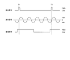
- FIG. 16 shows a light emission signal, a displacement signal, and an imaging signal.
- the light emission signal represents the light emission timing of the pulse laser.
- the emission signal becomes High, laser light is emitted from the pulse laser.
- the displacement signal has a maximum displacement speed when the displacement of the vibration member representing the change in displacement of the vibration member becomes zero.
- the imaging signal indicates the frame rate of the imaging element. Imaging is performed while the imaging signal is High.
- the light emission signal and the imaging signal are both high while the vibration member is displaced. Therefore, the light emission timing of the pulse laser and the vibration of the vibration member are synchronized with the frame rate of the imager.
- the displacement of the vibration member is zero. Therefore, at time T1, the time for which the pulse laser emits light and the time for which the displacement speed of the vibrating member is maximized overlap at least once per frame.
- the endoscope system it is possible to generate illumination light with sufficiently reduced speckles. As a result, observation with high contrast or an image with high contrast can be acquired.
- the present invention includes the following inventions.
- An excitation member having a first end and a second end; A holding member for holding the vibration member; A fixing portion for fixing the optical fiber to the holding member, The first end and the second end are located in the excitation direction,
- the holding member includes a first holding portion that contacts the first end portion, and a second holding portion that contacts the second end portion,
- the first holding part has a first fixing part
- the second holding part has a second fixing part
- a method of manufacturing an optical fiber unit wherein an optical fiber is fixed by a first fixing portion and a second fixing portion.
- Appendix 2 The method of manufacturing an optical fiber unit according to Additional Item 1, wherein the optical fiber is fixed at least twice by the first fixing portion and the second fixing portion.
- Item 3 The method for manufacturing an optical fiber unit according to Item 1, wherein the optical fiber is fixed in a state where tension is applied in an axial direction.
- Appendix 4 The optical fiber according to appendix 1, wherein the optical fiber is fixed by the first fixing portion and the second fixing portion, with the tension in the vibration member being most contracted, the axial tension being set to zero or more. Unit manufacturing method.
- the present invention is useful for an optical fiber unit, an illumination device, and an endoscope system in which speckle is sufficiently reduced.
Landscapes
- Physics & Mathematics (AREA)
- Optics & Photonics (AREA)
- Health & Medical Sciences (AREA)
- Life Sciences & Earth Sciences (AREA)
- Surgery (AREA)
- General Physics & Mathematics (AREA)
- Engineering & Computer Science (AREA)
- Medical Informatics (AREA)
- Radiology & Medical Imaging (AREA)
- Nuclear Medicine, Radiotherapy & Molecular Imaging (AREA)
- Biophysics (AREA)
- Biomedical Technology (AREA)
- Heart & Thoracic Surgery (AREA)
- Pathology (AREA)
- Molecular Biology (AREA)
- Animal Behavior & Ethology (AREA)
- General Health & Medical Sciences (AREA)
- Public Health (AREA)
- Veterinary Medicine (AREA)
- Instruments For Viewing The Inside Of Hollow Bodies (AREA)
Abstract
スペックルが十分に低減された光ファイバユニット、照明装置、及び内視鏡システムを提供する 光ファイバユニット1は、光ファイバ2と、加振方向に加振する加振部材3と、加振部材3を保持する保持部材4と、保持部材4に光ファイバ2を固定する固定部5と、を備え、加振部材3は、第1端部3aと、第2端部3bと、を有し、第1端部3aと第2端部3bは、加振方向に離れて位置し、保持部材4は、第1端部3aと接する第1保持部4aと、第2端部3bと接する第2保持部4bと、を有し、加振部材3によって、光ファイバ2が、光ファイバ2の軸方向に伸びる。
Description
本発明は、光ファイバユニット、照明装置、及び内視鏡システムに関する。
表面に凹凸を有する物体に照明光を照射すると、照明光が凹凸で散乱される。凹凸の大きさが光の波長程度で、照明光がレーザ光の場合、散乱されたレーザ光によってランダムな干渉が生じる。その結果、物体の表面に斑点模様が形成される。このような斑点模様をスペックルパターン、又は、単にスペックルという。スペックルが物体の表面に生じると、物体の表面の情報を正確に得られない。
レーザ光で物体を照明する装置として、光ファイバを用いた照明装置が知られている。光ファイバを用いた照明装置でも、スペックルは生じる。よって、スペックルの低減が必要になる。
スペックルを低減する方法として、光ファイバにねじりを加える方法や、光ファイバを側方から圧縮する方法が知られている。しかしながら、これらの方法では、スペックルを十分に低減できない。
特許文献1には、光ファイバを用いた照明装置が開示されている。この照明装置では、光ファイバの軸方向に沿って、圧電体が貼り付けられている。圧電体を振動させることで、光ファイバが振動する。その結果、スペックルが低減される。
特許文献1に開示された照明装置では、所定長の光ファイバが、圧電体に貼り付けられている。この場合、圧電体の振動に対する光ファイバの応答性が低下する。そのため、スペックルを十分に低減できない。
本発明は、このような課題に鑑みてなされたものであって、スペックルが十分に低減された光ファイバユニット、照明装置、及び内視鏡システムを提供することを目的とする。
上述した課題を解決し、目的を達成するために、本発明の少なくとも幾つかの実施形態に係る光ファイバユニットは、
光ファイバと、
加振方向に加振する加振部材と、
加振部材を保持する保持部材と、
保持部材に光ファイバを固定する固定部と、を備え、
加振部材は、第1端部と、第2端部と、を有し、
第1端部と第2端部は、加振方向に離れて位置し、
保持部材は、第1端部と接する第1保持部と、第2端部と接する第2保持部と、を有し、
加振部材によって、光ファイバが、光ファイバの軸方向に伸びることを特徴とする。
光ファイバと、
加振方向に加振する加振部材と、
加振部材を保持する保持部材と、
保持部材に光ファイバを固定する固定部と、を備え、
加振部材は、第1端部と、第2端部と、を有し、
第1端部と第2端部は、加振方向に離れて位置し、
保持部材は、第1端部と接する第1保持部と、第2端部と接する第2保持部と、を有し、
加振部材によって、光ファイバが、光ファイバの軸方向に伸びることを特徴とする。
また、本発明の少なくとも幾つかの実施形態に係る照明装置は、
レーザと、
上述の光ファイバユニットと、を有することを特徴とする。
レーザと、
上述の光ファイバユニットと、を有することを特徴とする。
また、本発明の少なくとも幾つかの実施形態に係る内視鏡システムは、
挿入部を備えた内視鏡と、
挿入部に配置されたイメージャと、
上述の照明装置と、を備えることを特徴とする。
挿入部を備えた内視鏡と、
挿入部に配置されたイメージャと、
上述の照明装置と、を備えることを特徴とする。
本発明によれば、スペックルが十分に低減された光ファイバユニット、照明装置、及び内視鏡システムを提供することができる。
実施例の説明に先立ち、本発明のある態様にかかる実施形態の作用効果を説明する。なお、本実施形態の作用効果を具体的に説明するに際しては、具体的な例を示して説明することになる。しかし、後述する実施例の場合と同様に、それらの例示される態様はあくまでも本発明に含まれる態様のうちの一部に過ぎず、その態様には数多くのバリエーションが存在する。したがって、本発明は例示される態様に限定されるものではない。
本実施形態の光ファイバユニットは、基本構成として、光ファイバと、加振方向に加振する加振部材と、加振部材を保持する保持部材と、保持部材に光ファイバを固定する固定部と、を備える。また、基本構成では、加振部材は、第1端部と、第2端部と、を有し、第1端部と第2端部は、加振方向に離れて位置し、保持部材は、第1端部と接する第1保持部と、第2端部と接する第2保持部と、を有し、加振部材によって、光ファイバが、光ファイバの軸方向に伸びる。
第1実施形態の光ファイバユニットは、上述の基本構成を備えると共に、固定部は、第1保持部と第2保持部の少なくとも一方に設けられている。
第1実施形態の光ファイバユニットを図1に示す。図1(a)は、光ファイバユニットの正面図、図1(b)は、光ファイバユニットの側面図である。
光ファイバユニット1は、光ファイバ2と、加振方向に加振する加振部材3と、保持部材4と、固定部5と、を備える。加振部材3は、第1端部3aと、第2端部3bと、を有する。固定部5によって、光ファイバ2が保持部材4に固定されている。
加振部材3では、例えば、電圧を加えることで、加振部材3の全長(以下、「全長」という)が変化する。全長の変化は、矢印で示す方向A(以下、「加振方向A」)で生じる。全長の変化としては、例えば、以下の(A)、(B)、及び(C)がある。
(A)LSOとLLOとの間での全長の変化。
(B)LNAとLLOとの間での全長の変化。
(C)LNAとLSOとの間での全長の変化。
(B)LNAとLLOとの間での全長の変化。
(C)LNAとLSOとの間での全長の変化。
LNAは、電圧を加えない状態における全長である。LLOとLSOは、電圧を加えた状態における全長である。また、LSO<LNA<LLOである。全長がLSOになる場合の電圧と全長がLLOの場合の電圧とでは、電圧の符号が逆になっている。
電圧を加えない状態を基準にすると、(A)では、全長は伸び縮みしている。(B)では、全長は伸びているが、縮んではいない。また、(C)では、全長は縮んでいるが、伸びてはいない。しかしながら、以下の説明における「伸縮」には、上述の(A)、(B)、及び(C)が含まれるものとする。
光ファイバユニット1では、加振部材3は、加振方向Aに伸縮する。光ファイバユニット1における伸縮は、LNAとLLOとの間での全長の変化である。
第1端部3aと第2端部3bは、加振方向Aに離れて位置している。上述のように、加振部材3は、加振方向Aに伸縮する。この伸縮によって、加振方向Aで振動が生じる。その結果、加振方向Aにおいて、第1端部3aと第2端部3bとの間隔が変化する。
第1保持部4aは、第1端部3aと接している。第2保持部4bは、第2端部3bと接している。よって、加振方向Aにおいて、第1保持部4aと第2保持部4bとの間隔が変化する。
光ファイバ2は、保持部材4に固定されている。光ファイバユニット1では、固定部5は、第1固定部5aと、第2固定部5bと、を有する。第1固定部5aは、第1保持部4aに設けられている。第2固定部5bは、第2保持部4bに設けられている。
光ファイバ2は、例えば、接着で保持部材4に固定されている。この場合、第1固定部5aと第2固定部5bは、各々、固化した接着剤で形成されている。
上述のように、加振方向Aにおいて、第1保持部4aと第2保持部4bとの間隔が変化する。光ファイバ2は、第1保持部4aと第2保持部4bに固定されている。そのため、加振部材3によって、光ファイバ2が、光ファイバ2の軸方向に伸びる。その結果、光ファイバ2では、矢印で示す方向Bに伸縮が生じる。すなわち、光ファイバ2が振動する。
光ファイバ2には、コヒーレント光源からの光(以下「コヒーレント光」という)を入射させることできる。光ファイバ2の一端から入射したコヒーレント光は、光ファイバ2の他端から出射する。
光ファイバ2から出射したコヒーレント光は、例えば、照明光として用いることができる。光ファイバユニット1では、光ファイバ2が振動している。そのため、スペックルを低減できる。その結果、コヒーレント光を照明光として用いても、明るさのムラが少ない照明ができる。
更に、光ファイバユニット1では、光ファイバ2は、加振部材3ではなく、保持部材4に固定されている。
光ファイバ2が、例えば、接着剤で加振部材3に固定されているとする。この場合、加振部材3にも接着剤が付着する。加振部材3に接着剤が付着すると、接着剤が付着していない場合に比べて、振動の幅が小さくなる。また、光ファイバ2が、加振部材3に固定されている。この場合、入力信号に対する伸縮の応答性が悪くなる。そのため、スペックルを十分に低減できない。その結果、コヒーレント光を照明光として用いると、明るさのムラが非常に少ない照明ができない。
これに対して、光ファイバ2が保持部材4に固定されていると、接着剤で光ファイバ2を固定しても、加振部材3には接着剤が付着しない。この場合、振動の幅は小さくならない。また、光ファイバ2は加振部材3に固定されていない。この場合、入力信号に対する伸縮の応答性は悪化しない。そのため、光ファイバユニット1では、スペックルを十分に低減できる。その結果、コヒーレント光を照明光として用いても、明るさのムラが非常に少ない照明ができる。
第2実施形態の光ファイバユニットは、上述の基本構成を備えると共に、保持部材は、第3保持部を有し、第3保持部は、第1保持部と第2保持部との間に位置し、固定部は、第3保持部に設けられている。
第2実施形態の光ファイバユニットを図2に示す。図2(a)は、光ファイバユニットの正面図、図2(b)は、光ファイバユニットの側面図である。光ファイバユニット1と同じ構成要素には同じ番号を付し、詳細な説明は省略する。
光ファイバユニット10は、第3保持部4cを有する。第3保持部4cは、第1保持部4aと第2保持部4bとの間に位置している。第1保持部4a、第2保持部4b、及び第3保持部4cは、一体に形成されていても良い。第3保持部4cに、固定部11が設けられている。
上述のように、加振方向Aにおいて、第1保持部4aと第2保持部4bとの間隔が変化する。そのため、第3保持部4cでは、加振方向Aにおいて伸縮が生じる。光ファイバ2は、第3保持部4cに固定されている。そのため、光ファイバ2では、方向Bに伸縮が生じる。すなわち、光ファイバ2が振動する。
このように、光ファイバユニット10でも、光ファイバ2が振動している。そのため、スペックルを低減できる。その結果、コヒーレント光を照明光として用いても、明るさのムラが少ない照明ができる。
光ファイバユニット10でも、光ファイバ2は、加振部材3ではなく、保持部材4に固定されている。この場合、加振部材3の振動に対する光ファイバ2の応答性が低下しない。そのため、スペックルを更に低減できる。その結果、コヒーレント光を照明光として用いても、明るさのムラが非常に少ない照明ができる。
光ファイバユニット10では、1つの固定部が第3保持部4cに設けられている。しかしながら、破線で示すように、2つの固定部を第3保持部4cに設けても良い。
第1実施形態の光ファイバユニットでは、第1保持部は、第1平面と、第1側面と、を有し、第1平面は、第1端部と接し、第1側面は、第1平面の外周と接し、且つ、加振方向と平行であり、第1側面に、固定部が設けられていることが好ましい。
また、第1実施形態の光ファイバユニットでは、第2保持部は、第2平面と、第2側面と、を有し、第2平面は、第2端部と接し、第2側面は、第2平面の外周と接し、且つ、加振方向と平行であり、第2側面に、固定部が設けられていることが好ましい。
第1実施形態の光ファイバユニットの斜視図を図3に示す。光ファイバユニット1では、第1保持部4aは、第1平面12と、第1側面13と、を有する。第1平面12は、第1端部3aと接している。第1側面13は、第1平面12の外周と接し、且つ、加振方向Aと平行である。第1側面13に、第1固定部5aが設けられている。
また、第2保持部4bは、第2平面14と、第2側面15と、を有する。第2平面14は、第2端部3bと接している。第2側面15は、第2平面14の外周と接し、且つ、加振方向Aと平行である。第2側面15に、第2固定部5bが設けられている。
図3では、第1保持部4aと第2保持部4bの形状は、円柱である。第1平面12と第2平面14は、円柱の底面である。第1側面13と第2側面15は、円柱の側面である。第1保持部4aと第2保持部4bの形状は、角柱であっても良い。
第1実施形態の光ファイバユニットでは、第1保持部は、第1平面と、第1側面と、を有し、第1平面は、第1端部と接し、第1側面は、第1平面の外周の一部と接し、光ファイバは、弧を描いて第1側面に接し、第1側面に、固定部が設けられていることが好ましい。
変形例1の光ファイバユニットを図4に示す。図4(a)は、光ファイバユニットの正面図、図4(b)は、光ファイバユニットの側面図である。光ファイバユニット1と同じ構成要素には同じ番号を付し、詳細な説明は省略する。また、第1保持部を図5に示す。図5(a)は、楕円柱を示す図、図5(b)は、第1保持部の斜視図である。
光ファイバユニット20は、保持部材21と、固定部22と、を備える。保持部材21は、第1保持部21aと、第2保持部4bと、を有する。固定部22は、第1固定部22aと、第2固定部5bと、を有する。
第1保持部21aについて、図5を用いて説明する。楕円柱30は、底面31と、底面32と、側面33と、を有する。第1保持部21aは、楕円柱30を4等分することで得られる。
第1保持部21aは、第1平面23と、第1側面24と、を有する。第1平面23は、楕円柱30を4等分したときの切断面である。第1側面24は、側面33の一部である。第1側面24は、外周25と接している。外周25は、第1平面23の外周の一部である。
光ファイバ2は、第1側面24に接している。図5(b)では、光ファイバ2は図示されていない。その代わりに、一点鎖線が図示されている、一点鎖線は、光ファイバ2と第1側面24との接線を示している。一点鎖線が示すように、光ファイバ2は、弧を描いて第1側面24に接している。
第1保持部21aでは、第1平面23と第1側面24との間隔は、外周25から離れるにつれて広がっている。そのため、光ファイバ2の向きは、外周25から離れるにつれて変化する。また、端部27で、第1平面23と第1側面24との間隔が最大になる。
図4(a)に戻って説明する。第1側面24には、第1固定部22aが設けられている。第1保持部21aでは、第1側面24と第1固定部22aとの間で、光ファイバ2が押圧される。この状態で、第1固定部22aは、ねじ26で第1保持部21aに固定される。これにより、光ファイバ2が第1保持部21aに固定される。
光ファイバユニット20では、光ファイバ2の固定に、押圧と接着が用いられている。第1保持部21aでは、押圧で光ファイバ2が固定されている。第2保持部4bでは、接着で光ファイバ2が固定されている。
押圧による固定の場合、光ファイバ2と第1固定部22aとの間で滑りが生じると、加振部材3の振動を、効率良く光ファイバ2に与えられない。例えば、第1固定部22aを外周25の近傍に配置すると、光ファイバ2の軸方向と加振方向Aとのなす角度がほぼ0°になる。この場合、光ファイバ2と第1固定部22aとの間で滑りが生じ易くなる。
一方、第1固定部22aを端部27の近傍に配置すると、光ファイバ2の軸方向と加振方向Aとのなす角度がほぼ90°になる。この場合、外周25から端部27までの間各点で、光ファイバ2は加振部材3からの引っ張り力によって各点に押しつけられる。その結果、光ファイバ2には、外向きの抗力が発生する。外向きの抗力が発生すると、光ファイバ2と第1固定部22aとの間で滑りが生じにくくなる。そのため、加振部材3の振動を、効率良く光ファイバ2に与えられる。
このように、押圧で光ファイバ2を固定する場合、固定部は、光ファイバの軸方向と加振方向とのなす角度が90°に近くなる場所に配置すると良い。
第1実施形態の光ファイバユニットでは、第2保持部は、第2平面と、第2側面と、を有し、第2平面は、第2端部と接し、第2側面は、第2平面の外周の一部と接し、光ファイバは、弧を描いて第2側面に接し、第2側面に、固定部が設けられていることが好ましい。
変形例2の光ファイバユニットを図6に示す。図6(a)は、光ファイバユニットの正面図、図6(b)は、光ファイバユニットの側面図である。光ファイバユニット1と同じ構成要素には同じ番号を付し、詳細な説明は省略する。
光ファイバユニット40は、保持部材41と、固定部42と、を備える。保持部材41は、第1保持部4aと、第2保持部41bと、を有する。固定部42は、第1固定部5aと、第2固定部42bと、を有する。
第2保持部41bは、光ファイバユニット20の第1保持部21aと同一である。第2保持部41bは、第2平面43と、第2側面44と、を有する。第2平面43は、楕円柱30を4等分したときの切断面である。第2側面44は、側面33の一部である。第2側面44は、外周45と接している。外周45は、第2平面43の外周の一部である。
光ファイバ2は、第2側面44に接している。光ファイバユニット20と同様に、光ファイバユニット40でも、光ファイバ2は、弧を描いて第2側面44に接している。
第2保持部41bでは、第2平面43と第2側面44との間隔は、外周45から離れるにつれて広がっている。そのため、光ファイバ2の向きは、外周45から離れるにつれて変化する。また、端部47で、第2平面43と第2側面44との間隔が最大になる。
第2側面44には、第2固定部42bが設けられている。第2保持部41bでは、第2側面44と第2固定部42bとの間で、光ファイバ2が押圧される。この状態で、第2固定部42bは、ねじ46で第2保持部41bに固定される。これにより、光ファイバ2が第2保持部41bに固定される。
光ファイバユニット40では、光ファイバ2の固定に、押圧と接着が用いられている。第1保持部4aでは、接着で光ファイバ2が固定されている。第2保持部41bでは、押圧で光ファイバ2が固定されている。
光ファイバユニット40では、第2固定部42bが端部47の近傍に配置されている。よって、光ファイバ2の軸方向と加振方向Aとのなす角度がほぼ90°になる。この場合、外周45から端部47までの間各点で、光ファイバ2は加振部材3からの引っ張り力によって各点に押しつけられる。その結果、光ファイバ2には、外向きの抗力が発生する。外向きの抗力が発生すると、光ファイバ2と第2固定部42bとの間で滑りが生じにくくなる。そのため、加振部材3の振動を、効率良く光ファイバ2に与えられる。
変形例3の光ファイバユニットを図7に示す。光ファイバユニット20と同じ構成要素や光ファイバユニット40と同じ構成要素には同じ番号を付し、詳細な説明は省略する。
光ファイバユニット50は、保持部材51と、固定部52と、を備える。保持部材51は、第1保持部21aと、第2保持部41bと、を有する。固定部52は、第1固定部22aと、第2固定部42bと、を有する。
光ファイバユニット50では、光ファイバ2の軸方向と加振方向Aとのなす角度がほぼ90°になる。この場合、外周45から端部47までの間各点で、光ファイバ2は加振部材3からの引っ張り力によって各点に押しつけられる。その結果、光ファイバ2には、外向きの抗力が発生する。外向きの抗力が発生すると、光ファイバ2と第1固定部22aとの間や、光ファイバ2と第2固定部42bとの間で滑りが生じにくくなる。そのため、加振部材3の振動を、効率良く光ファイバ2に与えられる。
別の第1保持部を図8に示す。図8(a)は、第1保持部の第1例の図、図8(b)は、第1保持部の第2例の図である。第1例の第1保持部と第2例の第1保持部は、第2保持部として使用できる。
光ファイバユニット40の第1側面24や、光ファイバユニット40の第2側面44は、滑らかな面である。しかしながら、面と接した状態で光ファイバ2が弧を描いていれば、光ファイバ2が接する面は滑らかな面で無くても良い。
第1例では、保持部材60は、側面61を有する。側面61は、表面に微小な凹凸を有する。このように、側面61は滑らかな面ではない。しかしながら、大まかに見ると、側面61は、第1側面24や第2側面44と同様に、曲面になっている。この場合、光ファイバ2は、弧を描いて側面61に接する。よって、側面61を、第1側面24や第2側面44の代わりに用いることができる。
側面61では、凹凸の間隔は不規則に変化している。また、凹部の深さや凸部の高さも、不規則に変化している。しかしながら、凹凸の間隔、凹部の深さ、及び凸部の高さは、規則的に変化していても良い。
第2例では、保持部材62は、側面63を有する。側面63には、破線で示すように、曲線状の溝64が形成されている。溝64の幅と溝の深さは、光ファイバ2が位置ずれしない程度の幅と深さであれば良い。溝64の幅と溝64の深さを、光ファイバ2の直径より若干大きくすると、溝64で光ファイバ2を安定して保持できる。
側面63では、溝64の曲線部分で、光ファイバ2の滑りを抑制できる。よって、加振部材3の振動を、効率良く光ファイバ2に与えられる。側面63に形成される溝は、直線状の溝であっても良い。
側面63は、第1側面24や第2側面44と同様に、曲面になっている。溝64の深さを一定にすると、光ファイバ2は弧を描いて側面63に接する。よって、側面63を、第1側面24や第2側面44の代わりに用いることができる。
第1実施形態の光ファイバユニットでは、第1保持部は、第1固定部を有し、第2保持部は、第2固定部を有し、第1固定部から第2固定部までの間で、光ファイバの軸方向は、加振方向とは異なることが好ましい。
変形例4の光ファイバユニットを図9に示す。光ファイバユニット1と同じ構成要素には同じ番号を付し、詳細な説明は省略する。
光ファイバユニット1では、加振方向Aと方向Bとが平行であった。これに対して、光ファイバユニット70では、加振方向Aと方向Bとが非平行になっている。そのため、第1固定部5aから第2固定部5bまでの間で、光ファイバ2の軸方向は、加振方向Aとは異なる。
この場合でも、加振部材3の振動を、光ファイバ2に与えられる。よって、光ファイバユニット70では、コヒーレント光を照明光として用いても、明るさのムラが非常に少ない照明ができる。
第1実施形態の光ファイバユニットでは、第1保持部は、第1固定部を有し、第2保持部は、第2固定部を有し、光ファイバは、第1固定部又は第2固定部で、少なくとも2回固定されていることが好ましい。
変形例5の光ファイバユニットを図10に示す。光ファイバユニット1と同じ構成要素には同じ番号を付し、詳細な説明は省略する。
光ファイバユニット80は、保持部材81と、固定部82と、を備える。保持部材81は、第1保持部81aと、第2保持部81bと、を有する。固定部82は、第1固定部82aと、第2固定部82bと、を有する。第1保持部81aは、第1固定部82aする。第2保持部81bは、第2固定部82bを有する。
光ファイバは、第1固定部82a又は第2固定部82bで、少なくとも2回固定されていると良い。このようにすることで、光ファイバユニット80では、伸縮が生じる光ファイバ2の長さを、光ファイバユニット1に比べて長くできる。
そのため、光ファイバユニット80では、ファイバユニット1に比べてスペックルを更に低減できる。その結果、コヒーレント光を照明光として用いても、明るさのムラが非常に少ない照明ができる。
光ファイバユニット80では、光ファイバ2は、第1固定部82aで2回固定され、第2固定部82bで2回固定されている。この場合、光ファイバ2は、光ファイバユニット80の周りを1周半する。光ファイバ2の一端は第1保持部81a側に位置し、他端は第2保持部81b側に位置する。
光ファイバ2は、第1固定部82aで1回固定され、第2固定部82bで2回固定されていても良い。この場合、光ファイバ2は、光ファイバユニット80の周りを1周する。光ファイバ2の一端と他端は、共に、第1保持部81a側に位置するか、又は第2保持部81b側に位置する。
第1実施形態の光ファイバユニットでは、光ファイバは、光ファイバの軸方向に張力が加わった状態で固定されていることが好ましい。
変形例6の光ファイバユニットでは、光ファイバは、軸方向に張力が加わった状態で固定されている。変形例6の光ファイバユニットを説明する前に、第1実施形態の光ファイバユニットについて、説明する。
第1実施形態の光ファイバユニットを図11に示す。図11(a)と図11(c)は、加振部材に電圧が加えられていないときの様子を示す図、図11(b)は、全長が伸びたときの様子を示す図、図11(d)は、全長が縮んだときの様子を示す図である。光ファイバユニット1と同じ構成要素には同じ番号を付し、詳細な説明は省略する。
図1では、光ファイバ2の固定部として、第1固定部5aと第2固定部5bが図示されている。一方、例えば図11(a)では、第1固定部5aと第2固定部5bは図示されていない。その代わりに、矢印90と矢印91が図示されている。矢印90は、第1保持部4aにおける光ファイバ2の固定点を示している。矢印91は、第2保持部4bにおける光ファイバ2の固定点を示している。
以下では、「固定区間」、「区間長」、及び「自然長」を用いて説明する。「固定区間」は、矢印90と矢印91との間である。「区間長」は、固定区間における光ファイバ2の長さである。「自然長」は、軸方向に張力が加わっていない状態で、光ファイバ2が直線状に固定されているときの区間長である。
図11(a)と図11(b)について説明する。図11(a)では、光ファイバ2は、加振部材3に電圧が加えられていない状態で、且つ、軸方向に張力が加わっていない状態で固定されている。
この状態から、加振部材3に、全長が伸びるような電圧を加える。そうすると、図11(b)に示すように、全長は、矢印A1の方向に、Δ1だけ伸びる。全長がΔ1だけ伸びることで、第1保持部4aが、矢印A1の方向に、Δ1だけ移動する。
第1保持部4aの移動に伴って、矢印90も、矢印A1の方向に、Δ1だけ移動する。一方、第2保持部4bは移動しないので、矢印91は移動しない。よって、固定区間の長さM1は、M0+Δ1になる。
固定区間の長さM1がL+Δ1になると、区間長もL+Δ1になる。上述のように、Lは自然長を表している。よって、加振部材3に全長が伸びるような電圧が加えられると、区間長は自然長よりもΔ1だけ長くなる。
このように、光ファイバユニット1では、加振部材3に全長が伸びるような電圧が加えられると、矢印A1の方向にΔ1だけ伸ばそうとする張力が、光ファイバ2に加えられる。この張力によって、光ファイバ2は、矢印A1の方向に、Δ1だけ伸びる。
光ファイバ2が伸びた状態から、全長が縮むような電圧を加振部材3に加える。この場合、固定区間の長さM1が自然長Lと一致するまでの間では、軸方向に加えられていた張力が、徐々に小さくなる。よって、区間長が自然長Lに戻るまでの間、光ファイバ2は、徐々に縮んでいく。
図11(c)と図11(d)について説明する。図11(c)では、光ファイバ2は、加振部材3に電圧が加えられていない状態で、且つ、軸方向に張力が加わっていない状態で固定されている。
この状態から、加振部材3に、全長が縮むような電圧を加える。そうすると、図11(d)に示すように、全長は、矢印A2の方向に、Δ2だけ縮む。全長がΔ2だけ縮むことで、第1保持部4aが、矢印A2の方向に、Δ2だけ移動する。
第1保持部4aの移動に伴って、矢印90も、矢印A2の方向に、Δ2だけ移動する。一方、第2保持部4bは移動しないので、矢印91は移動しない。よって、固定区間の長さM2は、M0-Δ2になる。この場合、固定区間の長さM2は、自然長Lよりも短くなる。
上述のように、光ファイバ2が伸びた状態から、全長が縮むような電圧を加振部材3に加えると、軸方向に加えられていた張力が、徐々に小さくなるだけである。よって、この場合、光ファイバ2を縮めようとする力、すなわち、圧縮力は生じない。
一方、加振部材3に電圧が加えられていない状態から、全長が縮むような電圧を加振部材3に加えると、固定区間の長さM2は、自然長Lよりも短くなる。この場合、矢印A2の方向にΔ2だけ縮めようとする圧縮力が、光ファイバ2に加えられる。
しかしながら、第1保持部4aと第2保持部4bとの間では、光ファイバ2はどこにも固定されていない。そのため、圧縮力が加わっても、光ファイバ2は縮まず、第1保持部4aと第2保持部4bとの間で変形してしまう。
このように、光ファイバユニット1では、加振部材3に電圧が加えられていない状態から、全長が縮むような電圧を加振部材3に加えると、光ファイバ2は縮まず、第1保持部4aと第2保持部4bとの間で変形してしまう。
変形例6の光ファイバユニットについて説明する。変形例6の光ファイバユニットを図12に示す。図12(a)は、第1実施形態の光ファイバユニットを示す図、図12(b)は、変形例6の光ファイバユニットを示す図である。光ファイバユニット1と同じ構成要素には同じ番号を付し、詳細な説明は省略する。
図12(a)は、図11(a)や図11(c)と同じ図である。図12(a)では、光ファイバ2は、加振部材3に電圧が加えられていない状態で、且つ、軸方向に張力が加わっていない状態で固定されている。
一方、光ファイバユニット100でも、光ファイバ2は、第1保持部4aと第2保持部4bに固定されている。また、光ファイバ2は、加振部材3に電圧が加えられていない状態で固定されている。
ただし、光ファイバユニット100では、光ファイバ2は、軸方向に張力が加わった状態で固定されている。具体的には、図12(b)に示すように、矢印A1の方向にΔ2だけ伸ばそうとする張力が、光ファイバ2に加えられている。
ファイバユニット1において、ファイバ2を矢印A1の方向に伸ばすと、ファイバ2上の点101は、矢印A1の方向に移動する。点101が移動した点が、図12(b)における点102である。
光ファイバユニット100では、光ファイバ2は、加振部材3に電圧が加えられていない状態で、且つ、軸方向に張力が加わった状態で固定されている。
この状態から、加振部材3に、全長が縮むような電圧を加える。そうすると、全長は、矢印A2の方向に、Δ2だけ縮む。全長がΔ2だけ縮むことで、第1保持部4aが、矢印A2の方向に、Δ2だけ移動する。
第1保持部4aの移動に伴って、矢印90も、矢印A2の方向に、Δ2だけ移動する。一方、第2保持部4bは移動しないので、矢印91は移動しない。よって、固定区間の長さM’は、M0-Δ2になる。この場合、光ファイバユニット1と同様に、固定区間の長さM’は、自然長Lよりも短くなる。
しかしながら、光ファイバユニット100では、光ファイバ2は、軸方向に張力が加わった状態で固定されている。また、光ファイバユニット100における自然長L’は、自然長Lよりも短い。この場合、固定区間の長さM’が自然長L’と一致するまでの間では、軸方向に加えられていた張力が、徐々に小さくなる。よって、区間長が自然長L’に戻るまでの間、光ファイバ2は、徐々に縮んでいく。
光ファイバユニット1では、加振部材3に電圧が加えられていない状態から、全長が縮むような電圧を加振部材3に加えると、図11(d)に示すように、光ファイバ2は、第1保持部4aと第2保持部4bとの間で変形してしまう。
これに対して、光ファイバユニット100では、加振部材3に電圧が加えられていない状態から、全長が縮むような電圧を加振部材3に加えても、固定区間の長さM’が自然長L’と一致するまでは、光ファイバ2は変形すること無く、矢印A2の方向に縮む。
また、全長が伸びるような電圧を加振部材3に加えることで、光ファイバ2を、矢印A1の方向に伸ばすこができる。よって、光ファイバユニット100では、加振部材3の伸縮を、効率良く、光ファイバ2の振動に変換できる。
第1実施形態の光ファイバユニットでは、加振部材が最も縮んだ状態で、光ファイバの軸方向の張力がゼロ以上であることが好ましい。
変形例7の光ファイバユニットについて説明する。変形例7の光ファイバユニットを図13に示す。図13(a)は、第1実施形態の光ファイバユニットを示す図、図13(b)は、変形例7の光ファイバユニットを示す図である。光ファイバユニット1と同じ構成要素には同じ番号を付し、詳細な説明は省略する。
図13(a)は、図11(a)や図11(c)と同じ図である。図13(a)では、光ファイバ2は、加振部材3に電圧が加えられていない状態で、且つ、軸方向に張力が加わっていない状態で固定されている。
一方、光ファイバユニット110でも、光ファイバ2は、第1保持部4aと第2保持部4bに固定されている。また、光ファイバ2は、軸方向に張力が加わっていない状態で固定されている。
ただし、光ファイバユニット110では、光ファイバ2は、加振部材3に電圧が加えられている状態で固定されている。具体的には、図13(b)に示すように、矢印A2の方向にΔ3だけ縮めようとする電圧が、加振部材3に加えられている。これにより、図13(b)に示すように、全長は、矢印A2の方向に、Δ3だけ縮む。
この状態から、加振部材3に電圧が加えられていない状態にする。そうすると、全長は、矢印A1の方向に、Δ3だけ伸びる。全長がΔ3だけ伸びることで、第1保持部4aが、矢印A1の方向に、Δ3だけ移動する。
第1保持部4aの移動に伴って、矢印90も、矢印A1の方向に、Δ3だけ移動する。一方、第2保持部4bは移動しないので、矢印91は移動しない。よって、加振部材3に電圧が加えられていない状態では、光ファイバ2は、軸方向に張力が加わった状態で固定されている。
光ファイバユニット110における自然長L”は、自然長Lよりも短い。この場合、固定区間の長さM”が自然長L”と一致するまでの間では、軸方向に加えられていた張力が、徐々に小さくなる。よって、区間長が自然長L”に戻るまでの間、光ファイバ2は、徐々に縮んでいく。
このように、光ファイバユニット110では、光ファイバ2は、加振部材3に電圧が加えられていない状態で、且つ、軸方向に張力が加わった状態で固定されている。一方、光ファイバユニット100でも、光ファイバ2は、加振部材3に電圧が加えられていない状態で、且つ、軸方向に張力が加わった状態で固定されている。よって、光ファイバユニット110では、光ファイバユニット100と同じ作用効果が得られる。
光ファイバユニット1では、加振部材3に電圧が加えられていない状態から、全長が縮むような電圧を加振部材3に加えると、図11(d)に示すように、光ファイバ2は、第1保持部4aと第2保持部4bとの間で変形してしまう。
これに対して、光ファイバユニット110では、加振部材3に電圧が加えられていない状態から、全長が縮むような電圧を加振部材3に加えても、固定区間の長さM”が自然長L”と一致するまでは、光ファイバ2は変形すること無く、矢印A2の方向に縮む。
また、全長が伸びるような電圧を加振部材3に加えることで、光ファイバ2を、矢印A1の方向に伸ばすこができる。よって、光ファイバユニット100では、加振部材3の伸縮を、効率良く、光ファイバ2の振動に変換できる。
光ファイバ2は、加振部材が最も縮んだ状態で、軸方向の張力がゼロとなるように固定されていると良い。この場合、加振部材の伸縮を光ファイバ2の振動に変換する際に、加振部材の伸縮を最大限生かすことができる。ただし、加振部材が最も縮んだ状態で、軸方向の張力がゼロよりも大きくても良い。
加振部材に加える電圧のパターンを図14に示す。図14(a)は、第1のパターンを示す図、図14(b)は、第2のパターンを示す図、図14(c)は、第3のパターンを示す図である。
横軸は、加振部材3に加える電圧を示している。ゼロからmaxまでの範囲の電圧は、全長が伸びるような電圧である。ゼロからminまでの範囲の電圧は、全長が縮むような電圧である。縦軸は、光ファイバ2に加わる張力を示している。張力がゼロのき、区間長は自然長と一致している。
第1のパターンは、光ファイバユニット1に用いられる。光ファイバユニット1では、全長が縮むような電圧を加振部材3に加えると、光ファイバ2は、第1保持部4aと第2保持部4bとの間で変形してしまう。そのため、光ファイバユニット1では、全長が縮むような電圧は、加振部材3に加えられない。よって、第1のパターンでは、ゼロからmaxまでの範囲の電圧のみが、加振部材3に加えられている。
また、光ファイバユニット1では、光ファイバ2は、加振部材3に電圧が加えられていない状態で、且つ、軸方向に張力が加わっていない状態で固定されている。よって、第1のパターンでは、電圧がゼロのとき、加振部材3の伸縮量もゼロになっている。上述のように、伸縮量がゼロのき、全長は自然長と一致している。
第2のパターンは、光ファイバユニット100に用いられる。光ファイバユニット100では、全長が伸びるような電圧と、全長が縮むような電圧を、加振部材3に加えることができる。よって、第2のパターンでは、ゼロからmaxまでの範囲の電圧に加えて、minからゼロからまでの範囲の電圧が、加振部材3に加えられている。
また、光ファイバユニット100では、光ファイバ2は、加振部材3に電圧が加えられていない状態で固定されているが、軸方向に張力が加わった状態で固定されている。よって、第2のパターンでは、加振部材3に加える電圧がゼロのとき、加振部材3は伸びている。
第3のパターンは、光ファイバユニット110に用いられる。光ファイバユニット110では、全長が伸びるような電圧と、全長が縮むような電圧を、加振部材3に加えることができる。よって、第3のパターンでは、ゼロからmaxまでの範囲の電圧に加えて、minからゼロからまでの範囲の電圧が、加振部材3に加えられている。
光ファイバユニット110では、光ファイバ2は、加振部材3が最も縮んだ状態で、軸方向の張力がゼロ以上となるように固定されている。そのため、加振部材3に電圧が加えられていない状態では、光ファイバ2は、軸方向に張力が加わった状態で固定されている。よって、第3のパターンは、第2のパターンと類似している。
図14(c)には、実線で示す直線と、破線で示す直線と、が示されている。実線で示す直線の場合、光ファイバ2は、加振部材3が最も縮んだ状態で、軸方向の張力がゼロとなるように固定されている。破線で示す直線の場合、光ファイバ2は、加振部材3が最も縮んだ状態で、軸方向の張力がゼロより大きくなるように固定されている。
本実施形態の光ファイバユニットでは、加振部材は、積層圧電素子であることが好ましい。
このようにすることで、光ファイバユニットを小型にすることができる。
本実施形態の照明装置は、レーザと、本実施形態の光ファイバユニットと、を有することを特徴とする。
本実施形態の照明装置は、小型で、スペックルが十分に低減された照明光を発生する光ファイバユニットを有する。よって、本実施形態の照明装置によれば、照明装置を小型にできると共に、スペックルが十分に低減された照明光を発生させることができる。
本実施形態の内視鏡システムは、挿入部を備えた内視鏡と、挿入部に配置されたイメージャと、本実施形態の照明装置と、を備えることを特徴とする。
本実施形態の内視鏡システムを図15に示す。内視鏡システム200は、内視鏡201と、イメージャ202と、照明装置203と、を有する。内視鏡201は、挿入部204を有する。挿入部204は、先端硬質部205と、湾曲部206と、可撓管部207と、を有する。挿入部204には、イメージャ202が配置されている。
照明装置203は、光源としてレーザを有する。図15には図示されていないが、照明装置203は、例えば、図1に示す光ファイバユニット1を有する。レーザ光は、光ファイバ2の一方の端面から入射する。また、照明装置203は、加振部材を駆動する駆動電源を有する。
内視鏡システム200は、制御装置208と、画像表示部209と、を有する。制御装置208には、内視鏡201と、照明装置203と、画像表示部209と、が接続されている。内視鏡201は、ユニバーサルコード210で、照明装置203と制御装置208とに接続されている。
加振部材を駆動するために、駆動電源が用いられる。更に、駆動電源を制御するために、制御ユニットが用いられる。駆動電源と制御ユニットは図示されていないが、各々、照明装置203と制御装置208のどちらか一方に配置することができる。
内視鏡201は、操作部211を有する。操作部211は、本体部212と、把持部213と、を有する。本体部212には、処置具挿入口部214が設けられている。把持部213は、湾曲操作部215と、スイッチ部216と、を有している。湾曲操作部215では、湾曲部206の湾曲の大きさや、湾曲方向が変更される。スイッチ部216では、送気、送水、吸引、及び内視鏡撮影が行われる。
内視鏡システム200は、小型で、スペックルが十分に低減された照明光を発生する照明光源を有する。よって、内視鏡システム200によれば、システムを小型にできると共に、コントラストの高い観察、又は、コントラストの高い画像を取得できる。
本実施形態の内視鏡システムでは、レーザは、パルスレーザであり、パルス発光のタイミングと加振部材の振動とが、イメージャのフレームレートに同期しており、レーザ光源が発光する時間と、加振部材における変位速度が最大になる時間とが、1フレームあたり少なくとも1回は重なることが好ましい。
本実施形態の内視鏡システムでは、光源にレーザを用いることができる。この場合、レーザを、パルスレーザにできる。パルスレーザでは、レーザ光が間欠的に射出される。1回の射出における発光時間は、非常に短い。よって、照明光の明るさは、発光時間と射出回数とで決められる。
本実施形態の光ファイバユニットでは、光ファイバを振動させることで、スペックルを低減している。スペックルの低減効果は、加振部材の変位がゼロになるときに、最も大きくなる。よって、光ファイバユニットによる照明と、イメージャによるイメージングは、加振部材の変位がゼロになるときを含むと良い。
照明と撮像のタイミングを図16に示す。図16には、発光信号、変位信号、撮像信号が示されている。
発光信号は、パルスレーザの発光のタイミングを表している。発光信号がHighになると、パルスレーザからレーザ光が射出される。変位信号は、加振部材の変位の変化を表している加振部材の変位がゼロになるときに、変位の速度が最大になる。撮像信号は、撮像素子のフレームレートを示している。撮像信号がHighの間、撮像が行われる。
図16に示すように、加振部材の変位が生じている間に、発光信号と撮像信号が、共にHighになる。よって、パルスレーザの発光のタイミングと加振部材の振動とが、イメージャのフレームレートに同期している。
また、時刻T1では、加振部材の変位がゼロになっている。よって、時刻T1では、パルスレーザが発光する時間と、加振部材における変位速度が最大になる時間とが、1フレームあたり少なくとも1回は重なっている。
よって、本実施形態の内視鏡システムでは、スペックルが十分に低減された照明光を発生させることができる。その結果、コントラストの高い観察、又は、コントラストの高い画像を取得できる。
本発明には、以下の発明が含まれる。
(付記項1)
第1端部と、第2端部と、を有する加振部材と、
加振部材を保持する保持部材と、
保持部材に光ファイバを固定する固定部と、を備え、
第1端部と第2端部は、加振方向に位置し、
保持部材は、第1端部と接する第1保持部と、第2端部と接する第2保持部と、を有し、
第1保持部は、第1固定部を有し、
第2保持部は、第2固定部を有し、
光ファイバを、第1固定部と第2固定部で、固定することを特徴とする光ファイバユニットの製造方法。
(付記項2)
光ファイバを、第1固定部と第2固定部で、少なくとも2回固定することを特徴とする付記項1に記載の光ファイバユニットの製造方法。
(付記項3)
光ファイバを、軸方向に張力が加わった状態で固定することを特徴とする付記項1に記載の光ファイバユニットの製造方法。
(付記項4)
加振部材が最も縮んだ状態で、軸方向の張力をゼロ以上にして、光ファイバを、第1固定部と第2固定部で、固定することを特徴とする付記項1に記載の光ファイバユニットの製造方法。
(付記項1)
第1端部と、第2端部と、を有する加振部材と、
加振部材を保持する保持部材と、
保持部材に光ファイバを固定する固定部と、を備え、
第1端部と第2端部は、加振方向に位置し、
保持部材は、第1端部と接する第1保持部と、第2端部と接する第2保持部と、を有し、
第1保持部は、第1固定部を有し、
第2保持部は、第2固定部を有し、
光ファイバを、第1固定部と第2固定部で、固定することを特徴とする光ファイバユニットの製造方法。
(付記項2)
光ファイバを、第1固定部と第2固定部で、少なくとも2回固定することを特徴とする付記項1に記載の光ファイバユニットの製造方法。
(付記項3)
光ファイバを、軸方向に張力が加わった状態で固定することを特徴とする付記項1に記載の光ファイバユニットの製造方法。
(付記項4)
加振部材が最も縮んだ状態で、軸方向の張力をゼロ以上にして、光ファイバを、第1固定部と第2固定部で、固定することを特徴とする付記項1に記載の光ファイバユニットの製造方法。
以上のように、本発明は、スペックルが十分に低減された光ファイバユニット、照明装置、及び内視鏡システムに有用である。
1 光ファイバユニット
2 光ファイバ
3 加振部材
3a 第1端部
3b 第2端部
4 保持部材
4a 第1保持部
4b 第2保持部
4c 第3保持部
5、11 固定部
5a 第1固定部
5b 第2固定部
10 光ファイバユニット
12 第1平面
13 第1側面
14 第2平面
15 第2側面
20 光ファイバユニット
21 保持部材
21a 第1保持部
22 固定部
22a 第1固定部
23 第1平面
24 第1側面
25 外周
26 ねじ
27 端部
30 楕円柱
31 底面
32 底面
33 側面
40 光ファイバユニット
41 保持部材
41b 第2保持部
42 固定部
42b 第2固定部
43 第2平面
44 第2側面
45 外周
46 ねじ
47 端部
50 光ファイバユニット
51 保持部材
52 固定部
60、62 保持部材
61、63側面
70、80 光ファイバユニット
81 保持部材
81a 第1保持部
81b 第2保持部
82 固定部
82a 第1固定部
82b 第2固定部
90、91 矢印
100、110 光ファイバユニット
101、102 点
200 内視鏡システム
201 内視鏡
202 イメージャ
203 照明装置
204 挿入部
205 先端硬質部
206 湾曲部
207 可撓管部
208 制御装置
209 画像表示部
210 ユニバーサルコード
211 操作部
212 本体部
213 把持部
214 処置具挿入口部
215 湾曲操作部
216 スイッチ部
2 光ファイバ
3 加振部材
3a 第1端部
3b 第2端部
4 保持部材
4a 第1保持部
4b 第2保持部
4c 第3保持部
5、11 固定部
5a 第1固定部
5b 第2固定部
10 光ファイバユニット
12 第1平面
13 第1側面
14 第2平面
15 第2側面
20 光ファイバユニット
21 保持部材
21a 第1保持部
22 固定部
22a 第1固定部
23 第1平面
24 第1側面
25 外周
26 ねじ
27 端部
30 楕円柱
31 底面
32 底面
33 側面
40 光ファイバユニット
41 保持部材
41b 第2保持部
42 固定部
42b 第2固定部
43 第2平面
44 第2側面
45 外周
46 ねじ
47 端部
50 光ファイバユニット
51 保持部材
52 固定部
60、62 保持部材
61、63側面
70、80 光ファイバユニット
81 保持部材
81a 第1保持部
81b 第2保持部
82 固定部
82a 第1固定部
82b 第2固定部
90、91 矢印
100、110 光ファイバユニット
101、102 点
200 内視鏡システム
201 内視鏡
202 イメージャ
203 照明装置
204 挿入部
205 先端硬質部
206 湾曲部
207 可撓管部
208 制御装置
209 画像表示部
210 ユニバーサルコード
211 操作部
212 本体部
213 把持部
214 処置具挿入口部
215 湾曲操作部
216 スイッチ部
Claims (15)
- 光ファイバと、
加振方向に加振する加振部材と、
前記加振部材を保持する保持部材と、
前記保持部材に前記光ファイバを固定する固定部と、を備え、
前記加振部材は、第1端部と、第2端部と、を有し、
前記第1端部と前記第2端部は、前記加振方向に離れて位置し、
前記保持部材は、前記第1端部と接する第1保持部と、前記第2端部と接する第2保持部と、を有し、
前記加振部材によって、前記光ファイバが、前記光ファイバの軸方向に伸びることを特徴とする光ファイバユニット。 - 前記固定部は、前記第1保持部と前記第2保持部の少なくとも一方に設けられていることを特徴とする請求項1に記載の光ファイバユニット。
- 前記保持部材は、第3保持部を有し、
前記第3保持部は、前記第1保持部と前記第2保持部との間に位置し、
前記固定部は、前記第3保持部に設けられていることを特徴とする請求項1に記載の光ファイバユニット。 - 前記第1保持部は、第1平面と、第1側面と、を有し、
前記第1平面は、前記第1端部と接し、
前記第1側面は、前記第1平面の外周と接し、且つ、前記加振方向と平行であり、
前記第1側面に、前記固定部が設けられていることを特徴とする請求項1に記載の光ファイバユニット。 - 前記第2保持部は、第2平面と、第2側面と、を有し、
前記第2平面は、前記第2端部と接し、
前記第2側面は、前記第2平面の外周と接し、且つ、前記加振方向と平行であり、
前記第2側面に、前記固定部が設けられていることを特徴とする請求項1に記載の光ファイバユニット。 - 前記第1保持部は、第1平面と、第1側面と、を有し、
前記第1平面は、前記第1端部と接し、
前記第1側面は、前記第1平面の外周の一部と接し、
前記光ファイバは、弧を描いて前記第1側面に接し、
前記第1側面に、前記固定部が設けられていることを特徴とする請求項1に記載の光ファイバユニット。 - 前記第2保持部は、第2平面と、第2側面と、を有し、
前記第2平面は、前記第2端部と接し、
前記第2側面は、前記第2平面の外周の一部と接し、
前記光ファイバは、弧を描いて前記第2側面に接し、
前記第2側面に、前記固定部が設けられていることを特徴とする請求項1に記載の光ファイバユニット。 - 前記第1保持部は、第1固定部を有し、
前記第2保持部は、第2固定部を有し、
前記第1固定部から前記第2固定部までの間で、前記光ファイバの軸方向は、前記加振方向とは異なることを特徴とする請求項1に記載の光ファイバユニット。 - 前記第1保持部は、第1固定部を有し、
前記第2保持部は、第2固定部を有し、
前記光ファイバは、前記第1固定部又は前記第2固定部で、少なくとも2回固定されていることを特徴とする請求項1に記載の光ファイバユニット。 - 前記光ファイバは、前記光ファイバの軸方向に張力が加わった状態で固定されていることを特徴とする請求項1に記載の光ファイバユニット。
- 前記加振部材が最も縮んだ状態で、前記光ファイバの軸方向の張力がゼロ以上であることを特徴とする請求項10に記載の光ファイバユニット。
- 前記加振部材は、積層圧電素子であることを特徴とする請求項1から11の何れか一項に記載の光ファイバユニット。
- レーザと、
請求項1から12のいずれか一項に記載の光ファイバユニットと、を有することを特徴とする照明装置。 - 挿入部を備えた内視鏡と、
前記挿入部に配置されたイメージャと、
請求項13に記載の照明装置と、を備えることを特徴とする内視鏡システム。 - 前記レーザは、パルスレーザであり、
前記パルスレーザの発光のタイミングと前記加振部材の振動とが、前記イメージャのフレームレートに同期しており、
前記パルスレーザが発光する時間と、前記加振部材における変位速度が最大になる時間とが、1フレームあたり少なくとも1回は重なることを特徴とする請求項14に記載の内視鏡システム。
Priority Applications (1)
| Application Number | Priority Date | Filing Date | Title |
|---|---|---|---|
| PCT/JP2018/022802 WO2019239559A1 (ja) | 2018-06-14 | 2018-06-14 | 光ファイバユニット、照明装置、及び内視鏡システム |
Applications Claiming Priority (1)
| Application Number | Priority Date | Filing Date | Title |
|---|---|---|---|
| PCT/JP2018/022802 WO2019239559A1 (ja) | 2018-06-14 | 2018-06-14 | 光ファイバユニット、照明装置、及び内視鏡システム |
Publications (1)
| Publication Number | Publication Date |
|---|---|
| WO2019239559A1 true WO2019239559A1 (ja) | 2019-12-19 |
Family
ID=68843107
Family Applications (1)
| Application Number | Title | Priority Date | Filing Date |
|---|---|---|---|
| PCT/JP2018/022802 Ceased WO2019239559A1 (ja) | 2018-06-14 | 2018-06-14 | 光ファイバユニット、照明装置、及び内視鏡システム |
Country Status (1)
| Country | Link |
|---|---|
| WO (1) | WO2019239559A1 (ja) |
Cited By (1)
| Publication number | Priority date | Publication date | Assignee | Title |
|---|---|---|---|---|
| EP4209828A1 (en) * | 2022-01-07 | 2023-07-12 | Microsoft Technology Licensing, LLC | Despeckling method and apparatus |
Citations (6)
| Publication number | Priority date | Publication date | Assignee | Title |
|---|---|---|---|---|
| JP2003156698A (ja) * | 2001-11-22 | 2003-05-30 | Toshiba Corp | レーザ光源装置 |
| WO2007007388A1 (ja) * | 2005-07-11 | 2007-01-18 | Mitsubishi Denki Kabushiki Kaisha | 照明装置 |
| JP2007517230A (ja) * | 2003-12-29 | 2007-06-28 | ケーエルエー−テンカー テクノロジィース コーポレイション | 照射装置および方法 |
| JP2010172651A (ja) * | 2009-02-02 | 2010-08-12 | Fujifilm Corp | 内視鏡および内視鏡システム |
| US20100268034A1 (en) * | 2009-04-17 | 2010-10-21 | Beat Krattiger | Speckle reduction of microwhite endoscopes |
| JP2016514497A (ja) * | 2013-03-15 | 2016-05-23 | オリーブ・メディカル・コーポレイションOlive Medical Corporation | スペックルを干渉性光源によって照らされたシーンから除去するためのシステム及び方法 |
-
2018
- 2018-06-14 WO PCT/JP2018/022802 patent/WO2019239559A1/ja not_active Ceased
Patent Citations (6)
| Publication number | Priority date | Publication date | Assignee | Title |
|---|---|---|---|---|
| JP2003156698A (ja) * | 2001-11-22 | 2003-05-30 | Toshiba Corp | レーザ光源装置 |
| JP2007517230A (ja) * | 2003-12-29 | 2007-06-28 | ケーエルエー−テンカー テクノロジィース コーポレイション | 照射装置および方法 |
| WO2007007388A1 (ja) * | 2005-07-11 | 2007-01-18 | Mitsubishi Denki Kabushiki Kaisha | 照明装置 |
| JP2010172651A (ja) * | 2009-02-02 | 2010-08-12 | Fujifilm Corp | 内視鏡および内視鏡システム |
| US20100268034A1 (en) * | 2009-04-17 | 2010-10-21 | Beat Krattiger | Speckle reduction of microwhite endoscopes |
| JP2016514497A (ja) * | 2013-03-15 | 2016-05-23 | オリーブ・メディカル・コーポレイションOlive Medical Corporation | スペックルを干渉性光源によって照らされたシーンから除去するためのシステム及び方法 |
Non-Patent Citations (1)
| Title |
|---|
| HA, W. ET AL.: "Speckle reduction in multimode fiber with a piezoelectric transducer in radial vibration for fiber laser marking and display applications", PROCEEDINGS OF SPIE, vol. 6873, 25 February 2008 (2008-02-25), pages 68731V, XP055567405, DOI: 10.1117/12.774889 * |
Cited By (2)
| Publication number | Priority date | Publication date | Assignee | Title |
|---|---|---|---|---|
| EP4209828A1 (en) * | 2022-01-07 | 2023-07-12 | Microsoft Technology Licensing, LLC | Despeckling method and apparatus |
| WO2023132910A1 (en) * | 2022-01-07 | 2023-07-13 | Microsoft Technology Licensing, Llc | Despeckling method and apparatus |
Similar Documents
| Publication | Publication Date | Title |
|---|---|---|
| JP5210894B2 (ja) | 光走査型内視鏡 | |
| JP7021246B2 (ja) | ファイバ走査システムを改良するための技法 | |
| US20100179386A1 (en) | Scanning endoscope | |
| JP6274949B2 (ja) | 光ファイバスキャナ、照明装置および観察装置 | |
| EP2535759A3 (en) | Optical scanning device | |
| ATE384280T1 (de) | Optisches system, bildanzeigegerät und bildaufnahmeapparat | |
| JP2015211604A (ja) | 圧電アクチュエーター | |
| EP1792739A3 (en) | Image forming apparatus having enhanced fixing configuration for optical scanning unit | |
| WO2019239559A1 (ja) | 光ファイバユニット、照明装置、及び内視鏡システム | |
| CN110536628B (zh) | 用于增加视场的光纤扫描器的变形模式致动 | |
| JP6055700B2 (ja) | 光偏向モジュール | |
| JP2018166397A5 (ja) | ||
| JP4509077B2 (ja) | レンズ移送装置 | |
| JP5042138B2 (ja) | 発光表示装置 | |
| CN220570467U (zh) | 一种压电致动器、扫描显示模组及投影设备 | |
| JP6865221B2 (ja) | 光ファイバスキャナ、照明装置および観察装置 | |
| JP2010243606A (ja) | 内視鏡装置 | |
| WO2016185787A1 (ja) | 光走査型観察システム | |
| JP5523614B2 (ja) | 内視鏡装置 | |
| JP6430703B2 (ja) | 光ファイバデバイス | |
| JPWO2021205647A5 (ja) | ||
| CN112147776A (zh) | 一种光纤悬臂结构及光纤扫描装置 | |
| JP2018064345A5 (ja) | ||
| CN106443636B (zh) | 一种新型光纤形变控制装置 | |
| CN111856744B (zh) | 一种光纤扫描显示装置 |
Legal Events
| Date | Code | Title | Description |
|---|---|---|---|
| 121 | Ep: the epo has been informed by wipo that ep was designated in this application |
Ref document number: 18922179 Country of ref document: EP Kind code of ref document: A1 |
|
| NENP | Non-entry into the national phase |
Ref country code: DE |
|
| 122 | Ep: pct application non-entry in european phase |
Ref document number: 18922179 Country of ref document: EP Kind code of ref document: A1 |
|
| NENP | Non-entry into the national phase |
Ref country code: JP |