WO2019239459A1 - 運転支援装置、運転支援システムおよび運転支援方法 - Google Patents
運転支援装置、運転支援システムおよび運転支援方法 Download PDFInfo
- Publication number
- WO2019239459A1 WO2019239459A1 PCT/JP2018/022243 JP2018022243W WO2019239459A1 WO 2019239459 A1 WO2019239459 A1 WO 2019239459A1 JP 2018022243 W JP2018022243 W JP 2018022243W WO 2019239459 A1 WO2019239459 A1 WO 2019239459A1
- Authority
- WO
- WIPO (PCT)
- Prior art keywords
- reaction time
- driver
- obstacle
- driving support
- distribution data
- Prior art date
- Legal status (The legal status is an assumption and is not a legal conclusion. Google has not performed a legal analysis and makes no representation as to the accuracy of the status listed.)
- Ceased
Links
Images







Classifications
-
- G—PHYSICS
- G08—SIGNALLING
- G08G—TRAFFIC CONTROL SYSTEMS
- G08G1/00—Traffic control systems for road vehicles
- G08G1/09—Arrangements for giving variable traffic instructions
-
- G—PHYSICS
- G08—SIGNALLING
- G08G—TRAFFIC CONTROL SYSTEMS
- G08G1/00—Traffic control systems for road vehicles
- G08G1/16—Anti-collision systems
Definitions
- the present invention relates to a driving support device that determines whether or not a driver of a vehicle has overlooked an obstacle.
- the apparatus described in Patent Document 1 determines whether or not the driver has overlooked an obstacle based on the obstacle information, the direction in which the driver's line of sight is directed, and the driver's visual field range. Yes.
- Patent Document 1 has a problem that it cannot be accurately determined whether or not the driver has overlooked an obstacle.
- This invention solves the said subject, and aims at obtaining the driving assistance apparatus which can determine correctly whether a driver has overlooked the obstacle.
- the driving support apparatus includes an identification unit, an extraction unit, and a determination unit.
- An identification part identifies the image element in the image
- the extraction unit extracts an image element of an obstacle in the video from the image elements identified by the identification unit.
- the determination unit uses the reaction time distribution data indicating the distribution in the video of the reaction time information until the driver reacts to the object appearing in the driver's field of view, and the obstacle extracted by the extraction unit Reaction time information corresponding to the position of the image element is specified, and it is determined whether or not the driver has overlooked an obstacle based on the specified reaction time information.
- the driving support device includes a reaction indicating a distribution of reaction time information until the driver reacts to an object appearing in the driver's field of view in an image in which the driver's field of view is captured.
- the reaction time information corresponding to the position of the image element of the obstacle is specified using the time distribution data, and it is determined whether or not the driver has overlooked the obstacle based on the specified reaction time information. Thereby, the driving support device can accurately determine whether or not the driver has overlooked the obstacle.
- FIG. 4 is a flowchart illustrating an operation of the driving support apparatus according to the first embodiment. It is a figure which shows an example of the image
- FIG. 6 is a block diagram illustrating a configuration of a driving support system according to Embodiment 2.
- FIG. 6 is a diagram illustrating an example of reaction time distribution data in Embodiment 2.
- FIG. 6 is a flowchart illustrating an operation of the driving support apparatus according to the second embodiment. It is a block diagram which shows the structure of the driving assistance system which concerns on Embodiment 3 of this invention. It is a block diagram which shows the structure of the driving assistance system which concerns on Embodiment 4 of this invention. 10 is a flowchart illustrating an operation of the driving support apparatus according to the fourth embodiment.
- FIG. 18A is a block diagram illustrating a hardware configuration that implements the functions of the driving support apparatus according to any one of the first to fifth embodiments.
- FIG. 18B is a block diagram illustrating a hardware configuration that executes software that implements the functions of the driving support apparatus according to any one of Embodiments 1 to 5.
- FIG. 1 is a diagram showing an example of the arrangement in the vehicle A of the driving support system 1 according to Embodiment 1 of the present invention.
- the driving support system 1 is a system mounted on the vehicle A, and determines whether or not the driver B has overlooked the obstacle appearing in the driver B's view, and the driver B has overlooked the obstacle. In such a case, a warning process for alerting the driver B to the obstacle is executed.
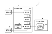
- the driving support system 1 includes a driving support device 2, a photographing device 3, a data storage device 4, and a warning device 5.
- the imaging device 3 is disposed in the vicinity of the driver B in the vehicle A and images the driver B's forward view.
- the photographing device 3 photographs a front landscape of the vehicle A that can be seen by the driver B through the front window of the vehicle A as the front view of the driver B.
- the arrangement position of the photographing device 3 does not necessarily have to be over the head of the driver B, and may be any position where the front window can be photographed.
- a plurality of photographing devices 3 may be used for photographing the field of view of the driver B.
- the photographing device 3 is connected to the driving support device 2.
- the driving support device 2 is connected to a data storage device 4 and a warning device 5.
- a wired cable may be used or wireless communication may be used.
- the driving support device 2 determines whether or not the driver B has overlooked an obstacle appearing in the field of view of the driver B, using the video information and the reaction time distribution data captured by the imaging device 3.
- the warning device 5 is a device that executes warning processing for the driver B. For example, the warning device 5 performs a voice or a display for alerting the driver B to the obstacle.
- the data storage device 4 stores the reaction time distribution data of the driver B.
- the reaction time distribution data is used for the determination by the driving support device 2.
- the reaction time distribution data is data indicating the distribution of the reaction time information of the driver B in the video in which the field of view of the driver B is captured.
- the reaction time information is information on the reaction time until the driver B reacts to the object that appears in the field of view of the driver B.
- the reaction time information includes, for example, the time range of the reaction time such as “I was able to react within less than 10 milliseconds”, “I was able to react within 100 milliseconds”, and “I was unable to react within 100 milliseconds”. It is.
- the reaction time distribution data is created before the driver B uses the driving support system 1.
- the driving support device 2 projects a certain mark on the fixed position of the front window in a state where the driver B is seated on the driver's seat.
- the mark indicates the position where the driver B is gazing before the bright spot is projected on the front window in the process of creating the reaction time distribution data.
- the driving support device 2 projects a bright spot on a random position on the front window while the driver B is gazing at the mark, and repeats the process of deleting the bright spot after a certain period of time (for example, 1 second).
- the head-up display mounted on the vehicle or the head-mounted display mounted on the driver B is used for the projection of the mark and the bright spot.
- the entire front window is within the view of the driver B.
- the image of the front window imaged by the imaging device 3 corresponds to an image in which the field of view of the driver B is imaged.
- a button switch mounted on the vehicle is connected to the driving support device 2.
- the driver B presses the button switch when moving the line of sight from the mark and viewing the bright spot.
- the button switch notifies the driving support device 2 that the driver B has pressed the button switch.
- the driving support device 2 calculates the time from when the bright switch is projected on the front window until the button switch is pressed by the driver B. This time is regarded as a reaction time until the driver B reacts to the object appearing at the position where the bright spot is projected.
- the driving support device 2 repeatedly executes projection and deletion of bright spots at random positions on the front window (for example, 100 times), and acquires the reaction time of the driver B corresponding to a plurality of positions on the front window. Subsequently, the driving support device 2 classifies the reaction time of the driver B acquired by the above-described repetition process into each of a plurality of divided regions obtained by dividing the image of the front window into a mesh shape, and the time range of the reaction time Is set for each divided area. Data indicating the time range of the reaction time set for each divided region is reaction time distribution data.
- operator B for every state of the driver
- reaction time distribution data created when driver B is naked reaction time distribution data created when driver B wears glasses, and created when driver B wears sunglasses
- Each of the reaction time distribution data may be stored in the data storage device 4 as independent data.
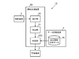
- FIG. 2 is a block diagram showing a configuration of the driving support system 1 according to the first embodiment.
- the driving support device 2 appears in the field of view of the driver B based on the video in which the field of view of the driver B is photographed by the photographing device 3 and the response time distribution data of the driver B stored in the data storage device 4. It is determined whether or not the driver B has overlooked the obstacle.
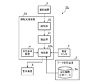
- the driving support device 2 includes an identification unit 20, an extraction unit 21, and a determination unit 22.
- the identification unit 20 identifies image elements in the video in which the field of view of the driver B is captured by the imaging device 3.
- the extraction unit 21 extracts the image element of the obstacle in the video from the image elements identified by the identification unit 20.
- the determination unit 22 specifies reaction time information corresponding to the position of the image element of the obstacle extracted by the extraction unit 21 using the reaction time distribution data 4a of the driver B stored in the data storage device 4. .
- the determination unit 22 determines whether or not the driver B has overlooked the obstacle based on the reaction time information corresponding to the position of the image element of the obstacle. For example, the determination unit 22 determines that the driver B has missed the obstacle when the reaction time information corresponding to the position of the image element of the obstacle exceeds the determination reference time a.
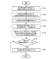
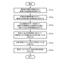
- FIG. 3 is a flowchart showing the operation of the driving support device 2.
- the identification unit 20 identifies image elements in the video in which the field of view of the driver B is captured by the imaging device 3 (step ST1). As described above, the field of view of the driver B is the scenery in front of the vehicle A through the front window.
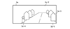
- FIG. 4 is a diagram illustrating an example of an image 3a in which the field of view of the driver B is captured. In the example shown in FIG. 4, the road 3a-1, the background 3a-2, the building 3a-3, and the pedestrian 3a-4 are shown in the video 3a in which the field of view of the driver B is captured. These are the identification objects of the image element.
- the identification unit 20 performs image analysis on the video 3a, and identifies the image elements of the road 3a-1, the background 3a-2, the building 3a-3, and the pedestrian 3a-4 from the video 3a.
- Information about the image element identified by the identification unit 20 is output to the extraction unit 21.
- the information about the image element is information including the type of the image element such as a road, background, building, and pedestrian and the position of the image element in the video 3a.
- the identification target object of the image element is not limited to that shown in FIG. 4.
- the pixel element of the falling object on the road may be identified.
- a pixel element having attached information that is a combination of the classification object type “road” and the position information of the falling object is identified.
- the extraction unit 21 extracts the image element of the obstacle in the video 3a from the image elements identified from the video 3a by the identification unit 20 (step ST2).
- the extraction unit 21 refers to an obstacle determination table set in advance, and extracts the image element of the obstacle in the video 3a from the image element identified by the identification unit 20.
- FIG. 5 is a diagram illustrating an example of the obstacle determination table. As shown in FIG. 5, in the obstacle determination table, the types of objects that can be obstacles of the vehicle A are registered. The image elements whose types are “pedestrian” and “bicycle” are determined to be obstacles by the extraction unit 21 from the obstacle determination table shown in FIG. The extraction unit 21 outputs information about the image element determined to be an obstacle and the video 3 a to the determination unit 22.
- the determination unit 22 uses the reaction time distribution data of the driver B stored in the data storage device 4 to respond to the position of the image element of the obstacle in the video 3a extracted by the extraction unit 21.
- Time information is specified (step ST3).
- the determination unit 22 identifies the reaction time information corresponding to the position of the image element of the obstacle by superimposing the video 3a including only the image element of the obstacle and the reaction time distribution data of the driver B.
- FIG. 6 is a diagram illustrating an example of the video 3a from which image elements other than the image elements of the obstacle are removed.
- the determination unit 22 leaves only the image elements of the pedestrian 3a-4 determined as an obstacle by the extraction unit 21 from the video 3a, and removes other image elements. As a result, an image 3a shown in FIG. 6 is obtained.
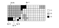
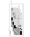
- FIG. 7 is a diagram showing an example of the reaction time distribution data 4a of the driver B.
- the reaction time distribution data 4a shown in FIG. 7 is a rectangular image in which the field of view of the driver B surrounded by the front window frame is 20 sections wide and 9 sections vertical in the image of the front window within the view of the driver B.
- the time range of the reaction time of the driver B is set for each divided region.
- the time range of the reaction time of the driver B is classified into three categories (1) to (3).
- the time range (1) set in the white divided area indicates that the reaction time of the driver B is less than 10 milliseconds.
- the time range (2) set in the gray divided area indicates that the reaction time of the driver B is 10 milliseconds or more and less than 300 milliseconds.
- the time range (3) set in the black divided area indicates that the driver B cannot react in less than 300 milliseconds.
- the driver B cannot react with the object or the reaction takes a long time.
- the time range of the reaction time is classified into three categories, but it may be classified into two categories, or may be classified into four or more categories.
- the divided area is a rectangle has been shown, it may be a polygon such as a hexagon or a circle.
- the number of divisions may be other than this.
- FIG. 8 is a diagram showing an image obtained by superimposing the image 3a in FIG. 6 and the reaction time distribution data 4a in FIG.
- the determination unit 22 superimposes the video 3a shown in FIG. 6 and the reaction time distribution data 4a shown in FIG. 7 to obtain reaction time information corresponding to the position of the image element of the pedestrian 3a-4 that is an obstacle. Identify.
- the image element of the pedestrian 3a-4 is at a position in an area 4a-2 composed of a black mesh area.
- the determination unit 22 obtains reaction time information indicating that “the driver B cannot react in less than 300 milliseconds” for the image element of the pedestrian 3a-4.
- the determination unit 22 determines whether or not the driver B has overlooked an obstacle (pedestrian 3a-4) based on the comparison result between the reaction time information obtained in step ST3 and the predetermined determination reference time a. Determine (step ST4).
- the determination unit 22 ends the process of FIG. While the vehicle A is traveling, a series of processes shown in FIG. 3 are periodically executed.
- the driver B recognizes the obstacle and takes some reaction It is expected that the reaction time required for the occurrence of the reaction is longer than that at other positions. Since the pedestrian 3a-4 exists in the area 4a-2, the reaction time information corresponding to the pedestrian 3a-4 is information indicating that the driver B cannot respond in less than 300 milliseconds.
- the determination unit 22 compares the reaction time information with the determination reference time a, so that the driver B can respond to the pedestrian 3a-4 within the determination reference time a. It is assumed that some kind of reaction cannot occur. Thereby, the determination part 22 determines with the driver B having overlooked the pedestrian 3a-4 (step ST4; YES).
- the determination unit 22 outputs warning information indicating that the driver B has overlooked the pedestrian 3a-4 to the warning device 5, and executes warning processing for the pedestrian 3a-4.
- the warning device 5 performs warning processing of the pedestrian 3a-4 on the driver B according to the instruction from the determination unit 22 (step ST5). For example, the warning device 5 performs a voice or a display for alerting the pedestrian 3a-4 to the driver B.
- the driving support apparatus 2 specifies the reaction time information corresponding to the position of the image element of the obstacle using the reaction time distribution data of the driver B, and the specified reaction time information. Based on the above, it is determined whether or not the driver B has overlooked the obstacle. Since the reaction time distribution data of the driver B shows the distribution of the reaction time information until the driver B reacts to the object appearing in the field of view of the driver B, the driver assistance device 2 It is possible to accurately determine whether or not an obstacle is overlooked.
- the driving support system 1 includes the components shown in FIG. 1, and when the determination unit 22 determines that the driver B has overlooked an obstacle, the warning device performs an obstacle warning process. 5 is executed. In the driving support system 1, it is accurately determined whether or not the driver B has overlooked the obstacle by the driving support device 2, and warning processing can be performed at an appropriate timing to call attention to the obstacle.
- the reaction time distribution data of the driver B is used as shown in FIG. 3, it is accurately determined whether or not the driver B has overlooked the obstacle, and the obstacle is obstructed.
- the warning process can be performed at an appropriate timing to call attention.
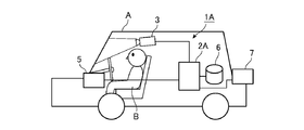
- FIG. FIG. 9 is a diagram showing an example of an arrangement in the vehicle A of the driving support system 1A according to Embodiment 2 of the present invention.
- the driving support system 1A is a system mounted on the vehicle A, and determines whether or not the driver B has overlooked an obstacle appearing in the driver B's field of view, and the driver B has overlooked the obstacle. In such a case, a warning process for alerting the driver B to the obstacle is executed.
- the driving support system 1A includes a driving support device 2A, a photographing device 3, a warning device 5, a data storage device 6, and an illuminance sensor 7.
- the data storage device 6 stores a plurality of reaction time distribution data associated with illuminance information.
- Illuminance information is information indicating the illuminance around the vehicle A when the reaction time distribution data is created.
- the reaction time distribution data is data indicating a distribution of the reaction time information of the driver B in an image in which the field of view of the driver B is captured.
- the illuminance sensor 7 is a sensor that detects the illuminance around the vehicle A. Illuminance information detected by the illuminance sensor 7 is output to the driving support device 2A.
- the driving support device 2 ⁇ / b> A appears in the visual field of the driver B using the video information obtained by photographing the visual field of the driver B by the photographing device 3 and the reaction time distribution data corresponding to the illuminance information detected by the illuminance sensor 7. It is determined whether or not the driver B has overlooked the obstacle.
- FIG. 10 is a block diagram showing the configuration of the driving support system 1A according to the second embodiment.
- the driving support device 2A includes an identification unit 20, an extraction unit 21, and a determination unit 22A.
- the determination unit 22 ⁇ / b> A is connected to the data storage device 6 and the illuminance sensor 7. For these connections, a wired cable may be used or wireless communication may be used.
- the determination unit 22A obtains reaction time distribution data corresponding to illuminance information detected by the illuminance sensor 7 from a plurality of reaction time distribution data constituting the reaction time distribution data 6a stored in the data storage device 6. select. For example, the determination unit 22A corresponds to the illuminance closest to the illuminance detected by the illuminance sensor 7 from the plurality of reaction time distribution data stored in the data storage device 6 and each associated with the illuminance information. Select the attached reaction time distribution data.
- the determination unit 22A specifies reaction time information corresponding to the position of the image element of the obstacle extracted by the extraction unit 21 using the reaction time distribution data 6a selected as described above, and uses the specified reaction time information. Based on this, it is determined whether or not the driver B has overlooked the obstacle. For example, the determination unit 22 determines that the driver B has missed the obstacle when the reaction time information corresponding to the position of the image element of the obstacle exceeds the determination reference time a.
- FIG. 11 is a diagram showing an example of the reaction time distribution data 6a in the second embodiment.
- the data storage device 6 stores the reaction time distribution data 6a of the driver B.
- the reaction time distribution data 6a is composed of a plurality of reaction time distribution data including reaction time distribution data 6a-1, reaction time distribution data 6a-2, and reaction time distribution data 6a-3. .
- the reaction time distribution data 6a-1, the reaction time distribution data 6a-2, and the reaction time distribution data 6a-3 are associated with illuminance information indicating the illuminance when these are created.
- FIG. 12 is a flowchart showing the operation of the driving support apparatus 2A. Note that the processing from step ST1a to step ST2a shown in FIG. 12 is the same as the processing from step ST1 to step ST2 shown in FIG. The process from step ST6a to step ST7a shown in FIG. 12 is the same as the process from step ST4 to step ST5 shown in FIG. Description of these processes is omitted.
- the determination unit 22A acquires illuminance information around the vehicle A detected by the illuminance sensor 7 (step ST3a). For example, the illuminance sensor 7 detects illuminance information in front of the vehicle A, and the illuminance information is acquired by the determination unit 22A. Next, the determination unit 22A selects the reaction time distribution data 6a corresponding to the illuminance information detected by the illuminance sensor 7 from the plurality of reaction time distribution data 6a stored in the data storage device 6 (step ST4a). ).
- the determination unit 22A specifies reaction time information corresponding to the position of the image element of the obstacle in the video 3a extracted by the extraction unit 21 using the reaction time distribution data 6a selected in step ST4a (step ST5a). .
- the determination unit 22A identifies the reaction time information corresponding to the position of the obstacle image element by superimposing the video 3a including only the obstacle image element and the reaction time distribution data 6a of the driver B.
- the subsequent processing is the same as in FIG.
- the determination unit 22A corresponds to the illuminance information around the vehicle A from the plurality of reaction time distribution data 6a associated with the illuminance information.
- Reaction time distribution data 6a is selected.
- Human visual sensitivity varies depending on the ambient illumination. For example, the visual sensitivity near the center of the field of view in the daytime is high, but the visual sensitivity near the center of the field of view may decrease in a dark place.
- the driving support device 2A selects the reaction time distribution data 6a corresponding to the illuminance information around the vehicle A, thereby determining whether or not the driver B has overlooked the obstacle according to the illuminance. Reflects fluctuations in sensitivity. Thereby, in the driving assistance apparatus 2A, it is possible to accurately determine whether or not the driver B has overlooked an obstacle.
- reaction time distribution data is prepared for each illuminance information.
- reaction time distribution data may be prepared for each type of background image texture.
- the human visual sensitivity varies depending on the background image texture type (for example, the type of texture constituting the image of the object and the feature) of the obstacle (such as the pedestrian 3a-4) in the video 3a shown in FIG. . Therefore, reaction time distribution data is prepared for each type of background image texture, and the determination unit 22A selects the background image texture type in the current video 3a from the reaction time distribution data for each type of background image texture. Corresponding reaction time distribution data may be selected. Also in this case, it is possible to accurately determine whether or not the driver B has overlooked the obstacle.
- FIG. 13 is a block diagram showing a configuration of a driving support system 1B according to Embodiment 3 of the present invention.
- the driving support system 1B determines whether or not the driver B has overlooked an obstacle that has appeared in the field of view of the driver B, and the driver B detects the obstacle. When overlooked, a warning process for alerting the driver B to the obstacle is executed.
- the driving support system 1B includes a driving support device 2B, a photographing device 3, a data storage device 4, and a warning device 5.
- the driving support device 2B includes an identification unit 20, an extraction unit 21, a determination unit 22, and a data acquisition unit 23.
- the data acquisition unit 23 acquires the reaction time distribution data from the external storage device 8 holding the reaction time distribution data.
- the external storage device 8 may be a storage medium such as an SD card, but may be a storage device capable of communication connection with the driving support device 2B.
- the data acquisition unit 23 acquires reaction time distribution data from the storage medium using a reading device (not shown) provided in the driving support device 2B.
- the data acquisition unit 23 communicates with the storage device using a communication device (not shown) provided in the driving support device 2B, and reacts from the storage device. Get time distribution data.
- FIG. 13 shows a configuration in which the data acquisition unit 23 is added to the driving support device 2 according to the first embodiment.
- the data acquisition unit 23 is added to the driving support device 2A according to the second embodiment. May be.
- the data acquisition unit 23 responds to the illuminance around the vehicle A detected by the illuminance sensor 7. Distribution data is acquired from the storage medium and output to the determination unit 22A.
- the driving assistance apparatus 2B includes the data acquisition unit 23 that acquires reaction time distribution data from an external apparatus.
- the driving assistance device 2B can use reaction time distribution data created previously.
- the data acquisition unit 23 acquires the reaction time distribution data from the data storage device 4 in which the reaction time distribution data created by the vehicle before the change is stored. Thereby, in the driving assistance apparatus 2B, it is not necessary to create reaction time distribution data again with the vehicle after changing.
- FIG. 14 is a block diagram showing a configuration of a driving support system 1C according to Embodiment 4 of the present invention.
- the driving support system 1C determines whether or not the driver B has overlooked an obstacle that has appeared in the field of view of the driver B, and the driver B detects the obstacle. When overlooked, a warning process for alerting the driver B to the obstacle is executed.
- the driving support system 1C includes a driving support device 2C, a photographing device 3, a warning device 5, and a data storage device 9, as shown in FIG.
- the data storage device 9 stores the reaction time distribution data 9a and the date (data creation date) when the reaction time distribution data 9a is created in association with each other.
- the driving support device 2C includes an identification unit 20, an extraction unit 21, and a determination unit 22B.
- the determination unit 22B uses the reaction time distribution data 9a of the driver B stored in the data storage device 9 to determine the position of the obstacle image element extracted by the extraction unit 21. Identify the corresponding reaction time information. The determination unit 22B determines that the driver B has missed the obstacle when the reaction time information corresponding to the position of the image element of the obstacle exceeds the determination reference time a.
- the determination unit 22B warns a process for prompting the driver B to recreate the reaction time distribution data 9a when the elapsed time from the creation of the reaction time distribution data 9a exceeds the recreation reference period b. 5 is executed. For example, when the re-creation reference period b is 1 year and the elapsed period from the creation of the reaction time distribution data 9a exceeds 1 year, the determination unit 22B prompts the re-creation of the reaction time distribution data 9a. Is executed by the warning device 5.
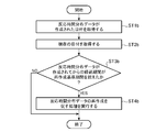
- FIG. 15 is a flowchart showing the operation of the driving support apparatus 2C according to the fourth embodiment, and shows a series of processes related to the update of the reaction time distribution data 9a.
- the determination unit 22B obtains the date on which the reaction time distribution data 9a is created that is associated with the reaction time distribution data 9a stored in the data storage device 9 (step ST1b). Subsequently, the determination unit 22B acquires the current date (step ST2b).
- the current date may be acquired from a timer built in the driving support device 2C, or may be acquired from an external device via a communication network.
- the driver B may manually set the date for the determination unit 22B.
- the determination unit 22B calculates the elapsed time since the reaction time distribution data 9a was created from the date when the reaction time distribution data 9a was created and the current date, and the elapsed time exceeds the re-creation reference period b. It is confirmed whether or not (step ST3b).
- the determination unit 22B ends the process of FIG. Note that the series of processing illustrated in FIG. 15 is periodically executed by the determination unit 22B.
- the determination unit 22B uses the warning device 5 to execute processing for prompting the driver B to re-create the reaction time distribution data 9a.
- Step ST4b For example, when the re-creation reference period b is one year, the determination unit 22B notifies the warning device 5 that one year has passed since the reaction time distribution data 9a was created.
- the warning device 5 receives the notification from the determination unit 22B, the warning device 5 performs a voice or display requesting the driver B to update the reaction time distribution data 9a.
- the re-creation reference period b is 1 year, this is an example, and it may be a period shorter than 1 year or a period longer than 1 year.
- the determination unit 22B determines that the driver B when the elapsed period from the generation of the reaction time distribution data 9a exceeds the re-creation reference period b. Then, the warning device 5 is caused to execute processing for prompting the recreation of the reaction time distribution data 9a.
- the driver B re-creates the reaction time distribution data 9a in response to a request from the driving support device 2C, so that the difference between the reaction time distribution data 9a and the visual response speed of the driver B is suppressed, and the driver It is possible to accurately determine whether B has overlooked an obstacle.
- FIG. 16 is a block diagram showing a configuration of a driving support system 1D according to Embodiment 5 of the present invention.
- the driving support system 1D determines the response time level of the driver B with respect to the obstacle appearing in the field of view of the driver B, and executes warning processing having different contents depending on the response time level.
- the driving support system 1D includes a driving support device 2D, a photographing device 3, a data storage device 4, and a warning device 5, as shown in FIG.
- the driving support device 2D includes an identification unit 20, an extraction unit 21, and a determination unit 22C.
- the determination unit 22C determines the reaction time level of the driver B with respect to the obstacle based on the reaction time information corresponding to the position of the image element of the obstacle in the video 3a, and warnings having different contents depending on the reaction time level. The processing is executed by the warning device 5.
- a warning level corresponding to the reaction time level is set in the determination unit 22C.
- the reaction time level becomes higher as the reaction time becomes shorter, and becomes lower as the reaction time becomes longer.
- the warning level is lower as the reaction time level is higher, and is higher as the reaction time level is lower.
- the content of the obstacle warning process varies depending on the warning level.
- the reaction time level may be directly associated with the content of the warning process without providing the warning level.
- FIG. 17 is a flowchart showing the operation of the driving support device 2D. Note that the processing from step ST1c to step ST3c shown in FIG. 17 is the same as the processing from step ST1 to step ST3 shown in FIG. 3, so description of these processing will be omitted.
- the determination unit 22C determines the reaction time level of the driver B for the obstacle based on the reaction time information specified in step ST3c (step ST4c).
- the determination unit 22C when the reaction time information corresponding to the position of the image element of the obstacle in the video 3a indicates that the reaction time of the driver B is less than 10 milliseconds, the determination unit 22C has a high reaction time level. Judged to be level. When the reaction time information indicates that the reaction time of the driver B is 10 milliseconds or more and less than 300 milliseconds, the determination unit 22C determines that the reaction time level is a medium level. When the reaction time information indicates that the driver B cannot react in less than 300 milliseconds, the determination unit 22C determines that the reaction time level is low.
- the determination unit 22C specifies a warning level corresponding to the reaction time level (step ST5c). For example, when the reaction time level is high, the determination unit 22C sets the warning level for the obstacle to a low level, and when the reaction time level is medium, the determination unit 22C sets the warning level for the obstacle to medium. Level. Furthermore, when the reaction time level is low, the determination unit 22C sets the warning level for the obstacle to a high level.
- the determination unit 22C uses the warning device 5 to execute a warning process with content corresponding to the warning level (step ST6c). For example, when the warning level is low, the warning device 5 outputs a buzzer sound for notifying the presence of an obstacle. When the warning level is the medium level, the warning device 5 outputs the buzzer sound at a volume larger than the low level. When the warning level is high, the warning device 5 outputs the buzzer sound at the maximum volume.
- the determination unit 22C may cause the warning device 5 to output different character information for each warning level corresponding to the reaction time level. For example, if the reaction time level is high (warning level low), the warning device 5 displays character information notifying the presence of an obstacle such as “there is a pedestrian”. If the reaction time level is medium (warning level), the warning device 5 displays character information for calling attention to an obstacle such as “Please watch out for pedestrian behavior”. Furthermore, when the reaction time level is low (warning level high), the warning device 5 displays character information that warns of avoidance of an obstacle such as “There is a possibility of touching a pedestrian”.
- the display color according to the warning level may be used for displaying the warning information by the warning device 5. For example, red for warning, yellow for attention, and blue for simple notification may be used depending on the warning level.
- the determination unit 22C may instruct the vehicle control device to automatically brake the vehicle A.
- the driving support device 2D includes the identification unit 20, the extraction unit 21, and the determination unit 22C.
- the determination unit 22C determines the response time level of the driver B with respect to the obstacle based on the reaction time information corresponding to the position of the image element of the obstacle, and performs warning processing with different contents depending on the reaction time level. 5 is executed.
- warning processing having different contents is executed according to the reaction time level of the driver B with respect to the obstacle, so that an effective warning can be given to the driver B.
- the driving support apparatus includes a processing circuit for executing the processing of each step in the flowcharts described so far.
- the processing circuit may be dedicated hardware or a CPU (Central Processing Unit) that executes a program stored in the memory.
- FIG. 18A is a block diagram showing a hardware configuration for realizing the function of the driving support apparatus according to any one of the first to fifth embodiments.
- FIG. 18B is a block diagram illustrating a hardware configuration that executes software that implements the functions of the driving support apparatus according to any one of Embodiments 1 to 5.
- the camera 100 is the imaging device 3 shown in the first to fifth embodiments.
- the speaker 101 and the display 102 are devices that implement the warning device 5 described in the first to fifth embodiments.
- the speaker 101 is a speaker mounted on the vehicle A
- the display 102 is a display included in an electronic device mounted on the vehicle A.
- the storage device 103 is a storage device that realizes one of the data storage devices 4, 6, and 9 shown in the first to fifth embodiments.
- the storage device 103 may be a storage device included in the driving support device, or may be a storage device provided independently of the driving support device. These storage devices may be storage devices provided so as to be communicable from the driving support device, for example, storage devices existing on the cloud.
- the processing circuit 104 may be, for example, a single circuit, a composite circuit, a programmed processor, a parallel programmed processor, an ASIC (Application Specific Integrated Circuit), or the like. ), FPGA (Field-Programmable Gate Array), or a combination thereof.
- the functions of the components in the driving support devices 2 and 2A to 2D may be realized by separate processing circuits, or these functions may be realized by a single processing circuit.
- the processing circuit is the processor 105 shown in FIG. 18B
- the functions of the components in the driving support devices 2, 2A to 2D are realized by software, firmware, or a combination of software and firmware.
- the software or firmware is described as a program and stored in the memory 106.
- the processor 105 reads out and executes the program stored in the memory 106, thereby realizing the functions of the components in the driving support devices 2, 2A to 2D.
- the driving support devices 2, 2A to 2D include a memory 106 for storing a program that, when executed by the processor 105, results in the processing of each step in the flowcharts described so far. These programs cause a computer to execute the procedure or method of each component in the driving support devices 2, 2A to 2D.
- the memory 106 may be a computer-readable storage medium storing a program for causing a computer to function as each component in the driving support apparatuses 2 and 2A to 2D.
- the memory 106 is, for example, a nonvolatile memory such as a RAM (Random Access Memory), a ROM (Read Only Memory), a flash memory, an EPROM (Erasable Programmable Read Only Memory), an EEPROM (Electrically-EPROM), or a volatile memory such as an EEPROM (Electrically-EPROM).
- a nonvolatile memory such as a RAM (Random Access Memory), a ROM (Read Only Memory), a flash memory, an EPROM (Erasable Programmable Read Only Memory), an EEPROM (Electrically-EPROM), or a volatile memory such as an EEPROM (Electrically-EPROM).
- a disk, a flexible disk, an optical disk, a compact disk, a mini disk, a DVD, and the like are applicable.
- Part of the functions of the components in the driving support devices 2 and 2A to 2D may be realized by dedicated hardware, and part of the functions may be realized by software or firmware.
- the identification unit 20 and the extraction unit 21 realize the function by the processing circuit 104 that is dedicated hardware, and the determination units 22 and 22A to 22C read and execute the program stored in the memory 106 by the processor 105. To realize the function.
- the processing circuit can realize the above functions by hardware, software, firmware, or a combination thereof.
- the driving support device can accurately determine whether or not the driver has overlooked an obstacle, and thus has wide applicability in the field of vehicle safety technology.
Landscapes
- Physics & Mathematics (AREA)
- General Physics & Mathematics (AREA)
- Traffic Control Systems (AREA)
- Image Analysis (AREA)
Abstract
運転支援装置(2)は、運転者の視界が撮影された映像(3a)内における、運転者の視界に現れた物体に対して運転者が反応を起こすまでの反応時間情報の分布を示す反応時間分布データ(4a)を用いて障害物の画像要素の位置に対応する反応時間情報を特定し、特定した反応時間情報に基づいて運転者が障害物を見落としているか否かを判定する。
Description
この発明は、車両の運転者が障害物を見落としているか否かを判定する運転支援装置に関する。
例えば、特許文献1に記載された装置は、障害物情報、運転者の視線が向いている方向および運転者の視野範囲に基づいて、運転者が障害物を見落としているか否かを判定している。
実際には、運転者の視線が向いている方向に対象物が存在する場合であっても、運転者が直ちに反応できる程度に対象物を認知しているとは限らない。
このため、特許文献1に記載された装置では、運転者が障害物を見落としているか否かを正確に判定できないという課題があった。
このため、特許文献1に記載された装置では、運転者が障害物を見落としているか否かを正確に判定できないという課題があった。
この発明は上記課題を解決するものであり、運転者が障害物を見落としているか否かを正確に判定できる運転支援装置を得ることを目的とする。
この発明に係る運転支援装置は、識別部、抽出部および判定部を備える。識別部は、車両の運転者の視界が撮影された映像内の画像要素を識別する。抽出部は、識別部によって識別された画像要素の中から映像内の障害物の画像要素を抽出する。判定部は、運転者の視界に現れた物体に対して運転者が反応を起こすまでの反応時間情報の映像内での分布を示す反応時間分布データを用いて、抽出部によって抽出された障害物の画像要素の位置に対応する反応時間情報を特定し、特定した反応時間情報に基づいて運転者が障害物を見落としているか否かを判定する。
この発明によれば、運転支援装置は、運転者の視界が撮影された映像内における、運転者の視界に現れた物体に対して運転者が反応を起こすまでの反応時間情報の分布を示す反応時間分布データを用いて障害物の画像要素の位置に対応する反応時間情報を特定し、特定した反応時間情報に基づいて運転者が障害物を見落としているか否かを判定する。これにより、運転支援装置は、運転者が障害物を見落としているか否かを正確に判定できる。
以下、この発明をより詳細に説明するため、この発明を実施するための形態について、添付の図面に従って説明する。
実施の形態1.
図1は、この発明の実施の形態1に係る運転支援システム1の車両A内における配置の一例を示す図である。運転支援システム1は、車両Aに搭載されたシステムであり、運転者Bの視界に現れた障害物を運転者Bが見落としているか否かを判定し、運転者Bが障害物を見落としている場合に、運転者Bに対して障害物への注意を喚起する警告処理を実行する。図1において、運転支援システム1は、運転支援装置2、撮影装置3、データ記憶装置4および警告装置5を備える。
実施の形態1.
図1は、この発明の実施の形態1に係る運転支援システム1の車両A内における配置の一例を示す図である。運転支援システム1は、車両Aに搭載されたシステムであり、運転者Bの視界に現れた障害物を運転者Bが見落としているか否かを判定し、運転者Bが障害物を見落としている場合に、運転者Bに対して障害物への注意を喚起する警告処理を実行する。図1において、運転支援システム1は、運転支援装置2、撮影装置3、データ記憶装置4および警告装置5を備える。
撮影装置3は、車両A内で運転者Bの頭上付近に配置され、運転者Bの前方視界を撮影する。例えば、撮影装置3は、運転者Bの前方視界として、車両Aのフロントウィンドウを通して運転者Bが見ることができる車両Aの前方風景を撮影する。なお、撮影装置3の配置位置は、必ずしも運転者Bの頭上でなくてもよく、フロントウィンドウの撮影が可能な位置であればよい。運転者Bの視界の撮影には、複数の撮影装置3を用いてもよい。
撮影装置3は、運転支援装置2に接続されている。また、運転支援装置2には、撮影装置3のほかに、データ記憶装置4および警告装置5に接続されている。これらの装置間の接続には、有線ケーブルを用いてもよいし、無線通信を用いてもよい。
運転支援装置2は、撮影装置3によって撮影された映像情報および反応時間分布データを用いて、運転者Bの視界に現れた障害物を運転者Bが見落としているか否かを判定する。
また、警告装置5は、運転者Bに対する警告処理を実行する装置である。例えば、警告装置5は、運転者Bに対して障害物への注意を喚起する音声または表示を行う。
また、警告装置5は、運転者Bに対する警告処理を実行する装置である。例えば、警告装置5は、運転者Bに対して障害物への注意を喚起する音声または表示を行う。
データ記憶装置4には、運転者Bの反応時間分布データが記憶されている。反応時間分布データは、運転支援装置2による上記判定に使用される。なお、反応時間分布データは、運転者Bの視界が撮影された映像内における運転者Bの反応時間情報の分布を示すデータである。反応時間情報は、運転者Bの視界に現れた物体に対して運転者Bが反応を起こすまでの反応時間に関する情報である。反応時間に関する情報には、例えば、“10ミリ秒未満で反応できた”、“100ミリ秒以内に反応できた”、“100ミリ秒以内に反応できなかった”といった反応時間の時間範囲が含まれる。
反応時間分布データは、運転者Bが運転支援システム1を利用する前段階で作成される。例えば、運転支援装置2は、運転者Bが運転席に着座した状態で、フロントウィンドウの固定位置に一定のマークを投影する。マークは、反応時間分布データの作成処理において、フロントウィンドウに輝点が投影されるまでに、運転者Bが注視する位置を示している。運転支援装置2は、運転者Bがマークを注視した状態で、フロントウィンドウのランダムな位置に輝点を投影し、一定時間(例えば、1秒間)が経過すると輝点を消去する処理を繰り返す。
マークおよび輝点の投影には、車両に搭載されたヘッドアップディスプレイまたは運転者Bに装着されたヘッドマウントディスプレイが利用される。なお、運転者Bが運転席に着座した状態では、フロントウィンドウの全体が運転者Bの視界に収まる。これにより、撮影装置3によって撮影されたフロントウィンドウの映像は、運転者Bの視界が撮影された映像に相当する。
また、運転支援装置2には、車両に搭載されたボタンスイッチが接続されている。反応時間分布データの作成において、運転者Bは、マークから視線を移動させて輝点を見たときにボタンスイッチを押下する。ボタンスイッチは、運転者Bによる押下を運転支援装置2に通知する。この通知を受けると、運転支援装置2は、フロントウィンドウに輝点を投影してから運転者Bによってボタンスイッチが押下されるまでの時間を算出する。この時間が、輝点が投影された位置に現れた物体に対して運転者Bが反応を起こすまでの反応時間とみなされる。
運転支援装置2は、フロントウィンドウのランダムな位置に輝点の投影と消去とを繰り返し実行し(例えば、100回)、フロントウィンドウの複数の位置に対応する運転者Bの反応時間を取得する。続いて、運転支援装置2は、前述した繰り返し処理で取得された運転者Bの反応時間を、フロントウィンドウの映像をメッシュ状に分割した複数の分割領域の各々に分類し、反応時間の時間範囲を分割領域ごとに設定する。このように分割領域ごとに設定された反応時間の時間範囲を示すデータが反応時間分布データである。
なお、運転者Bに関する反応時間分布データは、反応時間分布データを作成したときの運転者Bの状態ごとに設けてもよい。例えば、運転者Bが裸眼であるときに作成された反応時間分布データ、運転者Bが眼鏡を掛けたときに作成された反応時間分布データおよび運転者Bがサングラスを掛けたときに作成された反応時間分布データのそれぞれを独立したデータとしてデータ記憶装置4に記憶してもよい。
図2は、実施の形態1に係る運転支援システム1の構成を示すブロック図である。運転支援装置2は、撮影装置3によって運転者Bの視界が撮影された映像とデータ記憶装置4に記憶された運転者Bの反応時間分布データとに基づいて、運転者Bの視界に現れた障害物を運転者Bが見落としているか否かを判定する。運転支援装置2は、図2に示すように、識別部20、抽出部21および判定部22を備える。識別部20は、撮影装置3によって運転者Bの視界が撮影された映像内の画像要素を識別する。抽出部21は、識別部20によって識別された画像要素の中から映像内の障害物の画像要素を抽出する。
判定部22は、データ記憶装置4に記憶されている運転者Bの反応時間分布データ4aを用いて、抽出部21によって抽出された障害物の画像要素の位置に対応する反応時間情報を特定する。判定部22は、障害物の画像要素の位置に対応する反応時間情報に基づいて運転者Bが障害物を見落としているか否かを判定する。例えば、判定部22は、障害物の画像要素の位置に対応する反応時間情報が判定基準時間aを超える場合に、運転者Bが障害物を見落としていると判定する。
次に動作について説明する。
図3は、運転支援装置2の動作を示すフローチャートである。
識別部20は、撮影装置3によって運転者Bの視界が撮影された映像内の画像要素を識別する(ステップST1)。前述したように、運転者Bの視界とは、フロントウィンドウを通した車両Aの前方風景である。図4は、運転者Bの視界が撮影された映像3aの一例を示す図である。図4に示す例では、運転者Bの視界が撮影された映像3aに、道路3a-1、背景3a-2、建造物3a-3および歩行者3a-4が写っている。これらが画像要素の識別対象物である。
図3は、運転支援装置2の動作を示すフローチャートである。
識別部20は、撮影装置3によって運転者Bの視界が撮影された映像内の画像要素を識別する(ステップST1)。前述したように、運転者Bの視界とは、フロントウィンドウを通した車両Aの前方風景である。図4は、運転者Bの視界が撮影された映像3aの一例を示す図である。図4に示す例では、運転者Bの視界が撮影された映像3aに、道路3a-1、背景3a-2、建造物3a-3および歩行者3a-4が写っている。これらが画像要素の識別対象物である。
識別部20は、映像3aを画像解析して、道路3a-1、背景3a-2、建造物3a-3および歩行者3a-4のそれぞれの画像要素を、映像3aから識別する。識別部20によって識別された画像要素に関する情報は、抽出部21に出力される。画像要素に関する情報は、道路、背景、建造物および歩行者などの画像要素の種別と画像要素の映像3a内での位置とを含む情報である。なお、画像要素の識別対象物は、図4に示したものに限定されるものではなく、例えば、道路上の落下物の画素要素を識別してもよい。この場合、識別対象物の種別“道路”と落下物の位置情報との組み合わせた付属情報を有する画素要素が識別される。
次に、抽出部21は、識別部20によって映像3aから識別された画像要素の中から、映像3a内の障害物の画像要素を抽出する(ステップST2)。例えば、抽出部21は、予め設定された障害物判定表を参照して、識別部20によって識別された画像要素から、映像3a内の障害物の画像要素を抽出する。図5は障害物判定表の一例を示す図である。図5に示すように、障害物判定表には、車両Aの障害物となり得る物体の種別が登録されている。種別が“歩行者”および“自転車”である画像要素は、図5に示す障害物判定表から、抽出部21によって障害物であると判断される。抽出部21は、障害物と判断した画像要素に関する情報および映像3aを判定部22に出力する。
続いて、判定部22は、データ記憶装置4に記憶された運転者Bの反応時間分布データを用いて、抽出部21によって抽出された映像3a内の障害物の画像要素の位置に対応する反応時間情報を特定する(ステップST3)。例えば、判定部22は、障害物の画像要素のみを含む映像3aと運転者Bの反応時間分布データとを重ね合わせて、障害物の画像要素の位置に対応する反応時間情報を特定する。
図6は、障害物の画像要素以外の画像要素を除去した映像3aの一例を示す図である。判定部22は、映像3aから、抽出部21によって障害物と判断された歩行者3a-4の画像要素のみを残し、それ以外の画像要素を除去する。これによって図6に示す映像3aが得られる。
図7は、運転者Bの反応時間分布データ4aの一例を示す図である。図7に示す反応時間分布データ4aは、運転者Bの視界内にあるフロントウィンドウの映像において、フロントウィンドウ枠で囲まれた運転者Bの視界領域が、横20区画、縦9区画の矩形状の領域に分割されており、運転者Bの反応時間の時間範囲が分割領域ごとに設定されている。運転者Bの反応時間の時間範囲は、(1)~(3)の3つの区分に分類されている。
例えば、白色の分割領域に設定された時間範囲(1)は、運転者Bの反応時間が10ミリ秒未満であることを示している。灰色の分割領域に設定された時間範囲(2)は、運転者Bの反応時間が10ミリ秒以上300ミリ秒未満であることを示している。黒色の分割領域に設定された時間範囲(3)は、運転者Bが300ミリ秒未満で反応できないことを示している。黒色の分割領域で構成された領域4a-1、領域4a-2および領域4a-3では、運転者Bが物体を反応できないか、反応に長時間を要する。
なお、図7では反応時間の時間範囲を3つの区分に分類したが、2つの区分に分類してもよいし、4つ以上の区分に分類してもよい。また、分割領域が矩形である場合を示したが、六角形などの多角形であってもよいし、円形であってもよい。さらに、フロントウィンドウの映像を横20区画、縦9区画に分割した場合を示したが、分割数は、これ以外であってもよい。
図8は、図6の映像3aと図7の反応時間分布データ4aとを重ね合わせた映像を示す図である。判定部22は、図6に示した映像3aと図7に示した反応時間分布データ4aとを重ね合わせて、障害物である歩行者3a-4の画像要素の位置に対応する反応時間情報を特定する。図8において、歩行者3a-4の画像要素は、黒色のメッシュ領域で構成された領域4a-2内の位置にある。このとき、判定部22は、歩行者3a-4の画像要素について“運転者Bが300ミリ秒未満で反応できない”という内容の反応時間情報を取得する。
図3の説明に戻る。
判定部22は、ステップST3で得た反応時間情報と予め設定された判定基準時間aとの比較結果に基づいて、運転者Bが障害物(歩行者3a-4)を見落としているか否かを判定する(ステップST4)。ここで、運転者Bが歩行者3a-4を見落としていないと判定した場合(ステップST4;NO)、判定部22は、図3の処理を終了する。車両Aが走行している間、図3に示す一連の処理は周期的に実行される。
判定部22は、ステップST3で得た反応時間情報と予め設定された判定基準時間aとの比較結果に基づいて、運転者Bが障害物(歩行者3a-4)を見落としているか否かを判定する(ステップST4)。ここで、運転者Bが歩行者3a-4を見落としていないと判定した場合(ステップST4;NO)、判定部22は、図3の処理を終了する。車両Aが走行している間、図3に示す一連の処理は周期的に実行される。
例えば、図7に示した領域4a-1、領域4a-2および領域4a-3に対応する実際の位置に障害物が出現した場合に、運転者Bが、この障害物を認知して何らかの反応を起こすまでに要する反応時間は、他の位置に比べて長いことが予想される。歩行者3a-4は領域4a-2に存在するため、歩行者3a-4に対応する反応時間情報は、運転者Bが300ミリ秒未満で反応できないことを示す情報である。
判定基準時間aが300ミリ秒である場合、判定部22は、上記反応時間情報と判定基準時間aとを比較することで、運転者Bが判定基準時間a以内に歩行者3a-4に対して何らかの反応を起こせないとみなす。これにより、判定部22は、運転者Bが歩行者3a-4を見落としていると判定する(ステップST4;YES)。
次に、判定部22は、運転者Bが歩行者3a-4を見落としていることを示す警告情報を警告装置5に出力し、歩行者3a-4に対する警告処理を実行させる。警告装置5は、判定部22からの指示に従って、運転者Bに対して歩行者3a-4の警告処理を実行する(ステップST5)。例えば、警告装置5は、運転者Bに対して歩行者3a-4への注意を喚起する音声または表示を行う。
前述したように、実施の形態1に係る運転支援装置2は、運転者Bの反応時間分布データを用いて障害物の画像要素の位置に対応する反応時間情報を特定し、特定した反応時間情報に基づいて運転者Bが障害物を見落としているか否かを判定する。運転者Bの反応時間分布データは、運転者Bの視界に現れた物体に対して運転者Bが反応を起こすまでの反応時間情報の分布を示すので、運転支援装置2は、運転者Bが障害物を見落としているか否かを正確に判定することができる。
実施の形態1に係る運転支援システム1は、図1に示した構成要素を備え、判定部22が、運転者Bが障害物を見落としていると判定した場合、障害物の警告処理を警告装置5に実行させる。運転支援システム1では、運転支援装置2によって運転者Bが障害物を見落としているか否かが正確に判定され、障害物への注意を喚起すべき適切なタイミングで警告処理を行うことができる。
実施の形態1に係る運転支援方法では、図3に示すように運転者Bの反応時間分布データを用いるので、運転者Bが障害物を見落としているか否かが正確に判定され、障害物への注意を喚起すべき適切なタイミングで警告処理を行うことができる。
実施の形態2.
図9は、この発明の実施の形態2に係る運転支援システム1Aの車両A内における配置の一例を示す図である。図9において、図1と同一の構成要素には、同一の符号を付して説明を省略する。運転支援システム1Aは、車両Aに搭載されたシステムであり、運転者Bの視界に現れた障害物を運転者Bが見落としているか否かを判定し、運転者Bが障害物を見落としている場合に、運転者Bに対して障害物への注意を喚起する警告処理を実行する。運転支援システム1Aは、運転支援装置2A、撮影装置3、警告装置5、データ記憶装置6および照度センサ7を備える。
図9は、この発明の実施の形態2に係る運転支援システム1Aの車両A内における配置の一例を示す図である。図9において、図1と同一の構成要素には、同一の符号を付して説明を省略する。運転支援システム1Aは、車両Aに搭載されたシステムであり、運転者Bの視界に現れた障害物を運転者Bが見落としているか否かを判定し、運転者Bが障害物を見落としている場合に、運転者Bに対して障害物への注意を喚起する警告処理を実行する。運転支援システム1Aは、運転支援装置2A、撮影装置3、警告装置5、データ記憶装置6および照度センサ7を備える。
データ記憶装置6には、照度情報に対応付けられた複数の反応時間分布データが記憶されている。照度情報とは、反応時間分布データが作成されたときの車両Aの周辺の照度を示す情報である。反応時間分布データは、運転者Bの視界が撮影された映像内における運転者Bの反応時間情報の分布を示すデータである。照度センサ7は、車両Aの周辺の照度を検出するセンサである。照度センサ7によって検出された照度情報は運転支援装置2Aに出力される。運転支援装置2Aは、撮影装置3によって運転者Bの視界が撮影された映像情報と照度センサ7によって検出された照度情報に対応する反応時間分布データとを用いて、運転者Bの視界に現れた障害物を運転者Bが見落としているか否かを判定する。
図10は、実施の形態2に係る運転支援システム1Aの構成を示すブロック図である。図10において、図2と同一の構成要素には、同一の符号を付して説明を省略する。運転支援装置2Aは、識別部20、抽出部21および判定部22Aを備えて構成される。判定部22Aは、図10に示すように、データ記憶装置6および照度センサ7に接続されている。これらの接続には、有線ケーブルを用いてもよいし、無線通信を用いてもよい。
判定部22Aは、データ記憶装置6に記憶されている、反応時間分布データ6aを構成する複数の反応時間分布データのうちから、照度センサ7によって検出された照度情報に対応した反応時間分布データを選択する。例えば、判定部22Aは、データ記憶装置6に記憶されている、各々が照度情報に対応付けられた複数の反応時間分布データの中から、照度センサ7によって検出された照度に最も近い照度に対応付けられている反応時間分布データを選択する。
判定部22Aは、前述のように選択した反応時間分布データ6aを用いて、抽出部21によって抽出された障害物の画像要素の位置に対応する反応時間情報を特定し、特定した反応時間情報に基づいて運転者Bが障害物を見落としているか否かを判定する。例えば、判定部22は、障害物の画像要素の位置に対応する反応時間情報が判定基準時間aを超える場合、運転者Bが障害物を見落としていると判定する。
図11は、この実施の形態2における反応時間分布データ6aの一例を示す図である。図11に示すように、データ記憶装置6には、運転者Bの反応時間分布データ6aが記憶されている。反応時間分布データ6aは、図11に示すように、反応時間分布データ6a-1、反応時間分布データ6a-2および反応時間分布データ6a-3を含む複数の反応時間分布データから構成されている。反応時間分布データ6a-1、反応時間分布データ6a-2および反応時間分布データ6a-3には、これらが作成されたときの照度を示す照度情報が対応付けられている。
次に動作について説明する。
図12は、運転支援装置2Aの動作を示すフローチャートである。なお、図12に示すステップST1aからステップST2aまでの処理は、図3に示したステップST1からステップST2までの処理と同じである。図12に示すステップST6aからステップST7aまでの処理は、図3に示したステップST4からステップST5までの処理と同じである。これらの処理の説明は省略する。
図12は、運転支援装置2Aの動作を示すフローチャートである。なお、図12に示すステップST1aからステップST2aまでの処理は、図3に示したステップST1からステップST2までの処理と同じである。図12に示すステップST6aからステップST7aまでの処理は、図3に示したステップST4からステップST5までの処理と同じである。これらの処理の説明は省略する。
ステップST2aの処理が完了すると、判定部22Aは、照度センサ7によって検出された車両Aの周辺の照度情報を取得する(ステップST3a)。例えば、照度センサ7によって車両Aの前方の照度情報が検出され、この照度情報が判定部22Aに取得される。次に、判定部22Aは、データ記憶装置6に記憶された複数の反応時間分布データ6aの中から、照度センサ7によって検出された照度情報に対応する反応時間分布データ6aを選択する(ステップST4a)。
判定部22Aは、ステップST4aで選択した反応時間分布データ6aを用いて、抽出部21によって抽出された映像3a内の障害物の画像要素の位置に対応する反応時間情報を特定する(ステップST5a)。例えば、判定部22Aは、障害物の画像要素のみを含む映像3aと運転者Bの反応時間分布データ6aとを重ね合わせて、障害物の画像要素の位置に対応する反応時間情報を特定する。以降の処理は、図3と同じである。
前述したように、実施の形態2に係る運転支援装置2Aにおいて、判定部22Aが、照度情報に対応付けられた複数の反応時間分布データ6aの中から、車両Aの周辺の照度情報に対応した反応時間分布データ6aを選択する。人間の視覚感度は、周辺の照度に依存して変動する。例えば、昼間の視界の中央付近の視覚感度は高いが、暗所では視界の中央付近の視覚感度が低下する場合がある。運転支援装置2Aは、車両Aの周辺の照度情報に対応した反応時間分布データ6aを選択することで、運転者Bが障害物を見落としているか否かの判定に対して、照度に応じた視覚感度の変動を反映させている。これにより、運転支援装置2Aでは、運転者Bが障害物を見落としているか否かを正確に判定することが可能である。
また、実施の形態2では、照度情報ごとに反応時間分布データを用意したが、反応時間分布データは、背景画像テクスチャの種別ごとに用意してもよい。例えば、図4に示した映像3aにおける障害物(歩行者3a-4など)の背景画像テクスチャの種別(例えば、物体および地物の画像を構成するテクスチャの種別)によって人間の視覚感度は変化する。そこで、反応時間分布データを背景画像テクスチャの種別ごとに用意しておき、判定部22Aが、背景画像テクスチャの種別ごとの反応時間分布データの中から、現在の映像3aにおける背景画像テクスチャの種別に対応した反応時間分布データを選択してもよい。この場合も、運転者Bが障害物を見落としているか否かを正確に判定することが可能である。
実施の形態3.
図13は、この発明の実施の形態3に係る運転支援システム1Bの構成を示すブロック図である。図13において、図2と同一の構成要素には、同一の符号を付して説明を省略する。運転支援システム1Bは、実施の形態1および実施の形態2と同様に、運転者Bの視界に現れた障害物を運転者Bが見落としているか否かを判定し、運転者Bが障害物を見落としている場合に、運転者Bに対して障害物への注意を喚起する警告処理を実行する。運転支援システム1Bは、運転支援装置2B、撮影装置3、データ記憶装置4および警告装置5を備える。
図13は、この発明の実施の形態3に係る運転支援システム1Bの構成を示すブロック図である。図13において、図2と同一の構成要素には、同一の符号を付して説明を省略する。運転支援システム1Bは、実施の形態1および実施の形態2と同様に、運転者Bの視界に現れた障害物を運転者Bが見落としているか否かを判定し、運転者Bが障害物を見落としている場合に、運転者Bに対して障害物への注意を喚起する警告処理を実行する。運転支援システム1Bは、運転支援装置2B、撮影装置3、データ記憶装置4および警告装置5を備える。
運転支援装置2Bは、識別部20、抽出部21、判定部22およびデータ取得部23を備えている。データ取得部23は、反応時間分布データを保持している外部記憶装置8から反応時間分布データを取得する。外部記憶装置8は、SDカードなどの記憶媒体が挙げられるが、運転支援装置2Bと通信接続が可能な記憶装置であってもよい。
例えば、外部記憶装置8が記憶媒体である場合、データ取得部23は、運転支援装置2Bが備える不図示の読み取り装置を用いて記憶媒体から反応時間分布データを取得する。また、外部記憶装置8が通信接続可能な記憶装置である場合、データ取得部23は、運転支援装置2Bが備える不図示の通信装置を用いて記憶装置に通信接続して、この記憶装置から反応時間分布データを取得する。
なお、図13には、実施の形態1に係る運転支援装置2にデータ取得部23を追加した構成を示したが、データ取得部23は、実施の形態2に係る運転支援装置2Aに追加してもよい。例えば、各々が照度情報に対応付けられた複数の反応時間分布データが記憶媒体に記憶されている場合、データ取得部23は、照度センサ7によって検出された車両Aの周辺照度に対応する反応時間分布データを上記記憶媒体から取得して判定部22Aに出力する。
前述したように、実施の形態3に係る運転支援装置2Bは、外部装置から反応時間分布データを取得するデータ取得部23を備える。この構成を有することで、運転支援装置2Bでは、以前に作成された反応時間分布データを利用することが可能である。
例えば、運転者Bが車両を変えた場合に、データ取得部23は、変える前の車両で作成された反応時間分布データが記憶されたデータ記憶装置4から反応時間分布データを取得する。これにより、運転支援装置2Bでは、変えた後の車両で反応時間分布データを再び作成する必要がない。
例えば、運転者Bが車両を変えた場合に、データ取得部23は、変える前の車両で作成された反応時間分布データが記憶されたデータ記憶装置4から反応時間分布データを取得する。これにより、運転支援装置2Bでは、変えた後の車両で反応時間分布データを再び作成する必要がない。
実施の形態4.
図14は、この発明の実施の形態4に係る運転支援システム1Cの構成を示すブロック図である。図14において、図2と同一の構成要素には、同一の符号を付して説明を省略する。運転支援システム1Cは、実施の形態1および実施の形態2と同様に、運転者Bの視界に現れた障害物を運転者Bが見落としているか否かを判定し、運転者Bが障害物を見落としている場合に、運転者Bに対して障害物への注意を喚起する警告処理を実行する。
図14は、この発明の実施の形態4に係る運転支援システム1Cの構成を示すブロック図である。図14において、図2と同一の構成要素には、同一の符号を付して説明を省略する。運転支援システム1Cは、実施の形態1および実施の形態2と同様に、運転者Bの視界に現れた障害物を運転者Bが見落としているか否かを判定し、運転者Bが障害物を見落としている場合に、運転者Bに対して障害物への注意を喚起する警告処理を実行する。
運転支援システム1Cは、図14に示すように、運転支援装置2C、撮影装置3、警告装置5およびデータ記憶装置9を備えている。データ記憶装置9には、反応時間分布データ9aと、反応時間分布データ9aが作成された日付(データ作成日)とが対応付けて記憶されている。運転支援装置2Cは、識別部20、抽出部21および判定部22Bを備えている。
判定部22Bは、実施の形態1と同様に、データ記憶装置9に記憶されている運転者Bの反応時間分布データ9aを用いて、抽出部21によって抽出された障害物の画像要素の位置に対応する反応時間情報を特定する。判定部22Bは、障害物の画像要素の位置に対応する反応時間情報が判定基準時間aを超える場合、運転者Bが障害物を見落としていると判定する。
さらに、判定部22Bは、反応時間分布データ9aが作成されてからの経過期間が再作成基準期間bを超えた場合に、運転者Bに反応時間分布データ9aの再作成を促す処理を警告装置5に実行させる。例えば、再作成基準期間bが1年であり、反応時間分布データ9aが作成されてからの経過期間が1年を超える場合に、判定部22Bは、反応時間分布データ9aの再作成を促す処理を警告装置5に実行させる。
次に動作について説明する。
図15は、実施の形態4に係る運転支援装置2Cの動作を示すフローチャートであり、反応時間分布データ9aの更新に関する一連の処理を示している。
判定部22Bは、データ記憶装置9に記憶された反応時間分布データ9aに対応付けられている、反応時間分布データ9aが作成された日付を取得する(ステップST1b)。
続いて、判定部22Bは現在の日付を取得する(ステップST2b)。現在の日付は、運転支援装置2Cに内蔵されたタイマから取得してもよいし、通信ネットワークを介して外部装置から取得してもよい。判定部22Bに対して運転者Bが手入力で日付を設定しても構わない。
図15は、実施の形態4に係る運転支援装置2Cの動作を示すフローチャートであり、反応時間分布データ9aの更新に関する一連の処理を示している。
判定部22Bは、データ記憶装置9に記憶された反応時間分布データ9aに対応付けられている、反応時間分布データ9aが作成された日付を取得する(ステップST1b)。
続いて、判定部22Bは現在の日付を取得する(ステップST2b)。現在の日付は、運転支援装置2Cに内蔵されたタイマから取得してもよいし、通信ネットワークを介して外部装置から取得してもよい。判定部22Bに対して運転者Bが手入力で日付を設定しても構わない。
判定部22Bは、反応時間分布データ9aが作成された日付と現在の日付とから、反応時間分布データ9aが作成されてからの経過時間を算出し、この経過時間が再作成基準期間bを超えたか否かを確認する(ステップST3b)。ここで、経過時間が再作成基準期間b以下である場合(ステップST3b;NO)、判定部22Bは図15の処理を終了する。なお、図15に示す一連の処理は、判定部22Bによって周期的に実行される。
一方、経過時間が再作成基準期間bを超えた場合(ステップST3b;YES)、判定部22Bは、警告装置5を用いて、運転者Bに反応時間分布データ9aの再作成を促す処理を実行する(ステップST4b)。例えば、再作成基準期間bが1年である場合、判定部22Bは、反応時間分布データ9aが作成されてから1年が経過したことを警告装置5に通知する。警告装置5は、判定部22Bから上記通知を受けると、運転者Bに対して反応時間分布データ9aの更新を要求する音声または表示を行う。なお、再作成基準期間bを1年としたが、これは一例であって、1年よりも短い期間であってもよいし、1年よりも長い期間であってもよい。
前述したように、実施の形態4に係る運転支援装置2Cにおいて、判定部22Bが、反応時間分布データ9aが作成されてからの経過期間が再作成基準期間bを超えた場合に、運転者Bに反応時間分布データ9aの再作成を促す処理を警告装置5に実行させる。運転者Bが、運転支援装置2Cからの要求に応じて反応時間分布データ9aを再作成することで、反応時間分布データ9aと運転者Bの視覚応答速度との乖離が抑制されて、運転者Bが障害物を見落としているか否かを正確に判定することが可能である。
実施の形態5.
図16は、この発明の実施の形態5に係る運転支援システム1Dの構成を示すブロック図である。図16において、図2と同一の構成要素には、同一の符号を付して説明を省略する。運転支援システム1Dは、運転者Bの視界に現れた障害物に対する運転者Bの反応時間レベルを判定し、反応時間レベルに応じて異なる内容の警告処理を実行する。また、運転支援システム1Dは、図16に示すように、運転支援装置2D、撮影装置3、データ記憶装置4および警告装置5を備える。
図16は、この発明の実施の形態5に係る運転支援システム1Dの構成を示すブロック図である。図16において、図2と同一の構成要素には、同一の符号を付して説明を省略する。運転支援システム1Dは、運転者Bの視界に現れた障害物に対する運転者Bの反応時間レベルを判定し、反応時間レベルに応じて異なる内容の警告処理を実行する。また、運転支援システム1Dは、図16に示すように、運転支援装置2D、撮影装置3、データ記憶装置4および警告装置5を備える。
運転支援装置2Dは、識別部20、抽出部21および判定部22Cを備えている。判定部22Cは、映像3a内の障害物の画像要素の位置に対応する反応時間情報に基づいて、障害物に対する運転者Bの反応時間レベルを判定し、反応時間レベルに応じて異なる内容の警告処理を警告装置5に実行させる。
例えば、判定部22Cには、反応時間レベルに対応する警告レベルが設定されている。ここで、反応時間レベルは、反応時間が短いほど高いレベルになり、反応時間が長くなると低いレベルになる。警告レベルは、反応時間レベルが高いほど低いレベルとなり、反応時間レベルが低くなると高いレベルとなる。障害物の警告処理は、警告レベルごとに内容が異なる。なお、警告レベルを設けずに、反応時間レベルと警告処理の内容とを直接対応付けてもよい。
次に動作について説明する。
図17は、運転支援装置2Dの動作を示すフローチャートである。なお、図17に示すステップST1cからステップST3cまでの処理は、図3に示したステップST1からステップST3までの処理と同じであるので、これらの処理の説明は省略する。
判定部22Cは、ステップST3cにて特定された反応時間情報に基づいて、障害物に対する運転者Bの反応時間レベルを判定する(ステップST4c)。
図17は、運転支援装置2Dの動作を示すフローチャートである。なお、図17に示すステップST1cからステップST3cまでの処理は、図3に示したステップST1からステップST3までの処理と同じであるので、これらの処理の説明は省略する。
判定部22Cは、ステップST3cにて特定された反応時間情報に基づいて、障害物に対する運転者Bの反応時間レベルを判定する(ステップST4c)。
例えば、映像3a内の障害物の画像要素の位置に対応する反応時間情報が、運転者Bの反応時間が10ミリ秒未満であることを示す場合に、判定部22Cは、反応時間レベルが高レベルであると判定する。反応時間情報が、運転者Bの反応時間が10ミリ秒以上300ミリ秒未満であることを示す場合、判定部22Cは、反応時間レベルが中レベルであると判定する。反応時間情報が、運転者Bが300ミリ秒未満で反応できないことを示す場合には、判定部22Cは、反応時間レベルが低レベルであると判定する。
続いて、判定部22Cは、反応時間レベルに対応する警告レベルを特定する(ステップST5c)。例えば、反応時間レベルが高レベルであった場合、判定部22Cは、障害物に対する警告レベルを低レベルとし、反応時間レベルが中レベルであれば、判定部22Cは、障害物に対する警告レベルを中レベルとする。さらに、反応時間レベルが低レベルであった場合には、判定部22Cは、障害物に対する警告レベルを高レベルとする。
判定部22Cは、警告装置5を用いて、警告レベルに応じた内容の警告処理を実行する(ステップST6c)。例えば、警告レベルが低レベルである場合、警告装置5は、障害物の存在を通知するためのブザー音を出力する。警告レベルが中レベルである場合、警告装置5は、低レベルよりも大きな音量で上記ブザー音を出力する。警告レベルが高レベルである場合には、警告装置5は、最大の音量で上記ブザー音を出力する。
なお、判定部22Cは、反応時間レベルに対応する警告レベルごとに異なる文字情報を警告装置5に出力させてもよい。例えば、反応時間レベルが高レベル(警告レベル低)であれば、警告装置5は、“歩行者がいます”といった障害物の存在を通知する文字情報を表示する。また、反応時間レベルが中レベル(警告レベル中)であれば、警告装置5は、“歩行者の行動に気を付けて下さい”といった障害物に対する注意を喚起する文字情報を表示する。さらに、反応時間レベルが低レベル(警告レベル高)である場合、警告装置5は、“歩行者に接触する可能性があります”といった障害物の回避を警告する文字情報を表示する。
警告装置5による警告情報の表示には、警告レベルに応じた表示色を使用してもよい。例えば、警告を意味する赤色、注意を意味する黄色、単なる通知を意味する青色を、警告レベルに応じて使い分けてもよい。また、警告レベルが高い場合、判定部22Cは、車両制御装置に指示して車両Aを自動制動してもよい。
前述したように、実施の形態5に係る運転支援装置2Dは、識別部20、抽出部21および判定部22Cを備える。判定部22Cは、障害物の画像要素の位置に対応する反応時間情報に基づいて、障害物に対する運転者Bの反応時間レベルを判定し、反応時間レベルに応じて異なる内容の警告処理を警告装置5に実行させる。運転支援装置2Dでは、障害物に対する運転者Bの反応時間レベルに応じて異なる内容の警告処理が実行されるので、運転者Bに対して効果的な警告を与えることができる。
次に、実施の形態1から実施の形態5までに係る運転支援装置を実現するハードウェア構成について説明する。実施の形態1から実施の形態5までのいずれかに係る運転支援装置における構成要素の機能は、処理回路によって実現される。すなわち、実施の形態1から実施の形態5までのいずれかに係る運転支援装置は、これまで説明したフローチャートにおける各々のステップの処理を実行するための処理回路を備える。処理回路は、専用のハードウェアであってもよいが、メモリに記憶されたプログラムを実行するCPU(Central Processing Unit)であってもよい。
図18Aは、実施の形態1から実施の形態5までのいずれかに係る運転支援装置の機能を実現するハードウェア構成を示すブロック図である。図18Bは、実施の形態1から実施の形態5までのいずれかに係る運転支援装置の機能を実現するソフトウェアを実行するハードウェア構成を示すブロック図である。図18Aおよび図18Bにおいて、カメラ100は、実施の形態1から実施の形態5までに示した撮影装置3である。
スピーカ101およびディスプレイ102は、実施の形態1から実施の形態5に示した警告装置5を実現する装置である。例えば、スピーカ101は、車両Aに搭載されたスピーカであり、ディスプレイ102は、車両Aに搭載された電子機器が備えるディスプレイである。記憶装置103は、実施の形態1から実施の形態5に示したデータ記憶装置4,6,9のいずれかを実現する記憶装置である。記憶装置103は、運転支援装置が備える記憶装置であってもよいが、運転支援装置とは独立して設けられた記憶装置であってもよい。これらの記憶装置は、運転支援装置から通信可能に設けられた記憶装置、例えば、クラウド上に存在する記憶装置であってもよい。
処理回路が図18Aに示す専用のハードウェアの処理回路104である場合、処理回路104は、例えば、単一回路、複合回路、プログラム化したプロセッサ、並列プログラム化したプロセッサ、ASIC(Application Specific Integrated Circuit)、FPGA(Field-Programmable Gate Array)、またはこれらを組み合わせたものが該当する。運転支援装置2,2A~2Dにおける構成要素の機能を別々の処理回路で実現してもよく、これらの機能をまとめて1つの処理回路で実現してもよい。
処理回路が図18Bに示すプロセッサ105である場合、運転支援装置2,2A~2Dにおける構成要素の機能は、ソフトウェア、ファームウェアまたはソフトウェアとファームウェアとの組み合わせによって実現される。なお、ソフトウェアまたはファームウェアは、プログラムとして記述されてメモリ106に記憶される。
プロセッサ105は、メモリ106に記憶されたプログラムを読み出して実行することによって、運転支援装置2,2A~2Dにおける構成要素の機能を実現する。すなわち、運転支援装置2,2A~2Dは、プロセッサ105によって実行されるときに、これまで説明したフローチャートにおける各々のステップの処理が結果的に実行されるプログラムを記憶するためのメモリ106を備える。これらのプログラムは、運転支援装置2,2A~2Dにおける各々の構成要素の手順または方法をコンピュータに実行させる。
なお、メモリ106は、コンピュータを、運転支援装置2,2A~2Dにおける各々の構成要素として機能させるためのプログラムが記憶されたコンピュータ可読記憶媒体であってもよい。
なお、メモリ106は、コンピュータを、運転支援装置2,2A~2Dにおける各々の構成要素として機能させるためのプログラムが記憶されたコンピュータ可読記憶媒体であってもよい。
メモリ106は、例えば、RAM(Random Access Memory)、ROM(Read Only Memory)、フラッシュメモリ、EPROM(Erasable Programmable Read Only Memory)、EEPROM(Electrically-EPROM)などの不揮発性または揮発性の半導体メモリ、磁気ディスク、フレキシブルディスク、光ディスク、コンパクトディスク、ミニディスク、DVDなどが該当する。
運転支援装置2,2A~2Dにおける構成要素の機能について一部を専用のハードウェアで実現し、一部をソフトウェアまたはファームウェアで実現してもよい。
例えば、識別部20および抽出部21は、専用のハードウェアである処理回路104で機能を実現し、判定部22,22A~22Cは、プロセッサ105がメモリ106に記憶されたプログラムを読み出して実行することによって機能を実現する。このように、処理回路は、ハードウェア、ソフトウェア、ファームウェアまたはこれらの組み合わせによって上記機能を実現することができる。
例えば、識別部20および抽出部21は、専用のハードウェアである処理回路104で機能を実現し、判定部22,22A~22Cは、プロセッサ105がメモリ106に記憶されたプログラムを読み出して実行することによって機能を実現する。このように、処理回路は、ハードウェア、ソフトウェア、ファームウェアまたはこれらの組み合わせによって上記機能を実現することができる。
なお、本発明は上記実施の形態に限定されるものではなく、本発明の範囲内において、実施の形態のそれぞれの自由な組み合わせまたは実施の形態のそれぞれの任意の構成要素の変形もしくは実施の形態のそれぞれにおいて任意の構成要素の省略が可能である。
この発明に係る運転支援装置は、運転者が障害物を見落としているか否かを正確に判定できるので、車両の安全技術の分野において広範な利用可能性を有する。
1,1A,1B,1C,1D 運転支援システム、2,2A,2B,2C,2D 運転支援装置、3 撮影装置、3a 映像、3a-1 道路、3a-2 背景、3a-3 建造物、3a-4 歩行者、4 データ記憶装置、4a,6a,6a-1,6a-2,6a-3,9a 反応時間分布データ、4a-1,4a-2,4a-3 領域、5 警告装置、6,9 データ記憶装置、7 照度センサ、8 外部記憶装置、20 識別部、21 抽出部、22,22A,22B,22C 判定部、23 データ取得部、100 カメラ、101 スピーカ、102 ディスプレイ、103 記憶装置、104 処理回路、105 プロセッサ、106 メモリ。
Claims (8)
- 車両の運転者の視界が撮影された映像内の画像要素を識別する識別部と、
前記識別部によって識別された画像要素の中から前記映像内の障害物の画像要素を抽出する抽出部と、
前記運転者の視界に現れた物体に対して前記運転者が反応を起こすまでの反応時間情報の前記映像内での分布を示す反応時間分布データを用いて、前記抽出部によって抽出された障害物の画像要素の位置に対応する反応時間情報を特定し、特定した反応時間情報に基づいて前記運転者が障害物を見落としているか否かを判定する判定部とを備えたこと
を特徴とする運転支援装置。 - 前記判定部は、前記運転者が障害物を見落としていると判定した場合に、障害物の警告処理を警告装置に実行させること
を特徴とする請求項1記載の運転支援装置。 - 前記判定部は、照度情報に対応付けられた複数の前記反応時間分布データの中から、前記車両の周辺の照度情報に対応した前記反応時間分布データを選択すること
を特徴とする請求項1記載の運転支援装置。 - 前記反応時間分布データを保持している外部装置から、前記反応時間分布データを取得するデータ取得部を備えたこと
を特徴とする請求項1記載の運転支援装置。 - 前記判定部は、前記反応時間分布データが作成されてからの経過期間が再作成基準期間を超えた場合に、前記運転者に前記反応時間分布データの再作成を促す処理を警告装置に実行させること
を特徴とする請求項1記載の運転支援装置。 - 前記判定部は、障害物の画像要素の位置に対応する反応時間情報に基づいて、障害物に対する前記運転者の反応時間レベルを判定し、反応時間レベルに応じて異なる内容の警告処理を警告装置に実行させること
を特徴とする請求項1記載の運転支援装置。 - 車両の運転者の視界を撮影する撮影装置と、
前記車両に設けられた警告装置と、
前記運転者の視界が撮影された映像内の画像要素を識別する識別部と、
前記識別部によって識別された画像要素の中から前記映像内の障害物の画像要素を抽出する抽出部と、
前記運転者の視界に現れた物体に対して前記運転者が反応を起こすまでの反応時間情報の前記映像内での分布を示す反応時間分布データを用いて、前記抽出部によって抽出された障害物の画像要素の位置に対応する反応時間情報を特定し、特定した反応時間情報に基づいて前記運転者が障害物を見落としているか否かを判定する判定部とを備え、
前記判定部は、前記運転者が障害物を見落としていると判定した場合に、障害物の警告処理を前記警告装置に実行させること
を特徴とする運転支援システム。 - 識別部が、車両の運転者の視界が撮影された映像内の画像要素を識別するステップと、
抽出部が、前記識別部によって識別された画像要素の中から前記映像内の障害物の画像要素を抽出するステップと、
判定部が、前記運転者の視界に現れた物体に対して前記運転者が反応を起こすまでの反応時間情報の前記映像内での分布を示す反応時間分布データを用いて、前記抽出部によって抽出された障害物の画像要素の位置に対応する反応時間情報を特定し、特定した反応時間情報に基づいて前記運転者が障害物を見落としているか否かを判定するステップと、
前記判定部が、前記運転者が障害物を見落としていると判定した場合に、障害物の警告処理を警告装置に実行させるステップとを備えたこと
を特徴とする運転支援方法。
Priority Applications (2)
| Application Number | Priority Date | Filing Date | Title |
|---|---|---|---|
| JP2020524960A JP7003254B2 (ja) | 2018-06-11 | 2018-06-11 | 運転支援装置、運転支援システムおよび運転支援方法 |
| PCT/JP2018/022243 WO2019239459A1 (ja) | 2018-06-11 | 2018-06-11 | 運転支援装置、運転支援システムおよび運転支援方法 |
Applications Claiming Priority (1)
| Application Number | Priority Date | Filing Date | Title |
|---|---|---|---|
| PCT/JP2018/022243 WO2019239459A1 (ja) | 2018-06-11 | 2018-06-11 | 運転支援装置、運転支援システムおよび運転支援方法 |
Publications (1)
| Publication Number | Publication Date |
|---|---|
| WO2019239459A1 true WO2019239459A1 (ja) | 2019-12-19 |
Family
ID=68842582
Family Applications (1)
| Application Number | Title | Priority Date | Filing Date |
|---|---|---|---|
| PCT/JP2018/022243 Ceased WO2019239459A1 (ja) | 2018-06-11 | 2018-06-11 | 運転支援装置、運転支援システムおよび運転支援方法 |
Country Status (2)
| Country | Link |
|---|---|
| JP (1) | JP7003254B2 (ja) |
| WO (1) | WO2019239459A1 (ja) |
Cited By (1)
| Publication number | Priority date | Publication date | Assignee | Title |
|---|---|---|---|---|
| US11270132B2 (en) * | 2018-10-26 | 2022-03-08 | Cartica Ai Ltd | Vehicle to vehicle communication and signatures |
Citations (7)
| Publication number | Priority date | Publication date | Assignee | Title |
|---|---|---|---|---|
| JP2009116394A (ja) * | 2007-11-01 | 2009-05-28 | Mazda Motor Corp | 車両の警報装置 |
| JP2011180873A (ja) * | 2010-03-02 | 2011-09-15 | Panasonic Corp | 運転支援装置、及び運転支援方法 |
| JP2012126324A (ja) * | 2010-12-17 | 2012-07-05 | Denso Corp | 車両運転者の運転能力判定方法及びシステム |
| WO2015019542A1 (ja) * | 2013-08-08 | 2015-02-12 | パナソニックIpマネジメント株式会社 | 視野算出装置および視野算出方法 |
| JP2017045351A (ja) * | 2015-08-28 | 2017-03-02 | トヨタ自動車株式会社 | 車両運転支援装置、車両運転支援方法、およびプログラム |
| JP2017174091A (ja) * | 2016-03-23 | 2017-09-28 | カルソニックカンセイ株式会社 | 覚醒維持装置及び覚醒維持方法 |
| JP2017199142A (ja) * | 2016-04-26 | 2017-11-02 | トヨタ自動車株式会社 | ドライバー視覚情報提供装置、および、車両用運転支援システム |
-
2018
- 2018-06-11 WO PCT/JP2018/022243 patent/WO2019239459A1/ja not_active Ceased
- 2018-06-11 JP JP2020524960A patent/JP7003254B2/ja not_active Expired - Fee Related
Patent Citations (7)
| Publication number | Priority date | Publication date | Assignee | Title |
|---|---|---|---|---|
| JP2009116394A (ja) * | 2007-11-01 | 2009-05-28 | Mazda Motor Corp | 車両の警報装置 |
| JP2011180873A (ja) * | 2010-03-02 | 2011-09-15 | Panasonic Corp | 運転支援装置、及び運転支援方法 |
| JP2012126324A (ja) * | 2010-12-17 | 2012-07-05 | Denso Corp | 車両運転者の運転能力判定方法及びシステム |
| WO2015019542A1 (ja) * | 2013-08-08 | 2015-02-12 | パナソニックIpマネジメント株式会社 | 視野算出装置および視野算出方法 |
| JP2017045351A (ja) * | 2015-08-28 | 2017-03-02 | トヨタ自動車株式会社 | 車両運転支援装置、車両運転支援方法、およびプログラム |
| JP2017174091A (ja) * | 2016-03-23 | 2017-09-28 | カルソニックカンセイ株式会社 | 覚醒維持装置及び覚醒維持方法 |
| JP2017199142A (ja) * | 2016-04-26 | 2017-11-02 | トヨタ自動車株式会社 | ドライバー視覚情報提供装置、および、車両用運転支援システム |
Cited By (1)
| Publication number | Priority date | Publication date | Assignee | Title |
|---|---|---|---|---|
| US11270132B2 (en) * | 2018-10-26 | 2022-03-08 | Cartica Ai Ltd | Vehicle to vehicle communication and signatures |
Also Published As
| Publication number | Publication date |
|---|---|
| JP7003254B2 (ja) | 2022-01-20 |
| JPWO2019239459A1 (ja) | 2020-12-17 |
Similar Documents
| Publication | Publication Date | Title |
|---|---|---|
| US20210365696A1 (en) | Vehicle Intelligent Driving Control Method and Device and Storage Medium | |
| US20240087491A1 (en) | Projection Method and Apparatus, Vehicle, and AR-HUD | |
| US10528825B2 (en) | Information processing device, approaching object notification method, and program | |
| JP6036065B2 (ja) | 注視位置検出装置及び注視位置検出方法 | |
| CN102782740B (zh) | 车辆周围监测装置 | |
| JP2020035447A (ja) | 物体識別方法、装置、機器、車両及び媒体 | |
| JP2018514011A (ja) | 環境シーン状態検出 | |
| CN111273765A (zh) | 车辆用显示控制装置、车辆用显示控制方法以及存储介质 | |
| CN102910130A (zh) | 一种现实增强型的驾驶辅助预警系统 | |
| WO2016067574A1 (ja) | 表示制御装置及び表示制御プログラム | |
| JP2013005234A (ja) | 車載カメラ装置 | |
| CN111157014A (zh) | 路况展示方法、装置及车载终端、存储介质 | |
| JPWO2014084251A1 (ja) | 車載画像処理装置 | |
| CN111052174A (zh) | 图像处理设备、图像处理方法和程序 | |
| CN111064936A (zh) | 一种路况信息显示方法及ar设备 | |
| JP2014164375A (ja) | 情報処理装置、情報処理システム並びに情報処理方法及び情報処理装置用プログラム | |
| CN109084748B (zh) | 一种ar导航方法及电子设备 | |
| CN117268718A (zh) | 一种ar-hud的测试方法、设备及存储介质 | |
| JP5712821B2 (ja) | 撮影表示制御システム | |
| WO2019239459A1 (ja) | 運転支援装置、運転支援システムおよび運転支援方法 | |
| JP7073769B2 (ja) | 運転支援システム及び運転支援方法 | |
| JP2020048034A (ja) | 電子機器及び通知方法 | |
| CN113449646A (zh) | 一种具有安全距离提示的抬头显示系统 | |
| JP2013114536A (ja) | 安全支援装置、及び、安全支援方法 | |
| CN112572422A (zh) | 一种泊车控制方法和装置 |
Legal Events
| Date | Code | Title | Description |
|---|---|---|---|
| 121 | Ep: the epo has been informed by wipo that ep was designated in this application |
Ref document number: 18922328 Country of ref document: EP Kind code of ref document: A1 |
|
| ENP | Entry into the national phase |
Ref document number: 2020524960 Country of ref document: JP Kind code of ref document: A |
|
| NENP | Non-entry into the national phase |
Ref country code: DE |
|
| 122 | Ep: pct application non-entry in european phase |
Ref document number: 18922328 Country of ref document: EP Kind code of ref document: A1 |